Network - ETC
Network - ETC
Network - ETC

You also want an ePaper? Increase the reach of your titles
YUMPU automatically turns print PDFs into web optimized ePapers that Google loves.
Unison Mosaic Designer<br />
User Manual<br />
v1.6<br />
Copyright © 2009 Electronic Theatre Controls, Inc.<br />
All rights reserved<br />
Production information and specifications subject to change<br />
Part Number: 7180M1240-1.6.0 Rev A<br />
Released 2009-06<br />
v1.6 01-06-2009 Custom
Unison Mosaic Designer User Manual<br />
<strong>ETC</strong> permits the reproduction of materials in this manual only for non-commercial purposes. All other rights are<br />
reserved by <strong>ETC</strong>.<br />
- 2 -
Contents<br />
Contents<br />
Contents 3<br />
Welcome 17<br />
Introduction 17<br />
Platforms 17<br />
Apple QuickTime 17<br />
Help Overview 17<br />
Help Help 17<br />
Support 17<br />
What's new in v1.6 19<br />
Setup 19<br />
Patch 19<br />
Media 19<br />
Program 19<br />
Triggers 19<br />
Controllers and Remote Devices 19<br />
User Interface 20<br />
Main toolbar 20<br />
Mode tabs 20<br />
Mode toolbar 20<br />
Browser 20<br />
Browser toolbar 21<br />
Plan 21<br />
Configuration area 21<br />
Status bar 21<br />
Keyboard shortcuts 22<br />
Notes for Macintosh users 23<br />
Overview 24<br />
Setup (F1) 24<br />
Patch (F2) 24<br />
DALI (F3) 24<br />
Mover (F4) 24<br />
Media (F5) 24<br />
Program (F6) 24<br />
Trigger (F7) 25<br />
Simulate (F8) 25<br />
<strong>Network</strong> (F9) 25<br />
Report (F10) 25<br />
Quick Start 26<br />
Creating a project 26<br />
Getting started: Adding Dimmers, LEDs and Moving Lights to the plan and patching them 26<br />
Creating Media & Mover presets 26<br />
Programming Timelines 27<br />
Creating Triggers 27<br />
Setup - Project properties 28<br />
Project Identification 28<br />
Plan 28<br />
Size 28<br />
Grid 28<br />
Background image 29<br />
- 3 -
Unison Mosaic Designer User Manual<br />
Scale 29<br />
Colour scheme 29<br />
Location 29<br />
City or Latitude/Longitude 29<br />
Time zone 29<br />
Daylight Saving Time 30<br />
Setup - Adding & organising fixtures 31<br />
Fixture Library 31<br />
Fixture icons & scale 31<br />
Populating the plan 32<br />
To add a fixture: 32<br />
To duplicate a fixture (create an array): 32<br />
To copy a fixture or fixture selection: 33<br />
To delete a fixture or fixture selection: 33<br />
DALI fixtures 33<br />
Audio visual (AV) fixtures 33<br />
Import fixture plan 33<br />
Fixture Identification 34<br />
Name & number 34<br />
Locked 34<br />
Comments 34<br />
Fixture Position 34<br />
Grid 34<br />
Nudge 34<br />
Alignment 35<br />
Fixture Configuration 35<br />
Intensity 35<br />
DALI 35<br />
Moving lights 35<br />
Gel colour 35<br />
Reset to Defaults 35<br />
Highlight Patched Status 35<br />
Selecting fixtures 36<br />
Browser 36<br />
Plan 36<br />
Select next/previous fixture 36<br />
Select all fixtures 36<br />
Groups 36<br />
To create a group: 37<br />
Setup - Fixture editor 38<br />
Preferences 39<br />
General 39<br />
Intensity model 39<br />
Colour model 39<br />
Number of backups 39<br />
Autosave interval 39<br />
Simulate using timecode from MSC 40<br />
Show Launch dialog 40<br />
Close Upload Dialog after successful Upload All 40<br />
Patch 40<br />
Channels per row 40<br />
Timeline 40<br />
New timeline properties 41<br />
- 4 -
Contents<br />
New preset properties 41<br />
Background Colour 41<br />
Triggers 41<br />
Short MIDI data format 42<br />
Patch 43<br />
Patch terminology 43<br />
Patch window 44<br />
Patch toolbar & protocol tabs 44<br />
Patching DMX & EDMX fixtures 44<br />
To patch a fixture: 45<br />
To patch multiple fixtures: 45<br />
To change a fixture's address: 45<br />
To patch a multiple patch point fixture: 45<br />
To unpatch a fixture or multiple fixtures: 46<br />
To clear all patching from a universe: 46<br />
To clone a universe (copy the patch): 46<br />
To highlight a fixture: 46<br />
To hide unused universes: 46<br />
Patching DVI fixtures (MSC X) 46<br />
Used channels 47<br />
DALI 48<br />
Overview 48<br />
DALI interfaces 48<br />
DALI addressing & grouping 48<br />
Module commands 49<br />
Find addressed ballasts 49<br />
Address ballasts 49<br />
Readdress all ballasts 49<br />
Resolve clash 50<br />
To manually readdress a DALI ballast: 50<br />
To highlight a ballast 50<br />
Patching DALI fixtures 50<br />
DALI groups 50<br />
To add a DALI group: 50<br />
To delete a DALI group: 51<br />
DALI scenes 51<br />
To create a DALI scene: 51<br />
To delete a DALI scene: 52<br />
To edit a DALI scene: 52<br />
To remove a DALI fixture from a scene: 52<br />
Upload configuration 52<br />
Mover 53<br />
Parameter kinds 53<br />
Effects 54<br />
Position 54<br />
Creating a mover preset 54<br />
Using Output Live 54<br />
Editing a mover preset 54<br />
Deleting and copying a mover preset 55<br />
Media 56<br />
Pixel Matrices 56<br />
To create Pixel Matrices automatically from the plan (recommended): 56<br />
To create a Pixel Matrix manually: 56<br />
- 5 -
Unison Mosaic Designer User Manual<br />
Crop render window 57<br />
Import pixel matrix 57<br />
Media Presets 57<br />
AVC Presets 58<br />
Custom Presets 58<br />
Program - Timeline Properties 60<br />
Name 60<br />
Number 60<br />
Length 60<br />
Priority 60<br />
Time source 61<br />
Working with timecode 61<br />
Time Offset 61<br />
Format 61<br />
Auto release at end 61<br />
Timecode Buses 61<br />
Working with audio 62<br />
Band 62<br />
Audio Buses 62<br />
Changing the timeline & preset defaults 63<br />
Program - Preset types & properties 64<br />
Group Presets 64<br />
Fixed colour 65<br />
Colour fan 65<br />
Random colour 65<br />
Rainbow effect 65<br />
Strobe 66<br />
Sparkle 66<br />
Colour chase 66<br />
Colour on colour 66<br />
Intensity 67<br />
Flicker 67<br />
Matrix Presets 68<br />
Text 68<br />
2D rainbow 68<br />
Spiral rainbow 69<br />
Gradient 69<br />
Starfield 70<br />
2D colour on colour 70<br />
Live video 71<br />
Perlin noise 71<br />
Dynamic text 71<br />
Media Presets 72<br />
Preset (user named) 72<br />
Mover Presets 72<br />
Preset (user named) 73<br />
DALI Presets 73<br />
Set level 73<br />
Scene (user named) 73<br />
AVC Presets 73<br />
Custom Presets 73<br />
Preset (user named) 73<br />
Program - Working with timelines 75<br />
- 6 -
Contents<br />
Creating a timeline 75<br />
Timeline row categories 75<br />
Groups and fixtures 75<br />
Matrices 76<br />
Movers 76<br />
DALI 76<br />
AVC 76<br />
Timeline row priorities 76<br />
Browser controls and feedback 76<br />
Expand all 77<br />
Expand all groups 77<br />
Collapse all 77<br />
Hide unused 77<br />
Selecting timelines 77<br />
Copying timelines 77<br />
Deleting timelines 77<br />
Maintaining indefinite output 77<br />
Hold 77<br />
Loop 77<br />
Flags 78<br />
Learn timing 78<br />
Locking timelines 78<br />
Program - Working with presets 79<br />
Applying presets 79<br />
Colour picker & user palette 79<br />
Transparency 80<br />
Mover presets 80<br />
DALI presets 81<br />
Copying presets 81<br />
Linking presets 81<br />
Deleting presets 81<br />
Selecting multiple presets 81<br />
Program - Working with the AVC 82<br />
Overview 82<br />
Schematic of AV routing 83<br />
Timeline Rows 83<br />
Main 83<br />
Effect 83<br />
Overlay 84<br />
Audio Mixer 84<br />
AVC Presets 84<br />
Preset (user named) 84<br />
Block 84<br />
Live input 84<br />
Dynamic text 84<br />
Fixed colour 85<br />
Audio mixer 86<br />
Timing & transitions 86<br />
In 86<br />
Out 86<br />
Playback 86<br />
Precedent 86<br />
Players & limitations 86<br />
- 7 -
Unison Mosaic Designer User Manual<br />
Data storage 87<br />
Timing, transitions & precedent 88<br />
Timing 88<br />
Transition timing 88<br />
Fade 88<br />
Release 88<br />
Path 88<br />
Transition skews - Group & Mover presets (1D) 88<br />
Skew Type 88<br />
Direction 89<br />
Repeat 89<br />
Buddy 89<br />
Transition skews - Matrix & Media presets (2D) 89<br />
Skew Type 89<br />
% Fade 89<br />
Angle 89<br />
Specifying times 89<br />
Precedent 90<br />
Trigger - Overview 91<br />
Creating a trigger 91<br />
Configuring a trigger 91<br />
Inhibiting a trigger 92<br />
Incompletely defined triggers 92<br />
Trigger order & matching 92<br />
Changing the trigger order 92<br />
Absorb on match 92<br />
Conditions 92<br />
Configuring a condition 93<br />
Removing a condition 93<br />
Changing the condition order 93<br />
Actions 93<br />
Configuring an action 93<br />
Removing an action 93<br />
Changing the action order 93<br />
Copying a trigger 93<br />
Deleting a trigger 94<br />
Triggers - Basic 95<br />
Basic trigger types 95<br />
Startup 95<br />
Digital input 95<br />
Realtime clock 95<br />
Astronomical clock 96<br />
Timeline flag 96<br />
Timeline start 96<br />
Timeline end 97<br />
Soft trigger 97<br />
Basic action types 97<br />
Start timeline 97<br />
Release timeline 97<br />
Pause timeline 97<br />
Resume timeline 97<br />
Pause all 97<br />
Resume all 97<br />
- 8 -
Contents<br />
Release all timelines 97<br />
Set intensity 97<br />
Increase & Decrease intensity 98<br />
Triggers - Advanced 99<br />
Advanced trigger types 99<br />
RS232 input 99<br />
MIDI input 99<br />
RS485 input 100<br />
DMX input 101<br />
Audio input 101<br />
Ethernet input 101<br />
DALI input 101<br />
Advanced action types 102<br />
Set timeline rate 102<br />
Set timeline position 102<br />
RS232 output 102<br />
MIDI output 102<br />
RS485 output 103<br />
Ethernet output 104<br />
Hardware reset 104<br />
Run script 104<br />
Set timecode 104<br />
Set Fixture RGB 104<br />
Clear Fixture RGB 104<br />
Toggle Audio 104<br />
Set Text Slot 105<br />
Triggers - Remote Devices 106<br />
Remote Device trigger types 106<br />
RIO Digital input 106<br />
RIO Analog input 106<br />
RIO Serial input 106<br />
BPS Button 106<br />
Remote Device Online 107<br />
Remote Device Offline 107<br />
Remote Device condition types 107<br />
RIO Digital input 107<br />
BPS Button 107<br />
Remote Device action types 107<br />
RIO Digital output 107<br />
RIO Serial output 107<br />
Set BPS Button LED 108<br />
Triggers - Conditions 109<br />
Condition types 109<br />
Digital input 109<br />
RIO digital input 109<br />
Digital word 109<br />
BPS Button 109<br />
Realtime clock 110<br />
Astronomical clock 111<br />
Timeline running 111<br />
Timeline onstage 112<br />
DMX input 112<br />
Script 112<br />
- 9 -
Unison Mosaic Designer User Manual<br />
Triggers - Variables 113<br />
Triggers that capture variables 113<br />
RS232/RS485 and Ethernet input 113<br />
MIDI input 113<br />
DMX input 114<br />
Audio input 114<br />
RIO analog input 114<br />
BPS Button 114<br />
Conditions that capture variables 114<br />
Digital word 114<br />
Actions that use variables 114<br />
Start, Release, Resume and Pause timeline 114<br />
Set, Increase and Decrease intensity 114<br />
Set timeline rate 115<br />
RS232/RS485 and Ethernet output 115<br />
MIDI output 115<br />
Run script 115<br />
Set BPS Button LED 115<br />
Notes 116<br />
Simulate 117<br />
Simulator modes 117<br />
Timeline mode 117<br />
Project mode 117<br />
Simulator controls 117<br />
Start/Pause 117<br />
Skip backwards & forwards 118<br />
Reset 118<br />
Rate fader 118<br />
Program window play head (Timeline mode only) 118<br />
Simulating timecode 118<br />
Simulating the AVC 118<br />
Output Live 118<br />
Tear-off simulator 119<br />
Upload 120<br />
Upload to the AVC 120<br />
Issues 121<br />
Restore after upload 121<br />
What's actually uploaded? 121<br />
Can the project file be retrieved from the Controller(s)? 121<br />
Archiving a project 121<br />
<strong>Network</strong> - Overview 122<br />
Controllers 122<br />
Mosaic Show Controllers (MSC) 122<br />
Audio Visual Controller (AVC) 122<br />
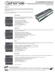
Expansion Modules 123<br />
Remote Devices 123<br />
<strong>Network</strong> - Controller connection 124<br />
USB 124<br />
Connecting the Controller via USB 124<br />
Ethernet 124<br />
DHCP (default) 124<br />
Link local (DHCP error) 124<br />
Static IP (optional) 124<br />
- 10 -
Contents<br />
Multicast ports 124<br />
Default gateway 125<br />
Managed switches and firewalls 125<br />
EDMX considerations 125<br />
<strong>Network</strong> window 125<br />
Controller firmware 126<br />
To update a Controller's firmware: 126<br />
<strong>Network</strong> - Controller association 127<br />
Project vs real Controllers 127<br />
Managing project MSCs 127<br />
To add and set the type of a project MSC: 128<br />
To delete a project MSC: 128<br />
Managing project AVCs 128<br />
Associating project Controllers with real Controllers 128<br />
To associate a Controller: 128<br />
To identify a Controller (beacon): 128<br />
Time Server 128<br />
To change the Time Server: 129<br />
Web interface tools 129<br />
To view a Controller's web interface: 129<br />
To create files for uploading via the web interface: 129<br />
File transfer 129<br />
To transfer files to and from a Controller's Compact Flash card: 129<br />
Mac OS X users: 129<br />
Controller status 130<br />
Disabling Output Live 130<br />
<strong>Network</strong> - Controller configuration 131<br />
<strong>Network</strong> 131<br />
Logging 131<br />
Watchdog 132<br />
Remote Logging via Syslog 132<br />
NTP Server 132<br />
Admin Password 132<br />
To change the Controller configuration settings: 132<br />
Date and Time 132<br />
To change manually the Time Server's date and time: 133<br />
To synchronize the Time Server's date and time to Designer: 133<br />
Compact Flash 133<br />
Storing configuration settings on the Compact Flash card (optional) 133<br />
<strong>Network</strong> - Controller properties 135<br />
Identification 135<br />
Screen (AVC only) 135<br />
DMX Refresh Rate (MSC 1 & 2 only) 136<br />
Digital Inputs (MSC 1 & 2 only) 136<br />
Serial Port(s) 136<br />
MIDI In (MSC 1 & 2 only) 136<br />
Real Time 136<br />
Ethernet 137<br />
<strong>Network</strong> - Controller protocols 138<br />
MSC 1 & 2 138<br />
Output 1 (MSC 1 & 2) 138<br />
Output 2 (MSC 2 only) 139<br />
<strong>ETC</strong>Net2 139<br />
- 11 -
Unison Mosaic Designer User Manual<br />
KiNet power supplies 139<br />
MSC X 140<br />
<strong>Network</strong> 2 (Protocol) 140<br />
<strong>ETC</strong>Net2 140<br />
KiNet power supplies 140<br />
DVI 141<br />
<strong>Network</strong> - Expansion modules 142<br />
MSC 1 & 2: Expansion Modules 142<br />
DMX-IN 142<br />
RS485 142<br />
LTC 143<br />
AUDIO 143<br />
DALI-M 144<br />
DALI-S 144<br />
MSC X: DMX Input 144<br />
DMX-IN 144<br />
<strong>Network</strong> - Remote Devices 145<br />
Connection 145<br />
TCP/IP 145<br />
Multicast 145<br />
Project vs real Remote Devices 146<br />
Managing project Remote Devices 146<br />
To add and set the type of a project Remote Device: 146<br />
To delete a project Remote Device: 146<br />
Remote Device firmware 146<br />
To update a Remote Device's firmware: 146<br />
Associating Remote Devices 146<br />
To associate a project Remote Device with a real device (automatic addresses 1>15): 146<br />
To associate a project Remote Device with a real device (manual addresses 16>100): 147<br />
Remote Input Output (RIO) device properties 147<br />
Serial Port 147<br />
I/O Configuration 147<br />
Button Panel Station (BPS) device properties 147<br />
Properties 147<br />
Button Configuration 148<br />
Report 149<br />
Report toolbar 149<br />
Equipment 149<br />
Group 149<br />
Patch 149<br />
All Timelines 149<br />
Timeline 150<br />
Trigger 150<br />
<strong>Network</strong> 150<br />
Report spreadsheet 150<br />
Exporting a report 150<br />
Web interface - Default pages 151<br />
Home 151<br />
Project Status 152<br />
Timelines 152<br />
Groups 153<br />
Log 153<br />
General log 153<br />
- 12 -
Contents<br />
System log 153<br />
Output 154<br />
View output 154<br />
Park and Unpark 154<br />
Input 155<br />
DMX 155<br />
Digital inputs 155<br />
Control 155<br />
Command line 156<br />
Triggers 156<br />
Dynamic text slots 156<br />
Configuration 156<br />
Remote upload 157<br />
Custom Page 157<br />
Web interface - Command line 158<br />
Selections 158<br />
Setting intensity 158<br />
Setting RGB 158<br />
Clearing fixture settings 159<br />
Clearing all fixtures settings 159<br />
Multiple Commands 159<br />
Interaction with timeline playback 159<br />
Web interface - Custom page(s) 160<br />
Adding files 160<br />
Removing files 160<br />
Defining the default page 160<br />
Defining triggers 160<br />
Injecting variables 161<br />
Testing conditions 161<br />
Issues 162<br />
Frequently asked questions 165<br />
Software 165<br />
Is the free software a cut-down demo version? 165<br />
Does the Designer software support the Apple Macintosh? 165<br />
What are the PC minimum requirements for Designer software? 165<br />
Are project files compatible across versions and platforms? 165<br />
Can I have multiple versions of Designer on my computer? 165<br />
What documentation is available? 165<br />
How many timelines can I program? How many fixtures, etc? 165<br />
How can I tell what DMX levels are being generated? 166<br />
Where's Undo? 166<br />
Backing up? 166<br />
What are the Unison Mosaic Designer file extensions? 166<br />
Can the project file be retrieved from the Controller(s)? 166<br />
How best to archive a project? 166<br />
How do I programme RS232, RS485 or Ethernet triggers? 167<br />
Fixtures 167<br />
What happens if I need a fixture that isn't in the library? 167<br />
I have a fixture with lots of DMX modes, which mode should I use? 167<br />
Hardware 168<br />
What show control interfaces does the MSC 1 & 2 support? 168<br />
Is Unison Mosaic RDM compatible? 168<br />
Will I need more memory on the Controller? 168<br />
- 13 -
Unison Mosaic Designer User Manual<br />
Are there any diagnostic tools? 168<br />
When should I use reset? 168<br />
Should I keep Controllers in the field up-to-date with the latest firmware? 168<br />
What warranty does <strong>ETC</strong> offer? 168<br />
What user serviceable parts are there in a Controller or Expansion Module? 169<br />
Standards compliance? 169<br />
<strong>Network</strong> 169<br />
What are the differences between connecting to a PC via USB and Ethernet? 169<br />
How do the Unison Mosaic products cope with sharing a network with other, non-lighting<br />
169<br />
devices?<br />
What about remote focus units, portable control stations, IR, etc? 169<br />
Is there a way to call up channels for focus? 169<br />
Troubleshooting 170<br />
What are the Controller's LEDs telling me? 170<br />
Status LEDs 170<br />
Error codes 170<br />
Why can't I see the Controller in the Designer network window? 170<br />
USB problems 170<br />
Ethernet problems (network) 171<br />
Ethernet problems (one-to-one) 171<br />
I can see the Controller in the network window but it is shown in grey? 171<br />
I can see the Controller in the network window but it is shown in red? 171<br />
Simulation looks fine but when I upload to the MSC nothing happens? 171<br />
Output Live does nothing? 171<br />
Why do I see a delay between the simulation and the MSC in Output Live? 171<br />
Uploading was working ok but now always fails? 172<br />
When I try to Upload I see a list of issues instead? 172<br />
Is there a way of seeing what the Controller is doing? 172<br />
I get a "Magic number does not match" error when opening a project file? 172<br />
I get loads of warnings about custom fixtures when opening a project file? 172<br />
I have forgotten the Controller's password? 172<br />
I have checked the FAQ and troubleshooting but I'm still stuck? 173<br />
Output viewer 174<br />
Unpatched universe 174<br />
Patched, simulator not running (reset) 174<br />
Patched, simulator running (playing or paused) 174<br />
Output Live 175<br />
Log viewer 176<br />
USB Recovery Tool 177<br />
When to use it 177<br />
To update the bootloader 177<br />
To recover corrupt firmware 177<br />
How to use it 177<br />
Connect the MSC via USB 177<br />
Run the tool 178<br />
MSC X Recovery Tool 179<br />
When to use it 179<br />
To recover corrupt firmware 179<br />
To install a new or larger capacity card 179<br />
How to use it 179<br />
Remove the MSC X's Compact Flash card 179<br />
Plug the Compact Flash card into a CF card reader on a PC 179<br />
- 14 -
Contents<br />
Run the tool 180<br />
Reinsert the Compact Flash card into the MSC X & reboot 181<br />
Software release notes 183<br />
Release Notes 183<br />
Software Licences 183<br />
GPL 183<br />
System limits & capacities 184<br />
Lua scripts 185<br />
Lua script editor 185<br />
Debugging Lua scripts 185<br />
Unison Mosaic language extensions for triggers 186<br />
Accessing the realtime clock (local to this Controller) 186<br />
Accessing the calculated sunrise and sunset times (local to this Controller) 186<br />
Accessing the current state of the digital inputs on this Controller 186<br />
Accessing the values of DMX inputs on expansion modules (local to this Controller) 186<br />
Checking the status of timelines (local to this Controller) 187<br />
Injecting a trigger 187<br />
Timeline control 187<br />
Fixture control (local to this Controller) 187<br />
Accessing the values of DMX outputs (local to this Controller) 188<br />
Park and Unpark DMX channels (local to this Controller) 188<br />
Accessing the current state of the digital inputs on a RIO 188<br />
Accessing trigger variables 188<br />
Writing messages to the Controller's status log 188<br />
Storing data on the Compact Flash card 189<br />
Trigger Programming Guide 190<br />
Introduction 190<br />
The Basics 190<br />
Comments 191<br />
Variables 191<br />
Arithmetic 191<br />
Flow of Control 192<br />
Tables 193<br />
Functions 193<br />
Practical Examples 194<br />
Cycling through different timelines 194<br />
Make a timeline loop N times 196<br />
Track motion sensor activity over a period of time 197<br />
Inverting a DMX input before it is used with a Set Intensity action 198<br />
Interpreting data from a wind direction sensor 198<br />
Using a table of times for high and low tide 200<br />
Implementing an interactive game for a Science Museum 202<br />
More information 202<br />
Custom Preset Programming Guide 203<br />
Basics 203<br />
Listing 1 203<br />
Listing 2 203<br />
A real example 203<br />
Listing 3 203<br />
Animation 204<br />
Listing 4 204<br />
Listing 5 205<br />
Listing 6 205<br />
- 15 -
Unison Mosaic Designer User Manual<br />
More colours than just red 206<br />
Listing 7 206<br />
Working with colours 207<br />
Listing 8 207<br />
Listing 9 208<br />
Listing 10 208<br />
A simple gradient 209<br />
Listing 11 209<br />
Listing 12 209<br />
Working with gradients 210<br />
Listing 13 210<br />
Listing 14 210<br />
Listing 15 210<br />
Working with properties 211<br />
Boolean properties 212<br />
Integer properties 212<br />
Float properties 212<br />
Colour properties 213<br />
Gradient properties 213<br />
Listing 16 213<br />
Listing 17 213<br />
Colour library summary 214<br />
Properties 215<br />
Gradient library summary 215<br />
Functions 215<br />
Built-in functions 215<br />
Import file formats 217<br />
Import fixture plan file format (*.csv) 217<br />
Fixture type syntax 217<br />
Fixture position syntax 217<br />
Example 217<br />
Import pixel matrix file format (*.csv) 217<br />
Fixture position syntax 218<br />
Example 218<br />
Glossary 219<br />
- 16 -
Welcome<br />
Introduction<br />
Welcome<br />
Welcome and thank you for using version v1.6 of the Unison Mosaic Designer software. This release offers some<br />
significant improvements and additional functionality over earlier versions, see what's new for details.<br />
WARNING: Projects saved with v1.6 can not be opened with earlier versions so please make sure to back up<br />
your programming prior to installation.<br />
Platforms<br />
Unison Mosaic Designer is designed to run on a Microsoft Windows Vista or XP (Home or Professional) or Apple<br />
Macintosh OS-X (10.4.x or later - PowerPC and Intel) personal computer. As the application is of a highly graphical<br />
nature a large monitor is recommended (1024x768 minimum) and the extensive use of OpenGL graphics routines<br />
will benefit from a high performance graphics card. USB or Ethernet support will be required to connect to<br />
the Unison Mosaic hardware.<br />
Apple QuickTime<br />
Apple QuickTime (6.5 or later) must be installed to run Designer and QuickTime 7 is supplied on the Unison<br />
Mosaic Designer installation CD. QuickTime is also available for download at Apple - QuickTime Player.<br />
Help Overview<br />
The Help is split into four major sections: Quick Start, Reference, Troubleshooting, and Appendices.<br />
Those of you experimenting with the software for the first time should work through the Quick Start guide to familiarise<br />
yourself with the basics of the software. The Reference section then gives detailed descriptions of every<br />
aspect of the software as well as the configuration of the Unison Mosaic Controllers and their accessories. The<br />
Troubleshooting section provides help to resolve any problems while the Appendices provide additional useful<br />
resources.<br />
If you have a Controller that you wish to connect to and program now then please read the <strong>Network</strong> section for<br />
instructions although this is not required when working through the Quick Start guide.<br />
Help Help<br />
This is the PDF version of the on-line Help and it is available in various formats for printing. The on-line version,<br />
which has the advantage of being fully searchable and includes animated tutorials, can be opened from within<br />
Designer using Help > Contents on the main toolbar.<br />
Support<br />
As with all successful control products, support is crucial and the team at <strong>ETC</strong> will do everything possible to<br />
ensure that your project is a success. Please do not hesitate to contact us with your questions, bug reports and<br />
suggestions at:<br />
T: (800) 775-4328<br />
E: service@etcconnect.com<br />
- 17 -
Unison Mosaic Designer User Manual<br />
Please also visit our website to keep up to date with the latest product news and software releases: www.etcconnect.com.<br />
- 18 -
What's new in v1.6<br />
Setup<br />
Patch<br />
● Generic AV fixtures (PAL & NTSC, 4:3 & 16:9)<br />
● EDMX (Art-Net II, KiNet etc) output from MSC 1 & 2<br />
● Clone universe function<br />
Media<br />
● AVC tab for AV clip management<br />
● Custom tab for custom preset management<br />
Program<br />
● AVC timeline rows & presets<br />
● Perlin Noise preset<br />
What's new in v1.6<br />
● New shapes in 2D Rainbow, 2D Colour On Colour and 2D Gradient (Bilinear, Noise and Perlin Noise)<br />
● Repeat types in 2D Rainbow, 2D Colour On Colour and 2D Gradient (Sawtooth, Triangle)<br />
● Dynamic Text preset<br />
● Custom presets<br />
Triggers<br />
● Toggle Audio action<br />
● Set Text Slot action (Dynamic Text)<br />
● BPS triggers, conditions and actions<br />
Controllers and Remote Devices<br />
● AVC support<br />
● BPS support<br />
- 19 -
Unison Mosaic Designer User Manual<br />
User Interface<br />
The software has been designed to present a consistent graphical user interface and so it is worth familiarising<br />
yourself with the layout of a typical window before proceeding further:<br />
Main toolbar<br />
The main toolbar contains the File menu to create New projects as well as Open and Save existing projects. The<br />
View menu accesses various optional,typically diagnostic, windows and the Zoom menu allows you quickly to<br />
manipulate the plan or timeline scale and position. The Options menu allows you to configure various applicationwide<br />
options and the Help menu gains access to this help, software build details and the means to check for any<br />
software upgrades.<br />
Mode tabs<br />
The application is divided into ten modes which can be selected by clicking on the appropriate tab. See the Quick<br />
Start overview for a brief description of each mode and then the Reference section for more details.<br />
Mode toolbar<br />
The left hand end of this toolbar always carries the New, Open and Save project buttons. The remainder is populated<br />
with tools as appropriate to the selected mode.<br />
Browser<br />
The browser is common to most modes and provides the primary interface for selecting, expanding and grouping<br />
fixtures in the project. The rows of the browser provide the seeds for Designer's timeline programming interface.<br />
- 20 -
User Interface<br />
Some modes (Simulate, <strong>Network</strong> & Reports) have no browser since fixture selection is not relevant. Scroll bars<br />
will appear as required and the browser can be made wider by dragging the right hand border.<br />
Browser toolbar<br />
The Browser toolbar provides controls for expanding and collapsing groups and compound fixtures as well as for<br />
creating groups and Pixel Matrices.<br />
Plan<br />
A graphical representation of the installation that provides an interface for selecting fixtures and simulating the<br />
results of your programming. This plan simulation is one of Designer's most powerful features as it allows you to<br />
program and visually test your programming when off site. Indeed, this feature can be useful in presenting your<br />
ideas when bidding for a contract.<br />
Configuration area<br />
Depending on the mode and items selected, context-sensitive configuration or control pane(s) will appear here for<br />
fast and convenient editing.<br />
Status bar<br />
Context-sensitive status and progress is displayed in this area.<br />
- 21 -
Unison Mosaic Designer User Manual<br />
Keyboard shortcuts<br />
For ease and speed of use various keyboard keys map to application commands, particularly with regards window<br />
navigation:<br />
● Function keys<br />
Press a function key (F1 thru F10) to change the application’s mode, akin to selecting a<br />
mode tab on the left hand side.<br />
● Ctrl + F8 Press to open or close the Tear-off Simulator.<br />
● Delete / Backspace<br />
● Esc<br />
● Cursor keys<br />
Press Delete or Backspace to delete the selected fixtures or groups of fixtures, a confirm<br />
dialog will appear if this will cause fixtures to be totally removed from the project<br />
with subsequent loss of programming. Press Delete or Backspace to delete the<br />
selected presets from a timeline.<br />
Press Esc to clear the fixture selection. Press Esc to abort a fixture move or timeline<br />
drag operation (preset move/resize).<br />
Use the cursor keys to nudge a fixture selection (Setup) or scroll a matrix or timeline<br />
(Media, Program).<br />
● Shift + cursor key Use to super-nudge a fixture selection (Setup).<br />
● Page Up/Down Use Page Up and Page Down to zoom in and out of a plan, matrix or timeline.<br />
● Tab<br />
● Shift + tab<br />
Use to select the next fixture (with a single fixture selected in Setup, DALI & Mover) or<br />
next editable cell (on a properties tab for example).<br />
Use to select the previous fixture (with a single fixture selected in Setup, DALI &<br />
Mover).<br />
● Ctrl + tab Use to select the next timeline for editing (Program).<br />
● Shift + Ctrl + tab Use to select the previous timeline for editing (Program).<br />
● Ctrl + F Use to fit the plan or timeline to the screen.<br />
● Ctrl + T Use to display the plan at actual size (1:1 pixel mapping).<br />
● Ctrl + click<br />
Hold Ctrl while clicking to select multiple fixtures (Setup, DALI & Mover) or presets (Program).<br />
● Shift + click Hold Shift while clicking to select ranges of fixtures (Setup, DALI & Mover).<br />
● Ctrl + drag<br />
● Shift + drag<br />
Hold Ctrl while dragging a preset on a timeline to snap to the start/end of other placed<br />
presets (Program) or while dragging a fixture selection to copy the selection using the<br />
same relative layout (Setup).<br />
Hold Shift while dragging a preset on a timeline for finer resolution (Program) or while<br />
dragging a fixture selection to invert the Snap To Grid behaviour (Setup).<br />
● Ctrl + A Select all fixtures (Setup, DALI & Mover) or presets (Program).<br />
● Ctrl + N New project.<br />
- 22 -
● Ctrl + O Open project.<br />
● Ctrl + S Save project.<br />
● Ctrl + E<br />
Keyboard shortcuts<br />
Export project (exports the project including media & plan background image for transfer<br />
or backup purposes).<br />
● Ctrl + U Upload to the Controller(s).<br />
● Ctrl + shift + U Save Snapshots.<br />
● Ctrl + Q Quit the Designer application.<br />
● Spacebar Start or pause the simulator.<br />
● F Drops a flag in learn timing mode<br />
Notes for Macintosh users<br />
Unison Mosaic Designer makes a good deal of use of the two button mouse with right-click being used to invoke<br />
context-sensitive dialogs. As the majority of Mac users have only a single button mouse they must hold Ctrl while<br />
clicking to get this functionality. Furthermore Macs have an Apple key that serves as the alternative to the Windows<br />
Ctrl key. Shift and Alt work as described for Windows.<br />
- 23 -
Unison Mosaic Designer User Manual<br />
Overview<br />
The Designer software is the tool provided to configure and program the Unison Mosaic Controllers and Remote<br />
Devices. The Controllers have been designed specifically for the architectural and installation markets and, as<br />
opposed to DMX frame store solutions, offer genuine lighting,audiovisual and show control functionality.<br />
Lighting & video is programmed on timelines, with a particular timeline having control data for one, some or all the<br />
lighting fixtures being controlled. Multiple timelines are supported and so a single unit can control multiple distinct<br />
zones, or more complex presentations can be programmed with external triggers coming from multiple systems.<br />
The software offers powerful functionality with a simple and intuitive graphical user interface. Most operations<br />
can be performed with mouse clicks (typically left-click for selection and right-click for context sensitive options<br />
& commands) and drag-and-drop. Creating a project is broken down into ten sections, use the mode tabs down<br />
the left hand side of the application or the function keys (in brackets) to toggle between them:<br />
Setup (F1)<br />
In Setup you add your fixtures to the plan, arrange them in groups or customize their behaviour. Use the Properties<br />
pane to import a bitmap for the plan, set the plan’s size and grid spacing and specify the geographic location<br />
of the installation. See Setup reference.<br />
Patch (F2)<br />
In Patch the fixtures are assigned to the connected Controllers (see <strong>Network</strong>) and given DMX universes and<br />
addresses. This step can be skipped during design and only completed during installation. See Patch reference.<br />
DALI (F3)<br />
In DALI you patch and define DALI groups & scenes for any DALI ballasts in the project. Unlike DMX fixtures,<br />
these definitions are stored in the DALI ballasts themselves and so the configuration must be uploaded separately<br />
from here. See DALI reference.<br />
Mover (F4)<br />
In Mover you program presets for any automated lights with position or beam manipulation controls. These presets<br />
can then be placed onto timelines along with other programming. See Mover reference.<br />
Media (F5)<br />
Media allows you to create virtual video screens and map fixtures to pixels of the screen. Here you also import<br />
and manage the media files (either static images or video) which can then be played back on these screens and<br />
any audio visual fixtures in the project. See Media reference.<br />
Program (F6)<br />
Program is where you create and edit the timelines that make up your presentation. Each fixture or group of fixtures<br />
is a row of the timeline and you can drag-and-drop from an extensive range of built-in intensity and colour<br />
effects, as well as placing mover presets and media clips. See Program reference.<br />
- 24 -
Trigger (F7)<br />
Overview<br />
In Triggers you connect your programming with the real world. At its most basic you can define which timeline to<br />
begin on startup but for more complex environments with external triggers you can define a detailed script, even<br />
incorporating conditions if necessary. See Trigger reference.<br />
Simulate (F8)<br />
Simulate allows you to view a representation of your project in plan format. You can play individual timelines to<br />
check your programming then run the whole project including triggers. A set of buttons allow you to simulate external<br />
triggers in order to test your programming properly. See Simulate reference.<br />
The Simulator can also be opened in its own window so that it is permanently available, typically on a second<br />
monitor. Tear off (click and then drag to the right) the Simulate mode tab or press Ctrl (Apple) + F8 to open this<br />
window.<br />
<strong>Network</strong> (F9)<br />
This is where you manage your Unison Mosaic hardware, assigning connected Controllers to the Controllers in<br />
your project, configuring their input/output interfaces and any attached Expansion Modules or connected Remote<br />
Devices. See <strong>Network</strong> reference.<br />
Report (F10)<br />
Here you can view and organise spreadsheet-style reports listing the elements within the project for example fixture<br />
schedule, patch, triggers. This is useful in providing documentation about the installation for future reference<br />
and to aid maintenance. Reports can be exported as *.tsv files (Tab Separated Values) for importing into an Excel<br />
spreadsheet for formatting and printing. See Report reference.<br />
- 25 -
Unison Mosaic Designer User Manual<br />
Quick Start<br />
Creating a project<br />
Having installed QuickTime and Designer, launch the application and select New Project from the Launch Project<br />
dialog, choose a location for the file to be stored and give it a memorable name. A blank project will then be<br />
created and the application will enter the Setup window ready for you to configure your plan, place your fixtures<br />
and start programming.<br />
To create a simple Unison Mosaic Designer project we will consider these four stages:<br />
1. Setting up your plan, fixtures and patch<br />
2. Creating Media and Mover presets ready to use when programming<br />
3. Programming your timelines<br />
4. Creating the triggers that will operate your show<br />
Getting started: Adding Dimmers, LEDs and Moving Lights to the plan and<br />
patching them<br />
1. From the Fixture Library pane, select Dimmer from the Generic manufacturer and drag to the plan.<br />
2. Right click (Ctrl Click for Mac users) on the inserted fixture, click on Duplicate Fixture, edit Width to 6 and<br />
click Ok.<br />
3. Return to the Generic manufacturer, select LED-RGB and drag to the plan. Right-click, select Duplicate<br />
and choose a height and width of 8 to create an 8x8 array of these fixtures.<br />
4. From the library, use the drop down menu to select Robe, ColorSpot 1200, drag to plan and duplicate fixture<br />
again, this time 6 in a circle.<br />
5. Notice the fixture browser on the left has populated each fixture in groups based on fixture type. The three<br />
tree buttons above the browser allow you to expand and collapse the items. Collapse all for now.<br />
6. Next we will generate Pixel Matrices for applying 2-dimensional colour effects and media presets.<br />
7. Drag a box around the LED array to select all fixtures. Click on the Matrix button above the browser to<br />
create a new matrix. Rename it "LED Matrix".<br />
8. Repeat with the moving lights to create another matrix and name it all "ML Matrix".<br />
9. Click on the Patch tab on the far left hand side of the screen to change to the Patch window.<br />
10. Drag each group on to the blank universe to patch all fixtures. (This step is not essential to programme and<br />
simulate).<br />
Creating Media & Mover presets<br />
1. Click on the Mover tab at the left to change to the Mover view.<br />
2. In the configuration area select the Mover tab and press Create New. Select the moving lights by dragging<br />
a box around them on the plan, or click on their group in the browser.<br />
3. In the parameter pane click on the Position, Colour and Beam tabs and choose values for these attributes.<br />
4. To create a further presets, simply leave your current programming and click Create New.<br />
5. Click on the Media tab at the left to change to the Media view.<br />
6. Select your LED matrix. You can move the pixels in relation to each other and resize the array window if<br />
desired.<br />
7. To import media click on Create New in the Media configuration pane. The Designer installer provides sample<br />
media which is located in Program Files at \<strong>ETC</strong>\Mosaic\Designer\resources\media_samples.<br />
- 26 -
Programming Timelines<br />
Quick Start<br />
1. Click on the Program tab at the left to change to the Program view.<br />
2. Note the fixture browser now has timeline rows associated with each fixture, group, or matrix, and two<br />
Mover rows have been created. Note also the preset directories on the lower right-hand side of the window:<br />
the Group directory includes built-in presets that can be applied to Group and Fixture rows, the Matrix<br />
directory includes built-in presets that can be applied to Pixel Matrices, the Media directory has been populated<br />
with any media you imported, and the Mover directory has been populated with the Mover presets<br />
you created.<br />
3. Click on the Group directory tab. Select and drag the Fixed Colour preset to your All LED group, and drop<br />
at the start of the row. You can adjust the position and length of the effect on the row by dragging it on the<br />
timeline and selecting the handles at the end of the preset. The preset properties (in this case just colour)<br />
can be edited in the Properties pane. Fade times and characteristics can be edited in the Transitions pane.<br />
4. Choose other presets from the Group directory, such as Rainbow and Sparkle, experiment with dropping<br />
them on your groups, or open up the group and apply to individual fixtures, and edit parameters.<br />
5. To view your timeline, drag the Simulate tab at the left onto the Program view to open the Simulate window<br />
on top of the Program window. Click on the play button to run the timeline.<br />
6. Click on the Matrix directory. Drag these presets onto your LED Matrix row. Experiment with parameters<br />
and simulation.<br />
7. Click on the Media directory. Drag your media clip onto your one of your Matrix rows. Experiment with<br />
parameters and simulation. (To experiment with the matrix size, e.g. to modify the resolution or the viewable<br />
area of the media, return to the Media window and adjust the dimensions of the matrix, the position of<br />
the pixels, etc.).<br />
8. Click on the Mover directory. Drag your Mover presets to one of the Mover rows. Click on the Group directory<br />
and drag intensity to the fixture / group row to apply intensity. For CMY fixtures, apply colour effects.<br />
9. Use the intensity preset to programme the Dimmer fixtures.<br />
10. Create additional timelines by clicking on New Timeline. Name as appropriate and programme.<br />
Creating Triggers<br />
1. Click on the Trigger tab at the left to change to the Trigger view.<br />
2. Note that Trigger, Condition and Action directories are to the left of the worksheet area, to the right are<br />
properties panes for editing parameters, selecting components, etc.<br />
3. To create a Startup trigger, click Start up in the Trigger directory and drag into the main worksheet area.<br />
Give it a descriptive comment. Drag Start Timeline from the Actions directory to the new Startup trigger<br />
row on the worksheet, and under Action Data in the Actions pane select a timeline from the dropdown<br />
menu.<br />
4. Repeat, experimenting with different Triggers and different Actions. Note Change button for Real Time<br />
parameters, and Edit for the MIDI message builder. Question marks (???) on the worksheet will indicate<br />
where parameters or values need to be set<br />
5. To create a conditional trigger, create a Digital Input trigger. Set it to input 1, drag a Start Timeline Action<br />
and select a timeline to play. Copy and paste the trigger (right click / Mac Ctrl+click). On the earlier trigger<br />
drag an Astronomical condition which will default to After Sunset. Set Action to play a different timeline.<br />
This achieves a condition option and a catch-all option if the condition does not apply.<br />
6. Return to Simulate. Select Project above the control area. All the triggers you have created appear below.<br />
Clicking Play will activate the Startup trigger. Run your project, utilizing the triggers to mimic contact closures,<br />
real time triggers, serial messages, etc.<br />
- 27 -
Unison Mosaic Designer User Manual<br />
Setup - Project properties<br />
With no fixtures selected, the Project Properties pane is displayed:<br />
Project Identification<br />
The project filename (*.mdp) and path is displayed for reference.<br />
Underneath are two fields for optionally entering a project title and the project's author, these fields are displayed<br />
on the Controller's web interface home page and are useful for reference once the installation completed.<br />
If the title field is left blank the web interface will instead display the project's filename which may be useful for<br />
tracking iterative versions.<br />
Plan<br />
Size<br />
The plan size can be set via the Width and Height fields (in pixels) and a solid background colour selected by<br />
clicking the Background browse button. The maximum plan size is 8192x8192 pixels.<br />
Grid<br />
The spacing of the working grid can be specified (again in pixels) and there are options to show this grid and<br />
whether fixtures should snap to it. This grid is useful in accurately and easily placing fixtures.<br />
- 28 -
Background image<br />
Setup - Project properties<br />
To use a background image click on the button next to the Image entry to browse for an image, either a Windows<br />
(*.bmp), Portable <strong>Network</strong> Graphics (*.png) or JPEG (*.jpg) image can be imported and it is envisaged that this<br />
image be a graphical representation of the installation, perhaps derived from architectural CAD drawings.<br />
Use the Windows Alt + Print Screen command to take a screen shot of your CAD application and then use a bitmap<br />
editor to crop and resize the image to suit (see scale). Again, the maximum plan size is 8192x8192 so make<br />
sure the bitmap is smaller or equal to these values. The plan size will automatically adjust to be that of this image.<br />
When planning a fixture layout, give consideration to fixture selection and visualization. Particularly with large layouts,<br />
an abstracted arrangement of fixtures may be easier to view and work with than a pixel perfect, scale accurate<br />
representation.<br />
Scale<br />
The Unison Mosaic Designer fixture library uses a scale of 1cm:1pixel (0.394":1pixel) for the fixture icons so, for<br />
best results, the plan bitmap should be sized to this scale. If your installation too large to be accommodated at<br />
this scale (i.e. bigger than 81.92m in either axis) then change the scale and use the Fixture Position settings to<br />
adjust the scale of your fixture icons accordingly.<br />
Colour scheme<br />
It may be desirable to change the colour of programmed and selected fixtures to aid clarity depending on the plan<br />
background colour or image, use the browse buttons to select appropriate colours. A darker background makes<br />
visualization clearer.<br />
Location<br />
City or Latitude/Longitude<br />
At the bottom are the fields to set the location of the installation to ensure correct operation of the Controller's<br />
internal astronomical clocks. A city picker is provided to facilitate the coordinate entry but values can be entered<br />
directly into the Latitude and Longitude boxes - a web map service such as www.multimap.com is a useful<br />
resource for collecting this information.<br />
Time zone<br />
The local time zone can be entered as an offset to GMT, for example New York would be -05:00 being 5 hours<br />
behind GMT. If the city picker is used to select the location then the time zone will automatically be set.<br />
NOTE: If such an offset is set then the Controller's date and time must be set to GMT not local time or this offset<br />
will be doubled.<br />
- 29 -
Unison Mosaic Designer User Manual<br />
Daylight Saving Time<br />
Check the Daylight Saving Time box to enable automatic DST adjustment. The rules for Daylight Saving differ by<br />
region but, if the city picker is used to select the location, the correct settings for that region should appear in the<br />
Starts and Ends fields although it is recommended that you check that they are indeed valid. Alternatively, specific<br />
dates can be entered (the year is ignored).<br />
- 30 -
Setup - Adding & organising fixtures<br />
Setup - Adding & organising fixtures<br />
Once you have the plan setup as desired you can start populating it with the fixtures as required for the installation:<br />
Fixture Library<br />
Unison Mosaic Designer incorporates a comprehensive fixture library grouped by manufacturer. A generic manufacturer<br />
is provided for standard fixtures such as dimmers, basic RGB LEDs and non-dim items that need to be<br />
switched such as fans or smoke machines.<br />
A custom manufacturer is created when you make your own fixtures, either by right-clicking on a fixture within the<br />
library picker (not once placed on the plan) and selecting Customise Fixture to use this fixture as a starting point,<br />
or by pressing the Fixture Editor button at the top to create a fixture from scratch. Both operations will open the<br />
Fixture Editor.<br />
Note however that common settings such as colour & gobo slots, size, shape and dimmer curve etc. can all be<br />
set on an individual fixture basis using the Fixture Configuration pane once the fixture has been deployed and<br />
selected, so creating a custom fixture library entry,a relatively complex process, may not be necessary.<br />
Fixture icons & scale<br />
The following icons are used to differentiate between fixture classes:<br />
Moving light - wash DALI ballast (see DALI)<br />
- 31 -
Unison Mosaic Designer User Manual<br />
Moving light - spot Conventional fixture<br />
Moving light - mirror<br />
Accessory (eg. scroller) Media server<br />
Non-dim (switched control channel) or controller<br />
Discrete LED fixture (to scale) Compound LED fixture (to scale)<br />
4:3 PAL/NTSC AV device 16:9 PAL/NTSC AV device<br />
The LED and compound LED fixture icons are drawn to scale (1cm:1pixel) so that, coupled with a correctly<br />
scaled background image, the resulting plan and simulation is as realistic as possible. The other icons are drawn<br />
to a standard size that, in most cases, will produce a realistic result. All placed fixture icons can however have<br />
their size (scale) and even shape modified using the Fixture Configuration pane.<br />
When using the Simulator these icons instead render the fixture's output, even displaying the selected gobo and<br />
iris settings for moving lights.<br />
Populating the plan<br />
Simply chose a manufacturer, select the required fixture by clicking on it and then drag it onto its position on the<br />
plan, it will automatically be added to the Browser and grouped with all other fixtures of that type. Once placed,<br />
left click to select it, a red highlight will indicate the current selection, see selecting fixtures. Right click to delete,<br />
group or duplicate fixtures.<br />
To add a fixture:<br />
1. Use the drop down menu at the top of the library browser to select the manufacturer<br />
2. Locate the required fixture<br />
3. Click and drag the fixture onto the plan and release the mouse button to drop it (it will automatically be<br />
added to the Browser)<br />
To duplicate a fixture (create an array):<br />
1. Right-click on the fixture (on the plan not the Browser) to be duplicated<br />
2. Select "Duplicate"<br />
3. Select either "Rectangle" or "Circle"<br />
4. Set the duplication parameters, see below<br />
5. Press Ok<br />
For rectangular arrays, positive width and height values will place the copies to the right and below respectively,<br />
negative to the left and above. Select either Rows or Columns to set the direction of the fixture numbering.<br />
- 32 -
Setup - Adding & organising fixtures<br />
For circular arrays, select the radius, direction and count (number of fixtures) - complete circles are created in this<br />
way so, if arcs required, just delete those fixtures that are unwanted.<br />
To copy a fixture or fixture selection:<br />
1. Select the fixture(s)<br />
2. Press and hold Ctrl (Apple)<br />
3. Drag the copy to a new location on the plan and release the mouse button to drop (with multiple fixtures,<br />
their relative layout is preserved)<br />
Note that pressing Ctrl after starting to drag will cause the selection to jump back to its original position and<br />
create a copy of the selection under the pointer.<br />
To delete a fixture or fixture selection:<br />
1. Select the fixture(s)<br />
2. Press Delete or right-click > Delete<br />
3. Press Delete to confirm (or Cancel to abort)<br />
Note that the fixture(s) will be completely removed from the project and all programming discarded.<br />
DALI fixtures<br />
DALI fixtures/ballasts are dragged onto the plan in the same way as all other fixtures but they do not populate the<br />
Browser and no groups are automatically made since DALI fixtures are programmed and controlled via dedicated<br />
DALI Interfaces, see DALI.<br />
Audio visual (AV) fixtures<br />
Select "Generic Video" from the drop down of manufacturers. Choose the appropriate type of device (PAL or<br />
NTSC,16:9 or 4:3) and drag it onto the plan, just as you would for a lighting fixture.<br />
However, unlike other fixtures, this will automatically add a project AVC to control that device, see Controller<br />
Association. Similarly duplicating or deleting these AV fixtures will automatically add or delete AVCs as required.<br />
It is important to appreciate that AV fixtures are treated differently to lighting fixtures in that they are directly coupled<br />
to an AVC (which takes the same name) and thus require no patching. The AV fixture and its AVC should be<br />
thought of as a single, integrated entity. See Working with the AVC for information about programming AV fixtures<br />
and AVC playback.<br />
Import fixture plan<br />
You can use File > Import Fixture Plan to import a fixture layout from a CAD application via a CSV file, see import<br />
fixture plan file format.<br />
- 33 -
Unison Mosaic Designer User Manual<br />
Fixture Identification<br />
With a fixture selected the top two fields detail the fixture's manufacturer (manufacturer id) and model (model id),<br />
they are for reference only and can not be edited.<br />
Name & number<br />
Here you can enter a new name for the fixture, useful to help make the browser easier to navigate, and the means<br />
to change the fixture's unique user number.<br />
Every fixture added to the project is assigned a user number which is used as a shorthand method of selecting it,<br />
using the web interface's command line for example. Use the up and down arrows to change the number but note<br />
that only available numbers are shown so you may need to change the number of another fixture first to make that<br />
number available. Note that the user number does not affect the order of the fixtures in the Browser and thus the<br />
order used for transitions.<br />
Locked<br />
Select "Yes" to prevent the fixture(s) from being moved or included in drag selections. Evidently, once locked,<br />
drag selection is prohibited to select multiple fixtures to unlock so you must use the Browser instead.<br />
Comments<br />
Below this are two fields for entering any comments about the fixture, these comments will appear in the fixture<br />
report, useful for annotating the project's documentation.<br />
Fixture Position<br />
Use these fields to set numerically the fixture's position and orientation on the plan and to change the size and<br />
shape of the fixture's icon, useful for tweaking their scale to that of the plan background if the default scale not<br />
used (1cm:1pixel).<br />
It is desirable to position the fixtures on the plan as accurately as possible to improve both the accuracy of the programming<br />
(in particular pixel matrices created automatically from the plan layout) and the general neatness of the<br />
project and simulation.<br />
Grid<br />
Use the plan properties to set the spacing of the plan's grid, whether it is displayed and whether fixtures should<br />
snap to it. Holding Shift while dragging a fixture selection will invert the snap to grid behaviour.<br />
Nudge<br />
Use the cursor keys to nudge a fixture selection up, down, left or right by the amount set as the grid spacing. Alternatively,<br />
use the up and down arrows by each of the fixture's position fields. Holding Shift while using the cursor<br />
keys performs a super-nudge of 10x the grid spacing.<br />
- 34 -
Alignment<br />
Setup - Adding & organising fixtures<br />
Fixtures can be aligned to one another by making the selection and entering the value to be shared into the appropriate<br />
position field.<br />
Fixture Configuration<br />
This pane allows you to configure the selected fixture(s):<br />
Intensity<br />
The fixture's dimmer curve and maximum intensity can be set, use the Dimmer Curve pull-down to determine the<br />
type of cross fade the intensity channel will perform and set a Maximum Intensity level, useful for balancing light<br />
output.<br />
DALI<br />
DALI ballasts can be configured as allowed for by the DALI standard; Min Level (0>254), Max Level (0>254),<br />
Power On Level (1>254) and Bus Failure level (No change, 0>254). The standard specifies a level range of 0>254<br />
with 255 being used as a special case meaning "no change", a mask if you like. Unlike DMX fixtures, these settings<br />
are stored in the ballasts themselves and so must be uploaded separately, see DALI.<br />
Moving lights<br />
Moving lights can be customised for the project as one would on any sophisticated moving light console. Use<br />
Invert Pan, Invert Tilt and Swap Pan & Tilt to normalise the way they respond to the position controls and customise<br />
the fixture’s gobo & colour wheels.<br />
Gel colour<br />
For those working with gelled lights it is possible to simulate the gel’s colour so that the fixtures are rendered correctly,<br />
press the Change Gel button and select the required colour via the colour picker.<br />
Reset to Defaults<br />
Use this to force the fixture to be redefined from its library definition, losing local changes and thus restoring it to<br />
its defaults. This is useful for updating fixtures on the plan with any library definition edits, forcing a redraw. Local<br />
changes to a fixture's geometry (shape, size) will be overwritten.<br />
Highlight Patched Status<br />
On the toolbar, use the Show patched on pull-down to select a Controller and then press Highlight to highlight the<br />
fixtures that are patched to that Controller. Select None instead of a Controller to highlight unpatched fixtures.<br />
Press Highlight again to turn it off.<br />
- 35 -
Unison Mosaic Designer User Manual<br />
Selecting fixtures<br />
There are various ways of selecting fixtures which are common to all windows so it is worth covering them now:<br />
Browser<br />
The Browser is the most powerful and flexible method of selecting fixtures. Click on a group heading to select all<br />
fixtures within the group, expand a group by clicking on the plus sign and click on fixtures within to select individual<br />
fixtures and, with compound fixtures, expand them to select the individual pixels within. Fixtures and pixels<br />
are shown in red when selected.<br />
Hold down Shift while clicking to select all contiguous groups/fixtures/pixels between clicks and hold down Ctrl<br />
(Apple on Mac) while clicking to select multiple non-contiguous individual groups/fixtures/pixels. Hold down Ctrl<br />
(Apple) while clicking to deselect a selected group/fixture/pixel.<br />
Pressing Esc or clicking “in space” (anywhere on the Browser that isn’t a fixture) clears the selection.<br />
The Browser also provides the interface to view and change the ordering of fixtures/pixels within groups. This<br />
order is used by the application to determine cue timing and effects skews, simply drag fixtures about within the<br />
Browser to change this order.<br />
Plan<br />
Only fixtures and pixels can be selected using the plan, to select groups you must use the Browser. Fixtures and<br />
pixels are shown in red when selected.<br />
Shift and Ctrl (Apple) work with clicking as described above to select/deselect and you can also lasso fixtures by<br />
clicking and dragging around them, fixtures must be wholly enclosed to be selected.<br />
Hold down Alt to select individual pixels within compound fixtures. Hold down Alt and Ctrl (Apple) to select/deselect<br />
multiple pixels.<br />
Pressing Esc or clicking “in space” (anywhere on the Plan that isn’t a fixture) clears the selection.<br />
Select next/previous fixture<br />
With a single fixture selected, the Tab key will select the next fixture (next higher fixture number) and Shift + Tab<br />
will select the previous fixture (next lower fixture number).<br />
Select all fixtures<br />
Ctrl + A will select all fixtures.<br />
Groups<br />
Groups are an important concept to grasp as they serve three purposes:<br />
- 36 -
Selecting fixtures<br />
Firstly, as you will see later, it is the rows of the Browser that make up the rows of the Program timeline interface<br />
thus it is convenient to gather fixtures/pixels that are to be programmed together into a group to simplify this procedure.<br />
Secondly, as the order of fixtures/pixels within a group determines how programming and timing is rendered, it is<br />
sometimes useful to make multiple groups of the same fixtures with different ordering.<br />
Finally, Groups can be used to set up intensity control zones in the Triggers window.<br />
To create a group:<br />
1. Select the fixtures you want to group using the Browser, the Plan or both - the order you do this in determines<br />
the order within the group<br />
2. Right-click a member and choose Create Group From Selection or press the New Group button at the top<br />
of the Browser<br />
3. Name the group which has been created in the Browser containing those fixtures<br />
Alternatively:<br />
1. Press New Group with no fixtures selected<br />
2. Name this empty group<br />
3. Drag fixture/pixel selections into the group from within the Browser - the order you do this in determines<br />
the order within the group<br />
- 37 -
Unison Mosaic Designer User Manual<br />
Setup - Fixture editor<br />
While we endeavour to provide a comprehensive library of DMX compatible fixtures, a Fixture Editor is provided<br />
either to customise existing fixtures or create new ones:<br />
Customised or newly created fixtures will appear in the custom manufacturer folder. However, while we build up<br />
our database of fixture data we would actually prefer you to contact us to have your fixture added to the standard,<br />
distributed library. Please email your fixture request(s) to support.<br />
IMPORTANT: When edits are made to the library definition of a fixture already in the project, the plan will not<br />
update until the fixture has been explicitly reset to its library defaults, see fixture configuration.<br />
Electronic Theatre Controls, Inc. subscribes to the Carallon Automated Lighting Data Service.<br />
- 38 -
Preferences<br />
Select Options > Preferences on the main toolbar to open the Preferences dialog:<br />
General<br />
Select the General tab to change the default behaviour of Designer:<br />
Intensity model<br />
Preferences<br />
Choose whether intensity and DALI presets are programmed using Percent (0>100%) or 8-bit (0>255) values.<br />
Colour model<br />
Choose whether colours are specified using RGB (additive) or CMY (subtractive) values, the latter might feel<br />
more natural for moving light console users.<br />
Number of backups<br />
Designer can keep a number old versions of the project file when you save and it is here that you set the number<br />
of old files to keep. Before saving your project (File > Save or Ctrl+S), Designer will rename the project file on<br />
disk by adding the current time and date to the file name, such as "my_project_bak_2007-04-18_15-58-09.mdp".<br />
If you already have the specified number of backups, the oldest backup will be removed from the disk.<br />
Use File > Save As to produce manual backups of the project at each important programming milestone.<br />
Autosave interval<br />
Designer can periodically create an automatic backup of your programming and it is here that you turn this feature<br />
on and set the backup interval in minutes. Designer will maintain a backup file named "my_project_auto.mdp"<br />
which can be opened to retrieve recent programming in the event of a software crash. This file will be deleted if<br />
the Designer project is closed normally.<br />
- 39 -
Unison Mosaic Designer User Manual<br />
Simulate using timecode from MSC<br />
When simulating a timeline that has been set to use a timecode source (see timeline properties) the simulator<br />
will, by default, emulate the timecode. If, however, a Controller is connected and receiving real timecode then the<br />
simulator can instead be made to track this real timecode by checking this box.<br />
Show Launch dialog<br />
Choose whether the Launch dialog is automatically opened at startup (default), uncheck this box to suppress this<br />
dialog.<br />
Close Upload Dialog after successful Upload All<br />
Check this to have the Upload Dialog close automatically after a successful Upload All.<br />
Patch<br />
Select the Patch tab to change the default settings for patching:<br />
Channels per row<br />
The Channels per row entry box lets you determine how many DMX channels per row are displayed which is useful<br />
for organising the display for complex fixtures; set this number to be a multiple of the number of channels a fixture<br />
uses to get a neater, tabulated display.<br />
Timeline<br />
Select the Timelines tab to change the default settings for timelines and presets:<br />
- 40 -
New timeline properties<br />
Specify the default name and length for subsequently created timelines, see timeline properties.<br />
New preset properties<br />
Specify the default properties for subsequently added presets, see preset types and properties.<br />
Background Colour<br />
Preferences<br />
The background colour of the timeline area of the Program window can be chosen here, press the button and<br />
select a colour. This is useful to make certain types of programming stand out better, for example a project using<br />
mainly intensity presets may be clearer with a dark grey background.<br />
Triggers<br />
Select the Triggers tab to change the default settings for triggers:<br />
- 41 -
Unison Mosaic Designer User Manual<br />
Short MIDI data format<br />
Select the default Short MIDI message data format to be either Decimal or Hexadecimal.<br />
- 42 -
Patch<br />
Once you have created your plan and added your fixtures you need to patch them, that is to say connect them to<br />
real fixtures via the appropriate Controller (MSC 1, 2 or X), interface (port), protocol and address. Patching is<br />
optional for programming and simulation but fixtures must be patched eventually for the MSCs to control them,<br />
including using Output Live in the Simulator.<br />
NOTE: The AVC does not require patching.<br />
Before we cover patching in detail let's look at some of the terms used:<br />
Patch terminology<br />
Term: Description:<br />
DMX<br />
EDMX<br />
KiNet<br />
Art-Net II<br />
Pathport<br />
<strong>ETC</strong>Net2<br />
DVI<br />
DALI<br />
Universe<br />
A digital serial control protocol for entertainment lighting. Officially called<br />
DMX512-A, it was developed by the USITT and has become the standard<br />
protocol for entertainment lighting control using the RS485 physical layer.<br />
A shorthand term for DMX-over-Ethernet protocols, see KiNet, Art-Net II,<br />
<strong>ETC</strong>Net2 and Pathport below.<br />
A proprietary Ethernet control protocol developed by Color Kinetics (now<br />
Philips Solid State Lighting) used to control only their Ethernet PSUs.<br />
A DMX-over-Ethernet protocol developed by Artistic Licence and widely<br />
used in the entertainment industry to distribute multiple universes of DMX<br />
data.<br />
A DMX-over-Ethernet protocol developed by Pathway Communications<br />
and widely used in the entertainment industry to distribute multiple universes<br />
of DMX data.<br />
A DMX-over-Ethernet protocol developed by Electronic Theatre Controls<br />
(<strong>ETC</strong>) and widely used in the entertainment industry to distribute multiple<br />
universes of DMX data.<br />
Digital Video Interface, a standard for the delivery of digital video data to<br />
computer monitors. Used by certain LED manufacturers (for example Element<br />
Labs and Martin Professional) to drive their LED controller products.<br />
For more information:<br />
USITT DMX512<br />
Digital Addressable Lighting Interface, a digital serial control protocol for<br />
architectural lighting. Developed by Philips Lighting it has become a standDALI-AGConard: IEC 60929. DALI fixtures are not patched using this window, see trollerDALI-AG<br />
DALI.<br />
A common term given to a single DMX data link or port. A DMX universe<br />
carries 512 channels of control data each with 8 bit resolution. A single<br />
dimmer will use one channel while more complex fixtures will use multiple<br />
channels as required.<br />
Port The KiNet equivalent to a universe.<br />
DMX Address<br />
The term used to determine which of the 512 control channels of a DMX<br />
universe a fixture should look at to take its own control data. This "start<br />
address" must be set on the fixture or dimmer rack itself as well as patching<br />
the control system.<br />
- 43 -<br />
Patch
Unison Mosaic Designer User Manual<br />
Patch window<br />
This window comprises three sections, to the left is the Browser, to the right the Protocol configuration pane, with<br />
the rest of the window being a graphical representation of a protocol's port or universe. The number of address columns<br />
displayed per row can be changed using Options > Preferences > Patch.<br />
If you are using an MSC X or choosing to output EDMX from an MSC 1 or 2 then you must use the Protocols<br />
pane to configure these protocols, see Controller Protocols.<br />
Patch toolbar & protocol tabs<br />
Use the Controller pull-down to select the Controller for patching. Use the Hide Unused Universe button to suppress<br />
unpatched universes and the Highlight button to bring the selected fixture(s) to its highlight values, typically<br />
100%intensity in open white for easy identification.<br />
Use the tabs across the top of the graphical area to select the required protocol and then the universe or power<br />
supply & port pull-downs to select the target for patching which will be graphically displayed.<br />
Patching DMX & EDMX fixtures<br />
Simply select one or more fixtures in the Browser and drag them onto the required start address of the graphical<br />
representation. Right click on a patched fixture to unpatch it or clear the entire universe/port, drag it to move it<br />
(change its address). Fixtures may be patched to multiple addresses and universes/ports. Patched fixtures are<br />
shown in blue in the Browser, unpatched black.<br />
- 44 -
To patch a fixture:<br />
1. Use Controller and Universe to select the desired Controller and universe of this Controller (if the Controller<br />
has multiple universes)<br />
2. Select the fixture in the Browser<br />
3. Drag and drop the fixture onto the desired start address<br />
To patch multiple fixtures:<br />
1. Use Controller and Universe to select the desired universe<br />
2. Select a group of fixtures in the Browser (see selecting fixtures)<br />
3. Drag and drop the group of fixtures onto the desired start address of the first fixture in the selection<br />
To change a fixture's address:<br />
1. Use Controller and Universe to select the universe on which the fixture is patched<br />
2. Select the fixture(s) on the universe layout and simply drag them to a new address - to move them to<br />
another universe you must unpatch (see below) then repatch<br />
Patch<br />
Fixtures may be patched to as many locations and universes as is required although typically a fixture will only be<br />
patched to one unique address. The Designer software will prompt you with a warning dialogue should you<br />
attempt to patch a fixture that is already patched, select Continue or Unpatch Existing as required. This prompt<br />
can be turned off if it proves aggravating.<br />
However, you can not patch more than one fixture to the same address; a DMX channel can only be controlled by<br />
one parameter so fixtures can't overlap at all. If you drag one fixture onto another the incoming fixture will highlight<br />
in red to alert you that this address is already occupied. If you go ahead and drop it there anyway the software will<br />
prompt you whether to continue and unpatch the existing fixture(s) for you,select Ok to proceed or Cancel to<br />
abort. Again, this prompt can be turned off.<br />
Some fixtures, for example the Vari*lite VL5, need to be patched twice since they have two distinct patch points,<br />
one for the intensity control (patched to the dimmer rack) and another for the fixture's automation controls.<br />
To patch a multiple patch point fixture:<br />
or<br />
1. Locate the fixture in the Browser and expand it by pressing the little plus sign to reveal its patch points<br />
2. Use Controller and Universe to select the desired universe for the first patch point<br />
3. Drag and drop the first patch point onto the desired start address<br />
4. Repeat for the other patch point(s)<br />
1. Patch the entire fixture as one<br />
2. Drag the patch points apart to their desired addresses<br />
- 45 -
Unison Mosaic Designer User Manual<br />
To unpatch a fixture or multiple fixtures:<br />
1. Select one or more fixtures using the Browser or the universe layout<br />
2. Right-click and select Unpatch<br />
To clear all patching from a universe:<br />
1. Use Controller and Universe to select the universe to be cleared<br />
2. Right-click anywhere on the universe layout and select Clear Universe<br />
To clone a universe (copy the patch):<br />
1. Use Controller and Universe to select the universe to be cloned<br />
2. Press the Clone Universe button to open the Clone Patch dialog:<br />
3. Select the target Controller, Protocol and Universe using the pull-down<br />
4. Press Ok to clone the patch to this universe or Cancel to abort<br />
To highlight a fixture:<br />
1. Select one or more fixtures using the Browser or the universe layout<br />
2. Press the Highlight button, the fixture(s) will come on to their highlight defaults (typically open white)<br />
3. Press Highlight again to turn off or select other fixtures to highlight<br />
NOTE: The appropriate Controller must be on the network and correctly associated to highlight fixtures.<br />
To hide unused universes:<br />
1. Select the Controller<br />
2. Press the Hide Unused Universes button, only universes with patched fixtures will be displayed<br />
3. Press Hide Unused Universes again to display all or select another Controller<br />
Patching DVI fixtures (MSC X)<br />
To output data using the DVI port you must first create a pixel matrix that matches the LED controller's pixel map.<br />
Once this has been done, use the Pixel Matrix pull-down on the protocol tab to select which matrix will be output<br />
via the DVI port and select an X & Y offset as required.<br />
- 46 -
The MSC X's DVI port is set to a fixed 1024x768@60Hz resolution which is compatible with most LED controllers.<br />
The LED controller (or monitor) MUST be connected when the MSC X boots or resets for the port to<br />
become active.<br />
Used channels<br />
Patch<br />
At the top of the Protocols pane is an indicator of the number of used and available channels for the selected Controller.<br />
When the Controller is an MSC X, and if you have not associated the controller with a physical device, then you<br />
are allowed to patch as many fixtures as you like.<br />
However, when you associate an MSC X with a physical device, you will only be able to associate to devices<br />
which have a capacity equal or greater than the patched fixtures. After associating with a device, you will be<br />
unable to exceed the capacity of that device.<br />
- 47 -
Unison Mosaic Designer User Manual<br />
DALI<br />
This window need only be used if there are DALI ballasts in the project and one or more DALI-M Expansion Modules<br />
are being used.<br />
Overview<br />
The Digital Addressable Lighting Interface (DALI) is a digital serial control protocol for architectural lighting. Developed<br />
by Philips Lighting it has become a standard: IEC 60929. DALI differs from DMX in a number of important<br />
ways:<br />
● Only 64 ballasts per DALI bus (interface)<br />
● Only 16 groups per interface<br />
● Only 16 scenes per interface<br />
● Ballast configuration (including address), groups and scenes is uploaded to and stored in the ballasts themselves<br />
● Topology-free DALI bus operates at very low data rates<br />
● Command-based protocol, ballasts perform fades and maintain levels<br />
● Only certain discrete fade values are permitted<br />
As a result the DALI protocol is not suitable for rendering effects and media, programming is restricted purely to<br />
recalling lighting levels via the Set Level and DALI Scene presets, see DALI presets.<br />
DALI interfaces<br />
Each DALI-M Expansion Module added to the system supports one DALI bus (up to 64 ballasts) and is assigned<br />
to a DALI interface within Designer. Due to the nature of the DALI protocol, these DALI interfaces are insular<br />
affairs with each having its own unique set of ballasts and groups. Each interface must be configured and<br />
uploaded to individually.<br />
When you add a DALI-M Expansion Module you select which DALI interface it should be assigned to. Only one<br />
Module can be assigned to each interface of which there can be up to 4, use the Add Interface button on the DALI<br />
toolbar to add another, use Remove Interface to remove an unwanted one.<br />
DALI addressing & grouping<br />
Each DALI interface is configured separately, use the pull-down on the DALI toolbar to select an interface for configuration:<br />
- 48 -
The top pane of the DALI interface window displays the 64 real ballast address cells, the bottom pane the group<br />
membership matrix. The Module commands are available to manage the ballasts on each DALI interface.<br />
Module commands<br />
DALI<br />
IMPORTANT: Designer must be connected to the Controllers with DALI-M Expansion Modules and the DALI ballasts<br />
must be active to perform these operations.<br />
A DALI ballast internally stores its address, this is a number between 1 and 64. It is also possible that the ballast<br />
has never been addressed so it does not have an address. These commands are used to discover and address<br />
DALI ballasts:<br />
Find addressed ballasts<br />
This queries the ballasts attached to the Module and reports all addressed ballasts found, an icon is added to<br />
each address cell when the corresponding ballast has been found.<br />
Address ballasts<br />
This finds all ballasts without an address and randomly assigns them a free address. It will not change the<br />
address of any already addressed ballasts.<br />
Readdress all ballasts<br />
This will clear the addresses of all ballasts and then assign every ballast a random address.<br />
- 49 -
Unison Mosaic Designer User Manual<br />
Resolve clash<br />
It is possible that two ballasts can have the same short address. If that happens the ballasts clashing are shown<br />
with a red icon. The resolve clash button will move the clashing ballasts to a random address that is unused by<br />
any other ballast.<br />
To manually readdress a DALI ballast:<br />
1. Select the ballast icon in the current address cell<br />
2. Drag it to the target (preferably empty) address cell<br />
The ballast is readdressed to the target cell. If the target cell was occupied then the ballasts should swap<br />
addresses although this has not been found to be terribly reliable.<br />
To highlight a ballast<br />
Select an address cell (containing a ballast icon) and press Highlight to bring this ballast to full level, select<br />
another cell to highlight instead or press Highlight again to turn off.<br />
Patching DALI fixtures<br />
When you add DALI fixtures to your project plan in setup these"abstract" ballasts are assigned to the Unpatched<br />
DALI group in the Browser and must be mapped to real DALI interfaces and ballasts using this window.<br />
Once you have discovered and addressed all the real DALI ballasts for each interface (if more than one) you can<br />
then patch your DALI fixtures to them simply by dragging them from the Unpatched DALI group onto the required<br />
interface and address cell. As each DALI interface is assigned DALI fixtures, the Browser refreshes to reflect<br />
these changes. The Unpatched DALI group will become empty once all the DALI fixtures in the project have been<br />
patched.<br />
It is of course possible to patch your DALI fixtures blind in advance of being connected to the real ballasts. The<br />
patch is stored with the project data and not on the DALI ballasts.<br />
DALI groups<br />
Unlike other groups in Designer, DALI groups are a property of the real DALI interface not an abstract collection<br />
of fixtures, and there can only be 16 DALI groups per interface. The matrix on the lower pane of the window<br />
allows you to add and define groups for each interface:<br />
To add a DALI group:<br />
1. Press the Add button<br />
2. Type a name by double-clicking the name cell<br />
3. Select which ballasts are to be a member by double-clicking the ballast's cell<br />
The DALI group is added to the Browser and group configuration data ready to be uploaded into the ballasts.<br />
- 50 -
To delete a DALI group:<br />
1. Right-click on the group in the Browser<br />
2. Select Delete<br />
3. Press Ok to confirm<br />
The DALI group is removed and the group configuration data updated ready to be uploaded into the ballasts.<br />
DALI scenes<br />
In Designer's implementation, DALI scenes are common across DALI interfaces, use the pull-down on the DALI<br />
toolbar and select Scene Setup for programming:<br />
The Browser and project plan are displayed so that you can select the DALI fixtures and groups. On the right are<br />
the DALI scenes folder and the Intensity controls.<br />
There can be up to 16 DALI scenes which can contain programming for some or all of your DALI fixtures, even if<br />
spanning different DALI interfaces. In general you should include programming for all your DALI fixtures in each<br />
scene since you can determine when creating timelines which fixtures or groups should run the scene by dropping<br />
the DALI scene on the appropriate timeline row, the choice is yours though.<br />
To create a DALI scene:<br />
1. Press the Create New button<br />
2. Name the new scene<br />
- 51 -<br />
DALI
Unison Mosaic Designer User Manual<br />
3. Select the DALI fixtures or groups<br />
4. Set the required level (0>254), the fixtures on the plan will simulate these levels<br />
The DALI scene is added to the folder and scene configuration data is ready to be uploaded into the ballasts.<br />
To delete a DALI scene:<br />
1. Select the scene in the folder<br />
2. Press Delete<br />
3. Press Yes to confirm<br />
The DALI scene is removed and scene configuration data updated ready to be uploaded into the ballasts.<br />
To edit a DALI scene:<br />
1. Select the scene in the folder<br />
2. Select the DALI fixtures or groups<br />
3. Adjust the levels<br />
The DALI scene is edited and scene configuration data updated ready to be uploaded into the ballasts.<br />
To remove a DALI fixture from a scene:<br />
1. Select the scene in the folder<br />
2. Select the fixture to remove<br />
3. Press the Knockout button to the right of the Intensity controls<br />
The DALI scene is edited and scene configuration data updated ready to be uploaded into the ballasts.<br />
Upload configuration<br />
Once you have configured all your DALI interfaces and programmed all your DALI scenes you must upload the<br />
configuration to each DALI interface in turn so that this data can be stored on the DALI ballasts themselves.<br />
Select an interface using the pull-down on the DALI toolbar and press the Upload Configuration button, a progress<br />
bar will track this rather slow procedure.<br />
- 52 -
Mover<br />
Mover<br />
This window need only be used if there are fixtures in the project that have control parameters other than intensity<br />
and colour mixing. Examples include most automated lights which, above and beyond position (pan & tilt), might<br />
also include gobo and effects wheels:<br />
The Mover window is where one sets these other parameters and it comprises four sections: On the left is the<br />
Browser, in the middle the Plan. Top right is the directory of Mover Presets within the project and below that is the<br />
Fixture Parameters pane and it is here that parameters other than intensity and colour mixing are set.<br />
Parameter kinds<br />
Parameters are grouped by kind:<br />
Intensity Parameters excluding intensity (which is programmed directly on the timeline) such as strobe<br />
Position Pan and tilt<br />
Colour<br />
Parameters excluding colour mixing (which is programmed directly on the timeline) such as<br />
fixed colour wheels and scrollers, colour correction<br />
Beam Image Gobo and effects wheels<br />
Beam Shape Iris, zoom and focus etc<br />
Control Lamp and fixture controls such as dowse, strike, reset and macros<br />
Setting one parameter within a kind sets or “touches” all the rest, the kind heading will turn blue and the Knockout<br />
button will be enabled to indicate that programming for this kind is included in the preset.<br />
- 53 -
Unison Mosaic Designer User Manual<br />
To remove programming press the Knockout button to the right of the kind heading to “untouch” these parameters.<br />
Effects<br />
A realtime effect can also be applied to any parameter by pressing the associated FX button which opens the<br />
effect controls for adjustment, pressing FX again turns off that effect.<br />
Effects work by modulating the programmed base value with a low-frequency oscillator (LFO):<br />
● Effect - the shape of the LFO's waveform (Square, Triangle, Sawtooth, Sine or Cosine)<br />
● Size - the amplitude of the modulation, adjust in conjunction with the base value<br />
● Period - the number of seconds over which the waveform will repeat, the higher the period the slower the<br />
effect<br />
● Style - choose None (all parameters are modulated together) or Spread (the effect is spread over space as<br />
well as time)<br />
Position<br />
The Position kind is a special case in that a) a graphical position picker is provided and b) the pan and tilt effects<br />
are linked and displayed/adjusted graphically. Hold Shift while dragging for fine resolution or use the Pan and Tilt<br />
fields provided underneath for accurate, numerical positioning. Note that you can also lock an axis by clicking on<br />
the Pan or Tilt button which allows positioning of one axis without interfering with the other.<br />
Creating a mover preset<br />
Click Create New to make a new preset and type a name. Select the fixtures, which will automatically come on<br />
to 100% so that you can see what you’re doing, set their parameters and add effects to these parameters as<br />
required. The fixture icons on the plan will provide graphical feedback of what they’re doing. You will not be able to<br />
select any fixtures unsuitable for making mover presets. Use the Transition section to give the preset a default<br />
fade time and skew type, the preset is now ready for use.<br />
Mover Presets can be created to contain programming for all kinds (complete look) or just a single kind, for example<br />
Colour presets or Position presets, akin to palettes on a moving light console. This latter method allows for<br />
more flexibility when programming the timelines as you can mix and match these kind presets to make complete<br />
looks on the fly. It also allows different transitions to be applied to each kind so that gobos could fly in one after<br />
another (using a skew) while position moves more slowly and as a whole (longer fade, no skew).<br />
Using Output Live<br />
While the mover icons give a fair degree of feedback about your programming, by visualising colour and gobos for<br />
example, other parameters are not visualised and so must be programmed live,press the Output Live button on<br />
the main toolbar to do so. Output Live is not possible without patched and associated Controllers.<br />
Note that if you wish to program or edit a preset that requires one or more other presets to be on stage, for example<br />
rotating, zooming and focusing a gobo where the position is set by another preset, then you must also be simulating<br />
a timeline that runs those presets.<br />
Editing a mover preset<br />
To edit an existing preset just click on it and select the fixtures for adjustment, note that included fixtures will be<br />
shown with a blue halo on the plan and fixtures currently selected for edit with a red halo. Any timelines on which<br />
- 54 -
the preset is deployed will automatically update to reflect the edits made.<br />
Deleting and copying a mover preset<br />
Mover<br />
Right click on a preset to delete or copy it, the latter function being useful in making similar presets that vary only<br />
slightly, say just the gobo being used.<br />
- 55 -
Unison Mosaic Designer User Manual<br />
Media<br />
This window serves two purposes: to edit or manually create Pixel Matrices of fixtures for use as a media playback<br />
screen, and to import Media, AVC & Custom Presets into the system:<br />
The window comprises 3 sections: On the left is the Browser, in the middle the Pixel Matrix editing area, and on<br />
the right are the Presets panes.<br />
Pixel Matrices<br />
To create Pixel Matrices automatically from the plan (recommended):<br />
1. Go to Setup<br />
2. Select the fixtures you want to include in the Matrix<br />
3. Press the New Pixel Matrix button on the Browser toolbar, the software will automatically create a Matrix<br />
with the fixtures correctly positioned and the Render Window cropped to best fit<br />
4. Name the Pixel Matrix using either the textbox on the toolbar or right-clicking>Rename in the Browser<br />
To create a Pixel Matrix manually:<br />
1. Press Create New on the toolbar, a default 50x50 Render Window (the hatched area) will be created and<br />
the Browser populated<br />
2. Populate the Render Window by dragging on fixtures from the Browser<br />
3. Adjust the size of the Render Window by using the Width & Height fields on the toolbar or the Crop button<br />
(see below) to best fit<br />
4. Name the Pixel Matrix using either the textbox on the toolbar or right-clicking > Rename in the Browser<br />
- 56 -
Media<br />
Typically you will place fixtures to mimic as closely as possible their actual deployment, the software will compensate<br />
for gaps and irregularities in a matrix so that media will be rendered correctly. Fixtures that have been<br />
rotated on the Plan during Setup will be placed on the Matrix using this rotation although this is only relevant to<br />
compound fixtures. Such fixtures can be rotated separately for each Matrix by dragging them around when the cursor<br />
indicates rotate mode, note that the first element of a compound fixture is displayed a darker pink for easy<br />
orientation.<br />
To remove a fixture from a Matrix right-click on the fixture on the plan and select Remove Fixture.<br />
To break a composite fixture apart into individual pixels right-click on the fixture on the plan and select Break Fixture.<br />
You may create as many Matrices as you like and any fixture can be used as a “pixel” in any Matrix but clearly<br />
those that can colour mix are the sensible choice, RGB LEDs being by far the best due to their large colour gamut<br />
and fast response. That being said, the software will render coloured media as grey scale on intensity only fixtures.<br />
Crop render window<br />
Use the Crop Render Window button to trim the Render Window to fit the extents of the fixture array.<br />
Manual sizing of the Render Window is provided by typing in appropriate Width and Height size values and it is<br />
perfectly allowable to undersize the Render Window to achieve effects such as picture-in-picture or oversize it to<br />
concentrate on a particular area of the imported media.<br />
Import pixel matrix<br />
You can use the Import button to import pixel layout from a CAD application via a CSV file, see import pixelmatrix<br />
file format.<br />
Media Presets<br />
Select the Media tab. Media presets can only be played on MSC Pixel Matrices.<br />
Media is imported by clicking Create New in the Media Presets pane. A dialog will open as shown above for you<br />
to browse to wherever your media files are located, enable Thumbnails view to preview them. Designer supports<br />
most common media files, indeed anything that QuickTime supports, and it matters not at all the resolution of the<br />
media clips as the software will up/down-scale as required when the Media Preset is placed on a Matrix during<br />
programming.In short, no media preparation should be required. The first frame is used as their thumbnail in the<br />
directory, they can be named using the name textbox at the bottom of the directory pane and they can also be<br />
deleted.<br />
Imported Media is automatically resized to fit a Pixel Matrices’ Render Window, the hatched area of the Matrix.<br />
Only fixtures/pixels within this Render Window will receive the media which is why Render Windows should typically<br />
be cropped (see above) to force the media to fit onto just the fixtures.<br />
- 57 -
Unison Mosaic Designer User Manual<br />
Designer ships with sample media clips kindly provided by Projected Image Digital, Mode Studios and Digigobos.<br />
Four samples are installed with the application, the others reside in the Sample Media folder on the CD.<br />
Links are provided from the Media window to peruse these vendors’ websites to obtain additional media for your<br />
project.<br />
AVC Presets<br />
Select the AVC tab. AVC presets can only be played on AVCs, see Working with the AVC.<br />
You must prepare the video and audio clips you want to use on the AVC in this pane. To add a new clip click<br />
Create New and browse to a suitable media file containing video, audio or both.<br />
Designer can import a wide variety of video formats and convert them into the video format used on the AVC.<br />
However, the AVC format is based on MPEG2 and for best quality results - and fastest conversion - we recommend<br />
preparing content as standard definition MPEG2. All video content must have either PAL (25fps) or<br />
NTSC (29.97fps) frame rates - Designer will not accept content with other frame rates, but it will scale video prepared<br />
for different resolutions.<br />
Designer can also import a wide range of audio formats including AC3 (used on DVDs), WAV, and MP3. To add<br />
audio to an existing clip, make sure the clip is selected and click on the button next to the "Audio Path" box. You<br />
can then browse to the audio file and select it.<br />
If the video and audio need to be synchronised (i.e. audio is a soundtrack for the video) then you should select<br />
"Audio synced" to ensure they are always locked together. You can specify an audio offset to correct for any time<br />
delay between video and audio. If the audio and video can run independently (e.g. audio is a music track of a different<br />
length to the video) then make sure "audio synced" is not selected and they will loop independently.<br />
Custom Presets<br />
Select the Custom tab. Custom presets can only be played on MSC Pixel Matrices.<br />
Custom Presets use a Lua script to define an effect that can be played back on a Matrix. You can use this to<br />
create effects that are not available as standard in Designer.<br />
To create a new Custom Preset, press Create New in the Custom tab on the right. This will open a script editor<br />
dialog:<br />
- 58 -
Media<br />
The source editor initially shows the framework of a custom preset. You can either enter the source yourself, or<br />
you can load the source from a file using File > Import. Designer provides sample scripts which are located in Program<br />
Files at \<strong>ETC</strong>\Mosaic\Designer\resources\scripts\custom_presets.<br />
After editing or importing a script, you compile it by pressing F7. If there are any errors in the script, they will be<br />
reported in the Output tab. If there are no errors reported, it is advisable to run the script to preview the preset. To<br />
run the script, use Debug > Run (F5). If the script takes a long time to run, or appears to have got stuck in a loop,<br />
use Debug > Stop (Ctrl+F5) to stop execution.<br />
IMPORTANT: When working in the script editor, if your script does have an infinite loop, you are able to stop it<br />
executing by pressing Debug > Stop (Ctrl+F5). However, outside of the debugger, there is no such way to stop<br />
the execution of a badly-behaved script. This will result in Designer locking up and will have to be shut down manually.<br />
You must ensure that your scripts do not have such errors in them.<br />
A preview of the preset will be generated and shown on the right of the script editor. You can start and stop the preview<br />
and step forwards and backwards with transport controls below the preview. Altering the period below the<br />
preview and pressing Debug > Run (F5) again will generate the preview again with the specified period.<br />
If the preset defines any properties, after the script is successfully compiled, suitable editors for these properties<br />
will be displayed below the preview. You can change the values of these properties and rerun the script using<br />
Debug > Run (F5) to observe the effect of those properties in the preview.<br />
Once you are happy with the preview, close the script editor. The preset can now be placed on Matrices on a timeline.<br />
You can edit the source of the custom preset script again by selecting it in the Custom tab on the Media pane and<br />
pressing Edit. If you edit a preset that is already used on a timeline, any changes you make will be applied to<br />
everywhere where the preset is used.<br />
Refer to the script editor documentation for more information on editing scripts, and the custom presets programmers<br />
guide for help on creating a custom preset from scratch.<br />
- 59 -
Unison Mosaic Designer User Manual<br />
Program - Timeline Properties<br />
With no presets selected, the Timeline Properties pane is displayed:<br />
Name<br />
Give your timeline a name here, a descriptive name will help you identify the correct timeline when creating basic<br />
triggers and viewing the web interface's status and control pages.<br />
Number<br />
Every timeline has a unique number which is primarily for reference but can be changed if necessary. The timeline<br />
number is used to identify a timeline for creating advanced triggers, for example when using LUA scripts, and<br />
when using the web interface's command line.<br />
Length<br />
The default timeline length is 05:00.00 (5 minutes) and you will need to increase this before placing or extending<br />
presets beyond this time. The maximum timeline length is 24 hours to prevent them becoming unmanageable -<br />
use triggers to stitch together multiple timelines to create longer time frames.<br />
Priority<br />
Use the pull-down to select a priority level for the timeline:<br />
● High - the timeline will never be overridden<br />
● Above normal<br />
● Normal - the timeline behaves normally and can be overridden<br />
- 60 -
● Below normal<br />
● Low - the timeline can not override other timelines<br />
Time source<br />
Use the pull-down to select a time source for the timeline to follow:<br />
Program - Timeline Properties<br />
● Internal - the timeline will run autonomously although playback speed and position can be overridden using<br />
triggers.<br />
● Timecode Bus - the timeline will follow one of six Timecode Buses (see below).<br />
● Audio Bus - the timeline will follow one of four Audio Buses (see below).<br />
Working with timecode<br />
By selecting one of the six Timecode Buses, the timeline's ruler will display timecode values and the properties<br />
pane will give further options:<br />
Time Offset<br />
Timelines by default start at 00:00:00.00 (hours:minutes:seconds.frames) but the timecode source may not do<br />
so, the tape may have been "striped" with an offset of an hour (01:00:00.00) for example. Enter the source's starting<br />
value in this box to synchronise.<br />
Format<br />
Timecode comes in four formats that depend on the source media used, select the appropriate format here<br />
(Film24, EBU25, SMPTE30 & NTSC30) to prevent missed frames and stuttering playback.<br />
Auto release at end<br />
Check this box if you want the timeline to release, and hence ignore timecode, at the end (the end of the last<br />
placed preset or flag). Typically leave it unchecked so that the timeline always follows the timecode regardless of<br />
the timecode value which may exceed the end time.<br />
Timecode Buses<br />
The six Timecode Buses are internal buses to which one patches the external timecode sources available to the<br />
system. These may be MIDI timecode (MTC) sources input via one or more MSCs' MIDI Inputs or linear<br />
- 61 -
Unison Mosaic Designer User Manual<br />
timecode (LTC) sources input via one or more LTC Expansion Modules. You can use the Timecode Viewer available<br />
from the View menu to monitor each Timecode Bus:<br />
See Controller properties for MTC and Expansion Modules for LTC.<br />
Working with audio<br />
By selecting one of the four Audio Buses, the properties pane will give further options:<br />
Band<br />
The Audio Expansion Module generates five frequency bands (63Hz, 250Hz, 1KHz, 3.5KHz and 12KHz), use<br />
this pull-down to select which band will drive the timeline.<br />
Audio Buses<br />
The four Audio Buses are internal buses to which one patches the external audio sources available to the system<br />
via one or more Audio Expansion Modules. You can use the Audio Feedback window available from the View<br />
menu to monitor each Audio Bus:<br />
- 62 -
See Expansion Modules.<br />
Changing the timeline & preset defaults<br />
Program - Timeline Properties<br />
Use Options > Preferences on the main toolbar and select the Timelines tab to change these defaults. Here you<br />
can change the default timeline name and length as well as the length, fade & release time and default crossfade<br />
path of newly placed presets. See Preferences.<br />
- 63 -
Unison Mosaic Designer User Manual<br />
Program - Preset types & properties<br />
The Program window is where you put your presentation together by dragging and dropping the built-in effects and<br />
your Mover, Media and Custom Presets onto your fixtures, groups and Pixel Matrices:<br />
The window comprises 4 sections: On the left is the Browser, in the middle the Timeline editing area with its associated<br />
toolbar across the top. Bottom right are the folders of Group, Matrix, Media, Mover, DALI, AVC and Custom<br />
Presets (although not all folders may be displayed). Above this is the Preset Properties pane which is divided<br />
into Timing, Transition and Properties all of which you use to manipulate how a preset placed on a timeline is rendered.<br />
It is useful simultaneously to view the output of a timeline to check your programming thus the Simulate window<br />
can be opened at the same time as the Program window by selecting View > Tear off simulate or by holding Ctrl<br />
(Apple) and pressing F8, see Simulate for details.<br />
Before creating a timeline it is worth covering the seven preset types:<br />
Group Presets<br />
A range of presets from simple colour fills to rainbow, sparkle and chase effects. These presets have no spatial<br />
awareness and are applied to fixtures and groups using the fixture ordering (as set in the Browser) to determine<br />
how they are rendered and in what order the fixtures will transition. They are akin to the sort of programming,<br />
effects and cue timing that is available on moving light consoles:<br />
- 64 -
Fixed colour<br />
Program - Preset types & properties<br />
The most basic preset, renders a static colour fill. Use the colour picker,user palette or text entry fields (RGB or<br />
HSI) to select the colour.<br />
Colour fan<br />
Renders a static multi-colour gradient over a group of fixtures:<br />
● To change a colour, press on the coloured button, select a colour and press Ok<br />
● To move a colour, click and drag the coloured button<br />
● To add a new colour, click anywhere on the slider where there is no button<br />
● To remove a colour, right-click on the coloured button<br />
● Repeat - the number of elements between the start and end of the fan<br />
● Buddy - the number of elements that will be set to the same colour in the fan (if Buddy is greater than 1, the<br />
number of elements that are repeated over is Repeat multiplied by Buddy)<br />
Random colour<br />
Renders a dynamic chase through a random sequence of colours:<br />
● Colour - specifies the first colour of the sequence, all subsequent colours are relative to the start colour in<br />
a pseudo-random way (saturation and intensity levels are maintained)<br />
● Period - the number of seconds that the sequence takes to complete<br />
● Count - the number of times that the sequence should complete over the length of the preset<br />
● Offset Style - choose None (all elements are the same colour)or Spread (the sequence is spread over<br />
space as well as time)<br />
● Fade - the fade time in seconds between each colour in the sequence<br />
● Hold - the time that each colour in the sequence is not fading<br />
● Steps - the number of steps in the sequence<br />
● Seed - the seed of the pseudo-random sequence (copying this value to another preset will create the same<br />
random sequence)<br />
● Randomise - picks a new seed<br />
Rainbow effect<br />
Renders a dynamic rainbow effect cycling through hue:<br />
● Colour - specifies the start colour of the rainbow (the saturation and intensity are maintained throughout<br />
the cycle)<br />
● Period - the number of seconds that the rainbow takes to complete one cycle<br />
● Count - the number of times that the rainbow should cycle over the length of the preset<br />
● Reverse Colour - reverses the direction around the hue circle (default (unchecked) is clockwise)<br />
● Offset Style - Choose None (all elements are the same colour), Spread (the rainbow is spread over space<br />
as well as time) or One Shot (as None, but will stop after one cycle of the hue circle)<br />
● Reverse Direction - if Offset Style is Spread, reverse the direction of the spread in space<br />
● Repeat - the number of elements between the start and end of the hue circle<br />
- 65 -
Unison Mosaic Designer User Manual<br />
● Buddy - the number of elements that will be set to the same colour in the rainbow (if Buddy is greater than<br />
1, the number of elements that are repeated over is Repeat multiplied by Buddy)<br />
Strobe<br />
Renders a dynamic colour strobe effect on black:<br />
● Transparency - select Opaque for none, Base Transparent to superimpose the effect onto other programming<br />
● Colour - specifies the flash colour<br />
● Period - the interval in seconds between the start of each flash<br />
● Duration - the length in seconds of the flash<br />
Sparkle<br />
Renders a dynamic random sparkle effect:<br />
● Base Colour - the colour of the background<br />
● Spark Colour - the colour of the spark<br />
● Transparency - select Opaque for none, Base or Spark Transparent to superimpose the effect onto other<br />
programming<br />
● Period - the rate of the effect (larger numbers are slower)<br />
● Density - the density of the effect in percent (higher numbers, more sparks)<br />
Colour chase<br />
Renders a dynamic chase through a user-specified sequence of colours:<br />
● Colours - pressing the colour buttons will prompt for a new colour for that step<br />
● Steps - the number of steps in the sequence<br />
● Direction - choose Forwards, Backwards or Bounce (the latter uses two periods to complete)<br />
● Period - the number of seconds that the sequence takes to complete<br />
● Count - the number of times that the sequence should complete over the length of the preset<br />
● Offset Style - choose None (all elements are the same colour) or Spread (the sequence is spread over<br />
space as well as time)<br />
● Repeat - the number of elements to repeat the chase over<br />
● Buddy - the number of elements that will be set to the same step (if Buddy is greater than 1, the number of<br />
elements that are repeated over is Repeat multiplied by Buddy)<br />
● Fade - the fade time in seconds between each colour in the sequence<br />
● Hold - the time that each colour in the sequence is not fading<br />
Colour on colour<br />
Renders a dynamic pulse of colour passing over another colour:<br />
● Base Colour - the base colour<br />
● Top colour - the colour of the pulse<br />
● Transparency - select Opaque for none, Base or Top Transparent to superimpose the effect onto other programming<br />
- 66 -
Program - Preset types & properties<br />
● Period - the number of seconds that the sequence takes to complete<br />
● Count - the number of times that the sequence should complete over the length of the preset<br />
● Repeat - the number of elements to repeat the pulse over<br />
● Buddy - the number of elements that will be set to the same colour in the pulse (if Buddy is greater than 1,<br />
the number of elements that are repeated over is Repeat multiplied by Buddy)<br />
● Shape - the shape of the pulse (Sine, Triangle, Square, Ramp Up or Ramp Down)<br />
● Pulse Width - the width of the pulse in percent (1 > 200%, if 100%, the pulse is half of the element width)<br />
● Phase - the offset of the pulse in degrees<br />
● Reverse Direction - reverses the direction of the pulse<br />
● Invert Pulse - changes the starting position of the pulse<br />
Intensity<br />
Renders static or dynamic intensity control:<br />
● Level - intensity level<br />
● Shape - choose None (static intensity) or a dynamic effect (Sine, Cosine, Square, Triangle or Ramp Up)<br />
● Size - the amplitude of the effect<br />
● Period - the period of the effect in seconds<br />
● Count - the number of times that the effect should repeat over the length of the preset<br />
● Offset Style - choose None (all elements are the same intensity), Spread (the effect is spread over space<br />
as well as time) or Once (as None, but will stop after one period)<br />
● Reverse Direction - reverses the direction of the effect<br />
● Repeat - the number of elements to repeat the effect over<br />
● Buddy - the number of elements that will be set to the same intensity (if Buddy is greater than 1, the<br />
number of elements that are repeated over is Repeat multiplied by Buddy)<br />
Flicker<br />
Renders dynamic,random flickering over a colour gradient:<br />
● To change a colour, press on the coloured button, select a colour and press Ok<br />
● To move a colour, click and drag the coloured button<br />
● To add a new colour, click anywhere on the slider where there is no button<br />
● To remove a colour, right-click on the coloured button<br />
● Period - the period of the effect in seconds<br />
● Sub - the amplitude of the low frequency perturbation<br />
● First - the amplitude of the fundamental flicker frequency<br />
● Second - the amplitude of the second harmonic<br />
● Third - the amplitude of the third harmonic<br />
Each of the sliders corresponds to a sine wave of a specific harmonic frequency. The frequency of First, the fundamental,<br />
is defined by the Period - the default is 1 second (1Hz). Second will be twice as fast (2Hz) and Third<br />
four times (4Hz). Mix the different frequency components using the sliders to select how much of each component<br />
you want.<br />
So if you are looking for a relatively steady flicker you might have a lot of First, with a little bit of Third to stop it<br />
looking too regular. If you want a more chaotic looking flicker then you might have less of First and more of Second<br />
and Third. It really is something you have to experiment with. If you want the overall flicker to have a different<br />
speed change the Period and everything will shift accordingly.<br />
- 67 -
Unison Mosaic Designer User Manual<br />
The final control is Sub, the frequency of the Sub sine wave being one eighth of First (1/8Hz). Leave this at zero<br />
until you have a basic flicker pattern you like and then introduce a small amount of Sub to perturb the repeating<br />
pattern to make it look more realistic.<br />
Matrix Presets<br />
A range of presets from gradient colour fills to rainbow and text effects. These presets have spatial awareness<br />
and can be applied to Pixel Matrices using the inherent 2D information to determine how they are rendered and in<br />
what order the fixtures will transition. They are considerably more powerful than the standard presets and allow<br />
you to “paint” onto your fixture arrays:<br />
Text<br />
Renders a scrolling text message on a matrix:<br />
● Text Colour - the text colour<br />
● Base colour - the background colour<br />
● Period - the number of seconds that the message takes to scroll over the matrix<br />
● Count - the number of times that the message should scroll over the length of the preset<br />
● Text - the text to render<br />
● Offset - the percentage of the height of the matrix to offset the baseline of the text (positive is down, negative<br />
is up)<br />
● Text Height - the height of the text in percentage of the matrix height<br />
● Direction - the direction to scroll in<br />
● Flip - flips the text upside down<br />
● Mirror - flips the text left to right<br />
● Bold - renders the text in bold<br />
● Italic - renders the text in italic<br />
● Font - the font to render the text in<br />
2D rainbow<br />
Renders a dynamic rainbow effect on a matrix:<br />
● Colour - specifies the start colour of the rainbow (the saturation and intensity are maintained throughout<br />
the cycle)<br />
● Period - the number of seconds that the rainbow takes to complete one cycle<br />
● Count - the number of times that the rainbow should cycle over the length of the preset<br />
● Type - the shape of the rainbow effect (Linear, Radial, Conical, Square, Noise, Perlin Noise or Bilinear)<br />
● Reverse - reverses the direction of the wave<br />
If the Type is Linear, Radial, Conical, Square or Bilinear, the properties Angle, Repeat and Count are available:<br />
● Repeat - the repeat style (None, Sawtooth, Triangle)<br />
● Count - the number of repeats<br />
● Angle - the angle in degrees of the wave (Linear, Conical & Bilinear only)<br />
- 68 -
Program - Preset types & properties<br />
Note that setting Repeat to None will only have an apparent effect when the Type is Radial. It behaves like Sawtooth<br />
with a Count of 1, except that the area outside the unit circle is filled with the same colour as the edge of the<br />
unit circle, rather than the effect continuing beyond a Count of 1.<br />
If the type is Noise:<br />
● Seed - the seed of the pseudo-random noise (copying this value to another preset will create the same<br />
noise)<br />
● Randomise - picks a new seed<br />
If the type is Perlin Noise:<br />
● Seed - the seed of the pseudo-random noise (copying this value to another preset will create the same<br />
noise)<br />
● Randomise - picks a new seed<br />
● X - the horizontal scale (higher numbers will produce more variation horizontally)<br />
● Y - the vertical scale (higher numbers will produce more variation vertically)<br />
● Depth - the coarseness of the noise<br />
Spiral rainbow<br />
A special version of 2D Rainbow with conical type:<br />
● Colour - specifies the start colour of the rainbow (the saturation and intensity are maintained throughout<br />
the cycle)<br />
● Period - the number of seconds that the rainbow takes to complete one cycle<br />
● Count - the number of times that the rainbow should cycle over the length of the preset<br />
● Spokes - the number of times the rainbow repeats around the matrix<br />
● Curve - an angle in degrees to curve the effect as it radiates from the centre of the matrix<br />
● Reverse - reverses the direction of the spiral<br />
Gradient<br />
Renders a static multi-colour gradient on a matrix:<br />
● To change a colour, press on the coloured button, select a colour and press Ok<br />
● To move a colour, click and drag the coloured button<br />
● To add a new colour, click anywhere on the slider where there is no button<br />
● To remove a colour, right-click on the coloured button<br />
● Type - the shape of the rainbow effect (Linear, Radial, Conical, Square, Noise, Perlin Noise or Bilinear)<br />
If the Type is Linear, Radial, Conical, Square or Bilinear, the properties Angle, Repeat and Count are available:<br />
● Repeat - the repeat style (None, Sawtooth, Triangle)<br />
● Count - the number of repeats<br />
● Angle - the angle in degrees of the gradient (Linear, Conical & Bilinear only)<br />
If the type is Noise:<br />
- 69 -
Unison Mosaic Designer User Manual<br />
● Seed - the seed of the pseudo-random noise (copying this value to another preset will create the same<br />
noise)<br />
● Randomise - picks a new seed<br />
If the type is Perlin Noise:<br />
● Seed - the seed of the pseudo-random noise (copying this value to another preset will create the same<br />
noise)<br />
● Randomise - picks a new seed<br />
● X - the horizontal scale (higher numbers will produce more variation horizontally)<br />
● Y - the vertical scale (higher numbers will produce more variation vertically)<br />
● Depth - the coarseness of the noise<br />
Starfield<br />
Renders a radiating star field:<br />
● Space Colour - the colour of the background<br />
● Star Colour - the colour of the stars<br />
● Speed - the speed of the stars<br />
● Star Count - the number of stars to show<br />
2D colour on colour<br />
Renders a dynamic pulse of colour over another colour on a matrix:<br />
● Base Colour - the base colour<br />
● Top colour - the colour of the pulse<br />
● Transparency - select Opaque for none, Base or Top Transparent to superimpose the effect onto other programming<br />
● Period - the number of seconds that the sequence takes to complete<br />
● Count - the number of times that the sequence should complete over the length of the preset<br />
● Type - the type of pulse (Linear, Radial, Conical, Square, Noise, Perlin Noise or Bilinear)<br />
● Shape - the shape of the pulse (Sine, Triangle, Square, Ramp Up or Ramp Down)<br />
● Pulse Width - the width of the pulse in percent (1 > 200%, if 100% the pulse fills half of the matrix)<br />
● Reverse Direction - reverses the direction of the pulse<br />
● Invert Pulse - changes the starting position of the pulse<br />
If the Type is Linear, Radial, Conical, Square or Bilinear, the properties Angle, Repeat and Count are available:<br />
● Repeat - the repeat style (None, Sawtooth, Triangle)<br />
● Count - the number of repeats<br />
● Angle - the angle in degrees of the pulse (Linear, Conical & Bilinear only)<br />
If the type is Noise:<br />
● Seed - the seed of the pseudo-random noise (copying this value to another preset will create the same<br />
noise)<br />
- 70 -
● Randomise - picks a new seed<br />
If the type is Perlin Noise:<br />
Program - Preset types & properties<br />
● Seed - the seed of the pseudo-random noise (copying this value to another preset will create the same<br />
noise)<br />
● Randomise - picks a new seed<br />
● X - the horizontal scale (higher numbers will produce more variation horizontally)<br />
● Y - the vertical scale (higher numbers will produce more variation vertically)<br />
● Depth - the coarseness of the noise<br />
Live video<br />
Displays live video on a matrix (MSC X only):<br />
● X&Y offset - map to the top left pixel of interest on the incoming DV image<br />
Perlin noise<br />
Renders a smoothly-varying noise effect:<br />
● To change a colour, press on the coloured button, select a colour and press Ok<br />
● To move a colour, click and drag the coloured button<br />
● To add a new colour, click anywhere on the slider where there is no button<br />
● To remove a colour, right-click on the coloured button<br />
● Period - the number of seconds that the noise takes to loop<br />
● Count - the number of times that the noise should loop over the length of the preset<br />
● X - the horizontal scale (higher numbers will produce more variation horizontally)<br />
● Y - the vertical scale (higher numbers will produce more variation vertically)<br />
● Depth - the coarseness of the noise<br />
● Rate - the rate at which the noise varies<br />
● Seed - the seed of the pseudo-random noise (copying this value to another preset will create the same<br />
noise)<br />
● Randomise - picks a new seed<br />
Dynamic text<br />
Renders a text message which can be changed at runtime:<br />
● Colour - the colour of the text<br />
● Period - the number of seconds that the message takes to scroll over the matrix<br />
● Count - the number of times that the message should scroll over the length of the preset<br />
● Text - the text to render<br />
● Font - the font to use to render the text (see the Fonts dialog below)<br />
● Scroll - the scroll direction of the text<br />
● Seamless Loop - if the text is set to scroll, setting this will remove the gap between the end and the start<br />
● Alignment - if the text is set to not scroll, this is the alignment of the text (Left, Centre, Right)<br />
● Mirror - flips the text left to right<br />
● Flip - flips the text top to bottom<br />
● Invert Colour - sets either the background or the text to be transparent<br />
- 71 -
Unison Mosaic Designer User Manual<br />
To configure the font used by the Dynamic Text preset, press the [...] button next to the font picker to open the<br />
Fonts dialog:<br />
● Select a font from the Font picker<br />
● Press New to create a new font<br />
● Press Delete to delete the selected font (note that you cannot delete a font that is in use in the project)<br />
● Set the font's name in the Name property<br />
● Use Family, Size, Bold and Italic to set the appearance of the font<br />
● Press Ok to close the Fonts dialog<br />
Note: Editing a font will change all Dynamic text presets that use that font not just the currently selected preset(s).<br />
The Dynamic Text preset allows you to change the text after uploading the project to a Controller. To do this, you<br />
need to specify which parts of the text are going to change and which parts will remain the same.<br />
For example, to show the opening time of a venue, you might set the Text property to "Opening Time: ".<br />
This creates a text slot called 'open' which you can change the value of. You can have more than one slot specified<br />
in the Text property, for example "Opening Time: Closing Time: ".<br />
To set the initial text for a text slot, press the [...] button next to the Text property to open the Dynamic Text Configuration<br />
dialog:<br />
● Click in the Default Value cell of a slot to edit the text stored in that slot<br />
● You can remove unused text slots by pressing Remove<br />
● Press Ok to save changes and Cancel to discard changes<br />
There are two built-in slots, and , which show the current time and date respectively.<br />
The Set Text Slot trigger action allows you to change the value of a text slot from a trigger.<br />
Media Presets<br />
Preset (user named)<br />
The presets that you optionally created using the Media window to import still and moving images into your<br />
project. These presets have spatial awareness when applied to Pixel Matrices in that the media clip will be<br />
resized to fit the Pixel Matrix’s Render Window.<br />
NOTE:If no Media presets have been created, the Media Presets folder will not be displayed.<br />
Mover Presets<br />
Mover presets do not have a length, only a transition (shown on the timeline), with the settings persisting until<br />
another Mover preset is encountered or the timeline released. They are applied to the dedicated Movers rows of a<br />
timeline.<br />
- 72 -
Preset (user named)<br />
Program - Preset types & properties<br />
The presets that you optionally created using the Mover window to control the other parameters, typically position<br />
and gobo, of any automated lighting in your project.<br />
NOTE:If no Mover presets have been created, the Mover Presets folder will not be displayed.<br />
DALI Presets<br />
Like Mover presets, DALI presets do not have a length, only a transition, with the settings persisting until another<br />
DALI preset is encountered.<br />
However, unlike Mover presets, DALI presets will persist even if the timeline is released. Indeed, since they are<br />
just commands to tell the DALI ballasts what to do, even power-cycling the Controller will make no difference; the<br />
settings will persist until a new command is issued or the ballasts themselves power-cycled.<br />
Set level<br />
Used to set a DALI fixture or user created group to a level (0>254, 255), and select a fade time from the pull-down<br />
list of DALI fade times. See DALI regards creating DALI groups.<br />
Scene (user named)<br />
Used to recall a DALI scene that you created and uploaded, and select a fade time from the pull-down list of DALI<br />
fade times. See DALI regards creating DALI scenes.<br />
NOTE: If there are no DALI fixtures in the project, the DALI Presets folder will not be displayed.<br />
AVC Presets<br />
See Working with the AVC.<br />
NOTE: If there are no AV fixtures in the project, the AVC Presets folder will not be displayed.<br />
Custom Presets<br />
Preset (user named)<br />
Renders a custom preset that you have optionally created using the Media window:<br />
● Period - the number of seconds that the effect takes to complete one cycle<br />
● Count - the number of times that the effect should cycle over the length of the preset<br />
- 73 -
Unison Mosaic Designer User Manual<br />
In addition, custom presets may define a number of properties that can be set for each instance of that preset on<br />
the timeline.<br />
NOTE: If no Custom presets have been created, the Custom Presets folder will not be displayed.<br />
- 74 -
Program - Working with timelines<br />
Now that we've taken a look at the preset types let's see how to apply them to create a timeline:<br />
Creating a timeline<br />
Program - Working with timelines<br />
To create a timeline click New Timeline and a fresh set of blank rows will appear to the right of each Browser<br />
entry. Use the Timeline Properties pane to name the timeline, the default length of which is 5 minutes which can<br />
be changed using the Length text box as required (timeline length is really just a user interface setting and can<br />
generally be left at the default value).<br />
Timeline row categories<br />
There are five categories of timeline row which determine the preset type that can be deployed on them:<br />
Groups and fixtures<br />
The majority of the timeline rows will be your groups of fixtures, the all groups created by the system as you<br />
added fixtures and the groups you made to organise your programming. Only Group presets can be applied to this<br />
category. Click the plus sign to expand a group and expose its members:<br />
A fixture, or element within a compound fixture, capable of colour mixing, for example an RGB LED or automated<br />
light with CMY colour mixing. Use the Group colour presets to set static or dynamic intensity and colour.<br />
- 75 -
Unison Mosaic Designer User Manual<br />
A fixture incapable of colour mixing, for example a conventional light with/without a scroller or automated light<br />
with only a colour wheel. Use the Group intensity preset to set static or dynamic intensity. Create Mover presets<br />
to control the scroller or colour wheel as required.<br />
Matrices<br />
These are the Pixel Matrices created in Setup and Media, only Matrix, Media and Custom presets can be applied<br />
to this category. In many ways creating matrices and working with these powerful presets the preferred way to go<br />
with Designer.<br />
Movers<br />
Unlike the categories above these rows do not specify a fixture selection but are instead simply a placeholder for<br />
any Mover presets created in the project. The fixture selection is a property of the Mover preset depending as it<br />
does on the fixtures selected when the preset was created. More rows can be added as required by right-clicking<br />
in the Browser and selecting New Movers Row, similarly to remove them.<br />
DALI<br />
These rows are for the DALI ballasts and groups and will only appear if some DALI fixtures have been added to<br />
the project, see DALI. Note that each DALI interface has its own set of rows due to the restrictions of the DALI<br />
standard. Only DALI presets can be applied to this category.<br />
AVC<br />
These rows are for AVCs and will only appear if audio visual devices have been added to the project. Only AVC<br />
presets can be applied to these rows, see Working with the AVC.<br />
Timeline row priorities<br />
While the Latest Takes Precedent system determines what should be rendered and output as presets come and<br />
go over time, it is the order of the rows that determines what should be rendered and output should two or more<br />
presets with fixtures in common start simultaneously, with rows higher up the list taking precedent.<br />
For example a fixture may be a member of two groups with a preset applied to both starting at the same time. In<br />
this case the fixture will render the preset for the group higher up the list. Groups can be reordered in the browser<br />
simply by dragging them to new positions.<br />
Accordingly, simultaneous presets placed on groups and fixtures have a higher priority than presets placed on<br />
matrices.<br />
Browser controls and feedback<br />
The Browser toolbar provides controls for expanding and collapsing groups and compound fixtures as well as highlighting<br />
rows with programming. The Browser provides useful feedback as to which rows contain programming;<br />
elements, fixtures and groups will be displayed in blue, compound fixture or group headings will indicate the presence<br />
of any programming on members even when collapsed.<br />
- 76 -
Expand all<br />
Program - Working with timelines<br />
Expands all compound fixtures and groups so that all element (pixel) rows are displayed. Items with programming<br />
will be shown in blue.<br />
Expand all groups<br />
Expands only groups so that all fixture rows are displayed. Items with any programming, even on a concealed<br />
member, will be shown in blue.<br />
Collapse all<br />
Collapses all so that only group rows are displayed. Groups with any programming, even on a concealed<br />
member, will be shown in blue.<br />
Hide unused<br />
Use this filter to hide all the unused rows, press again to turn off. Only items with any programming, even on a<br />
concealed member, will be shown in blue.<br />
Selecting timelines<br />
The timeline picker on the toolbar will be populated with every timeline in the project, select from the pull-down list<br />
to open a timeline for editing. Use Ctrl (Apple) + Tab to select the next timeline, Shift + Ctrl + Tab the previous.<br />
Copying timelines<br />
Timelines can be copied using the Copy Timeline button, the copy is a brand new instance that operates independently,<br />
useful for creating similar timelines.<br />
Deleting timelines<br />
Timelines can be deleted using the Delete Timeline button, a warning dialog will you prompt you to confirm. Note<br />
that there must be at least one timeline in the project.<br />
Maintaining indefinite output<br />
There are two ways of maintaining a timeline’s output beyond the end of the last preset. This is a particularly<br />
important feature for architectural use where a simple wall panel could be used to recall “scenes” at random which<br />
would remain active indefinitely until another is recalled:<br />
Hold<br />
Press the Hold button to prevent the timeline from releasing at the end (the default). Presets will remain active<br />
until overridden, effects and media will continue to play. Press the button again to reinstate the release.<br />
Loop<br />
Press the Loop Timeline button to make a timeline loop indefinitely. This is useful if you want to loop a sequence<br />
of presets. Press the button again to remove the loop.<br />
- 77 -
Unison Mosaic Designer User Manual<br />
Flags<br />
Flags can be dropped onto timelines for use with triggers to create more complex presentations; perhaps incorporating<br />
remote sensors and conditional logic or triggering show control or AV equipment.<br />
To set a flag, press the Add Trigger Flag button and drop it onto the timeline ruler at the required position. Hold<br />
down Ctrl (Apple) while pressing Add Trigger Flag to drop multiple in a single session, press the button again to finish.<br />
To move a placed flag, drag it along the timeline ruler. To remove a placed flag, right-click on it and select Delete<br />
Flag.<br />
Use the Triggers window to determine what these flags will do.<br />
Learn timing<br />
When simulating a single timeline, flags can be dropped interactively after pressing the Add Trigger Flag button to<br />
enter learn timing mode. Press F to drop a flag at each appropriate playback time then depress the Add Trigger<br />
Flag button to exit learn timing or click anywhere on the timeline (in which case a final flag will be dropped).<br />
Locking timelines<br />
When clicking on presets to edit their properties it is sometimes all too easy to move or stretch them by accident<br />
so it is possible to lock a timeline using the Lock button on the timeline toolbar. When a timeline is locked it is only<br />
possible to edit the preset properties, moving or stretching them is prohibited. Press the Lock button again to<br />
unlock.<br />
- 78 -
Program - Working with presets<br />
Applying presets<br />
Program - Working with presets<br />
At its most basic let’s, for example, make a fixture or group of fixtures go green. Select the Group folder and the<br />
“Fixed Colour” preset within and drag this onto the appropriate timeline row so that it starts at the required time,<br />
say at 0 seconds on the left. A 10 second long red strip (the default length and colour) will appear already selected<br />
for manipulation via the Preset Properties pane on the right. “Fixed Colour” preset properties are limited to colour<br />
and timing, use the colour picker to select green and set a fade time and skew as required.If you have the Simulate<br />
window open you can now simply click Start and you’ll see these fixtures fade to green using the time and<br />
transition you have just entered and, after 10 seconds, fade back to black using the default release time of 2 seconds.<br />
Presets can be moved and stretched on the timeline using the mouse to vary their start, end and length or alternatively<br />
you can type exact values into the Timing fields top right. Click View Transitions to display the fade and<br />
release timing graphically which can also be stretched using the mouse as an alternative to typing fade and<br />
release time values into the Timing pane.<br />
So getting slightly more adventurous let’s say you want the fixtures to remain green for longer, say 20 seconds,<br />
and then fade to a rainbow effect. Firstly either drag the end of the green preset to 20 seconds on the timeline or<br />
set the end or length value to be 20 seconds via the Timing fields. Now select the “Rainbow Effect” preset (also in<br />
the Group folder) and drag this onto the timeline immediately following the green preset (so it starts at 20 seconds)<br />
and set its period to be 2 seconds with a “Spread” offset type. Again, use the Simulate window to view this<br />
new programming (click Reset then Start).<br />
TIP! Hold Shift while dragging for finer resolution (centisecond). Hold Ctrl (Apple) while dragging to snap to the<br />
start/end of other placed presets.<br />
Programmed groups, fixtures or elements - i.e. those with at least one preset applied - are shown in blue in the<br />
Browser, unprogrammed remain black.<br />
Colour picker & user palette<br />
The majority of presets allow you to select one or more colours and so the colour picker and user palette is used<br />
to select a colour either graphically or numerically, two modes are provided:<br />
- 79 -
Unison Mosaic Designer User Manual<br />
A user colour palette is displayed on the right hand side. The top three buttons automatically keep track of the last<br />
three colours deployed and below them is the user palette which comes pre-loaded with useful primary and secondary<br />
colours, white and black. To add your own colour simply mix it using the picker, hold Ctrl (Apple) and click<br />
on a palette slot either empty or occupied, in the latter case the new colour will replace the old. If more slots are<br />
required then Ctrl (Apple) click on the plus sign at the bottom of the palette (you must first scroll down). The user<br />
palette is stored with the project.<br />
Transparency<br />
Some preset types support transparency. This is where one of the colours within the effect is specified as transparent,<br />
allowing whatever programming is running underneath to be seen. It is a very powerful feature allowing<br />
some very specific effects to be achieved that would otherwise be impossible.<br />
However it also allows you to break some of the usual rules of Unison Mosaic playback and so it may need some<br />
extra thought or experimentation to get the result you are looking for. Here are some tips on how to get the best<br />
from this feature:<br />
● Before using transparency make sure there isn't a way to achieve what you want using the existing<br />
opaque presets. If there is another way to get what you want then that may make life simpler. Use transparency<br />
for those very specific effects that cannot be achieved any other way.<br />
● It can sometimes be difficult to make transparent effects behave tidily when a timeline loops. Use it in<br />
timelines that don't loop or hold at end when you can, or make a point of turning off the transparent effect<br />
before the point when it loops.<br />
● It may be easier to get the result you want by using several timelines. Often problems can be avoided by<br />
having one timeline that contains the transparent effects and putting the background non-transparent<br />
effects into a separate timeline.<br />
● When you are using multiple timelines, don't forget about the timeline priority setting. This can be a way of<br />
ensuring that transparent effects stay on top while you change the background underneath.<br />
Mover presets<br />
Mover presets can be dropped onto the Mover rows at the required time to synchronise their control with the rest<br />
of the presentation. Unlike the other presets, Mover presets remain active for the length of the timeline unless<br />
overridden by another Mover preset, such an override taking place by fixture parameter kind on the Latest Takes<br />
Precedent basis. For example, a Mover preset that only sets a fixture’s beam parameters will not interfere with a<br />
previous Mover preset that set its position. This position will remain active until such time that a Mover preset is<br />
encountered that does set this fixture’s position in which case this new position will now become active.<br />
- 80 -
Program - Working with presets<br />
TIP! It is possible to add more Mover rows (and delete them) so that more than two Mover presets can be run<br />
simultaneously, right-click>New Mover Row.<br />
It is important to remember to set the intensity for movers by dragging the “Intensity” preset onto the timeline to<br />
determine when and for how long the movers are on. Movers that can colour mix should have a “Fixed Colour” or<br />
an effect preset applied to turn them on and set their colour.<br />
DALI presets<br />
DALI presets can be dropped onto the DALI ballasts and groups for each DALI interface in the project, see DALI.<br />
DALI presets should be thought of as commands instructing the DALI ballasts or groups to fade to a level or<br />
scene with the ballasts retaining this level or scene indefinitely regardless of the state of the timeline. Unlike<br />
DMX fixtures, there exists no notion of a released, default state and so DALI ballasts must be explicitly turned off<br />
with a preset. Beware that timelines set to loop will repeatedly run any placed DALI presets and thus reissue<br />
these commands until the timeline is released.<br />
TIP! It may be simpler to separate DALI programming onto dedicated timelines and use triggers to synchronize<br />
them to the other fixture programming.<br />
Copying presets<br />
Presets can be copied (right-click>Copy) from one row and pasted (right-click>Paste) onto another (or later on the<br />
same row), this helps speed up the process of applying programming from one set of fixtures onto another; preset<br />
parameters, timing and transitions will all be copied. Note that copying presets in this way creates brand new<br />
instances of presets that operate independently of each other.<br />
TIP! Hold Shift while selecting Paste to place the copy with finer resolution (centisecond).<br />
Linking presets<br />
If, however, you want to add more fixtures to an existing preset so as to operate on them all as one then drag the<br />
top or bottom edge of that preset up or down to include more rows of fixtures, this operation creates a linked preset.<br />
Note that any skewed timing or effects within the preset will now be rendered over the new, larger fixture<br />
selection - use Repeat to compensate if required.<br />
A linked preset can be unlinked if desired by using right-click>Unlink to yield separate, identical instances.<br />
Mover presets can not be linked since the fixture selection is a property of the preset itself.<br />
Deleting presets<br />
Presets can be deleted by pressing Delete,Backspace or using right-click>Delete.<br />
Selecting multiple presets<br />
To select more than one preset at a time for moving and editing properties or timing hold Ctrl (Apple) while clicking<br />
to build the selection or Ctrl (Apple) + A to select all.<br />
- 81 -
Unison Mosaic Designer User Manual<br />
Program - Working with the AVC<br />
Overview<br />
The Audio Visual Controller (AVC) is a companion to the Unison Mosaic MSCs. It allows the same level of intuitive<br />
control for audio and video that the MSCs provide for lighting.<br />
Like the MSC, it is a rugged solid-state device in a compact DIN-rail mounting enclosure. Video and audio content<br />
is stored on a Compact Flash card (2GB card provided as standard) with instant access (no “seek” time) to<br />
any clip for playback. Video content is MPEG2 at full D1 resolution, that is DVD quality, and the aspect ratio can<br />
be either 4:3 or 16:9 anamorphic. Video output is selectable as composite, S-Video or component signals along<br />
with stereo balanced analogue.<br />
However, the fundamental difference between the AVC and other video playback devices is that the AVC incorporates<br />
two separate players and a vision mixer. This means that it can respond immediately to external triggers<br />
and perform graceful transitions (dissolves, wipes, etc.) between two clips. This is a huge advantage for any sort<br />
of interactive or themed application and allows the compact AVC to replace multiple discrete items of larger AV<br />
equipment.<br />
The AVC incorporates a live input so that a camera or other video feed can be mixed with its internal playback.<br />
There is also an internal effects unit supporting picture-in-picture and luma-key effects. Finally a separate overlay<br />
(downstream key) is supported which could either be a customer logo or text, including scrolling text from an<br />
external source.<br />
- 82 -
Schematic of AV routing<br />
Timeline Rows<br />
Program - Working with the AVC<br />
Each AVC has four rows although only one is shown by default. Click the plus sign to expand this main row to<br />
expose these more advanced control rows. Only AVC presets can be applied to these rows, but not necessarily<br />
all AVC rows, and a preset's behaviour may change depending on the row on which it is placed:<br />
Main<br />
Used for the primary, full-screen image and/or audio.<br />
Effect<br />
Used for picture-in-picture (PIP) and luma-keyeffects:<br />
● Fullscreen - use this if you want to play a brief clip over the top of that running on the main row and you do<br />
not want to stop and restart the main clip.<br />
● Luma Key - will selectively superimpose parts of the effects clip based on the intensity (or luma) of the<br />
images. You can control the intensity threshold by setting the min and max values between 0 and 255.<br />
Over the range from min to max the two clips will be blended to make for a more seamless effect. You can<br />
then choose whether to superimpose the image from the effects clip directly or to superimpose a fixed<br />
colour of your choice.<br />
- 83 -
Unison Mosaic Designer User Manual<br />
● PIP - allows you to play the effects clip as a picture-in-picture. The picture-in-picture image will always be<br />
scaled down by half, but you can choose exactly where on screen to place the window using the X Position<br />
& Y Position settings. You can then choose whether to reduce the size of the window (perhaps to<br />
remove an unsightly border) and locate the image within the window using the X Offset & Y Offset settings.<br />
The "Correct aspect ratio" option is an advanced setting that can be used when the content being<br />
shown within the PIP does not match the aspect ratio of the screen - when enabled it will scale the content<br />
so that it looks visually correct.<br />
Overlay<br />
Used for dynamic text.<br />
Audio Mixer<br />
Used to override the audio levels. The default audio behaviour is to use the audio from the current clip playing on<br />
the main row, with the audio crossfading with the video. Here you can change the audio behaviour, for example to<br />
include audio from a clip playing on the effect row or from the live input, or simply to adjust volume levels.<br />
AVC Presets<br />
If there are no AV fixtures in the project, the AVC Presets folder will not be displayed.<br />
Preset (user named)<br />
Used to play the clips that you created using the Media window to import video and/or audio into your project.<br />
This preset requires a player and can be placed on either the main row (for full screen playback) or the effect row<br />
(for PIP or luma-key effects).<br />
Block<br />
Used in a multi-timeline playback scenario to temporarily (for the length of the block preset) inhibit row programming<br />
from other running timelines. This preset does not require a player and can be placed on any of the<br />
AVC rows.<br />
Live input<br />
Used to display live video and/or audio. This preset does not require a player and can be placed on the main row<br />
(for full screen playback) or the effect row (for PIP or luma-key effects).<br />
Dynamic text<br />
Renders a text message which can be changed at runtime:.<br />
● Text Colour - the colour of the text<br />
● Base Colour - the colour of the background<br />
● Alpha - the transparency of the colour<br />
● X Position/Y Position - the top left (in pixels) of the text's rectangle<br />
● Width - the width (in pixels) of the text's rectangle (height is determined from the font)<br />
● Period - the number of seconds that the message takes to scroll over the matrix<br />
- 84 -
Program - Working with the AVC<br />
● Count - the number of times that the message should scroll over the length of the preset<br />
● Text - the text to render<br />
● Font - the font to use to render the text (see the Fonts dialog below)<br />
● Refresh - when to update the text if it is changed (Immediately, On Loop, On Release)<br />
● Scroll - the scroll direction of the text<br />
● Seamless Loop - if the text is set to scroll, setting this will remove the gap between the end and the start<br />
● Alignment - if the text is set to not scroll, this is the alignment of the text (Left, Centre, Right)<br />
● Mirror - flips the text left to right<br />
● Flip - flips the text top to bottom<br />
To configure the font used by the Dynamic Text preset, press the [...] button next to the font picker to open the<br />
Fonts dialog:<br />
● Select a font from the Font picker<br />
● Press New to create a new font<br />
● Press Delete to delete the selected font (note that you cannot delete a font that is in use in the project)<br />
● Set the font's name in the Name property<br />
● Use Family, Size, Bold and Italic to set the appearance of the font<br />
● Press Ok to close the Fonts dialog<br />
Note: Editing a font will change all Dynamic text presets that use that font not just the currently selected preset(s).<br />
The Dynamic Text preset allows you to change the text after uploading the project to a Controller. To do this, you<br />
need to specify which parts of the text are going to change and which parts will remain the same.<br />
For example, to show the opening time of a venue, you might set the Text property to "Opening Time: ".<br />
This creates a text slot called 'open' which you can change the value of. You can have more than one slot specified<br />
in the Text property, for example "Opening Time: Closing Time: ".<br />
To set the initial text for a text slot, press the [...] button next to the Text property to open the Dynamic Text Configuration<br />
dialog:<br />
● Click in the Default Value cell of a slot to edit the text stored in that slot<br />
● You can remove unused text slots by pressing Remove<br />
● Press Ok to save changes and Cancel to discard changes<br />
There are two built-in slots, and , which show the current time and date respectively.<br />
The Set Text Slot trigger action allows you to change the value of a text slot from a trigger.<br />
Fixed colour<br />
Renders a full screen fixed colour when placed on the main row. When this preset is used on the effects row, you<br />
can set an alpha value to blend the colour with the clip running on the main row. This preset does not require a<br />
player.<br />
- 85 -
Unison Mosaic Designer User Manual<br />
Audio mixer<br />
Used to set the levels of the main, effect and live input audio, can only be placed on the audio mixer row. By<br />
default, only the main row audio is output but this preset allows you to alter the mix to include the effect and live<br />
input audio.<br />
Timing & transitions<br />
All the AVC presets provide control for an In and Out time, each with the option to select a transition effect (Dissolve,<br />
Wipe etc). Use the Transition pane with the preset selected on the timeline:<br />
In<br />
Specifies the duration of the transition, analogous to the fade time in lighting. The default is 0 seconds. When two<br />
clips abut on a timeline row it is the second clip's In time that is used to perform the overall transition from one to<br />
the other and not the first preset's Out time (see below).<br />
Out<br />
Specifies the duration of the fade out (release) of a preset when no preset immediately follows it on a timeline<br />
row. The default is 0 seconds.<br />
Playback<br />
Precedent<br />
For flexibility and consistency with lighting playback each AVC row operates independently using the Latest<br />
Takes Precedent Plus (LTP+) system. It is thus possible,for example, to create timelines that contain just main<br />
row programming and timelines with just overlay row programming so that these can be mixed at playback allowing<br />
overlaid text to remain onscreen regardless of which video clip is chosen to play underneath.<br />
Timeline row programming will remain onstage for the duration of the timeline unless overridden by another timeline<br />
with programming on the same row(s) or explicitly released.<br />
Players & limitations<br />
While the AVC's major advantage is that is has two separate players it is important to appreciate that it only has<br />
two players. The flexibility of both the programming interface and the Unison Mosaic system's multi-timeline environment<br />
can catch the unwary, particularly when using dissolves or wipes which require both players for the duration<br />
of such a transition.<br />
Both players are routed to both the Main Mixer and the Effects unit (see schematic above) along with the Live<br />
input. The Play Clip preset requires exclusive use of a player and so only two Play Clip presets can run concurrently,<br />
either while transitioning from one to the other or with one main and the other as an effect (eg. picture-inpicture).<br />
Note however that a 0 second duration "snap" transition only requires a single player and the Live input<br />
feed none at all.<br />
- 86 -
Program - Working with the AVC<br />
Which player does what is determined automatically at playback to ensure that multiple timelines interact correctly.<br />
Your programming does not specify a particular player, just the request to use one. When the programming<br />
on a single timeline, or the interaction of multiple timelines at playback, calls for more than the two players available<br />
the AVC will automatically replace any timed transitions with snap transitions so that it does not exceed the<br />
player limit.<br />
Data storage<br />
The AVC uses its Compact Flash card much more aggressively than the other Controllers and best performance<br />
requires the CF card be formatted in a particular way. It is therefore recommended that you format the CF card<br />
either from within Designer (Controller config) or the AVC's web interface when starting a fresh project or inserting<br />
a new card.<br />
- 87 -
Unison Mosaic Designer User Manual<br />
Timing, transitions & precedent<br />
It is often said that good lighting as much about timing as anything else so it is important to understand the concepts<br />
of timing and transitions used throughout Designer:<br />
Timing<br />
Timing values pertain to presets placed on timelines and determine the Start, End and Length times and may be<br />
numerically set as an alternative to dragging.<br />
Transition timing<br />
Transition values pertain to Mover preset defaults and presets placed on timelines and determine what sort of<br />
cross fade is rendered. The use of interesting transitions can transform your project so it is well worth spending<br />
some time experimenting to see what can be achieved using these properties:<br />
Fade<br />
Sets the overall length of the transition, default value is 2 seconds.<br />
Release<br />
Sets the time used for a preset to “release” its fixtures when it completes, default value is 2 seconds.<br />
Path<br />
Specifies the cross fade path, default is Default meaning that each pixel or parameter will use the library default<br />
path (or Dimmer Curve if specified), typically Linear for intensity/position and Start for colour/gobo wheels. Some<br />
interesting additional paths are provided for your delectation.<br />
Transition skews - Group & Mover presets (1D)<br />
Skew Type<br />
Various different skews can be selected to alter how individual fixtures (and pixels within fixtures in the case of<br />
compound fixtures such as batons and tiles) behave within the fade, default is None which means that all fixtures/pixels<br />
fade together. Use skews to create “multi-part” fades so that fixtures/pixels fly in one by one for<br />
example (set to Individually) - you may have to increase the fade time to clearly perceive the skew especially with<br />
lots of fixtures/pixels.<br />
- 88 -
Direction<br />
Timing, transitions & precedent<br />
The ordering of a skewed transition depends on the fixture/pixel ordering within the group. The Skew Direction<br />
drop-down provides further ordering options such as Forwards and Backwards for additional flexibility. Additional<br />
groups can be created with different fixture/pixel ordering to achieve other skewed effects.<br />
Repeat<br />
Specifies the number of adjacent fixtures/pixels over which a skewed transition is applied, default is All meaning<br />
that the skew will span the entire selection. Typically you set this value to be equal to the number of pixels in a<br />
compound fixture or the number of fixtures in a zone or on a truss, experimentation is recommended as interesting<br />
effects can be achieved.<br />
Buddy<br />
Specifies the number of fixtures/pixels that will fade together within a skewed transition, default is 1 meaning that<br />
each fixture/pixel will fade independently. Set to 2 to make pairs fade together, 3 for threesomes etc. Again, experimentation<br />
recommended.<br />
Transition skews - Matrix & Media presets (2D)<br />
Skew Type<br />
Since the Pixel Matrices onto which you place Matrix and Media presets have spatial awareness,the available<br />
skews are more powerful and are akin to video wipes - you may have to increase the fade time to clearly perceive<br />
the skew.<br />
% Fade<br />
Sets the hardness of the skew; whether the edge of the wipe is hard (0%) or soft (100%).<br />
Angle<br />
Some skews (for example Linear or Radial Wipe) can optionally accept an angle value that alters the direction or<br />
start point of the transition.<br />
Specifying times<br />
Timing fields display times in the format hh:mm:ss.cc (hours:minutes:seconds.centiseconds), although leading<br />
zeros are not displayed. 24 hours (24:00:00.00) is the maximum timeline length and thus timing duration.<br />
- 89 -
Unison Mosaic Designer User Manual<br />
When setting times you can enter in this format directly (omitting leading zeros) or you can use h, m & s to specify<br />
your units and Designer will reformat accordingly. Furthermore,any number input without separators (h, m, s or<br />
:) is taken literally if it is valid as such or converted if not, here a decimal point will always denote centiseconds.<br />
For example:<br />
00:01:30.00 1 minute and 30 seconds (00:01:30.00)<br />
1:30 1 minute and 30 seconds (00:01:30.00)<br />
90s 1 minute and 30 seconds (00:01:30.00)<br />
1h2.5m 1 hour, 2 minutes and 30 seconds (01:02:30.00)<br />
2h7m45.5s 2 hours, 7 minutes, 45 seconds and 50 centiseconds (half a second) (02:07:45.50)<br />
99 1 minute, 39 seconds ("99" not valid so converted) (00:01:39.00)<br />
100 1 minute,0seconds ("100" valid so taken literally) (00:01:00.00)<br />
2020 20 minutes, 20 second (00:20:20.00)<br />
30.1 30 seconds and 10 centiseconds (tenth of a second) (00:00:30.10)<br />
Precedent<br />
The Unison Mosaic Controllers use the Latest Takes Precedent Plus (LTP+) system (popularised by Flying Pig<br />
Systems in the early 1990s) to determine what to output to a fixture (or, strictly speaking, fixture element or<br />
parameter) at playback runtime. LTP+ was an enhancement of the standard LTP system and was designed to<br />
incorporate automated lighting control. The "rules" of the LTP+ system are as follows:<br />
1. After system initialisation, and prior to any preset (on a timeline) running, the output will be in a default,<br />
"released" state. This does not mean that all DMX channels will be zero however as this default state is<br />
determined by each fixture's library definition that will set parameters to sensible "home" positions, for<br />
example pan and tilt to midway, irises and gobo/colour flags to open white.<br />
2. The output will respond to the latest preset activated regardless of the preset data (so a preset programmed<br />
to black will override a colour).<br />
3. When a preset expires or is explicitly released the output will revert to the prior state which may be an overridden<br />
preset (if any) or the default state.<br />
4. Fixture parameters are grouped by kind (Intensity, Colour, Beam Image, Beam Shape, Position & Control)<br />
and so preset programming and thus precedent operates at this level - multiple presets can thus be responsible<br />
for the output of a fixture with multiple parameter kinds e.g. a moving light or conventional fixture with<br />
a scroller.<br />
Since the Controllers can run multiple timelines simultaneously then some consideration should be given as to<br />
how best structure the project. This is particularly important if the project calls for random triggering of timelines,<br />
for example from a Button Panel Station (BPS), since there is no way of knowing in advance what state the output<br />
will be in (i.e. which timelines have already been triggered) when a new timeline triggered. This interaction of<br />
timelines can yield unexpected results unless care is taken when programming.<br />
- 90 -
Trigger - Overview<br />
The Trigger window is used to “connect” your timeline programming to the outside world:<br />
Trigger - Overview<br />
Controllers support a range of interfaces which can be used to trigger the playback engine including an internal<br />
realtime & astronomical clock. For example, digital input #1 (connected to a wall panel) could be set to start<br />
“Funky” timeline, “Advert” can be set to run on the hour every hour between sunrise and sunset and, at sunset,<br />
“Cleaning” would start.<br />
The window comprises three sections: On the left are the Trigger, Condition and Action directories. In the middle<br />
is the trigger management area and the panes to configure the Triggers, Conditions and Actions are on the right.<br />
Creating a trigger<br />
To create a trigger, select and drag it from the directory and drop it onto the management area or press the New<br />
button on the Trigger configuration pane and use the pull-down menu to select the required type, see basic,<br />
advanced and Remote Device triggers.<br />
Configuring a trigger<br />
● Type - the trigger type<br />
● Number - the trigger's unique number as used for web interface control purposes (can typically be left at<br />
the default value unless creating custom pages)<br />
● Controller - the controller that will process the trigger, note that Realtime, Astronomical and Ethernet Input<br />
triggers are processed by the Time Server so the selection is limited to None or Time<br />
● Comment - enter a useful name for simulation and web interface control purposes<br />
● Absorb on match - uncheck to prevent the trigger absorbing the match, see below<br />
- 91 -
Unison Mosaic Designer User Manual<br />
● Parameters - the data required for each trigger type, varies by type so refer to the appropriate trigger<br />
descriptions<br />
Inhibiting a trigger<br />
For testing purposes it is sometimes useful to inhibit one or more triggers to examine more clearly the operation of<br />
others. A trigger can be inhibited by setting the controller number to None so that no controller processes the<br />
trigger, the row details will be displayed in grey.<br />
Incompletely defined triggers<br />
If triggers/conditions/actions are not completely defined then they are highlighted in red to indicate that they need<br />
further attention.<br />
Trigger order & matching<br />
The order in which triggers are displayed in the Trigger screen is the order in which they are tested by the system.<br />
Once a trigger is successfully matched then,if "Absorb on match"is checked, no further triggers are tested for that<br />
event; the event is absorbed.Thus this trigger order is important, particularly when using conditions.<br />
If you had two identical triggers in your show then, assuming they had no conditions, only the first one encountered<br />
would ever be matched. However, if you add a condition to the first trigger then it will only match when the<br />
condition is true, and when it is false the second trigger will match instead.<br />
The ability to have the same trigger have different results based on a condition is very powerful. For instance you<br />
might have a single digital input that starts one timeline during the day and another during the night.<br />
Changing the trigger order<br />
You can either select and drag the trigger up or down within the management area to redefine the order or use the<br />
Raise and Lower buttons on the Trigger configuration pane.<br />
Absorb on match<br />
In some cases it is useful for a matched trigger not to absorb the event and thus allow triggers further down the<br />
list, so there exists the option to disable the default behaviour (for triggers other than Realtime & Astronomical<br />
clock which default to unchecked) by unchecking the "Absorb on match" box for each trigger as required.<br />
Conditions<br />
If you wish to constrain the trigger with a condition then drag one from the directory and drop it into the Condition<br />
field of the trigger or press the New button on the Condition configuration pane and use the pull-down menu to<br />
select the required type, see conditions.<br />
Up to 32 conditions can be applied to each trigger in this way and you can use the < and > buttons to select each<br />
one for configuration.<br />
- 92 -
Configuring a condition<br />
Trigger - Overview<br />
● Type - the condition type<br />
● NOT - check to invert the operation of the condition<br />
● Parameters - the data required for each condition type, varies by type so refer to the appropriate condition<br />
descriptions<br />
Removing a condition<br />
Use the < and > buttons to select the condition to be removed and press the Remove button on the Condition configuration<br />
pane.<br />
Changing the condition order<br />
To change the order in which conditions are tested, use the Raise and Lower buttons on the Condition configuration<br />
pane.<br />
Actions<br />
Every trigger needs an action, the thing to do, which you can drag from the directory onto the Action field of the<br />
trigger or press the New button on the Action configuration pane and use the pull-down menu to select the<br />
required type, see basic, advanced and Remote Device actions.<br />
Up to 32 actions can be applied to each trigger in this way and you can use the < and > buttons to select each one<br />
for configuration.<br />
Configuring an action<br />
● Type - the action type<br />
● Controller - the controller that will process the action<br />
● Parameters - the data required for each action type, varies by type so refer to the appropriate action<br />
descriptions<br />
Removing an action<br />
Use the < and > buttons to select the action to be removed and press the Remove button on the Action configuration<br />
pane.<br />
Changing the action order<br />
To change the order in which actions are executed, use the Raise and Lower buttons on the Action configuration<br />
pane.<br />
Copying a trigger<br />
Select the trigger to be copied in the management area and use right-click> Copy to create a copy in the row<br />
immediately below, very useful for defining similar triggers since all the defined conditions and actions are also<br />
copied.<br />
- 93 -
Unison Mosaic Designer User Manual<br />
Deleting a trigger<br />
Select the trigger in the management area and use right-click > Delete or press the Remove button on the Trigger<br />
configuration pane, the entire trigger, its conditions and actions will be deleted.<br />
- 94 -
Triggers - Basic<br />
Triggers - Basic<br />
These basic triggers allow you to use the Controller's realtime and astronomical clock, digital inputs and web interface<br />
to control timeline playback and set intensity levels:<br />
Basic trigger types<br />
Startup<br />
The startup trigger determines what the Controller should do after power up or reset. There are no configuration<br />
options.<br />
Digital input<br />
The MSC has 8 digital inputs which can be used as triggers, use the configuration pane to select which Controller<br />
(None, Any or a particular MSC), which Input (1 thru 8) and the polarity of the logic - select Low for contact closure<br />
or when driving with an "active low" signal, select High for driving with an "active high" signal.<br />
Realtime clock<br />
The Controller has an internal, battery-backed realtime clock. In a project with multiple Controllers only one Controller<br />
is set as the Time Server (see Controller association), use the configuration settings to determine what sort<br />
of realtime event will be matched, for example 5 minutes past every hour or at noon on a specific date.<br />
The standard dialog allows you to deal with the most common cases, including one-off events or events that<br />
recur hourly, daily or weekly. Note that the maximum resolution of realtime events is 1 second, so an "Any Time"<br />
trigger will fire every second during the specified date range:<br />
There is also an advanced dialog that allows you to specify a precise mask of when the trigger should fire, using a<br />
combination of year, month, day of the month, day of the week, hour, minute or second. Highlighted values are<br />
included in the mask and make sure all values are highlighted in any column you don't care about. The trigger will<br />
fire at all times that match the specified mask in all columns - so no column should be blank or the trigger will<br />
never match:<br />
- 95 -
Unison Mosaic Designer User Manual<br />
Further information about the use of the realtime clock can be found in the conditions chapter.<br />
A Controller properties option exists to ensure that all realtime triggers are executed from a user-specified time to<br />
the current time to reinstate the correct playback state in case the Controller is restarted for some reason<br />
(eg.power loss, watchdog or remote reset).<br />
NOTE: Realtime clock triggers are only tested by the Time Server and then shared over the network so any conditions<br />
are tested on the Time Server only.<br />
Astronomical clock<br />
The Controller is also equipped with astronomical clock algorithms which automatically generate the correct sunrise<br />
and sunset times for the location of the installation (see project properties), use the configuration pane to<br />
select between sunrise or sunset and to specify an offset, negative or positive, in minutes.<br />
A Controller properties option exists to ensure that all astronomical triggers are executed from a user-specified<br />
time to the current time to reinstate the correct playback state in case the Controller is restarted for some reason<br />
(eg.power loss, watchdog or remote reset).<br />
NOTE: Astronomical clock triggers are only tested by the Time Server and then shared over the network so any<br />
conditions are tested on the Time Server only.<br />
Timeline flag<br />
Any timeline can have one or more flags placed on the ruler (see working with timelines) to act as triggers, use the<br />
configuration pane to select which timeline and the flag within that timeline.<br />
Timeline start<br />
A timeline starting (generally as a result of a trigger or the timeline looping) can be used as a trigger, use the configuration<br />
pane to select which timeline.<br />
- 96 -
Timeline end<br />
Triggers - Basic<br />
A timeline ending (generally as a result of it expiring if not held nor looping) can be used as a trigger, use the configuration<br />
pane to select which timeline.<br />
Soft trigger<br />
This trigger type is provided for triggering from the web interface, there are no configuration options.<br />
Basic action types<br />
Start timeline<br />
Starts a timeline, use the configuration pane to select which timeline.<br />
Release timeline<br />
Releases a timeline, use the configuration pane to select which timeline.<br />
Pause timeline<br />
Pauses a timeline at its current position- effects and media will also freeze, use the configuration pane to select<br />
which timeline.<br />
Resume timeline<br />
Resumes playback of a paused timeline from its current position, use the configuration pane to select which timeline.<br />
Pause all<br />
Pauses all timelines at their current position - effects and media will also freeze.<br />
Resume all<br />
Resumes playback of all paused timelines from their current positions.<br />
Release all timelines<br />
Releases all output, use the configuration pane to set a release fade time.<br />
Set intensity<br />
Sets the intensity of a group of fixtures, use the configuration pane to select which group and the intensity level.<br />
Because the MSCs are genuine lighting controllers as opposed to DMX framestore devices, realtime control of<br />
intensity is available at all times as it would be on a sophisticated lighting console. You can control the intensity<br />
of one or more groups of fixtures regardless of what timeline(s) they may be running.<br />
- 97 -
Unison Mosaic Designer User Manual<br />
You can think of each group as having its own intensity fader, which this action allows you to move between<br />
100% (default) and 0%. You can specify which group to affect and the new position for the fader. It is sometimes<br />
useful to set the fader position (as a percentage) from a variable - this permits direct intensity mastering via an<br />
input such as serial, MIDI or DMX.<br />
The fader modifies the programmed intensity for all fixtures within the group. On startup all groups have their faders<br />
at 100%. Where multiple groups containing the same fixtures have their intensity reduced then the decrease<br />
is cumulative.<br />
Note that if you decrease intensity for one group you can only increase it again by acting on the same group.<br />
Applying an increase intensity action to a different group will have no effect even if that group contains the same<br />
fixtures - you would be trying to move a different fader.<br />
Increase & Decrease intensity<br />
Increases or decreases the intensity of a group of fixtures, use the configuration pane to select which group and<br />
the increment size in percent. Because the MSCs are genuine lighting controllers as opposed to DMX framestore<br />
devices, realtime control of intensity is available at all times as it would be on a sophisticated lighting console.<br />
You can control the intensity of one or more groups of fixtures regardless of what timeline(s) they may be running.<br />
You can think of each group as having its own intensity fader, which these actions allow you to move between<br />
100% (default) and 0%. You can specify which group to affect and the increment by which to change the fader<br />
position.<br />
The fader modifies the programmed intensity for all fixtures within the group. On startup all groups have their faders<br />
at 100%. Where multiple groups containing the same fixtures have their intensity reduced then the decrease<br />
is cumulative.<br />
Note that if you decrease intensity for one group you can only increase it again by acting on the same group.<br />
Applying an increase intensity action to a different group will have no effect even if that group contains the same<br />
fixtures - you would be trying to move a different fader.<br />
- 98 -
Triggers - Advanced<br />
Triggers - Advanced<br />
Unison Mosaic Controllers support numerous serial communication ports and optional Expansion Modules and<br />
the following advanced triggers & actions, together with conditions, variables and Lua scripts, provide powerful<br />
show control functionality. Indeed, above and beyond a Controller's lighting & AV control capabilities, a Controller<br />
can be used to tie together numerous pieces of equipment with various interfaces to yield a robust and fully integrated<br />
show control solution.<br />
Advanced trigger types<br />
RS232 input<br />
RS232 remains a very popular protocol for interfacing equipment and the Controller's RS232 port can be configured<br />
to support most common data formats, see Controller properties.<br />
Use the Controller setting to specify which Controller's RS232 port should be considered the input source and<br />
then define the string of input characters to be matched as the trigger. There are three formats in which serial<br />
strings can be entered:<br />
Hex<br />
A series of hexadecimal characters (0-9, a-f, A-F) where pairs of values are interpreted as a<br />
byte.<br />
Decimal A series of decimal characters (0-255) separated by "." characters.<br />
ASCII<br />
A series of ASCII characters. The special characters '\n' for new line, '\r' for carriage return,<br />
and '\t' for tab are supported.<br />
Additionally, each byte can be replaced with a wildcard to match a range of input characters and these wildcards<br />
can even be captured as variables to determine the trigger's action.<br />
MIDI input<br />
MIDI is another very popular protocol for interfacing equipment and the MIDI input trigger allows you to define, via<br />
a convenient MIDI Message Builder, the type (Short message, MIDI Show Control or Extended) and command<br />
string that is to be matched as the trigger. Variables can be captured to determine the trigger's action.<br />
Use the Controller setting to specify which MSC's MIDI port should be considered the input source and then<br />
press Edit to open the Message Builder:<br />
- 99 -
Unison Mosaic Designer User Manual<br />
Press Insert New, select one of the three message types and then the specific command and variables.<br />
Press Append New to add and define another command string to be matched, the Raise and Lower buttons can<br />
be used to define the matching order.<br />
Press Remove to delete a command string and Clear to delete them all.<br />
The resulting hexadecimal string will be constructed automatically and displayed in the window for reference with<br />
question marks ("??") indicating undefined characters in MIDI Show Control (since we do not know in advance<br />
how many characters will be captured) or , and as appropriate for Short and Extended messages.<br />
Press Ok to finish.<br />
Use Options > Preferences > Triggers to select the default Short MIDI message data format.<br />
A comprehensive guide to MIDI is beyond the scope of this document, see the MIDI Manufacturers Association<br />
for more details, and the manual for the equipment to be interfaced will also certainly be an invaluable reference.<br />
RS485 input<br />
RS485 Expansion Module required.<br />
RS485 is a more robust alternative to RS232 (better noise immunity, longer cable lengths and faster data rates)<br />
and is a widely supported protocol, the RS485 Expansion Module can be configured to support most common<br />
data formats, see Expansion Modules.<br />
Use the Controller and Port settings to specify which MSC's RS485 module should be considered the input<br />
source and then define the string of input characters to be matched as the trigger in much the same way as<br />
RS232 (see above).<br />
- 100 -
DMX input<br />
DMX-IN Expansion Module required.<br />
Triggers - Advanced<br />
Use the Controller and Port settings to specify which MSC's DMX input port should be considered the input<br />
source. If there are two DMX-IN Expansion Modules connected to the MSC then you can select between port 1<br />
and 2 (in the order they are connected to the MSC).<br />
Now you should specify which DMX channel to look at and the range of values to trigger on. You can choose<br />
whether to trigger every time the value changes within the specified range ("On Change"), or to only trigger when<br />
the value enters the specified range ("On Entry"). "On Entry" is generally more useful when you are using DMX to<br />
trigger timelines, but "On Change" would be required if you were using a DMX channel as a variable passed to a<br />
Set Intensity action to control the intensity for a group.<br />
Audio input<br />
AUDIO Expansion Module required.<br />
Use the Controller and Port settings to specify which MSC's audio input port should be considered the input<br />
source. If there are two Audio Expansion Modules connected to the MSC then you can select between port 1 and<br />
2 (in the order they are connected to the MSC).<br />
Now you should specify which frequency band (63Hz, 250Hz, 1KHz, 3.5KHz or 12KHz) to look at and the range<br />
of values to trigger on. You can choose whether to trigger every time the value changes within the specified range<br />
("On Change"), or to only trigger when the value enters the specified range ("On Entry"). "On Entry" is generally<br />
more useful when you are using audio to trigger timelines, but "On Change" would be required if you were using<br />
an audio band as a variable passed to a Set Intensity action to control the intensity for a group.<br />
Ethernet input<br />
Use the Controller setting to specify which Controller should process the Ethernet input. Select the Ethernet<br />
Source (see Controller properties) and press Edit to define the string of input characters to be matched as the<br />
trigger in much the same way as RS232 (see above).<br />
DALI input<br />
DALI-S Expansion Module required.<br />
Use the Controller and Port settings to specify which MSC's DALI input port should be considered the input<br />
source. If there are two DALI-S Expansion Modules connected to the MSC then you can select between port 1<br />
and 2 (in the order they are connected to the MSC).<br />
The DALI-S Expansion Module snoops the DALI bus and so the trigger can be set up to respond to any DALI commands:<br />
● Command - select Direct Level, Scene or Relative Level<br />
● Address - select All, Group (1>16) or Ballast (1>64)<br />
● Min/Max - select the level to match for Direct Level triggering or<br />
- 101 -
Unison Mosaic Designer User Manual<br />
● Scene - select the scene (1>16) for Scene matching or<br />
● Type - select the type of Relative Level command to match<br />
Advanced action types<br />
Set timeline rate<br />
The set timeline rate action allows the playback speed of a particular timeline to be modified on the fly. You can<br />
select which timeline you want to control or get the timeline number from a variable. The rate is specified as a percentage,<br />
where 100% is the programmed rate, 200% would be double speed, and 50% would be half speed. The<br />
rate can also be driven by a variable.<br />
Set timeline position<br />
The set timeline position action allows the playback position of a particular timeline to be modified on the fly, typically<br />
the timeline would be paused to prevent it running on by itself. You can select which timeline you want to<br />
control or get the timeline number from a variable. The position is specified as a percentage, where 0% is the start<br />
and 100% the end. The position can also be driven by a variable.<br />
RS232 output<br />
RS232 remains a very popular protocol for interfacing equipment and the Controller's RS232 port can be configured<br />
to support most common data formats, see Controller properties.<br />
Use the Controller setting to specify which Controller's RS232 port should be used as the output and then define<br />
the string of output characters. There are three formats in which serial strings can be entered:<br />
Hex<br />
A series of hexadecimal characters (0-9, a-f, A-F) where pairs of values are interpreted as a<br />
byte.<br />
Decimal A series of decimal characters (0-255) separated by "." characters.<br />
ASCII<br />
MIDI output<br />
A series of ASCII characters. The special characters '\n' for new line, '\r' for carriage return,<br />
and '\t' for tab are supported.<br />
MIDI is another very popular protocol for interfacing equipment and the MIDI input trigger allows you to define, via<br />
a convenient MIDI Message Builder, the type (Short message, MIDI Show Control or Extended) and command<br />
string that is to be output.<br />
Use the Controller setting to specify which MSC's MIDI port should be used as the output and then press Edit to<br />
open the Message Builder:<br />
- 102 -
Triggers - Advanced<br />
Press Insert New, select one of the three message types and then the specific command and variables.<br />
Press Append New to add and define another command string to be output, the Raise and Lower buttons can be<br />
used to define the output order.<br />
Press Remove to delete a command string and Clear to delete them all.<br />
The resulting hexadecimal string will be constructed automatically and displayed in the window for reference with<br />
question marks ("??") indicating undefined characters.<br />
Press Ok to finish.<br />
Use Options > Preferences > Triggers to select the default Short MIDI message data format.<br />
A comprehensive guide to MIDI is beyond the scope of this document, see the MIDI Manufacturers Association<br />
for more details, and the manual for the equipment to be interfaced will also certainly be an invaluable reference.<br />
RS485 output<br />
RS485 Expansion Module required.<br />
RS485 is a more robust alternative to RS232 (better noise immunity, longer cable lengths and faster data rates)<br />
and is a widely supported protocol, the MSC's RS485 Expansion Module can be configured to support most common<br />
data formats, see Expansion Modules.<br />
Use the Controller and Port settings to specify which MSC's RS485 module should be used as the output and<br />
then define the string of output characters in much the same way as RS232 (see above).<br />
- 103 -
Unison Mosaic Designer User Manual<br />
Ethernet output<br />
Use the Controller setting to specify which Controller should generate the Ethernet output. Define the recipient's<br />
IP address and Port, select the messaging protocol (UDP, TCP) and define the string of output characters to be<br />
transmitted.<br />
Hardware reset<br />
Use this to force the Controller(s) to perform a hard reset which is equivalent to a power cycle. Note that unlike<br />
PC based solutions there is no particular advantage or maintenance requirement to periodically reset a Controller,<br />
this action is offered purely as a method of resetting the system to a defined, start-up state.<br />
Run script<br />
Use this to run a Lua script, press Launch Editor to open the script editing dialog. If you can not achieve what you<br />
want with the triggers and actions provided it is almost certain that a script can be defined to solve your problem.<br />
Unison Mosaic Controllers support a scripting language that can be used for handling complicated conditional triggering<br />
or other advanced control requirements. The user can write scripts and set them to run in response to any<br />
trigger event. From within a script you can do all the things that you can do with a trigger in the triggers screen –<br />
access passed-in variables, test conditions and perform actions - but you can also define more complicated conditional<br />
statements and perform mathematical operations.<br />
Designer provides sample scripts which are located in Program Files at \<strong>ETC</strong>\-<br />
Mosaic\Designer\resources\scripts\actions.<br />
WARNING: Scripts are an advanced feature intended to solve problems that cannot be addressed in any other<br />
way. They are not as user-friendly as the normal triggers interface and incorrectly written scripts will not work as<br />
intended and could cause other problems with the operation of your Controller.<br />
Set timecode<br />
Use this to set the timecode position for one of the six Time Sources (set the appropriate timecode format).<br />
Set Fixture RGB<br />
Use this to inhibit a fixture's RGB levels selectively either to a fixed value or to track a variable. The latter makes<br />
for some very interesting realtime effects when used in conjunction with 2D and Media presets. Set a fade time to<br />
introduce the change.<br />
Clear Fixture RGB<br />
Use this to clear one or all fixture RGB inhibitions (see above), set a fade time to release the change(s).<br />
Toggle Audio<br />
Audio Expansion Module required.<br />
- 104 -
Triggers - Advanced<br />
Alternate way to stop the audio response and useful for troubleshooting as audio activity tends to fill the log. Settings<br />
allow selecting the port & a check box for enable/disable.<br />
Set Text Slot<br />
The Set Text Slot trigger action allows you to change the value of a text slot from a trigger, see the Dynamic Text<br />
preset.<br />
You select the slot either by picking from the Text Slot list or by specifying a variable. If you use a variable, the<br />
variable must have captured a string in the trigger, and that string must be the name of an existing text slot.<br />
The value to put in the text slot is then selected with the second variable.<br />
- 105 -
Unison Mosaic Designer User Manual<br />
Triggers - Remote Devices<br />
Remote Devices augment the Controller(s) in a system with additional inputs, outputs and user interfaces:<br />
Remote Device trigger types<br />
RIO Digital input<br />
The RIO 80 has eight inputs which can be configured as contact closure or digital for use with this trigger. The<br />
RIO 44 has four and the RIO 08 none.<br />
Use the configuration pane to select which Controller should process the trigger. Select the RIO, input and the<br />
polarity of the logic - select Low for contact closure or when driving with an "active low" signal, select High for driving<br />
with an "active high" signal.<br />
RIO Analog input<br />
The RIO 80 has eight inputs which can be configured as analog for use with this trigger. The RIO 44 has four and<br />
the RIO 08 none.<br />
Use the configuration pane to select which Controller should process the trigger. Select the RIO, input and the<br />
way in which the returned analog value should be handled:<br />
● Min/Max - set the threshold or range of interest<br />
● Mode - select "On entry" for threshold triggering or "On change" for variable control, see variables<br />
RIO Serial input<br />
Each RIO has a multi-protocol serial port that can be configured to either RS232 full-duplex or RS485 half-duplex<br />
operation.<br />
Use the configuration pane to select which Controller should process the trigger. Select the RIO and then define<br />
the string of input characters to be matched as the trigger. There are three formats in which serial strings can be<br />
entered:<br />
Hex<br />
A series of hexadecimal characters (0-9, a-f, A-F) where pairs of values are interpreted as a<br />
byte.<br />
Decimal A series of decimal characters (0-255) separated by "." characters.<br />
ASCII<br />
A series of ASCII characters. The special characters '\n' for new line, '\r' for carriage return,<br />
and '\t' for tab are supported.<br />
Additionally, each byte can be replaced with a wildcard to match a range of input characters and these wildcards<br />
can even be captured as variables to determine the trigger's action.<br />
BPS Button<br />
The BPS has eight buttons which can be used as triggers.<br />
- 106 -
Triggers - Remote Devices<br />
Use the configuration pane to select which Controller should process the trigger. Select the BPS, button number<br />
and the type of button event (Press, Held, Repeat, Release). Setting the button number to "Any" will capture the<br />
pressed button as a variable.<br />
Remote Device Online<br />
Use this trigger, not the Startup trigger (which will fire before the Remote Devices can be detected), if you wish to<br />
act upon the detection of a Remote Device, for example to configure it with settings other than its defaults.<br />
Use the configuration pane to select which Controller should process the trigger and select the Remote Device's<br />
type and identification number.<br />
Remote Device Offline<br />
Use this trigger if you wish to act upon the loss of a Remote Device, for example to enter a failsafe state and<br />
issue a warning.<br />
Use the configuration pane to select which Controller should process the trigger and select the Remote Device's<br />
type and number.<br />
Remote Device condition types<br />
RIO Digital input<br />
You can specify a condition based on the current state of a digital input. Select the RIO and input number and<br />
whether it is active high or low (select low for contact closure).<br />
BPS Button<br />
You can specify a condition based on the current state of a button. Select the BPS and button number and<br />
whether it is pressed (Down) or not (Up).<br />
Remote Device action types<br />
RIO Digital output<br />
The RIO 08 has eight relay outputs, the RIO 44 has four and the RIO 80 none.<br />
Use the configuration pane to select the RIO, output and the state of the relay.<br />
RIO Serial output<br />
Each RIO has a multi-protocol serial port that can be configured to either RS232 full-duplex or RS485 half-duplex<br />
operation.<br />
Use the configuration pane to select the RIO and then define the string of output characters which might include<br />
variables.<br />
- 107 -
Unison Mosaic Designer User Manual<br />
Set BPS Button LED<br />
The BPS has eight buttons each with an integral white LED.<br />
Use the configuration pane to select the BPS, button number (which can be driven by a variable) and the desired<br />
LED behaviour. Enabling "Set all other LEDs to default" will set these LEDs to their default values as specified in<br />
BPS properties.<br />
- 108 -
Triggers - Conditions<br />
Triggers - Conditions<br />
Sometimes you only want a trigger to function in certain circumstances, for example during the day but not during<br />
the night. This can be achieved using the conditions, any of which can be added to a trigger and then the action<br />
will only be performed if the condition is true (or false if the "NOT" checkbox is ticked).<br />
You may have multiple identical triggers with different conditions, allowing the same trigger to be used to do different<br />
actions - for instance start a timeline if it is not running, but stop the timeline if it is already running. You can<br />
also apply multiple conditions to a trigger and each condition must be true (or false if the "NOT" checkbox is<br />
ticked) before the action is performed.<br />
Note that conditions do not specify a Controller - they are always tested on the same Controller as the trigger is<br />
detected. So if your trigger is a serial input on Controller 2, your digital input condition will look at the digital inputs<br />
on Controller 2. In situations where you really need to test conditions on a different Controller there are various<br />
tricks that could be used to achieve this, please contact support.<br />
Condition types<br />
Digital input<br />
You can specify a condition based on the current state of an MSC's digital input. Select the input number and<br />
whether it is active high or low (select low for contact closure).<br />
RIO digital input<br />
You can specify a condition based on the current state of a RIO's digital input. Select the RIO, input number and<br />
whether it is active high or low (select low for contact closure).<br />
Note that if you have more than one RIO of the same type with the same address then the condition will check<br />
against the most recent event received.<br />
Digital word<br />
This condition allows you to test multiple of the digital inputs as a single condition. By clicking repeatedly on the<br />
numbers representing each input you can specify whether it has to be low, high or either (the default) to match.<br />
As a side-effect the condition will also capture as a variable the state of all inputs set to match as a binary<br />
number. This can be useful if you want to pass a lot of information (such as a timeline number) using a set of digital<br />
inputs. When building the binary number low (or contact closed) is treated as a one and high (or contact open)<br />
is treated as a zero and input 1 is the least significant bit (LSB) and input 8 is the most significant bit (MSB).<br />
BPS Button<br />
You can specify a condition based on the current state of a button. Select the BPS and button number and<br />
whether it is pressed (Down) or not (Up).<br />
- 109 -
Unison Mosaic Designer User Manual<br />
Realtime clock<br />
Realtime conditions can be used to limit the operation of a trigger to certain times. A single condition can be set to<br />
match if the current time is before, after or equal to the time specified. Remember that the advanced dialog can be<br />
used to set a mask - this can be particularly useful with the "equal" setting for defining ranges, for example daily<br />
opening times. Where you want to specify a very specific range of times you can use two real time conditions on<br />
the same trigger, one specifying the time it must be after and the other the time it must be before, and both must<br />
match.<br />
The conditions work by creating a mask of times, where each value of a component (year, month, day, day of<br />
week, hour, minute or second) can either be in the mask or not. When a trigger that has this condition on it is triggered,<br />
the current time will have a single value for each component. If the operator is Equals, the mask must contain<br />
those values for the condition to be satisfied:<br />
Choosing "Every day" means all years, months and days are in the mask, so they will all satisfy the condition.<br />
Similarly, "Any Time" means all hours, minutes and seconds are in the mask, so any time will satisfy the condition.<br />
"Once a week" means only one day of the week is in the mask, so the condition is only satisfied when<br />
tested on that day of the week. Choosing a particular date or time means that only that date or time is set in the<br />
mask, so no other will satisfy the condition.<br />
Using the Advanced mode, you can create more versatile masks:<br />
- 110 -
Triggers - Conditions<br />
For example, for the condition to be satisfied between 10pm and 4am, you would highlight all years, months,<br />
days, days of the week, minutes and seconds in the mask, but only set 22, 23, 0, 1, 2 and 3 in the hour mask.<br />
Thus, the condition will only be satisfied when the current hour is between 10pm and 4am.<br />
Another example might be if you wanted the condition to be satisfied in every tenth minute on Sundays. Here, you<br />
would highlight all years, months, days, hours, and seconds in the mask, highlight only Sunday in the Day Name<br />
and highlight 0, 10, 20, 30, 40 and 50 in the minutes.<br />
If the operator is set to Before (or After), the condition is satisfied if the current time is before (or after) the time set<br />
in the mask. If the mask contains a unique time (a single value for year, month, day, hour, minute and second),<br />
this should be easy to understand.<br />
If the whole mask is set for a component of the date, that component is always satisfied as being Before (or After)<br />
the current time.<br />
If the mask contains multiple (but not all) values in a component of the mask, only the first set value is taken. For<br />
example, if the day of the week component has Monday and Tuesday set, this is interpreted as being Before or<br />
After Monday.<br />
When the operator is Before or After, the day of week is only considered if every value of the day component is<br />
set (so it will be satisfied on any day of the month).<br />
NOTE: Conditions are always tested on the Controller that handles the trigger. Realtime triggers are always handled<br />
on the Controller designated as Time Server. But if you use realtime conditions in situations where they will<br />
be tested on Controllers that are not the Time Server then it is up to the user to make sure the time and date are<br />
set correctly on all the Controllers and not just on the Time Server although they should synchronize automatically.<br />
Astronomical clock<br />
The Controllers are also equipped with astronomical clock algorithms which automatically generate the correct<br />
sunrise and sunset times for the location of the installation (see project properties).<br />
Astronomical conditions can be used to limit the operation of a trigger to daytime or nighttime by selecting<br />
between sunrise & sunset or sunset & sunrise respectively. You can also specify offsets, negative or positive, in<br />
minutes as required.<br />
There is also the option to select realtime instead of sunset or sunrise and enter a time to create a hybrid condition<br />
such as "Between sunset and before 01:00".<br />
Timeline running<br />
Use this condition to determine if a timeline is currently running. Running is defined as being between the start<br />
and the end of the timeline - so a timeline holding at end is not running. This condition can be useful if you want to<br />
only start a timeline if it is not already running. Sometimes timelines are used as timers and this condition is used<br />
to determine if the timer has expired.<br />
- 111 -
Unison Mosaic Designer User Manual<br />
Timeline onstage<br />
Use this condition to determine if a timeline is currently affecting the output of the Controller. It will be true as long<br />
as one fixture patched to this Controller is being controlled by the timeline. It does not matter whether the timeline<br />
is running or holding at end.<br />
Note that, unlike the timeline running condition, its result may vary between different Controllers in a network system<br />
because it depends on whether fixtures in the timeline are locally patched.<br />
DMX input<br />
This condition will test whether the last received value for a particular DMX channel is within the specified range.<br />
If there are two DMX-IN expansion modules connected to the MSC then you can select between port 1 and 2 (in<br />
the order they are connected to the MSC).<br />
Script<br />
Use this to run a Lua script where the returned value determines whether the condition is true or not. Press<br />
Launch Editor to open the script editing dialog. If you can not achieve what you want with the conditions provided<br />
it is almost certain that a script can be defined to solve your problem.<br />
The Unison Mosaic Controllers support a scripting language that can be used for handling complicated conditional<br />
triggering or other advanced control requirements. The user can write scripts and set them to run in<br />
response to any trigger event. From within a script you can do all the things that you can do with a trigger in the<br />
triggers screen – access passed-in variables, test conditions and perform actions - but you can also define more<br />
complicated conditional statements and perform mathematical operations.<br />
Designer provides sample scripts which are located in Program Files at \<strong>ETC</strong>\-<br />
Mosaic\Designer\resources\scripts\conditions.<br />
WARNING: Scripts are an advanced feature intended to solve problems that cannot be addressed in any other<br />
way. They are not as user-friendly as the normal triggers interface and incorrectly written scripts will not work as<br />
intended and could cause other problems with the operation of your Controller.<br />
- 112 -
Triggers - Variables<br />
Triggers - Variables<br />
Variables are a way of collecting numbers from inputs and using them in actions. Some examples would be:<br />
● Receiving a MIDI note on message and using the note value as a timeline number to start.<br />
● Using a DMX input channel to master the intensity of a group of fixtures.<br />
● Receiving a serial command on one Controller and outputting a related serial command on another.<br />
Triggers that capture variables<br />
RS232/RS485 and Ethernet input<br />
Serial and Ethernet trigger data is entered as a string of data bytes, represented in either ASCII, hex or decimal<br />
form. Any single byte or group of consecutive bytes can be matched by specifying a wildcard, and the value<br />
stored as a variable. Multiple wildcards can be used and each will store into the next available variable. There are<br />
three types of wildcards supported:<br />
or <br />
or <br />
or <br />
or <br />
Will match any single character (or byte) and store its raw value (0-255) as the next variable.<br />
You can add a length to the wildcard to match multiple characters and treat them as a single<br />
number - so would match a 32 bit number. Maximum length = 4.<br />
Will match a decimal character (ASCII, 0-9) and store its numeric value (0-9) as the next variable.<br />
You can add a length to the wildcard to match multiple decimal characters and treat them<br />
as a single number - so would match four decimal characters and treat them as a number<br />
from 0-9999. Maximum length = 10.<br />
Will match a hexadecimal character (ASCII, 0-f) and store its numeric value (0-15) as the next<br />
variable. You can add a length to the wildcard to match multiple hexadecimal characters and<br />
treat them as a single number - so would match two hexadecimal characters and treat<br />
them as a number from 0-255. Maximum length = 8.<br />
Will capture an string of arbitrary length. To determine where the string ends, you must either<br />
specify a terminator yourself. For example, the trigger \n would capture everything up to<br />
(but not including) the first \n character received. A terminator cannot be another variable, it<br />
must be a literal character, so is not a valid trigger. send a NULL character (0x00) to<br />
the Controller to indicate the end of the string. This NULL character is assumed and is not<br />
shown in the Designer interface. You can also say that you want to capture a string with a<br />
predetermined number of characters. For example, will capture 4 bytes and store it as a<br />
string. There is no need for a terminator in this case.<br />
Note that if the input data does not match the wildcard type then the trigger does not match. So if you have specified<br />
the wildcard and the input is ASCII "12y" then the trigger will not match because the 3 characters were<br />
not all of the required decimal type.<br />
MIDI input<br />
In short MIDI messages, you can capture data 1 and/or data 2 into a variable by checking the 'Capture' checkbox.<br />
If both are checked, data 1 is variable 1 and data 2 is variable 2. For some short messages, i.e. Pitch Wheel,<br />
the two data bits are treated as a single 14 bit value. To capture this 14 bit value, check 'Capture' for data 1 and<br />
check the '14 bit variable' checkbox.<br />
- 113 -
Unison Mosaic Designer User Manual<br />
In MSC messages, if the 'Cue number' and 'List number' are left blank, the received values will be captured in variables.<br />
Cue number is captured into variable 1 and list number into variable 2.<br />
Extended messages support the same wildcard format as serial triggers. The only difference is that captures<br />
a 16-bit value in serial triggers and it captures a 14-bit value in MIDI triggers.<br />
DMX input<br />
When a DMX Input trigger matches it will implicitly store the channel value as variable 1.<br />
Audio input<br />
When an Audio input trigger matches it will implicitly store the level for the band as variable 1.<br />
RIO analog input<br />
Captures the analog input as a percentage in variable 1. For example, if the input range of the RIO's analog input<br />
is set to 0-10V and the input is 4V then variable 1 will be 40%.<br />
BPS Button<br />
If the button number is set to "Any", captures the pressed button as variable 1.<br />
Conditions that capture variables<br />
Digital word<br />
This condition will also capture a variable from the inputs set to match either value. This variable will be added on<br />
the end of any variables captured by the trigger.<br />
Actions that use variables<br />
Captured variables can then be used in actions by specifying the variable index (corresponding to the order in<br />
which the variables were captured). If you have multiple actions associated with a trigger then each action can<br />
use the variables independently.<br />
Start, Release, Resume and Pause timeline<br />
Rather than selecting a timeline as a property of the action you can specify the timeline number in a variable. This<br />
is a very powerful feature when you want an external system to be able to call up any one of a large number of<br />
timelines because you do not need to define separate triggers for each timeline.<br />
Set, Increase and Decrease intensity<br />
The intensity level or increment can be passed in by a variable. Select the "From Input" option for intensity (below<br />
0%) and then choose the variable index.<br />
- 114 -
Set timeline rate<br />
Triggers - Variables<br />
You can select the timeline to modify with a variable (as for Start Timeline). You can also choose to pass in the<br />
rate percentage using a variable.<br />
RS232/RS485 and Ethernet output<br />
In the same way that you can use wildcards to match data in a serial or Ethernet trigger, you can insert the value<br />
of captured variables into your serial output messages. The same wildcard types are supported to define how to<br />
output a variable:<br />
Will output the value of a variable as a raw byte (0-255).<br />
Will output the value of a variable as a decimal number (ASCII, 0-9).<br />
Will output the value of a variable as a hexadecimal number (ASCII, 0-f).<br />
<br />
Will output a captured string. will output the entire captured string. would output the<br />
first 4 characters of the captured string.<br />
As with input you can specify a length if you want to output the variable as a longer decimal or hexadecimal<br />
number. So a variable value of 175 output with would add ASCII "0175" to the serial output. Note that it is<br />
padded with leading zeros to fill the specified length. If the value was too large to express in the specified length it<br />
would be truncated from the left, so would output the number 123 as ASCII "23".<br />
Output strings are allowed to begin with a wildcard. By default each wildcard takes the next variable in the order<br />
they were captured. If you want to output the variables in a different order then you can add a variable index to the<br />
wildcard in the form where 3 is the variable index. If you specify an output wildcard where there is no corresponding<br />
capture variable then it will have value of zero and output accordingly.<br />
MIDI output<br />
Short messages can output a captured value for data 1 and data 2. Pick a variable using the 'Variable Index' controls.<br />
If data 1 is outputting a captured value, you can optionally send it as a 14-bit value, with the lower 7 bits in<br />
data 1 and the upper 7 bits in data 2, by checking '14 bit variable'.<br />
Outputting a MSC message allows you to set the cue number and/or list number by choosing a variable with the<br />
'Variable Index' controls.<br />
Extended messages allow you to output captured variables using the same syntax as serial actions.<br />
Run script<br />
Variables can be accessed from Lua scripts.<br />
Set BPS Button LED<br />
The button number and intensity level can be passed in by variables.<br />
- 115 -
Unison Mosaic Designer User Manual<br />
Notes<br />
● For hex strings, if a wildcard is inserted after an odd number of digits, the odd digit is treated as the lower 4<br />
bits of the byte. For example, ff1 will be interpreted as ff01.<br />
● If you want to match a '
Simulate<br />
The simulator allows you to preview your programming on the plan:<br />
Simulate<br />
The window comprises 3 sections: The main portion of the window is your plan. Top right are the simulator controls<br />
with time counter, and below them any programmed triggers. Note that the time counter shows simulated<br />
time not real time.<br />
Simulator modes<br />
Timeline mode<br />
Use this mode to simulate a single timeline, typically the one you are editing. Select the timeline and press Start<br />
to simulate, press Reset to reset the timeline.<br />
Project mode<br />
Use this mode to simulate the whole presentation and verify your trigger programming and timeline interaction.Any<br />
triggers created will appear on the right hand side and can be activated by clicking on them. Activating<br />
a trigger will automatically start the simulator clock, press Reset to reset all timelines and triggers.<br />
Simulator controls<br />
Start/Pause<br />
Toggles between Start and Pause accordingly, the keyboard spacebar can also be used.<br />
- 117 -
Unison Mosaic Designer User Manual<br />
Skip backwards & forwards<br />
When the simulator is running or paused these buttons skip backwards or forwards in 10 second increments.<br />
Reset<br />
Resets the simulator, the simulated triggers (Project mode only) and releases playback so, if Output Live is enabled,<br />
the venue will go to black (fixture defaults).<br />
Rate fader<br />
Adjusts the simulator's playback speed (not the timeline's programming) from 0x (paused) > 1x (normal, default<br />
position) > 16x (fastest). Note that Reset does not reset this setting so remember to set it back to 1x (normal)<br />
when you've finished.<br />
Program window play head (Timeline mode only)<br />
In the Program window, when simulating a timeline in Timeline mode, the simulator's current playback position is<br />
marked by the play head; a black vertical line and arrow on the timeline ruler:<br />
You can grab the play head for manual positioning by clicking on and dragging the arrow along the ruler,akin to<br />
"scratching" since you are now driving the simulator by hand at whatever speed and in whatever direction you<br />
choose, very useful for examining transitions in detail for example - easiest with the simulator paused.<br />
You can also make the simulator jump (when running or paused) by just clicking on the ruler at the required target<br />
time, very useful for getting and keeping the simulator in an area of interest, particularly with long timelines.<br />
Simulating timecode<br />
By default, for any timeline that has been set to use a timecode source (see timeline properties) the simulator will<br />
emulate the timecode. If, however, a Controller is connected and receiving real timecode then the simulator can<br />
instead be made to track this real timecode by selecting the option in Preferences.<br />
Simulating the AVC<br />
Simulation for an AVC is shown as a thumbnail image of the main AVC playback. It will not currently show text,<br />
and all transitions are displayed as a dissolve.<br />
Output Live<br />
Output Live is not possible without associated and patched Controllers but this allows you to view the programming<br />
on the installation itself without having to upload repeatedly after every iteration. The Output Live but-<br />
- 118 -
Simulate<br />
ton can also be found on the Mover window to facilitate the programming of the Mover Presets, particularly setting<br />
the position parameters.<br />
IMPORTANT: Output Live is not possible for the AVC, the project must be uploaded.<br />
Output Live completely overrides the MSC's playback engine with all calculations instead being performed within<br />
Designer. On large installations with multiple MSCs it may not be desirable to override all of them so it is possible<br />
to exclude MSCs from participating in Output Live, see Disabling Output Live.<br />
If you are using the tear-off simulator (see below) then Output Live will let you maintain control of the installation<br />
throughout your programming session.<br />
Tear-off simulator<br />
The simulator can be permanently opened for display, ideally on a second monitor:<br />
Press Ctrl (Apple) + F8 or tear off the Simulate mode tab to open this window. Incredibly helpful in speeding up<br />
your productivity.<br />
- 119 -
Unison Mosaic Designer User Manual<br />
Upload<br />
Once you have confirmed that your programming is as you want you can upload to the Controllers by either pressing<br />
the Upload button on the <strong>Network</strong> window or via File > Upload (Ctrl + U):<br />
Direct upload (as opposed to remote, see the web interface), is not possible without connected Controllers (see<br />
the network section) but this allows you to upload your programming to one or more Controllers for stand alone<br />
operation.<br />
You can either use the "Upload All" button to upload to all connected Controllers or select specific Controllers<br />
from list and press "Upload" to target them alone.<br />
IMPORTANT: Changes made to a Controller or Expansion Module's configuration will only take effect after an<br />
upload.<br />
IMPORTANT: Changes made to the DALI configuration (including DALI groups and scenes) must be uploaded<br />
separately to the DALI ballasts, see DALI.<br />
Upload to the AVC<br />
When uploading to the AVC it may take some time to prepare media for upload and then to transfer the files over<br />
the network. Once Designer has uploaded the media files it will not need to upload them again unless you change<br />
them or upload a different project.<br />
IMPORTANT: Currently you must connect to the AVC via Ethernet to upload content.<br />
You may connect to the AVC via USB to modify the Controller Config (e.g. network settings) or to upload minor<br />
changes to the show.<br />
- 120 -
Issues<br />
Upload<br />
When you open the Upload dialog, there is a tab which lists potential errors with your project. Designer will check<br />
things like triggers and hardware configuration to make sure that there are no inconsistencies. If any issues are<br />
found, the Issues tab will be opened automatically and a description of each issue will be listed so that you can<br />
take corrective action, see Issues. You can proceed with the Upload ignoring the errors should you wish.<br />
Restore after upload<br />
Check the "Restore after upload" box if you want the Controllers to continue playback where they left off, useful<br />
for soft openings when programming is still being tweaked while the installation is open to the public. Note however<br />
that changes to the fixture schedule or patch will force the Controllers to reset playback and so cause a<br />
momentary black out.<br />
What's actually uploaded?<br />
Only the data relevant to the Controller to generate control data for the patched fixtures and utilised trigger interfaces.<br />
The uploaded data is optimised for minimal Controller memory usage and maximum playback performance.<br />
In the case of multiple Controllers, each Controller only stores the control data required for its patched fixtures<br />
and utilised trigger interfaces and not those of the other Controllers, thus providing a scalable solution.<br />
Can the project file be retrieved from the Controller(s)?<br />
No, not unless you explicitly store it,as an exported project(*.mde) file, on the Controller's Compact Flash card.<br />
To do this you must either remove the card from the Controller and plug it into the PC or use the File Transfer feature.<br />
Archiving a project<br />
Export the project (File > Export or Ctrl + E) and save the *.mde file on one or more of the Controller's Compact<br />
Flash cards and keep a version for yourself safe, together with the relevant Designer installer.<br />
IMPORTANT: If you lose the project file you will have to start from scratch.<br />
- 121 -
Unison Mosaic Designer User Manual<br />
<strong>Network</strong> - Overview<br />
Unison Mosaic products are designed to operate on a Power over Ethernet (PoE) network and the range can be<br />
split into two classes:<br />
Controllers<br />
The primary processing "brains" in a system, designed to operate as single, stand-alone units or co-operatively<br />
as a scalable system, automatically synchronised and managed over the network. All Unison Mosaic Controllers<br />
have an integrated web interface for remote management.<br />
Controllers use TCP/IP for communication and, as a result, need to be correctly configured, typically via USB,<br />
see Controller connection.<br />
Once the Controllers have been connected they are then uniquely associated with Controllers in the Designer<br />
project, see Controller association.<br />
Mosaic Show Controllers (MSC)<br />
Two models are available for DMX & EDMX lighting control, the MSC 1 (512 control channels) and the MSC 2<br />
(1024 control channels).<br />
The MSC X is available for EDMX and DVI control with capacities ranging from 20 universes (MSC 20; 10,240<br />
control channels) to 200 universes (MSC 200; 102,400 control channels).<br />
Unlike common DMX frame store devices they are extremely powerful and flexible and can be configured in<br />
numerous ways to suit the application, see Controller properties.<br />
Audio Visual Controller (AVC)<br />
The AVC is the solid state equivalent of two DVD players and a vision mixer, with live input, all under seamless<br />
show control. AVCs can operate stand-alone or in conjunction with one or more MSCs to provide a truly integrated<br />
lighting and audio visual control solution, see Controller properties.<br />
- 122 -
Expansion Modules<br />
<strong>Network</strong> - Overview<br />
Some Controllers can support up to two Expansion Modules which provide additional functionality; in effect<br />
expanding the Controller's interface capabilities. Expansion Modules are thus tightly coupled to a Controller and<br />
can not be used stand-alone nor remotely. Expansion Modules have varying configuration options, see Expansion<br />
Modules.<br />
Remote Devices<br />
The Unison Mosaic range includes various Remote Devices that augment one or more Controllers with remote<br />
additional inputs, outputs and user interfaces.<br />
Remote Devices can only be powered by the PoE network, use multicast UDP for communication and have varying<br />
configuration options, see Remote Devices.<br />
- 123 -
Unison Mosaic Designer User Manual<br />
<strong>Network</strong> - Controller connection<br />
Before you can configure and upload to the Controllers they must be connected to the PC running the Designer<br />
software. Depending on the Controller, this connection can generally be made in one of two ways:<br />
USB<br />
This is the simplest method of connecting a Controller as it avoids Ethernet TCP/IP configuration issues. However,<br />
the USB connection does not supply power to the Controller so an external 9-48V DC supply should be<br />
used and there are restrictions on USB cable length.<br />
IMPORTANT: The MSC X can not be connected via USB.<br />
IMPORTANT: Currently you must connect to the AVC via Ethernet in order to upload, reload firmware or view the<br />
AVC's web interface.<br />
Connecting the Controller via USB<br />
Connect to the PC with a standard USB cable and follow the PC's default installation procedure (which may run<br />
twice for certain Controllers).<br />
Ethernet<br />
This is the most flexible method of connecting one or more Controllers and is well suited to a permanent installation.<br />
TCP/IP Ethernet itself needs configuration and management, in particular the setting of IP addresses.<br />
DHCP (default)<br />
Unison Mosaic Controllers are factory set to receive an IP address from a DHCP server so one must be present<br />
on the network.<br />
Link local (DHCP error)<br />
Should the Controller fail to find a DHCP server it will assign itself a "link local" IP address which can be used<br />
with Designer to establish a temporary connection. However, a DHCP server should be found or a Static IP<br />
address set to establish a permanent connection.<br />
Static IP (optional)<br />
It is sometimes desirable to set a Static IP address so that the IP address of the Controller is always known<br />
(DHCP served IP addresses can change). Refer to Controller configuration.<br />
Multicast ports<br />
Unison Mosaic Controllers and Remote Devices also use a block of Multicast ports for "discovery" and Remote<br />
Device communication so these ports must be available: 230.0.0.0, 230.0.3.1, 230.0.3.2 & 230.0.3.3.<br />
- 124 -
Default gateway<br />
Must be consistently set to either nothing or a valid IP address.<br />
Managed switches and firewalls<br />
<strong>Network</strong> - Controller connection<br />
Managed Ethernet switches and your PC's Security Firewall can conspire to make life difficult by blocking Multicast<br />
ports for example. <strong>ETC</strong> recommends the use of Unmanaged switches and disabling your PC's Firewall if<br />
you're experiencing connection problems.<br />
EDMX considerations<br />
While the MSC X has a second, dedicated Ethernet Protocol port with its own IP settings, the MSC 1 & 2 must<br />
share their single Ethernet port so IP settings must therefore be compatible with the EDMX devices, see Controller<br />
Protocols.<br />
For further information about the Controller hardware and its input/output ports please refer to the Installation<br />
Guide supplied with the unit or on the CD in PDF form.<br />
<strong>Network</strong> window<br />
Once you have connected the Controller, select the <strong>Network</strong> tab to view your connected Controllers & Remote<br />
Devices:<br />
- 125 -
Unison Mosaic Designer User Manual<br />
If a controller is on a different network, and is not discovered on USB, it will appear as grey in the network spreadsheet.<br />
If a controller is on a different network (regardless of discovery on USB), a warning message is shown in<br />
the Controller Config tab.<br />
Controller firmware<br />
IMPORTANT: Controllers must be running the same version of firmware as the Designer software. Controllers<br />
with incompatible firmware will be highlighted in red.<br />
To update a Controller's firmware:<br />
1. Select the incompatible Controller by pressing the left hand button, the row will be highlighted<br />
2. Press Reload Firmware on the network toolbar<br />
3. The firmware update will proceed - you must not disturb this process<br />
Alternatively a USB utility is provided that also allows you to update the Controller's bootloader and firmware, see<br />
USB Recovery Tool or MSC X Recovery Tool.<br />
Once all the connected Controllers have compatible firmware you can associate them with project Controllers<br />
and configure their hardware and any attached Expansion modules.<br />
- 126 -
<strong>Network</strong> - Controller association<br />
<strong>Network</strong> - Controller association<br />
It is here that you connect your project programming in Designer with real, networked Unison Mosaic Controllers:<br />
Project vs real Controllers<br />
The list of Controllers is split into two sections: At the top is the list of project Controllers which may or may not<br />
be associated with real Controllers. Underneath is a list of all the unused real Controllers found on the network<br />
that have not been associated with project Controllers.<br />
When you create a new Designer project a single MSC 1 Controller is added to get you started. These project<br />
Controllers are purely virtual and so must be associated with a real Controller on the network before you can Output<br />
Live or Upload.<br />
IMPORTANT: You can only associate a Controller running the same firmware as Designer - Controllers running<br />
incompatible firmware will be displayed in red. To update a connected Controller's firmware see Controller firmware.<br />
Managing project MSCs<br />
If your project requires more than one DMX universe of control (512 channels) then you will want to turn your<br />
project Controller into an MSC 2 (2 DMX universes, 1024 channels) and perhaps even add more MSCs or an<br />
MSC X if the installation is large or distributed.<br />
- 127 -
Unison Mosaic Designer User Manual<br />
To add and set the type of a project MSC:<br />
1. Press the Add Controller button on the Controller toolbar<br />
2. Use the Controller Properties pane to give the Controller a useful name, perhaps describing where in the<br />
installation it is or what it controls<br />
3. Use the type pull-down to select whether it is an MSC 1, MSC 2 or MSC X, the Controller has been added<br />
to the project<br />
To delete a project MSC:<br />
1. Select the project MSC by clicking the left hand button, the row will highlight<br />
2. Press Delete Controller on the Controller toolbar<br />
IMPORTANT: Deleting a project MSC that has been patched will result in the loss of this patch data.<br />
Managing project AVCs<br />
If your project requires audio visual control, for example a plasma screen or projector, then you will want to add<br />
one or more AVCs. However, unlike MSCs, project AVCs are added or deleted only when you add or delete a<br />
generic AV fixture in Setup.<br />
Associating project Controllers with real Controllers<br />
Once you have added and configured your project Controllers (all that is required for programming and simulating)<br />
you must associate them with real Controllers on the network.<br />
To associate a Controller:<br />
1. Select the project Controller by clicking the left hand button, the row will highlight<br />
2. In Controller Properties use the Device Serial pull-down to chose a real Controller of the same type to associate<br />
(the serial number can be found on the base of the AVC, MSC 1 & 2 and rear of the MSC X)<br />
3. The real Controller will move from the Unused Controllers list and fuse with the project Controller so completing<br />
the row details<br />
To identify a Controller (beacon):<br />
1. Select an associated project Controller or unused Controller<br />
2. Press the Beacon button on the Controller toolbar, all the Controller's status LEDs will flash<br />
3. Press Beacon again to return the Controller to normal operation<br />
Once all your project Controllers have been associated with real Controllers you can configure them, test your programming<br />
on the installation itself and finally upload to the Controllers for stand-alone operation.<br />
Time Server<br />
One Controller in your project must be allocated as the Time Server, the first project Controller added is chosen<br />
by default. The Time Server is responsible for network playback synchronisation and for issuing realtime and<br />
- 128 -
astronomical clock triggers. To set the correct date and time set, see Controller Configuration.<br />
To change the Time Server:<br />
1. Select the project Controller which is to become the Time Server<br />
2. Press the Set as Time Server button in the Controller properties pane<br />
Web interface tools<br />
To view a Controller's web interface:<br />
<strong>Network</strong> - Controller association<br />
1. Select the Controller<br />
2. Press the Web Interface button on the Controller toolbar<br />
3. Your PC's default browser will open the Controller's home page (or custom page if one has been created)<br />
To create files for uploading via the web interface:<br />
1. Use File> Save Snapshots<br />
2. Use the file dialogue to chose a location to store the generated files<br />
3. A file for each project Controller is created: "projectname.controllerserial.wrn"<br />
IMPORTANT: Controllers must be running the same version of firmware as the Designer software. Uploading a<br />
project file to a Controller running different firmware may result in the project failing to load and run. Check the<br />
Controller's home page to determine compatibility before attempting a remote upload.<br />
File transfer<br />
This feature allows you to use the Controller's Compact Flash card as a remote memory device for file storage<br />
and retrieval, typically the exported Designer project file to ensure that this remains on site with the installation for<br />
future maintenance. Note that files to be transferred in this way must adhere to the MS DOS 8.3 naming convention.<br />
File transfer should not be confused with Upload.<br />
To transfer files to and from a Controller's Compact Flash card:<br />
1. Select the Controller<br />
2. Press the File Transfer button on the Controller toolbar<br />
3. A file browser will open to allow you to move files to and from the Controller's card, the password will be<br />
required to gain access if one has been set<br />
4. Close the file browser to finish<br />
Mac OS X users:<br />
Pressing the File Transfer button in the <strong>Network</strong> pane will launch an FTP client on Mac OS X. By default, this<br />
client is Finder, and Finder doesn't allow write access to FTP servers. In order to send files to a Controller from<br />
Mac OS X, you will need to install another FTP client. We recommend Cyberduck (http://cyberduck.ch/) which is<br />
free.<br />
- 129 -
Unison Mosaic Designer User Manual<br />
When you first run Cyberduck, you should be prompted to make it the default FTP client. You should choose to<br />
do this. If you are not prompted, or Cyberduck is not used as the FTP client when attempting to perform a file<br />
transfer to a Controller, go to the Preferences in Cyberduck and under the FTP tab, there is a 'Default Protocol<br />
Handler' option. Set this to Cyberduck.<br />
Controller status<br />
The fields in the controller spreadsheet provide status information:<br />
Number The unique identifier given to each Controller in the project<br />
Name<br />
The user name given to each Controller in the project, typically a name that identifies the<br />
Controller's purpose or location<br />
Time Server "Yes" indicates that this Controller set as the Time Server<br />
Type The type of Controller<br />
Serial Number The Controller's serial number as found on the base of the Controller<br />
IP Address<br />
If connected via Ethernet the Controller's IP address which is either statically assigned or<br />
obtained from a DHCP server<br />
USB "Yes" indicates that the Controller is connected via USB<br />
Firmware The Controller's firmware version which must match that of Designer<br />
Bootloader The Controller's bootloader version<br />
CF Card Size The size of the Controller's Compact Flash card, this can be user upgraded if required<br />
Show Name The name of the project that has been uploaded<br />
Watchdog "Yes" indicates that the Controller's watchdog is turned on<br />
Used Channels The number of used channels on the Controller<br />
Capacity The number of available (unused) channels on the Controller<br />
Joined<br />
Output Live<br />
Disabling Output Live<br />
"Yes" indicates that the Controller has joined the Designer session because it has been<br />
associated and the project files match<br />
Check this box (the default) if you want the Controller to participate in Output Live (see<br />
below)<br />
While all the other columns give status feedback, the Output Live cell is editable and allows you to stop a Controller<br />
from participating in Output Live. This is useful for soft openings where you may have multiple Controllers<br />
in various geographical zones, some of which are open to the public and so need to be protected from your programming<br />
and testing efforts in another zone. Uncheck this box to disable.<br />
- 130 -
<strong>Network</strong> - Controller configuration<br />
With a Controller selected, choose the Controller Config tab:<br />
<strong>Network</strong> - Controller configuration<br />
Uniquely, these settings are stored on the Controllers themselves, not in the project or as part of the upload. They<br />
can be changed here or by using the web interface. The Controller does not have to be associated with a project<br />
Controller to do so.<br />
<strong>Network</strong><br />
Use these fields to set a static IP address for the Controller, by default the Controller is set to receive an IP<br />
address from a DHCP server.<br />
If the IP settings have been stored on the Controller's Compact Flash card as a "MSC.cfg" file then these fields<br />
will be greyed out.<br />
Logging<br />
Select the verbosity (detail) of the log that can be viewed either via the web interface or from within Designer<br />
using View > Controller Log and selecting a Controller (which can be connected via Ethernet or USB):<br />
- 131 -
Unison Mosaic Designer User Manual<br />
Watchdog<br />
Check this to enable the internal watchdog that will reset the Controller automatically in case of a software crash<br />
as a result of either a coding error (“bug”) or a random electromagnetic event such as a power brown-out or spike,<br />
nearby lightning strike or static discharge. A startup trigger will be required to determine what the Controller<br />
should do after such a reset, see triggers.<br />
Remote Logging via Syslog<br />
Check this to enable logging to the specified IP address. Note that there is a performance penalty to pay for using<br />
Syslog so this should only be enabled for debugging.<br />
NTP Server<br />
Check this and enter the IP address of the appropriate <strong>Network</strong> Time Protocol (NTP) server. Note that Controllers<br />
with DHCP enabled will also synchronise with a suitably configured DHCP server.<br />
Admin Password<br />
Enter a password to protect the Controller from unauthorised access. Once a password has been set it will be<br />
required to Upload, Reload Firmware, change the Controller Configuration (these settings) or open the Control<br />
and Configuration sections of the web interface.<br />
To change the Controller configuration settings:<br />
1. Make the required changes to any of the fields as described above<br />
2. Press Commit, the settings are then stored on the Controller itself (they are not stored in the project)<br />
3. The Controller will reset<br />
Date and Time<br />
All Controllers have an internal realtime clock which is battery backed and so will operate even when the Controller<br />
is not powered. Whilst the internal realtime clock is accurate, the use of a <strong>Network</strong> Time server of some<br />
sort (NTP, DHCP) is recommended where possible (see above).<br />
- 132 -
<strong>Network</strong> - Controller configuration<br />
The Date and Time fields display the current settings of the selected Controller's realtime clock, only the designated<br />
Time Server need be accurate as any other networked controllers will automatically synchronize their realtime<br />
clocks to the Time Server.<br />
Note that the project location settings include the correct GMT offset so, if using these location settings, you<br />
should set the time here to GMT not local time or the offset will be doubled.<br />
To change manually the Time Server's date and time:<br />
1. Select the designated Time Server<br />
2. Enter the required settings into the Date and Time fields<br />
3. Press Set<br />
To synchronize the Time Server's date and time to Designer:<br />
1. Select the designated Time Server<br />
2. Ensure that the PC running Designer is set to the correct date and time<br />
3. Press Sync to Designer<br />
Compact Flash<br />
The capacity of the Controller's Compact Flash card is displayed here with the option to format the card if<br />
required, press "Format CF Card". Formatting the card will erase all project data and so an upload will be required<br />
to restore normal operation.<br />
Since the AVC uses the card aggressively, best performance requires the CF card be formatted in a particular<br />
way. It is therefore recommended that you format the CF card when starting a fresh AVC project or when inserting<br />
a new card.<br />
Storing configuration settings on the Compact Flash card (optional)<br />
After a reset, the Controller looks for a file called "MSC.cfg" on the Compact Flash card before using its current<br />
settings. You can use a text editor (eg. Notepad) to create this file and copy it to the Compact Flash card to force<br />
the issue, useful for transferring the IP settings on the card with the project data. The format of the file needs to<br />
be:<br />
ip 192.168.42.56 255.255.255.0 192.168.42.250<br />
ntp 192.168.42.1<br />
syslog 192.168.42.8<br />
loglevel 3<br />
The first line is the IP Address, Subnet Maskand Default Gateway. The other lines are optional and define the<br />
NTP and SYSLOG IP addresses and the LOGLEVEL setting.<br />
Using the MSC.cfg file to store the Controller's configuration on the CF card allows a Controller to be swapped, in<br />
case of failure for example, by just moving the CF card into another Controller.<br />
- 133 -
Unison Mosaic Designer User Manual<br />
- 134 -
<strong>Network</strong> - Controller properties<br />
With a Controller selected, choose the Controller Properties tab:<br />
Identification<br />
<strong>Network</strong> - Controller properties<br />
Use these fields to identify a project Controller with a name and type, then associate it with a real Controller and<br />
set the Time Server, see Controller Association.<br />
Screen (AVC only)<br />
AV devices can be configured to set the output format for your connection to the device ("Composite/S-video" or<br />
"Component") as well as the input format. Choose a background colour for the video screen (default is black).<br />
In situations where it is necessary to lock the refresh timing of the video screen to be the same as another video<br />
signal then you should connect the other video signal to the appropriate AVC's video input and select the "Genlock<br />
enabled" option.<br />
IMPORTANT: Genlock is only required in very specific circumstances - such as when the screen is being<br />
viewed by cameras - and it should be left unselected in all other situations.<br />
The AVC's default audio level can be set here, the default is main row audio at full (255).<br />
- 135 -
Unison Mosaic Designer User Manual<br />
DMX Refresh Rate (MSC 1 & 2 only)<br />
Select between "High" (32Hz: default, recommended) or "Low" (20Hz: useful for older fixtures with DMX compatibility<br />
issues).<br />
Digital Inputs (MSC 1 & 2 only)<br />
Check the "Check State At Startup"box if you want the digital inputs to be read and acted upon at startup.<br />
Serial Port(s)<br />
Use these fields to configure the Controller's integrated RS232 or RS232/485 serial port(s) specifying the baud<br />
rate, the number of data and stop bits as well as any parity bits used to match the settings of the connected<br />
device.<br />
Note that the Controllers do not use a specific serial protocol but instead can generate or match any serial string<br />
by setting up the appropriate triggers.<br />
MIDI In (MSC 1 & 2 only)<br />
The MSC's MIDI Input can read MIDI Timecode (MTC) allowing a presentation to be synchronised with audio-visual<br />
or show control equipment. The configuration options are:<br />
● Route To - select one of the six Timecode Buses to which the MIDI timecode (MTC) should be routed.<br />
● Regenerate for - select the number of frames that should automatically be generated in the case of loss of<br />
a valid signal.<br />
● Ignore jumps for - select the number of frames that should be considered a valid jump in the timecode<br />
value.<br />
MIDI messages other then MTC,for example MIDI Notes or MIDI Show Control (MSC), require no configuration<br />
and these protocols can be used simply by setting up the appropriate triggers.<br />
Real Time<br />
If your project uses realtime or astronomical triggers then, when the Controller starts up, you may well want to<br />
assert the correct show state for the current time. You can set each Controller to do this automatically by checking<br />
the “Execute realtime triggers on startup” option.<br />
When this option is selected the Controller will execute all the realtime and astronomical triggers that would have<br />
fired between the user-specified time and the current time. You should select a time of day when your project is<br />
inactive or at its least active. Running all triggers from that point ensures that your project is in the correct state.<br />
Any startup trigger in your project will run first and then any pending realtime or astronomical triggers. The Controller<br />
will attempt to preserve the timing so that timelines will be in the correct place as if it had been running normally.<br />
- 136 -
Ethernet<br />
<strong>Network</strong> - Controller properties<br />
The Controller's Ethernet port can send and receive Ethernet messages allowing a presentation to be synchronised<br />
with Building Management Systems (BMS) or show control equipment. The configuration options are:<br />
● Route To - select one of the five Ethernet Buses to which the incoming Ethernet messages should be<br />
routed.<br />
● Type - select the messaging protocol (UDP, TCP or Multicast - the latter will require an IP address).<br />
● Port -enter the appropriate port.<br />
Note that the Controllers do not use a specific Ethernet protocol but instead can generate or match any Ethernet<br />
string by setting up the appropriate triggers.<br />
IMPORTANT: Changes made to a Controller's properties will only take effect after an upload.<br />
- 137 -
Unison Mosaic Designer User Manual<br />
<strong>Network</strong> - Controller protocols<br />
With a Controller selected, choose the Protocols tab which is also available from the Patch window:<br />
Depending on the Controller type selected, the Protocols tab allows you to configure the available EDMX protocols:<br />
MSC 1 & 2<br />
New to v1.6 is the ability for the MSC 1 & 2 to output EDMX data instead of standard DMX data. However, unlike<br />
the MSC X, the MSC 1 & 2 only have a single Ethernet port and so the IP settings will need to be compatible with<br />
the EDMX devices (KiNet power supplies, for example, can only use the 10.xxx.xxx.xxx IP range).<br />
Output 1 (MSC 1 & 2)<br />
Use the Protocols pull-down to select the desired protocol and, where applicable, the desired output universe:<br />
● DMX - Standard DMX, universe hard-wired to be the output number<br />
● Pathport - Select universe 1>64<br />
● Art-Net II - Select universe 0>255<br />
● <strong>ETC</strong>Net2 - Select universe 1>64, additional configuration required (see below)<br />
● KiNet - Configure the power supplies (see below)<br />
KiNet is only available on output 1.<br />
- 138 -
Output 2 (MSC 2 only)<br />
<strong>Network</strong> - Controller protocols<br />
Similarly, use the Protocols pull-down to select the desired protocol and, where applicable, the desired output universe.<br />
KiNet is not available.<br />
<strong>ETC</strong>Net2<br />
If <strong>ETC</strong>Net2 has been selected as the protocol for either output then these additional configuration settings will<br />
become available:<br />
● Source number - <strong>ETC</strong>Net2 multicast address references, from 1 to 26, default is 1<br />
● Source priority - <strong>ETC</strong>Net2 output arbitration references, from 1 to 20, typically 10<br />
KiNet power supplies<br />
If KiNet has been selected as the protocol for output 1 then these configuration settings will become available to<br />
manage the KiNet power supplies. Press the Add button to add a KiNet power supply using the Select a power<br />
supply dialog:<br />
Select the appropriate power supply from the list and press Ok (or Cancel to abort). Add more power supplies if<br />
required.<br />
Once you have added your KiNet power supplies use the power supply pull-down and the fields below to configure<br />
each in turn:<br />
● Address - The power supply's IP address<br />
● Number - A unique user number for the power supply<br />
● Name - A name for the power supply<br />
● Comment - An optional field for additional information (location, purpose etc)<br />
Use the Remove button to delete the selected power supply, all patch data will be lost.<br />
- 139 -
Unison Mosaic Designer User Manual<br />
MSC X<br />
Unlike the MSC 1 & 2, the MSC X has a dedicated Ethernet port for EDMX protocols and the MSC X can output<br />
any combination of EDMX protocols simultaneously. The MSC X can not directly output standard DMX.<br />
<strong>Network</strong> 2 (Protocol)<br />
The IP settings of the dedicated Ethernet Protocol port. The default setting is to obtain IP settings via DHCP but<br />
static IP settings can alternatively be set as required.<br />
<strong>ETC</strong>Net2<br />
Configure as required:<br />
● Source number - <strong>ETC</strong>Net2 multicast address references, from 1 to 26, default is 1<br />
● Source priority - <strong>ETC</strong>Net2 output arbitration references, from 1 to 20, typically 10<br />
KiNet power supplies<br />
These configuration settings are used to manage the KiNet power supplies if required. Press the Add button to<br />
add a KiNet power supply using the Select a power supply dialog:<br />
Select the appropriate power supply from the list and press Ok (or Cancel to abort). Add more power supplies if<br />
required.<br />
Once you have added your KiNet power supplies use the power supply pull-down and the fields below to configure<br />
each in turn:<br />
● Address - The power supply's IP address<br />
● Number - A unique user number for the power supply<br />
● Name - A name for the power supply<br />
● Comment - An optional field for additional information (location, purpose etc)<br />
Use the Remove button to delete the selected power supply, all patch data will be lost.<br />
- 140 -
DVI<br />
<strong>Network</strong> - Controller protocols<br />
To output data using the DVI port you must first create a pixel matrix that matches the LED controller's pixel map.<br />
Once this has been done, use the Pixel Matrix pull-down on the protocol tab to select which matrix will be output<br />
via the DVI port and select an X & Y offset as required.<br />
The MSC X's DVI port is set to a fixed 1024x768@60Hz resolution which is compatible with most LED controllers.<br />
The LED controller (or monitor) MUST be connected when the MSC X boots or resets for the port to<br />
become active.<br />
IMPORTANT: Changes made to a Controller's protocols will only take effect after an upload.<br />
- 141 -
Unison Mosaic Designer User Manual<br />
<strong>Network</strong> - Expansion modules<br />
Choose the Modules tab to configure any Expansion Modules connected to an MSC 1 or 2 or the DMX Input port<br />
of an MSC X:<br />
MSC 1 & 2: Expansion Modules<br />
A variety of Expansion Modules are available to augment the MSC 1 & 2, up to two may be connected to each<br />
MSC in a project. Please refer to the documentation supplied with the modules for hardware details and installation<br />
instructions.<br />
IMPORTANT: Changes made to an Expansion Module's configuration will only take effect after an upload.<br />
Options vary according to the module type, Designer v1.6 supports the following:<br />
DMX-IN<br />
The DMX Input Expansion Module allows one or more Controllers to be controlled by any USITT DMX512 compatible<br />
system. There are no configuration options.<br />
See advanced triggers and conditions for usage.<br />
RS485<br />
The RS485 Expansion Module allows one or more Controllers to receive or transmit RS485 serial command<br />
strings to facilitate interfacing to show control and user interface devices. The configuration options are:<br />
- 142 -
● Receive/Transmit - check the appropriate box as required.<br />
● Baud rate - select the baud rate.<br />
● Data bits - select the number of data bits (typically 8).<br />
● Stop bits - select the number of stop bits.<br />
● Parity - select the parity type.<br />
See advanced triggers and conditions for usage.<br />
LTC<br />
<strong>Network</strong> - Expansion modules<br />
The LTC Expansion Module reads all Linear Timecode (LTC) formats allowing a presentation to be synchronised<br />
with audio-visual or show control equipment. The configuration options are:<br />
● Route To - select one of the six Timecode Buses to which the timecode should be routed.<br />
● Regenerate for - select the number of frames that should automatically be generated in the case of loss of<br />
a valid signal.<br />
● Ignore jumps for - select the number of frames that should be considered a valid jump in the timecode<br />
value.<br />
The Timecode Viewer is available from the View menu to monitor each Timecode Bus:<br />
See timeline properties for usage.<br />
AUDIO<br />
The Audio Expansion Module allows realtime manipulation of intensity and timeline playback to create "sound-tolight"<br />
or "light organ" effects. The configuration options are:<br />
● Route To - select one of the four Audio Buses to which the audio should be routed.<br />
● Gain - adjust the module's input gain to suit the audio signal level.<br />
● Initially Enabled - uncheck to disable this port.<br />
The Audio Feedback window is available from the View menu to monitor each Audio Bus:<br />
- 143 -
Unison Mosaic Designer User Manual<br />
The current implementation provides five frequency bands at 63Hz, 250Hz, 1KHz, 3.5KHz and 12KHz. Audio<br />
support is very much work in progress and it is envisaged that improvements and new features will be incorporated<br />
in the future, feedback welcome.<br />
See timeline properties and advanced triggers for usage and please contact support for tips and tricks as a surprising<br />
variety of effects are available.<br />
DALI-M<br />
The DALI Master Expansion Module allows control of up to 64 DALI ballasts, with each module being mapped to<br />
a DALI Interface, see DALI. Since patch, ballast configuration, group and scene data is stored in the DALI ballasts<br />
themselves it is beneficial to be connected to the ballasts when programming.<br />
Use the Interface pull-down to select which DALI interface the Module is assigned to. Only one Module can be<br />
assigned to each interface of which there can be up to 4, see DALI for adding and removing DALI interfaces.<br />
DALI-S<br />
The DALI Slave Expansion Module allows one or more Controllers to be controlled by any DALI compatible system,<br />
see advanced triggers for usage. The Module snoops the DALI bus and does not, typically, require a ballast<br />
address. However, some controllers may not function unless ballasts are detected in which case use the<br />
"Number Of Ballasts" setting to have it emulate one or more ballasts.<br />
MSC X: DMX Input<br />
DMX-IN<br />
The MSC X has an integrated DMX Input port but it also supports DMX Input via Art-Net II. Select either DMX for<br />
the integrated port or Art-Net II and a Universe number for Art-Net II reception.<br />
- 144 -
<strong>Network</strong> - Remote Devices<br />
<strong>Network</strong> - Remote Devices<br />
Please refer to the documentation supplied with the units for hardware details and installation instructions.<br />
Connection<br />
Remote Devices can only be connected using a Power over Ethernet (PoE) connection so a suitable PoE<br />
repeater or switch must be provided.<br />
TCP/IP<br />
Since the Remote Devices do not use TCP/IP, connection is more straightforward than with the Controllers,<br />
simply connect them to the network and use the thumb wheel on the device to set an Address, see Associating<br />
Remote Devices below.<br />
Multicast<br />
Remote Devices do however use a block of Multicast ports for communication so these ports must be available:<br />
230.0.0.0, 230.0.3.1, 230.0.3.2 & 230.0.3.3. Beware Managed Ethernet switches which may block these ports by<br />
default.<br />
The bottom half of the <strong>Network</strong> window allows you to manage and configure any Remote Devices in the project<br />
and found on the network:<br />
- 145 -
Unison Mosaic Designer User Manual<br />
Project vs real Remote Devices<br />
The list of Remote Devices is split into two sections: At the top is the list of project devices which may or may<br />
not be associated with real devices. Underneath is a list of all the unused real devices found on the network that<br />
have not been associated with project devices.<br />
Managing project Remote Devices<br />
To add and set the type of a project Remote Device:<br />
1. Press the Add Device button on the Remote Device toolbar<br />
2. In the Add Remote Device dialog, select the device type (RIO 80, RIO 44, RIO 08, BPS)<br />
3. Choose the devices's number (the address selected on the device itself, see Associating Remote<br />
Devices below)<br />
4. Press Ok, the Remote Device will be added to the project (and associated to a real device if one of the correct<br />
type and address is found on the network)<br />
To delete a project Remote Device:<br />
1. Select the project Remote Device by clicking the left hand button, the row will highlight<br />
2. Press Delete Device on the Remote Device toolbar<br />
3. The Remote Device will be removed from the project and, if no longer associated at all,the real device will<br />
move to the Unused list<br />
Remote Device firmware<br />
IMPORTANT: Remote Device firmware may need to be updated if a new version of Designer software has been<br />
installed. Devices with incompatible firmware will be highlighted in red.<br />
To update a Remote Device's firmware:<br />
1. Select the incompatible device by pressing the left hand button, the row will be highlighted<br />
2. Press Reload Firmware on the Remote Device toolbar<br />
3. The firmware update will proceed - you must not disturb this process<br />
Associating Remote Devices<br />
Unlike Controllers, which are uniquely associated with a project via their serial number, Remote Devices are<br />
associated by their address as selected on the unit itself. Fifteen automatic addresses (1>15) are provided with a<br />
manual option (M) for selecting more (16>100). Remote devices may share the same address and thus identity,<br />
useful for repeating a user interface at both ends of a corridor for example.<br />
To associate a project Remote Device with a real device (automatic addresses 1>15):<br />
1. Select the project Remote Device by clicking the left hand button, the row will highlight<br />
2. Ensure that the device type and address matches a suitable unit, addressed at this number, found on the<br />
network<br />
3. The real device will move from the Unused list and fuse with the project device so completing the row<br />
details<br />
- 146 -
<strong>Network</strong> - Remote Devices<br />
To associate a project Remote Device with a real device (manual addresses 16>100):<br />
1. Ensure that the Remote Device is addressed to the "M" setting, you will need to note it's serial number<br />
(label on back)<br />
2. Select the project Remote Device by clicking the left hand button, the row will highlight<br />
3. Select the correct device type and the desired address in the range 16>100<br />
4. Select the Remote Device's serial number from the pull-down menu of devices found on the network<br />
5. The real device will move from the Unused list and fuse with the project device so completing the row<br />
details<br />
Once all your project Remote Devices have been associated with real devices you can configure them, test your<br />
programming on the installation itself and finally upload to the Controllers for stand-alone operation.<br />
Remote Input Output (RIO) device properties<br />
Serial Port<br />
Each RIO has a multi-protocol serial port that can be configured to either RS232 full-duplex or RS485 half-duplex<br />
operation. The configuration options are:<br />
● Type - select RS232 or RS485 as required<br />
● Baud rate - select the baud rate<br />
● Data bits - select the number of data bits (typically 8)<br />
● Stop bits - select the number of stop bits<br />
● Parity - select the parity type<br />
I/O Configuration<br />
There are three types of RIO that differ by virtue of the number and type of I/O ports:<br />
RIO 80 Eight inputs, no outputs & serial port<br />
RIO 44 Four inputs, four outputs & serial port<br />
RIO 08 No inputs, eight outputs & serial port<br />
Inputs can be individually configured as either Contact Closure, Digital or Analog with the latter two modes allowing<br />
for the threshold or range to be selected. Outputs can be individually configured with a Startup state, whether<br />
the relay is on or off at startup.<br />
See Remote Device triggers for usage.<br />
Button Panel Station (BPS) device properties<br />
Properties<br />
The global properties for each BPS are set here:<br />
- 147 -
Unison Mosaic Designer User Manual<br />
● Minimum LED Intensity - set a percentage value as required, useful for ensuring that the buttons are<br />
always visible<br />
● Held Timeout - set the amount of time in milliseconds that a button must be pressed to be considered as<br />
being held<br />
● Repeat Interval - set the interval in milliseconds that a held button will transmit a repeat signal<br />
Button Configuration<br />
Each BPS has eight buttons with an integral white LED and the default setting for each button is set here:<br />
● Effect - select the default LED effect (Off, Static, Slow Flash etc.)<br />
● Intensity - set the default LED intensity (0% will equal the Minimum LED Intensity as set above)<br />
See Remote Device triggers for usage.<br />
- 148 -
Report<br />
Designer can automatically produce reports to aid in producing documentation for the project:<br />
Report toolbar<br />
Use this to select one from the range of reports:<br />
Equipment<br />
Lists all the fixtures in the project. The complete fixture identification is shown complete with user annotation,<br />
plan position and patch information.<br />
Group<br />
Lists all the groups in the project.Members are listed and group usage is indicated.<br />
Patch<br />
Lists the complete patch data.<br />
All Timelines<br />
Provides a summary of all the timelines in the project.<br />
- 149 -<br />
Report
Unison Mosaic Designer User Manual<br />
Timeline<br />
Provides a summary of each timeline. Use the pull-down to select the timeline.<br />
Trigger<br />
Provides a summary of the trigger programming. Complete with user annotation.<br />
<strong>Network</strong><br />
Lists all the Controllers and Remote Devices in the project.<br />
Report spreadsheet<br />
All the reports are presented in spreadsheet form although none of the cells is editable; the reports just present an<br />
accurate account of the project programming.<br />
The reports can be sorted and reorganised. Right-click on the column headings to set/clear primary/secondary<br />
sorts. Drag column headers to move them, drag the header divider lines to resize them. These spreadsheet layout<br />
settings are stored with the project.<br />
Exporting a report<br />
Press the "Export to file" button to save out a *.tsv file (Tab Separated Values) which can then be opened and formatted<br />
in a spreadsheet program ready for presentation.<br />
- 150 -
Web interface - Default pages<br />
Web interface - Default pages<br />
The Controller's internal web interface is a very powerful diagnostic and management tool. You can view a Controller's<br />
web interface from within Designer or, for remote access, browse to the index page at http://xxx.xxx.xxx.xxx/default/index.asp,<br />
where xxx.xxx.xxx.xxx is the IP address of the Controller.<br />
Ethernet is the preferred connection to access the Controller's web interface. A USB connection can be used for<br />
configuration and troubleshooting provided that Designer is running but the Controller's playback performance<br />
may be affected.<br />
Use the navigation buttons across the top to select these pages:<br />
Home<br />
The home page provides general information about the status of the Controller: Serial number, type, IP address,<br />
loaded project details and memory usage. The bootloader and firmware versions are also given.<br />
For the MSC X (only) particular attention should be paid to the temperature readings; insufficient ventilation may<br />
cause the ambient temperature to rise and thus system & CPU temperatures to reach excessive levels, degrading<br />
performance.<br />
- 151 -
Unison Mosaic Designer User Manual<br />
Project Status<br />
The status page provides feedback on the current state of playback:<br />
Timelines<br />
All timelines are listed with their current state and running time:<br />
--- Inactive, the timeline has not run since the last reset<br />
Running The timeline is running and contributing to the output (items "on stage")<br />
Running (Inactive)<br />
The timeline is running in the background and not contributing to the output, generally<br />
because it has been overridden<br />
Halted The timeline is halted and contributing to the output<br />
Halted (Inactive) The timeline is halted in the background and not contributing to the output<br />
Holding at End The timeline is holding at end and contributing to the output<br />
Holding at End (Inactive) The timeline is holding at end in the background and not contributing to the output<br />
Released Inactive, the timeline has run but has been explicitly released<br />
In systems with more than one Controller it is important to understand that this timeline status is only pertinent to<br />
the Controller being accessed. For example, the accessed Controller may report that a timeline is Running (Inactive)<br />
because its fixtures are not contributing to the output while another Controller may well be Running (Active)<br />
because its fixtures are contributing to the output. In such systems the complete status can only be determined<br />
by interrogating all Controllers.<br />
- 152 -
Groups<br />
All groups are listed with their current intensity level.<br />
Web interface - Default pages<br />
Use this page in conjunction with the Control and Log pages to interrogate and debug an installation.<br />
Log<br />
The log can be cleared and saved to file using the Clear and Save buttons. Two types of log are provided:<br />
General log<br />
A blow-by-blow account of all activity including input/output,RS232 serial strings for example, and trigger matching.<br />
Extremely useful in helping debug complex interfacing and triggering arrangements. Alternatively, the log can<br />
be viewed directly from within Designer over an Ethernet or USB connection using View > Controller Log.<br />
System log<br />
A less verbose log of the Controller's system activity, useful for examining the boot-up sequence to help debug<br />
problems.<br />
- 153 -
Unison Mosaic Designer User Manual<br />
Output<br />
View output<br />
Select the Protocol/DMX Port to examine a numerical snapshot of the control data being output, refreshed every<br />
5 seconds. Select DVI to examine a graphical snapshot of the pixel matrix output.<br />
Use in conjunction with Control and Status pages to debug an installation.<br />
Park and Unpark<br />
Password protected if set. Enter "admin" for the User Name and then the password.<br />
Park allows you to lock the value of a particular channel without actually altering your programming. This can be<br />
useful to turn off a fixture that is misbehaving temporarily or to make sure a working light stays on while you are<br />
programming.<br />
Park can be accessed from the output view of the web interface, simply enter the channel or range of channels<br />
and the value at which to park. Parked channels are shown in red within the output view. There is the option to<br />
Unpark from the same view.<br />
Parked channels will remain parked when you upload shows or output live. However all parked channels will be<br />
cleared if the Controller is reset or the power is cycled.<br />
- 154 -
Input<br />
DMX<br />
Web interface - Default pages<br />
Select the DMX Module(s) (if any connected) to examine a snapshot of the DMX values being input, useful for<br />
debugging DMX triggering and control.<br />
Digital inputs<br />
Use to examine the status of the Controller's digital inputs.<br />
Control<br />
Password protected if set. Enter "admin" for the User Name and then the password.<br />
- 155 -
Unison Mosaic Designer User Manual<br />
A Controller can be controlled remotely in two ways:<br />
Command line<br />
An advanced feature that allows direct control of a specific Controller's fixtures, timelines and even DMX channels<br />
via the script engine, see command line reference.<br />
Triggers<br />
All the triggers in the project,together with user annotation, are listed here and can be fired by clicking on them.<br />
Since a network of multiple Controllers share triggers, firing triggers from one Controller's web interface will<br />
trigger all the Controllers in the project.<br />
Triggers on the default Control web page will not test conditions, create a custom page if condition testing is<br />
required.<br />
Dynamic text slots<br />
All the Dynamic text slots are listed with their current value.<br />
Configuration<br />
Password protected if set. Enter "admin" for the User Name and then the password.<br />
- 156 -
Web interface - Default pages<br />
All the Controller's configuration settings are displayed and can be changed here, see configuration for details.<br />
Remote upload<br />
In addition, at the bottom of the page, is the means to upload a project file remotely via the web interface as an<br />
alternative to uploading directly from Designer. See the network section to learn how to generate a file for remote<br />
uploading.<br />
IMPORTANT: Controllers must be running the same version of firmware as the Designer software. Uploading a<br />
project file to a Controller running different firmware may result in the project failing to load and run. Check the<br />
Controller's home page to determine compatibility before attempting a remote upload.<br />
Note that the Safari browser is unable to request progress information while uploading a project file. As an alternative,<br />
use the Firefox browser.<br />
Custom Page<br />
If a default custom page is specified, a Custom Page button will appear beside Configuration.<br />
- 157 -
Unison Mosaic Designer User Manual<br />
Web interface - Command line<br />
The Controller has a command line entry box in the Control page of its web interface. Text entered in this command<br />
line is interpreted by a Lua script specified by the user as part of the project configuration. Users may write<br />
their own scripts if they wish (see Lua scripts) but a standard script “commandline.lua” is provided in the<br />
resources directory of Unison Mosaic Designer.<br />
IMPORTANT: Note that by default there is no command line script installed. Most installations will not require a<br />
command line and so it is inactive by default. If you wish to use the standard command line script you must use<br />
the “Custom Command Line Parser” option on the File menu to select the script.<br />
The command line syntax defined in the standard commandline.lua script has the following commands, where<br />
x,y and z represent numbers and [] indicates optional syntax:<br />
Selections<br />
x<br />
x-y<br />
x/y<br />
x-y/z<br />
where x, y and z are the fixture number, '-' selects a range and '/' combines discrete selections or ranges.<br />
Setting intensity<br />
x@y[%][tz]<br />
where x is the fixture number, y is the level (either as a DMX value or as a percentage) and z is an optional time in<br />
seconds. If a time is not specified then it is treated as a snap change.<br />
Examples:<br />
1@127 Set intensity of fixture 1 to 127 immediately<br />
2@50% Set intensity of fixture 2 to 50% (127) immediately<br />
3@100%t5.5 Set intensity of fixture 3 to 100% fading over 5.5 seconds<br />
Setting RGB<br />
Setting red, green and blue uses the same syntax as intensity, but replacing the @ with r for red, g for green, and<br />
b for blue.<br />
Examples:<br />
1r255 Set red of fixture 1 to 255 immediately<br />
3g0 Set green of fixture 3 to 0 immediately<br />
7b100%t2 Set blue of fixture 7 to 100% fading over 2 seconds<br />
- 158 -
Web interface - Command line<br />
Note that the default values for red, green and blue are 100% (255) to give white. So to make a fixture output the<br />
colour red then you will need to set green and blue to zero.<br />
You can also apply multiple settings to the same selection of fixtures in a single command. For example:<br />
1-25@100%r255b255g0<br />
Clearing fixture settings<br />
cx[ty]<br />
where x is the fixture number and y is an optional time in seconds.<br />
Examples:<br />
Set fixtures 1 thru 25 to 100% intensity, red to 255, blue to 255 and green to 0<br />
immediately<br />
c1 Clear settings for fixture 1 immediately<br />
c5t6.5 Clear settings for fixture 5 fading over 6.5 seconds<br />
Clearing all fixtures settings<br />
ca[tx]<br />
where x is an optional time in seconds.<br />
Examples:<br />
ca Clear settings for all fixtures immediately<br />
cat10 Clear settings for all fixtures fading over 10 seconds<br />
Multiple Commands<br />
Multiple commands can be applied from a single command line if separated by commas.<br />
Examples:<br />
1@100%,1r0,1b0,1g255 Set intensity of fixture 1 to 100%, red and blue to 0 and green to 255<br />
c1t5,4r255,4@75%t5<br />
Interaction with timeline playback<br />
Clear settings for fixture 1 fading over 5 seconds, set red for fixture 4 to 255<br />
immediately and then set intensity of fixture 4 to 75% fading over 5 seconds<br />
Settings applied from the command line are applied as if from a high priority timeline, so they will override all normal<br />
timeline programming until cleared. Fades to and from command line settings behave just like fades between<br />
timelines.<br />
- 159 -
Unison Mosaic Designer User Manual<br />
Web interface - Custom page(s)<br />
To add a custom web page, or set of pages, to the web interface on a Controller, go to the File menu and choose<br />
Custom Web Interface.<br />
This will open a dialog that shows the files that currently make up your custom web interface:<br />
Adding files<br />
To add files to the web interface, click Add Files. You will be prompted for a directory that contains the files to<br />
add. The contents of the chosen directory will be added to the root of the web interface. If any filenames clash,<br />
they will be overwritten. Sub-directories will be recursively added, with the exception of directories called<br />
"default", "query" or "trigger", which are reserved names.<br />
Any file type can be included, but since they are stored as part of the project file, be aware that they will take<br />
away from space available for programming, and will increase show upload times.<br />
Removing files<br />
To remove a file, select the file and press Remove.<br />
To remove all files, press Clear.<br />
Defining the default page<br />
To pick a default file, select the file and press Set As Default. The default page will be displayed when you<br />
browse to http://xxx.xxx.xxx.xxx, where xxx.xxx.xxx.xx is the IP address of the Controller.<br />
Defining triggers<br />
Custom web pages can trigger the Controller by creating a hyperlink to "/trigger/xyz", where "xyz" is the trigger<br />
number, displayed in the first column of the Triggers management window. Clicking on this hyperlink will fire the<br />
- 160 -
Web interface - Custom page(s)<br />
numbered trigger, if it exists, but will not cause the page to refresh so there is no need to use Java Script tricks to<br />
prevent the page from flickering.<br />
Injecting variables<br />
You can capture variables and inject them into the numbered trigger by specifying a "var" field in the query string.<br />
The value of this field is expecting a comma-separated list of values, with each value in the format "abc:def"<br />
where "abc" is the captured value and "def" is the range of the value (optional). If the value of "abc" is not a<br />
number, it is treated as 0. If value of "def" is not a number, it is treated as 255.<br />
For example, the URL "/trigger/1?var=14" will fire trigger number 1 and will inject the value 14. If this trigger had a<br />
Start Timeline action that expected a variable to select the timeline, then it would start timeline 14.<br />
In another example, the URL "/trigger/2?var=50:100" will fire trigger number 2 and will inject the value 50. If the<br />
variable is used by an action that is expecting a value within a range, for example Set intensity expecting a level<br />
between 'off' and 'full', then the injected variable will be treated as 50% since 50:100 = 50%.<br />
You can also inject multiple variables. For example, "/trigger/2?var=50:100,3,4:16" will inject 50 (50%), 3 and 4<br />
(25%).<br />
Testing conditions<br />
By default, when firing a trigger from a custom web interface, conditions on that trigger will be tested.<br />
To disable this, specify "conditions=0" in the URL query string. For example, "/trigger/1?conditions=0" will fire<br />
trigger 1 regardless of whether its conditions are satisfied.<br />
Triggers on the default Control web page will not test conditions.<br />
- 161 -
Unison Mosaic Designer User Manual<br />
Issues<br />
Designer will check things like triggers and hardware configuration to make sure that there are no inconsistencies.<br />
If any issues are found, the Issues tab will be opened automatically and a description of each issue<br />
will be listed so that you can take corrective action:<br />
Issue - '?' will provide the specific details: Solution:<br />
Controller '?' isn't associated with a physical controller<br />
Controller '?' is associated with serial number '?', which isn't found<br />
on the network<br />
Controller '?' is found on the network but has the wrong firmware<br />
Controller '?' is on the wrong network<br />
Controller '?' new location information will make internal clock differ<br />
from local time<br />
Controller '?' internal clock differs from local time by greater than 5<br />
minutes<br />
Controller '?' has Reset to Defaults DIP switch set<br />
Controller '?' has disable hardware watchdog DIP switch set<br />
Controller '?' has serial debug DIP switch set<br />
Controller '?' has configuration for a '?' module that is not attached to<br />
physical controller '?'<br />
Controller '?' doesn't have configuration for a '?' module that is<br />
attached to physical controller '?'<br />
Controller '?' has no DMX fixtures patched to it<br />
DALI programming has changed on Interface '?' since the ballast<br />
configuration was last uploaded<br />
Timeline '?' uses Timecode Bus '?' but no input is connected that<br />
source<br />
Timeline '?' uses Audio Bus '?' but no input is connected that source<br />
- 162 -<br />
Associate the Controller, see Controller<br />
association<br />
Connect the Controller, see Controller connection<br />
Update the Controller's firmware, see Controller<br />
connection<br />
Change the Controller's IP settings, see<br />
Controller configuration<br />
The PC running Designer and the Controller<br />
are in different time zones, see location<br />
Synchronize the Controller's realtime clock<br />
to the PC, see date and time<br />
Clear the DIP switch setting (for factory<br />
testing use only)<br />
Clear the DIP switch setting (for factory<br />
testing use only)<br />
Clear the DIP switch setting (for factory<br />
testing use only)<br />
Attach the Expansion Module, see Expansion<br />
Modules<br />
Module attached to the wrong Controller,<br />
move it or reconfigure<br />
Patch the fixtures (or ignore if working with<br />
DALI only)<br />
Update the DALI ballasts, see DALI<br />
Ensure that the timecode source routed to<br />
that bus<br />
Ensure that the audio source routed to that<br />
bus
Trigger '?' is set to match on controller '?', but no controller has that<br />
number<br />
Action '?' on trigger '?' is set to run on controller '?', but no controller<br />
has that number<br />
Trigger '?' requires a valid RS485 module number<br />
Trigger '?' requires a valid DMX In module number<br />
Trigger '?' requires a valid Audio module number<br />
Trigger '?' requires a valid DALI Slave module number<br />
Condition '?' on trigger '?' requires a valid DMX In module number<br />
Action '?' on trigger '?' requires a valid RS485 module number<br />
Trigger '?' uses serial port 2, but the controller '?' only has one serial<br />
port<br />
Trigger '?' uses the MIDI In port, but the controller '?' doesn't have a<br />
MIDI In port<br />
Trigger '?' is set to match with '?', which requires the DMX In port to<br />
be set to 1<br />
Trigger '?' is set to match with '?', but AVCs do not receive DMX<br />
input<br />
Action '?' uses serial port 2, but the controller '?' only has one serial<br />
port<br />
Action '?' uses the MIDI Out port, but the controller '?' doesn't have<br />
a MIDI Out port<br />
'?' is set to match with '?' module number '?' on any controller, but<br />
no such module is configured<br />
'?' is set to match with '?' module number '?' on controller '?', but no<br />
such module is configured<br />
Trigger '?' requires input '?' on '?' to be configured as a digital input<br />
Trigger '?' requires input '?' on '?' to be configured as an analog input<br />
Condition '?' on trigger '?' requires input '?' on '?' to be configured as<br />
a digital input or contact closure<br />
- 163 -<br />
Issues<br />
Reconfigure the trigger with the correct Controller<br />
number<br />
Reconfigure the trigger with the correct Controller<br />
number<br />
Reconfigure the trigger with the correct Module<br />
number<br />
Reconfigure the trigger with the correct Module<br />
number<br />
Reconfigure the trigger with the correct Module<br />
number<br />
Reconfigure the trigger with the correct Module<br />
number<br />
Reconfigure the trigger with the correct Module<br />
number<br />
Reconfigure the trigger with the correct Module<br />
number<br />
Reconfigure the trigger with the correct Port<br />
number<br />
Reconfigure the trigger to use a Controller<br />
with a MIDI In port<br />
Reconfigure the trigger with the correct Port<br />
number<br />
Reconfigure the trigger to use a Controller<br />
with a DMX In port<br />
Reconfigure the trigger with the correct Port<br />
number<br />
Reconfigure the trigger to use a Controller<br />
with a MIDI Out port<br />
Add and configure the Expansion Module<br />
Add and configure the Expansion Module<br />
The RIO's input has been configured incorrectly,<br />
see Remote Devices<br />
The RIO's input has been configured incorrectly,<br />
see Remote Devices<br />
The RIO's input has been configured incorrectly,<br />
see Remote Devices
Unison Mosaic Designer User Manual<br />
Action '?' on trigger '?' is set to match with '?', but no such RIO is<br />
configured<br />
Action '?' on trigger '?' has an incomplete RIO identifier<br />
Ethernet Bus '?' uses port '?'. This clashes with the internal web<br />
server and will prevent correct operation of controller '?'<br />
Ethernet Bus '?' uses port '?'. This clashes with file transfer and will<br />
prevent correct operation of controller '?'<br />
Controller '?' is outputting KiNet so ensure the DHCP server on protocol<br />
network interface is serving private Class A IP addresses<br />
Controller '?'s protocol network interface needs to have a private<br />
Class A IP address because it has KiNet universes<br />
Add and configure the RIO<br />
Reconfigure the trigger with the correct RIO<br />
identifier<br />
Reconfigure the Ethernet bus to use a different<br />
port<br />
Reconfigure the Ethernet bus to use a different<br />
port<br />
Configure the DHCP server to use a<br />
10.xxx.xxx.xxx IP address<br />
Reconfigure the Protocol port to use a<br />
10.xxx.xxx.xxx IP address<br />
Multiple KiNet power supplies have the IP address '?' Reconfigure to use unique IP addresses<br />
Controller '?' is outputting KiNet so ensure that the controller has a<br />
private Class A IP address<br />
- 164 -<br />
Reconfigure the Controller to use a<br />
10.xxx.xxx.xxx IP address
Frequently asked questions<br />
Software<br />
Is the free software a cut-down demo version?<br />
Frequently asked questions<br />
No. The free Designer software is the full software package. Downloads and updates can be found at our website.<br />
Does the Designer software support the Apple Macintosh?<br />
Yes, from v1.2 we have full OS-X support and from v1.2.4 universal binary support for both PowerPC and Intel<br />
Macs. Project files will be compatible, regardless of the operating system on which they are created.<br />
What are the PC minimum requirements for Designer software?<br />
● Microsoft Windows 2000, XP Pro/Home, Vista or Apple Macintosh OS-X (10.4.x or later)<br />
● Apple Quicktime (6.5 or later)<br />
● Intel Pentium or PowerPC processor at 1 GHz or above<br />
● 256MB RAM<br />
● 100MB free hard-disk space<br />
● 1024x768 minimum screen resolution (higher is better)<br />
● OpenGL graphics acceleration<br />
● Ethernet or USB connection<br />
Are project files compatible across versions and platforms?<br />
Yes, between PC and Mac and within a minor release such as all v1.1.x releases. However, major feature<br />
releases such as v1.2.x or v2.0.x may not be backward compatible as we reserve the right to make structural<br />
changes to improve the product.<br />
Can I have multiple versions of Designer on my computer?<br />
No, instead keep the installers for each version readily available. A reinstall takes just seconds and updates the<br />
desktop shortcut.<br />
What documentation is available?<br />
For setup and configuration of the hardware we provide an Installation Guide. This is available as a PDF and a<br />
printed version is shipped with every Controller. There is user help available within the software (this document),<br />
this is also available as a PDF for printing. Visit our website for more resources.<br />
How many timelines can I program? How many fixtures, etc?<br />
See system limits and capacities.<br />
- 165 -
Unison Mosaic Designer User Manual<br />
How can I tell what DMX levels are being generated?<br />
During programming, when simulating using Output Live, there is a DMX viewer available in the View menu<br />
which displays the DMX values generated by Designer. During Controller playback you can use the web interface<br />
to view the Controller's DMX output.<br />
Where's Undo?<br />
Sorry, there isn't one (yet). Remember that accidental drags can be aborted by hitting Esc. For more serious mishaps,<br />
Designer can make backup copies of the project every time you save so you can always revert to this last<br />
saved version, see below.<br />
Backing up?<br />
Designer can keep a number old versions of the project file when you save. In the Preferences dialog you can set<br />
the number of old files to keep. Before saving your project, Designer will rename the project file on disk by adding<br />
the current time and date to the file name, such as my_project_bak_2007-04-18_15-58-09.mdp. If you already<br />
have the number of specified backups, the oldest backup will be removed from the disk.<br />
The rest is up to you so save early, save often. Use File > Save As to produce manual backups of the project at<br />
each important programming milestone.<br />
What are the Unison Mosaic Designer file extensions?<br />
*.mdp Unison Mosaic Designer Project file<br />
*.mde<br />
*.wrn<br />
Unison Mosaic Designer Exported project file, contains referenced media & background plan<br />
image so can grow quite large, use this to transfer and archive projects<br />
MSC project data file, uploaded to the MSC's Compact Flash card or saved to disc for remote<br />
web interface upload<br />
*.phv Custom video format used by the AVC<br />
*.pha Custom audio format used by the AVC<br />
*.avc<br />
*.dat AVC font file<br />
AVC project data file, uploaded to the AVC's Compact Flash card or saved to disc for remote<br />
FTP upload with the media files<br />
Can the project file be retrieved from the Controller(s)?<br />
No, not unless you explicitly store it,as an exported project (*.mde) file, on the Controller's Compact Flash card.<br />
To do this you must remove the card from the Controller and plug it into the PC or use the File Transfer feature.<br />
How best to archive a project?<br />
Export the project (File > Export or Ctrl + E) and save the *.mde file on one or more of the Controllers and keep a<br />
version for yourself safe, together with the relevant Designer installer. If you lose the project file you will have to<br />
start from scratch.<br />
- 166 -
How do I programme RS232, RS485 or Ethernet triggers?<br />
Frequently asked questions<br />
Unison Mosaic Controllers can send and receive triggers from 3rd party devices over RS232 Serial, RS485 Serial<br />
and Ethernet protocols. Programming these all involve entering a string of characters in the trigger parameter<br />
pane. These can be entered in three formats; ASCII, Hex & Decimal.<br />
Essentially, the format and string entered depends entirely on the other device. In the Designer trigger/action<br />
fields enter exactly the same string as the other device sends, or is expecting to receive. Simply match the string.<br />
Some devices will have a fixed string. For example, the Dynalite button panel sends "1c0164000000ff" if button<br />
1 is pressed. Therefore in an RS485 trigger the same hex characters are entered in the String box.<br />
Other devices may accept customisable messages, allowing meaningful names, descriptions or comments to be<br />
entered in an ASCII format (ASCII being standard letters & numbers). In this instance you may create a string in<br />
the other device such as "play timeline 6". Then in Designer, the ASCII string entered for the trigger will also be<br />
"play timeline 6". The action will be to start timeline 6. For a useful user interface it may be that the user choice<br />
and string may be descriptive, such as "red walls, blue ceiling". The trigger string in Designer will be "red walls,<br />
blue ceiling", and start the appropriate timeline without the user needing to know what the timeline number is for<br />
the desired look.<br />
Variables can also be used within these Serial and Ethernet strings. A message such as "GOxx" is valid, where<br />
the xx is replaced with a two digit decimal number which will start the timeline with the corresponding number,<br />
rather than having to assign distinct strings to every timeline. In Designer the string would be "GO" which<br />
indicates the system will expect a 2 digit variable. The action would still be Start Timeline, but rather than selecting<br />
a specific timeline, set the Variable Index to 1.<br />
A useful tip for programming the Controller is to be connected and utilize the Controller's log. Any messages on<br />
the line will appear here, be it in nice friendly ASCII, or other formats. The string can be copied straight out of the<br />
log and pasted into the parameters string box - eliminating the possibility for typos, etc. The trigger types can be<br />
mapped out in advance with comments and actions, then whatever the other device sends can be grabbed accurately<br />
at the time. The log is a great troubleshooting tool for checking what triggers have been received and what<br />
actions are fired as a result.<br />
Fixtures<br />
What happens if I need a fixture that isn't in the library?<br />
If you're keen you can make your own fixture by grappling with the fixture editor. Preferably please contact support<br />
with your requirements.<br />
I have a fixture with lots of DMX modes, which mode should I use?<br />
The "flat" mode that addresses each cell/element/pixel individually with no additional intensity master nor<br />
effects/macro channels. Designer has been developed to get the most out of compound fixtures, typically LED<br />
battens, tubes and tiles, by driving each pixel individually, without "help" or complication - virtual intensity channels<br />
are created as required and arrays can be constructed onto which effects and media, far more powerful than<br />
any built-in function, can be applied and precisely controlled. If in doubt please contact support.<br />
- 167 -
Unison Mosaic Designer User Manual<br />
Hardware<br />
What show control interfaces does the MSC 1 & 2 support?<br />
By providing RS232 serial, MIDI,Ethernet & digital inputs, the MSC can interface with many generic, off-the-shelf<br />
products and devices. Via the built-in web interface any browser (PC, Mac, PDAs, etc) can utilise the hyperlinks<br />
for triggering and a custom web interface can be designed to provide a user-friendly skin. Expansion modules provide<br />
further interfacing options e.g. RS485, SMPTE/EBU timecode.<br />
Is Unison Mosaic RDM compatible?<br />
Yes, the hardware is ready for RDMand we will make the features available in future software revisions.<br />
Will I need more memory on the Controller?<br />
The MSC 1 & 2 ships with a 256MB Compact Flash card, the MSC X & AVC 2GB. Project data is very memory<br />
efficient and, in multi-Controller systems, each Controller only stores what it needs and so it is unlikely that you<br />
will need more memory.<br />
However, heavy use of imported media may necessitate an upgrade (256MB stores 2 hours on a fully patched<br />
MSC 2) and so you can easily replace the card for one of greater capacity, please contact support for recommended<br />
cards.<br />
Are there any diagnostic tools?<br />
The LED status indicators on the Controllers serve a dual purpose. In normal operation they indicate system functionality<br />
and activity. In an error state, they provide diagnostics, refer to the Installation Guide for details. The<br />
USB Recovery Tool is also provided.<br />
When should I use reset?<br />
The reset button provides a convenient way to cycle power. It has exactly the same effect. There is no recommendation<br />
to reset the Controllers periodically.<br />
Should I keep Controllers in the field up-to-date with the latest firmware?<br />
No, not unless you know that a problem you are having would be solved with an update or you need to change the<br />
programming and need the new Designer features. For minor tweaks it's probably best to install the relevant<br />
Designer version and do it with that. As a rule, if it's working, leave it be.<br />
What warranty does <strong>ETC</strong> offer?<br />
Unison Mosaic hardware is warranted for 5 years. Please contact support if you are experiencing any issues.<br />
- 168 -
Frequently asked questions<br />
What user serviceable parts are there in a Controller or Expansion Module?<br />
The Unison Mosaic product range has been designed for longevity and reliability. There is almost nothing user<br />
serviceable apart from a battery for the realtime clock and the DMX driver ICs. Please contact support if you are<br />
experiencing any issues.<br />
Standards compliance?<br />
The Unison Mosaic product range is manufactured to the highest quality in compliance with international standards,<br />
refer to the product's Installation Guide for details.<br />
<strong>Network</strong><br />
What are the differences between connecting to a PC via USB and Ethernet?<br />
The USB connection is all about temporary convenience, hence it’s location on the front of the box; the main connectors<br />
may be difficult to get to in a fully wired equipment rack. Out of the box, the initial computer connection is<br />
via USB, to set up IP an address in readiness for an Ethernet connection. It is an easy way to connect again<br />
locally to edit and upload a project but USB has some disadvantages:<br />
● Output Live refresh rates are lower<br />
● Limited cable length<br />
How do the Unison Mosaic products cope with sharing a network with other, nonlighting<br />
devices?<br />
Unison Mosaic products can happily sit on any network. They do not broadcast a high volume of messages and<br />
will only listen to Unison Mosaic specific messages.<br />
What about remote focus units, portable control stations, IR, etc?<br />
With a wireless network access point, any PDA with wireless capability can be set to browse to the Controller's<br />
web interface. The web interface includes status monitoring and logging, hyperlinks of all trigger events and a<br />
command line.<br />
Is there a way to call up channels for focus?<br />
Yes, on the Control page of the web interface there is a command line that allows the user to enter fixture intensity<br />
& RGB values. This also provides a park function as values set here override any programmed values.<br />
- 169 -
Unison Mosaic Designer User Manual<br />
Troubleshooting<br />
The following section lists common problems and their solutions, beginning with an explanation of the Controller's<br />
LED indicators:<br />
What are the Controller's LEDs telling me?<br />
Status LEDs<br />
The <strong>ETC</strong> logo will illuminate when power is applied to the Controller. The red LEDs on the top/front of the Controller<br />
indicate the unit’s current status:<br />
● The Active LED illuminates once the boot-up procedure has completed and is indicative of a fully functional<br />
unit.<br />
● The Ethernet LED(s) indicates network activity (not network link) while the remaining LEDs indicate communication<br />
on the various ports of the Controller.<br />
● The DMX (MSC 1 & 2), Output (MSC X) and PAL/NTSC (AVC) LEDs indicate that a valid project file has<br />
been loaded from the Compact Flash card and that playback has started.<br />
Error codes<br />
Additionally the red status LEDs are used to indicate any boot failures of the Controller that prevent the unit from<br />
going active. Refer to the Installation Guide for details.<br />
Why can't I see the Controller in the Designer network window?<br />
Presuming that the Controller has successfully booted its firmware (thus its Active LED illuminated) then there is<br />
a communication problem between the Controller and the PC running Designer:<br />
USB problems<br />
● Windows: Did the USB drivers (both of them) install when you connected the Controller for the first time?<br />
Try unplugging the USB cable,wait for abit,then plug it into a different port, the Found New Hardware wizard<br />
should open to guide you through the process, this will happen twice.<br />
● Is the USB cable too long or damaged? Are you using an extension cable? Are you using a hub? Try a<br />
direct connection with a short (1M) cable.<br />
● Is the Controller correctly earthed and a connection made between chassis ground (earth) and signal<br />
ground (0V)?<br />
● Is the Controller's bootloader up to date? Update it with the USB Recovery Tool.<br />
● Is the Controller's firmware compatible with Designer? Update it with the USB Recovery Tool or MSC X<br />
Recover Tool.<br />
● Still not working? Have you installed any other software with USB functionality (especially PC lighting software<br />
with USB "DMX dongles") since installing Designer? Unplug the Controller and any 3rd party USB<br />
DMX device, uninstall and reinstall Designer, reboot the PC and try again.<br />
- 170 -
Ethernet problems (network)<br />
Troubleshooting<br />
● Quit and restart Designer again once you're sure that the network is up, use your PC's LAN status tools.<br />
● By default, the Controllers are set to obtain an IP address from a DHCP server, is there one on the network?<br />
Put one up and reset the Controller or set a static IP address via USB.<br />
● Do you have more than one network connection on the PC? Wireless perhaps? If so, did you choose the<br />
right network, the one with the Controller(s), when you started Designer?<br />
● Is the Controller's bootloader up to date? Update it with the USB Recovery Tool.<br />
● Is the Controller's firmware compatible with Designer? Update it with the USB Recovery Tool or MSC X<br />
Recover Tool.<br />
● Are there any managed switches on the network? Traffic storms from 3rd party devices? Try "pinging" the<br />
Controller and other network debugging ploys beyond the scope of this document.<br />
Ethernet problems (one-to-one)<br />
● For a direct, one-to-one connection with the PC you must use a crossover cable.<br />
● Quit and restart Designer again once you're sure that the is network up, use your PC's LAN status tools.<br />
● By default, the Controllers are set to obtain an IP address from a DHCP server, is the PC running one?<br />
Set a static IP address for both parties, the Controller via USB.<br />
● Do you have more than one network connection on the PC? Wireless perhaps? If so, did you choose the<br />
right network, the one with the Controller, when you started Designer?<br />
● Is the Controller's bootloader up to date? Update it with the USB Recovery Tool.<br />
● Is the Controller's firmware compatible with Designer? Update it with the USB Recovery Tool or MSC X<br />
Recover Tool.<br />
I can see the Controller in the network window but it is shown in grey?<br />
Controllers must be on the same Ethernet subnet as the PC running Designer. Select the controller and change<br />
it's IP settings accordingly.<br />
I can see the Controller in the network window but it is shown in red?<br />
Controllers must be running the same version of firmware as the Designer software. Controllers with incompatible<br />
firmware will be highlighted in red. Either select the Controller in the network window and press Reload<br />
Firmware, or use the USB Recovery Tool.<br />
Simulation looks fine but when I upload to the MSC nothing happens?<br />
● Fixtures not patched. Try Output Live or examine the DMX Viewer to debug.<br />
● Output Live left turned on (although a dialog now warns of this when uploading).<br />
● The MSC hasn't received a valid trigger to commence playback. Use the web interface to check status,examine<br />
the log and stimulate triggers.<br />
Output Live does nothing?<br />
● Fixtures not patched.<br />
● Output Live has been disabled for one or more of the MSCs.<br />
Why do I see a delay between the simulation and the MSC in Output Live?<br />
If you are connecting to the Controller via USB there may be a discernable delay. Use Ethernet instead, or upload<br />
the show to the Controller and run the show directly.<br />
- 171 -
Unison Mosaic Designer User Manual<br />
Uploading was working ok but now always fails?<br />
The Compact Flash card has become corrupt and must be formatted, use network configuration or the web interface.<br />
When I try to Upload I see a list of issues instead?<br />
Designer will check things like triggers and hardware configuration to make sure that there are no inconsistencies.<br />
If any issues are found, the Issues tab will be opened automatically and a description of each issue<br />
will be listed so that you can take corrective action, see Issues.<br />
Is there a way of seeing what the Controller is doing?<br />
Yes, Controllers generate a log which can be viewed either via the web interface or from within Designer using<br />
View > Controller Log on the main toolbar:<br />
Use the Select Controller pull-down to view the Controller of interest, the verbosity (detail) of the log can be<br />
changed using Controller configuration.<br />
I get a "Magic number does not match" error when opening a project file?<br />
You are trying open a project file that was created and saved with a later major version of Designer, for example<br />
using Designer v1.1.x to open a file created with v1.2.x. While we endeavour to maintain backward compatibility<br />
with files saved with earlier versions, progress requires that we sometimes make architectural changes going forwards.<br />
Reinstall the later version.<br />
I get loads of warnings about custom fixtures when opening a project file?<br />
You are trying to open a project that contains custom fixtures with the same identification number as custom fixtures<br />
already on your PC. Either delete the custom fixtures on your PC or give them different identification<br />
numbers. This has been fixed in v1.2.3 so please contact support if you still see these warnings.<br />
I have forgotten the Controller's password?<br />
You will need to go on site and gain access to the Controller then contact support for further instructions.<br />
- 172 -
I have checked the FAQ and troubleshooting but I'm still stuck?<br />
Contact support, please be prepared to send in your project file.<br />
- 173 -<br />
Troubleshooting
Unison Mosaic Designer User Manual<br />
Output viewer<br />
Select View > Output viewer on the main toolbar to open this window:<br />
Use the Controller, Protocol and Universe pull-downs to select the Controller and DMX universe that you wish to<br />
view. What you will see depends on the status of your patch and the simulator:<br />
Unpatched universe<br />
If the universe is not patched then all values will be zero(0) regardless of the simulator's status.<br />
Patched, simulator not running (reset)<br />
If the universe is patched and the simulator is not running then you will see the default values for the fixtures.<br />
These are the values that the Controller will output after a reset or power cycle and prior to a timeline running, see<br />
Precedent.<br />
Patched, simulator running (playing or paused)<br />
If the universe is patched and the simulator is running then you will see the values that the Controller will generate<br />
when it runs this timeline. Designer uses exactly the same playback algorithms as the Controller so what you see<br />
with the DMX viewer is what you'll get with the Controller.<br />
- 174 -
Output Live<br />
Output viewer<br />
If you have connected Controllers then you will be able to select Output Live in the simulator to have Designer<br />
generate the DMX values directly, the Controllers acting purely as a DMX driver. In this case what you see in the<br />
DMX viewer is exactly what is being output to the fixtures in realtime.<br />
- 175 -
Unison Mosaic Designer User Manual<br />
Log viewer<br />
Select View > Controller Log Window on the main toolbar to open this window:<br />
Use the Controller pull-down to select the Controller whose log you wish to view. Press the Clear button to clear<br />
the log.<br />
- 176 -
USB Recovery Tool<br />
The USB Recovery Tool is a standalone utility for updating the MSC's bootloader and firmware:<br />
When to use it<br />
To update the bootloader<br />
USB Recovery Tool<br />
The USB Recovery Tool is the only method by which the bootloader can be updated. The latest version is 0.5 and<br />
you should upgrade to this version.<br />
To recover corrupt firmware<br />
It is possible, although rare, for the firmware to become corrupt when updating using the Designer software, particularly<br />
over an Ethernet connection. An MSC with corrupt firmware (as indicated by the status LEDs, see troubleshooting)<br />
can not be updated using the Designer software and so the USB Recovery Tool must be used<br />
instead.<br />
How to use it<br />
Connect the MSC via USB<br />
Use either a DC supply or PoE to power the MSC and then connect to the PC with a standard USB cable. When<br />
first connecting an MSC to a Windows PC you will be prompted to install the Unison Mosaic USB drivers via the<br />
"Found New Hardware" wizard. Follow the default instructions (answering "No" then "Auto" to the prompts) to<br />
install both drivers - the process will happen twice, once for the MSC's data port and then again for the control<br />
port.<br />
- 177 -
Unison Mosaic Designer User Manual<br />
Run the tool<br />
On Windows this tool can be launched from the Start menu under Programs > <strong>ETC</strong> > Mosaic Designer. On Macintosh<br />
the tool can be launched from wherever the Designer software was installed, typically in Applications or<br />
Desktop. Unison Mosaic Designer must be closed before launching this tool.<br />
To update the bootloader to the latest version (0.5) press "Update Bootloader" and the process will begin, taking a<br />
few seconds to complete during which time you must not disturb the USB connection, the PC nor the MSC in any<br />
way. Interrupting this process can corrupt the bootloader image and render the MSC inoperable. Press Exit to finish<br />
and then launch the tool again to update the firmware.<br />
To update the firmware to the latest version (v1.6) press "Update Firmware" and the process will begin, taking a<br />
few seconds to complete during which time you must not disturb the USB connection, the PC nor the MSC in any<br />
way. Should this process be interrupted or fail for some reason then try again. Press Exit to finish.<br />
- 178 -
MSC X Recovery Tool<br />
The MSC X Recovery Tool is a standalone utility for updating the MSC X's firmware:<br />
When to use it<br />
To recover corrupt firmware<br />
MSC X Recovery Tool<br />
It is possible, although rare, for the firmware to become corrupt when updating using the Designer software. An<br />
MSC X with corrupt firmware (as indicated by the status LEDs, see troubleshooting) can not be updated using the<br />
Designer software and so the MSC X Recovery Tool must be used instead.<br />
To install a new or larger capacity card<br />
Should you wish to use a new or larger capacity Compact Flash card then you must first run this tool to format the<br />
card and install the MSC X firmware.<br />
How to use it<br />
Remove the MSC X's Compact Flash card<br />
Disconnect the MSC X from the mains supply.<br />
Remove the right hand front panel of the MSC X (socket screw top and bottom) and press the card release button<br />
to access the Compact Flash card.<br />
Plug the Compact Flash card into a CF card reader on a PC<br />
Insert the card into a suitable card reader on your PC.<br />
- 179 -
Unison Mosaic Designer User Manual<br />
Run the tool<br />
On Windows this tool can be launched from the Start menu under Programs > <strong>ETC</strong> > Mosaic Designer. On Macintosh<br />
the tool can be launched from wherever the Designer software was installed, typically in Applications or<br />
Desktop.<br />
Press "Continue" to select the correct Compact Flash card:<br />
Select the card and press "Continue" to confirm the correct Compact Flash card:<br />
IMPORTANT: All existing data will be lost, ensure that you have selected the correct card before proceeding.<br />
- 180 -
MSC X Recovery Tool<br />
Press "Format & install" once you have confirmed that the correct card has been selected to proceed and complete:<br />
Press "Exit" and eject the card from the PC (Windows; right-click and select Eject or use Safely Remove Hardware<br />
from the task bar, Macintosh; drag to trash).<br />
Remove the card from the reader.<br />
Reinsert the Compact Flash card into the MSC X & reboot<br />
Reinsert the card into the MSC X and replace the front panel.<br />
Reconnect the mains supply to reboot and then upload your project programming.<br />
- 181 -
Unison Mosaic Designer User Manual<br />
- 182 -
Software release notes<br />
Release Notes<br />
These are provided with the installation Readme file.<br />
Software Licences<br />
GPL<br />
Software release notes<br />
Portions of this software are licensed under the GNU General Public License version 2. The license is available in<br />
the file "gpl-v2-license.txt" contained in the Unison Mosaic Designer install directory.<br />
To obtain this software either visit www.carallon.com or send a stamped self-addressed envelope containing a<br />
blank CD to:<br />
GPL Compliance,<br />
Carallon Limited,<br />
Studio G20 Shepherds Building,<br />
Rockley Road,<br />
London W14 0DA<br />
- 183 -
Unison Mosaic Designer User Manual<br />
System limits & capacities<br />
Unison Mosaic Designer imposes the following project limits which can not be exceeded:<br />
Groups 1024<br />
Fixtures 30000 Discrete or compound fixtures<br />
Fixture elements 60000<br />
Elements or pixels within compound fixtures eg. 18 per James<br />
Thomas Pixeline 1044<br />
Moving lights 200 Automated or moving lights and conventional fixtures with scrollers<br />
Frame arrays 1000 Instances of media,starfield & text presets deployed on timelines<br />
Media presets 250 Imported media clips<br />
Mover presets 256<br />
Pixel matrices 128<br />
Timelines 500<br />
Triggers 1024<br />
Controllers 40<br />
Remote Devices No limit<br />
DALI interfaces 4<br />
DALI fixtures 256<br />
So if all MSC 2s then the maximum number of DMX universes is 80<br />
(so 80 x 512 = 49960 DMX channels)<br />
Timecode Buses 6 MIDI or linear (SMPTE/EBU) timecode sources<br />
<strong>Network</strong> Buses 5 Ethernet trigger sources eg. UDP<br />
Audio Buses 4 Audio trigger sources<br />
Plan size (pixels) 8192x8192 Plan and fixture library scale is 1cm:1pixel (0.394":1pixel)<br />
As you can see from the above limits, the Unison Mosaic control system can scale to an impressive size that<br />
rivals even state-of-the-art lighting consoles.<br />
However, while the Controllers themselves provide a scalable solution (each Controller only stores and processes<br />
the data relevant to it), the PC running the Designer software will need greater performance, particularly<br />
the OpenGL graphics system, as the project size increases. For very large projects, or projects where some of<br />
the above limitations are restrictive, please contact support to discuss your requirements in advance.<br />
- 184 -
Lua scripts<br />
Lua scripts<br />
We use a scripting language called Lua, which has been extended to provide functionality specific to the Unison<br />
Mosaic Controllers. Tutorials and reference manuals for the Lua language can be found at www.lua.org. We will<br />
not attempt to document the Lua language here, but just the Unison Mosaic specific extensions. Please contact<br />
support if you need assistance with preparing a script or if you would like some examples as a starting point.<br />
Lua script editor<br />
The Lua Script Editor allows you to edit scripts from Triggers Conditions and Actions, and Custom presets within<br />
Designer. The Script Editor is launched by pressing the Launch Editor button in the trigger properties:<br />
The main area of the editor is the code editor where you enter the source code of the script. The code editor will<br />
colour the Lua syntax to aid readability. Standard clipboards shortcuts and undo/redo are supported.<br />
To import a Lua script from an external file, use File > Import (Ctrl+I).<br />
To save a Lua script to a file, use File > Export (Ctrl+E).<br />
To compile the script and check for syntax errors, use Build > Build (F7). If there are errors in the script, they will<br />
be displayed at the bottom of the window.<br />
When you have finished editing the script, press Ok to close the Script Editor. If there are still errors in your script,<br />
you will be prompted whether the invalid source should be saved or not.<br />
To discard any changes close the Script Editor and select Discard from the confirmation dialog.<br />
Debugging Lua scripts<br />
If your script contains no errors, use Debug > Run (F5) to execute it in a debugger. This will run the script and<br />
report any runtime errors in the Output tab below the source editor. Note that only Custom preset scripts can be<br />
executed in the debugger.<br />
- 185 -
Unison Mosaic Designer User Manual<br />
If there are errors, you can place breakpoints in the source to force the debugger to halt execution at that point and<br />
allow you to examine the state of variables and execute further instructions one at a time.<br />
To add/remove a breakpoint on a line of source code, click the mouse to the left of the relevant line number, or<br />
use Debug > Toggle Breakpoint (F9) to set a breakpoint at the text cursor. Now, when you run the script with<br />
Debug > Run (F5), the debugger will halt at the first breakpoint that it encounters.<br />
When the debugger is halted, you can examine the values of variable in the script in the Watch tab below the<br />
source editor.<br />
● To execute the next line of code, use Debug > Step Over (F10).<br />
● If the debugger is halted at a function call, use Debug > Step Into (F11) to step into the function.<br />
● To step out of the current function, use Debug > Step Out (Shift+F11).<br />
● To resume normal execution, use Debug > Run (F5).<br />
● To terminate execution immediately and return to editing the source, use Debug > Stop (Ctrl+F5).<br />
● While a script is executing, use Debug > Break to halt execution at the current line.<br />
Unison Mosaic language extensions for triggers<br />
Accessing the realtime clock (local to this Controller)<br />
realtime.year The year<br />
realtime.month The month (1 to 12)<br />
realtime.monthday The day of the month (1 to 31)<br />
realtime.weekday The day of the week (0 = Sunday; 1 = Monday; etc.)<br />
realtime.hour The hour (0-23)<br />
realtime.minute The minute (0-59)<br />
realtime.second The second (0-59)<br />
Accessing the calculated sunrise and sunset times (local to this Controller)<br />
sunrise.hour The hour of sunrise (0-23)<br />
sunrise.minute The minute of sunrise (0-59)<br />
sunrise.second The second of sunrise (0-59)<br />
Accessing the current state of the digital inputs on this Controller<br />
digital[index] Boolean value on input (index 1 to 8)<br />
Accessing the values of DMX inputs on expansion modules (local to this Controller)<br />
DMXIN[channel] The value of the specified channel (1 to 512)<br />
get_dmxin(x) Returns a DMXIN object for port (x is 1 or 2)<br />
- 186 -
Checking the status of timelines (local to this Controller)<br />
is_timeline_running(num) Is timeline with specified user number between start and end time?<br />
is_timeline_onstage(num)<br />
Injecting a trigger<br />
Equivalent to clicking a trigger in the web control screen.<br />
inject_trigger(num)<br />
Timeline control<br />
Lua scripts<br />
Is timeline with specified user number actually in control of fixtures on this<br />
Controller?<br />
Fires the trigger with the specified number. Additional arguments are<br />
passed as variables.<br />
Note that unlike a normal trigger action these will only affect the local Controller. This can be a powerful additional<br />
feature in certain situations. If you want to fire a timeline system-wide then inject an appropriate trigger.<br />
start_timeline(num) Start timeline with the specified user number<br />
stop_timeline(num, time)<br />
Stop timeline with the specified user number with optional fade time (in<br />
seconds)<br />
halt_timeline(num) Halt timeline with the specified user number<br />
resume_timeline(num) Resume timeline with the specified user number<br />
stop_all() Stop all timelines<br />
Fixture control (local to this Controller)<br />
A script can directly control fixtures as if it was a high priority timeline. It can only control fixtures local to the Controller<br />
on which the script is running. It can also only control whole fixtures – there is no access to individual elements<br />
of compound fixtures.<br />
set_intensity(fixture,<br />
value, time)<br />
set_red(fixture, value,<br />
time)<br />
set_green(fixture, value,<br />
time)<br />
set_blue(fixture, value,<br />
time)<br />
clear_fixture(fixture,<br />
time)<br />
Set intensity on fixture to value (as DMX). Optionally give a time (in seconds)<br />
to fade.<br />
Set red on fixture to value (as DMX). Optionally give a time (in seconds)<br />
to fade.<br />
Set green on fixture to value (as DMX). Optionally give a time (in seconds)<br />
to fade.<br />
Set blue on fixture to value (as DMX). Optionally give a time (in seconds)<br />
to fade.<br />
Clear the direct settings on fixture with optional fade time (in seconds).<br />
clear_all(time) Clear all direct settings with optional fade time.<br />
- 187 -
Unison Mosaic Designer User Manual<br />
Accessing the values of DMX outputs (local to this Controller)<br />
DMXOUT[channel] The value of the specified channel (1 to 512)<br />
get_dmxout(x) Returns a DMXOUT object for port (x is 1 or 2)<br />
Park and Unpark DMX channels (local to this Controller)<br />
park(universe, channel,<br />
value)<br />
Park the specified channel (1-512) on universe (see below) at value (0-<br />
255).<br />
unpark(universe, channel) Unpark the specified channel (1-512) on universe (see below).<br />
The value for the universe argument depends on the Controller and protocol type:<br />
MSC 1 DMX Universe = 1.<br />
MSC 2 DMX Universe = 1 or 2.<br />
MSC X Art-Net II Universe = ARTNET+.<br />
MSC X Pathport Universe = PATHPORT+.<br />
MSC X <strong>ETC</strong>Net2 Universe = NET2+.<br />
MSC X KiNet<br />
For example:<br />
Universe is obtained using the get_kinet_universe(powerSupplyNum,<br />
portNum) function.<br />
park(ARTNET+2, 1, 255) Parks channel 1 of Art-Net II universe 2 at full.<br />
park(ARTNET, 2, 128) Parks channel 2 of Art-Net II universe 0 at 50%.<br />
park(get_kinet_universe(2,<br />
15), 1, 255)<br />
Parks channel 1 of port 15 of KiNet power supply 2 at full.<br />
Accessing the current state of the digital inputs on a RIO<br />
get_rio(type, number) Select the RIO by type (RIO_80, RIO_44 or RIO_08) and number.<br />
rio[x] Boolean value on input (1 to 8) ofthe selected RIO.<br />
Accessing trigger variables<br />
The variable must have been captured by the trigger running the script.<br />
variable[index] Value of variable with given index<br />
Writing messages to the Controller's status log<br />
log(“string”) Writes string into the log<br />
- 188 -
Storing data on the Compact Flash card<br />
Lua scripts<br />
Using a Lua script it is possible to store data as a file on the Compact Flash card. Unlike variables in memory,<br />
data stored to a file will not be affected by resetting the Controller or cycling the power. The file can be read back<br />
at any time to access the data. This can be very useful in show control situations where some system status<br />
information needs to be stored persistently even if the Controller is reset. Alternatively it can allow you to store<br />
large data tables on the Compact Flash card and only read the data when it is needed.<br />
To work with files on the Compact Flash card use the standard I/O library functions described in the Lua documentation.<br />
When writing to a file always close the file explicitly to make sure your data is correctly stored.<br />
- 189 -
Unison Mosaic Designer User Manual<br />
Trigger Programming Guide<br />
Introduction<br />
The Unison Mosaic Controllers offer many useful show control capabilities. Frequently it is the ability to cope<br />
with the particular show control needs of a project that is the critical factor in selecting a control system.<br />
Show control broadly consists of two tasks. First we need to be able to interface with other devices, which may<br />
either be triggering us or be under our control. The Unison Mosaic Controller supports most of the core interfaces<br />
typically used for show control, either directly on the unit (contact closures, RS232, MIDI, TCP/IP, time and date)<br />
or via Expansion Modules (RS485, SMPTE) or Remote Devices. Within the Triggers screen of the Designer software<br />
we can configure the Controller to detect particular triggers and how to respond to them.<br />
Second we need to be able to make decisions. These could be simple choices between two alternatives - perhaps<br />
a contact closure needs to trigger a different timeline depending on whether it is during the day or during the<br />
night. Within the Triggers screen we support a range of conditions that can be used to quickly implement this sort<br />
of logical decision making. We also provide a facility to treat values received on an input as a variable that can be<br />
used to alter the behaviour of actions - such as using a number received via RS232 to select a particular timeline.<br />
The standard capabilities offered in the Triggers screen are extensive, but a good show control system has the<br />
ability to cope with situations that are anything but standard. Within the Unison Mosaic system when things get<br />
non-standard then we can use scripting.<br />
Script is a simple programming language that allows users to extend the functionality of the Unison Mosaic system<br />
themselves. We use a freely available programming language called Lua. Anyone who has ever worked with<br />
a programming language will find all the typical tools are available, and it should be straightforward to pick up for<br />
those who have not. On top of the core Lua syntax we have added some dedicated Unison Mosaic functions that<br />
allow scripts to work directly with the capabilities of a Controller.<br />
Not every problem requires script, but there are few show control problems that can't be solved using script<br />
where necessary. A few examples of situations where you might want to use script include:<br />
● Making a single contact closure start a different timeline each time<br />
● Make a timeline loop a set number of times and then release<br />
● Track motion sensor activity over a period of time<br />
● Inverting a DMX input before it is used with a Set Intensity action<br />
● Interpreting data from a wind direction sensor<br />
● Using a table of times for high and low tide to control bridge lighting<br />
● Implementing an interactive game for a science museum<br />
We will use some of the situations as examples below.<br />
The Basics<br />
There are a few basic things you need to know straight away. If any of them are not immediately clear then don't<br />
worry - there are lots of examples of how to apply them in the following section.<br />
- 190 -
Trigger Programming Guide<br />
Lua scripts are written as simple text files using any text editor. It is standard practice to use a .lua filename extension<br />
though this is not required. These text files can be loaded directly into the script editor dialog within Designer.<br />
Comments<br />
It is good practice to include readable comments in your scripts so that you (or anyone else) will be able to easily<br />
tell what you were aiming to achieve. In Lua everything after two dashes on a line is treated as a comment.<br />
-- This is a comment<br />
This = is + not - a * comment -- but this is!<br />
The whole point of comments is that they have no effect on the behaviour of the script. But I am introducing them<br />
first so that I can use them within the examples that follow.<br />
Variables<br />
If you want to store a piece of data - whether it is a number, some text or just true or false - then you use a variable.<br />
You create a variable simply by giving it a name and using it in your script. A variable can store any type of<br />
data just by assigning it.<br />
firstVariable = 10 -- assign a number<br />
anotherVariable = "Some text" -- assign a string<br />
When you next use these names then they will have the values that you assigned to them:<br />
nextVariable = firstVariable + 5 -- value of nextVariable will be 15<br />
Note that names are case-sensitive (i.e. capitals matter!), and once you have named a variable once then any<br />
time you use the same name you will be referring to the same variable - in programming terms it is global. This<br />
even applies across different scripts - so you can assign a number to a variable called bob in one script and then<br />
use the number in another script by referencing bob.<br />
One of the most common errors when writing scripts is trying to use a named variable before it has been assigned<br />
a value - this will result in an error when the script is run. It is also very easy to use the same name in two different<br />
places and not realise that you are actually reusing a single variable. (There is a way of dealing with this for<br />
names you want to reuse that we will touch on later.)<br />
Arithmetic<br />
Scripts will often need to do some arithmetic - even if it is something very basic like keeping a counter of how<br />
many times it is run:<br />
myCount = myCount + 1<br />
All of the standard arithmetic operations are available. There is also a library of mathematical functions available<br />
should it be required, which includes things like random number generators.<br />
- 191 -
Unison Mosaic Designer User Manual<br />
Flow of Control<br />
In most scripts there will be one or more points where you want to make choices. Lua provides four useful structures<br />
for this. The most common is if, where you can choose which path to take through the script by performing<br />
tests.<br />
if myNumber < 5 then<br />
-- first choice<br />
elseif myNumber < 15 and myNumber > 10 then<br />
-- second choice<br />
else<br />
-- third choice<br />
end<br />
The other control structures all involve blocks of script that need to be repeated a certain number of times. The<br />
most straightforward is the while loop, which will repeat the enclosed block of script as long as the test at the<br />
start is true:<br />
myNumber = 10<br />
while myNumber > 0 do<br />
-- some useful script<br />
myNumber = myNumber - 1 -- myNumber counts down<br />
end<br />
The repeat until loop is really exactly the same, but here the test is done at the end of each loop and it will<br />
repeat while the test is false.<br />
myNumber = 1<br />
maxNumber = 4096<br />
repeat<br />
-- some useful script<br />
myNumber = myNumber * 2<br />
until myNumber == maxNumber<br />
Here it is worth noting the use of two equal signs == to mean 'is equal to' in a test. This is different from a single<br />
equal sign, which is used for assigning values. It is another very common mistake to assign a value when you<br />
meant to test if it was equal, and it can be hard to spot because it is valid syntax that will not generate an error.<br />
The opposite of == meaning 'is equal to' is ~= meaning 'is not equal to'.<br />
The other control structure is the for loop, which has a number of powerful options beyond the scope of what we<br />
need here. But it is worth seeing how it can be used to do basic loops in a slightly neater way:<br />
for i = 1,10 do<br />
-- some useful script where i has value 1 to 10<br />
end<br />
A final word of caution regarding loops: be careful that you do not write a loop that will never exit! This is all too<br />
easy to do by forgetting to increment a counter value that you are using in the test for the loop. If your script has<br />
one of these 'infinite loops' then the Controller will get stuck when it runs the script and be reset by the watchdog<br />
feature (provided this is enabled). Script is a tool for the grown-ups and it will not protect you from doing silly<br />
things - so make sure you test your scripts carefully before leaving them to run.<br />
- 192 -
Tables<br />
Trigger Programming Guide<br />
Often you will need to store a set of values within a script - these might be a list of timeline numbers or the current<br />
states of all the contact closure inputs. Lua allows us to store multiple values within a single named variable and<br />
this is called a Table.<br />
A table has to be created before it can be used:<br />
firstTable = {} -- creates an empty table<br />
secondTable = { 5,3,9,7 } -- a table with 4 entries<br />
You can then access entries within the table by indexing into it - signified by square brackets. The number within<br />
the square brackets identified which entry within the table you want to use or modify.<br />
x = secondTable[3] -- x now equals 9 (3rd entry)<br />
firstTable[1] = 5 -- entry 1 now has value 5<br />
firstTable[7] = 3 -- entry 7 now has value 3<br />
x = firstTable[1] + firstTable[7] -- x now equals 5 + 3<br />
Note that we are allowed to assign values to entries within the table without doing anything special to change the<br />
size of the table. We can keep adding elements to the table as needed and Lua will take care of it for us. This<br />
makes it possible to write scripts using tables that will work regardless of how many entries there are in the table<br />
(e.g. a list of 4 timeline numbers or of 40).<br />
Tables are particularly powerful when used together with the loops we looked at in the previous section. For example<br />
if I have a table of numbers and I wanted to find the smallest then I could use the following script:<br />
numbers = { 71,93,22,45,16,33,84 }<br />
smallest = 10000 -- initialise with large number<br />
i = 1 -- use to count loops<br />
while numbers[i] do<br />
if numbers[i] < smallest then<br />
smallest = numbers[i]<br />
end<br />
i = i+1<br />
end<br />
This is our first really functional piece of script and there are a couple of things worth noting.<br />
● The first entry in a table is accessed using the number one (i.e. myTable[1]). This may seem obvious -<br />
but some other programming languages start counting from zero.<br />
● As we increment the variable i each time around the loop this means we will be looking at a different entry<br />
in the table each time around. The test at the start of my while loop is written to work regardless of how<br />
many entries there are in the table. When you use a table entry in a test like this then it will be true as long<br />
as the entry has some value (even if the value is zero) and false if there is no value there at all.<br />
Functions<br />
Within script there are a whole range of pre-defined operations that you can call when writing your own scripts.<br />
Some of these are provided by the Lua language and are fully described in its documentation. Others have been<br />
- 193 -
Unison Mosaic Designer User Manual<br />
provided by <strong>ETC</strong> to allow you to interact with the Controller from script and are fully described in the manual.<br />
They are all called functions and accessed using a similar syntax. For example:<br />
x = math.random(1,100)<br />
This will assign variable x a value that is a random number between 1 and 100. The function math.random() is<br />
a standard function provided by Lua and we can control its behaviour by passing in an argument - in this case the<br />
values 1 and 100 to tell it the range within which we want our random number to fall.<br />
t = 5<br />
start_timeline(t)<br />
start_timeline is one of the functions provided by <strong>ETC</strong> and it will start the timeline with the number passed<br />
in as an argument.<br />
It is also possible to define your own functions as part of script. You might do this if there is a block of script that<br />
you know you will need to reuse in a lot of different places. It will be much easier to write the script in one place<br />
and then call it from wherever you need it.<br />
function diff(a, b)<br />
if a > b then<br />
return a - b<br />
else<br />
return b - a<br />
end<br />
end<br />
v1 = 10<br />
v2 = 6<br />
v3 = diff(v1,v2)<br />
Note that the script containing the function definition must have been run before we try to call the function. It is<br />
often useful to have a script that is run by the Controller startup trigger which defines your functions and creates<br />
any tables - other scripts that are run by triggers can make use of those functions and tables.<br />
Practical Examples<br />
In this section we will go through a number of practical examples of how script can be used with a Controller.<br />
These examples are all based on real projects that are installed and working. They do get progressively more<br />
involved, so do not worry if you don't follow the later ones - you will still be able to use script successfully to solve<br />
many problems.<br />
If you are working through this document on your own then look out for where I ask a question and rather than<br />
reading straight on I recommend stopping and trying to answer it yourself. You will only get truly comfortable with<br />
script by doing it!<br />
Cycling through different timelines<br />
We are installing a wall of RGB LED fixtures in a children's play area. There is a single large button that the kids<br />
are supposed to press. Each time they press it they should get a different colour or effect on the wall.<br />
- 194 -
Trigger Programming Guide<br />
Each colour or effect would be programmed as a different timeline in Designer. The button will connect to a contact<br />
closure and so we will have a single Digital Input trigger. Rather than starting a timeline directly we will<br />
instead run the following script:<br />
-- which timelines should we cycle through?<br />
timeline = { 22, 14, 24, 16, 15, 17, 21 }<br />
n_timeline = 7<br />
-- on first time of running, initialise index<br />
if not index then<br />
index = 1<br />
end<br />
-- start the timeline whose number is at entry 'index'<br />
start_timeline(timeline[index])<br />
-- increment index<br />
index = index + 1<br />
-- should we go back to the beginning of the table?<br />
if index > n_timeline then<br />
index = 1<br />
end<br />
How would this change if we wanted each button press to choose a timeline at random rather than cycling<br />
through them in order?<br />
-- which timelines should we cycle through?<br />
timeline = { 22, 14, 24, 16, 15, 17, 21 }<br />
n_timeline = 7<br />
-- use the random function to set index<br />
index = math.random(1,n_timeline)<br />
-- start the timeline whose number is at entry 'index'<br />
start_timeline(timeline[index])<br />
Of course if the timeline selection is truly random then it will sometimes select the same timeline twice in a row. If<br />
we wanted to prevent this from happening how could we do it?<br />
-- which timelines should we cycle through?<br />
timeline = { 22, 14, 24, 16, 15, 17, 21 }<br />
n_timeline = 7<br />
-- find an index different from the old one<br />
while index == oldIndex do<br />
-- use the random function to set index<br />
index = math.random(1,n_timeline)<br />
end<br />
-- store the index for next time round<br />
oldIndex = index<br />
- 195 -
Unison Mosaic Designer User Manual<br />
-- start the timeline whose number is at entry 'index'<br />
start_timeline(timeline[index])<br />
Make a timeline loop N times<br />
The designer has requested that a particular timeline runs once at sunset on a Monday, but twice at sunset on a<br />
Tuesday, three times at sunset on Wednesday, etc. He is planning to keep changing the timeline so does not<br />
want to have lots of copies.<br />
There are actually lots of perfectly reasonable ways to solve this using script. Let's assume we have a single<br />
astronomical clock trigger that fires at sunset and runs the following script:<br />
N = realtime.weekday -- 0 is Sunday, 1 is Monday,...<br />
-- we want Sunday to be 7 rather than 0<br />
if N == 0 then<br />
N = 7<br />
end<br />
start_timeline(N)<br />
The timeline would be set to loop when it was programmed. We also put a flag on the timeline at the end and<br />
make a flag trigger that runs a second script:<br />
-- decrement N<br />
N = N - 1<br />
if N == 0 then<br />
-- release timeline 1 in time 5s<br />
stop_timeline(1,5)<br />
end<br />
Note how this works by setting the value of the variable N in one script and then using that variable in another<br />
script, which is often a useful technique.<br />
I have used two scripts here, but it is possible to do the same job using only one - can you see how?<br />
In this case you would have the sunset trigger start the timeline directly and use the following script on the flag<br />
trigger:<br />
-- is this the first time round?<br />
if not N or N == 0 then<br />
N = realtime.weekday -- 0 is Sunday, 1 is Monday,...<br />
end<br />
-- we want Sunday to be 7 rather than 0<br />
if N == 0 then<br />
N = 7<br />
end<br />
- 196 -
-- decrement N<br />
N = N - 1<br />
if N == 0 then<br />
inject_trigger(2) -- runs action on trigger 2<br />
end<br />
Trigger Programming Guide<br />
The trick here is to detect whether it is the first time round the loop - if the Controller has started up today then N<br />
will have no value and so not N will be true, otherwise N will have been left with the value zero when the script<br />
ran yesterday. When we detect it is the first time then we set its initial value in the same way as before.<br />
I have also used a different method to do the timeline release. Rather than calling stop_timeline directly from<br />
the script I am causing trigger number 2 to fire. We can then configure trigger number 2 to have an action that<br />
releases the correct timeline. It is sometimes easier to write scripts like this when they are going to be sent out to<br />
a customer who does not know how to modify them. In this case all the customer needs to know is to modify the<br />
start and release timeline actions in the trigger window if they want to change which timeline is run - they do not<br />
need to modify the script.<br />
Track motion sensor activity over a period of time<br />
A foyer has 8 pressure pads under the carpet connected to the contact closure inputs of the Controller. We need<br />
to count how many times the pressure pads are activated in any 15 second period as a simple measure of activity<br />
in the foyer. One of 4 timelines should be selected based on the level of activity.<br />
Hopefully by now you have a pretty good idea of how you could keep a count of the number of digital inputs using<br />
script. The new element here is a need for a 15 second timer. We don't do this using script alone but make use of<br />
the timeline facilities the Controller already offers.<br />
First the easy bit - for each digital input there is a trigger and they all run the same very simple script:<br />
count = count + 1<br />
Create a timeline that has no lighting programming but has a flag at 15 seconds. We set the timeline to loop and<br />
add a startup trigger that runs it. A trigger on that flag will now fire every 15 seconds while the Controller is running<br />
and we set it to run the following script:<br />
-- make sure that count has a value (not first time)<br />
if count then<br />
-- decide which of the 4 timelines to run<br />
if count < 5 then<br />
start_timeline(1)<br />
elseif count < 10 then<br />
start_timeline(2)<br />
elseif count < 15 then<br />
start_timeline(3)<br />
else<br />
start_timeline(4)<br />
end<br />
end<br />
- 197 -
Unison Mosaic Designer User Manual<br />
-- now reset count<br />
count = 0<br />
Ideally we should also run this script on startup to initialise count - otherwise any digital inputs during the first 15<br />
seconds will try to use count before it has a value and the script will fail (this will not harm anything or cause the<br />
Controller to fail - it will just leave rude messages in the activity log.)<br />
Initially we have got the timer timeline running continuously. What if we only wanted to count for 15 seconds from<br />
the first digital input and then stop and wait?<br />
First we would modify the timer timeline (say it is number 5) so that it no longer loops. Then we would modify our<br />
script on the digital inputs to be:<br />
if count == 0 then<br />
start_timeline(5)<br />
end<br />
count = count + 1<br />
Inverting a DMX input before it is used with a Set Intensity action<br />
A client's existing DMX control system is connected to the Controller's DMX Input Expansion Module. Channel<br />
12 controls the houselights and they want the intensity of our LED installation to increase as the houselights go to<br />
black out and to decrease as the houselights come on to full.<br />
We can configure a DMX Input trigger so that it fires any time the value of channel 12 changes. As a side effect<br />
the DMX Input trigger will always capture the value of the channel it is watching as a trigger variable. If the client<br />
wanted the intensity of the LEDs to vary with the houselights we could put a Set Intensity action directly onto this<br />
trigger and take the level from the input. However the client wants an inverse relationship - so instead we will put<br />
a simple script in between to invert the value.<br />
The DMX input trigger will run the following script:<br />
-- get the value of the DMX channel from variable<br />
chan = variable[1]<br />
-- invert it<br />
chan = 255 - chan<br />
-- now pass it to a second trigger<br />
inject_trigger(2,chan)<br />
Trigger 2 can be a soft trigger, but its action should be Set Intensity taking a level from the input. The inject_<br />
trigger function allows us to pass additional arguments (after the trigger number) that will be available to the<br />
action as trigger variables.<br />
Interpreting data from a wind direction sensor<br />
A Controller is controlling an LED façade on all four sides of a tower block. A wind direction sensor is connected<br />
to the Controller via RS232. Every second it sends the character 'X' then a 3 digit number to the Controller which<br />
- 198 -
Trigger Programming Guide<br />
is the wind direction in degrees. The client wants the windward side of the building to always be red, the leeward<br />
side to be blue and the other two sides to be green.<br />
We'll create four timelines that correspond to the correct lighting for the wind on each face of the building. We<br />
then need an RS232 input trigger that matches the three digit decimal number as a wildcard so that it will be<br />
stored as a trigger variable. (The wildcard for this would be X - for more information on this refer to the manual.)<br />
Whenever the RS232 input trigger makes a successful match it will run the following script:<br />
-- get the value in degrees<br />
dir = variable[1]<br />
-- which face is getting the wind?<br />
if dir < 90 then<br />
start_timeline(1)<br />
elseif dir < 180 then<br />
start_timeline(2)<br />
elseif dir < 270 then<br />
start_timeline(3)<br />
else<br />
start_timeline(4)<br />
end<br />
Of course here I have assumed that the corners of the building neatly line up with 0°,90°,180° and 270°. What if<br />
they are at 45°,135°,225° and 315°?<br />
-- get the value in degrees<br />
dir = variable[1]<br />
-- which face is getting the wind?<br />
if dir < 45 or dir >= 315 then<br />
start_timeline(1)<br />
elseif dir < 135 then<br />
start_timeline(2)<br />
elseif dir < 225 then<br />
start_timeline(3)<br />
else<br />
start_timeline(4)<br />
end<br />
As the wind direction sensor is sending us data every second, when the wind direction is very near a corner then<br />
the lights are changing back and forth a lot. The client doesn't like this and wants it limited so that it will only<br />
change at most every minute. How should we do that?<br />
Lots of ways to solve this, but one option using script would be:<br />
-- get the current minutes<br />
now = realtime.minute<br />
if now == lastMinute then<br />
return -- this will exit the script early<br />
end<br />
- 199 -
Unison Mosaic Designer User Manual<br />
-- store in lastMinute, then continue as before<br />
lastMinute = now<br />
-- get the value in degrees<br />
dir = variable[1]<br />
-- which face is getting the wind?<br />
if dir < 45 or dir >= 315 then<br />
start_timeline(1)<br />
elseif dir < 135 then<br />
start_timeline(2)<br />
elseif dir < 225 then<br />
start_timeline(3)<br />
else<br />
start_timeline(4)<br />
end<br />
But actually a better solution in this case would probably use a dummy timeline that runs for 1 minute (place a flag<br />
at 1 minute to force its length). Add a 'timeline is running' condition to the RS232 input trigger that only allows the<br />
trigger to fire if the dummy timeline is not running. And add a second action to the trigger that starts the dummy<br />
timeline. This will ensure that the script is only allowed to run once every minute.<br />
This is probably the better solution because it avoids having a script running every second for no reason. There is<br />
some overhead involved in running scripts and it is best to keep the number of scripts that run to the minimum necessary<br />
- particularly if the Controller is heavily loaded doing lighting effects at the same time.<br />
Using a table of times for high and low tide<br />
A Controller is controlling the lighting on a bay bridge. The client wants a lighting effect to run at high tide and<br />
another effect at low tide. The client has provided tide tables for the entire year and plans to update the tables<br />
each year.<br />
A lot of the fun in this situation is in converting the data from the format in which it is provided into a Lua table.<br />
This is usually an exercise in Excel and search and replace tools, which I won't cover here. So let's assume we<br />
have generated a Lua file of the form:<br />
high_tides = {<br />
07,11,08,13,45, -- 13:45, 8 November 2007<br />
07,11,09,00,36, -- 00:36, 9 November 2007<br />
07,11,09,11,21, -- 11:21, 9 November 2007<br />
etc...<br />
}<br />
It's best to put large tables like this in their own separate files and run them as separate scripts on startup. Loading<br />
a large table like this into memory will take a noticeable amount of time, so you certainly don't want to do that<br />
more than once. Also if the tide tables are going to be changed each year then keeping them in a separate file minimises<br />
what has to be changed.<br />
We would then also have a realtime trigger that fires every minute and runs the script:<br />
-- check if our index variable is initialised<br />
- 200 -
if not h then<br />
h = 0<br />
end<br />
-- make sure we don't run off the end of the table<br />
while high_tides[h*5] do<br />
-- compare the current time against table<br />
year = realtime.year<br />
if high_tides[h*5] > year then<br />
-- not yet reached this entry<br />
return<br />
elseif high_tides[h*5] == year then<br />
month = realtime.month<br />
if high_tides[(h*5)+1] > month then<br />
-- not yet reached this entry<br />
return<br />
elseif high_tides[(h*5)+1] == month then<br />
day = realtime.monthday<br />
if high_tides[(h*5)+2] > day then<br />
-- not yet reached this entry<br />
return<br />
elseif high_tides[(h*5)+2] == day then<br />
hour = realtime.hour<br />
if high_tides[(h*5)+3] > hour then<br />
-- not yet reached this entry<br />
return<br />
elseif high_tides[(h*5)+3] == hour then<br />
minute = realtime.minute<br />
if high_tides[(h*5)+4] > minute then<br />
-- not yet reached this entry<br />
return<br />
elseif high_tides[(h*5)+4] == minute then<br />
-- found a match<br />
start_timeline(1)<br />
h = h+1<br />
return<br />
end<br />
end<br />
end<br />
end<br />
end<br />
-- not yet reached this entryController<br />
h = h+1<br />
end<br />
Trigger Programming Guide<br />
This may look rather dense and scary - but on closer inspection you'll see that it is just a lot of if tests nested<br />
inside each other to check each part of the date and time against the data table. When we detect that the current<br />
time is later than the current entry in the table then we move on to looking at the next entry.<br />
- 201 -
Unison Mosaic Designer User Manual<br />
Implementing an interactive game for a Science Museum<br />
In an exhibit children are posed questions and have to select answers from an array of numbered buttons. The buttons<br />
are large with RGB backlights that are controlled by a Controller to highlight choices and indicate right and<br />
wrong answers. Questions are displayed by a slide projector which is under RS232 control from the Controller.<br />
The buttons are wired to contact closures on the Controller and on RIOs, so that the Controller can check<br />
answers and determine the progress of the game accordingly. The lighting in the rest of the room is designed to<br />
mimic a popular TV quiz show to retain the children's interest, with different timelines for each stage of the game.<br />
I am not going to work through this example - but the key point is that it should now be clear to you that a Controller<br />
could be used to implement this sort of advanced interactive exhibit with the use of script. Try breaking<br />
down the problem into discrete parts and you will find that no individual part of this is difficult - although getting it<br />
all to function together reliably would no doubt require a lot of work. The Controller is a viable alternative to custom<br />
software running on a PC and has clear advantages in terms of durability and cost.<br />
More information<br />
In this document we have only covered the basic concepts that are needed to understand or write useful scripts<br />
for the Controllers. For more extensive information on the Lua language there are two documents, both of which<br />
are available online at http://www.lua.org or can be bought as books from Amazon.<br />
● Lua 5.0 Reference Manual<br />
● Programming in Lua<br />
Note that Unison Mosaic currently uses Lua 5.0 rather than the newer Lua 5.1, although the differences are irrelevant<br />
for the kind of scripts we are focusing on here.<br />
- 202 -
Custom Preset Programming Guide<br />
Basics<br />
Custom presets use Lua scripts to define an animation.<br />
Custom Preset Programming Guide<br />
For each pixel (x,y) of each frame of that animation, a pixel function is called which returns three numbers,<br />
between 0 and 255, which represent the red, green and blue components of the colour of that pixel. Pixel (0,0) is<br />
in the top left of the frame, with the positive x axis pointing right and the positive y axis pointing down.<br />
Here is the most simple example of a custom preset:<br />
Listing 1<br />
function pixel(frame,x,y)<br />
return 255,0,0<br />
end<br />
This fills every pixel of every frame with red. If you do not return all three components of the pixel's colour, the<br />
missing components are assumed to be 0, so the following function is equivalent to Listing 1:<br />
Listing 2<br />
function pixel(frame,x,y)<br />
return 255<br />
end<br />
A real example<br />
To demonstrate what can be achieved with custom presets, we are going to build up a real example as concepts<br />
are introduced throughout this guide.<br />
To start, we are going to create a preset that renders a series of vertical red bands:<br />
Listing 3<br />
-- width of the bands in pixels<br />
band_width = 4<br />
-- space between bands in pixels<br />
band_spacing = 1<br />
-- modulo operator (a%b)<br />
function mod(a,b)<br />
return a - math.floor(a/b)*b<br />
end<br />
-- the pixel function<br />
function pixel(frame,x,y)<br />
-- use the modulo operator to split the horizontal axis into bands and<br />
- 203 -
Unison Mosaic Designer User Manual<br />
end<br />
-- decide if we are in the band or in the separator between bands<br />
if (mod(x,band_width+band_spacing)
Listing 5<br />
Custom Preset Programming Guide<br />
function pixel(frame,x,y)<br />
-- calculate the progress through the animation<br />
local t = frame/frames<br />
-- compare the fraction across the effect with the animation progress<br />
if (x/width=band_width) then<br />
-- in band separator<br />
return 0,0,0<br />
end<br />
-- get the band in which this pixel falls<br />
local band = math.floor(x/total_band_width)<br />
-- get the fraction through the effect<br />
local t = frame/frames<br />
-- get the height of the band in which this pixel falls<br />
local band_height = (math.sin((band/bands+t)*math.pi*2)+1)/2<br />
- 205 -
Unison Mosaic Designer User Manual<br />
end<br />
-- adjust y to be relative to the center of the effect<br />
y = y-(height/2)+0.5<br />
-- decide if this pixel is inside the band<br />
if (math.abs(y)/(height/2) =band_width) then<br />
-- in band separator<br />
return 0,0,0<br />
end<br />
- 206 -
end<br />
-- get the band in which this pixel falls<br />
local band = math.floor(x/total_band_width)<br />
-- get the fraction through the effect<br />
local t = frame/frames<br />
Custom Preset Programming Guide<br />
-- get the height of the band in which this pixel falls<br />
local band_height = (math.sin((band/bands+t)*math.pi*2)+1)/2<br />
-- adjust y to be relative to the center of the effect<br />
y = y-(height/2)+0.5<br />
-- decide if this pixel is inside the band<br />
local h = math.abs(y)/(height/2)<br />
if (h
Unison Mosaic Designer User Manual<br />
end<br />
This fills every pixel of every frame with red.<br />
Earlier in this document, we stated that the pixel function should return 3 numbers, representing the red, green<br />
and blue components of a colour. This was not the entire truth. We are also allowed to return a single variable of<br />
type colour. This function is therefore equivalent to Listing 8:<br />
Listing 9<br />
function pixel(frame,x,y)<br />
local c = colour.new(255,0,0)<br />
return c<br />
end<br />
Once again, we return to our vertical band example and use colour variables to specify the band colour and the<br />
background colour:<br />
Listing 10<br />
-- width of the bands in pixels<br />
band_width = 4<br />
-- space between bands in pixels<br />
band_spacing = 1<br />
-- the colour of the band<br />
band_colour = colour.new(255,0,0)<br />
-- the colour of the space between bands<br />
background_colour = colour.new(0,0,255)<br />
-- get the combined width of band and separator<br />
local total_band_width = band_width+band_spacing<br />
-- get the number of visible bands<br />
local bands = width/total_band_width<br />
-- modulo operator (a%b)<br />
function mod(a,b)<br />
return a - math.floor(a/b)*b<br />
end<br />
-- the pixel function<br />
function pixel(frame,x,y)<br />
if (mod(x,total_band_width)>=band_width) then<br />
-- in band separator<br />
return background_colour<br />
end<br />
-- get the band in which this pixel falls<br />
local band = math.floor(x/total_band_width)<br />
- 208 -
end<br />
-- get the fraction through the effect<br />
local t = frame/frames<br />
Custom Preset Programming Guide<br />
-- get the height of the band in which this pixel falls<br />
local band_height = (math.sin((band/bands+t)*math.pi*2)+1)/4<br />
-- adjust y to be relative to the center of the effect<br />
y = y-(height/2)+0.5<br />
-- decide if this pixel is inside the band<br />
if (math.abs(y)/height
Unison Mosaic Designer User Manual<br />
Working with gradients<br />
The gradient library adds support for more complicated gradients that cannot be achieved by interpolating<br />
between two colours.<br />
To create a new variable of type gradient, call gradient.new(), passing in two colours, i.e:<br />
local c1 = colour.new(255,0,0)<br />
local c2 = colour.new(0,0,255)<br />
local g = gradient.new(c1, c2)<br />
To find the colour of the gradient at a specific point, use the lookup function, passing in a number between 0 and<br />
1. For example:<br />
Listing 13<br />
local red = colour.new(255,0,0)<br />
local blue = colour.new(0,0,255)<br />
local g = gradient.new(red, blue)<br />
function pixel(frame,x,y)<br />
-- note the use of the colon operator<br />
return g:lookup(x/(width-1))<br />
end<br />
This creates a horizontal gradient from red to blue, but we have already seen that there are other ways to generate<br />
the same result which will probably be more efficient. To show where the gradient library offers more power:<br />
Listing 14<br />
local red = colour.new(255,0,0)<br />
local blue = colour.new(0,0,255)<br />
local g = gradient.new(red,blue)<br />
-- add a third point to the middle of the gradient<br />
local green = colour.new(0,255,0)<br />
g:add_point(0.5,green)<br />
function pixel(frame,x,y)<br />
return g:lookup(x/(width-1))<br />
end<br />
We used the add_point function to insert a green colour midway between the red and the blue colours. This generates<br />
a horizontal gradient that fades from red to green to blue.<br />
Back to the vertical band example, we will use a gradient to colour the bands:<br />
Listing 15<br />
-- width of the bands in pixels<br />
band_width = 4<br />
- 210 -
Custom Preset Programming Guide<br />
-- space between bands in pixels<br />
band_spacing = 1<br />
-- the colour of the band<br />
band_gradient = gradient.new(colour.new(255,0,0), colour.new(255,255,0))<br />
-- the colour of the space between bands<br />
background_colour = colour.new(0,0,0)<br />
-- get the combined width of band and separator<br />
local total_band_width = band_width+band_spacing<br />
-- get the number of visible bands<br />
local bands = width/total_band_width<br />
-- modulo operator (a%b)<br />
function mod(a,b)<br />
return a - math.floor(a/b)*b<br />
end<br />
-- the pixel function<br />
function pixel(frame,x,y)<br />
end<br />
if (mod(x,total_band_width)>=band_width) then<br />
-- in band separator<br />
return background_colour<br />
end<br />
-- get the band in which this pixel falls<br />
local band = math.floor(x/total_band_width)<br />
-- get the fraction through the effect<br />
local t = frame/frames<br />
-- get the height of the band in which this pixel falls<br />
local band_height = (math.sin((band/bands+t)*math.pi*2)+1)/2<br />
-- adjust y to be relative to the center of the effect<br />
y = y-(height/2)+0.5<br />
-- decide if this pixel is inside the band<br />
local h = math.abs(y)/(height/2)<br />
if (h
Unison Mosaic Designer User Manual<br />
create near-identical copies of custom presets just to change one parameter, for example, a colour. You can just<br />
expose a colour property and specify the desired colour when the preset is placed on a timeline.<br />
To define a property, you would call the function:<br />
property(name, type, default_value, ...)<br />
This must be added to your script outside of any function call.<br />
name is a string and must be unique within a custom preset and must not contain spaces. This name will be used<br />
as the name of a global variable that is available in your script, whose value will depend on what has been set for<br />
a given instance of your custom preset.<br />
type is the type of the property. It can be one of the following values: BOOLEAN, INTEGER, FLOAT, COLOUR<br />
and GRADIENT. This determines what sort of control is presented to the user when placing a custom preset on a<br />
timeline.<br />
default_value is the initial value of a property when first added to a timeline. The value passed in here<br />
depends on the type of the property, and this is outlined below.<br />
Certain types of properties also allow some addition arguments to be specified, and these will also be described<br />
for each type below:<br />
Boolean properties<br />
property("invert", BOOLEAN, true<br />
The default value should be true or false.<br />
Integer properties<br />
property("count", INTEGER, number, [min], [max], [step])<br />
The default value should be a number between min and max.<br />
● min is the minimum allowed value (default: -2147483648)<br />
● max is the maximum allowed value (default: 2147483647)<br />
● step is the difference between allowed values (default: 1)<br />
min, max and step are optional.<br />
Float properties<br />
property("count", FLOAT, number, [min], [max], [resolution])<br />
The default value should be a number between min and max.<br />
● min is the minimum allowed value<br />
● max is the maximum allowed value<br />
● resolution is the number of decimal places to display (default: 2)<br />
- 212 -
min, max and resolution are optional.<br />
Colour properties<br />
property("background", COLOUR, red, green, blue)<br />
red, green and blue are the default values of the components of the colour.<br />
Gradient properties<br />
property("gradient", GRADIENT, {fraction, red, green, blue}, ...)<br />
Custom Preset Programming Guide<br />
The default value of a gradient is a list of fractions and colours, where fraction is in the range [0-1] and specifies<br />
where in the gradient the colour is, and red, green and blue is the colour at that position and are in the<br />
range [0-255]. You can specify multiple points. For example:<br />
property("gradient", GRADIENT, 0.0, 255, 0, 0, 1.0, 0, 0, 255)<br />
creates a red (255,0,0) point at the start (0.0) and a blue ((0,0,255) point at the end (1.0).<br />
To demonstrate a real example of using properties in scripts:<br />
Listing 16<br />
property("g", GRADIENT, 0.0, 255, 0, 0, 1.0, 0, 0, 255)<br />
function pixel(frame,x,y)<br />
return g:lookup(x/(width-1))<br />
end<br />
This, by default, creates a horizontal gradient from red to blue, as we saw in Listing 13. However, when this preset<br />
is placed on a timeline, there will be a gradient editor available, and you will be able to alter the gradient to be<br />
any colour you wish, without having to recompile the script or having to duplicate the custom preset with some<br />
small alterations.<br />
We will now modify our vertical band example to expose some properties to make a very versatile effect:<br />
Listing 17<br />
-- width of the bands in pixels<br />
property("band_width", INTEGER, 4, 1)<br />
-- space between bands in pixels<br />
property("band_spacing", INTEGER, 1, 0)<br />
-- the wavelength of the ripple (in terms of current width)<br />
property("wavelength", FLOAT, 1, 0, 16, 2)<br />
-- the direction of the ripple<br />
property("reverse", BOOLEAN, false)<br />
-- the colour of the band<br />
property("band_gradient", GRADIENT, 0, 255, 0, 0, 1, 255, 255, 0)<br />
- 213 -
Unison Mosaic Designer User Manual<br />
-- the colour of the space between bands<br />
property("background_colour", COLOUR, 0, 0, 0)<br />
-- get the combined width of band and separator<br />
local total_band_width = band_width+band_spacing<br />
-- get the number of visible bands<br />
local bands = width/total_band_width<br />
-- modulo operator (a%b)<br />
function mod(a,b)<br />
return a - math.floor(a/b)*b<br />
end<br />
-- the pixel function<br />
function pixel(frame,x,y)<br />
end<br />
if (mod(x,total_band_width)>=band_width) then<br />
-- in band separator<br />
return background_colour<br />
end<br />
-- get the band in which this pixel falls<br />
local band = math.floor(x/total_band_width)<br />
-- get the fraction through the effect<br />
local t = frame/frames<br />
-- optionally reverse the ripple<br />
if (reverse) then t = -t end<br />
-- get the height of the band in which this pixel falls<br />
local band_height = (math.sin((band/bands/wavelength+t)*math.pi*2)+1)/2<br />
-- adjust y to be relative to the center of the effect<br />
y = y-(height/2)+0.5<br />
-- decide if this pixel is inside the band<br />
local h = math.abs(y)/(height/2)<br />
if (h
Custom Preset Programming Guide<br />
Returns a new colour that represents the RGB color specified by the components r, g and b. r, g and b will be<br />
limited to the range [0,255].<br />
colour.interpolate(c1,c2,f)<br />
Returns the colour that is linearly interpolated between colour c1 and colour c2 at fraction f. f can fall outside<br />
of the range [0,1] and the returned colour will be extrapolated accordingly.<br />
Properties<br />
c:red<br />
The value of the red component [0-255] of colour c.<br />
c:green<br />
The value of the green component [0-255] of colour c.<br />
c:blue<br />
The value of the blue component [0-255] of colour c.<br />
Gradient library summary<br />
gradient.new(c1,c2)<br />
Returns a new gradient with colour c1 at the start and colour c2 at the end.<br />
Functions<br />
g:lookup(f)<br />
Returns the colour at fraction f through the gradient g. f will be limited to the range [0,1].<br />
g:add_point(f, c)<br />
Adds the colour c to the gradient g at fraction f.<br />
Built-in functions<br />
dist(x1,y1,x2,y2)<br />
Returns the distance between coordinate (x1,y1) and coordinate (x2,y2)<br />
dist_from_center(x,y)<br />
Returns the distance between coordinate (x,y) and the center of the frame This is not the same as calling<br />
dist(x,y,width/2,height/2). It takes into account the fact that the center of the frame may fall in the<br />
middle of a pixel. For example, if width and height were equal to 5, the center of the frame is the center of the<br />
pixel at coordinate (2,2), but calling dist(2,2,width/2,height/2) will return 0.707, which is the distance<br />
between the top left of pixel (2,2) and its center. Calling dist_from_center(2,2), where width and<br />
height are equal to 5, will return 0.<br />
print(message)<br />
Prints message in the debugger's Output window.<br />
- 215 -
Unison Mosaic Designer User Manual<br />
You are advised to remove calls to this function when you have finished debugging because it will allow the script<br />
to run faster when used in programming.<br />
rgb_to_hsi(red,green,blue)<br />
Converts an RGB (red, green, blue) colour to an HSI (hue, saturation, intensity) colour. red, green and blue<br />
are in the range [0-255]. Returns three numbers, hue is in [0-2PI] radian, saturation and intensity are in the range<br />
[0-1].<br />
hsi_to_rgb(hue,saturation,intensity)<br />
Converts an HSI (hue, saturation, intensity) colour into an RGB (red, green, blue) colour. hue is in [0-2PI] radians,<br />
saturation and intensity are in the range [0-1]. Returns three numbers in the range [0-255].<br />
- 216 -
Import file formats<br />
Import fixture plan file format (*.csv)<br />
Lines starting with # are comments and are ignored. Blank lines are ignored.<br />
Fixture type syntax<br />
@[manufacturer id],[model id]<br />
Import file formats<br />
where [manufacturer id] and [model id] are the numbers which can be found in the fixture's identification fields in<br />
Setup<br />
● The fixture type must be specified before any fixture position line(s)<br />
● Multiple fixture type lines can appear consecutively in a file for batches of different fixture types<br />
Fixture position syntax<br />
[fixture number],[x position],[y position](,[name])<br />
where [fixture number], [x position] and [y position] are numbers and [name] is a string (optional).<br />
● Fixture position lines must be specified after a fixture type line<br />
● Fixture numbers must be unique in the file and must not already exist in the project<br />
● The plan will be resized to accommodate the fixture positions, after getting confirmation that it is alright to<br />
do so<br />
Example<br />
# LEDs<br />
@0,5<br />
1,0,0<br />
2,30,0<br />
3,60,0<br />
4,90,0<br />
# Dimmers<br />
@0,0<br />
100,100,100<br />
101,125,100<br />
102,100,125<br />
103,125,125<br />
Import pixel matrix file format (*.csv)<br />
Lines starting with # are comments and are ignored. Blank lines are ignored.<br />
- 217 -
Unison Mosaic Designer User Manual<br />
Fixture position syntax<br />
[fixture number](.[fixture element index]),[x position],[y position]<br />
where [fixture number], [fixture element index], [x position] and [y position] are numbers. The fixture element<br />
index is only required if the fixture specified by fixture number is a compound fixture.<br />
Example<br />
# Simple matrix<br />
1,0,0<br />
2,30,0<br />
3,0,30<br />
4,30,30<br />
5.1,0,60<br />
5.2,30,60<br />
- 218 -
Glossary<br />
B<br />
bootloader<br />
C<br />
Glossary<br />
Bootstrap loader; a small software program, stored in internal flash memory, that is responsible for loading<br />
the firmware or operating system.<br />
compound fixture<br />
D<br />
DALI<br />
DHCP<br />
DMX<br />
E<br />
EDMX<br />
F<br />
firmware<br />
fixture<br />
G<br />
group<br />
I<br />
A lighting fixture containing more than one controllable element, for example an LED batten consisting of<br />
a number of identical elements or pixels.<br />
"Digital Addressable Lighting Interface"; an industry standard digital lighting control protocol.<br />
"Dynamic Host Configuration Protocol"; a method of automatically assigning IP addresses.<br />
USITT DMX512; an industry standard digital lighting control protocol.<br />
A shorthand term for DMX-over-Ethernet protocols, for example Art-Net II.<br />
The embedded operating system, stored in internal flash memory or on the Compact Flash card.<br />
Lighting instrument or luminaire.<br />
A collection of fixtures or elements (pixels) within a fixture that provide a very useful shortcut for selecting<br />
and programming them together as one.<br />
IP address<br />
"Internet Protocol" address, in the form xxx.xxx.xxx.xxx, which specifies the unique address for networked<br />
equipment.<br />
- 219 -
Unison Mosaic Designer User Manual<br />
M<br />
matrix<br />
MIDI<br />
mover<br />
N<br />
NTP<br />
P<br />
preset<br />
R<br />
RDM<br />
RS232<br />
RS485<br />
T<br />
timeline<br />
V<br />
variable<br />
A two-dimensional array of fixtures such that each fixture, or element within a compound fixture, is<br />
mapped to a pixel of the array.<br />
"Musical Instrument Digital Interface"; an industry standard communications protocol for musical instruments.<br />
Any fixture that has control parameters beyond colour mixing (RGB, CMY etc) and intensity, typically an<br />
automated light.<br />
"<strong>Network</strong> Time Protocol"; a means of transmitting time signals over a computer network, used to set<br />
realtime clocks automatically to the correct time.<br />
The basic building block that is placed on a timeline to define what a fixture, or group of fixtures, is to do.<br />
Roughly analogous to a cue.<br />
"Remote Device Management"; an extension to the USITT DMX512 protocol that allows for bi-directional<br />
communication with the fixture for remote configuration and diagnostics purposes.<br />
EIA-232; an industry standard communications protocol for computing and telecommunications equipment.<br />
EIA-485; an industry standard communications protocol for computing and industrial equipment.<br />
The framework used to determine which presets are applied to which fixtures, when and for how long.<br />
Roughly analogous to a cuelist.<br />
A value that can be captured from an input string that is used to determine the outcome of an action.<br />
- 220 -
W<br />
watchdog<br />
wildcard<br />
A hardware device that monitors a microprocessor and automatically forces a reset if the microprocessor<br />
stops responding.<br />
Glossary<br />
A method of specifying which character(s) of an input string should be ignored as padding. Wildcards are<br />
also captured as variables and can be considered such if used to determine the outcome of an action.<br />
- 221 -
Corporate Headquarters � 3031 Pleasant View Road, P.O. Box 620979, Middleton, Wisconsin 53562-0979 USA � Tel +608 831 4116 � Fax +608 836 1736<br />
London, UK � Unit 26-28, Victoria Industrial Estate, Victoria Road, London W3 6UU, UK � Tel +44 (0)20 8896 1000 � Fax +44 (0)20 8896 2000<br />
Rome, IT � Via Ennio Quirino Visconti, 11, 00193 Rome, Italy � Tel +39 (06) 32 111 683 � Fax +44 (0) 20 8752 8486<br />
Holzkirchen, DE � Ohmstrasse 3, 83607 Holzkirchen, Germany � Tel +49 (80 24) 47 00-0 � Fax +49 (80 24) 47 00-3 00<br />
Hong Kong � Rm 1801, 18/F, Tower 1 Phase 1, Enterprise Square, 9 Sheung Yuet Road, Kowloon Bay, Kowloon, Hong Kong � Tel +852 2799 1220 � Fax +852 2799 9325<br />
Service: (Americas) service@etcconnect.com � (UK) service@etceurope.com � (DE) techserv-hoki@etcconnect.com � (Asia) service@etcasia.com<br />
Web: www.etcconnect.com � Copyright © 2008 <strong>ETC</strong>. All Rights Reserved. � Product information and specifications subject to change.<br />
7180M1240-1.6.0 � Rev A � Released 2009-06