Application of Satellite Altimetry for Global ... - Geodetic Science
Application of Satellite Altimetry for Global ... - Geodetic Science
Application of Satellite Altimetry for Global ... - Geodetic Science

You also want an ePaper? Increase the reach of your titles
YUMPU automatically turns print PDFs into web optimized ePapers that Google loves.
<strong>Application</strong> <strong>of</strong> <strong>Satellite</strong> <strong>Altimetry</strong><br />
<strong>for</strong> <strong>Global</strong> Ocean Tide Modeling
<strong>Application</strong> <strong>of</strong> <strong>Satellite</strong> <strong>Altimetry</strong><br />
<strong>for</strong> <strong>Global</strong> Ocean Tide Modeling<br />
PROEFSCHRIFT<br />
ter verkrijging van de graad van doctor<br />
aan de Technische Universiteit Delft,<br />
op gezag van de Rector Magnificus pr<strong>of</strong>. ir. K. F. Wakker,<br />
in het openbaar te verdedigen ten overstaan van een commissie,<br />
door het College voor Promoties aangewezen,<br />
op maandag 13 september 1999 te 10.30 uur<br />
door<br />
Arthur James Edward SMITH<br />
ingenieur luchtvaart- en ruimtevaarttechniek<br />
geboren te Zeist
Dit proefschrift is goedgekeurd door de promotor:<br />
Pr<strong>of</strong>. ir. K. F. Wakker<br />
Samenstelling promotiecommissie:<br />
Rector Magnificus,<br />
Pr<strong>of</strong>. ir. K. F. Wakker,<br />
Pr<strong>of</strong>. ir. B. A. C. Ambrosius,<br />
Pr<strong>of</strong>. dr. ir. J. A. Battjes,<br />
Pr<strong>of</strong>. dr. ir. A. W. Heemink,<br />
Pr<strong>of</strong>. dr. R. A. P. Klees,<br />
Pr<strong>of</strong>. dr. C. Le Provost,<br />
Dr. P. L. Woodworth,<br />
voorzitter<br />
Technische Universiteit Delft, promotor<br />
Technische Universiteit Delft<br />
Technische Universiteit Delft<br />
Technische Universiteit Delft<br />
Technische Universiteit Delft<br />
Laboratoire d’ Etudes en Géophysique<br />
et Océanographie Spatiales, France<br />
Proudman Oceanographic Laboratory,<br />
United Kingdom<br />
Published and distributed by:<br />
Delft University Press<br />
Postbus 98<br />
2600 MG Delft<br />
The Netherlands<br />
Telephone: +31 15 2783254<br />
Fax: +31 15 2781661<br />
E-mail: DUP@DUP.TUDelft.NL<br />
ISBN 90-407-1933-0/CIP<br />
Copyright c 1999 by A. J. E. Smith<br />
All rights reserved. No part <strong>of</strong> the material protected by this copyright notice<br />
may be reproduced or utilized in any other <strong>for</strong>m or by any means, electronic<br />
or mechanical, including photocopying, recording or by any other in<strong>for</strong>mation<br />
storage and retrieval system, without written permission from the publisher:<br />
Delft University Press.<br />
Printed in the Netherlands.
To A. Th. S. and J. W. D.<br />
Teach me,<br />
guide me,<br />
love me.
Preface<br />
The altimeter data used in this thesis have been processed in the period<br />
August 1992 - September 1996 and concern three years <strong>of</strong> TOPEX/PO-<br />
SEIDON altimetry, two years <strong>of</strong> ERS-1 altimetry from the 35-day repeat<br />
mission (Multidisciplinary Phase), and the first two years <strong>of</strong> GEOSAT altimetry<br />
from the 17-day Exact Repeat Mission. With TOPEX/POSEIDON,<br />
a 3-year analysis period was selected because all dominant tides as observed<br />
by this satellite decorrelate within three years. With GEOSAT, the<br />
first two years <strong>of</strong> the Exact Repeat Mission include all data <strong>of</strong> this mission<br />
that were not affected by the GEOSAT attitude problem. Data from the<br />
GEOSAT <strong>Geodetic</strong> Mission were not declassified until 1997 and there<strong>for</strong>e<br />
are not included in the analyses. With ERS-1, the two years include all data<br />
from the Multidisciplinary Phase. The altimeter data from the Ice Phases<br />
were not considered useful because <strong>of</strong> the coarse spacing <strong>of</strong> the satellite<br />
groundtracks imposed by the 3-day repeat orbit. The data <strong>of</strong> the <strong>Geodetic</strong><br />
Phase (168-day repeat period), <strong>for</strong> which orbits with the same accuracy as<br />
those <strong>of</strong> the Multidisciplinary Phase became available in mid 1996, have<br />
not been included in the analyses. These data may, however, be useful <strong>for</strong><br />
tidal analysis because <strong>of</strong> the existence <strong>of</strong> a 37-day subcycle. Still, the GEO-<br />
SAT and ERS-1 orbits on which the analyses in this thesis are based have<br />
errors that are considerably larger than those <strong>of</strong> TOPEX/POSEIDON. This<br />
means that the normal equations <strong>of</strong> GEOSAT and ERS-1 have to be significantly<br />
downweighed with respect to the TOPEX/POSEIDON normal<br />
equations so that omitting the 168-day repeat data from the analyses will<br />
have no effect <strong>of</strong> importance on the results in this thesis. From ERS-2, i.e.<br />
the successor <strong>of</strong> ERS-1, merely a few months <strong>of</strong> altimeter data <strong>for</strong> which orbits<br />
with subdecimeter accuracy had been computed were available until<br />
September 1996. Hence, these data are also not included in the analyses.
Summary<br />
<strong>Application</strong> <strong>of</strong> <strong>Satellite</strong> <strong>Altimetry</strong><br />
<strong>for</strong> <strong>Global</strong> Ocean Tide Modeling<br />
Until the beginning <strong>of</strong> the 1990s, predictions <strong>of</strong> the global ocean tide<br />
could be given with an accuracy <strong>of</strong> about 5-10 cm in the deep oceans.<br />
In oceanography and geophysics, there is a clear need <strong>for</strong> more accurate<br />
ocean tide predictions. The aim <strong>of</strong> this thesis is to develop a global<br />
ocean tide model with an accuracy <strong>of</strong> better than 5 cm in the deep oceans<br />
from about seven years <strong>of</strong> multi-satellite altimetry provided by GEOSAT,<br />
ERS-1, and TOPEX/POSEIDON. In addition, it aims at identifying specific<br />
problems associated with the estimation <strong>of</strong> the oceanic tide from altimeter<br />
observations, as well as at finding feasible solutions <strong>for</strong> these problems.<br />
The response as well as the harmonic method have been used to analyze<br />
the altimeter observations. The most accurate tidal solutions are obtained<br />
with the response method, which <strong>of</strong>fers the possibility to infer a number<br />
<strong>of</strong> smaller tides from the dominant tides. The harmonic solutions have<br />
mainly been used to per<strong>for</strong>m covariance analyses in order to assess the<br />
magnitudes <strong>of</strong> the correlations between the tides as observed by each <strong>of</strong><br />
the three satellites. All tidal models developed in this thesis are empirical,<br />
which means that they fit a representation <strong>of</strong> the ocean tide through<br />
the altimeter observations. This in contrast with hydrodynamic models,<br />
which aim to solve the hydrodynamic equations.<br />
The major problems with estimating the ocean tide from satellite altimetry<br />
are the relatively large background noise level, which mainly<br />
consists <strong>of</strong> orbit errors, and aliasing <strong>of</strong> the diurnal and semi-diurnal tides<br />
to periods <strong>of</strong> typically sixty days to one year. As a result <strong>of</strong> the relatively<br />
small signal to noise ratio, only the dominant ¢¡ , £¤¡ , ¥¦¡ , §©¨ , and ¦¨<br />
tides can reliably be obtained from the altimeter observations. If tides<br />
alias to nearly the same period they become correlated and many years<br />
<strong>of</strong> observations may be needed to separate them. For three major satellite<br />
altimetry missions until now, i.e. GEOSAT, ERS-1, and TOPEX/POSEI-<br />
DON, the alias periods as well as the Rayleigh periods over which the<br />
aliased tides decorrelate have been identified.<br />
Because <strong>of</strong> its favorable<br />
orbit design to observe the ocean tide, the only tidal correlation problem<br />
<strong>of</strong> TOPEX/POSEIDON occurs between the §¨ tide and the semi-annual<br />
seasonal cycle <strong>of</strong> ocean variability beyond latitudes <strong>of</strong> about . In case<br />
<strong>of</strong> GEOSAT and ERS-1, more severe correlation problems arise among
Summary<br />
the tides and among the tides and the seasonal cycles <strong>of</strong> ocean variability.<br />
However, these correlation problems can largely be solved by the<br />
differences <strong>of</strong> the tidal phase advances on crossing satellite groundtracks,<br />
as could be demonstrated by covariance analyses <strong>of</strong> the single-satellite<br />
harmonic tidal solutions. Hence, the altimeter observations <strong>of</strong> GEOSAT<br />
and ERS-1 contain useful tidal in<strong>for</strong>mation, provided that the noise level<br />
<strong>of</strong> the ERS-1 and GEOSAT altimetry is sufficiently small.<br />
From the admittance <strong>of</strong> a response tidal solution based on three years <strong>of</strong><br />
TOPEX/POSEIDON altimetry, 23 tidal lines have been derived, which<br />
constitute a tidal model <strong>of</strong> relatively coarse ¢¡¤£¥ ¦¡ resolution with a global<br />
accuracy <strong>of</strong> about 3 cm in the deep oceans, according to the differences<br />
between the model and independent data, i.e. the harmonic constants <strong>of</strong> a<br />
reference network <strong>of</strong> 84 tide gauges.<br />
Two years <strong>of</strong> ERS-1 altimetry from the 35-day Multidisciplinary Phase,<br />
and the first two years <strong>of</strong> GEOSAT altimetry from the 17-day Exact Repeat<br />
Mission that were not plagued by loss <strong>of</strong> data, were added to the<br />
three years <strong>of</strong> TOPEX/POSEIDON altimeter observations. The reason to<br />
add the GEOSAT and ERS-1 altimetry is to try to improve the TOPEX/PO-<br />
SEIDON response solution by improving its resolution. Un<strong>for</strong>tunately, it<br />
could be shown that the orbit errors in the GEOSAT and ERS-1 altimeter<br />
observations are too large and that part <strong>of</strong> the orbit errors is likely<br />
aliased to periods comparable with the tidal alias periods. This means that<br />
the effect <strong>of</strong> orbit errors on the tidal estimates will not average out sufficiently,<br />
whereas it also means that correlated tides are difficult to separate,<br />
in spite <strong>of</strong> the decorrelation <strong>of</strong>fered by the tidal phase advance differences<br />
on crossing groundtracks. Based on the fact that the alias periods <strong>of</strong> GEO-<br />
SAT and ERS-1 are about twice as large as those <strong>of</strong> TOPEX/POSEIDON,<br />
it is expected that at least six years <strong>of</strong> GEOSAT and six years <strong>of</strong> ERS-1<br />
altimetry are needed to improve the TOPEX/POSEIDON tidal solution.<br />
This means that in addition to the two years <strong>of</strong> the ERS-1 35-day repeat<br />
mission and the first two years <strong>of</strong> the GEOSAT 17-day Exact Repeat Mission,<br />
four years <strong>of</strong> ERS-2 altimetry as well as four years <strong>of</strong> altimetry from<br />
the GEOSAT Follow-On would have to be gathered and processed.<br />
Altimeter data from the ERS-1 168-day repeat mission may also be useful<br />
because <strong>of</strong> the existence <strong>of</strong> a 37-day subcycle, i.e. if we adopt the § ¡<br />
resolution <strong>of</strong> the 35-day repeat mission. However, the 37-day subcycle induces<br />
specific alias and Rayleigh periods, so that it may not be regarded<br />
as an extension <strong>of</strong> the 35-day repeat mission.<br />
Whether altimetry from the GEOSAT <strong>Geodetic</strong> Mission are useful <strong>for</strong><br />
tidal analysis will require further study because <strong>of</strong> the drift orbit during<br />
this part <strong>of</strong> the mission, which leads to a non-constant satellite repeat period.<br />
Improvement <strong>of</strong> the TOPEX/POSEIDON tidal solution may also come<br />
from the follow-up to this satellite, i.e. JASON, to be launched around
Summary<br />
2000. From a tidal point <strong>of</strong> view, it would be interesting to fly the JASON<br />
mission in two different types <strong>of</strong> orbits. Firstly, as TOPEX/POSEIDON is<br />
expected to deliver observations beyond 2000, TOPEX/POSEIDON and<br />
JASON could fly in tandem along the same groundtrack with a lag <strong>of</strong><br />
about twelve hours. From this tandem mission, the ¢¡¤£¦¥¨§© correlation<br />
problem at higher latitudes can be solved within probably one year. In<br />
the second part <strong>of</strong> the mission, JASON could be shifted to fly in between<br />
the TOPEX/POSEIDON groundtracks. These observations can be used<br />
to compute a tidal model with a resolution <strong>of</strong> , which improves the<br />
resolution <strong>of</strong> the existing TOPEX/POSEIDON tidal models by a factor<br />
two.<br />
Arthur James Edward SMITH
¥<br />
Samenvatting<br />
Het Gebruik van Satelliet Radar Hoogtemetingen<br />
voor het Modelleren van het Oceaan Getijde<br />
op Wereldwijde Schaal<br />
Tot aan het begin van de jaren ’90 kon het oceaan getijde worden<br />
voorspeld met een nauwkeurigheid van 5-10 cm in de open oceanen. In<br />
de oceanografie en de ge<strong>of</strong>ysica is er echter behoefte aan nauwkeuriger<br />
voorspellingen van het oceaan getijde. De doelstelling van dit proefschrift<br />
is het ontwikkelen van een wereldwijd oceaan getijde model uit zeven jaar<br />
aan satelliet radar hoogtemetingen (altimetrie) van GEOSAT, ERS-1, en<br />
TOPEX/POSEIDON. De nauwkeurigheid van het model moet beter zijn<br />
dan 5 cm in de open oceanen. Bovendien heeft het onderzoek beschreven<br />
in dit proefschrift tot doel om specifieke problemen met het modelleren<br />
van het oceaan getijde uit satelliet altimetrie te identificeren, alsmede om<br />
oplossingen voor deze problemen te vinden. Voor de getijde analyse van<br />
de radar hoogtemetingen zijn zowel de harmonische als de responsie<br />
methode toegepast. De meest nauwkeurige getijde oplossingen worden<br />
verkregen met behulp van de responsie methode die de mogelijkheid<br />
biedt om met behulp van de ho<strong>of</strong>dgetijden een aantal zwakkere getijden<br />
af te leiden. De harmonische getijde oplossingen zijn vooral gebruikt<br />
voor het uitvoeren van covariantie analyses die een maat geven voor de<br />
grootte van de correlaties tussen de getijden zoals waargenomen door elk<br />
van de satellieten. De modellen die in dit proefschrift zijn ontwikkeld zijn<br />
empirisch omdat er een aantal model parameters zodanig wordt geschat<br />
dat het model het beste bij het getijde signaal in de altimetrie metingen<br />
past. Dit in tegenstelling tot de zogenaamde hydrodynamische modellen<br />
die tot doel hebben om de hydrodynamische vergelijkingen op te lossen.<br />
De belangrijkste problemen met het modelleren van de dagelijkse en<br />
halfdagelijkse oceaan getijden uit satelliet radar hoogtemetingen zijn<br />
de relatief hoge ruis in de metingen en het zogenaamde aliasing van<br />
deze getijden tot perioden van 60 dagen tot een jaar. Als gevolg van de<br />
relatief lage signaal-ruis verhouding kunnen alleen de ¢¡ dominante £¤¡ , ,<br />
, ¦¨§ , en ©§ getijden uit de altimetrie data worden verkregen. Indien<br />
¡<br />
aliasing van getijden optreedt tot nagenoeg dezelfde periode dan leidt<br />
dit tot correlaties tussen getijden en kunnen er vele jaren aan metingen<br />
nodig zijn om de getijden van elkaar te scheiden. Voor drie altimetrie<br />
missies waarvan voldoende data beschikbaar is, GEOSAT, ERS-1, en
Samenvatting<br />
TOPEX/POSEIDON, zijn de alias perioden bepaald alsmede de zogenaamde<br />
Rayleigh perioden die benodigd zijn om gecorreleerde getijden<br />
van elkaar te kunnen scheiden. In tegenstelling tot TOPEX/POSEIDON<br />
zijn de satelliet banen van GEOSAT en ERS-1 niet optimaal voor het<br />
waarnemen van oceaan getijden. Dit heeft tot gevolg dat getijde correlaties<br />
een veel grotere rol spelen voor de GEOSAT en ERS-1 satellieten<br />
dan voor TOPEX/POSEIDON. Echter, vanwege de getijde fase verschillen<br />
zoals waargenomen op locaties aan het aardoppervlak waar de satelliet<br />
groundtracks elkaar kruisen, kunnen de getijde correlatie problemen<br />
van GEOSAT en ERS-1 grotendeels worden opgelost zoals kon worden<br />
aangetoond aan de hand van covariantie analyses van de harmonische<br />
getijde oplossingen. Dit betekent dat de altimetrie metingen van GEOSAT<br />
en ERS-1 gebruikt kunnen worden voor getijde analyses, mits de ruis van<br />
deze metingen niet te groot is.<br />
Gebruikmakend van de responsie methode is uit drie jaar TOPEX/PO-<br />
SEIDON altimetrie een getijde model ¢¡¤£¥ ¦¡<br />
met resolutie verkregen<br />
bestaande uit 23 spectraal lijnen. Dit model heeft in de open oceanen een<br />
nauwkeurigheid van ongeveer 3 cm volgens een referentie netwerk van<br />
84 getijde stations.<br />
Er is geprobeerd om twee jaar aan GEOSAT en twee jaar aan ERS-1<br />
altimetrie metingen toe te voegen aan de drie jaar TOPEX/POSEIDON altimetrie<br />
om zo het TOPEX/POSEIDON getijde model te verbeteren. De<br />
altimetrie metingen van ERS-1 zijn afkomstig uit de zogenaamde Multidisciplinaire<br />
Fase waarin het tijdsinterval tussen twee opeenvolgende<br />
altimetrie metingen van het oceaan getijde op een vaste plaats op aarde<br />
35 dagen bedraagt (35-dagen repeat missie). De metingen van GEOSAT<br />
zijn afkomstig van de zogenaamde Exacte Repeat Missie waarvoor het<br />
bovengenoemd tijdsinterval 17 dagen bedraagt (17-dagen repeat missie).<br />
De verbetering van het TOPEX/POSEIDON getijde model zou moeten<br />
liggen in het feit dat de groundtracks van zowel GEOSAT als ERS-1 dichter<br />
bij elkaar liggen dan die van TOPEX/POSEIDON, zodat een getijde model<br />
met hogere resolutie kan worden verkregen. Er kon echter worden aangetoond<br />
dat de baanfouten in de altimetrie metingen van GEOSAT en ERS-1<br />
te groot zijn en dat het waarschijnlijk is dat een deel van de baanfouten<br />
wordt gealiased tot perioden die vergelijkbaar zijn met de alias perioden<br />
van de getijden. Dit heeft tot gevolg dat het effect van baanfouten op de<br />
geschatte getijden niet zal uitmiddelen. Het heeft ook tot gevolg dat gecorreleerde<br />
getijden moeilijk van elkaar te scheiden zijn ondanks de fase verschillen<br />
op kruisende groundtracks. Omdat de alias perioden van GEO-<br />
SAT en ERS-1 ongeveer twee keer zo groot zijn als die van TOPEX/POSEI-<br />
DON, moet worden aangenomen dat er minstens zes jaar aan GEOSAT en<br />
zes jaar aan ERS-1 altimetrie nodig zijn om een verbetering van het TO-<br />
PEX/POSEIDON getijde model te verkrijgen. Dit betekent dat er vier jaar<br />
aan ERS-2 waarnemingen en vier jaar aan waarnemingen van de GEO-
Samenvatting<br />
SAT Follow-On zullen moeten worden toegevoegd aan de hoeveelheid<br />
GEOSAT en ERS-1 data die in dit proefschrift is gebruikt, dat wil zeggen<br />
twee jaar aan GEOSAT data uit de 17-dagen repeat missie en twee jaar aan<br />
ERS-1 data uit de 35-dagen repeat missie.<br />
Altimetrie data uit de 168-dagen repeat missie van ERS-1 is waarschijnlijk<br />
ook te gebruiken voor getijde analyses. Dit komt doordat deze missie<br />
een herhalingspatroon bevat van 37 dagen tussen opeenvolgende altimetrie<br />
metingen in een resolutie cel, mits de resolutie van het getijde model<br />
niet beter behoeft te zijn ¢¡ dan .<br />
Altimetrie data uit de Geodetische Missie van GEOSAT is misschien<br />
ook geschikt voor getijde analyses. Vanwege de drift orbit in deze missie<br />
is het tijdsinterval tussen twee opeenvolgende metingen van het oceaan<br />
getijde op een vaste plaats op aarde echter niet constant zodat verdere<br />
studie nodig is naar het gebruik van deze data.<br />
Een verbetering van het TOPEX/POSEIDON getijde model moet<br />
ook kunnen worden verkregen met behulp van altimetrie data van de<br />
opvolger van deze satelliet genaamd JASON. De lancering van de JASON<br />
satelliet is gepland omstreeks 2000. Vanuit het oogpunt van getijde<br />
onderzoek zou het interessant zijn om de JASON missie in twee fasen te<br />
verdelen. Omdat wordt verwacht dat TOPEX/POSEIDON tot na 2000<br />
operationeel zal blijven, bestaat er de mogelijkheid om TOPEX/POSEI-<br />
DON en JASON in tandem te laten vliegen, dat wil zeggen langs dezelfde<br />
groundtrack. Een tijdsverschil van ongeveer twaalf uur tussen de altimetrie<br />
metingen van beide satellieten gedurende dit deel van de missie zou<br />
betekenen dat het bij TOPEX/POSEIDON optredende correlatie probleem<br />
£¥¤ van met de halfjaarlijkse seizoens cyclus in de oceanen kan worden<br />
opgelost. Wellicht is ongeveer een jaar aan data uit de tandem missie<br />
hiervoor toereikend. In het tweede deel van de missie zou de satelliet<br />
baan van JASON kunnen worden veranderd zodat de groundtracks van<br />
JASON tussen die van TOPEX/POSEIDON in komen te liggen. Hiermee<br />
kan een getijde model worden verkregen met een resolutie ¡¦¨§ van , hetgeen<br />
de resolutie van de huidige TOPEX/POSEIDON getijde modellen<br />
met een factor twee verbetert.<br />
Arthur James Edward SMITH
Acknowledgment<br />
I sincerely wish to thank my promotor Pr<strong>of</strong>. ir. K. F. Wakker <strong>for</strong> <strong>of</strong>fering me<br />
the opportunity to do five years <strong>of</strong> research on a subject that has attracted<br />
my personal interest. Thanks also to Pr<strong>of</strong>. ir. B. A. C. Ambrosius and my<br />
many colleagues at the Delft Institute <strong>for</strong> Earth-Oriented Space Research<br />
<strong>for</strong> their helpful advice and enthusiastic discussions. Special thanks to<br />
Ir. R. Scharroo, Dr. ir. E. J. O. Schrama, and Dr. ir. P. N. A. M. Visser, <strong>for</strong><br />
their much appreciated comments on earlier versions <strong>of</strong> the manuscript.<br />
Finally, a special word <strong>of</strong> gratitude goes to my parents and grandparents<br />
<strong>for</strong> probably several thousands <strong>of</strong> good reasons.
List <strong>of</strong> abbreviations and<br />
acronyms<br />
cpr<br />
CTE<br />
DEOS<br />
DORIS<br />
ECMWF<br />
ENSO<br />
ERM<br />
ERS<br />
ESA<br />
ESRIN<br />
ETOPO<br />
FES<br />
FMO<br />
GDR<br />
GEOSAT<br />
GFO<br />
GM<br />
IB<br />
NASA<br />
OPR<br />
rms<br />
rss<br />
ssh<br />
SWH<br />
SWT<br />
TOPEX/POSEIDON (T/P)<br />
UT<br />
UT/CSR<br />
cycle per revolution<br />
Cartwright, Tayler & Edden<br />
Delft Institute <strong>for</strong> Earth-Oriented Space Research<br />
Doppler Orbitography and Radio-positioning<br />
Integrated by <strong>Satellite</strong><br />
European Center <strong>for</strong> Medium-range Weather<br />
Forecasting<br />
El Niño Southern Oscillation<br />
Exact Repeat Mission<br />
European Remote Sensing <strong>Satellite</strong><br />
European Space Agency<br />
European Space Research Institute<br />
Earth Topography<br />
Finite Element Solution<br />
French Meteorological Office<br />
Geophysical Data Record<br />
<strong>Geodetic</strong> <strong>Satellite</strong><br />
GEOSAT Follow-On<br />
<strong>Geodetic</strong> Mission<br />
Inverse Barometer<br />
National Aeronautics and Space Administration<br />
Ocean Product<br />
root-mean-square<br />
root-sum-square<br />
sea surface height<br />
Significant Wave Height<br />
<strong>Science</strong> Working Team<br />
Ocean Topography Experiment/POSEIDON<br />
Universal Time<br />
University <strong>of</strong> Texas at Austin/Center <strong>for</strong> Space<br />
Research
Contents<br />
1 Introduction 1<br />
2 The tide-generating <strong>for</strong>ce 5<br />
2.1 Introduction . . . . . . . . . . . . . . . . . . . . . . . . . . . . 5<br />
2.2 The tide-generating potential . . . . . . . . . . . . . . . . . . 5<br />
2.3 The tidal species . . . . . . . . . . . . . . . . . . . . . . . . . . 9<br />
2.4 The equilibrium theory <strong>of</strong> tides . . . . . . . . . . . . . . . . . 12<br />
2.5 The sun-earth-moon system . . . . . . . . . . . . . . . . . . . 14<br />
2.6 Harmonic development <strong>of</strong> the tide-generating potential . . . 18<br />
2.7 The Doodson classification <strong>of</strong> tides . . . . . . . . . . . . . . . 22<br />
2.8 Development <strong>of</strong> the tide-generating potential according to<br />
CTE . . . . . . . . . . . . . . . . . . . . . . . . . . . . . . . . . 26<br />
3 Tidal analysis 29<br />
3.1 Introduction . . . . . . . . . . . . . . . . . . . . . . . . . . . . 29<br />
3.2 <strong>Global</strong> ocean tide models . . . . . . . . . . . . . . . . . . . . . 30<br />
3.3 The Laplace tidal equations . . . . . . . . . . . . . . . . . . . 31<br />
3.4 Harmonic analysis . . . . . . . . . . . . . . . . . . . . . . . . 36<br />
3.5 Response analysis . . . . . . . . . . . . . . . . . . . . . . . . . 36<br />
3.6 Relation between harmonic constants and admittance parameters<br />
. . . . . . . . . . . . . . . . . . . . . . . . . . . . . . 39<br />
4 <strong>Satellite</strong> altimetry in ocean tide modeling 41<br />
4.1 Introduction . . . . . . . . . . . . . . . . . . . . . . . . . . . . 41<br />
4.2 The sea surface height measurement . . . . . . . . . . . . . . 42<br />
4.3 <strong>Satellite</strong> altimetry vs. tide gauges . . . . . . . . . . . . . . . . 46<br />
4.4 Tidal aliasing . . . . . . . . . . . . . . . . . . . . . . . . . . . . 49<br />
4.5 Tidal decorrelation from adjacent and crossing groundtracks 54<br />
4.5.1 Adjacent groundtracks . . . . . . . . . . . . . . . . . . 54<br />
4.5.2 Crossing groundtracks . . . . . . . . . . . . . . . . . . 56<br />
4.6 Discussion . . . . . . . . . . . . . . . . . . . . . . . . . . . . . 62<br />
5 Processing <strong>of</strong> altimeter data and estimated parameters 65<br />
5.1 Introduction . . . . . . . . . . . . . . . . . . . . . . . . . . . . 65
Contents<br />
5.2 Used T/P, ERS-1, and GEOSAT altimeter data and applied<br />
corrections . . . . . . . . . . . . . . . . . . . . . . . . . . . . . 65<br />
5.3 Gridding <strong>of</strong> sea surface height measurements . . . . . . . . . 71<br />
5.4 Estimated parameters . . . . . . . . . . . . . . . . . . . . . . . 74<br />
6 Covariance analyses <strong>of</strong> single-satellite harmonic tidal solutions 77<br />
6.1 Introduction . . . . . . . . . . . . . . . . . . . . . . . . . . . . 77<br />
6.2 Number <strong>of</strong> sea surface height observations . . . . . . . . . . 78<br />
6.3 Covariance analysis <strong>of</strong> T/P harmonic solution . . . . . . . . 81<br />
6.4 Covariance analysis <strong>of</strong> ERS-1 harmonic solution . . . . . . . 84<br />
6.5 Covariance analysis <strong>of</strong> GEOSAT harmonic solution . . . . . 86<br />
6.6 Discussion . . . . . . . . . . . . . . . . . . . . . . . . . . . . . 90<br />
7 Experiments with the response <strong>for</strong>malism 91<br />
7.1 Introduction . . . . . . . . . . . . . . . . . . . . . . . . . . . . 91<br />
7.2 Response solution parameterizations . . . . . . . . . . . . . . 92<br />
7.3 Varying the lag interval . . . . . . . . . . . . . . . . . . . . . . 94<br />
7.4 Varying the number <strong>of</strong> response weights . . . . . . . . . . . . 99<br />
7.5 Selected lag interval and number <strong>of</strong> response weights . . . . 103<br />
7.6 Linear dependence <strong>of</strong> the estimated response weights . . . . 103<br />
7.7 Discussion . . . . . . . . . . . . . . . . . . . . . . . . . . . . . 106<br />
8 Single-satellite harmonic and response tidal solutions 109<br />
8.1 Introduction . . . . . . . . . . . . . . . . . . . . . . . . . . . . 109<br />
8.2 T/P harmonic and response solutions . . . . . . . . . . . . . 109<br />
8.2.1 Amplitude/phase charts . . . . . . . . . . . . . . . . . 110<br />
8.2.2 Selected tidal lines <strong>of</strong> the response solution . . . . . . 114<br />
8.2.3 Comparison <strong>of</strong> harmonic and response solutions . . . 115<br />
8.2.4 Comparisons with FES95.2.1 and CSR3.0 . . . . . . . 118<br />
8.2.5 Tide gauge and crossover difference analyses . . . . . 123<br />
8.3 ERS-1 and GEOSAT harmonic and response solutions . . . . 129<br />
8.4 Discussion . . . . . . . . . . . . . . . . . . . . . . . . . . . . . 136<br />
9 Multi-satellite response tidal solution 139<br />
9.1 Introduction . . . . . . . . . . . . . . . . . . . . . . . . . . . . 139<br />
9.2 Combining the single-satellite tidal normal matrices . . . . . 139<br />
9.3 Treatment <strong>of</strong> the estimated topography and seasonal cycles . 144<br />
9.4 Optimizing the normal matrix weights . . . . . . . . . . . . . 145<br />
9.5 Tide gauge and crossover difference analyses . . . . . . . . . 147<br />
9.6 Differences between the T/P and multi-satellite response<br />
solutions . . . . . . . . . . . . . . . . . . . . . . . . . . . . . . 149<br />
9.7 Discussion . . . . . . . . . . . . . . . . . . . . . . . . . . . . . 152<br />
10 Outlook 155<br />
10.1 Introduction . . . . . . . . . . . . . . . . . . . . . . . . . . . . 155<br />
10.2 GEOSAT and the GFO . . . . . . . . . . . . . . . . . . . . . . 155
Contents<br />
10.3 ERS-1 and ERS-2 . . . . . . . . . . . . . . . . . . . . . . . . . 156<br />
10.4 T/P and JASON . . . . . . . . . . . . . . . . . . . . . . . . . . 158<br />
11 Conclusions and recommendations 161<br />
A Description <strong>of</strong> GEOSAT, ERS-1, and T/P satellite altimeter missions<br />
165<br />
B Description <strong>of</strong> FES95.2.1 and CSR3.0 ocean tide models 167<br />
C Altimeter cross calibration 169<br />
Bibliography 175<br />
Curriculum vitae 183
Chapter 1<br />
Introduction<br />
The tidal elevations <strong>of</strong> the earth’s surface as generated by the gravitational<br />
attraction <strong>of</strong> the sun and the moon include the solid-earth tide, the ocean<br />
tide and the ocean tidally-induced load tide. Table 1.1, <strong>of</strong> which the error<br />
estimates may be found in Ray [1993], clearly illustrates the importance <strong>of</strong><br />
ocean tidal corrections in oceanography and geophysics. Not only is the<br />
ocean tide significantly larger than the tide <strong>of</strong> the solid earth, it also is the<br />
least accurately known <strong>of</strong> the two. Because the resonance periods <strong>of</strong> the<br />
solid earth are an order <strong>of</strong> magnitude smaller than the dominantly diurnal<br />
and semi-diurnal <strong>for</strong>cing periods <strong>of</strong> the sun and the moon, the solid-earth<br />
tide may be assumed to follow an equilibrium response, i.e. the de<strong>for</strong>mations<br />
<strong>of</strong> the solid earth are instantaneous with regard to the periods <strong>of</strong> tidal<br />
<strong>for</strong>cing. Hence, the only uncertainty in this tide is due to inaccuracies <strong>of</strong><br />
the Love numbers, which translate into an error <strong>of</strong> less than 1 cm [e.g.,<br />
Ray, 1993]. The oceans, on the other hand, have resonance periods that<br />
are comparable to the diurnal and semi-diurnal <strong>for</strong>cing periods. There<strong>for</strong>e,<br />
near-resonance conditions cause a dynamic response to this <strong>for</strong>cing<br />
and amplitudes <strong>of</strong> the ocean tides that are larger than predicted by equilibrium<br />
considerations. Because <strong>of</strong> this dynamic behavior, the ocean tide<br />
is much more difficult to model than the solid-earth tide, which explains<br />
the larger error in Table 1.1, as well as the error <strong>of</strong> the induced load tide.<br />
Until the beginning <strong>of</strong> the 1990s, predictions <strong>of</strong> the global ocean tide<br />
tide rms rms error<br />
¢¡<br />
ocean 30 5-10<br />
load 2 1<br />
earth 14<br />
Table 1.1 <strong>Global</strong> rms (cm) <strong>of</strong> the ocean tide, the solid-earth tide, and the load tide, and the<br />
estimated accuracies with which these tides can be predicted. With the ocean<br />
and load tides, the numbers apply to the deep oceans, i.e. depths larger than<br />
200 m. The error estimates <strong>of</strong> the ocean tide and the ocean tidally-induced load<br />
tide are valid <strong>for</strong> TOPEX/POSEIDON pre-launch (1992) ocean tide models.
2 Introduction<br />
were given by the models <strong>of</strong> Schwiderski [1980] and Cartwright and Ray<br />
[1990a], Cartwright and Ray [1991], which both claimed an accuracy <strong>of</strong><br />
about 5-10 cm in the deep oceans (see Table 1.1). To obtain more accurate<br />
ocean tide models, it seems that tidalists have followed two different<br />
methods, i.e. hydrodynamic modeling and empirical modeling. The hydrodynamic<br />
models aim to numerically solve the tidal equations <strong>of</strong> motion<br />
<strong>of</strong> the water mass, whereas the empirical models fit a representation <strong>of</strong> the<br />
ocean tide through the tidal observations, which nowadays are almost exclusively<br />
delivered by radar altimeter satellites. At present, both methods<br />
seem to have found each other as evidenced by the method <strong>of</strong> tidal data<br />
assimilation. It may be expected that this method will eventually produce<br />
the most accurate tidal models, as it combines knowledge <strong>of</strong> tidal hydrodynamics<br />
with tidal observations. Still, several intercomparison studies<br />
involving numerous tidal models [e.g., Andersen et al., 1995; Shum et al.,<br />
1997] have shown that the assimilation procedure has not yet resulted in<br />
a superior accuracy compared to the empirical solutions. Likely, errors in<br />
the bathymetry model underlying the hydrodynamic solutions are a limiting<br />
factor [Le Provost et al., 1994; Smith and Andersen, 1997], as is also an<br />
insufficient knowledge <strong>of</strong> physical parameters like, e.g., bottom friction<br />
[Schwiderski, 1980; Le Provost et al., 1994; Kantha, 1995]. Hence, now that<br />
three major altimetry missions, i.e. GEOSAT, ERS-1, and TOPEX/POSEI-<br />
DON, have all together gathered about a decade <strong>of</strong> altimeter observations,<br />
the time seems right to use these observations in an empirical global multisatellite<br />
ocean tidal solution.<br />
It should be realized that although a decade <strong>of</strong> observations may<br />
seem an abundance, this is definitely not true. With altimetry, the diurnal<br />
and semi-diurnal ocean tides are aliased to periods as large as one year<br />
whereas the alias periods may also be nearly the same. Consequently,<br />
many years <strong>of</strong> accurate altimeter observations are needed to reliably solve<br />
and separate the oceanic tides. Only in case <strong>of</strong> TOPEX/POSEIDON, the<br />
orbit was especially designed to keep the alias periods <strong>of</strong> the dominant<br />
tides sufficiently small, i.e. <strong>of</strong> the order <strong>of</strong> sixty days, and to avoid correlations<br />
among the dominant tides and among the dominant tides and<br />
the seasonal cycles in the oceans [Parke et al., 1987]. In conjunction with<br />
the orbit design, the very precise altimeter observations <strong>of</strong> this satellite<br />
have led to a dramatic breakthrough in ocean tidal modeling, reducing<br />
errors to less than 5 cm. Still, because <strong>of</strong> the relatively coarse spacing <strong>of</strong><br />
the TOPEX/POSEIDON groundtracks ¢¡ <strong>of</strong> in longitude direction, the<br />
altimetry from this satellite are not very well suited to observe smaller<br />
wavelength tidal features. The spacings <strong>of</strong> the GEOSAT and ERS-1<br />
groundtracks <strong>of</strong> £¤¡ about ¥¦¡ and , respectively, are more suited to observe<br />
the smaller features <strong>of</strong> the ocean tides, which is why we want to include<br />
the GEOSAT and ERS-1 altimetry in the tidal solution.<br />
In this thesis, ef<strong>for</strong>ts are described to derive an empirical multi-satellite
tidal solution in the deep oceans (ocean depths larger than 200 m) from<br />
three years <strong>of</strong> TOPEX/POSEIDON altimetry, and two years <strong>of</strong> GEOSAT<br />
and two years <strong>of</strong> ERS-1 altimeter observations.<br />
The purpose <strong>of</strong> Chapter 2 is to discuss how the tide-generating potentials<br />
<strong>of</strong> the sun and the moon are developed into a series <strong>of</strong> tidal harmonics<br />
or, stated more simply, tides.<br />
In Chapter 3, the frequencies and amplitudes <strong>of</strong> these tidal harmonics<br />
are used to derive the linear <strong>for</strong>mulations <strong>of</strong> the two classical methods <strong>of</strong><br />
tidal analysis, i.e. the harmonic and the response analysis.<br />
In Chapter 4 it is discussed that the tidal correlations induced by aliasing<br />
<strong>of</strong> the diurnal and semi-diurnal tides cause major problems with estimating<br />
the ocean tide from satellite altimetry. Moreover, this chapter introduces<br />
the concept <strong>of</strong> tidal decorrelation from phase advance differences<br />
on crossing satellite groundtracks, which plays a key role in analyzing the<br />
oceanic tide from altimeter observations.<br />
In Chapter 5, a description and analysis <strong>of</strong> the altimeter observation<br />
correction models used <strong>for</strong> GEOSAT, ERS-1, and TOPEX/POSEIDON are<br />
presented. These models are used to obtain the sea surface height residuals<br />
that contain the tidal sea level variations. This chapter also explains<br />
the gridding procedure <strong>of</strong> the sea surface height residuals and discusses<br />
the tidal parameters that are estimated.<br />
In Chapter 6, covariance analyses <strong>of</strong> the single-satellite harmonic tidal<br />
solutions are per<strong>for</strong>med to confirm the tidal decorrelation patterns <strong>of</strong> the<br />
phase advance differences on crossing groundtracks. It is shown that these<br />
phase advance differences reduce the tidal correlations to a level that the<br />
GEOSAT and ERS-1 altimeter observations contain useful in<strong>for</strong>mation on<br />
the ocean tides. Hence, the GEOSAT and ERS-1 altimeter observations<br />
may improve the TOPEX/POSEIDON tidal solution if the noise level <strong>of</strong><br />
these observations is small enough.<br />
The purpose <strong>of</strong> Chapter 7 is to discuss the results <strong>of</strong> experiments with<br />
the response <strong>for</strong>malism. These experiments were conducted to investigate<br />
which number <strong>of</strong> response weights and which value <strong>of</strong> the lag interval<br />
on the equilibrium tide, adequately describe the diurnal and semi-diurnal<br />
admittances.<br />
In Chapter 8, the single-satellite harmonic and response tidal solutions<br />
are developed. The differences between these solutions and the harmonic<br />
constants <strong>of</strong> a network <strong>of</strong> 84 globally distributed tide gauges are used as<br />
a measure <strong>of</strong> what may be expected <strong>of</strong> the altimetry <strong>of</strong> each satellite in a<br />
multi-satellite tidal solution. The TOPEX/POSEIDON response tidal solution<br />
that is developed in this chapter will serve as the baseline ¡ model,<br />
i.e. the tidal model <strong>of</strong> which we want to improve the resolution by means<br />
<strong>of</strong> the GEOSAT and ERS-1 altimeter observations.<br />
In Chapter 9, the multi-satellite response tidal solution is developed<br />
by adding the weighted GEOSAT and ERS-1 normal equations to those<br />
<strong>of</strong> TOPEX/POSEIDON. The weights are chosen such that they minimize<br />
3
4 Introduction<br />
the differences between the multi-satellite tidal solution and the harmonic<br />
constants <strong>of</strong> the 84 globally distributed tide gauges. The per<strong>for</strong>mance <strong>of</strong><br />
the multi-satellite response tidal solution as measured by the reduction <strong>of</strong><br />
the rms <strong>of</strong> GEOSAT, ERS-1, and TOPEX/POSEIDON crossover differences,<br />
is compared with the per<strong>for</strong>mance <strong>of</strong> the TOPEX/POSEIDON response<br />
tidal solution. Also, the differences between the TOPEX/POSEIDON and<br />
multi-satellite response tidal solutions are computed to evaluate the effect<br />
<strong>of</strong> GEOSAT and ERS-1 orbit errors on the multi-satellite tidal solution.<br />
In Chapter 10, it is discussed what improvements <strong>of</strong> the results in this<br />
thesis may be expected from more accurate GEOSAT and ERS-1 orbits and<br />
from an extension <strong>of</strong> their time series <strong>of</strong> sea surface height observations by<br />
the GEOSAT Follow-On and ERS-2, respectively.<br />
In Chapter 11, conclusions are drawn and recommendations are made<br />
to improve the TOPEX/POSEIDON tidal solution by means <strong>of</strong> ERS, GEO-<br />
SAT-GFO, and JASON altimetry.
¢<br />
<br />
Chapter 2<br />
The tide-generating <strong>for</strong>ce<br />
2.1 Introduction<br />
In this chapter it is discussed how the gravitational <strong>for</strong>ces <strong>of</strong> the sun and<br />
the moon cause periodic de<strong>for</strong>mations <strong>of</strong> the surface <strong>of</strong> the earth which<br />
are known as tides. Moreover, it is discussed how the tide-generating potential<br />
from which these <strong>for</strong>ces may be derived can be developed into a<br />
series <strong>of</strong> tidal harmonics. The procedures to derive the amplitudes <strong>of</strong> the<br />
sea surface elevations associated with the tidal harmonics are discussed<br />
<strong>for</strong> the developments <strong>of</strong> the tide-generating potential <strong>of</strong> Doodson [1921]<br />
and Cartwright and Tayler [1971], Cartwright and Edden [1973]. Both procedures<br />
assume an equilibrium response <strong>of</strong> the oceans to the tide-generating<br />
<strong>for</strong>ces, i.e. the de<strong>for</strong>mations <strong>of</strong> the sea surface are assumed to instantaneously<br />
follow the tidal <strong>for</strong>cing. Hence, the amplitudes that are derived<br />
are equilibrium amplitudes, which constitute the equilibrium tide. Because<br />
the equilibrium assumption is not correct <strong>for</strong> the ocean tide, the equilibrium<br />
tide may not be used to model the ocean tide. The equilibrium tide<br />
does, however, serve as an important reference in tidal analysis.<br />
2.2 The tide-generating potential<br />
¡<br />
According to Newton’s law <strong>of</strong> gravitation, the attraction <strong>of</strong> the tidegenerating<br />
or disturbing body on a particle on the earth’s surface<br />
(Figure 2.1) is given by:<br />
£¥¤§¦ ¢<br />
¡©¨<br />
(2.1)<br />
¢ <br />
¡<br />
¢<br />
<br />
<br />
¡<br />
¢<br />
where the vector is directed from to ( is the magnitude <strong>of</strong> ),<br />
is the universal gravitational constant, and and denote the mass<br />
<strong>of</strong> and , respectively. Integrating (2.1) over all particles P <strong>of</strong> the earth<br />
gives the attraction <strong>of</strong> the body D on the earth as a whole, which will<br />
be directed along the vector . This attraction, which can be found by
¡<br />
£<br />
<br />
¥<br />
<br />
<br />
<br />
<br />
<br />
¦<br />
¦¢<br />
¤<br />
6 The tide-generating <strong>for</strong>ce<br />
§©¨ ¦<br />
£ ¦<br />
¥ ¦<br />
¦<br />
§ ¦<br />
¢¡<br />
<br />
Figure 2.1 <br />
The tide-generating <strong>for</strong>ce on the earth due to a tide-generating body D. Denoted<br />
by is the earth’s mean radius. The vertical and horizontal directions are<br />
<br />
denoted by and , respectively.<br />
¨<br />
<br />
imagining the entire mass <strong>of</strong> the earth to be concentrated at the earth’s<br />
center O, can be equally divided over all particles <strong>of</strong> the earth. Hence, the<br />
contribution <strong>of</strong> each particle to this attraction is:<br />
£ "!$# # <br />
¦<br />
¦¢<br />
(2.2)<br />
&%<br />
¦ The difference between the attraction at P (2.1) and the contribution <strong>of</strong><br />
P (2.2) to the attraction <strong>of</strong> the earth as a whole, de<strong>for</strong>ms the earth and<br />
produces the tide-generating <strong>for</strong>ce at (Figure 2.1):<br />
¦<br />
%<br />
¦¢<br />
,- (2.3)<br />
&%<br />
£ (!$# # *)+<br />
¦<br />
'¥ ¦ ¥ ¦<br />
For many practical computations it is preferred to work in terms <strong>of</strong> tidal<br />
acceleration (<strong>for</strong>ce per unit <strong>of</strong> mass), i.e.<br />
. ¦ 0/ #<br />
, instead <strong>of</strong> the tidegenerating<br />
<strong>for</strong>ce ¦<br />
<br />
. The tidal acceleration can be derived from a potential<br />
function ¦<br />
(tide-generating potential) by:<br />
1<br />
. "2 ¦<br />
1 §¨ § ¦<br />
(2.4)<br />
where is the gradient operator. In its components along the vertical and<br />
horizontal axes denoted by and , respectively, in Figure 2.1, the above<br />
equation reads:
#<br />
<br />
¨<br />
<br />
<br />
:<br />
<br />
<br />
3<br />
<br />
#<br />
+<br />
#<br />
<br />
<br />
<br />
<br />
3<br />
3<br />
3<br />
<br />
<br />
<br />
<br />
Q<br />
O<br />
<br />
<br />
¥<br />
¥<br />
!<br />
"<br />
<br />
#<br />
/<br />
Q<br />
+<br />
#<br />
2<br />
<br />
2<br />
<br />
,<br />
3<br />
2.2 The tide-generating potential 7<br />
¢¡¤£<br />
¥§¦©¨<br />
(2.5)<br />
¨<br />
<br />
<br />
As can be easily derived [e.g., Melchior, 1978; Pugh, 1987], the tidegenerating<br />
potential on the earth’s surface (mean radius ) as caused<br />
by the disturbing body is given by:<br />
¤£<br />
¦¥©¨<br />
$#<br />
<br />
&%('$)¢*<br />
(2.6)<br />
¨ £<br />
¢+<br />
<br />
<br />
&%-,<br />
. %-, %-,<br />
+ £10<br />
where is the zenith distance <strong>of</strong> the body (Figure 2.1). In the above<br />
equation, are the Legendre polynomials <strong>of</strong> degree . The first<br />
three <strong>of</strong> these polynomials are defined as:<br />
,<br />
, and<br />
£ + %435, %-,<br />
2 60 + +<br />
. Notice that . £87<br />
the term is absent from (2.6) as it<br />
£<br />
represents the <br />
constant , which produces no <strong>for</strong>ce according to<br />
(2.4). Also absent from the series (2.6) is 9$: £0<br />
the term <strong>for</strong> the reason . that<br />
it corresponds to a uni<strong>for</strong>m <strong>for</strong>ce field ;=< £ $>5: <br />
with strength<br />
and<br />
direction along the @ vector . Integrated over all particles , this <strong>for</strong>ce<br />
field gives the gravitational attraction <strong>of</strong> A> on the earth as a whole, and<br />
<br />
there<strong>for</strong>e does not cause a tidal de<strong>for</strong>mation <strong>of</strong> the earth’s surface.<br />
From (2.5) and (2.6) it can be seen that the tide-generating potential<br />
and the tidal @ < acceleration depend on the parameter <strong>of</strong> the<br />
disturbing body. Hence, only the sun (due to its mass) and the moon<br />
(because <strong>of</strong> its relatively small distance to the earth) cause tide-generating<br />
9$:<br />
<strong>for</strong>ces <strong>of</strong> importance on the earth’s surface. In the series (2.6), the ratio<br />
expresses the sine <strong>of</strong> the lunar or solar parallax [Taff, 1985]. Assuming<br />
<strong>for</strong> the moment that the orbit <strong>of</strong> the moon and the apparent orbit<br />
!<br />
<strong>of</strong> the sun (motion <strong>of</strong> the sun as seen from the earth) are circular so that<br />
<strong>for</strong> the moon<br />
remains constant, the sine parallax is merely<br />
<br />
and 0¢CEDGFH0I7KJ C FK0I7 JNM<br />
<strong>for</strong> the sun [Taff, 1985]. This means that terms in (2.6) with<br />
L<br />
B<br />
term <strong>of</strong> the moon is taken into account, e.g. in Doodson [1921], and in<br />
Cartwright and Tayler [1971], Cartwright and Edden [1973].<br />
%('$)¢*<br />
Substituting<br />
¢+<br />
the<br />
relevant expression <strong>for</strong> , we obtain <strong>for</strong> (. £PO<br />
the main term ) <strong>of</strong><br />
the tide-generating potential (2.6):<br />
. larger than two can safely be omitted, although sometimes the . £<br />
and <strong>for</strong> the tidal acceleration on the earth’s surface (2.5):<br />
LRQ<br />
<br />
¨ £<br />
<br />
<br />
<br />
'$)¢*<br />
TS 0 3<br />
O<br />
" (2.7)<br />
%('$)¢*<br />
<br />
!<br />
O TS 2<br />
¢¡T£<br />
O RQ<br />
O <br />
(2.8)<br />
<br />
*VUXW<br />
!<br />
T£
¡<br />
<br />
<br />
<br />
<br />
<br />
<br />
<br />
<br />
<br />
$"!<br />
<br />
)<br />
!<br />
<br />
8 The tide-generating <strong>for</strong>ce<br />
earth’s polar axis<br />
de<strong>for</strong>med surface<br />
equator<br />
unde<strong>for</strong>med surface<br />
Figure 2.2 The tidal bulge due to a tide-generating body ¢ .<br />
From (2.8) it can be seen that the components <strong>of</strong> the tide-generating <strong>for</strong>ce<br />
have a maximum value relative to the earth’s mean £¥¤§¦©¨ gravity, ,<br />
<strong>of</strong>:<br />
<br />
<br />
<br />
"! <br />
(2.9)<br />
¨<br />
¨<br />
$#<br />
£<br />
¨<br />
Substituting <strong>for</strong> ) * (,+<br />
the<br />
<br />
sun:<br />
7<br />
¨&'¤(<br />
<br />
*<br />
0 (,+. the 3¤<br />
¨3¤546)<br />
moon: kg, !.-<br />
kg, '¤(<br />
(,+ km, we notice that the<br />
<br />
moon exerts a tidal <strong>for</strong>ce on the earth that is 2.2 times as large as that <strong>of</strong><br />
the sun. Hence, although the sun is much more massive than the moon,<br />
*/)10 (,+2 km, and <strong>for</strong><br />
the cube <strong>of</strong> its much larger distance to the earth significantly reduces its<br />
tidal effect on the earth. Moreover, with a mass ratio ¨89¨ <strong>of</strong> 81 <strong>for</strong> the<br />
moon [Roy, 1965; Seidelmann, 1992] and ( )14 (,+/:6 <strong>for</strong> its sine parallax, it is<br />
noticed that the lunar tide-generating <strong>for</strong>ce is about (,+
2.3 The tidal species 9<br />
the water masses resulting in the tidal displacements <strong>of</strong> the earth’s surface<br />
[Franco, 1981; Pugh, 1987].<br />
According to (2.8), the tractive <strong>for</strong>ce associated ¢¡ with becomes zero<br />
£¥¤§¦©¨<br />
at<br />
¦©¨<br />
mod , while it reaches a maximum <strong>for</strong> mod ¦©¨<br />
. Thus, if<br />
in Figure 2.1, the tide-generating body would move along the earth’s equator<br />
such that £¥¤©¨ would equal the observer’s latitude, the water would flow<br />
away from the poles, where it would create a local decrease in water level,<br />
towards the equator, where the water level would increase (Figure 2.2).<br />
Because all points £ on the earth with the same distance to experience<br />
an equal tractive <strong>for</strong>ce, the resulting shape <strong>of</strong> the earth would be<br />
<br />
obtained by rotating Figure 2.2 about the OD axis, thus producing an ellipsoid<br />
with its two bulges towards and away from D. As the earth rotates<br />
around its polar axis in one day, a point on the earth would experience two<br />
high tides and two low tides per day (still assuming that D would move<br />
along the equator). Hence, an observer rotating with the earth would see<br />
the tidal elevation field as a wave progressing over the earth’s surface with<br />
the wave’s crest (high tide) passing him twice each day.<br />
2.3 The tidal species<br />
Because the sun and the moon do not move along the equator but in orbital<br />
planes that are inclined to the equatorial plane <strong>of</strong> the earth, the direction<br />
<strong>of</strong> the tidal bulge will change according to the declination <strong>of</strong> the tidegenerating<br />
body in its orbit. The varying declination <strong>of</strong> the tide-generating<br />
body causes a distinct separation <strong>of</strong> the potential (2.7) in three different<br />
types <strong>of</strong> tides known as the tidal species. Apart from the twice a day<br />
tide as discussed in the previous section, we will now also find tides with<br />
a period <strong>of</strong> one day and periods much larger than a day.<br />
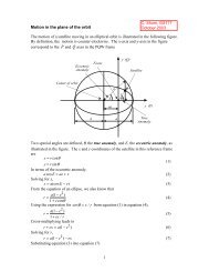
From Figure 2.3, which shows the earth-fixed reference frame XYZ (the<br />
X-axis in the equatorial plane crossing the upper branch <strong>of</strong> the Greenwich<br />
meridian), one obtains from spherical geometry in the position triangle<br />
NPD <strong>for</strong> the zenith distance £ <strong>of</strong> [e.g., Melchior, 1966]:<br />
© £¤ !"#©$ ©%!&©('<br />
(2.10)<br />
where ) and<br />
<br />
are geocentric (east) longitude and latitude, respectively,<br />
where<br />
!<br />
is the declination <strong>of</strong> , and where )+*,)(- defines the hour angle H<br />
<strong>of</strong> the tide-generating body D (Figure 2.3):<br />
' ¤ )+*,)%- (2.11)<br />
The hour angle is measured from the upper branch <strong>of</strong> the observer’s<br />
meridian and positive to the west <strong>of</strong> the observer. With expression (2.10),<br />
the addition <strong>for</strong>mula <strong>for</strong> &.0/ © £©1<br />
can be derived [e.g., Hobson, 1965]:<br />
© £©1+¤ . 3<br />
46587 /09:* ! 7;4 1 /=*@ 1BA<br />
/=< " 1BA 2.4 / C 1 2.4 / D! 1 © '<br />
(2.12)<br />
2.0/
§<br />
<br />
<br />
<br />
<br />
<br />
<br />
' &<br />
<br />
<br />
<br />
M<br />
<br />
<br />
')(+* , &<br />
<br />
D<br />
&<br />
¥<br />
¥<br />
¥<br />
"<br />
§<br />
<br />
<br />
¨<br />
8;:=
¦<br />
¥<br />
2.3 The tidal species 11<br />
earth’s polar axis<br />
high tide<br />
high tide<br />
¢¡ ¤£<br />
equator<br />
tidal bulge<br />
Figure 2.4 Diurnal inequality due to the declination § <strong>of</strong> the tide-generating body ¨ .<br />
Because the earth rotates around its polar axis in one day, while the<br />
sun and the moon complete one orbit around the earth in<br />
¡¡<br />
respectively one<br />
year and one ©<br />
month, <br />
the term containing will show variations <strong>of</strong><br />
approximately 12 hours, i.e. twice a day. Hence, this term is<br />
¡£<br />
called the<br />
semi-diurnal species. ©<br />
Similarly, <br />
the term containing will show once<br />
a day variations and there<strong>for</strong>e is called the diurnal species. The diurnal<br />
variations can be explained with the aid <strong>of</strong> Figure 2.4. Due to the <strong>of</strong>fset <strong>of</strong><br />
the bulge relative to the equator, an observer facing the tide-generating<br />
body will experience a higher tide £ than observer on opposite side <strong>of</strong><br />
their meridian. Half a day later, when the earth has ¡ rotated through ,<br />
positions are reversed, so that any observer rotating with the earth will<br />
notice a diurnal inequality in the tide, which is expressed by<br />
¡<br />
the diurnal<br />
species in ©<br />
(2.15). The <br />
term from which is absent shows variations<br />
with the square <strong>of</strong> the sine <strong>of</strong> the tide-generating body’s declination and<br />
thus has a period <strong>of</strong> half a year <strong>for</strong> the sun and half a month in case <strong>of</strong><br />
the moon assuming constant (effects <strong>of</strong> variations in are discussed<br />
in Sections 2.6 and 2.7). Hence, it is called the long-period species. The<br />
periods <strong>of</strong> half a month and half a year can be explained by the fact that<br />
the same configuration will be reached when the sun and the moon are<br />
#"<br />
at<br />
their maximum and minimum declinations <strong>of</strong> and ,<br />
respectively.<br />
Notice that the ¦ declination will cause the magnitudes <strong>of</strong> the ¦!<br />
three<br />
types <strong>of</strong> tides (2.15) to vary with the positions <strong>of</strong> the sun and the moon<br />
in their orbits. An increasing value <strong>of</strong> the declination, either in a positive<br />
¦
©<br />
12 The tide-generating <strong>for</strong>ce<br />
or a negative sense, amplifies the diurnal species at the expense <strong>of</strong> the<br />
semi-diurnal and long-period species, which both become smaller. Notice<br />
also that if the orbit <strong>of</strong> the moon and the apparent orbit <strong>of</strong> the sun were<br />
to lie in the earth’s equatorial plane (zero declination), the tide all over<br />
the globe would be the sum <strong>of</strong> a periodic semi-diurnal tide ¥§¦<br />
(varying with<br />
¢¡¤£<br />
latitude according to ) superimposed on a permanent ¥ tide ¦§<br />
(varying<br />
with ¨ © £<br />
latitude according to ). The permanent tide is due to<br />
the asymmetry <strong>of</strong> the tidal bulge, i.e. at a certain latitude, high tide and<br />
low tide are not <strong>of</strong> equal magnitude as expressed by ¨<br />
the constant term<br />
in (2.7).<br />
2.4 The equilibrium theory <strong>of</strong> tides<br />
With the equilibrium theory, as well as with the dynamic theory to be discussed<br />
in Section 3.3, we seek an expression <strong>for</strong> the vertical displacement<br />
<strong>of</strong> the sea surface as caused by the tractive <strong>for</strong>ces, i.e. the ocean tide. In<br />
the equilibrium theory as originally established by Sir Isaac Newton in<br />
1678, the hypothesis is that the earth is <strong>for</strong>med <strong>of</strong> a rigid spherical core<br />
completely covered with a thin layer <strong>of</strong> water without either viscosity or<br />
inertia [e.g., Franco, 1981; Pugh, 1987]. For such an earth, the sea surface<br />
would respond instantaneously to the tractive <strong>for</strong>ces adapting itself to an<br />
equipotential surface [e.g., Pond and Pickard, 1983]. On this surface, all acting<br />
<strong>for</strong>ces are in equilibrium (Figure 2.5). In the vertical direction we have<br />
hydrostatic equilibrium while in the horizontal direction, the tractive <strong>for</strong>ce<br />
is being balanced by the horizontal pressure gradient <strong>for</strong>ce resulting from<br />
the slope <strong>of</strong> the water surface [e.g., Pond and Pickard, 1983]. The de<strong>for</strong>med<br />
sea surface in Figure 2.5 will thus be normal to the combined <strong>for</strong>ce <strong>of</strong> gravity<br />
and the tractive <strong>for</strong>ce.<br />
The vertical <br />
displacement <strong>of</strong> a water particle initially at rest at the<br />
sea surface may be found by applying the work theorem [e.g., Schureman,<br />
1971]. This theorem states that to rise from its rest position (unde<strong>for</strong>med<br />
surface in Figure 2.5), where the potential (in our case the earth’s gravity<br />
potential) is unperturbed, to the position where the potential has been perturbed<br />
by addition <strong>of</strong> the tide-generating potential (de<strong>for</strong>med surface),<br />
a water particle has to move a vertical distance given by:<br />
<br />
<br />
(2.16)<br />
where is the earth’s mean gravity. Equation (2.16) is known as Bruns’<br />
<strong>for</strong>mula [Heiskanen and Moritz, 1967; Moritz and Müller, 1988] in which the<br />
tide-generating potential acts as the disturbing potential.<br />
For several reasons it is unrealistic to assume that the ocean tide will<br />
follow an equilibrium response (2.16). First <strong>of</strong> all, because the tidegenerating<br />
<strong>for</strong>ce is not the result <strong>of</strong> a central <strong>for</strong>ce field originating from<br />
the center <strong>of</strong> the earth, the movement <strong>of</strong> the water particles is not strictly
£<br />
2.4 The equilibrium theory <strong>of</strong> tides 13<br />
pressure gradient <strong>for</strong>ce<br />
de<strong>for</strong>med surface<br />
¢¡<br />
gravity<br />
tractive<br />
<strong>for</strong>ce<br />
unde<strong>for</strong>med surface<br />
Figure 2.5 Concept <strong>of</strong> the equilibrium tide ¤ .<br />
vertical but also includes the horizontal flow <strong>of</strong> tidal currents [e.g., Schureman,<br />
1971; Dietrich et al., 1975]. However, if we are not interested in the<br />
actual motion <strong>of</strong> the water particles but only in the envelope <strong>of</strong> the displacement<br />
field, i.e. the resulting shape <strong>of</strong> the earth’s surface, the equilibrium<br />
theory does provide an order <strong>of</strong> magnitude approximation <strong>of</strong> the actual<br />
ocean tide [Lambeck, 1988]. Secondly, the earth is not entirely covered<br />
with water and the propagation <strong>of</strong> the tidal waves (each harmonic term<br />
in the spectrum <strong>of</strong> ¥ or £ is called a tidal harmonic or tidal wave) in an<br />
east-west direction is impeded by the continental boundaries [Pugh, 1987].<br />
Thirdly, the solid earth underneath the oceans is not at all rigid and so de<strong>for</strong>ms<br />
under the tide-generating <strong>for</strong>ces. Because the ocean tide by definition<br />
is the vertical displacement <strong>of</strong> the sea level above the moving ocean floor,<br />
(2.16) has to be corrected <strong>for</strong> the effects <strong>of</strong> the bottom tide, i.e. the tidal<br />
motion <strong>of</strong> the ocean floor, as will be discussed in Section 3.3. Fourthly, the<br />
equilibrium state in Figure 2.5 will only be achieved if the <strong>for</strong>cing periods<br />
<strong>of</strong> the sun and the moon are much larger than the resonance periods <strong>of</strong><br />
the oceans [e.g., Munk and MacDonald, 1975; Lambeck, 1988]. In that case,<br />
the tidal elevations are effectively instantaneous and are given by static<br />
(i.e. equilibrium) considerations. On the other hand, if the <strong>for</strong>cing periods<br />
are comparable to the resonance periods, the ocean’s response to the<br />
tidal <strong>for</strong>cing will be dynamic. Analyses <strong>of</strong> tide gauge records seem to indicate<br />
that the oceans as a whole are at near resonance at diurnal and semidiurnal<br />
periods [Pugh, 1987]. This means that the amplitudes <strong>of</strong> the diurnal<br />
and semi-diurnal tidal harmonics will, in general, be larger than their<br />
predicted equilibrium values, while we also have to account <strong>for</strong> a phase<br />
lag <strong>of</strong> these harmonics on their <strong>for</strong>cing terms in the tide-generating poten-
14 The tide-generating <strong>for</strong>ce<br />
tial due to the inertia <strong>of</strong> the oceans. The long-period tides, <strong>of</strong> which the<br />
most important have a period <strong>of</strong> half a month or longer, may be expected<br />
to closely follow the equilibrium theory [e.g., Lambeck, 1988], although definite<br />
departures from equilibrium have been observed [e.g., Cartwright and<br />
Ray, 1990a]. Fifthly, the various ocean basins each have their individual<br />
shape and depth and there<strong>for</strong>e their individual resonance periods [Pond<br />
and Pickard, 1983]. Each ocean basin, there<strong>for</strong>e, responds differently to a<br />
harmonic term <strong>of</strong> the tidal <strong>for</strong>cing, so that the generated tide has an amplitude<br />
and phase lag that will depend on the location [Pond and Pickard,<br />
1983; Pugh, 1987]. For the above reasons it is obvious that the actual ocean<br />
tide will bear little resemblance to the equilibrium tide. Still, in spite <strong>of</strong><br />
its limited ability to model the ocean tide, the equilibrium tide does serve<br />
as an important reference in tidal analysis, e.g. as input values <strong>for</strong> the response<br />
method (Section 3.5).<br />
2.5 The sun-earth-moon system<br />
To facilitate the harmonic development <strong>of</strong> the tide-generating potential<br />
in Section 2.6, it is useful to discuss here the orbit <strong>of</strong> the moon around<br />
the earth and the apparent orbit <strong>of</strong> the sun. In the discussion that<br />
follows, Figure 2.6 is used as a reference. The positions <strong>of</strong> the sun and<br />
the moon are both described with respect to the ecliptic, i.e. the plane<br />
<strong>of</strong> the sun’s apparent orbit around the earth, in terms <strong>of</strong> ecliptic longitude,<br />
ecliptic latitude, and the distance earth-sun or earth-moon [Roy,<br />
1965; Seidelmann, 1992]. Longitude in the ecliptic is measured from the<br />
vernal equinox , which is the point on the equinox line (intersection <strong>of</strong><br />
the earth’s equator and the ecliptic) when the sun crosses the equatorial<br />
plane on 21 March. Latitude is measured with respect to the ecliptic plane.<br />
The motion <strong>of</strong> the sun (apparent orbit) takes place in the ecliptic.<br />
The ecliptic is inclined to the equator at an angle <strong>of</strong> ¡£¢¥¤¦ §¨¢ about , known<br />
as the obliquity <strong>of</strong> the © ecliptic . The mean eccentricity <strong>of</strong> the solar orbit<br />
is 0.017 and the average sun-earth distance §¨¦¨ is km [Roy, 1965].<br />
The ascending node <strong>of</strong> the sun makes one revolution in the ecliptic plane<br />
in about 26,000 years (luni-solar precession), while the line <strong>of</strong> apses has a<br />
period <strong>of</strong> approximately 21,000 years due to planetary perturbations [Roy,<br />
1965].<br />
In case <strong>of</strong> the moon, the orbit has a mean eccentricity <strong>of</strong> 0.055 and<br />
a mean distance to the earth <strong>of</strong> 384,400 km [Roy, 1965]. Mainly due to<br />
solar perturbations, the eccentricity <strong>of</strong> the lunar orbit varies between<br />
0.044 and 0.067, while its inclination relative to the ecliptic (Figure 2.6)<br />
oscillates ¤¦ between ¤¦ ¢ and (mean inclination ¤¦ is ). In contrast with<br />
artificial earth satellites, the solar perturbations dominate the earth’s<br />
perturbing effect on the lunar orbit. As a consequence, the motion <strong>of</strong><br />
the ascending lunar node takes primarily place in the ecliptic and
¡<br />
¤<br />
2.5 The sun-earth-moon system 15<br />
lunar orbit<br />
moon<br />
sun<br />
ecliptic (plane <strong>of</strong><br />
sun’s apparent orbit)<br />
earth<br />
equator<br />
¢ £<br />
Figure 2.6 Orbits <strong>of</strong> the sun and the moon.<br />
not in the equatorial plane [Seidelmann, 1992]. The motion <strong>of</strong> the lunar<br />
node is due to the differential <strong>for</strong>ce between the attraction <strong>of</strong> the sun<br />
on the earth-moon system as a whole and the attraction <strong>of</strong> the sun on<br />
the moon [e.g., Seidelmann, 1992]. This differential <strong>for</strong>ce, its action being<br />
much similar to the concept <strong>of</strong> the tide-generating <strong>for</strong>ce, causes the lunar<br />
node to undergo a practically uni<strong>for</strong>m change in time along the ecliptic<br />
in a westward direction (regression). As a consequence, the inclination<br />
<strong>of</strong> the moon’s orbit £ relative to the equator changes with the position<br />
<strong>of</strong> the moon’s node from approximately ¥§¦©¨ , when the ascending node<br />
coincides with the vernal equinox, to about ¦©¨ , when the ascending<br />
node coincides with the autumnal equinox (23 September) opposite to .<br />
The time between two passages <strong>of</strong> the lunar node with the vernal equinox<br />
is 18.61 years. The solar perturbations also cause a practically uni<strong>for</strong>m<br />
motion <strong>of</strong> the moon’s line <strong>of</strong> apses, which takes place in the plane <strong>of</strong> the<br />
lunar orbit with a period <strong>of</strong> 8.85 years. The inclination <strong>of</strong> the lunar orbit<br />
relative to the ecliptic and the lunar eccentricity do not suffer a secular<br />
motion and may be assumed constant (usually mean values are adopted).<br />
As mentioned in, e.g., Doodson [1921] and Valorge [1995], the position<br />
<strong>of</strong> the moon may be obtained from E. W. Brown’s lunar theory (1905),
¡<br />
3 &4. & 3 56! 7#%% '# ( % *# +<br />
£2<br />
&, &,9&*#%% 6*#)()% '#)+<br />
¢8¤7!<br />
¡<br />
16 The tide-generating <strong>for</strong>ce<br />
mean longitude <strong>of</strong> symbol period<br />
moon 27.32 mean solar days<br />
sun<br />
365.24 mean solar days<br />
lunar perigee ¢ 8.85 tropical years<br />
lunar node £ 18.61 tropical years<br />
solar perigee ¢¥¤ 21,000 tropical years<br />
Table 2.1 Fundamental angles that describe the motion <strong>of</strong> the sun and the moon in the sunearth-moon<br />
system. For the definitions <strong>of</strong> the mean solar day and the tropical<br />
year, the text may be referred to.<br />
which includes the perturbing effects <strong>of</strong> the sun, the earth, and the other<br />
planets on the lunar orbit. With this theory, the position <strong>of</strong> the moon<br />
is given in ecliptic longitude, ecliptic latitude, and the<br />
§©¨§©¨<br />
dimensionless<br />
distance , where the actual lunar distance is substituted <strong>for</strong> and<br />
¦<br />
the mean lunar distance §¨ §©¨<br />
<strong>for</strong> . For the sun’s apparent position, ¦<br />
expressions<br />
<strong>for</strong> its ecliptic longitude and dimensionless distance are provided<br />
by S. Newcomb’s solar theory (1895). With this theory, the sun’s ecliptic<br />
latitude is assumed to be zero while the eccentricity <strong>of</strong> the sun’s apparent<br />
orbit is kept fixed [e.g., Doodson, 1921; Valorge, 1995]. For the sun as well<br />
as <strong>for</strong> the moon, each <strong>of</strong> the ecliptic coordinates can be expressed in terms<br />
<strong>of</strong> five fundamental angles that by good approximation proceed linearly<br />
with time. These fundamental angles describe the long-term motion <strong>of</strong><br />
the sun and the moon, i.e. with periodic variations <strong>of</strong> motion removed.<br />
In Table 2.1, the fundamental angles with their symbols and periods<br />
are given. All <strong>of</strong> these angles are longitudinal angles and there<strong>for</strong>e are<br />
measured in the ecliptic with respect to the vernal equinox. The angles<br />
belong to five fictive bodies that move along the ecliptic with practically<br />
uni<strong>for</strong>m speed and at a constant distance from the earth. For instance, the<br />
mean longitude <strong>of</strong> the moon measures the longitude <strong>of</strong> a fictive moon<br />
traveling in the ecliptic at an angular speed <strong>of</strong> per 27.32 mean solar<br />
days. The exact definition <strong>of</strong> the mean solar day will be given below.<br />
From Newcomb’s theory <strong>for</strong> the solar elements ¡ and ¢¥¤ , and similar<br />
expressions obtained by Brown in 1919 <strong>for</strong> the lunar elements , ¢ and<br />
£ , the following expressions are given <strong>for</strong> the five fundamental angles<br />
[Doodson, 1921; Melchior, 1966; Casotto, 1989]:<br />
! " $#%% ! &'#)()% *#)+<br />
<br />
,$#%% '#)(<br />
<br />
(2.17)<br />
¢-% <br />
'#/.0 ! &*#)(1.0 ! &'#)+<br />
# where is in Julian centuries (a Julian century consists <strong>of</strong> 36,525 mean<br />
solar days) from 31 December 1899, 12 hr. Universal Time (UT). Notice<br />
that besides the linear terms, the above expressions also contain higher-
¨<br />
¤<br />
¨<br />
©<br />
¥<br />
¦<br />
¢<br />
¡<br />
<br />
<br />
§<br />
2.5 The sun-earth-moon system 17<br />
equator<br />
Greenwich<br />
£ ¡<br />
<br />
<br />
<br />
<br />
Figure 2.7 Concepts <strong>of</strong> the mean sun and the mean moon , which define mean solar<br />
time and mean lunar time, respectively. Denoted by and are Greenwich mean<br />
solar time and Greenwich mean lunar time, respectively, whereas and<br />
are local mean solar time and local mean lunar time, respectively.<br />
order terms in . This is because the theories <strong>of</strong> Newcomb and Brown<br />
describe the long-term motions <strong>of</strong> the sun and the moon. Because these<br />
long-term motions do not only suffer a linear change, terms <strong>of</strong> higher<br />
order than arise as well. The higher-order terms are mainly due to the<br />
planetary perturbations on the eccentricity <strong>of</strong> the moon’s orbit and on the<br />
eccentricity <strong>of</strong> the sun’s apparent orbit [Roy, 1965].<br />
It may be interesting to note that civil time, i.e. UT, is based on the<br />
motion <strong>of</strong> the so-called mean sun (Figure 2.7). The mean sun is defined to<br />
move along the equator at a constant speed, which equals that <strong>of</strong> the fictive<br />
sun, i.e. , at a certain reference time [Franco, 1981]. Hence, over a <br />
period<br />
<strong>of</strong> many centuries (according to <br />
¨<br />
(2.17), varies with /century per<br />
century), the right ascension (i.e. longitude measured along the equator<br />
from the vernal equinox) <strong>of</strong> the mean sun may be taken equal to the mean<br />
longitude <strong>of</strong> the fictive sun in the ecliptic, if we use as a common<br />
¤<br />
¨
¡<br />
<br />
18 The tide-generating <strong>for</strong>ce<br />
reference point [Schureman, 1971; Franco, 1981]. In a similar way, we may<br />
define the mean moon (Figure 2.7), which moves along the equator with<br />
the same speed as the fictive moon at a reference time. Hence, at any<br />
instant, the right ascension <strong>of</strong> the mean moon (in the equatorial plane) will<br />
be equal to the mean longitude <strong>of</strong> the fictive moon (in the ecliptic). The<br />
time elapsed between two passages <strong>of</strong> the mean sun with the Greenwich<br />
meridian, i.e. the earth’s sidereal rotation relative to the motion <strong>of</strong> the<br />
mean sun, is called a mean solar day (one sidereal day equals 0.997 mean<br />
solar days). Similarly, the time between two passages <strong>of</strong> the mean moon<br />
with the Greenwich meridian is called a mean lunar day, which equals<br />
1.035 mean solar days. The time between two passages <strong>of</strong> the mean sun<br />
with the vernal equinox is called the tropical year, which equals 365.24<br />
mean solar days. The mean solar day and the tropical year are the units <strong>of</strong><br />
time that we are accustomed with in civil life.<br />
In Figure 2.7, the angle between the lower branch <strong>of</strong> the Greenwich<br />
meridian and the mean sun denotes Greenwich mean solar time ¡ or Universal<br />
Time UT (notice that defines the sidereal day). The angle <strong>of</strong> the<br />
mean moon counted from the lower branch <strong>of</strong> the Greenwich ¡£¢¥¤<br />
meridian is<br />
Greenwich ¦ mean lunar time . Figure 2.7 is perhaps easiest interpreted by<br />
imagining the observer P to be fixed in space. Then, denoting the earth’s<br />
§©¨ sidereal rotation by , <br />
the vernal equinox , <br />
the mean sun , and the<br />
mean moon , move in a clockwise direction with respective <br />
speeds <strong>of</strong><br />
¤<br />
, , §¨ and . Notice from Figure 2.7 that local mean solar §¨ time<br />
§¨<br />
and local mean lunar time <strong>of</strong> an observer P are obtained by adding the observer’s<br />
longitude to ¦ and , respectively. Also notice from Figure 2.7<br />
<br />
that ¡ the relation:<br />
¢¤<br />
(2.18)<br />
¦<br />
between mean solar time and mean lunar time must hold.<br />
2.6 Harmonic development <strong>of</strong> the tide-generating<br />
potential<br />
In the previous section it was shown that the orbital motions <strong>of</strong> the sun<br />
and the moon around the earth can be described by five angles that by<br />
good approximation proceed linearly with time. This implies that the tidegenerating<br />
potential can be developed into a series <strong>of</strong> harmonic functions.<br />
The amplitudes <strong>of</strong> these harmonics may be considered as constant over a<br />
period <strong>of</strong> centuries, while their arguments are linear combinations <strong>of</strong> the<br />
five fundamental angles and there<strong>for</strong>e vary at an almost linear rate. In<br />
1867, Sir G. H. Darwin was the first to actually carry out such a development.<br />
Although, Darwin’s expansion was limited to include 39 terms<br />
[Munk and Cartwright, 1966], the names he assigned to these terms are still<br />
widely used in tidal analysis. One <strong>of</strong> the most comprehensive developments<br />
<strong>of</strong> the tide-generating potential is due to Doodson [1921]. The Doo-
! <br />
$ <br />
,<br />
$<br />
<br />
<br />
$ <br />
,<br />
$<br />
,<br />
$ !<br />
(<br />
<br />
#<br />
&<br />
<br />
L<br />
$<br />
$<br />
,<br />
3<br />
2.6 Harmonic development <strong>of</strong> the tide-generating potential 19<br />
dson expansion, which contains over 400 terms, is carried out over all five<br />
fundamental ¢¡¤£¦¥§£¢¨©££¢¨ angles . As a sixth angle, Doodson used Greenwich<br />
mean lunar time (Section 2.5) to relate the orbital motions <strong>of</strong> the<br />
sun and the moon described in inertial space to the earth-fixed reference<br />
frame <strong>of</strong> the observer [Doodson, 1921].<br />
Important to realize is that when using the harmonic method <strong>for</strong><br />
the analysis <strong>of</strong> tidal data, a problem arises that cannot be corrected <strong>for</strong><br />
by a complete expansion like Doodson’s. For most tide gauge stations<br />
in the open oceans, records are available <strong>for</strong> periods <strong>of</strong> a few years or<br />
less. There<strong>for</strong>e, it is impractical to try to resolve tidal harmonics from<br />
the data that differ by less than one cycle per year in frequency. This is<br />
especially true with altimetry where ocean tides may alias to nearly the<br />
same period (Section 4.4). As the period <strong>of</strong> the mean longitude <strong>of</strong> the<br />
¥ sun is one year, the data are analyzed with harmonics <strong>of</strong> which the<br />
arguments in the expansion differ £¦¡¤£¦¥ in , i.e. harmonics that differ<br />
¨©££¢¨ in are treated as one single term [e.g., Munk and Cartwright,<br />
1966; Schureman, 1971]. The dominant effect <strong>of</strong> the ¨©££¢¨ angles is the<br />
varying inclination <strong>of</strong> the lunar orbit due to the regression <strong>of</strong> its node<br />
. This effect can be accounted <strong>for</strong> with slow varying functions <strong>of</strong> in<br />
<br />
the coefficients and arguments <strong>of</strong> the dominant harmonics [e.g., Melchior,<br />
1966; Schureman, 1971]. Hence, the brief explanation in this section <strong>of</strong> how<br />
the tide-generating potential is developed into a series <strong>of</strong> harmonics, will<br />
only extend to a splitting <strong>of</strong> the arguments in terms <strong>of</strong> ¡ , ¥ and .<br />
To expand the tide-generating potential into its harmonics, (2.15) <strong>for</strong><br />
the sun or the moon is written as:<br />
#%$ "<br />
,<br />
3<br />
<br />
<br />
#%$ & ')(+*<br />
¢-/.10¤2<br />
.10¤2465879(+*;:<br />
¢-/2=@4<br />
.10¤25<br />
3<br />
ED (2.19)<br />
4<br />
4 2= ACB<br />
" #%$<br />
F<br />
(+*<br />
(<br />
$K# A¤HJI<br />
where is the disturber’s mean distance to the earth and the superscript<br />
on the pertains to the tidal species <strong>of</strong> . For the sake <strong>of</strong> brevity,<br />
some definitions according to Doodson [1921] have been introduced. Denoted<br />
by will be the disturber’s general coefficient, which is defined<br />
as:<br />
$ (2.20)<br />
79(+*<br />
¢-1<br />
$G<br />
M "<br />
For the moon and the sun, the general coefficients are usually given the<br />
( symbols (N and , respectively, where the <strong>for</strong>mer has also become known<br />
as Doodson’s tidal constant [e.g., Melchior, 1966]. The general coefficients<br />
appear in the (O* ¢- terms in (2.19). These terms, which involve functions<br />
<strong>of</strong> the observer’s - latitude multiplied ( by , are called Doodson’s<br />
geodetic coefficients (<strong>of</strong> P 4 degree ) [Doodson, 1921]. In case <strong>of</strong> the moon,
9<br />
<br />
1<br />
9<br />
£<br />
<br />
¡<br />
9<br />
9<br />
1<br />
<br />
£<br />
¨<br />
<br />
<br />
1<br />
9<br />
9<br />
<br />
<br />
20 The tide-generating <strong>for</strong>ce<br />
they will be denoted ¢¡ £¥¤§¦©¨ by , and in case <strong>of</strong> the sun ¢¡ £¥¤ by<br />
moon, the geodetic coefficients <strong>for</strong> read:<br />
¦©¨ . For the<br />
(2.21)<br />
¦ "!#%$<br />
¡¤¦©¨<br />
¨<br />
¡ ¤ ¦©¨& '!#%$()¨<br />
¤ ¦©¨& '*,+)!<br />
The expressions <strong>for</strong> the geodetic coefficients <strong>of</strong> the sun are the same as<br />
those <strong>for</strong> the moon except that is replaced by . Notice that a factor<br />
is ¡¤ brought into so that all geodetic coefficients <strong>of</strong> the moon have as<br />
a maximum. Because the aim <strong>of</strong> the harmonic development is to<br />
.0/,12.0/<br />
expand<br />
the functions in (2.19) that -<br />
depend 3 on , 4 , and into a series <strong>of</strong> harmonics,<br />
this means that all coefficients <strong>of</strong> the harmonic development will<br />
be normalized with respect to one and the same quantity , if we write the<br />
geodetic coefficients <strong>of</strong> the sun as times those <strong>of</strong> the moon and absorb<br />
<br />
the factor in the coefficients <strong>of</strong> the solar harmonics. In this way,<br />
the values <strong>of</strong> the harmonic coefficients give their relative importance [Doodson,<br />
1921]. To proceed, 5 <br />
each species <strong>of</strong> the tide-generating potential<br />
<strong>of</strong> the moon and the sun is written to a <strong>for</strong>m:<br />
9A@ BC9@ DFE<br />
5 <br />
¡ where are the geodetic coefficients <strong>of</strong> the moon. = The are the coefficients<br />
<strong>of</strong> the harmonic <br />
development (containing in case <strong>of</strong> the solar<br />
£¥¤¦©¨<br />
harmonics), while the G summation over is over all harmonic terms <strong>of</strong> the<br />
species. <br />
The arguments are the astronomical arguments or Doodson<br />
arguments at Greenwich because H the angle in these arguments is 9@IDFE<br />
mean<br />
lunar time (<br />
at Greenwich is called the local argument because it @JE<br />
is<br />
related to local mean H lunar time in Figure 2.7):<br />
6 ¡ £¥¤ ¦©¨87:9¦©<br />
(2.22)<br />
@IO¢PQ@IRTS@IUWVT@IXTY[Z)@I\]V<br />
M where to are integer numbers. By convenience, Doodson defined the<br />
\<br />
negative <strong>of</strong> as , so that all angles in (2.23) increase towards the east<br />
[Doodson, 1921]. The Y<br />
are so-called additive phase corrections, which are<br />
multiples <strong>of</strong> Y . These phase corrections are needed to achieve uni<strong>for</strong>mity<br />
B^9<br />
Z _)`)a<br />
in the harmonic series, i.e. to obtain a series (2.22) <strong>of</strong> all positive coefficients<br />
and cosine functions only [Schureman, 1971; Cartwright, 1993; Casotto,<br />
; = ;<br />
1989]. This procedure is known as the Doodson & Warburg convention,<br />
which is detailed in e.g. Casotto [1989].<br />
For the most important tides, the outcome <strong>of</strong> the harmonic development<br />
up to a yearly splitting in frequency, i.e. <br />
no two arguments in the<br />
harmonic development are the same H with regard to , , and , may be<br />
shown to give <strong>for</strong> the long-period P S species , the diurnal 5 species , and<br />
5<br />
(2.23)<br />
¦LKANM(H
6<br />
<br />
<br />
<br />
¡<br />
L<br />
%<br />
5<br />
5<br />
<br />
¡<br />
<br />
¡<br />
%<br />
%<br />
%<br />
%<br />
%<br />
%<br />
%<br />
<br />
<br />
.<br />
.<br />
%<br />
%<br />
.<br />
<br />
%<br />
%<br />
%<br />
.<br />
<br />
<br />
.<br />
<br />
.<br />
<br />
.<br />
5<br />
<br />
5<br />
5<br />
<br />
<br />
I<br />
%<br />
&<br />
F<br />
F<br />
5<br />
5<br />
5<br />
5<br />
I<br />
<br />
5<br />
5<br />
5<br />
<br />
5<br />
5<br />
5<br />
5<br />
W<br />
b<br />
g<br />
#<br />
l<br />
#<br />
m<br />
B<br />
¥<br />
¥<br />
J<br />
J<br />
¡<br />
¡<br />
¡<br />
¡<br />
J<br />
J<br />
¡<br />
¡<br />
¡<br />
¡<br />
<br />
<br />
<br />
<br />
<br />
<br />
<br />
<br />
<br />
<br />
<br />
<br />
<br />
<br />
<br />
<br />
<br />
<br />
<br />
<br />
2.7 The Doodson classification <strong>of</strong> tides 21<br />
the semi-diurnal species ¢¡£¡ [Doodson, 1921; Schureman, 1971]:<br />
¥<br />
¤¡£¥§¦ ¨©<br />
<br />
$#<br />
¡ ¡! "<br />
/.<br />
$#<br />
/5).<br />
576<br />
$#<br />
%'&)(+*-, <br />
10 £2 "43<br />
% ¡ *-, <br />
"98<br />
%;:=<<br />
:<br />
/F<br />
¡ ¡>@A! B<br />
BC<br />
%'&)(ED*-, <br />
10 D £2<br />
BHG<br />
BC<br />
5)F§I<br />
%;:=<<br />
:<br />
BC<br />
(2.24)<br />
¡> *-, <br />
B D G<br />
J/<br />
ON<br />
576<br />
$#<br />
¤¡JC¦<br />
¨©<br />
*-, ¡CK ¡ML<br />
*-, <br />
P)Q)R %<br />
TS %VU <br />
ON<br />
5).<br />
576<br />
$#<br />
(+*-, <br />
% 0TP)Q)R %<br />
TS %VU ZY [<br />
%;X<br />
¡<br />
ON<br />
$#<br />
ON<br />
5)F<br />
% J<br />
<br />
*-, <br />
% P)Q)R\]S %VU ^1_<br />
%;:=<<br />
:<br />
> *-, ¡a`<br />
*-, <br />
P)Q)R %VU <br />
BC<br />
ON<br />
:=< %<br />
:<br />
J<br />
¡<br />
^ed BC<br />
J<br />
(2.25)<br />
<br />
> *-, <br />
% P)Q)R %cU <br />
¡<br />
/57N<br />
576<br />
$#<br />
¤¡£¡§¦ ¨©<br />
*-, f K ¡ML<br />
*-, <br />
S %<br />
U "<br />
/57N<br />
576<br />
$#<br />
(+*-, <br />
% 0 %<br />
S %<br />
U <br />
%;X<br />
¡<br />
/57N<br />
576<br />
$#<br />
J %<br />
¡<br />
(+*-, <br />
h0 % Ei Q)R %<br />
S %<br />
U ZY<br />
/57N<br />
5).<br />
$#<br />
J %<br />
¡<br />
¡ *-, <br />
S %<br />
U <br />
^1_<br />
/57N<br />
$#<br />
(+*-, <br />
% 0<br />
S %<br />
U ZY<br />
/57N<br />
5).<br />
5)F<br />
%;:=<<br />
:<br />
jf ` *-,<br />
L ¡<br />
*-, <br />
U <br />
BC<br />
/57N<br />
5).<br />
(ED*-, <br />
% 0 Dk%<br />
U <br />
BC<br />
%;X<br />
¡<br />
/57N<br />
5).<br />
J %<br />
¡<br />
(ED*-, <br />
10 Dk% Ei Q)R %<br />
U ZY<br />
BC<br />
/57N<br />
5).<br />
%;:=<<br />
:<br />
J<br />
¡<br />
^ed BC<br />
¡<br />
(2.26)<br />
where and are angles that depend on the lunar node as explained in<br />
Schureman S<br />
[1971]. Denoted by and are the mean eccentricity <strong>of</strong> the<br />
lunar orbit and the apparent solar orbit, respectively. In the above equations,<br />
all terms <strong>of</strong> the ( order (7D <strong>of</strong> and have been neglected. Each tide in<br />
the above equations is referred to by its Darwin name and by its origin,<br />
i.e. (L)unar or (S)olar. A brief explanation <strong>of</strong> each <strong>of</strong> the terms in (2.24) to<br />
( ¡ ( ¡D<br />
(2.26) will be given in the next section.<br />
¡> *-, <br />
U
§<br />
§<br />
<br />
<br />
<br />
<br />
22 The tide-generating <strong>for</strong>ce<br />
2.7 The Doodson classification <strong>of</strong> tides<br />
Because the names Darwin used to classify the tides are confined to a<br />
limited number, a more systematic notation was introduced by Doodson.<br />
Each tide is denoted by a 6-digit number, known as the Doodson<br />
¢¡£ ¥¤¦ ¨§© ¨ ¨© ¨<br />
number,<br />
. The Doodson number is obtained by adding 055.555 to<br />
the argument <br />
number in (2.23):<br />
¢<br />
¥¤ ¨§© ¨ ¨ ¨¡<br />
"!$#¨%& '!$#¨% !$#¨%& !$#¨%&<br />
<br />
Because the integers to are rarely outside the range -4 to 4, adding<br />
055.555 to the argument number makes that the Doodson numbers are<br />
always positive [Doodson, 1921]. With (2.27), the Greenwich astronomical<br />
<br />
argument (2.23) may also be written as:<br />
!$#¨% (2.27)<br />
()<br />
or equivalently:<br />
+*BA% (2.29)<br />
#¨%+73= (2.28)<br />
+*%<br />
¡, ¥¤.-<br />
!/<br />
¨§10<br />
#¨%23!/<br />
¨40<br />
#¨%56!/<br />
30<br />
#¨%+78!/<br />
¨40<br />
#¨%:9<br />
()<br />
where is called the tidal frequency and (C) +*BA% is the astronomical argument<br />
at epoch ><br />
, i.e. at the origin <strong>of</strong> time () : * *BA<br />
+*%<br />
*@!<br />
() ¡, ¥¤ > - ><br />
> ¨@0<br />
2E!D #¨%<br />
> E0<br />
5F!D<br />
> ¨@0<br />
7G!D #¨%<br />
> ¨@0<br />
9 73= (2.30) #¨%<br />
()<br />
¡H ¥¤B-<br />
¨§60<br />
¨60<br />
J0<br />
+*BA©%<br />
+*BA%@!H<br />
#¨%2I+*BA©%@!H<br />
#¨%5E+*BA©%@!H<br />
#¨%+7K+*BA%<br />
¨60 ¨60<br />
#¨%+73=+*BA% (2.31)<br />
!L #¨%:9
;<br />
9<br />
2.7 The Doodson classification <strong>of</strong> tides 23<br />
factor ¢¡ and the nodal angle £¤¡ . Hence, each constituent ¥¦¡¨§©¡¡ in (2.24)<br />
to (2.26) is written as:<br />
¥¡¨§©¡¡ ¦ ¢¡ "! #$¡%!'&)(*+,-¡/.102¡/.1£3¡ 4.1576¤ (2.32)<br />
where 8%9 equals 5 . The amplitude ! #¡%! pertains to the main spectral line<br />
(main harmonic) around which the side lines (smaller harmonics) due to<br />
the modulation <strong>of</strong> the lunar node are centered. For the major constituents,<br />
the Doodson arguments <strong>of</strong> their main lines appear in (2.24) to (2.26), e.g.<br />
the line 255.555 in case <strong>of</strong> the :¡ and nodal angles £¤¡ depend on the<br />
position <strong>of</strong> the lunar node and hence vary slowly with time throughout<br />
an 18.6-year cycle [e.g., Schureman, 1971]. Notice, there<strong>for</strong>e, that the nodal<br />
parameters strictly apply to the lunar constituents.<br />
Considering as a<br />
constant, the solar constituents all have unity as a nodal factor, whereas<br />
their nodal angles are zero by definition. Actually, this means that the<br />
solar constituents in (2.24) to (2.26) are the tidal harmonics themselves.<br />
It should be mentioned that in case a constituent has a lunar and a solar<br />
contribution, @A9 like in (2.25) @B; or in (2.26), the nodal parameters give the<br />
combined effect <strong>of</strong> the lunar and solar parts. Such is easily accomplished<br />
by adding the lunar and solar constituents and writing the combined<br />
constituent to the <strong>for</strong>m (2.32) by which the nodal parameters appear $¡ as<br />
£3¡ and <strong>of</strong> the lunar tide slightly modified by the DCE$ ratio [Schureman,<br />
1971].<br />
In order to avoid confusion between tidal harmonics and tidal constituents<br />
in this thesis, the term F tideG in the context <strong>of</strong> e.g. F the :H; tideG<br />
will be used to denote tidal harmonics. Hence, when we speak <strong>of</strong> the :H;<br />
tide, the main spectral line 255.555 <strong>of</strong> the :H; constituent is understood.<br />
In Table 2.2, the harmonic coefficients and associated equilibrium amplitudes<br />
<strong>of</strong> the Doodson expansion are listed <strong>for</strong> the main tidal lines in the<br />
constituents (2.24) to (2.26). The CTE equilibrium amplitudes pertain to<br />
the expansion <strong>of</strong> Cartwright, Tayler & Edden, which will be discussed<br />
in Section 2.8. The Doodson harmonic ! #I¡%! coefficients (dimensionless<br />
numbers) were taken from Doodson [1921]. Notice that in case <strong>of</strong> the<br />
solar tides, the harmonic coefficients contain the CE$ factor so that the<br />
equilibrium amplitudes <strong>of</strong> all tides are obtained by multiplying ! #I¡J! the<br />
DE¢KLNMPORQ$STT with m [Cartwright and Tayler, 1971]. Also notice that the<br />
equilibrium amplitudes give the extreme values <strong>of</strong> the equilibrium tides,<br />
which occur at latitudes where the corresponding geodetic coefficients<br />
(2.21) become unity. Hence, the semi-diurnal amplitudes are found at the<br />
equator where becomes 1, while the diurnal amplitudes are found<br />
at latitudes UJV$W <strong>of</strong> XYUJV$W and where becomes 1 and -1, respectively.<br />
In case <strong>of</strong> the long-period tides, the equilibrium amplitudes occur at both<br />
the poles, i.e. at latitudes ZMIW <strong>of</strong> X[ZMW and .<br />
In Table 2.2, :
!<br />
8<br />
"<br />
%<br />
(<br />
C<br />
5<br />
)7<br />
265.655<br />
)7<br />
#<br />
272.556<br />
)7<br />
273.555<br />
#<br />
#<br />
#<br />
#<br />
#<br />
#<br />
#<br />
#<br />
#<br />
,<br />
#<br />
#<br />
#<br />
#<br />
<br />
<br />
5<br />
24 The tide-generating <strong>for</strong>ce<br />
Darwin Doodson Doodson harmonic eq. amp. CTE amp. frequency period origin<br />
name number argument coef. ¡£¢¤ ¥ ¡¦¢§ ¨© (m) ¢§ (m) ( /hr.) (days)<br />
<br />
"<br />
$# " <br />
"%<br />
+<br />
055.555 – 0.5046 0.1356 0.0000 ! – permanent<br />
055.555 – 0.2341 0.0629 0.0000 – permanent<br />
0.3146<br />
"<br />
<br />
057.555 0.0730 0.0196 0.0310 0.0821 182.621 declinational<br />
065.455 0.0825 0.0222 0.0352 0.5444 27.555 elliptic<br />
075.555 0.1564 0.0420 0.0666 1.0980 13.661 declinational<br />
<br />
<br />
.-<br />
0.0722 0.0194 0.0502 13.3987 1.120 elliptic <strong>of</strong><br />
0.3769 0.1013 0.2622 13.9430 1.076 principal<br />
163.555 0.1758 0.0473 0.1220 14.9589 1.003 principal<br />
0.3623 0.0974 15.0411 0.997 declinational<br />
0.1682 0.0452 15.0411 0.997 declinational<br />
5<br />
0.3687<br />
32¦<br />
465<br />
BC<br />
245.655 )7'.,<br />
10 ,A3<br />
! DC<br />
)7 255.555 !<br />
0.1739 0.0467 0.1210 28.4397 0.527 major elliptic <strong>of</strong><br />
0.9081 0.2441 0.6320 28.9841 0.518 principal<br />
265.455 )7<br />
5 #@ =<br />
32¦<br />
.C<br />
,$ 0.0257 0.0069 0.0179 29.5285 0.508 ! minor elliptic <strong>of</strong> DC<br />
0.0064 0.0017 0.0045 29.5378 0.508 ! elliptic <strong>of</strong>
-<br />
-<br />
¤<br />
'<br />
-<br />
§<br />
-<br />
+<br />
-<br />
<br />
<br />
-<br />
<br />
-<br />
-<br />
<br />
-<br />
-<br />
¤<br />
-<br />
+<br />
§<br />
<br />
<br />
<br />
2.7 The Doodson classification <strong>of</strong> tides 25<br />
¢¡<br />
(moon, <strong>for</strong>tnightly). For the sun, the period £¥¤ <strong>of</strong> is 182.621 days and its<br />
declinational tide is ¦¨§© called (sun, semi-annual). Due to the ellipticity <strong>of</strong><br />
the lunar orbit and the apparent solar orbit, elliptic tides occur, which are<br />
named (moon, monthly) and ¦© (solar, annual). They are proportional<br />
to the eccentricities <br />
and § , respectively. Their periods are respectively<br />
<br />
governed by the mean longitude <strong>of</strong> the moon relative to lunar perigee, i.e.<br />
, and the mean longitude <strong>of</strong> the sun relative to solar perigee, i.e. ¤<br />
<br />
§ .<br />
<br />
The periods <strong>of</strong> and ¦© are 27.555 days and 365.260 days, respectively.<br />
The diurnal tides all arise directly from the declination <strong>of</strong> the sun and<br />
the moon [e.g., Pugh, 1987]. The two main lunar declinational tides are<br />
<br />
called and . Their arguments are <br />
<br />
and , respectively, so that<br />
they have periods <strong>of</strong> 0.997 days and 1.076 days. Because is the larger<br />
<strong>of</strong> the two, it is termed the lunar diurnal principal tide. The two major<br />
declinational tides <strong>of</strong> the sun are termed and . The argument <strong>of</strong> is<br />
<br />
£¥¤ with a period <strong>of</strong> 1.003 days. For the same reason as the tide <strong>of</strong><br />
!<br />
the moon, is called the solar diurnal principal tide. The tides <strong>of</strong> the<br />
sun and the moon have the same "<br />
argument (<strong>of</strong> which the rate equals<br />
the earth’s sidereal rotation). Hence, they are inseparable and one may<br />
speak <strong>of</strong> the luni-solar tide. Due to the eccentricity <strong>of</strong> the lunar orbit<br />
and <strong>of</strong> the apparent solar orbit, each <strong>of</strong> the declinational tides , , and<br />
, is accompanied by a series <strong>of</strong> elliptic tides that are proportional to or<br />
<br />
. The largest elliptic tide is that <strong>of</strong> . It is called $ and has argument<br />
#§<br />
, while its period is 1.120 days.<br />
%&(')*,+<br />
With the semi-diurnal tides, the principal lunar tide is called<br />
(moon, twice per day). With .-<br />
argument , the period <strong>of</strong> the tide equals<br />
£<br />
0.518 days. The tide is accompanied by a series <strong>of</strong> elliptic tides <strong>of</strong><br />
which the two most important show a symmetry in argument about .-<br />
and there<strong>for</strong>e are denoted by letters in the alphabet on each side <strong>of</strong> , i.e.<br />
¢-<br />
.-<br />
/0-<br />
1<br />
£<br />
2')34,+<br />
1<br />
£<br />
')*,+<br />
¦<br />
£67£ £¥¤<br />
&<br />
8 9<br />
¦<br />
£ £: £ £<br />
;<br />
£¥¤<br />
¢'<br />
<<br />
<<br />
;<br />
£¥¤:<br />
<br />
and . The tide is <strong>of</strong> argument and has a period <strong>of</strong><br />
0.527 days while has argument and a period <strong>of</strong> 0.508 days.<br />
The main solar semi-diurnal tide is called (sun, twice per day). It has<br />
argument and a period <strong>of</strong> exactly half a mean solar day. The<br />
two elliptic tides accompanying are called and with respective<br />
arguments <strong>of</strong> and and periods<br />
<strong>of</strong> 0.499 days and 0.501 days. Denoted by is the semi-diurnal lunar<br />
-<br />
declinational tide. It £=>£<br />
has argument and period <br />
0.499 days.<br />
has a series <strong>of</strong> elliptic tides. One <strong>of</strong> them £<<br />
has argument , which<br />
differs from the elliptic tide <strong>of</strong> by just £ . Hence it is also called .<br />
/5-<br />
The semi-diurnal solar declinational tide is termed /0- . It is inseparable<br />
- <br />
from its <br />
lunar equivalent and hence has same argument and period.<br />
Due to their smallness, the elliptic tides <strong>of</strong> have been neglected in<br />
(2.26) and Table 2.2. In agreement with the diurnal declinational tide ,<br />
one may speak <strong>of</strong> <br />
the luni-solar tide.<br />
A convenient property <strong>of</strong> the series (2.22) is that to compute the
<<br />
#<br />
#<br />
#<br />
#<br />
%<br />
U<br />
<br />
<br />
§<br />
U<br />
U<br />
<br />
]<br />
U<br />
<<br />
#<br />
<br />
!<br />
<br />
U<br />
U<br />
#<br />
U<br />
U<br />
U<br />
#<br />
0<br />
<br />
§<br />
26 The tide-generating <strong>for</strong>ce<br />
tide-generating potential at a desired place ¢¡¤£¦¥¨§ and at a desired time © ,<br />
it is not necessary to evaluate this potential all over the world. Instead,<br />
only the potential at the Greenwich meridian has to be computed <strong>for</strong> that<br />
time. For this reason, tables and computations are almost exclusively<br />
concerned with the Greenwich potential or the Greenwich equilibrium<br />
tide. The latter is obviously found by dividing the Greenwich potential<br />
by the earth’s mean gravity. To illustrate the above property, we write a<br />
species from (2.22) as:<br />
<br />
<br />
¢¥¨§<br />
&% '<br />
(2.33)<br />
% )(+*$,.-/* 10<br />
<br />
<br />
<br />
"!$#<br />
3254 where denotes the real part 2 4 <strong>of</strong> 67 8 9;: and . The &% ' )(+*=,.-/* term<br />
is the complex Greenwich potential (<strong>of</strong> species ><br />
#FEHGI#<br />
<br />
degree 2) with real part<br />
&% '<br />
<br />
%@B$JLK<br />
&% '<br />
%@ACB<br />
and<br />
and imaginary part<br />
§<br />
¢D<br />
obtained by multiplying the real part <strong>of</strong> the Greenwich potential ACB<br />
by<br />
. Also >P¡<br />
#MENGI#<br />
¢D<br />
. Notice that the potential at a place ¢¡¤£¦¥¨§ is<br />
§<br />
<br />
and the imaginary part by 9<br />
B$JLK<br />
¢¥¨§$O<br />
¢¥¨§$O<br />
<br />
>P¡<br />
notice that <strong>for</strong> the computation <strong>of</strong> the Greenwich potential © at an instant ,<br />
Q mean lunar time in the Doodson arguments will have to be evaluated by<br />
(2.18).<br />
2.8 Development <strong>of</strong> the tide-generating potential<br />
according to CTE<br />
Doodson’s harmonic development has <strong>for</strong> long been the most complete<br />
and precise computation <strong>of</strong> the tide-generating potential. To verify Doodson’s<br />
results, Cartwright and Tayler [1971], Cartwright and Edden [1973],<br />
hereafter referred to as CTE, recalculated the potential by means <strong>of</strong> computer<br />
instead <strong>of</strong> by hand like Doodson did. With their expansion, the tidegenerating<br />
potential is expressed as:<br />
LRTS<br />
V !U<br />
U<br />
VXWXY[Z<br />
\©$§$] <br />
(2.34)<br />
<br />
¢¡¤£¦¥¨§<br />
where the asterisk denotes the complex conjugate. The Z U<br />
the Greenwich equilibrium tide <strong>of</strong> degree Y and order > ^<br />
units <strong>of</strong> meters:<br />
U<br />
Y[Z<br />
\©$§_a` <br />
correspond to<br />
<br />
and hence are in<br />
\©$§ (2.35)<br />
` where b<br />
and , respectively,<br />
which implicitly contain the nodal parameters [Munk and Cartwright,<br />
1966]. ] The are complex spherical harmonics:<br />
are the real and imaginary part <strong>of</strong> Y U<br />
\©$§9F6b<br />
B$JLK<br />
(2.36)<br />
¢¡¤£¦¥¨§dc<br />
e<br />
5<br />
¥¨§f
¦<br />
2.8 Development <strong>of</strong> the tide-generating potential according to CTE 27<br />
with the normalization ¢¡£ factor <strong>of</strong> the associated functions¤¥¡£<br />
¤§¡£©¨ ¡£¤§¡£<br />
Legendre<br />
) according to:<br />
(¦<br />
¤§¡£¨ £<br />
<br />
"$#&% '$( # *)+-,<br />
<br />
!<br />
)+-, ¤§¡£ (2.37)<br />
#&%<br />
In contrast with Doodson, who developed the Greenwich potential in harmonic<br />
functions, CTE preferred to directly compute the lunar and solar<br />
.0/ ephemerides 1 , , ¦ 2 /43 2 / and [Cartwright, 1968]. With regard to Doodson’s<br />
expansion, CTE used a more precise calculation <strong>of</strong> the lunar and<br />
solar ephemerides as a result <strong>of</strong> which their harmonic coefficients vary<br />
slowly with time [Cartwright and Tayler, 1971; Cartwright and Edden, 1973].<br />
Most importantly, they accounted <strong>for</strong> a decrease in the obliquity <strong>of</strong> the<br />
ecliptic5 due to planetary perturbations <strong>of</strong> 50” per century, which leads to<br />
a secular trend <strong>of</strong> about 0.01% a century in the larger harmonic coefficients<br />
[Cartwright and Tayler, 1971; Cartwright and Edden, 1973].<br />
In CTE, a filtering technique is applied to separate the tide-generating<br />
potential into its harmonics <strong>for</strong> three epochs (1870, 1924, and 1960).<br />
Coefficient values were interpolated to 1900 to verify their results with<br />
those <strong>of</strong> Doodson who used the epoch <strong>of</strong> 1900, 1 January, 0 hr. UT, <strong>for</strong><br />
the value <strong>of</strong> the obliquity <strong>of</strong> the ecliptic [Doodson, 1921]. They found that<br />
their results were in very good agreement with those <strong>of</strong> Doodson, and in<br />
general showed discrepancies <strong>of</strong> the order <strong>of</strong> 6879: [Cartwright and Tayler,<br />
1971; Cartwright and Edden, 1973].<br />
It is important to realize that apart from the fact that the harmonic<br />
coefficients <strong>of</strong> CTE vary with time while those <strong>of</strong> Doodson remain<br />
constant, the only essential difference between the two expansions is<br />
a different normalization <strong>of</strong> these coefficients. With the expansion <strong>of</strong><br />
CTE, the equilibrium amplitudes that can be derived from ;=< ¡£ the are<br />
normalized relative to the spherical harmonic >¡£ . Hence, <strong>for</strong> a certain<br />
degree # , the normalization factor <strong>of</strong> the equilibrium amplitudes depends<br />
on the tidal species ) , which is clearly different from the Doodson<br />
procedure, where all equilibrium amplitudes are normalized with respect<br />
to @¢3A . To obtain the relation between the equilibrium amplitudes <strong>of</strong> the<br />
CTE expansion and those <strong>of</strong> Doodson, we compare one line <strong>of</strong> the species<br />
B¥C £ from (2.33) with the corresponding line in (2.34) using# ¨ " :<br />
HJI4K£¥LNMO$PQMI4KDSRNTVU8WT F ẌA8 C £Y¤ C £JI4K£¥L £ U&Z[]\ M^P_MI4KDSRNTU8WT F<br />
(2.38)<br />
@ED£GF<br />
are the equilibrium amplitudes as tabulated in Cartwright and Tayler<br />
[1971], Cartwright and Edden [1973]. The term £ The^P<br />
is introduced to<br />
obtain the same sign <strong>for</strong><br />
C £Y¤ C £`a4 £ U&Z[]\ as with @ D£GF H , i.e. to<br />
U&Z[]\<br />
obtain harmonics in the CTE expansion with all positive<br />
M^`PQM<br />
amplitudes<br />
and cosine arguments like in Doodson’s expansion (2.33):<br />
C £ ¨b £ U&Z[]\dc P M^PQMI KDSRNTVU8WT F<br />
(2.39)<br />
;
§<br />
,<br />
§<br />
§<br />
,<br />
§<br />
¥<br />
,<br />
28 The tide-generating <strong>for</strong>ce<br />
degree species ratio<br />
2 0<br />
2 1<br />
2 2<br />
¢¤£ ¡<br />
¦¤§¨£ ¡<br />
©¥<br />
¦¤§¨£ ¡<br />
©¥<br />
Table 2.3 Ratio <strong>of</strong> the equilibrium amplitudes <strong>of</strong> Doodson’s expansion to those <strong>of</strong> CTE <strong>for</strong><br />
the main term <strong>of</strong> the tide-generating potential. The ratio is defined according<br />
to CTE/Doodson.<br />
From (2.38), the following ratio <strong>of</strong> the CTE equilibrium amplitudes to<br />
those <strong>of</strong> Doodson is found <strong>for</strong> :<br />
<br />
"!#$ &%('*)+¤,.-0/21436587 ,.9:% %2ACBEDF;=+<br />
from (2.14), from (2.21), and<br />
§<br />
> ,.9C%
Chapter 3<br />
Tidal analysis<br />
3.1 Introduction<br />
As will be shown in this chapter, the tidal equations, which prescribe the<br />
horizontal currents and associated tidal elevations <strong>of</strong> the water mass as a<br />
result <strong>of</strong> the tide-generating <strong>for</strong>ces, behave linearly in the deep oceans, i.e.<br />
depths larger than about 200 m [e.g., Cartwright, 1993]. As a consequence,<br />
the ocean tide in the deep oceans may be analyzed with the same frequencies<br />
that are present in the tide-generating potential. This chapter, there<strong>for</strong>e,<br />
introduces the linear <strong>for</strong>mulations <strong>of</strong> the harmonic and response tidal<br />
analyses, which will be used to analyze the ocean tides from TOPEX/PO-<br />
SEIDON, ERS-1, and GEOSAT altimetry in the deep oceans.<br />
The aim <strong>of</strong> the harmonic method is to estimate the harmonic constants<br />
<strong>of</strong> a number <strong>of</strong> tides that are included in the analysis, whereas the response<br />
method [Munk and Cartwright, 1966] aims at estimating a weight function<br />
on the equilibrium tide in each tidal band through a number <strong>of</strong> so-called<br />
response weights. The Fourier trans<strong>for</strong>m <strong>of</strong> this weight function, which<br />
is known as the admittance [Munk and Cartwright, 1966], gives the ratio <strong>of</strong><br />
the locally observed ocean tide to the equilibrium tide as a function <strong>of</strong> tidal<br />
frequency. If we assume a certain degree <strong>of</strong> smoothness <strong>of</strong> the admittance,<br />
i.e. if we adopt the credo <strong>of</strong> smoothness ¡ as posed by Munk and Cartwright<br />
[1966], then the response method <strong>of</strong>fers some clear advantages over the<br />
harmonic method.<br />
The first and most important advantage is that besides the major tides,<br />
a number <strong>of</strong> smaller tides can be derived from the admittance, provided<br />
that the admittance function is well defined by the dominant tides. These<br />
smaller tides can be hard to obtain from a harmonic analysis, where we<br />
directly have to deal with the tidal signal to noise problem [e.g., Andersen,<br />
1995]. Secondly, as the response weights define most <strong>of</strong> the tidal spectrum,<br />
the smaller tides are obtained without estimating additional parameters.<br />
This is in contrast with the harmonic method, where we would have to<br />
estimate a number <strong>of</strong> additional harmonic constants. Thus, the response<br />
method can model a larger number <strong>of</strong> tides with a smaller number <strong>of</strong> parameters,<br />
which stabilizes the tidal solution [Munk and Cartwright, 1966].
30 Tidal analysis<br />
Thirdly, by posing a smooth admittance, the response method eases (but<br />
not solves) the problem <strong>of</strong> separating two tides with nearly the same frequency.<br />
If there is a significant correlation between two tides, obtaining<br />
reliable estimates <strong>of</strong> their harmonic constants by a harmonic analysis can<br />
be very difficult.<br />
A disadvantage <strong>of</strong> the response method is that the credo <strong>of</strong> smoothness<br />
will, to a certain extent, remove the details from the admittance function.<br />
This means that the minor tides inferred from the admittance may become<br />
dependent on the dominant tides, i.e. they become too much <strong>of</strong> an interpolation.<br />
Still, unless we can separate the smaller tides from the dominant<br />
tides, e.g. from long records <strong>of</strong> tide gauges readings, admittance interpolation<br />
is probably the best we can do. This is especially true with altimetry,<br />
from which no reliable estimates <strong>of</strong> the smaller tides may be expected because<br />
<strong>of</strong> the relatively large noise level.<br />
3.2 <strong>Global</strong> ocean tide models<br />
Because <strong>of</strong> the shortcomings <strong>of</strong> the equilibrium theory (Section 2.4), a realistic<br />
global ocean tide model must be based either on precise and global<br />
tide observations, or on a numerical solution <strong>of</strong> the Laplace tidal equations.<br />
The first type <strong>of</strong> models are called empirical because they fit a representation<br />
<strong>of</strong> the ocean tide through tidal observations, mostly from altimeter<br />
satellites. The ocean tide models developed in this thesis belong<br />
to this type and their solution method will be discussed in detail in Chapter<br />
5. The second type <strong>of</strong> models are called hydrodynamic models because<br />
they aim to solve the oceanic tide from the hydrodynamic equations driven<br />
by the total tide-generating potential, which includes, in addition to the<br />
potential (2.15), the potentials <strong>of</strong> the solid-earth tide, the ocean’s self attraction,<br />
and the load tide, as will be explained in Section 3.3. Examples<br />
<strong>of</strong> such models can be found in Schwiderski [1980], Schwiderski [1983], and<br />
Le Provost et al. [1994]. Apart from the empirical and hydrodynamic models,<br />
a hybrid type <strong>of</strong> model exists based on the concept <strong>of</strong> assimilating tidal<br />
data into an existing hydrodynamic model. An example <strong>of</strong> this kind <strong>of</strong><br />
models is FES95.2.1 (see Appendix B). Other examples are given in Zahel<br />
[1991] and Egbert et al. [1994].<br />
Each <strong>of</strong> the three types <strong>of</strong> models has its specific advantages and disadvantages.<br />
Comparing the hydrodynamic models (with or without data<br />
assimilation) with the empirical models, a clear advantage <strong>of</strong> the <strong>for</strong>mer is<br />
that they are truly global. Empirical models necessarily rely on the availability<br />
<strong>of</strong> tidal data. Even in case <strong>of</strong> altimeter observations, the data are<br />
non-global as they are confined to the extreme latitudes that the satellites<br />
can reach. However, because most <strong>of</strong> the oceans are between latitudes <strong>of</strong><br />
¡£¢£¤<br />
and , this is usually not a real handicap <strong>of</strong> the empirical models.<br />
Another advantage <strong>of</strong> the hydrodynamic models is the high resolution<br />
that they can obtain. This is important to model ¡£¢£¤ short-wavelength
©<br />
©<br />
<br />
)<br />
<br />
©<br />
! ©<br />
¡ & *"$#% ¥<br />
<br />
©<br />
©<br />
©<br />
©<br />
¥<br />
©<br />
©<br />
3.3 The Laplace tidal equations 31<br />
tidal features (<strong>of</strong> the order <strong>of</strong> 10 km), which result from the interaction<br />
<strong>of</strong> the tide with the bottom topography and which are common in shallow<br />
seas [e.g., Pugh, 1987]. With the empirical models based on satellite<br />
altimetry, the resolution that can be obtained is usually much less. This<br />
is because most altimeter satellites have repeat periods <strong>of</strong> about a month<br />
or less, which leads to a relatively coarse spacing <strong>of</strong> the satellite groundtracks.<br />
Consequently, the purely empirical models, i.e. models that fully<br />
rely on the data, have to be masked in shallow seas, i.e. <strong>for</strong> depths less<br />
than about 200 m [Cartwright, 1993]. Empirical models that take a hydrodynamic<br />
model as a-priori solution to the estimated parameters may give<br />
tidal predictions in shallow seas. However, the accuracy <strong>of</strong> these predictions<br />
depends on the errors in the a-priori model and there is a risk <strong>of</strong><br />
absorbing these errors into the solution, as will be shown <strong>for</strong> the CSR3.0<br />
model (see Appendix B) in Section 8.2.4. Moreover, the higher resolution<br />
<strong>of</strong> the hydrodynamic models does not necessarily have to lead to more<br />
accurate tidal predictions in shallow seas, because <strong>of</strong> a lack <strong>of</strong> accurate<br />
bottom topography models and insufficient knowledge <strong>of</strong> bottom friction<br />
modeling [Schwiderski, 1980; Le Provost et al., 1994; Kantha, 1995]. Especially<br />
bottom topography errors are a limiting factor, and not only in shallow<br />
seas, but also in the deeper parts <strong>of</strong> the oceans [e.g., Le Provost et al., 1994;<br />
Smith and Andersen, 1997]. Also, because <strong>of</strong> the computational constraint,<br />
global high-resolution hydrodynamic models are usually computed <strong>for</strong><br />
separate basins [e.g., Le Provost et al., 1994]. The global model is obtained<br />
by specifying boundary conditions on the open ocean boundaries such<br />
that the basin solutions will optimally match [Le Provost et al., 1994]. This<br />
procedure is known to introduce errors along the basin boundaries which<br />
may be difficult to remove [Andersen et al., 1995; Smith and Andersen, 1997].<br />
Because <strong>of</strong> the above difficulties to obtain a global hydrodynamic solution,<br />
it is there<strong>for</strong>e worth to try the purely empirical concept, especially<br />
from multi-satellite altimetry as pursued in this thesis.<br />
3.3 The Laplace tidal equations<br />
The Laplace tidal equations, as originally established by Marquis P. S.<br />
Laplace in 1775, prescribe the motion <strong>of</strong> the water mass (horizontal currents<br />
and associated tidal elevation) as a result <strong>of</strong> the tidal <strong>for</strong>ces. In rotating,<br />
i.e. earth-fixed coordinates ¢¡¤£¦¥¨§ , these equations read <strong>for</strong> the deep<br />
oceans [e.g., Hendershott, 1981; Gill, 1982]:<br />
©<br />
¥ <br />
©<br />
¥<br />
! "$#% ¥<br />
! <br />
¡'& (*),+<br />
(3.1)<br />
.-0/<br />
©213<br />
4<br />
6-0/<br />
¥5& (*),+<br />
87<br />
87 "$#% ¥¨§ / :9<br />
© 1<br />
§ 1
(<br />
<br />
<br />
<br />
¡<br />
<br />
¥<br />
¡<br />
"<br />
¦<br />
¡<br />
sea level; §¨<br />
mean sea level; §¨<br />
mean ocean floor; §©¨<br />
<br />
¡<br />
(<br />
32 Tidal analysis<br />
£¦<br />
£¤¦<br />
¢¡<br />
£¤¡<br />
¡<br />
Figure 3.1 Geometry <strong>of</strong> the <br />
geocentric tide and the <br />
bottom tide . The ocean tide<br />
¦<br />
is<br />
<br />
defined as: . <br />
Denoted by is the bathymetry, whereas H is defined<br />
.<br />
as: <br />
¡<br />
¦<br />
with:<br />
(3.2)<br />
#"$&%&')( ¢¡ ! #"'!* £¤¦ ! #"$&%&'<br />
£¤¡ ! #"$&%&'<br />
¥!<br />
In shallow seas, (3.1) may not be applied because <strong>of</strong> several effects that<br />
are related to the complex interaction <strong>of</strong> the tide with the bottom topography.<br />
These effects will be briefly discussed at the end <strong>of</strong> this section.<br />
In the above +-, equations, is the earth’s mean ./, radius, is the earth’s<br />
sidereal 01./,¢2&354<br />
rotation, is the Coriolis 6<br />
parameter, 7 and<br />
are the east component and north component, respectively, <strong>of</strong> the depthmean<br />
velocity (i.e. 8<br />
the tidal currents), is a short-hand notation <strong>for</strong> the<br />
total tide-generating potential or driving potential at<br />
¥! #"$&%&'<br />
the earth’s surface,<br />
is the ocean depth, is the ocean surface’s tidal elevation (geocentric<br />
tide as measured by a £¦ satellite altimeter), is the tidal elevation<br />
<strong>of</strong> the de<strong>for</strong>mable ocean floor (bottom tide) over its £9¡ ¢¡<br />
time-averaged value<br />
in Figure 3.1 where denotes the bathymetry), and is the tidal<br />
(§<br />
elevation <strong>of</strong> the ocean surface relative to the de<strong>for</strong>mable sea floor (ocean<br />
tide as measured by a tide gauge) also over its time-averaged ¡ £ value , (§ <br />
i.e. the mean sea level in Figure 3.1). Notice that between , , and , the<br />
following relation must hold:<br />
£¤¡ £ £9¦<br />
! #"$ &%&'<br />
! #"$ &%&'<br />
£¤¦ ( £ * £¤¡<br />
(3.3)<br />
The first two equations <strong>of</strong> (3.1) are the horizontal momentum equations.<br />
They give the horizontal acceleration <strong>of</strong> the water mass on a rotating earth<br />
as a consequence <strong>of</strong> the tidal 8<br />
disturbance [e.g., Hendershott, 1981; Gill,<br />
1982]. The vertical acceleration due to this disturbance can be neglected<br />
with respect to gravity as explained in Section 2.2. The third equation <strong>of</strong><br />
(3.1) is the mass continuity equation, which shows that a net flux <strong>of</strong> water<br />
into or out <strong>of</strong> an area <strong>of</strong> height must be balanced by a corresponding<br />
¥
<br />
<br />
<br />
/ /<br />
¨<br />
3.3 The Laplace tidal equations 33<br />
change in water level [e.g., Pugh, 1987].<br />
Equations (3.1) are numerically solved ¢¡¤£¦¥§£©¨ <strong>for</strong> as driven by the<br />
dominant tides in the tide-generating potential. The solution <strong>of</strong> the tidal<br />
currents has to satisfy the condition that there can be no fluid flow across<br />
land boundaries whereas tidal data (usually harmonic constants derived<br />
from tide gauge measurements or from existing models) are used to<br />
specify conditions <strong>for</strong> the ocean tide solution at open ocean boundaries.<br />
Because the tidal currents in (3.1) are assumed to be independent <strong>of</strong> depth,<br />
which is valid except in very shallow waters [Gill, 1982], the solution<br />
¨ <strong>for</strong> will give the barotropic ocean tide. The less important and spatially<br />
more irregular baroclinic or internal tide with amplitudes <strong>of</strong> about 2 cm<br />
<strong>for</strong> the dominant tide [Ray and Mitchum, 1996] and length scales <strong>of</strong><br />
tens <strong>of</strong> kilometers [Pugh, 1987] is not included in the solution. This tide<br />
is generated when the barotropic tide is impeded by large topographic<br />
features such as shelves or seamounts [Gill, 1982; Ray and Mitchum, 1996].<br />
An expression ¨ <strong>for</strong> to be inserted in (3.1) can be obtained as<br />
follows. As explained in Chapter 2, the tide-generating potential <strong>of</strong> the<br />
sun or the moon at the earth’s surface is . For the earth’s crust, the effect<br />
<strong>of</strong> is that it is raised by an amount ¨ <strong>of</strong> , the solid-earth or body tide.<br />
Assuming an elastic earth, which is a reasonable assumption because<br />
the resonance periods <strong>of</strong> the earth are an order <strong>of</strong> magnitude smaller<br />
than the tidal <strong>for</strong>cing periods so that the de<strong>for</strong>mations are effectively<br />
instantaneous [e.g., Melchior, 1966; Munk and MacDonald, 1975; Lambeck,<br />
1988], the equilibrium de<strong>for</strong>mation <strong>of</strong> the solid earth is:<br />
¨<br />
(3.4)<br />
The displacement ¨ causes a redistribution <strong>of</strong> mass under the crust and<br />
so an additional potential at the earth’s surface <strong>of</strong> ! , the solid-earth<br />
potential:<br />
"$#% (3.5)<br />
In (3.4) and (3.5), and #% are the second-degree Love numbers, which<br />
may be assumed independent <strong>of</strong> frequency [e.g., Melchior, 1966; Munk and<br />
MacDonald, 1975; Moritz and Müller, 1988].<br />
Apart from the de<strong>for</strong>mation and additional potential <strong>of</strong> the solid earth,<br />
there is the effect from elastic loading <strong>of</strong> the crust by the ocean tide itself.<br />
Integrated over the oceans, the effect <strong>of</strong> the ocean tidal elevations above<br />
mean sea level is to raise the potential at a location '&(£*)+ by !, , the ocean<br />
tide potential (also called ocean self attraction):<br />
(3.6)<br />
¨ where is 3 the th-degree spherical harmonic <strong>of</strong> the ocean tide (because<br />
the harmonic constants <strong>of</strong> a tide are a function '&(£*)+ <strong>of</strong> they can be decom-<br />
,"-".0/21
(<br />
(<br />
<br />
£<br />
(<br />
# ¦ ¦<br />
+<br />
(<br />
¡<br />
3 !<br />
# ¦ 6 ¦ =G+7!<br />
¡<br />
¡<br />
¡<br />
(<br />
¡<br />
(<br />
(<br />
<br />
(<br />
(<br />
34 Tidal analysis<br />
¥ <br />
posed into ¢¡ spherical harmonics). The ¢¡¤£ ¦ ¡ §©¨ are defined as: , where<br />
and are the mean densities <strong>of</strong> the ocean and the earth,<br />
<br />
respectively<br />
[e.g., Hendershott, 1981]. A summation over the same tidal frequencies that<br />
are ¦ input ¡ to yields . The combined effect <strong>of</strong> the potential and the<br />
tidal column <strong>of</strong> weight at is to cause a de<strong>for</strong>mation <strong>of</strong> the solid earth<br />
¡ , the load tide:<br />
#%$<br />
&¡'¡ (3.7)<br />
¡<br />
¡¤£"! <br />
and an additional potential arising from this displacement called the loading<br />
(<br />
potential:<br />
)*£,+*!<br />
-.$<br />
&¡'¡ (3.8)<br />
¡<br />
The primed numbers $ ¡ and # $ ¡ are the loading Love numbers <strong>of</strong> degree / .<br />
They differ from - ¡ and # ¡ in the sense that they do not only account <strong>for</strong><br />
the uplift <strong>of</strong> the crust in - ¡ due to the ocean’s self attraction , but also <strong>for</strong><br />
<br />
the depression <strong>of</strong> the crust caused by the tidal column <strong>of</strong> weight at .<br />
With (3.5), (3.6), and (3.8), the total tide-generating 0 potential becomes:<br />
01£2 ¦3<br />
¦3 ) 3<br />
(3.9)<br />
)<br />
3 - $<br />
¡ &¡'¡ 5<br />
£45 3 - ¦ 6 ¦3 +7!<br />
whereas the bottom tide becomes with (3.4) and (3.7):<br />
(3.10)<br />
89£: 3 ¡<br />
$ #<br />
&¡'¡ ¡<br />
Hence, the term +%0 in (3.1) may be written as:<br />
¦ 3<br />
(3.11)<br />
+%;=01£@+% 3 A+% =B ¦ =<br />
)<<br />
A+% ¡C=D)E=<br />
$ #<br />
&¡'¡ ¡<br />
£@+%F=@5 3 - ¦ =<br />
3 - $<br />
¡ = 5<br />
Interesting to notice from (3.11) is that the +% ¡H=DI) 3 )<br />
expression<br />
depends on the solution <strong>of</strong> the ocean
$<br />
.<br />
<br />
%<br />
3.3 The Laplace tidal equations 35<br />
existing ocean tide model [e.g., Francis and Mazzega, 1990]. Such a procedure<br />
was e.g. followed by Le Provost et al. [1994] <strong>for</strong> the FES94.1 model.<br />
Another possibility is to assume that the ocean tide and load tide are in<br />
phase, which results in [e.g., Francis and Mazzega, 1990]:<br />
¢¡¤£¦¥§ ¢¡©¨<br />
(3.12)<br />
with which the ocean tide becomes the only unknown in (3.1). Equation<br />
(3.12) was originally suggested by C. L. Pekeris in 1977 [Schwiderski,<br />
1980], while Schwiderski [1983] proposed a similar expression <strong>for</strong> the load<br />
<br />
tide itself:<br />
(3.13)<br />
Equation (3.13) has become known as the 7% rule.<br />
¨ <br />
An important observation in (3.1) is that <strong>for</strong> the deep oceans, the<br />
ocean tide in the mass continuity equation can be neglected<br />
with respect to the bathymetry <br />
, whereas bottom friction and advection,<br />
!"¨#$ %<br />
which are both not included in (3.1), may also be ignored [e.g., Cartwright,<br />
1993]. As a consequence, the tidal equations become linear in u, v,<br />
/.<br />
and<br />
, which means that &('*),+-)<br />
the solution will have the same frequencies<br />
that are present in the tide-generating potential . In shallow waters,<br />
the tidal equations take their non-linear <strong>for</strong>m, mainly due to the finite<br />
water depth, bottom friction, and advection [e.g., Gill, 1982; Pugh, 10 1987].<br />
These non-linear effects cannot be modeled with one single harmonic and<br />
the solution has to permit non-linear terms, which results in higher tidal<br />
harmonics (and currents) with frequencies that are multiples, sums, or<br />
differences <strong>of</strong> the frequencies in the tide-generating potential [e.g., Pugh,<br />
1987].<br />
Whenever the tidal elevation in the continuity equation cannot be<br />
neglected with respect to the bathymetry, the /.<br />
solution &('*),+-)<br />
$-£<br />
becomes<br />
non-linear, which is caused by 23' the 23+ terms 2<br />
and with [e.g.,<br />
Pugh, 1987].<br />
Bottom friction is accounted <strong>for</strong> by adding friction terms to the momentum<br />
equations, which usually are non-linear in ' and + and inversely<br />
proportional with [e.g., Cartwright, 1993]. An important aspect <strong>of</strong> friction<br />
is that it removes energy from the tidal wave by resisting the currents<br />
2<br />
and reducing the amplitudes. This dissipation <strong>of</strong> energy is the reason why<br />
tidal amplitudes cannot become infinitely large, which is part <strong>of</strong> the physical<br />
justification <strong>of</strong> posing the concept <strong>of</strong> a smooth admittance (Section 3.5).<br />
Advection expresses the turbulence in the tidal currents and may be regarded<br />
as perturbations on the &('*),+<br />
velocity field [e.g., Pond and Pickard,<br />
1983]. In the deep oceans, advection has a second-order effect on the<br />
/.<br />
solution<br />
so that it is usually neglected [e.g., Lisitzin, 1974; Cartwright,<br />
&('*),+-)<br />
1993]. In shallow seas, advection may be <strong>of</strong> importance and can be accounted<br />
<strong>for</strong> by adding non-linear terms to (3.1) that are products <strong>of</strong> the
£<br />
1<br />
9<br />
<br />
<br />
;<br />
©<br />
§<br />
<br />
1<br />
9<br />
<br />
36 Tidal analysis<br />
velocity field and the derivatives <strong>of</strong> this field with respect to and ¡ [e.g.,<br />
Pond and Pickard, 1983; Apel, 1987].<br />
3.4 Harmonic analysis<br />
Because <strong>of</strong> the dominant linearity <strong>of</strong> the Laplace tidal equations, the observed<br />
ocean tide in the deep oceans may be analyzed according to [e.g.,<br />
Schwiderski, 1980, 1983; Pugh, 1987]:<br />
§§<br />
§ !§" #$§&%(')§*<br />
¢¤£¦¥¨§©<br />
¡<br />
¡¨ (3.14)<br />
where the summation over includes all the tides that we want to §<br />
estimate.<br />
The and represent, respectively, an unknown amplitude and<br />
')§ +<br />
phase lag, which both ¡ vary with position . The other symbols in<br />
(3.14) have been introduced earlier. The aim <strong>of</strong> the harmonic ,§<br />
analysis ')§<br />
is<br />
to determine the harmonic constants and through a least-squares<br />
estimation procedure. For this purpose, (3.14) is written as:<br />
§/0§*<br />
§" !§" #$§<br />
§21§<br />
§" !§" #$§<br />
¢¤£-¥.§©<br />
/6§ 1§<br />
from which the harmonic cosine and sine constants, and respectively,<br />
are estimated. Their relation to the amplitude and phase lag is given<br />
by:<br />
¡<br />
¡¨354<br />
(3.15)<br />
§<br />
§ 1:9 /)9<br />
')§<br />
£87<br />
1§<br />
(3.16)<br />
/0§CB<br />
£¦;=<<br />
D§<br />
')§<br />
§<br />
E<br />
¡<br />
FG*H 'JIK<br />
FGH<br />
Notice that because in (3.14) is the astronomical argument at Greenwich,<br />
is a phase lag on the Greenwich equilibrium tide, i.e. the Greenwich<br />
phase lag. The Greenwich phase lag expresses the time interval between<br />
high water <strong>of</strong> the observed tide <strong>of</strong> frequency at a place and<br />
high water <strong>of</strong> the Greenwich equilibrium tide [e.g., Schureman, 1971]. For<br />
instance, in case <strong>of</strong> , one hour corresponds to . Hence, at those places<br />
where , it takes one hour until high tide after the equilibrium<br />
tide crests over Greenwich.<br />
><br />
4A@<br />
3.5 Response analysis<br />
With the response analysis method, it is assumed that the ocean tide can be<br />
expressed by the convolution <strong>of</strong> the equilibrium tide and a ML weight<br />
£ON<br />
function<br />
[Munk and Cartwright, 1966]. Considering only the main tide 9SR<br />
, the<br />
relation between the ocean tide , the PQ<br />
equilibrium tide , and the weight<br />
¢
¡<br />
<br />
¡<br />
4<br />
4<br />
P<br />
<br />
¡<br />
4 ¦<br />
( 5<br />
4<br />
4<br />
4<br />
<br />
¡<br />
&<br />
(<br />
&<br />
&<br />
3.5 Response analysis 37<br />
function ¢¡¤£ , is given by the convolution [Munk and Cartwright, 1966]:<br />
¥§¦©¨<br />
¦©¨<br />
£<br />
¡¤£ ¢¡¤£ ! #" $<br />
¡¤£*),+- ¢¡¤£ ! #" +-/.0+1$<br />
<br />
(3.17)<br />
( £%'&<br />
The convolution (3.17) defines the linear regime <strong>of</strong> the tide [Munk and<br />
Cartwright, 1966] and hence should only be applied in the deep oceans. In<br />
shallow waters, non-linear terms should be added to (3.17) as described in<br />
Munk and Cartwright [1966]. These terms will not be discussed here.<br />
For each tidal band 2 , the weight function 3¡¤£ in (3.17) is defined as:<br />
¢¡¤£ ! #" <br />
¢¡¤£ 5 ! #"6/78):9 (3.18)<br />
;§= where is a suitably chosen lag interval on the equilibrium tide [Munk<br />
and Cartwright, 1966], 7 and is the unit impulse. The ¡¤£ 5 weights are<br />
called response weights [Munk and Cartwright, 1966] and must be obtained<br />
through least-squares estimation. Like the harmonic constants, the estimated<br />
¢¡¤£ 5 weights depend on ! #"6 position . The physical meaning <strong>of</strong><br />
the response weights is that they represent the remaining effect at time t <strong>of</strong><br />
the ocean’s response to a unit impulse at @)A9
1<br />
1<br />
4<br />
38 Tidal analysis<br />
which gives the linear least-squares <strong>for</strong>mulation from which the complex<br />
¢¡¤£¦¥ weights are estimated. Nodal parameters do not appear in the<br />
response <strong>for</strong>mulation (3.21) as they are implicitly contained the§<br />
¨ ¡¤£ in .<br />
The Fourier trans<strong>for</strong>m <strong>of</strong> the weight function (3.18) is called the<br />
<br />
ad-<br />
[Munk and Cartwright, 1966]:<br />
mittance©<br />
¡¤£<br />
¡¤£ ¡¤£ ¤ ¡¤£ !<br />
" ¢¡¤£$# &% "(') *,+&-/. # (3.22)<br />
©<br />
¢¡¤£ Substituting from (3.18) in (3.22), it follows <strong>for</strong> the real and imaginary<br />
parts <strong>of</strong> the admittance, i.e. ¡¤£ and ¡¤£ , respectively:<br />
<br />
0<br />
<br />
¡¤£ @ ¡¤£¦¥E587:9 ¡¤£¦¥69BADC<br />
¥32 " 0<br />
For H each tidal band one finds one complex admittance defined by the<br />
set <strong>of</strong> weights (3.20) <strong>of</strong> that species. Hence, we speak <strong>of</strong> the long-period<br />
admittance, the diurnal admittance, admittance,©<br />
¡JI and<br />
© ¡BK<br />
the<br />
and©<br />
¡J¡<br />
semi-diurnal ,<br />
, , respectively. Similar to the harmonic analysis, the potential<br />
0<br />
GF<br />
¡¤£ <br />
¥32 " 04<br />
@ ¡¤£¦¥69BADC ¡¤£¦¥6587:9;<br />
(3.23)<br />
<br />
is evaluated at Greenwich, where<strong>for</strong>e the admittances (3.23) are called<br />
Greenwich admittances [Cartwright and Ray, 1991], which can be directly<br />
¡¤£<br />
related to the harmonic constants (3.16) as will be discussed in the next<br />
section.<br />
§ ¨<br />
From (3.21) it is observed that the response <strong>for</strong>malism depends on<br />
the choice <strong>of</strong> the lag interval => and the number <strong>of</strong> lags (index < ), which<br />
will be denoted byL . Once it has been decided what values these parameters<br />
should be assigned, the admittance in each tidal band is determined.<br />
The selected values <strong>of</strong> => andL that are used in this thesis are mentioned<br />
and discussed in Chapter 7. With the number <strong>of</strong> lags, the selected value<br />
has to fulfill the so-called M credo <strong>of</strong> smoothnessN , which states that the<br />
admittance must display a certain degree <strong>of</strong> smoothness [Munk and<br />
Cartwright, 1966]. The smoothness imposed on the oceanic response is<br />
justified by the observation that responses to tidal <strong>for</strong>cing at adjacent<br />
frequencies within a tidal band are nearly the same. This is especially true<br />
in the deep oceans where the main diurnal and semi-diurnal tides exhibit<br />
correlations <strong>of</strong> more than 30% <strong>for</strong> a grid size <strong>of</strong> about OP(Q [Mazzega, 1988].<br />
In shallow seas, where near-resonance conditions may play a role, the<br />
tidal amplitudes cannot grow too large due to the effect <strong>of</strong> bottom friction<br />
[Munk and Cartwright, 1966; Pugh, 1987]. It should be mentioned that the<br />
idea <strong>of</strong> a smooth admittance strictly applies to the luni-solar gravitational<br />
tidal <strong>for</strong>cing <strong>of</strong> the ocean [Munk and Cartwright, 1966]. However, the ocean<br />
is also being <strong>for</strong>ced by atmospheric pressure changes, mainly at the R¡<br />
frequency [Chapman and Lindzen, 1970]. The sea level variations due to the
¤<br />
¡<br />
T<br />
¡<br />
¦<br />
<br />
I<br />
G-N JLK*M<br />
¡<br />
N<br />
¨<br />
¡<br />
¡<br />
¡<br />
_^<br />
¡<br />
3.6 Relation between harmonic constants and admittance parameters 39<br />
¢¡<br />
atmospheric component are usually referred to as the radiational tide<br />
[Munk and Cartwright, 1966]. Because <strong>of</strong> the radiational tide, the admittance<br />
will contain an anomaly at the frequency [Munk and Cartwright,<br />
1966; Cartwright and Ray, 1994]. This anomaly shows up as a discontinuity<br />
in the otherwise smooth admittance (i.e. smooth from gravitational <strong>for</strong>cing<br />
£¡<br />
alone), which has been frequently observed in the harmonic constants <strong>of</strong><br />
surface tide gauges [Zetler, 1971; Cartwright and Ray, 1994]. The harmonic<br />
constants <strong>of</strong> bottom pressure gauges do not contain the radiational tide<br />
as they measure absolute pressure on the sea bed [Cartwright and Ray,<br />
1994; Shum et al., 1997]. The response solutions developed in this thesis,<br />
however, will not show the discontinuity. First <strong>of</strong> all, to detect this<br />
discontinuity requires a very accurate estimate <strong>of</strong> £¡ , which obviously<br />
¤<br />
may not be expected from altimetry because <strong>of</strong> the relatively large noise<br />
level in the altimeter observations compared to the magnitude <strong>of</strong> this<br />
tide. Secondly, because the response <strong>for</strong>malism (3.21) en<strong>for</strong>ces a smooth<br />
admittance, it will remove any sharp discontinuity at the frequency to<br />
the expense <strong>of</strong> an error in the neighboring weaker tides, mainly ¥¡ [Ray, ¤<br />
1996]. In Cartwright and Ray [1994], it is demonstrated that this error in<br />
leads to an error in sea level predictions with an rms <strong>of</strong> only 3 mm. A<br />
modified response analysis that accounts <strong>for</strong> the anomaly as proposed<br />
by Cartwright and Ray [1994] has there<strong>for</strong>e not been adopted.<br />
¥¡<br />
3.6 Relation between harmonic constants and<br />
admittance parameters<br />
Although the admittance (3.23) and the harmonic constants (3.16) give<br />
§©¨<br />
a<br />
completely equivalent description <strong>of</strong> the ocean tide <strong>of</strong> frequency , i.e.<br />
¦<br />
¨<br />
, the latter are the traditional representation <strong>of</strong> the tide. Hence, it is desired<br />
to obtain an expression that trans<strong>for</strong>ms the admittance to harmonic<br />
constants.<br />
From Section 2.8, one <br />
harmonic term in (2.39) may be written as:<br />
<br />
¨ ¨ ¢ !"$#&%('*) +-,<br />
(3.24)<br />
where<br />
!"$#&%('<br />
the has been included in the exponent. The relation between<br />
the harmonic constants and admittance parameters at a certain<br />
.0/213<br />
§©¨<br />
frequency<br />
may be found by substituting (3.24) in (3.19) from which we<br />
(see (2.29)):<br />
¦<br />
7-9;:<br />
easily derive with §4¨ .(56/87-9;:©3<br />
§©¨ ¦<br />
§©¨<br />
.(536/<br />
C DEFHG<br />
§©¨ ¦<br />
§©¨ ¦<br />
¨ =@ ¨ A¢ !"$#&%('*) +-,4B<br />
! JOPRQ .<br />
7-9;:©3¥SUT<br />
! JQVW .<br />
7-9;:©3XY<br />
§©¨ ¦<br />
I EFG<br />
G JLK*M<br />
\<br />
] 7-9;:©3XY¥[<br />
(3.25)<br />
S©Z<br />
! JOPRQ .<br />
§©¨<br />
! JQVW .<br />
7-9;:©36/
n<br />
¥<br />
h<br />
U<br />
@<br />
g<br />
h<br />
`<br />
<br />
E<br />
<br />
¥<br />
¥<br />
C ¡¤£<br />
GF>HJILKMF>NPO<br />
@<br />
¡¤£RQ<br />
<br />
40 Tidal analysis<br />
Comparing (3.25) with (3.23), it is noticed that the term between<br />
©<br />
curled<br />
brackets is the ¢¡¤£¦¥¨§<br />
complex admittance so that:<br />
¦ "!$#&%'!(#*) £ #,+.-0/*1 24365<br />
7¡¤£¥ §<br />
©4¤8<br />
(3.26)<br />
If we write 7¡¤£<br />
9<br />
with:<br />
:<br />
¡¤£BADC<br />
¡<br />
¡¤£<br />
(3.27)<br />
then (3.26) turns into:<br />
¡¤£<br />
S¦T=
Chapter 4<br />
<strong>Satellite</strong> altimetry in ocean tide<br />
modeling<br />
4.1 Introduction<br />
Because <strong>of</strong> the sparseness <strong>of</strong> global tide gauge networks, satellites have<br />
been used <strong>for</strong> many years to measure the global ocean tide. The tidal measurements<br />
<strong>of</strong> these satellites can be both direct and indirect. The first type<br />
<strong>of</strong> measurements are provided by altimeter satellites which measure the<br />
sea level variations <strong>of</strong> the geocentric tide. The harmonic constants or response<br />
weights <strong>of</strong> the ocean+load tide, i.e. the vector sum <strong>of</strong> the ocean and<br />
load tides, can be obtained by subtracting the tide <strong>of</strong> the solid earth from<br />
the measurements. The second type <strong>of</strong> measurements concern the tidal<br />
perturbations <strong>of</strong> the orbits <strong>of</strong> low-earth satellites as measured by several<br />
tracking systems, such as satellite laser ranging or radio-frequency tracking<br />
[Casotto, 1989; Colombo, 1984; Christodoulidis, 1978]. Because the motion<br />
<strong>of</strong> the satellite is affected by the ocean+load tide and the solid-earth<br />
tide through the ¢¡¤£¦¥§ ¨¡ potentials ¥§ ¨© and , respectively (Section 3.3),<br />
we may ¥§ ¨© model and estimate the spherical harmonic coefficients <strong>of</strong><br />
the ocean tides (see (3.6) and (3.8)). For each tide, the spherical harmonic<br />
coefficients may then be trans<strong>for</strong>med to the harmonic constants and<br />
as explained in Ray and Sanchez [1989]. However, obtaining an ocean<br />
<br />
tide model from satellite orbit perturbations is quite complicated, mainly<br />
because <strong>of</strong> a strong correlation between the harmonic coefficients <strong>of</strong> the<br />
ocean tides and those <strong>of</strong> the earth’s gravity field <strong>for</strong> the lower degrees<br />
[Christodoulidis et al., 1988; Nerem et al., 1994a]. Hence, much better results<br />
have been obtained so far with the direct measurement <strong>of</strong> the tides<br />
through satellite altimetry. Ideally, improved estimates <strong>of</strong> the tidal harmonic<br />
constants should be used to improve the dynamic <strong>for</strong>ce modeling<br />
<strong>of</strong> the altimeter satellite’s orbit and so to reduce the orbit error and thus the<br />
altimeter measurement background noise. These orbits may then be used<br />
<strong>for</strong> a better estimate <strong>of</strong> the ocean+load tide as observed by the altimeter.<br />
Hence, the significantly improved TOPEX/POSEIDON post-launch tidal<br />
models should serve as a first step to iteratively obtain more accurate so-
42 <strong>Satellite</strong> altimetry in ocean tide modeling<br />
lutions <strong>of</strong> the ocean tide.<br />
Geophysical satellites carrying altimeters are <strong>of</strong>ten launched into socalled<br />
repeat orbits. For these orbits, the satellite’s groundtrack repeats<br />
itself after a certain time interval, which is called the repeat period. With<br />
a repeat orbit, tidal samples at a fixed place in the ocean are obtained once<br />
every repeat period. Because the repeat periods <strong>of</strong> most altimeter satellites<br />
are <strong>of</strong> the order <strong>of</strong> ten days to a month (see Appendix A <strong>for</strong> a brief description<br />
<strong>of</strong> the GEOSAT, ERS-1, and TOPEX/POSEIDON satellite missions),<br />
the diurnal and semi-diurnal ocean tides as observed by these satellites<br />
are aliased to periods much longer than a day or half a day. Of main concern<br />
is the question <strong>of</strong> how to separate two tides that alias to nearly the<br />
same period. Besides on the constant sampling interval, the possibility to<br />
separate such tides also depends on the change <strong>of</strong> tidal phase on adjacent<br />
and crossing satellite groundtracks around the place where a tidal solution<br />
is sought. In Section 4.5, it will be discussed that tidal decorrelation from<br />
adjacent and crossing groundtracks is very important if we have less than<br />
a few years <strong>of</strong> ERS-1 and GEOSAT altimetry. There<strong>for</strong>e, a great deal <strong>of</strong> this<br />
chapter is devoted to an investigation <strong>of</strong> the ability <strong>of</strong> especially crossing<br />
tracks to decorrelate two tides with nearly the same alias period. These<br />
investigations will concentrate on the five dominant tides, ¢¡ , £¤¡ , ¥¦¡ , §©¨ ,<br />
and ¦¨ , because these largely determine the diurnal and semi-diurnal admittances,<br />
as will be discussed in Chapter 7.<br />
4.2 The sea surface height measurement<br />
The purpose <strong>of</strong> a satellite altimeter is to measure the height between the<br />
satellite and the sea level. This is done by measuring the travel time <strong>of</strong><br />
a radar pulse transmitted by the altimeter antenna and reflected by the<br />
ocean surface. Dividing this travel time by two and using the speed <strong>of</strong><br />
light in vacuum, the sea level as defined by the altimeter is obtained. Notice<br />
that the height as measured by the altimeter is actually not a single<br />
height measurement but the average over an area underneath the satellite,<br />
the so-called altimeter footprint, which has a radius <strong>of</strong> several kilometers.<br />
Also, a number <strong>of</strong> typically ten or twenty <strong>of</strong> these area-averaged<br />
heights are obtained per second, which are then time-averaged into oneper-second<br />
altimeter heights. Usually, only these one-per-second altimeter<br />
heights are provided to the user community. In a simplified <strong>for</strong>m, the<br />
altimeter measurement concept is depicted on the left side <strong>of</strong> Figure 4.1.<br />
The symbols referring to the tide gauge on the right will be treated in Section<br />
4.3.<br />
For ocean studies, the quantity <strong>of</strong> interest is the sea surface height ssh<br />
above the geoid. The sea surface height contains a number <strong>of</strong> components<br />
caused by ocean currents, by the bottom and ocean tides, and by the sea<br />
surface response to atmospheric pressure <strong>for</strong>cing. Hence, the ssh measurements<br />
may be used to derive a model <strong>for</strong> each <strong>of</strong> these components by
§<br />
<br />
<br />
4.2 The sea surface height measurement 43<br />
¤£¦¥¨§ ¤© <br />
!"#$&%<br />
sea level<br />
0<br />
§<br />
§<br />
mean sea level<br />
¤<br />
<br />
ocean floor<br />
¢¡<br />
mean ocean floor<br />
geoid<br />
ellipsoid<br />
§£<br />
Figure 4.1 Concepts <strong>of</strong> tidal measurements from satellite altimetry and tide gauge stations.<br />
Denoted ' by ' and are the bottom tide and the geocentric tide, respectively. For<br />
an explanation <strong>of</strong> the other symbols, the text may be referred to.
44 <strong>Satellite</strong> altimetry in ocean tide modeling<br />
supplying reference models <strong>for</strong> the others. If a reference model is supplied<br />
to remove one <strong>of</strong> the contributions to the sea surface heights, it is<br />
appropriate to speak <strong>of</strong> a sea surface height residual ¢¡£¡£¤ . For example, in<br />
this thesis, reference models have been applied to remove the solid-earth<br />
tide ¥§¦ , the pole tide ¥©¨ , and the atmospheric pressure effects (assuming an<br />
inverse barometer (IB) response) from the ¡£¡£¤ measurements:<br />
£¤¢¥§¦¢¥©¨ IB ¥ ¥§!©¥#"%$¥#"§&'$(¤) ¢¤¢* (4.1)<br />
¢¡£¡£¤¤¤©<br />
Besides the ocean ¥ tide and the load ¥#! tide , we notice from Figure 4.1<br />
¤ that is the orbital height above a reference ¤© ellipsoid, is the measured<br />
altimeter ¤ height, is the geoid height, IB is the inverse barometer<br />
¥#"%$ correction, ¥#"§&'$ and are the annual and semi-annual cycles <strong>of</strong> ocean<br />
¤) variability, is the quasi-stationary dynamic ¢¤ topography, denotes<br />
geoid errors, * and denotes the altimeter background noise, which<br />
consists <strong>of</strong> unmodeled effects, e.g. remaining ocean variability, as well<br />
as orbit errors and altimeter height measurement correction errors, e.g.<br />
atmospheric path delay correction errors, and errors from making an IB<br />
assumption. Following below is a brief description <strong>of</strong> each <strong>of</strong> the terms<br />
in (4.1) with exception <strong>of</strong> the tidal ¥ terms ¥#¦ , , ¥§! and , which have been<br />
discussed in detail in the previous chapters, and <strong>of</strong> the geoid, which has<br />
been introduced in Section 2.7. A detailed description <strong>of</strong> the models that<br />
were used to derive the terms on the left side <strong>of</strong> (4.1) can be found in<br />
Section 5.2, whereas a description <strong>of</strong> the parameters that were estimated<br />
to model the right side <strong>of</strong> (4.1) can be found in Section 5.4.<br />
In Figure 4.1, the orbital ¤+ height has to follow from a precise orbit<br />
computation above a reference ellipsoid. The orbital height must<br />
be corrected <strong>for</strong> the <strong>of</strong>fset <strong>of</strong> the altimeter antenna with respect to the<br />
spacecraft’s center <strong>of</strong> mass.<br />
The altimeter ¤+© measurements are assumed to be corrected <strong>for</strong> atmospheric<br />
path delays in the troposphere and ionosphere. Also, certain<br />
biases must be taken into account that cause the sea level as measured by<br />
the altimeter to differ from the actual sea level. These biases include the<br />
sea state bias and the altimeter bias.<br />
The sea state bias represents the effect <strong>of</strong> ocean waves on the measured<br />
altimeter height. Thus, it can be modeled in terms <strong>of</strong> the significant wave<br />
height (SWH) in the altimeter footprint, and the wind speed at the ocean<br />
surface [Gaspar et al., 1994]. Sometimes, more simply, the sea state bias is<br />
given as a percentage <strong>of</strong> the SWH. In that case, the percentage is <strong>of</strong> the<br />
order <strong>of</strong> 1-5% [Gaspar et al., 1994]. Notice that the algorithm to compute<br />
the sea state bias is altimeter-specific. Hence, even the TOPEX and POSEI-<br />
DON altimeters, although onboard <strong>of</strong> the same satellite, have their own<br />
sea state bias algorithm. With the sea state bias, the convention is that a<br />
positive value means that the measured sea level is below the actual sea<br />
level (Figure 4.2).
4.2 The sea surface height measurement 45<br />
oscillator drift<br />
measured sea level<br />
actual sea level<br />
sea state bias<br />
altimeter bias & drift<br />
measured sea level<br />
Figure 4.2 Sign convention <strong>of</strong> the sea state bias, altimeter bias, and oscillator drift. Arrows<br />
indicate the positive direction <strong>of</strong> the bias and drift.<br />
Apart from the sea state bias, the altimeter instrument itself may introduce<br />
a difference between the actual and the measured sea level. To<br />
calibrate the altimeter instrument, the time delay <strong>of</strong> the transmitted pulse<br />
in the altimeter electronics is measured on ground. When expressed as<br />
a range, this internal delay can amount to several kilometers and hence<br />
is applied as an a-priori correction to the measured range be<strong>for</strong>e the altimeter<br />
data are released. However, on-ground calibration <strong>of</strong> the altimeter<br />
instrument is usually not very accurate and a substantial error can be<br />
made. This error is called the altimeter bias, which can be resolved from<br />
an in-orbit calibration to about 2-5 cm precision [Francis, 1992; Christensen<br />
et al., 1994; Ménard et al., 1994]. By convention, a positive value <strong>of</strong> the altimeter<br />
bias indicates that the altimeter measures too large a range, i.e. the<br />
measured sea level is below the actual sea level (Figure 4.2). Due to degradation<br />
<strong>of</strong> the instrument, the altimeter bias may show a drift from its value<br />
as obtained from the in-orbit calibration. However, most altimeter instruments<br />
monitor their bias drift and correct <strong>for</strong> it by an internal calibration<br />
loop so that it does not affect the altimeter measurements.<br />
In addition to the sea state bias and the altimeter bias, a drift in the<br />
onboard oscillator may cause the measured altimeter range to become<br />
shorter with time [Hancock III and Hayne, 1996]. Hence, if no correction<br />
would be made <strong>for</strong> the oscillator drift, the sea level would show an artificial<br />
rise with time (Figure 4.2).<br />
Ocean currents cause an upset <strong>of</strong> oceanic water above the geoid [e.g.,<br />
Apel, 1987]. The long-term average <strong>of</strong> this upset is called the (quasistationary)<br />
dynamic ¢¡ topography , while the sum <strong>of</strong> the geoid and the<br />
dynamic topography is usually referred to as the mean sea level. Changes<br />
in ocean temperature and winds cause sea level variations about the mean<br />
sea level known as ocean variability [Pugh, 1987; Apel, 1987]. Some interesting<br />
examples <strong>of</strong> ocean variability are the seasonal cycles, which mainly
46 <strong>Satellite</strong> altimetry in ocean tide modeling<br />
occur at the annual and semi-annual frequency, ¢¡¤£ i.e. ¥¡§¦¨£ and , respectively.<br />
Although not strictly seasonal, these cycles in the equatorial Pacific<br />
regularly lead to the development <strong>of</strong> the ocean-atmospheric El Niño<br />
Southern Oscillation (ENSO) event, which is in some vital way related<br />
to the transfer <strong>of</strong> heat between the oceans and the atmosphere [Diaz and<br />
Markgraf, 1992]. Notice that the seasonal cycles cannot be distinguished<br />
from the much © smaller © and tides, which occur at the same frequencies<br />
[e.g., Tsimplis and Woodworth, 1994].<br />
As an effect <strong>of</strong> slight variations in the orientation <strong>of</strong> the earth’s rotation<br />
axis relative to the crust, the pole tide is raised in the oceans, which<br />
can be modeled as a function <strong>of</strong> the position <strong>of</strong> the earth’s instantaneous<br />
rotation axis in the earth-fixed reference frame [Munk and Cartwright, 1966;<br />
Lambeck, 1988]. The pole tide has a dominant 14-month period (Chandler<br />
wobble) and thus may be assumed to follow an equilibrium response. The<br />
amplitude <strong>of</strong> the pole tide is quite small compared to that <strong>of</strong> the ocean tide<br />
and the solid-earth tide, i.e. approximately 0.5 cm [Munk and Cartwright,<br />
1966; Lambeck, 1988].<br />
The sea surface response to atmospheric <strong>for</strong>cing is not yet completely<br />
understood so that it usually is assumed to follow an inverse barometer<br />
response. Hence, it is supposed that a local increase <strong>of</strong> atmospheric pressure<br />
<strong>of</strong> 1 mbar causes a depression <strong>of</strong> the ocean surface <strong>of</strong> approximately<br />
1 cm.<br />
4.3 <strong>Satellite</strong> altimetry vs. tide gauges<br />
The right side <strong>of</strong> Figure 4.1 shows the classical tide gauge, a tide pole<br />
mounted on the sea bed or, more usually, attached to a vertical structure in<br />
the sea bed. Although nowadays most <strong>of</strong> these poles have been replaced<br />
by more modern bottom pressure or acoustic measuring systems, the<br />
concept <strong>of</strong> any tide gauge is still in many ways the same as that <strong>of</strong> the<br />
tide pole. In Figure 4.1, the zero marker <strong>of</strong> the tide gauge gives the height<br />
<strong>of</strong> the local mean sea level while the sea level variations with respect to<br />
this marker are due to the tide, ocean variability, atmospheric <strong>for</strong>cing<br />
<strong>of</strong> the sea surface, and surface waves. As the tide gauge is attached to<br />
the sea bed it will only observe the tidal displacements <strong>of</strong> sea level with<br />
respect to the moving ocean floor, i.e. the pure oceanic tide . Because the<br />
ocean tidal signal has a predictable rhythm, the larger tides can be easily<br />
distinguished from sea level changes associated with ocean variability.<br />
The effect <strong>of</strong> surface waves on the readings are usually removed by<br />
some kind <strong>of</strong> damping procedure although some gauges give both the<br />
ocean tide and the wave height [Pugh, 1987]. The treatment <strong>of</strong> sea level<br />
variations due to changes in atmospheric pressure is more troublesome.<br />
Of main concern are pressure variations at © the frequency, which cause<br />
sea level variations known as the radiational tide [Cartwright and Ray,<br />
1990b, 1994] (see also Section 3.5). Because pressure variations at the
4.3 <strong>Satellite</strong> altimetry vs. tide gauges 47<br />
¢¡<br />
frequency can be modeled quite accurately by an empirical <strong>for</strong>mula<br />
[Chapman and Lindzen, 1970], one might think <strong>of</strong> removing their effect on<br />
the sea level by assuming an inverse barometer response. This would lead<br />
to an radiational tide with an amplitude <strong>of</strong> about 1 cm at moderate<br />
latitudes and even smaller at higher latitudes. However, it is expected<br />
¢¡<br />
that the ocean does not follow an instantaneous response to pressure<br />
changes with a period <strong>of</strong> less than approximately two days, a period at<br />
which the IB assumption might begin to be partially satisfied [Ray, 1994;<br />
Fu and Pihos, 1994]. Also, the existence <strong>of</strong> a dynamic ocean tide denies<br />
an IB response as it would mean that the £¡<br />
ocean tide can be described as<br />
an equilibrium tide. Hence, the IB approach to remove the ¤¡<br />
radiational<br />
tide is not recommended and the £¡<br />
radiational and ocean tide are usually<br />
considered as one component [Ray, 1993]. The way the ¤¡<br />
radiational tide<br />
is treated in the altimeter observations <strong>of</strong> TOPEX/POSEIDON, ERS-1,<br />
£¡<br />
and GEOSAT, will be discussed in Section 5.2.<br />
Modern tide gauges can measure sea level variations with an accuracy<br />
<strong>of</strong> a few mm [Pugh, 1987]. The great majority <strong>of</strong> tide gauge stations<br />
over the world, <strong>of</strong> which in total there are over 4000 [Pugh, 1987], are<br />
part <strong>of</strong> flood warning systems and hence occupy permanent sites near<br />
the coast. In the open oceans, relatively few tide gauges are deployed.<br />
This is explained by the relatively small number <strong>of</strong> locations in the open<br />
oceans to install these gauges, e.g. oil plat<strong>for</strong>ms, whereas the operation<br />
<strong>of</strong> deep-sea pressure gauges is quite expensive, mainly because <strong>of</strong> the<br />
maintenance costs to operate the vessels <strong>for</strong> deployment and recovery<br />
<strong>of</strong> the gauges [Pugh, 1987]. For this reason, the idea <strong>of</strong> using satellite<br />
altimeters as moving tide gauge stations has become very appealing.<br />
As the earth rotates underneath the satellite orbit, its surface is rapidly<br />
covered with a maze <strong>of</strong> groundtracks along which the tides are sampled.<br />
Each repeat period, the satellite lays a maze <strong>of</strong> tidal samples over the<br />
world’s oceans, so that the tide at a fixed point on the earth is sampled<br />
once every repeat period. In Figure 4.3, a typical global tide gauge<br />
network [Le Provost, 1994] is compared with the groundtrack patterns <strong>of</strong><br />
TOPEX/POSEIDON, ERS-1, and GEOSAT in the North Atlantic. This<br />
figure clearly shows the superior global coverage <strong>of</strong> satellite altimetry<br />
over tide gauges. Each <strong>of</strong> the dots on the groundtracks corresponds to<br />
one altimeter observation and thus to one fixed location where the tide<br />
is sampled. In longitude direction, the spatial resolution with which the<br />
satellite samples the sea surface is dictated by the number <strong>of</strong> revolutions<br />
that the satellite per<strong>for</strong>ms in one repeat period (see Appendix A). For<br />
TOPEX/POSEIDON, GEOSAT, and ERS-1 in its Multidisciplinary Phase,<br />
the spacing <strong>of</strong> groundtracks is ¥§¦ ¨ ©§ about ¦ ¨ © , , §¦ ¨§¥ and <strong>of</strong> longitude,<br />
respectively. Notice that in latitude direction, the resolution increases<br />
towards the poles due to the convergence <strong>of</strong> the groundtrack pattern. For<br />
a tide gauge network to obtain a comparable resolution by moving the
48 <strong>Satellite</strong> altimetry in ocean tide modeling<br />
Network <strong>of</strong> 103 tide gauges<br />
T/P groundtrack (10-day repeat)<br />
GEOSAT groundtrack (17-day repeat)<br />
ERS-1 groundtrack (35-day repeat)<br />
Figure 4.3 Comparison <strong>of</strong> coverage and density <strong>of</strong> tidal samples from tide gauge stations<br />
and from satellite altimetry.<br />
gauges would obviously take many decades and would cost much more<br />
than the development and operations <strong>of</strong> an altimeter satellite.<br />
An important difference between satellite altimetry and tide gauge<br />
stations is that an altimeter satellite provides in<strong>for</strong>mation on the geocentric<br />
¢¡ tide rather than the pure oceanic tide (see Figure 4.1). For this<br />
reason, the geocentric tide is sometimes referred to as the altimetric tide<br />
[e.g., Cartwright, 1993]. Hence, supplying a model <strong>for</strong> one or more <strong>of</strong> the<br />
components ¢¡ <strong>of</strong> we may estimate <strong>for</strong> what is left <strong>of</strong> the geocentric tide.<br />
With altimetry, the common procedure is to remove the solid-earth ¤£ tide<br />
from the data and estimate the vector sum <strong>of</strong> the ocean tide and the load<br />
tide, ¦¥§ ¢¨© i.e. . In some literature, this vector sum is called the elastic<br />
ocean tide [e.g., AVISO, 1994; Andersen, 1995], but more <strong>of</strong>ten it is simply<br />
referred to as the ocean tide. Whether the elastic or purely oceanic tide is<br />
meant should then follow from the context.<br />
Another difference between satellite altimetry and tide gauges is the<br />
rate with which the tide at a fixed point on the earth is sampled. With tide<br />
gauges, the sampling rate is usually one hour or less. With regard to the<br />
noise level on the tide gauge readings <strong>of</strong> a few mm, this means that a relatively<br />
large number <strong>of</strong> tides can be resolved and separated from each other<br />
if recordings are made over typically a few months. In case <strong>of</strong> altimetry,
¡<br />
¡<br />
¡<br />
¡<br />
4.4 Tidal aliasing 49<br />
the sea level measurements have a noise level (noise as used here means<br />
altimeter background noise as appearing in (4.1)) <strong>of</strong> about 5-10 cm (see<br />
e.g. Table 5.3) so that only the dominant tides can be resolved. Because <strong>of</strong><br />
the sub-Nyquist sampling <strong>of</strong> the sea surface, the tides may alias to nearly<br />
the same period and there<strong>for</strong>e become difficult to separate in the presence<br />
<strong>of</strong> a 5-10 cm noise level. Because the tidal correlations induced by aliasing<br />
cause major problems with extracting the ocean tides from satellite altimetry,<br />
they will be addressed in detail in the next two sections.<br />
4.4 Tidal aliasing<br />
For an altimeter satellite in a repeat orbit with a period <strong>of</strong> days, the altimeter<br />
samples the tide at a given point on the groundtrack once every ¡<br />
days. From the sampling theorem [e.g., Oppenheim et al., 1983], it is known<br />
that a time-continuous signal <strong>of</strong> period ¡<br />
can be fully reconstructed from<br />
¢¤£<br />
its sampled values if these samples are taken over at ¢¥£ least days at an<br />
interval <strong>of</strong> less ¢¤£§¦©¨ than . If the sampling interval ¢¤£§¦©¨ exceeds , the signal<br />
<strong>of</strong> frequency becomes aliased, i.e. it takes the identity <strong>of</strong> a signal with<br />
a much longer period, the alias ¢ period . Because all altimeter satellites<br />
have repeat periods <strong>of</strong> a few days or more, aliasing <strong>of</strong> the diurnal and<br />
semi-diurnal tides is inherent to satellite altimetry. This means that the<br />
diurnal and semi-diurnal tidal signals at a fixed point on the groundtrack<br />
do not appear in the altimetry as such but as long-period signals. The<br />
long-period tides only become aliased if the repeat period is sufficiently<br />
large. As a consequence <strong>of</strong> aliasing, we now have to ¢ wait days instead<br />
¢£ <strong>of</strong> days to gather all in<strong>for</strong>mation necessary to reconstruct the tidal signal<br />
<strong>of</strong> frequency . In practice, however, data noise and data gaps make<br />
that tidal observations have to be collected over more than just one alias<br />
¢¥ period .<br />
To obtain an expression with which the tidal alias periods can be computed<br />
as a function <strong>of</strong> the repeat period , consider Figure 4.4. The sinusoid<br />
in this figure gives the tidal variations <strong>of</strong> sea level at a fixed point<br />
on earth, i.e. the sea level that is going up and down as a function <strong>of</strong> time<br />
¡<br />
with frequency . At a certain time , the satellite moves over the place<br />
and samples the tidal wave <strong>of</strong> frequency . At time , one repeat period<br />
(<br />
later ), the satellite moves over the same place again and takes<br />
a second sample <strong>of</strong> the tidal wave. In days, the phase advance £ <strong>of</strong><br />
¡<br />
the tide has §£ <br />
become: . Because the tidal phase changes ¨"! over<br />
in one ¢£ period , this may also be written §£#¨"! ¦"¢£ as: . Reducing<br />
the tidal §£ phase by the integer number <strong>of</strong> cycles traversed in days,<br />
i.e. ¡<br />
, where $ is a positive integer, gives the phase advance ¥ <strong>of</strong> the<br />
¨"!$<br />
aliased signal, which is in the %&'!)(!* range :<br />
%&'!)(!* (4.2)<br />
¡.-<br />
/¨"!<br />
,+<br />
¢£
)<br />
<br />
<br />
<br />
*<br />
*<br />
)<br />
! <br />
"<br />
)<br />
$# <br />
*<br />
*<br />
<br />
50 <strong>Satellite</strong> altimetry in ocean tide modeling<br />
¥§¦<br />
¢¡ ¤£<br />
¢¡ ¨<br />
¥§¦©¨<br />
Figure 4.4 Concept <strong>of</strong> tidal aliasing. The tidal signal (drawn line) is seen to alias to a longperiod<br />
signal (dashed line).<br />
A positive value <strong>of</strong> means that the sample at is on the right <strong>of</strong> the<br />
point ¥§¦ £ ¨ <br />
away from , in case <strong>of</strong> Figure 4.4 ( ) the crest at ¡ ¨<br />
.<br />
<br />
A negative value <strong>of</strong> means that sample is ¢¡ taken on the left side <strong>of</strong><br />
¥§¦ £ ¢¡ ¨<br />
. Drawing an analogy with the motion <strong>of</strong> a wheel, a negative value<br />
<strong>of</strong> means that the spokes <strong>of</strong> the wheel seem to move backwards. As<br />
the aliased signal ¥§¦ traverses in days, the alias period in which it will<br />
move through a full cycle is found as:<br />
¥§¦<br />
<br />
<br />
¥§¦ (4.3)<br />
<br />
Apart from the problem <strong>of</strong> aliasing, there is another demand on the<br />
required amount <strong>of</strong> data. This demand has to do with the separability <strong>of</strong><br />
tides that have nearly the same frequency. If the frequencies <strong>of</strong> two tides<br />
are close to each other, whether these are the actual frequencies as they appear<br />
in tide gauge data (no aliasing due to hourly sampling) or the aliased<br />
frequencies that show up in the altimetry, they become difficult to separate.<br />
The usual criterion <strong>for</strong> the tides to be separated is that they should at<br />
least differ in phase by one cycle over the amount <strong>of</strong> data analyzed [e.g.,<br />
Godin, 1972]:<br />
!" $# &% <br />
<br />
(4.4)<br />
!<br />
In the above equation, and are the frequencies <strong>of</strong> the aliased signals<br />
(assuming that aliasing occurs) $# and is the minimum required time<br />
span over which the data should be analyzed. Because (4.4) is known ' as<br />
the Rayleigh criterion [Godin, 1972], the period is called the Rayleigh<br />
period. Obvious manipulations with (4.4) show that the Rayleigh ( period<br />
is conveniently expressed in terms <strong>of</strong> the alias periods <strong>of</strong> the two tides by:<br />
*<br />
*<br />
*<br />
*<br />
*<br />
*<br />
(4.5)
4.4 Tidal aliasing 51<br />
In Table 4.1, the alias and Rayleigh periods <strong>of</strong> the main tides in the<br />
semi-diurnal, the diurnal, and the long-period bands are given <strong>for</strong> the<br />
TOPEX/POSEIDON, ERS-1, and GEOSAT satellites. The entries <strong>of</strong> the ¢¡<br />
and ¤£¥¡ tides also apply to the annual and semi-annual cycle, respectively,<br />
which have the same frequency, and also will be used in this context.<br />
The diagonal elements in Table 4.1 contain the alias periods, while the<br />
Rayleigh periods are expressed by the <strong>of</strong>f-diagonal elements. Table 4.1 is a<br />
clear illustration <strong>of</strong> the difference between estimating the ocean tide from<br />
altimetry and from tide gauge data. Where we only need a few months<br />
<strong>of</strong> tide gauge data, the effect <strong>of</strong> aliasing with satellite altimetry is that<br />
we may need as much as a few years <strong>of</strong> altimeter observations to resolve<br />
and separate the tides. Hence, extracting the ocean tide from altimetry<br />
requires the processing <strong>of</strong> huge amounts <strong>of</strong> data.<br />
From Table 4.1, it can be seen that with regard to the long-period tides,<br />
aliasing <strong>of</strong> ¦¨§ occurs with all three satellites as they all have repeat periods<br />
that exceed seven days, which is half the period <strong>of</strong> ¦©§ . In case <strong>of</strong><br />
¦ , only the repeat periods <strong>of</strong> GEOSAT and ERS-1 are large enough to<br />
cause aliasing <strong>of</strong> this tide, while none <strong>of</strong> the satellites aliases the ¢£¥¡ and<br />
¡ tides. From Table 4.1, it can also be seen that <strong>for</strong> TOPEX/POSEIDON,<br />
all major tides are resolved and separated after the nominal mission lifetime<br />
<strong>of</strong> 3 years due to its favorable orbit design [Parke et al., 1987]. An<br />
exception must be made <strong>for</strong> the tide and the seasonal £¥¡ cycle, which<br />
in theory (see discussion below) can only be separated after nine years.<br />
The same exception must be made <strong>for</strong> the minor and tides. Correlations<br />
between such minor tides are, however, less important because <strong>of</strong> the<br />
smallness <strong>of</strong> these tides and because <strong>of</strong> the fact that their estimates will be<br />
largely dictated by the admittance <strong>of</strong> the nearby dominant tides (in case <strong>of</strong><br />
and , the dominant and tides, respectively). Of major interest,<br />
there<strong>for</strong>e, are the alias and Rayleigh periods <strong>of</strong> the five dominant tides,<br />
¦ , , , , and , which largely define the diurnal and semi-diurnal<br />
admittances (see Chapter 7).<br />
For ERS-1 and GEOSAT, the alias and Rayleigh periods are generally<br />
much larger than those <strong>of</strong> TOPEX/POSEIDON, which means that more<br />
data are required to obtain reliable tidal estimates from the ERS-1 and<br />
GEOSAT altimetry. In case <strong>of</strong> ERS-1, there is an additional problem due<br />
to the sun-synchronous character <strong>of</strong> the orbit.<br />
For a sun-synchronous<br />
orbit, a nodal day exactly equals a mean solar day. In case <strong>of</strong> ERS-1, this<br />
means that its 35-day repeat period exactly equals 70 times the period <strong>of</strong><br />
. There<strong>for</strong>e, at a fixed point on the earth, ERS-1 will measure the tidal<br />
signal every repeat period with exactly the same phase so that appears<br />
as a constant in the ERS-1 altimetry. Notice that <strong>for</strong> ERS-1, the ¦ and <br />
tides can only be separated from one another if about 9 years <strong>of</strong> data are<br />
available. This is even worse <strong>for</strong> and <strong>of</strong> which the Rayleigh period
52 <strong>Satellite</strong> altimetry in ocean tide modeling<br />
TOPEX/POSEIDON<br />
62 1084 245 220 97 173 206 594 87 50 94 75<br />
– 59 316 183 89 206 173 384 94 52 87 70<br />
– – 50 116 69 594 112 173 134 62 68 57<br />
– – – 87 173 97 3355 349 62 40 165 114<br />
– – – – 173 62 183 116 46 33 3355 329<br />
– – – – – 46 94 134 173 69 61 52<br />
– – – – – – 89 316 61 40 173 118<br />
– – – – – – – 69 76 46 112 86<br />
– – – – – – – – 36 116 45 40<br />
– – – – – – – – – 28 33 30<br />
– – – – – – – – – – 183 365<br />
– – – – – – – – – – – 365<br />
ERS-1<br />
95 95 3169 196 128 365 128 328 519 349 196 128<br />
– 97 183 365 75 365 133 80 130 183 365<br />
– – 97 209 133 328 133 365 446 393 209 133<br />
– – – 183 365 128 365 487 142 446 365<br />
§©<br />
– – – – 365 95 209 102 201 365 <br />
¦©<br />
– – – – – 75 95 173 1236 179 128 95<br />
©<br />
– – – – – – 365 209 102 201 365 <br />
– – – – – – – 133 201 5253 487 209<br />
– – – – – – – – 80 209 142 102<br />
– – – – – – – – – 130 446 201<br />
– – – – – – – – – – 183 365<br />
– – – – – – – – – – – 365<br />
GEOSAT<br />
317 361 62 121 393 175 341 97 88 52 431 2407<br />
– 169 75 183 4464 341 175 132 116 61 2232 314<br />
– – 52 128 74 97 53 175 215 317 73 61<br />
– – – 88 175 393 90 475 317 91 169 115<br />
– – – – 175 317 183 128 113 60 4464 338<br />
– – – – – 113 116 215 175 74 296 164<br />
– – – – – – 4464 75 70 45 190 398<br />
– – – – – – – 74 954 113 125 93<br />
– – – – – – – – 69 128 110 85<br />
– – – – – – – – – 45 59 51<br />
– – – – – – – – – – 183 365<br />
– – – – – – – – – – – 365<br />
Table 4.1 Tidal alias periods (on the diagonals) and Rayleigh periods (<strong>of</strong>f the diagonals)<br />
in days <strong>for</strong> TOPEX/POSEIDON, ERS-1, and GEOSAT, with repeat periods <strong>of</strong><br />
9.9156, 35.0, and 17.0505 days, respectively.
4.5 Tidal decorrelation from adjacent and crossing groundtracks 53<br />
exceeds 20,000 years. Moreover, due to the sun-synchronism <strong>of</strong> the orbit,<br />
the ¢¡ and £¤¡ tides both alias to periods <strong>of</strong> about one year and there<strong>for</strong>e<br />
cannot be distinguished from the seasonal cycle <strong>of</strong> annual period ( ¥¡§¦©¨<br />
and £¤¡¦©¨ Rayleigh periods are <strong>of</strong> the same order <strong>of</strong> magnitude as that<br />
<strong>of</strong> ¢¡¦£¤¡ ). This also applies to the semi-annual seasonal cycle and the<br />
tide. The ¡¦ correlation with ERS-1 is unimportant because the<br />
long-period tide may be assumed to follow an equilibrium response<br />
and hence can be removed from the ssh observations accordingly. In<br />
case <strong>of</strong> GEOSAT, ¡ and ¨ are inseparable within 12 years, while the<br />
alias periods <strong>of</strong> these tides are also close to that <strong>of</strong> the semi-annual cycle<br />
resulting in Rayleigh periods <strong>for</strong> ¨¦©¨ and ¢¡¦©¨ <strong>of</strong> 6 and 12 years,<br />
respectively. Also, GEOSAT aliases the tide to a period <strong>of</strong> about one<br />
year, which there<strong>for</strong>e becomes difficult to separate from the annual cycle<br />
from less than 6 years <strong>of</strong> data. The small £¡ tide can definitely not be<br />
resolved from the GEOSAT altimeter data but as it is one <strong>of</strong> the minor<br />
tides it is <strong>of</strong> less importance.<br />
The smallness <strong>of</strong> the TOPEX/POSEIDON alias and Rayleigh periods<br />
largely explains the excellent results <strong>of</strong> the TOPEX/POSEIDON ocean<br />
tide models that were published [e.g., Schrama and Ray, 1994; Ma et al.,<br />
1994] after only one year <strong>of</strong> TOPEX/POSEIDON altimetry had been<br />
gathered. It also explains why most <strong>of</strong> the numerous recent tidal models<br />
that have incorporated altimeter data, are based on TOPEX/POSEIDON<br />
observations only. With ERS-1 and GEOSAT, solving tides with a large<br />
alias period and decorrelating tides with nearly the same alias period<br />
is obviously a bit more troublesome in the presence <strong>of</strong> data noise than<br />
in case <strong>of</strong> TOPEX/POSEIDON. However, it should be stressed that the<br />
situation is not as bad as Table 4.1 might suggest. The alias and Rayleigh<br />
periods in this table strictly apply to a pointwise solution <strong>of</strong> the ocean<br />
tide where we would look <strong>for</strong> a tidal solution at each single point on<br />
the groundtrack. In practice, a tidal solution is sought in a certain area<br />
or grid cell and all altimeter observations inside a cell will contribute to<br />
that particular solution. Hence, choosing the cell size sufficiently large<br />
(Section 5.3), each cell will contain several tracks, while each track will<br />
also contain more than one observation. This means that there are many<br />
more data than just one observation to contribute to the tidal solution<br />
at a place so that good results should be obtained within relatively few<br />
years. More importantly, as will be shown in the next section, the samples<br />
from additional tracks (adjacent and crossing) in a grid cell may lead to a<br />
significant decorrelation <strong>of</strong> the tidal signals so that especially the Rayleigh<br />
periods <strong>for</strong> ERS-1 and GEOSAT in Table 4.1 are somewhat pessimistic.
54 <strong>Satellite</strong> altimetry in ocean tide modeling<br />
4.5 Tidal decorrelation from adjacent and crossing<br />
groundtracks<br />
Additional tracks in a cell around a grid point may reduce the correlation<br />
between two tides. This happens whenever the satellite samples the tides<br />
with a significantly different phase on different tracks. Hence, tidal decorrelation<br />
may be established by adjacent tracks or crossing tracks in a grid<br />
cell. Obviously, tidal decorrelation from adjacent or crossing groundtracks<br />
becomes less important if we can enlarge the analysis periods <strong>of</strong> ERS-1 and<br />
GEOSAT to the order <strong>of</strong> the Rayleigh periods in Table 4.1, i.e. like a 3-year<br />
analysis period with TOPEX/POSEIDON concerning the ¢¡¤£¦¥§¡ correlation.<br />
However, with Rayleigh periods <strong>of</strong> six to twelve years, this may only<br />
be expected from a considerable extension <strong>of</strong> the ERS-1 and the GEOSAT<br />
missions (Chapter 10). Until enough data are gathered, tidal decorrelations<br />
from adjacent and crossing groundtracks will play an important role<br />
in tidal analysis from satellite altimetry.<br />
4.5.1 Adjacent groundtracks<br />
In case <strong>of</strong> TOPEX/POSEIDON, it may be easily shown that <strong>for</strong> any track,<br />
the closest non-repeating track occurs 2.967 days later to the east. This<br />
non-repeating or adjacent track, <strong>of</strong> course, determines the resolution <strong>of</strong><br />
the groundtrack pattern, which ¨¦© ¦ is <strong>of</strong> longitude. Hence, if we would<br />
choose the cell size <strong>of</strong> the tidal grid equal to, © e.g., in longitude direction,<br />
each cell would on average contain two ascending tracks spaced 2.967<br />
days apart and two descending tracks, which will also be spaced 2.967<br />
days apart. The importance <strong>of</strong> the 2.967-day period is that the groundtrack<br />
pattern laid over the earth until then will repeat itself but with a<br />
shift ¨ © ¦ <strong>of</strong> to the east. For this reason, the 2.967-day period is usually<br />
called the subcycle <strong>of</strong> the TOPEX/POSEIDON repeat period. In case <strong>of</strong><br />
GEOSAT and ERS-1, the time interval between adjacent ascending or<br />
descending tracks is 3.005 and 15.998 days, respectively, where adjacent<br />
tracks are always to the east. These intervals correspond to a resolution<br />
in longitude © <strong>of</strong> ¦©¦¨ and , respectively. With ERS-1, it should be noted<br />
that if we permit the groundtrack pattern to repeat itself within a distance<br />
<strong>of</strong> twice the resolution <strong>of</strong> the 35-day repeat orbit, we would find a second<br />
subcycle <strong>of</strong> 3.004 days. However, in this thesis we will only consider the<br />
main subcycle <strong>of</strong> approximately 16 days, as the ERS-1 tidal solutions are<br />
developed on ©© a grid. Notice that <strong>for</strong> adjacent tracks separated in<br />
time by more than one repeat cycle, the time interval will be plus an<br />
integer number <strong>of</strong> repeat periods P. The modulo P term leads to the alias<br />
and Rayleigh periods in Table 4.1 so that we can restrict the discussion<br />
here to values <strong>of</strong> less than the repeat period.<br />
With the aid <strong>of</strong> (4.2), the advance <strong>of</strong> the tidal phases between two ad-
4.5 Tidal decorrelation from adjacent and crossing groundtracks 55<br />
¢¡ £¥¤ ¦§¤ ¨¢¤ ©¤© ¢£ £¥¦ ¦<br />
T/P 2.967 -96.2 -23.9 -135.0 -18.0 -9.0 -87.2 -14.9 -126.0 78.2 38.8 5.9 2.9<br />
ERS-1 15.988 -31.5 -1.4 119.5 30.1 15.1 -46.5 -16.5 104.4 61.6 -151.0 31.5 15.8<br />
GEOSAT 3.005 -69.8 3.5 -109.1 9.4 4.7 -74.5 -1.2 -113.8 79.2 39.3 5.9 3.0<br />
Table 4.2 Tidal phase advances (degrees) between adjacent tracks <strong>for</strong> TOPEX/POSEIDON<br />
(T/P), ERS-1, and GEOSAT. Adjacent tracks are spaced days apart. Denoted<br />
by ! and "# are the annual and semi-annual cycle, respectively.<br />
jacent tracks in a grid cell may easily be computed by replacing the repeat<br />
period P by the subcycle interval $&% . For the major tides and <strong>for</strong> the seasonal<br />
cycles, the phase advances on adjacent tracks, i.e. $(' *) $&%,+ , are listed<br />
in Table 4.2. Notice that a large value <strong>of</strong> the phase advance means that an<br />
adjacent track provides useful in<strong>for</strong>mation on the tidal signal. If we take<br />
the absolute value <strong>of</strong> the phase advances, which is in the range <strong>of</strong> -. to<br />
- . , large may be arbitrarily defined as, e.g., between 2*- . and /10 - . . Interesting<br />
to notice from this table is that <strong>for</strong> GEOSAT, 3¢4 the phase advance<br />
/10<br />
between adjacent tracks is relatively small. This means that approximately<br />
the same phase 354 <strong>of</strong> is measured on adjacent tracks, which thus provides<br />
little help to reduce the problem <strong>of</strong> the large alias period <strong>of</strong> twelve years<br />
<strong>of</strong> this tide (Table 4.1). The same reasoning applies to 687 the tide in case <strong>of</strong><br />
ERS-1. For the remaining tides, Table 4.2 shows that adjacent tracks may<br />
provide considerable in<strong>for</strong>mation on the phases <strong>of</strong> some <strong>of</strong> the tides.<br />
Table 4.2 is also useful to gain insight into how adjacent tracks may<br />
help to decorrelate two tides that have approximately the same alias period.<br />
This is more important than studying the phase advances <strong>of</strong> each<br />
tide in itself because <strong>for</strong> all three satellites, at least one <strong>of</strong> the five dominant<br />
tides is involved in a correlation problem, as has been discussed in<br />
Section 4.4. With the ability <strong>of</strong> adjacent tracks to decorrelate the tides, we<br />
are not so much interested in the tidal phase advances (4.2) themselves,<br />
but in the difference <strong>of</strong> the phase advances <strong>of</strong> two tides:<br />
$(' :9 ;< ,=1) $&%,+5>$(' :9@) $&%,+BAC$(' ,=1) $&%,+ (4.6)<br />
The decorrelating ability <strong>of</strong> adjacent tracks may be judged by the value<br />
<strong>of</strong> D $(' :9 ;E ,=1) $&%,+1D expressed in the range - . to /10 - . , where a value larger<br />
than 2*- . may be considered advantageous. From Table 4.2 it can be seen<br />
that the phase advance difference <strong>of</strong> the FG7 and 6H7 tides as observed by<br />
TOPEX/POSEIDON is approximately I*J . , which is not that significant.<br />
Hence, adjacent tracks inside a grid cell can do relatively little to decorrelate<br />
these tides. In case <strong>of</strong> KL4 and the semi-annual signal, TOPEX/POSEI-<br />
DON measures a phase advance difference <strong>of</strong> approximately /NM . , which<br />
is quite small so that adjacent tracks will <strong>of</strong>fer little help to decorrelate<br />
these signals with TOPEX/POSEIDON. In case <strong>of</strong> ERS-1, decorrelating 6O7<br />
from the dynamic topography is impossible according to the very small<br />
6H7 phase advance difference on adjacent tracks <strong>of</strong> / .P Q . Also with ERS-1,
56 <strong>Satellite</strong> altimetry in ocean tide modeling<br />
decorrelating ¢¡ , £¤¡ and the annual cycle using phase in<strong>for</strong>mation on adjacent<br />
tracks is problematic. On adjacent tracks, ¥¡ and the annual cycle<br />
as observed by ERS-1 have a phase advance difference <strong>of</strong> merely ¦¨§ while<br />
the phase advance differences <strong>of</strong> both ©¡ and the annual cycle with £¡<br />
are approximately § , which is not very large. In case <strong>of</strong> the and <br />
tides, ERS-1 measures a phase advance difference <strong>of</strong> ¦¦¨§ , which <strong>of</strong>fers<br />
some prospective to decorrelate these tides. With GEOSAT, the problem<br />
<strong>of</strong> decorrelating ©¡ , , and the semi-annual cycle cannot be solved by adjacent<br />
tracks as the phase advance differences <strong>of</strong> these signals are less than<br />
§ . In case <strong>of</strong> decorrelating from the annual cycle, GEOSAT measures<br />
a phase advance difference between these signals <strong>of</strong> § , which also is not<br />
very large.<br />
4.5.2 Crossing groundtracks<br />
In contrast with adjacent tracks, the tidal phase advances between<br />
crossing tracks are not so easily <strong>for</strong>mulated. This is because the time<br />
interval between ascending and descending tracks varies with latitude<br />
in a complicated way as shown in Figure 4.5, which was computed from<br />
actual altimeter data. It is emphasized that nowhere in this thesis, crossover<br />
differences (difference between two sea surface height residuals at the<br />
same location) were actually used to estimate the tidal solutions. Hence,<br />
the tidal phase advances on crossing tracks as observed by the satellites<br />
are not the result <strong>of</strong> actually subtracting two sea surface height residuals,<br />
but simply because these residual observations are made at nearly the<br />
same place at different times. In Figure 4.5, the time interval between<br />
crossing tracks is defined as the time elapsed from an ascending pass<br />
to the intersecting descending pass, !#"%$&('()*!#" i.e. . For the same reason<br />
as with the adjacent groundtracks, we will restrict ourselves to a time<br />
( !#"$+('()*!#" interval less than the duration <strong>of</strong> the repeat cycle. This means<br />
that this time interval is always between plus and minus half the repeat<br />
£ period , where the minus sign shows up when the ascending track is<br />
tagged earlier in time than the descending track. Hence, the time interval<br />
between crossing tracks never exceeds 4.96, 17.5 and 8.53 days in case <strong>of</strong><br />
TOPEX/POSEIDON, ERS-1, and GEOSAT, respectively. To average out<br />
statistical uncertainties due to a varying number <strong>of</strong> crossover locations<br />
per repeat cycle, Figure 4.5 was computed <strong>for</strong> each satellite from about<br />
ten repeat cycles consecutive in time. Because <strong>of</strong> rotational symmetry<br />
<strong>of</strong> the orbit with respect to the equator, all crossover differences at the<br />
same latitude have the same time interval (triangle markers in Figure 4.5)<br />
while crossover differences at opposite latitudes also have the same<br />
interval but with opposite sign. For the latter reason, the time interval<br />
between crossing tracks as displayed in Figure 4.5 is an odd function<br />
<strong>of</strong> latitude. Quite obvious from Figure 4.5 is the clustering <strong>of</strong> crossover<br />
differences towards the turnover latitudes, i.e. the maximum latitudes
4.5 Tidal decorrelation from adjacent and crossing groundtracks 57<br />
Figure 4.5 Time interval (days) between ascending and descending tracks <strong>for</strong> TOPEX/PO-<br />
SEIDON, ERS-1, and GEOSAT.<br />
that the satellite can reach, due to the convergence <strong>of</strong> the groundtracks.<br />
Replacing the repeat period in (4.2) by the time ¡£¢£¤¦¥¨§©¡¤¦¥<br />
interval<br />
<strong>of</strong> each latitude band in Figure 4.5, the changes in tidal phase from<br />
the time <strong>of</strong> the ascending pass to the time <strong>of</strong> the descending pass,<br />
<br />
i.e.<br />
, may be computed as displayed in Figures 4.6 to 4.8<br />
¢¡¢£¤¦¥§¡¤¦¥<br />
(absolute values <strong>of</strong> phase advances are shown). An equivalent <strong>of</strong> Figure<br />
4.6 in tabular <strong>for</strong>m may be found in Schrama and Ray [1994]. The<br />
plots <strong>of</strong> the phase advances have been grouped in pairs <strong>of</strong> tides that have<br />
approximately the same frequency, e.g. and , or and , and<br />
thus approximately the same phase advance on crossing tracks. Notice<br />
that because the time interval between crossing tracks in Figure 4.5 is<br />
an odd function <strong>of</strong> latitude, the absolute value <strong>of</strong> the phase advances<br />
on crossing tracks becomes an even function <strong>of</strong> latitude. Also notice<br />
that the annual and semi-annual cycles vary so slowly with time that<br />
their phase advances on crossing tracks are nearly zero except in case<br />
<strong>of</strong> ERS-1, where crossing tracks may be separated by as much as 17.5<br />
days, which leads to a phase advance <strong>of</strong> "!$# about %'&$# and at most <strong>for</strong><br />
the annual and semi-annual cycle, respectively. It can be shown that the
58 <strong>Satellite</strong> altimetry in ocean tide modeling<br />
Figure 4.6 Tidal phase advances (degrees) between ascending and descending tracks <strong>for</strong><br />
TOPEX/POSEIDON. Triangle markers correspond to the solid line, circle markers<br />
to the dashed line. Denoted by ¢¡ and ¤£¥¡ are the annual and semi-annual cycle,<br />
respectively.<br />
time interval between crossing tracks equals approximately half a day<br />
(modulo an integer number <strong>of</strong> days) near the equator and increases to one<br />
day (modulo an integer number <strong>of</strong> days) towards the turnover latitudes.<br />
As a consequence, all three satellites observe the diurnal tides that have a<br />
period close to 1.0 day, i.e. ¦¨§ and ©§ (see Table 2.2), with a phase advance<br />
on crossing tracks <strong>of</strong> about near the equator and at the turnover<br />
latitudes. Similarly, the semi-diurnal and ¦ tides with a period close<br />
to 0.5 days both have a phase advance at crossover locations close to <br />
at the equator and at the turnover latitudes, while the phase advance<br />
becomes at those latitudes where the time interval between crossing<br />
tracks equals three quarters <strong>of</strong> a day (modulo an integer number <strong>of</strong> days).<br />
The § and § tides have periods sufficiently different from a day to<br />
destroy a regular pattern <strong>of</strong> the phase advances on crossing tracks. The<br />
same applies to and with regard to their periods <strong>of</strong> almost half a<br />
day.<br />
Similar to the phase advance differences on adjacent tracks (4.6) we<br />
may define the phase advance difference <strong>of</strong> two tides on crossing tracks as:<br />
¡ !"¡$#%'&(¡$£¥)+*,&(-(./£¥)(021 ¡ 3%'&(¡$£¥)+*,&(-(./£¥)(04* ¡$#%'&(¡$£¥)+*,&(-(./£¥)(0 (4.7)
4.5 Tidal decorrelation from adjacent and crossing groundtracks 59<br />
Figure 4.7 Tidal phase advances (degrees) between ascending and descending tracks <strong>for</strong><br />
ERS-1. Triangle markers correspond to the solid line, circle markers to the dashed<br />
line. Denoted by ¢¡ and ¢£¤¡ are the annual and semi-annual cycle, respectively<br />
where a value <strong>of</strong> ¥ ¦¨§ ¡© ¡¡£¤£¤ ¥ between and !" may be considered<br />
large and thus useful to decorrelate two tides. For TOPEX/PO-<br />
SEIDON, Figure 4.9 shows that the phase advance difference on crossing<br />
tracks <strong>of</strong> the #%$ and &'$ tides varies with latitude within a range <strong>of</strong> ( to<br />
. In interleaved latitude bands, a phase advance difference close to or<br />
is measured. Because at all latitudes, the phase advance difference on<br />
crossing tracks <strong>of</strong> #)$ and &'$ is less than , an intersecting track, either ascending<br />
or descending, cannot add much in<strong>for</strong>mation to decorrelate these<br />
tides. In case <strong>of</strong> the *,+ tide and the semi-annual cycle, Figure 4.9 shows<br />
that there is a considerable difference <strong>of</strong> the phase advances on crossing<br />
tracks, i.e. larger than ( up to latitudes <strong>of</strong> --. . Beyond these latitudes,<br />
the phase advance difference rapidly decreases as the phase advance <strong>of</strong><br />
*/+ becomes less than ( (Figure 4.6). Hence, crossing tracks at the TO-<br />
PEX/POSEIDON crossover points are useful to decorrelate *0+ from the<br />
semi-annual cycle at latitudes below -- . Even more, with regard to the 9-<br />
year Rayleigh period <strong>of</strong> the *,+21& £¤¡ pair, the phase advance differences on<br />
crossing tracks are without doubt the reason why such reliable estimates<br />
<strong>of</strong> */+ could be obtained with the earlier models <strong>of</strong> e.g. Schrama and Ray<br />
[1994] and Ma et al. [1994].<br />
In case <strong>of</strong> ERS-1, Figure 4.7 reveals that the &3$ phase advance on cross-
60 <strong>Satellite</strong> altimetry in ocean tide modeling<br />
Figure 4.8 Tidal phase advances (degrees) between ascending and descending tracks <strong>for</strong><br />
GEOSAT. Triangle markers correspond to the solid line, circle markers to the<br />
dashed line. Denoted by ¢¡ and ¤£¥¡ are the annual and semi-annual cycle, respectively.<br />
ing tracks steadily increases with latitude. However, up to latitudes <strong>of</strong><br />
about ¦§¦§¨ , i.e. the TOPEX/POSEIDON turnover latitudes, an © phase advance<br />
<strong>of</strong> less than §¨ is measured so that little help may be expected from<br />
crossing tracks to decorrelate the © tide from the dynamic topography.<br />
Hence, because sea surface height measurements separated by a repeat<br />
cycle as well as measurements from adjacent tracks also provide hardly<br />
any in<strong>for</strong>mation on the © tidal phase, extracting the © tide from ERS-1<br />
altimetry alone is an impossible task. Considering and , Figure 4.10<br />
shows that the phase advance difference <strong>of</strong> these tides at ERS-1 crossover<br />
points varies significantly with latitude. In interleaved latitude bands, this<br />
phase advance difference becomes larger than § ¨ so that crossing tracks<br />
are helpful to decorrelate the and tides in these latitude bands. With<br />
the triad consisting <strong>of</strong> , and the annual cycle, crossing tracks help<br />
tremendously to decorrelate these two diurnal tides from the annual cycle.<br />
Figure 4.10 shows that the phase advance difference <strong>of</strong> the dominant<br />
tide and the annual cycle is larger than §¨ up to latitudes <strong>of</strong> ¦§¦§¨ . This<br />
is understandable because the (and ) phase advances <strong>of</strong> nearly §¨<br />
on crossing tracks below latitudes <strong>of</strong> ¦§¦¨ (Figure 4.7) significantly decorrelate<br />
these diurnal tides from a slow-varying signal like the annual cycle.
4.5 Tidal decorrelation from adjacent and crossing groundtracks 61<br />
Figure 4.9 Tidal phase advance differences (degrees) between ascending and descending<br />
tracks <strong>of</strong> indicated tidal pairs as observed by ¢¡¤£<br />
TOPEX/POSEIDON. denotes<br />
the semi-annual cycle.<br />
Figure 4.10 Tidal phase advance differences (degrees) between ascending and descending<br />
tracks <strong>of</strong> indicated tidal pairs as observed by ERS-1. ¥£ denotes the annual cycle.<br />
¥£ ¦¡¤£<br />
Figure 4.11 Tidal phase advance differences (degrees) between ascending and descending<br />
tracks <strong>of</strong> indicated tidal pairs as observed by GEOSAT. and denote the<br />
annual and semi-annual cycle, respectively.
62 <strong>Satellite</strong> altimetry in ocean tide modeling<br />
However, this also means that crossing tracks <strong>of</strong> ERS-1 <strong>of</strong>fer little help to<br />
decorrelate ¢¡ from £¤¡ as both tides advance approximately ¥§¦©¨ in phase<br />
from an ascending to a descending track below latitudes <strong>of</strong> © . As a matter<br />
<strong>of</strong> fact, it may be shown that the phase advance difference at crossing<br />
tracks <strong>of</strong> ¡ and £¤¡ is less than ©¨ at all latitudes.<br />
In case <strong>of</strong> decorrelating the tide and the annual cycle with GEO-<br />
SAT, crossing tracks are useful in interleaved latitude bands as can easily<br />
be seen in Figure 4.11. With the correlation between , ¡ , and the semiannual<br />
signal, the problem is a bit more complicated (Figure 4.11). In case<br />
<strong>of</strong> the © pair, a phase advance difference larger than ©¨ is only measured<br />
between latitudes <strong>of</strong> © and ¨ so that at most latitudes, crossing<br />
tracks can do little to decorrelate from the semi-annual cycle. With the<br />
¡ © couple, a phase advance difference <strong>of</strong> more than ©¨ is measured<br />
up to latitudes <strong>of</strong> © such that their decorrelation becomes better towards<br />
the equator. With regard to and ¡ , the decorrelation also is better near<br />
the equator and it can be seen that their phase advance difference is larger<br />
than ©¨ up to latitudes <strong>of</strong> about © .<br />
4.6 Discussion<br />
Due to the sub-Nyquist sampling <strong>of</strong> the sea surface, the diurnal and<br />
semi-diurnal tides as observed by altimeter satellites may alias to periods<br />
as long as a year. With regard to the Rayleigh periods over which<br />
the aliased tides decorrelate, tidal phase advance differences on crossing<br />
satellite groundtracks were found to be very useful to decorrelate the tides.<br />
This is <strong>of</strong> utmost importance if we analyze the altimeter observations over<br />
a period significantly less than the Rayleigh periods <strong>of</strong> the correlated tidal<br />
pairs.<br />
Due to the favorable orbit design <strong>of</strong> TOPEX/POSEIDON, the dominant<br />
tides are aliased to relatively small alias periods <strong>of</strong> 50 to 90 days. An<br />
exception is the ¢¡ tide, which has an alias period <strong>of</strong> 173 days with TO-<br />
PEX/POSEIDON and there<strong>for</strong>e becomes correlated with the semi-annual<br />
cycle. However, because <strong>of</strong> the large phase advance differences on crossing<br />
tracks <strong>of</strong> these two signals, i.e. more than ©¨ up to some © <strong>of</strong> latitude,<br />
this correlation is only important beyond latitudes <strong>of</strong> © . In case <strong>of</strong> the <br />
and tides as observed by TOPEX/POSEIDON, full decorrelation is established<br />
within three years.<br />
With ERS-1, the alias periods <strong>of</strong> the dominant tides are significantly<br />
larger than those <strong>of</strong> TOPEX/POSEIDON. Because <strong>of</strong> its sun-synchronous<br />
orbit, ERS-1 aliases to a constant while ¢¡ is aliased to a year and so<br />
becomes correlated with the annual cycle. The phase advances <strong>of</strong> less<br />
than ©¨© up to latitudes <strong>of</strong> ©© cannot establish a decorrelation <strong>of</strong> from<br />
the dynamic topography. However, in case <strong>of</strong> ¢¡ , the phase advance differences<br />
<strong>of</strong> more than ¥§©¨ up to © <strong>of</strong> latitude will largely decorrelate<br />
¡ from the annual cycle in spite <strong>of</strong> their infinitely large Rayleigh period.
4.6 Discussion 63<br />
¢¡ £¤¡ With and , phase advance differences on crossing tracks<br />
¥§¦§¨<br />
larger than<br />
establish a decorrelation in interleaved latitude bands.<br />
With GEOSAT, the alias periods <strong>of</strong> most <strong>of</strong> the dominant tides are<br />
also significantly larger than those <strong>of</strong> ©¡ TOPEX/POSEIDON.<br />
<br />
The and<br />
tides are both aliased to half a year and there<strong>for</strong>e become correlated<br />
with the semi-annual cycle. Because <strong>of</strong> the phase advance differences on<br />
crossing tracks, decorrelates better from ©¡ both and the semi-annual<br />
cycle towards the equator. ©¡ With , its phase advance difference with the<br />
semi-annual cycle is less than at all latitudes, except in a small band <strong>of</strong><br />
§¨<br />
to ¦§¨<br />
<strong>of</strong> latitude. Hence, the phase advance differences on crossing<br />
tracks cannot diminish the correlation <strong>of</strong> the ¥§¦ pair. With ¨ and the<br />
©¡§© ¢¡<br />
annual cycle, the phase advance differences on crossing tracks diminishes<br />
their correlation in interleaved latitude bands.<br />
Tables 4.3 to 4.5, summarize the ability <strong>of</strong> adjacent and crossing tracks to<br />
decorrelate pairs <strong>of</strong> tides. Notice that these tables only list those tidal correlations<br />
in which one <strong>of</strong> the five dominant tides, i.e. ¡©¡£¤¡ <br />
, or <br />
is involved. Smaller tides cannot be reliably estimated through harmonic<br />
analysis while in case <strong>of</strong> the response method, the decorrelation <strong>of</strong> smaller<br />
tides is mainly established by the assumption <strong>of</strong> a smooth admittance.<br />
The entries <strong>for</strong> © and © denote the seasonal cycles, which cannot be<br />
distinguished from the long-period tides <strong>of</strong> the same frequencies. In case<br />
<strong>of</strong> ERS-1, the entry <strong>for</strong> ©¡ may be regarded as decorrelating this tide from<br />
the dynamic topography. A "! indicates that adjacent or crossing tracks<br />
significantly help in decorrelating the tides, while a §#"! means that little<br />
help is expected. In the tables, the %$&! and & $ ! symbols with the crossing<br />
tracks indicate that the decorrelation <strong>of</strong> the tidal pair increases towards<br />
the turnover latitudes or the equator, respectively. A (')! means that the<br />
decorrelation is stronger in interleaved latitude bands. In case <strong>of</strong> adjacent<br />
tracks, there are no variations in decorrelation with latitude as the time<br />
interval between adjacent tracks is no function <strong>of</strong> latitude. From Tables 4.3<br />
to 4.5 we conclude that the only real problem with TOPEX/POSEIDON,<br />
i.e. disentangling from the semi-annual cycle <strong>for</strong> latitudes larger than<br />
§ ¨<br />
, is not going to be solved by the GEOSAT data. This is because with<br />
GEOSAT, the tide and the semi-annual cycle are also intimately cor-<br />
§© ¢¡(§©¡<br />
# #<br />
adjacent<br />
#' &<br />
crossing $<br />
Table 4.3 Ability <strong>of</strong> adjacent and crossing tracks to decorrelate indicated tidal pairs <strong>for</strong><br />
TOPEX/POSEIDON. The “ & $<br />
” indicates that decorrelation increases towards the<br />
equator, while the “* ” indicates that decorrelation occurs in latitude bands. Denoted<br />
by + is the semi-annual cycle.
64 <strong>Satellite</strong> altimetry in ocean tide modeling<br />
£¤¡¦¥¨§©¡¥¥ ¢¥ ¢<br />
¢¡<br />
<br />
adjacent<br />
<br />
crossing<br />
<br />
<br />
Table 4.4 Ability <strong>of</strong> adjacent and crossing tracks to decorrelate indicated tidal pairs <strong>for</strong><br />
ERS-1. “ The ” indicates that decorrelation increases towards the turnover latitudes.<br />
Denoted by is the annual cycle.<br />
<br />
adjacent<br />
<br />
crossing<br />
£¤¡¦¥ ¢ ¢¡ ¥! ¢¡¦¥ #"$%¥ #"$<br />
<br />
"$<br />
related, while their decorrelation increases in the same direction as with<br />
TOPEX/POSEIDON. True, GEOSAT observes a phase advance<br />
difference on crossing tracks <strong>of</strong> ¥ to #"$ at latitudes between ,,( and<br />
**+'( &')(<br />
Table 4.5 Ability <strong>of</strong> adjacent and crossing tracks to decorrelate indicated tidal pairs <strong>for</strong> GEO-<br />
SAT. Denoted by and are the annual and semi-annual cycle, respectively.<br />
-to<br />
decorrelate from the semi-annual cycle at higher latitudes if but a<br />
few years <strong>of</strong> GEOSAT altimetry are available ( and have a 12-year<br />
Rayleigh period in case <strong>of</strong> GEOSAT). With decorrelating the . tide from<br />
the semi-annual cycle at higher latitudes, the observations <strong>of</strong> ERS-1 are<br />
#"$<br />
more promising. Although the infinitely large Rayleigh period predicts<br />
an intimate correlation between and the annual cycle as observed by<br />
ERS-1, the phase advance differences on crossing tracks <strong>of</strong> . *+/'0(<br />
more than<br />
up to ( latitudes <strong>of</strong> are expected to tremendously reduce this correlation<br />
--<br />
( , but as will be shown in Section 6.5, this will not be large enough<br />
(see Section 6.4). In Chapter 6, the decorrelation patterns <strong>of</strong> the phase<br />
advance differences on crossing tracks as given in Tables 4.3 to 4.5, will be<br />
confirmed by covariance analyses <strong>of</strong> the harmonic tidal solutions. Tidal<br />
decorrelation from adjacent groundtracks will not be discussed any further<br />
as the only tidal pair that may benefit from such decorrelation is<br />
as observed by ERS-1.<br />
£1¡¦¥¨§©¡
Chapter 5<br />
Processing <strong>of</strong> altimeter data and<br />
estimated parameters<br />
5.1 Introduction<br />
In Section 5.2 <strong>of</strong> this chapter, it is discussed which models were used to<br />
reduce the ssh observations <strong>of</strong> TOPEX/POSEIDON, ERS-1, and GEOSAT<br />
to the ssh residuals (4.1) that contain the ocean tide including the loading<br />
component, ¢¡£ ¥¤§¦ i.e. , in which we are interested. Section 5.4 describes the<br />
parameters that were estimated from the ssh residuals to model the terms<br />
on the right side <strong>of</strong> (4.1). The procedure that has been followed to grid<br />
the ssh residuals onto a mesh ¨©¨© <strong>of</strong> <strong>for</strong> ©©<br />
TOPEX/POSEIDON,<br />
<strong>for</strong> GEOSAT, ©© and <strong>for</strong> ERS-1, is explained in Section 5.3. The resolutions<br />
<strong>of</strong> these meshes or grids are defined by the smallest tidal wavelength<br />
that each <strong>of</strong> the satellites can observe, i.e. by the satellite groundtrack spacings.<br />
For each <strong>of</strong> these grids, the tidal normal matrices derived from the<br />
ssh residuals are stored. The normal matrix grids <strong>of</strong> TOPEX/POSEIDON<br />
and GEOSAT are interpolated ©© to , i.e. to the resolution <strong>of</strong> the ERS-1<br />
altimetry, so that tidal models ©© <strong>of</strong> resolution are obtained from the<br />
altimetry <strong>of</strong> all satellites. The spatial interpolation <strong>of</strong> the normal matrices<br />
(instead <strong>of</strong> the tidal solutions) is done to optimally take advantage <strong>of</strong><br />
the resolutions <strong>of</strong> the GEOSAT and ERS-1 altimetry to observe the smaller<br />
wavelength tidal features in the multi-satellite tidal solution. Hence, this<br />
procedure will be discussed in Section 9.2 <strong>of</strong> Chapter 9.<br />
5.2 Used TOPEX/POSEIDON, ERS-1, and GEOSAT<br />
altimeter data and applied corrections<br />
The sea surface height residuals used to compute the ocean tide models<br />
were derived from the altimeter height measurements and corrections<br />
provided on the TOPEX/POSEIDON and GEOSAT Geophysical Data<br />
Records (GDRs) and the ERS-1 Ocean Products (OPRs) (see Table 5.1).
66 Processing <strong>of</strong> altimeter data and estimated parameters<br />
satellite GDR/OPR version data records period<br />
TOPEX/POSEIDON AVMGB GDR 9-117 11 Dec. 1992 – 26 Nov. 1995<br />
ERS-1 ALT-OPR V3 OPR 1-18 14 Apr. 1992 – 23 Dec. 1993<br />
GEOSAT T2 GDR 1-44 8 Nov. 1986 – 27 Nov. 1988<br />
Table 5.1 Altimeter data used <strong>for</strong> the computation <strong>of</strong> the ocean tide models.<br />
In case <strong>of</strong> TOPEX/POSEIDON, the GDRs are those <strong>of</strong> version AVMGB<br />
[AVISO, 1994]. In case <strong>of</strong> GEOSAT and ERS-1, the data records are from<br />
GDR version T2 [Cheney et al., 1991] and OPR version ALT-OPR V3 [CER-<br />
SAT, 1994], respectively. Although more precise altimeter measurement<br />
corrections have become available since 1997, e.g. <strong>for</strong> the sea state bias and<br />
<strong>for</strong> the wet troposphere, these are not expected to have significant impact<br />
on the developed tidal models. The improvements <strong>of</strong> the tidal models that<br />
may be expected from more accurate orbits that have been produced since<br />
1997 are discussed in Chapter 10.<br />
The geoid to which the ssh residuals are referenced is the OSU91A<br />
(Ohio State University) model complete to degree and order 360 [Rapp<br />
et al., 1991]. To save disk capacity and processing time, the fully corrected<br />
one-per-second altimeter measurements were compressed to so-called altimeter<br />
normal points. A normal point is created by fitting a third-order<br />
polynomial through 11 one-per-second measurements. For a typical altimeter<br />
satellite at an altitude <strong>of</strong> some 1000 km, 11 seconds corresponds<br />
to an along-track distance over the earth’s surface <strong>of</strong> about ¢¡£¥¤ or 70 km.<br />
As the spatial variation <strong>of</strong> the barotropic ocean tide in the open oceans<br />
is long-wavelength <strong>of</strong> nature with a typical length scale <strong>of</strong> 1000 kilometers,<br />
the creation <strong>of</strong> 11-second normal points retains almost all <strong>of</strong> this tidal<br />
signal. The baroclinic or internal tide, with a typical spatial length scale<br />
<strong>of</strong> several tens <strong>of</strong> kilometers [Pugh, 1987], cannot be observed by creating<br />
normal points. However, because the spacing between the groundtracks<br />
<strong>of</strong> an altimeter satellite by far exceeds the spatial length scale <strong>of</strong> the internal<br />
tide anyway, with possible exception <strong>of</strong> higher latitudes, this is <strong>of</strong> no<br />
concern. With the creation <strong>of</strong> the normal points, stringent editing was per<strong>for</strong>med.<br />
If the fit <strong>of</strong> the 11 points with the polynomial exceeded a 30 cm<br />
threshold or if one <strong>of</strong> the points deviated from the polynomial by more<br />
than 3.5 times the fit ¦¨§©£¥ , no normal point was created.<br />
From Table 5.1 it can be seen that in case <strong>of</strong> TOPEX/POSEIDON,<br />
the selected data cover the entire nominal mission <strong>of</strong> three years (Appendix<br />
A), which guarantees a full decorrelation <strong>of</strong> the and tides.<br />
The first eight cycles were not considered because <strong>of</strong> mispointing errors<br />
<strong>of</strong> the altimeter [Fu et al., 1994]. For both ERS-1 and GEOSAT, about two<br />
years <strong>of</strong> altimeter data were used. More specifically, data from ERS-1<br />
Cycles 1-18 were processed, covering its entire 35-day repeat Multidisciplinary<br />
Phase (Appendix A). For GEOSAT, Cycles 1-44 were used,<br />
which cover the first two years <strong>of</strong> its Exact Repeat Mission (Appendix A).
5.2 Used T/P, ERS-1, and GEOSAT altimeter data and applied corrections 67<br />
TOPEX/POSEIDON ERS-1 GEOSAT<br />
¢¡¤£ ¢¡¤£ ¢¡¤£<br />
orbit JGM-3 NASA/CSR JGM-3 DEOS JGM-3 UT/CSR<br />
ionosphere dual freq. (TOPEX) or from TEC from TEC<br />
DORIS-based (POSEIDON) (Bent model) (Klobuchar model)<br />
troposphere ECMWF press. fields (dry) FMO press. fields (dry) ECMWF press. fields (dry)<br />
and radiometer (wet) and radiometer (wet) and TOVS/SSMI (wet)<br />
bias:<br />
-sea state 4-par. Gaspar model 5.5% <strong>of</strong> SWH 2.6% <strong>of</strong> SWH<br />
-altimeter -3.7 cm (TOPEX) and -42.0 cm 12.0 cm<br />
-1.3 cm (POSEIDON)<br />
-timing – -1.1 ms POD values<br />
drift:<br />
-altimeter Wallops (TOPEX) 0 cm/yr –<br />
-oscillator Wallops (TOPEX) ESRIN –<br />
inv. barometer applied applied applied<br />
earth tide deg. exp. deg. exp. deg. exp.<br />
pole tide applied applied applied<br />
ocean tide not applied not applied not applied<br />
load tide not applied not applied not applied<br />
Table 5.2 Applied altimeter measurement corrections, applied sea surface height corrections,<br />
and used orbital ephemerides. For an explanation <strong>of</strong> the abbreviations in<br />
this table, the text may be referred to.<br />
The last year <strong>of</strong> the ERM was neglected because the altimeter frequently<br />
fell out due to an attitude control problem [Cheney et al., 1991] (see also<br />
Section 6.2).<br />
It should be mentioned that the values <strong>for</strong> the sea state bias <strong>of</strong> all<br />
three satellites and the orbital ephemerides <strong>of</strong> ERS-1 and GEOSAT were<br />
not taken from the data records because more precise values have become<br />
available after the records had been produced. Especially the GEOSAT<br />
orbits, which on the T2 GDRs were computed with the GEM-T2 (Goddard<br />
Earth Model) gravity field model to an estimated radial accuracy <strong>of</strong> about<br />
25 cm [Haines et al., 1990; Cheney et al., 1991], have been much improved<br />
when they were recomputed by the University <strong>of</strong> Texas/Center <strong>for</strong> Space<br />
Research (UT/CSR) with the recent JGM-3 (Joint Gravity Model) gravity<br />
field model resulting in a 10 cm accuracy level [Chambers, 1996]. In case<br />
<strong>of</strong> ERS-1, the orbits on the OPRs have been replaced by the Delft Institute<br />
<strong>for</strong> Earth-Oriented Space Research (DEOS) orbits, which are estimated to<br />
have an accuracy <strong>of</strong> about 7-8 cm [Scharroo, 1996].<br />
As explained in Section 4.2 (Equation (4.1)), the altimeter measurements<br />
and the ssh observations were corrected <strong>for</strong> atmospheric delays,<br />
several bias and drift effects, atmospheric pressure change (IB), and <strong>for</strong><br />
the tide <strong>of</strong> the solid earth and the pole tide. Table 5.2, which was compiled<br />
on basis <strong>of</strong> in<strong>for</strong>mation taken from Fu et al. [1994], AVISO [1994], Cheney<br />
et al. [1991], and CERSAT [1994], details each <strong>of</strong> the correction terms in
68 Processing <strong>of</strong> altimeter data and estimated parameters<br />
(4.1). Notice that because several correction terms in Table 5.2 depend on<br />
the characteristics <strong>of</strong> the altimeter instrument, TOPEX and POSEIDON<br />
are treated separately. In Table 5.3 at the end <strong>of</strong> this section, the accuracies<br />
<strong>of</strong> the correction terms in Table 5.2 are listed. Following below is a brief<br />
discussion <strong>of</strong> each <strong>of</strong> the correction terms.<br />
As the TOPEX altimeter operates at two frequencies, it can measure<br />
(to first order) its own ionospheric path delay. For POSEIDON, the ionospheric<br />
correction is obtained from the dual-frequency DORIS (Doppler<br />
Orbitography and Radio-positioning Integrated by <strong>Satellite</strong>) tracking system<br />
[Escudier et al., 1993]. In this case, a trans<strong>for</strong>mation to the altimeter<br />
raypath must be applied, which introduces some small errors (Table 5.3).<br />
ERS-1 and GEOSAT carry single-frequency altimeters [Cheney et al., 1991;<br />
ESA, 1992] and thus the ionospheric correction has to be computed from a<br />
TEC (Total Electron Content) model, which also introduces some errors.<br />
For all three satellites, the dry component <strong>of</strong> the troposphere is derived<br />
from surface pressure fields, delivered either by the French Meteorological<br />
Office (FMO) or the European Center <strong>for</strong> Medium-range Weather Forecasting<br />
(ECMWF). In case <strong>of</strong> TOPEX/POSEIDON and ERS-1, the pressure<br />
fields are provided with a 6-hour interval, while <strong>for</strong> GEOSAT, this interval<br />
is 12 hours. The wet component, in case <strong>of</strong> TOPEX/POSEIDON and<br />
ERS-1, is derived from the water vapor content along the altimeter raypath<br />
as derived from the onboard radiometers. For GEOSAT, global fields<br />
<strong>of</strong> water vapor content as obtained by two satellites which operated during<br />
the GEOSAT mission were used. The primary source was the Special<br />
Sensor Microwave Imager (SSMI) on a US Department <strong>of</strong> Defence satellite<br />
launched in July 1987, while prior to this date, the data provided by<br />
the TIROS Operational Vertical Sounder (TOVS) were used [Cheney et al.,<br />
1991]. The vapor fields were interpolated to the GEOSAT groundtrack<br />
and converted to its altimeter pathlength, which is why the tropospheric<br />
error <strong>of</strong> GEOSAT is somewhat larger than that <strong>of</strong> the two other satellites<br />
(Table 5.3).<br />
To model the sea state bias, a four parameter description as a function<br />
<strong>of</strong> SWH and windspeed is used <strong>for</strong> both TOPEX and POSEIDON [Gaspar<br />
et al., 1994], i.e. two different algorithms, while this bias is given as 5.5%<br />
<strong>of</strong> the SWH <strong>for</strong> ERS-1 and as 2.6% <strong>of</strong> the SWH in case <strong>of</strong> GEOSAT [Gaspar<br />
and Ogor, 1994].<br />
A-priori altimeter biases were subtracted from the altimeter height<br />
measurements in order to refer all sea surface height measurements to the<br />
same reference level. The values <strong>of</strong> the altimeter biases <strong>of</strong> TOPEX, POSEI-<br />
DON, and GEOSAT, were determined from an altimeter cross calibration<br />
as discussed in Appendix C. The outcome <strong>of</strong> this cross calibration led to an<br />
altimeter bias <strong>of</strong> approximately -4 cm <strong>for</strong> TOPEX, -1 cm <strong>for</strong> POSEIDON,<br />
and 12 cm <strong>for</strong> GEOSAT, assuming an altimeter bias <strong>for</strong> ERS-1 <strong>of</strong> -42 cm<br />
[Francis, 1992].<br />
If possible, the time tags <strong>of</strong> the altimeter observations were corrected
5.2 Used T/P, ERS-1, and GEOSAT altimeter data and applied corrections 69<br />
<strong>for</strong> the inaccuracy <strong>of</strong> the spacecraft’s clock by applying a timing bias to<br />
the observations. For ERS-1, a constant timing bias <strong>of</strong> -1.1 ms (altimeter<br />
observations tagged too late) was used [Scharroo and Floberghagen, 1996]. In<br />
case <strong>of</strong> GEOSAT, altimeter normal points and crossover differences were<br />
included in the Precise Orbit Determination (POD), so that a timing bias<br />
could be estimated <strong>for</strong> each cycle separately [Chambers, 1996]. The GEO-<br />
SAT timing biases are <strong>of</strong> the order <strong>of</strong> -4 ms to -5 ms. For TOPEX and<br />
POSEIDON, a timing bias <strong>of</strong> zero is assumed.<br />
Although an apparent rise or decline <strong>of</strong> the sea level is not likely to<br />
be mistaken <strong>for</strong> a tidal signal, the altimeter observations <strong>of</strong> the satellites<br />
were corrected <strong>for</strong> oscillator drift and <strong>for</strong> the drift <strong>of</strong> the altimeter bias if<br />
such corrections were available. For GEOSAT and POSEIDON, no values<br />
were available, so that zero oscillator drift and bias drift had to be<br />
assumed. For ERS-1, the drift <strong>of</strong> the altimeter bias should be zero as it per<strong>for</strong>ms<br />
an internal calibration once per minute, while the oscillator drift <strong>for</strong><br />
each cycle was obtained from ESRIN (European Space Research Institute)<br />
tables [Loial and Benveniste, 1996]. The drift <strong>of</strong> the TOPEX altimeter bias<br />
was taken from tables in Hayne [1996], which list this drift <strong>for</strong> each cycle.<br />
The TOPEX oscillator drift was taken from tables in Hancock III and Hayne<br />
[1996]. It should be noted that these oscillator drift tables <strong>for</strong> TOPEX also<br />
correct <strong>for</strong> an error in the oscillator drift algorithm which was discovered<br />
in mid 1996 [Hancock III and Hayne, 1996]. The error caused an artificial <strong>of</strong>fset<br />
<strong>of</strong> about 13 cm between the sea surface as measured by TOPEX and the<br />
actual sea surface, in the sense that sea level from TOPEX was too high.<br />
Hence, the TOPEX altimeter bias as obtained from the calibration campaign<br />
was estimated approximately 13 cm too large (in an absolute sense),<br />
i.e. -17.1 cm instead <strong>of</strong> the -3.7 cm as listed in Table C.2 <strong>of</strong> Appendix C. The<br />
algorithm error also caused an artificial sea level rise <strong>of</strong> about 1 cm/yr in<br />
the TOPEX altimeter data [Hancock III and Hayne, 1996].<br />
To model the ocean’s response to atmospheric pressure changes, a simple<br />
inverse barometer (IB) response was assumed based on the FMO and<br />
ECMWF pressure fields (via the dry tropospheric correction) and relative<br />
to a global mean <strong>of</strong> 1013.3 mbar. Of concern with the IB correction is ¢¡ the<br />
component <strong>of</strong> the pressure fields as it affects ¢¡ the solution <strong>of</strong> the ocean<br />
tide. If we con<strong>for</strong>m ourselves to the tradition that ¢¡ the radiational tide<br />
should be included in the ocean tide solution [Ray, 1994], then the removal<br />
<strong>of</strong> £¡ the atmospheric tide introduces a small error in the ¢¡<br />
estimated<br />
ocean tide. The magnitude <strong>of</strong> this error depends on how much the 12-<br />
hour period £¡ <strong>of</strong> satisfies the IB assumption, but also on the interval with<br />
which the pressure fields are updated, i.e. 6 hours <strong>for</strong> TOPEX/POSEIDON<br />
and ERS-1, and 12 hours <strong>for</strong> GEOSAT. In case <strong>of</strong> TOPEX/POSEIDON and<br />
ERS-1, the 6-hour interval is precisely the Nyquist period ¢¡ <strong>of</strong> so that<br />
£¡ the atmospheric tide is neither completely present nor absent from the<br />
pressure fields, depending on where ¤¡ the atmospheric tide is sampled,<br />
i.e. at its peaks, at its nodes, or most likely somewhere in between. For TO-
70 Processing <strong>of</strong> altimeter data and estimated parameters<br />
TOPEX POSEIDON ERS-1 GEOSAT<br />
¢¡ ¢¡ £¡ ¢¡<br />
orbit 3-4 3-4 7-8 10<br />
ionosphere – 2 2 2<br />
troposphere 1 1 1 2<br />
sea state bias 2 2 2 2<br />
altimeter noise 2 2 2-3 2-3<br />
earth tides<br />
rss 4.7 5.1 8.5 10.9<br />
Table 5.3 Accuracy (cm) <strong>of</strong> sea surface height measurements <strong>of</strong> TOPEX/POSEIDON,<br />
ERS-1, and GEOSAT.<br />
PEX/POSEIDON, and thus also <strong>for</strong> ERS-1, Ray [1994] has shown that the<br />
pressure fields definitely contain part <strong>of</strong> the ¤¦¥ atmospheric tide. In case<br />
<strong>of</strong> GEOSAT, the ¤¦¥ atmospheric tide cannot be observed in the 12-hourly<br />
updated pressure fields. As a matter <strong>of</strong> fact, the IB correction <strong>of</strong> GEOSAT<br />
causes an <strong>of</strong>fset <strong>of</strong> the measured sea level (largest at equator) with respect<br />
to the other two satellites. Again, the magnitude <strong>of</strong> this <strong>of</strong>fset depends<br />
on where the ¤§¥ atmospheric tide is sampled and thus will be less than<br />
1 cm (Section 4.3). Still, whatever the magnitude <strong>of</strong> the <strong>of</strong>fset may be, it<br />
will have been absorbed by the estimated altimeter bias <strong>of</strong> GEOSAT in Table<br />
5.2 and by the estimated dynamic topography, which is to be discussed<br />
in Section 5.4. From the above discussion we have to conclude that it is unclear<br />
which part <strong>of</strong> the ¤¦¥ radiational tide is contained in the tidal solutions<br />
developed in this thesis, because it is neither known which portion exactly<br />
<strong>of</strong> the ¤§¥ atmospheric tide is removed from the pressure fields nor how the<br />
sea level responds to ¤¦¥ atmospheric <strong>for</strong>cing.<br />
With the solid-earth tide, all three satellites essentially use a seconddegree<br />
expansion <strong>of</strong> the equilibrium tide with a small number <strong>of</strong> thirddegree<br />
terms added in case <strong>of</strong> TOPEX/POSEIDON and GEOSAT. The<br />
permanent component <strong>of</strong> the tidal potential has not been included in the<br />
solid-earth tide correction.<br />
Due to an error in the computation <strong>of</strong> the pole tide [AVISO, 1996], this<br />
correction as provided on the TOPEX/POSEIDON GDRs is not correct.<br />
For this reason, the pole tide was computed as an external correction to<br />
the ssh residuals <strong>for</strong> all three satellites.<br />
Table 5.3 gives an overview <strong>of</strong> the estimated errors in the altimeter<br />
measurement corrections and sea surface height corrections <strong>of</strong> Table 5.2.<br />
The altimeter noise, i.e. the precision <strong>of</strong> the altimeter instrument to<br />
measure range, depends on the roughness <strong>of</strong> the sea surface and hence<br />
on the value <strong>of</strong> the SWH. This noise approximately increases as a linear<br />
trend <strong>for</strong> a SWH larger than 2 m [Scharroo and Floberghagen, 1996]. For<br />
SWH values less than 2 m, the altimeter noise is about constant so that the
5.3 Gridding <strong>of</strong> sea surface height measurements 71<br />
tide rms tide rms<br />
25 £¥¤ 10<br />
¢¡<br />
¡<br />
10 §¨¤ 7<br />
¦<br />
5 ¤ 3<br />
©¨¡<br />
¡<br />
3 ¤ 2<br />
£<br />
Table 5.4 <strong>Global</strong> rms (cm) <strong>of</strong> the dominant ocean tides. Values apply to ocean depths larger<br />
than 200 m.<br />
values listed in Table 5.3 are valid <strong>for</strong> a typical SWH range <strong>of</strong> 0-2 m. No<br />
error estimates <strong>for</strong> the ocean and load tides are listed in Table 5.3 as these<br />
are the signals that are estimated from the data. Also no estimates are<br />
given <strong>for</strong> the pole tide, <strong>for</strong> errors in the altimeter and timing biases, and<br />
<strong>for</strong> oscillator and altimeter bias drift errors, either because these errors<br />
may be neglected (pole tide and timing bias errors) or because they are<br />
not likely mistaken <strong>for</strong> tidal signals (altimeter bias and drift errors). In<br />
case <strong>of</strong> the IB correction, it is unknown at present time to what extent and<br />
with what accuracy this correction removes sea level variations due to<br />
pressure change.<br />
In Table 5.3, it may be observed that the estimated accuracy <strong>of</strong> the<br />
TOPEX and POSEIDON sea surface height measurements is about 5 cm,<br />
while it is approximately 9 cm and 11 cm <strong>for</strong> ERS-1 and GEOSAT, respectively.<br />
Obviously, the differences in the accuracy <strong>of</strong> the ssh measurements<br />
are mainly due to the differences in radial orbit errors, which are significantly<br />
larger <strong>for</strong> GEOSAT and ERS-1 than <strong>for</strong> TOPEX/POSEIDON. An<br />
important conclusion from Table 5.3 together with Table 5.4, which lists<br />
typical rms values <strong>of</strong> tidal sea level variations <strong>for</strong> ocean depths larger than<br />
200 m (e.g. derived from the models described in Appendix B), is that the<br />
¢¡ ¦ ¡©¨¡ £¥¤ , and§¨¤ tides cause variations in sea level with an rms larger<br />
than or equally large as a 5 cm error in the ssh measurements. Hence, it<br />
may be expected that these tides can be estimated from the TOPEX/PO-<br />
SEIDON altimeter data without orbit error reduction techniques [e.g., Tai<br />
and Kuhn, 1994; Smith et al., 1995]. In case <strong>of</strong> ERS-1, and especially in case <strong>of</strong><br />
GEOSAT, orbit errors significantly increase the error level <strong>of</strong> the ssh measurements.<br />
Although this means that tidal signals are more difficult to<br />
extract from ERS-1 and GEOSAT altimetry, no orbit error functions were<br />
estimated along the satellite groundtracks because <strong>of</strong> their tendency to remove<br />
tidal signals [Bettadpur and Eanes, 1994; Wagner and Tai, 1994; Tai and<br />
Kuhn, 1994].<br />
5.3 Gridding <strong>of</strong> sea surface height measurements<br />
The tidal normal matrices <strong>of</strong> all three satellites were set up on grids with<br />
a constant latitude and longitude spacing between the prediction loca-
§<br />
@ ¢<br />
A<br />
72 Processing <strong>of</strong> altimeter data and estimated parameters<br />
observation<br />
location<br />
grid cell<br />
¦ £<br />
¢¡¤£ ¡¤£<br />
¦ ¥<br />
¡¤¥<br />
search area<br />
¢¡¤¥<br />
Figure 5.1 Search area (dashed line) used in the gridding procedure <strong>of</strong> sea surface height<br />
residuals at an angular distance ¨© ! from the grid cell center.<br />
tions (grid points). The latitudes <strong>of</strong> the grids are within "$#¢#&% , because<br />
TOPEX/POSEIDON delivers no observations beyond these latitudes. The<br />
procedure to grid the ssh residuals to the prediction locations is similar<br />
to the one described in Schrama and Ray [1994]. Hence, a search area <strong>of</strong><br />
several times the grid cell size was defined around each grid point (Figure<br />
5.1). If a residual was found to lie within the search area <strong>of</strong> a grid point,<br />
it was allowed to contribute to the normal matrix in that point. Choosing<br />
the search area large enough, one sea surface height residual may take<br />
part in the solution <strong>of</strong> several grid points, which improves the coherence<br />
between solutions in neighboring points. Still, the main purpose <strong>of</strong> defining<br />
a search area is to take advantage <strong>of</strong> the tidal decorrelations <strong>of</strong>fered<br />
by adjacent and crossing groundtracks around the grid point, as was explained<br />
in Section 4.4. The introduction <strong>of</strong> a search area, however, means<br />
that detailed tidal features are averaged out, which leads to a less accurate<br />
tidal solution. Hence, to retain these features, it is useful to assign the<br />
ssh residuals inside a search area a weight ')(+**-, which depends on their<br />
distance to the grid point. For the empirical weight function, a Gaussian<br />
correlation between the ssh residuals is assumed [e.g., Zandbergen, 1990]:<br />
5<br />
798;: § 6<br />
(5.1)<br />
'.(+**-,/1032!4<br />
=
5.3 Gridding <strong>of</strong> sea surface height measurements 73<br />
satellite initial search area scale final<br />
resolution parameter resolution<br />
¡£¢¥¤¦¡£¢ §£¢¥¤¦§£¢ ¡£¢ ¨©¢¥¤¨©¢<br />
T/P<br />
¢¥¤¢ £¢¥¤¦£¢ ¢ ¨©¢¥¤¨©¢<br />
GEOSAT<br />
¨©¢¥¤¨©¢ ¡£¢¥¤¦¡£¢ ¨©¢ ¨©¢¥¤¨©¢<br />
ERS-1<br />
Table 5.5 Resolution and gridding parameters, i.e. the size <strong>of</strong> the search area and the value<br />
<strong>of</strong> the scale parameter D, <strong>of</strong> the single-satellite ocean tide solutions from TO-<br />
PEX/POSEIDON (T/P), GEOSAT, and ERS-1 altimetry.<br />
£ "!$#%!<br />
where is the angular distance, i.e. in degrees, &(') <br />
<br />
between<br />
the observation location at and the grid point. The larger the<br />
distance , the less the observation will affect the solution at the grid point.<br />
Notice that is weighed according to latitude to account <strong>for</strong> the fact that<br />
the angular distance in longitude direction corresponds to a smaller distance<br />
in kilometers at higher latitudes. The scale parameter prescribes<br />
how fast the weight decreases with distance. If is chosen small, then<br />
the weight rapidly decreases <strong>for</strong> points far away from the grid point and<br />
hence such a weighing scheme would result in point values. In contrast, if<br />
is selected very large, all points inside the search area are assigned about<br />
an equal weight <strong>of</strong> one and the scheme would be a simple averaging over<br />
the observations inside the search area. Some experiments showed that a<br />
search area <strong>of</strong> three times the cell size in combination with equal to the<br />
+*<br />
cell size in Figure 5.1) leads to good results.<br />
(*<br />
The initial resolution <strong>of</strong> the tidal grids on which the single-satellite normal<br />
matrices were stored, i.e. ¨,¢¤-¨©¢ be<strong>for</strong>e interpolation to resolution, as<br />
well as the parameters <strong>of</strong> the gridding procedure, i.e. the size <strong>of</strong> the search<br />
area and the value <strong>of</strong> the scale parameter D, are listed in Table 5.5. Hence,<br />
in case <strong>of</strong> e.g. TOPEX/POSEIDON, Table 5.5 shows that a tidal grid was set<br />
up with a ¡.¢ cell dimension <strong>of</strong> ¡£¢ in latitude and in longitude and that all<br />
observations within a §.¢/¤0§£¢ search area <strong>of</strong> were gridded to the center <strong>of</strong><br />
¤1¡ ¢ the cell. The initial resolutions <strong>of</strong> the tidal grids are chosen approximately<br />
equal to the groundtrack spacings <strong>of</strong> the satellites (Appendix A),<br />
¡ ¢<br />
which dictate the smallest tidal wavelength that each <strong>of</strong> the satellites can<br />
observe. For ¨2¢ ERS-1 with its groundtrack spacing, which <strong>of</strong>fers the best<br />
resolution <strong>of</strong> all three satellites, .¢ this wavelength equals . Hence, with<br />
¡ ¢ ¤¡ ¢ the relatively coarse resolution <strong>of</strong> the TOPEX/POSEIDON altimetry,<br />
we can only observe the large-scale tidal features in the deep oceans,<br />
which have ¨©3.¢ wavelengths <strong>of</strong> typically [e.g., Ray, £¢¤0¢<br />
1994]. With the<br />
and resolutions <strong>of</strong> the GEOSAT and ERS-1 altimetry, however, ¨©¢/¤-¨©¢ we<br />
can observe the smaller wavelength tidal features as well. With regard to<br />
ocean depths larger than 200 m, these smaller features exist in the transition<br />
region from shallow waters to the deeper parts <strong>of</strong> the oceans, i.e. the<br />
region <strong>of</strong> ocean depths between some 200 m and 1000 m [e.g., Shum et al.,
7<br />
74 Processing <strong>of</strong> altimeter data and estimated parameters<br />
1997], but they may also exist in the deeper parts <strong>of</strong> the oceans over areas<br />
<strong>of</strong> steep topography such as seamounts and ridges [e.g., Kantha, 1995]. To<br />
optimally take advantage <strong>of</strong> the resolutions <strong>of</strong> the GEOSAT and ERS-1 altimetry<br />
in the multi-satellite tidal solution, the single-satellite tidal normal<br />
matrices and not the single-satellite tidal solutions must be combined (see<br />
Section 9.2). Hence, the tidal normal matrix grids <strong>of</strong> TOPEX/POSEIDON<br />
and GEOSAT are interpolated to the resolution <strong>of</strong> the ERS-1 altimetry, i.e.<br />
, which defines the smallest tidal wavelength that can be observed in<br />
¢¡ ¢¡¤£¥<br />
the multi-satellite ¦ final§ solution. There<strong>for</strong>e, the resolution <strong>of</strong> the normal<br />
matrix grids is <strong>for</strong> all satellites, as shown in Table 5.5. In Section 9.2,<br />
the validity <strong>of</strong> the interpolation <strong>of</strong> the normal matrices will be discussed.<br />
¡ £¨ ¡<br />
5.4 Estimated parameters<br />
With the ¢¡©£ ¢¡ grids with tidal normal matrices, the vector <strong>of</strong> unknowns<br />
includes the terms on the right side <strong>of</strong> (4.1) in Section 4.2, i.e. the sum <strong>of</strong><br />
the ocean and load tides, , the seasonal cycles <strong>of</strong> ocean variability<br />
(annual) and (semi-annual), and the time-invariant surface <strong>of</strong> the<br />
dynamic topography plus geoid errors, ¨ . The term ¨ is included<br />
to model errors in the OSU91A geoid relative to which the sea surface<br />
height residuals are defined. Hence, the modeled part <strong>of</strong> the sea surface<br />
height residuals (4.1) may be <strong>for</strong>mulated as:<br />
¨!!#"$%&%'%()¤*%¨ (5.2)<br />
The tides that we will concentrate on are the diurnal and semi-diurnal<br />
barotropic ocean+load tides. In case <strong>of</strong> the harmonic solution, the tides<br />
above a 5 cm noise level in the ssh measurements, +,¢-./,0-213,0-2465 i.e. , and<br />
(see Table 5.4) were estimated according to expression (3.15). The cor-<br />
5<br />
responding nodal corrections were derived from expressions in Melchior<br />
[1966], Franco [1981], and Pugh [1987]. With the response solution, the diurnal<br />
and semi-diurnal admittances were estimated through the weights<br />
8 ,9*: and ;"@ -AB-DC days. No<br />
long-period tides were estimated. Instead, these tides were removed from<br />
the data by assuming an equilibrium response.<br />
With both the harmonic and response method, the seasonal cycles are<br />
modeled similar to the tides (3.15). Hence, in case <strong>of</strong> the annual signal, the<br />
parameterization becomes:<br />
S<br />
E where denotes the annual frequency. For the semi-annual cycle, a similar<br />
expression has been used. When expressed in days, the phases <strong>of</strong> the<br />
R<br />
estimated seasonal cycles as derived from the harmonic sine and cosine<br />
constants refer to the beginning <strong>of</strong> the year. The purpose <strong>of</strong> estimating the<br />
E©"F©EHGJIK-L/M NOQP0GKR<br />
S<br />
E2TUMV).WEHGJIK-L/M PUXYWGVR<br />
S<br />
E2TUM (5.3)
'<br />
)(<br />
<<br />
'<br />
)(<br />
<<br />
<br />
'<br />
)(<br />
5.4 Estimated parameters 75<br />
seasonal cycles is to reduce the correlation problems in which these cycles<br />
are involved (see Tables 4.3 to 4.5) so that the tidal observations <strong>of</strong> the<br />
three satellites may be optimally used in the multi-satellite tidal solution<br />
as will be explained in Section 9.2.<br />
Because the geoid was chosen as the constant, i.e. time-invariant, surface<br />
to which the sea surface height residuals are referenced, these residuals<br />
will contain the sum <strong>of</strong> the dynamic topography and geoid errors. Although<br />
a constant surface is not likely to be mistaken <strong>for</strong> a tidal signal, the<br />
estimated tidal parameters may absorb part <strong>of</strong> this surface. Especially the<br />
estimated sine and cosine constants <strong>of</strong> the harmonic method are expected<br />
to have this potential [e.g., Ma et al., 1994]. There<strong>for</strong>e, it was decided to<br />
simultaneously estimate a bias term <strong>for</strong> the geoid errors and the dynamic<br />
topography along with the tide and the seasonal cycles:<br />
¢¡¤£¦¥§ ©¨¡<br />
(5.4)<br />
Because the OSU91A geoid does not contain any tidal de<strong>for</strong>mation<br />
[Rapp et al., 1991], whereas the permanent tide <strong>of</strong> the solid earth was not<br />
removed as part <strong>of</strong> the ssh corrections, the estimated dynamic topography<br />
will contain both, the permanent tide due to the direct effect<br />
¡<br />
<strong>of</strong><br />
<br />
the<br />
tide-generating potentials <strong>of</strong> the sun and <br />
the moon, i.e. ,<br />
¡<br />
and<br />
<br />
the<br />
permanent tide induced by the <br />
solid-earth de<strong>for</strong>mation, i.e.<br />
(Section 2.7). Notice that if the mean sea surface would have been selected<br />
as the reference surface <strong>of</strong> the ocean tide by subtracting a dynamic<br />
topography model from the sea surface height residuals, the bias term<br />
(5.4) would model corrections to the dynamic topography model instead<br />
<strong>of</strong> the dynamic topography itself. Still, if no constraints are put on the<br />
estimated parameters, adding these corrections to the reference model<br />
will give the same mean sea surface solution as would be obtained by<br />
solving <strong>for</strong> this surface directly.<br />
With regard to the above discussion, the system <strong>of</strong> normal<br />
<br />
equations<br />
in !#"%$&!#" a grid cell <strong>of</strong> the single-satellite tidal solutions may be<br />
written as:<br />
: ;<br />
+*,*-+*/.0+*,1/2<br />
3.4*53.6.73.41/2<br />
=*<br />
>.<br />
* <br />
. <br />
: ;<br />
< (5.5)<br />
: ;<br />
+1/2*8+1/2,.9+1/21/2<br />
¡<br />
1/2<br />
+ @3ACBED<br />
where <strong>for</strong> the cross-term blocks , the relation holds.<br />
J@,<br />
Apart from the estimated dynamic topography 5FHG and the four parameters<br />
<strong>of</strong> the seasonal cycles I , the harmonic solution includes five tides in ,<br />
@<br />
each modeled with two harmonic constants, while the response solution<br />
¡<br />
includes three complex diurnal and three complex semi-diurnal K. >* weights<br />
in . Hence, with both solution methods, an equivalent number <strong>of</strong> parameters<br />
is estimated, i.e. 15 in case <strong>of</strong> the harmonic solution and 17 in<br />
case <strong>of</strong> the response solution.<br />
=*
Chapter 6<br />
Covariance analyses <strong>of</strong><br />
single-satellite harmonic tidal<br />
solutions<br />
6.1 Introduction<br />
In Chapter 4, it has been discussed that tidal phase advance differences on<br />
crossing groundtracks are useful to reduce the tidal correlations. In this<br />
chapter, results are presented <strong>of</strong> covariance analyses <strong>of</strong> the single-satellite<br />
harmonic solutions <strong>of</strong> TOPEX/POSEIDON, ERS-1, and GEOSAT, to quantify<br />
these correlations. The harmonic solutions themselves are not presented<br />
here but in Chapter 8. Obviously, special attention will be given<br />
here to those tides that are involved in the correlation problems listed in<br />
Table 4.4 and Table 4.5, because these correlations should be small enough<br />
to use the ERS-1 and GEOSAT altimeter observations in a multi-satellite<br />
tidal solution.<br />
Extensive covariance analyses <strong>of</strong> the single-satellite response solutions<br />
have not been per<strong>for</strong>med. Such analyses are less useful because the<br />
correlations among the estimated response weights have little meaning,<br />
whereas the correlations between the response weights and the other estimated<br />
parameters depend on a number <strong>of</strong> tidal lines in a band, instead <strong>of</strong><br />
on a single tidal line as with the harmonic analysis and there<strong>for</strong>e are more<br />
difficult to interpret. However, it may be mentioned that correlations <strong>of</strong><br />
the order <strong>of</strong> 50% were found among the response weights <strong>of</strong> the same<br />
band. For the correlations between the response weights <strong>of</strong> different<br />
bands, values <strong>of</strong> less than 5% were found. In general, values <strong>of</strong> the same<br />
order <strong>of</strong> magnitude, i.e. 1-5%, were also found <strong>for</strong> the correlations between<br />
the response weights and the seasonal cycles, and <strong>for</strong> the correlations<br />
between the response weights and the estimated dynamic topography.<br />
With ERS-1, large correlations were found between the semi-diurnal<br />
response weights and the estimated topography, which are obviously due<br />
to the aliasing ¢¡ <strong>of</strong> , but also between the semi-diurnal response weights<br />
and the semi-annual cycle. These correlations will be briefly discussed in
78 Covariance analyses <strong>of</strong> single-satellite harmonic tidal solutions<br />
Section 8.3.<br />
The normal matrices <strong>of</strong> the harmonic tidal solutions that were stored on<br />
¢¡¤£¥ ¢¡ the grids (see Sections 5.1 and 5.3) were inverted to obtain the covariance<br />
matrices. For ¦¡§£¨ ¢¡ each grid cell, the covariance matrix carries<br />
the <strong>for</strong>mal errors <strong>of</strong> the solution, i.e. the standard deviations and the correlations.<br />
The magnitudes <strong>of</strong> the correlations depend on the sampling <strong>of</strong> the<br />
tides along the satellite groundtrack and on possible non-orthogonalities<br />
<strong>of</strong> the tidal signals. Correlations due to non-orthogonality arise whenever<br />
the product <strong>of</strong> two tidal signals integrated over the analysis period is<br />
non-zero (notice that when we speak <strong>of</strong> tidal signals or tidal pairs, the<br />
seasonal cycles are also understood). This may happen when there are<br />
data gaps or when the alias periods <strong>of</strong> the two tidal signals do not both<br />
fit an integer times in the analysis period. Depending on the times at<br />
which the tides are sampled, these correlations may become larger or<br />
smaller. Obviously, correlations because <strong>of</strong> non-orthogonality become less<br />
important <strong>for</strong> tidal pairs that have a large number <strong>of</strong> Rayleigh periods in<br />
the analysis period. Hence, the correlations will eventually vanish if we<br />
keep adding more data. If the observations have not been weighed with<br />
the data noise, then the standard deviations depend on the number <strong>of</strong><br />
observations and on the correlations. The more observations are used, the<br />
smaller the standard deviations become, while a large correlation means<br />
that two tides are difficult to separate, which results in larger standard<br />
deviations.<br />
Because the <strong>for</strong>mal errors directly depend on the amount <strong>of</strong> data included<br />
in the analysis, they may not be used to assess the accuracy <strong>of</strong> the<br />
tidal solutions. However, the <strong>for</strong>mal errors do provide a suitable means to<br />
verify the integrity <strong>of</strong> the solutions, i.e. if the <strong>for</strong>mal errors show a systematic<br />
geographic pattern, it tells us that the involved tides can be estimated<br />
more accurately in those areas where the standard deviations and correlations<br />
are small than in areas where the standard deviations and correlations<br />
are large. Hence, the <strong>for</strong>mal errors are ideally suited to verify the<br />
tidal decorrelation patterns <strong>of</strong> the phase advance differences on crossing<br />
groundtracks as predicted by Tables 4.3 to 4.5.<br />
6.2 Number <strong>of</strong> sea surface height observations<br />
To explain the geographic pattern <strong>of</strong> the standard deviations in the following<br />
sections, Figure 6.1 shows the weighted number <strong>of</strong> TOPEX/POSEI-<br />
DON, GEOSAT, and ERS-1 ssh residuals inside each search area ©¡£©¡ <strong>of</strong> ,<br />
¡ , and ¡£¡ , respectively, around the center <strong>of</strong> a grid cell (Section<br />
5.3). The weighted number <strong>of</strong> residuals corresponds to the ele-<br />
¡£<br />
ment in (5.5) <strong>of</strong> the interpolated tidal normal matrices (Section 5.1) so that<br />
the resolution <strong>of</strong> the grids in Figure 6.1 ¦¡¤£ ¢¡ is . The ssh residuals were<br />
gathered during the periods listed in Table 5.1. Notice that with increas-
6.2 Number <strong>of</strong> sea surface height observations 79<br />
TOPEX/POSEIDON<br />
ERS-1<br />
GEOSAT<br />
Figure 6.1 Weighted number <strong>of</strong> ssh residuals from the gridding procedure ¢¡¤£¥ ¦¡ in §¦¡¤£¥§¦¡ , ,<br />
¨¦¡©£¨¦¡<br />
and cells <strong>of</strong> TOPEX/POSEIDON (top), ERS-1 (middle), and GEOSAT<br />
(bottom) altimeter data, respectively. Notice the differences in scale.
¢<br />
80 Covariance analyses <strong>of</strong> single-satellite harmonic tidal solutions<br />
Figure 6.2 Weighted number ¡ <strong>of</strong> residuals inside £¥¤§¦¨£©¤ a cell centered ¤ at and<br />
<strong>for</strong> TOPEX/POSEIDON Cycles 9-117.<br />
©©¤<br />
ing repeat period, the number <strong>of</strong> ssh residuals in a grid cell becomes less.<br />
Hence, the largest number <strong>of</strong> ssh residuals is found with TOPEX/POSEI-<br />
DON.<br />
Generally, due to the convergence <strong>of</strong> the satellite groundtracks, more<br />
ssh residuals are found towards the turnover latitudes than near the equator,<br />
which is especially clear with TOPEX/POSEIDON. With ERS-1, the<br />
data outages in the North Atlantic and near ¥ ¤ south are due to limitations<br />
<strong>of</strong> the tape capacity to record all altimeter data between consecutive<br />
periods <strong>of</strong> telemetering these data down to one <strong>of</strong> the ground stations once<br />
every orbit [ESA, 1992]. In case <strong>of</strong> GEOSAT, an attitude problem associated<br />
with a solar radiation torque caused <strong>of</strong>f-nadir excursions <strong>of</strong> the altimeter<br />
with a maximum disturbance once every five hours [Cheney et al., 1991;<br />
Sandwell and McAdoo, 1990]. When these excursions exceeded ¤ , the altimeter<br />
could not lock on to the returned pulse so that the data could not<br />
be recovered. This led to five evenly-spaced bands (a 5-hour period equals<br />
about one fifth <strong>of</strong> the earth’s rotation) in which there are less altimeter observations<br />
[Cheney et al., 1991]. As solar activity increased dramatically<br />
during 1988, loss <strong>of</strong> data due to the solar radiation torque became worse<br />
towards the end <strong>of</strong> the ERM.<br />
Near the coast and around island groups, the number <strong>of</strong> ssh residuals<br />
is seen to decrease by about 50% <strong>for</strong> all three satellites. The same is true<br />
<strong>for</strong> the Antarctic seas, i.e. from ¥ ¤ west to ©¥ ¤ east longitude and below<br />
¥ ¤ south, due to the yearly growth and decay <strong>of</strong> Antarctic sea ice [Smith<br />
and Andersen, 1997]. Especially the Weddell Sea in the South Atlantic is<br />
affected by the yearly motion <strong>of</strong> the ice edge, which reaches latitudes as<br />
high as ¥ ¤ south during winter in the southern hemisphere [Guzkowska
-<br />
-<br />
6.3 Covariance analysis <strong>of</strong> T/P harmonic solution 81<br />
et al., 1990]. As an example, Figure 6.2 shows the weighted number <strong>of</strong> TO-<br />
PEX/POSEIDON ssh residuals <strong>for</strong> each cycle in the ¢¡¤£¥ ¦¡ grid cell centered<br />
at §©¨ ¡ longitude and §¦ ¡ latitude. Clearly visible are the summer<br />
periods in the southern hemisphere, e.g. Cycles 9-27 (11 December 1992 -<br />
17 June 1993) and the winter periods during which the ice cover may lead<br />
to a total absence <strong>of</strong> altimeter observations at Antarctic latitudes. Notice<br />
that Cycles 102-117 coincide with the winter period in the southern hemisphere<br />
so that Figure 6.2 does not go beyond Cycle 101.<br />
6.3 Covariance analysis <strong>of</strong> TOPEX/POSEIDON<br />
harmonic solution<br />
Table 6.1 presents the standard deviations and correlations <strong>of</strong> the estimated<br />
tides, the seasonal cycles, and <strong>of</strong> the dynamic topography <strong>of</strong> the<br />
TOPEX/POSEIDON harmonic tidal solution. In this table, the standard<br />
deviation <strong>of</strong> a tide has been defined as the rms <strong>of</strong> the standard deviations<br />
<strong>of</strong> its harmonic cosine and sine constants, and , respectively:<br />
¨ (6.1)<br />
<br />
Likewise, the correlation between two tides has been defined as the rms<br />
<strong>of</strong> the correlations between their harmonic constants ¢!" , where i is one<br />
<strong>of</strong> the harmonic constants <strong>of</strong> the first tide and j is one <strong>of</strong> the harmonic<br />
constants <strong>of</strong> the second tide:<br />
¨ <br />
&%')(* &%'+(* %')(* %'+(, (6.2)<br />
$<br />
#<br />
./ 0© 132 4©2 .576 ./6 8)9<br />
<br />
./<br />
0©<br />
132<br />
4©2<br />
.576<br />
./6<br />
2.36 0.01 0.01 0.01 0.01 0.01 0.01 0.01<br />
– 2.41 0.01 0.01 0.01 0.02 0.02 0.01<br />
– – 2.36 0.01 0.01 0.01 0.01 0.01<br />
– – – 2.67 0.01 0.19 0.03 0.01<br />
– – – – 2.66 0.01 0.01 0.01<br />
– – – – – 2.51 0.03 0.01<br />
– – – – – – 2.42 0.01<br />
– – – – – – – 1.71<br />
8)9<br />
Table 6.1 Standard deviations in cm (on the diagonal) and correlations (<strong>of</strong>f the diagonal) as<br />
computed over area:=@ ¡BADCEA :F@ ¡+G :IH@ ¡BAKJLA F@ ¡ the <strong>for</strong> the TOPEX/PO-<br />
SEIDON harmonic tidal solution. Boxed numbers in bold refer to Table M 6<br />
4.3.<br />
M<br />
and<br />
are the annual and semi-annual cycle, respectively, whereasN<br />
9<br />
denotes the<br />
576<br />
dynamic topography.
82 Covariance analyses <strong>of</strong> single-satellite harmonic tidal solutions<br />
Standard deviation <strong>of</strong> ¢¡ (left) and £¤¡ (right)<br />
Standard deviation <strong>of</strong> ¥¦¡ (left) and §©¨ (right)<br />
Standard deviation <strong>of</strong> ¨ (left) and £ (right)<br />
Standard deviation <strong>of</strong> £ (left) and (right)<br />
Figure 6.3 Standard deviations <strong>of</strong> the TOPEX/POSEIDON harmonic tidal solution (cm). Denoted<br />
by £¤ and £¤ are the annual and semi-annual cycle, respectively, whereas<br />
denotes the dynamic topography. Values representative <strong>of</strong> the global rms <strong>of</strong><br />
the depicted standard deviations are given in Table 6.1. Notice the differences in<br />
scale.
+<br />
6.3 Covariance analysis <strong>of</strong> T/P harmonic solution 83<br />
Correlation between ¢¡ and £¤¡ (left) and between ¥§¦ and £©¨ (right)<br />
Figure 6.4 Correlations in which the dominant ¡ , £¤¡ , and ¥¦ tides and the semi-annual<br />
cycle £©¨ <strong>of</strong> the TOPEX/POSEIDON harmonic tidal solution are involved. Values<br />
representative <strong>of</strong> the global rms <strong>of</strong> the depicted correlations are given in Table 6.1.<br />
Notice the differences in scale.<br />
In Figure 6.3, the global maps <strong>of</strong> the standard deviations are presented.<br />
The standard deviations are obviously related to the (weighted) number<br />
<strong>of</strong> ssh residuals in Figure 6.1. Hence, large values are found near the coast<br />
and in the Antarctic seas, which means that the tidal solutions in these<br />
areas are less accurate. Along the coast, standard deviations may occasionally<br />
exceed 10 cm. The <strong>for</strong>mal errors in Table 6.1 have been computed<br />
over the § !!"§$#%$ area , which has been selected<br />
to exclude the large standard deviations in the Antarctic seas and<br />
along the coast. Because this local area covers most latitudes, the given<br />
numbers will not differ much from their global values, excluding coastal<br />
areas and the Antarctic seas, as the number <strong>of</strong> observations and the ability<br />
<strong>of</strong> the phase advance differences on crossing tracks to decorrelate the<br />
tides are both dictated by latitude alone. Indicated in bold in Table 6.1<br />
are the correlations (boxed numbers) and associated standard deviations<br />
<strong>of</strong> the tidal pairs <strong>of</strong> Table 4.3. In case <strong>of</strong> & ¡(')*¡ the pair, a small correlation<br />
<strong>of</strong> 0.01, i.e. 1%, is found. This is because the TOPEX/POSEIDON<br />
altimeter data span almost exactly three years, which equals the Rayleigh<br />
period <strong>of</strong> these tides. Hence, besides a full decorrelation over this period,<br />
the non-orthogonalities are also very small. Still, they are clearly<br />
visible as the pattern <strong>of</strong> groundtracks along which the tides are sampled<br />
in Figure 6.4, which presents the global correlation maps & ¡(')*¡ <strong>of</strong> and<br />
. As expected, the pattern <strong>of</strong> interleaved latitude bands in Table 4.3<br />
¦,')-¨<br />
does not show up in & ¡(')*¡ the correlation map as the phase advance difference<br />
on crossing tracks & ¡ <strong>of</strong> )*¡ and is . below at all latitudes. In<br />
case <strong>of</strong> the ¦,')-¨ pair, a much larger correlation <strong>of</strong> 19% is found in Table<br />
6.1 because <strong>of</strong> their much longer Rayleigh period, i.e. the + ¦ tide and<br />
the semi-annual cycle are far from orthogonal over three years. The correlation<br />
map <strong>of</strong> +<br />
¦ and )-¨ in Figure 6.4 clearly shows the predicted pattern<br />
<strong>of</strong> Table 4.3, i.e. the decorrelation towards the equator increases because <strong>of</strong><br />
an increasing phase advance difference on crossing tracks in that direction<br />
+
¦<br />
¦<br />
<br />
<br />
84 Covariance analyses <strong>of</strong> single-satellite harmonic tidal solutions<br />
(Figure 4.9). As a result <strong>of</strong> their larger correlation, the standard deviations<br />
¢¡ <strong>of</strong> and the semi-annual cycle are slightly larger than those <strong>of</strong> £¥¤ the ,<br />
, and §¨¤ tides and that <strong>of</strong> the annual cycle (Table 6.1). The somewhat<br />
¤<br />
larger standard deviation ©¡ <strong>of</strong> is found because the standard deviations<br />
<strong>of</strong> the tides are inversely proportional to their nodal factors and it may be<br />
shown ©¨¡ that has the smallest nodal factor over the TOPEX/POSEIDON<br />
analysis period. The global maps <strong>for</strong> the standard deviations ¡ <strong>of</strong> and<br />
the semi-annual cycle in Figure 6.3 show that up to latitudes <strong>of</strong> , the<br />
standard deviations agree with the number <strong>of</strong> observations. Beyond these<br />
latitudes, the standard deviations become larger because <strong>of</strong> the increasing<br />
correlation, ¡ i.e. and the semi-annual cycle become more difficult to<br />
separate at higher latitudes.<br />
Notice the small correlations <strong>of</strong> the dynamic topography with the tides<br />
and with the seasonal cycles in Table 6.1. Also notice the somewhat larger<br />
correlation ¢¡ <strong>of</strong> and the annual cycle in Table 6.1 due to their Rayleigh<br />
period <strong>of</strong> almost a year, which is relatively long with respect to three years<br />
so that non-orthogonalities cause a slight correlation. For the same reason,<br />
a somewhat larger correlation is found <strong>for</strong> . It may be shown<br />
that the correlation <strong>of</strong> this pair is largest in the Antarctic seas where ice<br />
¦¦<br />
cover causes a temporal absence <strong>of</strong> observations leading to large nonorthogonalities<br />
<strong>for</strong> . Because <strong>of</strong> this correlation, the standard deviations<br />
<strong>of</strong> the seasonal cycles in the Antarctic seas are significantly increased,<br />
¦¦<br />
which means that less accurate solutions are obtained <strong>for</strong> the seasonal cycles<br />
in these seas.<br />
6.4 Covariance analysis <strong>of</strong> ERS-1 harmonic solution<br />
Table 6.2 presents the standard deviations and correlations <strong>of</strong> the har-<br />
¦ ¦ <br />
10.09 0.03 0.15 0.04 0.03 0.04 0.04 0.03<br />
0.04 0.04 0.03<br />
– – 10.09 0.03 0.03 0.03 0.04 0.04<br />
– – – 10.27 0.04 0.03 0.08 0.03<br />
– – – – 10.11 0.04 0.04 0.02<br />
– – – – – 10.13 0.12 0.02<br />
– – – – – – 10.32 0.02<br />
– – – – – – –<br />
<br />
Table 6.2 Standard deviations in cm (on the diagonal) and correlations (<strong>of</strong>f the diagonal) as<br />
computed over ! #"%$ '&)(*& ! #+%$ %, *-%$ .&)/¥& +%$ the area <strong>for</strong> the ERS-1<br />
harmonic tidal solution. Boxed numbers in bold refer to 0 Table 0<br />
4.4. and are<br />
the annual and semi-annual cycle, 1<br />
respectively, whereas denotes the dynamic<br />
topography.
6.4 Covariance analysis <strong>of</strong> ERS-1 harmonic solution 85<br />
Standard deviation <strong>of</strong> ¢¡ (left) and £¤¡ (right)<br />
Standard deviation <strong>of</strong> ¥§¦ (left) and ¨©¦ (right)<br />
Standard deviation <strong>of</strong> (left) and (right)<br />
Figure 6.5 Standard deviations <strong>of</strong> the ERS-1 harmonic tidal solution (cm). Denoted by and<br />
are the annual and semi-annual cycle, respectively. Values representative <strong>of</strong><br />
the global rms <strong>of</strong> the depicted standard deviations are given in Table 6.2.<br />
monic tidal solution from ERS-1 altimetry.<br />
As explained in the previous<br />
section, the numbers in this table are <strong>for</strong> the area <br />
!#"$&%')(*)! . <strong>Global</strong> maps <strong>of</strong> the standard deviations are<br />
presented in Figure 6.5. Obviously, the standard deviations in this figure<br />
show the same global pattern as the number <strong>of</strong> observations in Figure<br />
6.1. From the boxed numbers in Table 6.2 we notice that a correlation<br />
<strong>of</strong> almost 100% is found <strong>for</strong> + ¡ and the ,.- parameter <strong>of</strong> the dynamic topography.<br />
The correlation between + ¡ and ,.- was found to increase from<br />
98% at the turnover latitudes to 100% at the equator so that the direction<br />
<strong>of</strong> decorrelation is as predicted by Table 4.4. Because <strong>of</strong> this correlation,
86 Covariance analyses <strong>of</strong> single-satellite harmonic tidal solutions<br />
Correlation between ¢¡ and £¤¡ (left) and between ¥§¦ and ¨© (right)<br />
Figure 6.6 Correlations in which the ¡ dominant £¤¡ , , ¥¦ and tides and the annual ¨© cycle<br />
<strong>of</strong> the ERS-1 harmonic tidal solution are involved. Values representative <strong>of</strong> the<br />
global rms <strong>of</strong> the depicted correlations are given in Table 6.2.<br />
huge standard deviations over 7000 cm were found ¡ <strong>for</strong> and , which<br />
were also found to increase towards the equator. The standard deviations<br />
¡ <strong>of</strong> and are not presented in Figure 6.5. In case <strong>of</strong> ¡¡ the pair, a<br />
correlation <strong>of</strong> 15% is found. In Figure 6.6, the predicted band structure <strong>of</strong><br />
Table 4.4 is clearly noticed. In bands where the phase advance difference<br />
¡ <strong>of</strong> ¡ and in Figure 4.10 exceeds , the correlation is approximately a<br />
factor two times smaller. The interleaved band pattern can also be seen in<br />
the standard deviations ¡ <strong>of</strong> ¡ and in Figure 6.5, i.e. bands with larger<br />
correlations are accompanied by a larger standard deviation. In case <strong>of</strong><br />
<br />
the<br />
© pair, a surprisingly small correlation <strong>of</strong> 8% is found with regard to<br />
¦<br />
their infinitely large Rayleigh period (Table 4.1). This is because the phase<br />
advance difference <strong>of</strong> ¦ and the annual cycle is larger than up to latitudes<br />
<strong>of</strong> (Figure 4.10). This clearly demonstrates the enormous potential<br />
<strong>of</strong> the phase advance differences on crossing tracks to decorrelate two<br />
!!<br />
tides if the analysis period is less than their Rayleigh period. The predicted<br />
decorrelation pattern <strong>of</strong> ¦ © in Table 4.4 is confirmed by Figure 6.6. Notice<br />
the small correlation <strong>of</strong> $# © in Table 6.2, which should be helpful<br />
¦"<br />
to decorrelate these signals with TOPEX/POSEIDON and GEOSAT at latitudes<br />
%%& beyond . In Table 6.2, also notice the somewhat larger correlation<br />
between the seasonal cycles <strong>of</strong> which the reason has been explained in the<br />
previous section. In the Antarctic seas, this correlation may be shown to<br />
increase up to 90% leading to standard deviations <strong>of</strong> over 50 cm <strong>for</strong> both<br />
<strong>of</strong> the seasonal cycles.<br />
6.5 Covariance analysis <strong>of</strong> GEOSAT harmonic<br />
solution<br />
Table 6.3 presents the <strong>for</strong>mal errors <strong>of</strong> the GEOSAT harmonic tidal solution.<br />
<strong>Global</strong> maps <strong>of</strong> the standard deviations are displayed in Figure 6.7,<br />
whereas the correlation maps are given in Figure 6.8. Notice that the same
6.5 Covariance analysis <strong>of</strong> GEOSAT harmonic solution 87<br />
¢¡<br />
£¤¡<br />
¥¦¡<br />
§©¨<br />
¦¨<br />
£<br />
£¤<br />
<br />
4.88 0.04 0.02 0.03 0.03 0.05 0.17 0.02<br />
– 8.53 0.02 0.37 0.03 0.59 0.13 0.02<br />
– – 4.69 0.02 0.02 0.02 0.02 0.02<br />
– – – 5.38 0.03 0.37 0.09 0.02<br />
– – – – 3.85 0.03 0.03 0.02<br />
– – – – – 8.43 0.10 0.03<br />
– – – – – – 4.81 0.03<br />
– – – – – – – 3.83<br />
¢¡ £¤¡ ¥¦¡ §©¨ ¦¨ £ £¤ <br />
Table 6.3 Standard deviations in cm (on the diagonal) and correlations (<strong>of</strong>f the diagonal) as<br />
computed over © !"##$!%'&(' ! the area <strong>for</strong> the<br />
<br />
GEOSAT<br />
harmonic tidal solution. Boxed numbers in bold refer to ) Table )<br />
4.5. and are<br />
the annual and semi-annual cycle, *<br />
respectively, whereas denotes the dynamic<br />
topography.<br />
structure as in Figure 6.1 can be seen <strong>for</strong> all standard deviations in Figure<br />
6.7. From Table 6.3, the correlation between and the annual cycle<br />
is found to be 17%. The predicted band structure <strong>of</strong> Table 4.5 and +¡ Figure<br />
4.11 is confirmed by Figure 6.8 where bands with a phase advance<br />
difference ,.- larger than are seen to have a correlation <strong>for</strong> about<br />
three times as small as latitude bands with a phase advance difference /¡0.£¤ less<br />
than . In Figure 6.7, the same band structure can be seen with the standard<br />
deviations <strong>of</strong> and the annual cycle. In case <strong>of</strong> the triad,<br />
,.-<br />
relatively large correlations <strong>of</strong> 37% and 59% are found in Table 6.3. These<br />
/¡ £¡0§©¨10.£<br />
correlations, which are much larger than in case <strong>of</strong> TOPEX/POSEIDON<br />
and ERS-1, can be explained by the magnitude <strong>of</strong> the Rayleigh periods<br />
in Table 4.1 compared to the 2-year GEOSAT analysis period in case <strong>of</strong><br />
§©¨20.£<br />
and , and by the very small amount <strong>of</strong> decorrelation from<br />
the phase advance differences on crossing groundtracks in case £¤¡0§©¨ <strong>of</strong> .<br />
The global correlation maps in Figure 6.8 show that in case <strong>of</strong> £3¡0.£ the<br />
pair, the decorrelation increases towards the equator due to the £3¡40§©¨<br />
increasing<br />
tidal phase advance difference in Figure 4.11. For the same reason,<br />
the decorrelation <strong>of</strong> the couple also increases towards the equator.<br />
Notice that §5¨20.£ the correlation as observed by GEOSAT at higher latitudes<br />
is §©¨20.£ approximately . As mentioned in Section 4.6, this means 6.-7<br />
that<br />
a phase advance difference on crossing tracks ,.- <strong>of</strong> 8.89- to at latitudes<br />
§©¨20.£ between 6.6 and is not large enough to decorrelate from the<br />
:.:<br />
semi-annual cycle within an analysis period <strong>of</strong> about two years. In case <strong>of</strong><br />
§5¨ £¤¡40.£<br />
, the phase advance difference ,.- only exceeds between latitudes<br />
<strong>of</strong> ;- and (Figure 4.11) so that crossing tracks can do little to decorrelate<br />
from the semi-annual cycle as predicted by Table 4.5. Hence, <strong>for</strong><br />
£¤¡ :.:<br />
the correlation pattern, an almost constant value <strong>of</strong> about 60% is<br />
observed in Figure 6.8. The fact that crossing tracks cannot help to £¤¡40.£ decorrelate<br />
and also explains why the correlation is larger than that <strong>of</strong><br />
£ £¤¡
88 Covariance analyses <strong>of</strong> single-satellite harmonic tidal solutions<br />
Standard deviation <strong>of</strong> ¢¡ (left) and £¤¡ (right)<br />
Standard deviation <strong>of</strong> ¥¦¡ (left) and §©¨ (right)<br />
Standard deviation <strong>of</strong> ¨ (left) and £ (right)<br />
Standard deviation <strong>of</strong> £ (left) and (right)<br />
Figure 6.7 Standard deviations <strong>of</strong> the GEOSAT harmonic tidal solution (cm). Denoted by £<br />
and £¤ are the annual and semi-annual cycle, respectively, whereas denotes<br />
the dynamic topography. Values representative <strong>of</strong> the global rms <strong>of</strong> the depicted<br />
standard deviations are given in Table 6.3. Notice the differences in scale.
6.6 Discussion 89<br />
Correlation between ¢¡ and £¥¤ (left) and between £¦¡ and §©¨ (right)<br />
Correlation between £¡ and £¦¤ (left) and between §¨ and £¦¤ (right)<br />
Figure 6.8 Correlations in which the dominant ¡ , £¥¡ , and §©¨ tides and the annual and semiannual<br />
cycles, £¦¤ and £¦¤ , respectively, <strong>of</strong> the GEOSAT harmonic tidal solution<br />
are involved. Values representative <strong>of</strong> the global rms <strong>of</strong> the depicted correlations<br />
are given in Table 6.3. Notice the differences in scale.<br />
¡¨ and ¨<br />
¤ (Table 6.3). In Figure 6.7, the ¨ standard deviation is<br />
seen to increase towards the turnover latitudes as its correlation with both<br />
and the semi-annual cycle increases in this direction. The standard de-<br />
¡<br />
viations <strong>of</strong> ¡ and the semi-annual cycle are seen to be dominated by the<br />
correlation <strong>of</strong> ¤ , i.e. the correlation <strong>of</strong> ¡¨ and that <strong>of</strong> ¨ ¤ are<br />
¡<br />
less strong and there<strong>for</strong>e not present in the standard deviations <strong>of</strong> ¡ and<br />
the semi-annual cycle. Because the ¤ correlation is almost constant<br />
¡<br />
over the globe, the standard deviations <strong>of</strong> ¡ and the semi-annual cycle do<br />
not vary with latitude. Hence, more accurate estimates may be obtained<br />
towards the equator <strong>for</strong> but not <strong>for</strong> ¡ because <strong>of</strong> its large correlation<br />
¨<br />
with the semi-annual cycle. Notice the larger correlations <strong>of</strong> ¡ ¤ , ¨ ¤ ,<br />
and ¤ in Table 6.3, which all have a Rayleigh period close to a year.<br />
¤<br />
Their correlation patterns were found to be similar to that <strong>of</strong> the GEOSAT<br />
ssh observations so that the reduced number <strong>of</strong> observations in the five<br />
bands <strong>of</strong> Figure 6.1 must play an important role in causing these correlations.
90 Covariance analyses <strong>of</strong> single-satellite harmonic tidal solutions<br />
6.6 Discussion<br />
The standard deviations and correlations <strong>of</strong> the harmonic ocean tide solutions<br />
<strong>of</strong> TOPEX/POSEIDON, ERS-1, and GEOSAT confirm the latitude<br />
patterns <strong>of</strong> tidal decorrelations from crossing satellite groundtracks.<br />
Hence, the <strong>for</strong>mal errors predict a less accurate tidal solution at latitudes<br />
where a small phase advance difference is observed. Because <strong>of</strong> the tidal<br />
phase advance differences, the correlation problems that especially arise<br />
with ERS-1 and GEOSAT can be largely solved. With the dominant tides,<br />
global correlations between 10% and 40% are found in general from approximately<br />
two years <strong>of</strong> ERS-1 and two years <strong>of</strong> GEOSAT altimetry.<br />
Hence, although observing the ocean tides was not part <strong>of</strong> their orbit design,<br />
ERS-1 and GEOSAT do give valuable tidal in<strong>for</strong>mation in addition to<br />
TOPEX/POSEIDON. For this reason, the altimeter observations <strong>of</strong> ERS-1<br />
and GEOSAT may improve the TOPEX/POSEIDON tidal solution, provided<br />
that the tidal signal is strong enough relative to the altimeter background<br />
noise.<br />
With TOPEX/POSEIDON, the phase advance difference <strong>of</strong> ¢¡ and £¤¡<br />
being less than ¥§¦§¨ at all latitudes makes that no interleaved band pattern<br />
can be seen in the <strong>for</strong>mal errors <strong>of</strong> these tides. In case <strong>of</strong> © and the semiannual<br />
cycle, the <strong>for</strong>mal errors increase towards the turnover latitudes because<br />
<strong>of</strong> a decrease in their phase advance difference in that direction. The<br />
correlation <strong>of</strong> © and the semi-annual cycle as observed by TOPEX/PO-<br />
SEIDON is <strong>of</strong> importance beyond latitudes <strong>of</strong> §§¨ , where it has a value <strong>of</strong><br />
50-60%.<br />
In case <strong>of</strong> ERS-1, the <strong>for</strong>mal errors show that £¡ can definitely not be<br />
separated from the dynamic topography. In case <strong>of</strong> © and the annual<br />
cycle, the phase advance difference <strong>of</strong> more than §¦¨ up to §§¨ <strong>of</strong> latitude<br />
largely decorrelates these signals, i.e. in spite <strong>of</strong> their infinitely large<br />
Rayleigh period, a global average correlation <strong>of</strong> only 8% is computed from<br />
about two years <strong>of</strong> data. The © estimate <strong>of</strong> ERS-1 may help to improve<br />
the © estimate <strong>of</strong> TOPEX/POSEIDON at higher latitudes, provided that<br />
the noise level <strong>of</strong> the ERS-1 altimetry is small enough. With ¢¡ and ¡ ,<br />
<strong>for</strong>mal errors are found to increase in latitude bands where a phase advance<br />
difference significantly less than ¥§¦¨ is observed.<br />
With GEOSAT, the <strong>for</strong>mal errors <strong>of</strong> ¡ and the annual cycle increase in<br />
latitude bands where a phase advance difference less than ¥§¦¨ is observed.<br />
With the £¤¡©§£ triad, the <strong>for</strong>mal errors predict more accurate © estimates<br />
towards the equator. Towards the turnover latitudes, less accurate<br />
© estimates will be obtained from GEOSAT data because <strong>of</strong> a correlation<br />
<strong>of</strong> about 60% with both £¤¡ and the semi-annual cycle. The predicted accuracy<br />
<strong>of</strong> £¤¡ does not vary with latitude as it is determined by its correlation<br />
with the semi-annual cycle, which has an almost constant global value <strong>of</strong><br />
60% using approximately two years <strong>of</strong> observations.
Chapter 7<br />
Experiments with the response<br />
<strong>for</strong>malism<br />
7.1 Introduction<br />
In this chapter, results are presented <strong>of</strong> some experiments with the response<br />
<strong>for</strong>malism (3.21). With these experiments, it was investigated<br />
whether there are certain values <strong>of</strong> the lag ¢¡ interval and the number<br />
<strong>of</strong> lags L which best describe the admittance curve. For ¢¡ both and L<br />
there exists no straight<strong>for</strong>ward criterion so that trial and error seems the<br />
obvious approach, bearing in mind that the number <strong>of</strong> lags should be kept<br />
sufficiently small as not to violate the credo <strong>of</strong> smoothness. Munk and<br />
Cartwright [1966] chose <strong>for</strong> a lag ¢¡ interval <strong>of</strong> 2 days based on observations<br />
from a Honolulu tide gauge station. Results in this chapter, however,<br />
demonstrate that their choice <strong>of</strong> 2 days may have led to an optimum solution<br />
<strong>for</strong> this specific station, but that a different value like 1 or 3 days<br />
may give better results <strong>for</strong> other stations. Moreover, it is shown that an<br />
optimum value <strong>for</strong> the lag interval that gives the most accurate response<br />
solution <strong>for</strong> a given number <strong>of</strong> weights does not exist in a global sense.<br />
It is emphasized that this chapter is concerned with experiments with<br />
the response <strong>for</strong>malism <strong>of</strong> which the results should justify the choice <strong>of</strong><br />
the lag interval and <strong>of</strong> the number <strong>of</strong> response weights to be used in this<br />
thesis. For this reason, only results <strong>of</strong> the four dominant diurnal tides and<br />
semi-diurnal tides that have been derived from the admittances are discussed<br />
here. With the chosen values <strong>of</strong> the lag interval and the number<br />
<strong>of</strong> response weights, the single-satellite and multi-satellite response solutions<br />
in full, which account <strong>for</strong> 23 tidal lines, are presented and discussed<br />
in Chapter 8 and Chapter 9, respectively.<br />
All response tidal solutions in this chapter, as well as the harmonic and<br />
response solutions to be discussed in Chapters 8 and 9, are masked <strong>for</strong> an<br />
ocean depth <strong>of</strong> 200 m using the ETOPO5 bathymetry [National Geophysical<br />
Data Center, 1993] to avoid inaccurate tidal predictions in shallow waters<br />
due to non-linear tides and short-wavelength tidal features. The <strong>for</strong>mer<br />
are not included in the linear <strong>for</strong>mulations (3.15) and (3.21). Modeling <strong>of</strong>
92 Experiments with the response <strong>for</strong>malism<br />
the latter would require a grid resolution <strong>of</strong> the order <strong>of</strong> ¢¡£¥¤ [Le Provost<br />
et al., 1994; Kantha, 1995], which is much finer than even the 35-day repeat<br />
orbit <strong>of</strong> ERS-1 can <strong>of</strong>fer. Masking <strong>of</strong> the tidal grids was found to remove<br />
approximately 10% <strong>of</strong> the ¤¦¡¨§©¤¡ grid cells.<br />
7.2 Response solution parameterizations<br />
To investigate whether there are optimum values <strong>of</strong> the lag interval and<br />
the number <strong>of</strong> lags, five model parameterizations <strong>of</strong> (3.21) have been<br />
tried, which are listed in Table 7.1. All five response solutions solve <strong>for</strong><br />
the diurnal and semi-diurnal admittances <strong>of</strong> the ocean+load tide from<br />
three years <strong>of</strong> TOPEX/POSEIDON altimetry. The tidal normal matrix<br />
interpolation procedure to be discussed in Section 9.2 was used to create<br />
tidal solutions with a resolution ¤¦¡§¤¡ <strong>of</strong> . The TOPEX/POSEIDON<br />
satellite was chosen because it can resolve and separate all major tides<br />
within three years (with slight interference <strong>of</strong> and the semi-annual<br />
cycle beyond latitudes <strong>of</strong> ¡ about ), which obviously contributes to<br />
a clear interpretation <strong>of</strong> the results. Models A to C all have the same<br />
number <strong>of</strong> lags <strong>of</strong> 3 but vary in lag interval ¤ from day <strong>for</strong> model<br />
A to days in case <strong>of</strong> model C, i.e. one day less and one day more<br />
than the value <strong>of</strong> days suggested by Munk and Cartwright [1966].<br />
Notice from the fourth column <strong>of</strong> Table 7.1 that the admittance curve is<br />
strictly modeled with positive time lags, which means that the observed<br />
tide is expressed as a weighted sum <strong>of</strong> past values <strong>of</strong> the equilibrium<br />
tide. Negative lags associated with future values <strong>of</strong> the equilibrium tide<br />
as were used in, e.g., Cartwright and Ray [1990b] were not considered<br />
realistic. In Section 7.6 it will be discussed why the admittance can be<br />
resolved from positive lags only. Also notice that <strong>for</strong> convenience, only<br />
integer values <strong>of</strong> were considered. In Section 7.6 it is explained why<br />
non-integer lag intervals as well as a lag interval larger than three days<br />
will give the same result <strong>for</strong> the admittance. A similar conclusion was<br />
arrived at by Munk and Cartwright [1966]. Models B, D, and E, all have the<br />
same lag interval days but differ in number <strong>of</strong> lags from in<br />
case <strong>of</strong> model D "! to in case <strong>of</strong> model E.<br />
To investigate the accuracy <strong>of</strong> the tidal models in Table 7.1, the estimated<br />
response weights were trans<strong>for</strong>med to harmonic constants at the<br />
four dominant frequencies in the diurnal and semi-diurnal bands using<br />
(3.23) and (3.31). The harmonic constants were then submitted to two<br />
tests.<br />
First <strong>of</strong> all, the harmonic constants <strong>of</strong> the dominant tides were compared<br />
with those <strong>of</strong> 84 tide gauge stations selected from the tide gauge set<br />
<strong>of</strong> Le Provost [1994]. No distinction was made between surface tide gauges<br />
(tide pole concept), <strong>of</strong> which the harmonic constants include the radiational<br />
tide, and bottom pressure gauges, in which the radiational tide is
¦<br />
§<br />
¨<br />
©<br />
<br />
7.3 Varying the lag interval 93<br />
model ¢¡ (days) £ ¤¥ ¢¡ (days)<br />
1 3 (0, 1, 2)<br />
2 3 (0, 2, 4)<br />
3 3 (0, 3, 6)<br />
2 2 (0, 2)<br />
2 4 (0, 2, 4, 6)<br />
Table 7.1 Parameter specification <strong>of</strong> the response solutions used to determine the optimum<br />
description <strong>of</strong> the admittance.<br />
not included in the harmonic constants. To ensure compatibility with the<br />
harmonic constants from the tide gauges, the load tide derived from the<br />
FES95.2.1 ocean tide model [Le Provost et al., 1994] was subtracted from the<br />
harmonic constants <strong>of</strong> the response tidal models. Although this load tide<br />
is not consistent with the response solutions, no significant discrepancies<br />
are expected.<br />
Secondly, the harmonic constants <strong>of</strong> the response tidal models were<br />
compared with those <strong>of</strong> the FES95.2.1 ocean+load tide solution on a grid<br />
¥¥ with resolution. Although FES95.2.1 may contain bathymetryinduced<br />
errors and some regional errors associated with the basin-wise solution<br />
procedure <strong>of</strong> this model [Le Provost, 1996; Smith and Andersen, 1997],<br />
it provides a valuable reference, i.e. one that is largely independent <strong>of</strong> altimetry<br />
(see also Section 8.2.4 <strong>for</strong> details on possible errors in FES95.2.1).<br />
The 84 stations were selected on basis <strong>of</strong> the following criteria. First<br />
<strong>of</strong> all, interpolation <strong>of</strong> harmonic constants to a given place is per<strong>for</strong>med<br />
with simple bilinear interpolation (see also Section 9.2). This means that<br />
the place must be surrounded by four valid grid points. As some <strong>of</strong> the<br />
grid points <strong>of</strong> the FES95.2.1 ocean tide model are on small islands, this<br />
excluded four stations. Secondly, masking <strong>of</strong> the response tidal models<br />
<strong>for</strong> an ocean depth <strong>of</strong> 200 m excluded another eight stations. Thirdly, harmonic<br />
constants must be available <strong>for</strong> all eight considered tides to warrant<br />
a fair comparison. Five stations with an incomplete set <strong>of</strong> harmonic<br />
constants were deleted. Fourthly, two coastal stations were removed because<br />
<strong>of</strong> extremely large discrepancies between their harmonic constants<br />
and all semi-diurnal tides <strong>of</strong> the five response solutions. These stations<br />
were found to lie on the European Continental Shelf and in the Drake Passage<br />
near South Georgia Island. As the semi-diurnal tides show complex<br />
short-wavelength features in these areas, the coarse resolution <strong>of</strong> the TO-<br />
PEX/POSEIDON altimetry is unable to model these features, which requires<br />
a much finer resolution, probably <strong>of</strong> the order <strong>of</strong> a few tenths <strong>of</strong> a<br />
degree. Displayed in Figure 7.1 are the remaining stations, which show a<br />
fairly well global distribution, i.e. 12 stations in the Indian Ocean, 35 in the<br />
Atlantic, and 37 in the Pacific. This reference set <strong>of</strong> 84 tide gauges will be<br />
used at various occasions throughout this thesis.
!<br />
!<br />
!<br />
¡<br />
<br />
<br />
<br />
§'&)(<br />
!+*<br />
/9§©7¡>=5<br />
§-,.(<br />
!<br />
!<br />
94 Experiments with the response <strong>for</strong>malism<br />
Figure 7.1 Positions <strong>of</strong> 84 selected tide gauges <strong>for</strong> the evaluation <strong>of</strong> the response tidal model<br />
parameterizations.<br />
7.3 Varying the lag interval<br />
For the tidal models with the varying lag interval, i.e. models A, B, and<br />
C ( ¢¡¤£¦¥¨§©¡¥¥£ days), the results <strong>of</strong> the two tests are displayed<br />
in Figure 7.2. The top plots present the rms tide gauge differences, i.e.<br />
the differences between the tidal models and the harmonic constants <strong>of</strong><br />
the tide gauge stations, <strong>for</strong> the four major diurnal and semi-diurnal tides<br />
as well as the root-sum-square (rss) over these tides. The rms tide gauge<br />
difference is defined as:<br />
(7.1)<br />
<br />
<br />
!#"%$<br />
<br />
where §'&<br />
and §-,<br />
are the differences between the observed (by the<br />
gauges) and predicted (by the model) harmonic cosine and sine constants<br />
at a place /102¥4365 , respectively, and is the number <strong>of</strong> gauges, i.e. 84 in case<br />
<strong>of</strong> the reference tide gauge set. The bottom plots in Figure 7.2 show the<br />
rms differences <strong>of</strong> the tidal solutions relative to FES95.2.1. The rms difference<br />
between two models is defined according to (7.1) but §'& now and<br />
are the solution differences <strong>of</strong> the harmonic cosine and sine constants<br />
at a /102¥4365 place , respectively, and n is the number <strong>of</strong> grid cells over which<br />
the rms is computed. Notice that all results in Figure 7.2 are given as a<br />
(percentage) change relative to the solution with §©7¡8 day, i.e.:<br />
§-,<br />
/9§©:5
7.3 Varying the lag interval 95<br />
Figure 7.2 Percentage change in the rms tide gauge differences (top) and percentage<br />
change in the rms differences relative to FES95.2.1 (bottom) <strong>for</strong> TOPEX/POSEI-<br />
DON response solutions with a number <strong>of</strong> lags ¢¡¤£ and several choices <strong>of</strong> the<br />
lag interval ¥§¦ .<br />
with the rms computed according to (7.1). Hence, the results do not reflect<br />
the absolute accuracy <strong>of</strong> the response tidal solutions but a change in<br />
accuracy with increasing lag interval. For this reason, a different value<br />
<strong>for</strong> the lag interval may significantly alter the rms tide gauge difference<br />
<strong>of</strong> a tide ¨© like , which is difficult to observe from the altimetry, whereas<br />
its rms model difference relative to FES95.2.1 is hardly affected. As can<br />
be seen, the rms tide gauge differences as well as the rms differences relative<br />
to FES95.2.1 show only slight variations when the lag interval is increased<br />
from 1 to 2 or 3 days and typically stay within . An exception<br />
is ¨© the tide <strong>for</strong> which the rms tide gauge difference was found to increase<br />
with <strong>for</strong> days and with <strong>for</strong> days. From<br />
all plots in Figure 7.2 it can be observed that the strongest tidal lines,<br />
! "#%$&#%'<br />
i.e.<br />
, and (&© , are little affected when the lag interval is increased.<br />
©<br />
Obviously this indicates that the admittance <strong>of</strong> these tidal lines is well<br />
defined by their signal in the altimeter data. This becomes clear from Figures<br />
7.3 and 7.4, which show the diurnal and semi-diurnal admittances<br />
and corresponding harmonic constants <strong>for</strong> an arbitrary place in the North
96 Experiments with the response <strong>for</strong>malism<br />
Figure 7.3 Diurnal admittance and harmonic constants <strong>of</strong> the TOPEX/POSEIDON response<br />
solutions as a function <strong>of</strong> the lag interval <strong>for</strong> ¢¡¤£¦¥¨§©¡© . Denoted by a <br />
are the FES95.2.1 values while the , , and denote a lag interval <strong>of</strong> 1, 2, and<br />
3 days, respectively.<br />
Pacific, ! #"%$¨&(' " i.e. , because all admittance curves are seen to<br />
pass through the same points at the )+*,$¨-.*$0/*$0132 dominant , 42 and frequencies.<br />
In Figures 7.3 and 7.4, the 576 phases are due to the Doodson &<br />
Warburg convention (Section 2.6) whereas the relation between the harmonic<br />
constants and admittance parameters is given by (3.30). In contrast<br />
with the dominant tides, the weaker tides 18*$09:2 like , ;* nearby tide. Hence, the differences in the weaker tides <strong>for</strong> different<br />
choices
&<br />
<br />
7.3 Varying the lag interval 97<br />
Figure 7.4 Semi-diurnal admittance and harmonic constants <strong>of</strong> the TOPEX/POSEIDON response<br />
solutions as a function <strong>of</strong> the lag interval <strong>for</strong> ¢¡¤£¦¥¨§©¡© . Denoted<br />
by a are the FES95.2.1 values while the , , and denote a lag interval <strong>of</strong> 1,<br />
2, and 3 days, respectively.<br />
a discontinuity at the frequency due to the radiational tide as discussed<br />
in Section 3.5. In case <strong>of</strong> FES95.2.1, this discontinuity also does not develop<br />
because no radiational <strong>for</strong>cing terms were included in the driving<br />
potential <strong>of</strong> the FES model series [Le Provost et al., 1994]. Additionally, its<br />
application <strong>of</strong> CSR2.0 as a-priori solution probably means that it has partly<br />
copied the smooth admittance <strong>of</strong> this model.<br />
The global effect <strong>of</strong> the dominant tides on the weaker tides as a result<br />
<strong>of</strong> <br />
changing is illustrated in Figure 7.5. As an example, this figure<br />
shows the vector differences, ¢<br />
¦ !<br />
i.e.<br />
, between admittance<br />
solutions with a lag interval <strong>of</strong> 1 and 3 days. The geographic pattern <strong>of</strong><br />
the vector differences largely follows the amplitude pattern <strong>of</strong> the diurnal<br />
and semi-diurnal tides, i.e. where there is a large amplitude (see Figure<br />
8.1 in Section 8.2.1) there is a large difference. Clearly visible is a strong<br />
correlation between the "! and differences and between #%$ the and<br />
differences, but also between the '( and )* differences. The correlation<br />
between '+ the )* and differences indicates that although )% the tide<br />
$<br />
is relatively strong, '( the tide apparently is so dominant that it notice-
98 Experiments with the response <strong>for</strong>malism<br />
Vector differences <strong>of</strong> ¢¡ (left) and £¤¡ (right)<br />
Vector differences <strong>of</strong> ¥¦¡ (left) and §¨¡ (right)<br />
Vector differences <strong>of</strong> © (left) and ¤ (right)<br />
Figure 7.5 Vector differences between the TOPEX/POSEIDON reponse solutions with a lag<br />
interval <strong>of</strong> 1 and 3 days and a number <strong>of</strong> lags <strong>of</strong> 3. The solution differences<br />
have a global rms (mm) <strong>of</strong>: ¢¡ , ¥¡ , £¡ , §¡ , © ,<br />
!#"$ % . Notice the differences in scale.<br />
ably affects & ¡ the estimate. The influence ' ¡ <strong>of</strong> & ¡ on is, however, much<br />
smaller than that ( ¡ <strong>of</strong> ) ¡ on as can be judged from the speckle <strong>of</strong> the<br />
¡ differences in Figure 7.5 compared to the relatively smooth ) ¡ differ-<br />
&<br />
ences. Worth mentioning is that no apparent correlation between ) the<br />
differences and * the differences could be detected although these tides<br />
are close in frequency. The most probable cause is that the * small tide<br />
is in between the ) dominant + and tides (Figure 7.3). Because the admittance<br />
) between + and has to fit both these dominant tides, a strong<br />
correlation * between ) and is avoided. In case ) ¡ <strong>of</strong> , the ( ¡ strong tide<br />
is on its left (Figure 7.4), while on its right there are no strong tidal signals,
©<br />
¦<br />
¦<br />
¦<br />
7.4 Varying the number <strong>of</strong> response weights 99<br />
which clearly is to the benefit <strong>of</strong> a correlation ¢¡ between £¤¡ and . In case<br />
¥§¦<br />
<strong>of</strong><br />
, the differences relative to FES95.2.1 were found to be relatively noisy,<br />
which shows that the frequency is too far away from the dominant ©<br />
tide to be properly constrained by the smooth admittance assumption, as<br />
was also indicated by the large changes in the rms tide gauge difference <strong>of</strong><br />
¥¨¦<br />
this tide in Figure 7.2.<br />
As an overall conclusion from the experiments with the varying lag interval,<br />
it may be said that <strong>for</strong> well-defined parts <strong>of</strong> the admittance curve,<br />
i.e. at frequencies where the tidal signal is well above the altimeter background<br />
noise, it makes no difference if one § takes , 2, or 3 days. It<br />
was also found that <strong>for</strong> the major tides in both (¡£¤¡¡<br />
bands , and<br />
), the geographic pattern where a solution § with 1, 2, or 3 days is<br />
closest to the FES95.2.1 model was completely random so that no obvious<br />
systematic differences between the response solutions with § various<br />
are expected. Hence, the ocean’s admittance seems to have no preference<br />
<strong>for</strong> a certain lag interval smaller than 3 days, i.e. there seems to exist no<br />
optimum value <strong>of</strong> this interval, at least not in a global sense. In Section 7.6<br />
it will be explained why different choices § <strong>of</strong> result in nearly the same<br />
admittance solution. The almost legendary choice <strong>of</strong> Munk and Cartwright<br />
[1966] § <strong>of</strong> days based on observations from a Honolulu tide gauge<br />
station may there<strong>for</strong>e be conclusive <strong>for</strong> optimum the admittance <strong>of</strong> this<br />
one station but certainly not in a global sense. Would they have selected a<br />
different station, they would have probably come up with a different value<br />
<strong>for</strong> optimum the lag interval. Still, all response solutions in this thesis<br />
were also parameterized with a lag interval <strong>of</strong> 2 days. As the rms differences<br />
between the solutions <strong>of</strong> models A to C were found to be less than a<br />
mere 1.4 mm <strong>for</strong> all tides but , <strong>for</strong> which an rms <strong>of</strong> 2.9 mm between the<br />
solutions with ¥¨¦ 1 and 3 days was found, it is clear that a lag interval<br />
§<br />
<strong>of</strong> 1 or 3 days will do just as well.<br />
7.4 Varying the number <strong>of</strong> response weights<br />
With the selected lag interval <strong>of</strong> 2 days, the influence <strong>of</strong> the number <strong>of</strong><br />
lags , and thus <strong>of</strong> the number <strong>of</strong> response weights, on the admittance<br />
solution can now be studied by increasing this number from 2 (model D<br />
in Table 7.1) to 3 (model B) and further to 4 (model E). These three models<br />
were submitted to the same two tests as with the lag interval experiments<br />
and the results are presented in Figure 7.6. Just like the experiments<br />
with the varying lag interval, a change in the number <strong>of</strong> lags mostly affects<br />
the smaller tides while the dominant tides remain fairly unchanged.<br />
From the left plots it can be seen that both the rms tide gauge differences<br />
and the rms differences relative to FES95.2.1 show insignificant changes in<br />
the diurnal band when the number <strong>of</strong> lags is increased from 2 to 3. This<br />
means that the diurnal admittance can be adequately modeled with two<br />
lags, i.e. §"!#$ days, and that further increasing the number <strong>of</strong> lags
100 Experiments with the response <strong>for</strong>malism<br />
Figure 7.6 Percentage change in the rms tide gauge differences (top) and percentage<br />
change in the rms differences relative to FES95.2.1 (bottom) <strong>for</strong> TOPEX/POSEI-<br />
DON response solutions with a lag interval ¢¡¤£¦¥ days and several choices <strong>of</strong><br />
the number <strong>of</strong> lags § .<br />
has little use. As may be expected, anomalous behavior is displayed by<br />
the ¨© ill-observed tide <strong>of</strong> which the rms difference relative to FES95.2.1<br />
was found to increase with ¦ <strong>for</strong> and with <strong>for</strong> . In<br />
contrast with the diurnal tides, the plots on the right <strong>of</strong> Figure 7.6 show<br />
that the rss values <strong>of</strong> the rms tide gauge differences and the rms differences<br />
relative to FES95.2.1 <strong>for</strong> the semi-diurnal tides both significantly decrease<br />
when the number <strong>of</strong> lags is enlarged from 2 to 3. This indicates that two<br />
lags are not enough to model the semi-diurnal admittance and that 3 is the<br />
optimum as further enlargement to 4 has little effect. The most spectacular<br />
improvement was found in case <strong>of</strong> , <strong>for</strong> which the rms tide gauge difference<br />
decreased !"# with $% <strong>for</strong> , and ! with & <strong>for</strong> , while<br />
the rms difference relative to FES95.2.1 decreased '( ! with )* <strong>for</strong><br />
and with +¦ <strong>for</strong> . The explanation <strong>of</strong> the behavior <strong>of</strong> the tide is<br />
given in Figure 7.7, which shows the semi-diurnal admittance <strong>for</strong> the same<br />
arbitrary place as in Figures 7.3 and 7.4. Estimating too few parameters to<br />
correctly model the semi-diurnal admittance (four parameters <strong>for</strong> &, )<br />
means that the curve becomes too flat as steep changes are smoothed out
7.4 Varying the number <strong>of</strong> response weights 101<br />
Figure 7.7 Semi-diurnal admittance and harmonic constants <strong>of</strong> the TOPEX/POSEIDON response<br />
solutions as a function <strong>of</strong> the number <strong>of</strong> lags <strong>for</strong> ¢¡¤£¦¥¨§©¡© .<br />
Denoted by a are the FES95.2.1 values while the , , and denote a number<br />
<strong>of</strong> lags <strong>of</strong> 2, 3, and 4, respectively.<br />
(circle markers). Because is relatively weak compared to and , the<br />
admittance curve has to go through the and admittances whereby it<br />
becomes tilted at the frequency, which leads to large errors at that part<br />
<strong>of</strong> the admittance.<br />
The effect <strong>of</strong> estimating too few parameters to model the admittance<br />
should not be underestimated. If the admittance curve becomes too flat, all<br />
tides in a band become correlated. To illustrate the correlations among the<br />
tides within the semi-diurnal band when too few weights are estimated,<br />
i.e. "! , Figure 7.8 gives the vector differences between the admittance<br />
solutions with a number <strong>of</strong> 2 and 3 lags (#%$&! days) <strong>for</strong> the four largest<br />
semi-diurnal tides. Notice that in agreement with the experiments with<br />
the lag interval, the differences largely follow the amplitude pattern <strong>of</strong><br />
the semi-diurnal tides. Clearly visible is that the differences <strong>of</strong> % and '(<br />
are strongly correlated with those <strong>of</strong> and , respectively. Because the<br />
differences between solutions with )+* and ,+- revealed a somewhat<br />
random geographic pattern, it may be assumed that the correlation<br />
between the tides largely disappears <strong>for</strong> .* . This means that the agree-
102 Experiments with the response <strong>for</strong>malism<br />
Vector differences <strong>of</strong> ¢¡ (left) and £¤¡ (right)<br />
Vector differences <strong>of</strong> ¥¦¡ (left) and §¨¡ (right)<br />
Figure 7.8 Vector differences between the TOPEX/POSEIDON reponse solutions with a lag<br />
interval © <strong>of</strong> 2 days and a number <strong>of</strong> lags <strong>of</strong> 2 and 3. The solution differences<br />
have a global rms (cm) <strong>of</strong>: ¢¡ , ¥¡ , £¡ , §¡ . Notice the<br />
differences in scale.<br />
ment between, e.g., the<br />
to a correlation between the<br />
and ¡ differences in Figure 7.8 is indeed due<br />
¡<br />
and ¡ solutions <strong>for</strong> "! . Worth to men-<br />
¡<br />
tion is that some slight correlations could still be detected between # ¡ the<br />
$ ¡ and differences and between %¨& the '(& and differences ) with and<br />
* , which confirms that the harmonic constants <strong>of</strong> the weaker tides are<br />
<br />
largely based on the admittance <strong>of</strong> the dominant tidal lines.<br />
As an overall conclusion with regard to the experiments with the number<br />
<strong>of</strong> lags, it may be stated that the optimum number <strong>of</strong> lags is 2 <strong>for</strong> the<br />
diurnal admittance and 3 <strong>for</strong> the semi-diurnal admittance.<br />
Optimum, +<br />
here is to mean sufficient to model the steep variations in the admittance<br />
curve. In Zetler and Munk [1975] and in Desai and Wahr [1995], similar findings<br />
are reported from, respectively, the analysis <strong>of</strong> tide gauge records and<br />
the remaining variance <strong>of</strong> TOPEX/POSEIDON sea surface heights after<br />
tidal solutions with a different number <strong>of</strong> lags were subtracted. However,<br />
these authors have not experimented with varying the lag interval, which<br />
they kept at two days. According to Zetler and Munk [1975], the more complex<br />
shape <strong>of</strong> the semi-diurnal admittance is most likely caused by the fact<br />
that the semi-diurnal tides are stronger compared to the tides in the diurnal<br />
band. Apart $-& from %& and , most diurnal tides are relatively weak<br />
so that they do not come sufficiently through in the altimeter data, which
7.6 Linear dependence <strong>of</strong> the estimated response weights 103<br />
causes a relatively flat diurnal admittance.<br />
7.5 Selected lag interval and number <strong>of</strong> response<br />
weights<br />
It was decided to analyze all altimeter data with a response parameteriza-<br />
0, 2, 4 days, <strong>for</strong> both bands. The<br />
number <strong>of</strong> § lags is dictated by the semi-diurnal admittance in the sense<br />
tion <strong>of</strong> ¢¡¤£¦¥ days and §¨£© , i.e. ¢¡£<br />
that apparently three complex weights are needed to model the changes<br />
with frequency <strong>of</strong> this curve. Notice that because the ocean is assumed to<br />
respond linearly to the astronomical <strong>for</strong>cing, the diurnal and semi-diurnal<br />
tides can also be analyzed separately, in which case §£¥ would be used<br />
<strong>for</strong> the diurnal band and §£¦© <strong>for</strong> the semi-diurnal band. However, such<br />
an approach would require a considerable amount <strong>of</strong> extra computing<br />
time because when the diurnal or semi-diurnal admittance is solved, a reference<br />
model <strong>for</strong> the tides in the other band must be subtracted from the<br />
altimeter data to avoid contamination as diurnal and semi-diurnal tides<br />
may alias to the same period, e.g. and in case <strong>of</strong> GEOSAT. As no<br />
wiggles were found to show up in the admittance curves when enlarging<br />
the number <strong>of</strong> lags up to §£ , analyzing the diurnal tides with §£©<br />
does not violate the credo <strong>of</strong> smoothness and the only disadvantage is<br />
some extra computing time to estimate the diurnal weights and <br />
so that §¨£© <strong>for</strong> both bands seems to be a good choice.<br />
7.6 Linear dependence <strong>of</strong> the estimated response<br />
weights<br />
The main purpose <strong>of</strong> this section is to explain why different choices <strong>of</strong> the<br />
lag ¢¡ interval result in nearly the same solution <strong>for</strong> the admittance, at<br />
least at those frequencies where the tidal signals are well above the altimeter<br />
background noise. Furthermore, it is discussed why the admittance can<br />
and without the<br />
be modeled without introducing negative time ¢¡ lags<br />
use <strong>of</strong> the frequently encountered orthotides [Groves and Reynolds, 1975].<br />
As a matter <strong>of</strong> fact, these three issues may all be explained by the same<br />
reason, namely that the estimated response weights <strong>of</strong> two solutions are<br />
linearly dependent.<br />
According to the response <strong>for</strong>malism (3.21), the observed tide at an<br />
! instant can be approximated by a weighted sum <strong>of</strong> lagged equilibrium<br />
tide values. Hence, it may be expected that the equilibrium tide itself at<br />
! time can also be approximated by a weighted sum <strong>of</strong> lagged values. If<br />
this is true, then "#%$'&(!*) ¢¡,+ the -.%$'&(!*) ¢¡,+ and <strong>of</strong> a response solution<br />
with lag ¢¡ interval ¢¡ (where may be either integer or non-integer)<br />
can be written as a nearly linear combination <strong>of</strong> the lagged equilibrium
<br />
0<br />
+********)<br />
£ C<br />
£ A<br />
N<br />
¦<br />
2 3 3333333<br />
4<br />
¦<br />
N<br />
+********)<br />
N<br />
<br />
2 3 3333333<br />
4<br />
+********)<br />
+********)<br />
/ A<br />
/ C<br />
N<br />
<br />
<br />
2 3 3333333<br />
4<br />
0<br />
N<br />
2 3 3333333<br />
4<br />
104 Experiments with the response <strong>for</strong>malism<br />
tide values <strong>of</strong> another response solution, i.e. one that is modeled with a<br />
different lag interval, say ¢¡¤£ . Hence, <strong>for</strong> ¥§¦©¨ we may write:<br />
<br />
<br />
!"!#"%$"!&"!'<br />
<br />
( ( # ( $ ( & ( '<br />
(<br />
, <br />
<br />
(7.3)<br />
<br />
,/<br />
¢¡-£.<br />
¢¡<br />
¢¡ £ <br />
0<br />
¢¡<br />
,/10<br />
¢¡ £ <br />
where ¦©57698:6 or 2. In the above equation, the equilibrium tide values on<br />
the left and on the right side are either both diurnal or both semi-diurnal.<br />
A relation (7.3) between diurnal and semi-diurnal equilibrium tide values<br />
is not likely. This could be easily verified by covariance analyses <strong>of</strong><br />
the response solutions from which correlations between the diurnal and<br />
semi-diurnal response weights <strong>of</strong> about 5% were found, as mentioned in<br />
Section 6.1.<br />
To verify the existence <strong>of</strong> the relation (7.3), consider, <strong>for</strong> example, the<br />
response solutions that were modeled with a number <strong>of</strong> lags <strong>of</strong> 3 and with<br />
a lag interval <strong>of</strong> 1 and 2 days, i.e. models A and B in Table 7.1. Using (7.3) to<br />
<strong>of</strong> model B in terms <strong>of</strong> the lagged equilib-<br />
<br />
express and ,;=<<br />
rium tide <strong>of</strong> model A, i.e. in terms <strong>of</strong> >%<br />
;=< and %<br />
¢¡-£.<br />
days, the following relation between the response weights<br />
<strong>of</strong> these two models can be found from (3.21):<br />
¢¡ £ ¦@57698:6<br />
¢¡-£. with<br />
¢¡ £ <br />
£ A<br />
/B C<br />
D £<br />
£ A<br />
5F85E5<br />
( !<br />
( # !#<br />
/B A<br />
/B C<br />
D A<br />
D C<br />
(7.4)<br />
/B<br />
( <br />
85E5E5<br />
5E5E5E5<br />
D<br />
%$ ( $<br />
5E5E5E5<br />
/<br />
!& ( &<br />
!' ( '<br />
/<br />
5E5F85<br />
The weights on the left side are those <strong>of</strong> model A ¢¡G¦H8 ( day) while<br />
the weights on the right belong to model B ¢¡I¦ ( days). The matrix<br />
in (7.4) would give the relation between the response weights <strong>of</strong> model<br />
C £<br />
5E5E5F8<br />
A and model B in the ideal case <strong>of</strong> an exact linearity between JL<<br />
the J JM <br />
¢¡ £ K6 ¢¡ £ and the and without the presence<br />
JM K6<br />
<strong>of</strong> noise in the sea surface height measurements. As both are not true, the<br />
actual values <strong>of</strong> the matrix elements have to be determined from a<br />
/B<br />
linear<br />
, this<br />
means that the observation equation:<br />
regression on each <strong>of</strong> the weights <strong>of</strong> model A separately. For, e.g., A £<br />
A £<br />
/B<br />
A /BO<br />
C /BPO<br />
# A D!O<br />
$ C DQO<br />
& A /O<br />
' C /<br />
(7.5)<br />
was used to solve the NKR (ST¦<br />
six<br />
/B<br />
coefficients<br />
case would equal the values in the first row <strong>of</strong> (7.4). £ The U<br />
and C U A A<br />
1 to 6), which in the ideal<br />
and the<br />
in the observation equation were taken from the interpolated<br />
¦©N
§<br />
§¦<br />
§<br />
§<br />
§<br />
§<br />
§<br />
§<br />
¨<br />
§<br />
§¦<br />
§<br />
§<br />
§<br />
§<br />
§<br />
§<br />
¨<br />
© © © © ©© <br />
©<br />
© © © © © © <br />
©<br />
© © ¢© ! "<br />
©©©<br />
%©#© ! <br />
©<br />
")© © © ©©© © © ¢" <br />
©<br />
© © " © © © © © ¢<br />
©<br />
©© © ©©© © <br />
©<br />
© %© © © © © " <br />
©<br />
<br />
<br />
<br />
(<br />
(<br />
' '<br />
'<br />
'<br />
'<br />
'<br />
'<br />
' '<br />
'<br />
'<br />
'<br />
'<br />
'<br />
<br />
<br />
7.6 Linear dependence <strong>of</strong> the estimated response weights 105<br />
¢¡ ¢¡¤£¥<br />
TOPEX/POSEIDON grid solutions. From the linear regression, the<br />
following matrix was found <strong>for</strong> the diurnal weights:<br />
& '<br />
© ©© © ¢© !"<br />
©<br />
# © © © $! <br />
©<br />
(7.6)<br />
and <strong>for</strong> the semi-diurnal weights:<br />
& '<br />
¢© © © © ©© © © © *<br />
©<br />
©© © ©© © © © " ©<br />
©<br />
(7.7)<br />
Comparing these matrices with the matrix in (7.4) we notice a good agreement,<br />
which demonstrates the nearly linear dependence between the<br />
weights +-,/. with day and the weights +-,/. with days. Especially<br />
<strong>for</strong> the semi-diurnal response weights there is a good agreement because<br />
<strong>of</strong> the strong tidal signals in the semi-diurnal band. In case <strong>of</strong> the diurnal<br />
band, the tides are not that strong relative to the background noise,<br />
resulting in a more noisy solution <strong>for</strong> the diurnal weights so that the linear<br />
relation (7.4) is somewhat distorted. Most likely, the noise level in the<br />
diurnal weights also causes the outlier <strong>of</strong> -0.71 in the coefficient solution<br />
02135476 <strong>of</strong> where zero is expected.<br />
The same linear regression procedure has been per<strong>for</strong>med on the<br />
weights <strong>of</strong> all response solutions with a number <strong>of</strong> lags <strong>of</strong> 3. Hence, in<br />
addition to the test +-,/. with and 2 days, a linear relation was sought<br />
between the response weights +-,8. with day and those +-,8. with<br />
days, and between the response weights +-,9. with days +-,9. and<br />
days. Although the matrices relating the weights <strong>of</strong> these solutions are<br />
different from that in (7.4), the same level <strong>of</strong> agreement was found as with<br />
the weights +-,:. <strong>of</strong> day +-,:. and days. Hence, in the matrix <strong>of</strong> the<br />
semi-diurnal weights, values between 0.9 and 1.0 were found where an<br />
exact linearity and no data noise predict one, while values <strong>of</strong> the order <strong>of</strong><br />
0.1 to 0.2 were found where we would expect zero. As expected, in case<br />
<strong>of</strong> the diurnal weights, the agreement with the predicted matrix is a little<br />
worse, but values <strong>of</strong> 0.8 to 1.2 compared to one, and 0.1 to 0.3 compared to<br />
zero are still quite acceptable. Again, outliers in the estimated coefficients<br />
<strong>of</strong> the diurnal weights were found but <strong>for</strong> different weights than 0>135476 ,<br />
;=<<br />
which confirms that noise is the most likely cause <strong>of</strong> these outliers.<br />
Although no test has been per<strong>for</strong>med with negative lags ¢+-, , there
! ¤<br />
#"%$<br />
&<br />
<br />
'<br />
<br />
'<br />
106 Experiments with the response <strong>for</strong>malism<br />
is no reason to assume that a linear dependence (7.3) as could be shown<br />
between the weights <strong>of</strong> models A, B, and C in Table<br />
¡£¢<br />
7.1 will disappear<br />
when negative lags (future instants) are included. Hence, nearly<br />
the same admittance should be found from a<br />
¡£¢¥¤§¦©¨¨<br />
response model with, e.g.,<br />
days, as was used in Cartwright and Ray [1990b], and the<br />
models with strictly positive lags as used in this thesis.<br />
The linear dependence between the equilibrium tide<br />
¦<br />
values¡£¢©<br />
also explains<br />
why the use <strong>of</strong> so-called <br />
orthotides instead<br />
¦ ¡£¢©<br />
<strong>of</strong> the and<br />
would not have resulted in any <br />
different admittance solution.<br />
A known disadvantage <strong>of</strong> the response <strong>for</strong>malism (3.21) is<br />
<br />
that<br />
¦<br />
the<br />
¡£¢©<br />
pairs<br />
<br />
<strong>of</strong> functions are not orthogonal in time. As a consequence,<br />
there will be significant correlations between the response weights<br />
<br />
inside the same band, as mentioned in Section 6.1. This means that two<br />
analyses, each over a different time span, will give different weights <strong>for</strong><br />
the same station. To obtain weights that are truly characteristic <strong>for</strong> a tidal<br />
band, Groves and Reynolds [1975] introduced the<br />
¤¨<br />
so-called orthotide functions<br />
<br />
or orthotides. For the term <strong>of</strong> the tide-generating potential,<br />
they re<strong>for</strong>mulated (3.21) to:<br />
!<br />
"%$ '<br />
(7.8)<br />
) #* ' -,/.<br />
#* ' ()<br />
) #* ' +<br />
<br />
<br />
+ ) #* ' where<br />
<br />
0 ) #* ' and<br />
<br />
) #* ' 0<br />
are the orthotide functions (<strong>of</strong> tidal band m),<br />
which are nearly orthogonal in<br />
(1) #*<br />
time, and the and are the socalled<br />
orthoweights. Usually, an upper limit <strong>of</strong> . ¤3¨<br />
is set to the series,<br />
which covers most <strong>of</strong> the tidal signal as demonstrated in<br />
) #*<br />
2<br />
¤4¨<br />
Alcock and<br />
<br />
Cartwright [1978]. For , the 5 orthotides <strong>of</strong> band<br />
¦<br />
are<br />
¡£¢©<br />
computed<br />
as linear combinations <strong>of</strong> the <br />
equilibrium tidal terms and<br />
<strong>of</strong> that band, where Groves and Reynolds [1975] adopted the<br />
value <strong>of</strong> 2 days from Munk and Cartwright [1966] <strong>for</strong> the lag interval ¡£¢<br />
using positive and negative . Consequently, the orthoweights may be<br />
computed as a linear combination <strong>of</strong> the ordinary response weights. Thus,<br />
although the orthoweights may have a more physical meaning in that they<br />
are truly characteristic <strong>for</strong> the tide, they give exactly the same solution <strong>for</strong><br />
the admittance as the ordinary response weights.<br />
<br />
¦ ¡£¢©<br />
7.7 Discussion<br />
From experiments with the parameters <strong>of</strong> the response <strong>for</strong>malism, i.e. the<br />
lag interval and the number <strong>of</strong> weights, it could be shown that the dominant<br />
tides largely determine the admittance solution. The weaker tides<br />
that can be determined from the admittance reflect how the estimated response<br />
weights fit the dominant tides. For this reason, the weaker tides<br />
furthest away from the frequencies <strong>of</strong> the dominant tides, i.e. near the<br />
edges <strong>of</strong> the tidal spectrum, are most sensitive to variations <strong>of</strong> the lag
7.7 Discussion 107<br />
interval and the number <strong>of</strong> weights. For the same reason, varying the<br />
lag interval with response solution parameterizations that have an equal<br />
number <strong>of</strong> weights, results in differences <strong>of</strong> the weaker tides that vary random<br />
with geographic position.<br />
Varying the value <strong>of</strong> the lag interval was found to have negligible effect<br />
on the estimates <strong>of</strong> the dominant tides and hence on the weaker tides<br />
in their vicinity. Typically, the rms differences <strong>of</strong> the four largest tides in<br />
the diurnal and semi-diurnal bands <strong>for</strong> different choices <strong>of</strong> the lag interval<br />
are less than 1.4 mm and there<strong>for</strong>e insignificant. The observation that<br />
different choices <strong>of</strong> the lag interval lead to nearly the same admittance<br />
solution, away from the edges <strong>of</strong> the tidal spectrum, could be explained<br />
by the linear dependence <strong>of</strong> the estimated response weights <strong>of</strong> different<br />
solutions. Although only lag ¢¡<br />
intervals <strong>of</strong> 1, 2, and 3 days have been<br />
tested, a linear dependence <strong>of</strong> the weights is also expected <strong>for</strong> non-integer<br />
and larger values ¢¡ <strong>of</strong> because <strong>of</strong> the implicit assumption <strong>of</strong> the response<br />
method that the ocean tide at an instant <strong>of</strong> time can be approximated by a<br />
weighted sum <strong>of</strong> lagged equilibrium tide values. The linear dependence<br />
<strong>of</strong> the response weights also justifies the adopted approach in this thesis<br />
<strong>of</strong> not using the so-called orthoweights, which are a linear combination <strong>of</strong><br />
the ordinary response weights.<br />
Concerning the number <strong>of</strong> lags, it was found that two lags (i.e. four<br />
weights) are enough to model the diurnal admittance. For the semidiurnal<br />
admittance, which is less flat than the admittance <strong>of</strong> the diurnal<br />
band, three lags are required as two lags were found to en<strong>for</strong>ce correlations<br />
between neighboring tides.<br />
From the conducted experiments, it was decided to parameterize the<br />
response tidal models with a lag interval <strong>of</strong> two days and a number <strong>of</strong> lags<br />
<strong>of</strong> three (i.e. three complex weights) <strong>for</strong> both the diurnal and semi-diurnal<br />
band.
Chapter 8<br />
Single-satellite harmonic and<br />
response tidal solutions<br />
8.1 Introduction<br />
In this chapter, the single-satellite harmonic and response tidal solutions<br />
are developed and the rms differences between these solutions and the<br />
harmonic constants <strong>of</strong> the network <strong>of</strong> 84 globally distributed tide gauges<br />
are computed. Such computations give an indication <strong>of</strong> the effect <strong>of</strong> the<br />
altimeter background noise and the tidal correlations on the tidal solutions.<br />
To explain the effects <strong>of</strong> these correlations, detailed comparisons<br />
are made between the single-satellite harmonic and response solutions.<br />
The TOPEX/POSEIDON response solution is analyzed in much detail because<br />
it is the tidal solution <strong>of</strong> which we want to improve the resolution<br />
by means <strong>of</strong> the GEOSAT and ERS-1 altimeter observations in Chapter 9.<br />
All harmonic and response tidal solutions were obtained by solving the<br />
¢¡¤£¥ ¢¡<br />
normal matrix grids (Section 5.1) and masking the solutions <strong>for</strong><br />
ocean depths less than 200 m (Section 7.1). All response solutions are<br />
modeled with a lag interval <strong>of</strong> two days and a number <strong>of</strong> three complex<br />
response weights in the diurnal and semi-diurnal bands, as was explained<br />
in Section 7.5.<br />
8.2 TOPEX/POSEIDON harmonic and response<br />
solutions<br />
This section discusses the TOPEX/POSEIDON harmonic and response<br />
tidal solutions. A TOPEX/POSEIDON response tidal solution was derived<br />
that accounts <strong>for</strong> 23 tidal lines. For the dominant tides <strong>of</strong> this solution<br />
as well as <strong>for</strong> the smaller tides inferred from the admittance, the<br />
rms tide gauge differences are computed <strong>for</strong> the reference network <strong>of</strong> 84<br />
tide gauges. Also, the statistics <strong>of</strong> TOPEX/POSEIDON, ERS-1, and GEO-<br />
SAT crossover differences are computed with this response solution. The
110 Single-satellite harmonic and response tidal solutions<br />
rms tide gauge differences and the crossover statistics <strong>of</strong> all three satellites<br />
as obtained with the TOPEX/POSEIDON response solution are compared<br />
with the results <strong>of</strong> the FES95.2.1 and CSR3.0 models. Also, the differences<br />
<strong>of</strong> the TOPEX/POSEIDON response solution relative to FES95.2.1<br />
and CSR3.0 are investigated. The comparisons with FES95.2.1 and CSR3.0<br />
are not done to obtain a ranking <strong>of</strong> the models, but to examine how well<br />
the empirical altimetry-based solutions developed in this thesis compare<br />
with hydrodynamically consistent solutions.<br />
8.2.1 Amplitude/phase charts<br />
To give an impression <strong>of</strong> the TOPEX/POSEIDON tidal solutions, Figure<br />
8.1 shows the amplitude/phase charts (amplitude and Greenwich<br />
phase lag) or cotidal charts <strong>of</strong> the dominant ¢¡ and £¥¤ tides as obtained<br />
from the TOPEX/POSEIDON harmonic solution.<br />
Because the response<br />
<strong>of</strong> the ocean to luni-solar gravitational <strong>for</strong>cing at nearby frequencies is<br />
almost the same, all semi-diurnal tides have cotidal charts similar to<br />
that <strong>of</strong> ¦¡ , while the same applies to the diurnal tides and £§¤ . As will<br />
be shown in Section 8.2.3, the harmonic and response tidal solutions<br />
derived from TOPEX/POSEIDON altimetry are in excellent agreement<br />
so that the cotidal charts derived from the response solutions are almost<br />
exactly the same as those derived from the harmonic solutions. With the<br />
cotidal charts in Figure 8.1, the amplitudes are given by the color scale.<br />
The Greenwich phase lag is contoured at ¨© intervals with solid lines<br />
indicating a phase lag between © and © , while dashed lines correspond<br />
to a phase lag between © and ¨© . As the phase lines give the time<br />
<strong>of</strong> high tide (Section 3.4), the motion <strong>of</strong> the tidal waves on the rotating<br />
earth is in the direction <strong>of</strong> increasing phase. The tidal waves appear to<br />
rotate around points <strong>of</strong> zero amplitude called amphidromes. The rotation<br />
around the amphidromes is due to a combination <strong>of</strong> the Coriolis <strong>for</strong>ce and<br />
the boundaries <strong>of</strong> the land masses that impede the propagation <strong>of</strong> the tidal<br />
wave as explained in Pugh [1987] and Apel [1987]. Notice that due to this<br />
impediment, the tidal waves in the northern hemisphere are seen to rotate<br />
in a counterclockwise direction, while in the southern hemisphere, the<br />
rotation is in a clockwise sense. This is exactly in the opposite direction<br />
<strong>of</strong> the rotation <strong>of</strong> a free particle under influence <strong>of</strong> the Coriolis <strong>for</strong>ce, i.e. a<br />
particle that is not impeded by the land masses. However, amphidrome<br />
systems can be detected in Figure 8.1 that rotate in a wrong sense, e.g.<br />
the ¦¡ system in the South Atlantic, west <strong>of</strong> South Africa, which rotates<br />
counterclockwise due to a complicated dynamic behavior imposed upon<br />
the tidal wave by the land boundaries [Pugh, 1987].<br />
Figure 8.2 shows the amplitudes and phases <strong>of</strong> the seasonal cycles,<br />
also from the TOPEX/POSEIDON harmonic solution. As mentioned in<br />
Section 5.4, the phases <strong>of</strong> the seasonal cycles refer to the beginning <strong>of</strong>
8.2 T/P harmonic and response solutions 111<br />
Figure 8.1 Cotidal charts <strong>of</strong> ¢¡ (top) and £¥¤ (bottom) from the TOPEX/POSEIDON harmonic<br />
tidal solution. Amplitudes are given by the color scale in cm. The Greenwich<br />
phase lag is contoured at ¦¨§© intervals. Solid lines indicate a phase lag between<br />
§© and ¨§© , dashed lines correspond to a phase lag between ¨§© and ¦¨§© . The<br />
thick lines indicate a phase lag <strong>of</strong> §© . The solutions are masked <strong>for</strong> depths less<br />
than 200 m (purple color). Notice the different scales.
112 Single-satellite harmonic and response tidal solutions<br />
Amplitude <strong>of</strong> annual cycle<br />
Phase <strong>of</strong> annual cycle<br />
Amplitude <strong>of</strong> semi-annual cycle<br />
Phase <strong>of</strong> semi-annual cycle<br />
Figure 8.2 Seasonal cycles from the TOPEX/POSEIDON harmonic tidal solution. Amplitudes<br />
are in cm. Phases are given in degrees with respect to the beginning <strong>of</strong> the<br />
year. The solutions are masked <strong>for</strong> depths less than 200 m. Notice the different<br />
scales.
8.2 T/P harmonic and response solutions 113<br />
Figure 8.3 Dynamic topography from the TOPEX/POSEIDON harmonic tidal solution (cm).<br />
The topography solution is masked <strong>for</strong> depths less than 200 m.<br />
the year. With the annual cycle in Figure 8.2, variable current systems<br />
are easily detected, e.g. the Gulfstream in the North Atlantic, the Somali<br />
Current and the South Equatorial Current in the Indian Ocean, and the<br />
Kuroshio Current in the North-West Pacific. The large amplitudes in the<br />
Antarctic seas represent no actual signal but are due to the correlation<br />
with the semi-annual cycle as explained in Section 6.3. The phase <strong>of</strong><br />
the annual cycle shows an asymmetry <strong>of</strong> ¢¡¤£¦¥ almost between the two<br />
hemispheres, i.e. when anomalies are positive in the northern hemisphere,<br />
they are negative in the southern hemisphere. Obviously this is related to<br />
the annual solar heating and cooling <strong>of</strong> the sea surface. Apparently, the<br />
annual variations in the northern hemisphere adopt a maximum around<br />
October (average phase §¨¡¤£¦¥ <strong>of</strong> ), while they become maximal around<br />
April in the southern hemisphere (average phase ¢£¤£©¥ <strong>of</strong> ). In case <strong>of</strong> the<br />
semi-annual cycle, anomalies in the north Indian Ocean associated with<br />
the cycle <strong>of</strong> the monsoon winds [Tapley et al., 1994b; Apel, 1987] are visible.<br />
Especially the tails two in the amplitude <strong>of</strong> the semi-annual cycle are<br />
evidence <strong>of</strong> the monsoon cycle [Nerem et al., 1994b]. The phase <strong>of</strong> the<br />
semi-annual cycle shows much less coherence so that the times at which<br />
these anomalies adopt their maximum strongly depend on the location.<br />
A striking feature in the amplitude plots <strong>of</strong> both seasonal cycles is the<br />
large anomaly in the equatorial Pacific. This large-scale variation can<br />
be associated with the 1992-1993 ENSO event [e.g., Tapley et al., 1994b].<br />
Although not strictly seasonal, it has a strong component at both the<br />
annual and the semi-annual frequency. A more detailed description <strong>of</strong> the<br />
seasonal cycles may be found in Tapley et al. [1994b], Knudsen [1994], and
114 Single-satellite harmonic and response tidal solutions<br />
Nerem et al. [1994b].<br />
For completeness, Figure 8.3 shows the estimated dynamic topography<br />
from the TOPEX/POSEIDON harmonic solution. Because the dynamic<br />
topography is a time-invariant surface, Figure 8.3 shows the amplitude<br />
and there is no phase. The estimated topography clearly reproduces all<br />
general features <strong>of</strong> the ocean circulation. For instance, the low around the<br />
Antarctic associated with the Antarctic Circumpolar Current is evident.<br />
In the Pacific, the high connected with the Kuroshio Current can be seen,<br />
while the Gulfstream in the North Atlantic also appears.<br />
8.2.2 Selected tidal lines <strong>of</strong> the response solution<br />
A convenient property <strong>of</strong> the FES95.2.1 model is that its minor tides are<br />
derived from a number <strong>of</strong> tidal lines that well define the spectrum in<br />
the diurnal and semi-diurnal bands, i.e. ¢¡¤£¦¥§¡¤£©¨¡£©¡¤£¦¨¡¤£©¦£© and <br />
(Appendix B). Although independent estimates <strong>of</strong> the ¡ , ¨¡ , and <br />
tides may not be expected from altimetry, the same minor tides as those<br />
<strong>of</strong> the FES95.2.1 model were inferred from the TOPEX/POSEIDON response<br />
weights. When possible, the integrity <strong>of</strong> the inferred tide was verified<br />
against the reference network <strong>of</strong> 84 tide gauges, while it was also<br />
judged by the spatial coherence <strong>of</strong> its amplitude and especially its Greenwich<br />
phase lag. If the phase lag showed little coherence, the tide was<br />
rejected. Of the 26 tidal lines <strong>of</strong> the FES95.2.1 model (Figure 8.4) a number<br />
<strong>of</strong> 23 were selected. Not selected were the , § , and lines,<br />
which apparently are too far away from the dominant diurnal lines that<br />
can be observed in the altimetry to be properly constrained. The estimate<br />
was also relatively inaccurate as was already discussed in Chapter 7.<br />
Still, judging from the coherence <strong>of</strong> its cotidal chart, its accuracy was considered<br />
acceptable. Hence, this leaves a number <strong>of</strong> 11 tidal lines in the<br />
diurnal band and 12 tidal lines in the semi-diurnal band. Notice that if<br />
the response solution is used to compute tidal predictions at a given place<br />
and a given time, nodal factors and angles are applied to the 23 selected<br />
spectral lines to obtain the corresponding constituents.<br />
Figure 8.4 Selected 23 tidal lines <strong>of</strong> the TOPEX/POSEIDON response tidal solution.<br />
depicted tides but , and are selected.<br />
All
8.2 T/P harmonic and response solutions 115<br />
8.2.3 Comparison <strong>of</strong> harmonic and response solutions<br />
For the reference network <strong>of</strong> 84 tide gauges, Table 8.1 shows the rms tide<br />
gauge differences <strong>of</strong> the TOPEX/POSEIDON harmonic and response tidal<br />
solutions <strong>for</strong> the five dominant tides (load tide derived from FES95.2.1).<br />
For each tide, the harmonic and the response solution yield values <strong>for</strong> the<br />
rms tide gauge differences that are nearly the same. Also, the fourth column<br />
in Table 8.1 shows that the number <strong>of</strong> gauges that agree better with<br />
the response solution than with the harmonic solution is approximately<br />
half the number <strong>of</strong> gauges in the network. This means that the harmonic<br />
and response solutions <strong>of</strong> TOPEX/POSEIDON are in excellent agreement,<br />
which is explained by the fact that tidal correlations are largely absent in<br />
the TOPEX/POSEIDON altimetry. In case <strong>of</strong> ¢¡ the £¤¡ and tides as observed<br />
by TOPEX/POSEIDON, the harmonic and response solution per<strong>for</strong>m<br />
equally well according to Table 8.1, which is in agreement with the<br />
small correlation ¥¡§¦¨£¤¡ <strong>of</strong> in Table 6.1. © The tide <strong>of</strong> the harmonic and<br />
the response solution will be discussed at the end <strong>of</strong> this section.<br />
The closeness <strong>of</strong> the TOPEX/POSEIDON harmonic and response solutions<br />
is confirmed by Table 8.2, which shows that the rms solution differences<br />
are less than about 0.2 cm <strong>for</strong> all tides, as well as <strong>for</strong> the seasonal<br />
cycles and the dynamic topography. All differences have been edited using<br />
a criterion. Figure 8.5 shows the vector differences between the<br />
TOPEX/POSEIDON harmonic and response solutions, which are caused<br />
by a mixture <strong>of</strong> tidal magnitude, the effect <strong>of</strong> altimeter background noise<br />
on the estimated parameters, and the fact that we have used two different<br />
types <strong>of</strong> estimated parameters, i.e. response weights versus harmonic<br />
constants. In Figure 8.5, large solution differences can be seen near the<br />
coast and in the Antarctic seas. Obviously, these are due to the smaller<br />
number <strong>of</strong> observations in these regions leading to less accurate solutions<br />
(Section 6.3). All plots in Figure 8.5 show a certain degree <strong>of</strong> trackiness,<br />
suggesting that orbit errors explain most part <strong>of</strong> the solution differences.<br />
Orbit errors have a very rich spectrum. Most <strong>of</strong> this spectrum is accounted<br />
<strong>for</strong> by three components. The dominant component is the one<br />
cycle per revolution (1-cpr) orbit error. Besides this component, there<br />
are gravity-induced orbit errors, and errors resulting from the so-called<br />
ocean tide model, i.e. the model <strong>for</strong> (Section 4.1),<br />
background<br />
<strong>for</strong> which all three satellites use the JGM-3 background tide model [Marshall<br />
et al., 1995; CERSAT, 1994; Chambers, 1996].<br />
With precise orbit computations, it is customary to estimate 1-cpr acceleration<br />
terms [Tapley et al., 1994a; CERSAT, 1994; Chambers, 1996]. These<br />
terms should absorb several kinds <strong>of</strong> dynamic modeling errors in the orbit<br />
computations [e.g., Tapley et al., 1994a]. The acceleration terms are usually<br />
held constant over a day or even less, which means that, at a fixed location<br />
on earth, the remaining 1-cpr orbit errors will show a tendency to average<br />
out in the tidal solutions. However, part <strong>of</strong> the 1-cpr orbit errors may be<br />
aliased to larger periods and hence may have been absorbed by the esti-
116 Single-satellite harmonic and response tidal solutions<br />
tide ¢¡¤£<br />
¥§¦<br />
¨ ¦<br />
©¦<br />
<br />
1.77 1.78 45<br />
harmonic response<br />
1.08 1.08 51<br />
0.71 0.72 44<br />
1.08 1.05 50<br />
0.80 0.80 45<br />
Table 8.1 Rms tide gauge differences (cm) <strong>of</strong> the TOPEX/POSEIDON single-satellite harmonic<br />
and response tidal solutions <strong>for</strong> the reference network <strong>of</strong> 84 tide gauges.<br />
Ocean loading from FES95.2.1 is subtracted from the TOPEX/POSEIDON tidal<br />
solutions. The fourth column gives the number <strong>of</strong> gauges that agree better with<br />
the response solution than with the harmonic solution. Boxed numbers in bold<br />
refer to the correlation problems identified in Table 4.3.<br />
¥§¦ ¨ ¦ ©¦ ¨¢ ¨ <br />
0.08 0.19 0.17 0.18 0.11 0.15 0.12 0.12<br />
Table 8.2 Rms (cm) <strong>of</strong> the differences between the TOPEX/POSEIDON harmonic and<br />
<br />
response<br />
tidal solutions. <br />
Denoted by and are the annual and semi-annual<br />
cycle, <br />
respectively, whereas denotes the dynamic topography. Boxed numbers<br />
in bold refer to the correlation problems identified in Table 4.3. All differences are<br />
edited using a criterion.<br />
mated tidal parameters [Ma et al., 1994].<br />
At a fixed location on earth, orbit errors resulting from the gravity field<br />
model used in the orbit computations show up as a constant. Half <strong>of</strong> the<br />
gravity-induced orbit error is geographically correlated [Rosborough, 1986],<br />
which means that this error has the same magnitude and sign on ascending<br />
and descending tracks inside a grid cell <strong>of</strong> ! "# <strong>for</strong> TOPEX/POSEI-<br />
DON, $ %$ <strong>for</strong> GEOSAT, and & '& <strong>for</strong> ERS-1. The other half <strong>of</strong> the<br />
gravity-induced orbit error is geographically anticorrelated [Rosborough,<br />
1986], which means that it has an equal magnitude but an opposite sign<br />
on ascending and descending tracks in a grid cell. The geographicallycorrelated<br />
orbit error will have been captured by the estimated dynamic<br />
topography. The anti-correlated orbit error, however, will not have been<br />
captured by the topography and part <strong>of</strong> it may have been absorbed by the<br />
tidal parameters, although this is not likely because <strong>of</strong> the time-invariant<br />
character <strong>of</strong> this error.<br />
As shown in Bettadpur and Eanes [1994], sampling <strong>of</strong> errors in the<br />
background ocean tide model with the satellite repeat period leads to<br />
alias periods that are identical to those <strong>of</strong> the ocean tides so that these<br />
background errors are inseparable from the ocean tidal signals in the<br />
altimeter observations. Hence, errors in the background ocean tide model<br />
and 1-cpr orbit errors will be responsible <strong>for</strong> the main part <strong>of</strong> the orbit
8.2 T/P harmonic and response solutions 117<br />
Vector differences <strong>of</strong> ¢¡ (left) and £¤¡ (right)<br />
Vector differences <strong>of</strong> ¥¦¡ (left) and §©¨ (right)<br />
Vector differences <strong>of</strong> ¨ (left) and £ (right)<br />
Vector differences <strong>of</strong> £ (left) and (right)<br />
Figure 8.5 Vector differences between the TOPEX/POSEIDON harmonic and response tidal<br />
solutions (cm). Denoted by £ and £¤ are the annual and semi-annual cycle, respectively,<br />
whereas denotes the dynamic topography. The white color indicates<br />
depths less than 200 m.
118 Single-satellite harmonic and response tidal solutions<br />
errors in Figure 8.5.<br />
Of particular interest with TOPEX/POSEIDON are the differences <strong>of</strong><br />
¢¡ the tide in Figure 8.5. £¡ Large differences are found beyond some<br />
¤¥¤§¦<br />
<strong>of</strong> latitude. Although part <strong>of</strong> these differences is undoubtedly related<br />
to the magnitude ¢¡ <strong>of</strong> (see Figure 8.1) as well as to a less accurate<br />
solution in the Antarctic seas (Chapter 6), the sudden increase and the<br />
similarity between £¡ the ¨© and differences beyond latitudes <strong>of</strong><br />
suggest a systematic difference between the harmonic and the response<br />
¤¥¤¥¦<br />
tidal solutions at higher latitudes due to the correlation ¡ <strong>of</strong> with the<br />
semi-annual cycle. Of the fourteen gauges in the reference set that are<br />
located at latitudes larger than , ten agree better with the response<br />
solution than with the harmonic solution. With these fourteen gauges,<br />
¤§¦<br />
the rms tide gauge difference <strong>of</strong> the response solution is 1.66 cm against<br />
1.73 cm <strong>for</strong> the harmonic solution. It should be realized, however,<br />
that these values strongly depend on the location <strong>of</strong> the gauges, i.e. in<br />
Figure 7.1 it can be seen that half the number <strong>of</strong> these fourteen gauges are<br />
clustered along the coast <strong>of</strong> Alaska (numbers 62 to 64) and in the Drake<br />
Passage (numbers 36 and 40 to 42). Hence, whether the response solution<br />
in general per<strong>for</strong>ms better at higher latitudes is difficult to decide from<br />
the tide gauges because <strong>of</strong> their irregular distribution over the globe.<br />
8.2.4 Comparisons with FES95.2.1 and CSR3.0<br />
To verify how well the empirical TOPEX/POSEIDON harmonic and<br />
response solutions agree with hydrodynamically consistent solutions,<br />
extensive comparisons have been made with the FES95.2.1 and CSR3.0<br />
ocean tide models. The results <strong>of</strong> these comparisons are described in detail<br />
in Smith and Andersen [1997] and are briefly summarized in this section.<br />
Basically, all comparisons are between the TOPEX/POSEIDON response<br />
tidal solution and the hydrodynamically consistent FES95.2.1 model.<br />
The FES95.2.1 model was selected because it is almost independent <strong>of</strong><br />
altimetry. To explain some <strong>of</strong> the differences between FES95.2.1 and the<br />
TOPEX/POSEIDON response tidal solution, the CSR3.0 model has been<br />
included in the comparisons. As explained in Appendix B, the CSR3.0<br />
model is essentially a long-wavelength correction to FES94.1, which is an<br />
earlier version <strong>of</strong> FES95.2.1. Interesting to mention is that the FES95.2.1<br />
and CSR3.0 models were also recommended by the TOPEX/POSEIDON<br />
<strong>Science</strong> Working Team (SWT) after a careful evaluation <strong>of</strong> ten candidate<br />
tide models [Shum et al., 1997] to replace the somewhat outdated models<br />
<strong>of</strong> Schwiderski [1983] and Cartwright and Ray [1990b], Cartwright and Ray<br />
[1991] on the TOPEX/POSEIDON GDRs <strong>for</strong> reprocessing in early 1997.<br />
From the model comparisons with FES95.2.1, it was found that all<br />
five dominant tides agree to better than 1 cm in vector magnitude in most
8.2 T/P harmonic and response solutions 119<br />
parts <strong>of</strong> the deep oceans. This indicates a remarkable agreement between<br />
the dominantly hydrodynamic FES95.2.1 model and the empirical TO-<br />
PEX/POSEIDON tidal solution. In waters deeper than 200 m near the<br />
coast, the differences can be larger than 5 cm. These large differences can<br />
be explained by the relatively coarse spacing <strong>of</strong> the TOPEX/POSEIDON<br />
groundtracks. As a consequence, the short-wavelength tidal features in<br />
coastal areas due to the interaction <strong>of</strong> the tide with the bottom topography<br />
cannot be resolved, whereas the coastal geometry is difficult to follow<br />
with the ¢¡ longitude resolution <strong>of</strong> the TOPEX/POSEIDON altimetry<br />
resulting in few observations in grid cells along the coast and hence in less<br />
accurate solutions than in the deeper parts <strong>of</strong> the oceans. Nevertheless,<br />
errors in the ETOPO5 model that is used to specify the bathymetry in the<br />
hydrodynamic equations <strong>of</strong> the FES model series [Le Provost et al., 1994]<br />
may also explain part <strong>of</strong> these differences. Differences larger than 1 cm<br />
were also found in the Antarctic seas, especially in the Weddell Sea where<br />
differences <strong>of</strong> 2 cm vector magnitude were found. These differences seem<br />
to appear in general between the empirical ocean tide models based on<br />
altimetry and the models that are independent or less dependent on<br />
altimetry [Smith and Andersen, 1997]. The differences are mainly due to<br />
errors in the altimetry-based tidal solutions, which are caused by the<br />
temporal absence <strong>of</strong> altimeter observations due to Antarctic ice cover<br />
[Smith and Andersen, 1997] (see also Chapter 6).<br />
In Figure 8.6, the £¥¤ vector differences <strong>of</strong> the TOPEX/POSEIDON response<br />
tidal solution relative to FES95.2.1 and CSR3.0 are shown. If a §¦©¨<br />
editing criterion is applied, the rms <strong>of</strong> the differences between the TO-<br />
PEX/POSEIDON response solution and the FES95.2.1 solution <strong>for</strong> £¤ is<br />
0.8 cm in the deep oceans. For the differences between the TOPEX/PO-<br />
SEIDON response solution and CSR3.0, an rms <strong>of</strong> 0.7 cm is found <strong>for</strong> £¤ .<br />
The rms <strong>of</strong> the differences between the FES95.2.1 and CSR3.0 solutions<br />
<strong>for</strong> £¤ is 0.6 cm in the deep oceans. The differences in Figure 8.6 have<br />
been illuminated from the northwest. Besides in coastal areas, bathymetric<br />
features <strong>of</strong> about 1 cm magnitude can be seen in the top and middle<br />
plots. These features appear to be strongly correlated with ridge structures<br />
like the Mid Atlantic Ridge, the Walvis Ridge <strong>of</strong>f the Namibian coast,<br />
and the Mariana Trench south <strong>of</strong> Japan. As these bathymetry-related differences<br />
are in the deep oceans where the interaction <strong>of</strong> the tide with the<br />
ocean bottom should be small, they may just as well be due to FES95.2.1<br />
and CSR3.0 as due to the TOPEX/POSEIDON tide model. Possibly, the<br />
bathymetric features can be explained by errors in the ETOPO5 model.<br />
Because bathymetry errors may be as large as several kilometers [National<br />
Geophysical Data Center, 1993], the bathymetry might have polluted the<br />
FES ocean tide model series from the very outset <strong>of</strong> FES94.1. Then, as<br />
CSR2.0 (a-priori model to FES95.2.1) is based on the coarse resolution <strong>of</strong><br />
the TOPEX/POSEIDON altimetry, it cannot help FES95.2.1 to correct these<br />
short-wavelength bathymetry-induced errors. Likewise, this would ex-
120 Single-satellite harmonic and response tidal solutions<br />
FES95.2.1 vs. TOPEX/POSEIDON response solution<br />
CSR3.0 vs. TOPEX/POSEIDON response solution<br />
FES95.2.1 vs. CSR3.0<br />
Figure 8.6 ¢¡ vector differences between FES95.2.1, CSR3.0, and the TOPEX/POSEIDON<br />
response tidal solution (cm). The differences are masked <strong>for</strong> depths less than<br />
200 m (purple color).
8.2 T/P harmonic and response solutions 121<br />
plain why the bathymetry-induced differences also appear in the comparison<br />
<strong>of</strong> the TOPEX/POSEIDON response solution with CSR3.0, as they are<br />
simply copied from FES94.1 (a-priori model to CSR3.0) without being altered<br />
by the long-wavelength corrections. Another possibility, <strong>of</strong> course,<br />
is that the interaction <strong>of</strong> the tidal wave with the bottom topography is still<br />
large enough to cause short-wavelength tidal features in the deep oceans.<br />
In that case, the coarse resolution <strong>of</strong> the TOPEX/POSEIDON altimetry implies<br />
that the TOPEX/POSEIDON response tidal model would be in error.<br />
It should be noted that although both the TOPEX/POSEIDON response<br />
model and CSR3.0 estimate the dynamic topography (actually CSR3.0 estimates<br />
corrections to the dynamic topography [Ma et al., 1994]), this procedure<br />
does not introduce topographic signals into the tidal solutions as<br />
shown in Smith and Andersen [1997].<br />
From the comparisons with FES95.2.1 and CSR3.0,<br />
bathymetryinduced<br />
differences between FES95.2.1 and the TOPEX/POSEIDON response<br />
solution and between CSR3.0 and the TOPEX/POSEIDON response<br />
solution were also discovered in ¢¡ and £¤¡ . They occur mainly<br />
at the same locations as with ¥¦¡ , i.e. at the Mid Atlantic Ridge, the Walvis<br />
Ridge, and at the Mariana Trench. However, compared to the 1 cm vector<br />
magnitude <strong>of</strong> these differences in ¥¦¡ , their significance is much less in ¢¡ ,<br />
about 0.5 cm, and quite negligible in £§¡ , about 0.2 cm. In the diurnal tides,<br />
no bathymetry-induced differences could be detected in the dominant ¨©<br />
and ¤© tides, most likely because the diurnal tides are much weaker over<br />
the indicated areas <strong>of</strong> steep topography. In the smaller tides as inferred<br />
from the admittance, bathymetric differences, if present, are obscured by<br />
other differences.<br />
To decide which <strong>of</strong> the models is responsible <strong>for</strong> the bathymetryinduced<br />
signals, i.e. FES95.2.1/CSR3.0 or the TOPEX/POSEIDON<br />
response tidal model, a test has been per<strong>for</strong>med in which statistics <strong>of</strong><br />
TOPEX/POSEIDON crossover differences were computed with each <strong>of</strong><br />
the models over the Mid Atlantic Ridge. The crossover differences <strong>of</strong><br />
TOPEX/POSEIDON were computed from altimeter data that were not<br />
used in any <strong>of</strong> the models (see Section 8.2.5). Using tide gauge harmonic<br />
constants as an independent data type was not possible as there are very<br />
few gauges over the Mid Atlantic Ridge, e.g. only three in the tide gauge<br />
set <strong>of</strong> Le Provost [1994]. Crossover differences were computed applying<br />
only the ¥¡ and ¡ tidal solutions because these contained the strongest<br />
bathymetric signals. Un<strong>for</strong>tunately, the crossover difference rms values<br />
<strong>of</strong> the three models differed so little, i.e. <strong>of</strong> the order <strong>of</strong> one millimeter,<br />
that they do not allow any conclusion to be drawn on the origin <strong>of</strong> the<br />
bathymetric signals.<br />
In Figure 8.6, several features appear that can be explained by errors<br />
in CSR3.0 that are related to domain boundary problems in the older<br />
FES94.1 model [Smith et al., 1994; Andersen et al., 1995; Shum et al., 1997].
¥<br />
122 Single-satellite harmonic and response tidal solutions<br />
It is known that the basin-wise solution procedure <strong>of</strong> the FES models<br />
introduced some inconsistencies at the basin boundaries <strong>of</strong> FES94.1<br />
[Le Provost, 1996]. A picture <strong>of</strong> the grid and the exact locations <strong>of</strong> the basin<br />
boundaries <strong>of</strong> the FES models can be found in Le Provost et al. [1994], and<br />
hence need not be reproduced here.<br />
Because the FES94.1 solution is used as the a-priori model to CSR3.0,<br />
boundary errors will also appear in CSR3.0, as these errors are <strong>of</strong> small<br />
wavelength and there<strong>for</strong>e cannot be corrected by the CSR3.0 solution procedure.<br />
Basin boundary errors are most obvious in the differences between<br />
CSR3.0 and FES95.2.1 in Figure 8.6, but they can also be seen in the differences<br />
between CSR3.0 and the TOPEX/POSEIDON response tidal model.<br />
The most obvious boundary error is the edge-like structure, which is along<br />
the equator in the Pacific ocean turning northeast south <strong>of</strong> Hawaii towards<br />
Mexico. This feature has been noted at several occasions [e.g., Andersen<br />
et al., 1995; Shum et al., 1997]. Interesting to notice is that this feature is<br />
not present in the differences between FES95.2.1 and the TOPEX/POSEI-<br />
DON response solution so that the boundary problem along the equator<br />
in the Pacific ocean <strong>of</strong> FES94.1 has apparently been solved in FES95.2.1.<br />
Other features in CSR3.0 that are apparently related to FES94.1 boundary<br />
errors are the straight lines between Africa and Brazil, and south <strong>of</strong> South<br />
Africa [Smith and Andersen, 1997]. These lines respectively follow the FES<br />
boundary between the North Atlantic and South Atlantic oceans, and the<br />
boundary between the South Atlantic and Indian oceans [Le Provost, 1994].<br />
The characteristic features in CSR3.0 along these boundaries were not noticed<br />
in the model comparisons <strong>of</strong> Shum et al. [1997], probably because<br />
they did not illuminate the differences. Besides ¢¡ in , errors related to<br />
the FES94.1 boundary problems were also detected in some <strong>of</strong> the other<br />
tides <strong>of</strong> CSR3.0, i.e. the same sharp features as shown in the bottom plot<br />
<strong>of</strong> Figure 8.6 were found with a vector magnitude <strong>of</strong> 1 cm £¤¡ in , 0.5 cm in<br />
, and 0.2 cm in ¦¨§ . Notice, that the numbers <strong>for</strong> ¥ ¡ and ¦©§ are small<br />
¡<br />
compared to other differences between the tidal models and that the only<br />
reason why they can so easily be detected is their characteristic shape.<br />
In case <strong>of</strong> FES95.2.1, notice the difference <strong>of</strong> 2 cm magnitude ¢¡ in between<br />
FES95.2.1 and CSR3.0, and between FES95.2.1 and the TOPEX/PO-<br />
SEIDON response solution, below South Africa, i.e. along the boundary<br />
between the South Atlantic and Indian oceans. Large differences between<br />
FES95.2.1 and CSR3.0, and between FES95.2.1 and the TOPEX/POSEI-<br />
DON response solution <strong>of</strong> 1-1.5 cm along this boundary could also be<br />
detected £¡ in and ¡ [Smith and Andersen, 1997]. Most likely, the large<br />
differences below South Africa indicate an error in FES95.2.1 in that part<br />
<strong>of</strong> the ocean (see also Section 8.2.5). Whether this difference is related to<br />
¥<br />
the FES94.1 boundary has not been ascertained, although it is a likely explanation.<br />
Un<strong>for</strong>tunately, there are no tide gauges in this region in the sets<br />
<strong>of</strong> Le Provost [1994] and Smithson [1992] to verify this assumption. Possibly,<br />
the straight line between Africa and Brazil in the solution differences
8.2 T/P harmonic and response solutions 123<br />
<strong>of</strong> FES95.2.1 and the TOPEX/POSEIDON response model in Figure 8.6,<br />
may be related to the boundary between the North Atlantic and the South<br />
Atlantic, although this has also not been ascertained.<br />
It may be mentioned here that comparisons with the smaller tides <strong>of</strong><br />
FES95.2.1 and CSR3.0 did not show boundary-related differences because<br />
<strong>of</strong> their smallness, if they are present.<br />
8.2.5 Tide gauge and crossover difference analyses<br />
For all tides present in the reference set <strong>of</strong> 84 tide gauges, Table 8.3 lists the<br />
rms tide gauge differences <strong>of</strong> the empirical TOPEX/POSEIDON response<br />
solution. For comparison, the rms tide gauge differences <strong>of</strong> the FES95.2.1<br />
and CSR3.0 models are listed as well. As mentioned in Section 7.2,<br />
the empirical TOPEX/POSEIDON ocean+load tide response solution<br />
is converted to the pure oceanic tide by subtracting the FES95.2.1 load<br />
tide. Although this means that the results in Table 8.3 might be biased<br />
against the TOPEX/POSEIDON tidal solution, no significantly different<br />
results <strong>for</strong> the rms tide gauge differences are expected. The most important<br />
conclusion from Table 8.3 is that all three models seem to per<strong>for</strong>m<br />
equally well in a global sense, and that they can predict tidal sea level<br />
variations with an accuracy <strong>of</strong> approximately 2.7 cm in the deep oceans,<br />
assuming that the errors in the harmonic constants <strong>of</strong> the gauges can be<br />
neglected. This level <strong>of</strong> accuracy is a significant improvement over tidal<br />
models such as those <strong>of</strong> Schwiderski [1980] and Cartwright and Ray [1990b],<br />
Cartwright and Ray [1991], which have an accuracy <strong>of</strong> about 5-10 cm in the<br />
deep oceans [Ray, 1993]. To value the importance <strong>of</strong> the rms tide gauge<br />
differences, the second column <strong>of</strong> Table 8.3 lists the rms <strong>of</strong> the tidal sea<br />
level variations at the tide gauge stations. This rms has been computed<br />
with (7.1), where the harmonic cosine and sine constants at the tide gauge<br />
are substituted ¢¡¤£ <strong>for</strong> ¦¥§£ and , respectively. Clearly visible is that the<br />
errors in the tidal models become more important <strong>for</strong> the smaller tides.<br />
This is because all three models in Table 8.3 infer their minor tides from<br />
the dominant lines, which is always an approximation, whereas errors<br />
in the dominant lines may also affect the smaller tides as was shown<br />
in Chapter 7. Notice that ¨© the solution <strong>of</strong> the TOPEX/POSEIDON<br />
response model shows a larger rms tide gauge difference compared to<br />
FES95.2.1 and CSR3.0 due to the fact that ¨¢© the tide cannot be properly<br />
constrained © by (Sections 7.3 and 7.4). With CSR3.0, ¨¢© the tide is<br />
apparently constrained by the a-priori FES94.1 solution.<br />
In Table 8.4, the reduction <strong>of</strong> the crossover difference rms by using<br />
the different tidal models is listed. For the long-period tides, all models<br />
use the same equilibrium tide model. Crossover differences are computed<br />
<strong>for</strong> all three satellites from approximately sixty days <strong>of</strong> altimetry. This<br />
includes TOPEX/POSEIDON GDRs 125-130, ERS-1 OPRs 11-12, and
124 Single-satellite harmonic and response tidal solutions<br />
tide rms T/P FES95.2.1 CSR3.0<br />
32.12 1.78 1.76 1.72<br />
12.20 1.08 1.09 1.12<br />
6.75 0.72 0.78 0.70<br />
3.38 0.49 0.50 0.51<br />
0.99 0.27 0.27 0.24<br />
1.19 0.35 0.35 0.34<br />
1.27 0.15 0.16 0.15<br />
0.89 0.26 0.27 0.27<br />
0.77 0.17 0.18 0.16<br />
11.36 1.05 1.09 1.06<br />
7.84 0.80 0.92 0.86<br />
3.65 0.37 0.36 0.37<br />
1.59 0.38 0.28 0.29<br />
rss 38.07 2.73 2.77 2.71<br />
Table 8.3 Rms tide gauge differences (cm) <strong>of</strong> the TOPEX/POSEIDON (T/P) response tidal<br />
model and <strong>of</strong> the FES95.2.1 and CSR3.0 tidal models <strong>for</strong> the reference network<br />
<strong>of</strong> 84 tide gauges. Ocean loading from FES95.2.1 is subtracted from the T/P tidal<br />
model.<br />
GEOSAT GDRs 1-4, which cover the periods February-March 1996,<br />
April-May 1993, and November-December 1986, respectively. The TO-<br />
PEX/POSEIDON cycles were selected to compute crossover differences<br />
from altimeter data that were not used in the tidal models, i.e. neither in<br />
the empirical TOPEX/POSEIDON response model, nor in FES95.2.1 and<br />
CSR3.0. With GEOSAT, the first four cycles <strong>of</strong> the ERM were chosen as<br />
these are least affected by loss <strong>of</strong> altimeter data. The ERS-1 OPRs were<br />
chosen arbitrarily. The numbers in Table 8.4 refer to crossover differences<br />
separated by about half the repeat period <strong>of</strong> the satellites at most, i.e. 5<br />
days <strong>for</strong> TOPEX/POSEIDON, 18 days <strong>for</strong> ERS-1, and 9 days <strong>for</strong> GEOSAT.<br />
This time interval was chosen as a compromise between keeping the effect<br />
<strong>of</strong> ocean variability within limits and getting crossover differences at all<br />
latitudes. If a time interval much larger than, e.g., a month is admitted,<br />
ocean variability will make a significant contribution to the crossover<br />
difference rms, which makes it difficult to judge how much the tidal<br />
models can reduce this rms. On the other hand, selecting a maximum<br />
time interval between crossing tracks less than half the repeat period<br />
results in latitudes at which no crossover differences will be found. All<br />
crossover differences were weighed according to latitude to avoid that<br />
crossover locations at higher latitudes would dominate the statistics (see<br />
Section 5.3). The third column <strong>of</strong> Table 8.4 lists the rms <strong>of</strong> the crossover<br />
differences with no ocean tidal correction subtracted from the altimeter<br />
data. Uncorrected crossover differences exceeding were removed<br />
and there<strong>for</strong>e not included in the statistics. To the remaining crossover
8.2 T/P harmonic and response solutions 125<br />
rms T/P FES95.2.1 CSR3.0<br />
¢¡¤£<br />
T/P 41890 29.2 5.6 5.5 5.4<br />
ERS-1 60190 34.7 10.9 10.9 10.7<br />
GEOSAT 73745 36.2 10.7 10.7 10.6<br />
Table 8.4 Crossover difference rms (cm) <strong>of</strong> the TOPEX/POSEIDON (T/P) response tidal<br />
model and the FES95.2.1 and CSR3.0 tidal models <strong>for</strong> the deep oceans, i.e.<br />
depths larger than 200 m. The crossover data are from TOPEX/POSEIDON<br />
GDRs 125-130, ERS-1 OPRs 11-12, and GEOSAT GDRs 1-4. The uncorrected<br />
¨© ¥§¦<br />
crossover differences (no ocean tidal corrections applied) are edited using a<br />
criterion. The maximum time interval between crossing tracks is 5 days, 18 days,<br />
and 9 days <strong>for</strong> TOPEX/POSEIDON, ERS-1, and GEOSAT, respectively.<br />
differences, tidal corrections were applied at exactly the same crossover<br />
locations to warrant a fair comparison between the models.<br />
According to Table 8.4, the CSR3.0 model gives the lowest crossover<br />
difference rms <strong>for</strong> all three satellites. However, the differences <strong>of</strong> the<br />
crossover statistics are so marginal that it may be concluded that all the<br />
models per<strong>for</strong>m equally well, as was also indicated by the fit with the<br />
tide gauges in Table 8.3. Notice that besides a larger altimeter background<br />
noise level, the larger ERS-1 and GEOSAT crossover difference rms values<br />
can be explained by the limit that was set to the time interval between<br />
crossing tracks, i.e. in case <strong>of</strong> ERS-1 and GEOSAT, the larger time interval<br />
causes ocean variability to take more effect on the crossover difference rms<br />
values. Still, as mentioned earlier, these time intervals are based on a compromise<br />
between keeping the effect <strong>of</strong> ocean variability small and getting<br />
crossover differences at all latitudes.<br />
To investigate in what regions the tidal models show the largest reduction<br />
<strong>of</strong> the crossover difference rms, Figures 8.7 to 8.9 show the<br />
crossover difference rms obtained with FES95.2.1 and CSR3.0, relative to<br />
the crossover difference rms obtained with the TOPEX/POSEIDON response<br />
solution. For all three satellites, the differences <strong>of</strong> the crossover<br />
difference rms values were derived by computing the crossover difference<br />
rms values <strong>of</strong> the FES95.2.1 and CSR3.0 models on a grid,<br />
and next subtracting from these values, the crossover difference rms computed<br />
with the TOPEX/POSEIDON response model. The resolution <strong>of</strong><br />
was dictated by TOPEX/POSEIDON. It may be shown that if ¤ a latitude<br />
resolution is adopted, three latitude bands centered around the equator<br />
and at latitudes <strong>of</strong> will contain no crossover differences. In the top<br />
plots <strong>of</strong> each <strong>of</strong> the Figures 8.7 to 8.9 , the crossover difference rms itself is<br />
shown as computed with the TOPEX/POSEIDON response tidal model.<br />
In these top plots it is easy to detect ocean variability associated with current<br />
systems like the Agulhas Current and its Return Current below South<br />
Africa, the Brazil and Malvinas Currents in their confluence region <strong>of</strong>f the<br />
east coast <strong>of</strong> South America, the Gulfstream in the North Atlantic, and the
126 Single-satellite harmonic and response tidal solutions<br />
Crossover difference rms obtained with the T/P response solution<br />
Crossover difference rms obtained with FES95.2.1 minus<br />
crossover difference rms obtained with the T/P response solution<br />
Crossover difference rms obtained with CSR3.0 minus<br />
crossover difference rms obtained with the T/P response solution<br />
Figure 8.7 TOPEX/POSEIDON (T/P) crossover difference rms (top plot). The middle and<br />
bottom plots show, respectively, the crossover difference rms obtained with<br />
FES95.2.1 and CSR3.0 relative to the crossover difference rms obtained with<br />
the T/P response tidal solution. All depicted values are in cm and are computed<br />
over ¢¡¤£¥ ¢¡ grid cells. The admitted time interval between crossing tracks is five<br />
days. Notice the differences in scale.
8.2 T/P harmonic and response solutions 127<br />
Crossover difference rms obtained with the T/P response solution<br />
Crossover difference rms obtained with FES95.2.1 minus<br />
crossover difference rms obtained with the T/P response solution<br />
Crossover difference rms obtained with CSR3.0 minus<br />
crossover difference rms obtained with the T/P response solution<br />
Figure 8.8 ERS-1 crossover difference rms (top plot). The middle and bottom plots show,<br />
respectively, the crossover difference rms obtained with FES95.2.1 and CSR3.0<br />
relative to the crossover difference rms obtained with the TOPEX/POSEIDON<br />
(T/P) response tidal solution. All depicted values are in cm and are computed<br />
¢¡¤£¥ ¢¡ over grid cells. The admitted time interval between crossing tracks is<br />
eighteen days. Notice the differences in scale.
128 Single-satellite harmonic and response tidal solutions<br />
Crossover difference rms obtained with the T/P response solution<br />
Crossover difference rms obtained with FES95.2.1 minus<br />
crossover difference rms obtained with the T/P response solution<br />
Crossover difference rms obtained with CSR3.0 minus<br />
crossover difference rms obtained with the T/P response solution<br />
Figure 8.9 GEOSAT crossover difference rms (top plot). The middle and bottom plots show,<br />
respectively, the crossover difference rms obtained with FES95.2.1 and CSR3.0<br />
relative to the crossover difference rms obtained with the TOPEX/POSEIDON<br />
(T/P) response tidal solution. All depicted values are in cm and are computed<br />
over ¢¡¤£¥ ¢¡ grid cells. The admitted time interval between crossing tracks is nine<br />
days. Notice the differences in scale.
8.3 ERS-1 and GEOSAT harmonic and response solutions 129<br />
Kuroshio Current in the North-West Pacific. Judging from the crossover<br />
differences, it seems that the accuracy <strong>of</strong> the different tidal models varies<br />
strongly with location, and no model may be said to per<strong>for</strong>m best globally.<br />
Notice that because the time interval between crossing tracks at a certain<br />
latitude is not the same <strong>for</strong> all satellites, tidal errors show up differently<br />
in the crossover differences <strong>of</strong> the three satellites. There<strong>for</strong>e, judging from<br />
crossover differences in what region a tidal model per<strong>for</strong>ms best, to some<br />
extent depends on the considered satellite.<br />
Interesting to notice in Figures 8.7 to 8.9 is the large bright spot below<br />
South Africa in the crossover difference rms computed with FES95.2.1<br />
relative to this rms computed with the TOPEX/POSEIDON response tidal<br />
model. The spot is especially clear in the difference plot <strong>of</strong> the TOPEX/PO-<br />
SEIDON crossover rms values, i.e. the middle plot <strong>of</strong> Figure 8.7. Likely,<br />
this spot is related to the FES95.2.1 boundary problem suggested in Section<br />
8.2.4. In case <strong>of</strong> ERS-1 and GEOSAT, i.e. in Figures 8.8 and 8.9, respectively,<br />
the bright spot is less clear than with TOPEX/POSEIDON. Likely,<br />
this is because FES95.2.1 used CSR2.0, which is based on TOPEX/POSEI-<br />
DON altimetry, i.e. the TOPEX/POSEIDON crossover differences in Figure<br />
8.7 are along the same tracks on which the tidal samples were taken<br />
that produced CSR2.0. Hence, it seems that errors in the ocean tide models<br />
appear strongest along the tracks <strong>of</strong> the satellite <strong>of</strong> which the data were<br />
used in the model. Also interesting to notice from Figure 8.7 (middle and<br />
bottom plots) is the dark spot in the Antarctic seas, especially in the Weddell<br />
Sea, due to the yearly growth <strong>of</strong> sea ice (Chapter 6) which leads to<br />
errors in the TOPEX/POSEIDON response solution. In case <strong>of</strong> ERS-1 and<br />
GEOSAT, it may be shown that the crossover differences are computed<br />
within periods <strong>of</strong> ice cover so that almost no crossover differences are<br />
found in the Weddell Sea.<br />
8.3 ERS-1 and GEOSAT harmonic and response<br />
solutions<br />
The cotidal charts <strong>of</strong> the ERS-1 and GEOSAT harmonic and response tidal<br />
solutions look essentially the same as those <strong>of</strong> TOPEX/POSEIDON, with<br />
the obvious exception <strong>of</strong> ¢¡ from ERS-1, and there<strong>for</strong>e are not presented.<br />
It should be mentioned, however, that the amplitudes but especially the<br />
phase lags <strong>of</strong> the ERS-1 and GEOSAT tidal solutions are less spatially coherent<br />
than those <strong>of</strong> the TOPEX/POSEIDON solution. Obviously, this is<br />
due to the larger noise level <strong>of</strong> the ERS-1 and GEOSAT altimetry and because<br />
<strong>of</strong> the larger Rayleigh periods. As a consequence, orbit errors have<br />
gone into the ERS-1 and GEOSAT tidal solutions, whereas correlated tides<br />
are more difficult to separate. Both destroy the spatial coherence <strong>of</strong> the<br />
tidal amplitudes and phase lags, which was particularly clear with the<br />
phase lag <strong>of</strong> the ¢¡ and £¥¤ tides as observed by GEOSAT, and the £¦¤ tide
130 Single-satellite harmonic and response tidal solutions<br />
as observed by ERS-1.<br />
With the seasonal cycles as observed by ERS-1 and GEOSAT, many amplitude<br />
features were found to agree with Figure 8.2, such as the Gulfstream,<br />
the Kuroshio Current, the Somali Current, the South Equatorial<br />
Current, and the anomalies associated with the monsoon. The phase <strong>of</strong> the<br />
annual cycle also showed considerable agreement. Especially the northsouth<br />
asymmetry could be clearly detected but also the complicated phase<br />
pattern in the Indian Ocean was found to be largely the same. In case <strong>of</strong> the<br />
semi-annual cycle, the phase showed less agreement, but this is most likely<br />
because it is less spatially coherent by itself. Still, besides these agreements<br />
there are also many differences, which, in general, were found to<br />
be <strong>of</strong> the order <strong>of</strong> 2 cm in vector magnitude and can mainly be explained<br />
by the correlations <strong>of</strong> the tides with the seasonal cycles as discussed in<br />
Chapter 6. However, the semi-annual cycle <strong>of</strong> the response solution <strong>of</strong><br />
ERS-1 was found significantly different from that <strong>of</strong> TOPEX/POSEIDON<br />
and GEOSAT, and large differences <strong>of</strong> about 10 cm vector magnitude were<br />
found near the equator. This will be explained later in this section. Other<br />
large differences were found <strong>of</strong> about 5 cm vector magnitude. These differences<br />
are not caused by the tidal correlations but by the strength <strong>of</strong> the<br />
seasonal cycles, and they are mainly found in the equatorial Pacific where<br />
all satellites detect an ENSO. Because the ENSO event is not strictly annual<br />
or semi-annual, these differences are due to the different time periods <strong>of</strong><br />
the satellite missions [e.g., Nerem et al., 1994b].<br />
In case <strong>of</strong> the estimated dynamic topography <strong>of</strong> ¢¡<br />
ERS-1, the parameter<br />
<strong>of</strong> the harmonic solution was completely ill-determined because <strong>of</strong> its<br />
correlation with . With the response solution, however, a reasonable estimate<br />
<strong>for</strong> the dynamic topography could be obtained. The rms £¥¤ difference<br />
<strong>of</strong> this topography solution with the solution <strong>of</strong> TOPEX/POSEIDON was<br />
found to be about 10 cm. Besides the correlation, the differences <strong>of</strong><br />
£¦¤¨§ ©¡<br />
the topography estimates from the three satellites are caused by a different<br />
spatial sampling <strong>of</strong> the sea surface and by the differences <strong>of</strong> the grid cell<br />
sizes (Table 5.5). Also, the geographically-correlated part <strong>of</strong> the orbit error<br />
(see Section 8.2.3), which will be different <strong>for</strong> each satellite and which will<br />
be absorbed by the estimated topography, will introduce differences. In<br />
case <strong>of</strong> GEOSAT, the topography estimates <strong>of</strong> the harmonic and response<br />
tidal solutions gave nearly equal results. Still, differences with the TO-<br />
PEX/POSEIDON dynamic topography solution <strong>of</strong> about 10 cm rms were<br />
found, which is <strong>of</strong> the same magnitude as <strong>for</strong> ERS-1. The main part <strong>of</strong><br />
these differences can be explained by a bad centering <strong>of</strong> the GEOSAT orbit<br />
in the earth-fixed reference frame due to the sparseness <strong>of</strong> the tracking stations<br />
[Chambers, 1996; Naeije et al., 1996] (see also Figure 9.4 in Section 9.6).<br />
The treatment in the multi-satellite tidal solution <strong>of</strong> the different<br />
estimates <strong>of</strong> each satellite <strong>for</strong> the seasonal cycles and <strong>for</strong> the dynamic<br />
topography will be discussed in Section 9.3.
8.3 ERS-1 and GEOSAT harmonic and response solutions 131<br />
harmonic ¢¡¤£ ¢¡¤£<br />
tide ERS-1 GEOSAT<br />
response harmonic response<br />
¥§¦<br />
2.65 2.72 31 2.40 2.40 44<br />
– – 84 3.74 2.56 65<br />
1.77 1.70 46 1.04 0.92 55<br />
4.04 2.17 58 2.68 2.03 47<br />
1.67 1.67 41 1.11 1.04 44<br />
Table 8.5 Rms tide gauge differences (cm) <strong>of</strong> the ERS-1 and GEOSAT single-satellite harmonic<br />
and response tidal solutions <strong>for</strong> the reference network <strong>of</strong> 84 tide gauges.<br />
Ocean loading from FES95.2.1 is subtracted from the tidal solutions. The fourth<br />
and seventh columns give the number <strong>of</strong> gauges that agree better with the response<br />
solution than with the harmonic solution. Boxed numbers in bold refer to<br />
the correlation problems identified in Tables 4.4 and 4.5.<br />
¥§¦ ¨ ¦ ©¦ ¨¢ ¨ <br />
ERS-1 0.37 – 0.84 3.13 0.41 7.63 1.87 –<br />
GEOSAT 0.31 2.02 0.45 1.58 0.29 1.91 0.71 1.03<br />
Table 8.6 Rms (cm) <strong>of</strong> the differences between the ERS-1 harmonic and response tidal<br />
solutions and between the GEOSAT harmonic and response tidal solutions. Denoted<br />
by <br />
and <br />
are the annual and semi-annual cycle, respectively, whereas<br />
<br />
denotes the dynamic topography. Boxed numbers in bold refer to the correlation<br />
problems identified in Tables 4.4 and 4.5. All differences are edited using a<br />
<br />
criterion.<br />
In Table 8.5, the rms tide gauge differences <strong>of</strong> the five dominant tides are<br />
listed <strong>for</strong> the ERS-1 and GEOSAT single-satellite harmonic and response<br />
tidal solutions (load tide derived from FES95.2.1). Table 8.6 gives the rms<br />
differences between the harmonic and response tidal solutions. Obvious<br />
from Tables 8.5 and 8.6 is that the tides involved in a correlation problem,<br />
most noticeably with ERS-1, and ¨ ¦ and with GEOSAT, have<br />
large rms tide gauge differences and large rms solution differences. Also<br />
obvious is that the response solutions <strong>of</strong> these tides agree better with the<br />
tide gauges than the harmonic solutions because the response method<br />
better separates correlated tides. This suggests that the differences in<br />
Table 8.6 are due to errors that are mainly in the harmonic tidal solutions.<br />
Still, it can be seen that if a tide is involved in a correlation problem, the<br />
rms tide gauge difference <strong>of</strong> the response solution also increases. Again,<br />
this can most clearly be seen <strong>for</strong> with ERS-1 and <strong>for</strong> ¨ ¦ and with<br />
GEOSAT. This shows that although the response method gives a better<br />
separation <strong>of</strong> correlated tides, it does not solve the correlation problems,<br />
i.e. the admittance at the frequencies <strong>of</strong> the correlated tides is definitely<br />
affected. In the remainder <strong>of</strong> this section, the results <strong>of</strong> Tables 8.5 and 8.6
132 Single-satellite harmonic and response tidal solutions<br />
will be discussed in more detail.<br />
In case <strong>of</strong> ERS-1, Table 8.6 shows that <strong>for</strong> the ¢¡ dominant tide and<br />
<strong>for</strong> £¥¤ the tide, which is not involved in a correlation problem, the<br />
differences between the harmonic and response solutions after editing are<br />
<strong>of</strong> the order <strong>of</strong> 0.4 cm rms. In case ¦§¡ <strong>of</strong> , which is correlated ¨¡ with in<br />
interleaved latitude bands, an rms solution difference <strong>of</strong> about 0.8 cm is<br />
found. For ©¡ the ¤ and tides, much larger solution differences are computed<br />
because <strong>of</strong> their correlation with the dynamic topography and the<br />
annual cycle, respectively. ©¡ The and differences are not listed because<br />
<strong>of</strong> their abnormally large value, i.e. everywhere larger than 300 cm with a<br />
global rms <strong>of</strong> about 500 cm. It was found that these large differences are<br />
mainly caused by the harmonic solution <strong>of</strong> which ©¡ the and estimates<br />
were found to be completely ill-determined. In case <strong>of</strong> the response<br />
solution, the parameter was found to reasonably represent the dynamic<br />
topography. However, ©¡ the tide <strong>of</strong> the response solution was found<br />
ill-determined, i.e. the ¨¡ and ¡ signals in the admittance were unable<br />
to en<strong>for</strong>ce a reliable ©¡ estimate. As will be explained below, the reason is<br />
that the admittance nearby ©¡ and ¡ is distorted because ERS-1 aliases<br />
¡ to a period <strong>of</strong> half a year, i.e. the period <strong>of</strong> the semi-annual cycle. This<br />
leads to a correlation between this cycle and the admittance nearby ¡ ,<br />
which also explains the large © solution difference rms <strong>of</strong> 7.63 cm with<br />
ERS-1 in Table 8.6.<br />
Figure 8.10 shows the vector differences between the ERS-1 harmonic<br />
and response solutions. Notice that in all plots, a number <strong>of</strong> satellite tracks<br />
can be seen across the Atlantic and below Australia, which very likely<br />
indicates large orbit errors. Interesting are the differences <strong>of</strong> ¤ in Figure<br />
8.10, which resemble the amplitude pattern <strong>of</strong> this tide in Figure 8.1.<br />
This indicates a globally better per<strong>for</strong>mance <strong>of</strong> the ¤ response solution,<br />
which can be seen from Table 8.5, where the response solution has an rms<br />
tide gauge difference <strong>of</strong> 2.17 cm compared to 4.04 cm <strong>for</strong> the harmonic solution.<br />
Also, the number <strong>of</strong> 58 out <strong>of</strong> 84 gauges which show a better agreement<br />
with the response solution is significant. More importantly, the fact<br />
that the solution differences <strong>of</strong> ¤ and those <strong>of</strong> the annual cycle do not look<br />
alike demonstrates that their phase advance difference on crossing tracks<br />
<strong>of</strong> more than up to latitudes <strong>of</strong> leads to a global decorrelation in<br />
spite <strong>of</strong> their infinitely large Rayleigh period.<br />
Of concern in Table 8.6 and Figure 8.10 are the large differences <strong>of</strong><br />
the semi-annual cycle <strong>for</strong> ERS-1. It was found that the © estimate <strong>of</strong><br />
the harmonic solution from ERS-1 is a mixture <strong>of</strong> semi-annual and semidiurnal<br />
signals. Looking at Table 4.1, it can be seen that ¡ aliases to half<br />
a year, while it may be shown that the phase advance difference <strong>of</strong> ¡<br />
and the semi-annual cycle is less than ! up to <strong>of</strong> latitude. Hence,<br />
the semi-diurnal signal detected in the harmonic solution <strong>of</strong> © is most<br />
likely the ¡ tide at places where it has a large amplitude. A detailed
8.3 ERS-1 and GEOSAT harmonic and response solutions 133<br />
Vector differences <strong>of</strong> ¢¡ (left) and £¤¡ (right)<br />
Vector differences <strong>of</strong> ¥§¦ (left) and ¨©¦ (right)<br />
Vector differences <strong>of</strong> (left) and (right)<br />
Figure 8.10 Vector differences between the ERS-1 harmonic and response tidal solutions<br />
(cm). Denoted by and are the annual and semi-annual cycle, respectively.<br />
The white color indicates depths less than 200 m. Notice the different scales.<br />
analysis <strong>of</strong> the semi-diurnal admittance from ERS-1, mainly by comparing<br />
it with the admittance from TOPEX/POSEIDON, revealed that in the absence<br />
<strong>of</strong> ¡ , there is no signal other than ¡ to determine the semi-diurnal<br />
admittance around the ¡ frequency. Because <strong>of</strong> the ¡ alias period <strong>of</strong><br />
half a year in case <strong>of</strong> ERS-1, part <strong>of</strong> the admittance nearby ¡ becomes<br />
correlated with , i.e. correlations <strong>of</strong> about were found between the<br />
semi-diurnal response weights and the harmonic constants <strong>of</strong> the semiannual<br />
cycle (correlations <strong>of</strong> about 50% were found between these weights<br />
and the estimated dynamic topography <strong>for</strong> obvious reasons). As a consequence<br />
<strong>of</strong> aliasing <strong>of</strong> the ¡ tide in case <strong>of</strong> ERS-1, the admittance nearby
134 Single-satellite harmonic and response tidal solutions<br />
, as well as the £¥¤§¦ solution <strong>of</strong> the response method, become distorted.<br />
¢¡<br />
This was found especially true in areas where there are less observations<br />
(Figure 6.1), which explains the speckle pattern with £¨¤§¦ large differences<br />
around the equator in Figure 8.10. The £¨¤§¦ ill-determined solution <strong>of</strong> the<br />
ERS-1 response solution is, there<strong>for</strong>e, almost completely responsible <strong>for</strong><br />
£©¤§¦ the differences in Figure 8.10 and the large value <strong>of</strong> 7.63 cm in Table 8.6.<br />
Because <strong>of</strong> the correlation £¥¤§¦ <strong>of</strong> with the admittance nearby , the £ ¡<br />
and<br />
¢¡<br />
tides as inferred from the ERS-1 admittance showed the same amplitude<br />
pattern as the ill-determined ¡ seasonal cycle, which resembles that<br />
£¥¤§¦<br />
<strong>of</strong> £©¤§¦ the differences in Figure 8.10.<br />
Interesting to notice in Figure 8.10 is that the solution differences <strong>of</strong> the<br />
annual cycle look similar to the solution differences <strong>of</strong> the semi-annual<br />
cycle. This is due to the slight correlation between the seasonal cycles<br />
(Section 6.4). Hence, the distortion <strong>of</strong> the semi-diurnal admittance and the<br />
semi-annual cycle seems to affect the solution <strong>of</strong> the annual cycle as well,<br />
which largely explains the somewhat £©¦ larger difference in Table 8.6 <strong>for</strong><br />
ERS-1.<br />
For GEOSAT, Table 8.5 shows that the rms tide gauge differences <strong>of</strong><br />
the dominant ¡<br />
tide and <strong>of</strong> the uncorrelated ¡<br />
and tides, are<br />
approximately the same <strong>for</strong> the harmonic and the response solutions.<br />
Table 8.6 shows that the rms solution differences <strong>of</strong> these tides are <strong>of</strong> the<br />
order <strong>of</strong> 0.4 cm. For the differences <strong>of</strong> the dynamic topography solutions,<br />
an rms value <strong>of</strong> 1.03 cm is found.<br />
In Figure 8.11, the vector differences between the GEOSAT harmonic<br />
and response solutions are displayed. Like with ERS-1, notice the trackiness<br />
in the solution differences due to orbit errors. With the ¡<br />
differences,<br />
a band pattern can be seen that seems to resemble the predicted<br />
pattern <strong>of</strong> latitude bands due to the correlation <strong>of</strong> ¡<br />
with the annual cycle<br />
in Figure 6.8. However, the bands with large ¡<br />
differences do not<br />
exactly coincide with bands <strong>of</strong> large ¡ £¦ correlation. Possibly, this is<br />
because the GEOSAT tidal solutions are developed on a grid. Because<br />
the GEOSAT crossover locations do not exactly occur at spacing<br />
in longitude, whereas the groundtrack pattern becomes denser with increasing<br />
latitude, there are grid cells that contain more crossover points<br />
than others. There<strong>for</strong>e, the pattern in Figure 8.11 may be due to a combination<br />
<strong>of</strong> decorrelation by phase advance differences on crossing tracks<br />
and the number <strong>of</strong> crossover points. In the differences <strong>of</strong> the annual cycle,<br />
no latitude bands as with ¡<br />
can be seen. This is probably because ¡<br />
is a much stronger signal than £©¦ , i.e. if a band pattern exists in the solution<br />
differences <strong>of</strong> the annual cycle, it will likely be obscured by altimeter<br />
background noise. The fact that the bands can be seen in the ¡<br />
solution<br />
<strong>of</strong> GEOSAT and not in that <strong>of</strong> ERS-1 in Figure 8.10 (because <strong>of</strong> the ¡ ¡<br />
correlation), may be due to the larger correlation in bands with a small<br />
phase advance difference, i.e. 30% <strong>for</strong> GEOSAT ( ¡ £¦ correlation in Fig-
8.3 ERS-1 and GEOSAT harmonic and response solutions 135<br />
Vector differences <strong>of</strong> ¢¡ (left) and £¤¡ (right)<br />
Vector differences <strong>of</strong> ¥¦¡ (left) and §©¨ (right)<br />
Vector differences <strong>of</strong> ¨ (left) and £ (right)<br />
Vector differences <strong>of</strong> £ (left) and (right)<br />
Figure 8.11 Vector differences between the GEOSAT harmonic and response tidal solutions<br />
(cm). Denoted by £¤ and £¤ are the annual and semi-annual cycle, respectively,<br />
whereas denotes the dynamic topography. The white color indicates depths<br />
less than 200 m. Notice the different scales.
136 Single-satellite harmonic and response tidal solutions<br />
ure 6.8), and 20% <strong>for</strong> ERS-1 ¢¡¤£¦¥§¡ ( correlation in Figure 6.6). Also, the<br />
correlation band pattern with GEOSAT is much broader so that it<br />
¨¡¤£©<br />
may appear more clearly.<br />
©¡ For , , and the semi-annual cycle, which are all involved in the<br />
same correlation problem with GEOSAT, rms differences <strong>of</strong> about 2 cm<br />
are observed in Table 8.6. With ©¡££© the triad, the differences in<br />
Figure 8.11 look the same because <strong>of</strong> their correlations. That ©¡¤££©<br />
the<br />
correlations mainly affect the harmonic solution is demonstrated by Table<br />
8.5, where ©¡ the and tides <strong>of</strong> the harmonic solution are seen to<br />
have a much larger rms tide gauge difference than those <strong>of</strong> the response<br />
solution. The number <strong>of</strong> 65 gauges which agree better with ©¡ the response<br />
solution, clearly shows that the response method better separates<br />
correlated tides. This could be confirmed by a covariance analysis <strong>of</strong><br />
the GEOSAT response solution from which a correlation between the<br />
semi-diurnal response weights and the semi-annual cycle was found <strong>of</strong><br />
about 15%, which is small compared to the correlation <strong>of</strong> 59% between ©¡<br />
and the semi-annual cycle in case <strong>of</strong> the harmonic solution (Table 6.3). In<br />
case <strong>of</strong> , a better per<strong>for</strong>mance <strong>of</strong> the response solution at 47 <strong>of</strong> the 84<br />
gauges seems not very convincing. However, the correlation <strong>of</strong> with<br />
©¡ and with © is largest at higher latitudes (Section 6.5) where the small<br />
number <strong>of</strong> tide gauges makes a comparison between the harmonic and<br />
the response solution very difficult.<br />
The results presented in this section clearly show that the ERS-1 and<br />
GEOSAT tidal solutions are inferior to the TOPEX/POSEIDON solution.<br />
Hence, detailed tide gauge and crossover difference analyses as described<br />
in Section 8.2.5 <strong>for</strong> the TOPEX/POSEIDON response solution have not<br />
been per<strong>for</strong>med <strong>for</strong> ERS-1 and GEOSAT.<br />
8.4 Discussion<br />
According to the rms tide gauge differences, the response method gives<br />
better estimates than the harmonic method if correlations exist between<br />
the tides. If these correlations do not exist, or if the correlations are reasonably<br />
small and the signal to noise ratio is large enough like with the<br />
dominant ¨¡ tide, then both methods give nearly the same results.<br />
In case <strong>of</strong> TOPEX/POSEIDON, the rms tide gauge differences <strong>of</strong> the<br />
harmonic and response solutions, and the crossover statistics obtained<br />
with the response solution, compare quite well with the results <strong>of</strong> the<br />
FES95.2.1 and CSR3.0 models. This indicates a remarkable agreement <strong>of</strong><br />
the empirical TOPEX/POSEIDON tidal solution and the hydrodynamically<br />
consistent FES95.2.1 and CSR3.0 tidal solutions in the deep oceans.<br />
Moreover, the results <strong>of</strong> the rms tide gauge differences suggest an accuracy<br />
<strong>of</strong> approximately 2.7 cm <strong>for</strong> the TOPEX/POSEIDON response tidal model,<br />
as well as <strong>for</strong> the FES95.2.1 and CSR3.0 models, in the deep oceans. This
8.4 Discussion 137<br />
is extremely encouraging and a clear tribute to the accuracy <strong>of</strong> the TO-<br />
PEX/POSEIDON sea level measurements as well as to its favorable orbit<br />
design to observe the ocean tide.<br />
Interesting are the bathymetry-induced differences <strong>of</strong> cm magnitude<br />
that were found between the empirical TOPEX/POSEIDON tidal model<br />
and the hydrodynamically consistent FES95.2.1 and CSR3.0 models. These<br />
differences are either due to errors in the bathymetry model underlying<br />
the hydrodynamic solutions <strong>of</strong> the FES model series, or due to the relatively<br />
coarse resolution <strong>of</strong> the TOPEX/POSEIDON altimeter data. Possibly,<br />
the actual cause <strong>of</strong> these differences may be revealed by using different<br />
bathymetry models in the hydrodynamic equations. Also interesting<br />
are the differences between the TOPEX/POSEIDON tidal model and<br />
FES95.2.1 <strong>of</strong> 1-2 cm vector magnitude in the Antarctic seas. These differences<br />
are because <strong>of</strong> ice cover, which causes errors in the TOPEX/PO-<br />
SEIDON tidal model, and in altimetry-based tidal models in general. In<br />
this respect, an interesting subject <strong>for</strong> further study may be to use the harmonic<br />
constants <strong>of</strong> tide gauges to constrain the solutions in these seas. The<br />
harmonic constants <strong>of</strong> existing models may also be used <strong>for</strong> this purpose,<br />
which then should be independent <strong>of</strong> altimeter data.<br />
In case <strong>of</strong> ERS-1 and GEOSAT, which have larger orbit errors than<br />
ERS-1 and GEOSAT, the rms tide gauge differences are worse than those <strong>of</strong><br />
TOPEX/POSEIDON <strong>for</strong> all five dominant tides. This is especially true <strong>for</strong><br />
¢¡ the tidal solution <strong>of</strong> ERS-1 and £¡ the ¤¦¥ and tidal solutions <strong>of</strong> GEO-<br />
SAT. These results can be explained by orbit errors that have gone into the<br />
ERS-1 and GEOSAT tidal solutions and by £¡¨§©¤¦ the correlation problem<br />
<strong>of</strong> ERS-1 and ¤¥§ ¢¡¨§©¤ the correlation problem <strong>of</strong> GEOSAT.<br />
With ERS-1, a problem is that in the absence <strong>of</strong> ¤¥ the tidal signal in<br />
the ERS-1 sea surface height observations, the semi-diurnal admittance<br />
nearby ¤¦¥ the ¥ and frequencies becomes defined by the semi-annual<br />
cycle because <strong>of</strong> the aliasing <strong>of</strong> ¥ the tide.
Chapter 9<br />
Multi-satellite response tidal<br />
solution<br />
9.1 Introduction<br />
In this chapter, the tidal normal matrices <strong>of</strong> TOPEX/POSEIDON, ERS-1,<br />
and GEOSAT are weighed and combined to a multi-satellite response tidal<br />
solution. The response solution has been chosen because it can provide a<br />
number <strong>of</strong> smaller tides by admittance interpolation, and because it better<br />
separates correlated tides, as was shown in Section 8.3. A multi-satellite<br />
harmonic solution has there<strong>for</strong>e not been developed. The weights on the<br />
normal matrices are selected such that they minimize the rss <strong>of</strong> the differences<br />
between the multi-satellite response solution and the harmonic<br />
constants <strong>of</strong> the five dominant tides from the reference network <strong>of</strong> 84 tide<br />
gauges. With the selected weights, a multi-satellite response solution is<br />
created that accounts <strong>for</strong> the same 23 tidal lines that were selected <strong>for</strong> the<br />
TOPEX/POSEIDON response solution in Section 8.2.2. The per<strong>for</strong>mance<br />
<strong>of</strong> the multi-satellite response solution is compared with that <strong>of</strong> the response<br />
solution from TOPEX/POSEIDON data only. Whether or not the<br />
multi-satellite tidal solution has improved the TOPEX/POSEIDON solution<br />
is determined mainly from the crossover statistics <strong>of</strong> sixty days <strong>of</strong><br />
TOPEX/POSEIDON altimetry that were not used in the response tidal<br />
solutions. The differences <strong>of</strong> the TOPEX/POSEIDON and multi-satellite<br />
response solutions are also examined to answer this question.<br />
9.2 Combining the single-satellite tidal normal<br />
matrices<br />
In this section, the procedure to derive the multi-satellite tidal response<br />
solution is explained. As discussed in Section 5.3, the first step <strong>of</strong> this<br />
procedure is the gridding <strong>of</strong> the ssh residuals <strong>of</strong> each satellite onto a regular<br />
mesh with single-satellite tidal normal matrices. Hence, tidal normal
©<br />
©<br />
©<br />
©<br />
©<br />
©<br />
©<br />
140 Multi-satellite response tidal solution<br />
matrices are obtained on grids with a ¢¡¤£¥ ¦¡ resolution §¨¡¤£¥§¨¡ <strong>of</strong> , , and<br />
¡ <strong>for</strong> TOPEX/POSEIDON, GEOSAT, and ERS-1, respectively. The<br />
¡ £<br />
second step is to spatially interpolate the single-satellite tidal normal matrices<br />
<strong>of</strong> TOPEX/POSEIDON and GEOSAT to the resolution <strong>of</strong> ERS-1, i.e.<br />
. The resolution <strong>of</strong> © ¡ defines the smallest tidal wavelength that can<br />
¡£ ¡<br />
be observed in the multi-satellite tidal solution. The validity <strong>of</strong> the spatial<br />
interpolation <strong>of</strong> normal matrices will be discussed at the end <strong>of</strong> this section.<br />
The third and final step is to combine the single-satellite tidal normal<br />
matrices to a multi-satellite tidal normal matrix, and to solve this multisatellite<br />
normal matrix, thus obtaining a multi-satellite tidal solution with<br />
resolution.<br />
¡£ ¡<br />
In general, the reason to interpolate the solutions is to retain an acceptable<br />
resolution near the coast lines in case <strong>of</strong> TOPEX/POSEIDON and<br />
GEOSAT, by interpolating the solution grids to, ¡£ ¡ e.g., resolution be<strong>for</strong>e<br />
masking them in shallow waters. However, with regard to the © multisatellite<br />
tidal solution, another and more important reason to interpolate<br />
is that we want to let the TOPEX/POSEIDON ssh observations reduce the<br />
correlation problems <strong>of</strong> ERS-1 and GEOSAT (Tables 4.4 and 4.5) to optimally<br />
take advantage <strong>of</strong> the resolutions <strong>of</strong> the GEOSAT and ERS-1 altimetry<br />
to observe smaller wavelength tidal features. This is especially useful<br />
to decorrelate the tides from the seasonal cycles. Likewise, we want the<br />
<br />
tide as observed by ERS-1 to reduce the correlation problem <strong>of</strong><br />
TOPEX/POSEIDON and GEOSAT at higher ¦ latitudes.<br />
Because there is no significant correlation between the seasonal cycles<br />
and the diurnal and semi-diurnal ocean tides as observed by TOPEX/PO-<br />
SEIDON, the seasonal cycles are well defined in the TOPEX/POSEIDON<br />
normal equations, with exception <strong>of</strong> and the semi-annual cycle at<br />
latitudes <br />
beyond . Hence, when these normal equations are ¦¨¡ combined<br />
with those <strong>of</strong> ERS-1, they will further reduce the correlation <strong>of</strong> the annual<br />
cycle with as observed by ERS-1 (see Table 4.4 and Section 6.4).<br />
Likewise, when the TOPEX/POSEIDON normal equations are combined<br />
with those <strong>of</strong> GEOSAT, they will reduce the correlation between the<br />
annual <br />
cycle and as observed by the latter satellite, as well as the<br />
correlation <strong>of</strong> both and with the semi-annual cycle (see Table 4.5 and<br />
Section 6.5). In case <strong>of</strong> ERS-1, there is no significant correlation between<br />
<br />
and the semi-annual cycle, whereas the phase advance differences on<br />
crossing tracks largely decorrelate from the annual cycle as was shown<br />
in Section 6.4. Hence, the observations <strong>of</strong> ERS-1 should be useful<br />
to reduce the correlation problem <strong>of</strong> TOPEX/POSEIDON and<br />
GEOSAT at higher latitudes. Thus, to obtain an accurate ¦<br />
multi-satellite<br />
solution, we need to interpolate and combine the normal matrices and not<br />
the tidal solutions, because if we first solve the normal equations <strong>of</strong> each<br />
satellite, then the correlations will already have deteriorated the solutions.<br />
Notice that the procedure as sketched above is based on the assumption<br />
that the seasonal cycles do not vary too much over the periods in Table 5.1.
¥<br />
<br />
¡<br />
¡<br />
-<br />
<br />
<br />
£<br />
¥<br />
£<br />
/<br />
<br />
5<br />
9.2 Combining the single-satellite tidal normal matrices 141<br />
This will be discussed in Section 9.3.<br />
Weighing the normal equations (5.5) <strong>of</strong> ERS-1 with ¢¡<br />
and those <strong>of</strong><br />
GEOSAT with ¤£ , relative to a weight on the TOPEX/POSEIDON normal<br />
equations (5.5) <strong>of</strong> one, results in a system <strong>of</strong> normal equations ¥§¦©¨<br />
from which the multi-satellite response tidal solution<br />
grid:<br />
¦<br />
¢<br />
¥¨<br />
¥<br />
©<br />
is solved on a<br />
(9.1)<br />
¡<br />
¤£<br />
In the above equation, the subscripts ! ¤"$#&% , (')% , and +*&% , are used<br />
to denote the single-satellite normal equations <strong>of</strong> TOPEX/POSEIDON,<br />
ERS-1, and GEOSAT, respectively. In Section ,¡ 9.4, the weights and<br />
will be determined empirically. The factors and account <strong>for</strong> the<br />
¤£<br />
differences in grid resolution. Because the initial grid resolutions <strong>of</strong><br />
<br />
. .<br />
TOPEX/POSEIDON -<br />
and /<br />
GEOSAT are and , respectively (see<br />
Table 5.5), whereas pseudo observations were created on a grid <strong>of</strong> ,<br />
the TOPEX/POSEIDON normal equations have to be 0¤1 downweighed by<br />
. <br />
¢¨<br />
<br />
©<br />
¡<br />
¤£<br />
Notice that storing the single-satellite tidal normal matrices on a 8 <br />
grid has provided a flexible tool <strong>for</strong> trying several combinations <strong>of</strong> the<br />
weights and in Section 9.4 without having to go through the<br />
¡ ¤£<br />
data reduction process anew <strong>for</strong> each combination. Also notice that the<br />
number <strong>of</strong> estimated parameters <strong>of</strong> the multi-satellite response solution<br />
does not necessarily have to be the same as with the single-satellite<br />
response solutions, i.e. 17 as explained in Section 5.4. For instance, the<br />
blocks in (5.5) can be arranged such that they give a multi-satellite<br />
normal matrix from which three separate sets <strong>of</strong> seasonal cycles may be<br />
solved. This could be necessary because non-periodic ocean variability,<br />
¥&9 :<br />
e.g. from ENSO, leads to different estimates <strong>of</strong> the seasonal cycles <strong>for</strong> the<br />
different satellite missions. Also, it may be necessary to solve <strong>for</strong> three<br />
separate dynamic topographies if large systematic differences between<br />
these surfaces are expected with the three satellites. However, as will be<br />
discussed in Section 9.3, it is preferred to estimate the same number <strong>of</strong><br />
parameters with the multi-satellite solution as with the single-satellite<br />
solutions. Hence, the normal matrix and the right-hand side in<br />
the multi-satellite normal equations (9.1) have the same <strong>for</strong>m as in the<br />
single-satellite normal equations (5.5).<br />
¥<br />
2 <br />
¨7<br />
¨7<br />
with respect to ERS-1. In case <strong>of</strong> GEOSAT, this factor is 2 <br />
30465<br />
465<br />
In Figure 9.1, the concept <strong>of</strong> spatial interpolation <strong>of</strong> the tidal normal<br />
matrices is shown. This figure shows that the TOPEX/POSEIDON or<br />
GEOSAT tidal normal matrix at the desired location ; , which will be<br />
on the
(<br />
<br />
!<br />
<br />
<br />
¦<br />
(<br />
$<br />
$<br />
!<br />
<br />
*<br />
*<br />
!<br />
<br />
$<br />
142 Multi-satellite response tidal solution<br />
initial cell size<br />
¦<br />
¦<br />
cell size after<br />
interpolation<br />
¢¡<br />
¤¥£<br />
¤¥¡<br />
¦¨§<br />
¦©<br />
¢£<br />
Figure 9.1 Bilinear interpolation <strong>of</strong> normal matrices. The normal matrix at the desired<br />
location is obtained by bilinear interpolation <strong>of</strong> the normal matrices to .<br />
The initial resolution <strong>of</strong> the grid, i.e. be<strong>for</strong>e interpolation, is denoted by and<br />
centered around . The desired position<br />
corner <strong>of</strong> the grid cell <strong>of</strong> initial size by and .<br />
. The final resolution <strong>of</strong> the grid, i.e. after interpolation, is given by the grid cell<br />
<br />
is specified relative to the bottom-left<br />
¢£<br />
and ¢¡ as given in Table 5.5:<br />
.<br />
§#"/$'&-(<br />
(9.2)<br />
!<br />
§#"%$'&<br />
§#"%()&<br />
§#"%()&<br />
,<br />
$-(<br />
+*<br />
Simple bilinear interpolation was chosen because with regard to, e.g.,<br />
ocean tide models, it seems to be the generally preferred method <strong>for</strong> interpolating<br />
in grid cells <strong>of</strong> small size [Andersen et al., 1995]. The parameters<br />
and are defined as (Figure 9.1):<br />
¤¥£<br />
¢£ <br />
(9.3)<br />
¤¥¡<br />
¢¡<br />
¤¥£ ¤¥¡ <br />
§1032§40<br />
0 25 0 © 0 26© 0<br />
<br />
where and denote the position <strong>of</strong> the desired location relative to<br />
the bottom-left corner <strong>of</strong> the grid cell <strong>of</strong> initial size.<br />
The validity <strong>of</strong> spatially interpolating the normal matrices may be<br />
demonstrated by comparing the tidal solutions as obtained by interpolation<br />
<strong>of</strong> the and normal matrix grids <strong>of</strong> TOPEX/POSEI-<br />
DON and GEOSAT, respectively, with the tidal solutions obtained<br />
§70829§40
9.2 Combining the single-satellite tidal normal matrices 143<br />
¢¡ £¤¡ ¥¦¡ §©¨ ¦¨ £ £¤ <br />
TOPEX/POSEIDON 0.11 0.06 0.04 0.06 0.06 0.06 0.10 0.16<br />
GEOSAT 0.30 0.15 0.07 0.13 0.09 0.18 0.31 0.34<br />
Table 9.1 Rms (cm) <strong>of</strong> the TOPEX/POSEIDON response tidal solution differences and <strong>of</strong><br />
the GEOSAT response tidal solution differences. In case <strong>of</strong> TOPEX/POSEIDON,<br />
the differences are computed between a tidal solution obtained by interpolation<br />
<strong>of</strong> a tidal solution, and a tidal solution derived from<br />
interpolation <strong>of</strong> a ! normal matrix grid to a " normal matrix grid. In<br />
case <strong>of</strong> GEOSAT, the differences are computed between a # tidal solution<br />
obtained by interpolation <strong>of</strong> a $%&¦$ tidal solution, and a '( tidal solution derived<br />
from interpolation <strong>of</strong> a $%)*$ normal matrix grid to a )! normal matrix<br />
grid. Denoted by + <br />
and + <br />
are the annual and semi-annual cycle, respectively,<br />
whereas , <br />
denotes the dynamic topography. All differences are edited using a<br />
.-/0 criterion.<br />
by first solving the 1 32 1 and 4 32 4 normal matrix grids <strong>of</strong> TOPEX/PO-<br />
SEIDON and GEOSAT, and then interpolating the solutions to 5 2 5 resolution.<br />
Obviously, both solution types will give the same result if the normal<br />
matrices are spatially coherent, i.e. if the elements in the normal matrices<br />
<strong>of</strong> neighboring cells in the initial grid are largely the same. This may be<br />
expected because the number <strong>of</strong> ssh observations and the tidal correlations<br />
vary smoothly with geographic location (Chapter 6). The coherence may<br />
be destroyed in areas where there are relatively few observations, e.g. near<br />
the coast and in the Antarctic seas. It should be mentioned, however, that<br />
if the coherence <strong>of</strong> the normal matrices in neighboring cells is destroyed,<br />
the estimated parameters loose their intrinsic value, meaning that the errors<br />
introduced by interpolation <strong>of</strong> the normal matrices are probably just<br />
as large as the errors introduced by interpolation <strong>of</strong> the solutions.<br />
Table 9.1 shows the rms <strong>of</strong> the 5 ¦2 5 solution differences <strong>of</strong> the five<br />
dominant tides <strong>of</strong> the TOPEX/POSEIDON response solutions and <strong>of</strong> the<br />
GEOSAT response solutions. The solution differences <strong>of</strong> the seasonal cycles<br />
and <strong>of</strong> the estimated dynamic topography are listed as well. All differences<br />
in Table 9.1 are edited using a 17698%: criterion. It can be seen that<br />
the TOPEX/POSEIDON solution differences have a global rms <strong>of</strong> about<br />
0.1-0.2 cm. In case <strong>of</strong> GEOSAT, the solution differences are <strong>of</strong> the order<br />
<strong>of</strong> 0.1-0.3 cm. This number is slightly larger than the 0.1-0.2 cm <strong>for</strong> TO-<br />
PEX/POSEIDON due to the larger altimeter background noise <strong>of</strong> GEO-<br />
SAT. As expected, the largest solution differences, i.e. with a vector magnitude<br />
<strong>of</strong> about 0.5 cm, were found near the coast and in parts <strong>of</strong> the Antarctic<br />
seas, <strong>for</strong> both TOPEX/POSEIDON and GEOSAT.<br />
In conclusion, because the differences <strong>of</strong> the TOPEX/POSEIDON tidal<br />
solutions and <strong>of</strong> the GEOSAT tidal solutions in Table 9.1 have an rms <strong>of</strong> the<br />
order <strong>of</strong> only a few millimeters, the adopted procedure <strong>of</strong> spatially interpolating<br />
the tidal normal matrices to 5 2 5 resolution seems rigorously
144 Multi-satellite response tidal solution<br />
valid.<br />
9.3 Treatment <strong>of</strong> the estimated topography and<br />
seasonal cycles<br />
In Section 8.3, it was recognized that the different spatial samplings<br />
<strong>of</strong> the sea surface and the differences <strong>of</strong> the grid cell sizes, as well as<br />
the differences in the geographically-correlated part <strong>of</strong> the orbit error,<br />
cause different topography estimates <strong>for</strong> the single-satellite response tidal<br />
solutions. In case <strong>of</strong> GEOSAT, a bad centering <strong>of</strong> the orbits also leads<br />
to dynamic topography differences (Section 8.3). The effect <strong>of</strong> different<br />
estimates <strong>for</strong> the dynamic topography on the tides was investigated by<br />
solving <strong>for</strong> a dynamic topography <strong>for</strong> each satellite separately in a multisatellite<br />
response solution (and one common set <strong>of</strong> seasonal cycles and<br />
¢¡<br />
and equal to one). The obtained solutions <strong>for</strong> the tides were then<br />
compared with the response solution in which one dynamic ¤£<br />
topography<br />
is estimated common to all satellites (and one common set <strong>of</strong> seasonal<br />
cycles and and equal to one). For all dominant tides <strong>of</strong> the response<br />
solutions but ¢¡ , rms differences <strong>of</strong> merely 0.2 cm were found. Clearly,<br />
¤£<br />
these numbers are quite insignificant, which is the result <strong>of</strong> the very ¥§¦ small<br />
correlations between the response weights and the dynamic topography,<br />
<strong>for</strong> which values <strong>of</strong> the order <strong>of</strong> 2% were found. In case <strong>of</strong> , a larger rms<br />
difference <strong>of</strong> about 1 cm was computed, which was found to be ¥¨¦ caused<br />
by the correlation <strong>of</strong> the semi-diurnal response weights with the dynamic<br />
topography in the normal matrix <strong>of</strong> ERS-1 (Section 8.3). Because <strong>of</strong> the<br />
decorrelating effect <strong>of</strong> the TOPEX/POSEIDON and GEOSAT altimetry in<br />
the response solution where one common topography is estimated, the<br />
¥§¦<br />
differences are mainly due to a less reliable estimate <strong>of</strong> the response<br />
solution where three separate topographies were estimated. The results ¥¨¦ <strong>of</strong><br />
this experiment, there<strong>for</strong>e, show that the single-satellite normal equations<br />
may be merged into a system <strong>of</strong> multi-satellite normal equations in<br />
which one common topography is estimated without affecting the tidal<br />
estimates. This is especially true because the ERS-1 and GEOSAT normal<br />
equations will be assigned weights that are much smaller than one in the<br />
multi-satellite tidal solution, as will be discussed in Section 9.4.<br />
In Section 8.3, it was also recognized that at some locations, like the<br />
equatorial Pacific, non-periodic ocean variability will lead to different estimates<br />
<strong>of</strong> the seasonal cycles <strong>for</strong> the different satellite missions. Possibly,<br />
this means that decorrelating tidal pairs by including the seasonal cycles<br />
in the estimation scheme cannot be realized to complete satisfaction. Still,<br />
it could be shown that single-satellite response solutions <strong>for</strong> which the<br />
seasonal cycles were left in the data give less accurate tidal estimates <strong>for</strong> ¥©¦<br />
and according to the rms tide gauge differences <strong>for</strong> the 84 tide gauges
9.4 Optimizing the normal matrix weights 145<br />
<strong>of</strong> the reference network. A similar result was found by Andersen [1995].<br />
Moreover, it could be shown that a multi-satellite response tidal solution<br />
in which three separate sets <strong>of</strong> seasonal cycles were estimated (and one<br />
common topography and ¢¡ and ¢£ equal to one), also gives less accurate<br />
results <strong>for</strong> ¤¦¥ and §©¨ , compared to a multi-satellite solution in which one<br />
common set <strong>of</strong> seasonal cycles (and one common topography and ¡ and<br />
¢£ equal to one) was estimated. Hence, it seems preferred to estimate the<br />
seasonal cycles along with the tides and to estimate one common set <strong>of</strong><br />
seasonal cycles in the multi-satellite tidal solution.<br />
9.4 Optimizing the normal matrix weights<br />
For a number <strong>of</strong> 25 combinations <strong>of</strong> the weights ¢¡ and ¢£ in (9.1), it<br />
was investigated how the rms tide gauge differences <strong>for</strong> the five dominant<br />
tides <strong>of</strong> the multi-satellite response tidal solution improved with respect<br />
to the TOPEX/POSEIDON response tidal solution (weights ¡ and ¢£<br />
equal to zero). From Figure 9.2, it can be seen that the combination <strong>of</strong><br />
weights that gives the smallest rms tide gauge difference is different <strong>for</strong><br />
each tide. Hence, the optimum set <strong>of</strong> weights has been defined as those<br />
weights that give the smallest rss <strong>of</strong> the rms tide gauge differences. According<br />
to this criterion, weights <strong>of</strong> ¢¡ and ¢£ were chosen.<br />
The dominant tides <strong>of</strong> the multi-satellite response solution derived<br />
with these weights reduced the rss <strong>of</strong> the rms tide gauge differences <strong>of</strong><br />
the TOPEX/POSEIDON single-satellite response solution from 2.57 cm to<br />
2.53 cm. Whether this actually means that the multi-satellite tidal solution<br />
is more accurate than the TOPEX/POSEIDON tidal solution may not<br />
be judged from the gauges as the weights were obtained by minimizing<br />
the discrepancies between the model and tide gauge harmonic constants.<br />
The differences between the TOPEX/POSEIDON and multi-satellite tidal<br />
solutions in Section 9.6 are more suitable to answer this question, as are<br />
also the statistics <strong>of</strong> TOPEX/POSEIDON, ERS-1, and GEOSAT crossover<br />
differences, to be discussed in Section 9.5.<br />
If the errors in the ssh residuals <strong>of</strong> each <strong>of</strong> the satellites are uncorrelated<br />
with a Gaussian distribution, then the weights ¡ and ¢£ should<br />
be equal to the inverse square <strong>of</strong> the ratio <strong>of</strong> the sea ¥"!<br />
level ¥"! measurement<br />
accuracies in ¢¡<br />
Table 5.3, i.e.<br />
[e.g., Lindgren, 1968]. Notice that the accuracies <strong>of</strong> the TOPEX and POSEI-<br />
$# and ¢£% ¨'& ( *)<br />
<br />
DON sea level measurements have been averaged to 5 cm. In case <strong>of</strong> the<br />
weight <strong>of</strong> the GEOSAT normal £ equations, , the selected value <strong>of</strong> 0.2 is<br />
indeed equal to the value based on the assumption <strong>of</strong> uncorrelated Gaussian<br />
errors. However, this is probably just a coincidence because the value<br />
<strong>of</strong> the ¢£ weight has been derived by minimizing the rss <strong>of</strong> the rms tide<br />
gauge differences, i.e. the £ weight that reduces the rms tide gauge differences<br />
<strong>of</strong> the TOPEX/POSEIDON tidal solution the most is different <strong>for</strong><br />
each <strong>of</strong> the dominant tides. With ERS-1, the selected ¡ weight <strong>of</strong> 0.03 is
146 Multi-satellite response tidal solution<br />
Figure 9.2 Rms tide gauge differences (cm) <strong>of</strong> the multi-satellite response tidal solution <strong>for</strong><br />
the reference network <strong>of</strong> 84 tide gauges <strong>for</strong> different combinations <strong>of</strong> the weights<br />
¢¡<br />
and ¤£ . Ocean loading from FES95.2.1 is subtracted from the multi-satellite<br />
tidal solutions. Notice the differences in scale.<br />
an order <strong>of</strong> magnitude smaller than suggested by the assumption <strong>of</strong> uncorrelated<br />
Gaussian errors. Moreover, it was found that only <strong>for</strong> a weight<br />
¥ ¡ <strong>of</strong> less than 0.04, a slight improvement <strong>of</strong> the rms tide gauge differences<br />
relative to the TOPEX/POSEIDON response solution could be seen.<br />
Most likely, these results <strong>for</strong> GEOSAT and ERS-1 indicate that systematic<br />
errors are present in the sea level measurements. Possibly, these errors<br />
may be the result <strong>of</strong> the JGM-3 background ocean tide model used <strong>for</strong> the<br />
orbit computations and <strong>of</strong> 1-cpr orbit errors that may have become aliased<br />
(see Section 8.2.3). The fact that tracking data <strong>of</strong> TOPEX/POSEIDON and
9.5 Tide gauge and crossover difference analyses 147<br />
GEOSAT but not <strong>of</strong> ERS-1 were used in the development <strong>of</strong> the JGM-3<br />
background ocean tide model [Nerem et al., 1994a; Marshall et al., 1995],<br />
might explain why systematic orbit errors could be significantly larger <strong>for</strong><br />
ERS-1 than <strong>for</strong> TOPEX/POSEIDON and GEOSAT.<br />
9.5 Tide gauge and crossover difference analyses<br />
Table 9.2 gives the rms tide gauge differences <strong>of</strong> the TOPEX/POSEI-<br />
DON and multi-satellite response tidal solutions (load tide derived from<br />
FES95.2.1). The values <strong>of</strong> the TOPEX/POSEIDON response solution have<br />
already been presented in Table 8.3 and are given in Table 9.2 <strong>for</strong> reference.<br />
With the multi-satellite tidal solution, the slightly smaller rss <strong>of</strong> 2.69 cm is<br />
seen to be caused by the dominant tides. In case <strong>of</strong> the minor tides, the<br />
rms tide gauge differences are the same as those <strong>of</strong> the TOPEX/POSEI-<br />
DON response tidal solution. Hence, the slightly smaller value <strong>of</strong> 2.69 cm<br />
is mainly because the weights <strong>of</strong> the multi-satellite solution were obtained<br />
by minimizing the discrepancies between the model and tide gauge harmonic<br />
constants.<br />
Table 9.3 gives the crossover difference rms obtained with the TO-<br />
PEX/POSEIDON and multi-satellite response tidal solutions. The<br />
crossover data are computed from the same GDRs and OPRs as in Table<br />
8.4. The values <strong>of</strong> the TOPEX/POSEIDON response solution have<br />
already been presented in Table 8.4 and are given in Table 9.3 <strong>for</strong> reference.<br />
In case <strong>of</strong> the crossover difference rms <strong>of</strong> GEOSAT, the multi-satellite<br />
model<br />
T/P 1.78 1.08 0.72 0.49 0.27 0.35 0.15 0.26 0.17 1.05 0.80 0.37 0.38 2.73<br />
multi-satellite 1.77 1.02 0.70 0.48 0.27 0.35 0.15 0.26 0.16 1.06 0.78 0.38 0.38 2.69<br />
¢¡¤£¥¡ ¦§¡©¨¡¦§¡¡ ¡ ¡ ¡ ¨ §<br />
Table 9.2 Rms tide gauge differences (cm) <strong>of</strong> the multi-satellite response tidal solution <strong>for</strong><br />
the reference network <strong>of</strong> 84 tide gauges. The values <strong>of</strong> the TOPEX/POSEIDON<br />
(T/P) response tidal solution have already been presented in Table 8.3 and are<br />
given here <strong>for</strong> reference. Ocean loading from FES95.2.1 is subtracted from the<br />
response tidal solutions.<br />
rss<br />
model T/P ERS-1 GEOSAT<br />
T/P 5.6 10.9 10.7<br />
multi-satellite 6.3 10.9 10.5<br />
Table 9.3 Crossover difference rms (cm) <strong>of</strong> the multi-satellite response tidal solution <strong>for</strong> the<br />
deep oceans, i.e. depths larger than 200 m. Crossover data are the same as in<br />
Table 8.4. The values <strong>of</strong> the TOPEX/POSEIDON (T/P) response tidal solution<br />
have already been presented in Table 8.4 and are given here <strong>for</strong> reference.
148 Multi-satellite response tidal solution<br />
TOPEX/POSEIDON<br />
ERS-1<br />
GEOSAT<br />
Figure 9.3 Crossover difference rms obtained with the multi-satellite response tidal solution<br />
minus the crossover difference rms obtained with the TOPEX/POSEIDON response<br />
tidal solution <strong>for</strong> TOPEX/POSEIDON crossover differences (top), ERS-1<br />
crossover differences (middle), and GEOSAT crossover differences (bottom). All<br />
depicted values are in cm and are computed ¢¡¤£¥ ¦¡<br />
over grid cells. The admitted<br />
time interval between crossing tracks is five, eighteen, and nine days <strong>for</strong><br />
TOPEX/POSEIDON, ERS-1, and GEOSAT crossover differences, respectively.
9.6 Differences between the T/P and multi-satellite response solutions 149<br />
solution gives the lowest rms value. However, this is because the altimeter<br />
data from which the GEOSAT crossover differences have been computed<br />
are included in the multi-satellite response solution (Section 8.2.5)<br />
as all GEOSAT cycles <strong>of</strong> the ERM that were not strongly affected by the<br />
attitude control problem have been used. This is clearly demonstrated<br />
by the TOPEX/POSEIDON crossover difference rms, <strong>for</strong> which the multisatellite<br />
response tidal solution gives a significantly larger value than the<br />
TOPEX/POSEIDON response tidal solution. Because the TOPEX/POSEI-<br />
DON crossover differences are derived from independent data, i.e. altimeter<br />
observations that were not used in the computation <strong>of</strong> the TOPEX/PO-<br />
SEIDON and multi-satellite response solutions, this result shows that the<br />
multi-satellite solution is less accurate than the response solution from TO-<br />
PEX/POSEIDON data only. In case <strong>of</strong> ERS-1, nearly the same crossover<br />
difference rms is found <strong>for</strong> the TOPEX/POSEIDON and multi-satellite response<br />
solutions, because <strong>of</strong> the low weight that could be assigned to the<br />
ERS-1 normal equations.<br />
Figure 9.3 shows the difference between the TOPEX/POSEIDON,<br />
ERS-1, and GEOSAT crossover differences rms values as obtained with<br />
the TOPEX/POSEIDON and multi-satellite response tidal solutions. Figure<br />
9.3 is clearly in agreement with the results <strong>of</strong> Table 9.3 and shows that<br />
the TOPEX/POSEIDON response tidal solution gives a smaller rms <strong>for</strong> the<br />
TOPEX/POSEIDON crossover differences, whereas the multi-satellite response<br />
tidal solution gives a smaller rms <strong>for</strong> the GEOSAT crossover differences.<br />
Notice in the middle plot <strong>of</strong> Figure 9.3 that the multi-satellite tidal<br />
solution gives a larger rms <strong>for</strong> the ERS-1 crossover differences along an<br />
ERS-1 groundtrack below Australia near a longitude <strong>of</strong> ¢¡¤£¦¥ . Very likely,<br />
this is because a number <strong>of</strong> ERS-1 tracks contain large orbit errors that<br />
have leaked into the multi-satellite tidal solution (see also Section 8.3 and<br />
Figure 8.10). Also notice that some trackiness can be seen in the bottom<br />
plot with the difference <strong>of</strong> the GEOSAT crossover difference rms values,<br />
most clearly in the East Pacific. This indicates that GEOSAT orbit errors<br />
have been absorbed into the multi-satellite tidal solution, which there<strong>for</strong>e<br />
are removed from the GEOSAT crossover differences because the GEO-<br />
SAT altimetry from which these crossover differences have been computed<br />
were included in the multi-satellite tidal solution. As a result, the multisatellite<br />
response tidal solution gives a smaller crossover difference rms<br />
along several GEOSAT groundtracks (black color) than the TOPEX/PO-<br />
SEIDON response tidal solution.<br />
9.6 Differences between the TOPEX/POSEIDON and<br />
multi-satellite response solutions<br />
In Figure 9.4, the vector differences between the TOPEX/POSEIDON and<br />
multi-satellite response tidal solutions are shown <strong>for</strong> the five major tides,
150 Multi-satellite response tidal solution<br />
Vector differences <strong>of</strong> ¢¡ (left) and £¤¡ (right)<br />
Vector differences <strong>of</strong> ¥¦¡ (left) and §©¨ (right)<br />
Vector differences <strong>of</strong> ¨ (left) and £ (right)<br />
Vector differences <strong>of</strong> £ (left) and (right)<br />
Figure 9.4 Vector differences between the TOPEX/POSEIDON and multi-satellite response<br />
tidal solutions (cm). Denoted £ by £¤ and are the annual and semi-annual<br />
cycle, respectively, whereas denotes the dynamic topography. The white color<br />
indicates depths less than 200 m. Notice the different scales.
9.6 Differences between the T/P and multi-satellite response solutions 151<br />
£¤¡ ¥¦¡ §©¨ ¦¨ £ £¤ <br />
¢¡<br />
0.18 0.23 0.08 0.28 0.15 0.23 0.29 2.73<br />
Table 9.4 Rms (cm) <strong>of</strong> the differences between the TOPEX/POSEIDON and multi-satellite<br />
response tidal solutions. Denoted by <br />
and <br />
are the annual and semi-annual<br />
cycle, respectively, whereas <br />
denotes the dynamic topography. All differences<br />
are edited using a criterion.<br />
the seasonal cycles, and the estimated dynamic topography. The global<br />
rms values <strong>of</strong> these differences can be found in Table 9.4. This table shows<br />
that the solution differences <strong>of</strong> the tides and the seasonal cycles have<br />
an rms <strong>of</strong> less than 0.30 cm after editing on . For the smaller tides<br />
in the tidal spectrum (Figure 8.4), rms differences <strong>of</strong> less than 0.10 cm<br />
were found, except <strong>for</strong> the the ill-determined ! ¨<br />
tide <strong>for</strong> which a value<br />
<strong>of</strong> 0.14 cm was computed. For the differences between the dynamic topography<br />
solutions, an rms value <strong>of</strong> 2.73 cm was found. Notice that the<br />
difference between the dynamic topographies in Figure 9.4 is systematically<br />
larger over the South Atlantic and over the North Pacific, which can<br />
be explained by a bad centering <strong>of</strong> the GEOSAT orbits in the earth-fixed<br />
reference frame [Chambers, 1996; Naeije et al., 1996]. However, no evidence<br />
has been found that the dynamic topography differences have leaked into<br />
the multi-satellite tidal solution, which is because <strong>of</strong> the small correlations<br />
between the dynamic topography and the response weights <strong>of</strong> the multisatellite<br />
solution <strong>of</strong> about 2%. As explained in Section 9.3, these small<br />
correlations are the result <strong>of</strong> the decorrelating effect <strong>of</strong> the TOPEX/PO-<br />
SEIDON and GEOSAT altimetry on the correlation <strong>of</strong> the semi-diurnal response<br />
weights and the dynamic topography as observed by ERS-1, and<br />
<strong>of</strong> the small weight that could be assigned to the ERS-1 normal equations.<br />
Figure 9.4 clearly shows that main part <strong>of</strong> the solution differences is<br />
explained by GEOSAT orbit errors that have gone into the multi-satellite<br />
response tidal solution. Especially with the and differences, the<br />
GEOSAT groundtrack pattern is clearly visible. Evidence <strong>of</strong> ERS-1 orbit<br />
errors can, in general, not be seen in the plots because <strong>of</strong> the low weight<br />
£¤ "¡<br />
#%$<br />
assigned to the normal equations <strong>of</strong> this satellite. Only in the §&¨ differences<br />
below Australia we notice ERS-1 groundtracks (compare with Figure<br />
8.10). With regard to the low weight<br />
#'$<br />
, this means that orbit errors<br />
on a number <strong>of</strong> ERS-1 tracks are significantly larger than the estimated<br />
budget <strong>of</strong> Table 5.3.<br />
With the seasonal cycles, the differences are largely explained by the<br />
different analysis periods <strong>of</strong> TOPEX/POSEIDON and GEOSAT. Hence,<br />
the solutions <strong>of</strong> the seasonal cycles show large discrepancies in the equatorial<br />
Pacific where both satellites detect the ENSO, which has a different<br />
strength <strong>for</strong> different analysis periods. For all tides but £(¡ , Figure 9.4<br />
shows that the differences <strong>of</strong> the seasonal cycles have not leaked into the<br />
tidal solutions. This is because <strong>of</strong> the small correlations <strong>of</strong> the seasonal
152 Multi-satellite response tidal solution<br />
cycles and the response weights <strong>of</strong> the multi-satellite solution, <strong>for</strong> which<br />
values <strong>of</strong> 3-5% were found. One reason that these correlations are so small<br />
is that the TOPEX/POSEIDON normal equations have a decorrelating effect<br />
on the correlation <strong>of</strong> the semi-diurnal response weights and the semiannual<br />
cycle as observed by ERS-1 and GEOSAT <strong>of</strong> 70% and 15%, respectively<br />
(Section 8.3). Another reason, <strong>of</strong> course, is that the ERS-1 normal<br />
equations have been assigned a very small weight in the multi-satellite<br />
tidal solution. In spite <strong>of</strong> their low weight, however, the ERS-1 normal<br />
equations do have some effect on the multi-satellite solution in the sense<br />
that they deteriorate ¢¡ the solution due to aliasing <strong>of</strong> £¤¡ the tide to semiannual<br />
frequency (Section 8.3). For this reason, the same speckle pattern<br />
in ¥¡ the differences <strong>of</strong> Figure 9.4 can be seen near the equator as in the<br />
differences <strong>of</strong> Figure 8.10. If the ERS-1 normal equations are assigned<br />
¢¦¨§<br />
a weight <strong>of</strong> one in the multi-satellite response solution, the rms <strong>of</strong> ©¡ the<br />
differences between the TOPEX/POSEIDON and multi-satellite response<br />
solutions was found to increase to 2 cm. Also, the solutions <strong>of</strong> the tides<br />
nearby ¥¡ the £¡ and frequencies, in ¢¡ particular , were found to deteriorate<br />
significantly. Hence, the correlation between the semi-annual cycle<br />
and the semi-diurnal response weights as established by aliasing £¡ <strong>of</strong><br />
to semi-annual period with ERS-1, makes it difficult to add ERS-1 altimetry<br />
to the multi-satellite response solution because £¡ the tide in the TO-<br />
PEX/POSEIDON and GEOSAT altimetry is not strong enough to prevent<br />
a deterioration <strong>of</strong> the semi-diurnal admittance.<br />
The solution differences presented in this section are clearly in favor<br />
<strong>of</strong> the TOPEX/POSEIDON response tidal solution rather than the multisatellite<br />
response tidal solution. The differences between the TOPEX/PO-<br />
SEIDON and multi-satellite response solutions show that the orbit errors<br />
<strong>of</strong> ERS-1 and GEOSAT deteriorate the multi-satellite tidal solution so that<br />
the higher resolution <strong>of</strong> the ERS-1 and GEOSAT altimeter data could not<br />
be exploited to improve the TOPEX/POSEIDON tidal solution.<br />
9.7 Discussion<br />
In this chapter, a procedure has been explained to process the ssh observations<br />
<strong>of</strong> the TOPEX/POSEIDON, ERS-1, and GEOSAT satellites such that<br />
the ability <strong>of</strong> each satellite to reduce tidal correlations may be used to optimally<br />
take advantage <strong>of</strong> the better resolution <strong>of</strong> the ERS-1 and GEOSAT<br />
altimeter data in a multi-satellite response tidal solution. However, the<br />
clear presence <strong>of</strong> orbit errors in the multi-satellite tidal solution shows that<br />
orbit errors <strong>of</strong> about 7-8 cm <strong>of</strong> ERS-1 and 10 cm <strong>of</strong> GEOSAT are too large<br />
to improve the TOPEX/POSEIDON tidal solution. Very likely, a part <strong>of</strong><br />
the 1-cpr orbit errors is aliased to periods comparable with the tidal alias<br />
periods. Hence, although the orbit errors <strong>of</strong> ERS-1 and GEOSAT are 10 cm<br />
or less, they become correlated with the tides and there<strong>for</strong>e significantly<br />
interfere with the tidal estimates. Based on the fact that the alias periods
9.7 Discussion 153<br />
<strong>of</strong> ERS-1 and GEOSAT are approximately twice as large as those <strong>of</strong> TO-<br />
PEX/POSEIDON, this means that to decorrelate the orbit errors from the<br />
tides to the same extent as with TOPEX/POSEIDON, probably requires six<br />
years <strong>of</strong> ERS-1 altimeter observations as well as six years <strong>of</strong> GEOSAT altimeter<br />
observations. To improve the TOPEX/POSEIDON tidal solution,<br />
which is based on three years <strong>of</strong> altimetry, these ERS-1 and GEOSAT observations<br />
preferably should have an accuracy comparable to that <strong>of</strong> the<br />
TOPEX/POSEIDON ssh observations, which means that orbits will have<br />
to be computed <strong>for</strong> ERS-1 and GEOSAT with near TOPEX/POSEIDON<br />
accuracy (see Chapter 10).<br />
Six years <strong>of</strong> altimeter data will also largely solve the tidal correlations<br />
that have been identified. A time series <strong>of</strong> six years will ¢¡¤£¦¥¨§<br />
decorrelate<br />
¥¨¡©£¦¥§ and with GEOSAT, as both these pairs have a Rayleigh period <strong>of</strong><br />
six years. ¥¡¤£ The £¦¥§ and pairs, which have a Rayleigh period<br />
<strong>of</strong> twelve years with GEOSAT, will largely decorrelate by the phase advance<br />
differences on crossing tracks in a fashion similar £¦¥§ to with<br />
TOPEX/POSEIDON.<br />
Decorrelation from phase advance differences on crossing tracks is also<br />
expected with ERS-1 <strong>for</strong> ¡¤£¡ the pair with its 9-year Rayleigh period<br />
and <strong>for</strong> £¦¥¨§ the pair with an infinitely large Rayleigh period. The decorrelation<br />
<strong>of</strong> from the annual cycle may then provide the necessary improvement<br />
<strong>of</strong> at latitudes ¦¦ beyond that cannot be accomplished with<br />
either TOPEX/POSEIDON or GEOSAT as these satellites both observe<br />
with interference <strong>of</strong> the semi-annual cycle at higher latitudes.<br />
With respect to the above 6-year solution procedure, the extensions <strong>of</strong><br />
the ERS-1 mission by ERS-2 and <strong>of</strong> the GEOSAT mission by the GEOSAT<br />
Follow-On, seem promising to obtain a multi-satellite tidal solution<br />
that may be more accurate than the existing TOPEX/POSEIDON tidal<br />
solutions. The expected improvements <strong>of</strong> the TOPEX/POSEIDON tidal<br />
solution from such extended missions will be discussed in the next<br />
chapter.<br />
With ERS-1, the deterioration <strong>of</strong> the semi-diurnal admittance nearby the<br />
¥¨¡ and ¡ frequencies because <strong>of</strong> aliasing <strong>of</strong> the ¡ tide to semi-annual<br />
period, may be difficult to overcome by the altimetry <strong>of</strong> TOPEX/POSEI-<br />
DON and GEOSAT. This might necessitate the use <strong>of</strong> an a-priori tidal<br />
model, preferably one that has not already been fitted through altimeter<br />
data. However, this should be considered with care, as there may be<br />
errors in the a-priori model that are difficult to correct by altimetry, as<br />
was shown <strong>for</strong> CSR3.0 in Section 8.2.4. A feasible alternative to specifying<br />
an a-priori solution is to solve the multi-satellite tidal solution in an<br />
iterative procedure. With this procedure, we would first estimate the<br />
diurnal and semi-diurnal admittances from the TOPEX/POSEIDON and<br />
GEOSAT altimetry. Next, we would compute tidal corrections from this<br />
solution, which are applied to the ERS-1 sea surface height observations,
154 Multi-satellite response tidal solution<br />
so that corrections can be obtained to the admittance solutions from<br />
TOPEX/POSEIDON and GEOSAT.
Chapter 10<br />
Outlook<br />
10.1 Introduction<br />
As discussed in the previous chapter, the TOPEX/POSEIDON tidal solution<br />
could not be improved by using GEOSAT and ERS-1 altimeter observations<br />
because <strong>of</strong> tidal correlations and because <strong>of</strong> ERS-1 and GEOSAT<br />
orbit errors that likely have aliased to the same periods as the tides and so<br />
have become correlated. Better results can be obtained if the orbit errors<br />
<strong>of</strong> ERS-1 and GEOSAT can be reduced, or if their time series <strong>of</strong> sea surface<br />
height observations can be extended. The latter will reduce the tidal<br />
correlations and the correlations between the orbit errors and the tides. Recently,<br />
new orbits have become available <strong>for</strong> ERS-1 and GEOSAT, which<br />
are more accurate than the orbits used in this thesis. This means that 1-cpr<br />
orbit errors have become smaller so that less <strong>of</strong> these errors will be absorbed<br />
in the tidal parameters (see Section 8.2.3). The background ocean<br />
tide models have not significantly been improved since JGM-3. Hence, the<br />
background ocean tide errors in the new orbits (Section 8.2.3) will probably<br />
not have been reduced. This might necessitate an iterative procedure<br />
(Section 4.1) to obtain a more accurate ocean tide model and a more accurate<br />
background ocean tide model that can be used in the orbit computations<br />
<strong>of</strong> ERS-1 and GEOSAT. Besides the more accurate orbits, each <strong>of</strong><br />
the three satellites has, or will have, a successor, which allows to extend<br />
their time series <strong>of</strong> observations. In this chapter, it is discussed what improvements<br />
<strong>of</strong> the results in this thesis may be expected from the extended<br />
missions and the more accurate orbits.<br />
10.2 GEOSAT and the GEOSAT Follow-On<br />
In February 1998, the GEOSAT Follow-On (GFO) was launched. This satellite<br />
is an extension <strong>of</strong> the GEOSAT mission in the sense that it has the<br />
same orbit characteristics and that it flies along the same groundtrack as<br />
GEOSAT in its ERM. For the GFO, an orbit accuracy comparable to that<br />
<strong>of</strong> TOPEX/POSEIDON is expected, i.e. <strong>of</strong> the order <strong>of</strong> 4 cm [Lemoine, 1998;
156 Outlook<br />
Zelenski, 1998]. If this level <strong>of</strong> accuracy can also be obtained <strong>for</strong> GEOSAT,<br />
which is less well tracked than the GFO, then some improvement <strong>of</strong> the<br />
results presented in this thesis may be expected. Still, because GEOSAT<br />
and the GFO have the same orbit characteristics, their alias and Rayleigh<br />
periods are exactly the same. This means that the same tidal correlations<br />
exist with the GFO as with GEOSAT. It also means that because the alias<br />
periods <strong>of</strong> most <strong>of</strong> the dominant tides as observed by the GEOSAT-GFO<br />
satellites are about equally large or twice as large as those <strong>of</strong> TOPEX/PO-<br />
SEIDON, probably no less than six years <strong>of</strong> GEOSAT-GFO altimetry are<br />
required to improve the TOPEX/POSEIDON tidal solution (Section 9.7).<br />
In addition to the GEOSAT data from the ERM, there are also the data<br />
from the GM. Whether these data are useful <strong>for</strong> tidal analysis is difficult<br />
to say because <strong>of</strong> the drift orbit during this part <strong>of</strong> the GEOSAT mission<br />
which leads to a non-constant satellite repeat period. Whether alias and<br />
Rayleigh periods <strong>for</strong> such an orbit exist will, there<strong>for</strong>e, require additional<br />
analyses.<br />
10.3 ERS-1 and ERS-2<br />
The successor <strong>of</strong> ERS-1, i.e. ERS-2, was launched in April 1995. It has<br />
the same orbit characteristics as ERS-1 in its 35-day repeat mission and<br />
flies along the same groundtrack. For all phases <strong>of</strong> the ERS-1 mission<br />
(Appendix A), as well as <strong>for</strong> the ERS-2 mission, orbits with an accuracy<br />
<strong>of</strong> about 5 cm have become available [Scharroo and Visser, 1998], which<br />
should <strong>of</strong>fer some room to improve the results in this thesis by extending<br />
the ERS-1 observation series. Still, <strong>for</strong> similar reasons as with the GEO-<br />
SAT-GFO satellites, this will probably require six years <strong>of</strong> ERS altimetry.<br />
With regard to reducing tidal correlations, an interesting part <strong>of</strong> the<br />
ERS missions is the period May 1995-June 1996, during which the two<br />
satellites have flown in tandem. The lag <strong>of</strong> ERS-2 on ERS-1 during the<br />
tandem mission was exactly 24 hours [e.g., Scharroo and Visser, 1998], i.e.<br />
one mean solar day. Hence, on each ascending or descending track, an<br />
altimeter measurement <strong>of</strong> ERS-1 is followed by an altimeter measurement<br />
<strong>of</strong> ERS-2 one day later. This may <strong>of</strong>fer the possibility <strong>of</strong> using phase<br />
advance differences to decorrelate the tides similar to tidal decorrelation<br />
from adjacent tracks (Section 4.5.1). Moreover, it also <strong>of</strong>fers the possibility<br />
<strong>for</strong> tidal decorrelation from phase advance differences on crossing tracks<br />
(Section 4.5.2) because <strong>of</strong> the additional crossing tracks between ERS-1<br />
and ERS-2. Notice that the crossing tracks between ERS-1 and ERS-2<br />
occur at the same locations as those <strong>of</strong> ERS-1 (and ERS-2) because the two<br />
satellites have flown in tandem. At each ERS crossover location we get<br />
three time intervals between crossing tracks, ¢¡¢£¥¤§¦¨ ©£¥¤ i.e. <strong>for</strong> crossing<br />
tracks <strong>of</strong> ERS-1 as well as <strong>for</strong> crossing tracks <strong>of</strong> ERS-2, ¢¡¢£¥¤¦ ©£¥¤<br />
and<br />
day <strong>for</strong> crossing tracks between ERS-1 and ERS-2. The time intervals <strong>of</strong>
10.3 ERS-1 and ERS-2 157<br />
¢¡ £¥¤ ¦§¤ ¨©¤¤¦ ¦§<br />
1.000 -24.4 0.0 -37.5 2.0 1.0 2.0 1.0<br />
<br />
<br />
Table 10.1 Tidal phase advances (degrees) along the groundtrack <strong>of</strong> the ERS tandem mission.<br />
The time interval between altimeter measurements <strong>of</strong> ERS-1 and ERS-2<br />
is exactly one mean solar day. Denoted by and are the annual and semiannual<br />
cycle, respectively.<br />
¡¡ !"$#&%<br />
day may provide extra in<strong>for</strong>mation to decorrelate the<br />
tides, i.e. in<strong>for</strong>mation that we do not get from ERS-1 altimetry alone or<br />
ERS-2 altimetry alone.<br />
Table 10.1 lists the tidal phase advances as observed by the ERS tandem<br />
configuration along the groundtrack. Shown are the dominant tides<br />
that are involved in a correlation problem (Table 4.4) as well as the minor<br />
tide because it distorts the semi-diurnal admittance by aliasing to<br />
semi-annual period (Section 8.3). Obviously, because the time interval between<br />
two measurements <strong>of</strong> the tandem configuration equals one ¤ mean<br />
solar day, the phases <strong>of</strong> all diurnal and semi-diurnal tides will not advance<br />
very much within this interval. This is especially true <strong>for</strong> the ,<br />
, and tides, <strong>of</strong> which the phase advances reduced by the number <strong>of</strong><br />
<br />
¦'¤<br />
¤<br />
cycles traversed in one day, are (*) all less than . Consequently, as can be<br />
derived from Table 10.1, the phase advance differences between the tides<br />
and between the tides and the seasonal cycles in this table are also very<br />
small <strong>for</strong> one day. Hence, the samples with a time interval <strong>of</strong> one day<br />
along the groundtrack <strong>of</strong> the tandem configuration will not ease the correlation<br />
problems <strong>of</strong> , , and <strong>of</strong> with the dynamic topography,<br />
whereas the tandem configuration can also not prevent the distortion <strong>of</strong><br />
the semi-diurnal admittance because <strong>of</strong> aliasing <strong>of</strong> £¥¤,+-¨©¤ to semi-annual period.<br />
+.¦§ ¦§¤ For the same reason as explained above, the time /¤ intervals between<br />
crossing tracks <strong>of</strong> ERS-1 and ERS-2 <strong>of</strong> day, will both give<br />
nearly the same phase advance patterns and phase advance difference<br />
patterns as in Figure 4.7 and Figure 4.10, respectively. Hence, the crossing<br />
¡012¡!"3#4% tracks between ERS-1 and ERS-2 may help to further decorrelate<br />
and but they will not decorrelate from the dynamic topography<br />
¦¤ +.¦§<br />
£5¤,+-¨©¤<br />
or prevent the distortion <strong>of</strong> the semi-diurnal admittance because <strong>of</strong> the<br />
correlation.<br />
¤,+.¦<br />
Also interesting are the data from the 168-day repeat orbit <strong>of</strong> the<br />
<strong>Geodetic</strong> Phase <strong>of</strong> ERS-1 because these data cover the earth with<br />
%98<br />
a dense<br />
network <strong>of</strong> tracks 6*)7<br />
that are spaced apart in longitude. Un<strong>for</strong>tunately,<br />
it may be shown that the 168-day repeat period leads to tidal alias periods<br />
which are larger than one year <strong>for</strong> the dominant tides if we<br />
%98©:<br />
consider<br />
%98<br />
a<br />
resolution <strong>of</strong> . However, if we adopt a resolution ) <strong>of</strong> , then the<br />
6.)7<br />
existence <strong>of</strong> a 37-day subcycle gives repeated measurements at an interval<br />
%<br />
6.)7
158 Outlook<br />
¢¡<br />
£¥¡<br />
¦§¡<br />
<br />
<br />
75 75 108 127 94 365 127 94<br />
– 245 183 365 94 183 365<br />
– – 245 722 740 153 722 739<br />
– – – 183 365 195 365<br />
¢¡¤£¥¡ ¦§¡ ¨©¡ ¨ § £ £¥<br />
§<br />
£<br />
£¥<br />
<br />
– – – – – 94 195 127<br />
– – – – – – 183 365<br />
– – – – 365 127 365<br />
– – – – – – – 365<br />
¨©¡<br />
¨<br />
Table 10.2 Tidal alias periods (on the diagonals) and Rayleigh periods (<strong>of</strong>f the diagonals) in<br />
days <strong>for</strong> the 37-day subcycle in the <strong>Geodetic</strong> Phase <strong>of</strong> ERS-1.<br />
<strong>of</strong> 37.0 days. The alias and Rayleigh periods <strong>of</strong> this ERS-1 subcycle are<br />
given in Table 10.2 <strong>for</strong> the dominant tides, the minor ¨¡ tide, and <strong>for</strong> the<br />
seasonal cycles. Comparing this table with Table 4.1, it is noticed that the<br />
alias and Rayleigh periods <strong>of</strong> the 37-day subcycle are very different, with<br />
obvious exception <strong>of</strong> the alias periods <strong>of</strong> the £¡ , ¨©¡ , and ¨ tides, and the<br />
Rayleigh periods between these three tides. Hence, the 37-day subcycle<br />
should not be regarded as an extension <strong>of</strong> the 35-day repeat mission but as<br />
a different mission because <strong>of</strong> a different sampling interval. Compared to<br />
the 35-day repeat mission, it is noticed that the Rayleigh period <strong>of</strong> ¡¦§¡<br />
has become much smaller, which should be useful to decorrelate these<br />
tides. However, although this may improve the ¡ estimate, it will most<br />
likely not improve that <strong>of</strong> ¦¡ . The reason is that the Rayleigh periods<br />
<strong>of</strong> ¦§¡ with the dominant ¨ tide and <strong>of</strong> ¦§¡ with both <strong>of</strong> the seasonal<br />
cycles have increased, thus inducing larger correlations. Hence, the major<br />
problem with the 37-day subcycle will be to obtain an accurate estimate <strong>of</strong><br />
the ¦§¡ tide, and further study is required to examine if the phase advance<br />
differences on crossing tracks can reduce the correlations in which this<br />
tide is involved. Also, the aliasing problem <strong>of</strong> ¨¡ to semi-annual period<br />
with the 35-day repeat mission remains to exist with the 37-day subcycle.<br />
10.4 TOPEX/POSEIDON and JASON<br />
Around 2000, the follow-on <strong>of</strong> TOPEX/POSEIDON, called JASON, will<br />
be launched. It seems decided that JASON will fly the same orbit as TO-<br />
PEX/POSEIDON. However, whether JASON should fly along the same<br />
groundtrack or in between the TOPEX/POSEIDON tracks is still a subject<br />
<strong>of</strong> discussion. Two clear possibilities to improve the TOPEX/POSEIDON<br />
tidal model with JASON altimeter data can be mentioned.<br />
Firstly, JASON could fly in tandem with TOPEX/POSEIDON, i.e. similar<br />
to ERS-1 and ERS-2. From the observations <strong>of</strong> this tandem mission, the<br />
correlation problem can be solved. A phasing <strong>of</strong> the two satellites<br />
¨£
10.4 T/P and JASON 159<br />
<strong>of</strong> about twelve hours ensures that a phase difference ¢¡¤£¦¥ <strong>of</strong> <strong>of</strong> §©¨ the<br />
tide will be observed by the tandem configuration everywhere along the<br />
groundtrack. Additionally, a phasing <strong>of</strong> twelve hours means that the time<br />
interval between crossing TOPEX/POSEIDON-JASON tracks will equal<br />
approximately a day (modulo an integer number <strong>of</strong> days) near the equator<br />
and will decrease to half a day (modulo an integer number <strong>of</strong> days)<br />
towards the turnover latitudes. This means that exactly the opposite <strong>of</strong> the<br />
phase advance difference pattern in Figure 4.9 will be measured by<br />
§©¨¤<br />
the tandem configuration, i.e. a phase advance difference £¦¥ <strong>of</strong> at the equator,<br />
which steadily increases ¢¡¤£ ¥ to at the turnover latitudes. The observations<br />
from the above tandem mission will clearly solve §¨¤ the correlation<br />
problem <strong>of</strong> TOPEX/POSEIDON at higher latitudes. With regard to<br />
the excellent TOPEX/POSEIDON tidal models that were published after<br />
one year <strong>of</strong> altimetry had been gathered, a tandem mission that will last<br />
<strong>for</strong> about a year will probably suffice.<br />
Secondly, JASON could fly in between the TOPEX/POSEIDON tracks.<br />
If the TOPEX/POSEIDON level <strong>of</strong> orbit accuracy cannot be obtained <strong>for</strong><br />
GEOSAT and ERS-1, the altimeter observations <strong>of</strong> JASON in this orbit configuration<br />
will produce a tidal model with the same accuracy as ¦¥¤¥ the<br />
TOPEX/POSEIDON tidal solution, but with a resolution ¥ ¢¥ <strong>of</strong> .
¥<br />
Chapter 11<br />
Conclusions and<br />
recommendations<br />
The main problems with extracting the ocean tide from satellite altimetry<br />
are aliasing <strong>of</strong> the diurnal and semi-diurnal tides because <strong>of</strong> the sub-<br />
Nyquist sampling <strong>of</strong> the sea surface and the relatively large background<br />
noise level. For three major satellite altimetry missions until now, i.e.<br />
GEOSAT, ERS-1, and TOPEX/POSEIDON, the diurnal and semi-diurnal<br />
tides are aliased to periods <strong>of</strong> typically sixty days to one year and the<br />
Rayleigh periods over which the tides decorrelate may be as large as three<br />
to twelve years. With an accuracy <strong>of</strong> sea level measurements <strong>of</strong> 5-11 cm,<br />
which is mainly determined by orbit errors, only the ¢¡ dominant £¤¡ , ,<br />
, ¦¨§ , and ©§ tides can reliably be obtained from altimetry.<br />
¡<br />
The diurnal and semi-diurnal tidal admittances estimated from satellite<br />
altimetry are largely determined by the above-mentioned dominant<br />
tides. The minor tides inferred from these admittances are there<strong>for</strong>e<br />
not independent <strong>of</strong> the dominant tides. Still, a number <strong>of</strong> 23 tidal lines<br />
derived from the diurnal and semi-diurnal admittances estimated from<br />
TOPEX/POSEIDON altimetry, results in an empirical tidal model that can<br />
predict tidal sea level elevations with a global accuracy <strong>of</strong> about 3 cm in<br />
the deep oceans. In this part <strong>of</strong> the oceans, such an accuracy is competitive<br />
with that <strong>of</strong> one <strong>of</strong> the most recent and most accurate hydrodynamically<br />
consistent models, i.e. FES95.2.1.<br />
For GEOSAT, ERS-1, and TOPEX/POSEIDON, tidal correlations induced<br />
by aliasing can largely be solved <strong>for</strong> the dominant tides because<br />
<strong>of</strong> the tidal phase advance differences on crossing satellite groundtracks.<br />
Because <strong>of</strong> the decorrelating ability <strong>of</strong> these phase advance differences, the<br />
altimeter observations <strong>of</strong> ERS-1 and GEOSAT contain useful in<strong>for</strong>mation<br />
on the ocean tides, in spite <strong>of</strong> the fact that their orbits were not designed to<br />
avoid tidal correlations like that <strong>of</strong> TOPEX/POSEIDON. It has there<strong>for</strong>e<br />
been attempted to develop a multi-satellite tidal solution by improving<br />
the TOPEX/POSEIDON tidal solution, based on three years <strong>of</strong> altimetry,
162 Conclusions and recommendations<br />
with about two years <strong>of</strong> GEOSAT altimeter data from the 17-day Exact<br />
Repeat Mission and two years <strong>of</strong> ERS-1 altimeter data from the 35-day<br />
repeat mission. The improvement should obviously come from the better<br />
resolution <strong>of</strong> the ERS-1 and GEOSAT groundtrack networks compared<br />
to the relatively coarse spacing <strong>of</strong> the TOPEX/POSEIDON groundtracks.<br />
Un<strong>for</strong>tunately, it could be shown that the orbit errors in the GEOSAT and<br />
ERS-1 altimeter observations are too large and that part <strong>of</strong> the orbit errors<br />
is likely aliased to periods comparable with the tidal alias periods. This<br />
means that the effect <strong>of</strong> orbit errors on the tidal estimates will not average<br />
out sufficiently, whereas it also means that correlated tides are difficult to<br />
separate, in spite <strong>of</strong> the decorrelation <strong>of</strong>fered by the tidal phase advance<br />
differences on crossing groundtracks. Hence, two years <strong>of</strong> ERS-1 and two<br />
years <strong>of</strong> GEOSAT altimetry based on orbit accuracies <strong>of</strong> 7-8 cm and 10 cm,<br />
respectively, could not improve the TOPEX/POSEIDON tidal solution.<br />
There are, however, clear indications that the orbits <strong>of</strong> GEOSAT and<br />
ERS-1 may be computed with an accuracy comparable to that <strong>of</strong> TO-<br />
PEX/POSEIDON in the near feature. Based on those new orbits, about six<br />
years <strong>of</strong> GEOSAT and six years <strong>of</strong> ERS-1 altimetry may probably improve<br />
the TOPEX/POSEIDON tidal solution. A 6-year time series <strong>of</strong> sea level<br />
measurements along the ERS-1 and GEOSAT groundtracks is possible<br />
because <strong>of</strong> their successors, i.e. ERS-2 and the GEOSAT Follow-On (GFO),<br />
respectively. ERS-2 has the same orbit characteristics and there<strong>for</strong>e the<br />
same alias and Rayleigh periods as ERS-1 in its 35-day repeat mission, and<br />
the same is valid <strong>for</strong> the GEOSAT Follow-On and GEOSAT in its Exact<br />
Repeat Mission.<br />
With the alias periods <strong>of</strong> the ERS and GEOSAT-GFO<br />
satellites being about twice as large as those <strong>of</strong> TOPEX/POSEIDON, six<br />
years <strong>of</strong> altimeter data will probably decorrelate the aliased orbit errors<br />
<strong>of</strong> the ERS and GEOSAT-GFO satellites from the tides to the same extent<br />
as with the TOPEX/POSEIDON altimeter observations. Because <strong>of</strong> the<br />
likely assumption that more than three years <strong>of</strong> TOPEX/POSEIDON<br />
altimetry will not give significantly more accurate tidal estimates, six<br />
years <strong>of</strong> ERS and six years <strong>of</strong> GEOSAT-GFO altimeter data derived from<br />
orbits with near TOPEX/POSEIDON accuracy will probably improve the<br />
TOPEX/POSEIDON tidal solution.<br />
Moreover, six years <strong>of</strong> ERS and GEOSAT-GFO altimetry will largely<br />
solve the tidal correlations that were identified, i.e. the correlation<br />
¢¡¤£¦¥¨§©<br />
<strong>of</strong><br />
with TOPEX/POSEIDON, the correlation £ <strong>of</strong> and ¢¡¤£¦¥©<br />
with the ERS satellites, and the correlation <strong>of</strong> £¦¥©<br />
and ¥ £ ¢¡£¦¥¨§©<br />
with<br />
the GEOSAT-GFO satellites ( ¥¨© and ¥¨§© denote the annual and semiannual<br />
seasonal cycle, respectively). The £¦¥©<br />
and ¥ £¦¥¨§©<br />
pairs, which<br />
both have a Rayleigh period <strong>of</strong> six years with the GEOSAT-GFO satellites,<br />
will fully decorrelate within a 6-year analysis period. The ¥ £ ¢¡<br />
and<br />
¢¡¤£¦¥¨§©<br />
pairs, which both have a Rayleigh period <strong>of</strong> twelve years in case <strong>of</strong><br />
GEOSAT-GFO, will largely decorrelate by the phase advance differences
163<br />
on crossing groundtracks (as evidenced by ¢¡¤£¦¥¨§© with the TOPEX/PO-<br />
SEIDON mission) except at latitudes larger than some ¦ (as also evidenced<br />
by the TOPEX/POSEIDON mission). In case <strong>of</strong> the ERS satellites,<br />
tidal phase advance differences will largely decorrelate £ with their<br />
9-year Rayleigh period, and ¢¡£¦¥© with infinitely large Rayleigh period.<br />
The ¡ estimate obtained from the ERS altimetry will then improve the<br />
GEOSAT-GFO and TOPEX/POSEIDON solution <strong>of</strong> this tide beyond latitudes<br />
<strong>of</strong> ¦ .<br />
With reference to the above 6-year solution procedure, it is expected<br />
that tidal phase advance differences on crossing groundtracks will<br />
continue to play an important role in tidal analysis from satellite altimetry.<br />
In addition to six years <strong>of</strong> altimetry from the ERS 35-day repeat missions,<br />
the data from the 168-day repeat mission flown by ERS-1 may also<br />
be useful <strong>for</strong> tidal analysis. This is because <strong>of</strong> the existence <strong>of</strong> a 37-day<br />
subcycle, if we adopt the resolution <strong>of</strong> the 35-day repeat mission. The<br />
alias and Rayleigh periods <strong>of</strong> the 37-day subcycle are, however, different<br />
from those <strong>of</strong> the 35-day repeat mission, so that the 37-day subcycle<br />
should not be seen as an extension <strong>of</strong> that mission. With regard to the<br />
35-day repeat mission, the 37-day subcycle will largely <br />
decorrelate<br />
and . This may improve the estimate but most likely not that <strong>of</strong><br />
because <strong>of</strong> additional correlations <strong>of</strong> with ¡ and with both <strong>of</strong> the<br />
<br />
seasonal cycles. Whether tidal decorrelation from crossing tracks can<br />
reduce these correlations requires additional study.<br />
Whether the data from the GEOSAT <strong>Geodetic</strong> Mission are useful <strong>for</strong><br />
tidal analysis also requires additional study, because <strong>of</strong> the non-constant<br />
repeat period during this part <strong>of</strong> the GEOSAT mission.<br />
A problem that may need special attention is the loss <strong>of</strong> GEOSAT altimeter<br />
data due to the attitude control problem <strong>of</strong> this satellite. Areas<br />
over which there are less GEOSAT altimeter observations may require<br />
extra data <strong>of</strong> the GFO in order to improve the TOPEX/POSEIDON<br />
solution.<br />
Another problem that needs to be carefully addressed is the aliasing<br />
<strong>of</strong> to semi-annual period with the ERS missions.<br />
In the absence<br />
<strong>of</strong> the dominant ¥ tide, this leads to a distortion in the semi-diurnal<br />
admittance nearby the ¥¨ and frequencies. The tide as observed by<br />
TOPEX/POSEIDON and the GEOSAT-GFO satellites will not be strong<br />
enough to solve this problem, which might necessitate the use <strong>of</strong> an<br />
a-priori solution or an iterative solution procedure. In such an iterative<br />
solution, the GEOSAT-GFO and TOPEX/POSEIDON altimeter observations<br />
are used to estimate the diurnal and semi-diurnal admittances.<br />
Next, tidal corrections derived from these admittances are subtracted<br />
from the ERS altimeter observations, and corrections to be added to the<br />
TOPEX/POSEIDON+GEOSAT-GFO admittances are estimated.
164 Conclusions and recommendations<br />
An interesting alternative to solving ¢¡¤£¦¥¨§© the correlation problem<br />
at higher latitudes <strong>of</strong> TOPEX/POSEIDON and the GEOSAT-GFO satellites<br />
by means <strong>of</strong> ERS altimetry may be <strong>of</strong>fered by the future JASON<br />
satellite. From a tidal point <strong>of</strong> view, it is recommended that this mission<br />
will be flown in two parts. During the first part <strong>of</strong> the mission, JASON<br />
should fly along the same groundtracks as TOPEX/POSEIDON. The<br />
phasing <strong>of</strong> the two satellites along their groundtrack should be approximately<br />
twelve hours. As a result, a phase advance difference between<br />
and the semi-annual cycle <strong>of</strong> ¦ will be measured along the entire<br />
¡<br />
groundtrack and at the crossover locations, which will solve the ¡£¦¥¨§©<br />
correlation problem within probably one year. During the second part<br />
<strong>of</strong> the mission, JASON should fly in between the TOPEX/POSEIDON<br />
groundtracks. These observations can be used to compute a tidal model<br />
with a resolution <strong>of</strong> , which will improve the resolution <strong>of</strong> the existing<br />
TOPEX/POSEIDON tidal models by a factor two.
Appendix A<br />
Description <strong>of</strong> GEOSAT, ERS-1,<br />
and TOPEX/POSEIDON satellite<br />
altimeter missions<br />
After Skylab, GEOS-3, and SEASAT, the United States (US) Navy’s GEO-<br />
SAT was the fourth satellite to carry an altimeter. It was launched in<br />
March 1985 and has flown two types <strong>of</strong> orbits. The first served to meet<br />
its primary mission objective, which was to obtain a high-resolution marine<br />
geoid [Cheney et al., 1991]. Because <strong>of</strong> their military relevance, the<br />
altimeter data gathered during the first part <strong>of</strong> the mission, which lasted<br />
about 18 months and was labeled the <strong>Geodetic</strong> Mission (GM), were classified.<br />
After the <strong>Geodetic</strong> Mission, GEOSAT was maneuvered into a 17-day<br />
repeat orbit. During this second part <strong>of</strong> the mission, known as the Exact<br />
Repeat Mission (ERM), GEOSAT has delivered more than three years<br />
<strong>of</strong> unclassified altimeter observations. A tape recorder failure in October<br />
1989 terminated the GEOSAT mission. At the end <strong>of</strong> 1997, all data from<br />
the GM were declassified and made available to the user community.<br />
Launched in July 1991, the European Space Agency ’s (ESA) ERS-1 was<br />
equipped with an altimeter as part <strong>of</strong> its payload. Other components <strong>of</strong><br />
the ERS-1 payload included a Synthetic Aperture Radar (SAR) <strong>for</strong> making<br />
images over the oceans and land, and an Along-Track Scanning Radiometer<br />
(ATSR) <strong>for</strong> measuring sea surface and cloud top temperatures. The<br />
ATSR also measures the water vapor content along the altimeter beam<br />
from which the wet tropospheric correction is derived [ESA, 1992]. The<br />
ERS-1 satellite has flown three different kinds <strong>of</strong> orbits. In December 1991,<br />
after mission check-out and altimeter calibration, ERS-1 was maneuvered<br />
into a 3-day repeat orbit which proved to be optimal <strong>for</strong> Antarctic and sea<br />
ice experiments [ESA, 1992]. This so-called Ice Phase ended in March 1992,<br />
when the orbit was changed to produce a groundtrack that repeated every<br />
35 days <strong>for</strong> its Multidisciplinary Phase in which SAR imaging the earth’s<br />
surface was the main objective. This phase lasted <strong>for</strong> about two years and<br />
ended in December 1993, when the satellite was maneuvered back into a<br />
3-day repeat orbit <strong>for</strong> its second Ice Phase from January to April 1994. In
¤<br />
¢<br />
166 Description <strong>of</strong> GEOSAT, ERS-1, and T/P satellite altimeter missions<br />
satellite orbital height (km) inclination ( )<br />
repeat period (days)<br />
GEOSAT 800 108 244 17 17.0505<br />
ERS-1 780 98 501 35 35.0<br />
T/P 1360 66 127 10 9.9156<br />
Table A.1 GEOSAT, ERS-1, and TOPEX/POSEIDON (T/P) orbit characteristics. The repeat<br />
period is given in mean solar ¦ days. is the number <strong>of</strong> revolutions in a repeat<br />
¦ period. denotes the number <strong>of</strong> nodal days in a repeat period.<br />
April 1994, the orbit was changed into a 168-day repeat orbit <strong>for</strong> a precise<br />
mapping <strong>of</strong> the marine geoid. This so-called <strong>Geodetic</strong> Phase lasted until<br />
March 1995. After the <strong>Geodetic</strong> Phase, the satellite was maneuvered back<br />
into a 35-day repeat orbit to fly in tandem with its successor ERS-2. In June<br />
1996, ERS-1 was put into hibernation mode.<br />
In August 1992, the joint US/French TOPEX/POSEIDON altimeter<br />
satellite was launched with the aim to study global ocean circulation. It<br />
carries two altimeters, TOPEX and POSEIDON, <strong>of</strong> which the latter serves<br />
as a pro<strong>of</strong> <strong>of</strong> concept <strong>for</strong> solid-state altimeter technology [Raizonville et al.,<br />
1980]. Both altimeters use the same antenna on a time-sharing basis. The<br />
POSEIDON §©¨<br />
altimeter operates <strong>of</strong> the time, mostly in the sense that it<br />
is switched on once every ten repeat cycles. One <strong>of</strong> the reasons to select<br />
a 10-day repeat period <strong>for</strong> TOPEX/POSEIDON was to avoid tidal aliasing<br />
to frequencies <strong>of</strong> ocean current variabilities, especially to annual and<br />
semi-annual frequency [Fu et al., 1994]. The selected repeat period led to<br />
alias periods typically less than ninety days <strong>for</strong> most <strong>of</strong> the largest tides<br />
(see Section 4.4). Un<strong>for</strong>tunately, aliasing <strong>of</strong> the tide to semi-annual frequency<br />
could not be avoided. Still, results in Chapter 6 and Chapter 8<br />
show that this only affects the tidal solution at latitudes beyond .<br />
The nominal lifetime <strong>of</strong> TOPEX/POSEIDON is three years but at present,<br />
the satellite continues to deliver altimeter observations with undegraded<br />
accuracy and is expected to do so beyond 2000.<br />
Table A.1 lists the orbit characteristics <strong>of</strong> GEOSAT, ERS-1, and TO-<br />
PEX/POSEIDON, <strong>for</strong> those parts <strong>of</strong> the missions <strong>of</strong> which altimeter data<br />
are used in this thesis. Denoted by is the number <strong>of</strong> revolutions that the<br />
satellite per<strong>for</strong>ms in one repeat ¡¥¢ period. is the number <strong>of</strong> nodal days in<br />
the repeat period, where a nodal day is defined as the period between ¡¤ two<br />
successive crossings <strong>of</strong> the satellite orbit’s ascending node over the same<br />
earth-fixed meridian. An important parameter that determines the resolution<br />
<strong>of</strong> the tidal models derived from altimetry is the longitude spacing <strong>of</strong><br />
the satellite groundtracks. This spacing depends on the number <strong>of</strong> revolutions<br />
¨ as so that values <strong>of</strong> approximately §© , , ¨ and<br />
¡£¢<br />
are found <strong>for</strong> TOPEX/POSEIDON, GEOSAT, and ERS-1, respectively.<br />
¡£¢
Appendix B<br />
Description <strong>of</strong> FES95.2.1 and<br />
CSR3.0 ocean tide models<br />
This appendix provides some background in<strong>for</strong>mation on the FES95.2.1<br />
and CSR3.0 ocean tide models. Details on FES95.2.1 and CSR3.0 can be<br />
found in Le Provost et al. [1994] and Shum et al. [1997].<br />
The Grenoble FES95.2.1 model is a linearized solution to the non-linear<br />
hydrodynamic equations [Le Provost et al., 1994]. FES95.2.1 stems from the<br />
earlier purely hydrodynamic FES94.1 ocean tide solution and is obtained<br />
by assimilating the empirical CSR2.0 solution based on two years <strong>of</strong> TO-<br />
PEX/POSEIDON altimetry into FES94.1 <strong>for</strong> ocean depths greater than 1<br />
km. The last decimal in the FES designation indicates a change to FES95.2<br />
after a small error in the assimilation scheme was discovered in October<br />
1995 [Callahan, 1996], which only affected the ¢¡ component in the Asian<br />
seas, e.g. the Arafura Sea north <strong>of</strong> Australia. The assimilation was per<strong>for</strong>med<br />
over five basins separately, i.e. the North Atlantic, South Atlantic,<br />
Indian, North Pacific, and South Pacific oceans. Afterwards, a global solution<br />
is obtained by fitting the basin-scale solutions through a set <strong>of</strong> harmonic<br />
constants from tide gauges and from the model <strong>of</strong> Schwiderski [1980]<br />
on the open boundaries. Essentially, the short-wavelength tidal features<br />
are controlled in the assimilation scheme by hydrodynamics, whereas the<br />
longer wavelengths are controlled by altimetry. The model is harmonic<br />
and consists <strong>of</strong> 26 spectral lines. Eight lines that well define the diurnal<br />
and semi-diurnal admittance, i.e. £¡¥¤§¦¨¡©¤¡¥¤¡©¤§¡©¤§¤ and , are<br />
directly solved using the assimilation scheme, while 18 minor tides have<br />
been deduced by admittance interpolation. Nodal corrections are applied<br />
to each <strong>of</strong> the spectral lines to obtain constituents, so that the actual number<br />
<strong>of</strong> spectral lines contained by the model is much larger. The FES95.2.1<br />
oceanic tide, as well as the load tide derived from this solution, are distributed<br />
among the user community on a grid <strong>of</strong> £ resolution, although<br />
the varying resolution with which the model is solved is much<br />
higher in coastal seas.<br />
The University <strong>of</strong> Texas/Center <strong>for</strong> Space Research CSR3.0 tidal model<br />
is in essence a long-wavelength correction to FES94.1 using two and a half
£<br />
168 Description <strong>of</strong> FES95.2.1 and CSR3.0 ocean tide models<br />
years <strong>of</strong> TOPEX/POSEIDON altimetry. To convert the FES94.1 ocean tide<br />
model to the elastic ocean tide, i.e. including the loading component, ocean<br />
loading as derived from CSR2.0 was added to the four dominant tides <strong>of</strong><br />
FES94.1 in both the diurnal and semi-diurnal band. As it was recognized<br />
from a comparison with altimetry-derived tide models, e.g. that <strong>of</strong> Schrama<br />
and Ray [1994], that FES94.1 contained some large-scale errors ¢¡ in and<br />
, the solutions <strong>of</strong> these tides were taken from an adjusted version <strong>of</strong><br />
¡<br />
FES94.1 by Andersen et al. [1995]. Next, a-priori diurnal and semi-diurnal<br />
orthoweights were fit through the dominant tides in both bands. Corrections<br />
to the a-priori orthoweights were then estimated from TOPEX/PO-<br />
SEIDON altimetry and added back to their a-priori values to obtain the<br />
new model. In the CSR3.0 model, thirty spectral lines are derived from the<br />
orthoweights to predict the tidal heights. These lines should account <strong>for</strong><br />
the most important part <strong>of</strong> the spectrum including the nodal side bands.<br />
The CSR3.0 model provides the ocean tide as well as the corresponding<br />
load tide on the same resolution as that <strong>of</strong> FES95.2.1, ¤¦¥§©¨¤¥§©¨ i.e. .<br />
It should be mentioned that neither FES95.2.1 nor CSR3.0 solves <strong>for</strong><br />
the long-period tides. The tides in this band are treated according to the<br />
equilibrium <strong>for</strong>mulation <strong>for</strong> which both models use the same subroutine.
Appendix C<br />
Altimeter cross calibration<br />
To successfully merge the altimeter observations <strong>of</strong> the different satellites,<br />
the sea surface height residuals derived from these observations must define<br />
the same sea level. Hence, the altimeter observations have to be corrected<br />
<strong>for</strong> the altimeter biases <strong>of</strong> the satellites. In case <strong>of</strong> ERS-1, the altimeter<br />
bias is accurately known, i.e. -42 cm [Francis, 1992], but the altimeter<br />
bias <strong>of</strong> GEOSAT has never been calibrated while that <strong>of</strong> TOPEX was calibrated<br />
falsely due to a clock algorithm error [Hancock III and Hayne, 1996].<br />
Hence, to avoid that altimeter bias differences enter the sea surface height<br />
residuals, we need to cross calibrate the altimeter biases <strong>of</strong> TOPEX and<br />
GEOSAT relative to the altimeter bias <strong>of</strong> ERS-1. The altimeter bias <strong>of</strong> PO-<br />
SEIDON is less suitable <strong>for</strong> this purpose because <strong>of</strong> the sparseness <strong>of</strong> the<br />
altimeter data on which the bias estimate from the calibration campaign<br />
was based [Ménard et al., 1994].<br />
A straight<strong>for</strong>ward approach to cross calibrate the altimeter biases is<br />
based on so-called dual-satellite crossover differences. Similar to the<br />
crossover difference <strong>of</strong> one satellite (single-satellite crossover difference),<br />
the dual-satellite crossover difference is defined as the difference between<br />
two sea surface height residuals on crossing tracks, although the tracks<br />
now belong to two different satellites, e.g. TOPEX/POSEIDON and ERS-1.<br />
A convenient property <strong>of</strong> the dual-satellite crossover differences is that<br />
the global mean <strong>of</strong> these differences reflects the altimeter bias difference<br />
<strong>of</strong> the two satellites involved. The difference on crossing tracks <strong>of</strong> the<br />
time-varying components on the right side <strong>of</strong> (4.1), as well as the effects<br />
<strong>of</strong> geographically-correlated orbit error differences, which are contained<br />
in , will largely average to zero in the global mean <strong>of</strong> the dual-satellite<br />
crossover differences. An exception is ocean variability from a secular rise<br />
in sea level and from the seasonal cycles if dual-satellite crossover differences<br />
are computed from data <strong>of</strong> significantly different time frames, e.g.<br />
a few years apart. However, because global sea level rise is in the order<br />
<strong>of</strong> only a few mm/year [e.g., Minster et al., 1995], it will make a relatively<br />
small contribution to the mean <strong>of</strong> the dual-satellite crossover differences.<br />
To minimize the effect <strong>of</strong> the dominant annual cycle, the data <strong>of</strong> the different<br />
satellites may be chosen such that there is approximately an integer
170 Altimeter cross calibration<br />
Set 1<br />
30/3/93 9/4/93 19/4/93 29/4/93 9/5/93<br />
POS 20 TOP 21 TOP 22 TOP 23<br />
2/4/88 19/4/88 6/5/88<br />
GEOSAT 31 GEOSAT 32<br />
30/3/93 4/5/93<br />
ERS-1 11<br />
Set 2<br />
7/7/93 17/7/93 27/7/93 6/8/93 16/8/93<br />
TOP 30 POS 31 TOP 32 TOP 33<br />
13/7/88 30/7/88 16/8/88<br />
GEOSAT 37 GEOSAT 38<br />
13/7/93 17/8/93<br />
ERS-1 14<br />
Set 3<br />
24/10/93 3/11/93 13/11/93 23/11/93 3/12/93<br />
POS 41 TOP 42 TOP 43 TOP 44<br />
24/10/88 10/11/88 27/11/88<br />
GEOSAT 43 GEOSAT 44<br />
26/10/93 30/11/93<br />
ERS-1 17<br />
Figure C.1 Data sets used <strong>for</strong> the altimeter cross calibration <strong>of</strong> TOPEX (TOP), POSEIDON<br />
(POS), and GEOSAT, from dual-satellite crossover differences with ERS-1.<br />
number <strong>of</strong> years in between them.<br />
For a cross calibration <strong>of</strong> the altimeter biases, the cycles as depicted<br />
in Figure C.1 were used. The ocean and load tides were derived from<br />
the FES95.2.1 model [Le Provost et al., 1994]. Three different sets <strong>of</strong> data<br />
arcs were selected to enable a cross comparison <strong>of</strong> the bias results. To remove<br />
spurious crossover differences, a editing criterion was applied.<br />
The crossover differences were not weighed according to latitude because<br />
¢¡¤£¦¥<br />
we are interested in their mean and not the rms. Latitude weighing is<br />
usually done to ensure that the crossover locations at higher latitudes do<br />
not bias the global crossover statistics (Section 8.2.5), e.g. due to regions<br />
<strong>of</strong> large ocean variability. The mean <strong>of</strong> the dual-satellite crossover differences,<br />
however, equals the altimeter bias difference, which is the same<br />
<strong>for</strong> all dual-satellite crossover differences. Notice that with each set, all<br />
data are selected within approximately one month, except <strong>for</strong> GEOSAT.<br />
Over such a time span, ocean variability from the seasonal cycles will not<br />
change very much, thus minimizing their effect on the bias estimation. In<br />
case <strong>of</strong> GEOSAT, the data are selected such that they differ approximately
171<br />
TOPEX POSEIDON GEOSAT ERS-1<br />
Set 1<br />
TOPEX 0.5/69480 2.9/42641 17.2/133538 -36.8/164779<br />
POSEIDON – -0.1/ 6732 14.4/ 41499 -39.4/ 46603<br />
GEOSAT – – 2.5/ 64439 -54.8/140151<br />
ERS-1 – – – -0.6/ 39672<br />
Set 2<br />
TOPEX -0.1/52919 0.8/18557 14.8/ 92814 -39.4/131564<br />
POSEIDON – 0.6/ 1674 14.0/ 16398 -40.2/ 22912<br />
GEOSAT – – 0.9/ 42442 -55.2/106352<br />
ERS-1 – – – -0.5/ 39624<br />
Set 3<br />
TOPEX 0.2/42873 3.5/30295 10.8/ 86342 -38.8/117938<br />
POSEIDON – 0.5/ 5581 7.4/ 31095 -42.4/ 41676<br />
GEOSAT – – -3.6/ 45888 -51.9/112038<br />
ERS-1 – – – 0.1/ 39421<br />
¡£¢¥¤ §¦¨¡£¢ ©¥¤ <br />
Table C.1 Results <strong>of</strong> the altimeter cross calibration between TOPEX/POSEIDON, ERS-1,<br />
and GEOSAT. Given are the mean (cm), and the number <strong>of</strong> crossover differences<br />
listed as . All crossover differences are edited using a criterion.<br />
an integer number <strong>of</strong> years with those <strong>of</strong> the other satellites. No limit was<br />
set to the time interval between crossing tracks (Section 4.5.2) to obtain<br />
as many crossover differences as possible <strong>for</strong> the determination <strong>of</strong> their<br />
mean.<br />
The results <strong>of</strong> the altimeter bias cross calibration are listed in Table<br />
C.1. The entries on the diagonal contain the number <strong>of</strong> single-satellite<br />
crossover differences with their mean <strong>for</strong> each <strong>of</strong> the three sets <strong>of</strong> Figure<br />
C.1. Ideally, the mean <strong>of</strong> the single-satellite crossover differences<br />
should equal zero because the altimeter bias <strong>of</strong> the satellite is removed<br />
when subtracting sea surface height residuals on crossing tracks. For all<br />
satellites, the mean <strong>of</strong> the single-satellite crossover differences can be seen<br />
to be well below 1 cm except <strong>for</strong> GEOSAT <strong>of</strong> which the mean is quite<br />
significant. The cause is a bad centering <strong>of</strong> the GEOSAT orbits in the<br />
terrestrial reference frame due to the sparseness <strong>of</strong> the tracking stations<br />
[Chambers, 1996; Naeije et al., 1996]. To constrain the orbit’s Z-component,<br />
which is affected most because <strong>of</strong> an uneven distribution <strong>of</strong> ground stations<br />
in the northern and southern hemispheres, altimeter data in the<br />
<strong>for</strong>m <strong>of</strong> altimeter normal points and crossover differences were added<br />
to the radio-frequency tracking data when the orbits were recomputed<br />
by UT/CSR [Chambers, 1996]. However, in order not to overconstrain<br />
the Z-component, the altimeter observations were assigned a relatively<br />
low weight, which means that there still may be some degree <strong>of</strong> freedom<br />
left. The <strong>of</strong>f-diagonal entries in Table C.1 present the statistics <strong>of</strong> the dual-
172 Altimeter cross calibration<br />
TOPEX POSEIDON GEOSAT<br />
¢¡ £<br />
Set 1 -5.2 -2.6 12.8<br />
Set 2 -2.6 -1.8 13.2<br />
Set 3 -3.2 9.9<br />
mean ¤¦¥¢¡¨§©¡ ¤¡ ¥©¡ ¥ ¡ ©¡¨<br />
Table C.2 Altimeter bias estimates (cm) <strong>of</strong> TOPEX, POSEIDON, and GEOSAT <strong>for</strong> an altimeter<br />
bias <strong>of</strong> ERS-1 <strong>of</strong> -42 cm.<br />
satellite crossover differences. Notice that with the dual-satellite crossover<br />
differences, each <strong>of</strong> the two satellites can move on an ascending as well as<br />
on a descending track. As a result, there are many more dual-satellite than<br />
single-satellite crossover differences. The dual-satellite crossover differences<br />
in Table C.1 were computed as the sea surface height residual <strong>of</strong> the<br />
satellite listed in the left column minus the residual <strong>of</strong> the satellite listed<br />
at the top <strong>of</strong> the table. Hence, the bias difference, which is reflected by the<br />
mean , should be interpreted accordingly. For instance, from Set 1, a bias<br />
difference <strong>of</strong> -36.8 cm is found if the sea surface height residuals <strong>of</strong> ERS-1<br />
are subtracted from those <strong>of</strong> TOPEX.<br />
In Set 2, more than half <strong>of</strong> the altimeter data were absent from PO-<br />
SEIDON GDR 31, which explains the smaller number <strong>of</strong> crossover differences<br />
in which POSEIDON is involved. Interesting to notice is that the<br />
numbers <strong>of</strong> single-satellite and dual-satellite crossover differences <strong>of</strong> Set 1<br />
are significantly larger than the corresponding numbers <strong>of</strong> Set 2 and Set<br />
3. As explained in Section 6.2, this is caused by the yearly growth and<br />
decay <strong>of</strong> Antarctic sea ice, i.e. during winter in the southern hemisphere,<br />
the Antarctic ice boundary moves northwards and so covers most <strong>of</strong> the<br />
Antarctic seas, which results in less crossover locations. Set 1 covers altimeter<br />
data mainly from April (Figure C.1), which is inside the period<br />
December-June, i.e. when the ice is withdrawing. Set 2 and Set 3, on the<br />
other hand, mainly cover the months July/August and November, respectively,<br />
which is in the period during which there are less data in the Antarctic<br />
seas (data gaps and ascending parts <strong>of</strong> the curves <strong>of</strong> Figure 6.2 in Section<br />
6.2). As can be seen from Table C.1, the consistency between the mean<br />
<strong>of</strong> the dual-satellite crossover differences <strong>for</strong> the different sets is best in<br />
case <strong>of</strong> crossover differences between ERS-1 and TOPEX. In case that PO-<br />
SEIDON and GEOSAT are involved in the crossover computations, less<br />
consistent results are found due to a smaller amount <strong>of</strong> altimeter data in<br />
case <strong>of</strong> POSEIDON, and due to the bad centering <strong>of</strong> the orbits in case <strong>of</strong><br />
GEOSAT.<br />
With the adopted value <strong>of</strong> -42 cm <strong>for</strong> the ERS-1 bias, the (absolute) altimeter<br />
biases <strong>of</strong> TOPEX, POSEIDON, and GEOSAT as derived from the<br />
utmost right column <strong>of</strong> Table C.1 are listed in Table C.2 <strong>for</strong> all three sets.<br />
Mean values <strong>of</strong> about -4 cm <strong>for</strong> the TOPEX bias, -1 cm <strong>for</strong> the POSEIDON<br />
bias, and 12 cm <strong>for</strong> the GEOSAT bias are found, all with a standard devia-
173<br />
tion <strong>of</strong> about 1-2 cm. Notice that according to the sign convention <strong>of</strong> the altimeter<br />
bias (Section 4.2), these results indicate that all altimeters are measuring<br />
short, except <strong>for</strong> GEOSAT. Comparing the result <strong>for</strong> POSEIDON<br />
with the bias estimate from the calibration campaign (1 cm according to<br />
Ménard et al. [1994], and -0.2 cm according to Christensen et al. [1994], both<br />
with an uncertainty <strong>of</strong> about 2.5 cm), there seems to be a reasonable agreement.<br />
Notice that the values in Ménard et al. [1994] and Christensen et al.<br />
[1994] were both obtained with the same sea state bias model as given in<br />
Table 5.2. For TOPEX, a rough check <strong>of</strong> the value in Table C.2 is to compute<br />
the mean <strong>of</strong> the corrections <strong>for</strong> the clock algorithm error over all cycles as<br />
given in Hancock III and Hayne [1996], and subtract that value from the<br />
bias as obtained from the calibration campaign, i.e. -17.1 cm [Christensen<br />
et al., 1994]. With a mean <strong>of</strong> the corrections <strong>for</strong> the clock algorithm error <strong>of</strong><br />
-13.3 cm, this leads to a bias <strong>of</strong> -3.8 cm, which agrees quite well with the<br />
value in Table C.2. The values in Table C.2 were used to bring all altimeter<br />
data onto the same reference surface by adding them to the appropriate ssh<br />
residuals.
Bibliography<br />
Alcock, G. A., and D. E. Cartwright (1978), Some experiments with orthotides,<br />
Geophys. J. R. astr. Soc., 54, 681–696.<br />
Andersen, O. B. (1995), <strong>Global</strong> ocean tides from ERS-1 and TOPEX/PO-<br />
SEIDON altimetry, J. Geophys. Res., 100(C12), 25,249–25,259.<br />
Andersen, O. B., P. L. Woodworth, and R. A. Flather (1995), Intercomparison<br />
<strong>of</strong> recent ocean tide models, J. Geophys. Res., 100(C12), 25,261–<br />
25,282.<br />
Apel, J. R. (1987), Principles <strong>of</strong> Ocean Physics, Academic Press.<br />
AVISO (1994), AVISO User Handbook: Merged TOPEX/POSEIDON Products<br />
AVI-NT-02-101-CN, Edition 2.1, Toulouse, France, January 1994.<br />
AVISO (1996), AVISO User Handbook: Merged TOPEX/POSEIDON Products<br />
AVI-NT-02-101-CN, Edition 3.0, Toulouse, France, July 1996.<br />
Bettadpur, S. V., and R. J. Eanes (1994), Geographical representation <strong>of</strong><br />
radial orbit perturbations due to ocean tides: Implications <strong>for</strong> satellite<br />
altimetry, J. Geophys. Res., 99(C12), 24,883–24,894.<br />
Callahan, P. S. (1996), TOPEX GDR Upgrades, un<strong>of</strong>ficial manuscript.<br />
Cartwright, D. E. (1968), A Group <strong>of</strong> Computer Programs <strong>for</strong> Tidal Analysis<br />
and Prediction by the Response Method, NIO Internal Report N11,<br />
National Institute <strong>of</strong> Oceanography, Wormley, February 1968.<br />
Cartwright, D. E. (1993), Theory <strong>of</strong> Ocean Tides with <strong>Application</strong> to <strong>Altimetry</strong>,<br />
in Lecture notes in earth sciences, edited by R. Rummel and<br />
F. Sansó, pp. 100–141, Springer-Verlag, Vol. 50.<br />
Cartwright, D. E., and A. C. Edden (1973), Corrected Tables <strong>of</strong> Tidal Harmonics,<br />
Geophys. J. R. astr. Soc., 33, 253–264.<br />
Cartwright, D. E., and R. D. Ray (1990a), Observations <strong>of</strong> the ¢¡ ocean<br />
tide from Geosat altimetry, Geophys. Res. Lett., 17(5), 619–622.<br />
Cartwright, D. E., and R. D. Ray (1990b), Oceanic Tides From Geosat <strong>Altimetry</strong>,<br />
J. Geophys. Res., 95(C3), 3069–3090.<br />
Cartwright, D. E., and R. D. Ray (1991), Energetics <strong>of</strong> <strong>Global</strong> Ocean Tides<br />
From Geosat <strong>Altimetry</strong>, J. Geophys. Res., 96(C9), 16,897–16,912.
176 Bibliography<br />
Cartwright, D. E., and R. D. Ray (1994), On the radiational anomaly in the<br />
global ocean tide with reference to satellite altimetry, Oceanologica Acta,<br />
17(5), 453–459.<br />
Cartwright, D. E., and R. J. Tayler (1971), New Computations <strong>of</strong> the Tidegenerating<br />
Potential, Geophys. J. R. astr. Soc., 23, 45–74.<br />
Casotto, S. (1989), Nominal ocean tide models <strong>for</strong> TOPEX/POSEIDON orbit<br />
determination, Ph.D. dissertation, Center <strong>for</strong> Space Research, the University<br />
<strong>of</strong> Texas at Austin, December 1989.<br />
CERSAT (1994), Altimeter Products User Manual, C1-EX-MUT-A21-01-CN,<br />
issue 2.6, Toulouse, France, February 1994.<br />
Chambers, D. (1996), private communications.<br />
Chapman, S., and R. S. Lindzen (1970), Atmospheric tides, Reidel Dordrecht.<br />
Cheney, R. E., N. S. Doyle, B. C. Douglas, R. W. Agreen, L. Miller, E. L.<br />
Timmerman, and D. C. McAdoo (1991), The Complete Geosat Altimeter<br />
GDR Handbook, NGS 7, NOAA, NOS, Rockville, Maryland, July<br />
1991.<br />
Christensen, E. J., B. J. Haines, S. J. Keihm, C. S. Morris, R. A. Norman,<br />
G. H. Purcell, B. G. Williams, B. D. Wilson, G. H. Born, M. E. Parke,<br />
S. K. Gill, C. K. Shum, B. D. Tapley, R. Kolenkiewicz, and R. S. Nerem<br />
(1994), Calibration <strong>of</strong> TOPEX/POSEIDON at Plat<strong>for</strong>m Harvest, J. Geophys.<br />
Res., 99(C12), 24,465–24,485.<br />
Christodoulidis, D. C. (1978), <strong>Satellite</strong> contributions to tidal studies, Mitteilung<br />
Nr. 147, Technische Universität München, November 1978.<br />
Christodoulidis, D. C., D. E. Smith, R. G. Williamson, and S. M. Klosko<br />
(1988), Observed Tidal Braking in the Earth/Moon/Sun System, J. Geophys.<br />
Res., 93(B6), 6,216–6,236.<br />
Colombo, O. L. (1984), <strong>Altimetry</strong>, Orbits and Tides, Technical Memorandum<br />
86180, NASA.<br />
Desai, S. D., and J. M. Wahr (1995), Empirical ocean tide models estimated<br />
from TOPEX/POSEIDON altimetry, J. Geophys. Res., 100(C12), 25,205–<br />
25,228.<br />
Diaz, H. F., and V. Markgraf (1992), El Niño, Historical and Paleoclimatic<br />
Aspects <strong>of</strong> the Southern Oscillation, Cambridge University Press.<br />
Dietrich, G., K. Kalle, W. Krauss, and G. Siedler (1975), Allgemeine<br />
Meereskunde, Gebrüder Borntraeger.<br />
Doodson, A. T. (1921), The harmonic development <strong>of</strong> the tide-generating<br />
potential, Proceedings <strong>of</strong> the Royal Society, 100, 305–329.<br />
Egbert, G. D., A. F. Bennett, and M. G. G. Foreman (1994), TOPEX/PO-<br />
SEIDON tides estimated using a global inverse model, J. Geophys. Res.,<br />
99(C12), 24,821–24,852.
Bibliography 177<br />
ESA (1992), ERS-1 system, ESA Publications Division, Noordwijk, The<br />
Netherlands, SP-1146 edition.<br />
Escudier, P., N. Picot, and O. Z. Zanife (1993), Altimetric Ionospheric Correction<br />
Using DORIS Doppler Data, in Geophysical Monograph 73, IUGG<br />
Volume 13, AGU Books Board.<br />
Estes, R. H. (1980), A simulation <strong>of</strong> <strong>Global</strong> Ocean Tide Recovery Using<br />
Altimeter Data with Systematic Orbit Error, Mar. Geod., 3, 75–139.<br />
Francis, C. R. (1992), The height calibration <strong>of</strong> the ERS-1 radar altimeter,<br />
in Proceedings <strong>of</strong> the First ERS-1 Symposium, Space at the Service <strong>of</strong> our<br />
Environment, pp. 381–393, Cannes, France, 4–6 November 1992.<br />
Francis, O., and P. Mazzega (1990), <strong>Global</strong> charts <strong>of</strong> ocean tide loading<br />
effects, J. Geophys. Res., 95(C7), 11,411–11,424.<br />
Franco, S. A. (1981), Tides: Fundamentals, Analysis and Prediction, Publication<br />
No. 1182, Instituto de Pesquisas Technológicas do Estado de São<br />
Paulo.<br />
Fu, L. L., and G. Pihos (1994), Determining the response <strong>of</strong> sea level to atmospheric<br />
pressure <strong>for</strong>cing using TOPEX/POSEIDON data, J. Geophys.<br />
Res., 99(C12), 24,633–24,642.<br />
Fu, L. L., E. J. Christensen, C. A. Yamarone Jr., M. Lefebvre, Y. Ménard,<br />
M. Dorrer, and P. Escudier (1994), TOPEX/POSEIDON mission<br />
overview, J. Geophys. Res., 99(C12), 24,369–24,381.<br />
Gaspar, P., and F. Ogor (1994), Estimation and analysis <strong>of</strong> the sea state bias<br />
<strong>of</strong> the ERS-1 altimeter, Report <strong>of</strong> Task B1-B2 <strong>of</strong> IFREMER contract No.<br />
94/2.426 016/C, CLS, Toulouse, France.<br />
Gaspar, P., F. Ogor, P. Y. Le Traon, and O. Z. Zanife (1994), Estimating the<br />
sea state bias <strong>of</strong> the TOPEX and POSEIDON altimeters from crossover<br />
differences, J. Geophys. Res., 99(C12), 24,981–24,994.<br />
Gill, A. E. (1982), Atmosphere-Ocean Dynamics, vol. 30 <strong>of</strong> International Geophysics<br />
Series, Academic Press.<br />
Godin, G. (1972), The analysis <strong>of</strong> tides, Liverpool University Press.<br />
Groves, G. W., and R. W. Reynolds (1975), An Orthogonalized Convolution<br />
Method <strong>of</strong> Tide Prediction, J. Geophys. Res., 80(30), 4131–4138.<br />
Guzkowska, M. A. J., C. G. Rapley, J. K. Ridley, W. Cudlip, C. M. Birkett,<br />
and R. F. Scott (1990), Developments in Inland Water and Land <strong>Altimetry</strong>,<br />
Final report, ESA contract CR–7839/88/F/FL, University College<br />
London, Mullard Space <strong>Science</strong> Laboratory, Dorking, Surrey, UK, December<br />
1990.<br />
Haines, B. J., G. H. Born, G. W. Rosborough, J. G. Marsh, and R. G.<br />
Williamson (1990), Precise orbit computation <strong>for</strong> the Geosat Exact Repeat<br />
Mission, J. Geophys. Res., 95(C3), 2871–2885.
178 Bibliography<br />
Hancock III, D. W., and G. S. Hayne (1996), Error in TOPEX Oscillator Drift<br />
Correction, un<strong>of</strong>ficial manuscript, NASA GSFC Wallops Flight Facility.<br />
Hayne, G. S. (1996), TOPEX Altimeter Range Stability Estimate Update,<br />
un<strong>of</strong>ficial manuscript, NASA GSFC Wallops Flight Facility.<br />
Heiskanen, W.A., and H. Moritz (1967), Physical geodesy, Freeman, San<br />
Fransisco.<br />
Hendershott, M. C. (1981), Long Waves and Ocean Tides, in Evolution in<br />
Physical Oceanography, edited by B.A. Warren and C. Wunsch, pp. 292–<br />
341, MIT Press.<br />
Hobson, E. W. (1965), The theory <strong>of</strong> spherical and ellipsoidal harmonics, Cambridge<br />
University Press.<br />
Kantha, L. H. (1995), Barotropic tides in the global oceans from a nonlinear<br />
tidal model assimilating altimetric tides, 1. Model description and<br />
results, J. Geophys. Res., 100(C12), 25,283–25,308.<br />
Knudsen, P. (1994), <strong>Global</strong> low harmonic degree models <strong>of</strong> the seasonal<br />
variability and residual ocean tides from TOPEX/POSEIDON altimeter<br />
data, J. Geophys. Res., 99(C12), 24,643–24,655.<br />
Lambeck, K. (1988), Geophysical Geodesy, The Slow De<strong>for</strong>mations <strong>of</strong> the Earth,<br />
Ox<strong>for</strong>d University Press.<br />
Le Provost, C. (1994), A new in situ reference data set <strong>for</strong> ocean tides,<br />
AVISO <strong>Altimetry</strong> Newsletter, 3, 10–10, September 1994.<br />
Le Provost, C. (1996), private communications.<br />
Le Provost, C., M. L. Genco, F. Lyard, P. Vincent, and P. Canceil (1994),<br />
Spectroscopy <strong>of</strong> the world ocean tides from a finite element hydrodynamic<br />
model, J. Geophys. Res., 99(C12), 24,777–24,797.<br />
Lemoine, F. (1998), private communications.<br />
Lindgren, B. W. (1968), Statistical Theory, MacMillan Publishing Co., Inc.<br />
Lisitzin, E. (1974), Sea level changes, vol. 8 <strong>of</strong> Elsevier Oceanography Series,<br />
Elsevier Scientific Publishing Company.<br />
Loial, C., and J. Benveniste (1996), ERS-1 and ERS-2 USO correction table,<br />
un<strong>of</strong>ficial manuscript, ESRIN.<br />
Ma, X. C., C. K. Shum, R. J. Eanes, and B. D. Tapley (1994), Determination<br />
<strong>of</strong> ocean tides from the first year <strong>of</strong> TOPEX/POSEIDON altimeter<br />
measurements, J. Geophys. Res., 99(C12), 24,809–24,820.<br />
Marsh, J. G., F. Lerch, C. J. Koblinsky, S. M. Klosko, J. W. Robins, R. G.<br />
Williamson, and G. B. Patel (1989), Dynamic Sea Surface Topography,<br />
Gravity, and Improved Orbit Accuracies from the Direct Evaluation <strong>of</strong><br />
SEASAT Altimeter Data, Technical Memorandum 100735, NASA.
Bibliography 179<br />
Marshall, J. A., N. P. Zelensky, S. M. Klosko, D. S. Chinn S. B. Luthcke, and<br />
K. E. Rachlin R. G. Williamson (1995), The temporal and spatial characteristics<br />
<strong>of</strong> TOPEX/POSEIDON radial orbit error, J. Geophys. Res.,<br />
100(C12), 25,331–25,352.<br />
Mazzega, P. (1988), Tidal altimetry and aliasing from satellites: an inverse<br />
theory approach, Paper presented at the International Conference on Tidal<br />
Hydrodynamics, Gaithersburg, Maryland, 15–18 November 1988.<br />
Melchior, P. (1966), The earth tides, Pergamon Press.<br />
Melchior, P. (1978), The tides <strong>of</strong> the planet earth, Pergamon Press.<br />
Ménard, Y., E. Jeansou, and P. Vincent (1994), Calibration <strong>of</strong> the TO-<br />
PEX/POSEIDON altimeters at Lampedusa: Additional results at Harvest,<br />
J. Geophys. Res., 99(C12), 24,487–24,504.<br />
Minster, J. F., C. Brossier, and P. Rogel (1995), Variation <strong>of</strong> the mean sea<br />
level from TOPEX/POSEIDON data, J. Geophys. Res., 100(C12), 25,153–<br />
25,161.<br />
Moritz, H., and I. I. Müller (1988), Earth Rotation, Theory and Observation,<br />
The Ungar Publishing Company.<br />
Munk, W. H., and D. E. Cartwright (1966), Tidal spectroscopy and prediction,<br />
Phil. Trans. Roy. Soc., 259(1105), 553–581.<br />
Munk, W. H., and G. J. F. MacDonald (1975), The rotation <strong>of</strong> the earth, Cambridge<br />
University Press.<br />
Naeije, M. C., R. Scharroo, and K. F. Wakker (1996), Monitoring <strong>of</strong> ocean<br />
current variations, NUSP report 96–08, BCRS.<br />
National Geophysical Data Center (1993), <strong>Global</strong> Relief CD-ROM, Boulder,<br />
Colorado.<br />
Nerem, R. S., B. D. Tapley, and C. K. Shum (1990), Determination <strong>of</strong> the<br />
Ocean Circulation Using Geosat <strong>Altimetry</strong>, J. Geophys. Res., 95(C3),<br />
3,163–3,179.<br />
Nerem, R. S., F. J. Lerch, J. A. Marshall, E. C. Pavlis, B. H. Putney, B. D.<br />
Tapley, R. J. Eanes, J. C. Ries, B. E. Schutz, C. K. Shum, M. M. Watkins,<br />
S. M. Klosko, J. C. Chan, S. B. Luthcke, G. B. Patel, N. K. Pavlis, R. G.<br />
Williamson, R. H. Rapp, R. Biancale, and F. Nouel (1994a), Gravity<br />
Model Development <strong>for</strong> TOPEX/POSEIDON: Joint Gravity Models 1<br />
and 2, J. Geophys. Res., 99(C12), 24,421–24,447.<br />
Nerem, R. S., E. J. Schrama, C. J. Koblinsky, and B. D. Beckley (1994b), A<br />
preliminary evaluation <strong>of</strong> ocean topography from the TOPEX/POSEI-<br />
DON mission, J. Geophys. Res., 99(C12), 24,565–24,583.<br />
Oppenheim, A. V., A. S. Wilsky, and I. T. Young (1983), Signals and systems,<br />
Prentice-Hall.<br />
Parke, M. E., and M. C. Hendershott (1980), ¢¡ , £¤¡ , ¥§¦ models <strong>of</strong> the global<br />
ocean tide on an elastic earth, Mar. Geod., 3, 379–408.
180 Bibliography<br />
Parke, M. E., R.H. Stewart, D. L. Farless, and D. E. Cartwright (1987), On<br />
the choice <strong>of</strong> orbits <strong>for</strong> an altimetric satellite to study ocean circulation<br />
and tides, J. Geophys. Res., 92(C11), 11,693–11,707.<br />
Pond, S., and G. L. Pickard (1983), Introductory Dynamical Oceanography,<br />
Pergamon Press.<br />
Pugh, D. T. (1987), Tides, Surges and Mean Sea-Level, John Wiley & sons.<br />
Raizonville, P., N. Lannelongue, J. C. Anne, and P. de Chateau Thierry<br />
(1980), Poseidon solid state altimeter, Acta Astronaut., 17(1), 23–30.<br />
Rapp, R. H., Y. M. Wang, and N. K. Pavlis (1991), The Ohio State 1991<br />
Geopotential and Sea Surface Topography Harmonic Coefficient Models,<br />
Report No. 410, Department <strong>of</strong> <strong>Geodetic</strong> <strong>Science</strong> and Surveying,<br />
Ohio State University, Columbus, August 1991.<br />
Ray, R. D. (1993), <strong>Global</strong> ocean tide models on the eve <strong>of</strong> TOPEX/POSEI-<br />
DON, IEEE Trans. Geosci. Remote Sens., 31(2), 355–364.<br />
Ray, R. D. (1994), Atmospheric Tides and the TOPEX/POSEIDON Meteorological<br />
Corrections, TOPEX/POSEIDON Research News 3, 12–14, JPL.<br />
Ray, R. D. (1996), private communications.<br />
Ray, R. D., and G. T. Mitchum (1996), Surface manifestation <strong>of</strong> internal<br />
tides generated near Hawaii, Geophys. Res. Lett., 23(16), 2,101–2,104.<br />
Ray, R. D., and B. V. Sanchez (1989), Radial De<strong>for</strong>mation <strong>of</strong> the Earth by<br />
Oceanic Tidal Loading, Technical Memorandum 100743, NASA.<br />
Rosborough, G. W. (1986), <strong>Satellite</strong> orbit perturbations due to the geopotential,<br />
Report no. CSR–86–1, Center <strong>for</strong> Space Research, University <strong>of</strong><br />
Texas at Austin.<br />
Roy, A. E. (1965), The foundations <strong>of</strong> astrodynamics, The Macmillan Company.<br />
Sandwell, D. T., and D. C. McAdoo (1990), High-Accuracy, High-<br />
Resolution Gravity Pr<strong>of</strong>iles From 2 Years <strong>of</strong> the Geosat Exact Repeat<br />
Mission, J. Geophys. Res., 95(C3), 3,049–3,060.<br />
Scharroo, R. (1996), private communications.<br />
Scharroo, R., and R. Floberghagen (1996), Geophysical Validation <strong>of</strong> the<br />
F-PAF ERS-2 OPR Radar Altimeter Ocean Product, 15 April 1996, Final<br />
report, ESA/ESRIN contract P4500543/PDEX/E.<br />
Scharroo, R., and P. N. A. M. Visser (1998), Precise orbit determination<br />
and gravity field improvement <strong>for</strong> the ERS satellites, J. Geophys. Res.,<br />
103(C4), 8,113–8,127.<br />
Schrama, E. J. O., and R. D. Ray (1994), A preliminary tidal analysis <strong>of</strong><br />
TOPEX/POSEIDON altimetry, J. Geophys. Res., 99(C12), 24,799–24,808.<br />
Schureman, P. (1971), Manual <strong>of</strong> Harmonic Analysis and Prediction <strong>of</strong> Tides,<br />
U.S. Coast and <strong>Geodetic</strong> Survey, Special Publication No. 98.
Bibliography 181<br />
Schwiderski, E. W. (1980), Ocean Tides, Part I: <strong>Global</strong> Ocean Tidal Equations,<br />
Mar. Geod., 3, 161–217.<br />
Schwiderski, E. W. (1983), Atlas <strong>of</strong> Ocean Tidal Charts and Maps, Part I:<br />
The Semidiurnal Principal Lunar Tide ¢¡ , Mar. Geod., 6(3–4), 219–265.<br />
Seidelmann, P. N. (1992), Explanatory supplement to the astronomical almanac,<br />
University <strong>Science</strong> Books.<br />
Shum, C. K., P. L. Woodworth, O. B. Andersen, G. D. Egbert, O. Francis,<br />
C. King, S. M. Klosko, C. Le Provost, X. Li, J. M. Molines, M. E. Parke,<br />
R. D. Ray, M. G. Schlax, D. Stammer, C. C. Tierney, P. Vincent, and C. I.<br />
Wunsch (1997), Accuracy assessment <strong>of</strong> recent ocean tide models, J.<br />
Geophys. Res., 102(C11), 25,173–25,194.<br />
Smith, A. J. E., and O. B. Andersen (1997), Errors in recent ocean tide models:<br />
possible origin and cause, Prog. Oceanog., 40(1–4), 325–336.<br />
Smith, A. J. E., E. T. Hesper, D. C. Kuijper, G. J. Mets, B. A. C. Ambrosius,<br />
and K. F. Wakker (1994), TOPEX/POSEIDON precise orbit determination,<br />
Paper AAS-94-137 presented at the AAS/AIAA Spaceflight<br />
Mechanics Meeting, Cocoa Beach, Florida, 14–16 February 1994.<br />
Smith, A. J. E., P. N. A. M. Visser, B. A. C. Ambrosius, and K. F.<br />
Wakker (1995), Dynamic and non-dynamic ERS-1 radial orbit improvement<br />
from ERS-1/TOPEX dual-satellite altimetry, Adv. Space Res., 16,<br />
(12)123–(12)130.<br />
Smithson, M. J. (1992), Pelagic Tidal Constants 3, Publication Scientifique<br />
No. 35, IAPSO.<br />
Taff, L. G. (1985), Celestial Mechanics, A computational guide <strong>for</strong> the practitioner,<br />
John Wiley & Sons.<br />
Tai, C. K., and J. M. Kuhn (1994), On reducing the large-scale timedependent<br />
errors in satellite altimetry while preserving the ocean signal:<br />
orbit and tide error reduction <strong>for</strong> TOPEX/POSEIDON, Technical<br />
Memorandum NOS OES 009, NOAA, Silver Springs, Maryland, March<br />
1994.<br />
Tapley, B. D., J. C. Ries, G. W. Davis, R. J. Eanes, B. E. Schutz, C. K. Shum,<br />
M. M. Watkins, J. A. Marshall, R. S. Nerem, B. H. Putney, S. M. Klosko,<br />
S. B. Luthcke, D. Pavlis, R. G. Williamson, and N. P. Zelensky (1994a),<br />
Precise orbit determination <strong>for</strong> TOPEX/POSEIDON, J. Geophys. Res.,<br />
99(C12), 24,383–24,404.<br />
Tapley, B. D., D. P. Chambers, C. K. Shum, R. J. Eanes, J. C. Ries, and<br />
R. H. Stewart (1994b), Accuracy assessment <strong>of</strong> the large-scale dynamic<br />
ocean topography from TOPEX/POSEIDON altimetry, J. Geophys. Res.,<br />
99(C12), 24,605–24,617.<br />
Tsimplis, M. N., and P. L. Woodworth (1994), The global distribution <strong>of</strong><br />
the seasonal sea level cycle calculated from coastal tide gauge data, J.<br />
Geophys. Res., 99(C8), 16,031–16,039.
182 Bibliography<br />
Valorge, C. (1995), Orbit perturbations, Chapter 5 in: Spaceflight dynamics,<br />
Part I, pp. 218-330, CNES, (ed. J.P. Carrou).<br />
Wagner, C. A., and C. K. Tai (1994), Degradation <strong>of</strong> ocean signals in satellite<br />
altimetry due to orbit error removal processes, J. Geophys. Res.,<br />
99(C8), 16,255–16,267.<br />
Zahel, W. (1991), Modeling Ocean Tides With and Without Assimilating<br />
Data, J. Geophys. Res., 96(B12), 20,379–20,391.<br />
Zandbergen, R. C. A. (1990), <strong>Satellite</strong> altimeter data processing: from theory<br />
to practice, Ph.D. dissertation, Delft University <strong>of</strong> Technology, January<br />
1990.<br />
Zelenski, N. (1998), private communications.<br />
Zetler, B. D. (1971), Radiational Ocean Tides Along the Coasts <strong>of</strong> the<br />
United States, J. Phys. Oceanogr., 1(1), 34–38.<br />
Zetler, B. D., and W. H. Munk (1975), The optimum wiggliness <strong>of</strong> tidal<br />
admittances, J. Mar. Res., 33, supplement.
Curriculum vitae<br />
Arthur Smith was born on 8 July, 1969, in Zeist, The Netherlands. From<br />
1981 to 1987 he visited secondary school at R. S. G. Schoonoord in Zeist<br />
with mathematics and physics as the main courses.<br />
After secondary school he started his study at the Faculty <strong>of</strong> Aerospace<br />
Engineering <strong>of</strong> Delft University <strong>of</strong> Technology. After two and a half years<br />
<strong>of</strong> courses in the general education program <strong>of</strong> that Faculty, the final<br />
phase <strong>of</strong> the study was dedicated to satellite orbit computations. As part<br />
<strong>of</strong> the study, a three months training period was spent at Fokker Space &<br />
Systems, Amsterdam, where he worked on the problem <strong>of</strong> reconstructing<br />
a spacecraft’s state <strong>of</strong> motion from an array <strong>of</strong> linear accelerometers.<br />
In 1992, he graduated Cum Laude on the subject <strong>of</strong> gravity field<br />
modeling from satellite-to-satellite tracking data. That year, he accepted a<br />
position <strong>for</strong> a Ph. D. study at the Faculty <strong>of</strong> Aerospace Engineering and<br />
five years were spent on modeling the global ocean tide from satellite<br />
altimeter observations. Results were presented at several international<br />
conferences and published in refereed journals.<br />
In 1997, Arthur Smith accepted a job at TNO Physics and Electronics<br />
Laboratory in The Hague, where he currently works on applications <strong>of</strong><br />
airborne and spaceborne Synthetic Aperture Radars (SAR).