Remote Controls PCL4 - Oleosistemas
Remote Controls PCL4 - Oleosistemas
Remote Controls PCL4 - Oleosistemas

You also want an ePaper? Increase the reach of your titles
YUMPU automatically turns print PDFs into web optimized ePapers that Google loves.
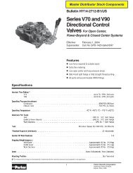
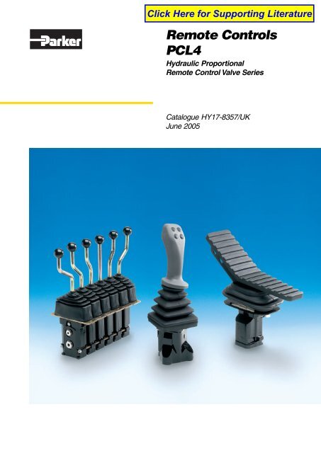
<strong>Remote</strong> <strong>Controls</strong><br />
<strong>PCL4</strong><br />
Hydraulic Proportional<br />
<strong>Remote</strong> Control Valve Series<br />
zrc01<br />
Catalogue HY17-8357/UK<br />
June 2005
Catalogue HY17-8357/UK<br />
Catalogue Information<br />
Catalogue layout<br />
This catalogue has been designed to give an overview of the<br />
<strong>PCL4</strong> series of valves and to make it easy for you to study and<br />
choose from the different valve functions available, so that we<br />
may customize your valve in accordance with your wishes.<br />
General information and technical data is given first, followed by<br />
descriptions of the various options that can be specified and,<br />
finally, by dimensional drawings for the respective valves.<br />
<strong>Remote</strong> <strong>Controls</strong> – Hydraulic<br />
<strong>PCL4</strong><br />
Each function is given as a subheading, e.g. Levers, followed<br />
by a brief description. This is followed by a series of<br />
alphanumeric codes, e.g. H1, H2, E4, together with a brief<br />
description of what each code represents.<br />
How to order your valve<br />
The next step is to complete our so-called “Customer<br />
Specification Form”, which enables detailed specification of the<br />
optional functions and port-specific control-pressure<br />
characteristics you wish to be incorporated into your valve.<br />
However, if you require only a simple, basic valve, in which all<br />
control-pressure ports have the same configuration, you can<br />
specify your valve by determining an ordering code in<br />
accordance with the information given on page 11. It is simply a<br />
matter of entering the codes for the desired options into the<br />
shaded boxes in the ordering code, as shown in the example.<br />
For assistance in configuring your valve, completing the<br />
Customer Specification Form or determining the ordering code,<br />
please do not hesitate to contact your nearest Parker<br />
representative, who will either help personally or refer you to the<br />
appropriate product specialist.<br />
The information in your Customer Specification Form will be<br />
entered into our computerized valve specification program,<br />
which generates a unique ID number that will be stamped into<br />
the data plate on your valve. (If you order your valve by means<br />
of an ordering code, the code will be stamped into the data<br />
plate on your valve.) Your valve specifications will then be stored<br />
on our database to facilitate accurate identification of the<br />
product in the event of re-ordering or service-related questions.<br />
Early consultation with Parker saves time and money<br />
Our experienced applications engineers have in-depth<br />
knowledge of different hydraulic systems and the ways in which<br />
they work. They are at your disposal to offer expert advice on<br />
the desired combination of functions, control characteristics and<br />
economic demands.<br />
By consulting Parker early in the project planning stage, you are<br />
assured of a comprehensive hydraulic system that gives your<br />
machine the best possible operating and control performance.<br />
Subject to alteration without prior notice. The diagrams in the<br />
catalogue show typical curves only. While the contents of the<br />
catalogue are updated continuously, the validity of the<br />
information given should always be confirmed. Technical<br />
information in the catalogue is applicable at an oil viscosity of<br />
30 mm 2 /s and temperature of 50 °C. For more detailed<br />
information, please contact Parker.<br />
Conversion factors<br />
1 kg = 2.2046 lb<br />
1 N = 0.22481 lbf<br />
1 bar = 14.504 psi<br />
1 l = 0.21997 UK gallon<br />
1 l = 0.26417 US gallon<br />
1 cm 3 = 0.061024 in 3<br />
1 m = 3.2808 feet<br />
1 mm = 0.03937 in<br />
9/5 °C + 32 = °F<br />
2 Parker Hannifin<br />
Mobile <strong>Controls</strong> Division<br />
Borås, Sweden
Catalogue HY17-8357/UK<br />
Index<br />
<strong>Remote</strong> <strong>Controls</strong> – Hydraulic<br />
<strong>PCL4</strong><br />
Contents<br />
Page<br />
Catalogue Information ................................................................................................... 2<br />
General Information ....................................................................................................... 4<br />
Ordering code ................................................................................................................ 5<br />
Technical data ................................................................................................................ 6<br />
Lever forces ................................................................................................................... 7<br />
Electrical data ................................................................................................................ 7<br />
Breaking capacity .......................................................................................................... 7<br />
Connections ................................................................................................................... 7<br />
Weight ............................................................................................................................ 7<br />
Valve type ...................................................................................................................... 8<br />
Control pressure ports ................................................................................................... 8<br />
Connections ................................................................................................................... 8<br />
Location of connections ................................................................................................ 8<br />
Control pressure ............................................................................................................ 8<br />
Mounting plate ............................................................................................................... 9<br />
Extra centring springs ................................................................................................... 9<br />
Levers E2, E3, E4 .......................................................................................................... 9<br />
Lever E1 ......................................................................................................................... 9<br />
Activating devices ........................................................................................................ 10<br />
Lever N2T .................................................................................................................... 10<br />
Lever N4T .................................................................................................................... 10<br />
Lever detents for <strong>PCL4</strong>02 ............................................................................................ 11<br />
Friction brake for <strong>PCL4</strong>02............................................................................................ 11<br />
Shuttle valve for signal on activation of valve ............................................................. 11<br />
<strong>PCL4</strong>01 levers ............................................................................................................. 12<br />
Dimensional drawings ........................................................................................... 12-17<br />
3 Parker Hannifin<br />
Mobile <strong>Controls</strong> Division<br />
Borås, Sweden
Catalogue HY17-8357/UK<br />
General Information<br />
<strong>Remote</strong> <strong>Controls</strong> – Hydraulic<br />
<strong>PCL4</strong><br />
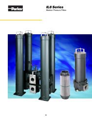
The <strong>PCL4</strong> is a stackable hydraulic<br />
control-pressure valve intended for the<br />
proportional, hydraulic remote control of<br />
directional valves, pumps with variable<br />
displacement, positioning cylinders, etc. It<br />
can be obtained with a co-ordinate lever<br />
(joystick), linear lever or foot pedal as the<br />
activating device.<br />
Freedom in machine design<br />
Good machine design is heavily<br />
dependent on the availability of versatile<br />
components and systems that can be<br />
combined in different ways to give<br />
optimum operating and control<br />
characteristics. Parker control systems<br />
give you the freedom to design your<br />
machines the way you want them, since<br />
they enable components such as<br />
directional valves and other control<br />
devices to be located ideally on the<br />
machine. This also gives advantages in<br />
production, since it greatly facilitates the<br />
building of machine sub-assemblies at<br />
different sites prior to collation for final<br />
assembly.<br />
Parker supplies a wide range of<br />
pneumatic, hydraulic and electric control<br />
devices that enable optimum ergonomic<br />
design of the machine-control station.<br />
(Please see separate brochures for<br />
information on our hydraulic and electric<br />
remote-control systems.)<br />
Safety<br />
The robust and simple construction of the<br />
<strong>PCL4</strong> remote control valve makes it very<br />
reliable and greatly facilitates training and<br />
servicing. This, together with consistently<br />
predictable control properties, gives a<br />
high level of operational safety for many<br />
years.<br />
Design<br />
The valve is made up of sections, each of<br />
which contains two 3-way pressure<br />
reducing valves (one per signal port). Up<br />
to 6 sections can be stacked into one and<br />
the same valve to give a total of 12 signal<br />
ports. Valves with four signal ports can be<br />
equipped with a coordinate lever<br />
(joystick). The cast-iron valve housing and<br />
reducer-valve spools of hardened,<br />
precision-ground steel ensure a long<br />
service life with minimal internal leakage.<br />
Special low-friction seals give effective<br />
protection against external leakage.<br />
The <strong>PCL4</strong> is designed to give minimal<br />
hysteresis and very good long-term<br />
control characteristics.<br />
Levers are of corrosion-resistant steel<br />
and can be fitted with plastic handles,<br />
balls or window knobs. Pedals can be of<br />
corrosion-resistant, pressed steel plate,<br />
aluminium or rubber-coated steel.<br />
Essential characteristics<br />
• Small dimensions enable simple,<br />
compact installation.<br />
• Robust, simple design gives great<br />
reliability and easy servicing.<br />
• Low, well-adapted lever forces and<br />
short lever strokes give good operating<br />
comfort.<br />
• Lever forces can be specified per<br />
control-pressure port to give functionspecific<br />
actuational resistance.<br />
• Low hysteresis gives consistent<br />
machine-function response to valve<br />
actuation.<br />
• Good metering properties enable<br />
gentle, proportional control.<br />
• Very wide range of control-pressure<br />
characteristics enables control of<br />
machine functions to be applicationoptimized.<br />
• Wide range of control devices and<br />
accessories gives great flexibility in<br />
system design.<br />
• Valve can be installed in arm rests of<br />
operator’s seat and fitted with sitesuited<br />
lever to give very ergonomic<br />
control station.<br />
• Quality materials and great precision<br />
in manufacturing, assembly and<br />
testing assure a quality product with<br />
low internal leakage and long service<br />
life.<br />
• Total compatibility with Parker<br />
directional valves gives predictable<br />
and harmonious system<br />
characteristics.<br />
4 Parker Hannifin<br />
Mobile <strong>Controls</strong> Division<br />
Borås, Sweden
Catalogue HY17-8357/UK<br />
Ordering Code<br />
<strong>Remote</strong> <strong>Controls</strong> – Hydraulic<br />
<strong>PCL4</strong><br />
<strong>PCL4</strong> — — — — —<br />
—<br />
Valve<br />
type<br />
Control<br />
pressure<br />
ports<br />
Thread<br />
connection<br />
Pump and<br />
tank<br />
connection<br />
Mounting<br />
plate<br />
Lever<br />
unit<br />
Lever<br />
type<br />
Characteristics<br />
Code<br />
Lever type<br />
Code<br />
Code<br />
Number of controlpressure<br />
ports<br />
Code<br />
S<br />
B<br />
Valve type<br />
01 For coordinate<br />
lever<br />
02 For linear lever(s)<br />
or pedal<br />
2<br />
4<br />
6<br />
8<br />
10<br />
12<br />
Thread connections<br />
G G1/4<br />
U 9/16-18 UNF-2B<br />
M M14x1.5<br />
Connection<br />
Pump and tank<br />
connections on<br />
side of valve<br />
Pump and tank<br />
connections on<br />
underside of valve<br />
Code<br />
H1<br />
H3<br />
HF<br />
E1<br />
E2<br />
E3<br />
E4<br />
N0<br />
N2<br />
N2T<br />
N4<br />
N4T<br />
F<br />
A36<br />
A95<br />
Lever unit<br />
Coordinate lever<br />
Straight linear lever<br />
Bent linear lever for<br />
increased spacing in case<br />
of several levers<br />
Linear or coordinate lever<br />
2-position thumb switch<br />
Linear or coordinate lever<br />
3-position toggle switch<br />
Linear or coordinate lever<br />
3-position toggle switch<br />
1 detent position<br />
Linear or coordinate lever<br />
3-position toggle switch<br />
2 detent positions<br />
Coordinate lever without<br />
thumb switch<br />
Coordinate lever with<br />
2 thumb switches<br />
Coordinate lever with<br />
3 thumb switches<br />
Coordinate lever with<br />
4 thumb switches<br />
Coordinate lever with<br />
5 thumb switches<br />
Pedal, pressed steel<br />
Pedal, cast aluminium<br />
Pedal, rubber coated steel<br />
plate<br />
Code<br />
M1<br />
M2<br />
M3<br />
M4<br />
M5<br />
M6<br />
A102<br />
Code<br />
S Straight*<br />
L Bent to the left*<br />
R Bent to the right*<br />
B Ball**<br />
W Window**<br />
* Type N levers only<br />
** Type H levers only<br />
Mounting plate<br />
Mounting plate for <strong>PCL4</strong>01<br />
Mounting plate for <strong>PCL4</strong>02 with<br />
four control-pressure ports<br />
Mounting plate for <strong>PCL4</strong>02<br />
Mounting plate for <strong>PCL4</strong>02 with<br />
two control-pressure ports<br />
Mounting plate for <strong>PCL4</strong>02<br />
Mounting plate for <strong>PCL4</strong>02<br />
Mounting plate for <strong>PCL4</strong>01,<br />
rectangular bellows (for <strong>PCL4</strong>01<br />
with N-type levers only)<br />
Characteristic<br />
No Breakaway Final Broken Overtr.<br />
pressure pressure stroke<br />
1 1.0 11.1<br />
2 2.0 5.4<br />
3 2.0 10.5<br />
4 5.0 15.6<br />
5 5.0 17.7<br />
6 5.0 20.9<br />
7 5.0 24.9<br />
8 5.5 15.6<br />
9 5.6 21.5<br />
10 6.0 27.2<br />
11 4.0 22.6 yes<br />
12 5.0 27.0 yes<br />
13 6.0 27.5 yes<br />
14 5.0 16.5 yes yes<br />
See pages 8 - 11 for more information about the different options available.<br />
How to order your valve<br />
The best way to order your valve is to fill in one of our “Customer<br />
Specification Forms”, in which you can specify all the optional<br />
functions you wish to be incorporated into your valve. However, if<br />
you need only a simple, basic valve, in which all control-pressure<br />
ports have the same configuration, you may use an ordering<br />
code similar to the one shown above. Simply select the desired<br />
options from the tables above and enter the appropriate codes<br />
into the boxes in the ordering code above.<br />
5 Parker Hannifin<br />
Mobile <strong>Controls</strong> Division<br />
Borås, Sweden
Catalogue HY17-8357/UK<br />
Technical Data<br />
<strong>Remote</strong> <strong>Controls</strong> – Hydraulic<br />
<strong>PCL4</strong><br />
Bellows<br />
Lever detent<br />
MD2<br />
Lever unit<br />
(activating<br />
device)<br />
Extra<br />
centring<br />
spring<br />
Mounting plate<br />
Tank<br />
connection<br />
Regulator<br />
Spool<br />
Pump<br />
connection<br />
Signal ports<br />
General<br />
The data given is applicable at an oil temperature of 50 °C<br />
(122 °F) and viscosity of 30 mm 2 /s (cSt) using mineral base oil<br />
according to DIN 51524.<br />
Pressures<br />
Supply pressure (pump pressure)<br />
Recommended supply pressure<br />
Control pressure<br />
Breakaway pressure<br />
Return-line pressure<br />
Flow rate<br />
Control flow<br />
Hysteresis<br />
Hysteresis<br />
max. 100 bar (1450 psi)<br />
15 bar (218 psi)<br />
higher than max.<br />
control pressure<br />
max. 75 bar 1090 psi)<br />
min. 1 bar, (14,5 psi)<br />
max. 16 bar (232 psi)<br />
max. 3 bar (44 psi)<br />
max. 15 l/min (4 USgpm)<br />
max. 0.5 bar (7,3 psi)<br />
Hydraulic fluids<br />
Best performance is obtained using mineral-base oil of high<br />
quality and cleanness in the hydraulic system.<br />
HLP hydraulic fluids (DIN 51524), automatic-gearbox oil<br />
type A and API CD engine oils can be used.<br />
Viscosity range<br />
10-380 mm 2 /s (cSt)<br />
Performance efficency will be reduced if outside the ideal<br />
values. These extreme conditions must be evaluated by the user<br />
to establish suitability of the products performance.<br />
Filtration<br />
Filtration should be arranged so that the Target Contamination<br />
Class 18/16/13 according to ISO 4406 is not exceeded.<br />
Technical information in this catalogue is applicable at an<br />
oil viscosity of 30 mm 2 /s and temperature of 50 °C using<br />
nitrile rubber seals.<br />
Temperature<br />
Min. ambient temperature<br />
Max. ambient temperature<br />
Min. oil temperature<br />
Max. oil temperature<br />
Temperature change<br />
–40 °C (-40 °F)<br />
+60 °C (140 °F)<br />
–20 °C (-4 °F)<br />
+70 °C (166 °F)<br />
max. 100 °C/s.<br />
max. 212 °F/s<br />
Product operating limits are broadly within the above range, but<br />
satisfactory operation within the specification may not be<br />
accomplished. Leakage and response will be affected when<br />
used at temperature extremes and it is up to the user to<br />
determine acceptability at these levels.<br />
Leakage<br />
From pump connection to tank<br />
connection with the spool in<br />
neutral position and a supply<br />
pressure of 40 bar (580 psi)<br />
max. 20 cm 3 /min<br />
(1.22 in 3 )per<br />
control-pressure port<br />
Warning<br />
If the filtration demands are not met, the valve poppets<br />
can jam in the open position, with the result that the valve<br />
remains actuated. It is not possible to force back jammed<br />
poppets mechanically.<br />
6 Parker Hannifin<br />
Mobile <strong>Controls</strong> Division<br />
Borås, Sweden
Catalogue HY17-8357/UK<br />
Technical Information<br />
<strong>Remote</strong> <strong>Controls</strong> – Hydraulic<br />
<strong>PCL4</strong><br />
Lever forces<br />
All lever forces stated are applicable at a control pressure of 15<br />
bar (valve not fitted with an extra centring spring). Pedal forces<br />
are applicable when the C2 centring spring is used<br />
(see page 9).<br />
Normal force for linear lever, fully actuated 1.2 Nm<br />
Normal force for coordinate lever (joystick)<br />
one function fully actuated<br />
1.8 Nm<br />
two functions fully actuated<br />
2.4 Nm<br />
Normal force for pedal, fully actuated<br />
5.7 Nm<br />
Electrical data<br />
(applies to switch in E- and N-type levers)<br />
The data given below is what is needed to obtain the maximum<br />
service life. The values can be exceeded with retained function,<br />
but will result in a reduction in service life.<br />
In the event of inductive loading, a protective diode must be<br />
fitted.<br />
Breaking capacity<br />
DC, resistive loading<br />
2A/24V<br />
DC or AC, inductive loading<br />
1A/24V<br />
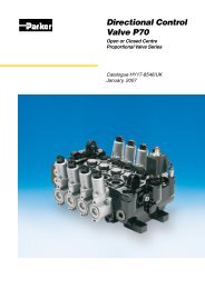
Circuit diagram showing two-section <strong>PCL4</strong> with two linear levers<br />
controlling one hydraulic directional valve containing two spool<br />
sections.<br />
Connections<br />
Three different types of connection thread are available:<br />
G1/4 for flat seal (type Tredo) according to ISO 228/1 (G version)<br />
9/16-18 UNF-2B (for O-ring) according to SAE J1926/1 (U version)<br />
M14 x 1.5 (metric ISO thread) for flat seal (M version)<br />
Weight<br />
The weight of the unit varies with its configuration. A few<br />
examples are given below.<br />
Valve with linear lever<br />
approx. 1.6 kg/section<br />
Valve with coordinate lever approx. 3.2 kg<br />
Valve with pedal (F)<br />
approx. 3.0 kg<br />
Circuit diagram showing two-section <strong>PCL4</strong> with one coordinate<br />
lever (joystick) controlling one hydraulic directional valve<br />
containing two spool sections.<br />
7 Parker Hannifin<br />
Mobile <strong>Controls</strong> Division<br />
Borås, Sweden
Catalogue HY17-8357/UK<br />
Technical Information<br />
<strong>Remote</strong> <strong>Controls</strong> – Hydraulic<br />
<strong>PCL4</strong><br />
Every valve is customized. The following options are used to configure a valve.<br />
Valve type<br />
<strong>PCL4</strong>01 Valve with coordinate lever (joystick)<br />
Control pressure in bar<br />
25<br />
<strong>PCL4</strong>02 Valve with linear lever(s) or pedal<br />
Control pressure ports<br />
2-12 4 in <strong>PCL4</strong>01<br />
2, 4, 6, 8, 10 or 12 in <strong>PCL4</strong>02<br />
Connections<br />
20<br />
15<br />
10<br />
Final pressure<br />
G Connections with G1/4 thread<br />
U Connections with 9/16-18 UNF-2B thread<br />
5<br />
Breakaway pressure<br />
M Connections with M14 x 1.5 thread<br />
0<br />
Location of connections<br />
0 20 40 60 80 100<br />
Lever stroke in %<br />
All control-pressure ports are located on the underside of the<br />
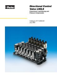
Diagram shows an example of a straight characteristic.<br />
valve. The pump and tank connections can be located on the<br />
underside or side of the valve. See dimensional drawings. Control pressure in bar<br />
S Pump and tank connections fitted on the side of the<br />
valve.<br />
25<br />
B Pump and tank connections fitted on the underside of<br />
the valve.<br />
20<br />
Full supply pressure<br />
Control pressure<br />
Control pressure characteristics can be obtained in an almost<br />
infinite number of versions. They are classified into four different<br />
groups.<br />
• Straight characteristic<br />
• Straight characteristic with overtravel stroke<br />
• Broken characteristic<br />
• Broken characteristic with overtravel stroke<br />
With the straight characteristic, the control pressure changes<br />
proportionally with the lever stroke. With the broken<br />
characteristic, the control pressure changes proportionally with<br />
the lever stroke up to a pre-determined breakpoint, after which<br />
the characteristic continues to change proportionally, but with a<br />
steeper characteristic. This is useful when there is a big<br />
difference between breakout pressure and final pressure and a<br />
need to fine-regulate the beginning of the stroke.<br />
With the overtravel stroke, the control pressure becomes<br />
equal to the supply pressure. This is recommended primarily for<br />
directional valves that have a free flow gallery (CFO). The<br />
overtravel stroke serves to ensure full actuation regardless of<br />
any return-spring tolerances in the spool actuator of the<br />
directional valve.<br />
To calculate a suitable control-pressure characteristic, the<br />
following information is needed:<br />
Breakout pressure:<br />
The pressure at which the valve just begins to open.<br />
Selectable between 1 and 16 bar.<br />
Final pressure:<br />
Max. control pressure (fully actuated activating device)<br />
or, in case of overtravel stroke, the pressure level<br />
obtained on reaching the overtravel stroke. Selectable<br />
between 5.5 and 75 bar.<br />
Breakpoint:<br />
The lever stroke and pressure at which the broken<br />
characteristic changes characteristic.<br />
Overtravel stroke:<br />
The part of the activating-device stroke that constitutes<br />
overtravel.<br />
For assistance in calculating the most suitable control-pressure<br />
characteristic, please contact your nearest Parker representative.<br />
15<br />
10<br />
5<br />
0<br />
0 20 40 60 80 100<br />
Lever stroke in %<br />
Diagram shows an example of a straight characteristic with<br />
overtravel stroke that gives full supply pressure.<br />
Control pressure in bar<br />
25<br />
20<br />
15<br />
10<br />
5<br />
0<br />
0 20 40 60 80 100<br />
Lever stroke in %<br />
Diagram shows an example of a broken characteristic.<br />
Control pressure in bar<br />
25<br />
20<br />
15<br />
10<br />
5<br />
Final pressure<br />
Breakaway pressure<br />
Final pressure<br />
Breakpoint<br />
Breakaway pressure<br />
Full supply pressure<br />
Final pressure<br />
Breakpoint<br />
Breakaway pressure<br />
0<br />
0 20 40 60 80 100<br />
Lever stroke in %<br />
Diagram shows an example of a broken characteristic with<br />
overtravel stroke that gives full supply pressure.<br />
8 Parker Hannifin<br />
Mobile <strong>Controls</strong> Division<br />
Borås, Sweden
Catalogue HY17-8357/UK<br />
Technical Information<br />
<strong>Remote</strong> <strong>Controls</strong> – Hydraulic<br />
<strong>PCL4</strong><br />
Mounting plate<br />
A number of different mounting plates for fitting the valve to the<br />
machine are available (see dimensional drawings).<br />
M1 Mounting plate for <strong>PCL4</strong>01<br />
M2 Mounting plate for <strong>PCL4</strong>02 with four control pressure<br />
ports<br />
M3 Mounting plate for <strong>PCL4</strong>02<br />
M3S Same as M3 but in Stainless steel<br />
M4 Mounting plate for <strong>PCL4</strong>02 with two control pressure<br />
ports<br />
M5 Mounting plate for <strong>PCL4</strong>02<br />
M6 Mounting plate for <strong>PCL4</strong>02<br />
A102 Mounting plate for <strong>PCL4</strong>01, rectangular bellows<br />
(for <strong>PCL4</strong>01 with type N levers only)<br />
Extra centring spring<br />
Lever E1<br />
Thumb switch<br />
Extra centring springs<br />
Any control-pressure port can be fitted with an extra centring<br />
spring, which serves primarily to ensure centralization of the<br />
lever unit. (Heavier lever units need stronger centring springs.)<br />
Also, by fitting different springs at different ports, a coordinate<br />
lever (for instance) can be given different actuational<br />
resistances for different functions. A list of the different springs<br />
available is given in the table below, together with their<br />
respective force increases on the push rod. These force values<br />
should not be confused with the inherent lever forces, since the<br />
various activating devices have different ratios.<br />
F1 is the force transmission on the activating device when the<br />
spool is in the neutral position.<br />
F2 is the force transmission on a fully actuated activating<br />
device.<br />
F1<br />
F2<br />
C7 5 N 8 N<br />
C0 19 N 33 N<br />
C1 25 N 45 N<br />
C5 35 N 71 N<br />
C2 49 N 71 N<br />
C3 51 N 92 N<br />
C4 65 N 169 N<br />
C6 100 N 214 N<br />
C8 130 N 243 N<br />
Breaker symbol<br />
Red cable<br />
Levers E2, E3, E4<br />
Grey cable<br />
Black cable<br />
Thumb switch<br />
(toggle type)<br />
The detent position<br />
on lever E3 results in<br />
a connection between<br />
the red and black<br />
cables.<br />
Breaker symbol<br />
Black cable<br />
Red cable<br />
Grey cable<br />
9 Parker Hannifin<br />
Mobile <strong>Controls</strong> Division<br />
Borås, Sweden
Catalogue HY17-8357/UK<br />
Technical Information<br />
Activating devices<br />
Several different types of activating device are available:<br />
• Straight lever with ball<br />
• Straight lever with window knob for insertion of functional<br />
symbol<br />
• Straight lever with thicker plastic handle<br />
(can be equipped with different switches)<br />
• Ergonomic multi-function lever that can be equipped<br />
with up to 5 thumb-switches<br />
• Pedal<br />
See also dimensional drawings.<br />
H1<br />
H3<br />
H3S<br />
H4-H7<br />
E0<br />
E1<br />
E2<br />
E3<br />
E4<br />
N0<br />
N2<br />
N2T<br />
N4<br />
N4T<br />
F<br />
A36<br />
A95<br />
Coordinate lever (joystick) with ball or window knob<br />
Straight linear lever with ball or window knob<br />
Lever H3 in stainless steel<br />
Bent linear lever with ball or window knob<br />
Linear or coordinate lever without thumb switch<br />
Linear or coordinate lever with 2-position thumb switch<br />
Linear or coordinate lever with 3-position, springcentred<br />
toggle switch<br />
Linear or coordinate lever with 3-position toggle switch<br />
with detent at one end position<br />
Linear or coordinate lever with 3-position toggle switch<br />
with detents at both end positions<br />
Coordinate lever without thumb switch<br />
Coordinate lever with 2 instantaneous switches<br />
(Nos. 1 and 2)<br />
Coordinate lever with 3 instantaneous switches<br />
(Nos. 1, 2 and 5)<br />
Coordinate lever with 4 instantaneous switches<br />
(Nos. 1-4)<br />
Coordinate lever with 5 instantaneous switches<br />
(Nos. 1-5)<br />
Pedal of pressed steel plate<br />
Pedal of cast aluminium<br />
Pedal of rubber coated steel<br />
<strong>Remote</strong> <strong>Controls</strong> – Hydraulic<br />
<strong>PCL4</strong><br />
Lever N2T<br />
right-hand<br />
version<br />
Right-hand version of lever, i.e. intended for mounting in righthand<br />
arm rest.<br />
Lever N4T<br />
left-hand version<br />
Push buttons<br />
1 2<br />
3 4 5<br />
Left-hand version of lever, i.e. intended for mounting in left-hand<br />
arm rest.<br />
Breaker symbol (colours of output cables)<br />
Push button<br />
1 2 3 4 5<br />
White Green Brown Pink Grey Green/<br />
yellow<br />
10 Parker Hannifin<br />
Mobile <strong>Controls</strong> Division<br />
Borås, Sweden
Catalogue HY17-8357/UK<br />
Technical Information<br />
Lever detents for <strong>PCL4</strong>02<br />
Linear levers can be equipped with a detent that locks the lever<br />
in the fully actuated position (for one or both control-pressure<br />
ports).<br />
MD2 Mechanical end-position detent. Released by pulling<br />
the lever out of its detented position. It can be used<br />
with signal pressures of up to 30 bar inclusive.<br />
See figure on page 6.<br />
ED2 Electric end-position detent. A solenoid locks the lever<br />
in its fully actuated position. By means of a force index,<br />
a greater resistance to lever actuation is felt by the<br />
operator just before the lever enters the detented<br />
position, i.e. after approx. 75% of the lever stroke. The<br />
lever is released from the detented position by<br />
breaking the current to the solenoid. In emergencies,<br />
the lever can be pulled out of the detented position<br />
manually. Since sections equipped with the ED2 do not<br />
have protective bellows, it is important that they are<br />
installed in the machine in such a way as to prevent the<br />
ingress of dirt (which would impair the function of the<br />
valve).<br />
At a signal pressure of 35 bar, the holding force is<br />
min. 19 N.<br />
Electrical data:<br />
Solenoid voltage: 24 VDC max. 3.2 W 100% ED<br />
<strong>Remote</strong> <strong>Controls</strong> – Hydraulic<br />
<strong>PCL4</strong><br />
ED2 - electric end-position detent.<br />
Index that gives<br />
increased<br />
resistance to lever<br />
actuation just<br />
before the solenoid<br />
locks the lever into<br />
the detented<br />
position.<br />
Electric holding<br />
solenoid<br />
Index that indicates<br />
when lever is in<br />
neutral<br />
Brake unit<br />
Friction brake for <strong>PCL4</strong>02<br />
S2 Friction brake with centre-position indication.<br />
Movement is braked so that the lever remains in any<br />
position in which it is put. The centre position is indexmarked<br />
for reliable positioning into neutral. Due to the<br />
size of friction brake, a 35 mm spacer block is fitted<br />
between the sections in valves containing more than<br />
one section.<br />
See dimensional drawing.<br />
S2 - friction brake with centre-position indication.<br />
Shuttle valve for signal on activation of valve<br />
A42 <strong>PCL4</strong>02 with 2 control-pressure ports, and with the<br />
pump and tank connections on the underside of the<br />
valve, can be equipped with a shuttle valve that emits a<br />
signal as soon as the valve is activated.<br />
A S B<br />
Signal obtained in port S on activation of valve.<br />
11 Parker Hannifin<br />
Mobile <strong>Controls</strong> Division<br />
Borås, Sweden
Catalogue HY17-8357/UK<br />
Dimensional Drawings<br />
<strong>Remote</strong> <strong>Controls</strong> – Hydraulic<br />
<strong>PCL4</strong><br />
<strong>PCL4</strong>01 levers<br />
75 (2.95)<br />
18˚ a) 25˚ b)<br />
∅38 (∅1.50)<br />
18˚ a) 25˚ b)<br />
70 (2.76)<br />
18˚ a) 25˚ b)<br />
(∅1.57) ∅40 d)<br />
18˚ a) 25˚ b)<br />
(inch)<br />
(8.27)<br />
210<br />
200 c)<br />
(0.87)<br />
(0.87)<br />
(7.87)<br />
22<br />
22<br />
Lever E0 - E4<br />
a) Applies to max. actuation of one function<br />
b) Applies to max. actuation of two functions<br />
c) 210 with window knob<br />
d) Ø27 with window knob<br />
Lever H1 with ball<br />
85 (3.75)<br />
115 (4.53) 56 (2.20)<br />
55 (2.17)<br />
(9.25)<br />
235<br />
235<br />
220<br />
(0.87)<br />
(0.87)<br />
(9.25)<br />
(8.66)<br />
22<br />
22<br />
18˚ a)<br />
25˚ b)<br />
18˚ a)<br />
25˚ b)<br />
18˚ a)<br />
25˚ b)<br />
18˚ a)<br />
25˚ b)<br />
Lever N0 - N4T<br />
Straight version<br />
Lever N0 - N4T<br />
Right-hand version and A102 mounting plate<br />
12 Parker Hannifin<br />
Mobile <strong>Controls</strong> Division<br />
Borås, Sweden
Catalogue HY17-8357/UK<br />
Dimensional Drawings<br />
<strong>PCL4</strong>01 valve housing<br />
<strong>PCL4</strong>01 with all connections in the underside of the valve and<br />
with A102 mounting plate.<br />
<strong>Remote</strong> <strong>Controls</strong> – Hydraulic<br />
<strong>PCL4</strong><br />
<strong>PCL4</strong>01 with tank and pump connections on the side of the<br />
valve and with M1 mounting plate.<br />
(inch)<br />
Controlpressure<br />
port 3<br />
108 (4.25)<br />
54 (2.13)<br />
40 (1.57)<br />
∅125 (∅4.92)<br />
∅100 (∅3.94)<br />
30 (1.18)<br />
15 (0.59)<br />
15 (0.59)<br />
Mounting screws out of<br />
sight (under bellows)<br />
15<br />
(0.59)<br />
10<br />
(0.39)<br />
Control-pressure<br />
port 2<br />
66<br />
(2.60)<br />
7<br />
(0.28)<br />
(0.59)<br />
15 15<br />
(0.59)<br />
40<br />
(1.57)<br />
54<br />
(2.135)<br />
108<br />
(4.25)<br />
7 (0.28)<br />
15<br />
(0.59)<br />
30 20<br />
(1.18)<br />
(0.79)<br />
95<br />
(3.74)<br />
Control-pressure<br />
port 4<br />
Pump<br />
connection<br />
Tank<br />
connection<br />
Control-pressure port 1<br />
70 (2.76)<br />
Mounting hole, min. Ø85 mm<br />
(3.35 inch) Mounting hole, min Ø90 mm (3.54inch)<br />
(4.25)<br />
(0.16)<br />
4<br />
96 (3.78)<br />
Tank<br />
connection<br />
Pump<br />
connection<br />
31 (1.22) 32 (1.26) 4 (0.16)<br />
96 (3.78)<br />
13 Parker Hannifin<br />
Mobile <strong>Controls</strong> Division<br />
Borås, Sweden
Catalogue HY17-8357/UK<br />
Dimensional Drawings<br />
<strong>Remote</strong> <strong>Controls</strong> – Hydraulic<br />
<strong>PCL4</strong><br />
<strong>PCL4</strong>02 Levers with ball<br />
Lever H5<br />
Lever H4<br />
mounting position 4<br />
Lever H3<br />
Lever H4<br />
mounting position 2<br />
Lever H5<br />
Lever H6<br />
∅25 (0.98)<br />
50 (1.97) 50 (1.97) 50 (1.97) 50 (1.97) 50 (1.97)<br />
15 (0.59) 30 (1.18) 45 (1.77)<br />
(inch)<br />
190 (7.48)<br />
<strong>PCL4</strong>02 with S2 friction brake on two sections<br />
<strong>PCL4</strong>02 with H3 lever and window knob<br />
83 (3.27)<br />
25°<br />
25°<br />
∅27(Ø1.06)<br />
200<br />
(7.87)<br />
(1.02)<br />
26<br />
70 (2.76)<br />
Spacer block<br />
Sections with S2<br />
14 Parker Hannifin<br />
Mobile <strong>Controls</strong> Division<br />
Borås, Sweden
Catalogue HY17-8357/UK<br />
Dimensional Drawings<br />
<strong>PCL4</strong>02 Housing and mounting plates<br />
Valve housing with bottom<br />
connection of pump and tank<br />
<strong>Remote</strong> <strong>Controls</strong> – Hydraulic<br />
<strong>PCL4</strong><br />
M3 mounting plate<br />
Valve housing with side<br />
connection of pump and tank<br />
(inch)<br />
Tank connection<br />
53 (2.59)<br />
(0.43)<br />
1 (0.04)<br />
28,5<br />
(1.12)<br />
11<br />
Pump connection<br />
24,5 4 (0.16)<br />
17,5 35 ∅7<br />
(0.96)<br />
(0.69) (1.38) (Ø0.28)<br />
(4.92)<br />
125<br />
41 30 41<br />
(1.61) (1.18) (1.61)<br />
(1.10)<br />
28<br />
(3.39)<br />
86<br />
Control<br />
pressure<br />
port B<br />
Control<br />
pressure<br />
port A<br />
Ø6.5 mm (0.26 inch) hole<br />
for cable passage<br />
Section 1 Section 6 * Applies to M2, M3, M4 and M6<br />
4* (0.16)<br />
80 (3.15)<br />
63 (2.48)<br />
96 (3.78)<br />
31 32<br />
(1.22) (1.26)<br />
Tank<br />
connection<br />
Pump<br />
connection<br />
40 (1.57) 20<br />
(0.79)<br />
L<br />
Number of sections L mm L inch<br />
1 35 1.38<br />
2 70 2.76<br />
3 105 4.13<br />
4 140 5.51<br />
5 175 6.89<br />
6 210 8.27<br />
(Ø4.92)<br />
(3.94)<br />
(3.39)<br />
∅125<br />
100<br />
86<br />
M2 mounting plate M4 mounting plate M6 mounting plate<br />
100 (3.94)<br />
70 (2.76)<br />
35(1.38)<br />
Ø6.5 mm (0.26 inch)<br />
hole for cable passage<br />
Mounting hole, min<br />
Ø92 mm (3.62 inch)<br />
(0.28)<br />
7<br />
(0.59)<br />
15<br />
(1.69)<br />
(1.97)<br />
43<br />
50<br />
∅7<br />
(Ø0.28)<br />
(4.92)<br />
(4.33)<br />
(3.39)<br />
125<br />
110<br />
86<br />
55 (2.17)<br />
40 (1.57)<br />
Ø6.5 mm (0.26 inch)<br />
hole for cable passage<br />
(1.10)<br />
28<br />
(1.57)<br />
(1.87)<br />
∅7<br />
(Ø0.28)<br />
(4.92)<br />
(4.33)<br />
(3.39)<br />
125<br />
110<br />
86<br />
69(2.72)<br />
55(2.17)<br />
Ø6.5 mm (0.26 inch)<br />
hole for cable passage<br />
(1.10)<br />
28<br />
(1.57)<br />
(1.87)<br />
40<br />
47,5<br />
40<br />
47,5<br />
15<br />
17,5<br />
50 (1.97)<br />
(0.59)<br />
(0.69)<br />
22,5<br />
30<br />
2,5 (0.10)<br />
(0.89)<br />
(1.18)<br />
27,5<br />
35<br />
2(0.08)<br />
(1.08)<br />
(1.38)<br />
15 Parker Hannifin<br />
Mobile <strong>Controls</strong> Division<br />
Borås, Sweden
Catalogue HY17-8357/UK<br />
Dimensional Drawings<br />
<strong>Remote</strong> <strong>Controls</strong> – Hydraulic<br />
<strong>PCL4</strong><br />
<strong>PCL4</strong>02 Pedal F and M5 mounting plate<br />
For housing dimensions, see page 15<br />
90 (3.54) 90 (3.54)<br />
80 (3.15) 80 (3.15) ∅9 (∅0.35)<br />
mounting hole<br />
(inch)<br />
32 (1.26)<br />
32 (1.26)<br />
20 (0.79)<br />
20 (0.79)<br />
71 (2.80)<br />
130 (5.12) 130 (5.12)<br />
11˚<br />
23<br />
72 (2.83)<br />
52 (2.05)<br />
30 (1.18)<br />
24<br />
(091)<br />
(0.94)<br />
11˚<br />
4<br />
(0.16)<br />
M5 mounting plate<br />
<strong>PCL4</strong>02 Pedal A36<br />
11˚<br />
(0.91)<br />
Port A<br />
Port B<br />
155˚<br />
(1.14)<br />
(1.24)<br />
29<br />
31,5<br />
74 (2.91)<br />
56 (2.20)<br />
24 23<br />
11˚<br />
(0.94)<br />
30<br />
(1.18)<br />
102 (4.02)<br />
Port A<br />
Port B<br />
81 (3.19)<br />
56 (2.20)<br />
71 (2.80) 44,5 (1.75)<br />
M16-6H*<br />
130 (5.12)<br />
* Bracket for lever attachment<br />
(if required)<br />
290 (11.42)<br />
16 Parker Hannifin<br />
Mobile <strong>Controls</strong> Division<br />
Borås, Sweden
Catalogue HY17-8357/UK<br />
Dimensional Drawings<br />
<strong>Remote</strong> <strong>Controls</strong> – Hydraulic<br />
<strong>PCL4</strong><br />
<strong>PCL4</strong>02 Pedal A95<br />
For housing dimensions, see page 15<br />
(inch)<br />
(290) [11.42]<br />
160 (6.30)<br />
3 (0.12)<br />
110 (4.33)<br />
110 (4.33)<br />
55 (2.17)<br />
3 19,5<br />
(0.77)<br />
39 (1.54)<br />
(0.12)<br />
37 (1.46)<br />
41 (1.61)<br />
55 (2.17)<br />
82 (3.23)<br />
55 (2.17)<br />
150 (5.91)<br />
80 (3.15)<br />
M10x22 screw for mounting<br />
of valve in cab<br />
140 (5.51)<br />
112 (4.41)<br />
163 (6.42)<br />
11˚<br />
11˚<br />
49 (1.93)<br />
22 (0.87)<br />
98˚<br />
52˚<br />
10<br />
(0.39)<br />
12<br />
30<br />
(1.18)<br />
(0.47)<br />
(∅0.39)<br />
∅10<br />
150 (5.91)<br />
Lever fitted here<br />
(if required)<br />
6 (0.24)<br />
50 (1.97)<br />
30 (1.18)<br />
15 (0.59)<br />
4<br />
Bellows<br />
(0.16)<br />
∅10 (∅0.39)<br />
R15 (R0.59)<br />
Gas damper fitted here<br />
(if required)<br />
Space intended for floor mat,<br />
thickness 12-15 mm<br />
Port B<br />
9 (0.39)<br />
9 (0.35)<br />
Port A<br />
113 (4.45)<br />
17 Parker Hannifin<br />
Mobile <strong>Controls</strong> Division<br />
Borås, Sweden
Catalogue HY17-8357/UK<br />
Notes<br />
<strong>Remote</strong> <strong>Controls</strong> – Hydraulic<br />
<strong>PCL4</strong><br />
18 Parker Hannifin<br />
Mobile <strong>Controls</strong> Division<br />
Borås, Sweden
!<br />
WARNING<br />
FAILURE OR IMPROPER SELECTION OR IMPROPER USE OF THE PRODUCTS AND/OR SYSTEMS DESCRIBED<br />
HEREIN OR RELATED ITEMS CAN CAUSE DEATH, PERSONAL INJURY AND PROPERTY DAMAGE.<br />
This document and other information from Parker Hannifin Corporation, its subsidiaries and authorized distributors provide<br />
product and/or system options for further investigation by users having technical expertise. It is important that you analyze all<br />
aspects of your application, including consequences of any failure, and review the information concerning the product or<br />
system in the current product catalogue. Due to the variety of operating conditions and applications for these products or<br />
systems, the user, through its own analysis and testing, is solely responsible for making the final selection of the products and<br />
systems and assuring that all performance, safety and warning requirements of the application are met.<br />
The products described herein, including without limitation, product features, specifications, designs, availability and pricing, are<br />
subject to change by Parker Hannifin Corporation and its subsidiaries at any time without notice.<br />
Offer of Sale<br />
Please contact your Parker representation for a detailed ”Offer of Sale”.
Hydraulics Group<br />
Sales Offices<br />
Europe<br />
Austria<br />
Wiener Neustadt<br />
Tel: +43 (0)2622 23501<br />
Fax: +43 (0)2622 66212<br />
Belgium<br />
Nivelles<br />
Tel: +32 (0)67 280 900<br />
Fax: +32 (0)67 280 999<br />
Czech Republic<br />
Klecany<br />
Tel: +420 284 083 111<br />
Fax: +420 284 083 112<br />
Denmark<br />
Ballerup<br />
Tel: +45 4356 0400<br />
Fax: +45 4373 8431<br />
Finland<br />
Vantaa<br />
Tel: +358 (0)9 4767 31<br />
Fax: +358 (0)9 4767 3200<br />
France<br />
Contamine-sur-Arve<br />
Tel: +33 (0)450 25 80 25<br />
Fax: +33 (0)450 03 67 37<br />
Germany<br />
Kaarst<br />
Tel: +49 (0)2131 4016 0<br />
Fax: +49 (0)2131 4016 9199<br />
Hungary<br />
Budapest<br />
Tel: +36 (06)1 220 4155<br />
Fax: +36 (06)1 422 1525<br />
Ireland<br />
Dublin<br />
Tel: +353 (0)1 293 9999<br />
Fax: +353 (0)1 293 9900<br />
Italy<br />
Corsico (MI)<br />
Tel: +39 02 45 19 21<br />
Fax: +39 02 4 47 93 40<br />
The Netherlands<br />
Oldenzaal<br />
Tel: +31 (0)541 585000<br />
Fax: +31 (0)541 585459<br />
Norway<br />
Ski<br />
Tel: +47 64 91 10 00<br />
Fax: +47 64 91 10 90<br />
Poland<br />
Warsaw<br />
Tel: +48 (0)22 863 49 42<br />
Fax: +48 (0)22 863 49 44<br />
Portugal<br />
Leca da Palmeira<br />
Tel: +351 22 9997 360<br />
Fax: +351 22 9961 527<br />
Slovakia<br />
Ref. Czech Republic<br />
Spain<br />
Madrid<br />
Tel: +34 91 675 73 00<br />
Fax: +34 91 675 77 11<br />
Sweden<br />
Spånga<br />
Tel: +46 (0)8 597 950 00<br />
Fax: +46 (0)8 597 951 10<br />
Turkey<br />
Merter/Istanbul<br />
Tel.: +90 212 482 91 06 or 07<br />
Fax: +90 212 482 91 10<br />
United Kingdom<br />
Warwick<br />
Tel: +44 (0)1926 317 878<br />
Fax: +44 (0)1926 317 855<br />
International<br />
Australia<br />
Castle Hill<br />
Tel: +61 (0)2-9634 7777<br />
Fax: +61 (0)2-9899 6184<br />
Canada<br />
Milton, Ontario<br />
Tel: +1 905-693-3000<br />
Fax: +1 905-876-0788<br />
China<br />
Beijing<br />
Tel: +86 10 6561 0520<br />
Fax: +86 10 6561 0526<br />
Asia Pacific Group<br />
Hong Kong, Kowloon<br />
Tel: +852 2428 8008<br />
Fax: +852 2425 6896<br />
India<br />
Mumbai<br />
Tel: +91 22 7907081<br />
Fax: +91 22 7907080<br />
Japan<br />
Tokyo<br />
Tel: +(81) 3 6408 3900<br />
Fax: +(81) 3 5449 7201<br />
Latin America Group<br />
Brazil<br />
Tel: +55 12 3954-5100<br />
Fax: +55 12 3954-5266<br />
South Africa<br />
Kempton Park<br />
Tel: +27 (0)11-961 0700<br />
Fax: +27 (0)11-392 7213<br />
USA<br />
Cleveland (industrial)<br />
Tel: +1 216-896-3000<br />
Fax: +1 216-896-4031<br />
Lincolnshire (mobile)<br />
Tel: +1 847-821-1500<br />
Fax: +1 847-821-7600<br />
Parker Hannifin is the world’s premier supplier of motion and control systems<br />
and solutions, with sales and manufacturing facilities throughout the world. For<br />
product information and details of your nearest Parker sales office, visit us at<br />
www.parker.com or call free on 00800 2727 5374.<br />
Catalogue HY17-8357/UK<br />
PDF 06/05<br />
© Copyright 2005<br />
Parker Hannifin Corporation<br />
All rights reserved.