Directional Control Valve P70 - Oleosistemas
Directional Control Valve P70 - Oleosistemas
Directional Control Valve P70 - Oleosistemas

Create successful ePaper yourself
Turn your PDF publications into a flip-book with our unique Google optimized e-Paper software.
Catalogue HY17-8546/UK<br />
System description<br />
<strong>Directional</strong> <strong>Control</strong> <strong>Valve</strong>s<br />
<strong>P70</strong><br />
B<br />
A<br />
PF<br />
PS<br />
P2<br />
T4<br />
P1<br />
UL<br />
T2B<br />
T3<br />
TPB<br />
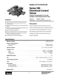
Principle circuit diagram for valve with load sensing<br />
Load sensing systems, LS<br />
(<strong>Valve</strong> with load sensing, <strong>P70</strong>LS)<br />
In the load sensing system both pressure and flow are modulated<br />
to match immediate needs from the consumers, with a pressure<br />
level corresponding to the heaviest load at that moment.<br />
When supplied from a variable displacement pump the<br />
directional control valve sends a load signal to the pump control<br />
regulator, which adjusts the pump output to maintain a constant<br />
pressure difference between the pump output and the load<br />
signal.<br />
In the <strong>P70</strong>LS, the free flow gallery is used to collect the load<br />
pressures from all the motor ports of the valve. The signal of the<br />
highest load is then delivered to the variable pump regulator.<br />
In order to achieve good operating characteristics, the pump<br />
should be sized to deliver flow equal to the sum of all simultaneously<br />
working functions. If the control pressure difference cannot<br />
be maintained, the operating characteristics of the valve can<br />
quickly deteriorate, and the controlled functions will influence<br />
each other, progressively resulting in lower loads receiving more<br />
flow than the higher ones.<br />
In common with a constant flow system, simultaneously<br />
working functions should have approximately the same pressure<br />
requirement or they should be divided into separate circuits for<br />
high operating efficiency.<br />
q(l/min)<br />
80<br />
60<br />
40<br />
20<br />
0<br />
0<br />
Flow rate in work port<br />
lift<br />
250 bar lower<br />
50 bar<br />
20 40 60 80 100<br />
Lever stroke in %<br />
q pump<br />
In the <strong>P70</strong>LS equipped with PC, ECS and ECH closed spoolactuators,<br />
the spools are pressure compensated, with the result<br />
that the load’s influence on speed is negligible.<br />
Operating characteristics<br />
With a correctly adjusted <strong>P70</strong>LS valve, the operating characteristics<br />
of the system are very good. The constant differential<br />
pressure maintained by the pump means that the flow to the<br />
heaviest load in a load sensing system is always pressure<br />
compensated.<br />
However, load sensing does not mean that other functions<br />
are pressure compensated. To achieve good operating characteristics,<br />
the spools should be adapted for each function.<br />
<strong>P70</strong>LS valves are designed for remote control and have<br />
pressure-compensated spools. This means that the regulated<br />
flow remains constant at a certain lever position, regardless of<br />
pressure variations in the system.<br />
<br />
Parker Hannifin<br />
Mobile <strong>Control</strong>s Division Europe<br />
Borås, Sweden