Directional Control Valve P70 - Oleosistemas
Directional Control Valve P70 - Oleosistemas
Directional Control Valve P70 - Oleosistemas

Create successful ePaper yourself
Turn your PDF publications into a flip-book with our unique Google optimized e-Paper software.
Catalogue HY17-8546/UK<br />
Contents<br />
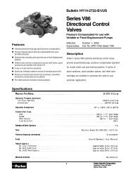
<strong>Directional</strong> <strong>Control</strong> <strong>Valve</strong>s<br />
<strong>P70</strong><br />
List of contents<br />
Page<br />
General Information........................................................................................................4<br />
Open Centre Systems, OC, (<strong>Valve</strong> with open centre, <strong>P70</strong>CF)........................................5<br />
<strong>Control</strong> characteristics.....................................................................................................5<br />
Constant-pressure systems, CP, CPU, (<strong>Valve</strong> with closed centre, <strong>P70</strong>CP)....................6<br />
<strong>Control</strong> characteristics.....................................................................................................6<br />
Load sensing systems, LS, (<strong>Valve</strong> with load sensing, <strong>P70</strong>LS)........................................7<br />
<strong>Control</strong> characteristics.....................................................................................................7<br />
System connection..........................................................................................................8<br />
A. Power beyond connection, multi-valve system, <strong>P70</strong>CF only.................................8<br />
B. Power beyond connection, single-valve system, <strong>P70</strong>CF only...............................8<br />
C. Parallel connection, multi-valve system................................................................9<br />
Technical Data...............................................................................................................10<br />
Environmental characteristics.......................................................................................11<br />
Hydraulic circuit diagram showing basic functions, standard valve...............................12<br />
Hydraulic circuit diagram showing basic functions<br />
(actuators with closed spool end)..................................................................................13<br />
Inlet Section..................................................................................................................14<br />
Type of inlet section [15]..........................................................................................14<br />
Main pressure relief valve [16]................................................................................16<br />
Pressure setting [17]...............................................................................................16<br />
Pump unloading [22]...............................................................................................16<br />
External pump unloading or multi-level main pressure relief function.....................17<br />
Tank connection T2 [25]..........................................................................................17<br />
Pump connection P1 [26]........................................................................................17<br />
Pump connection P2 [27]........................................................................................17<br />
Mid-inlet section [90].....................................................................................................18<br />
Options, mid-inlet [93].............................................................................................19<br />
Main pressure relief valve [94]................................................................................19<br />
Pressure setting [98]...............................................................................................19<br />
End Section...................................................................................................................20<br />
Type of end section [30]..........................................................................................20<br />
Tank connection T1 [33]..........................................................................................20<br />
Tank connection T3 [34]..........................................................................................20<br />
Series-connection function [36]...............................................................................20<br />
Reducing valve [37].................................................................................................21<br />
Pilot-oil strainer [39]................................................................................................21<br />
Separate tank connection for pilot circuit [40].........................................................21<br />
Spool Sections..............................................................................................................22<br />
Type of spool section [47]........................................................................................22<br />
Lever bracket [51]....................................................................................................23<br />
Spool actuators [50]................................................................................................24<br />
Hand-operated spool actuators with open spool end........................................24<br />
Remote controlled ON/OFF spool actuators with open spool end....................24<br />
Remote controlled proportional spool actuators with closed spool end............25<br />
Spool position indicator [52]..............................................................................28<br />
Spool function [60]..................................................................................................29<br />
Spool designation [69].............................................................................................29<br />
Pressure gallery [66]...............................................................................................29<br />
Choice of Spool.......................................................................................................29<br />
Pressure limiters in work ports [76A/B]...................................................................30<br />
Port relief valve [76].................................................................................................30<br />
Function blocks (manifolds)...........................................................................................31<br />
Connectors, electrical....................................................................................................31<br />
Hand levers for open and closed spool-actuators................................................... 32-33<br />
Dimensional drawings, standard valve..........................................................................34<br />
Dimensional drawings, model with closed spool end....................................................35<br />
Dimensional drawings, spool actuators................................................................... 36-38<br />
[00] refers to item numbers in customer specification.<br />
<br />
Parker Hannifin<br />
Mobile <strong>Control</strong>s Division Europe<br />
Borås, Sweden