Directional Control Valve P70 - Oleosistemas
Directional Control Valve P70 - Oleosistemas
Directional Control Valve P70 - Oleosistemas
Create successful ePaper yourself
Turn your PDF publications into a flip-book with our unique Google optimized e-Paper software.
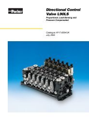
Catalogue HY17-8546/UK<br />
Catalogue Information<br />
Catalogue layout<br />
This catalogue is designed to give an overview of the <strong>P70</strong><br />
directional valve and to show how it can be customised to meet<br />
your needs exactly. Apart from general information and basic<br />
technical data therefore, the catalogue contains descriptions of<br />
the variety of options available for the different function areas<br />
of the valve. After you have studied the options and made your<br />
selection, we will tailor your valve to meet your operating and<br />
control criteria.<br />
Each function area is given as a subheading, followed by<br />
a brief description. When several optional functions are available<br />
for the same function area, the subheading is followed by<br />
an “Item number” in square brackets, e.g. Main pressure relief<br />
valve [16]. This is followed by a series of coded options, e.g. PS,<br />
<strong>Directional</strong> <strong>Control</strong> <strong>Valve</strong>s<br />
<strong>P70</strong><br />
PB, Y, together with a brief description of what each code represents.<br />
Alternatively, one or more pressure, flow or voltage options<br />
are given.<br />
On pages 12 and 13 there are general circuit diagrams<br />
showing the basic functions of the <strong>P70</strong> valve, together with the<br />
item numbers and letter codes used to represent them. Naturally,<br />
the same item numbers and letter codes are used in all<br />
sub-circuit diagrams that appear elsewhere in the catalogue in<br />
conjunction with descriptions of the respective function areas. All<br />
sub-circuit diagrams have been extracted from the general circuit<br />
diagram. Please note that, unless otherwise stated, all sections<br />
and views of the valves have been drawn as seen from the inlet<br />
section.<br />
How to order your valve<br />
Parker has developed a computer program to specify the <strong>P70</strong>,<br />
so that the configuration of your valve can be optimised to give<br />
maximum performance in your particular hydraulic system.<br />
Based on the demands on each individual machine function,<br />
the computer specifies the configuration of the valve to give<br />
optimal performance. It also generates complete documentation<br />
for your valve in the form of a detailed specification and hydraulic<br />
circuit diagram.<br />
The program also generates a unique product designation that<br />
is subsequently stamped into the data plate on your valve. Your<br />
customised valve specifications remain on our database to facilitate<br />
rapid identification of your valve in the event of re-ordering or<br />
servicing.<br />
Early consultation with Parker saves time and money<br />
Our experienced application engineers have in-depth knowledge<br />
of the different types of hydraulic system and the ways in which<br />
they work. They are at your disposal to offer qualified advice on<br />
the various combinations of functions and control characteristics<br />
you may require, and to advise how to obtain the best possible<br />
economy.<br />
By consulting Parker early in the project planning stage, you are<br />
assured of a comprehensive hydraulic system that will give your<br />
machine the best possible operating and control characteristics,<br />
together with outstanding economy.<br />
Subject to alteration without prior notice. The graphs and<br />
diagrams in this catalogue are typical examples only. While the<br />
contents of the catalogue are updated continually, the validity<br />
of the information given should always be confirmed. For more<br />
detailed information, please contact Parker Hannifin.<br />
Conversion factors<br />
1 kg = 2.2046 lb<br />
1 N = 0.22481 lbf<br />
1 bar = 14.504 psi<br />
1 l = 0.21997 UK gallon<br />
1 l = 0.26417 US gallon<br />
1 cm 3 = 0.061024 in 3<br />
1 m = 3.2808 feet<br />
1 mm = 0.03937 in<br />
9/5 °C + 32 = °F<br />
<br />
Parker Hannifin<br />
Mobile <strong>Control</strong>s Division Europe<br />
Borås, Sweden


