Directional Control Valve P70 - Oleosistemas
Directional Control Valve P70 - Oleosistemas
Directional Control Valve P70 - Oleosistemas

You also want an ePaper? Increase the reach of your titles
YUMPU automatically turns print PDFs into web optimized ePapers that Google loves.
Catalogue HY17-8546/UK<br />
Hydraulic circuit diagram<br />
<strong>Directional</strong> <strong>Control</strong> <strong>Valve</strong>s<br />
<strong>P70</strong><br />
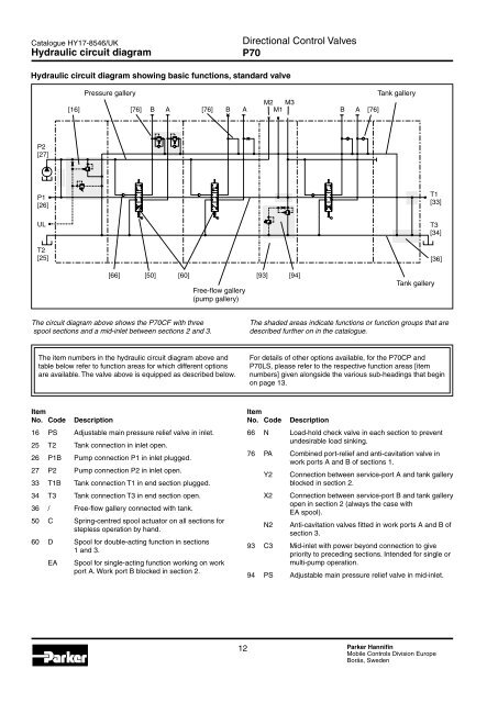
Hydraulic circuit diagram showing basic functions, standard valve<br />
[16]<br />
Pressure gallery<br />
M2 M3<br />
[76] B A [76] B A M1<br />
B A<br />
[76]<br />
Tank gallery<br />
P2<br />
[27]<br />
P1<br />
[26]<br />
T1<br />
[33]<br />
UL<br />
T2<br />
[25]<br />
T3<br />
[34]<br />
[36]<br />
[66]<br />
[50] [60]<br />
[93]<br />
Free-flow gallery<br />
(pump gallery)<br />
[94]<br />
Tank gallery<br />
The circuit diagram above shows the <strong>P70</strong>CF with three<br />
spool sections and a mid-inlet between sections 2 and 3.<br />
The shaded areas indicate functions or function groups that are<br />
described further on in the catalogue.<br />
The item numbers in the hydraulic circuit diagram above and<br />
table below refer to function areas for which different options<br />
are available. The valve above is equipped as described below.<br />
For details of other options available, for the <strong>P70</strong>CP and<br />
<strong>P70</strong>LS, please refer to the respective function areas [item<br />
numbers] given alongside the various sub-headings that begin<br />
on page 13.<br />
Item<br />
No. Code<br />
Description<br />
16 PS Adjustable main pressure relief valve in inlet.<br />
25 T2 Tank connection in inlet open.<br />
26 P1B Pump connection P1 in inlet plugged.<br />
27 P2 Pump connection P2 in inlet open.<br />
33 T1B Tank connection T1 in end section plugged.<br />
34 T3 Tank connection T3 in end section open.<br />
36 / Free-flow gallery connected with tank.<br />
50 C Spring-centred spool actuator on all sections for<br />
stepless operation by hand.<br />
60 D Spool for double-acting function in sections<br />
1 and 3.<br />
EA<br />
Spool for single-acting function working on work<br />
port A. Work port B blocked in section 2.<br />
Item<br />
No. Code<br />
Description<br />
66 N Load-hold check valve in each section to prevent<br />
undesirable load sinking.<br />
76 PA Combined port-relief and anti-cavitation valve in<br />
work ports A and B of sections 1.<br />
Y2<br />
X2<br />
N2<br />
Connection between service-port A and tank gallery<br />
blocked in section 2.<br />
Connection between service-port B and tank gallery<br />
open in section 2 (always the case with<br />
EA spool).<br />
Anti-cavitation valves fitted in work ports A and B of<br />
section 3.<br />
93 C3 Mid-inlet with power beyond connection to give<br />
priority to preceding sections. Intended for single or<br />
multi-pump operation.<br />
94 PS Adjustable main pressure relief valve in mid-inlet.<br />
12 Parker Hannifin<br />
Mobile <strong>Control</strong>s Division Europe<br />
Borås, Sweden