Directional Control Valve P70 - Oleosistemas
Directional Control Valve P70 - Oleosistemas
Directional Control Valve P70 - Oleosistemas

Create successful ePaper yourself
Turn your PDF publications into a flip-book with our unique Google optimized e-Paper software.
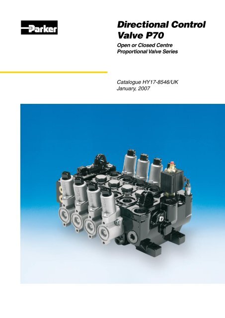
<strong>Directional</strong> <strong>Control</strong><br />
<strong>Valve</strong> <strong>P70</strong><br />
Open or Closed Centre<br />
Proportional <strong>Valve</strong> Series<br />
Catalogue HY17-8546/UK<br />
January, 2007
Catalogue HY17-8546/UK<br />
Catalogue Information<br />
Catalogue layout<br />
This catalogue is designed to give an overview of the <strong>P70</strong><br />
directional valve and to show how it can be customised to meet<br />
your needs exactly. Apart from general information and basic<br />
technical data therefore, the catalogue contains descriptions of<br />
the variety of options available for the different function areas<br />
of the valve. After you have studied the options and made your<br />
selection, we will tailor your valve to meet your operating and<br />
control criteria.<br />
Each function area is given as a subheading, followed by<br />
a brief description. When several optional functions are available<br />
for the same function area, the subheading is followed by<br />
an “Item number” in square brackets, e.g. Main pressure relief<br />
valve [16]. This is followed by a series of coded options, e.g. PS,<br />
<strong>Directional</strong> <strong>Control</strong> <strong>Valve</strong>s<br />
<strong>P70</strong><br />
PB, Y, together with a brief description of what each code represents.<br />
Alternatively, one or more pressure, flow or voltage options<br />
are given.<br />
On pages 12 and 13 there are general circuit diagrams<br />
showing the basic functions of the <strong>P70</strong> valve, together with the<br />
item numbers and letter codes used to represent them. Naturally,<br />
the same item numbers and letter codes are used in all<br />
sub-circuit diagrams that appear elsewhere in the catalogue in<br />
conjunction with descriptions of the respective function areas. All<br />
sub-circuit diagrams have been extracted from the general circuit<br />
diagram. Please note that, unless otherwise stated, all sections<br />
and views of the valves have been drawn as seen from the inlet<br />
section.<br />
How to order your valve<br />
Parker has developed a computer program to specify the <strong>P70</strong>,<br />
so that the configuration of your valve can be optimised to give<br />
maximum performance in your particular hydraulic system.<br />
Based on the demands on each individual machine function,<br />
the computer specifies the configuration of the valve to give<br />
optimal performance. It also generates complete documentation<br />
for your valve in the form of a detailed specification and hydraulic<br />
circuit diagram.<br />
The program also generates a unique product designation that<br />
is subsequently stamped into the data plate on your valve. Your<br />
customised valve specifications remain on our database to facilitate<br />
rapid identification of your valve in the event of re-ordering or<br />
servicing.<br />
Early consultation with Parker saves time and money<br />
Our experienced application engineers have in-depth knowledge<br />
of the different types of hydraulic system and the ways in which<br />
they work. They are at your disposal to offer qualified advice on<br />
the various combinations of functions and control characteristics<br />
you may require, and to advise how to obtain the best possible<br />
economy.<br />
By consulting Parker early in the project planning stage, you are<br />
assured of a comprehensive hydraulic system that will give your<br />
machine the best possible operating and control characteristics,<br />
together with outstanding economy.<br />
Subject to alteration without prior notice. The graphs and<br />
diagrams in this catalogue are typical examples only. While the<br />
contents of the catalogue are updated continually, the validity<br />
of the information given should always be confirmed. For more<br />
detailed information, please contact Parker Hannifin.<br />
Conversion factors<br />
1 kg = 2.2046 lb<br />
1 N = 0.22481 lbf<br />
1 bar = 14.504 psi<br />
1 l = 0.21997 UK gallon<br />
1 l = 0.26417 US gallon<br />
1 cm 3 = 0.061024 in 3<br />
1 m = 3.2808 feet<br />
1 mm = 0.03937 in<br />
9/5 °C + 32 = °F<br />
<br />
Parker Hannifin<br />
Mobile <strong>Control</strong>s Division Europe<br />
Borås, Sweden
Catalogue HY17-8546/UK<br />
Contents<br />
<strong>Directional</strong> <strong>Control</strong> <strong>Valve</strong>s<br />
<strong>P70</strong><br />
List of contents<br />
Page<br />
General Information........................................................................................................4<br />
Open Centre Systems, OC, (<strong>Valve</strong> with open centre, <strong>P70</strong>CF)........................................5<br />
<strong>Control</strong> characteristics.....................................................................................................5<br />
Constant-pressure systems, CP, CPU, (<strong>Valve</strong> with closed centre, <strong>P70</strong>CP)....................6<br />
<strong>Control</strong> characteristics.....................................................................................................6<br />
Load sensing systems, LS, (<strong>Valve</strong> with load sensing, <strong>P70</strong>LS)........................................7<br />
<strong>Control</strong> characteristics.....................................................................................................7<br />
System connection..........................................................................................................8<br />
A. Power beyond connection, multi-valve system, <strong>P70</strong>CF only.................................8<br />
B. Power beyond connection, single-valve system, <strong>P70</strong>CF only...............................8<br />
C. Parallel connection, multi-valve system................................................................9<br />
Technical Data...............................................................................................................10<br />
Environmental characteristics.......................................................................................11<br />
Hydraulic circuit diagram showing basic functions, standard valve...............................12<br />
Hydraulic circuit diagram showing basic functions<br />
(actuators with closed spool end)..................................................................................13<br />
Inlet Section..................................................................................................................14<br />
Type of inlet section [15]..........................................................................................14<br />
Main pressure relief valve [16]................................................................................16<br />
Pressure setting [17]...............................................................................................16<br />
Pump unloading [22]...............................................................................................16<br />
External pump unloading or multi-level main pressure relief function.....................17<br />
Tank connection T2 [25]..........................................................................................17<br />
Pump connection P1 [26]........................................................................................17<br />
Pump connection P2 [27]........................................................................................17<br />
Mid-inlet section [90].....................................................................................................18<br />
Options, mid-inlet [93].............................................................................................19<br />
Main pressure relief valve [94]................................................................................19<br />
Pressure setting [98]...............................................................................................19<br />
End Section...................................................................................................................20<br />
Type of end section [30]..........................................................................................20<br />
Tank connection T1 [33]..........................................................................................20<br />
Tank connection T3 [34]..........................................................................................20<br />
Series-connection function [36]...............................................................................20<br />
Reducing valve [37].................................................................................................21<br />
Pilot-oil strainer [39]................................................................................................21<br />
Separate tank connection for pilot circuit [40].........................................................21<br />
Spool Sections..............................................................................................................22<br />
Type of spool section [47]........................................................................................22<br />
Lever bracket [51]....................................................................................................23<br />
Spool actuators [50]................................................................................................24<br />
Hand-operated spool actuators with open spool end........................................24<br />
Remote controlled ON/OFF spool actuators with open spool end....................24<br />
Remote controlled proportional spool actuators with closed spool end............25<br />
Spool position indicator [52]..............................................................................28<br />
Spool function [60]..................................................................................................29<br />
Spool designation [69].............................................................................................29<br />
Pressure gallery [66]...............................................................................................29<br />
Choice of Spool.......................................................................................................29<br />
Pressure limiters in work ports [76A/B]...................................................................30<br />
Port relief valve [76].................................................................................................30<br />
Function blocks (manifolds)...........................................................................................31<br />
Connectors, electrical....................................................................................................31<br />
Hand levers for open and closed spool-actuators................................................... 32-33<br />
Dimensional drawings, standard valve..........................................................................34<br />
Dimensional drawings, model with closed spool end....................................................35<br />
Dimensional drawings, spool actuators................................................................... 36-38<br />
[00] refers to item numbers in customer specification.<br />
<br />
Parker Hannifin<br />
Mobile <strong>Control</strong>s Division Europe<br />
Borås, Sweden
Catalogue HY17-8546/UK<br />
General Information<br />
<strong>Directional</strong> <strong>Control</strong> <strong>Valve</strong>s<br />
<strong>P70</strong><br />
The <strong>P70</strong> directional valve is of modular<br />
construction. It is designed for many<br />
different applications and used extensively<br />
in machines such as lorry cranes, miniexcavators,<br />
small wheeled loaders and<br />
concrete placing cranes. The <strong>P70</strong> is available<br />
in three different versions: the <strong>P70</strong>CF<br />
with an open centre for fixed pumps, the<br />
<strong>P70</strong>CP with a closed centre for variable<br />
displacement pumps and the <strong>P70</strong>LS<br />
with a closed centre, coupled with a load<br />
sensing signal, to the variable displacement<br />
pump.<br />
Compact system construction<br />
The <strong>P70</strong> offers unique possibilities for the<br />
integration of application-adapted functions<br />
to give compact and total system<br />
solutions for a wide range of mobile<br />
machines.<br />
Freedom in machine design<br />
In order to give the system designer a<br />
greater level of flexibility and freedom,<br />
the valve is designed to be either directly<br />
operated, or controlled by electric, pneumatic<br />
or hydraulic remote controls. A<br />
combination of these direct, and remote<br />
controls, can be utilised allowing a greater<br />
degree of component location and pilot<br />
media options.<br />
Economy<br />
Thanks to its modular construction, the<br />
<strong>P70</strong> can be optimised for both simple<br />
and complex functions. The possibility of<br />
integrating total function solutions gives<br />
low overall system costs. The valve can be<br />
modified or expanded as necessary to suit<br />
the needs of the customer.<br />
Safety<br />
The valve is of robust construction, with<br />
each function unitised. This facilitates both<br />
training and servicing and contributes<br />
greatly to safety. Moreover, the valve can<br />
be fitted with a special inlet section that<br />
enables an emergency STOP function to<br />
be incorporated into the valve to meet the<br />
demands of the EC Machinery Directive in<br />
a uniquely simple way.<br />
Design<br />
The <strong>P70</strong> is a stackable valve system and<br />
can be supplied in combinations of 1 to<br />
10 spool sections, additionally manifold<br />
sections can also be utilised to add further<br />
system flexibility. The valve is designed for<br />
system pressures of up to 320 bar.<br />
The maximum recommended flow<br />
rates for the <strong>P70</strong>CF, CP and LS are 70, 90<br />
and 90 l/min respectively, depending on<br />
how the valve is equipped. There are also<br />
a wide range of different available spools,<br />
enabling specific control characteristics to<br />
be optimised.<br />
Benefits<br />
• Low fuel consumption and heat generation<br />
with low pressure drops.<br />
• Productivity - our complete application<br />
adapted spool range will optimise each<br />
machine function to provide unsurpassed<br />
driver control and productivity.<br />
• Precision - excellent repeatability especially<br />
during simultaneous operation<br />
by having machined land edges in the<br />
valve housing.<br />
<br />
• Long service life – e.g. open spool<br />
ends with rubber bellows increase<br />
the service life of both spools and<br />
spool seals. Quality materials and<br />
high manufacturing precision ensure<br />
a superior product<br />
• Smooth machine feel with less driver<br />
fatigue with low lever forces.<br />
• Integrated functions – by combining<br />
<strong>P70</strong> and flanged on manifolds additional<br />
functionality is effectively<br />
provided in the minimum space envelope<br />
and at the same time with reduced<br />
hosing complexity and cost.<br />
• Flexibility – options allow for connection<br />
of more than one pump or valve<br />
in a system to increase the range of<br />
applications <strong>P70</strong> can be used on.<br />
• Security - <strong>P70</strong> prevents undesirable<br />
load sinking during simultaneous<br />
operation with separate check valves<br />
positioned in each spool section.<br />
• Safety - <strong>P70</strong> gives an individual<br />
maximum pressure limitation with<br />
separate port relief valves positioned in<br />
each work port.<br />
• Minimized downtime with simple<br />
design, which makes <strong>P70</strong> easy to<br />
service. An emphasis on simplicity<br />
of design makes the <strong>P70</strong> the best in<br />
class.<br />
Parker Hannifin<br />
Mobile <strong>Control</strong>s Division Europe<br />
Borås, Sweden
Catalogue HY17-8546/UK<br />
System description<br />
<strong>Directional</strong> <strong>Control</strong> <strong>Valve</strong>s<br />
<strong>P70</strong><br />
B<br />
A<br />
PF<br />
PS<br />
P2B<br />
T4<br />
P1<br />
T1<br />
UL<br />
T2B<br />
T3B<br />
TP<br />
Principle circuit diagram for valve with open centre<br />
q(l/min)<br />
Flow rate in work port<br />
Open centre systems, OC<br />
(<strong>Valve</strong> with open centre, <strong>P70</strong>CF)<br />
The pump in a constant-flow system has fixed displacement,<br />
which means that the flow remains constant for a given engine<br />
speed. The pressure, however, changes to meet demand.<br />
Any oil that is not directed out to a consumer flows back to<br />
tank via the free-flow gallery (open centre) in the valve. When<br />
several lifting functions are activated simultaneously, the pressure<br />
is determined by the heaviest load. Simultaneously operated<br />
functions should therefore have roughly the same pressure<br />
needs, or be divided into separate pump circuits to minimise<br />
cross-functional interference and give good operating economy.<br />
Provided that most of the pump capacity is used, the OC system<br />
is very economical. For this reason, it is important for the system<br />
to have a pump of the right capacity.<br />
<strong>Control</strong> characteristics<br />
In hand-operated valves, there is no clear-cut relationship<br />
between the stroke of the lever and the speed of the load. The<br />
speed of the load will depend on the following four variables: its<br />
weight, the pump flow, the direction of force and the direction<br />
of movement of any other simultaneously operated loads. The<br />
reason for this is that, when more passages are opened subsequently,<br />
the flows redistribute themselves so that the pressure<br />
drop in all flow paths becomes equal.<br />
The <strong>P70</strong>CF’s customised valve spools give considerably<br />
better simultaneous-operating characteristics. In some cases, this<br />
can result in higher energy losses during the fine-metering stage.<br />
Our directional valves, which are designed to be remote<br />
controlled, are usually fitted with pressure compensated spools.<br />
This means that the regulated flow remains constant for a given<br />
lever stroke, regardless of any pressure variations within the<br />
system.<br />
80<br />
60<br />
40<br />
20<br />
0<br />
0<br />
250 bar lower<br />
150 bar<br />
50 bar<br />
50 bar lift<br />
150 bar<br />
250 bar<br />
20 40 60 80 100<br />
Lever stroke in %<br />
q pump<br />
In <strong>P70</strong>CF valves with hand-operated spools, speed is affected by<br />
the weight of the load, i.e. the heavier the lift load, the longer the<br />
lever stroke needed before the load starts to move. Conversely,<br />
the heavier the load to be lowered, the faster the lowering<br />
sequence.<br />
q(l/min)<br />
Flow rate in work port<br />
80<br />
60<br />
40<br />
250 bar lower<br />
50 bar<br />
q pump<br />
20<br />
50 bar lift<br />
250 bar<br />
0<br />
0 20 40 60 80 100<br />
Lever stroke in %<br />
In the <strong>P70</strong>CF equipped with FPC, PC, ECS and ECH closed<br />
spool-actuators, the spools are pressure compensated, with the<br />
result that the load’s influence on speed is negligible.<br />
<br />
Parker Hannifin<br />
Mobile <strong>Control</strong>s Division Europe<br />
Borås, Sweden
Catalogue HY17-8546/UK<br />
System description<br />
<strong>Directional</strong> <strong>Control</strong> <strong>Valve</strong>s<br />
<strong>P70</strong><br />
B<br />
A<br />
PF<br />
PS<br />
P2<br />
T4<br />
P1<br />
T1<br />
UL<br />
T2B<br />
T3B<br />
TPB<br />
Principle circuit diagram for valve with closed centre<br />
q(l/min)<br />
Flow rate in work port<br />
Constant-pressure systems, CP, CPU<br />
(<strong>Valve</strong> with closed centre, <strong>P70</strong>CP)<br />
Constant pressure systems are supplied by a variable displacement<br />
pump. This type of pump is controlled by a regulator which<br />
ensures that the pressure is kept constant whilst the flow varies<br />
to suit the demand. The constant-pressure system is of relatively<br />
simple construction, with an uncomplicated valve. However, the<br />
variable pump is more advanced than pumps with fixed displacement.<br />
To maintain the constant-pressure system’s superior control<br />
characteristics, the pump must be dimensioned to give the sum of<br />
the maximum flows for simultaneously operated functions. If the<br />
pressure cannot be maintained, the valve loses its control characteristics<br />
quickly and the actuated functions start to influence each<br />
other, with the lightest loads receiving the most oil. However, this<br />
system is less susceptible to pressure drops, as the pressure<br />
corresponding to the machine capacity is always available.<br />
There are two main types of pump on the market. What distinguishes<br />
them from each other is where the signal that influences<br />
the pump regulator comes from. One pump type takes the signal<br />
internally, whereas the other requires a signal from the directional<br />
valve. The <strong>P70</strong>CP can be used equally efficiently with either type.<br />
<strong>Control</strong> characteristics<br />
A correctly specified <strong>P70</strong>CP gives excellent control characteristics,<br />
with different functions having no affect upon each other. The<br />
system also has great anti cavitation characteristics which allow a<br />
lowering movement to change to a lifting one without delay.<br />
The maximum speed of each <strong>P70</strong>CP function is determined<br />
by the design of the spool and the pressure demands of the<br />
load. The <strong>P70</strong>CP can be fitted with a range of Parker’s specifically<br />
designed spools, allowing them to be exactly suited to the<br />
customers speed and function requirements. In the <strong>P70</strong>CP too,<br />
remote controlled spools are pressure compensated. However,<br />
if the flow requirements of the system exceed the maximum<br />
capacity of the pump, the pressure level cannot be maintained<br />
and the normally very good control characteristics deteriorate.<br />
80<br />
60<br />
40<br />
20<br />
0<br />
0<br />
150 bar lower<br />
100 bar<br />
50 bar<br />
50 bar lift<br />
150 bar<br />
20 40 60 80 100<br />
Lever stroke in %<br />
In the <strong>P70</strong>CP with hand-operated spools, all loads start moving<br />
at the same point, regardless of the size and direction of the load.<br />
The size of the load does, however, affect the slope of the curve<br />
to some extent.<br />
q(l/min)<br />
80<br />
60<br />
40<br />
20<br />
0<br />
0<br />
Flow rate in work port<br />
lift<br />
250 bar lower<br />
50 bar<br />
q pump<br />
20 40 60 80 100<br />
Lever stroke in %<br />
In the <strong>P70</strong>CP equipped with FPC, PC, ECS and ECH closed<br />
spool-actuators, the spools are pressure compensated, with the<br />
result that the load’s influence on speed is negligible.<br />
<br />
Parker Hannifin<br />
Mobile <strong>Control</strong>s Division Europe<br />
Borås, Sweden
Catalogue HY17-8546/UK<br />
System description<br />
<strong>Directional</strong> <strong>Control</strong> <strong>Valve</strong>s<br />
<strong>P70</strong><br />
B<br />
A<br />
PF<br />
PS<br />
P2<br />
T4<br />
P1<br />
UL<br />
T2B<br />
T3<br />
TPB<br />
Principle circuit diagram for valve with load sensing<br />
Load sensing systems, LS<br />
(<strong>Valve</strong> with load sensing, <strong>P70</strong>LS)<br />
In the load sensing system both pressure and flow are modulated<br />
to match immediate needs from the consumers, with a pressure<br />
level corresponding to the heaviest load at that moment.<br />
When supplied from a variable displacement pump the<br />
directional control valve sends a load signal to the pump control<br />
regulator, which adjusts the pump output to maintain a constant<br />
pressure difference between the pump output and the load<br />
signal.<br />
In the <strong>P70</strong>LS, the free flow gallery is used to collect the load<br />
pressures from all the motor ports of the valve. The signal of the<br />
highest load is then delivered to the variable pump regulator.<br />
In order to achieve good operating characteristics, the pump<br />
should be sized to deliver flow equal to the sum of all simultaneously<br />
working functions. If the control pressure difference cannot<br />
be maintained, the operating characteristics of the valve can<br />
quickly deteriorate, and the controlled functions will influence<br />
each other, progressively resulting in lower loads receiving more<br />
flow than the higher ones.<br />
In common with a constant flow system, simultaneously<br />
working functions should have approximately the same pressure<br />
requirement or they should be divided into separate circuits for<br />
high operating efficiency.<br />
q(l/min)<br />
80<br />
60<br />
40<br />
20<br />
0<br />
0<br />
Flow rate in work port<br />
lift<br />
250 bar lower<br />
50 bar<br />
20 40 60 80 100<br />
Lever stroke in %<br />
q pump<br />
In the <strong>P70</strong>LS equipped with PC, ECS and ECH closed spoolactuators,<br />
the spools are pressure compensated, with the result<br />
that the load’s influence on speed is negligible.<br />
Operating characteristics<br />
With a correctly adjusted <strong>P70</strong>LS valve, the operating characteristics<br />
of the system are very good. The constant differential<br />
pressure maintained by the pump means that the flow to the<br />
heaviest load in a load sensing system is always pressure<br />
compensated.<br />
However, load sensing does not mean that other functions<br />
are pressure compensated. To achieve good operating characteristics,<br />
the spools should be adapted for each function.<br />
<strong>P70</strong>LS valves are designed for remote control and have<br />
pressure-compensated spools. This means that the regulated<br />
flow remains constant at a certain lever position, regardless of<br />
pressure variations in the system.<br />
<br />
Parker Hannifin<br />
Mobile <strong>Control</strong>s Division Europe<br />
Borås, Sweden
Catalogue HY17-8546/UK<br />
System connection<br />
<strong>Directional</strong> <strong>Control</strong> <strong>Valve</strong>s<br />
<strong>P70</strong><br />
Below are a few examples of how the <strong>P70</strong> can be connected up.<br />
A. Power beyond connection, multi-valve system,<br />
<strong>P70</strong>CF only<br />
The pump is connected to the first valve. Flow that is not directed<br />
to a consumer via the first valve continues to the next valve. The<br />
first valve therefore has priority, i.e. in the event of full spool actuation<br />
in the first valve, no flow continues to the next valve.<br />
Inlet section Spool section End section<br />
S-function*<br />
If an additional pump is connected to valve 2, then valve 2<br />
receives the flow from pump 2 plus any residual flow from valve 1.<br />
S-function*<br />
B. Power beyond connection, single-valve system,<br />
<strong>P70</strong>CF only<br />
The pump is connected to the inlet section. Flow that is not<br />
directed out to consumers connected before the mid-inlet section<br />
continues to consumers connected after the mid-inlet section.<br />
This means that the first spool sections have priority, i.e. in the<br />
event of full spool actuation in a section before the mid-inlet<br />
section, no flow continues to the sections after the mid-inlet<br />
section.<br />
Mid-inlet section<br />
If an additional pump is connected to the mid-inlet section, then<br />
subsequent sections will receive the flow from pump 2 plus any<br />
flow from pump 1 that has not been used by the sections before<br />
the mid-inlet section.<br />
Mid-inlet section<br />
= Alternative connection<br />
= Signal line<br />
* The different functions are described in more detail on<br />
pages 14 - 21.<br />
<br />
Parker Hannifin<br />
Mobile <strong>Control</strong>s Division Europe<br />
Borås, Sweden
Catalogue HY17-8546/UK<br />
System connection<br />
<strong>Directional</strong> <strong>Control</strong> <strong>Valve</strong>s<br />
<strong>P70</strong><br />
C. Parallel connection, multi-valve system<br />
In parallel connection, the same pump is connected to two<br />
or more valves. The function is the same as if the pump were<br />
connected to a single large valve.<br />
Parallel connection, fixed pump (OC), <strong>P70</strong>CF<br />
S-function*<br />
L-function*<br />
Parallel connection, variable pump (CP), <strong>P70</strong>CP<br />
L-function [27]<br />
L-function [27]<br />
Parallel connection, variable pump (CPU, LS), <strong>P70</strong>CP, <strong>P70</strong>LS<br />
CUI- or L-function.<br />
ST-nipple [33]<br />
L-function [27]<br />
= Alternative connection<br />
= Signal line<br />
* The different functions are described in more detail on<br />
pages 14 -21.<br />
<br />
Parker Hannifin<br />
Mobile <strong>Control</strong>s Division Europe<br />
Borås, Sweden
Catalogue HY17-8546/UK<br />
Technical Data<br />
<strong>Directional</strong> <strong>Control</strong> <strong>Valve</strong>s<br />
<strong>P70</strong><br />
Connection for hydraulic<br />
remote control, PC [50]. Actuation<br />
pump to work port B<br />
Connections in<br />
mid-inlet section,<br />
M1, M2, M3 [90]<br />
Main pressure relief<br />
valve in mid-inlet<br />
section [94]<br />
Spool actuator C [50]<br />
Work port B,<br />
section 2<br />
Spool actuator ECH and ECH<br />
with spool position indicator<br />
SI. Actuation pump to work<br />
port B<br />
Inlet section<br />
Tank connection<br />
T2 [25]<br />
Tank connection<br />
T3 [34]<br />
Pump connection<br />
P2 [27]<br />
Pump connection<br />
P1 [26]<br />
Tank connection<br />
T1 [33]<br />
Main pressure<br />
relief valve [16]<br />
End section<br />
Work port A,<br />
section 1<br />
Connection for hydraulic<br />
remote control, PC [50].<br />
Actuation pump to work<br />
port A<br />
Mid-inlet section<br />
Spool actuator ECH.<br />
Actuation pump to<br />
work port A<br />
Pressures<br />
Pump connection max. 320 bar* (4640 psi)<br />
Work ports<br />
max. 350 bar* (5075 psi)<br />
Tank connection, static max. 10 bar (145 psi)<br />
Flow rates (recommended)<br />
<strong>P70</strong>CF. Pump connection max. 70 l/min (18.5 USgpm)**<br />
<strong>P70</strong>CP. Pump connection max. 90 l/min (23.8 USgpm)**<br />
<strong>P70</strong>LS. Pump connection max. 90 l/min (23.8 USgpm)**<br />
<strong>P70</strong>CF. Return fr. work port max. 100 l/min (26.5 USgpm)**<br />
<strong>P70</strong>CP. Return fr. work port max. 125 l/min (33.0 USgpm)**<br />
<strong>P70</strong>LS. Return fr. work port max. 125 l/min (33.0 USgpm)**<br />
Internal pilot pressure<br />
Fixed setting<br />
35 bar (508 psi)<br />
Leakage from work port over spool<br />
From A or B port: max. 75 cm 3 /min (4.58 cu.in/min) at 250 bar<br />
(3625 psi), oil temperature 50 °C (122 °F) and viscosity<br />
30 mm 2 /s (cSt).<br />
Weight<br />
Since the weight will vary somewhat depending on the configuration<br />
of the valve, the values below are approximate.<br />
<strong>Valve</strong> housing inclusive of spool, pressure relief valve etc.<br />
and inclusive of spool actuator.<br />
Standard inlet section<br />
.7 kg (6.0 lb)<br />
Inlet with bypass<br />
4.9 kg (10.8 lb)<br />
Single spool section C<br />
3.5 kg (7.7 lb)<br />
Double spool section C<br />
7.2 kg (15.9 lb)<br />
Single spool section ECH<br />
4.1 kg (9.0 lb)<br />
Double spool section ECH<br />
8.4 kg (18.5 lb)<br />
Mid-inlet section<br />
.7 kg (6.0 lb)<br />
End section with pilot<br />
pressure supply<br />
3.8 kg (8.4 lb)<br />
End section<br />
.7 kg (6.0 lb)<br />
Connections<br />
Unless stated otherwise, all standard connections are available<br />
in two versions: G-version (BSP pipe thread) for flat seal (type<br />
Tredo) as per ISO 228/1 and UNF-version for O-ring seal as per<br />
SAE J1926/1.<br />
Connection Location G-version UNF-version<br />
P1, P2 Inlet section G1/2 7/8-14 UNF-2B<br />
PX Inlet section, IU G1/4 9/16-18 UNF-2B<br />
T2 Inlet section, I G1/2 7/8-14 UNF-2B<br />
T2 Inlet section, IU G3/4 1-1/16-12 UN-2B<br />
UL Inlet section G1/4 9/16-18 UNF-2B<br />
M1, M2, M3 Mid-inlet G1/2 7/8-14 UNF-2B<br />
Work ports<br />
A and B Spool section G1/2 7/8-14 UNF-2B<br />
PC Spool section G1/4 9/16-18 UNF-2B<br />
T1, T3 End section G1/2 7/8-14 UNF-2B<br />
T4 End section G1/4 9/16-18 UNF-2B<br />
TP End section G1/4 9/16-18 UNF-2B<br />
PS End section G1/4 9/16-18 UNF-2B<br />
PF End section G1/4 9/16-18 UNF-2B<br />
male connector<br />
Surface treatment (painted) [07]<br />
The paint is only a primer. For full corrosion protection, the valve<br />
must be painted with an outer coat.<br />
X<br />
P<br />
Unpainted<br />
Primed valve, black. Primer only<br />
* Stated pressures are maximum absolute shock pressures at<br />
10-bar tank pressure. See page 16.<br />
** Max. recommended flow rate dependent on choice of spool.<br />
10 Parker Hannifin<br />
Mobile <strong>Control</strong>s Division Europe<br />
Borås, Sweden
Catalogue HY17-8546/UK<br />
Environmental characteristics<br />
The valve can be mounted in all conceivable directions. However,<br />
the mounting base should be flat and stable so that the valve is<br />
not subjected to strain.<br />
While the O-rings in the valve are normally of nitrile rubber,<br />
there are a number of special Viton variants. (Please contact<br />
Parker for further information.) Moreover, it is suggested that the<br />
<strong>P70</strong>CP is selected with the variant A002, which means that the<br />
O-rings between the parting surfaces will be manufactured from<br />
Viton. This variant is suggested as Viton withstands heat more<br />
comprehensively than nitrile rubber, and a constant pressure<br />
system working at near capacity will generate more heat than an<br />
open centre system.<br />
Temperature<br />
Oil temperature, working range<br />
+20 °C to 90 °C (68 to 194 °F)*<br />
Filtration<br />
Filtration must be arranged so that Target Contamination Class<br />
20/18/14 according to ISO 4406 is not exceeded. For the pilot<br />
circuit, Target Contamination Class 18/16/13 according to ISO<br />
4406 must not be exceeded.<br />
<strong>Directional</strong> <strong>Control</strong> <strong>Valve</strong>s<br />
<strong>P70</strong><br />
<strong>Valve</strong> with standard inlet section and end section<br />
∆p (bar) Pressure drop P1 to T1<br />
15<br />
10<br />
5<br />
0<br />
0 20 40 60 80<br />
q (l/min)<br />
∆p (bar) Pressure drop P2 to T1<br />
15<br />
6-section valve<br />
3-section valve<br />
1-section valve<br />
6-section valve<br />
Hydraulic fluids<br />
The best system performance is obtained using mineral-base oil<br />
10<br />
0<br />
0 20 40 60 80 100<br />
of high quality and cleanness in the hydraulic system.<br />
3-section valve<br />
1-section valve<br />
Hydraulic fluids of type HLP (DIN 51524), oil for automatic gearboxes<br />
Type A and engine oil type API CD can be used.<br />
5<br />
Viscosity, working range 15-380 mm 2 /s**<br />
Technical information in this catalogue is applicable at an<br />
oil viscosity of 30 mm 2 /s and temperature of 50 °C (122 °F)<br />
0<br />
0 20 40 60 80<br />
q (l/min)<br />
using nitrile rubber seals.<br />
* Product operating limits are broadly within the above range,<br />
but satisfactory operation within the specification may not be<br />
∆p (bar) Pressure drop P1/P2 to work port A or B<br />
15<br />
accomplished. Leakage and response will be affected when<br />
used at temperature extremes and it is up to the user to determine<br />
acceptability at these levels.<br />
10<br />
*<br />
Section 6<br />
** Performance efficiency will be reduced if outside the ideal<br />
values. These extreme conditions must be evaluated by the<br />
user to establish suitability of the products performance.<br />
5<br />
Section 1<br />
Pressure drops<br />
0<br />
Pressure drop with the pump-unloading inlet<br />
0 20 40 60 80<br />
q (l/min)<br />
∆p (bar) Pressure drop P1 to T2<br />
∆p (bar) Pressure drop, work port A or B to T1<br />
12.5<br />
15<br />
10<br />
10<br />
*<br />
7.5<br />
Section 6<br />
Section 3<br />
5<br />
2.5<br />
5<br />
Pump unloading function.<br />
See description and hydraulic circuit diagram on page 16.<br />
q (l/min)<br />
0<br />
0 20 40 60 80 100 120<br />
q (l/min)<br />
* Broken line illustrates example of pressure drop in <strong>P70</strong>CF over<br />
a D-spool for q=65 l/min in section 6.<br />
11 Parker Hannifin<br />
Mobile <strong>Control</strong>s Division Europe<br />
Borås, Sweden
Catalogue HY17-8546/UK<br />
Hydraulic circuit diagram<br />
<strong>Directional</strong> <strong>Control</strong> <strong>Valve</strong>s<br />
<strong>P70</strong><br />
Hydraulic circuit diagram showing basic functions, standard valve<br />
[16]<br />
Pressure gallery<br />
M2 M3<br />
[76] B A [76] B A M1<br />
B A<br />
[76]<br />
Tank gallery<br />
P2<br />
[27]<br />
P1<br />
[26]<br />
T1<br />
[33]<br />
UL<br />
T2<br />
[25]<br />
T3<br />
[34]<br />
[36]<br />
[66]<br />
[50] [60]<br />
[93]<br />
Free-flow gallery<br />
(pump gallery)<br />
[94]<br />
Tank gallery<br />
The circuit diagram above shows the <strong>P70</strong>CF with three<br />
spool sections and a mid-inlet between sections 2 and 3.<br />
The shaded areas indicate functions or function groups that are<br />
described further on in the catalogue.<br />
The item numbers in the hydraulic circuit diagram above and<br />
table below refer to function areas for which different options<br />
are available. The valve above is equipped as described below.<br />
For details of other options available, for the <strong>P70</strong>CP and<br />
<strong>P70</strong>LS, please refer to the respective function areas [item<br />
numbers] given alongside the various sub-headings that begin<br />
on page 13.<br />
Item<br />
No. Code<br />
Description<br />
16 PS Adjustable main pressure relief valve in inlet.<br />
25 T2 Tank connection in inlet open.<br />
26 P1B Pump connection P1 in inlet plugged.<br />
27 P2 Pump connection P2 in inlet open.<br />
33 T1B Tank connection T1 in end section plugged.<br />
34 T3 Tank connection T3 in end section open.<br />
36 / Free-flow gallery connected with tank.<br />
50 C Spring-centred spool actuator on all sections for<br />
stepless operation by hand.<br />
60 D Spool for double-acting function in sections<br />
1 and 3.<br />
EA<br />
Spool for single-acting function working on work<br />
port A. Work port B blocked in section 2.<br />
Item<br />
No. Code<br />
Description<br />
66 N Load-hold check valve in each section to prevent<br />
undesirable load sinking.<br />
76 PA Combined port-relief and anti-cavitation valve in<br />
work ports A and B of sections 1.<br />
Y2<br />
X2<br />
N2<br />
Connection between service-port A and tank gallery<br />
blocked in section 2.<br />
Connection between service-port B and tank gallery<br />
open in section 2 (always the case with<br />
EA spool).<br />
Anti-cavitation valves fitted in work ports A and B of<br />
section 3.<br />
93 C3 Mid-inlet with power beyond connection to give<br />
priority to preceding sections. Intended for single or<br />
multi-pump operation.<br />
94 PS Adjustable main pressure relief valve in mid-inlet.<br />
12 Parker Hannifin<br />
Mobile <strong>Control</strong>s Division Europe<br />
Borås, Sweden
Catalogue HY17-8546/UK<br />
Hydraulic circuit diagram<br />
<strong>Directional</strong> <strong>Control</strong> <strong>Valve</strong>s<br />
<strong>P70</strong><br />
Hydraulic circuit diagram showing basic functions (actuators with closed spool end)<br />
[66]<br />
B A [76]<br />
B A B A PF PS<br />
[39]<br />
[37]<br />
P2<br />
[27]<br />
[15]<br />
T4<br />
[33]<br />
[16]<br />
PX<br />
[36]<br />
T2<br />
[25]<br />
T3<br />
[22]<br />
[50]<br />
[60]<br />
[40]<br />
TP<br />
The circuit diagram above shows the <strong>P70</strong> with three electrohydraulically<br />
controlled spool sections and an integrated pilot-oil<br />
supply. The shaded areas indicate functions or function groups<br />
that are described further on in the catalogue.<br />
The item numbers in the hydraulic circuit diagram above and<br />
table below refer to function areas for which different options<br />
are available. The valve above is equipped as described below.<br />
For details of other options available, for the <strong>P70</strong>CP and<br />
<strong>P70</strong>LS, please refer to the respective function areas [item<br />
numbers] given alongside the various sub-headings that begin<br />
overleaf.<br />
Item<br />
No. Code<br />
Description<br />
15 IU Inlet with integrated bypass and pump-unloading<br />
function<br />
16 PS Adjustable main pressure relief valve in inlet.<br />
22 BEN Electric pump-unloading function.<br />
25 T2 Tank connection in inlet open.<br />
27 P2 Pump connection P2 in inlet open.<br />
33 PT Counter pressure function.<br />
36 / Free-flow gallery connected with tank.<br />
37 R35 Reducing valve for pilot-oil supply.<br />
39 S Internal pilot-oil filter.<br />
40 TP Separate tank connection for pilot oil.<br />
50 ECS Spool actuator for electric remote control.<br />
Item<br />
No. Code<br />
Description<br />
60 D Spool for double-acting function in sections<br />
1 and 3.<br />
EA<br />
Spool for single-acting function working on<br />
work port A. Work port B blocked in<br />
section 2.<br />
66 N Load-hold check valve in each section to prevent<br />
undesirable load sinking.<br />
76 PA Combined port-relief and anti-cavitation valve in<br />
work ports A and B of section 1 and work port A of<br />
section 3.<br />
Y2<br />
X2<br />
N2<br />
Connection between service-port A and tank gallery<br />
blocked in section 2.<br />
Connection between service-port B and tank gallery<br />
open in section 2 (always the case with<br />
EA spool).<br />
Anti-cavitation valve fitted in work port B of<br />
section 3.<br />
13 Parker Hannifin<br />
Mobile <strong>Control</strong>s Division Europe<br />
Borås, Sweden
Catalogue HY17-8546/UK<br />
Inlet Section<br />
<strong>Directional</strong> <strong>Control</strong> <strong>Valve</strong>s<br />
<strong>P70</strong><br />
Tank connection, T2 [25]<br />
Pump connection, P2 [27]<br />
Parallel connection, L [27]<br />
Main pressure relief<br />
valve [16]<br />
Pump connection,<br />
P1 [26]<br />
Standard inlet section<br />
The inlet section comes in two basic versions: the standard<br />
version and a version with pump unloading.<br />
The standard inlet section has two pump connections, P1 and<br />
P2, and a tank connection T2. The inlet section also contains the<br />
pilot-operated main pressure relief valve, in which either the UL<br />
connection for external pump unloading or the multi-level pressure<br />
relief function are located (see page 17).<br />
The <strong>P70</strong> with closed centre (<strong>P70</strong>CP) is created by combining<br />
inlet I with L or CUI at item [27]. <strong>P70</strong>LS shall always use the<br />
L option at item [27]. The difference between the <strong>P70</strong>CP and<br />
<strong>P70</strong>CF is that, in the <strong>P70</strong>CP, the open centre is used to break a<br />
hydraulic signal rather than to convey unused pump flow to tank.<br />
<strong>P70</strong>LS is using the open centre gallery for the load signal from<br />
the work port to the variable pump.<br />
Type of inlet section [15]<br />
I<br />
IU<br />
Standard inlet.<br />
Inlet with integrated pump-unloading function<br />
(<strong>P70</strong>CF only).<br />
P2<br />
P2<br />
P1B<br />
P1<br />
UL<br />
T2<br />
T2<br />
Standard inlet I without main<br />
pressure relief valve (<strong>P70</strong>CF).<br />
Standard inlet I with L-function<br />
and main pressure-relief function<br />
PS (<strong>P70</strong>CP, <strong>P70</strong>LS).<br />
14 Parker Hannifin<br />
Mobile <strong>Control</strong>s Division Europe<br />
Borås, Sweden
Catalogue HY17-8546/UK<br />
Inlet Section<br />
<strong>Directional</strong> <strong>Control</strong> <strong>Valve</strong>s<br />
<strong>P70</strong><br />
Manual override pin<br />
Pump unloading<br />
solenoid, BEN [22]<br />
Tank connection, T2 [25]<br />
Pilot part of main<br />
pressure relief<br />
valve [16]<br />
Pump unloading spool<br />
Inlet section for valve with integrated pump unloading function.<br />
The inlet section, IU, includes a pump unloading function.<br />
This, together with some form of overcentre valve, enables the<br />
machine manufacturer to equip the machine with an emergency<br />
STOP function.<br />
P2<br />
PX<br />
T2<br />
Inlet section with pump<br />
unloading and pilot-operated<br />
main pressure relief valve.<br />
15 Parker Hannifin<br />
Mobile <strong>Control</strong>s Division Europe<br />
Borås, Sweden
Catalogue HY17-8546/UK<br />
Inlet Section<br />
<strong>Directional</strong> <strong>Control</strong> <strong>Valve</strong>s<br />
<strong>P70</strong><br />
Main pressure relief valve [16]<br />
The inlet section is equipped with an adjustable, pilot-operated<br />
pressure relief valve.<br />
PS<br />
PB<br />
Adjustable main pressure relief valve.<br />
Pre-set at factory.<br />
Adjustable main pressure relief valve.<br />
Supplied factory-set and sealed.<br />
/ Without pressure relief valve. Cavity not machined<br />
Pressure setting [17]<br />
Max. 320 bar. Settings above 320 bar can result in shorter service<br />
life. The permitted maximum pressure may be higher or lower<br />
depending on the type of application and the load spectrum.<br />
Please contact your nearest Parker representative for help and<br />
approval.<br />
∆p (bar)<br />
400<br />
350<br />
300<br />
250<br />
200<br />
150<br />
100<br />
50<br />
Pressure relief characteristic, PS/PB<br />
0<br />
0 10 20 30 40 50 60 70<br />
q (l/min)<br />
Pump unloading [22]<br />
According to the EC Machinery Directive, machines must be<br />
equipped with one or more emergency STOP functions to enable<br />
actual or impending danger to be averted.<br />
“The emergency STOP function must stop the dangerous<br />
process as quickly as possible without creating additional<br />
hazards and the energy supply to the function must be cut off.”<br />
Overcentre valve<br />
The pump-unloading inlet meets these criteria by diverting<br />
incoming oil from the pump directly to the tank line, at the same<br />
time blocking the pump line into the valve. This means that<br />
no energy is transmitted to the functions. It should be noted,<br />
however, that movements driven by dead weight will continue if<br />
there are no overcentre valves.<br />
N.B. The pump-unloading function is a component of the<br />
machine safety system.<br />
The pump-unloading function can also be used to save<br />
energy when the valve is not being used. By engaging the pumpunloading<br />
function when the valve is not being used, the pressure<br />
drop Pump-to-Tank falls. This function works just as well when<br />
downstream spool-sections are connected in parallel as well as<br />
in series.<br />
By-pass spool<br />
P2<br />
B<br />
A<br />
The solenoid BEN [22] that controls the pump unloading function<br />
is available in 12 and 24 VDC versions. The solenoid is equipped<br />
with a manual activating device. For details on connectors, please<br />
see page 31.<br />
/ Inlet not equipped with pump unloading.<br />
BEN Inlet equipped with electrically controlled pump<br />
unloading.<br />
BX The inlet section is machined for the pump unloading<br />
function and plugged. This enables the pump unloading<br />
function to be installed at a later date, as well as the<br />
possibility of external control of pump unloading via port<br />
PX (see overleaf).<br />
PX<br />
T2<br />
Electric unloading<br />
valve<br />
Main pressure relief<br />
valve’s pilot section<br />
Circuit diagram for pump unloading<br />
16 Parker Hannifin<br />
Mobile <strong>Control</strong>s Division Europe<br />
Borås, Sweden
Catalogue HY17-8546/UK<br />
Inlet Section<br />
<strong>Directional</strong> <strong>Control</strong> <strong>Valve</strong>s<br />
<strong>P70</strong><br />
External pump unloading or multi-level main<br />
pressure relief function<br />
Unloading can also be effected hydraulically by sending a<br />
hydraulic signal from connection UL or PX (depending on type of<br />
inlet [15] see pages 14 to 17) to external valves in an outer pilot<br />
circuit.<br />
The unloading function can also be used to limit the maximum<br />
pressure for certain functions. In this way, high system pressures<br />
that arise when light loads bottom-out can be avoided.<br />
By means of an external pilot-circuit connected to the pilot<br />
circuit (connection UL) of the main pressure relief valve, several<br />
pressure levels can be set as required. In this case, however,<br />
the external pilot valves must be set lower than the built-in one,<br />
and each must be connected to the pilot circuit by means of a<br />
two-way valve. The use of several different pressure levels will<br />
increase the service life of the system.<br />
Tank connection T2 [25]<br />
T2 Tank connection T2 open.<br />
T2B Tank connection T2 plugged.<br />
P2<br />
Pump connection P1 [26]<br />
Not present on inlet type IU [15].<br />
P1<br />
P1<br />
P1B<br />
Pump connection P1 open. Normal version.<br />
Pump connection P1 plugged.<br />
Pump connection P2 [27]<br />
See page 8 for more information about parallel connection.<br />
P2 Pump connection P2.<br />
P2B Pump connection P2 plugged. Normal version.<br />
L This option gives a parallel pump connection. This<br />
should be used in the <strong>P70</strong>CF when the actual valve is<br />
connected downstream of another valve. The function<br />
separates the free flow gallery form the pump gallery.<br />
This option must be chosen when specifying a <strong>P70</strong>LS<br />
system.<br />
This option is not available for inlet types IU in position<br />
[15].<br />
CUI This option provides a pump connection with an<br />
unloading signal restrictor, for a variable pump. The<br />
pump pressure enters the free flow gallery via the<br />
CUI restrictor (Ø1.0 mm). The inlet section I [15] is<br />
connected with the pump regulator via the P1 connection.<br />
When all spools are in neutral, the flow coming from<br />
the pump gallery passes via the CUI restrictor to the<br />
tank connection in the valve’s end section. The pressure<br />
that influences the pump regulator does not arise. As<br />
soon as a spool is shifted out of neutral, however, the<br />
connection from the CUI restrictor to tank is broken and<br />
the pump pressure is again directed to the pump regulator<br />
via the P1 connection.<br />
This option should be used on the <strong>P70</strong>CP<br />
This option is not available for inlet types IU in position<br />
[15].<br />
UL<br />
T2B<br />
Circuit for inlet section with L<br />
P2<br />
P1<br />
UL<br />
T2B<br />
Circuit for inlet section with CUI<br />
17 Parker Hannifin<br />
Mobile <strong>Control</strong>s Division Europe<br />
Borås, Sweden
Catalogue HY17-8546/UK<br />
Mid-inlet Section<br />
<strong>Directional</strong> <strong>Control</strong> <strong>Valve</strong>s<br />
<strong>P70</strong><br />
Connection, M1<br />
Connection, M2<br />
Connection, M3<br />
Pilot part of main<br />
pressure relief<br />
valve [16]<br />
Mid-inlet viewed looking<br />
toward the inlet section<br />
Main pressure relief<br />
valve [94]<br />
Mid-inlet section [90]<br />
Many compact system solutions can be obtained with the aid of a<br />
mid-inlet section, which contains three connections connected in<br />
different ways, depending on the choice of options.<br />
The main pressure relief valve (see page 19) can/or should<br />
be fitted in the mid-inlet, depending on the way in which the<br />
system is constructed. See connection alternatives overleaf.<br />
Several mid-inlets can be placed in one and the same valve<br />
to give optimum system construction.<br />
The mid-inlet section can only be selected for the <strong>P70</strong>CF.<br />
18 Parker Hannifin<br />
Mobile <strong>Control</strong>s Division Europe<br />
Borås, Sweden
Catalogue HY17-8546/UK<br />
Mid-inlet Section<br />
Options, mid-inlet [93]<br />
C3<br />
C5<br />
C6<br />
Mid-inlet, with power beyond connection, that gives<br />
priority to the upstream sections. Flow which is not used<br />
in sections upstream of the mid inlet will be added to the<br />
incoming flow of the inlet M3. This option is intended for<br />
both single and multi pump operation.<br />
Mid-inlet, without flow summation. <strong>Valve</strong>s fitted with C5<br />
function as two separate valves fitted with a common<br />
tank connection. If a separate tank connection is fitted to<br />
port M1, the pump to tank pressure will be reduced. This<br />
option is intended for multi pump operation only.<br />
Mid-inlet with possibility of external power beyond<br />
connection via external check-valve between M1 and<br />
M3, with priority given to upstream sections, but without<br />
flow summation. Intended for multi-pump operation.<br />
<strong>Directional</strong> <strong>Control</strong> <strong>Valve</strong>s<br />
<strong>P70</strong><br />
M1<br />
B A M2 M3 B A<br />
Mid-inlet section<br />
T1<br />
T3B<br />
Main pressure relief valve [94]<br />
The mid-inlet can be fitted with the same main pressure relief<br />
valve as is fitted in the standard inlet. For further information and<br />
technical data, please see Inlet section [16] on page 16.<br />
In systems in which several different pressure levels are<br />
required, main pressure relief valves can be fitted to give different<br />
pressure levels before and after the mid-inlet.<br />
Mid-inlet, C3. Used in multi-pump systems and when upstream<br />
sections are to have priority over flow delivered by the pump<br />
connected to the inlet section [15]<br />
M1<br />
B A M2 M3 B A<br />
PS<br />
PB<br />
Y<br />
Adjustable main pressure relief valve. Delivered with<br />
opening pressure pre-set as per specification.<br />
Adjustable main pressure relief valve. Delivered pre-set<br />
and factory-sealed.<br />
Without pressure relief valve.<br />
T1<br />
Pressure setting [98]<br />
Max. 320 bar. Settings above 320 bar can result in shorter service<br />
life. The permitted maximum pressure may be higher or lower<br />
depending on the type of application and the load spectrum.<br />
Please contact your nearest Parker representative for help and<br />
approval.<br />
Mid-inlet section<br />
T3B<br />
Mid-inlet, C5. Used in multi-pump systems. <strong>Valve</strong> functions as two<br />
separate valves, but with common tank gallery.<br />
M1<br />
B A M2 M3 B A<br />
T1<br />
T3B<br />
Mid-inlet section<br />
Mid-inlet, C6. Used for separate feeding (port M2) of non-prioritised<br />
sections upstream of the mid-inlet. See page 22.<br />
19 Parker Hannifin<br />
Mobile <strong>Control</strong>s Division Europe<br />
Borås, Sweden
Catalogue HY17-8546/UK<br />
End Section<br />
<strong>Directional</strong> <strong>Control</strong> <strong>Valve</strong>s<br />
<strong>P70</strong><br />
Tank connection, T3 [34]<br />
Tank connection,<br />
T1 [33]<br />
End section viewed looking<br />
toward inlet section<br />
End section for standard valve<br />
The end section is available in two different versions, the<br />
standard version and one with an integrated pilot-pressure<br />
supply. The standard end-section is equipped with two tank<br />
connections, T1 and T3. A series-connection function can be<br />
fitted in T3 to feed downstream valves. See page 8. For valves<br />
with integrated spool-actuators, the end section includes a pressure-reducing<br />
valve for the pilot-pressure supply, as well as a<br />
tank connection T4.<br />
Spool section<br />
B<br />
A<br />
Standard end-section<br />
Type of end section [30]<br />
US<br />
USP<br />
Standard end-section.<br />
End section with pilot-pressure generation.<br />
T1B<br />
Tank connection T1 [33]<br />
T1<br />
T1B<br />
PT<br />
PT8<br />
LD<br />
Tank connection T1 open (normal version).<br />
Tank connection T1 plugged.<br />
Counter pressure valve that raises pressure to 5 bar in<br />
free-flow gallery to ensure that the minimum requisite<br />
pilot-pressure is maintained (USP only).<br />
Counter pressure valve that raises pressure to 8 bar in<br />
free-flow gallery to ensure that the minimum requisite<br />
pilot-pressure is maintained (USP only).<br />
This is a tank connection with a drain cartridge fitted.<br />
This must be used in the <strong>P70</strong>LS.<br />
Tank connection T3 [34]<br />
T3<br />
T3B<br />
Tank connection T3 open.<br />
Tank connection T3 plugged.<br />
Tank connection T3 open. Free-flow gallery connected with tank<br />
gallery in the end section.<br />
T1B<br />
T3<br />
LD<br />
Series-connection function [36]<br />
/ Without power beyond connection.<br />
S<br />
Series-connection function used to block connection<br />
between free-flow gallery and tank. Flow in free-flow<br />
gallery fed to subsequent valve through either T1 or<br />
T3 connection. Tank connection T2 in the inlet must be<br />
open.<br />
T3<br />
End section equipped with S-<br />
function. The free-flow gallery’s<br />
connection with the tank gallery<br />
is blocked.<br />
T3<br />
Tank connection T3 open.<br />
Open centre gallery connected<br />
with tank through LD at item<br />
[33]. <strong>P70</strong>LS only.<br />
20 Parker Hannifin<br />
Mobile <strong>Control</strong>s Division Europe<br />
Borås, Sweden
Catalogue HY17-8546/UK<br />
End Section<br />
<strong>Directional</strong> <strong>Control</strong> <strong>Valve</strong>s<br />
<strong>P70</strong><br />
PF, take-off<br />
for pilot oil to<br />
external filter<br />
End section viewed looking<br />
toward inlet section.<br />
Tank connection, T3 [34]<br />
Separate tank connection<br />
for pilot tank, TP<br />
[40]<br />
Pilot-oil<br />
strainer,<br />
S [39]<br />
External supply of<br />
pilot pressure, PS<br />
Reducing valve for<br />
pilot oil, R35 [37]<br />
Tank connection T1 [33]<br />
End section with integral pilot-oil supply<br />
Reducing valve [37]<br />
Internal pilot-pressure supply is a valve function built into the<br />
end section, which acts both as a reducing valve and a pressure<br />
relief valve in the pilot circuit. For safety reasons, it is furnished<br />
with a separate safety valve function that prevents the maximum<br />
permissible reduced pressure from being exceeded.<br />
A pilot pressure for external use, e.g. for the PCL4 remotecontrol<br />
valve, can be tapped via the PS connection.<br />
/ Without reducing valve<br />
R35<br />
Reducing valve set at 35 bar.<br />
PF<br />
PS<br />
[39]<br />
[37]<br />
T4<br />
[33]<br />
Pilot-oil strainer [39]<br />
S<br />
YS<br />
Coarse filter with by-pass function in the internal pilotpressure<br />
supply. Filter protects pilot circuit from dirt,<br />
especially during start-up of system.<br />
Adaptor for connection of external pilot-pressure filter.<br />
Enables pilot circuit to be supplied with cleaner oil<br />
compared with the rest of the system (recomended).<br />
Separate tank connection for pilot circuit [40]<br />
TP<br />
TPB<br />
TPC<br />
Separate tank connection for pilot circuit is open. The<br />
connection to the main tank gallery in the directional<br />
valve is blocked. This function is suitable for systems in<br />
which there is a risk of dynamic pressure variations in<br />
the tank line causing variations in the pilot circuit when<br />
there is a common tank line.<br />
This end section has a separate tank connection for the<br />
pilot circuit, which is machined and plugged. The pilot<br />
circuit’s return to tank is connected to the valve tank<br />
gallery.<br />
The pilot circuit’s tank gallery is connected to the main<br />
tank gallery via a check valve. The check valve is used<br />
to prevent pressure peaks reaching the spool actuators.<br />
Tank connection T3 open. Free-flow gallery connected with tank<br />
via counter pressure function, PT [33].<br />
P red<br />
(bar)<br />
40<br />
30<br />
20<br />
10<br />
[36]<br />
[40]<br />
TP<br />
0<br />
0 5 10 15 20 25<br />
q red<br />
(l/min)<br />
P red<br />
= reduced pressure<br />
q<br />
red<br />
= take-off flow from reducing valve<br />
T3<br />
R35<br />
21 Parker Hannifin<br />
Mobile <strong>Control</strong>s Division Europe<br />
Borås, Sweden
Catalogue HY17-8546/UK<br />
Spool Sections<br />
<strong>Directional</strong> <strong>Control</strong> <strong>Valve</strong>s<br />
<strong>P70</strong><br />
Check valve, N [66]<br />
Work port B<br />
Work port A<br />
Spool actuator [50]<br />
Spool function<br />
[60]<br />
Connection between work port and<br />
tank gallery blocked, Y2, port B [76]<br />
Port relief valve, PA, port A [76]<br />
Spool section, P, with open spool end.<br />
The <strong>P70</strong> is stackable and can be supplied in combinations of 1 to<br />
10 spool sections. For each spool section, there is a wide range<br />
of spools and spool actuators to choose between. This enables<br />
optimal adaptation of individual spool sections to suit the application<br />
and control function. The spool sections have machined<br />
control edges for precise control characteristics.<br />
Type of spool section [47]<br />
P<br />
Parallel-connected section<br />
Parallel-connected section.<br />
22 Parker Hannifin<br />
Mobile <strong>Control</strong>s Division Europe<br />
Borås, Sweden
Catalogue HY17-8546/UK<br />
Spool Sections<br />
<strong>Directional</strong> <strong>Control</strong> <strong>Valve</strong>s<br />
<strong>P70</strong><br />
Lever bracket [51]<br />
LMA<br />
Lever bracket for open spool end. Lever itself not<br />
included. Must be ordered separately (see page 32).<br />
Lever<br />
bracket<br />
LMA<br />
LMB<br />
Spool*<br />
LMB<br />
Lever bracket for open spool end. Lever itself not<br />
included. Must be ordered separately (see page 32).<br />
LU<br />
No lever bracket – open spool end.<br />
Spool*<br />
Lever<br />
bracket<br />
* Spool in (← ) gives actuation P-A, B-T.<br />
Spool out (→ ) gives actuation P-B, A-T.<br />
LU<br />
Spool*<br />
MJA<br />
Lever bracket and link parts for mechanical joystick,<br />
type A, and for open spool end. Lever bracket MJA<br />
have always to be selected in the left section and lever<br />
bracket MJ in the right section. Lever itself not included.<br />
Must be ordered separately (see page 33).<br />
MJA<br />
MJB<br />
MJB<br />
Lever bracket and link parts for mechanical joystick,<br />
type B, and for open spool end. Lever bracket MJB<br />
have always to be selected in the left section and lever<br />
bracket MJ in the right section. Lever itself not included.<br />
Must be ordered separately (see page 33).<br />
MJA complete<br />
23 Parker Hannifin<br />
Mobile <strong>Control</strong>s Division Europe<br />
Borås, Sweden
Catalogue HY17-8546/UK<br />
Spool Sections<br />
Spool actuators [50]<br />
A large number of spool actuators is available for the <strong>P70</strong>CF.<br />
They are divided into three different groups: hand-operated, ON/<br />
OFF remote controlled and proportionally remote controlled.<br />
Hand-operated spool actuators with open spool end<br />
C/C140 Spring-centered spool actuator. Actuator for stepless<br />
control with spring centering to neutral position.<br />
C140 has stronger centering force. Recommended<br />
when cable control or mechanical linkages are used.<br />
B2C<br />
CB<br />
Three-position, spring-centered spool actuator. The B2C<br />
has mechanical detents at the two end positions, so that<br />
the spool stays in place when fully actuated in either<br />
direction. It must be shifted out of the respective end<br />
positions manually.<br />
Float-position spool actuator. The CB is a special<br />
actuator for F-spools (see page 29). It features stepless<br />
operation, with spring centering from the two end<br />
positions to neutral. It also has a fourth position with a<br />
mechanical detent. The spool must be shifted out of the<br />
fourth position manually.<br />
<strong>Directional</strong> <strong>Control</strong> <strong>Valve</strong>s<br />
<strong>P70</strong><br />
C/C140<br />
B2C<br />
CB<br />
Also see spool<br />
position indicator SI<br />
on page 28<br />
Remote controlled spool actuators with open<br />
spool end and possibility of manual control<br />
ACE<br />
ACP<br />
An electro-pneumatic ON/OFF control with spring<br />
centering and the possibility of stepless operation<br />
by means of a lever.<br />
Primary air:<br />
<strong>Control</strong> current:<br />
4 – 10 bar<br />
Voltage tolerance: ± 20%<br />
12 VDC min. 0.85 A<br />
4 VDC min. 0.42 A<br />
The spool actuator has a common pressure gallery for<br />
primary air. The primary air can be connected to either<br />
the first or the last valve section directly by means of a<br />
plug-in connector for Ø6 mm air hose.<br />
A pneumatic proportional spool actuator with spring<br />
centering and the possibility of stepless operation by<br />
means of a lever. The ACP is best controlled by the<br />
Parker VP04 remote control valve.<br />
Breakaway pressure:*<br />
bar<br />
Final pressure:*<br />
7 bar<br />
Permissible air pressure in pilot cap Max. 10 bar<br />
Connections: G1/8 or NPTF 1/8-27<br />
ACE<br />
D10177<br />
Actuation<br />
P-B, A-T<br />
Actuation<br />
P-A, B-T<br />
*<br />
The breakaway pressure refers to the pressure needed for the<br />
directional valve to open the connection “pump to work port”. The<br />
final pressure is the lowest pressure needed to effect full actuation<br />
of a spool in the directional valve. The foregoing data must<br />
be taken into consideration when choosing control units, since<br />
the opening pressure of the control unit must be lower than the<br />
breakaway pressure of the spool actuator in order to avoid jerky<br />
starting and stopping. However, the control unit’s final pressure<br />
must be higher than the final pressure of the directional valve<br />
in order to ensure that the spools can be fully actuated. This is<br />
important for the <strong>P70</strong>CF because, if the spool is not actuated<br />
fully, the free-flow gallery will not close, with the result that a<br />
certain amount of flow will go directly to tank.<br />
ACP<br />
D10177<br />
24 Parker Hannifin<br />
Mobile <strong>Control</strong>s Division Europe<br />
Borås, Sweden
Catalogue HY17-8546/UK<br />
Spool Sections<br />
<strong>Directional</strong> <strong>Control</strong> <strong>Valve</strong>s<br />
<strong>P70</strong><br />
Remote controlled proportional spool actuators with closed spool end<br />
PC<br />
Work port B<br />
Work port A<br />
Actuation<br />
P-B, A-T<br />
D10179<br />
Actuation<br />
P-A, B-T<br />
PC<br />
Hydraulic, proportionally controlled, spring-centred<br />
spool actuator. Best controlled by PCL4 remote control<br />
valve (see separate brochure).<br />
Breakaway pressure:*<br />
Final pressure:*<br />
Connection thread: G1/4 or 9/16-18 UNF<br />
6 bar<br />
17 bar<br />
(max. 35 bar)<br />
FPC<br />
Hydraulic, proportionally controlled, spring-centered<br />
spool actuator with a fourth position for shifting the<br />
spool into the float position.<br />
<strong>Valve</strong>s with FPC have to be feeded with external<br />
pilot pressure in open centre systems<br />
(Not in CP/LS).<br />
Breakaway pressure:*<br />
Final pressure:*<br />
Pressure for float position:<br />
Connection thread: G1/4 or 9/16-18 UNF<br />
6 bar<br />
16 bar<br />
(max. 18 bar)<br />
min. 24 bar<br />
(max. 35 bar)<br />
FPC<br />
*<br />
The breakaway pressure refers to the pressure needed for the<br />
directional valve to open the connection “pump to work port”.<br />
The final pressure is the lowest pressure needed to effect full<br />
actuation of a spool in the directional valve. With the FPC spool<br />
actuator, the float position is obtained by further increasing the<br />
final pressure from max. 18 bar to min. 24 bar. The foregoing data<br />
must be taken into consideration when choosing control units,<br />
since the opening pressure of the control unit must be lower than<br />
the breakaway pressure of the spool actuator in order to avoid<br />
jerky starting and stopping. However, the control unit’s final pressure<br />
must be higher than the final pressure of the directional<br />
valve in order to ensure that the spools can be fully actuated.<br />
This is important for the <strong>P70</strong>CF because, if the spool is not actuated<br />
fully, the free-flow gallery will not close, with the result that a<br />
certain amount of flow will go directly to tank.<br />
25 Parker Hannifin<br />
Mobile <strong>Control</strong>s Division Europe<br />
Borås, Sweden
Catalogue HY17-8546/UK<br />
Spool Sections<br />
<strong>Directional</strong> <strong>Control</strong> <strong>Valve</strong>s<br />
<strong>P70</strong><br />
Remote controlled proportional spool actuators with closed spool end<br />
and possibility of manual operation<br />
ECS<br />
ECH<br />
D10179<br />
Actuation<br />
P-B, A-T<br />
Also see spool<br />
position indicator SI<br />
on page 28<br />
Actuation<br />
P-A, B-T<br />
Work port B<br />
Work port A<br />
Damping<br />
restrictor [55B]<br />
Damping restrictor<br />
[55A]<br />
ECS<br />
ECH<br />
Electro-hydraulic proportional spool actuator<br />
The ECS is an electro-hydraulically, proportionally<br />
controlled, spring-centred spool actuator. The PS25<br />
cartridge valve is used as its remote control valve.<br />
The ECS spool actuator is best controlled by means of<br />
a Parker electric remote-control system (see separate<br />
brochure). The electrical connector must be ordered<br />
separately (see page 31).<br />
Voltage 12 V 24 V<br />
Breakaway current:* max. 500 mA max. 260 mA<br />
Final current:* min. 1010 mA min. 510 mA<br />
Solenoid (PS25): max. 1450 mA max. 730 mA<br />
100% ED 100% ED<br />
Coil resistance<br />
at +20 °C: 5.4 Ω 1.7 Ω<br />
Inductance: 27.7 mH 7.0 mH<br />
Tank pressure: max. 15 bar max. 15 bar<br />
As above, but with possibility of stepless operation by<br />
means of a hand lever. <strong>Valve</strong> is delivered with lever<br />
bracket, but lever itself must be ordered separately<br />
(see page 33).<br />
*<br />
The breakaway current refers to the current needed for the directional<br />
valve to open the connection “pump to work port”. The final<br />
current is the lowest current needed to effect full actuation of a<br />
spool in the directional valve. This data must be taken into consideration<br />
when choosing control units, since the opening current<br />
of the control unit must be lower than the breakaway current of<br />
the spool actuator in order to avoid jerky starting and stopping.<br />
However, the control unit’s final current must be higher than the<br />
final current of the directional valve in order to ensure that the<br />
spools can be fully actuated. This is important for the <strong>P70</strong>CF<br />
because, if the spool is not actuated fully, the free-flow gallery<br />
will not close, with the result that a certain amount of flow will go<br />
directly to tank.<br />
Connector Type [56]<br />
A AMP Junior-Timer type C<br />
D Deutsch type OTOG-2S<br />
See page 31<br />
Solenoid variant [59]<br />
A027 The A027 spool actuator has the same data as the ECS,<br />
the difference being that the Solenoid valve in the A027<br />
is equipped with both manual-override and air bleed<br />
functions. This option must be chosen in position [59]<br />
and with ECS or ECH in position [50].<br />
26 Parker Hannifin<br />
Mobile <strong>Control</strong>s Division Europe<br />
Borås, Sweden
Catalogue HY17-8546/UK<br />
Spool Sections<br />
<strong>Directional</strong> <strong>Control</strong> <strong>Valve</strong>s<br />
<strong>P70</strong><br />
Remote controlled proportional spool actuators with closed spool end<br />
FECS<br />
Actuation<br />
P-B, A-T<br />
Actuation<br />
P-A, B-T<br />
Work port B<br />
Work port A<br />
Damping<br />
restrictor [55B]<br />
Damping restrictor<br />
[55A]<br />
FECS<br />
Electro-hydraulic, proportionally controlled, springcentered<br />
spool actuator with a fourth position for shifting<br />
the spool into the float position. The PS25 cartridge<br />
valve is used as its remote control valve.<br />
<strong>Valve</strong>s with FECS have to be feeded with external<br />
pilot pressure in open centre systems<br />
(Not in CP/LS).<br />
The FECS spool actuator is best controlled by means of<br />
a Parker electric remote-control system (see separate<br />
brochure). The electrical connector must be ordered<br />
separately (see page 31).<br />
Voltage 12 V 24 V<br />
Breakaway current:* max. 500 mA max. 260 mA<br />
Final current:* min. 1010 mA min. 510 mA<br />
Float position current: max. 1450 mA max. 730 mA<br />
min. 1410 mA min. 690 mA<br />
Solenoid (PS25): max. 1450 mA max. 730 mA<br />
100% ED 100% ED<br />
Coil resistance<br />
at +20 °C: 5.4 Ω 1.7 Ω<br />
Inductance: 27.7 mH 7.0 mH<br />
Tank pressure: max. 15 bar max. 15 bar<br />
*<br />
The breakaway current refers to the current needed for the directional<br />
valve to open the connection “pump to work port”. The final<br />
current is the lowest current needed to effect full actuation of a<br />
spool in the directional valve. With the FECS spool actuator, the<br />
float position is obtained by further increasing the final current,<br />
see table. The foregoing data must be taken into consideration<br />
when choosing control units, since the opening current of<br />
the control unit must be lower than the breakaway current of<br />
the spool actuator in order to avoid jerky starting and stopping.<br />
However, the control unit’s final current must be higher than the<br />
final current of the directional valve in order to ensure that the<br />
spools can be fully actuated. This is important for the <strong>P70</strong>CF<br />
because, if the spool is not actuated fully, the free-flow gallery<br />
will not close, with the result that a certain amount of flow will go<br />
directly to tank.<br />
Connector Type [56]<br />
A AMP Junior-Timer type C<br />
D Deutsch type OTOG-2S<br />
See page 31<br />
27 Parker Hannifin<br />
Mobile <strong>Control</strong>s Division Europe<br />
Borås, Sweden
Catalogue HY17-8546/UK<br />
Spool Sections<br />
<strong>Directional</strong> <strong>Control</strong> <strong>Valve</strong>s<br />
<strong>P70</strong><br />
Spool position indicator [52]<br />
The spool actuators type C, C140 ECS and ECH can be<br />
equipped with an electric spool position indicator. It has one<br />
analog signal output linear, proportional to posistion of the spool<br />
between -1.5 and +1.5 mm of spool stroke according to the<br />
diagram below.<br />
SI<br />
Spool position indicator (SSP2)<br />
Connector must be ordered separately (see page 31)<br />
Voltage [V]<br />
4.5<br />
2.5<br />
0.5<br />
-6 -1.5 0 +1.5 +6<br />
Spool stroke [mm]<br />
ECS cap with spool position indicator (SSP2)<br />
28 Parker Hannifin<br />
Mobile <strong>Control</strong>s Division Europe<br />
Borås, Sweden
Catalogue HY17-8546/UK<br />
Choice of Spool<br />
<strong>Directional</strong> <strong>Control</strong> <strong>Valve</strong>s<br />
<strong>P70</strong><br />
The spool is the most important link between the actions of the<br />
operator and the movement of the controlled function. Parker<br />
therefore goes to great lengths to optimise spools for different<br />
flows, load conditions, functions and applications. Since this is a<br />
process of continuous development work, new spools are being<br />
introduced all the time. For this reason, the many different spools<br />
available are not detailed in this catalogue. Parker’s computerised<br />
specification program will generate proposals for suitable spools<br />
for the application and functions of the hydraulic system in your<br />
machine.<br />
Spool function [60]<br />
Spools are divided into different groups, depending on their basic<br />
function.<br />
D<br />
EA<br />
EB<br />
M<br />
F<br />
CA<br />
Double-acting spool. Blocked in the neutral position.<br />
Single-acting spool. Blocked in the neutral position and<br />
work port B blocked.<br />
Single-acting spool. Blocked in the neutral position and<br />
work port A blocked.<br />
Double-acting spool. Work ports connected to tank (float<br />
position) in neutral.<br />
Double-acting spool with fourth position in which<br />
both work ports are connected to tank (float position).<br />
Blocked in neutral position.<br />
Regenerative spool for rapid feeding of a cylinder, or<br />
for flow saving. The large side of the cylinder is always<br />
connected to work port A.<br />
Certain spools have been equipped with drainage from work port<br />
to tank when the spool is in neutral. Drainage (approx. 2 mm 2 )<br />
serves to prevent pressure build-up in the work port. Such<br />
drainage is used primarily in combination with different types of<br />
external overcentre valve. The spool designation is affected as<br />
follows: A lower-case letter is suffixed to the usual spool designation<br />
indicating function, e.g. the D-spool becomes a Da-spool to<br />
indicate drainage from service-port A to tank.<br />
a Drainage of service-port A to tank<br />
b Drainage of service-port B to tank<br />
m Drainage of work ports A and B to tank<br />
Please note that LS spools have a different coding system.<br />
All LS spool have “ls” after the spool codes leading letter e.g.<br />
a double acting spool, normal code D, would become Dls and for<br />
a single acting spool, normal code EA, would become EAls.<br />
For spool selection including drainage, the drainage letter is<br />
placed at the end of the code e.g. for a single acting spool with<br />
drainage from work port A, the code would be EAlsa.<br />
Spool designation [69]<br />
Each spool version is imprinted with an alphabetical code to facilitate<br />
identification during tuning or servicing in the field.<br />
D<br />
EA<br />
EB<br />
M<br />
F<br />
CA<br />
Da<br />
Dm<br />
B T A<br />
P P T<br />
B A<br />
Pressure gallery [66]<br />
N<br />
Load-hold check valve to prevent undesirable sinking of<br />
a heavy load while a light load is in operation.<br />
(Standard)<br />
Pressure gallery always fitted with check valve (N).<br />
29 Parker Hannifin<br />
Mobile <strong>Control</strong>s Division Europe<br />
Borås, Sweden
Catalogue HY17-8546/UK<br />
Spool Sections<br />
Pressure limiters in work ports [76A/B]<br />
(Port relief valves)<br />
The work ports can be equipped with individual port-relief and/or<br />
anti-cavitation valves.<br />
PLC cartridge valves are used as port relief valves. They<br />
are renowned for their long service life, tightness, fast opening<br />
sequence and good characteristics over the<br />
entire flow range.<br />
Port relief valve [76]<br />
/ Hole for port relief valve not machined.<br />
X2 Work port connected with valve’s tank gallery.<br />
Y2 Connection between work port and tank gallery blocked.<br />
(Cavity plug)<br />
N2 Anti-cavitation valve fitted. The anti-cavitation valve<br />
serves to ensure that, in the event of a lower pressure<br />
in the work port than in the tank, oil can be sucked from<br />
the system oil tank to the consumer. To improve the anticavitation<br />
function, the oil tank can be pressurised.<br />
Note that the counter pressure valve PT [33] does not<br />
influence the pressure in the anti-cavitation valve’s tank<br />
line.<br />
PA PLC combined port-relief and anti-cavitation valve fitted.<br />
<strong>Valve</strong> is factory-set at the specified pressure. Optional<br />
pressure settings: 50, 63, 80, 100, 125, 140, 160, 175,<br />
190, 210, 230, 240, 250, 260, 280, 300, 320 and 350<br />
bar.<br />
Since the cavities for X2, Y2, N2 and PA have the same<br />
machining, it is easy to change the function of an existing valve.<br />
<strong>Directional</strong> <strong>Control</strong> <strong>Valve</strong>s<br />
<strong>P70</strong><br />
In the diagram above:<br />
Section 1, work port B, is fitted with a Y2-plug (1) to block the<br />
connection to tank.<br />
Section 1, work port A, is fitted with an anti-cavitation valve N2<br />
(2).<br />
Section 2, work port B, is equipped with a combined port-relief<br />
and anti-cavitation valve (3) to limit the pressure and prevent<br />
cavitation.<br />
Section 2, work port A, is connected to tank - X2 variant - in the<br />
case of EB spools (4).<br />
∆p (bar)<br />
450<br />
400<br />
350<br />
B A B A<br />
1<br />
2<br />
Port-relief characteristic<br />
3<br />
4<br />
300<br />
250<br />
200<br />
150<br />
100<br />
50<br />
0<br />
0 10 20 30 40 50 60 70<br />
q (l/min)<br />
∆p (bar) Anti-cavitation characteristic<br />
35<br />
30<br />
25<br />
20<br />
15<br />
10<br />
5<br />
0<br />
0 20 40 60 80 100<br />
q (l/min)<br />
The curve shows the pressure drop between the tank connection<br />
and work port when port relief valve (PA) or anti-cavitation valve<br />
(N2) without port-relief function is used as an anticavitation<br />
valve.<br />
30 Parker Hannifin<br />
Mobile <strong>Control</strong>s Division Europe<br />
Borås, Sweden
Catalogue HY17-8546/UK<br />
Spool Sections<br />
Function blocks (manifolds)<br />
<strong>P70</strong> valves can be equipped with manifold-type function blocks<br />
that enable total system solutions to be integrated into the valve.<br />
<strong>Directional</strong> <strong>Control</strong> <strong>Valve</strong>s<br />
<strong>P70</strong><br />
Connectors<br />
Connectors are not included with spool actuators, and should be<br />
ordered separately as per the lists below or ordered from your<br />
local connector supplier.<br />
Spool actuators ECS, ECH, FECS and inlet section with<br />
pump-unloading<br />
Suitable connectors for option A in pos [56] are:<br />
AMP Junior-Timer type C, 963040-3,<br />
Bosch 1 928 402 404<br />
Assembly kits complete with pins and seals can be ordered on<br />
following kit numbers:<br />
1 off 393000K822<br />
10 off 393000K825<br />
50 off 393000K826<br />
100 off 393000K827<br />
Suitable connectors for option D in pos [56] are:<br />
Deutsch type OTOG-2S<br />
Spool actuator ACE<br />
Suitable connector kit is:<br />
Hirschman.<br />
D101737<br />
Please contact your Parker representative for more information<br />
about integral system solutions. In addition to standard function<br />
blocks, special function blocks can be designed by our experienced<br />
product and system designers to exactly meet your needs.<br />
The function block above was specially adapted for a<br />
customer. Like most of our function blocks, it was constructed<br />
with the aid of cartridge valves. Only the housing itself is a unique<br />
component.<br />
Complete connector sets can be ordered on following kit<br />
numbers:<br />
1 off 9125 9551 00<br />
10 off 9125 9551 10<br />
5 off 9125 9551 25<br />
50 off 9125 9551 50<br />
100 off 9125 9551 99<br />
Spool position indicator SI<br />
Suitable connector is:<br />
Binder Sensor connector Series 736 (M12x1) 3 contacts female.<br />
31 Parker Hannifin<br />
Mobile <strong>Control</strong>s Division Europe<br />
Borås, Sweden
Catalogue HY17-8546/UK<br />
Spool Sections<br />
Hand levers<br />
Levers are not supplied with the valve and must therefore be<br />
ordered separately.<br />
They are furnished with window-type knobs, so that machine<br />
builders can insert the appropriate function symbol beneath a<br />
transparent cap to indicate the function of the lever. Levers are<br />
supplied complete with mounting kits.<br />
<strong>Directional</strong> <strong>Control</strong> <strong>Valve</strong>s<br />
<strong>P70</strong><br />
Lever: Length Length Ordering No. Ordering No.<br />
L mm L (inch) 1 piece 25 pieces<br />
MP1 179 (7.05) 8234 9390 21 8234 9390 21 25<br />
MP3 202 (7.95) 8234 9390 23 8234 9390 23 25<br />
MP6 122 (4.80) 8234 9390 26 8234 9390 26 25<br />
MP11 302 (11.89) 8234 9390 31 8234 9390 31 25<br />
MP12 194 (7.95) 8234 9390 32 8234 9390 32 25<br />
MP8 171 (9.84) 8234 9390 28 8234 9390 28 25<br />
MP13 246 (9.69) 8234 9390 33 8234 9390 33 25<br />
MP14 165 (6.50) 8234 9390 34 8234 9390 34 25<br />
MP15* 165 (6.50) 8234 9390 35 8234 9390 35 25<br />
* Red knob<br />
Hand levers for open spool-actuators<br />
MP11<br />
MP1<br />
MP3<br />
MP6<br />
L<br />
L<br />
L<br />
L<br />
Alternative lever<br />
placement<br />
MP12<br />
L<br />
32 Parker Hannifin<br />
Mobile <strong>Control</strong>s Division Europe<br />
Borås, Sweden
L<br />
Catalogue HY17-8546/UK<br />
Spool Sections<br />
<strong>Directional</strong> <strong>Control</strong> <strong>Valve</strong>s<br />
<strong>P70</strong><br />
Hand levers for mechanical co-ordinate control for<br />
open spool-actuators<br />
MP8<br />
L<br />
Hand levers for closed spool-actuators<br />
MP13<br />
MP14<br />
MP15<br />
L<br />
33 Parker Hannifin<br />
Mobile <strong>Control</strong>s Division Europe<br />
Borås, Sweden
Catalogue HY17-8546/UK<br />
Dimensional drawings<br />
<strong>Directional</strong> <strong>Control</strong> <strong>Valve</strong>s<br />
<strong>P70</strong><br />
Standard valve<br />
For connection dimensions, please see page 10.<br />
E<br />
(inch)<br />
T2 P2 UL<br />
UL<br />
34<br />
(1.34)<br />
45<br />
(1.77)<br />
48<br />
(1.89)<br />
96.5(3.80)<br />
P1<br />
38<br />
(1.50)<br />
28<br />
(1.10)<br />
46<br />
(1.81)<br />
111 (4.37)<br />
T3<br />
97 (3.82)<br />
82 (3.23)<br />
38 (1.50)<br />
Ø11<br />
(0.43)<br />
29<br />
(1.14)<br />
5<br />
(0.20)<br />
11 (0.43)<br />
107 (4.21)<br />
101 (3.98)<br />
28 (1.10)<br />
B<br />
9 (0.35)<br />
66 (2.60)<br />
45 (1.77)<br />
A<br />
32<br />
(1.26)<br />
B<br />
B<br />
A<br />
A<br />
K<br />
42 (1.65) 42 (1.65) 53 (2.09)<br />
T2<br />
P2 38<br />
(1.50)<br />
80 (3.15)<br />
137 (5.39)<br />
No. of K K<br />
sections mm inch<br />
96.5 (3.80)<br />
T3<br />
T1<br />
T1<br />
38<br />
(1.50)<br />
45 (1.77)<br />
1 140 (5.51)<br />
2 182 (7.17)<br />
3 224 (8.82)<br />
4 266 (10.47)<br />
5 308 (12.13)<br />
6 350 (13.78)<br />
7 392 (15.43)<br />
8 434 (17.09)<br />
9 476 (18.74)<br />
10 518 (20.39)<br />
34 Parker Hannifin<br />
Mobile <strong>Control</strong>s Division Europe<br />
Borås, Sweden
Catalogue HY17-8546/UK<br />
Dimensional drawings<br />
<strong>Directional</strong> <strong>Control</strong> <strong>Valve</strong>s<br />
<strong>P70</strong><br />
Model with closed spool end<br />
For connection dimensions, please see page 10.<br />
E<br />
(inch)<br />
T2<br />
P2<br />
PX<br />
PF<br />
LD<br />
100 (3.94) T3<br />
97 (3.82)<br />
20<br />
(0.79)<br />
24<br />
(0.94)<br />
X<br />
53<br />
(2.09) 98.5 (3.80)<br />
42<br />
(1.65)<br />
94 (3.70)<br />
71 (2.80)<br />
PS<br />
TP<br />
37<br />
(1.46)<br />
60 (2.36)<br />
29<br />
(1.14)<br />
19 (0.75)<br />
81 (3.19)<br />
81 (3.19)<br />
B<br />
A<br />
42<br />
(1.65)<br />
B<br />
A<br />
L<br />
B<br />
A<br />
42<br />
(1.65)<br />
PX<br />
84 (3.31)<br />
99 (3.90)<br />
183 (7.20)<br />
T2<br />
Ø11<br />
(0.43)<br />
17 (0.67)<br />
80 (3.15)<br />
82 (3.23)<br />
97 (3.82)<br />
5 (0.20)<br />
P2<br />
127 (5.00)<br />
105 (4.13)<br />
PS TP<br />
T3<br />
T1<br />
T4<br />
38 (1.50)<br />
T1<br />
22<br />
(0.87)<br />
241 (9.49)<br />
48 (1.89)<br />
T4<br />
PF<br />
Lever<br />
attachment No. of L L<br />
sections mm inch<br />
33<br />
(1.30)<br />
45 (1.77)<br />
85 (3.53)<br />
1 155 (6.10)<br />
2 197 (7.76)<br />
3 239 (9.41)<br />
4 281 (11.06)<br />
5 323 (12.72)<br />
6 365 (14.37)<br />
7 407 (16.02)<br />
8 449 (17.68)<br />
9 491 (19.33)<br />
10 533 (20.98)<br />
35 Parker Hannifin<br />
Mobile <strong>Control</strong>s Division Europe<br />
Borås, Sweden
Catalogue HY17-8546/UK<br />
Dimensional drawings<br />
Spool actuators<br />
LMB<br />
<strong>Directional</strong> <strong>Control</strong> <strong>Valve</strong>s<br />
<strong>P70</strong><br />
LU<br />
(inch)<br />
Ø8<br />
(0.31)<br />
26<br />
(1.02)<br />
44.5 (1.75)<br />
Ø8<br />
(0.31)<br />
44.5 (1.75)<br />
C/C140<br />
Spool stroke 12.5 mm<br />
(0.49) for spool function<br />
F [60]. Others 6.0 mm<br />
(0.24). Opens pump to<br />
work port A.<br />
Spool stroke 6.0 mm<br />
(0.24); opens pump<br />
to work port B.<br />
45.5 (1.79)<br />
B2C<br />
71 (2.80)<br />
CB<br />
78 (3.07)<br />
36 Parker Hannifin<br />
Mobile <strong>Control</strong>s Division Europe<br />
Borås, Sweden
Catalogue HY17-8546/UK<br />
Dimensional drawings<br />
<strong>Directional</strong> <strong>Control</strong> <strong>Valve</strong>s<br />
<strong>P70</strong><br />
Spool actuators<br />
(inch)<br />
ACE<br />
104 (4.09)<br />
83 (3.27)<br />
122 (4.80)<br />
ACP<br />
78 (3.07)<br />
37 Parker Hannifin<br />
Mobile <strong>Control</strong>s Division Europe<br />
Borås, Sweden
Catalogue HY17-8546/UK<br />
Dimensional drawings<br />
<strong>Directional</strong> <strong>Control</strong> <strong>Valve</strong>s<br />
<strong>P70</strong><br />
Spool actuators<br />
(inch)<br />
ECS<br />
ECH<br />
48.3 (1.90)<br />
51.3 (2.02)<br />
PC<br />
50 (1.97) 29 (1.14)<br />
FPC<br />
75 (2.95) 40 (1.57)<br />
38 Parker Hannifin<br />
Mobile <strong>Control</strong>s Division Europe<br />
Borås, Sweden
Catalogue HY17-8546/UK<br />
<strong>Directional</strong> <strong>Control</strong> <strong>Valve</strong>s<br />
<strong>P70</strong><br />
!<br />
WARNING<br />
FAILURE OR IMPROPER SELECTION OR IMPROPER USE OF THE PRODUCTS AND/OR SYSTEMS DESCRIBED<br />
HEREIN OR RELATED ITEMS CAN CAUSE DEATH, PERSONAL INJURY AND PROPERTY DAMAGE.<br />
This document and other information from Parker Hannifin Corporation, its subsidiaries and authorized distributors provide<br />
product and/or system options for further investigation by users having technical expertise. It is important that you analyze all<br />
aspects of your application, including consequences of any failure, and review the information concerning the product or system<br />
in the current product catalogue. Due to the variety of operating conditions and applications for these products or systems,<br />
the user, through its own analysis and testing, is solely responsible for making the final selection of the products and systems<br />
and assuring that all performance, safety and warning requirements of the application are met.<br />
The products described herein, including without limitation, product features, specifications, designs, availability and pricing, are<br />
subject to change by Parker Hannifin Corporation and its subsidiaries at any time without notice.<br />
Offer of Sale<br />
Please contact your Parker representation for a detailed ”Offer of Sale”.<br />
39 Parker Hannifin<br />
Mobile <strong>Control</strong>s Division Europe<br />
Borås, Sweden
Hydraulics Group<br />
Sales Offices<br />
Europe<br />
Austria<br />
Wiener Neustadt<br />
Tel: +43 (0)2622 23501<br />
Fax: +43 (0)2622 66212<br />
Austria<br />
Wiener Neustadt<br />
(Resp for East Europe)<br />
Tel: +43 (0)2622 23501-970<br />
Fax: +43 (0)2622 23501-977<br />
Belgium<br />
Nivelles<br />
Tel: +32 (0)67 280 900<br />
Fax: +32 (0)67 280 999<br />
Czech Republic<br />
Klecany<br />
Tel: +420 284 083 111<br />
Fax: +420 284 083 112<br />
Denmark<br />
Ballerup<br />
Tel: +45 4356 0400<br />
Fax: +45 4373 3107<br />
Finland<br />
Vantaa<br />
Tel: +358 20 753 2500<br />
Fax: +358 20 753 2200<br />
France<br />
Contamine-sur-Arve<br />
Tel: +33 (0)450 25 80 25<br />
Fax: +33 (0)450 25 24 25<br />
Germany<br />
Kaarst<br />
Tel: +49 (0)2131 4016 0<br />
Fax: +49 (0)2131 4016 9199<br />
Ireland<br />
Dublin<br />
Tel: +353 (0)1 466 6370<br />
Fax: +353 (0)1 466 6376<br />
Italy<br />
Corsico (MI)<br />
Tel: +39 02 45 19 21<br />
Fax: +39 02 4 47 93 40<br />
The Netherlands<br />
Oldenzaal<br />
Tel: +31 (0)541 585000<br />
Fax: +31 (0)541 585459<br />
Norway<br />
Ski<br />
Tel: +47 64 91 10 00<br />
Fax: +47 64 91 10 90<br />
Poland<br />
Warsaw<br />
Tel: +48 (0)22 573 24 00<br />
Fax: +48 (0)22 573 24 03<br />
Portugal<br />
Leca da Palmeira<br />
Tel: +351 22 9997 360<br />
Fax: +351 22 9961 527<br />
Slovakia<br />
Ref. Czech Republic<br />
Spain<br />
Madrid<br />
Tel: +34 91 675 73 00<br />
Fax: +34 91 675 77 11<br />
Sweden<br />
Spånga<br />
Tel: +46 (0)8 597 950 00<br />
Fax: +46 (0)8 597 951 10<br />
United Kingdom<br />
Warwick<br />
Tel: +44 (0)1926 317 878<br />
Fax: +44 (0)1926 317 855<br />
International<br />
Australia<br />
Castle Hill<br />
Tel: +61 (0)2-9634 7777<br />
Fax: +61 (0)2-9842 5111<br />
Canada<br />
Milton, Ontario<br />
Tel: +1 905-693-3000<br />
Fax: +1 905-876-0788<br />
China<br />
Shanghai<br />
Tel: +86 21 5031 2525<br />
Fax: +86 21 5834 8975<br />
Asia Pacific Group<br />
Hong Kong<br />
Tel: +852 2428 8008<br />
Fax: +852 2425 6896<br />
India<br />
Mumbai<br />
Tel: +91 22 5613 7081/82-85<br />
Fax: +91 22 2768 6841/6618<br />
Japan<br />
Tokyo<br />
Tel: +(81) 3 6408 3900<br />
Fax: +(81) 3 5449 7201<br />
Latin America Group<br />
Brazil<br />
Tel: +55 51 3470 9144<br />
Fax: +55 51 3470 9281<br />
South Africa<br />
Kempton Park<br />
Tel: +27 (0)11-961 0700<br />
Fax: +27 (0)11-392 7213<br />
USA<br />
Cleveland (industrial)<br />
Tel: +1 216-896-3000<br />
Fax: +1 216-896-4031<br />
Lincolnshire (mobile)<br />
Tel: +1 847-821-1500<br />
Fax: +1 847-821-7600<br />
Parker Hannifin is the world’s premier supplier of motion and control systems and<br />
solutions, with sales and manufacturing facilities throughout the world. For product<br />
information and details of your nearest Parker sales office, visit us at www.parker.<br />
com or call free on 00800 2727 5374.<br />
Catalogue HY17-8546/UK<br />
2M 01/2007 RT<br />
© Copyright 2007<br />
Parker Hannifin Corporation<br />
All rights reserved.