Directional Control Valve L90LS - Oleosistemas
Directional Control Valve L90LS - Oleosistemas
Directional Control Valve L90LS - Oleosistemas

You also want an ePaper? Increase the reach of your titles
YUMPU automatically turns print PDFs into web optimized ePapers that Google loves.
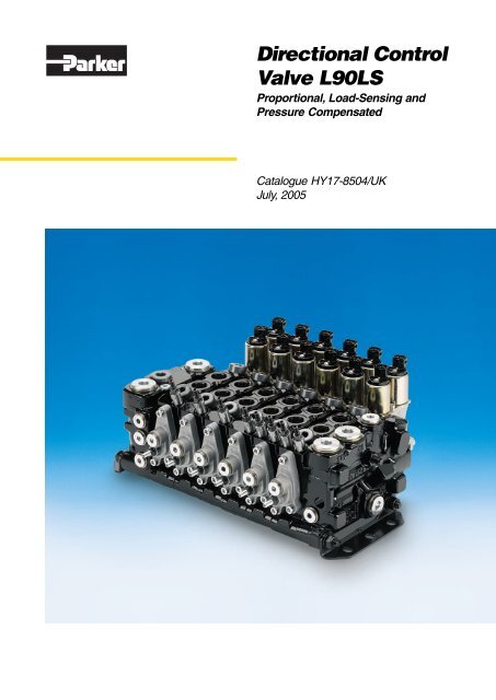
<strong>Directional</strong> <strong>Control</strong><br />
<strong>Valve</strong> <strong>L90LS</strong><br />
Proportional, Load-Sensing and<br />
Pressure Compensated<br />
Catalogue HY17-8504/UK<br />
July, 2005
Catalogue HY17-8504/UK<br />
Catalogue Information<br />
Catalogue layout<br />
In addition to general information and basic technical data, this<br />
catalogue contains descriptions of the many optional functions<br />
you can specify for the <strong>L90LS</strong>, so that we may customize it to<br />
control your machine optimally.<br />
Each function area of the valve is given as a subheading, followed<br />
by a brief description. When different options are available<br />
for a function area, the subheading is followed by an item<br />
number in square brackets, e.g. Pressure relief valve [16]. This<br />
is followed by a series of coded options, e.g. PA1, PS, Y,<br />
together with a brief description of what each code represents.<br />
<strong>Directional</strong> <strong>Control</strong> <strong>Valve</strong>s<br />
<strong>L90LS</strong><br />
Alternatively, one or more pressure, flow or voltage options are<br />
given.<br />
On page 8 is a general circuit diagram, which shows the basic<br />
function areas of the <strong>L90LS</strong>, as well as the item numbers<br />
that represent them. The same item numbers are of course used<br />
in all sub-circuit diagrams elsewhere in the catalogue. Please<br />
note that, unless stated otherwise, all sections and views of the<br />
valves have been drawn as seen from the inlet section.<br />
Computer-aided valve specification<br />
We have developed a computer program to specify the <strong>L90LS</strong><br />
on the basis of the criteria for each individual machine function.<br />
The program facilitates optimal configuration of the valve for<br />
maximum performance in different applications. It also generates<br />
documentation in the form of a detailed specification and<br />
hydraulic circuit diagram for your valve, as well as a unique ID<br />
number that is stamped into the valve data plate. Your valve<br />
specifications are then stored on our database to facilitate rapid<br />
identification in the event of service enquiries or re-ordering.<br />
Early consultation with Parker saves time and money<br />
Our experienced engineers have in-depth knowledge of<br />
different types of hydraulic system and the ways in which they<br />
work. They are at your disposal to offer expert advice on the<br />
best system for the desired combination of machine functions,<br />
control characteristics and economic criterie. By consulting<br />
Parker early in the project planning stage, you are assured of a<br />
comprehensive hydraulic system that gives your machine the<br />
best possible operating and control characteristics.<br />
Parker reserves the right to modify products without prior notice.<br />
Typical curves and diagrams are used in this catalog.<br />
Even though the catalog is revised and updated continuously,<br />
there is always the possibility of errors. For more detailed information<br />
about the products, please contact Parker.<br />
Conversion factors<br />
1 kg = 2.2046 lb<br />
1 N = 0.22481 lbf<br />
1 bar = 14.504 psi<br />
1 l = 0.21997 UK gallon<br />
1 l = 0.26417 US gallon<br />
1 cm 3 = 0.061024 in 3<br />
1 m = 3.2808 feet<br />
1 mm = 0.03937 in<br />
9/5 °C + 32 = °F<br />
3 Parker Hannifin<br />
Mobile <strong>Control</strong>s Division<br />
Borås, Sweden
Catalogue HY17-8504/UK<br />
Contents<br />
<strong>Directional</strong> <strong>Control</strong> <strong>Valve</strong>s<br />
<strong>L90LS</strong><br />
List of contents<br />
Page<br />
General Information ....................................................................................................... 5<br />
Technical Data ............................................................................................................ 6-7<br />
Hydraulic circuits ........................................................................................................8-9<br />
Inlet sections [15] ........................................................................................................ 10<br />
Pressure relief valve [16] ....................................................................................... 12<br />
Pressure setting [17] ............................................................................................. 12<br />
Differential pressure limiter [18] ............................................................................ 12<br />
Load signal system [20] ........................................................................................ 13<br />
Pump-unloading function [22] ............................................................................... 14<br />
Tank connection T1 [25] ........................................................................................ 14<br />
Pump connection P1 [26] ...................................................................................... 14<br />
End section [30] ........................................................................................................... 15<br />
LS connection [31] ................................................................................................. 15<br />
Pump connection P2 [32] ...................................................................................... 15<br />
Counter pressure valve / tank connection T2 [33] ................................................ 16<br />
Tank connection T3 [34] ........................................................................................ 16<br />
Internal-pilot pressure supply [37] ......................................................................... 16<br />
Pilot filter [39] ......................................................................................................... 17<br />
Separate tank connection for pilot circuit [40] ....................................................... 17<br />
Spool Section .............................................................................................................. 18<br />
Spool actuator, enclosed variant, type ECH and PC ........................................... 18<br />
Spool actuator, open variant, type C ..................................................................... 18<br />
Basic variants of spool section [47] ...................................................................... 18<br />
Spool actuators [50] .............................................................................................. 20<br />
Directly operated, with open spool-end .......................................................... 20<br />
ON/OFF remote-controlled, with open spool-end ........................................... 21<br />
Remote-controlled, proportional spool actuators with open spool-end .......... 21<br />
Lever brackets [51] .......................................................................................... 21<br />
Directly operated with enclosed spool-ends ................................................... 22<br />
Proportionally remote-controlled, with enclosed spool-ends ................... 22-23<br />
Connector types [56] ....................................................................................... 23<br />
Lever bracket [51] ............................................................................................ 24<br />
Pilot restrictor [55 A, B] ................................................................................... 24<br />
Choice of spool ...................................................................................................... 25<br />
Spool function [60] ........................................................................................... 25<br />
Flow requirements [61 A, B] ............................................................................ 25<br />
Spool symbols ................................................................................................. 25<br />
Area ratios [62] ................................................................................................ 26<br />
Load characteristics [63] ................................................................................. 26<br />
Force feedback [64 A, B] ................................................................................. 26<br />
Pressure compensator / load-hold check valve [66] ....................................... 27<br />
Damping of pressure compensator [67] .......................................................... 27<br />
Spool designations [69] ................................................................................... 27<br />
Flow settings [72] .................................................................................................. 28<br />
Feed-reducing valve [75] ....................................................................................... 28<br />
Setting of feed reduction in the A-/B-port [75A] [75B] .......................................... 28<br />
Port relief and/or anti-cavitation valves [76 A, B] ........................................................ 29<br />
System functions ......................................................................................................... 30<br />
System signal lines [80] ........................................................................................ 30<br />
Individual LS connection [81] ................................................................................ 30<br />
Two-speed function [82] ........................................................................................ 31<br />
Internal connection of service port [85] ................................................................ 31<br />
Function manifolds [90-99] .................................................................................... 31<br />
Dimensional Drawing, Spool actuators with enclosed spool end ............................... 32<br />
Dimensional Drawing, Spool actuators with open spool end ..................................... 33<br />
Levers for open spool-actuators .................................................................................. 34<br />
Direct lever for enclosed spool-actuators .................................................................... 34<br />
[00] refer to position numbers in the customer specification.<br />
4 Parker Hannifin<br />
Mobile <strong>Control</strong>s Division<br />
Borås, Sweden
Catalogue HY17-8504/UK<br />
General Information<br />
<strong>Directional</strong> <strong>Control</strong> <strong>Valve</strong>s<br />
<strong>L90LS</strong><br />
The <strong>L90LS</strong> is a stackable, multi-section,<br />
load-sensing, pressure-compensated directional<br />
valve for mobile machines such<br />
as cranes, skylifts, forklift trucks, platform<br />
trucks, excavators and harvesters. It is<br />
designed for working pressures of up to<br />
320 bar and a maximum pump flow of<br />
150 l/min. The valve can be given excellent<br />
simultaneous-operating characteristics,<br />
which enable several machine functions<br />
to be operated responsively at the<br />
same time, regardless of the sizes of individual<br />
loads.<br />
To facilitate precise customization for<br />
different applications, the <strong>L90LS</strong> is of<br />
wholly modular construction. Each valve<br />
is therefore built to order, so that it incorporates<br />
exactly the valve functions and<br />
values needed to control the given machine<br />
in an optimal way.<br />
Compact, integral system<br />
construction<br />
The total modularity of the <strong>L90LS</strong> gives<br />
unique opportunities to integrate a wide<br />
range of normally external functions into<br />
the valve. Such functions can be common<br />
or specific to individual spool-sections, so<br />
that widely differing criteria for individual<br />
machine functions can be met in just one<br />
valve. This enables compact, tailored,<br />
logical, pre-tested, service-friendly system<br />
solutions to be created for many different<br />
types of machine.<br />
In situations where flow demands<br />
vary so greatly that two separate directional<br />
valves would normally be required,<br />
the <strong>L90LS</strong> can, with the aid of a special<br />
adapter plate, be flanged to a larger valve<br />
such as the K170LS or K220LS to give a<br />
compact, unitized system solution and<br />
optimum economy.<br />
Wide range of spool actuators<br />
The spools in the <strong>L90LS</strong> can be actuated<br />
directly by means of levers or remotely by<br />
pneumatic, electro-pneumatic, hydraulic<br />
or electro-hydraulic remote control. Some<br />
of our remote-controlled spool actuators<br />
can be fitted with a supplementary direct<br />
lever to give a dual-control and/or emergency<br />
facility. The wide range of actuating<br />
options gives the machine designer great<br />
freedom in terms of control criteria and<br />
component location.<br />
Customisation and economy<br />
The <strong>L90LS</strong> can be tailored optimally to<br />
control either simple or complex machinefunctions<br />
and combinations thereof. Its<br />
facilities for integrating total, wholly customized<br />
solutions for a wide range of applications<br />
give low system costs and minimal<br />
energy consumption.<br />
Safety and serviceability<br />
The design of the <strong>L90LS</strong> makes it easy<br />
for machine manufacturers to comply with<br />
national and international safety regulations,<br />
such as those contained in the EC<br />
Machinery Directive. Special safety functions<br />
for machines such as cranes and<br />
skylifts can be integrated into the valve in<br />
a logical and simple way. With all system<br />
functions contained in a robust, compact,<br />
pre-tested unit with minimal external<br />
pipework, overall safety and reliability is<br />
greatly improved at the same time as<br />
servicing and the training of personnel is<br />
made much easier.<br />
Spool sections and flow rates<br />
The <strong>L90LS</strong> can be supplied in combinations<br />
of 1-12 spool sections or in combination<br />
with special function manifolds fitted<br />
between spool sections. The maximum<br />
recommended flow rate per spool<br />
section is 125 l/min, or 90 l/m when<br />
equipped with a pressure compensator.<br />
Examples of optional functions<br />
Depending on the application and operating<br />
criteria of the machine, a wide range<br />
of common, section- or port-specific optional<br />
functions can be integrated into the<br />
<strong>L90LS</strong>. Examples include:<br />
• a bypass function in the inlet section<br />
for systems fed by fixed pumps<br />
• a pump-unloading function that blocks<br />
the pump inlet when activated, thus<br />
enabling an emergency-stop function<br />
to be incorporated into the system<br />
• section-specific pressure compensation<br />
• section-specific load-hold check functions<br />
• port-specific relief and anti-cavitation<br />
functions<br />
• port-specific feed reduction<br />
• port-specific force-feedback functions<br />
that enable force-sensing and also<br />
provide a hydraulic ramp function<br />
• a load-signal copying function to eliminate<br />
micro-sinking<br />
• a built-in pilot-pressure function in the<br />
end section<br />
• a counter pressure function that gives<br />
exceptionally good make-up characteristics<br />
and the possibility of unloading<br />
lowering movements<br />
• section-specific two-speed functions<br />
that enable switching between performance<br />
and precision work in machines<br />
such as cranes and skylifts<br />
• automatic stopping functions for selected<br />
machine movements in the<br />
event of overload or the reaching of<br />
other pre-determined limits<br />
• priority for machine functions such as<br />
brakes and steering.<br />
5 Parker Hannifin<br />
Mobile <strong>Control</strong>s Division<br />
Borås, Sweden
Catalogue HY17-8504/UK<br />
Technical Data<br />
<strong>Directional</strong> <strong>Control</strong> <strong>Valve</strong>s<br />
<strong>L90LS</strong><br />
Connection for hydraulic<br />
remote control, PC.<br />
Tank connection<br />
T1 [25]<br />
Service port connection, B-port.<br />
Pilot pressure supply<br />
for external use, PS.<br />
Separate tank connection<br />
for pilot circuit, TP<br />
[40]<br />
Pump connection<br />
P2 [32]<br />
Tank connection<br />
T2 [33]<br />
Tank connection<br />
T3 [34]<br />
Pump connection<br />
P1 [21]<br />
LS<br />
PX<br />
PL<br />
LS connection from parallel<br />
valve LSP [31]<br />
Service port connection, A-port.<br />
Pressures<br />
Pump inlet max. 260/320 bar* (3800/4600<br />
psi)<br />
Service ports max. 280/350 bar* (4000/5000<br />
psi)<br />
Tank connection<br />
max. 20 bar (290 psi)<br />
* Stated pressures are absolute shock pressures, valid for<br />
grey / nodular iron.<br />
Flow rates, recommended<br />
Pump connection<br />
Service port, with pressure<br />
compensator<br />
Service port, without pressure<br />
compensator<br />
Return from service port<br />
max. 200 l/min (50 US gpm)<br />
max. 90** l/min (24 US gpm)<br />
max. 125** l/min (33 US gpm)<br />
max. 150 l/min (40 US gpm)<br />
Feed reducing valves<br />
Setting range<br />
50 - 330 bar (725-4800 psi)<br />
Internal pilot pressure<br />
Fixed setting<br />
22, 35 or 43 bar (320, 508 or 625 psi)<br />
Filtration<br />
Filtration must be arranged so that Target Contamination Class<br />
20/18/14 according to ISO 4406 is not exceeded. For the pilot<br />
circuit, Target Contamination Class 18/16/13 according to ISO<br />
4406 must not be exceeded.<br />
** Depending on spool variant.<br />
6 Parker Hannifin<br />
Mobile <strong>Control</strong>s Division<br />
Borås, Sweden
Catalogue HY17-8504/UK<br />
Technical Data<br />
<strong>Directional</strong> <strong>Control</strong> <strong>Valve</strong>s<br />
<strong>L90LS</strong><br />
Temperature<br />
Oil temperature, working range<br />
+20 to 90 °C (68 to 194 °F)*<br />
Hydraulic fluids<br />
Best performance is obtained using mineral-base oil of high<br />
quality and cleanness in the hydraulic system.<br />
Hydraulic fluids of type HLP (DIN 51524), oil for automatic<br />
gearboxes Type A and engine oil type API CD can be used.<br />
Viscosity, working range<br />
15-380 mm 2 /s**<br />
Technical information in this catalogue is applicable at an<br />
oil viscosity of 30 mm 2 /s and temperature of 50 °C using<br />
nitrile rubber seals.<br />
Connections<br />
Connection In section G-version UN-version<br />
P1 inlet G 3/4 1 1/16-12 UN-2B<br />
P2 end and MU G 1/2 7/8-14 UNF-2B<br />
T1 inlet G 3/4 1 1/16-12 UN-2B<br />
T2,T3 end and MU G 3/4 1 1/16-12 UN-2B<br />
TP end and MU G 3/8 3/4-16 UNF-2B<br />
A, B spool G 1/2 7/8-14 UNF-2B<br />
LS, PL inlet G 1/4 9/16-18 UNF-2B<br />
PX inlet G 1/4 9/16-18 UNF-2B<br />
PS end and MU G 1/4 9/16-18 UNF-2B<br />
PS2 end G 1/8 7/16-20 UNF-2B<br />
PC spool G 1/4 9/16-18 UNF-2B<br />
ACP, ACE, ACEF spool G 1/8 1/8-27 NPTF<br />
LSA/B spool G 1/8 7/16-20 UNF-2B<br />
LSP end G 1/4 9/16-18 UNF-2B<br />
LSP MU – 9/16-18 UNF-2B<br />
(male)<br />
Weights<br />
Inlet section 5.5 kg 12.1 lb<br />
End section 4.2 kg 9.3 lb<br />
Combined spool-end section, MU<br />
compared to spool section below<br />
adds 1.2 kg (2.6 lb)<br />
Spool section with spool actuator:<br />
C, B3 4.1 kg 9.0 lb<br />
ACE 5.2 kg 11.5 lb<br />
CH, CHB3, CHX, PC 4.5 kg 9.9 lb<br />
PCH 4.7 kg 10.4 lb<br />
EC, ECS, 5.2 kg 11.5 lb<br />
ECH, ECHL 5.4 kg 11.9 lb<br />
* Performance efficiency will be reduced if outside the ideal<br />
values. These extreme conditions must be evaluated by the<br />
user to establish suitability of the products performance.<br />
* * Product operating limits are broadly within the above range,<br />
but satisfactory operation within the specification may not be<br />
accomplished. Leakage and response will be affected when<br />
used at temperature extremes and it is up to the user to determine<br />
acceptability at these levels.<br />
7 Parker Hannifin<br />
Mobile <strong>Control</strong>s Division<br />
Borås, Sweden
Catalogue HY17-8504/UK<br />
Hydraulic circuits<br />
<strong>Directional</strong> <strong>Control</strong> <strong>Valve</strong>s<br />
<strong>L90LS</strong><br />
B A B A<br />
T1<br />
P2B<br />
T2B<br />
P1<br />
T3B<br />
PL LS PX<br />
LSPB<br />
<strong>L90LS</strong> with levers for direct spool actuation and equipped with<br />
bypass for systems fed by pumps with fixed displacement.<br />
T1B<br />
B A B A PS<br />
TPB<br />
P2B<br />
P1<br />
T3<br />
PL PX<br />
LS<br />
LSPB<br />
<strong>L90LS</strong> with electro-hydraulic remote-controlled spool actuators<br />
and equipped with direct-acting pressure relief valve for systems<br />
fed by LS pumps, pump-unloading function, integrated pilot-oil<br />
supply, counter pressure function, section-specific pressure<br />
compensators, port-specific feed reducing valves, port-relief and<br />
anti-cavitation valves, etc.<br />
8 Parker Hannifin<br />
Mobile <strong>Control</strong>s Division<br />
Borås, Sweden
Catalogue HY17-8504/UK<br />
Hydraulic circuits<br />
<strong>Directional</strong> <strong>Control</strong> <strong>Valve</strong>s<br />
<strong>L90LS</strong><br />
50 66 76 75 50<br />
25<br />
T1<br />
B A B A<br />
PS<br />
TPB<br />
40<br />
22<br />
P2B<br />
32<br />
39<br />
20<br />
37<br />
33<br />
15, 16<br />
26<br />
P1<br />
T3<br />
34<br />
PL PX<br />
LS<br />
LSPB<br />
67<br />
60<br />
47<br />
60<br />
31<br />
Hydraulic circuit diagram showing basic functions of <strong>L90LS</strong><br />
The item numbers in the hydraulic circuit diagram and table<br />
below refer to the valve function areas for which different options<br />
are available. The valve in the example above is<br />
equipped according to the description below. For other equipment<br />
alternatives, see under respective valve-function area<br />
[Item number] in catalogue.<br />
Item<br />
No. Code Description<br />
15 CFC Inlet with bypass for systems with fixed pump.<br />
16 PS Pilot-operated main pressure relief valve.<br />
20 KB Prepared for load-signal copying.<br />
22 BEN Electrically activated pump-unloading functionthat<br />
blocks the pump and unloads the load<br />
signal.<br />
25 T1X Tank connection in the inlet open for by-pass flow.<br />
26 P1 Pump connection in inlet open.<br />
31 LSPB Load-signal connection for parallel-connected<br />
valve plugged.<br />
32 P2B Pump connection Plugged.<br />
33 MF Counter pressure valve with fixed setting.<br />
34 T3 Tank connection open.<br />
37 R Pressure reducing valve with separate safety valve<br />
for internal pilot pressure supply.<br />
39 S Internal coarse filter for pilot circuit.<br />
40 TPB Prepared for separate tank connection from pilot<br />
circuit.<br />
Item<br />
No. Code Description<br />
47 TTT Section 1 equipped with pressure compensator,<br />
separate feed reducers for A- and B-ports, and<br />
prepared for port relief valves in both service<br />
ports.<br />
000 Section 2 without pressure compensator, feed reducer<br />
or port relief valve.<br />
50 EC Section 1 equipped with proportional electrohydraulic<br />
remote control.<br />
CH Section 2 equipped for direct operation with spring<br />
centring.<br />
60 D Sections 1 and 2 equipped with spool for doubleacting<br />
function, with service ports blocked in<br />
neutral position.<br />
66 K Pressure compensator with built-in check valve<br />
function.<br />
67 0.8 Restriction of load signal to pressure compensator.<br />
75 Pressure setting for feed reducers in A- and B-<br />
ports.<br />
76A N2 Anti-cavitation valve in A-port.<br />
76B<br />
Pressure setting for combined port-relief and anticavitation<br />
valve in B-port.<br />
9 Parker Hannifin<br />
Mobile <strong>Control</strong>s Division<br />
Borås, Sweden
Catalogue HY17-8504/UK<br />
Inlet Section<br />
<strong>Directional</strong> <strong>Control</strong> <strong>Valve</strong>s<br />
<strong>L90LS</strong><br />
Pump connection P1 [26] Tank connection T1 [25]<br />
Pressure relief valve [16]<br />
Gauge port:<br />
Inlet section for fixed or<br />
variable pump [15]<br />
Copied load<br />
signal LS<br />
Pump pressure PX<br />
Load signal PL<br />
Pump unloading function [22]<br />
Inlet sections [15]<br />
CFC<br />
LS1<br />
LS2<br />
AS<br />
AS2<br />
IP<br />
CA/CL<br />
Inlet section for systems with fixed pump. The section is<br />
equipped with an adjustable, pilot-operated pressure<br />
relief valve [16], which protects the pump and inlet side<br />
of the valve. A built-in bypass diverts excess oil directly<br />
to tank. The bypass pressure level is controlled by the<br />
load signal, and is approx. 10 bar above the actual<br />
load-signal pressure.<br />
Inlet section for systems with LS pump. Equipped with<br />
an adjustable, pilot-operated pressure relief valve [16],<br />
which protects the pump and inlet side of the valve.<br />
Inlet section for systems with LS pump. Equipped with a<br />
non-adjustable, direct-acting pressure relief valve [16],<br />
which protects the pump and inlet side of the valve. The<br />
LS2 variant is normally equipped with a copy function<br />
for the load signal, KS [20].<br />
Inlet section for flow-sharing valve. First valve, nearest<br />
pump, in multi valve system. Sending LS-signal to<br />
pump.<br />
Secondary valve in flow-sharing sytem, sends LSsignal<br />
to first valve.<br />
Inlet plate without functions. Contains only connections<br />
for pump, load signal and a gauge port for measuring<br />
tank pressure.<br />
Combi inlet used as mid-inlet when L90 and K170/K220<br />
are assembled together. This works as an adapter<br />
plate between valves and replaces inlet sections from<br />
both valves. Combi has the same functionallity as K-<br />
series inlets including flow sharing possibilities (AS).<br />
The internal functions are specified in K-series specification.<br />
The inlet section is available in several basic variants; one for fixed<br />
pumps, two for systems with variable pumps and a simple plate<br />
for use when none of the inlet section’s integrated functions is<br />
required. Inlet sections are equipped with pump and tank connections,<br />
a connection for the load signal to LS pumps and<br />
gauge ports for measuring the pump and load-signal pressures.<br />
In all basic variants, the pump connection P1 [26] and tank connection<br />
T1 [25] are open, while the other connections are<br />
plugged. The variant for fixed pumps can be converted easily in<br />
the field to work with variable pumps, and vice versa. (CFC «<br />
LS1).<br />
Functions for maximum pressure relief, copying of the load<br />
signal and pump unloading (which blocks the hydraulic energy<br />
supply to the valve) can be integrated into the inlet section.<br />
∆p (bar)<br />
q (l/min)<br />
CFC – Idling (no load) pressure drop over bypass. P1 –T1.<br />
10 Parker Hannifin<br />
Mobile <strong>Control</strong>s Division<br />
Borås, Sweden
Catalogue HY17-8504/UK<br />
Inlet Section<br />
<strong>Directional</strong> <strong>Control</strong> <strong>Valve</strong>s<br />
<strong>L90LS</strong><br />
T1<br />
T1<br />
T1<br />
P1<br />
PL<br />
LS<br />
P1<br />
PL<br />
LS<br />
P1<br />
PL LS<br />
PX<br />
LS1<br />
– Inlet section for systems with LS pump.<br />
LS2 – Inlet section for<br />
systems with LS pump.<br />
CFC – Inlet section<br />
for systems with fixed<br />
pump.<br />
P1<br />
T1<br />
T1<br />
P1<br />
PL2 PL LS<br />
PL2<br />
PL LS<br />
AS<br />
– Inlet section for flow-sharing valve<br />
AS2<br />
– Inlet section for secondary valve in flow-sharing sytem<br />
11 Parker Hannifin<br />
Mobile <strong>Control</strong>s Division<br />
Borås, Sweden
Catalogue HY17-8504/UK<br />
Inlet Section<br />
Pressure relief valve [16]<br />
The inlet section is normally equipped with a pressure relief<br />
valve to protect the pump and valve from pressure peaks in the<br />
system when there are rapid changes in the load pressure.<br />
PA1 Direct-acting pressure relief valve, PLC183, with very<br />
fast opening sequence and good pressure characteristic.<br />
The interchangeable PLC cartridge is factory set.<br />
The cartridge has a make-up function, which means<br />
that oil is able to flow from the tank gallery to the pump<br />
gallery in the event of negative pressure in the pump<br />
circuit. The valve is intended for the LS2 inlet section [15].<br />
For setting values, please see Pressure setting [17].<br />
PLM<br />
PS<br />
Y<br />
Main relief valve in AS / AS2 inlet section. Limits the<br />
LS-signal pressure that is sent to the LS-pump.<br />
Pilot-operated pressure relief valve with fast opening<br />
sequence and very low pressure override, which effectively<br />
prevents overloading of the hydraulic pump and<br />
the machine. The valve is adjustable and is delivered<br />
factory-set according to the value specified. The valve<br />
is intended for the CFC and LS1 inlet sections [15].<br />
Picture, see page 10.<br />
Plug which can replace the pressure relief valve in the<br />
LS2 inlet section [15]. The Y-plug blocks the connection<br />
between the pump and tank completely.<br />
<strong>Directional</strong> <strong>Control</strong> <strong>Valve</strong>s<br />
<strong>L90LS</strong><br />
PA1 - Direct-acting pressure relief valve.<br />
Pressure setting [17]<br />
Pressure setting for PA1 [16]<br />
The PA1 direct-acting pressure relief valve is delivered<br />
with a fixed setting. The following standard settings are<br />
available:<br />
Pressure setting in bar: 63, 80, 100, 125, 140, 160,<br />
175, 190, 210, 230, 240, 250, 260, 280, 300 and 330.<br />
Diagram, see page 13.<br />
Pressure setting for PS [16]<br />
The PS pilot-operated pressure relief valve is adjustable<br />
from 50 to 320 bar. The valve can, however, be<br />
delivered with a fixed setting according to the value<br />
specified. Diagram, see page 13.<br />
Differential pressure limiter [18]<br />
PLS<br />
Relief function for maximising ∆p in flow-sharing systems<br />
(AS) [15].<br />
Must be set higher than the ∆p regulator in the pump.<br />
PLS - Relief funktion for maximising ∆p in flow-sharing systems.<br />
12 Parker Hannifin<br />
Mobile <strong>Control</strong>s Division<br />
Borås, Sweden
Catalogue HY17-8504/UK<br />
Inlet Section<br />
<strong>Directional</strong> <strong>Control</strong> <strong>Valve</strong>s<br />
<strong>L90LS</strong><br />
∆p (bar)<br />
400<br />
Pressure relief characteristics<br />
∆p (bar)<br />
Pressure relief characteristic<br />
300<br />
200<br />
100<br />
0<br />
0<br />
50 100 150 200<br />
q (l/min)<br />
PA1 - Direct acting pressure relief valve.<br />
PS - Pilot-operated pressure relief valve.<br />
q (l/min)<br />
Load signal system [20]<br />
The load-signal system consists of a series of shuttle valves,<br />
one for each spool section in the directional valve. The shuttle<br />
valves compare the load signals from all actuated spool sections<br />
and transmit the signal with the highest value to the PL<br />
connection in the inlet section. If the valve has a load-signal<br />
copying function, the signal is transmitted to a copy spool, which<br />
makes a copy of the signal and transmits it to the LS port.<br />
If the load-signal chain is extended to a parallel-connected<br />
valve via the LSP port [31], then the highest load signal from the<br />
parallel-connected valve is included in the comparisons made<br />
by the load-signal chain in the first valve.<br />
In the case of the CFC variant of the <strong>L90LS</strong>, i.e. the variant<br />
fed by a fixed pump, the highest load signal is transmitted to the<br />
bypass valve, which regulates the pressure in the pressure gallery<br />
to approx. 10 bar above the value of the signal.<br />
KB<br />
Inlet section machined for copy spool but blocked.<br />
Provides option to install copy spool later.<br />
The load signal goes directly to the bypass in CFC<br />
systems, or to the PL connection in LS systems.<br />
KS Inlet section with copy spool.<br />
The load signal acts on a copy spool, which sends a<br />
copied load signal to the LS connection.<br />
The copying system permits a certain consumption<br />
in the load-signal line to the pumpregulator, without the<br />
load signal being influenced. This enables simpler system<br />
construction, with the possibility of installing logic<br />
systems in the LS circuit. Thanks to drainage in the<br />
pump LS regulator, the system gives better winter operating<br />
characteristics with faster response, since the<br />
oil in the LS circuit is always warm. Moreover, it prevents<br />
the tendency for the load to sink slightly at the<br />
beginning of the lifting phase.<br />
Inlet sections of type LS2 [15] are normally equipped<br />
with copy spools.<br />
/ Not machined for copy spool.<br />
Load signal from<br />
spool section<br />
KB - Inlet section without copy spool.<br />
KS - Inlet section with copy spool.<br />
Load signal to bypass<br />
or pump regulator<br />
Copied load signal to<br />
pump regulator<br />
Pump<br />
Load signal from<br />
spool section<br />
13 Parker Hannifin<br />
Mobile <strong>Control</strong>s Division<br />
Borås, Sweden
Catalogue HY17-8504/UK<br />
Inlet Section<br />
Pump-unloading function [22]<br />
If required, the valve can be equipped with a pump-unloading<br />
function in the inlet section. This enables machine manufacturers<br />
to equip their machines with an emergency-stop function to<br />
comply with the EC Machinery Directive. The function can be<br />
controlled either electrically or hydraulically.<br />
(The inlet section is not normally machined to accommodate<br />
the pump-unloading function.)<br />
BEN<br />
BX<br />
Electrically controlled pump-unloading function. When<br />
the current to the electromagnet is broken, the pump is<br />
blocked and the load signal drained to tank. In both LS<br />
and CFC systems, this means that the pressure gallery<br />
is shut off from the pump inlet and the pump is unloaded.<br />
Hydraulically controlled pump-unloading function.<br />
When an external hydraulic signal with the same pressure<br />
as the pump is connected to the BX port, the<br />
pump is blocked and the load signal drained to tank. In<br />
both LS and CFC systems, this means that the pressure<br />
gallery is shut off from the pump inlet and the<br />
pump is unloaded.<br />
Connection: G1/2 or 9/16-18 UNF-2B.<br />
Tank connection T1 [25]<br />
T1<br />
T1B<br />
T1X<br />
Tank connection T1 is open. Normal variant.<br />
Tank connection T1 is blocked.<br />
Used together with CFC [15] and MF counter pressure<br />
functions [33] only. Tank connection T1 in the inlet section<br />
is separated from the tank galleries in the spool<br />
sections. Pump oil that is not used flows via the bypass<br />
directly to tank via T1, while returning oil from the actuators<br />
flows to tank via the counter pressure valve in<br />
the end section and tank connection T3.<br />
Circuit, see page 9.<br />
Pump connection P1 [26]<br />
P1<br />
P1B<br />
Pump connection P1 is open. Normal variant.<br />
Pump connection P1 is plugged.<br />
<strong>Directional</strong> <strong>Control</strong> <strong>Valve</strong>s<br />
<strong>L90LS</strong><br />
BEN - Electrically controlled pump-unloading function.<br />
External connection of signal<br />
pressure from pump line<br />
BX - Hydraulically controlled pump-unloading function.<br />
BX – Connection of signal pressure.<br />
14 Parker Hannifin<br />
Mobile <strong>Control</strong>s Division<br />
Borås, Sweden
Catalogue HY17-8504/UK<br />
End Section<br />
<strong>Directional</strong> <strong>Control</strong> <strong>Valve</strong>s<br />
<strong>L90LS</strong><br />
Counter pressure valve,<br />
MF (tank connection),<br />
T2 [33]<br />
Tank connection, T3 [34]<br />
Separate tank connection<br />
for pilot circuit, TP [40]<br />
Pilot pressure<br />
connection, PS<br />
Pilot filter, S [39]<br />
Internal pilot pressure<br />
supply, R [37]<br />
LS-connection,<br />
LSP [31]<br />
Pump connection, P2 [32]<br />
The end section can be equipped with a number of optional<br />
functions to customize it optimally for the given application. It<br />
can, for instance, be equipped with a pressure-reducing valve to<br />
supply internal pilot-pressure for hydraulic or electro-hydraulic<br />
spool actuators, and a fixed counter pressure valve in the T2<br />
port.<br />
End section [30]<br />
For combination possibilities with series K-valve.<br />
See inlet section page 10.<br />
US Standard end-section<br />
MU<br />
Combined spool and end section (one casting), without<br />
MF and R options.<br />
LS connection [31]<br />
LSP<br />
LSPB<br />
Port for connection of LS signal from other valve open.<br />
This connection is used to receive the load signal from<br />
a parallel-connected valve.<br />
Port for LS signal from other valve plugged.<br />
In the basic version of the end section, all connections are<br />
plugged.<br />
As an alternative to the standard end-section, when internal<br />
pilot generation and counter pressure valves are not needed, a<br />
combined spool-end section (MU) can be selected. MU, together<br />
with the combi-inlet section (CL/CA [15] see page 10), makes a<br />
very compact and cost effective solution.<br />
T<br />
P<br />
P2B<br />
Pump connection P2 [32]<br />
P2<br />
P2B<br />
Alternative pump connection in rear face. The connection<br />
can, for example, be used to feed valves located to<br />
the rear, or for double feeding of the valve in applications<br />
where many machine functions with very high flow<br />
demands are operated simultaneously. Under certain<br />
provisions, the connection can also be used in situations<br />
when feeding from the rear face is the most suitable<br />
option in terms of available space. When feeding<br />
via P2, the pump-unloading function [22] cannot be<br />
used.<br />
Alternative pump connection plugged.<br />
LS<br />
T<br />
LSPB<br />
LSPB - LSP-port plugged<br />
and LS-signal line internally<br />
connected to tank.<br />
T2B<br />
T3B<br />
LS<br />
T<br />
LSP<br />
T2B<br />
T3B<br />
LSP – Port for connection of<br />
LS signal from other valve is<br />
open.<br />
15 Parker Hannifin<br />
Mobile <strong>Control</strong>s Division<br />
Borås, Sweden
Catalogue HY17-8504/UK<br />
End Section<br />
<strong>Directional</strong> <strong>Control</strong> <strong>Valve</strong>s<br />
<strong>L90LS</strong><br />
Counter pressure valve / tank connection T2 [33]<br />
T<br />
T2<br />
Alternative tank connection T2 open.<br />
T2B<br />
MF<br />
Alternative tank connection T2 plugged.<br />
Counter pressure valve factory set to give 5 bar counter<br />
pressure. Tank connection T1 must be plugged (T1B)<br />
[25] and tank connection T3 [34] must be open.<br />
If the system has a fixed pump, CFC [15], the separate<br />
tank line T1X [25] from the bypass can be used to<br />
reduce the idling (no load) losses in the system.<br />
Tank connection T3 [34]<br />
T3<br />
T3B<br />
Tank connection T3 is open.<br />
Tank connection T3 is plugged.<br />
T<br />
P<br />
LS<br />
T<br />
LSPB<br />
P2B<br />
T3B<br />
T2<br />
LS<br />
T<br />
LSPB<br />
T3<br />
Internal-pilot pressure supply [37]<br />
R<br />
Internal pilot-pressure supply is a valve function, built<br />
into the end section, which works as both a pressure<br />
regulator and a pressure relief valve in the pilot circuit.<br />
For safety reasons, the R-cartridge has also been<br />
equipped with a separate safety-valve function that prevents<br />
the maximum permissible reduced pressure from<br />
being exceeded. A check valve prevents pilot oil from<br />
leaking back to the pump, and therefore enables the<br />
pressure in the pilot circuit to be maintained in the<br />
event of a temporary fall in pump pressure, e.g. during<br />
a rapid lowering movement.<br />
Pilot pressure for external use, e.g. for delivery to<br />
PCL4 remote control valves, can be tapped from the<br />
PS connection on the B-side of the end section. Pressure<br />
setting: 35 bar.<br />
T2 – Without counterpressure<br />
valve.<br />
MF – Factory-set<br />
counter pressure valve.<br />
R22<br />
Same as R, but with 22 bar pressure setting.<br />
R43<br />
Same as R, but with 43 bar pressure setting.<br />
16 Parker Hannifin<br />
Mobile <strong>Control</strong>s Division<br />
Borås, Sweden
Catalogue HY17-8504/UK<br />
End Section<br />
Pilot filter [39]<br />
S<br />
YS<br />
Coarse filter with bypass function in the internal pilot<br />
pressure supply. The filter protects the pilot circuit from<br />
dirt, especially during start-up of the system.<br />
Adapter for connection of external filter for pilot oil. Enables<br />
the pilot circuit to be supplied with cleaner oil compared<br />
with the rest of the system.<br />
Separate tank connection for pilot circuit [40]<br />
This connection is machined into the end section only when the<br />
valve is furnished with internal pilot-pressure supply [37].<br />
TP<br />
TPB<br />
TPX<br />
Separate tank connection for the pilot circuit is open.<br />
The connection to the main tank gallery of the directional<br />
valve is blocked. The function is intended for systems<br />
in which there is a risk of dynamic pressure fluctuations<br />
in the tank line, which cause fluctuations in the<br />
pilot circuit when there is a common tank line.<br />
The end section is machined to provide a separate tank<br />
connection for the pilot circuit, and plugged. The tank<br />
return of the pilot circuit is connected to the tank gallery<br />
of the directional valve.<br />
Only for MU. Section is machined to provide external<br />
connection of pilot tank. There is no internal tank connections<br />
in MU. If needed then it must be arranged in<br />
the inlet manifold or externally<br />
<strong>Directional</strong> <strong>Control</strong> <strong>Valve</strong>s<br />
<strong>L90LS</strong><br />
T<br />
PS<br />
T<br />
P<br />
LS<br />
T<br />
LSPB<br />
PS<br />
TPB<br />
P2B<br />
T3B<br />
T2<br />
R - internal pilot-pressure supply.<br />
S - coarse filter with bypass function.<br />
TPB - end section machined to accommodate<br />
separate tank connection for pilot<br />
circuit, and plugged.<br />
S<br />
R<br />
T<br />
PS<br />
YS<br />
PS<br />
TPB<br />
T<br />
P<br />
P2B<br />
R<br />
LS<br />
T<br />
T3B<br />
T2<br />
LSPB<br />
R - internal pilot-pressure supply.<br />
YS - adapter for connection of external<br />
pilot-pressure filter.<br />
TPB - end section machined to accommodate<br />
separate tank connection for pilot<br />
circuit, and plugged.<br />
17 Parker Hannifin<br />
Mobile <strong>Control</strong>s Division<br />
Borås, Sweden
Catalogue HY17-8504/UK<br />
Spool Section<br />
<strong>Directional</strong> <strong>Control</strong> <strong>Valve</strong>s<br />
<strong>L90LS</strong><br />
The <strong>L90LS</strong> is stackable and can be supplied in combinations of<br />
1-12 spool sections. Each section can be equipped individually<br />
with a variety of optional functions, as well as different types of<br />
spool and spool-actuator. This enables optimum customization<br />
to the application and particular machine function in question.<br />
Spool actuator, enclosed variant, type ECH<br />
Pressure setting, feed<br />
reducing valve [75]<br />
Port relief and/or anticavitation<br />
function [76]<br />
Flow setting [72]<br />
Pilot restriction [55]<br />
Spool function [60]<br />
Spool designation [69]<br />
Damping of pressure<br />
compensator [67]<br />
Pressure compensator [66]<br />
Spool actuator, enclosed variant, type PC<br />
Flow requirement [61]<br />
Spool actuator [50]<br />
Spool actuator [50]<br />
System signal line [80]<br />
Flow-sharing compensator [66]<br />
Spool actuator, open variant, type C<br />
Basic variant [47]<br />
Lever bracket [51]<br />
18 Parker Hannifin<br />
Mobile <strong>Control</strong>s Division<br />
Borås, Sweden
Catalogue HY17-8504/UK<br />
Spool Section<br />
<strong>Directional</strong> <strong>Control</strong> <strong>Valve</strong>s<br />
<strong>L90LS</strong><br />
Basic variants of spool section [47]<br />
Spool sections are available in different variants depending on<br />
the choice of optional functions:<br />
B<br />
A<br />
B<br />
A<br />
000 Not machined for pressure compensator, load-hold<br />
check valve, feed reducer, port-relief or anti-cavitation<br />
valves.<br />
V00<br />
Section fitted with load-hold check valve, but not machined<br />
for port relief valves.<br />
T<br />
P<br />
T<br />
P<br />
T00<br />
Section fitted with pressure compensator, but not machined<br />
for port relief valves.<br />
TA0<br />
TC0<br />
Section fitted with pressure compensator and feed reduction<br />
in A-port, but not machined for port relief<br />
valves.<br />
Section fitted with pressure compensator and common<br />
feed reduction in A- and B-ports, but not machined for<br />
port relief valves.<br />
LS<br />
T<br />
LS<br />
T<br />
TT0<br />
Section fitted with pressure compensator and individual<br />
feed reduction in A- and B-ports, but not machined for<br />
port relief valves.<br />
Variant 000<br />
Variant V00<br />
**T<br />
MU<br />
All of the section variants above are available in versions<br />
that are machined for, and can be fitted with, port<br />
relief and/or anti-cavitation valves in service ports A<br />
and B. In such cases, the letter T is given in the third<br />
position in the product designation, e.g. 00T, V0T, T0T,<br />
TAT, TCT and TTT. For further information, see Port relief<br />
and/or anti-cavitation valves [76].<br />
Combined spool and end section. Shorter total valve<br />
length.<br />
T<br />
P<br />
B<br />
A<br />
T<br />
P<br />
B<br />
A<br />
V** and T** have the same machining and can be converted<br />
easily from one variant to another at any time. However, the machining<br />
for *0*, *A*, *C* and *T* sections are different.<br />
For further information, see also “Pressure compensator /<br />
load-hold check valve [66]” and “Feed reducing valve [75]”.<br />
LS<br />
T<br />
LS<br />
T<br />
Variant T00<br />
Variant TA0<br />
T<br />
B<br />
A<br />
Variant **T prepared for port-relief and/or anti-cavitation valves<br />
in service-ports A and B.<br />
Above left: section with Y-plug in A-port and combined port-relief<br />
and anti-cavitation valve in B-port.<br />
Above right: section with combined port-relief and anti-cavitation<br />
valves in both A and B ports.<br />
T<br />
B<br />
A<br />
T<br />
P<br />
LS<br />
T<br />
Variant TC0<br />
B<br />
A<br />
B A<br />
T<br />
P<br />
Variant TT0<br />
19 Parker Hannifin<br />
Mobile <strong>Control</strong>s Division<br />
Borås, Sweden
Catalogue HY17-8504/UK<br />
Spoolactuators<br />
<strong>Directional</strong> <strong>Control</strong> <strong>Valve</strong>s<br />
<strong>L90LS</strong><br />
Spool actuators of both the open and enclosed type can be used<br />
on the <strong>L90LS</strong>. Open spool-actuators, in which the spool-end is<br />
exposed, are simpler and cheaper. They are intended for use in<br />
systems where low capital cost is a priority. They can be operated<br />
directly by means of linear levers or mechanical coordinate<br />
levers (joysticks), or can be connected to remote controls by<br />
means of wires.<br />
With enclosed spool-actuators, the spool-ends are totally enclosed<br />
in oil-filled caps. Enclosed spool actuators are intended<br />
primarily for hydraulic and electro-hydraulic remote control, but<br />
can also be the preferred choice for direct control in aggressive<br />
environments.<br />
Many different versions of spool actuator are available.<br />
Details can be found on pages 20-23.<br />
C<br />
Spool actuators [50]<br />
Directly operated, with open spool-end<br />
C<br />
C<br />
Spring-centred spool actuator<br />
Steplessly operable with<br />
spring-return to neutral.<br />
LM<br />
B3<br />
Spring force in neutral:<br />
Spring force when fully actuated:<br />
Three-position spool actuator<br />
Equipped with 3-position mechanical<br />
detent that gives 3 fixed positions:<br />
neutral and fully actuated in either<br />
direction. Spool remains in selected<br />
position and must be moved<br />
deliberately from one position<br />
to another.<br />
60 N<br />
130 N<br />
LU<br />
B3<br />
B3<br />
Force needed on spool to<br />
overcome detent: approx.<br />
160 N<br />
FD<br />
FD<br />
Friction-detented spool actuator<br />
Lever remains at selected stepless<br />
position. A force index indicates<br />
when the lever is in neutral.<br />
FD<br />
20 Parker Hannifin<br />
Mobile <strong>Control</strong>s Division<br />
Borås, Sweden
D101727<br />
D101727<br />
Catalogue HY17-8504/UK<br />
Spoolactuators<br />
ON/OFF remote-controlled, with open spool-end<br />
ACE<br />
Electro-pneumatic spool actuator, ON/OFF<br />
Spring-centred. Can be fitted with<br />
supplementary local lever<br />
(optional) for direct, stepless<br />
actuation of spool.<br />
<strong>Control</strong> pressure: min. 4 bar<br />
max. 10 bar<br />
Spring force in neutral:<br />
95 N<br />
Spring force when spool<br />
fully actuated:<br />
Solenoid:<br />
Voltage tolerance: ±20%<br />
Connections: G 1/8 or NPTF 1/8-27<br />
160 N<br />
12 V DC 0.85 A<br />
24 V DC 0.42 A<br />
<strong>Directional</strong> <strong>Control</strong> <strong>Valve</strong>s<br />
<strong>L90LS</strong><br />
ACE<br />
ACEF<br />
Electro-pneumatic spool actuator, ON/OFF<br />
Identical to the ACE, except that it<br />
has a common pressure gallery for<br />
primary air. The primary air can be<br />
connected to either the first or the<br />
last of the adjacent spool-sections<br />
equipped with ACEF actuators.<br />
Connection thread: G 1/8 or NPTF 1/8-27<br />
LM<br />
ACEF<br />
Remote-controlled, proportional spool actuators with<br />
open spool-end<br />
ACP Pneumatic proportional spool-actuator<br />
Can be fitted with supplementary<br />
local lever (optional) for direct,<br />
stepless actuation of spool.<br />
The ACP is best controlled by<br />
means of our VP04 remote-control<br />
valve (see separate brochure).<br />
Breakaway pressure*:<br />
2 bar<br />
Final pressure*:<br />
5.5 bar<br />
max. 10 bar<br />
Connection thread: G 1/8 or NPTF 1/8-27<br />
LU<br />
ACP<br />
Lever brackets [51]<br />
LM<br />
LU<br />
For spool actuators with open spool-end<br />
Spool-sealing cover without lever bracket for<br />
spool actuators with open spool-end<br />
*<br />
The breakaway pressure is the pressure needed for the directional<br />
valve to open the connection “pump to service port”. The<br />
final pressure is the lowest pressure needed to effect full actuation<br />
of a spool in the directional valve. This data must be taken<br />
into consideration when choosing control units, since the opening<br />
pressure of the control unit must be lower than the breakaway<br />
pressure of the spool actuator in order to avoid jerky starting<br />
and stopping. However, the control unit’s final pressure must<br />
be higher than the final pressure of the directional valve in order<br />
to ensure that the spools can be fully actuated.<br />
21 Parker Hannifin<br />
Mobile <strong>Control</strong>s Division<br />
Borås, Sweden
Catalogue HY17-8504/UK<br />
Spoolactuators<br />
Directly operated with enclosed spool-ends<br />
CH<br />
CHX<br />
CHB3<br />
Spring-centred spool actuator<br />
Has enclosed spool-ends for use in<br />
aggressive environments.<br />
Steplessly operable with spring-return<br />
to neutral.<br />
Spring force in neutral:<br />
Spring force with spool fully actuated:<br />
Spring-centred spool actuator<br />
Same as CH, but with stronger springs<br />
to compensate for friction in external<br />
linkage arms etc.<br />
Spring force in neutral:<br />
Spring force with spool fully actuated:<br />
Three-position spool actuator<br />
Equipped with 3-position mechanical<br />
detent that gives 3 fixed positions:<br />
neutral and fully actuated in either<br />
direction. Spool remains in selected<br />
position and must be moved deliberately<br />
from one position to another.<br />
Force needed on spool to<br />
overcome detent:<br />
70 N<br />
140 N<br />
85 N<br />
250 N<br />
approx. 160 N<br />
<strong>Directional</strong> <strong>Control</strong> <strong>Valve</strong>s<br />
<strong>L90LS</strong><br />
Proportionally remote-controlled, with enclosed<br />
spool-ends<br />
PC<br />
PCH<br />
* See page 21.<br />
Hydraulic spool-actuator<br />
Hydraulic spool-actuator with facility for supplementary<br />
local lever for direct control<br />
The PC and PCH are proportional, hydraulically controlled<br />
spool actuators with spring-centring to neutral.<br />
They are intended to be controlled by the PCL4 remote-control<br />
valve. When determining a suitable control<br />
pressure for the PCL4, bear in mind that its breakaway<br />
pressure should be approx. 1 bar lower than that of the<br />
directional valve in order to ensure gentle starting and<br />
stopping. The pilot pressure for the PCL4 can be<br />
tapped from the internal pilot-pressure supply in the<br />
end section of the directional valve, via the PS connection.<br />
<strong>Control</strong> pressure, breakaway*:<br />
5.5 bar<br />
<strong>Control</strong> pressure, final*:<br />
15.0 bar<br />
Permissible pressure in pilot cap: max. 35 bar<br />
Connections: G ¼ or 9/16-18 UNF<br />
See also separate catalogue for PCL4.<br />
Stroke length<br />
limitation<br />
P-B, A-T Qset B<br />
CH, CHX<br />
CHB3<br />
CH, CHX<br />
CH, CHX<br />
Stroke length<br />
limitation<br />
P-A, B-T Qset A<br />
CHB3<br />
PC<br />
PC<br />
PCH<br />
Stroke length<br />
limitation<br />
P-A, B-T Qset A<br />
PC, PCH<br />
<strong>Control</strong> signal<br />
P-A, B-T<br />
PCH<br />
Stroke length<br />
limitation<br />
P-B, A-T<br />
Stroke length<br />
limitation<br />
P-B, A-T Qset B<br />
<strong>Control</strong> signal<br />
P-B, A-T<br />
Stroke length<br />
limitation<br />
P-A, B-T Qset A<br />
22 Parker Hannifin<br />
Mobile <strong>Control</strong>s Division<br />
Borås, Sweden
Catalogue HY17-8504/UK<br />
Spoolactuators<br />
Proportionally remote-controlled, with enclosed<br />
spool-ends<br />
EC/ECS Electro-hydraulic spool actuator<br />
The EC/ECS are proportional, electro-hydraulically<br />
controlled spool actuators with spring centering to neutral.<br />
They are intended to be controlled remotely by the<br />
IQAN or EHC35 control systems. Pilot-pressure oil for<br />
the PVC25 converter-valves is led to the spool actuators<br />
through internal ducts in the directional valve. This<br />
means that only the electric cables from the control<br />
system to the converter valve needs to be connected<br />
externally.<br />
<strong>Control</strong> current for PVC25, 12 V<br />
Breakaway*<br />
min. 550 mA<br />
Fully actuated<br />
max. 980 mA<br />
<strong>Control</strong> current for PVC25, 24V<br />
Breakaway*<br />
min. 260 mA<br />
Fully actuated<br />
max. 510 mA<br />
Measuring connections: G1/4 or 9/16-18 UNF<br />
EC as ECS but with manual over-ride and air-bleed<br />
screw.<br />
*<br />
The breakaway current refers to the current needed for the directional<br />
valve to open the connection “pump to service port”.<br />
The final current is the lowest current needed to effect full actuation<br />
of a spool in the directional valve. This data must be<br />
taken into consideration when choosing control units, since the<br />
opening current of the control unit must be lower than the<br />
breakaway current of the spool actuator in order to avoid jerky<br />
starting and stopping. However, the control unit’s final current<br />
must be higher than the final current of the directional valve in<br />
order to ensure that the spools can be fully actuated.<br />
<strong>Directional</strong> <strong>Control</strong> <strong>Valve</strong>s<br />
<strong>L90LS</strong><br />
ECH<br />
ECHL<br />
Electro-hydraulic spool actuator with facility for<br />
supplementary local lever for direct control<br />
The ECH spool actuator can be operated directly and<br />
steplessly by a supplementary local lever (optional).<br />
Spring force in neutral<br />
60 N<br />
Spring force with spool fully actuated 350 N<br />
Other data as for ECS to the left.<br />
Same as ECH, but with weaker centering spring.<br />
Suitable for use, e. g. when spool actuator is<br />
mainly intended to be operated directly.<br />
Spring force in neutral<br />
85 N<br />
Spring force with spool fully actuated 250 N<br />
<strong>Control</strong> current for PVC25, 12 V<br />
Breakaway*<br />
min. 550 mA<br />
Fully actuated<br />
max. 820 mA<br />
<strong>Control</strong> current for PVC25, 24V<br />
Breakaway*<br />
min. 260 mA<br />
Fully actuated<br />
max. 440 mA<br />
Other data as for ECH above.<br />
Connector types [56]<br />
A<br />
D<br />
Solenoid with connector for<br />
Bosch 1 928 402 404 or<br />
AMP Junior-Timer type C, 963040-3.<br />
Solenoid with male type connector<br />
type "Deutsch".<br />
EC, ECS<br />
Manual<br />
override<br />
(EC only)<br />
Actuation<br />
P-A, B-T<br />
Actuation<br />
P-B, A-T<br />
EC, ECS<br />
Stroke length<br />
limitation<br />
P-A, B-T Qset A<br />
ECH, ECHL<br />
Stroke length<br />
limitation<br />
P-B, A-T Qset B<br />
ECH, ECHL<br />
EC,<br />
ECS,<br />
ECH,<br />
ECHL<br />
Stroke length<br />
limitation<br />
P-A, B-T Qset A<br />
23 Parker Hannifin<br />
Mobile <strong>Control</strong>s Division<br />
Borås, Sweden
Catalogue HY17-8504/UK<br />
Spoolactuators<br />
<strong>Directional</strong> <strong>Control</strong> <strong>Valve</strong>s<br />
<strong>L90LS</strong><br />
Lever bracket [51]<br />
In addition to the normal lever-attachment angle, L1, the lever<br />
bracket is available in 8 other angles, designated L0 to L8 (see<br />
figure opposite). In the L4 variant, for instance, the lever is<br />
mounted parallel with the spool.<br />
L1<br />
Standard lever-bracket for directly operated spool actuators<br />
with enclosed spool-ends, e.g. CH, and for remote-controlled<br />
spool actuators that have facility for<br />
supplementary local lever for direct control, e.g. ECH.<br />
2<br />
20°<br />
3<br />
20°<br />
4<br />
20°<br />
1<br />
20°<br />
0<br />
L * = P–A B–T<br />
A<br />
B<br />
20°<br />
5<br />
20°<br />
6<br />
20°<br />
7 20°<br />
8<br />
Lever brackets L can be given different attachment angles.<br />
Pilot restrictor [55 A, B]<br />
To give gentle control characteristics, remote-controlled spool<br />
actuators with enclosed spool-ends are fitted with pilot<br />
restrictors, which can be chosen individually for each service<br />
port. The restrictor gives a kind of ramp function.<br />
Restrictors from 0.6 to 1.5 mm available.<br />
B<br />
A<br />
Pilot restrictor<br />
24 Parker Hannifin<br />
Mobile <strong>Control</strong>s Division<br />
Borås, Sweden
Catalogue HY17-8504/UK<br />
Choice of spool<br />
<strong>Directional</strong> <strong>Control</strong> <strong>Valve</strong>s<br />
<strong>L90LS</strong><br />
The spool is the most important link between the operator’s actuation<br />
of a control lever and the behaviour of the corresponding<br />
machine function. The designs of our spools are therefore customized<br />
to meet the operating criteria of each individual machine<br />
function as accurately as possible. Spools are designed<br />
with the aid of a computerized specification system, which takes<br />
all factors into account.<br />
Spool function [60]<br />
There are many spool variants: D, EA, EB, M, CA, Dm, Da and<br />
Db, which are customized for different flows, load conditions and<br />
actuator area ratios. The spools are also available with different<br />
degrees of force feedback from the A- and/or B-side.<br />
D<br />
EA<br />
EB<br />
M<br />
Double-acting spool for, e.g. double-acting cylinder.<br />
Blocked in the neutral position.<br />
Single-acting spool for, e.g. single-acting cylinder.<br />
Blocked in the neutral position. Service port B blocked.<br />
Single-acting spool for, e.g. single-acting cylinder.<br />
Blocked in the neutral position. Service port A blocked.<br />
Double-acting spool for, e.g. hydraulic motor. Float<br />
position function in neutral position.<br />
CA Regenerative spool for rapid feeding of cylinder via the<br />
A-port. The large side of the cylinder is connected to<br />
the A-port.<br />
Dm Double-acting spool with drainage A to T and B to T,<br />
which prevents pressure build-up in the neutral position.<br />
The spool is used as a double-acting spool in combination<br />
with, e.g. an overcentre valve.<br />
Da<br />
Db<br />
Double-acting spool with drainage A to T, which<br />
prevents pressure build-up in the A-port in the neutral<br />
position. The spool is used as a double-acting spool in<br />
combination with, e.g. an overcentre valve.<br />
Double-acting spool with drainage B to T, which<br />
prevents pressure build-up in the B-port in the neutral<br />
position. The spool is used as a double spool in combination<br />
with, e.g. an over-centre valve.<br />
Spool symbols<br />
D<br />
EA<br />
EB<br />
M<br />
CA<br />
Dm<br />
Da<br />
Db<br />
B A<br />
P T<br />
Flow requirements [61 A, B]<br />
There is a wide range of computer-optimized spool designs for<br />
the <strong>L90LS</strong> with nominal flows of up to 90 l/min per spool-section<br />
when the sections are equipped with individual pressure-compensators.<br />
Without individual pressure-compensators, flows up to 125 l/<br />
min per spool section are obtainable, depending on the adjusted<br />
differential between the load-signal pressure and the pump pressure.<br />
On the basis of the desired flows to the A and B ports entered<br />
in the ordering documentation, our computerized valvespecification<br />
system selects a spool to give at least the specified<br />
flow, at the same time taking all other parameters into account.<br />
The maximum flow is then set by limiting the spool stroke by<br />
means of adjustment screws on the spool actuators or, in the<br />
case of electro-hydraulic remote control, by tuning the electronics.<br />
See “Flow settings [72]” for details on factory-set maximum<br />
flows.<br />
q (l/min)<br />
Flow rate in motor connection<br />
Spool stroke (mm)<br />
Typical curves showing flow as a function of spool stroke.<br />
25 Parker Hannifin<br />
Mobile <strong>Control</strong>s Division<br />
Borås, Sweden
Catalogue HY17-8504/UK<br />
Spool Section<br />
<strong>Directional</strong> <strong>Control</strong> <strong>Valve</strong>s<br />
<strong>L90LS</strong><br />
Area ratios [62]<br />
The area ratio for a spool section is calculated by dividing the<br />
cylinder area that is connected to the B-port by the area connected<br />
to the A-port. When the large side of the cylinder is connected<br />
to the A-port, the area ratio is less than 1. The area ratio<br />
for a motor is 1.<br />
F<br />
A<br />
B<br />
Load characteristics [63]<br />
The characteristics of the lift load can be specified according to<br />
five typical cases. This information is entered so that the spool<br />
can be be customized optimally for the intended application.<br />
LAB Lift load can alternate between A-port and B-port.<br />
LA Lift load normally on A-port only.<br />
LB Lift load normally on B-port only.<br />
LN No or low lift-load on A- and B-ports.<br />
S Slewing function.<br />
PT<br />
LAB - Lift load can change between the A- and B-port.<br />
F<br />
A B<br />
PT<br />
LA - Lift load normally on A-port only.<br />
F<br />
Force feedback [64 A, B]<br />
The <strong>L90LS</strong> can be furnished with a force-feedback function to<br />
give operators of the LS system the same positive sense of<br />
force-control obtained with constant-flow (CFO) systems. This<br />
makes it easier for the operator to avoid damaging the machine<br />
in applications such as digging, since he is able to sense increasing<br />
resistance or outright obstacles to the movement of a<br />
machine function.<br />
Force feedback also gives a kind of ramp function that results<br />
in more gentle transition between rapid changes in the<br />
speed of a machine movement. This in turn has a stabilizing effect<br />
on the hydraulic system and results in smoother operation<br />
of the machine. Both characteristics are important, especially for<br />
functions like slewing movements. In addition to increasing the<br />
efficiency of the machine, they also minimize wear.<br />
The A and B ports individually can be given any one of three<br />
different levels of force feedback. The higher the level, the<br />
greater the reduction in speed for a given lever stroke as resistance<br />
rises. This means that the operator must move the lever<br />
further if he wishes to maintain the same speed of movement<br />
with rising resistance.<br />
/ No force feedback<br />
FN Normal level of force feedback<br />
FH High level of force feedback<br />
FL Low level of force feedback<br />
The force feedback function is not available for directly operated<br />
valves.<br />
A<br />
PT<br />
LB - Lift load normally on B-port only.<br />
Flow rate (%)<br />
B<br />
Force feedback<br />
Light<br />
load<br />
Heavy<br />
load<br />
Lever stroke (%)<br />
26 Parker Hannifin<br />
Mobile <strong>Control</strong>s Division<br />
Borås, Sweden
Catalogue HY17-8504/UK<br />
Spool Section<br />
Pressure compensator / load-hold check valve [66]<br />
When there are demands for very good simultaneous-operating<br />
characteristics or intensive, multi-section operability and responsiveness,<br />
individual spool-sections in the <strong>L90LS</strong> can be<br />
equipped with integral pressure-compensators. Sections so<br />
equipped are not then influenced by other simultaneously-operated<br />
machine functions, regardless of the variations in loads,<br />
provided there is sufficient pump capacity.<br />
Responding to the instantaneous value of the load signal,<br />
the pressure compensator regulates continuously the flow<br />
through the spool to maintain a constant pressure-differential<br />
between the pump and service-port sides of the spool. This results<br />
in a constant flow to the consumer for a given lever stroke,<br />
regardless of the load pressure or any activity in other spool<br />
sections.<br />
The standard variant of the pressure compensator is designated<br />
K. Three other variants, designated KL, KH and KX, which<br />
give 85, 120 and 150 % of the standard flow respectively, are<br />
also available. They are intended to enable further customization<br />
of the spool section to suit the flow requirements of the actuator.<br />
All Parker pressure compensators are fast and responsive,<br />
and come with an integrated load-hold check-valve function. If<br />
necessary, spool sections with pressure compensators can also<br />
be equipped with feed-reducing valves in the service ports to<br />
regulate the delivery pressure to the consumer to the desired<br />
level.<br />
(V** and T** spool-sections [47] have the same machining<br />
and can be converted easily to accommodate feed-reducing and<br />
port-relief valves.)<br />
/ Section not machined for pressure compensator or<br />
load-hold check valve.<br />
K Standard pressure compensator.<br />
KL<br />
KH<br />
KX<br />
KAS<br />
KAP<br />
N<br />
X<br />
Compensator that gives 85% of specified spool’s<br />
nominal flow.<br />
Compensator that gives 120% of specified spool’s<br />
nominal flow.<br />
Compensator that gives 150% of specified spool’s<br />
nominal flow.<br />
Compensator for flow-sharing systems.<br />
(consult Parker product specialist)<br />
Compensator for flow-sharing systems.<br />
(consult Parker product specialist)<br />
Section equipped with load-hold check valve.<br />
Section machined for pressure compensator or loadhold<br />
check valve, and plugged.<br />
<strong>Directional</strong> <strong>Control</strong> <strong>Valve</strong>s<br />
<strong>L90LS</strong><br />
q (l/min)<br />
Flow rate curves<br />
Load pressure (bar)<br />
Load-independent flow with pressure compensator.<br />
Damping of pressure compensator [67]<br />
The LS restrictor affects the response of the pressure compensator,<br />
and is normally chosen at 0.8 mm.<br />
/ No LS restrictor for compensator.<br />
0.6 Alternative LS restrictor for compensator.<br />
0.8 Recommended LS restrictor for compensator.<br />
1.0 Alternative LS restrictor for compensator.<br />
Spool designations [69]<br />
To facilitate optimal customization to meet the criteria of each<br />
individual machine function, the choice of spools is made with<br />
the aid of our computerized specification program. The information<br />
entered at items 60-66 forms part of the basis for the choice<br />
of spool.<br />
27 Parker Hannifin<br />
Mobile <strong>Control</strong>s Division<br />
Borås, Sweden
Catalogue HY17-8504/UK<br />
Spool Section<br />
Flow settings [72]<br />
The strokes of spools controlled by enclosed spool-actuators<br />
can be arrested to limit the maximum flow to service ports<br />
A and B.<br />
Qset<br />
QsetA<br />
QsetB<br />
The valve is supplied with factory-set maximum flows to<br />
the spool section. The settings agree with the specified<br />
flow-requirements to the A and B ports [61 A, B].<br />
The valve is supplied with factory-set maximum flow to<br />
the spool section. The setting agrees with the specified<br />
flow-requirement to the A port [61 A].<br />
The valve is supplied with factory-set maximum flow to<br />
the spool section. The setting agrees with the specified<br />
flow-requirement to the B port [61 B].<br />
When setting the flow rates for spool sections not equipped with<br />
pressure compensators in systems fed by LS pumps, the settings<br />
are made with a ∆p of 15 bar between the pump pressure<br />
at the PX port and the load signal at the PL port at full flow takeoff.<br />
(For flow setting with PC spool-actuators, please see<br />
page 22.)<br />
<strong>Directional</strong> <strong>Control</strong> <strong>Valve</strong>s<br />
<strong>L90LS</strong><br />
Setting B-port<br />
Setting A-port<br />
Limiting the maximum flow over the spool by means of mechanical<br />
stroke-length limitation of the spool stroke.<br />
Feed-reducing valve [75]<br />
The <strong>L90LS</strong> with sections designated *A*, *C* or *T* at item [47]<br />
is equipped with feed-reducing valves.<br />
Sections designated *A* have feed reduction in the A-port;<br />
those designated *C* have common feed reduction for the A-and<br />
B-ports; those designated *T* have individually adjustable feed<br />
reduction for the A-port and B-port.<br />
Feed reduction is used for system functions that require a<br />
lower maximum pressure compared with the normal working<br />
pressure of the system. The feed-reducing valve, which is steplessly<br />
adjustable from 50 to 320 bar, reduces the delivery pressure<br />
in the service port to the pre-set level.<br />
Through the use of feed-reducing valves, the delivery pressure<br />
can be limited without consuming any more than a pilot<br />
flow (
Catalogue HY17-8504/UK<br />
Spool Section<br />
Port relief and/or anti-cavitation valves [76 A, B]<br />
In spool sections designated **T [47], the PLC053 can be used<br />
as a combined port-relief and anti-cavitation valve in the service<br />
ports to protect the valve and consumer from high system pressure<br />
and pressure surges.<br />
The PLC053 is a direct-acting pressure relief valve with a<br />
very fast opening sequence and good pressure characteristic.<br />
The interchangeable PLC cartridge is factory set. The make-up<br />
function enables oil to flow from the tank gallery to the serviceport<br />
side in the event of negative pressure in the service ports, in<br />
order to prevent cavitation.<br />
/ Section not machined for port relief valves.<br />
X2 Section machined for port relief valve. Service port<br />
open to tank.<br />
Y2 Section machined for port relief valve. Connection A/B<br />
to tank blocked with plug.<br />
N2 A/B side of section equipped with anti-cavitation valve.<br />
50-350 Standard pressure settings (in bar) for port relief valves<br />
in A- or B-ports:<br />
50, 63, 80, 100, 125, 140, 160, 175, 190, 210, 230, 250,<br />
260, 280, 300, 320 and 350.<br />
<strong>Directional</strong> <strong>Control</strong> <strong>Valve</strong>s<br />
<strong>L90LS</strong><br />
Circuit diagram for PLC053 pressure relief valve.<br />
∆p (bar)<br />
Pressure relief characteristic<br />
q (l/min)<br />
∆p (bar)<br />
Make-up characteristics<br />
q (l/min)<br />
29 Parker Hannifin<br />
Mobile <strong>Control</strong>s Division<br />
Borås, Sweden
Catalogue HY17-8504/UK<br />
Spool Section<br />
<strong>Directional</strong> <strong>Control</strong> <strong>Valve</strong>s<br />
<strong>L90LS</strong><br />
System functions<br />
The <strong>L90LS</strong> can be equipped with integrated functions to create<br />
complete system solutions. The load signal from any service<br />
port or spool section can be connected with signal ducts and utilized<br />
to stop or limit the pressure to individual machine functions.<br />
In cranes, this auxiliary controlling concept is implemented<br />
with the aid of the M11 function manifold [90]. Another example<br />
of how the load-signal ducts can be exploited is in the control of<br />
thrust pressure to rock drills, according to the instantaneous rotational<br />
torque (rotation-pressure controlled thrust).<br />
T<br />
P<br />
B<br />
A<br />
Two speed line<br />
System signal lines [80]<br />
SF<br />
<strong>Valve</strong> section equipped with 3 signal lines that can be<br />
connected internally to individual load signals [81], as<br />
well as signal line for activation of two-speed function<br />
[82] .<br />
LS<br />
T<br />
LS<br />
3<br />
2<br />
1<br />
Signal lines<br />
Individual LS connection [81]<br />
/ No LS connection to signal lines. No possibility of<br />
external connection either.<br />
A1B Load signal from port A connected to duct 1.<br />
A1B2 Load signal from port A connected to duct 1.<br />
Load signal from port B connected to duct 2.<br />
A1B3 Load signal from port A connected to duct 1.<br />
Load signal from port B connected to duct 3.<br />
A2B Load signal from port A connected to duct 2.<br />
A2B2 Load signal from both ports A and B connected to<br />
duct 2.<br />
A2B3 Load signal from port A connected to duct 2.<br />
Load signal from port B connected to duct 3.<br />
AB No connection between load signal and signal ducts.<br />
AB2 Load signal from port B connected to duct 2.<br />
AB3 Load signal from port B connected to duct 3.<br />
The load signal from more than one section can be connected to<br />
the same duct. A check valve in each section prevents backward<br />
transmission of the load signal from the ducts into individual<br />
sections.<br />
In addition to connection with the signal ducts, the load signal<br />
is also available for external connection at the base of the<br />
valve.<br />
LSB LSA<br />
SF – System signal line<br />
LSB LSA LSB LSA<br />
A1B3<br />
A2B<br />
LSB LSA LSB LSA<br />
A2B2<br />
AB<br />
LSB LSA LSB LSA<br />
AB2<br />
A1B<br />
LSB LSA LSB LSA LSB LSA<br />
A1B2 A2B3 AB3<br />
30 Parker Hannifin<br />
Mobile <strong>Control</strong>s Division<br />
Borås, Sweden
Catalogue HY17-8504/UK<br />
Spool Section<br />
<strong>Directional</strong> <strong>Control</strong> <strong>Valve</strong>s<br />
<strong>L90LS</strong><br />
Two-speed function [82]<br />
Any number of spool sections in the <strong>L90LS</strong> can be furnished<br />
with a two-speed function to enable switching between performance<br />
and precision work with machines such as cranes and<br />
skylifts.<br />
The two-speed function is activated with the aid of the M11<br />
function manifold [90]. Activation reduces the flow to the consumer<br />
as indicated below:<br />
QR2 Flow to consumer reduced to 20% of normal flow.<br />
QR3 Flow to consumer reduced to 30% of normal flow.<br />
QR4 Flow to consumer reduced to 40% of normal flow.<br />
QR5 Flow to consumer reduced to 50% of normal flow.<br />
q (%)<br />
Flow<br />
Normal<br />
QR4<br />
QR2<br />
N.B.<br />
When a spool section is equipped with a two-speed function,<br />
the pressure compensator in the section does not have a loadhold<br />
check valve function. For this reason, overcentre valves<br />
might required for the controlled actuator.<br />
Diagram shows curves for:<br />
Normal flow.<br />
Flow with QR4 activated.<br />
Flow with QR2 activated.<br />
Lever stroke (%)<br />
Internal connection of service port [85]<br />
Thanks to the internal service-port connections, system solutions<br />
employing function manifolds that require the service port<br />
to be used by the manifold can be integrated without the need<br />
for external piping.<br />
A<br />
B<br />
M<br />
Gives internal service-port connection downstream of<br />
the spool section.<br />
A013<br />
Gives internal service-port connection both downstream<br />
and upstream of the spool section.<br />
M<br />
Function manifolds [90-99]<br />
The <strong>L90LS</strong> can be equipped with function manifolds that enable<br />
complete system solutions to be integrated into the valve.<br />
Standard function manifolds are available for overload protection,<br />
two-speed function, float position, priority for steering<br />
and brakes, etc. In addition to the standard units, we custombuild<br />
function manifolds to meet special system criteria. Please<br />
contact Parker for further information.<br />
Sectional manifold with internal connection of service ports to<br />
downstream function manifold.<br />
31 Parker Hannifin<br />
Mobile <strong>Control</strong>s Division<br />
Borås, Sweden
Catalogue HY17-8504/UK<br />
Dimensional Drawing<br />
<strong>Directional</strong> <strong>Control</strong> <strong>Valve</strong>s<br />
<strong>L90LS</strong><br />
Spool actuators with enclosed spool end<br />
(inch)<br />
129,5 (5.10)<br />
157,5 (6.20)<br />
90 (3.54)<br />
45 (1.77)<br />
11,5 (0.45)<br />
(1.06)<br />
27<br />
max.160 (6.30) 179 (7.05)<br />
54 (2.13) 125 (4.92)<br />
45 (1.77) 45 (1.77)<br />
(0.12)<br />
3<br />
40,5 (1.59)<br />
36 (1.42)<br />
(1.50)<br />
38<br />
(1.26)<br />
32<br />
(0.94)<br />
24<br />
CH<br />
CHX<br />
53 (2.09)<br />
43 (1.69)<br />
94 (3.70)<br />
61,4 (2.42)<br />
ECH<br />
ECHL<br />
L<br />
40 (1.57)<br />
PC<br />
35 (1.38)<br />
40 (1.57)<br />
(0.12) 3<br />
(1.75) 44,5 45 (1.77)<br />
max. 115 (4.53) max. 160 (6.30)<br />
(0.47)<br />
12<br />
67,5 (2.66)<br />
87 (3.43)<br />
(0.93) 23,5<br />
41 (1.61)<br />
With MU-section L is reduced with<br />
23 mm (0.9 inch)<br />
With IP-section L is reduced with<br />
25 mm (1 inch)<br />
Connection threads, see page 7.<br />
No. of L L<br />
sections mm inch<br />
1 169 6.65<br />
2 209 8.23<br />
3 249 9.80<br />
4 289 11.38<br />
5 329 12.95<br />
6 369 14.53<br />
7 409 16.10<br />
8 449 17.68<br />
9 489 19.25<br />
10 529 20.83<br />
11 569 22.40<br />
12 609 23.98<br />
32 Parker Hannifin<br />
Mobile <strong>Control</strong>s Division<br />
Borås, Sweden
Catalogue HY17-8504/UK<br />
Dimensional Drawing<br />
<strong>Directional</strong> <strong>Control</strong> <strong>Valve</strong>s<br />
<strong>L90LS</strong><br />
Spool actuators with open spool end<br />
(inch)<br />
57 (2.24)<br />
(0.45)<br />
11,5<br />
45 (1.77)<br />
90 (3.54)<br />
(1.06)<br />
27<br />
129,5 (5.10)<br />
165,2 (6.50)<br />
52,5 (2.07)<br />
(0.35) 9<br />
(0.14) 3,5<br />
152,5 (6.00)<br />
68 (2.68)<br />
(1.50)<br />
38<br />
(1.26)<br />
32<br />
(0.94)<br />
24<br />
61,4 (2.42)<br />
C<br />
B3<br />
ACE<br />
See page 32<br />
40 (1.57)<br />
C<br />
B3<br />
35 (1.38)<br />
40 (1.57)<br />
(1.38)<br />
35 1,5 (0.06)<br />
43 (1.69)<br />
(0.31)<br />
8 63 (2.48)<br />
(0.47)<br />
12<br />
67,5 (2.66)<br />
87 (3.43)<br />
(0.93) 23,5<br />
41 (1.61)<br />
33 Parker Hannifin<br />
Mobile <strong>Control</strong>s Division<br />
Borås, Sweden
Catalogue HY17-8504/UK<br />
Direct Levers<br />
<strong>Directional</strong> <strong>Control</strong> <strong>Valve</strong>s<br />
<strong>L90LS</strong><br />
Levers for open spool-actuators<br />
Levers M7 and M71 are made of steel with an anti-rust surface<br />
treatment, and fitted with a knob of black plastic. The knob on<br />
the M71 lever has a top window for the insertion of a symbol.<br />
The lever kits are delivered complete with pin sets for mounting<br />
to the valve.<br />
(0.98)<br />
∅25<br />
(1.06)<br />
∅27<br />
(inch)<br />
172 (6.77)<br />
207 (8.15)<br />
22 (0.87)<br />
22 (0.87)<br />
46 (1.81)<br />
53 (2.09)<br />
Lever M7<br />
Lever M71<br />
Direct lever for enclosed spool-actuators<br />
Lever for directly operated spool-actuators with enclosed spoolend,<br />
and for remote controlled spool-actuators that have a facility<br />
for a supplementary local lever for direct control.<br />
The ML1 lever is made of steel and has an anti-rust surface<br />
treatment. The lever knob is of black plastic and has a top window<br />
for the insertion of a symbol. The lever kit consists of a<br />
knob, the lever shaft and a lock nut.<br />
165 (6.50)<br />
21<br />
(0.83)<br />
Ordering number Designation<br />
9122 1780-08 M7<br />
9122 1780-11 M71<br />
8234 9390-01 ML1<br />
Lever ML1<br />
22<br />
(0.87)<br />
34 Parker Hannifin<br />
Mobile <strong>Control</strong>s Division<br />
Borås, Sweden
Catalogue HY17-8504/UK<br />
<strong>Directional</strong> <strong>Control</strong> <strong>Valve</strong>s<br />
<strong>L90LS</strong><br />
!<br />
WARNING<br />
FAILURE OR IMPROPER SELECTION OR IMPROPER USE OF THE PRODUCTS AND/OR SYSTEMS DESCRIBED<br />
HEREIN OR RELATED ITEMS CAN CAUSE DEATH, PERSONAL INJURY AND PROPERTY DAMAGE.<br />
This document and other information from Parker Hannifin Corporation, its subsidiaries and authorized distributors provide<br />
product and/or system options for further investigation by users having technical expertise. It is important that you analyze all<br />
aspects of your application, including consequences of any failure, and review the information concerning the product or<br />
system in the current product catalogue. Due to the variety of operating conditions and applications for these products or<br />
systems, the user, through its own analysis and testing, is solely responsible for making the final selection of the products and<br />
systems and assuring that all performance, safety and warning requirements of the application are met.<br />
The products described herein, including without limitation, product features, specifications, designs, availability and pricing, are<br />
subject to change by Parker Hannifin Corporation and its subsidiaries at any time without notice.<br />
Offer of Sale<br />
Please contact your Parker representation for a detailed ”Offer of Sale”.<br />
35 Parker Hannifin<br />
Mobile <strong>Control</strong>s Division<br />
Borås, Sweden
Hydraulics Group<br />
Sales Offices<br />
Europe<br />
Austria<br />
Wiener Neustadt<br />
Tel: +43 (0)2622 23501<br />
Fax: +43 (0)2622 66212<br />
Belgium<br />
Nivelles<br />
Tel: +32 (0)67 280 900<br />
Fax: +32 (0)67 280 999<br />
Czech Republic<br />
Klecany<br />
Tel: +420 284 083 111<br />
Fax: +420 284 083 112<br />
Denmark<br />
Ballerup<br />
Tel: +45 4356 0400<br />
Fax: +45 4373 8431<br />
Finland<br />
Vantaa<br />
Tel: +358 (0)9 4767 31<br />
Fax: +358 (0)9 4767 3200<br />
France<br />
Contamine-sur-Arve<br />
Tel: +33 (0)450 25 80 25<br />
Fax: +33 (0)450 03 67 37<br />
Germany<br />
Kaarst<br />
Tel: +49 (0)2131 4016 0<br />
Fax: +49 (0)2131 4016 9199<br />
Hungary<br />
Budapest<br />
Tel: +36 (06)1 220 4155<br />
Fax: +36 (06)1 422 1525<br />
Ireland<br />
Dublin<br />
Tel: +353 (0)1 293 9999<br />
Fax: +353 (0)1 293 9900<br />
Italy<br />
Corsico (MI)<br />
Tel: +39 02 45 19 21<br />
Fax: +39 02 4 47 93 40<br />
The Netherlands<br />
Oldenzaal<br />
Tel: +31 (0)541 585000<br />
Fax: +31 (0)541 585459<br />
Norway<br />
Ski<br />
Tel: +47 64 91 10 00<br />
Fax: +47 64 91 10 90<br />
Poland<br />
Warsaw<br />
Tel: +48 (0)22 863 49 42<br />
Fax: +48 (0)22 863 49 44<br />
Portugal<br />
Leca da Palmeira<br />
Tel: +351 22 9997 360<br />
Fax: +351 22 9961 527<br />
Slovakia<br />
Ref. Czech Republic<br />
Spain<br />
Madrid<br />
Tel: +34 91 675 73 00<br />
Fax: +34 91 675 77 11<br />
Sweden<br />
Spånga<br />
Tel: +46 (0)8 597 950 00<br />
Fax: +46 (0)8 597 951 10<br />
Turkey<br />
Merter/Istanbul<br />
Tel.: +90 212 482 91 06 or 07<br />
Fax: +90 212 482 91 10<br />
United Kingdom<br />
Warwick<br />
Tel: +44 (0)1926 317 878<br />
Fax: +44 (0)1926 317 855<br />
International<br />
Australia<br />
Castle Hill<br />
Tel: +61 (0)2-9634 7777<br />
Fax: +61 (0)2-9899 6184<br />
Canada<br />
Milton, Ontario<br />
Tel: +1 905-693-3000<br />
Fax: +1 905-876-0788<br />
China<br />
Beijing<br />
Tel: +86 10 6561 0520<br />
Fax: +86 10 6561 0526<br />
Asia Pacific Group<br />
Hong Kong, Kowloon<br />
Tel: +852 2428 8008<br />
Fax: +852 2425 6896<br />
India<br />
Mumbai<br />
Tel: +91 22 7907081<br />
Fax: +91 22 7907080<br />
Japan<br />
Tokyo<br />
Tel: +(81) 3 6408 3900<br />
Fax: +(81) 3 5449 7201<br />
Latin America Group<br />
Brazil<br />
Tel: +55 12 3954-5100<br />
Fax: +55 12 3954-5266<br />
South Africa<br />
Kempton Park<br />
Tel: +27 (0)11-961 0700<br />
Fax: +27 (0)11-392 7213<br />
USA<br />
Cleveland (industrial)<br />
Tel: +1 216-896-3000<br />
Fax: +1 216-896-4031<br />
Lincolnshire (mobile)<br />
Tel: +1 847-821-1500<br />
Fax: +1 847-821-7600<br />
Parker Hannifin is the world’s premier supplier of motion and control systems<br />
and solutions, with sales and manufacturing facilities throughout the world. For<br />
product information and details of your nearest Parker sales office, visit us at<br />
www.parker.com or call free on 00800 2727 5374.<br />
Catalogue HY17-8504/UK<br />
PDF 07/05<br />
© Copyright 2005<br />
Parker Hannifin Corporation<br />
All rights reserved.