PGP/PGM 620 - Oleosistemas
PGP/PGM 620 - Oleosistemas
PGP/PGM 620 - Oleosistemas

You also want an ePaper? Increase the reach of your titles
YUMPU automatically turns print PDFs into web optimized ePapers that Google loves.
zgp13
Catalog HY09-<strong>620</strong>/US<br />
General Information<br />
The Parker Hannifin<br />
Gear Pump Division<br />
Assures:<br />
! Consistent quality<br />
! Technical innovation<br />
! Premier customer service<br />
Worldwide Sales<br />
and Service<br />
Parker operates sales and service<br />
centers in major industrial areas<br />
worldwide. Call 1-800-C-PARKER for<br />
more information, or for a synopsis<br />
of the Gear Pump Division, contact a<br />
Parker representative.<br />
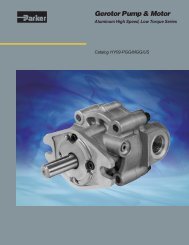
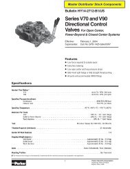
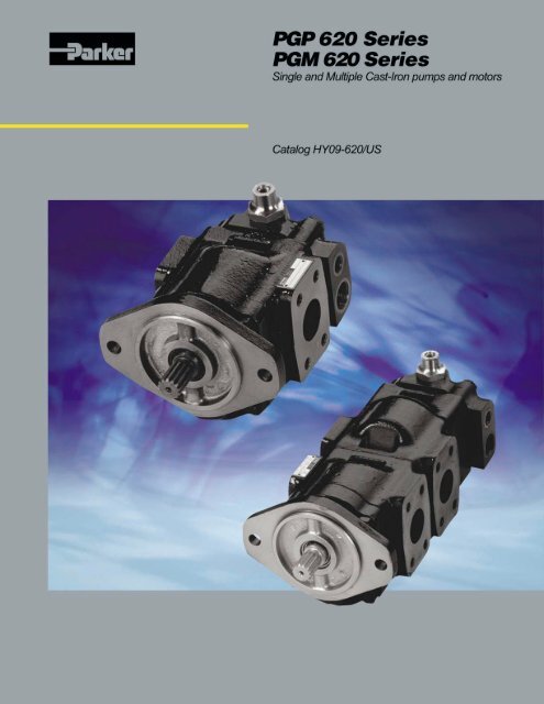
<strong>PGP</strong>/<strong>PGM</strong><strong>620</strong> Series<br />
Heavy-Duty Cast Iron Pumps and Motors<br />
The Gear Pump Division’s ability to engineer<br />
specialty products for unique applications has<br />
kept us at the forefront of technology, and<br />
ensured our position as the industry leader.<br />
Our success has come from providing a<br />
quality product with excellent sales and<br />
service support.<br />
We manufacture<br />
hydraulic components<br />
for a wide range of<br />
industries including:<br />
• Construction<br />
• Refuse/dump truck<br />
• Material handling<br />
• Forestry<br />
• Agriculture<br />
• Industrial<br />
• Turf care<br />
WARNING<br />
FAILURE OR IMPROPER SELECTION OR IMPROPER USE OF THE PRODUCTS AND/OR SYSTEMS DESCRIBED HEREIN OR RELATED ITEMS CAN CAUSE DEATH, PERSONAL<br />
INJURY AND PROPERTY DAMAGE.<br />
This document and other information from Parker Hannifin Corporation, its subsidiaries and authorized distributors provide product and/or system options for further investigation by users<br />
having technical expertise. It is important that you analyze all aspects of your application and review the information concerning the product or system in the current product catalog. Due<br />
to the variety of operating conditions and applications for these products or systems, the user, through its own analysis and testing, is solely responsible for making the final selection of<br />
the products and systems and assuring that all performance, safety and warning requirements of the application are met.<br />
The products described herein, including without limitation, product features, specifications, designs, availability and pricing, are subject to change by Parker Hannifin Corporation and its<br />
subsidiaries at any time without notice.<br />
Offer of Sale<br />
The items described in this document are hereby offered for sale by Parker Hannifin Corporation, its subsidiaries or its authorized distributors. This offer and its acceptance are governed<br />
by the provisions stated in the “Offer of Sale”.<br />
© Copyright 2003, Parker Hannifin Corporation, All Rights Reserved.<br />
2<br />
Parker Hannifin Corporation<br />
Gear Pump Division<br />
Youngstown, Ohio USA
Catalog HY09-<strong>620</strong>/US<br />
Table of Contents<br />
<strong>PGP</strong>/<strong>PGM</strong><strong>620</strong> Series<br />
Heavy-Duty Cast Iron Pumps and Motors<br />
Table of Contents<br />
SERIES <strong>620</strong> CAST IRON:<br />
Description and Characteristics ...................................................... 3<br />
<strong>PGP</strong>/<strong>PGM</strong> <strong>620</strong><br />
Features of <strong>PGP</strong><strong>620</strong>/<strong>PGM</strong><strong>620</strong> ........................................................ 4<br />
Ordering Code .................................................................................. 5<br />
Specifications .................................................................................. 6<br />
Dimensions ....................................................................................... 7<br />
Mounting Flange Options ............................................................... 8<br />
Port Options ...................................................................................... 9<br />
Drive Shaft Options ....................................................................... 11<br />
Performance Data ......................................................................... 13<br />
Valve Options For Motors ........................................................... 20<br />
Single Pressure Relief Valve with Anti-Cavitaion ................... 20<br />
Cross Port Pressure Relief Valve with Anti-Cavitation .......... 20<br />
Solenoid Unloading Pressure Relief Valve for Motors ........... 21<br />
Check Valve and Restrictor ......................................................... 21<br />
Offer of Sale ..................................................................................... 22<br />
Valve Options For Pumps ............................................................. 14<br />
Pressure Relief Valve ................................................................... 14<br />
Solenoid Unloading Pressure Relief Valve ............................... 15<br />
Unloading Relief Valve, Pressure Operated ............................. 15<br />
Unloading Relief Valve, Solenoid Operated ............................. 16<br />
Priority Flow Divider .................................................................... 16<br />
Load Sense Priority Valve ............................................................ 17<br />
Two–Stage Pump ........................................................................... 17<br />
Single Accumulator Charge Valve .............................................. 18<br />
Dual Accumulator Charge Valve ................................................ 18<br />
Steering and Accumulator Charge (STAC) Valve .................... 19<br />
Composite Priority and Accumulator Charge Valve ............... 19<br />
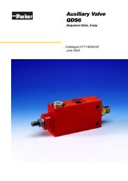
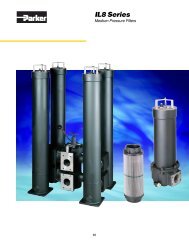
Pump/Motor Products<br />
<strong>PGP</strong>/<strong>PGM</strong> <strong>620</strong><br />
• 41 gpm @ 3,000 rpm<br />
• Pressures to 275 bar<br />
• Speeds to 3500 RPM<br />
3<br />
Parker Hannifin Corporation<br />
Gear Pump Division<br />
Youngstown, Ohio USA
Catalog HY09-<strong>620</strong>/US<br />
Features of <strong>PGP</strong>/<strong>PGM</strong><strong>620</strong><br />
<strong>PGP</strong>/<strong>PGM</strong> <strong>620</strong><br />
Parker Hydraulics has supplied gear pumps and motors<br />
to worldwide mobile and industrial markets for many<br />
years, especially material handling, turf care, and<br />
construction equipment applications. Many Parker<br />
pumps and motors have been developed and tested for<br />
the specific needs of these industries.<br />
Parker’s defined strategy to provide engineered<br />
solutions, coupled with an award-winning flexible<br />
manufacturing system has resulted in a wide range<br />
of SAE/DIN/European and other special options<br />
being available as standard.<br />
Features of <strong>PGP</strong>/<strong>PGM</strong> <strong>620</strong><br />
■ Patented, interlocking body design<br />
■ 12 tooth gears, bronze thrust plates<br />
■ Tandem, triple and cross-frame pumps available<br />
■ Common inlets available for tandem<br />
and triple pumps<br />
■ Continuous operating pressures up to 275 bar<br />
■ Production run-in available to suit OEM<br />
application conditions and to provide<br />
optimized volumetric efficiencies<br />
<strong>PGP</strong>/<strong>PGM</strong><strong>620</strong> Series<br />
Heavy-Duty Cast Iron Pumps and Motors<br />
<strong>PGP</strong> <strong>620</strong><br />
■ Pressure balanced design for high efficiency<br />
■ Reduced system noise levels compared to earlier<br />
models and competitors' pumps<br />
■ High power through-drive capability<br />
■ Wide range of integral valves for power steering,<br />
power brakes, fan drives and implement hydraulics<br />
■ Load sense and solenoid-operated<br />
unloading valves<br />
Characteristics<br />
Product Features<br />
Pump type<br />
Mounting<br />
Ports<br />
Shaft style<br />
Speed<br />
Theor. displacem.<br />
Drive<br />
Inlet pressure<br />
Outlet pressure<br />
Axial / Radial load<br />
Hydraulic fluids<br />
Fluid temperature<br />
Description<br />
Heavy-duty, cast iron, external gear.<br />
SAE, Rectangular. Specials on request.<br />
SAE and metric split flanges and others.<br />
SAE splined, keyed, tapered, cylindrical.<br />
Specials on request.<br />
500 - 3500 rpm, see tables.<br />
See tables<br />
Drive direct with flexible coupling<br />
is recommended.<br />
Operating range absolute pressure<br />
0.8 to 2 bar. Absolute minimum inlet<br />
pressure 0.5 bar, short time without load.<br />
Consultation is recommended.<br />
See tables<br />
Axial or Radial loading is not allowed.<br />
Mineral oil<br />
Fire resistant fluids:<br />
- water-oil emulsions 60/40, HFB<br />
- water-glycol, HFC<br />
- phosphate-esters, HFD<br />
Engineering approval is recommended.<br />
Range of operating temperature<br />
-15 to +80°C. Max. permissible<br />
operating pressure dependent on fluid<br />
temperature. Temperature for cold start<br />
-20 to -15°C at speed ≤ 1500 rpm.<br />
Max. permissible operating pressure<br />
dependent on fluid temperature.<br />
Product Features<br />
Fluid viscosity<br />
Description<br />
Range of operating viscosity<br />
20 to 100 mm²/s.<br />
Max. operating viscosity should<br />
not exceed 1000 mm²/s.<br />
Recommended min. viscosity 8 mm²/s.<br />
Range of ambient<br />
temperature<br />
-40°C - +70°C<br />
Filtration According to ISO 4406 Cl. 16/13<br />
Flow velocity<br />
See tables.<br />
Direction of rotation Clockwise, counter-clockwise or double.<br />
Multiple pump<br />
assemblies<br />
Separate or common<br />
inlet capability<br />
- Available in two or three section<br />
configurations.<br />
- Max. shaft loading must conform to<br />
the limitations shown in the Shaft Load<br />
Rating table in this catalog.<br />
- The max. load is determined by adding<br />
the torque values for each pumping<br />
section that will be simultaneously<br />
loaded.<br />
Separate Inlet configuration:<br />
- Each gear housing has individual inlet<br />
and outlet ports.<br />
Common Inlet configuration:<br />
- Two or more gear sets share<br />
a common inlet.<br />
4<br />
Parker Hannifin Corporation<br />
Gear Pump Division<br />
Youngstown, Ohio USA
Catalog HY09-<strong>620</strong>/US<br />
Ordering Code<br />
<strong>PGP</strong>/<strong>PGM</strong> <strong>620</strong> How to Specify<br />
<strong>PGP</strong>/<strong>PGM</strong><strong>620</strong> Series<br />
Heavy-Duty Cast Iron Pumps and Motors<br />
Omit for Tandem<br />
Omit for Triples Omit for Pumps<br />
Gear<br />
Design<br />
Side<br />
Suction<br />
Port<br />
Side<br />
Pressure<br />
Port<br />
Rear<br />
Suction<br />
Port 1<br />
Rear<br />
Pressure<br />
Port 1<br />
PG <strong>620</strong> <strong>620</strong><br />
Multi<br />
Sect.<br />
Only<br />
Side<br />
Suction<br />
Port<br />
Side<br />
Pressure<br />
Port<br />
Rear<br />
Suction<br />
Port 1<br />
Rear<br />
Pressure<br />
Port 1<br />
Pump/Motor<br />
P<br />
M<br />
Unit<br />
Pump<br />
Motor<br />
Pump Motor<br />
A Single unit Standard Motor<br />
w/o checks<br />
B Multiple unit Standard Motor<br />
w/ two checks<br />
C — Standard Motor<br />
w/one anti<br />
cavitation<br />
check (ACC)<br />
S* Single split —<br />
gear unit<br />
T* Multi. split —<br />
gear unit<br />
*Note: Only for displacement<br />
codes 0190 to 0460<br />
Displacement<br />
0160 16 ccm (0.98 cir)<br />
0190 19 ccm (1.16 cir)<br />
0210 21 ccm (1.28 cir)<br />
0230 23 ccm (1.40 cir)<br />
0260 26 ccm (1.59 cir)<br />
0290 29 ccm (1.77 cir)<br />
0330 33 ccm (2.01 cir)<br />
0360 36 ccm (2.20 cir)<br />
0370 37 ccm (2.26 cir)<br />
0410 41 ccm (2.50 cir)<br />
0440 44 ccm (2.68 cir)<br />
0460 46 ccm (2.81 cir)<br />
0500 50 ccm (3.05 cir)<br />
0520 52 ccm (3.17 cir)<br />
Rotation<br />
C Clockwise<br />
A Counter<br />
clockwise<br />
B Bi-directnl.<br />
1 Only coded for the last section.<br />
2 Only for motors<br />
Shaft<br />
B1<br />
C1<br />
10T, 16/32DP,<br />
32L spline<br />
11T, 16/32DP, 38.2L,<br />
SAE 19-4 spline<br />
D1 13T, 16/32DP, 41.2L,<br />
SAE "B" spline<br />
E1 15T, 16/32DP, 46L,<br />
SAE "B-B" spline<br />
M3 Ø25.4, 6.3Key, M8,<br />
46L, SAE "B-B",<br />
parallel<br />
M4 Ø25.0, 8.0Key,<br />
M8, 72L, parallel<br />
M6 Ø22.2, 4.8Key,<br />
no thread, 53.8L,<br />
parallel<br />
T1<br />
T2<br />
Ø21.59, 11.2L,<br />
4.0Key, M14x1.5,<br />
taper 1:8<br />
Ø25, 12L, 5.0Key,<br />
M16x1.5, taper 1:5<br />
Flange<br />
A3 89.8x89.8 - Ø101.6,<br />
SAE "B" 4bolt square<br />
A4 114.5x114.5 - Ø127,<br />
SAE "C" 4bolt square<br />
D7 98.4x128.2 - Ø50.77<br />
rectangular<br />
H2 106.4 - Ø82.55<br />
SAE "A" 2bolt flange<br />
H3 146.1 - Ø101.6<br />
SAE "B" 2bolt flange<br />
Shaft Seal<br />
X<br />
N<br />
V<br />
M<br />
W<br />
H<br />
No seal<br />
NBR (Buna-N)<br />
FPM, FKM<br />
(Fluorocarbon)<br />
Double NBR<br />
(Buna-N)<br />
Double FPM<br />
(Fluorocarbon)<br />
High Pres.(5bar)<br />
Port Options<br />
B1 No ports<br />
D3 ¾ - 16 UNF thread<br />
D4<br />
7 /8 - 14 UNF thread<br />
D5 1 1 /16 - 12UN<br />
D6* 1 5 /16 - 12 UN thread<br />
D7* 1 5 /8 - 12 UN thread<br />
D8* 1 7 /8 - 12 UN thread<br />
E2<br />
3 /8 - 19BSP thread<br />
E3 ½ - 14 BSP thread<br />
E4* 5 /8 - 14 BSP thread<br />
E5* ¾ - 16BSP thread<br />
E6* 1 - 11 BSP thread<br />
E7* 1¼ - 11 BSP thread<br />
E8* 1½ - 11 BSP thread<br />
J5* 15mm - Ø35mm - M6 sq Flange<br />
J9* 26mm - Ø55mm - M8 sq<br />
L1* 13mm-Ø30mm-M6 diamond<br />
L2* 19mm-Ø40mm-M8 diamond<br />
L3* 27mm-Ø51mm-M10 diamond<br />
N1* ½"- 5 /16-18UNC SAE Split Flange<br />
N2* ¾"- 3 /8-16UNC SAE Split Flange<br />
N3* 1"- 3 /8-16UNC SAE Split Flange<br />
N4* 1¼"- 7 /16-14UNC SAE Split Flange<br />
N5* 1½"-½ -13UNC SAE Split Flange<br />
N6* 2"½-13UNC SAE Split Flange<br />
P1* 12.7mm-M8 Metric Split Flange<br />
P2* 19.0mm-M10 Metric Split Flange<br />
P3* 25.4mm-M10 Metric Split Flange<br />
P4* 31.8mm-M10 Metric Split Flange<br />
P5* 38.1mm-M12 Metric Split Flange<br />
P6* 50.8mm-M12 Metric Split Flange<br />
*Note: Not usable for rear ports.<br />
Motor Drain Option 2<br />
B1<br />
C<br />
G<br />
Drain Position 2<br />
2 Drain on bottom<br />
3 Drain on top<br />
4 Rear drain<br />
Section Connection<br />
S<br />
C<br />
No drain<br />
9/16-18 UNF thread<br />
1/4 BSP thread<br />
Seperate inlets<br />
(no common passage)<br />
Common inlet (passage)<br />
Note<br />
Further "B" triple<br />
unit repeat<br />
displacement,<br />
shaft seal between<br />
sections, side<br />
suction port, side<br />
pressure port, rear<br />
suction port, rear<br />
pressure port.<br />
Note<br />
See Port Options<br />
Note<br />
See Shaft Seal<br />
Options.<br />
Note<br />
See Displacement<br />
Options<br />
Note<br />
See Rotation and<br />
Shaft Options; use<br />
only for Unit A or B<br />
configurations<br />
only.<br />
5<br />
Parker Hannifin Corporation<br />
Gear Pump Division<br />
Youngstown, Ohio USA
Catalog HY09-<strong>620</strong>/US<br />
Specifications<br />
<strong>PGP</strong>/<strong>PGM</strong><strong>620</strong> Series<br />
Heavy-Duty Cast Iron Pumps and Motors<br />
<strong>PGP</strong>/<strong>PGM</strong> <strong>620</strong> Dimensions<br />
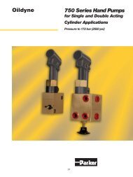
<strong>PGP</strong>/<strong>PGM</strong> <strong>620</strong> Specification - Standard Displacements - Single Unit<br />
Pump Displacement Code 0160 0190 0210 0230 0260 0290 0330 0360 0370 0410 0440 0460 0500 0520<br />
cm³/rev 16.0 19.0 21.0 23.0 26.0 29.0 33.0 36.0 37.0 41.0 44.0 46.0 50.0 52.0<br />
in ³/rev .98 1.16 1.28 1.4 1.6 1.8 2.01 2.2 2.3 2.5 2.7 2.8 3.1 3.2<br />
Continuous Press. bar 275 275 275 275 275 275 275 250 250 220 210 210 210 210<br />
psi<br />
Intermittent Press. bar 300 300 300 300 300 300 300 275 275 245 230 220 210 210<br />
psi<br />
Minimum Speed rpm 500 500 500 500 500 500 500 500 500 500 500 500 500 500<br />
@ Max. outlet press.<br />
Maximum Speed rpm 3500 3500 3500 3500 3500 3500 3500 3500 3500 3500 3500 3500 3000 3000<br />
@ 0 Inlet & Max. outlet press.<br />
Dimension "X" mm 79.2 82.5 84.7 86.9 90.2 93.5 97.9 101.2 102.3 106.7 110.0 112.2 116.6 118.8<br />
in 3.1 3.2 3.3 3.4 3.6 3.7 3.9 4.0 4.0 4.2 4.3 4.4 4.6 4.7<br />
Dimension "Y" mm 120.2 123.5 125.7 127.9 131.2 134.5 138.9 142.2 143.3 147.7 151.0 153.2 157.6 159.8<br />
in 4.7 4.9 4.9 5.0 5.2 5.3 5.5 5.6 5.6 5.8 5.9 6.0 6.2 6.3<br />
Approx. Weight kg 12.0 12.1 12.1 12.2 12.3 12.6 12.7 12.8 12.9 13.0 13.1 13.2 13.3 13.4<br />
lb 26.4 26.6 26.6 26.8 27.1 27.7 27.9 28.1 28.4 28.6 28.8 29.04 29.3 29.5<br />
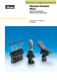
Single Unit <strong>PGP</strong>/<strong>PGM</strong> <strong>620</strong><br />
Inch equivalents for millimeter dimensions are shown in (**).<br />
20.32<br />
(0.8)<br />
134 across body<br />
(5.3)<br />
27<br />
(1.1)<br />
27<br />
(1.1)<br />
Dim ‘Y’ ±0.5<br />
Dim ‘X’ ±0.5<br />
50.8 max.<br />
(2.0)<br />
20.32<br />
(0.8)<br />
142.2 max.<br />
(5.6)<br />
6<br />
Parker Hannifin Corporation<br />
Gear Pump Division<br />
Youngstown, Ohio USA
Catalog HY09-<strong>620</strong>/US<br />
Dimensions<br />
<strong>PGP</strong>/<strong>PGM</strong><strong>620</strong> Series<br />
Heavy-Duty Cast Iron Pumps and Motors<br />
<strong>PGP</strong>/<strong>PGM</strong> <strong>620</strong> Dimensions<br />
<strong>PGP</strong>/<strong>PGM</strong> <strong>620</strong> Specification - Standard Displacements - Tandem Unit<br />
Pump Displacement Code 0160 0190 0210 0230 0260 0290 0330 0360 0370 0410 0440 0460 0500 0520<br />
cm³/rev 16.0 19.0 21.0 23.0 26.0 29.0 33.0 36.0 37.0 41.0 44.0 46.0 50.0 52.0<br />
in³/rev<br />
Dimension "X" mm 79.2 82.5 84.7 86.9 90.2 93.5 97.9 101.2 102.3 106.7 110.0 112.2 116.6 118.8<br />
in 3.1 3.2 3.3 3.4 3.5 3.7 3.9 4.0 4.0 4.2 4.3 4.4 4.6 4.7<br />
Dimension "Y1 " mm 120.2 123.5 125.7 127.9 131.2 134.5 138.9 142.2 143.3 147.7 151.0 153.2 157.6 159.8<br />
in 4.7 4.9 4.9 5.0 5.2 5.3 5.5 5.6 5.6 5.8 5.9 6.0 6.2 6.3<br />
Dimension "Y2" max. mm 115.2 118.5 120.7 122.9 126.2 129.5 133.9 137.2 138.3 142.7 146.0 148.2 152.6 154.8<br />
in 4.5 4.7 4.8 4.8 5.0 5.1 5.3 5.4 5.4 5.6 5.7 5.8 6.0 6.1<br />
Approximate Weight kg 12.0 12.1 12.1 12.2 12.3 12.6 12.7 12.8 12.9 13.0 13.1 13.2 13.3 13.4<br />
(front section) lb 26.4 26.62 26.62 26.84 27.06 27.72 27.94 28.16 28.38 28.6 28.82 29.04 29.26 29.48<br />
Approximate Weight kg 10.4 10.5 10.5 10.6 10.7 11.0 11.1 11.2 11.3 11.4 11.5 11.6 11.7 11.8<br />
(rear section) lb 22.88 23.10 23.10 23.32 23.54 24.2 24.42 24.64 24.86 25.08 25.3 25.52 25.74 25.96<br />
Tandem Unit <strong>PGP</strong>/<strong>PGM</strong> <strong>620</strong><br />
Inch equivalents for millimeter dimensions are shown in (**).<br />
20.32<br />
(0.8)<br />
134 across body<br />
(5.28)<br />
Dim ‘Y1’<br />
Dim ‘Y2’ max.<br />
Dim ‘X’ ±0.5 41 ±1<br />
(1.6)<br />
50.8 max.<br />
(2.0)<br />
20.32<br />
(0.8)<br />
142.2 max.<br />
(5.6)<br />
7<br />
Parker Hannifin Corporation<br />
Gear Pump Division<br />
Youngstown, Ohio USA
Catalog HY09-<strong>620</strong>/US<br />
Mounting Flange Options<br />
<strong>PGP</strong>/<strong>PGM</strong> <strong>620</strong> Mounting Flange<br />
<strong>PGP</strong>/<strong>PGM</strong><strong>620</strong> Series<br />
Heavy-Duty Cast Iron Pumps and Motors<br />
Inch equivalents for millimeter dimensions are shown in (**).<br />
Code A3<br />
Code A4<br />
9.4<br />
(0.37)<br />
14<br />
(0.55)<br />
118<br />
(4.65)<br />
44.9 44.9<br />
(1.77) (1.77)<br />
9.7<br />
(0.38)<br />
14<br />
(0.55)<br />
147<br />
(5.79)<br />
57.25 57.25<br />
(2.25) (2.25)<br />
Ø 101.6<br />
(4.0)<br />
-0.05<br />
20.3<br />
(0.8)<br />
121<br />
Ø 14.3 (4.76)<br />
(0.56)<br />
44.9<br />
(1.77)<br />
151.1<br />
(4.61)<br />
44.9<br />
(1.77)<br />
Ø 127<br />
(5.0)<br />
-0.05<br />
20.3<br />
(0.80)<br />
151<br />
(5.9)<br />
Ø 14.3<br />
(0.56)<br />
57.25<br />
(2.25)<br />
166.1<br />
(6.54)<br />
57.25<br />
(2.25)<br />
55.5<br />
(2.19)<br />
108<br />
(4.25)<br />
55.5<br />
(2.2)<br />
Code D7<br />
Code H2<br />
5.1 21.5<br />
(0.03) (0.85)<br />
122<br />
(4.8)<br />
98.4<br />
(3.87)<br />
6.4<br />
(0.25)<br />
12<br />
(0.47)<br />
132 max.<br />
(5.2)<br />
106.4<br />
(4.2)<br />
152<br />
(5.98)<br />
54.9<br />
(2.16)<br />
128<br />
(5.03)<br />
42.65<br />
(1.68)<br />
Ø 82.55<br />
(3.25)<br />
-0.05<br />
20.3<br />
(0.8)<br />
Ø 11<br />
(0.43)<br />
140.6<br />
(5.54)<br />
47.5<br />
(1.87)<br />
-0.05<br />
20.3<br />
(0.8)<br />
Ø 50.77<br />
(2.0)<br />
55.5 108<br />
(2.12)<br />
(4.25)<br />
55.5<br />
(2.19)<br />
Ø 12.5<br />
(0.49)<br />
Code H3<br />
5.1<br />
(0.2)<br />
14<br />
(0.55)<br />
176.2 max.<br />
(6.94)<br />
146<br />
(5.75)<br />
-0.05<br />
60.5<br />
(2.38)<br />
Ø 101.6<br />
(4.0)<br />
20.3<br />
(0.80)<br />
Ø 14.3<br />
(0.56)<br />
151.1<br />
(5.95)<br />
55.5<br />
(2.19)<br />
108<br />
(4.25)<br />
8<br />
Parker Hannifin Corporation<br />
Gear Pump Division<br />
Youngstown, Ohio USA
Catalog HY09-<strong>620</strong>/US<br />
Port Options<br />
<strong>PGP</strong>/<strong>PGM</strong> <strong>620</strong> Porting<br />
<strong>PGP</strong>/<strong>PGM</strong><strong>620</strong> Series<br />
Heavy-Duty Cast Iron Pumps and Motors<br />
Inch equivalents for millimeter dimensions are shown in (**).<br />
Code L<br />
4-Bolt flange<br />
Code J<br />
European flange<br />
Code N<br />
SAE split flange<br />
G2<br />
Code P<br />
SAE split flange metric<br />
thread<br />
G2<br />
T2<br />
T2<br />
W<br />
W<br />
Ø B<br />
C<br />
Ø B<br />
C<br />
Code D<br />
SAE straight thread<br />
G1<br />
Code E<br />
BSP - thread<br />
G1<br />
T1<br />
T1<br />
9<br />
Parker Hannifin Corporation<br />
Gear Pump Division<br />
Youngstown, Ohio USA
Catalog HY09-<strong>620</strong>/US<br />
Port Options<br />
<strong>PGP</strong>/<strong>PGM</strong> <strong>620</strong><br />
G2 ∅ B ∅ D C W T2<br />
Code Thread Dimensions<br />
J5 M6 15.0 35.0 12.5<br />
(0.59) (1.38) (0.49)<br />
J9 M8 26.0 55.0 15.0<br />
(1.02) (2.17) (0.59)<br />
L1 M6 13.0 30.0 13.0<br />
(0.5) (1.18) (0.5)<br />
L2 M8 19.0 40.0 15.0<br />
(0.75) (1.57) (0.59)<br />
L3 M10 27.0 51.0 18.0<br />
(1.06) (2.01) (0.71)<br />
N1 5/16-18 UNC 12.7 38.10 17.48 15.0<br />
(0.5) (1.5) (0.69) (0.59)<br />
N2 3/8-16 UNC 19.0 47.63 22.23 14.0<br />
(0.75) (1.88) (0.88) (0.55)<br />
N3 3/8-16 UNC 25.4 52.37 26.19 20.6<br />
(1.0) (2.06) (1.03) (0.81)<br />
N4 7/16-14 UNC 31.8 58.72 30.17 20.6<br />
(1.25) (2.31) (1.19) (0.81)<br />
N5 1/2-13 UNC 38.1 69.82 35.71 20.6<br />
(1.5) (2.75) (1.4) (0.81)<br />
N6 1/2-13 UNC 50.8 77.77 42.88 20.6<br />
(2.0) (3.06) (1.69) (0.81)<br />
P1 M8 12.7 38.10 17.48 15.0<br />
(0.5) (1.5) (0.69) (0.59)<br />
<strong>PGP</strong>/<strong>PGM</strong><strong>620</strong> Series<br />
Heavy-Duty Cast Iron Pumps and Motors<br />
<strong>PGP</strong>/<strong>PGM</strong> <strong>620</strong><br />
G1<br />
T1<br />
Code Thread Dimensions<br />
D3 3/4-16 UNF 14.3 (0.56)<br />
D4 7/8-14 UNF 16.7 (0.68)<br />
D5 1 1/16-12 UN 19.0 (0.75)<br />
D6 1 5/16-12 UN 19.0 (0.75)<br />
D7 1 5/8-12 UN 19.0 (0.75)<br />
D8 1 7/8-12 UN 19.0 (0.75)<br />
E2 3/8-19 BSP 12.0 (0.47)<br />
E3 1/2-14 BSP 14.0 (0.55)<br />
E4 5/8-14 BSP 16.3 (0.64)<br />
E5 3/4-16 BSP 16.0 (0.63)<br />
E6 1-11 BSP 18.0 (0.71)<br />
E7 1 1/4-11 BSP 20.0 (0.79)<br />
E8 1 1/2-11 BSP 22.0 (0.87)<br />
Inch equivalents for millimeter dimensions are shown in (**).<br />
P2 M10 19.0 47.63 22.23 20.6<br />
(0.75) (1.88) (0.88) (0.81)<br />
P3 M10 25.4 52.37 26.19 21.4<br />
(1.0) (2.06) (1.03) (0.84)<br />
P4 M10 31.8 58.72 30.17 20.6<br />
(1.25) (2.31) (1.19) (0.81)<br />
P5 M12 38.1 69.82 35.71 20.6<br />
(1.5) (2.75) (1.41) (0.81)<br />
P6 M12 50.8 77.77 42.88 20.6<br />
(2) (3.06) (1.69) (0.81)<br />
10<br />
Parker Hannifin Corporation<br />
Gear Pump Division<br />
Youngstown, Ohio USA
Catalog HY09-<strong>620</strong>/US<br />
Drive Shaft Options<br />
<strong>PGP</strong>/<strong>PGM</strong> <strong>620</strong> Drive Shaft<br />
Code B1<br />
<strong>PGP</strong>/<strong>PGM</strong><strong>620</strong> Series<br />
Heavy-Duty Cast Iron Pumps and Motors<br />
Code C1<br />
Inch equivalents for millimeter dimensions are shown in (**).<br />
Spline<br />
10T - 16/32 DP<br />
Flat root side fit<br />
24.1<br />
(0.95)<br />
Spline SAE 19-4<br />
11T - 16/32 DP<br />
Flat root side fit<br />
30.3<br />
(1.19)<br />
16.5<br />
(0.65)<br />
22.7<br />
(0.9)<br />
Ø 25.4<br />
Ø 13.5<br />
(0.5)<br />
Ø 25.4<br />
(1.0)<br />
Ø 15.0<br />
(0.6)<br />
32<br />
(1.26)<br />
38.2<br />
(1.5)<br />
Code D1<br />
Code E1<br />
Spline SAE “B”<br />
13T - 16/32 DP<br />
Flat root side fit<br />
33.3<br />
(1.31)<br />
25.7<br />
(1.01)<br />
Spline SAE “B”-”B”<br />
15T - 16/32 DP<br />
Flat root side fit 38.1<br />
(1.5)<br />
30.5<br />
(1.2)<br />
Ø 25.4<br />
(1.0)<br />
Ø 18.3<br />
(0.72)<br />
Ø 25.4<br />
(1.0)<br />
Ø 21.5<br />
(0.85)<br />
46<br />
(1.8)<br />
41.2<br />
(1.62)<br />
Code M3<br />
Code M4<br />
Square key<br />
6.3x6.3x31.7 31.7<br />
(1.25)<br />
3<br />
(0.12)<br />
Rect. Key<br />
8x7x55<br />
55<br />
(2.17)<br />
3<br />
(0.12)<br />
6.3<br />
(0.25)<br />
Ø 27<br />
(1.06)<br />
Ø 25.4<br />
(1.0)<br />
19<br />
(0.75)<br />
38.6<br />
(1.5)<br />
M8x1.25<br />
(0.05)<br />
-0.05<br />
-0.2<br />
Ø 25.4<br />
(1.0)<br />
28.2<br />
(1.11)<br />
8<br />
(0.31)<br />
Ø 27<br />
(1.06)<br />
Ø 25.4<br />
(1.0)<br />
19<br />
(0.75)<br />
64.0<br />
(2.5)<br />
M8x1.25<br />
-0.05<br />
Ø 25<br />
(0.98)<br />
-0.2<br />
Ø 28.2<br />
(1.11)<br />
46<br />
(1.8)<br />
Circlip of 1.6<br />
(0.06)<br />
72<br />
(2.8)<br />
Circlip of 1.6<br />
11<br />
Parker Hannifin Corporation<br />
Gear Pump Division<br />
Youngstown, Ohio USA
Catalog HY09-<strong>620</strong>/US<br />
Drive Shaft Options<br />
<strong>PGP</strong>/<strong>PGM</strong> <strong>620</strong> Drive Shaft<br />
Code M6<br />
<strong>PGP</strong>/<strong>PGM</strong><strong>620</strong> Series<br />
Heavy-Duty Cast Iron Pumps and Motors<br />
Code T1<br />
Inch equivalents for millimeter dimensions are shown in (**).<br />
Square key<br />
4.8x4.8x38.1<br />
38.1<br />
(1.5)<br />
3<br />
(0.12)<br />
Woodruff key<br />
4x7.5 DIN 6888<br />
1.5<br />
(0.06)<br />
20.3<br />
(0.8)<br />
15<br />
(0.6)<br />
Spring washer<br />
Nut<br />
M14x1.5<br />
Ø 25.4<br />
(1.0)<br />
45.6<br />
(1.8)<br />
-0.025<br />
Ø 22.23<br />
-0.2<br />
24.5<br />
(0.96)<br />
11.2<br />
(0.44)<br />
Taper 1:8<br />
Ø 25.4<br />
(1.0)<br />
Ø 21.59<br />
(0.85)<br />
M14x1.5<br />
47<br />
(1.85)<br />
53.8<br />
(2.12)<br />
Code T2<br />
Woodruff key<br />
5x7.5 DIN 6888<br />
25.0<br />
(.98)<br />
15<br />
(0.6)<br />
Spring washer<br />
Nut<br />
DIN 934 M16x1.5<br />
2.4<br />
(0.09)<br />
11<br />
(0.4)<br />
Taper 1:5<br />
Ø 27<br />
(1.06)<br />
Ø 25<br />
(0.98)<br />
M16x1.5<br />
51<br />
(2.0)<br />
<strong>PGP</strong>/<strong>PGM</strong> <strong>620</strong>- Shaft Load Capacity<br />
Code Description Torque Rating<br />
[Nm]<br />
B1 10T,16/32 DP, 32L spline 124<br />
C1 11T,16/32 DP, 38.2L, SAE 19-4 spline 144<br />
D1 13T,16/32 DP, 41.2L, SAE “B“ spline 272<br />
E1 15T,16/32 DP, 46L, SAE “B-B“ spline 460<br />
M3 Ø25.4,6.3 KEY, M8, 46L, SAE “B-B“ keyed 325<br />
M4 Ø25.0,8.0 KEY, M8, 72L keyed 325<br />
M6 Ø22.2,4.8 KEY, no thread, 53.8L keyed 218<br />
T1 Ø21.59,11.2L, 4.0 KEY, M14x1.5 taper 1:8 218<br />
T2 Ø25.0,12.0L, 5.0 KEY, M16x1.5 taper 1:5 301<br />
Torque [Nm] = Displacement [cm3 /rev] x Pressure [bar]<br />
57.2<br />
12<br />
Parker Hannifin Corporation<br />
Gear Pump Division<br />
Youngstown, Ohio USA
Catalog HY09-<strong>620</strong>/US<br />
Performance Data<br />
<strong>PGP</strong>/<strong>PGM</strong><strong>620</strong> Series<br />
Heavy-Duty Cast Iron Pumps and Motors<br />
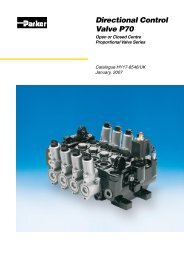
<strong>PGP</strong> <strong>620</strong> - 16.0 CC<br />
<strong>PGP</strong> <strong>620</strong> - 26.0 CC<br />
Fluid Temperature = 45± 2°C<br />
Viscosity = 36mm 2 /s<br />
Inlet Pressure<br />
= 0.9 + 0.1 bar absolute<br />
<strong>PGP</strong> <strong>620</strong> - 41.0 CC<br />
<strong>PGP</strong> <strong>620</strong> - 52.0 CC<br />
13<br />
Parker Hannifin Corporation<br />
Gear Pump Division<br />
Youngstown, Ohio USA
Catalog HY09-<strong>620</strong>/US<br />
Pump/Valve Options<br />
<strong>PGP</strong>/<strong>PGM</strong><strong>620</strong> Series<br />
Heavy-Duty Cast Iron Pumps and Motors<br />
Valve Options<br />
VALVE TYPE<br />
Pressure Relief Valve<br />
Load Sensing Pressure Relief Valve<br />
Solenoid Unloading Pressure Relief Valve<br />
Pressure Unloading Relief Valve (Port Mounted)<br />
Solenoid Unloading Relief Valve (Port Mounted)<br />
Priority Flow Divider<br />
Priority Flow Divider (Port Mounted)<br />
Load Sensing Priority Valve<br />
Load Sensing Priority Valve (Port Mounted)<br />
Two - Stage Pump<br />
Single Accumulator Charge Valve<br />
Dual Accumulator Charge Valve<br />
Steering and Accumulator Charge Valve (STAC)<br />
Composite Priority and Accumulator Charge Valve<br />
<strong>PGP</strong><br />
<strong>620</strong><br />
X<br />
X<br />
X<br />
X<br />
X<br />
X<br />
X<br />
X<br />
X<br />
X<br />
X<br />
X<br />
X<br />
X<br />
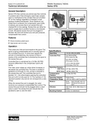
Pressure Relief Valve<br />
P1<br />
S<br />
non adjustable, internal vent<br />
adjustable, internal vent<br />
P1<br />
P1<br />
S T S<br />
T<br />
non adjustable, external tank port<br />
adjustable, external tank port<br />
Variations: For <strong>PGP</strong><strong>620</strong><br />
Non adjustable, internal vent<br />
Non adjustable, external tank port<br />
Adjustable, internal vent<br />
Adjustable, external tank port<br />
14<br />
Parker Hannifin Corporation<br />
Gear Pump Division<br />
Youngstown, Ohio USA
Catalog HY09-<strong>620</strong>/US<br />
Pump/Valve Options<br />
<strong>PGP</strong>/<strong>PGM</strong><strong>620</strong> Series<br />
Heavy-Duty Cast Iron Pumps and Motors<br />
Solenoid Unloading Pressure Relief Valve<br />
P1<br />
EF<br />
P1<br />
EF<br />
S<br />
Detailed Symbol: Normally closed (N/C)<br />
S<br />
Simplified Symbol<br />
Detailed Symbol<br />
Normally opened (N/O)<br />
Variations: For <strong>PGP</strong><strong>620</strong><br />
Specify voltage and whether N/O or N/C<br />
Press. Range: Stand-by pressure setting 5 bar<br />
Max. setting 250 bar<br />
Max. Flow: For <strong>PGP</strong><strong>620</strong> 100 l/min<br />
Comments:<br />
This valve utilizes the same casting, main spool, and pilot<br />
relief as the Load Sensing Pressure Relief Valve. A small<br />
solenoid operated cartridge valve vents the internal pilot flow<br />
to pump inlet to unload the main spool. The outlet port is in the<br />
pump body and the EF is connected to the reservoir via heat<br />
exchanger and/or return line filter.<br />
Unloading Relief Valve, Pressure Operated<br />
P1<br />
P2<br />
P1<br />
P2<br />
T<br />
S<br />
T<br />
S<br />
Detailed Symbol<br />
Simplified Symbol<br />
Variations: For <strong>PGP</strong> <strong>620</strong><br />
Port mounted, integral with pump<br />
Press. Range: Stand-by pressure setting 5 bar<br />
Max. setting 250 bar<br />
Min setting 55 bar<br />
Max. Flow:<br />
80 l/min<br />
Comments:<br />
This valve permits pressure unloading of the first section in a<br />
tandem. The valve may also be remote mounted for use with<br />
tandem or dual pumps. The flow from port P1 is typically<br />
combined with the flow from port P2. Often used on construction<br />
machinery, such as backhoe loaders, wheel loaders and<br />
cranes, to provide high flow (from both sections of the tandem)<br />
at low or medium pressures and high pressure with reduced<br />
flow (from the rear section only). This allows maximum productivity<br />
of the machine in accord with the power available to the<br />
pump.<br />
15<br />
Parker Hannifin Corporation<br />
Gear Pump Division<br />
Youngstown, Ohio USA
Catalog HY09-<strong>620</strong>/US<br />
Pump/Valve Options<br />
<strong>PGP</strong>/<strong>PGM</strong><strong>620</strong> Series<br />
Heavy-Duty Cast Iron Pumps and Motors<br />
Unloading Relief Valve, Solenoid Operated<br />
P1<br />
P2<br />
P1<br />
P2<br />
T<br />
S<br />
T<br />
Variations: For <strong>PGP</strong><strong>620</strong><br />
Port mounted, integral with pump<br />
Press. Range: Stand-by pressure setting 5 bar<br />
Max. setting 250 bar<br />
Min setting 55 bar<br />
Max. Flow:<br />
80 l/min<br />
S<br />
Detailed Symbol<br />
Simplified Symbol<br />
Comments:<br />
This valve permits pressure or solenoid unloading of the first<br />
section in a tandem. The valve may also be remote mounted for<br />
use with tandem or dual pumps. The flow from port P1 is typically<br />
combined with the flow from port P2. Often used on construction<br />
machinery, such as backhoe loaders, wheel loaders and cranes,<br />
to provide high flow (from both sections of the tandem) at low or<br />
medium pressures and high pressure with reduced flow (from the<br />
rear section only). This allows maximum productivity of the<br />
machine in accord with the power available to the pump.<br />
Priority Flow Divider<br />
P<br />
EF<br />
P<br />
EF<br />
Variations:<br />
<strong>PGP</strong> <strong>620</strong> + Valve<br />
With Pilot Priority Relief Valve<br />
Rear Mounted Versions:<br />
For <strong>PGP</strong><strong>620</strong><br />
Without priority relief; With full flow<br />
priority relief (not shown)<br />
With pilot priority relief valve<br />
Port Mounted Version:<br />
For <strong>PGP</strong> <strong>620</strong><br />
Without priority relief<br />
S<br />
S<br />
Without Priority Relief Valve<br />
Press. Range: Priority Port Min. setting 35 bar<br />
Priority Port Max. setting 210 bar<br />
Extended Flow Max. equal to max.<br />
rating of pump<br />
Max. Flow: Valve for Port Mounted Version<br />
Priority Flow Max.<br />
32 l/min<br />
Extended Flow Max.<br />
70 l/min<br />
Max. input flow<br />
70 l/min<br />
Valve for <strong>PGP</strong> <strong>620</strong> - Rear Mounted Version<br />
Priority Flow Max.<br />
45 l/min<br />
Extended Flow Max.<br />
100 l/min<br />
Max. input flow<br />
100 l/min<br />
Comments:<br />
The Priority Flow Divider provides a constant and specified flow for power steering or other<br />
priority functions. The balance of the flow produced by the pump is available from the EF port<br />
for additional functions such as open center directional control valves, fan drives, etc.<br />
16<br />
Parker Hannifin Corporation<br />
Gear Pump Division<br />
Youngstown, Ohio USA
Catalog HY09-<strong>620</strong>/US<br />
Pump/Valve Options<br />
<strong>PGP</strong>/<strong>PGM</strong><strong>620</strong> Series<br />
Heavy-Duty Cast Iron Pumps and Motors<br />
Load Sense Priority Valve<br />
LS P EF<br />
LS P EF<br />
With Priority Relief Valve and for Dynamic LS Signal<br />
S<br />
S<br />
Without Priority Relief Valve and for Dynamic LS Signal<br />
Variations:<br />
Rear Mounted Versions:<br />
For <strong>PGP</strong><strong>620</strong><br />
Without relief, static LS signal;<br />
With pilot relief, dynamic LS signal<br />
Without relief, dynamic LS signal;<br />
With pilot relief, dynamic LS signal<br />
Port Mounted Version:<br />
For <strong>PGP</strong><strong>620</strong><br />
Without relief, static LS signal;<br />
Without relief, dynamic LS signal<br />
Press. Range: Priority Port Min. setting 35 bar<br />
Priority Port Max. setting 210 ba<br />
Extended Flow Max. equal<br />
to max. rating of pump<br />
Max. Flow: Valve for Port Mounted Version<br />
Priority Flow Max. 32 l/min<br />
Extended Flow Max.<br />
70 l/min<br />
Max. input flow<br />
70 l/min<br />
Valve for <strong>PGP</strong><strong>620</strong><br />
Priority Flow Max. 45 l/min<br />
Extended Flow Max. 100 l/min<br />
Max. input flow 100 l/min<br />
Comments:<br />
The Load Sensing Priority Valve provides priority flow on demand, typically for LS power steering. The balance of the flow<br />
produced by the pump is available from the EF port for additional functions such as open center directional control valves, fan<br />
drives, etc. When the power steering is idle, full pump flow is available for these functions. The selection of pilot relief and static<br />
or dynamic signal is dependent on the characteristics of the selected steering unit.<br />
Two - Stage Pump<br />
P<br />
P<br />
S<br />
R<br />
S<br />
With External Tank Port (recommended)<br />
With Internal Vent to Pump Inlet<br />
Variations:<br />
For <strong>PGP</strong><strong>620</strong><br />
With internal vent to inlet<br />
With external tank port<br />
Note: Specifiy solenoid voltage<br />
Press. Range: To application requirements<br />
Rated Flow: A variety of solenoid valves are available.<br />
Selection of valve size and flow rate is in<br />
accordance with application requirements.<br />
Comments:<br />
The Parker Two-Stage or High-Low pump is a tandem with equal or dissimilar displacements and a two position / two way valve in the<br />
rear cover to allow unloading of the rear pump. This pump is applied when the prime mover (engine or electric motor) has limited power.<br />
When high pressure is required, the rear section is unloaded to the pump inlet or the tank. When high flow is required at low or medium<br />
pressure, the flow of both sections is combined at the outlet port P. In both cases, the displacements and pressures are selected to be<br />
within the power limits of the prime mover.<br />
Note: When the internal vent to the inlet is selected, caution is suggested to prevent operating in the unloading condition for extended<br />
periods. The heat generated in doing so may lower the fluid viscosity below minimums required for the pump possibly damaging the pump.<br />
17<br />
Parker Hannifin Corporation<br />
Gear Pump Division<br />
Youngstown, Ohio USA
Catalog HY09-<strong>620</strong>/US<br />
Pump/Valve Options<br />
<strong>PGP</strong>/<strong>PGM</strong><strong>620</strong> Series<br />
Heavy-Duty Cast Iron Pumps and Motors<br />
Single Accumulator Charge Valve<br />
A1<br />
G<br />
EF<br />
Variations: For <strong>PGP</strong><strong>620</strong><br />
Integral with pump<br />
100 l/min<br />
Press. Range: A1, G Ports Min. setting 35 bar<br />
A1, G Ports Max. setting 210 bar<br />
Extended Flow Max. equal to<br />
max. rating of pump<br />
Max. Flow: Valve for <strong>PGP</strong><strong>620</strong><br />
Charge Flow Max.<br />
45 l/min<br />
Extended Flow Max.<br />
100 l/min<br />
Max. Input Flow<br />
100 l/min<br />
S<br />
Comments:<br />
The Single Accumulator Charge Valve (SACV) provides priority flow to charge an accumulator for vehicle brakes or any<br />
application requiring stored hydraulic energy. The SACV has an integral differential pilot relief valve to provide a wide variety<br />
of cut-in/cut-out pressure ratios. Typical ratios are 80%, 70%, 60% and 50%. Custom ratios are available for OEM applications.<br />
A variety of port locations and sizes are available. The balance of the pump flow at the EF port is available for an open circuit<br />
directional control valve, fan drive or other ancillary functions.<br />
Dual Accumulator Charge Valve<br />
A1<br />
A2<br />
G<br />
EF<br />
Variations: For <strong>PGP</strong><strong>620</strong><br />
Integral with pump<br />
100 l/min<br />
Press. Range: A1, A2, G Ports Min. setting 35 bar<br />
A1, A2 G Ports Max. setting 210 bar<br />
Extended Flow Max. equal to<br />
max. rating of pump<br />
Max. Flow: Valve for <strong>PGP</strong><strong>620</strong><br />
Charge Flow Max.<br />
45 l/min<br />
Extended Flow Max.<br />
100 l/min<br />
Max. Input Flow<br />
100 l/min<br />
S<br />
Comments:<br />
The Dual Accumulator Charge Valve provides priority flow to charge two accumulators for dual circuit vehicle brakes or any<br />
application requiring stored hydraulic energy. The Dual Accumulator Charge Valve has an integral differential pilot relief valve<br />
to provide a wide variety of cut-in/cut-out pressure ratios. Typical ratios are 80%, 70%, 60% and 50%. Custom ratios are<br />
available for OEM applications. An inverse shuttle spool isolates the two circuits so that pressure and oil volume is maintained<br />
in one circuit should the other experience a break in the hydraulic line. A variety of port locations and sizes is available.<br />
18<br />
Parker Hannifin Corporation<br />
Gear Pump Division<br />
Youngstown, Ohio USA
Catalog HY09-<strong>620</strong>/US<br />
Pump/Valve Options<br />
<strong>PGP</strong>/<strong>PGM</strong><strong>620</strong> Series<br />
Heavy-Duty Cast Iron Pumps and Motors<br />
Steering & Accumulator Charge (STAC) Valve<br />
To Accumulator<br />
A1 A2<br />
G<br />
LS<br />
To Orbitrol<br />
Steering Unit<br />
P<br />
EF<br />
Variations: Integral with <strong>PGP</strong> <strong>620</strong> pump<br />
Single or dual accumulator charge circuit<br />
(Dual circuit schematic shown)<br />
Press. Range: A1, A2, Port Min. setting 35 bar<br />
A1, A2, Port Max. setting 210 bar<br />
Priority Port Max. setting 210 bar<br />
Extended Flow Max. equal to<br />
max. rating of pump<br />
Steering stand-by pressure up to 20 bar<br />
Rated Flows: Total Charge Flow up to 60 l/min<br />
depending on stand-by pressure<br />
Priority Port<br />
45 l/min<br />
Extended Flow Max.<br />
100 l/min<br />
Max. Input Flow<br />
100 l/min<br />
S<br />
Comments:<br />
The combined LS Priority Valve and Accumulator Charge Valve provides equal priority flow to load sense power steering and<br />
to charge one or more accumulators for hydraulic vehicle brakes. Excess pump flow is available from the EF port for the<br />
implement hydraulics, fan drives or other services. The accumulator charge function has an differential pilot relief valve to<br />
provide a wide variety of cut-in/cut-out pressure ratios. Typical ratios are 80%, 70%, 60% and 50%. Custom ratios are available<br />
for OEM applications.Steering relief pressure (at P port) must be equal to or greater than maximum charge cut-out pressure.<br />
Valve is available with inverse shuttle for dual circuit braking systems (above schematic) or without inverse shuttle for single<br />
braking systems.<br />
Composite Load Sense Priority and Accumulator Charge Valve<br />
G<br />
A1<br />
A2<br />
S<br />
EF<br />
LS<br />
P<br />
EF<br />
Variations: Integral with <strong>PGP</strong> <strong>620</strong> pump<br />
Single accumulator charge valve +<br />
Load sensing priority valve<br />
Dual accumulator charge valve +<br />
Load sensing priority valve<br />
(schematic shown)<br />
Single accumulator charge valve +<br />
Priority flow divider<br />
Dual accumulator charge valve +<br />
Priority flow divider<br />
Press. Range: A1, A2, G Port Min. setting 35 bar<br />
A1, A2, G Port Max. setting 210 bar<br />
Priority Port Max. setting 210 bar<br />
Extended Flow Max. equal to<br />
max. rating of pump<br />
Rated Flow: Charge Max. 45 l/min<br />
Extended Flow Max.<br />
100 l/min<br />
Max. Input Flow<br />
100 l/min<br />
Comments:<br />
The Composite Load Sense Priority and Accumulator Charge Valve provides first priority flow to charge one or two accumulators<br />
for vehicle brakes and second priority to power steering. The balance of the pump flow at the EF port is available for an open<br />
circuit directional control valve. The accumulator charge valve has an integral differential pilot relief valve to provide a wide<br />
variety of cut-in/cut-out pressure ratios. Typical ratios are 80%, 70%, 60% and 50%. Custom ratios are available for OEM<br />
applications. The combination is possible with Single and Dual Accumulator Charge Valves or Priority Flow Dividers. The<br />
composite Valve is also available for remote mounting.<br />
19<br />
Parker Hannifin Corporation<br />
Gear Pump Division<br />
Youngstown, Ohio USA
Catalog HY09-<strong>620</strong>/US<br />
Motor/Valve Options<br />
Motors<br />
Valve type<br />
Single Pressure Relief Valve<br />
Single Pressure Relief Valve with Anti-Cavitation<br />
Cross Port Pressure Relief Valve<br />
Cross Port Pressure Relief Valve with Anti-Cavitation<br />
Solenoid Unloading Pressure Relief Valve for Motors<br />
Check Valve and Restrictor<br />
<strong>PGP</strong>/<strong>PGM</strong><strong>620</strong> Series<br />
Heavy-Duty Cast Iron Pumps and Motors<br />
<strong>PGM</strong><br />
<strong>620</strong><br />
X<br />
X<br />
X<br />
X<br />
X<br />
X<br />
Single Pressure Relief Valve with Anti-Cavitation<br />
Variations: For <strong>PGM</strong> <strong>620</strong><br />
Reverse flow check<br />
With internal or external drain<br />
Press. Range: Min. setting 25 bar<br />
Max. setting 250 bar<br />
Applications:<br />
Compressor drives, fan drives, mower blade<br />
drives and water pump drives<br />
Comments:<br />
Integral relief to protect motor. Motors fitted with this relief valve may be applied in series with the relief valve providing a limit<br />
to the pressure differential, and hence, the output torque. The check valve allows the motor and driven load to “spool down” when<br />
the fluid supply is shut off or reduced due to engine speed fluctuations. In series operation, the check valve permits the motor<br />
to come to a controlled stop should the outlet flow be suddenly blocked. This check valve reduces the risk of damaging the motor<br />
or blowing a hydraulic line. Motors fitted with this valve are available with side or rear facing ports.<br />
Cross Port Pressure Relief Valve with Anti-Cavitation<br />
Variations: For <strong>PGM</strong><strong>620</strong><br />
Non adjustable, with reverse flow check<br />
With internal or external drain<br />
Press. Range: Min. setting 25 bar<br />
Max. setting 250 bar<br />
Applications:<br />
Mower blade drives, water pump drives<br />
and reversible hydrostatic transmissions<br />
Comments:<br />
Motors fitted with this relief valve may be applied in series or in a hydrostatic transmission with the relief valve providing a limit<br />
to the pressure differential, and hence, the output torque. The check valves allow flow to return to the inlet of the motor to prevent<br />
cavitation. Available with side, rear, or combination of side and rear ports.<br />
20<br />
Parker Hannifin Corporation<br />
Gear Pump Division<br />
Youngstown, Ohio USA
Catalog HY09-<strong>620</strong>/US<br />
Motor/Valve Options<br />
<strong>PGP</strong>/<strong>PGM</strong><strong>620</strong> Series<br />
Heavy-Duty Cast Iron Pumps and Motors<br />
Solenoid Unloading Pressure Relief Valve for Motors<br />
In<br />
EF<br />
Out<br />
In<br />
Out<br />
Variations:<br />
For <strong>PGM</strong><strong>620</strong><br />
With internal return for single motor operation<br />
With tank port for series motor operation<br />
Specify solenoid voltage, whether N/O or N/C<br />
Press. Range: Stand-by pressure differential 5 bar<br />
Max. setting 250 bar<br />
Max. Flow: For <strong>PGM</strong> <strong>620</strong> 100 l/min<br />
Comments:<br />
This valve is similar to the solenoid unloading relief valve used on <strong>PGM</strong> <strong>620</strong>. A small solenoid operated cartridge valve vents the<br />
internal pilot to the motor outlet to unload the main spool. The outlet port is connected to tank via filter and heat exchanger (if installed).<br />
The motor control can be set to provide low speed operation rather than coming to a full stop. This allows a quiet start for the fan as<br />
it will start from approximately 100 rpm. The solenoid in the valve can be supplied for normally open or normally closed operation.<br />
The anti-cavitation check valve allows motor spool-down, when the engine is shut down with the fan running.<br />
Check Valve and Restrictor<br />
In<br />
Out<br />
R<br />
Variations: For <strong>PGM</strong><strong>620</strong><br />
Metered flow from motor outlet to inlet<br />
Press. Range: Max. setting 250 bar<br />
Max. Flow:<br />
30 l/min<br />
Applications:<br />
Mower blade drives, winch drives, and<br />
blower drives<br />
Comments:<br />
The Check Valve and Restrictor is used to control pressure spikes between motors in series circuit. The check valve allows the<br />
motor and driven load to “spool down” when the fluid supply is shut off, or reduced due to engine speed fluctuations. In series<br />
operation, the check valve permits the motor to come to a controlled stop should the outlet flow be suddenly blocked. This check<br />
valve reduces the risk of damaging the motor or blowing a hydraulic line. The restrictor valve permits operation in reverse with<br />
reduced efficiency for cleaning debris or backlapping of the cutters.<br />
21<br />
Parker Hannifin Corporation<br />
Gear Pump Division<br />
Youngstown, Ohio USA
Catalog HY09-<strong>620</strong>/US<br />
Offer of Sale<br />
<strong>PGP</strong>/<strong>PGM</strong><strong>620</strong> Series<br />
Heavy-Duty Cast Iron Pumps and Motors<br />
The items described in this document and other documents or descriptions provided by Parker Hannifin Corporation, its subsidiaries and its<br />
authorized distributors are hereby offered for sale at prices to be established by Parker Hannifin Corporation, its subsidiaries and its authorized<br />
distributors. This offer and its acceptance by any customer (“Buyer”) shall be governed by all of the following Terms and Conditions. Buyer’s order<br />
for any such items, when communicated to Parker Hannifin Corporation, its subsidiary or an authorized distributor (“Seller”) verbally or in writing,<br />
shall constitute acceptance of this offer.<br />
1. Terms and Conditions of Sale: All descriptions, quotations,<br />
proposals, offers, acknowledgments, acceptances and sales of Seller’s<br />
products are subject to and shall be governed exclusively by the terms<br />
and conditions stated herein. Buyer’s acceptance of any offer to sell is<br />
limited to these terms and conditions. Any terms or conditions in<br />
addition to, or inconsistent with those stated herein, proposed by Buyer<br />
in any acceptance of an offer by Seller, are hereby objected to. No such<br />
additional, different or inconsistent terms and conditions shall become<br />
part of the contract between Buyer and Seller unless expressly<br />
accepted in writing by Seller. Seller’s acceptance of any offer to<br />
purchase by Buyer is expressly conditional upon Buyer’s assent to all<br />
the terms and conditions stated herein, including any terms in addition<br />
to, or inconsistent with those contained in Buyer’s offer, Acceptance of<br />
Seller’s products shall in all events constitute such assent.<br />
2. Payment: Payment shall be made by Buyer net 30 days from the<br />
date of delivery of the items purchased hereunder. Amounts not timely<br />
paid shall bear interest at the maximum rate permitted by law for each<br />
month or portion thereof that the Buyer is late in making payment. Any<br />
claims by Buyer for omissions or shortages in a shipment shall be<br />
waived unless Seller receives notice thereof within 30 days after<br />
Buyer’s receipt of the shipment.<br />
3. Delivery: Unless otherwise provided on the face hereof, delivery<br />
shall be made F.O.B. Seller’s plant. Regardless of the method of<br />
delivery, however, risk of loss shall pass to Buyer upon Seller’s delivery<br />
to a carrier. Any delivery dates shown are approximate only and Seller<br />
shall have no liability for any delays in delivery.<br />
4. Warranty: Seller warrants that the items sold hereunder shall be free<br />
from defects in material or workmanship for a period of 18 months from<br />
date of shipment from Parker Hannifin Corporation. THIS WARRANTY<br />
COMPRISES THE SOLE AND ENTIRE WARRANTY PERTAINING TO<br />
ITEMS PROVIDED HEREUNDER. SELLER MAKES NO OTHER<br />
WARRANTY, GUARANTEE, OR REPRESENTATION OF ANY KIND<br />
WHATSOEVER. ALL OTHER WARRANTIES, INCLUDING BUT NOT<br />
LIMITED TO, MERCHANTABILITY AND FITNESS FOR PURPOSE,<br />
WHETHER EXPRESS, IMPLIED, OR ARISING BY OPERATION OF<br />
LAW, TRADE USAGE, OR COURSE OF DEALING ARE HEREBY<br />
DISCLAIMED. NOTWITHSTANDING THE FOREGOING, THERE ARE<br />
NO WARRANTIES WHATSOEVER ON ITEMS BUILT OR ACQUIRED<br />
WHOLLY OR PARTIALLY, TO BUYER’S DESIGNS OR<br />
SPECIFICATIONS.<br />
5. Limitation Of Remedy: SELLER’S LIABILITY ARISING FROM OR<br />
IN ANY WAY CONNECTED WITH THE ITEMS SOLD OR THIS<br />
CONTRACT SHALL BE LIMITED EXCLUSIVELY TO REPAIR OR<br />
REPLACEMENT OF THE ITEMS SOLD OR REFUND OF THE<br />
PURCHASE PRICE PAID BY BUYER, AT SELLER’S SOLE OPTION.<br />
IN NO EVENT SHALL SELLER BE LIABLE FOR ANY INCIDENTAL,<br />
CONSEQUENTIAL OR SPECIAL DAMAGES OF ANY KIND OR<br />
NATURE WHATSOEVER, INCLUDING BUT NOT LIMITED TO LOST<br />
PROFITS ARISING FROM OR IN ANY WAY CONNECTED WITH THIS<br />
AGREEMENT OR ITEMS SOLD HEREUNDER, WHETHER ALLEGED<br />
TO ARISE FROM BREACH OF CONTRACT, EXPRESS OR IMPLIED<br />
WARRANTY, OR IN TORT, INCLUDING WITHOUT LIMITATION,<br />
NEGLIGENCE, FAILURE TO WARN OR STRICT LIABILITY.<br />
6. Changes, Reschedules and Cancellations: Buyer may request to<br />
modify the designs or specifications for the items sold hereunder as<br />
well as the quantities and delivery dates thereof, or may request to<br />
cancel all or part of this order, however, no such requested modification<br />
or cancellation shall become part of the contract between Buyer and<br />
Seller unless accepted by Seller in a written amendment to this<br />
Agreement. Acceptance of any such requested modification or<br />
cancellation shall be at Seller’s discretion, and shall be upon such<br />
terms and conditions as Seller may require.<br />
7. Special Tooling: A tooling charge may be imposed for any special<br />
tooling, including without limitation, dies, fixtures, molds and patterns,<br />
acquired to manufacture items sold pursuant to this contract. Such<br />
special tooling shall be and remain Seller’s property notwithstanding<br />
payment of any charges by Buyer. In no event will Buyer acquire any<br />
interest in apparatus belonging to Seller which is utilized in the<br />
notwithstanding any charges paid by Buyer. Unless otherwise agreed,<br />
Seller shall have the right to alter, discard or otherwise dispose of any<br />
special tooling or other property in its sole discretion at any time.<br />
8. Buyer’s Property: Any designs, tools, patterns, materials, drawings,<br />
confidential information or equipment furnished by Buyer or any other<br />
items which become Buyer’s property, may be considered obsolete<br />
and may be destroyed by Seller after two (2) consecutive years have<br />
elapsed without Buyer placing an order for the items which are<br />
manufactured using such property, Seller shall not be responsible<br />
for any loss or damage to such property while it is in Seller’s<br />
possession or control.<br />
9. Taxes: Unless otherwise indicated on the face hereof, all prices and<br />
charges are exclusive of excise, sales, use, property, occupational or<br />
like taxes which may be imposed by any taxing authority upon the<br />
manufacture, sale or delivery of the items sold hereunder. If any such<br />
taxes must be paid by Seller or if Seller is liable for the collection of<br />
such tax, the amount thereof shall be in addition to the amounts for the<br />
items sold. Buyer agrees to pay all such taxes or to reimburse Seller<br />
therefore upon receipt of its invoice. If Buyer claims exemption from any<br />
sales, use or other tax imposed by any taxing authority, Buyer shall<br />
save Seller harmless from and against any such tax, together with any<br />
interest or penalties thereon which may be assessed if the items are<br />
held to be taxable.<br />
10. Indemnity For Infringement of Intellectual Property Rights:<br />
Seller shall have no liability for infringement of any patents, trademarks,<br />
copyrights, trade dress, trade secrets or similar rights except as<br />
provided in this Part 10. Seller will defend and indemnify Buyer against<br />
allegations of infringement of U.S. Patents, U.S. Trademarks,<br />
copyrights, trade dress and trade secrets (hereinafter ‘Intellectual<br />
Property Rights’). Seller will defend at its expense and will pay the cost<br />
of any settlement or damages awarded in an action brought against<br />
Buyer based on an allegation that an item sold pursuant to this contract<br />
infringes the Intellectual Property Rights of a third party. Seller’s<br />
obligation to defend and indemnify Buyer is contingent on Buyer<br />
notifying Seller within ten (10) days after Buyer becomes aware of such<br />
allegations of infringement, and Seller having sole control over the<br />
defense of any allegations or actions including all negotiations for<br />
settlement or compromise. If an item sold hereunder is subject to a<br />
claim that it infringes the Intellectual Property Rights of a third party,<br />
Seller may, at its sole expense and option, procure for Buyer the right<br />
to continue using said item, replace or modify said item so as to make<br />
it noninfringing, or offer to accept return of said item and return the<br />
purchase price less a reasonable allowance for depreciation.<br />
Notwithstanding the foregoing, Seller shall have no liability for claims of<br />
infringement based on information provided by Buyer, or directed to<br />
items delivered hereunder for which the designs are specified in whole<br />
or part by Buyer, or infringements resulting from the modification,<br />
combination or use in a system of any item sold hereunder. The<br />
foregoing provisions of this Part 10 shall constitute Seller’s sole and<br />
exclusive liability and Buyer’s sole and exclusive remedy for<br />
infringement of Intellectual Property Rights.<br />
If a claim is based on information provided by Buyer or if the design for<br />
an item delivered hereunder is specified in whole or in part by Buyer,<br />
Buyer shall defend and indemnify Seller for all costs, expenses or<br />
judgments resulting from any claim that such item infringes any patent,<br />
trademark, copyright, trade dress, trade secret or any similar right.<br />
11. Force Majeure: Seller does not assume the risk of and shall not be<br />
liable for delay or failure to perform any of Seller’s obligations by reason<br />
of circumstances beyond the reasonable control of Seller (hereinafter<br />
‘Events of Force Majeure’). Events of Force Majeure shall include<br />
without limitation, accidents, acts of God, strikes or labor disputes,<br />
acts, laws, rules or regulations of any government or government<br />
agency, fires, floods, delays or failures in delivery of carriers or<br />
suppliers, shortages of materials and any other cause beyond<br />
Seller’s control.<br />
12. Entire Agreement/Governing Law: The terms and conditions set<br />
forth herein, together with any amendments, modifications and any<br />
different terms or conditions expressly accepted by Seller in writing,<br />
shall constitute the entire Agreement concerning the items sold, and<br />
there are no oral or other representations or agreements which pertain<br />
thereto. This Agreement shall be governed in all respects by the law of<br />
the State of Ohio. No actions arising out of the sale of the items sold<br />
hereunder or this Agreement may be brought by either party more than<br />
two (2) years after the cause of action accrues.<br />
9/91P<br />
22<br />
Parker Hannifin Corporation<br />
Gear Pump Division<br />
Youngstown, Ohio USA
Parker Hannifin Corporation<br />
6035 Parkland Blvd.<br />
Cleveland, Ohio 44124-4141<br />
Telephone: (216) 896-3000<br />
Fax: (216) 896-4000<br />
Web site: www.parker.com<br />
About Parker Hannifin Corporation<br />
Parker Hannifin is a leading global motion-control<br />
company dedicated to delivering premier customer<br />
service. A Fortune 500 corporation listed on the<br />
New York Stock Exchange (PH), our components<br />
and systems comprise over 1,400 product lines that<br />
control motion in some 1,000 industrial and aerospace<br />
markets. Parker is the only manufacturer to offer its<br />
customers a choice of hydraulic, pneumatic, and<br />
electromechanical motion-control solutions. Our<br />
Company has the largest distribution network in its<br />
field, with over 7,500 distributors serving more than<br />
350,000 customers worldwide.<br />
Parker Hannifin Corporation<br />
Parker’s Charter<br />
To be a leading worldwide manufacturer of components<br />
and systems for the builders and users of durable<br />
goods. More specifically, we will design, market and<br />
manufacture products controlling motion, flow and<br />
pressure. We will achieve profitable growth through<br />
premier customer service.<br />
Product Information<br />
North American customers seeking product information,<br />
the location of a nearby distributor, or repair services<br />
will receive prompt attention by calling the Parker<br />
Product Information Center at our toll-free number:<br />
1-800-C-PARKER (1-800-272-7537). In the UK, a similar<br />
service is available by calling 0500-103-203.<br />
The Aerospace Group<br />
is a leader in the development,<br />
design, manufacture and<br />
servicing of control systems<br />
and components for aerospace<br />
and related high-technology<br />
markets, while achieving<br />
growth through premier<br />
customer service.<br />
The Climate & Industrial<br />
Controls Group<br />
designs, manufactures and<br />
markets system-control and<br />
fluid-handling components<br />
and systems to refrigeration,<br />
air-conditioning and industrial<br />
customers worldwide.<br />
The Fluid Connectors<br />
Group designs, manufactures<br />
and markets rigid and flexible<br />
connectors, and associated<br />
products used in pneumatic<br />
and fluid systems.<br />
The Seal Group designs,<br />
manufactures and distributes<br />
industrial and commercial<br />
sealing devices and related<br />
products by providing<br />
superior quality and<br />
total customer satisfaction.<br />
The Hydraulics Group<br />
designs, produces and<br />
markets a full spectrum<br />
of hydraulic compnents<br />
and systems to builders<br />
and users of industrial<br />
and mobile machinery<br />
and equipment.<br />
The Filtration Group<br />
designs, manufactures and<br />
markets quality filtration<br />
and clarification products,<br />
providing customers with<br />
the best value, quality,<br />
technical support, and<br />
global availability.<br />
The Automation Group<br />
is a leading supplier of<br />
pneu-matic and electromechanical<br />
components<br />
and systems to automation<br />
customers worldwide.<br />
The Instrumentation<br />
Group is a global leader<br />
in the design, manufacture<br />
and distribution of highquality<br />
critical flow<br />
components for worldwide<br />
processinstrumentation,<br />
ultra-high-purity, medical<br />
and analytical applications.<br />
23<br />
Parker Hannifin Corporation<br />
Gear Pump Division<br />
Youngstown, Ohio USA