The Wolf Pack The Wolf Pack - Accurate Model Parts
The Wolf Pack The Wolf Pack - Accurate Model Parts
The Wolf Pack The Wolf Pack - Accurate Model Parts

Create successful ePaper yourself
Turn your PDF publications into a flip-book with our unique Google optimized e-Paper software.
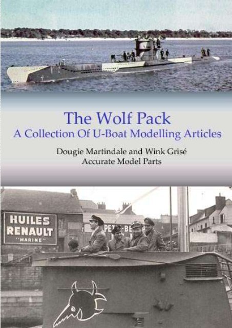
<strong>The</strong> <strong>Wolf</strong> <strong>Pack</strong><br />
<strong>The</strong> <strong>Wolf</strong> <strong>Pack</strong>: A Collection Of U-Boat <strong>Model</strong>ling Articles Page 1
Contents<br />
<strong>The</strong> <strong>Wolf</strong> <strong>Pack</strong><br />
Introduction<br />
Articles: Kriegsmarine U-Boat Colours & Markings<br />
Type VIIC Free-Flooding Vent Patterns<br />
Type VII U-Boat Modifications<br />
<strong>The</strong> Snorting Bull Insignia<br />
U 96 & <strong>The</strong> Laughing Sawfish<br />
German U-Boat Victory Pennants<br />
U-Boat <strong>Model</strong> Kits & Accessories<br />
Super-detailing Revell’s 1/72nd Type VIIC U-Boat*<br />
Revell Type VIIC Checklist<br />
Appendices: References<br />
Photo Sources<br />
Recommended Reading<br />
Index<br />
*Super-detailing Revell’s 1/72nd Type VIIC U-Boat by Wink Grisé<br />
All other articles by Dougie Martindale<br />
All text and drawings copyright © Dougie Martindale / Wink Grisé / <strong>Accurate</strong> <strong>Model</strong> <strong>Parts</strong>, 2010<br />
<strong>The</strong> <strong>Wolf</strong> <strong>Pack</strong>: A Collection Of U-Boat <strong>Model</strong>ling Articles Page 2
<strong>The</strong> <strong>Wolf</strong> <strong>Pack</strong><br />
Contents<br />
Introduction ............................................................................................. 7<br />
Induction ....................................................................................................................................................... 7<br />
A seminal release .......................................................................................................................................... 8<br />
<strong>The</strong> allure of the VIIC .................................................................................................................................. 9<br />
A growing collection ..................................................................................................................................... 9<br />
<strong>The</strong> <strong>Wolf</strong> <strong>Pack</strong> ............................................................................................................................................ 10<br />
<strong>The</strong> SubCommittee Report articles .......................................................................................................... 12<br />
Additional articles ...................................................................................................................................... 12<br />
Kriegsmarine U-Boat Colours & Markings ......................................... 13<br />
� Part I - Introduction ........................................................................................... 13<br />
� Part II – Difficulties In Determining U-Boat Colours ...................................... 13<br />
Documentation ............................................................................................................................................ 14<br />
Photographs ................................................................................................................................................ 14<br />
Paint Quality ............................................................................................................................................... 15<br />
Summary Of Identification Problems ...................................................................................................... 15<br />
� Part III - Standard Kriegsmarine Paints ............................................................ 16<br />
Hellgrau 50 .................................................................................................................................................. 19<br />
� Part IV - U-Boat Colours .................................................................................. 20<br />
Lower hull colours ...................................................................................................................................... 20<br />
Pre-war colours .......................................................................................................................................... 22<br />
Wartime upper greys ................................................................................................................................. 25<br />
� Part V - Camouflage ......................................................................................... 30<br />
Camouflage colours .................................................................................................................................... 32<br />
� Part VI - Insignia, Tonnage & Tactical Markings ............................................ 33<br />
Tactical markings ....................................................................................................................................... 36<br />
� Part VII - Miscellaneous Colours ..................................................................... 37<br />
Conning tower ............................................................................................................................................ 37<br />
Guns ............................................................................................................................................................. 40<br />
Hull .............................................................................................................................................................. 40<br />
Waterline draft markings .......................................................................................................................... 41<br />
Deck parts ................................................................................................................................................... 42<br />
� Part VIII - Wooden Deck .................................................................................. 42<br />
� Part IX - Weathering ......................................................................................... 44<br />
Weathering above the waterline ............................................................................................................... 44<br />
Weathering below the waterline ............................................................................................................... 46<br />
� Part XI – Acknowledgements & Useful Links ................................................. 50<br />
<strong>The</strong> <strong>Wolf</strong> <strong>Pack</strong>: A Collection Of U-Boat <strong>Model</strong>ling Articles Page 3
<strong>The</strong> <strong>Wolf</strong> <strong>Pack</strong><br />
Type VIIC Free-Flooding Vent Patterns .............................................. 51<br />
� Part I – Introduction .......................................................................................... 51<br />
� Part II – Free-Flooding Vents ........................................................................... 51<br />
Variations in vent patterns ........................................................................................................................ 51<br />
Main free-flooding vent patterns .............................................................................................................. 52<br />
Diesel exhaust outlets ................................................................................................................................. 55<br />
Medium-sized vents above central drainage area ................................................................................... 56<br />
Vents near torpedo doors........................................................................................................................... 58<br />
Two/three vents next to stem ..................................................................................................................... 59<br />
Twelve circular vents above torpedo doors .............................................................................................. 59<br />
Curved line of vents above central drainage area ................................................................................... 60<br />
Three vents at rear of saddle tanks ........................................................................................................... 62<br />
Vents behind forward hydroplanes .......................................................................................................... 62<br />
Vents near rear hydroplanes ..................................................................................................................... 62<br />
Vents aft of the rudders ............................................................................................................................. 63<br />
� Part III - Central Drainage Area ....................................................................... 64<br />
� Part IV - Type VII U-Boat Batches .................................................................. 66<br />
Type VII U-Boat Modifications ........................................................... 69<br />
� Part I - Introduction ........................................................................................... 69<br />
� Part II - Type VIIA & VIIB Modifications....................................................... 70<br />
Pre-war features ......................................................................................................................................... 70<br />
Early war VIIA and VIIB modifications .................................................................................................. 72<br />
VIIA and VIIB deck railings ..................................................................................................................... 76<br />
Differentiating between variants ............................................................................................................... 77<br />
� Part III – Early Type VIIC Modifications ........................................................ 78<br />
Air intake grills ........................................................................................................................................... 78<br />
Mast antenna housing ................................................................................................................................ 79<br />
Earliest VIIC features ................................................................................................................................ 80<br />
U 93 – U 98 .................................................................................................................................................. 85<br />
Attack periscope base ................................................................................................................................. 88<br />
Diesel exhaust outlets ................................................................................................................................. 88<br />
S-Gerät ......................................................................................................................................................... 88<br />
Early VIIC deck railings ............................................................................................................................ 89<br />
Other early VIIC modifications ................................................................................................................ 91<br />
Tower ........................................................................................................................................................... 92<br />
Deck ............................................................................................................................................................. 96<br />
Radar ......................................................................................................................................................... 101<br />
<strong>The</strong> <strong>Wolf</strong> <strong>Pack</strong>: A Collection Of U-Boat <strong>Model</strong>ling Articles Page 4
<strong>The</strong> <strong>Wolf</strong> <strong>Pack</strong><br />
Other mid-to-late war modifications ...................................................................................................... 102<br />
� Part V – Final Thoughts .................................................................................. 102<br />
Museum boat U 995 .................................................................................................................................. 102<br />
Suitability of the Revell kits ..................................................................................................................... 103<br />
<strong>The</strong> Snorting Bull Insignia.................................................................. 104<br />
� Part I - Original Bull Of Scapa Flow Insignia ................................................ 104<br />
� Part II - Snorting Bull On 7 th U-Flottille U-Boats .......................................... 106<br />
� Part III - <strong>The</strong> Laughing Cow Of Lorient......................................................... 111<br />
U 96 & <strong>The</strong> Laughing Sawfish ........................................................... 112<br />
� Part I - <strong>The</strong> Real U 96 ..................................................................................... 112<br />
� Part II - 9 th U-Flottille Sawfish ....................................................................... 114<br />
� Part III - Das Boot ........................................................................................... 115<br />
� Part IV – <strong>The</strong> Perennial Sawfish Colour Debate ............................................ 116<br />
� Part V – AMP Sawfish Decals ........................................................................ 117<br />
German U-Boat Victory Pennants ...................................................... 119<br />
� Part I - Merchant Ship Victory Pennants ........................................................ 119<br />
� Part II - Warship & Aircraft Victory Pennants ............................................... 122<br />
� Part III - Tonnage Figures ............................................................................... 122<br />
� Part IV - Commissioning Pennant .................................................................. 124<br />
� Part V - AMP Flag Range ............................................................................... 125<br />
U-Boat <strong>Model</strong> Kits & Accessories ..................................................... 127<br />
� Part I – Introduction ........................................................................................ 127<br />
� Part II – 1/32 nd to 1/60 th scale ......................................................................... 130<br />
� Part III –1/72 nd scale ....................................................................................... 132<br />
� Part IV – 1/96 th to 1/150 th scale ...................................................................... 135<br />
� Part V – 1/200 th to 1/700 th scale ...................................................................... 136<br />
� Part VI –Manufacturer & Supplier Websites .................................................. 139<br />
<strong>The</strong> <strong>Wolf</strong> <strong>Pack</strong>: A Collection Of U-Boat <strong>Model</strong>ling Articles Page 5
<strong>The</strong> <strong>Wolf</strong> <strong>Pack</strong><br />
Super-detailing Revell’s 1/72 nd Type VIIC U-Boat ........................... 141<br />
� Part I – U-Brass Project .................................................................................. 141<br />
� Part II – Choosing A Boat ............................................................................... 143<br />
� Part III – <strong>The</strong> Hull ........................................................................................... 143<br />
Bow ............................................................................................................................................................ 143<br />
Free-flooding vent holes ........................................................................................................................... 146<br />
Main hull ................................................................................................................................................... 147<br />
Stern .......................................................................................................................................................... 151<br />
� Part IV – <strong>The</strong> Deck ......................................................................................... 151<br />
Replacement decks ................................................................................................................................... 151<br />
Fitting the deck ......................................................................................................................................... 152<br />
Other deck parts ....................................................................................................................................... 152<br />
� Part V – <strong>The</strong> Tower ......................................................................................... 154<br />
Outside tower ............................................................................................................................................ 154<br />
Inside tower ............................................................................................................................................... 156<br />
Railings ...................................................................................................................................................... 159<br />
� Part VI – Painting & Weathering .................................................................... 161<br />
� Part VII –Decals .............................................................................................. 162<br />
Düsseldorf town crest ............................................................................................................................... 162<br />
� Part VIII – Finishing Touches ........................................................................ 163<br />
Kriegsmarine flag ..................................................................................................................................... 163<br />
Rigging ...................................................................................................................................................... 163<br />
Deck activity ............................................................................................................................................. 164<br />
Completed at last ...................................................................................................................................... 164<br />
Revell Type VIIC Checklist ............................................................... 166<br />
Appendix: References ......................................................................... 170<br />
Appendix: Photo Sources ................................................................... 172<br />
Appendix: Recommended Reading .................................................... 176<br />
Index.................................................................................................... 181<br />
<strong>The</strong> <strong>Wolf</strong> <strong>Pack</strong>: A Collection Of U-Boat <strong>Model</strong>ling Articles Page 6
M<br />
Introduction<br />
Introduction<br />
any of our <strong>Accurate</strong> <strong>Model</strong> <strong>Parts</strong> forum members were inducted into the realm of U-boat research<br />
in a similar fashion. Spread throughout the globe as we are, many of us came to study U-boats<br />
through the building of a model kit. In most cases this entrance came via Revell’s 1/72 nd Type VIIC Uboat<br />
(RV5015) model kit. Our common desire to correct and improve this particular model kit has<br />
advanced our understanding of the external characteristics of the Type VII by a great deal. <strong>The</strong> foremost<br />
conduit for our increased knowledge is the sharing of information via various internet forums. Yet the<br />
primary catalyst in the development of the U-boat modelling scene is arguably the Revell VIIC kit itself.<br />
<strong>The</strong> <strong>Wolf</strong> <strong>Pack</strong> is a collection of articles dealing with various issues pertaining to the U-boat<br />
modeller. Due to the impact of the aforementioned Revell kit, particular emphasis has been placed on<br />
covering issues that may be of interest to the modeller building this particular model kit. I have made no<br />
attempt to delve into a technical analysis; my points are intentionally limited in scope to those of<br />
specific interest to the U-boat modeller.<br />
I would like to thank my <strong>Accurate</strong> <strong>Model</strong> <strong>Parts</strong> colleague Wink Grisé for allowing me to include<br />
his U 557 build article in this collection.<br />
Induction<br />
My own induction to the world of U-boat models derived from an earlier model kit: Amati’s mixed<br />
media 1/72 nd scale U 47. I spent several months on what is generally regarded as a notoriously<br />
challenging build. <strong>The</strong> Amati kit took my modelling into new areas, allowing me to improve certain<br />
skills that were not being developed when I had been building simple injection-moulded kits. Having<br />
spent some rather pleasant evenings over-weathering the model, I began to wonder if the lovely red hull<br />
on my model was indeed historically accurate. Should the hull be red or dark grey? And did the real boat<br />
really have a thin black bootline? <strong>The</strong>se simple questions would divert me away from my usual 1/72 nd<br />
aircraft subjects on a completely new tangent. Indeed they were the genesis of this collection of articles.<br />
Rather than take to another aircraft model, I began researching the paint colours of the famous<br />
Type VIIB U-boat U 47. This lead to a work-in-progress article on U 47’s colours being published in the<br />
December 2003 (#55) issue of the SubCommittee Report (SCR). <strong>The</strong> SCR is a quarterly magazine<br />
published by the SubCommittee, a non-profit organisation who share an interest in submarines,<br />
primarily the building of radio-controlled submarine models.<br />
Although it may seem slightly implausible now, many modellers of a decade ago were opting for<br />
a red hull and a black bootline on their U-boat models. With very few exceptions, almost all modellers<br />
were painting their upper hulls with light grey paint. This practice continued despite the many photos in<br />
common circulation showing various shades of greys on the upper hull. <strong>The</strong>re was no real guidance on<br />
these matters, and it appeared that no researcher had analysed U-boat colours in any real depth.<br />
Following a request by the SubCommittee editor Jeff LaRue, I began researching an article on<br />
U-boat colours. Such an undertaking would not be complete without access to primary resources. By a<br />
stroke of good fortune, I was sent photocopies of several Kriegsmarine painting regulations by David E.<br />
Brown. Some have not, as yet, been published in English language books or the internet. With this<br />
primary material, and a growing mini-library of U-boat books, I was able to write Kriegsmarine U-Boat<br />
<strong>The</strong> <strong>Wolf</strong> <strong>Pack</strong>: A Collection Of U-Boat <strong>Model</strong>ling Articles Page 7
Introduction<br />
Colours & Markings. This three-part article was published in the September 2004 (#58), December<br />
2004 (#59) and March 2005 (#60) issues of the SubCommittee Report. <strong>The</strong> article is offered in this<br />
collection, albeit with different photos than were included in the original publication.<br />
In tandem with my research on U-boat colours, I continued to study U 47 in detail. This<br />
necessitated collecting as many photos of the boat as possible. Once I had collected over 200 photos of<br />
the real boat, multiple serious inaccuracies became apparent in the Amati kit. By analysing these photos,<br />
it also became obvious that certain external characteristics of the boat changed over time. Indeed I could<br />
not compare period photos to the Amati kit without first establishing when the photo had been taken.<br />
This analysis allowed me to appreciate how U 47 and other U-boats were modified over time. An article<br />
entitled Evolution Of A Type VII U-Boat: U-47 Modifications was published in a later SCR.<br />
While the modifications were directly linked to modelling, I began to branch out to other areas<br />
of my chosen boat. I began writing of the operational history of the U 47, the personal history of the<br />
serving officers, and the boat’s famous exploits in Scapa Flow. I also spent significant time on a number<br />
of side profiles, and also completed artwork for the various versions of the snorting bull insignia. This<br />
writing and artwork was far removed from my now-neglected hobby of aircraft modelling.<br />
<strong>The</strong> introduction of another model kit would keep me away from the table for longer still.<br />
A seminal release<br />
In late 2003, a significant development occurred with regard to U-boat modelling. Revell released an<br />
injected moulded 1/72 nd Type VIIC U-boat (RV5015) model kit. When the first photos of an unpainted<br />
model appeared on Revell’s website, we could all see that this modern kit was equal in quality and<br />
accuracy to many contemporary releases.<br />
<strong>The</strong> general consensus of opinion on the new kit was very positive, there being genuine<br />
excitement at the prospect of building the boat. <strong>The</strong> pointed bow, the rivets, the doublers – they all<br />
looked amazing. But it soon became apparent that the kit did have certain faults: the smaller free<br />
flooding holes had been replicated with rectangles rather than ovals; and the length of the torpedo doors<br />
gave an appearance that did not look quite right. In time a more involved evaluation would reveal more<br />
errors.<br />
<strong>Model</strong>lers who were used to very accurate kits were occasionally disparaging about certain<br />
features of the Revell U-boat. <strong>The</strong>se modellers tended to have come to the subject after the release of<br />
this seminal kit. Using the Revell kit as their baseline, they were less forgiving of its errors. By way of<br />
comparison, modellers who had struggled to fix the multiple fallibilities of the now redundant Amati kit,<br />
or who had tried in vain to improve the old 1/125 th scale Revell U-boat kits, had a more positive<br />
outlook. <strong>The</strong>y appreciated that the new Revell kit was a state of the art masterpiece when compared to<br />
the predecessors. <strong>The</strong> most important factor was that Revell had managed to successfully replicate the<br />
clean aesthetic curves of the Type VIIC. Even an out-of-box build looked like a VIIC. At long last we<br />
had an affordable and reasonably accurate VII model to work with.<br />
<strong>The</strong> potential of the near metre long kit was obvious. <strong>The</strong> scale allowed a level of detail that<br />
cannot be considered in 1/350 th or 1/144 th scales. But the central asset of the kit was the wonderful looks<br />
of the Type VIIC itself. <strong>The</strong> visual impact of a VIIC of this size enticed many modellers away from their<br />
usual armour and aircraft subjects and into the sphere of the U-boat. It was also obvious that aftermarket<br />
companies would swarm around this kit, releasing brass and resin sets for a market full of new U-boat<br />
enthusiasts. In the early months of 2004, everyone looked intently for the release of aftermarket sets.<br />
<strong>The</strong> demand for a replacement deck was satisfied by <strong>Model</strong>brass and Nautilus. White Ensign and<br />
Eduard released their sets to the approval of us all. Yet once the main aftermarket companies had<br />
released their sets, it became apparent that a few aspects had not been addressed. For example, the overlong<br />
torpedo doors and the free-flooding patterns could not be easily rectified without suitable photoetch<br />
pieces.<br />
<strong>The</strong> <strong>Wolf</strong> <strong>Pack</strong>: A Collection Of U-Boat <strong>Model</strong>ling Articles Page 8
Introduction<br />
To highlight these issues, I penned an article entitled Type VIIC Free-Flooding Vent Patterns for<br />
SCR#62. An updated version of this article can be found in this collection. Following this article I was<br />
contacted by Wink Grisé, a modeller who was researching U-boat material for his U 557 build. In our<br />
discussions we decided that no aftermarket company would release a set to correct the free-flooding<br />
inaccuracies in the Revell kit. Together we had the research knowledge and photo-etch design skills to<br />
produce such a set. So we teamed up to design the product, releasing it under the name U-Brass.<br />
<strong>The</strong> allure of the VIIC<br />
While the Amati kit had taken my modelling in a different direction – to writing articles rather than just<br />
sticking my grubby fingers together – the Revell kit had taken me into the realm of co-designing<br />
aftermarket sets. <strong>The</strong> Revell kit was also the catalyst for researching the entire class of Type VIICs.<br />
With a subject field of hundreds of boats, this area of research was far more expansive.<br />
<strong>The</strong>re was one pivotal factor that allows the VIIC enthusiast endless scope for research: the boats<br />
were constantly modified in an attempt to meet evolving technological requirements. Throughout the<br />
course of the war, older equipment was replaced by more sophisticated kit. As a result, each of the<br />
VIICs and VIIC/41s had different features over time. For example, U 93 may have originally shared<br />
very similar features to U 94. Yet there would be small differences between the two boats, and these<br />
differences would appear at slightly different time periods. <strong>The</strong> boats themselves would also change<br />
over time with respect to paint colours and insignia. Almost every boat was therefore unique.<br />
When we consider that there were roughly seven hundred boats in the Type VII class, that most<br />
of the boats were different in some respect to others, and that many had interesting operational careers,<br />
the modeller is therefore presented with a near endless supply of choices. It is this facet of U-boat<br />
modelling that can be very alluring. <strong>The</strong> multitude of possibilities allow the modeller a wealth of<br />
choices: there is always another boat to model, with dissimilar features to portray. Even after years of<br />
study, a new photograph will reveal a new insignia or different technical feature.<br />
Yet these very same factors may be construed as a nightmare for the novice modeller. <strong>The</strong><br />
initiate is beset with obvious difficulties: how on earth can they build an accurate replica when there is<br />
so much variation? With only a few books at their disposal, how can the modeller possibly learn about<br />
all the modifications? And how are they supposed to know when the relevant modifications were made<br />
to their chosen boat? <strong>The</strong>y may find a few photos of their chosen boat but these photos will only provide<br />
clues on certain features. <strong>The</strong>y may have three photos but each photo may be taken a year apart, leading<br />
to puzzlement as to why the same boat has different features, different paint schemes and even different<br />
insignia.<br />
This scenario may be seen in a different light depending on the disposition of the modeller. If<br />
they wish to spend the majority of their free time at the modelling table, the modeller will be best served<br />
by conducting an out-of-the-box build. However, if they are more patient and inquisitive type, who is<br />
content to communicate on internet forums, to collect books and examine them with a magnifying glass,<br />
and to expend years rather than months on any given subject, modelling the Type VIIC can become an<br />
engrossing pastime.<br />
A growing collection<br />
In any true super detailing project, the modeller will need to be armed with a range of modelling<br />
products and the expertise to use them. Yet just as important to the project is knowledge. Without a<br />
detailed appreciation of the subject garnered through research, the super detailer will not be equipped<br />
with enough knowledge to achieve their full potential.<br />
I was acutely conscious of the complications associated with amassing research material on the<br />
VIIC. Even with a dozen books, the modeller will find enormous difficulty in assessing how their<br />
chosen boat was modified and what features were present at a given time. No one book was available to<br />
<strong>The</strong> <strong>Wolf</strong> <strong>Pack</strong>: A Collection Of U-Boat <strong>Model</strong>ling Articles Page 9
Introduction<br />
help answer these questions. To begin to address this subject I started to write a summary exploration of<br />
the subject. Due to other commitments the resulting article - Type VII U-Boat Modifications – would<br />
take three years to complete. Constantly aware that my target audience was the modeller of the Revell<br />
VIIC and VIIC/41 kits, I took care not to diversify to technical considerations.<br />
When I began writing this article, I had been frustrated by the lack of an ideal conduit with<br />
which to share the information. Yet this predicament was solved when Wink and I team up again, this<br />
time as <strong>Accurate</strong> <strong>Model</strong> <strong>Parts</strong>. With the formation of our own website it was possible to release our own<br />
articles as downloadable pdf files. This fitted our philosophy of helping other modellers, by releasing<br />
products and sharing our research information.<br />
In the AMP library section we added Kriegsmarine U-Boat Colours & Markings and an updated<br />
version of Type VIIC Free-Flooding Vent Patterns. In the USN SUBS section of the library, articles<br />
aimed at assisting the Gato modellers were prepared by Wink and others. Wink also created the AMP<br />
forum to allow like-minded submarine model-makers the opportunity to freely share information.<br />
Now that we had a library section to release articles, and a forum in which the subjects could be<br />
discussed, I was free to pen other articles. I modified an existing U 47 insignia article to a new generic<br />
version entitled <strong>The</strong> Snorting Bull Insignia. Knowing the interest in the sawfish insignia I then wrote<br />
<strong>The</strong> Laughing Sawfish. This short article discusses the debatable points regarding sawfish colours but<br />
does not offer any resolutions.<br />
In the winter of 2008/2009, Wink and I decided to add U-boat victory pennants to our range of<br />
flags. It became apparent that some of our pennant customers would need guidance on the subject. An<br />
article entitled German U-Boat Victory Pennants was our method of addressing this issue. At some<br />
point in 2009 I finally found the time to complete the article Type VII U-Boat Modifications and release<br />
it on the AMP library section. With various ongoing commitments I had envisaged this to be my last<br />
article for the U-boat modeller. Yet almost by accident I penned U-Boat <strong>Model</strong> Kits & Accessories<br />
during a festive break. Starting as a brief list of accessories for the Revell VIIC kit, it somehow became<br />
a tabular list of U-boat model kits and accessories for all scales.<br />
Upon completion of U-Boat <strong>Model</strong> Kits & Accessories, there were now seven downloadable pdf<br />
articles in the series. Rather than seven distinct downloads it seemed worthwhile to amalgamate them all<br />
into one downloadable file. <strong>The</strong> incorporation of a table of contents and an index would allow for<br />
improved searching functionality. Now that the articles were being collated, I decided to tie up a few<br />
loose ends. I listed the known inaccuracies and issues in the Revell VIIC kit in the appendix entitled<br />
Revell Type VIIC Checklist. To assist the modeller who is navigating the early steps of research, who<br />
has no idea which books to purchase, I listed the books that have been of benefit to me in the appendix<br />
Recommended Reading. <strong>The</strong> last inclusion was Wink’s U 557 build article Super-detailing Revell’s<br />
1/72nd Type VIIC U-Boat. I am grateful to Wink for allowing this to be included as it acts as the final<br />
piece in the jigsaw.<br />
<strong>The</strong> <strong>Wolf</strong> <strong>Pack</strong><br />
In recent years the full potential of the Revell kit has been realised. Armed with aftermarket sets and<br />
research material, several modellers have utilised their considerable talents to produce extremely<br />
accurate models. <strong>The</strong> blogs and online posts of these very skilled modellers allow others to follow in<br />
their footsteps.<br />
<strong>The</strong> purpose of this collection is to equip modellers of all levels with some of the research tools<br />
needed to complete an accurate VIIC model. I hope that it may act as a starting point for further<br />
discussion by other modellers on our forum. If skilled modellers and researchers continue to share<br />
resources via this medium, our combined knowledge will inevitably lead to a better understanding of<br />
this fascinating subject.<br />
Dougie Martindale, May 2010<br />
<strong>The</strong> <strong>Wolf</strong> <strong>Pack</strong>: A Collection Of U-Boat <strong>Model</strong>ling Articles Page 10
Spanish translation<br />
Introduction<br />
Five of the articles contained in this collection can be found in Spanish at http://www.u-historia.com/<br />
<strong>The</strong> articles can be found by following the section and subsection hyperlinks listed below.<br />
Kriegsmarine U-Boat Colours & Markings<br />
� Spanish title Colores y símbolos de los Uboot<br />
� Website section Técnica<br />
� Subsection Artículos Históricos<br />
� Translators and collaborators Felipe Carmona Hernández, Guillermo Martínez, Alonso<br />
Espinosa, Dani J.Åkerberg, Francisco Pérez de Nanclares,<br />
José Carlos Violat, Ombretta Lotti y Alejandra Lifischtz<br />
Type VIIC Free-Flooding Vent Patterns (original version)<br />
� Spanish title Patrones de los agujeros de inundación libre de los Tipo<br />
VIIc<br />
� Website section Técnica<br />
� Subsection Artículos Históricos<br />
� Translator Dani J.Åkerberg<br />
Type VII U-Boat Modifications<br />
� Spanish title Modificaciones externas en los uboot del Tipo VII<br />
� Website section Técnica<br />
� Subsection Artículos Históricos<br />
� Translator Dani J.Åkerberg<br />
<strong>The</strong> Snorting Bull Insignia<br />
� Spanish title El emblema del "Toro resoplando"<br />
� Website section Historia<br />
� Subsection Artículos Históricos<br />
� Translator Dani J.Åkerberg<br />
<strong>The</strong> Laughing Sawfish<br />
� Spanish title El U96 y el "Pez sierra sonriente"<br />
� Website section Historia<br />
� Subsection Artículos Históricos<br />
� Translator Dani J.Åkerberg<br />
<strong>The</strong> <strong>Wolf</strong> <strong>Pack</strong>: A Collection Of U-Boat <strong>Model</strong>ling Articles Page 11
<strong>The</strong> SubCommittee Report articles<br />
Introduction<br />
<strong>The</strong> SubCommittee Report (SCR) is a quarterly magazine published by the SubCommittee, a non-profit<br />
organisation who share an interest in submarines, primarily the building of radio-controlled submarine<br />
models. <strong>The</strong>ir website can be found at http://www.subcommittee.com/<br />
U-boat Color Schemes*<br />
� December 2003 (#55) SubCommittee Report<br />
* This article is a very early discussion of U 47 paint colours<br />
Kriegsmarine U-Boat Colours & Markings<br />
� September 2004 (#58), December 2004 (#59) and March 2005 (#60) SubCommittee Report<br />
Type VIIC Free-Flooding Vent Patterns<br />
� September 2005 (#62) SubCommittee Report<br />
Evolution Of A Type VII U-Boat: U-47 Modifications*<br />
� March 2006 (#64) SubCommittee Report<br />
* This article discusses modifications only<br />
Additional articles<br />
U 47 Modifications & Colours<br />
� http://www.modelshipwrights.com<br />
Follow the following hyperlinks:<br />
� Features<br />
� Ship Articles By Class<br />
� Submarines<br />
� Reference<br />
� U 47 Modifications & Colours<br />
<strong>The</strong> <strong>Wolf</strong> <strong>Pack</strong>: A Collection Of U-Boat <strong>Model</strong>ling Articles Page 12
Contents<br />
Kriegsmarine U-Boat Colours & Markings<br />
Kriegsmarine U-Boat Colours & Markings<br />
Part I Introduction<br />
Part II Difficulties In Determining U-Boat Colours<br />
Part III Standard Kriegsmarine Paints<br />
Part IV U-Boat Colours<br />
Part V Camouflage<br />
Part VI Insignia, Tonnage & Tactical Markings<br />
Part VI Miscellaneous Colours<br />
Part VIII Wooden Deck<br />
Part IX Weathering<br />
Part X Interior & Summary<br />
Part XI Acknowledgements & Useful Links<br />
Part I - Introduction<br />
T<br />
he following article attempts to provide a general guide to the colours used upon the German Uboats<br />
of the Second World War. It was published complete with 51 black and white photographs in<br />
the September 2004 (#58), December 2004 (#59) and March 2005 (#60) issues of the SubCommittee<br />
Report.<br />
In the course of researching this article, two editions (November 1941 and July 1944) of<br />
Allgemeinen Baubestimmungen (Building Regulations Order) Nr. 31 - a detailed painting regulation<br />
which specified the paints that were to be applied to Kriegsmarine vessels - were kindly sent to me by<br />
David E. Brown. Primary data was gleamed wherever possible from these editions, and the U-boat<br />
section of the March 1940 edition, of this regulation. I endeavoured to find more primary sources by<br />
requesting copies of other regulations from the Bundesarchiv, but my request did not bear fruit. I also<br />
corresponded with gentlemen from the RAL Institute, Snyder & Short Enterprises and authors who have<br />
published material in relation to Kriegsmarine paint colours. Discussions on U-boat colours with many<br />
modellers and enthusiasts via email and internet forums also proved to be informative. <strong>The</strong> gentlemen to<br />
whom I am particularly obliged are listed in the acknowledgements section.<br />
Part II – Difficulties In Determining U-Boat Colours<br />
S<br />
everal combined factors hinder the investigation of the colours used upon Kriegsmarine U-boats,<br />
and prevent a resolution to fundamental questions such as the exact colour of standard Kriegsmarine<br />
<strong>The</strong> <strong>Wolf</strong> <strong>Pack</strong>: A Collection Of U-Boat <strong>Model</strong>ling Articles Page 13
Kriegsmarine U-Boat Colours & Markings<br />
paints. Although many of the same factors are present in the assessment of Luftwaffe colours, this<br />
subject has at least been resolved to a level which satisfies most modellers and Luftwaffe enthusiasts.<br />
<strong>The</strong> same cannot be said of the colours used upon the German U-boats of World War II.<br />
Documentation<br />
Many of the documents and regulations which would have been of help to us in analysing Kriegsmarine<br />
colours were destroyed by Allied bombing. Still more were deliberately destroyed at the end of the war.<br />
Luckily some material was captured by the Allies, and so survived. <strong>The</strong>se were gradually returned to<br />
Germany over a period of time. <strong>The</strong> documents included Allgemeinen Baubestimmungen (Building<br />
Regulations Order) Nr. 31, a detailed painting regulation which specified the paints that were to be<br />
applied to Kriegsmarine vessels. Also included were three colour cards - TL-F1 to TL-F3 - which had<br />
been in use at the Wilhelmshaven shipyards in 1944. Though these colour cards are a great help, it is not<br />
possible to precisely reproduce the colour of the Kriegsmarine paints used upon World War II U-boats<br />
from them since the colour cards have changed in the many years since they were produced.<br />
On the colour cards and the 1944 edition of Nr. 31, the colour of the Kriegsmarine paints were<br />
cross-referenced to the nearest RAL codes. <strong>The</strong> Reichsausschuss für Lieferbedingungen - RAL -<br />
(Committee of the German Reich for Terms and Conditions of Sale) had been founded by the private<br />
sector and the German government in 1925. RAL’s original task had been to standardise precise<br />
technical terms of delivery and sale of colours for the purpose of rationalisation. <strong>The</strong> initial range of 40<br />
RAL colours was introduced in 1927, many years after the First World War Imperial High Seas Fleet<br />
had been using Hellgrau 50 and other German naval paints on their battleships. <strong>The</strong>se same German<br />
naval paints were used in the Second World War Kriegsmarine. As the German naval paints pre-dated<br />
the foundation of the RAL, it follows that these paints cannot have had an exact RAL equivalent. <strong>The</strong><br />
RAL codes that were cross-referenced to the German naval paints in the painting regulations were the<br />
closest match to them rather than a direct match.<br />
By the late 1930s, the RAL Register numbered more than 100 shades. In 1939 and 1940 the<br />
Register was revised, and re-named RAL 840R (R = revised). This colour collection was re-examined in<br />
1953, when many colours were scrapped. <strong>The</strong> scrapped colours included those which had been in<br />
military use in the Third Reich. A further review took place in 1961 and again in 1976, when an<br />
internationally used colour measurement system was laid down. Due to environmental issues, certain<br />
pigments in use in the 1940s are not allowed to be used today. Pigments are unique, and although RAL<br />
tried to obtain the best match for their older colours, certain slight colour changes between today’s RAL<br />
colours and those of the 1940s are inevitable. This, for us, equates to a further variance between the<br />
colour of the Kriegsmarine paints and today’s RAL colours.<br />
Photographs<br />
<strong>The</strong> assessment of vintage colour photos of Kriegsmarine U-boats is fraught with difficulties. <strong>The</strong> more<br />
primitive technology involved in colour photography of the 30’s and 40’s means that they were not even<br />
reliable documents when they were taken. <strong>The</strong>y have also suffered with age during the sixty years that<br />
have passed since they were taken. Even modern colour photography has its traps. <strong>The</strong> same scene taken<br />
with the same camera under the same lighting conditions but with film from different manufacturers can<br />
produce different results. Some films can produce a green tone, whereas others can produce a blue tone.<br />
<strong>The</strong> colour film used in Germany during WWII, developed by Agfa, tended to produce a blue tone. It is<br />
also possible that some of these “colour” photographs may be black and white photos that have been<br />
coloured by hand.<br />
Though there are many black and white photographs available to us, determining colour shades<br />
from them is not possible. Variances in the light conditions when the photograph was taken, the<br />
different types of film used, the exposure of the photo, and the variations in printing methods all make<br />
<strong>The</strong> <strong>Wolf</strong> <strong>Pack</strong>: A Collection Of U-Boat <strong>Model</strong>ling Articles Page 14
Kriegsmarine U-Boat Colours & Markings<br />
this exercise problematic. For those photos that are viewed on a computer, extra problems present<br />
themselves. <strong>The</strong> settings that were in place during the scanning process, the software used to view the<br />
photo and the monitor settings can all alter the colours.<br />
Paint Quality<br />
Due to the different ingredients, binders and production methods used, the colour reproduction of an<br />
established shade during the 30’s and 40’s did not have the quality we expect today. German paints<br />
during this period were commonly mixed with local pigments, and emphasised durability and chemical<br />
resistance over colour fidelity. Paint includes binders, solvents, colours (pigments and fillers) and<br />
additives, and variances occur according to how these ingredients are mixed, and how paint is applied.<br />
U-boats were needed at sea, and time spent in shipyards and harbours was minimal. <strong>The</strong> obvious<br />
conclusion is that during hasty refits paints would not always be mixed or applied according to<br />
established procedures. Such common practices as the regulation thinning might be overlooked, thus<br />
causing the resulting paint to vary in colour. Shipyards would only have been given a rough guide to the<br />
standard colour, which they would replicate with what colours were available to them at the time.<br />
Obtaining a colour match was of far less importance than protecting against corrosion, which was the<br />
primary reason for applying paint.<br />
Another troublesome problem lies with the shortages incurred due to wartime conditions. <strong>The</strong>se<br />
shortages, which became more acute as the war progressed, limited the choice of colours available.<br />
Though standard colours were often used during the early stages of the war, painting became less<br />
and less of a priority as the war progressed. By 1943, the Kriegsmarine had far more pressing matters to<br />
attend to than maintaining a consistent paint scheme throughout its U-boat fleet. Given that the paint<br />
itself changed in appearance as the U-boat became weathered, the greys seen upon late-war U-boats<br />
would have varied so much that it might not appear as if the colours used on these U-boats were<br />
standardised at all.<br />
<strong>The</strong> supply problems are evidenced in the 1944 painting regulations, which called for the<br />
greatest possible savings with respect to painting. Painting was only done where necessary at that time;<br />
it was not to be done merely to keep vessels looking pretty. <strong>The</strong> regulations also stated that when paint<br />
must be applied, it should be done at the smallest possible expenditure in terms of materials and work.<br />
<strong>The</strong> July 1944 painting regulations lifted the mixing prohibition, which had banned the mixing of<br />
batches of different coloured paints. <strong>The</strong>y also called for the top coat of paint, relevant for appearance<br />
only, to be reduced from two coats to one. This affected the transition from a dark colour to a light<br />
colour, as the darker colour would show through from underneath.<br />
Summary Of Identification Problems<br />
When the above problems have been taken into account, it follows that a scientifically precise<br />
reproduction of the colours used upon the U-boat fleet is impossible today. Adherence to RAL or<br />
Federal Standard codes is neither practical, nor necessary, and modellers have a large tolerance when<br />
selecting the colours to use on their models.<br />
However, even though we can’t accurately reproduce these colours, we do know roughly what<br />
colour each Kriegsmarine paint should have been under ideal conditions. If a variety of photographs<br />
taken under different lighting conditions of a particular U-boat are available to us, then we may be able<br />
to guess which Kriegsmarine paint was used upon this U-boat. <strong>The</strong> modeller or enthusiast who has<br />
studied Kriegsmarine paint colours is naturally better prepared to make an educated guess. This highly<br />
subjective, and often frustrating, exercise often does not yield any definitive answers. Once the modeller<br />
has guessed (for it is a matter of guesswork) which Kriegsmarine paint may have been used, I suggest<br />
that they should choose a colour close to the appropriate RAL code for that Kriegsmarine paint.<br />
<strong>The</strong> <strong>Wolf</strong> <strong>Pack</strong>: A Collection Of U-Boat <strong>Model</strong>ling Articles Page 15
Kriegsmarine U-Boat Colours & Markings<br />
Part III - Standard Kriegsmarine Paints<br />
T<br />
he list below includes most of the Kriegsmarine paints that were used<br />
upon the U-boat fleet. <strong>The</strong> number after the name is the DKM (Deutsche<br />
Kriegsmarine) designation.<br />
Hellgrau 50 (RAL7001)<br />
� This light grey, also called Silbergrau (silver grey) or Hellgrau 4,<br />
was used upon the superstructures of pre-and early-war surface<br />
vessels.<br />
Dunkelgrau 51 (RAL7000)<br />
� Even though Dunkelgrau means “dark grey”, this was a medium<br />
blue-grey. It has been referred to as Fehgrau (squirrel grey) and<br />
Dunkelgrau 3. It was used upon the upper hull sides of pre-and<br />
early-war surface vessels.<br />
Dunkelgrau 52 (RAL7024)<br />
� This dark neutral grey was a little lighter than Schiffsbodenfarbe<br />
III Grau. It has also been referred to as Graphitgrau (graphite<br />
grey) and Dunkelgrau 2.<br />
Dunkelgrau 53 (RAL7016)<br />
� This paint was the same colour as Schiffsbodenfarbe III Grau, but<br />
did not contain any anti-fouling ingredients. It has also been<br />
referred to as Anthrazitgrau (anthracite grey) and Dunkelgrau 1.<br />
Above: <strong>The</strong> names of<br />
Kriegsmarine paints<br />
were, not surprisingly,<br />
in German. <strong>The</strong><br />
translations above will<br />
help those of us who<br />
are unfamiliar with<br />
this language.<br />
Schiffsbodenfarbe III Grau (RAL7016)<br />
� <strong>The</strong> DKM number for this very dark grey anti-fouling paint was 23a and 23b. It was also<br />
known as Wasserlinienfarbe W.L. III Grau and Anthrazitgrau (anthracite grey). This was the<br />
same colour (RAL7016) as Dunkelgrau 53/Dunkelgrau 1, but included anti-fouling<br />
ingredients in the paint.<br />
<strong>The</strong> following three petrol-proof camouflage paints had no RAL equivalent codes given in the<br />
painting regulations.<br />
Schlickgrau 58<br />
� Schlickgrau, which means “mud-grey”, was a medium to dark grey with a hint of green.<br />
Blaugrau 58/1<br />
� A medium to dark grey with a hint of blue.<br />
Blauschwarz 58/2<br />
� A very dark blue.<br />
German<br />
colour<br />
terms<br />
German English<br />
Grau Grey<br />
Grün Green<br />
Blau Blue<br />
Braun Brown<br />
Oliv Olive<br />
Weiß White<br />
Rot Red<br />
Schwarz Black<br />
Schlick Mud<br />
Hell Light<br />
Mittel Medium<br />
Dunkel Dark<br />
Suitable paints for these colours are included in the table below. <strong>The</strong> Colourcoats range was<br />
produced by John Snyder of White Ensign <strong>Model</strong>s (http://whiteensignmodels.com). As he participated<br />
in producing the Snyder & Short Enterprises paint chip cards, the Colourcoats paints correspond directly<br />
to the Snyder & Short paint chips.<br />
<strong>The</strong> <strong>Wolf</strong> <strong>Pack</strong>: A Collection Of U-Boat <strong>Model</strong>ling Articles Page 16
Hellgrau<br />
50<br />
Kriegsmarine U-Boat Colours & Markings<br />
Paint, RAL and Federal Standard matches for Kriegsmarine paints<br />
Hellgrau<br />
50<br />
(alt)<br />
Dunkel-<br />
grau<br />
51<br />
Colour Light grey Light grey Medium<br />
blue-grey<br />
RAL<br />
code<br />
Nearest<br />
FS code<br />
Dunkel-<br />
grau<br />
52<br />
Dark<br />
grey<br />
Schiffsbod-<br />
enfarbe<br />
111 Grau<br />
Schlick-<br />
grau<br />
<strong>The</strong> <strong>Wolf</strong> <strong>Pack</strong>: A Collection Of U-Boat <strong>Model</strong>ling Articles Page 17<br />
58<br />
Dark grey Mediumto-dark<br />
grey with<br />
green<br />
Blaugrau<br />
58/1<br />
Mediumto-dark<br />
grey with<br />
blue<br />
7001 7038 7000 7024 7016 - - -<br />
36375 36492 35237 36076 In between<br />
36076 and<br />
35042<br />
Slightly<br />
darker<br />
than<br />
36134<br />
Darker<br />
than<br />
36152<br />
Blau-<br />
schwarz<br />
58/2<br />
Blue-<br />
black<br />
35044<br />
Colourcoats<br />
KM01 KM13 KM02 (*) KM06 KM05 KM11 KM12 -<br />
JPS 91-004 - 91-003 91-002 91-001 91-029 91-030 91-031<br />
Xtracolor X255 X221 X126 - X802 - X254 -<br />
(RAL7001) (RLM<br />
(RAL7016)<br />
X136 63)<br />
X128<br />
(FS16375)<br />
(FS16076)<br />
Humbrol 127 147 or 166 145 67 123 78 + 31 79 15 ($)<br />
Revell 374 76 (£) 57 (£) 74 78 47 77 350 ($)<br />
Testors’ MM1728 - MM1721 - MM2101 - - -<br />
<strong>Model</strong>-<br />
Master<br />
(FS36375)<br />
(FS35237) (RAL7016)<br />
* too much blue £ add white $ add black<br />
NB. <strong>The</strong> Federal Standard codes are only the nearest codes to the RAL codes, which are themselves<br />
only cross-references to the original Kriegsmarine paints. It must again be stated that adherence to the<br />
RAL or Federal Standard codes are not necessary by modellers. Dunkelgrau 51, etc. were paints, not<br />
colours, and thus varied to a degree in colour.<br />
<strong>The</strong> variation in colour between the Dunkelgrau<br />
51 paint used by one yard to that of another yard<br />
was much greater than we would expect today.<br />
<strong>The</strong> weathering suffered by a U-boat would<br />
further alter the colour. <strong>The</strong> “Hellgrau 50<br />
(alternative)” colour is explained later in the<br />
Hellgrau 50 section.<br />
I have been unable to ascertain whether<br />
the other Kriegsmarine colours in the table to<br />
the right were ever used on U-boats. <strong>The</strong>se<br />
colours were specified in the November 1941<br />
painting regulations.<br />
<strong>The</strong>re were also three “Norwegian” colours which were based on Korvettenkapitän Dechend’s<br />
1942 memorandum. Again, I have not been able to determine whether they were ever used upon Uboats.<br />
<strong>The</strong>se were –<br />
Dunkelblaugrau (dark blue grey, FS35044)<br />
Other Kriegsmarine colours<br />
Number Paint name Colour<br />
31/1 Hellgrau Light grey<br />
31/2 Dunkelgrau Dark grey<br />
32/1 Hellgrün Light green<br />
32/2 Dunkelgrün Dark green<br />
32/3 Olivgrün Olive green<br />
32/4 Hellbraun Light brown<br />
32/5 Dunkelbraun Dark brown<br />
32/6 Rosa Pink<br />
32/7 Blau Blue
Kriegsmarine U-Boat Colours & Markings<br />
Mittelblaugrau (medium blue grey, FS35240)<br />
Hellblaugrau (light blue grey, FS35488)<br />
Above: <strong>The</strong> colours in the guide above are based upon the RGB (red, green, blue) values of the RAL colours.<br />
<strong>The</strong>se values were obtained from a diskette purchased from Multicolor UK Ltd., RAL’s sales partner in the<br />
UK. For the Kriegsmarine colours which had no RAL code associated with them (the bottom three), the<br />
colours were matched as best as possible from the two-part set of Kriegsmarine paint chip cards produced by<br />
Snyder & Short Enterprises. Note that variances will occur due to monitor settings.<br />
Kriegsmarine colours can be found in the two-part set of paint chip cards produced by Snyder &<br />
Short Enterprises. <strong>The</strong>se are the best reproductions of the colours of the Kriegsmarine paints that are<br />
available to us at present. <strong>The</strong> cards, available from http://www.shipcamouflage.com/ and<br />
http://whiteensignmodels.com, include actual paint chips rather than printed inks. <strong>The</strong>y were produced<br />
from research materials generated by Flak Pletscher, the authors Dieter Jung, Arno Abendroth and<br />
Norbert Kelling and their book Anstriche und Tarnanstriche der deustschen Kriegsmarine (Painting and<br />
Camouflage of the German Navy) Second Edition (Bernard & Graefe Verlag, 1997), and archival chips<br />
and material sent to the RAL Institute. <strong>The</strong> latter material had been in use by the Kriegsmarinewerft<br />
Wilhelmshaven shipyard in 1944. <strong>The</strong> colours in the above book were based on an examination of<br />
colour cards that were returned to Germany by the Russians in the 1990s.<br />
<strong>The</strong> <strong>Wolf</strong> <strong>Pack</strong>: A Collection Of U-Boat <strong>Model</strong>ling Articles Page 18
Hellgrau 50<br />
Kriegsmarine U-Boat Colours & Markings<br />
In the many available photos of pre- and early-war Kriegsmarine battleships, there is often quite a<br />
contrast between the light grey Hellgrau 50 paint used on the superstructures and the medium blue-grey<br />
Dunkelgrau 51 paint used upon the upper hull sides. This contrast is usually greater than the contrast<br />
between RAL7001 and RAL7000, the RAL codes assigned to these paints in the 1940s. In addition, the<br />
light grey Hellgrau 50 looks almost white in photos where direct sunlight is present, and reports from<br />
early in the war noted that the light grey<br />
superstructure shined almost white in bright<br />
weather conditions. <strong>The</strong>se points have caused<br />
me to wonder if the Hellgrau 50 paint was<br />
actually quite a bit lighter than the RAL7001<br />
colour assigned to it. It should be noted that<br />
others who have studied Kriegsmarine<br />
colours have, independently of myself, come<br />
to ponder this same question.<br />
During 1941 ships such as the<br />
Bismarck, the Prinz Eugen and the Lützow<br />
appeared in “Baltic stripes” camouflage.<br />
<strong>The</strong>se ships had black and white stripes<br />
painted over their Hellgrau 50 superstructures<br />
and Dunkelgrau 51 upper hulls, plus dark grey<br />
areas at their bows and sterns. <strong>The</strong> S&S paint<br />
chip cards have separate chips for the colours<br />
used in this Baltic scheme. <strong>The</strong>y are so much<br />
lighter than the normal 50/51 colours that I<br />
originally assumed that paints with completely<br />
Above (A1): This 1940 colour photo of the mighty<br />
Kriegsmarine battleship Bismarck is useful to us because<br />
the paint regulations specify the paint colours we see before<br />
us. <strong>The</strong> hull is Dunkelgrau 51 and the superstructure –<br />
looking very light under the shining sun – is Hellgrau 50.<br />
<strong>The</strong> bootline just above the water is not black but the dark<br />
grey Wasserlinienfarbe W.L. III Grau. This paint has the<br />
same number, 23b, as the paint used on the lower hulls of<br />
U-boats, Schiffsbodenfarbe III Grau. <strong>The</strong>y are in fact the<br />
same paint, with the same colour (RAL7016), merely with<br />
different names.<br />
different Kriegsmarine codes had been used. I came to learn,<br />
somewhat frustratingly, that Hellgrau 50 and Dunkelgrau 51<br />
were used in this Baltic scheme, but that the colour of the<br />
Hellgrau 50 and Dunkelgrau 51 paints used in the Baltic<br />
scheme varied from the RAL7001 and RAL7000 codes<br />
normally associated with these Kriegsmarine paints.<br />
<strong>The</strong> basis for the “Baltic” colours in the S&S paint<br />
Left (A2): Comparisons between the Bismarck photo and this 1942<br />
photo, also taken in strong sunlight, show similarities between<br />
paint colours. <strong>The</strong> medium blue-grey colour on the boat on the<br />
front right (U 335), and on the VII and IX (U 163) in the second<br />
row, is similar to the Dunkelgrau 51 hull of the Bismarck. <strong>The</strong><br />
light grey on the camouflaged U 253 on the front left, and the two<br />
U-boats in the third row, appear similar to the Hellgrau 50 on the<br />
Bismarck’s superstructure. Note also the wooden deck colour,<br />
covered later in the article.<br />
<strong>The</strong> <strong>Wolf</strong> <strong>Pack</strong>: A Collection Of U-Boat <strong>Model</strong>ling Articles Page 19
Kriegsmarine U-Boat Colours & Markings<br />
chip cards came from two drawings. <strong>The</strong> first drawing, found in the Bundesarchiv by the author Hans<br />
Georg Prager, was of the Lützow, and the second drawing was of a Type 35/37 Torpedoboat. <strong>The</strong>y both<br />
call for the Hellgrau 50 superstructure, which according to the official reckoning should be RAL7001,<br />
to be RAL7038. Though these are unofficial paint matches, they should certainly be taken into<br />
consideration as they accord with the very light grey often seen in colour and black and white photos of<br />
Hellgrau 50, and with the early reports of “superstructures shining almost white”.<br />
Having carefully considered the above information, I believe that the Hellgrau 50 paint may<br />
have been as light as RAL7038 (FS36492) on occasions. It would surely have been somewhere close to<br />
RAL7001 (FS36375) on other vessels at other times since that was the RAL code cross-referenced to it.<br />
In the table on the previous pages, I have suggested RAL7038 as an “alternative Hellgrau 50” colour. I<br />
further suggest that the real Hellgrau 50 paint used upon numerous Kriegsmarine vessels could have<br />
ranged anywhere between, and including, this RAL7038 code and the more traditional RAL7001.<br />
This variation in colour is much greater than I had expected. Falk Pletscher astutely notes upon<br />
the variation in the colour of the Hellgrau 50 paint that, “I am quite sure that the colour of the paint<br />
Hellgrau 50 was not exactly defined. Otherwise it would have been taken into the RAL register.”<br />
If such was the case for Hellgrau 50, then we should not expect any less variation for any other<br />
Kriegsmarine paint. For this reason alone, modellers do not have to adhere exactly to RAL or FS codes.<br />
<strong>The</strong>se codes are merely suggested as bases from which modellers and enthusiasts can gain an idea what<br />
general colour the standard paints were.<br />
Part IV - U-Boat Colours<br />
K<br />
riegsmarine U-boats were painted in two greys. <strong>The</strong> first grey was painted on the conning tower<br />
and the upper hull (above the waterline). <strong>The</strong> second darker anti-fouling grey was painted on the<br />
lower hull, below the waterline. <strong>The</strong> horizontal division between the two greys took place just below the<br />
free-flooding holes on the hull.<br />
Early pre-war boats had this<br />
division line slightly lower than<br />
was common during the war.<br />
Some pre-war original Type VII<br />
boats (also known as VIIAs)<br />
had the tops of their saddle<br />
tanks painted in the upper<br />
colour, but most Type VIIs had<br />
the whole of their saddle tanks<br />
painted in the lower anti-fouling<br />
colour. Contrary to many<br />
illustrations in numerous<br />
publications, there was no<br />
bootline/boot-topping (the dark<br />
grey horizontal stripe between<br />
lower and upper waterline) on U-boats; these were only<br />
applied to surface units. <strong>The</strong> steel horizontal surfaces at<br />
the extreme bow and stern were either painted in the<br />
upper lighter grey or black. <strong>The</strong> wooden deck was<br />
coated with a wood preservative, and shall be discussed<br />
later.<br />
Lower hull colours<br />
Above (A3): <strong>The</strong> division between the lighter<br />
upper grey and the lower darker grey can<br />
clearly be seen on U 69. As was common<br />
practice, the whole of U 69’s saddle tanks<br />
were painted in the lower anti-fouling colour.<br />
<strong>The</strong> <strong>Wolf</strong> <strong>Pack</strong>: A Collection Of U-Boat <strong>Model</strong>ling Articles Page 20
Kriegsmarine U-Boat Colours & Markings<br />
A number of side profiles, drawings and illustrations show U-boats with red lower hulls and black<br />
bootlines, and these have sparked countless debates within the modelling community. Many<br />
commentators maintain that no U-boats, either before or during the war, ever had red anti-fouling paint<br />
beneath the waterline. Another opinion is that at the very start of WWII some U-boats had red lower<br />
hulls, but at the next dry-docking they were painted dark grey. Other opinions hold that while some prewar<br />
boats may have been red, all wartime boats were dark grey.<br />
In the book Die Deutschen Uboote Geheim 1939-1945 (German U-Boat Secrets 1939-1945) by<br />
Richard Lakowski (Brandenburgisches Verlagshaus, 1997), there are two editions of the building<br />
regulations form Nr. 31, which specifies the application of paints upon U-boats. <strong>The</strong>se can be found at –<br />
http://www.u-boot-archiv.de/dieboote/farben_maerz_1940.html<br />
http://www.u-boot-archiv.de/dieboote/farben_juli_1944.html<br />
<strong>The</strong> March 1940, November 1941 and July 1944 editions of this building regulation all state that<br />
the external sections of the lower hull were to be painted with two coats of anti-corrosion paint followed<br />
by one coat of the anti-fouling dark grey paint Schiffsbodenfarbe III Grau (DKM 23a, literally “ships<br />
bottom colour 3 grey”). This was called Wasserlinienfarbe W.L. III Grau (literally “water line colour<br />
W.L. 3 grey”) in the first two editions, but as previously mentioned this was exactly the same paint as<br />
Schiffsbodenfarbe III Grau. Finally, another coat of Schiffsbodenfarbe III Grau (DKM 23b) was to be<br />
applied. 23b was exactly the same paint as 23a; the letters were used to specify that two coats were to be<br />
applied. <strong>The</strong>re is no mention anywhere in these regulations of Dunkelblaugrau (RAL 7026), which is<br />
included in the Snyder & Short paint chip cards and White Ensign <strong>Model</strong>s’ KM paint range<br />
(Colourcoats KM03).<br />
<strong>The</strong> otherwise excellent Type VII U-Boats (Brockhampton Press, 1998) by Robert C. Stern<br />
includes erroneous information on hull colours which directly contradicts the painting regulations. It is<br />
stated by Stern that, “the underbody was supposed to have been painted with a red anti-fouling<br />
compound but seems just as often as not to have been covered with the dark grey waterline colour,” and<br />
that, “the upper surfaces of the saddle tanks and the band on the boat’s side between normal trim<br />
waterline and lightest trim waterline were painted dark grey.” Both statements are unquestionably<br />
erroneous: the wartime regulations call for dark grey anti-fouling paint and no bootline. Given the<br />
quality of Stern’s book, it is very surprising that he should have made these obvious errors.<br />
<strong>The</strong> artists who produced the drawings of wartime U-boats with red hulls and bootlines may<br />
have been influenced by the standard Kriegsmarine surface unit colours of red-brown hull -<br />
Schiffsbodenfarbe III Rot (DKM 22a and 22b, RAL8013, Colourcoats KM04) - and dark grey<br />
(Wasserlinienfarbe W.L. III Grau) bootline. Some artists may also have known that dark grey was the<br />
real colour used on wartime U-boats, but preferred to opt for red. <strong>The</strong> red hull provides a much more<br />
visually stimulating drawing than the drab, featureless grey, and artistic license may well have negated<br />
historical accuracy. <strong>The</strong> Amati 1/72nd U 47 kit is a perfect example of this. <strong>The</strong> model shown on the<br />
box has a red hull, yet the instructions specify that dark grey should be used. I suspect that marketing<br />
considerations may have taken precedence over accuracy.<br />
<strong>The</strong> wartime painting regulations are thankfully available to us, but the pre-war painting<br />
regulations are, unfortunately, not in common circulation. <strong>The</strong>se pre-war regulations would likely have<br />
shed light on the question of whether red anti-fouling paint and dark grey bootlines were applied to prewar<br />
boats at any stage. It is especially regrettable because in black and white photographs it is<br />
impossible to distinguish with any degree of certainty between a red and a dark grey hull.<br />
Since the U-boat arm had been experimenting with the colours above the waterline in the years<br />
leading up to the commencement of hostilities, could it have been possible that they also experimented<br />
with the colours below the waterline? A comment by U 35 veteran Kurt Grosser suggests to me that<br />
colours other than dark grey were used in pre-war times. He maintains that when he reported aboard U<br />
<strong>The</strong> <strong>Wolf</strong> <strong>Pack</strong>: A Collection Of U-Boat <strong>Model</strong>ling Articles Page 21
Kriegsmarine U-Boat Colours & Markings<br />
35 in April 1939 the lower hull of this U-boat was dark green. We should be extremely careful when<br />
dealing with veterans’ memories of the colours used 60 to 65 years ago, but this comment is interesting<br />
in light of the fact that a green anti-fouling paint - Schiffsbodenfarbe I Grün (DKM 24a and 24b) - was<br />
mentioned in the 1944 painting regulations.<br />
If some experimentation had taken place, and it appears that it did, then it may be impossible to<br />
disprove the possibility that some pre-war U-boats may have had red hulls. Although there is no positive<br />
confirmation of pre-war red hulls, how can we be certain without having access to every edition of the<br />
pre-war painting regulations that they did not exist?<br />
<strong>The</strong>re is a colour photograph in existence showing Joachim Schepke holding a toy model of a<br />
pre-war U 29 with a thick bootline and red hull. I am certainly not suggesting that this constitutes<br />
evidence of the use of red anti-fouling paint or bootlines on lower hulls. <strong>The</strong> manufacturer of the toy<br />
model possibly assumed, just as some people do today, that the red anti-fouling paint in common use<br />
upon other vessels of the Kriegsmarine was used upon U-boats. I mention this because I find it amusing<br />
that the possible erroneous use of red on U-boat models may have started as early as 1940 or 1941!<br />
Having studied a number of photos of wartime U-boats coming off the slips and in dry-dock, I<br />
have not to date seen any evidence of any bootlines on any of these wartime boats. While an appreciable<br />
bootline might be difficult to discern in some black and white photographs, I have seen enough good<br />
quality images of exposed wartime U-boat hulls to convince me that bootlines were not applied to<br />
wartime boats. Neither have I discerned a bootline on any of the photos I have seen of pre-war boats<br />
with their lower hulls exposed. Some of these photos are of an excellent quality, and a bootline would<br />
certainly be discerned if present on the hull observed. However, I have not seen enough pre-war photos<br />
showing exposed lower hulls to be certain that bootlines were not present on some pre-war U-boats.<br />
Lastly, due the increasing strain which the Ubootwaffe was under, and the sheer number of Uboats<br />
produced, the possibility of the odd exception cannot be discounted. It is plausible to suggest that<br />
adherence to the painting regulations became of a much lesser priority, particularly towards the end of<br />
the war. In some cases, paints that were to hand must surely have been used rather than the paint<br />
specified in the regulations.<br />
To conclude, I find that although there is no positive evidence of the use of red on pre-war hulls,<br />
the possibility cannot be completely discounted. But I would suggest that it would be prudent of<br />
modellers who choose a pre-war U-boat not to use red unless positive confirmation comes to light. If a<br />
wartime U-boat is being modelled I would recommend a colour somewhere in the region of<br />
Schiffsbodenfarbe III Grau (RAL 7016) for the lower hull.<br />
Pre-war colours<br />
Pre-war U-boats had the following features –<br />
� the U-boat number (without the U) was painted in large numerals approximately 1 metre tall on<br />
both sides of the conning tower. Any U-boat photographed without this number is therefore a<br />
wartime boat.<br />
� a small oval plate inscribed with the U-boat’s number (with the U) was located just under the<br />
small free-flooding holes near to the bow, on both sides of the hull.<br />
� an unpainted bronze eagle plaque was located on the front face of the tower, just below the wind<br />
deflector.<br />
<strong>The</strong> <strong>Wolf</strong> <strong>Pack</strong>: A Collection Of U-Boat <strong>Model</strong>ling Articles Page 22
Kriegsmarine U-Boat Colours & Markings<br />
� the raised detail of the circle and<br />
square markers, both of which<br />
had crosses within them, were<br />
sometimes painted black. In<br />
other case they remained grey,<br />
while sometimes the<br />
background of the marker (the<br />
four squares within the larger<br />
square and the four squares<br />
within the circle) was painted<br />
white. <strong>The</strong>se markers indicated<br />
the location of compressed air<br />
connections, and were found on<br />
both port and starboard walls of<br />
the tower. <strong>The</strong> raised detail of the square marker<br />
with a cross within it on either side of the<br />
magnetic compass housing was painted<br />
similarly. <strong>The</strong>se markers indicated the location<br />
of connections to fill air bottles.<br />
� the emergency rescue buoy, two of which were<br />
in place on U-boat decks, were red and white.<br />
On Type VIIs, the first was located forward of<br />
the 20mm Flak gun and the second was just aft<br />
of the capstan. Some of these red and white<br />
buoys had three white strips which curved in a<br />
Above: <strong>The</strong> tower of the Type VIIB U 47 during<br />
her commissioning ceremony. Pre-war features<br />
include the large white number, the bronze eagle<br />
(to the right of the 7), the red horseshoe-shaped<br />
lifebelt with white lettering, the green starboard<br />
navigation light, and the red and white emergency<br />
rescue buoy behind the tower. <strong>The</strong> white rectangle<br />
is not paint but a white board that was often used<br />
during commissioning ceremonies to protect the<br />
pristine paintwork from being smudged by the toes<br />
of sailors’ dirty boots.<br />
circular pattern around the outside. Black text appeared upon these strips; the topmost strip read<br />
“Unterseeboot” followed by the U-boat’s number.<br />
� sometimes during the pre-war years the red horseshoe-shaped lifebelts would have the name of the<br />
U-boat’s flotilla and the U-boat’s number marked in large white letters and numerals.<br />
Just prior to the start of the hostilities the first three features were all removed, and the circles<br />
and squares with the crosses within were painted the same grey as the conning tower. Most of the<br />
emergency rescue buoys were moved inside metal deck hatches so they would be less obstructive to the<br />
crews working on the deck. On the wartime U-boats which retained these buoys, they were painted<br />
black rather than red and white.<br />
During the pre-war years it was common to see U-boats sporting different colours to others in<br />
the harbour, since different schemes were being tried at this time. It is possible to determine their<br />
colours because in pre-war times several U-boats were often photographed next to their tenders. <strong>The</strong><br />
Dunkelgrau 51 hulls and Hellgrau 50 superstructures of the tenders provide reference points which<br />
allow comparisons to be made.<br />
Some of the earliest pre-war U-boat schemes included –<br />
� Dunkelgrau 51 upper hulls and Dunkelgrau 51 towers, with the numbers on the tower in white.<br />
� Dunkelgrau 51 upper hulls and white towers, with the numbers on the tower in dark grey/black.<br />
� Dunkelgrau 52 upper hulls and white towers, with the numbers on the tower in dark grey/black<br />
(rare).<br />
� Hellgrau 50 upper hulls and Hellgrau 50 towers, with the numbers on the tower in dark<br />
grey/black.<br />
<strong>The</strong> <strong>Wolf</strong> <strong>Pack</strong>: A Collection Of U-Boat <strong>Model</strong>ling Articles Page 23
Kriegsmarine U-Boat Colours & Markings<br />
Above (A4): Photos such as this one, in which the colour of the U-boats can be compared to the Dunkelgrau 51 hull and<br />
Hellgrau 50 superstructure of the tender, are valuable tools in determining U-boat colours. Two different colour<br />
schemes are evident upon these pre-war Type IIs. In the front row, four have Dunkelgrau 51 upper hulls and<br />
Dunkelgrau 51 towers, while three have Dunkelgrau 51 upper hulls and white towers.<br />
Later on a very dark grey colour that is likely to have been Dunkelgrau 52 was used on the upper<br />
hulls and towers. <strong>The</strong>n, immediately prior to the war, the most common scheme within the U-boat fleet<br />
consisted of Dunkelgrau 51 on the upper hulls and towers. In both these latter two cases, the numbers on<br />
the conning towers were in white.<br />
Above (A5): <strong>The</strong> Saltzwedel Flotilla in Bremen during 1937. Once again different schemes are evident, and again<br />
the presence of the tender helps us with paint colours. Most of the boats are darker than the tender’s Dunkelgrau 51<br />
hull; they may be in Dunkelgrau 52. U 33 is painted in alternative Spanish Civil War markings.<br />
<strong>The</strong> <strong>Wolf</strong> <strong>Pack</strong>: A Collection Of U-Boat <strong>Model</strong>ling Articles Page 24
Kriegsmarine U-Boat Colours & Markings<br />
If one sees a photo of a pre-war boat with a U-number in dark grey/black, it is likely that the<br />
upper colour was Hellgrau 50 (or that the tower was white). White numbers wouldn’t show up very well<br />
on such a light grey background so dark grey or black numbers were used. On boats with a Dunkelgrau<br />
51 upper colour, or darker, the white numbers were used.<br />
During the Spanish Civil War, fifteen U-boats – U 14, U 19, U 23 and U 25-U 36 – were<br />
deployed as part of the “Non-Interventionist Committee”. This involvement lasted from November 1936<br />
until May 1939. U-boats serving in this conflict had vertical stripes of black, white and red on both sides<br />
of their conning tower, as well as the front of their conning tower. <strong>The</strong>y also had these black, white and<br />
red stripes on the fore and aft deckcasing, perpendicular to the deck. Sometimes a pattern other than<br />
stripes was used on the bows and conning towers. U 33 and U 34 engaged in clandestine patrolling in<br />
the Spanish Civil War in November and December 1936. Due to the secretive nature of their patrols, all<br />
identification markings were painted out on these U-boats during this period. On page 6 of U-Boot Im<br />
Focus Edition 3, there is a very clear and interesting U-boat photo. <strong>The</strong> shot is of an original VII with<br />
the U-number 26 painted in white on the tower. <strong>The</strong> boat is unmistakably an original VII, and certainly<br />
not the Type IA U 26. <strong>The</strong> photo proves that the U-bootwaffe were using false U-numbers in the prewar<br />
period. This was almost certainly a deliberate ploy to confuse others as to the U-boat’s real identity.<br />
Wartime upper greys<br />
Immediately prior to the war, the most common scheme within the U-boat fleet consisted of Dunkelgrau<br />
Above: An early Type VIIB U-boat with Dunkelgrau 51 (RAL7000) as the upper colour and the standard<br />
Schiffsbodenfarbe III Grau (RAL 7016) on the lower hull.<br />
51 on the upper hulls and towers. Very soon after the start of hostilities the Dunkelgrau 51 paint on a<br />
few U-boats such as U 30 was replaced by Hellgrau 50. Over the course of the winter of 1939, the<br />
Hellgrau 50 paint gradually became as common as Dunkelgrau 51. Many of the U-boats which were<br />
completed in 1940 (such as U 69, U 94, U 99 and U 552) sported this light grey Hellgrau 50 colour<br />
when launched.<br />
<strong>The</strong> contention by some that most wartime U-boats were the light grey Hellgrau 50 is wholly<br />
inaccurate, as both Hellgrau 50 and Dunkelgrau 51 were commonly used upon wartime U-boats. <strong>The</strong><br />
common use of both these colours is supported by the well-researched 3-part decal sheet by U.L.A.D.decal<br />
for the Revell 1/72 nd Type VIIC U-boat kit.<br />
Another colour which was commonly used was Schlickgrau 58. Blaugrau 58/1 and Dunkelgrau<br />
52 were much less common, and Blauschwarz 58/2 was hardly used at all. According to Randy Short of<br />
Snyder & Short Enterprises, Blauschwarz 58/2 was not used at all upon Type VIIs. Dunkelgrau 53 was<br />
used in camouflage patterns, but was rarely (if at all) used as a sole upper colour.<br />
<strong>The</strong> <strong>Wolf</strong> <strong>Pack</strong>: A Collection Of U-Boat <strong>Model</strong>ling Articles Page 25
Kriegsmarine U-Boat Colours & Markings<br />
Above: A later Type VIIB U-boat with Schlickgrau 58 as the upper colour and the standard Schiffsbodenfarbe III Grau<br />
(RAL 7016) on the lower hull.<br />
It would have been somewhat helpful if the painting regulations had stated which of the<br />
Kriegsmarine paints were to have been used upon the upper hulls and conning towers of U-boats.<br />
Unfortunately they don’t, and so are of limited use to us. <strong>The</strong> painting regulations stated only that<br />
shipyards had to ask the High Command for instructions on painting the upper colour of each<br />
individual boat, and that the U-boat’s planned operational area would often influence the shade of grey<br />
used. <strong>The</strong> latter does help us with the boats which served in the Arctic and in the Mediterranean, and<br />
shall be discussed shortly. <strong>The</strong> regulations offer absolutely no help to us on the question of which of<br />
the three most common colours - Hellgrau 50, Dunkelgrau 51 or Schlickgrau 58 - was used on boats<br />
serving in the Atlantic or training in the Baltic. All we can do is attempt the difficult and often<br />
frustrating task of photographic interpretation. It is very difficult to differentiate between Hellgrau 50<br />
and Dunkelgrau 51 in black and white photos where no reference point is available. In general terms,<br />
the Hellgrau 50 paint looks very light – even white – in photos where the sun is shining upon the surface<br />
in question. Dunkelgrau 51 can look light when there was a lot of light present in the photograph, but<br />
does not ever look white like the Hellgrau 50 sometimes does.<br />
For modellers attempting to determine whether their chosen subject was Hellgrau 50 or<br />
Dunkelgrau 51, it is advisable to study photographs of warships where these colours are known to have<br />
been used (as previously mentioned the superstructures of pre-war and early wartime vessels were<br />
Hellgrau 50 and the upper hulls were Dunkelgrau 51). Although a marked contrast between these<br />
colours can be seen in photos of Kriegsmarine warships, it is still very difficult – sometimes impossible<br />
– to distinguish whether one or the other was used on a U-boat merely by photographic interpretation.<br />
Such an exercise is often extremely frustrating and highly subjective.<br />
One factor which may have caused some confusion regarding U-boat upper colours is the name<br />
of the Dunkelgrau 51 paint itself. Although “dunkel” means dark, the paint was very far from a dark<br />
grey. It wasn’t even on the darker side of medium grey. As the above photo above shows, if anything the<br />
so called “Dunkelgrau 51” was on the lighter side of medium grey. <strong>The</strong> Dunkelgrau 51 name is<br />
Left (A6): If we could see<br />
only the right half of this<br />
photo, may we have assumed<br />
the upper colour of the<br />
original VII was the light grey<br />
Hellgrau 50? <strong>The</strong> ship in the<br />
left hand side provides us<br />
with a vital clue. Once again<br />
the ship has a Hellgrau 50<br />
superstructure and a<br />
Dunkelgrau 51 upper hull.<br />
<strong>The</strong> U-boat was therefore<br />
probably in Dunkelgrau 51.<br />
<strong>The</strong> <strong>Wolf</strong> <strong>Pack</strong>: A Collection Of U-Boat <strong>Model</strong>ling Articles Page 26
Kriegsmarine U-Boat Colours & Markings<br />
therefore a misnomer.<br />
Many modellers, of course, have assumed that Dunkelgrau 51 was dark grey. In thinking this,<br />
they would next think that the upper colour in U-boat photos could not possibly be the “dark grey”<br />
Dunkelgrau 51. Rather it must be the light grey Hellgrau 50. Others do know the true shade of<br />
Dunkelgrau 51 from paint charts. But the “Dunkelgrau” name can still exert influence, leading to a<br />
preference for Hellgrau 50.<br />
Over the years many modellers have chosen a light grey paint for their upper hull on their U-boat<br />
models. One could argue that the medium and dark grey colours have not been chosen frequently<br />
enough. Furthermore, a good case could be made that U-boat upper colours were often darker than many<br />
enthusiasts have realised. This is particularly true of the mid to late war period, when light grey upper<br />
colours were less common.<br />
For those who still hold that the light grey Hellgrau 50 paint was “standard” on U-boats, let us<br />
refer to the painting regulations. <strong>The</strong> March 1940 edition states that either Dunkelgrau 51 or Schlickgrau<br />
58 were to be used; the November 1941 regulations and the July 1944 regulations both state that<br />
Schlickgrau 58 was to be used. We remember that the shipyards had to ask the High Command for<br />
instructions on painting the upper colour of each individual boat, so in practice there were a few paints<br />
to choose from. But the two paints specifically mentioned in the regulations did not include Hellgrau 50.<br />
<strong>The</strong> light grey Hellgrau 50 was certainly commonly used, but equally certain is that this paint was not<br />
the “standard upper colour”.<br />
As well as the High Command, it is quite likely that the commanders and the bosses at the<br />
shipyards would also have had an influence over which upper colours were used. Such individuality<br />
between boats can be illustrated with U 47 and U 99. Both these famous U-boats served in the Atlantic,<br />
were based at Lorient toward the end of their careers, and were sunk in March 1941. <strong>The</strong> upper colour<br />
of U 47 was Dunkelgrau 51 until the summer of 1940, when it was changed to a darker shade that may<br />
have been Schlickgrau 58. U 99, on the other hand, was Hellgrau 50 throughout its illustrious career.<br />
This was perhaps because at the time U 47 was launched Dunkelgrau 51 was the prominent colour, and<br />
when U 99 was launched it was more usual for Hellgrau 50 to be used at the Germaniawerft shipyard.<br />
We should remember that U-boats often sported different colours at various times. Even boats<br />
that sailed from the same Atlantic base on every patrol were subject to paint colour changes. <strong>The</strong>re are a<br />
multitude of possible reasons for these changes. A lack of availability of a particular paint at a certain<br />
time, the preference of a new commander for a camouflage scheme, or a change of operating base could<br />
all be potential reasons.<br />
In the case of the U-boats serving in the Mediterranean, the theatre of operations did make a<br />
difference since it was commonplace for camouflage to have been used in that area. <strong>The</strong> same can be<br />
said for the Arctic, where conning towers were sometimes painted white. U-boats operating out of<br />
Norway sometimes had the upper half of the conning tower, above the spray deflector, or all of their<br />
conning tower, painted white. This was intended to allow the boat to blend in better with the sea mists<br />
and fogs that often hang close to the surface of the water in high latitudes.<br />
A number of colour photos of the school U-boats based at Gotenhafen in the winter of 1941/42<br />
show all of the upper colours to be the same dark grey colour. All these boats were a dark grey that may<br />
have been as dark as the lower hull grey. A colour shot of U 595 in Danzig in the early months of 1942<br />
shows that this boat had a darkish grey upper colour at that time. Another colour shot, taken in<br />
Drontheim in perhaps 1942, shows all of the U-boats with the same dark grey upper colour. <strong>The</strong><br />
majority of U-boat models have a light grey upper colour, with some painted with a medium grey. But<br />
as many photos show, modellers should not shy away from painting their model with a dark grey upper<br />
colour.<br />
<strong>The</strong> <strong>Wolf</strong> <strong>Pack</strong>: A Collection Of U-Boat <strong>Model</strong>ling Articles Page 27
Kriegsmarine U-Boat Colours & Markings<br />
Above (A7): <strong>The</strong> U-boats seen here in Gotenhafen have rusty protective caps over their bows to prevent damage from<br />
ice. <strong>The</strong> decks are covered under a layer of snow. <strong>The</strong> Type IX second from the left, U 37, looks particularly dark.<br />
An order was placed by the High Command on the 7 th May 1943 to the effect that only the<br />
petrol-proof camouflage colours Schlickgrau 58, Blaugrau 58/1 and Blauschwarz 58/2 were to be used<br />
as upper colours on operational U-boats. This was the only order specifically pertaining to U-boat<br />
colours. <strong>The</strong> reason given is that the High Command was worried at this time that the Allies were using<br />
infra-red sensors to detect the U-boats. Presumably these paints did not reduce the infra-red signature of<br />
a U-boat. Instead, the High Command, who were alarmed at the number of U-boats being sunk at that<br />
time by aircraft, must have deemed that these darker colours would render a U-boat less visible to<br />
enemy aircraft. This order seems not to have been adhered to, as the light and medium greys were still<br />
used until the war’s end.<br />
Early in the war standard colours had been commonly used within the U-boat fleet. However, as<br />
the war progressed non-standard greys were being used due to the wartime shortages. <strong>The</strong> colour<br />
photographs of U 505, U 805 and U 858 all show medium blue-grey (probably Dunkelgrau 51) upper<br />
hulls and very dark blue conning towers (possibly Blauschwarz 58/2?).<br />
By the end of the war, darker colours were more common than had been the case at the start of<br />
the conflict. Indeed, in the latter years these dark greys were certainly more common than the light grey<br />
so often used on U-boat models.<br />
Conning towers and upper hulls were sometimes different colours, especially later in the war.<br />
Such was the case on U 995, which at some point in its career had a medium-to-dark upper hull and a<br />
white or Hellgrau 50 tower, and U 162, which had a Dunkelgrau 51 upper hull and a Hellgrau 50 tower.<br />
In more rare cases, such as U 302 in the summer of 1942, the upper and lower halves of the conning<br />
tower were different colours.<br />
<strong>The</strong> following U-boats may have had these upper colours. <strong>The</strong> colours are merely educated<br />
guesses, and can in no way be guaranteed –<br />
Individual U-boat colour schemes<br />
Boat Time period Colour<br />
U 30 Pre-war Dunkelgrau 51<br />
November 1939 Hellgrau 50<br />
1942 (training flotilla) Schlickgrau 58<br />
U 35 3 rd November 1936 (com.) Hellgrau 50<br />
1937 Dunkelgrau 52<br />
<strong>The</strong> <strong>Wolf</strong> <strong>Pack</strong>: A Collection Of U-Boat <strong>Model</strong>ling Articles Page 28
Kriegsmarine U-Boat Colours & Markings<br />
5 th February 1938 Dunkelgrau 51 + Spanish Civil War stripes<br />
17 th June 1938 – October 1939 Dunkelgrau 51<br />
U 37 Pre-war Dunkelgrau 51<br />
1942 (training flotilla) Dunkelgrau 52 or Dunkelgrau 53<br />
U 47 December 1938 – July 1940 Dunkelgrau 51<br />
August 1940 – March 1941 Schlickgrau 58<br />
U 48 September 1939 Dunkelgrau 51<br />
U 69 19 th September 1940 (launch) Hellgrau 50<br />
U 73 April 1941 Dunkelgrau 51<br />
U 86 Summer 1942 Dunkelgrau 51<br />
U 94 12 th June 1940 (launch) Hellgrau 50<br />
18 th April 1941 Hellgrau 50<br />
1942 Dunkelgrau 51<br />
U 95 24 th February 1941 Schlickgrau 58<br />
U 96 April 1941, October 1941 Dunkelgrau 51<br />
U 99 Throughout career Hellgrau 50<br />
U 128 May 1941 (UAK trials) Hellgrau 50<br />
U 162 August 1942 Dunkelgrau 51 upper hull and Hellgrau 50 tower<br />
U 163 April/May 1942 Dunkelgrau 51<br />
U 203 4 th January 1941 (com.) Dunkelgrau 51<br />
U 267 April 1943 Dunkelgrau 51<br />
U 302 Summer 1942 (training) Dunkelgrau 51 upper hull; Dunkelgrau 51 on<br />
lower half of tower; Schlickgrau 58 on upper<br />
section with yellow training band<br />
September 1943 Hellgrau 50<br />
U 335 April/May 1942 Dunkelgrau 51<br />
U 362 30 th July 1944 Weiß 30 upper hull and lower half of tower;<br />
upper half of tower dark grey<br />
End of 1944 Weiß 30<br />
U 405 April 1943 Hellgrau 50<br />
U 438 May 1943 (sinking) Schlickgrau 58<br />
U 441 21 st February 1942 (com.) Hellgrau 50<br />
Summer 1942 (5 th U-Flottille) Hellgrau 50 upper hull and Dunkelgrau 51 tower<br />
U 442 12 th January 1942 (launching) Hellgrau 50<br />
U 505 4 th June 1944 (capture) Dunkelgrau 51 upper hull and<br />
Blauschwarz 58/2 (?) tower<br />
U 552 Throughout operational career Hellgrau 50<br />
U 558 June 1942 Dunkelgrau 51<br />
U 564 11 th July 1942 Dunkelgrau 51<br />
U 673 Flak-trap Schlickgrau 58 (?)<br />
U 751 Late 1941 Hellgrau 50<br />
U 805 14 th May 1945 (after capture) Dunkelgrau 51 upper hull and<br />
Blauschwarz 58/2 (?) tower<br />
It is essential to recognise that these boats were not necessarily these colours throughout their<br />
careers.<br />
<strong>The</strong> <strong>Wolf</strong> <strong>Pack</strong>: A Collection Of U-Boat <strong>Model</strong>ling Articles Page 29
Part V - Camouflage<br />
C<br />
Kriegsmarine U-Boat Colours & Markings<br />
amouflage schemes were applied to a number of U-boats. Though it was not common, camouflage<br />
had been used in the U-boat fleet before the outbreak of war (U 25, U 33 and U 40 are three such<br />
examples). Though the use of camouflage gradually diminished during 1943, when U-boats were forced<br />
to spend most of a patrol submerged, a few still sported schemes in 1944.<br />
Often this camouflage would consist of dark grey<br />
stripes, bands, patches, lines or jagged splotches over a<br />
lighter grey. Sometimes the camouflage would extend over<br />
the whole of the upper hull and conning tower, whereas in<br />
other cases the camouflage was limited to the conning tower<br />
only. Though feathered edges were used in the sprayed-on<br />
wavy striped camouflage schemes, it was much more usual<br />
Above (A8): U 253 in 1942, with a<br />
distinctive camouflage scheme. <strong>The</strong><br />
RAL7016 used upon the lower hull was<br />
extended over some areas of the upper hull<br />
and conning tower of U 253. <strong>The</strong> light grey<br />
looks like Hellgrau 50.<br />
for hard edges and straight lines to be used. Below is a list of the assorted styles of camouflage schemes<br />
that were seen upon U-boats of differing types. All schemes, other than those specified, had hard edges.<br />
Individual U-boat camouflage schemes<br />
Boat Time period Camouflage scheme<br />
U 9 May 1943 Middle section of hull plus lower area of tower dark<br />
grey; other areas light grey; edges feathered<br />
U 25 Late 1939 Zig-zags on tower, plus shark’s mouth<br />
U 40 September 1939 Splinter scheme of small triangles on tower<br />
U 81 13 th November 1941<br />
(sinking of HMS Ark Royal)<br />
Squiggly lines on upper hull; two dark areas with<br />
jagged lines at top on port side of tower; weird shape<br />
on starboard side of tower<br />
28 th July 1943 Triangle on tower, triangular-shaped lines (plus one<br />
round shape near bow) on hull<br />
U 82 Late 1941 22 wavy feather-edged stripes on port side;<br />
23 on starboard side<br />
U 83 February 1942 Mediterranean jagged splotches over tower and upper<br />
hull<br />
U 119 Early 1943 False silhouette deceptive camouflage<br />
U 123 Sometime in 1941 Assorted jagged shapes on tower, none on hull<br />
June 23 rd 1941 Wavy stripes sprayed on with very feathered edges<br />
Christmas 1941 No camouflage<br />
U 141 Sometime in 1941 8 straight feather-edged stripes on starboard side and<br />
tower; unknown number on port side<br />
U 160 19 th April 1943 One line on tower, irregular shapes on upper hull<br />
<strong>The</strong> <strong>Wolf</strong> <strong>Pack</strong>: A Collection Of U-Boat <strong>Model</strong>ling Articles Page 30
Kriegsmarine U-Boat Colours & Markings<br />
U 183 Summer 1944 Three wide bands per side, plus one on either side of<br />
tower<br />
U 201 8 th June 1941 14 wavy feather-edged stripes on port side;<br />
13 on starboard side<br />
21 st May 1942 Similar but not identical to June 1941 pattern<br />
U 204 Spring 1941 Diamond on either side of tower, plus V at front of<br />
tower; some areas of upper hull also camouflaged<br />
U 253 April/May 1942 3 irregular-shaped areas with sharp edges in RAL7016<br />
U 453 1943 or 1944 Inverted V on tower with patches on upper hull<br />
U 556 30 th May 1941 5 slightly wavy, feather-edged stripes of variable width<br />
on starboard side; unknown number on port side<br />
U 561 5 th September 1942 Wide dark band on tower<br />
U 596 1942 or 1943 Mediterranean jagged splotches over tower and upper<br />
hull<br />
U 711 30 th July 1944 One thin, very dark wavy line on tower, plus two<br />
similar lines on upper hull, over white or light grey<br />
Above (A9): Due to the aesthetic camouflage scheme employed upon U 201 (seen here in Brest in 1941), the boat is a<br />
popular choice for model-makers. Darker grey wavy stripes were sprayed on over a lighter grey on a few Atlanticbased<br />
U-boats. <strong>The</strong> number of stripes varied from boat to boat. Note that the darker grey was still lighter than the<br />
dark grey anti-fouling Schiffsbodenfarbe III Grau on the lower hull.<br />
Standard camouflage schemes could be found in some theatres of operations. <strong>The</strong> schemes found<br />
on some Atlantic U-boats were often dazzle-type schemes, which used wide stripes to disrupt visual<br />
rangefinding. A few Atlantic boats sported the attractive wavy striped camouflage scheme. <strong>The</strong> Type IIs<br />
serving in the Black Sea often had the lower half of their conning towers, and a middle section of their<br />
upper hull, painted in a dark grey. <strong>The</strong> edges on this scheme were sometimes feathered, and sometimes<br />
hard-edged.<br />
A photo in U-Boot Im Focus Edition 4 shows the camouflage pattern on the port side of U 307.<br />
This consists of a white tower, and two white shapes upon a very dark grey upper hull. <strong>The</strong> magazine<br />
captions suggest that the forward shape was intended to resemble a bow wave. Other Kriegsmarine ships<br />
such as the Bismarck had a false bow wave so this is very likely to be the case with U 307. <strong>The</strong><br />
magazine also suggests, quite plausibly, that the white tower and white mid-hull section was shaped like<br />
an iceberg. In addition there was a medium grey irregular section on the tower, and the wind deflector<br />
flange was very dark grey/black.<br />
In the Mediterranean, the theatre where camouflage was most commonly found, a pattern of dark<br />
grey jagged splotches applied at regular intervals over the upper hull and conning tower was commonly<br />
used. Sometimes, as on U 453, there were patches with hard edges rather than jagged splotches. As the<br />
waters of the Mediterranean are much clearer than the Atlantic, U-boats could be seen from the air at a<br />
<strong>The</strong> <strong>Wolf</strong> <strong>Pack</strong>: A Collection Of U-Boat <strong>Model</strong>ling Articles Page 31
Kriegsmarine U-Boat Colours & Markings<br />
greater depth. A U-boat at periscope depth could be clearly seen from the air in daylight, so the pattern<br />
of dark splotches or patches was intended to break up the U-boat’s shape sufficiently to prevent<br />
detection from the air.<br />
False bow and stern deceptive camouflage was used on several<br />
Kriegsmarine battleships. <strong>The</strong> “Baltic scheme” included a false bow and<br />
stern wave painted in white, and the dark grey Dunkelgrau 52 on the hull<br />
at the bow and the stern. <strong>The</strong> latter was intended to fool the enemy into<br />
thinking that a vessel was shorted than it actually was. Such was the<br />
intention of the deceptive camouflage on the large Type XB U-boat U<br />
119. A false silhouette was painted in dark grey upon the Hellgrau 50<br />
hull.<br />
Camouflage colours<br />
Above (A10): An example<br />
of the dark splotches with<br />
jagged edges that were<br />
added to the upper hull and<br />
the conning towers of a<br />
number of boats serving in<br />
the Mediterranean.<br />
It is exceptionally difficult to tell what colour was sprayed on over the light grey Hellgrau 50 or medium<br />
blue-grey Dunkelgrau 51 in the wavy striped camouflage schemes. <strong>The</strong> three most likely candidates<br />
would be Schlickgrau 58, Dunkelgrau 52 and Dunkelgrau 53. <strong>The</strong> 3-part decal sheet by U.L.A.D.-decal<br />
for the Revell 1/72 nd Type VIIC U-boat kit suggests Dunkelgrau 52 for U 201 and Dunkelgrau 53 for U<br />
82. However, on both these boats there is quite a contrast between the lower anti-fouling dark grey and<br />
the darker camouflage grey. This suggests to me that Schlickgrau 58 (which was lighter than<br />
Dunkelgrau 52) was used on these boats. As Schlickgrau 58 was slightly greenish, this accords with<br />
some reports (unfortunately of unknown origin) which state that green was used in U-boat camouflage<br />
schemes.<br />
Sometimes the dark grey RAL7016 was extended up over areas of the hull and the tower, as was<br />
the case on U 81, U 253 and the Type IXC U 163. <strong>The</strong> question of whether this was the anti-fouling<br />
Schiffsbodenfarbe III Grau or Dunkelgrau 53 is irrelevant for modellers as both were RAL7016.<br />
On several of the photos I have seen of Mediterranean-based U-boats, the dark splotches look the<br />
same colour as the lower hull, RAL7016. But according to Robert C. Stern in U-Boats In Action<br />
(Squadron/Signal Publications, 1977), Italian blue-grey (Blu Scuro, Colourcoats RM03, FS35109) was<br />
used over the Kriegsmarine light grey (Hellgrau 50) on boats serving in the Mediterranean theatre. Not<br />
knowing Stern’s source, I am unable to confirm or deny this assertion. But as some of his comments on<br />
paint colours are inaccurate, I am not convinced that we can rely upon this contention to be accurate. I<br />
do acknowledge, though, that the use of a blue paint within a Mediterranean setting does make a lot of<br />
sense.<br />
<strong>The</strong> <strong>Wolf</strong> <strong>Pack</strong>: A Collection Of U-Boat <strong>Model</strong>ling Articles Page 32
Kriegsmarine U-Boat Colours & Markings<br />
Part VI - Insignia, Tonnage & Tactical Markings<br />
M<br />
any U-boats had insignia (bootswappen) painted on their conning towers. <strong>The</strong>se insignia are often<br />
referred to as emblems. It appears that the first insignia was a metal Iron Cross mounted on the<br />
conning tower of U 9 during the pre-war period. This was applied to carry on the tradition of the famous<br />
U 9 of the First World War. As this was a plaque, it remained visible when it was over-painted at the<br />
start of the war. <strong>The</strong> first insignia to be painted on a U-boat conning tower was applied to U 30 on the<br />
10 th September 1939. It was a painting of a fox terrier called Schnurzl, who had often been on board<br />
during pre-war times.<br />
Despite orders from the High Command for these insignia to be removed, no real effort was<br />
made to end this practice. As they had a morale-boosting effect for the crews, they became universally<br />
tolerated by the High Command. <strong>The</strong> insignia differentiated a boat from others in the U-boat fleet, so<br />
allowing the crews to have identification with their U-boats. Many crews even had metal insignias<br />
made, which they attached to their caps or uniform jackets. <strong>The</strong> use of these insignias was so<br />
widespread that boats without one were considered odd.<br />
<strong>The</strong> insignias were inspired by a variety of sources. <strong>The</strong>se included –<br />
� Personal references to the commander. Examples include the “Snorting Bull”, which depicted the<br />
character of U 47’s commander, Günther Prien, and the snowman insignia of U 201’s commander,<br />
Adalbert Schnee (schnee means “snow” in German).<br />
� Civic heraldry. Many German towns and cities sponsored U-boats, contributing money towards<br />
their construction. This scheme was called patenschaft. <strong>The</strong>se boats often had the town’s crest<br />
painted, or mounted on a plaque, on the tower. U 201 had the crest of Remscheid on its tower,<br />
which indicated that it was sponsored by that city. Most of the boats in the series of twelve boats<br />
following U 201 were sponsored by cities. Often other personal insignia were applied in addition<br />
to these crests.<br />
� Class symbols. A commander who had graduated from the Kriegsmarine’s Naval Academy would<br />
often choose insignia representing the graduating class. <strong>The</strong> Olympic Rings on U 20 and U 23<br />
indicated that the commander of the boat had graduated in 1936. This was in reference to the<br />
Olympic Games held in Germany in 1936.<br />
� Drawings mocking the enemy. U 34 had an elephant stomping on Churchill’s head and U 94 had a<br />
little animal taming a British bulldog.<br />
� Patriotic imagery. Only in rare cases would swastikas be used as part of the insignia (U 123 and U<br />
132).<br />
� Good luck signs. U 99 actually had horseshoes welded onto both sides of the tower. U 48 had the<br />
opposite of having a good luck insignia – a black cat with “X3”, meaning “three times” - below.<br />
� German folklore.<br />
Some of the more famous insignia, or those belonging to the most famous boats and/or<br />
commanders, are as follows -<br />
Individual U-boat insignia<br />
Boat Insignia<br />
U 9 Black Iron Cross with a crown, W and 1914 in white<br />
U 19 Rat with umbrella riding on torpedo<br />
U 23 Olympic rings denoting Naval Academy class 1936<br />
U 30 Fox terrier called Schnurzl<br />
U 34 Elephant stomping on Churchill’s head<br />
U 46 White outline of snorting bull (U 46’s commander Engelbert Endrass designed this<br />
<strong>The</strong> <strong>Wolf</strong> <strong>Pack</strong>: A Collection Of U-Boat <strong>Model</strong>ling Articles Page 33
Kriegsmarine U-Boat Colours & Markings<br />
insignia when serving as IWO on U 47)<br />
U 47 White outline of snorting bull<br />
(the Bull of Scapa Flow, became 7 th U-Flottille insignia)<br />
U 48 Black cat with 3X below<br />
U 57 Red devil (Erich Topp)<br />
U 69 Laughing cow with “La Vache Qui Rit” / Horridoh<br />
U 82 Crest of Coburg – a sword on a shield divided into black and gold halves<br />
U 83 Viking ship<br />
U 94 Green creature tugging at roaring British bulldog<br />
U 96 Laughing sawfish, created after 3 rd patrol (became 9 th U-Flottille insignia when<br />
U 96’s commander Heinrich Lehmann-Willenbrock took over the flotilla)<br />
U 99 Real bronze horseshoes welded onto either side of tower<br />
U 100 Large panther<br />
U 107 Four playing cards<br />
U 110 Fox terrier called Schnurzl (Fritz-Julius Lemp had commanded U 30)<br />
U 123 German helmet with swastika / kettledrum<br />
U 124 Edelweiss<br />
U 141 Devil riding on torpedo<br />
U 183 Japanese rising sun flag and Kriegsmarine flag<br />
U 201 Snowman (Schnee) / Crest of Remscheid (sponsoring city)<br />
U 203 Red turtle / Crest of Essen (sponsoring city)<br />
U 253 Blowing man<br />
U 333 Three white fishes<br />
U 377 Laughing sawfish (9 th U-Flottille insignia)<br />
U 404 Large stylised Viking ship prow (became basis of 6 th U-Flottille and 23 rd U-Flottille)<br />
U 441 Ladybird<br />
U 505 Scallop shell<br />
U 552 Red devil (Erich Topp had commanded U 57)<br />
U 556 Parzival towing battleship Bismarck which it “sponsored”<br />
U 564 Black cat with 3X below (U 564’s commander Reinhard Suhren served as IWO on U 48)<br />
U 995 Two figures from Fang den Hut game<br />
One of the most famous insignia was the white outline of a snorting bull, which had been painted<br />
on U 47’s tower upon returning to Germany from its successful Scapa Flow mission. Following this,<br />
other U-boats belonging to the 7 th U-Flottille (of which U 47 was a member) began to sport the snorting<br />
bull insignia. This identification symbol received an official sanction, and from April 1941 onwards Uboats<br />
of the 7 th U-Flottille were requested to paint Der Stier von Scapa Flow – “<strong>The</strong> Bull Of Scapa<br />
Flow” – on their towers. Later stencils were produced to aid the application of the bulls.<br />
Many of the U-boat flotillas developed their own insignias. Often a U-boat’s tower displayed<br />
both a personal insignia and a flotilla insignia. U 552, for example, had a red devil personal insignia<br />
next to the snorting bull insignia of the 7 th U-Flottille.<br />
If a U-boat survived until it was relegated to training duties, the insignia would often remain in<br />
place. Sometimes this would be seen next to tactical markings. However, the flotilla insignia would be<br />
removed, since the U-boat was being transferred from an operational flotilla to a training flotilla.<br />
Sometimes insignia would be transferred from one boat to another. Reinhard Suhren spent a year<br />
as First Watch Officer aboard U 48, which had a black cat with “3X” below as its insignia. In April<br />
1941 he took command of U 564, and used the same insignia on this U-boat. When Heinrich Lehmann-<br />
Willenbrock left U 96 to become the commander of the 9 th U-Flottille, U 96’s laughing sawfish insignia<br />
became the insignia of the 9 th U-Flottille.<br />
<strong>The</strong> <strong>Wolf</strong> <strong>Pack</strong>: A Collection Of U-Boat <strong>Model</strong>ling Articles Page 34
Kriegsmarine U-Boat Colours & Markings<br />
<strong>The</strong> colour of U 96’s laughing sawfish is difficult to determine. Red, blue, green and black have<br />
all been cited as possible, with white painted around the border. <strong>The</strong> metal sawfish pennant which was<br />
sometimes attached to the top of the commander’s flagstaff of U 96 when the U-boat was in port is still<br />
in existence, having belonged to Heinrich Lehmann-Willenbrock until his death in 1982. This metal<br />
pennant is a lime green colour. As it would not make sense for the painted insignia and the metal<br />
pennant to have been different colours, then the sawfish painted on U 96’s tower may also have been a<br />
lime green colour. This assumes, of course, that the pennant is still the same colour as it was in 1942.<br />
Since this is a very large assumption I offer this information as a matter of interest rather than proof.<br />
<strong>The</strong> numerous laughing sawfishes used as 9 th U-Flottille insignia may not necessarily have been<br />
the same colour as U 96’s sawfish, and there may have been variations in colour between these<br />
sawfishes. <strong>The</strong> colour guide in Georg Högel’s comprehensive book on insignia indicates blue as the<br />
colour of the 9 th U-Flottille insignia. Also included in this book is a Canadian report stating that U 659’s<br />
sawfish was blue.<br />
When conning towers were repainted the insignia were often slightly altered. For example, there<br />
were at least seven versions of U 47’s snorting bull during the 18-month period when it appeared on the<br />
boat’s tower. Not only were some insignia designs improved, but on occasions they were replaced by<br />
completely new insignia. A change of commander was often the reason why a change of insignia<br />
occurred. When U 566 was commanded by Dietrich Borchert, a polar bear (due to U 566 being the first<br />
U-boat in the Arctic Ocean) and the crest of Lindau were present. Later, in 1943, when Hans Hornkohl<br />
was in command, U 566 had the head of a suckling she-wolf painted on the conning tower rather than<br />
the polar bear.<br />
Crews took great pride in awards received by their commanders. When U 48’s commander<br />
received the Knight’s Cross, a cross was added around the black cat’s neck. Oak leaves were sometimes<br />
painted upon conning towers to celebrate that the commander had been awarded the Oakleaves to his<br />
Knight’s Cross. This was taken one step further by the crew of U 201. When Adalbert Schnee was<br />
awarded the Oakleaves to his Knight’s Cross, the crew celebrated his award by placing real oak leaves<br />
around the conning tower bulwark. (<strong>The</strong> placement of flowers and greenery on the conning tower<br />
bulwark or the railings behind was a traditional part of the greetings ceremony for a returning boat)<br />
<strong>The</strong> total amount of tonnage sunk during a patrol or during a U-boat’s career so far was often<br />
painted on the tower during the early years of the war. Slogans were another feature that were<br />
sometimes added to the tower. At one stage early in its wartime career, U 48 has the names of the ships<br />
it had sunk pasted on its conning tower. Other examples include the motto On les aura – “we’ll get<br />
them” – on U 204 and messages painted on the tower of U 201.<br />
<strong>The</strong> practice of displaying victory pennant flags (erfolgswimpeln) when entering port after a<br />
patrol was extremely commonplace. Crewmen would often paint the tonnage of a vessel they had sunk<br />
during that patrol upon a white pennant. Each pennant would denote a ship sunk, and they would be<br />
hung in a line from the attack periscope to the tower railings behind. White signified a merchant ship,<br />
and red signified a warship. Usually the number of flags indicated how many ships had been sunk<br />
during the patrol, but sometimes a flag was flown for each ship sunk during the boat’s career. This<br />
practice originated from the First World War, when on one occasion 23 pennants were hung from<br />
Lothar Von Arnauld De La Periere’s U 35, which had sunk 23 vessels on a five-week mission. U 177<br />
celebrated their victories with a cane inscribed with rings indicating each vessel sunk. Another<br />
celebratory feature that was sometimes displayed on U-boat towers was the hanging of trophies. For<br />
example, the lifering of a sunken vessel was hung upon U 124’s tower at one stage.<br />
<strong>The</strong> <strong>Wolf</strong> <strong>Pack</strong>: A Collection Of U-Boat <strong>Model</strong>ling Articles Page 35
Tactical markings<br />
Kriegsmarine U-Boat Colours & Markings<br />
Left: <strong>The</strong> upper half of U 47’s tower upon<br />
returning to Kiel from her successful sixth<br />
patrol on the 6 th July 1940. On that day, ten<br />
victory pennant flags (erfolgswimpeln) were<br />
flown from the raised attack periscope. <strong>The</strong><br />
figures on each flag denote the estimated<br />
tonnage of the vessel the crew had sunk, or<br />
believed to have sunk. <strong>The</strong> total the crew<br />
estimated they had sunk during the patrol<br />
(66587 to.) appears to the right of the snorting<br />
bull, with leaves below. Overestimation of<br />
tonnage sunk was commonplace, and post-war<br />
analysis has often reduced the tonnage figures.<br />
At the top of the commander’s flagstaff is the<br />
boat’s Pillkoppen pennant, which often featured<br />
there during the latter half of the boat’s career.<br />
Lastly, pennants were sometimes<br />
attached to the commander’s flagstaff. U<br />
203’s pennant had “MUBU” below the<br />
crest of Essen, the sponsoring city of U<br />
203. <strong>The</strong> four letters were derived from the<br />
commander’s surname, Mützelburg.<br />
U-boats that were involved in training had yellow (Deckfarbe Gelb, RAL1003) identification bands<br />
around the conning tower (just above the spray deflector) and across the deck. In some cases red<br />
(Deckfarbe Kaiserrot I (RAL 3010) or Deckfarbe Rot (RAL 3011)) was used rather than yellow. Uboats<br />
that belonged to training flotillas each had an individual marking which would identify them from<br />
another boat.<br />
Left (A11): <strong>The</strong><br />
yellow band<br />
above U 749’s<br />
spray defector<br />
and the other<br />
band on the<br />
foredeck, just<br />
behind the<br />
capstan,<br />
indicate that the<br />
boat was<br />
involved in<br />
training. Not<br />
visible in this<br />
image is the<br />
other yellow<br />
band that would<br />
have been<br />
present on the<br />
aft deck.<br />
Around 1940, U-boats began to have tactical markings applied to both<br />
sides of their conning towers during their trials at the Ubootabnahmekommando –<br />
UAK – (U-boat Acceptance Command). <strong>The</strong>se were unnecessary during the pre-war period because the<br />
U-boat’s number had been painted on both sides of the tower. Tactical marks for Type VIIs originally<br />
<strong>The</strong> <strong>Wolf</strong> <strong>Pack</strong>: A Collection Of U-Boat <strong>Model</strong>ling Articles Page 36
Kriegsmarine U-Boat Colours & Markings<br />
consisted of four symbols – a circle, square, triangle or two small triangles; they were white if the boat<br />
had been built by Friedrich Krupp Germaniawerft or black if it had been built by Deutsche Werke. As<br />
more shipyards were drawn into U-boat construction a variety of bars were added to distinguish U-boats<br />
built by different yards. Type IX U-boats used diamonds, hearts, clubs or spades as a means of<br />
identification, and the small coastal Type IIs used another totally different set of symbols. <strong>The</strong> same<br />
symbols were re-used by a number of U-boats. Colours included black, white and red.<br />
Many men disliked the presence of the tactical identification marks as they distinguished a Uboat<br />
as a training boat that had seen no action. <strong>The</strong>se signs would be happily and swiftly removed by the<br />
crew upon completion of<br />
training. At that point, a small<br />
Frontrief - “ready for the<br />
front” – symbol, with a red V<br />
underneath, was added to the<br />
conning tower to signify that<br />
the U-boat had completed the<br />
Agru-Front training<br />
programme (<strong>The</strong> name Agru-<br />
Front derived from<br />
Ausbildungsgruppe für<br />
Frontunterseeboote<br />
(operational training for boats<br />
going to the front)). <strong>The</strong><br />
practice of applying the<br />
Frontrief was common, but<br />
not universal.<br />
<strong>The</strong> following book includes a large number of personal and<br />
flotilla insignia, UAK and training symbols, and other drawings<br />
associated with the U-boat fleet –<br />
Högel, Georg. U-Boat Emblems Of World War II 1939-1945. Schiffer<br />
Military History, 1999.<br />
N.B. This book is an English translation of Högel, Georg. Embleme<br />
Wappen Malings Deutscher U-Boote 1939-1945. Koehlers<br />
Verlagsgesellschaft mbH.<br />
Part VII - Miscellaneous Colours<br />
T<br />
Above (A12): U 302 in the<br />
Baltic during the late<br />
summer of 1942. <strong>The</strong> yellow<br />
band indicates that the boat<br />
was assigned to training at<br />
this time. <strong>The</strong> white triangles<br />
and lines on the tower are<br />
UAK tactical markings. Note<br />
that the grey above the<br />
yellow band is darker than<br />
the grey on the lower half of<br />
the tower and hull sides.<br />
he colours of the following parts are suggestions only. Given that there were so many U-boats and<br />
that different metals were used at various times, it is not possible to state that certain parts were<br />
always one particular colour.<br />
Conning tower<br />
Horizontal surfaces – <strong>The</strong> horizontal surfaces such as the spray deflector and the upper half of the<br />
fairing in front of the conning tower (which housed the magnetic compass) were sometimes painted<br />
black or dark grey (regulations state black) for camouflage purposes. On more rare occasions the wind<br />
deflector was also painted black or dark grey. <strong>The</strong> dark grey, on occasions, may have been Dunkelgrau<br />
53 (RAL7016), as it was common practice to paint the horizontal metal surfaces of Kriegsmarine<br />
<strong>The</strong> <strong>Wolf</strong> <strong>Pack</strong>: A Collection Of U-Boat <strong>Model</strong>ling Articles Page 37
Kriegsmarine U-Boat Colours & Markings<br />
warships with this paint (see Lfd. Nr. 31 and 31a in the July 1944 painting regulations). It could also be<br />
possible that the anti-fouling paint Schiffsbodenfarbe III Grau (RAL7016) was sometimes used.<br />
Above (A13): This photos shows, from left to right, U 362, U 711, U 278 and U 997, on the 30 th July 1944. On the two<br />
middle boats, the upper half of the fairing in front of the conning tower (which housed the magnetic compass) is black<br />
or dark grey.<br />
Below (A14): U 405 (left) and U 267 (right) in St. Nazaire in April 1943. On the tower of U 267, the rectangular area<br />
behind the tower rungs is dark. <strong>The</strong> thin dark stripe between the tower and deck of U 267 is also evident. Other<br />
interesting features are the brown insulators on the aft jumping wires of U 405.<br />
Wooden tower floor – <strong>The</strong> floor area behind the<br />
UZO was wood, and coated with black wood<br />
preservative. <strong>The</strong> area of the floor which was<br />
ahead of the UZO was metal, and painted black or<br />
dark grey.<br />
Wooden slats – <strong>The</strong> vertical wooden slats on the<br />
inside of the conning tower bulwark prevented the<br />
crewmembers from sticking to the bulwark metal<br />
in freezing temperatures. <strong>The</strong>se were coated with<br />
the black wood preservative used on the wooden<br />
decking. Wooden slats were often also fitted to<br />
the periscope supports and UZO column.<br />
Inside of bulwark – <strong>The</strong> inside walls of the tower<br />
bulwark were usually the same grey as the outside<br />
of the conning tower. However, in some cases<br />
(such as on U 552 at some point in its career) the<br />
inside walls (and periscope bases and UZO) were<br />
painted black or dark grey.<br />
Vertical stripe behind rungs – A rectangular area<br />
surrounding the area behind the rungs on the<br />
tower sides was very often painted black or dark<br />
grey on training boats. This practice may have<br />
been in place because the toes of the sailors’ dirty<br />
boots would smudge the grey paint when climbing<br />
up and down the rungs. On U 751 this area was<br />
<strong>The</strong> <strong>Wolf</strong> <strong>Pack</strong>: A Collection Of U-Boat <strong>Model</strong>ling Articles Page 38
Kriegsmarine U-Boat Colours & Markings<br />
silver in colour. This practice was less common on<br />
frontline boats, perhaps because the dark stripe<br />
would be visible against the lighter grey background<br />
of the tower.<br />
Conning tower base - A thin black or dark grey strip<br />
was painted around the base of U-boat conning<br />
towers.<br />
Lifebelt – This red horseshoe-shaped lifebelt was<br />
held in place by a bracket on the outside of the tower<br />
bulwark. Front boats on patrol did not carry this<br />
lifebelt - only when a U-boat was manoeuvring in<br />
port would this be seen on the tower. Often U-boats<br />
did not sport these lifebelts even when in port.<br />
Starboard navigation light – Clear green.<br />
Port navigation light – Clear red.<br />
Rear navigation light on tower – Clear white. On<br />
frontline U-boats the lenses and bulbs were removed.<br />
Tower railings – Usually painted the same grey as<br />
the conning tower. However, in some cases (such as<br />
on U 552 at some point in its career) the tower<br />
railings were painted black or dark grey.<br />
Tower railing seats – <strong>The</strong>se seats were made of<br />
wood and usually coated with the wood<br />
preservative. <strong>The</strong> inside edges of the seats were<br />
prone to wearing away and revealing the wood<br />
underneath.<br />
Insulated conduits for aft antenna wires –<br />
Above (A15): School boats of the 21 st U-Flottille in Pillau<br />
in 1943. <strong>The</strong> thin black stripe around the base of the<br />
conning towers of these Dunkelgrau 51 Type IIs is<br />
evident. <strong>The</strong> stripe on the boat to the left – possibly U 61 -<br />
is thinner than on the boat to the right.<br />
Located at the rear of many VIIC towers, these were grey up to the level of the tower deck, and black<br />
above. <strong>The</strong> very top, from which the antenna wires exited, were silver.<br />
Periscopes – Grease marks (usually vertical) from the raising, lowering and swivelling of the periscopes<br />
were often visible on the stainless steel shafts. <strong>The</strong> tops of the periscopes were various shades of grey.<br />
Periscope bases – <strong>The</strong> attack periscope base and sky periscope base were usually the upper grey colour.<br />
However, in some cases the inside walls, both periscope bases and UZO were painted black or dark<br />
grey.<br />
UZO – Uberwasserzieloptik (torpedo aimer) – From bottom to top - the base was grey, the compass<br />
heading ring was bronze, and the azimuth ring was black. Above this, the top removable part upon<br />
which the removable binoculars would sometimes sit was grey. Since it was removable and often kept<br />
inside the U-boat, this top part was usually less weathered than the tower bulwark.<br />
Inside of tower hatch – White with a red circular handle. <strong>The</strong> circular rim which is visible when the<br />
hatch is open was bronze.<br />
Commander’s flagstaff – This was often located on the starboard bulwark of the tower when a boat was<br />
in port, and would have varied in colour from boat to boat. <strong>The</strong> commissioning pennant, which was a<br />
thin white piece of material, was attached to the top of this flagstaff.<br />
Flagpole – <strong>The</strong> flagpole holding the Kriegsmarine flag, which was situated at the rear of the tower<br />
railings, would have varied in colour from boat to boat.<br />
D/F aerial – <strong>The</strong> circular direction-finding aerial was located on the top of the right hand bulwark of the<br />
tower. It was black with a grey top and bottom, and an unpainted bronze stem.<br />
Engine repeater dial – This dial was located at the front of the tower bulwark, ahead and to the left of the<br />
UZO (the torpedo aimer). It had black outsides and white insides.<br />
<strong>The</strong> <strong>Wolf</strong> <strong>Pack</strong>: A Collection Of U-Boat <strong>Model</strong>ling Articles Page 39
Kriegsmarine U-Boat Colours & Markings<br />
Megaphone – A megaphone can sometimes be seen sitting on top of the UZO in some photos of Uboats.<br />
This seems to have been silver in colour.<br />
Guns<br />
88/105mm deck guns – <strong>The</strong> colours used upon the deck<br />
guns were not particularly consistent, and variations were<br />
common. <strong>The</strong> barrel, breech housing and main mounting<br />
body of the deck gun were often painted the same grey as<br />
the conning tower, but sometimes a darker grey colour<br />
was used. <strong>The</strong> base of the barrel (this was above the<br />
recoil tray), which slid back into a sleeve when the gun<br />
was fired, was heavily greased. <strong>The</strong> ring behind this,<br />
which acted as a guide for the barrel when it recoiled, was<br />
an unpainted metal which may have been bronze. <strong>The</strong> Ushaped<br />
padded gunlayer’s harnesses were either artificial<br />
leather painted black or waxed canvas. <strong>The</strong> adjustable<br />
stems below were stainless steel. <strong>The</strong> circular control<br />
wheels were often painted black on the outside and grey<br />
on the inside. <strong>The</strong> handles for the control wheels were<br />
wooden, and presumably coated with black wood<br />
preservative. <strong>The</strong> ring above the base (below the main<br />
mounting body), upon which the compass headings were marked, was<br />
an unpainted metal, perhaps bronze. <strong>The</strong> upper half of the barrel was<br />
sometimes painted black or possibly dark grey for camouflage purposes<br />
(just as the horizontal surfaces of the conning tower were painted<br />
black). Even though the regulations called for “gradual transition” ie.<br />
feathered edges, the horizontal divide between the two colours had hard<br />
edges rather than feathered edges. Sometimes the top half of the<br />
mounting upon which the removable elevation and traverse sights sat,<br />
the top half of the controls and gearing arms, and the horizontal surface<br />
of the breech housing, were also painted black or dark grey.<br />
20mm Flak gun – <strong>The</strong> adjustable stem, which allowed the height of the<br />
gun to be altered, was stainless steel. Grease marks from raising,<br />
lowering and swivelling would be visible. <strong>The</strong> padded shoulder<br />
supports may have been artificial leather painted black or grey or<br />
waxed canvas. <strong>The</strong> barrel was gunmetal, and everything else was grey.<br />
Above (A16): A pristine U 164<br />
in 1942. <strong>The</strong> upper half of the<br />
barrel, the upper half of the<br />
mounting upon which the<br />
removable elevation and<br />
traverse sights would sit, and the<br />
top half of the controls and<br />
gearing arms are all black. Just<br />
behind the gun, at the front of<br />
the conning tower, can be seen<br />
the fairing which housed the<br />
magnetic compass. <strong>The</strong> upper<br />
half of the fairing is also black.<br />
<strong>The</strong> light grey looks like<br />
Hellgrau 50.<br />
<strong>The</strong> earliest U-boats, which had the 20mm Flak gun mounted on the aft deck, sometimes had a thin<br />
black strip painted around the 20mm mount.<br />
Hull<br />
Diesel exhaust outlet – An area surrounding the diesel exhaust outlet, which was located along the freeflooding<br />
holes at the top of the stern casing, was sometimes painted black or dark grey to disguise the<br />
staining that occurred due to the dirty exhaust gases which exited this outlet hole. <strong>The</strong> Type VIIs which<br />
had this feature tended to have the dark-painted areas around and below the exhaust outlet. On Type IIs<br />
and IXs this dark-painted area was very common, and was usually painted around and abaft of the<br />
exhaust outlet.<br />
<strong>The</strong> <strong>Wolf</strong> <strong>Pack</strong>: A Collection Of U-Boat <strong>Model</strong>ling Articles Page 40
Kriegsmarine U-Boat Colours & Markings<br />
GHG (Gruppenhorchgerät – group listening apparatus) - <strong>The</strong>se were acoustic listening devices that<br />
looked like a series of dots arranged in a semi-circle above both of the bow plane guards. <strong>The</strong>y were<br />
bronze and usually left unpainted.<br />
UT (Unterwasser Telegraphie - underwater telegraph) – <strong>The</strong> underwater telephone transducers<br />
consisted of two circles above the hydrophones, and two a few feet to the rear of the first pair. <strong>The</strong>re<br />
were eight in total - four on each side of the hull. As with the GHG, they were bronze and usually left<br />
unpainted.<br />
Propellers – Early U-boat propellers were made of bronze. Bronze propellers are bright and shiny when<br />
new, but turn darker and lose their shine with age. A slight greenish tint can accumulate in the corners.<br />
From about January 1942 the propellers were made of steel.<br />
Propeller shafts - Anti-fouling dark grey.<br />
Waterline draft markings<br />
Type VIIs – Three sets of waterline depth<br />
numerals were marked upon both sides of<br />
the hull, making a total of six. <strong>The</strong>se<br />
consisted of small white numerals that were<br />
aligned vertically. <strong>The</strong> first set was located<br />
a few feet aft of the bow, the second on the<br />
saddle tanks, and the third was a few feet<br />
forward of the stern. <strong>The</strong> first and second<br />
sets were of the same design. <strong>The</strong> top<br />
numeral, 0, started roughly at the division<br />
between the two greys, and the markings<br />
continued down the hull every 10cm to 1<br />
(0,9,8,7,6,5,4,3,2,1). <strong>The</strong> third set, at the<br />
Above (A17): A very cold U 751 in January<br />
1941. <strong>The</strong> top of one of the six sets of white<br />
depth markings is visible at the right of the<br />
photo. <strong>The</strong> silver looking vertical stripe<br />
behind the tower rungs is possibly black<br />
paint shining in the brilliant sunlight. <strong>The</strong><br />
white square and line at the top of the tower<br />
is a UAK tactical marking. To the rear is<br />
the boat’s insignia (bootswappen), also<br />
known as emblem. It consists of an upright<br />
sword over blue waves and a golden sun.<br />
<strong>The</strong> sun is shining brightly upon the light<br />
grey Hellgrau 50 tower and upper hull, and<br />
the dark grey antifouling Schiffsbodenfarbe<br />
III Grau on the saddle tank.<br />
Left: A drawing of the six sets of numerals<br />
on Type VIIs.<br />
<strong>The</strong> <strong>Wolf</strong> <strong>Pack</strong>: A Collection Of U-Boat <strong>Model</strong>ling Articles Page 41
Kriegsmarine U-Boat Colours & Markings<br />
stern, differed in that the top numeral was 4. This top numeral was much closer to the top of the hull<br />
casing. <strong>The</strong> numerals ran down the hull until the bottom numeral, which was also 4, was reached<br />
(4,3,2,1,0,9,8,7,6,5,4). <strong>The</strong> 0 numeral was located roughly at the division between the two greys. On<br />
each of the six sets, a white rectangle was located just forward of the 0 marking.<br />
Type IXs – On Type IXs there were also six sets of numerals. <strong>The</strong> top was 0, next to a white rectangle.<br />
<strong>The</strong> numerals ran down from here to another 0, which was on top of a rectangle. <strong>The</strong>re were five more<br />
numerals below, running from 9 to 5. This gave a total of 16 numerals on each set.<br />
Type IIs – On Type IIs there were also six sets, with each number having two digits. <strong>The</strong> front set ran<br />
from 44 down to 35, the middle from 40 down to 30, and the rear from 45 down to 35. <strong>The</strong> interval was<br />
10cm, as on the Type VIIs and IXs.<br />
Deck parts<br />
Bollards – When a U-boat was being moored to a harbour or pier, ropes were attached to extended<br />
bollards. <strong>The</strong> sides of the bollards were usually grey, and the tops were the same black or dark grey<br />
colour as the metal parts of the deck. <strong>The</strong> sides would often be rusty because the ropes would wear away<br />
the paint.<br />
Capstan – This retractable electrical winch was situated on the forward deck casing. <strong>The</strong> sides were<br />
often grey and the top was the same colour black or dark grey as the metal parts of the deck. <strong>The</strong> sides<br />
would often be rusty because the ropes would wear away the paint.<br />
KDB – (Kristalldrehbasis Gerät – rotating hydrophone array) – <strong>The</strong> stem was usually grey, but<br />
sometimes red.<br />
Wooden poles on deck – <strong>The</strong>se would usually be painted with the same black wood preservative as was<br />
used on the wooden deck.<br />
Rear navigation light – Clear white. On frontline U-boats the lenses and bulbs were removed.<br />
Inside of galley hatch – White with a red circular handle. <strong>The</strong> circular rim which is visible when the<br />
hatch is open was bronze.<br />
Insulators – <strong>The</strong>se porcelain insulators were attached in groups of three to the jumping wires, and<br />
prevented electricity in the wires from short-circuiting on the metal parts of the deck. <strong>The</strong>y were either<br />
brown or bottlegreen. One either side of each group of three insulators were tension adjusters, and these<br />
were grey.<br />
Jumping wires – Unpainted steel. In port, the wires were sometimes charged with electricity. When the<br />
wires were carrying current, a yellow plate with a red lightning flash hung from fore and aft cables to<br />
warn of the threat of electrical shock.<br />
Part VIII - Wooden Deck<br />
T<br />
he colour of U-boat decks has been a puzzling subject for many modellers. <strong>The</strong> horizontal<br />
deckcasing was made of thin steel, over which wooden planking was applied. <strong>The</strong> primary reason<br />
for using wood was that a metal surface ices up much more quickly in freezing weather than wood. Teak<br />
was too expensive to be used, so cheap local wood was used in its place. This explains why the wooden<br />
decks on U-boats did not exhibit the silvery appearance of weathered teak.<br />
<strong>The</strong> painting list for U-boats in Anstriche und Tarnanstriche der deustschen Kriegsmarine<br />
(Painting and Camouflage of the German Navy) by Dieter Jung, Arno Abendroth and Norbert Kelling<br />
(Bernard & Graefe Verlag, 1997) states that the wooden deck was treated with a black wood<br />
preservative (Teerfirnis Tf 99). A U-boat deck started out as jet black in colour then quickly became<br />
charcoal in colour. As it was exposed to the elements, the deck developed a brown tinge. <strong>The</strong> more the<br />
deck was subjected to weathering, the lighter and browner it became. On the surfaces that were<br />
frequently walked upon, the wood preservative would wear more heavily and reveal more of the natural<br />
<strong>The</strong> <strong>Wolf</strong> <strong>Pack</strong>: A Collection Of U-Boat <strong>Model</strong>ling Articles Page 42
Kriegsmarine U-Boat Colours & Markings<br />
wood beneath. <strong>The</strong> deck would also become bleached by saltwater and the sun, causing small patches of<br />
white to appear. If a U-boat had not been serviced for many months, green algae would start to grow on<br />
the deck. As this plantlife was slippery, and therefore hazardous to the sailors walking on deck, the algae<br />
would not have been allowed to accumulate. It would have<br />
been removed before any serious built up took place.<br />
<strong>The</strong> watertight ready-use ammunition hatches and<br />
some of the square-shaped hatches on the deck were not<br />
wood but metal. <strong>The</strong>se were usually painted black or dark<br />
grey to match the treated wood. For the possible colour of<br />
the dark grey, see “horizontal surfaces” in the conning<br />
tower section above. In more rare cases the square-shaped<br />
hatches were painted the<br />
same colour as the conning<br />
tower. <strong>The</strong> extreme bow and<br />
stern sections were also not<br />
covered with wood; they were<br />
either painted the same colour<br />
as the conning tower and<br />
upper hull, or they were<br />
painted the same black or<br />
dark grey colour as was used<br />
upon the watertight hatches<br />
and the square-shaped<br />
hatches. <strong>The</strong>se metal areas<br />
Right (A18): <strong>The</strong> pristine<br />
looking Type IX U 128,<br />
with a Hellgrau 50<br />
tower, in May 1941. <strong>The</strong><br />
freshly-stained wooden<br />
deck looks dark, with<br />
only a tinge of brown<br />
showing through. <strong>The</strong><br />
metal hatch on the right<br />
of the photo, and the Cshaped<br />
metal part at the<br />
bottom of the photo, have<br />
been painted black.<br />
were prone to rusting,<br />
whereas the wooden areas<br />
obviously were not.<br />
During the loading<br />
of supplies before a patrol,<br />
numerous boxes would be<br />
seen on deck. <strong>The</strong> careless<br />
manhandling of these would<br />
have scraped and scuffed<br />
the deck. Also, when Uboats<br />
were in harbour or in<br />
dry-dock, their decks would<br />
be prone to paint and oil<br />
spills.<br />
It is very important<br />
to recognise that a U-boat<br />
deck changed colour as it became more weathered. U-boats<br />
lying side by side would often have decks displaying<br />
different colours. <strong>The</strong>se colours varied due to the conditions a<br />
deck had been exposed to, and the time since it had been last<br />
coated with preservative. This makes it difficult for a<br />
modeller to determine what a deck looked like at a certain<br />
point in time. <strong>The</strong> modeller must judge how weathered the<br />
deck had become by trying to establish when the U-boat was<br />
last given a major overhaul. A large degree of guesswork is<br />
required in this exercise.<br />
Above (A19): <strong>The</strong> wooden deck colour<br />
can be seen on the U-boats in the<br />
foreground of this photo, taken in<br />
Drontheim in 1942. More brown is<br />
apparent on the stained decks than on the<br />
photo of U 128 above. Another<br />
interesting aspect is that all the U-boats<br />
are painted in the same dark grey paint.<br />
<strong>The</strong> <strong>Wolf</strong> <strong>Pack</strong>: A Collection Of U-Boat <strong>Model</strong>ling Articles Page 43
Kriegsmarine U-Boat Colours & Markings<br />
An interesting point raised by Jeff LaRue is whether the colour characteristics of the deck<br />
preservative changed over the course of the war. Another related question is whether preservatives<br />
produced by different companies varied in terms of both colour and consistency. Yet another<br />
consideration is whether, late in the war, the supply difficulties reduced the availability of specified<br />
preservatives, and lesser quality alternatives were used in their place. Being unable to answer these<br />
questions, I can only speculate as to the variations between the preservatives used upon U-boat decks.<br />
But if there were variances, might the differences in the colour of U-boat decks in colour photos be due<br />
not only to weathering but the type of preservative itself?<br />
Another aspect to consider is that a wet U-boat deck looks much darker than a dry one. A B&W<br />
photo of a weathered deck that is wet would look uniform and very dark – close in fact to the<br />
appearance of a clean, recently maintained dry deck in a B&W photo. This may confuse someone into<br />
believing a U-boat’s deck had recently been scraped and coated with wood preservative, when it<br />
actually was a weathered deck that was merely wet.<br />
Part IX - Weathering<br />
U<br />
nlike the Kriegsmarine surface units, which spent much of their time in harbour, the U-boat fleet<br />
was heavily employed. At the end of a patrol, U-boats were often streaked with soot and rust. <strong>The</strong><br />
state of the paintwork would often be a general indication of how long the patrol had lasted.<br />
Weathering above the waterline<br />
Rust - <strong>Model</strong>lers who wish to simulate rust on their model should understand that finding a rust-like<br />
colour and dabbing it on in places is not sufficient to obtain a realistic finish. <strong>The</strong>y should study the<br />
different colours and types of rust that can be found, and where it tends to accumulate. Examining real<br />
ships is helpful, but the visual effects of rust can be found close to home on buildings, motor cars and<br />
road signs. <strong>The</strong> scale of the subject must also be considered, since rust often forms in numerous small<br />
patches rather than one or two large areas.<br />
Rust often starts out as red-brown, and gets darker to become dark red-brown or even brownblack<br />
when deeper. It is often found on the edges of surfaces, where the paint has been chipped away,<br />
and at the edges of panel lines (where dirt also accumulates). It can also cause the paint to blister. When<br />
the rust breaks the surface, the paint cracks and peels away, leaving the edges often curled outward. This<br />
rust is deep, and is often light brown to medium brown in colour, with dark brown mottles on top.<br />
When rainwater is applied to rust, an orange-yellow residue is washed down below, or/and<br />
slightly around, the rust source. It washes down a variable distance depending upon the amount of water<br />
applied and the depth and area of the rust. Any corroding metal that is exposed to rain exhibits this rusty<br />
residue, which can frequently be seen on railings, lamp posts and old cars. In these cases it washes down<br />
vertically, but in ships the residue can sometimes be very slightly offset aft due to the forward motion of<br />
the vessel.<br />
As early to mid-war U-boats spent 90% or more of their time on the surface, water and rain often<br />
flowed down the sides of the conning tower and upper hull to produce a lighter residue below the actual<br />
rust. This only occurs above the waterline; water does not wash down the lower hull of a vessel (when<br />
immersed in water) in the same manner. <strong>The</strong> only time this residue effect would occur below the<br />
waterline is if a U-boat was in an outdoor dry-dock for an extended period, thus exposing the U-boat’s<br />
hull to rain.<br />
Rust streaks built up particularly quickly on the upper sides of the saddle tanks, since water<br />
constantly ran down over these tanks. Another area in which rust built up quickly was the bottom of a<br />
U-boat’s tower, where the tower meets the deck. This area rusted quicker than the upper hull because<br />
water slapped against the tower as the U-boat ploughed through the seas.<br />
<strong>The</strong> <strong>Wolf</strong> <strong>Pack</strong>: A Collection Of U-Boat <strong>Model</strong>ling Articles Page 44
Kriegsmarine U-Boat Colours & Markings<br />
On surface vessels, rust is often produced when the anchor is dropped. <strong>The</strong> anchor scrapes away<br />
the paint below its housing on the way down, then again on the way back up. Rust was not commonly<br />
found below U-boats’ anchors since they were not used regularly.<br />
Paint peeling - When U-boats were<br />
subjected to heavy weathering, their<br />
top layer of paint would peel off in<br />
patches. This would reveal either<br />
the older paint or the red lead<br />
preservative beneath. As discussed<br />
later, the Germans sometimes used<br />
grey as the colour of their anticorrosion<br />
undercoats in preference<br />
to red. <strong>The</strong> first area for this peeling<br />
to occur in was often the bow<br />
and/or the waterline, where water<br />
would splash against the hull and<br />
peel away the top layer of paint.<br />
Bumps and scrapes when<br />
manoeuvring in harbour would also<br />
have resulted in paint chipping and<br />
flaking away. Later in the war, the<br />
poor quality paint and undercoat did<br />
not adhere well to the galvanised<br />
steel used on some sections of conning towers. When U 505 and U 805<br />
arrived in American ports the paint on the galvanised steel parts of their<br />
towers had peeled very much more heavily than on other areas.<br />
Scumline - A U-boat that had been around oil, scum, dirt and muck<br />
lying around a harbour would obtain a dirty scum line at the waterline.<br />
As U-boats were not trimmed identically every time, more than one<br />
scum line would sometimes appear. This scum line can easily be<br />
confused with the grassweeds line (see “Weathering below the<br />
waterline”).<br />
Diesel exhaust staining - Dirty exhaust gases from the diesel engines<br />
were expelled from the hull through the diesel exhaust outlets, which<br />
were two small holes (one per side) located along the free-flooding<br />
holes towards the stern. Staining from these gases would build up on the<br />
Above (A20): <strong>The</strong> dark<br />
blue paint (Blauschwarz<br />
58/2?) on U 805’s tower<br />
has peeled away from the<br />
galvanised steel parts of the<br />
tower very badly. In<br />
contrast, the medium bluegrey<br />
paint (Dunkelgrau 51?<br />
or Blaugrau 58/1?) on the<br />
steel upper hull has fared<br />
much better. This<br />
photograph of the<br />
surrendered Type IXC/40<br />
was taken on the 14 th May<br />
1945 near Portsmouth,<br />
Virginia.<br />
hull around and abaft of this hole. This was very common, and only freshly-painted boats would not<br />
have some sort of staining in this area. <strong>The</strong> area surrounding the two diesel exhaust outlets was<br />
sometimes painted in dark grey or black to disguise the exhaust staining.<br />
Fading - Paint fades quickly in salt water, but as the upper works of an early-to-mid-war U-boat were<br />
only submersed for 10% of the time, it would take longer for the paint above the usual waterline to fade<br />
than the paint below the waterline. <strong>The</strong> sun also causes paint to fade.<br />
Salt - <strong>The</strong> white streaks that would sometimes appear on U-boat saddle tanks were caused by salt water,<br />
but would wash off when the U-boat returned to sea.<br />
<strong>The</strong> <strong>Wolf</strong> <strong>Pack</strong>: A Collection Of U-Boat <strong>Model</strong>ling Articles Page 45
Kriegsmarine U-Boat Colours & Markings<br />
Smudging behind tower rungs - When sailors climbed up and down from the tower, the toes of their<br />
dirty boots often smudged the light grey paint behind the tower rungs. <strong>The</strong> practice of painting a vertical<br />
stripe behind the rungs may have been instituted so that these smudges were not so noticeable.<br />
Plantlife - Later in the war, when U-boats were fitted with schnorchels, they spent most of their time<br />
underwater. <strong>The</strong>y could not travel faster than 6 knots as the periscope would tend to vibrate, so their<br />
usual underwater speed was a mere 4 knots. <strong>The</strong> whole hull and conning tower of the boats fitted with<br />
schnorchels were prone to attracting plantlife and algae. Barnacles were able to attach themselves all<br />
over the boat, and even on the bridge. Since these U-boats’ waterline was effectively above them, the<br />
rust residue effect previously discussed only took place when they were in port.<br />
Shadow lines - In some photos of U-boats, vertical lines can be seen at regular spacing intervals along<br />
the hull casing. This is where the high water pressure present at deep depths has pressed in the areas of<br />
casing with no internal support, causing a shadow line to appear between the areas of the casing that<br />
have internal support and the areas that do not. Illustrations that include these shadow lines tend to<br />
overdo them.<br />
Commissioning - It should also be noted that U-boats received a fresh coat of paint for their<br />
Indienststellung (commissioning ceremony). Since this was merely decorative, it would often be applied<br />
above the waterline only. U-boats would therefore not be weathered on the day they were<br />
commissioned.<br />
General - <strong>The</strong> following passage is from Iron Coffins by Herbert A. Werner (Cassell Military<br />
Paperbacks, 1999) –<br />
“<strong>The</strong> boat was weatherbeaten. <strong>The</strong> conning tower looked like a surrealistic painting. <strong>The</strong> protective red<br />
undercoat showed in streaks through the splintered grey surface paint. Rust had formed everywhere,<br />
even around the barrel of the heavily greased 8.8cm gun on the foredeck. <strong>The</strong>re was a light green shine<br />
of algae on the wooden deck that covered the steel hull. Her rundown appearance was obviously the<br />
result of months of drills in the Baltic, and I found it very appealing.”<br />
It is surprising that algae was allowed to build up on the wooden deck. Algae is slippy, and<br />
presents a hazard to crewmen who might lose their footing. Common sense dictates that algae would<br />
normally be removed from U-boat decks.<br />
Presumably the reason that U 557’s appearance was allowed to deteriorate was because the crew<br />
of the U-boat had been training in the Baltic for many months. Had it been on active duty, it would have<br />
been overhauled and repainted more often. <strong>The</strong> assertion that operational U-boats were regularly<br />
overhauled and repainted is supported in a recorded conversation between German sailors in captivity,<br />
as published in Black May by Michael Gannon (Aurum Press, 1998) –<br />
Radioman from the surface tanker Germania: Is a boat [U-boat] painted each time it sails?<br />
Spitz [U-boat sailor]: Yes, scraped and repainted.<br />
Kalisch [Second U-boat sailor]: Strelow’s boat [U 435] once came back entirely covered with rust; he<br />
had been out for twelve or thirteen weeks. <strong>The</strong> whole boat was a reddish-brown.<br />
Weathering below the waterline<br />
<strong>The</strong> question of what U-boats looked like below the waterline after they had been exposed to the sea for<br />
a period of time is a difficult one to answer. Many of the illustrations depicting the lower hulls of Uboats<br />
are inaccurate. Rust, dirt and paint peeling can be completely out of scale, and barnacles and other<br />
<strong>The</strong> <strong>Wolf</strong> <strong>Pack</strong>: A Collection Of U-Boat <strong>Model</strong>ling Articles Page 46
Kriegsmarine U-Boat Colours & Markings<br />
plantlife can be completely neglected. <strong>The</strong> black and white photos of U-boats in dry-dock do give us<br />
some clue, but it can be difficult to tell what we are looking at. <strong>The</strong> following points should give a<br />
modeller a starting point from which they can weather the lower hull of their model. Though this<br />
requires thought and imagination, it does benefit from the fact that a great deal of artistic license is<br />
allowed in such an endeavour.<br />
Anti-fouling paint - As the primary purpose of anti-fouling paint is to inhibit corrosion, the main<br />
ingredients in these paints are rust inhibitors. <strong>The</strong> secondary purpose is to discourage the growth of<br />
marine organisms such as algae and barnacles. Lots of this growth can actually reduce the speed of a<br />
ship by a few knots, thus reducing the vessel’s fuel economy. This is addressed by the inclusion of a<br />
poison, which gradually leeches out of the paint and kills anything trying to live on it. <strong>The</strong> poisons used<br />
in the Second World War were mainly suspended tin or copper particles. U-boats were often put straight<br />
into the water after a quickly-applied coat of anti-fouling paint so that the paint had not had enough time<br />
to dry. This was because a hardened coat of anti-fouling paint would inhibit the release of the poisons.<br />
When anti-fouling paints lose these poisons to the water, they tend to fade, often quite quickly.<br />
<strong>The</strong>refore, the hull of a U-boat that has been in the water for a period of time would be lighter than<br />
RAL7016.<br />
Grassweeds line -<br />
Algae, moss and<br />
seaweed often float on<br />
the surface, and tend to<br />
attach onto hulls at the<br />
waterline more heavily<br />
than elsewhere on the<br />
hull. This creates a<br />
“grassweeds” line (or<br />
“grass-skirt”) for up to a<br />
foot in width just below<br />
the normal waterline. It<br />
takes about a month or<br />
two in warm water, and<br />
perhaps six months in<br />
cold water, for a footwide<br />
fringe of algae to<br />
appear at the waterline.<br />
<strong>The</strong> Type IXs that sailed to the Indian Ocean on patrols which lasted<br />
several months would have accumulated a wide grassweeds line on<br />
each side of the hull by the conclusion of their patrol. By way of<br />
contrast, early war U-boats returning from the more usual five or six<br />
week duration Atlantic patrols would only have had a little amount of<br />
plantlife on their hulls. <strong>The</strong> grassweeds line can vary in colour from<br />
green to umber (dark-brown to green-brown) to ochre (moderate<br />
yellow-orange) or even white. As this line accumulates more plantlife,<br />
Above (A21): <strong>The</strong> black<br />
horizontal line on this<br />
unidentified Type VIIC in drydock<br />
is a “grassweeds” line. It<br />
has built up on top of the dark<br />
grey anti-fouling paint, and is<br />
located well below the division<br />
between the two greys.<br />
strands can hang down the hull in varying lengths. In very general terms, warmer waters produce<br />
greenish colours (algae) and colder waters produce whites and browns. Also, a grassweeds line that has<br />
built up in salt water will fall off in fresh water, and a grassweeds line that has built up in fresh water<br />
will fall off in salt water.<br />
<strong>The</strong> <strong>Wolf</strong> <strong>Pack</strong>: A Collection Of U-Boat <strong>Model</strong>ling Articles Page 47
Kriegsmarine U-Boat Colours & Markings<br />
Above (A22): A grassweeds line of assorted colours has built up over most of the black bootline on the USS Cole.<br />
Other plantlife is visible on the starboard rudder. When weathering ship models, many modellers neglect the plantlife<br />
that builds up on the lower hulls of vessels.<br />
Below (A23): <strong>The</strong> USS Ohio in dry-dock. <strong>The</strong> black submarine must have been lying in water for a long enough<br />
period that plantlife has adorned not just a foot or two under the waterline but for much of the lower hull. <strong>The</strong>re is far<br />
less coverage farther down the hull. <strong>The</strong> area that would have been above the waterline is free from crud.<br />
Algae and barnacles - If a U-boat was immersed in<br />
water for a long enough period, algae would also<br />
accumulate on other areas of the hull. Generally, there<br />
would be no algae on the bottom of any horizontal<br />
surfaces or the dive planes.<br />
U-boat hulls also attracted barnacles. <strong>The</strong>se are<br />
round-shaped shells of white or brown-white colour.<br />
<strong>The</strong>y are usually ¼ to ¾ inch in diameter but can grow<br />
to up to two or three inches in diameter. Since they feed<br />
on plankton, barnacles like to be in an area where there<br />
is current. <strong>The</strong>y don’t attach to a ship much while<br />
underway unless a boat is travelling at a slow speed.<br />
When this happens, the barnacles attach randomly to a<br />
boat’s hull almost anywhere except the propellers and<br />
the leading edges of the rudders, dive planes and bow,<br />
where the passage of water is too fast for them to hold<br />
on. Whenever a boat is in port barnacles will attach<br />
onto the hull. When dead they tend to fall off the hull,<br />
leaving a faint white ring where they were located.<br />
Paint peeling - As with the paint above the waterline,<br />
the anti-fouling paint was prone to flaking or peeling<br />
<strong>The</strong> <strong>Wolf</strong> <strong>Pack</strong>: A Collection Of U-Boat <strong>Model</strong>ling Articles Page 48
Kriegsmarine U-Boat Colours & Markings<br />
away when worn. This would to expose the older paint or even the anti-corrosion undercoat beneath.<br />
Dry-dock - When a U-boat returned from an operational patrol the Engineering Officer passed on a list<br />
of defects to a representative of the shipyard, who would then see to it that the defects were rectified.<br />
<strong>The</strong> amount of time that this would take would be one of the most important factors in deciding when<br />
the U-boat would depart on its next patrol. If there was any damage to the hull through grounding, or<br />
any damage to the hydroplanes, UWT, hydrophones, diving valves or propellers, this would necessitate<br />
work being carried out in dry-dock. <strong>The</strong> harbour locks and U-boat pens allowed for regular dry-docking<br />
opportunities. That said, dry-dock facilities would only be made available if work had to be carried out<br />
on lower sections of the hull.<br />
Since algae and barnacles can actually slow ships, all the plantlife would be removed when a Uboat<br />
was in dry-dock. This would be done as soon as the water was pumped out of a pen or harbour lock<br />
because once a hull becomes dry, the algae and other forms of plantlife are much harder to remove. A<br />
fresh coat of paint would usually be applied during a visit to dry-dock. However, the anti-fouling paint,<br />
being much more expensive, would only be applied if necessary.<br />
Since dry-docking facilities were not always available, maintenance and repainting were<br />
sometimes carried out when a U-boat was still in the water. <strong>The</strong> cleaning of a scum line or the removal<br />
of plantlife at the normal waterline level could be done by trimming the U-boat to a high level, thus<br />
raising the normal waterline clear of the water. <strong>The</strong> lower hull, still being in the water, would not be<br />
available for maintenance at this time.<br />
Part X - Interior & Summary<br />
Interior colours<br />
T<br />
he 1/125th Revell Type VIIB U 47 kit has cutaway sections that reveal the interior of the U-boat.<br />
Similar sections detailing interior spaces have been produced in resin by CMK for the popular<br />
1/72nd Revell Type VIIC kit. <strong>Model</strong>lers of these kits may find the regulations in the following addresses<br />
to be of use since they include details of which colours were to be used on U-boat interiors –<br />
http://www.u-boot-archiv.de/dieboote/farben_maerz_1940.html<br />
http://www.u-boot-archiv.de/dieboote/farben_juli_1944.html<br />
For anyone who is not proficient with the German language, the following website may help in<br />
translating the German text –<br />
http://babelfish.altavista.com/babelfish/tr<br />
A brief summary<br />
Wartime Kriegsmarine U-boats were painted in two greys. <strong>The</strong> lighter grey was painted on the conning<br />
tower, the upper hull (above the waterline). <strong>The</strong> second anti-fouling dark grey was painted on the lower<br />
hull, below the waterline. <strong>The</strong> horizontal division between the two greys took place just below the freeflooding<br />
holes on the hull. Some boats had the tops of their saddle tanks painted in the upper colour,<br />
whereas most had the whole of their saddle tanks painted in the lower anti-fouling colour. <strong>The</strong> steel<br />
horizontal surfaces at the extreme bow and stern were either painted in the upper lighter grey or black.<br />
Bootlines were not applied, and the wooden deck was coated with a black wood preservative.<br />
Adherence to the RAL or Federal Standard codes are not necessary by modellers because the<br />
Kriegsmarine paints varied in colour. <strong>The</strong> weathering suffered by a U-boat would further alter the<br />
colour.<br />
<strong>The</strong> <strong>Wolf</strong> <strong>Pack</strong>: A Collection Of U-Boat <strong>Model</strong>ling Articles Page 49
Kriegsmarine U-Boat Colours & Markings<br />
Part XI – Acknowledgements & Useful Links<br />
Acknowledgements<br />
I<br />
would specifically like to thank David E. Brown, Falk Pletscher, Hans Mair, Jeff LaRue, John<br />
Snyder and Randy Short of Snyder & Short Enterprises, Dr. Helmut Wigger of the RAL Institute, Pat<br />
Crowley, Sam Reichart and Rainer Bruns for their assistance in matters pertaining to this article. I am<br />
also grateful to all the modellers and enthusiasts who offered their advice in a series of highly<br />
informative discussions.<br />
Useful links<br />
Articles dealing with the colours used upon German naval vessels can be found at –<br />
http://smmlonline.com/articles/kriegsmarinecamo/kreigsmarine.html<br />
http://german-navy.tripod.com/sms_paint-overview.htm<br />
<strong>The</strong> Snyder & Short Enterprises paint chip cards can be found at –<br />
http://whiteensignmodels.com<br />
http://www.shipcamouflage.com/<br />
<strong>The</strong> Colourcoats naval range of enamel paints can be found at the White Ensign <strong>Model</strong>s link above.<br />
Two editions of the building regulations form Nr. 31, which specifies the application of paints upon Uboats,<br />
can be found at –<br />
http://www.u-boot-archiv.de/dieboote/farben_maerz_1940.html<br />
http://www.u-boot-archiv.de/dieboote/farben_juli_1944.html<br />
For anyone who is not proficient with the German language, the following website may help in<br />
translating the German text –<br />
http://babelfish.altavista.com/babelfish/tr<br />
Colour reference charts can be found at –<br />
http://www.ipmsstockholm.org/colorcharts/colorcharts.asp<br />
<strong>The</strong> <strong>Wolf</strong> <strong>Pack</strong>: A Collection Of U-Boat <strong>Model</strong>ling Articles Page 50
Contents<br />
Type VIIC Free-Flooding Vent Patterns<br />
Type VIIC Free-Flooding Vent Patterns<br />
Part I Introduction<br />
Part II Free-Flooding Vents<br />
Part III U-Brass Set<br />
Part IV Central Drainage Area<br />
Part V Type VII U-Boat Batches<br />
Part I – Introduction<br />
R<br />
evell’s 1/72 nd Type VIIC U-boat model kit has become a very popular choice in the modelling<br />
community. Many modellers have spent numerous dollars forking out for some of the after-market<br />
upgrade kits that increase the accuracy of this kit. While valuable time and money is spent on buying<br />
and fitting these upgrade kits, modifying the inaccuracies in the free-flooding vents in the Revell kit is<br />
very often overlooked. Some of the vents on the kit are missing, some are too large, while others are<br />
rectangular when they should be oval.<br />
<strong>The</strong> purpose of this article is to provide details of all the free-flooding vents that were present in<br />
the hull casing of Type VIIC U-boats so that super-detailers of the Revell kit may modify their kits<br />
accordingly. <strong>The</strong> article may also be useful for modellers building OTW’s 1/32 nd Type VIIC, since all of<br />
the vents have to be drilled out of the GRP hull when constructing this kit. Details of the vent patterns of<br />
VIIBs are also included for modellers building the older Revell 1/125 th U 47 or U 99 kits.<br />
Included towards the end are details of the U-Brass photo-etch upgrade set. <strong>The</strong> set was designed<br />
to be used along with the original version of this article to allow modellers to correct the free-flooding<br />
inaccuracies in the Revell kit.<br />
This version of the article is updated from the original. <strong>The</strong> original was published in the<br />
September 2005 (#62) issue of the SubCommittee Report.<br />
Part II – Free-Flooding Vents<br />
Variations in vent patterns<br />
T<br />
ype VII U-boats had a watertight pressure hull which was visible along the central areas of the hull.<br />
Forward and aft of this pressure hull were non-watertight structures built of thinner steel. Known as<br />
the hull casing, these structures were flat on top to permit movement by the crew, and suitably shaped<br />
along the sides to allow for hydrodynamic streamlining. To make the hull casing free-flooding, the thin<br />
steel was punctured with numerous free-flooding vents (also called drainage holes) that allowed water to<br />
drain in and out of the spaces between the pressure hull and the inside of the hull casing. Since the water<br />
<strong>The</strong> <strong>Wolf</strong> <strong>Pack</strong>: A Collection Of U-Boat <strong>Model</strong>ling Articles Page 51
Type VIIC Free-Flooding Vent Patterns<br />
on the inside of the casing was at the same pressure as the water on the outside of the casing, the thin<br />
steel of the casing would not cave in no matter what depth the boat was at.<br />
<strong>The</strong> free-flooding vents on the hull casing of the original VIIs (VIIAs) and VIIFs were markedly<br />
different from the VIIBs and VIICs. As VIIAs and VIIFs are rarely modelled, their patterns are not<br />
covered in this article. <strong>The</strong> vent patterns on the 24 VIIBs, 574 VIICs and 88 VIIC/41s were reasonably<br />
similar. But a number of variations did exist, primarily between boats that were built in different<br />
shipyards. <strong>The</strong>re were also differences between boats that originated from different batches within each<br />
shipyard. Though much less common, there were even minor differences between boats from the same<br />
batch. Differences were also present between early and late boats, particularly with regard to the diesel<br />
exhaust outlet. <strong>The</strong>se small but distinctive variations in the free-flooding vents act as footprints that can<br />
sometimes help us establish the rough time period in which a photo of a U-boat was taken. Occasionally<br />
the patterns can identify the shipyard from which the boat originated.<br />
<strong>The</strong> constant modifications that were being made to VIICs, plus the differences in vent patterns<br />
between boats, mean that the modeller who is building a detailed model of a Type VIIC U-boat to a<br />
highly accurate standard should select a particular boat at a particular time in its career. To facilitate this<br />
accuracy, a number of photos of the chosen U-boat should be sought by the modeller.<br />
Main free-flooding vent patterns<br />
<strong>The</strong> two main groups of vents ran along much of the length of the boat, just below the top of the hull<br />
casing. One group of large-sized vents was located forward of the central drainage area (the area directly<br />
above the saddle tanks) and the other was located aft of<br />
the central drainage area. When a U-boat surfaced,<br />
water would pour out of these vents.<br />
In the drawings below I have replicated the vent<br />
Above: <strong>The</strong> port side of the main groups of freeflooding<br />
vents for six VIICs, one VIIB and the<br />
Revell kit.<br />
patterns of these main groups for several U-boats. My primary reason for selecting these boats was that I<br />
had enough photos of them to identify all the vents. As several photos from different angles are<br />
required, it can often be difficult to ascertain the vent patterns on a particular boat.<br />
<strong>The</strong> <strong>Wolf</strong> <strong>Pack</strong>: A Collection Of U-Boat <strong>Model</strong>ling Articles Page 52
Type VIIC Free-Flooding Vent Patterns<br />
Note that even although U 94 and U 201 were both<br />
built at the Friedrich Krupp Germaniawerft A.G. shipyards<br />
in Kiel, there were still small differences in their vent<br />
patterns.<br />
In the image above, the vents located forward of the<br />
Above: <strong>The</strong> starboard side of the main groups<br />
of free-flooding vents. Wohlfarth’s U 556 and<br />
Suhren’s U 564 both had the same vent<br />
patterns as U 552.<br />
central drainage area on the starboard side of U 552 can be seen. <strong>The</strong> 25 vents on the top row of the<br />
starboard side extended farther aft towards the central drainage area than on many other VIICs. I have<br />
also seen these extra vents on the starboard side of U 132, U 331, U 564, U 565, U 566, U 570 and U<br />
751. All these boats had the same number of vents on the lower row as U 552 (14 vents), except for U<br />
373 (12 vents) and U 751 (16 vents). I have also seen these extra vents on the starboard side on two<br />
unidentified boats built at the Kieler Howaltswerken shipyards in Kiel. As U 392 did not have them,<br />
these extra vents were not present on all Kieler Howaltswerken boats. Since these extra vents featured<br />
on boats from several different shipyards, and these shipyards produced boats without the extra vents,<br />
we cannot, unfortunately, specify that they were particular to one shipyard.<br />
It can be seen from the drawings that the VIIB U 47 had even more vents directly ahead of the<br />
central drainage area (28 vents on the top row). <strong>The</strong>se extra vents, present on both starboard and port<br />
sides of all VIIBs, are a characteristic of the VIIB that can be used to identify a VIIB from a VIIC.<br />
By comparing the Revell vent patterns with the VIIC vent patterns, it becomes obvious that<br />
alterations should be made to the kit. In fact, the main groups on the Revell kit are not accurate for any<br />
VIIC. In the main four vent groups alone, 11 vents need to be drilled, 7 filled and 2 altered if U 552 is<br />
being depicted. A similar number is required for U 94: 10 drilled, 8 filled and 2 altered. In my opinion,<br />
Revell should have included the maximum number of vents for each group so that no drilling would<br />
have been required. Although this pattern would not have been accurate for any particular boat, it would<br />
have been a simple matter to fill in the necessary vents for the chosen boat.<br />
<strong>The</strong> earliest VIICs had an unbroken line of 25 vents in the rear groups. When modelling these<br />
boats, four extra vents per side should be drilled out beneath the diesel exhaust outlets. Also in the rear<br />
groups is a vent located above the line of vents, just forward of the exhaust outlet. In the Revell kit this<br />
vent has been positioned above the wrong vent; it should be located one vent farther towards the stern.<br />
<strong>The</strong> vent at the rear of the rear group in the Revell kit is an oval hole that is the same as the rest of the<br />
vents. However, this rearmost vent was actually different in shape to the rest. It was the same height, but<br />
far narrower in width. In fact, it was almost circular in shape.<br />
<strong>The</strong> <strong>Wolf</strong> <strong>Pack</strong>: A Collection Of U-Boat <strong>Model</strong>ling Articles Page 53
Type VIIC Free-Flooding Vent Patterns<br />
Except for the boats which had the extra vents on the starboard side, no drilling of the forward<br />
groups of the Revell kit is necessary. <strong>The</strong> vent patterns for the rest of the boats can easily be replicated<br />
by filling in the necessary vents.<br />
<strong>The</strong> following is a partial listing of which boats had which patterns on the forward hull casing.<br />
This information has been derived from assessment of period photos. T designates the number of vents<br />
on the top row, B the bottom row.<br />
Forward vents, port side<br />
Pattern Boats<br />
T18/B14 U 719, 754<br />
T20/B10 U 929<br />
T20/B14 U 617<br />
T20/B16 U 69, 94, 95, 96, 97, 201, 205, 357, 673, 1305<br />
T20/B16* U 373 (vent 13 on the bottom row – counting from the farthest forward<br />
vent – had two circles rather than an oval vent)<br />
T21/B14 U 617, 752<br />
T21/B16 U 81, 89, 251, 253, 254, 302, 313, 334, 354, 373, 405, 407, 410, 437, 441,<br />
443, 551, 553, 559, 573, 582, 593, 596, 617, 821, 1058, 1109, 1192, 1197<br />
T21/B17 U 213 (VIID)<br />
T28/B15 U 99 (VIIB)<br />
T28/B19 U 45, 46, 47, 48, 51, 100 (all VIIBs)<br />
Forward vents, starboard side<br />
Pattern Boats<br />
T18/B13 U 1171 (vent missing on bottom row beneath the 4 th vent)<br />
T18/B14 U 352, 412, 441, 471, 977, 1165<br />
T19/B14 U 270 (missing 1 st two vents on top row)<br />
T20/B14 U 377<br />
T20/B16 U 94<br />
T21/B12+1 U 930 (extra vent above bottom row, in line with the 2 nd vent on the top row)<br />
T21/B14 U 70, 96, 98, 250, 315, 351, 364, 402, 404, 415, 427, 617, 739, 744, 752<br />
T21/B15 U 93, 201,207, 211<br />
T22/B12 U 373 (the 22 vents were in the positions for 25 vent. Counting back from the<br />
farthest forward vent, the 19 th , 21 st and 22 nd vents are missing)<br />
T22/B15 U 253, 302<br />
T22/B16 U 218 (VIID)<br />
T24/B14 U 372 (vent 13 on the bottom row – counting back from the farthest forward<br />
vent – had two circles rather than an oval vent)<br />
T25/B14 U 132, 331, 451, 552, 556, 570<br />
T25/B16 U 81<br />
T28/B15 U 45, 47, 48, 49, 51, 73, 74, 75, 83, 99 (all VIIBs)<br />
When modelling a boat not listed above, refer to the VIIC batches at the end of the article. <strong>The</strong>n<br />
choose the closest U-number that was built in the same batch, or failing that the closest U-number in the<br />
same shipyard. <strong>The</strong> pattern may be similar or even identical.<br />
<strong>The</strong> <strong>Wolf</strong> <strong>Pack</strong>: A Collection Of U-Boat <strong>Model</strong>ling Articles Page 54
Diesel exhaust outlets<br />
Type VIIs had two<br />
diesel exhaust<br />
outlets, located on<br />
either side of the<br />
hull casing, usually<br />
above the line of<br />
vents in the rear<br />
main group. As the<br />
war progressed, the<br />
design of these<br />
outlets changed.<br />
New boats were<br />
fitted with the latest<br />
style, while boats<br />
that were in service<br />
were modified with<br />
the latest style<br />
during refits.<br />
<strong>The</strong> earliest<br />
style (which I have<br />
called style 1) was a<br />
circular outlet<br />
located along the<br />
line of vents in the<br />
main rear group.<br />
This style featured<br />
on the early VIIBs in<br />
the batches U 45 to<br />
U 55 and U 99 to U<br />
102, but not on the<br />
VIIBs from other<br />
batches or any<br />
VIICs. <strong>The</strong>se round<br />
outlets were<br />
modified on famous<br />
VIIBs such as U 47,<br />
U 48, U 99 and U<br />
100 to the original<br />
VIIC oval outlet<br />
(style 2). Style 2, the<br />
style in the Revell<br />
kit, has a large oval<br />
hole above the line<br />
of vents.<br />
Type VIIC Free-Flooding Vent Patterns<br />
Above (B1a-B1f): <strong>The</strong> holes pointed to with arrows are not free-flooding vents but one of the two diesel exhaust<br />
outlets. At least four styles of exhaust outlet can be seen in photos of VIICs.<br />
<strong>The</strong> <strong>Wolf</strong> <strong>Pack</strong>: A Collection Of U-Boat <strong>Model</strong>ling Articles Page 55
Type VIIC Free-Flooding Vent Patterns<br />
Other VIIBs such as U 73 were launched with style 2, and never had the round outlet (style 1)<br />
that was standard on the earliest VIIBs. All early VIICs such as U 69, U 94, U 96, U 201, U 332, U 352,<br />
U 402, U 552, U 556, U 564, U 581, U 617 and U 651 had style 2.<br />
On some U-boats, such as U 87, U 96 and U 552, a shroud (style 3) was added over style 2 at<br />
some stage in their careers. <strong>The</strong> shroud directed the exhaust gases downward so that the boat would be<br />
rendered less visually detectable. <strong>The</strong>re were differences in the shroud designs. In 1942, U 751 had a<br />
shroud over the outlet, plus two holes beneath the shroud.<br />
<strong>The</strong>n, at some stage beginning in late 1941 or so, boats<br />
coming down the slipways sported a new style of exhaust<br />
outlet. This outlet (style 4), which featured upon U 209, U 227,<br />
U 253, U 302, U 441 and U 704, had an almost rectangular<br />
shape with two squares below. This style was ordered on the 6 th<br />
December 1940 but it would be a number of months until it was<br />
implemented. <strong>The</strong> late VIIBs U 83 and U 86 also sported style<br />
4. A lip was added at the top of some style 4 outlets to keep the<br />
exhaust smoke from rising up.<br />
In 1942 another exhaust outlet (style 5) was introduced.<br />
This style had two horizontal bars positioned at an angle that<br />
directed the exhaust gases downwards. Style 5 featured on U<br />
226 when it was launched on the 18 th June 1942. It is likely that<br />
by the autumn of 1942 all new U-boats launched had style 5.<br />
Subsequent U-boats, including U 241, U 995, U 1003 and U 1305<br />
sported this last style of outlet.<br />
By the late stages of the war, Allied aircraft were forcing Uboats<br />
to spend most of the time underwater. This was the opposite to the<br />
start of the war, when they had spent most of the time on the surface.<br />
Since so much time was spent underwater, it was no longer necessary to<br />
keep the exhaust outlet above the waterline. <strong>The</strong> last style of outlet<br />
(style 6) was introduced below the waterline. Now that the outlet was<br />
Above (B2): <strong>The</strong>re are always<br />
exceptions and peculiarities in<br />
regard to the Type VII. As<br />
pointed out by Bill Gordon,<br />
the Type VIIB U 73 had a<br />
different outlet when the boat<br />
served in La Spezia. This<br />
consisted of a shroud over the<br />
style 4 outlet.<br />
lower down, well below the line of free-flooding vents, more vents could be added. <strong>The</strong>re was now an<br />
almost a complete line of vents on the aft casing.<br />
It is important to remember that some boats had different styles of outlet at different times. For<br />
example, U 203 was retrofitted with style 4 at some stage prior to April 1943, having originally had<br />
style 2 when launched.<br />
Medium-sized vents above central drainage area<br />
It was commonplace for the medium-sized vents located above the large central drainage area (above<br />
the saddle tanks) in the early boats to have been arranged in pairs. <strong>The</strong> early VIIC style of paired vents<br />
was changed at some stage to a later style in which these medium-sized vents were evenly spaced apart<br />
(unpaired).<br />
Left (B3a & B3b): A<br />
comparison between<br />
paired and unpaired<br />
vent patterns.<br />
<strong>The</strong> <strong>Wolf</strong> <strong>Pack</strong>: A Collection Of U-Boat <strong>Model</strong>ling Articles Page 56
Type VIIC Free-Flooding Vent Patterns<br />
Above: <strong>The</strong> medium-sized vents above the central drainage area were rarely the same on port and starboard sides.<br />
<strong>The</strong>re were usually fewer on the starboard side.<br />
<strong>The</strong>re were some boats which had 4 extra single medium-sized vents on the port side and 4 extra<br />
single medium-sized vents on the starboard side. <strong>The</strong> U-boats which sported this pattern include Unumbers<br />
74, 80, 81, 82, 83, 132, 136, 202, 251, 253, 267, 269, 275 and 278. As all these boats were<br />
built in the Bremer Vulkan-Vegesacker Werft shipyard in Vegesack, this pattern appears to be particular<br />
to boats built in this shipyard. <strong>The</strong> medium-sized vents on the U-boats from Vegesack were evenly<br />
spaced apart (unpaired). This was unusual for U-boats built at the start of the war, since all the boats<br />
from other shipyards had these vents arranged in pairs.<br />
<strong>The</strong>re are always exceptions in relation to the vent patterns. For example, on the top row of the<br />
forward pattern on U 390 the 11 th vent back was missing. Similarly, on the top row of the forward<br />
pattern on U 442 the 14 th vent back was missing.<br />
<strong>The</strong>re are a few vents missing in this area of the Revell kit. Should U 94 be chosen as a subject,<br />
8 vents have to be drilled. As with the main groups, it would have been more prudent of Revell to have<br />
chosen a pattern which had the maximum number of vents, for it is always easier to fill than drill.<br />
<strong>The</strong> Revell model has the medium-sized vents evenly spaced apart, as was the norm on the midto-late<br />
war VIICs. This is good news for those modellers who are converting their Revell kit into a midto-late<br />
war boat, or building a U-boat that originated from the Bremer Vulkan-Vegesacker Werft<br />
shipyards. However, it is not such good news for those of us who wish to make an early VIIC, which the<br />
kit is meant to depict. To accurately model an early VIIC, the unpaired (evenly spaced apart) pattern on<br />
the kit should be altered to the pattern in which the vents are arranged in pairs. This is not the easiest of<br />
tasks, and one which many modellers would prefer not to have to undertake.<br />
<strong>The</strong> following is a partial listing of which boats had which patterns above the saddle tanks. This<br />
information has been derived from assessment of period photos. T designates the number of vents on the<br />
top row, B the bottom row. Type VIIBs and VIIDs are included in the list.<br />
Medium vents above saddle tanks, port side<br />
Pattern Boats<br />
T13/B8 U 239<br />
T13/B10 U 249, 978, 1064<br />
T14/B10* U 673 (*evenly spaced)<br />
T15/B8 U 432, 552, 559, 571, 575, 595, 596, 612, 617, 628<br />
T16/T8* U 97, 707 (*evenly spaced)<br />
T16/T8 U 47, 52, 69, 71, 74, 86, 87, 101, 201, 202, 203, 204, 212, 213, 226, 227, 302, 332,<br />
333, 354, 357, 437, 654, 659, 755<br />
(all paired. Note that the vents on U 69 were unevenly distributed)<br />
T16/B10 U 93, 94<br />
T17/B8* U 81, 83, 132, 202, 251, 252, 402 (*evenly spaced. <strong>The</strong>se are the Bremer<br />
<strong>The</strong> <strong>Wolf</strong> <strong>Pack</strong>: A Collection Of U-Boat <strong>Model</strong>ling Articles Page 57
Type VIIC Free-Flooding Vent Patterns<br />
Vulkan-Vegesacker boats with the extra 4 vents)<br />
Medium vents above saddle tanks, starboard side<br />
Pattern Boats<br />
T9/B9* U 427 (*evenly spaced)<br />
T10/B10* U 249, 646, 977, 995 (*evenly spaced)<br />
T12/B6 U 441<br />
T12/B8 U 46, 47, 48, 52, 53, 73, 302, 331, 352, 353, 354, 392, 404, 408, 552, 566, 651, 701,<br />
739<br />
T16/B8 U 71, 203, 213, 375, 208<br />
T16/B10 U 93, 94, 201<br />
T17/B8 U 302<br />
T20/B8* U 74, 81, 132, 136, 253 (*evenly spaced. <strong>The</strong>se are the Bremer Vulkan-<br />
Vegesacker boats with the extra 4 vents)<br />
Vents near torpedo doors<br />
Type VIICs had a row of vents between<br />
the torpedo doors, plus a double row of<br />
smaller elongated vents above the upper<br />
doors. Since most photos of VIICs were<br />
taken of the U-boats in the water, this area<br />
is most often hidden from view. As such,<br />
it often proves difficult to ascertain which<br />
bow vent pattern featured on a particular<br />
boat.<br />
U 228 and U 1064 had the<br />
arrangement that I have called “bow<br />
pattern A.” This pattern had seven paired<br />
medium-sized vents between the doors<br />
and nine double rows of paired elongated<br />
vents above the upper doors. It is likely<br />
that all the boats which were built in the<br />
same batches as U 228 and U 1064 also<br />
had pattern A. Both of these boats were<br />
built at the Friedrich Krupp<br />
Germaniawerft A.G. shipyards in Kiel.<br />
A higher percentage of U-boats<br />
had the arrangement that I have called<br />
“bow pattern B,” with eight paired<br />
medium-sized vents between the doors<br />
and ten double rows of paired elongated<br />
vents above the upper doors. <strong>The</strong> boats<br />
included U-numbers 69, 94, 333, 407,<br />
441, 451, 458, 471, 551, 559 and 703.<br />
Some had the additional two elongated vents towards the<br />
stem, whereas some did not.<br />
A much rarer pattern, bow pattern C, consisted of ten<br />
unpaired medium-sized vents between the doors and ten<br />
unpaired medium-sized vents above the upper doors. I have<br />
Above: This drawing illustrates the<br />
differences in the vent patterns near the port<br />
torpedo doors. <strong>The</strong> starboard vent patterns<br />
were the mirror image of the port vent<br />
patterns.<br />
<strong>The</strong> <strong>Wolf</strong> <strong>Pack</strong>: A Collection Of U-Boat <strong>Model</strong>ling Articles Page 58
Type VIIC Free-Flooding Vent Patterns<br />
seen this pattern only once, in a photo of a VIIC dry-docked in Samalis in 1942.<br />
Bow pattern D is also a rare pattern, which was found on U 929.<br />
<strong>The</strong> early Type VIIBs had ten unpaired medium-sized vents between the doors (as in bow<br />
pattern C) but none above the upper doors. I have not seen any photos of late VIIBs in which this area of<br />
the hull casing is exposed, so I cannot say which pattern was present on the late VIIBs.<br />
Bow pattern A is the pattern depicted in the Revell kit. As many popular subjects such as U 69,<br />
U 96, U 201 and U 552 all had pattern B, an extra six vents need to be drilled for these boats. Accuracy<br />
in this area becomes ever more difficult when it is realised that the torpedo doors are too long in the<br />
Revell kit. In fact the upper torpedo doors are a full 7mm too long in length. By shortening the doors to<br />
their correct length, the line of vents then appear too long in length also.<br />
Many modellers will consider these inaccuracies to be of no major concern. What they might be<br />
more concerned about in the Revell kit is the basic shape of the vents in this area. <strong>The</strong> vents were all<br />
oval in shape, but for some reason they are rectangular on the Revell kit.<br />
Two/three vents next to stem<br />
<strong>The</strong> medium-sized vents right next to the stem, above the level of the upper torpedo doors, are too large<br />
in size in the Revell kit. On the majority of VIICs there were three vents to port and two to starboard,<br />
rather than the three per side which feature on the Revell kit. Note also that the third vent from the stem<br />
on the port side was offset slightly from the second vent. Early Type VIIBs had only one vent next to<br />
the stem rather than the two/three that were present on VIICs. I have not seen any photos of late VIIBs<br />
in which this area of the hull casing is exposed, so I cannot say which pattern was present on the late<br />
VIIBs.<br />
Right: <strong>The</strong> oval vents right next to<br />
the stem, above the level of the<br />
upper torpedo doors.<br />
Twelve circular vents above<br />
torpedo doors<br />
On each side of the hull, there were a line of twelve small circular vents located well above the upper<br />
torpedo door. Most U-boats had these vents arranged with an even space between them (unpaired). This<br />
unpaired pattern is the style present in the Revell kit.<br />
A smaller proportion of U-boats had these vents arranged in pairs. <strong>The</strong> paired arrangement<br />
featured in Blohm & Voss boats such as U 552, U<br />
556 and U 564. Should any of these boats be<br />
chosen as a subject, this line of vents on the<br />
Revell kit should be altered to a paired pattern.<br />
One of the most noticeable inaccuracies<br />
in the Revell kit is that these twelve vents are<br />
much too large in the Revell kit. Since the line<br />
Left: <strong>The</strong> difference in diameter between the circular<br />
vents on VIICs and the large vents in the Revell kit is<br />
obvious.<br />
<strong>The</strong> <strong>Wolf</strong> <strong>Pack</strong>: A Collection Of U-Boat <strong>Model</strong>ling Articles Page 59
Type VIIC Free-Flooding Vent Patterns<br />
of vents is also too far forward in the Revell kit, it is easy enough to rectify both these problems: simply<br />
fill in the holes in the kit and drill new and smaller ones just aft of each of the filled holes.<br />
Curved line of vents above central drainage area<br />
<strong>The</strong> VIIBs and the earliest VIICs originally featured breakwaters (Revell parts 115 and 116) on the hull<br />
casing above the forward part of the central drainage area. <strong>The</strong>se breakwaters were positioned outboard<br />
of the 88mm deck gun to help reduce the interference to the gun crew from waves. An order to remove<br />
the breakwaters was issued on the 29 th May 1941.<br />
However, a few boats such as U 96 had the<br />
breakwaters removed earlier than this date.<br />
<strong>The</strong> breakwaters were replaced by a curved<br />
line of small circular vents of varying size. <strong>The</strong>se<br />
vents allowed for a marginal improvement in diving<br />
times. Sometimes the vents in the curved line were<br />
evenly spaced (unpaired), as in the Revell kit, but<br />
more often the vents were arranged in pairs.<br />
Below is a short listing of which boats had which patterns -<br />
Left (B4): <strong>The</strong> curved line of vents on the port side of U 82.<br />
Note that the 17 vents are arranged in pairs.<br />
Curved line patterns<br />
Pattern Boats<br />
10 paired U 570<br />
11 paired U 75<br />
12 paired U 74<br />
14 paired U 83<br />
17 paired U 81, U 82, U 202, U 251, U 253, U 254, U 451, U 559 and U 565<br />
17 paired plus semi U 552 (different to normal 17 paired pattern)<br />
18 paired U 89, U 132, U 302, U 303, U 331, U 373 and U 404<br />
20 paired U 564<br />
22 paired U 377<br />
18 unpaired U 392 and U 402<br />
25 unpaired U 204<br />
26 unpaired U 94, U 96, U 201 and U 202<br />
27 unpaired U 93<br />
<strong>The</strong> Revell kit has 22 evenly-spaced (unpaired) vents, so four extra small holes need to be drilled<br />
on each side to replicate the 26 unpaired pattern. <strong>The</strong> paired patterns require more drilling and filling.<br />
By December 1941 the policy of drilling extra vents in this area was discontinued. Every boat<br />
launched during December 1941 (and some before this date) did not have the curved lines. U 226, U<br />
239, U 267, U 302, U 357, U 404, U 412, U 441, U995 and U 1064 are all examples of boats which<br />
never had these lines. <strong>The</strong> curved lines were gradually removed in operational boats over a period of<br />
time. <strong>The</strong>re were even some early U-boats such as U 203 and U 571 which didn’t have the curved lines,<br />
even when other boats did.<br />
<strong>The</strong> <strong>Wolf</strong> <strong>Pack</strong>: A Collection Of U-Boat <strong>Model</strong>ling Articles Page 60
Type VIIC Free-Flooding Vent Patterns<br />
Above: Several different curved line patterns were present above the central drainage area of VIICs.<br />
<strong>The</strong> <strong>Wolf</strong> <strong>Pack</strong>: A Collection Of U-Boat <strong>Model</strong>ling Articles Page 61
Three vents at rear of saddle tanks<br />
Type VIIC Free-Flooding Vent Patterns<br />
<strong>The</strong> three elongated vents on the hull casing next to, and very<br />
slightly above, the rear of the saddle tanks are missing from the<br />
Revell kit.<br />
Right (B5): <strong>The</strong> three vents immediately beside the saddle tanks were more<br />
elongated in shape than the main vents above.<br />
Vents behind forward hydroplanes<br />
<strong>The</strong>re are very few clear photos in books of the pattern of vents<br />
behind the forward hydroplanes, nor are there side profiles or<br />
drawings which can be relied upon. What can be established from these few photos is that the pattern is<br />
a little too simplified in the Revell kit and, more importantly, the vents in the kit are rectangular when<br />
they should be oval in shape.<br />
<strong>The</strong> photo-etched upgrade set from <strong>Model</strong>brass includes parts to replace this area of the Revell<br />
kit. <strong>The</strong> pattern in the set resembles the shape and pattern found in the museum VIIC/41 U 995. An<br />
extra group of 7 vents (slightly offset from the<br />
main group) were not a feature of U 995. This<br />
extra group needs to be filled in if U 995 were<br />
to be modelled. It is possible that all late Uboats<br />
did not have this extra group.<br />
Above left (B6): <strong>The</strong> right hand arrow on this photo of the VIIB U 99 points to a small group of vents that were present<br />
in some VIICs, but not in others. Above and forward of the vents are the port hydroplane and its guard.<br />
Above right (B7): <strong>The</strong> area behind the forward hydroplanes can be greatly improved with the <strong>Model</strong>brass set, fitted to the<br />
author’s model in this photo.<br />
Vents near rear hydroplanes<br />
As with many of the vents in the Revell kit, the vents behind the rear hydroplanes are also rectangular<br />
when they should be oval in shape. <strong>The</strong> pattern of vents in the Revell kit is also too basic.<br />
Photos which show the pattern of small vents near the rear hydroplanes are even rarer than the<br />
group behind the forward hydroplanes. Due to the scarcity of photographic material, the pattern visible<br />
in photos of the museum VIIC/41 U-boat U 995 was used for the <strong>Model</strong>brass set.<br />
<strong>The</strong> <strong>Wolf</strong> <strong>Pack</strong>: A Collection Of U-Boat <strong>Model</strong>ling Articles Page 62
Vents aft of the rudders<br />
<strong>The</strong> two sets of three vents immediately aft of<br />
the rudders are reasonably accurate in the<br />
Revell kit.<br />
Right (B10): Between the two sets of<br />
three vents is the aft torpedo door.<br />
Type VIIC Free-Flooding Vent Patterns<br />
Left (B8): By comparing this photo with the<br />
Revell kit, it becomes apparent that the vents<br />
in front of the port propeller were more<br />
numerous, and different in shape, to those in<br />
the model kit. <strong>The</strong> perforated plates may be<br />
sacrificial anodes (thanks to AMP forum<br />
member Pat).<br />
Below left (B9): Although tricky to fit, the<br />
<strong>Model</strong>brass set greatly improves the pattern<br />
of vents behind the rear hydroplanes.<br />
<strong>The</strong> <strong>Wolf</strong> <strong>Pack</strong>: A Collection Of U-Boat <strong>Model</strong>ling Articles Page 63
Part III - Central Drainage Area<br />
W<br />
hile it is not essential<br />
to drill out the<br />
central drainage area, some<br />
modellers have chosen to<br />
do so. <strong>The</strong> hull casing<br />
above the central drainage<br />
area becomes much weaker<br />
as a result, so great care is<br />
needed when handling a<br />
hull piece that has had this<br />
area drilled out.<br />
U-boats had ribs<br />
which were spaced at regular<br />
60cm intervals. <strong>The</strong>se ribs could be seen in<br />
the central drainage area if viewed from a<br />
suitable angle. By adding vertical strips to<br />
represent these ribs, the hull casing above the<br />
central drainage area becomes much less<br />
prone to damage. In addition to<br />
the ribs were four thicker<br />
supports (two on each<br />
side).<br />
One aspect of<br />
the VIIC that is rarely<br />
discussed is the<br />
different lengths of the<br />
central drainage area<br />
on either side. <strong>The</strong><br />
central drainage area<br />
on the port side was<br />
actually shorter in<br />
length than on the<br />
starboard side. While<br />
this does seem strange,<br />
assessment of period<br />
photos show this to be<br />
true. Once one has<br />
appreciated the<br />
different lengths, it<br />
then becomes very<br />
obvious when looking<br />
again at photos.<br />
We will first<br />
look at the starboard<br />
side in the image<br />
below. If we go to the<br />
top row, then count<br />
back from the farthest<br />
Type VIIC Free-Flooding Vent Patterns<br />
Above (B11): <strong>The</strong> blue arrows point to the thin ribs while the<br />
magenta arrow points to one of the two thick round supports<br />
on either side.<br />
Below (B12a & B12b): A comparison between the front end<br />
of the central drainage area on port and starboard sides.<br />
<strong>The</strong> <strong>Wolf</strong> <strong>Pack</strong>: A Collection Of U-Boat <strong>Model</strong>ling Articles Page 64
Type VIIC Free-Flooding Vent Patterns<br />
Left (B13): Some VIICs such as U 373 above had<br />
25 vents on the top row on the starboard side.<br />
forward vent, we count 21 vents. Vent X<br />
is the single vent above the top row, and<br />
was above the 12 th vent from the front.<br />
We can plainly see that the central<br />
drainage area begins a good distance<br />
behind vent 21. <strong>The</strong> green arrow points to<br />
the very front of the deck railings. <strong>The</strong><br />
front of the railings is located behind vent<br />
21 and forward of the front of the central<br />
drainage area.<br />
Now we look at the image above,<br />
which shows the port side of U 69. <strong>The</strong>re<br />
are 20 vents on the top row. <strong>The</strong> front of<br />
the central drainage area starts not far<br />
behind vent 20. In fact it starts just behind<br />
where vent 21 would have been. <strong>The</strong> VIICs had a maximum of 21 vents on the top row. <strong>The</strong> start of<br />
the drainage area always started just behind vent 21, or where vent 21 would have been in the case of<br />
the boats with 18 or 20 vents. <strong>The</strong> green arrow points to the front of the deck railings. We can see it<br />
is well behind the start of the central drainage area.<br />
A number of VIICs had 25 vents on the top row on the starboard side. <strong>The</strong> central drainage area<br />
started directly behind vent 25, as can be seen above. In fact, the central area on the starboard side<br />
always started at this same location, regardless of the number of vents. On boats with 21 vents, if we<br />
count back to where the 25 th vent would have been, the central area starts directly behind this point.<br />
<strong>The</strong> four vents that were arranged diagonally were at the same location on the port and starboard<br />
sides, as was vent X. So vent 21 on the port side was directly opposite vent 21 on the starboard. <strong>The</strong> rear<br />
of the central area started at the same location on port and starboard sides. <strong>The</strong> central drainage area<br />
always started just behind vent 21 on the port side, and just behind vent 25 on the starboard side. Given<br />
the above facts, we are faced with an obvious conclusion –<br />
� the central drainage area was shorter on the starboard side<br />
� the front end of the central drainage area began farther back on the starboard side than on the port<br />
side<br />
For those who still cannot accept this, look at the position of the front bar of the deck railings.<br />
<strong>The</strong> starboard and port deck railings were positioned at the same position on either side of the deck,<br />
giving ideal reference points. On the starboard side the bar is ahead of the central area, while on the port<br />
side the bar is well behind the start of the central area.<br />
Once we understand the different central area lengths, it becomes obvious in all photos. Now we<br />
can often see the difference without needing to count vents or look at the deck railings.<br />
But how wide was the length difference between either side? <strong>The</strong> distance equates to four vent<br />
widths. On the Revell kit this is 28mm, giving a real difference in length of around 2 metres. <strong>The</strong> Revell<br />
kit is completely wrong in this respect, with the central area starting 5mm behind vent 22 on both sides.<br />
To accurately fix the kit, we should drill away an area of 11mm in length at the front end of the port<br />
area. And on the starboard side, we should fill in the front 15mm of the central area.<br />
<strong>The</strong> <strong>Wolf</strong> <strong>Pack</strong>: A Collection Of U-Boat <strong>Model</strong>ling Articles Page 65
Type VIIC Free-Flooding Vent Patterns<br />
<strong>The</strong>re were, quite<br />
naturally some exceptions. This<br />
is the Type VIIC we are<br />
studying, after all! On some<br />
boats the starboard central area<br />
did start at the usual location just<br />
behind vent 25. But for a<br />
distance of around three vent<br />
widths the front of the area is<br />
very narrow in height. <strong>The</strong> area<br />
here is more of a slit than a wide gap.<br />
Another interesting aspect of the photo above<br />
regards vents 20 to 25. <strong>The</strong> top row from vents 1 to<br />
19 are all in a neat straight line. But the five vents<br />
such as U 552 had a nice straight top row.<br />
Part IV - Type VII U-Boat Batches<br />
Type VII U-boats built and commissioned into Kriegsmarine<br />
Type VIIA batches (10)<br />
Shipyard U-numbers<br />
A G Weser, Bremen (6) 27-32<br />
Germaniawerft, Kiel (4) 33-36<br />
Type VIIB batches (24)<br />
Shipyard U-numbers<br />
Germaniawerft, Kiel (15) 45-51, 52-53, 54-55, 99-102<br />
Flender-Werft, Lübeck (5) 83-87<br />
Vegesacker Werft, Vegesack (4) 73-76<br />
Above (B14): This photo of U 331 shows that the<br />
main drainage slot on the starboard side started<br />
directly behind vent 25 (at the magenta arrow), but<br />
was very narrow in height for a distance. Farther<br />
back (at the green arrow) it widens out to be the<br />
normal height.<br />
Left (B15): <strong>The</strong> photo of U 441 shows that this<br />
boat also had a narrow slit at the front of the<br />
starboard drainage area. <strong>The</strong> photo also shows<br />
blanking plates behind three vents. This feature<br />
was not that common but can be found in some<br />
VIIC photos. <strong>The</strong> area this usually occurred was at<br />
the rear of the main set of vents on the starboard<br />
side.<br />
from 20 to 25 curve up slightly, and are<br />
slightly higher than the rest. This was likely<br />
done to keep an appropriate distance<br />
between vents 20 to 25 and the top of the<br />
saddle tank below. <strong>The</strong> crooked top row did<br />
occur on some other boats, while many others<br />
Type VIIC batches (574)<br />
Shipyard U-numbers<br />
Danziger Werft, Danzig (32) 401-404, 405-408, 409-412, 413-416, 417-420, 421-424,<br />
<strong>The</strong> <strong>Wolf</strong> <strong>Pack</strong>: A Collection Of U-Boat <strong>Model</strong>ling Articles Page 66
Type VIIC Free-Flooding Vent Patterns<br />
425-428, 429-430, 1161-1162<br />
(NB. 429-430 & 1161-1162 were in the same batch)<br />
F Schichau, Danzig (62) 431-434, 435-438, 439-442, 443-444, 445-448, 449-450<br />
& 731-734, 735-740, 741-746, 747-750, 825- 826,<br />
1191-1198, 1199-1204, 1205-1210<br />
(NB. 449-450 & 731-734 were in the same batch)<br />
Nordsee-Werke, Emden (26) 331-334, 335-336, 337-338, 339-340, 341-344, 345-348,<br />
349-350, 1101-1102, 1103-1106<br />
(NB. 349-350 & 1101-1102 were in the same batch)<br />
Flensburger Schiffbau Gesellschaft, 351-354, 355-358, 359-360, 361-362, 363-366, 367-370<br />
Flensburg (20)<br />
Blohm & Voss, Hamburg (144) 551-558, 559-562, 563-574, 575-586, 587-598, 599-610,<br />
611-634, 635-646, 647-650, 951-958, 959-982, 983-994<br />
(NB. 647-650 & 951-958 were in the same batch)<br />
H C Stülcken Sohn, Hamburg (24) 701-706, 707-708, 709-710, 711-714, 715-718, 719-722,<br />
905 & 907<br />
Howaltswerke, Hamburg (33) 651-662, 663-668, 669-674, 675-680, 681-683<br />
(684-686 not finished)<br />
Deutsche Werke, Kiel (30) 451-454, 455-458, 465-468, 469-474, 475-480, 481-486<br />
Germaniawerft, Kiel (58) 69-70, 71-72, 93-98, 201-204, 205-212, 221-226, 227-232,<br />
235-240, 241-246, 247-250, 1051-1058<br />
(NB. 69-70 & 93-98 were in the same batch)<br />
Howaltswerken, Kiel (32) 371-374, 375-382, 383-386, 387-390, 391-394, 395-398,<br />
399-400, 1131-1132<br />
(NB. 399-400 & 1131-1132 were in the same batch)<br />
Flender-Werft, Lübeck (23) 88-92, 301-302, 303-304, 305-308, 309-312, 313-316, 903-904<br />
Neptun-Werft, Rostock (8) 921-924, 925-928<br />
Stettiner Orderwerke, Stettin (2) 821-822<br />
Stettiner Vulcan Werke, Stettin (1) 901 (902 suffered bomb damage and cancelled – not<br />
commissioned)<br />
Vegesacker Werft (Bremen 77-82, 132-136, 251-255, 256-261, 262-267, 268-273,<br />
Vulcan), Vegesack (52)<br />
Kaiserliche Marinewerft,<br />
Wilhelmshaven (27)<br />
274-279, 280-291<br />
751-762, 763-768, 771-776, 777-779<br />
Shipyard<br />
Type VIIC/41 batches (88)<br />
U-numbers<br />
Danziger Werft, Danzig (10) 1163-1166, 1167-1170, 1171-1172<br />
F Schichau, Danzig (2) 827-828<br />
Nordsee-Werke, Emden (4) 1107-1110<br />
Flensburger Schiffbau<br />
1301-1304, 1305-1308<br />
Gesellschaft, Flensburg (8)<br />
Blohm & Voss, Hamburg (29) 995-1006, 1007-1010 & 1013-1018, 1019-1025<br />
Germaniawerft, Kiel (3) 1063-1065<br />
Flender-Werft, Lübeck (12) 317-322, 323-328<br />
Neptun-Werft, Rostock (2) 929-930<br />
Vegesacker Werft (Bremen<br />
Vulcan), Vegesack (18)<br />
292-297, 298-300, 1271-1273, 1274-1279<br />
(NB. 298-300 & 1271-1273 were in the same batch)<br />
<strong>The</strong> <strong>Wolf</strong> <strong>Pack</strong>: A Collection Of U-Boat <strong>Model</strong>ling Articles Page 67
Type VIIC Free-Flooding Vent Patterns<br />
Type VIID batches (6)<br />
Shipyard U-numbers<br />
Germaniawerft, Kiel (6) 213-218<br />
Type VIIF batches (4)<br />
Shipyard U-numbers<br />
Germaniawerft, Kiel (4) 1059-1062<br />
Additional boats not finished<br />
<strong>The</strong> above lists show all of the VIIs that were commissioned into the Kriegsmarine. However, there<br />
were a number of boats which were partially built before they were cancelled. <strong>The</strong>re confusion over<br />
these boats can cause discrepancies in the total numbers of VIIs built. <strong>The</strong> lists below show the partially<br />
built VIICs and VIIC/41s that weren’t commissioned into the navy –<br />
Boats that had keels laid down and were launched –<br />
VIICs 902, 906 (2 boats)<br />
VIIC/41s 1026-1030, 1173-1176 (9 boats)<br />
Boats that had keels laid down but were not launched –<br />
VIICs 684-686, 780-781, 823-824 (7 boats)<br />
VIIC/41s 329-330, 687-689, 723-724, 931-932, 1011-1012, 1031-1032, 1133-1136,<br />
1177-1179, 1280-1282 (17 boats)<br />
Other boats were ordered but cancelled before the keels were laid down.<br />
<strong>The</strong> <strong>Wolf</strong> <strong>Pack</strong>: A Collection Of U-Boat <strong>Model</strong>ling Articles Page 68
Contents<br />
Type VII U-Boat Modifications<br />
Type VII U-Boat Modifications<br />
Part I Introduction<br />
Part II Type VIIA & VIIB Modifications<br />
Part III Early Type VIIC Modifications<br />
Part IV Mid-to-late War Type VIIC Modifications<br />
Part V Final Thoughts<br />
Part I - Introduction<br />
everal years ago, Revell released a 1/72 nd scale kit of the early Type VIIC U-boat. <strong>The</strong> kit<br />
(number RV5015, named <strong>Wolf</strong> <strong>Pack</strong>) has become familiar to a large number of submarine<br />
modelling enthusiasts throughout the world. <strong>The</strong> aesthetic appeal of the VIIC and size of the kit<br />
enticed many armour and aircraft modellers away from their usual subjects and into the world of marine<br />
modelling. Due to the large scale and a market full of suitable aftermarket sets, it has also become a<br />
popular subject for many skilled super-detailers.<br />
A little later, in 2006, Revell delighted us once again by releasing another 1/72 nd U-boat kit<br />
(RV5045), this time for the Type VIIC/41. More recently Revell released a 1/144 th S<br />
scale early VIIC kit,<br />
which is essentially a half-sized version of its bigger brother. With such decent kits available to us, we<br />
now have the opportunity to make very accurate reproductions of the VIIC and VIIC/41 boats.<br />
However, despite having decent kits to work with as a base, the opportunity for building very<br />
accurate VIIC models is still denied to many modellers. This is partly due to a limited understanding of<br />
the wide array of modifications that were made to the Type VIIC U-boat fleet. Without this essential<br />
knowledge, skilled super-detailers can opt for certain features that were not present on their chosen boat.<br />
Only with enough knowledge can their talents be fully utilised.<br />
Whenever we study U-boats, we must always bear in mind that they were constantly modified.<br />
<strong>The</strong>se improvements were made in an attempt to meet the changing technological and operational<br />
requirements of the Battle of the Atlantic. Newer more sophisticated equipment was fitted throughout<br />
the war. Older equipment was phased out, as were other features that were deemed to be superfluous to<br />
current requirements.<br />
As a result of these modifications, the VIICs and VIIC/41s that managed to survive until the<br />
cessation of hostilities in 1945 had so many different external features to the first VIIC launched in June<br />
1940. <strong>The</strong>se modifications also mean that an individual boat could look different at various stages. For<br />
example, the tower of U 333 in April 1944 was very different to the tower of this boat when it was<br />
launched in June 1941.<br />
<strong>Model</strong>lers often ask whether the U-boat they have chosen to model had net cutters, breakwaters<br />
or a wind deflector. And if so, when did their boat have these features? And when were they removed?<br />
<strong>The</strong> <strong>Wolf</strong> <strong>Pack</strong>: A Collection Of U-Boat <strong>Model</strong>ling Articles Page 69
Type VII U-Boat Modifications<br />
<strong>The</strong>y are often unclear about what time period the Revell kits are suitable for, and what alterations are<br />
needed to depict a mid-war boat.<br />
No book will answer these pertinent questions. Even with a dozen books at their disposal, each<br />
replete with period photos, the modeller will struggle to identify how their chosen boat was modified<br />
and what features were present at a given time. With this in mind, I have written this article to address<br />
some of modifications that VIIC and VIIC/41 modellers should be aware of. <strong>The</strong> modifications made to<br />
the Type VIIA and VIIB are included to show the developments of the VII that preceded the launching<br />
of the first VIIC. I have limited the scope of this article to points of specific interest to the U-boat<br />
modeller. As such this overview is NOT intended in any way to be a comprehensive paper detailing<br />
every change made throughout the fleet.<br />
Part II - Type VIIA & VIIB Modifications<br />
Pre-war features<br />
T<br />
he VIIAs and<br />
early VIIBs had<br />
the following prewar<br />
features –<br />
� <strong>The</strong> Unumber<br />
painted in<br />
large white<br />
numerals<br />
approximately<br />
1 metre tall on<br />
both sides of<br />
the conning<br />
tower.<br />
� a small oval<br />
plate (on each side) inscribed with U and the Unumber<br />
(eg. U 35) just under the small drainage<br />
holes near to the bow.<br />
� a bronze eagle plaque on the front face of the<br />
tower.<br />
� the red horseshoe-shaped lifebelts on each side of<br />
the conning tower had the flotilla and U-number<br />
(eg. “U-Flottille Wegener” and “U 48”) marked in<br />
white letters. In some cases the lifebelt may have<br />
been marked with only the U-number.<br />
Above: <strong>The</strong> starboard side of the U 47 at the start<br />
of the U-boat’s career on the 17 th December<br />
1939. <strong>The</strong> pre-war features on the tower are the<br />
identification number, red lifebelt and bronze<br />
eagle at the front of the tower. <strong>The</strong> vertical board<br />
behind the rungs was in place only on this date,<br />
the day of the commissioning ceremony, so that<br />
the pristine paintwork would not be smudged by<br />
the tips of sailors’ dirty boots. <strong>The</strong>re is no spray<br />
deflector halfway up the front of the tower.<br />
� two red and white emergency rescue buoys. One was located just forward of the 20mm gun mount<br />
and the other was on the forward deck, just aft of the capstan. <strong>The</strong>se red and white buoys had three<br />
white strips which curved in a circular pattern around the outside. Black text appeared upon these<br />
strips; the topmost strip read “Unterseeboot” followed by the U-number.<br />
<strong>The</strong> <strong>Wolf</strong> <strong>Pack</strong>: A Collection Of U-Boat <strong>Model</strong>ling Articles Page 70
Attack periscope base<br />
- <strong>The</strong> early attack<br />
periscope base was<br />
wider and of a<br />
simpler shape than<br />
the later bases. <strong>The</strong><br />
VIIAs and the early<br />
VIIBs U 45, U 46, U<br />
47, U 48, U 49, U<br />
51, U 52 and U 53<br />
had the early base.<br />
<strong>The</strong> VIIBs U 83 -<br />
U87, U 99 – U 102,<br />
and all VIICs, had<br />
the later base. <strong>The</strong><br />
VIIBs U 50, U 54<br />
and U 55 may have<br />
had either the early<br />
or later base.<br />
Type VII U-Boat Modifications<br />
Above (C1a & C1b): Early features on two photos of the<br />
VIIB U 51. <strong>The</strong> shape of the early VII railings and the<br />
early attack periscope base can be seen. Note the vertical<br />
ridge along the rear of the base. <strong>The</strong>re were two circular<br />
holes near the foot of the base, plus two semi-circular<br />
holes at deck level. <strong>The</strong> railing bars near the foot of the<br />
attack periscope base were to allow another lifebelt to be<br />
housed.<br />
Left (C2): A comparison can be made between the tower<br />
railings and ventilation holes on either side of U 47’s<br />
tower in this photo, taken at Wilhelmshaven on the 17 th<br />
October 1939. <strong>The</strong> railing seat is longer on the starboard<br />
side. <strong>The</strong> railings do not overhang as much as the VIIC<br />
railings. At this stage the 20mm was located on the aft<br />
deck rather than the tower. In the foreground can be seen<br />
the 20mm mount, minus the 20mm itself, which was<br />
stored below.<br />
Net cutter – All the earliest VIIBs were launched with the net cutter. At some pre-war stages, some<br />
VIIAs did not have the net cutter. For example, U 35 did have the net cutter at some stages before the<br />
war, while it is missing in other pre-war shots.<br />
Breakwaters - One feature missing from the very earliest VIIBs was the breakwaters. <strong>The</strong>se were fitted<br />
in 1939 to help protect the crew operating the 88mm deck gun from waves. <strong>The</strong> breakwaters were a<br />
standard feature of the VIIBs and VIICs when the earliest VIICs were launched. Note that the<br />
breakwaters did not feature on any VIIAs.<br />
<strong>The</strong> <strong>Wolf</strong> <strong>Pack</strong>: A Collection Of U-Boat <strong>Model</strong>ling Articles Page 71
Spray deflector - <strong>The</strong> earliest VIIAs<br />
and VIIBs did not have the spray<br />
defector on the tower. A small<br />
deflector (which only partially<br />
extended around the tower) was<br />
fitted to the VIIBs in 1939 prior to<br />
the war.<br />
Above right: U 47’s<br />
tower in October 1939,<br />
with the small interim<br />
spray deflector.<br />
Right (C3): <strong>The</strong> VIIA U<br />
28, with Spanish Civil<br />
War stripes. <strong>The</strong> line of<br />
flooding holes along the<br />
hull casing show this to<br />
be a VIIA. <strong>The</strong>re is no<br />
spray deflector halfway<br />
up the front of the tower.<br />
Some early VIIAs had a<br />
lattice mesh grill beneath<br />
the forward deck<br />
railings; this feature was<br />
discontinued at some<br />
stage.<br />
Type VII U-Boat Modifications<br />
Removal of pre-war<br />
features - In late August 1939, many U-boats left to take up positions at sea in readiness for the<br />
commencement of hostilities. Knowing that the war was to start, the Germans made the following<br />
changes before the boats left on patrol –<br />
� large U-numbers painted over.<br />
� oval bow plates removed.<br />
� bronze eagle plaque removed.<br />
� identification markings on the lifebelts and lifebuoys painted over.<br />
� two red and white emergency rescue buoys moved inside deck hatches.<br />
Early war VIIA and VIIB modifications<br />
Spray deflector extension - In late 1939, the small interim spray deflector on VIIBs was extended<br />
around the tower.<br />
Re-siting of 20mm - <strong>The</strong> VIIAs and the early VIIBs had their 20mm Flak gun mounted on the aft deck.<br />
This was not an ideal site as the tower created a dead zone, it took time to get the gun into action, and it<br />
took time for the crew to get inside the U-boat in an emergency. For these reasons, it was decided to<br />
move the Flak gun to the aft end of the conning tower. <strong>The</strong> re-siting of the 20mm took place over the<br />
cold winter of 1939/40.<br />
<strong>The</strong> <strong>Wolf</strong> <strong>Pack</strong>: A Collection Of U-Boat <strong>Model</strong>ling Articles Page 72
Type VII U-Boat Modifications<br />
Left: A larger spray deflector was<br />
extended to the rear of the tower<br />
bulwark.<br />
Below: A few months later the<br />
rear of the VIIA and VIIB towers<br />
were completely rebuilt to<br />
accommodate the 20mm.<br />
To accommodate the<br />
20mm, the rear of the<br />
conning towers had to be<br />
greatly modified. <strong>The</strong><br />
railings curved around in a<br />
circular shape to follow the<br />
much wider circularshaped<br />
tower floor. <strong>The</strong>se<br />
significant changes made<br />
the tower look quite<br />
different than before.<br />
Since the rear of the<br />
tower was much larger than<br />
before, the rearmost vertical railing stanchion was located farther aft than it had been earlier. It was so<br />
much farther aft that the trailing edge of the new VIIB towers sloped in the opposite direction than<br />
before. A comparison between the old and new<br />
towers can be seen later in this article.<br />
<strong>The</strong> anti-slip bars around the old 20mm<br />
mount location on the aft deck were removed at this time.<br />
Above: <strong>The</strong> change from round to large oval exhaust outlet.<br />
Exhaust outlet - At some stage, perhaps the spring of 1940, both diesel exhaust outlets were modified<br />
from being round in shape to being oval in shape. <strong>The</strong> changes in exhaust outlet are covered in more<br />
detail later in this article.<br />
<strong>The</strong> <strong>Wolf</strong> <strong>Pack</strong>: A Collection Of U-Boat <strong>Model</strong>ling Articles Page 73
Type VII U-Boat Modifications<br />
Anti-vibration wires - <strong>The</strong> top of the attack periscope on VIIAs<br />
and early VIIBs had no wires around the top. At some stage in<br />
1940, anti-vibration wires were added to the top of periscopes<br />
to help reduce the wake left by a raised periscope. All the<br />
VIICs would have this feature.<br />
Tower top edge – On the VIIAs and early VIIBs, the top of the<br />
tower on the outside face curved outwards at the top. At some<br />
stage it was decided to increase this curve slightly. On the<br />
images below, the vertical sides on the early VIIB extend<br />
higher up than on the VIIC (the blue arrow shows where the<br />
tower began to curve). This difference was quite slight, and<br />
isn’t that noticeable unless one studies photos closely.<br />
Air supply<br />
Above (C4a & C4b): On the left can be seen an<br />
early attack periscope, with no wires. <strong>The</strong> photo<br />
on the right shows anti-vibration wires winding<br />
around an attack periscope.<br />
Left (C5a & C5b): A comparison between the<br />
top edge on an early VIIB and a VIIC.<br />
<strong>The</strong> VIIAs and the early VIIBs U 45,<br />
U 46, U 47, U 48, U 49, U 51, U 52 and U<br />
53 had the early tower top. <strong>The</strong> VIIBs U 50,<br />
U 54, U 55, U 83 – U 87, U 99 – U 102, and<br />
all VIICs, had the later top.<br />
On VIIAs and VIIBs, the main trunk providing air to the diesels was routed forward under the rear<br />
deckcasing, and then up inside the rear end of the tower (under the deck platform). Ventilation holes to<br />
let air into the intake trunk were located on the sides of the tower walls, primarily on the starboard side.<br />
As these were susceptible to interruption in high seas, this flawed design offered an inadequate supply<br />
of air to the diesels. Several modifications were made to the VIIAs and VIIBs to improve the air supply.<br />
NB. As all VIICs had trunks build up the inside of the tower bulwark (at the rear of the bulwark), none<br />
of the VIICs suffered from this problem.<br />
Air supply 1 (grill) – <strong>The</strong> addition of the 20mm to the tower resulted in some of the ventilation holes on<br />
the starboard side being blocked over. To compensate for the loss of these ventilation holes, a grill with<br />
vertical bars was added to the starboard side. All the earliest VIIBs - including U 47, U 48 and U 99 -<br />
had this grill on the starboard side of the tower.<br />
<strong>The</strong> <strong>Wolf</strong> <strong>Pack</strong>: A Collection Of U-Boat <strong>Model</strong>ling Articles Page 74
Type VII U-Boat Modifications<br />
A few of the ventilation holes on the port<br />
side were also blocked over by the addition of the<br />
20mm. However, as these were fewer in number,<br />
the fitting of a similar grill to the port side was not<br />
deemed necessary.<br />
Right: <strong>The</strong> grill with vertical bars can be seen<br />
below the 20mm. A similar grill was not added on<br />
the port side.<br />
Air supply 2 (trunking) – <strong>The</strong> supply of air to the<br />
diesels remained poor. In an attempt to resolve the<br />
issue, large air trunks were introduced in the<br />
summer of 1940. Two large L-shaped external<br />
trunks were built up both sides of the tower; these<br />
started under the<br />
20mm platform<br />
and extended up<br />
the outside of<br />
the tower<br />
bulwark. <strong>The</strong><br />
order to fit<br />
these trunks<br />
was placed on<br />
the 29 th July<br />
1940.<br />
Above (C6a & C6b): <strong>The</strong> L-shaped air trunks on the VIIA U 30 (left) and the VIIB U 47 (right). <strong>The</strong> trunks on U 30 were<br />
squarer in shape and smaller than the more rounded trunks on the VIIB. Note also the grill was on the side of the U 47<br />
trunk, as opposed to the top of the trunks on U 30.<br />
Below right: <strong>The</strong> tower of U 47 in late 1940, with air trunking on both sides. Note the grip, rung and ladder, which helped<br />
crewmen climb up from the deck to the tower.<br />
<strong>The</strong>re were some differences in<br />
design between the air trunks. Some<br />
were squarer in shape than others. Some<br />
boats such as U 30 and U 101 had the<br />
grill on the top of the trunks (horizontal<br />
surface) while other boats such as U 48<br />
and U 52 had the grill on the sides of<br />
the trunks (near the top, on the vertical<br />
surface). <strong>The</strong>re were often slight<br />
differences between the grill designs.<br />
For example, the grill on U 47 and U 48<br />
was a mesh while U 73 had a series of<br />
vertical bars.<br />
<strong>The</strong> <strong>Wolf</strong> <strong>Pack</strong>: A Collection Of U-Boat <strong>Model</strong>ling Articles Page 75
Type VII U-Boat Modifications<br />
Grip bars and rungs were added on top of air<br />
trunks to allow the crewmen to climb up the sides of the<br />
tower. On some boats a short ladder was added from the<br />
bottom of the trunk to the deck below. On others such as<br />
U 52 no ladder was added.<br />
Air supply 3 (teardrop fairing) – <strong>The</strong> L-shaped trunks<br />
were not the ultimate answer to the air supply problem.<br />
<strong>The</strong>ir bulk and position meant that crewmen had to<br />
clamber over them when climbing from the deck to the<br />
tower. In the spring of 1941 existing VIIBs (and possibly<br />
some VIIAs) had their L-shaped trunks removed. A<br />
teardrop shaped fairing was then mounted onto the rear of<br />
the attack periscope base. U 48 operated with this new<br />
intake on the boat’s last operational patrol. All the other<br />
VIIBs which survived until this time period were fitted<br />
with this new feature.<br />
VIIA and VIIB deck railings<br />
On the early VIIAs and VIIBs, the forward deck railings<br />
had only one horizontal bar. <strong>The</strong>re were no wires between<br />
the forward deck railings and aft deck railings - they were<br />
entirely separate from each other. Following an order placed<br />
on the 12 th July 1940, two wires were added per side from<br />
the forward deck railings to the aft deck railings. <strong>The</strong>se were<br />
added in order to help prevent crewmembers from falling<br />
Above (C7): <strong>The</strong> teardrop shaped fairing<br />
behind the attack periscope base on the VIIB U<br />
86. <strong>The</strong> grill is at the top of the fairing.<br />
overboard. However, the low height of the forward railings meant that an additional three bars -<br />
arranged in a triangular shape – needed to be added to the rear of the forward deck railings. <strong>The</strong>se three<br />
bars raised the height of the attachment points, thus allowing two wires to run from the new bars back to<br />
the aft deck railings.<br />
Extra railings were also introduced between forward and aft railings on VIIAs. Rather than<br />
having wires, the VIIAs had a full set of railing (with three horizontal bars) added to this area.<br />
<strong>The</strong> early VIIAs and VIIBs had a wooden seat on either side of the aft deck. Some boats (U 47<br />
and U 52) had the wooden seats on the aft deck railings removed, leaving only the supports remaining.<br />
On other boats (U 46 and U 48) the seats remained in place.<br />
On the front set of railings, one of the horizontal bars (shown in green in the drawing below) was<br />
slightly thinner in diameter than the rest. This bar (or both bars when there were two) could be removed.<br />
This did happen occasionally in port, when a plank of wood or walkway was extended over the deck at<br />
this location; this set up allowed men to walk freely onto to the deck without stepping over the forward<br />
deck railings.<br />
When in port, removable deck railings could put in place. <strong>The</strong>se removable railings were housed<br />
in the circular holes along the edge of the deck. This tended to occur in pre-war times more than in<br />
wartime. However, during wartime commissioning ceremonies the removable railings were usually in<br />
place. When the removable railings were used, two stanchions were placed at either end of the green<br />
section in the drawing above. <strong>The</strong>re were attachment points (both at the top and bottom) on these<br />
horizontal stanchions, and these attachments allowed the removable railings to stay in place.<br />
If we look again at the drawing below we can see that U 99 had a completely different set of<br />
railings. This style was a precursor for the late VIIB and VIIC railings which were to follow. In the U 99<br />
style, there were no wires between front and aft railings. Instead there was a full set of railing bars.<br />
<strong>The</strong> <strong>Wolf</strong> <strong>Pack</strong>: A Collection Of U-Boat <strong>Model</strong>ling Articles Page 76
Type VII U-Boat Modifications<br />
Since U 99 never had a 20mm mount on the aft deck, there was no requirement to have a set of deck<br />
railings so far back on the aft deck. As a result, the aft railings on U 99 (and late VIIBs and all VIICs)<br />
only extended past the tower by a short distance.<br />
Above: A rough sketch of the starboard railings evidenced on VIIB decks. <strong>The</strong> red lines are the wires which extended<br />
from the front to aft railings. <strong>The</strong> green lines are the removable bars.<br />
.<br />
On late VIIBs such as U 83 yet another style of railing was added. <strong>The</strong>se were similar to the U<br />
99 railings, except with wires rather than bars between the front and aft set of railings. It was this style<br />
of railing that became standard on all the early VIICs.<br />
On the 3 rd February 1941 an order to modify the deck railings was issued. An extra horizontal<br />
bar – at mid-height – was to be introduced to the forward railings on VIIAs, VIIBs and VIICs. This<br />
order did take some time to complete. U 48 did receive the extra horizontal bar but only after the boat<br />
was relegated to training duties in June 1941.<br />
Differentiating between variants<br />
When we are collecting research material for our VIIC or VIIC/41 models, it can be very helpful to be<br />
able to differentiate between a VIIC and other VII variants. <strong>The</strong> VIIAs had a double line of freeflooding<br />
holes along the forward end of the hull casing. <strong>The</strong> top line of holes extended in an unbroken<br />
line all the way back over much of the saddle tanks. This pattern of holes, and part of the aft torpedo<br />
tube visible on the aft deck, are obvious ways of telling a VIIA in an above-the-waterline photo.<br />
Although the VIIBs look similar to the VIICs, there are several ways of distinguishing between<br />
the two variants. A clear method of identifying a VIIB is to count the number of free-flooding holes on<br />
the forward hull casing. All VIIBs had more free-flooding holes on the hull casing than on VIICs. <strong>The</strong><br />
different hole patterns are covered in more detail in the accompanying article Type VIIC Free-Flooding<br />
Vent Patterns.<br />
<strong>The</strong> <strong>Wolf</strong> <strong>Pack</strong>: A Collection Of U-Boat <strong>Model</strong>ling Articles Page 77
Type VII U-Boat Modifications<br />
Above: On the starboard side of all VIIBs, the top line of the forward group of main holes all have 28 holes. <strong>The</strong> maximum<br />
number on VIICs was 25. On the port side the VIIBs also had 28 holes. <strong>The</strong> maximum number on VIICs on the port side<br />
was 21.<br />
Below (C8a-C8c): <strong>The</strong> red line has been added over the trailing edges. <strong>The</strong> left image shows the trailing edge when the<br />
20mm mount was on the aft deck. A comparison of the middle and right image shows how we may distinguish a VIIB with<br />
the 20mm on the tower from a VIIC.<br />
.<br />
If there is no 20mm on the tower we can be certain the boat is an early VIIA or an early VIIB.<br />
To distinguish between a VIIC and a VIIB that has the 20mm on the tower, we only need to look at the<br />
trailing edge of the tower. <strong>The</strong> VIIBs with the 20mm had the trailing edge sloping in the opposite<br />
direction.<br />
If we see L-shaped trunks or the teardrop fairing we know the boat is either a VIIA or VIIB. <strong>The</strong><br />
reason we can be sure of this is that on all Type VIIC U-boats the air intake trunks were built up the<br />
inside walls of the tower.<br />
<strong>The</strong> VIID can be distinguished by the mineshafts directly behind the tower. <strong>The</strong> VIIF can be<br />
easily recognized by the extended length and the numerous free-flooding holes extending all the way<br />
along the hull casing.<br />
A number of the VIIC modifications which follow in the next section were just as applicable to<br />
the existing VIIBs as they were to the VIICs. <strong>The</strong>se modifications were made to all the existing VIIBs<br />
and VIICs, regardless of the variant. For example, when U 48 was relegated to training duties the boat<br />
had the net cutter removed and was fitted with a wind deflector flange.<br />
Part III – Early Type VIIC Modifications<br />
Air intake grills<br />
O<br />
n all Type VIIC U-boats the air intake trunks were built up the inside walls of the tower. <strong>The</strong>re<br />
were two styles of intake grill on VIICs -<br />
<strong>The</strong> <strong>Wolf</strong> <strong>Pack</strong>: A Collection Of U-Boat <strong>Model</strong>ling Articles Page 78
Mesh grill - This most common style,<br />
found directly at the top of the trunks,<br />
took the form of a wire-mesh screen. It<br />
can be seen at the top of Revell parts 49<br />
and 50 (the part numbers in the text<br />
below refer to part numbers in Revell’s<br />
early VIIC kit).<br />
Type VII U-Boat Modifications<br />
Slat grill - This less common style was<br />
found on the outside walls of the tower,<br />
high up and near the rear, and took the<br />
form of slats (parts 117 and 118). <strong>The</strong>re<br />
were three different styles of slat grill.<br />
SG1 and SG2 featured on Germaniawerft<br />
built boats in the batches U 69 - U 72, and U 93 -<br />
U 98. SG3 appears to have featured on the Blohm<br />
& Voss built boats in the U 551 - U 557 batch.<br />
Above (C9a & C9b): Two different types of mesh grill.<br />
Below (C10a-C10c): Three different types of slat grill<br />
SG1 - 7 horizontal spaces, with a vertical bar in the middle. <strong>The</strong> border sides were directly vertical, and<br />
not sloped. This group included U 95, U 96 and U 97.<br />
SG2 - 7 horizontal spaces, with a vertical bar in the middle. <strong>The</strong> border sides were sloped, as was the<br />
vertical bar. This group included U 69, U 71, U 93 and U 94.<br />
SG3 - 6 horizontal spaces, with a vertical bar offset from the middle. <strong>The</strong> border sides were sloped, but<br />
the vertical bar was directly vertical. This group included U 552 and U 557.<br />
<strong>The</strong>re was usually a curved lip below the grill on the majority of boats. One exception was U 95,<br />
which had no lip in this area.<br />
Mast antenna housing<br />
<strong>The</strong> majority of VIICs had a hydraulically extendable mast antenna housing (hereafter referred to as<br />
MAH) on the port side of the tower. However, some of the early VIICs did not have the MAH (part 125<br />
in Revell kit). Looking from above, the MAH is semi-circular in shape, and greatly changes the look of<br />
the tower on the port side.<br />
<strong>The</strong> <strong>Wolf</strong> <strong>Pack</strong>: A Collection Of U-Boat <strong>Model</strong>ling Articles Page 79<br />
.
Type VII U-Boat Modifications<br />
<strong>The</strong> following is a guide to which boats had the MAH<br />
and air intake grill styles –<br />
Group 1 – <strong>The</strong> majority of VIICs had the MAH. All boats with<br />
the MAH had the mesh grill. All boats other than those with the<br />
numbers below fall into this category.<br />
Right (C12a & C12b): <strong>The</strong> top<br />
of the MAH had different<br />
features. Boats such as U 201<br />
and U 404 had the type featured<br />
in the left photo, which may be<br />
an earlier style. Many other<br />
boats, such as U 441 in the right<br />
photo, had a tube next to a<br />
protective bar. <strong>The</strong> height of the<br />
cylinder and protective bar<br />
varied between boats.<br />
.<br />
Above (C11a-C11c): <strong>The</strong> semi-circular<br />
MAH can be seen to the right of the<br />
crewmen in the Group 1 photo. A<br />
lifebelt is attached to the top of the<br />
MAH.<br />
Group 2 – <strong>The</strong> very earliest VIICs had the slat grill and no MAH. <strong>The</strong>se were U 69 - U 72<br />
(Germaniawerft), U 93 - U 98 (Germaniawerft), U 551 - U 557 (Blohm & Voss), and U 331 (Nordsee-<br />
Werke). <strong>The</strong> popular boats U 69, U 96 and U 552 therefore fall into this category.<br />
Group 3 – Some other boats had the mesh grill but no MAH. Many, if not all, of the Blohm & Voss<br />
boats between and including U 558 and U 574 fall in this category. Other boats which fall into group 3<br />
are U 392, U 651 and U 751, which were all built at different shipyards. Given the large number of<br />
VIICs built, it is likely that other boats also fall into group 3.<br />
Earliest VIIC features<br />
Net cutters - <strong>The</strong> one feature which has sparked countless questions is the net cutter (parts 111 to 114).<br />
Two net cutters were present at the bow of the very earliest VIICs - one on the forward deck and the<br />
other below the waterline on the stem. On the 1 st March 1941 the order to remove the net cutters was<br />
issued. As a result, most of the net cutters were removed in March and April 1941.<br />
<strong>The</strong> <strong>Wolf</strong> <strong>Pack</strong>: A Collection Of U-Boat <strong>Model</strong>ling Articles Page 80<br />
.
Type VII U-Boat Modifications<br />
Above (C13a & C13b): <strong>The</strong> photo on the left shows U 96 with a net cutter. <strong>The</strong> photo on the right shows U 96 after the<br />
net cutter had been removed. <strong>The</strong> red arrows point to two of the triangular attachment points which were left at the edge<br />
of the deck when the net cutters were removed. <strong>The</strong>re would be five brackets in total left upon removal of the net cutter.<br />
.<br />
However, the net cutters were not removed from all boats in this period. For example, U 96 still<br />
had net cutters when arriving back from patrol on the 22 nd May 1941. Similarly, U 94 still had net<br />
cutters when returning from patrol on the 4 th June 1941. U 94 had been in port throughout March, and<br />
again for 11 days in April. But there are a variety of reasons why the net cutters were not removed from<br />
U 94 during these two periods. One reason may have been the necessity to get the boat back to sea as<br />
quickly as possible.<br />
Opinions on whether the lower net cutter was removed at the same time as the upper net cutter<br />
vary. Some enthusiasts suggest the lower one may have been left in place. Others hold the view that<br />
both would have been removed at the same time. As I have yet to find a photo of a boat with a lower net<br />
cutter but no upper net cutter, I would suggest the latter.<br />
<strong>The</strong> net cutter removal was not just applicable to VIICs. <strong>The</strong> Type IIs, IXs, VIIAs and VIIBs that<br />
were serving in the spring of 1941 all had their net cutters removed as well.<br />
Breakwaters - <strong>The</strong> order to remove the breakwaters (parts 115 and 116) from VIIBs and VIICs was<br />
issued on the 21 st May 1941. However, a few boats such as U 96 had their breakwaters removed slightly<br />
earlier. Generally speaking, the removal of the breakwaters occurred in the April/May/June 1941 period.<br />
Prior to this the breakwaters were generally present, while after this they were generally absent. <strong>The</strong><br />
removal of this<br />
feature before<br />
the order issue<br />
date may have<br />
been done for<br />
evaluation<br />
purposes.<br />
A<br />
Right (C14a &<br />
C14b): Type<br />
VIICs before<br />
and after the<br />
fitting of the<br />
breakwaters.<br />
<strong>The</strong> <strong>Wolf</strong> <strong>Pack</strong>: A Collection Of U-Boat <strong>Model</strong>ling Articles Page 81
Type VII U-Boat Modifications<br />
pattern of small, round free-flooding holes usually replaced the breakwaters. This was intended to help<br />
the boat dive slightly faster, but any improvement must have been marginal. Some boats, and indeed all<br />
of the late war VIICs and VIIC/41s, did not have any holes in this area at all.<br />
<strong>The</strong> pattern of holes in this area are covered in the accompanying article Type VIIC Free-<br />
Flooding Vent Patterns.<br />
Wind deflector - Another modification was the wind deflector (parts 121 or 124). Fitted around the<br />
outside edge of the top of the tower, this flange was intended to block some of the wind and spray that<br />
blew upon the lookouts’ faces. Note that this wind defector is not to be confused with the spray defector<br />
that featured halfway up the tower on every VIIC.<br />
<strong>The</strong> earliest VIICs did not have the wind deflector. <strong>The</strong> fitting of the wind deflector was ordered<br />
on the 29 th May 1941. However, the process of fitting this feature seems to have been between<br />
December 1940 and December 1941 or so – a far greater time period than<br />
the process of removing the net cutters or breakwaters. One of the first boats<br />
to be fitted with this feature was U 69; it was present during the boat’s<br />
commissioning ceremony on the 2 nd November 1940. Other early examples<br />
Above (C15a & C15b):<br />
<strong>The</strong> same boat – U 552 –<br />
before and after the fitting<br />
of the wind deflector.<br />
of boats with the wind deflector are U 651 (December 1940) and U 96 (April 1941). But most boats<br />
during this period did not have this feature. It began to appear very slowly throughout the course of<br />
1941. By July 1941, U 203 and U 701 did not have this feature. U 201 did not have the wind deflector in<br />
July either, and may not even have had this in September 1941. Nor did U 559 have this feature by late<br />
October 1941, while U 564 appears not to have had a wind deflector in November 1941.<br />
Generally speaking, therefore, the wind deflector appeared as early as November 1940 but was<br />
still not present on some boats in November 1941. <strong>The</strong> boats that did have this feature before the order<br />
was issued were likely modified for evaluation purposes.<br />
<strong>The</strong>re may have been exceptions in relation to the boats serving in the Mediterranean. <strong>The</strong> VIIB<br />
U 73 did not even have wind deflector in September 1942, nor did U 81 in April 1942. This may have<br />
been in relation to the boats serving in the Mediterranean theatre.<br />
Experimental wind deflector - <strong>The</strong> reason that U 69 was fitted with the wind deflector at such an early<br />
stage may have been for test purposes. In the months that followed there was likely an assessment of<br />
whether the flange had any appreciable benefit to the crewmen in the tower.<br />
<strong>The</strong> <strong>Wolf</strong> <strong>Pack</strong>: A Collection Of U-Boat <strong>Model</strong>ling Articles Page 82
Type VII U-Boat Modifications<br />
Left (C16): An experimental wind deflector on U 71.<br />
A different style of wind deflector was<br />
tried out on U 71. This experimental deflector<br />
consisted of ten vertical supports; these may<br />
have been intended to break the waves flowing<br />
against the tower. U 71 did have these supports<br />
during the boat’s commissioning ceremony<br />
(with 12 rather than 10 supports). Two of the<br />
supports were removed at some stage. <strong>The</strong> boat<br />
still had these supports by the time it put into St.<br />
Nazaire in July 1941, and may have retained<br />
them into 1942.<br />
U 70 also had these ten vertical supports,<br />
which were added some time after the launching of the boat in October 1940. At the beginning of 1941,<br />
U 70 had the usual style of wind deflector flange on top of the supports. A very fine photo of this<br />
feature, and informative text, can be found on pages 18 and 19 of edition 3 of the magazine U-Boot im<br />
Focus. <strong>The</strong> magazine always includes particularly interesting and good quality U-boat photos, and is<br />
highly recommended.<br />
Combinations on popular boats - <strong>The</strong> following is a partial list of the combinations on the most popular<br />
boats. This is not complete due to absence of photographic material.<br />
Combination on popular U-boats<br />
Boat Time Netcutter Breakwaters Wind deflector<br />
U 69 19/09/40 (launch) Y Y N<br />
02/11/40 (com) Y Y Y<br />
05/05/41-08/07/41 (P3) ? Y Y<br />
Later in 1941 N N Y<br />
U 93 Until 14/02/41 (com,P1,P2,P3) Y Y N<br />
03/05/41-10/06/41 (P4) Y N N<br />
(Possible combination?) N N N<br />
Later in 1941 N N Y<br />
U 94 Until 04/06/41 (com,P1,P2,P3,P4) Y N N<br />
By late 1941 N N Y<br />
U 96 14/09/40 (com) Y Y N<br />
12/04/41-22/05/41 (P4) Y N Y<br />
27/10/41-06/12/41 (P7) N N Y<br />
U 201 07/12/40 (launch) Y Y N<br />
22/04/41-18/05/41 (P1) N * Y N<br />
08/06/41-25/08/41 (P2,P3) N N N<br />
Later in 1941 N N Y<br />
U 552 14/09/40-16/03/41 (launch, com, P1) Y Y N<br />
07/04/41-06/05/41 (P2) N Y N<br />
Later in 1941 N N Y<br />
Y=yes, N=no, P = patrol number, com = commissioning ceremony<br />
* <strong>The</strong> absence of the net cutter on the 1 st patrol is likely but not certain.<br />
<strong>The</strong> <strong>Wolf</strong> <strong>Pack</strong>: A Collection Of U-Boat <strong>Model</strong>ling Articles Page 83
Please note the following on U 96 –<br />
Type VII U-Boat Modifications<br />
� the combination featured on U 96 in April and May 1941 (4 th patrol) was quite unusual. <strong>The</strong> net<br />
cutter would usually be removed before the breakwaters were removed.<br />
� Lothar-Günther Buchheim was a guest aboard U 96 on the 7 th patrol. He drew upon his<br />
experiences when writing his classic novel Das Boot. <strong>The</strong> movie of the same name was based<br />
upon Buchheim’s novel. .<br />
� the U 96 in the movie Das Boot has the following combination: netcutter-yes, breakwaters-yes,<br />
wind deflector-yes.<br />
Please note the following on U 552 –<br />
� U 552 had a sortie from 13/02/41 to 15/02/41. <strong>The</strong> 1 st active patrol was from 18/02/41 to 16/03/41.<br />
On some sources the 1 st patrol is given as the 2 nd sailing (and the sortie given as the 1 st sailing).<br />
Just to be clear, here the 1 st patrol (P1) refers to the period from 18/02/41 to 16/03/41.<br />
� the addition of the wind defector to U 552 may have occurred during the same refit as the removal<br />
of the breakwaters or, as in the case of U 201, during a later refit.<br />
Mobile voice pipe - On the very earliest VIICs (and VIIBs) there was a piece of equipment at the front<br />
of the inside of the tower. <strong>The</strong> part can be seen in the photos below -<br />
Above (C17a-C17c): <strong>The</strong> red arrows point to cylindrical base for the sky periscope, with the head of the sky periscope<br />
visible at the top. Ahead of the periscope base was another cylindrical object, which did not extend as high up as the<br />
periscope base. <strong>The</strong> blue arrows points to this base and the part inside. If we look at the middle photo we can see what<br />
appears to be a rubber hose running to another part. This second part, pointed to by the magenta arrows, was attached to<br />
the tower bulwark (sometimes this part offset to port, other times offset to starboard).<br />
It has been suggested that this mystery equipment may have been a mobile voice pipe. <strong>The</strong> parts<br />
were in place on U 69, U 94 and U 96 but whether it featured upon U 201 is unclear. It was not in place<br />
on U 552 or the mid to late war VIICs.<br />
<strong>The</strong> <strong>Wolf</strong> <strong>Pack</strong>: A Collection Of U-Boat <strong>Model</strong>ling Articles Page 84
Type VII U-Boat Modifications<br />
Coping - On the earliest boats, coping (a circular bar) ran along the<br />
inside of the top edge of the bulwark. This only featured at the front<br />
of the tower, and was not in place towards the rear. This was the<br />
Below (C18a & C18b): Slight<br />
differences in the coping can be<br />
found between U 94 and U 552.<br />
case on early VIIBs (such as U 48 and U 99) and earliest VIICs (such as U 69 and U 96).<br />
Other boats (such as the VIIB U 86 and the VIIC U 552) the coping was extended around the<br />
whole of the top of the bulwark, all the way to the rear of the tower.<br />
Tower railing seats - Many VIICs had three separate seats on either side. Examples include U 253, U<br />
404, U 441, U 552, U 558, U 570 and U 586. However, some boats had one long seat, which extended<br />
the same length of the three small ones. This one long seat per side featured upon U 69, U 71, U 94, U<br />
96 and U 201. This one long seat does appear to be<br />
particular to early Germaniawerft built VIICs.<br />
U 93 – U 98<br />
<strong>The</strong> earliest Germaniawerft boats in<br />
the U 93 - U 98 batch had three<br />
features that remained from the<br />
VIIAs and early VIIBs.<br />
U 93 – U 98 forward radio<br />
aerial inlet - <strong>The</strong> spray deflector<br />
on VIICs was located halfway<br />
up the outside face of the tower.<br />
Just above the spray deflector<br />
was a hole offset to starboard.<br />
Inside this hole was the radio<br />
aerial inlet for the forward<br />
jumping wire. A thin wire<br />
extended from this inlet to the<br />
jumping wires (which served as<br />
a radio aerial) above. This inlet<br />
was an insulated conduit which<br />
prevented the wire from short<br />
Below (C19a & C19b): <strong>The</strong> different aerial inlets on U<br />
95 and U 204. <strong>The</strong> two holes (one of which is for a<br />
foghorn) can just be seen below the spray deflector. On<br />
late war boats one or both of these holes was omitted.<br />
<strong>The</strong> <strong>Wolf</strong> <strong>Pack</strong>: A Collection Of U-Boat <strong>Model</strong>ling Articles Page 85
Type VII U-Boat Modifications<br />
circuiting on the metal conning tower.<br />
<strong>The</strong> earliest Germaniawerft boats (U 93 - U 98) were different from the other early VIICs in<br />
respect to their radio inlets. <strong>The</strong>y did have the radio inlet aerial at this location, but the large surrounding<br />
hole around the inlet was not present on these particular boats. This style of inlet was also used on the<br />
VIIAs and early VIIBs.<br />
Almost all of the VIIBs had the old style of inlet. One exception was U 87, which was the very<br />
last VIIB to be built. Another exception is in respect to U 52: this boat was built with the old style of<br />
inlet but was modified to the new inlet at some stage.<br />
U 93 – U 98 rear radio aerial inlet - <strong>The</strong> majority of VIICs had two L-shaped connectors which ran<br />
parallel to the two vertical railing stanchions either side of the rearmost stanchion. <strong>The</strong> bottom of the<br />
connectors entered the tower beneath the rear of the tower floor, while a very thin wire ran from the top<br />
of the connectors to the jumping wires above. <strong>The</strong>se L-shaped connectors were insulated conduits which<br />
prevented the wires from short circuiting on the metal conning tower. <strong>The</strong>re were slight variations in<br />
their style – most had a pointed top while some had a cylindrical top.<br />
U 93 - U 98 were different to most VIICs in that they did not have the L-shaped connectors at<br />
the rear of the tower. <strong>The</strong> absence of L-shaped connectors is an excellent way of identifying a VIIC<br />
between the U 93 - U 98 range.<br />
U 93 – U 98 extra wires - <strong>The</strong>re was<br />
a third difference evidenced on U<br />
93 - U 98. Once again this was a<br />
feature left over from the VIIAs<br />
and early VIIBs. On the port<br />
jumping over the rear deck, there<br />
were additional wires in front and<br />
around the insulator blocks. On the<br />
photos below, the red arrows point<br />
to the extra wires on the port<br />
jumping wires of U 47 and U 96.<br />
<strong>The</strong> later VIIBs and other VIICs<br />
did not have this feature.<br />
Navigation lights<br />
Left (C20a & C20b): Photos<br />
showing the position of the<br />
connectors and the two different<br />
styles of tip. <strong>The</strong> VIIAs, early<br />
VIIBs, and the very earliest VIICs<br />
(U 93 - U 98) did not have these<br />
connectors.<br />
Below (C21a & C21b): <strong>The</strong> red<br />
arrows point to the extra wires on<br />
the VIIB U 47 and the VIIC U 96.<br />
<strong>The</strong> <strong>Wolf</strong> <strong>Pack</strong>: A Collection Of U-Boat <strong>Model</strong>ling Articles Page 86
Type VII U-Boat Modifications<br />
Rear lights – <strong>The</strong> rear navigation light on the VIIC tower was located directly at the rear, just below the<br />
railings. <strong>The</strong>re were several different styles of rear light on VIICs.<br />
Above (C22a-C22d: <strong>The</strong> light on U 564 is very similar to the U 201 light. <strong>The</strong> difference is that the U 564 light has the<br />
recessed area farther down. <strong>The</strong> light on U 553 (which also featured on U 552) is completely different, as is the U 441<br />
light.<br />
Below (C23a-C23e): <strong>The</strong> side lights on various VIICs.<br />
Side lights – <strong>The</strong> other two tower<br />
navigation lights were located on either<br />
side of the tower, above the spray<br />
deflector. <strong>The</strong> channel at the front of the<br />
lights allowed light to shine forward.<br />
Once again there were different styles on<br />
VIICs.<br />
Boats which did not have a MAH<br />
had a wide channel (wide in height).<br />
Most boats with a wide channel had a<br />
hood on top of the light (such as U 69, U<br />
94, U 552 and U 558) but a few other<br />
wide channel examples (such as U 93 and<br />
U 96) did not have a hood on top.<br />
<strong>The</strong> VIICs which did have the<br />
MAH had a channel that was much<br />
thinner in height. <strong>The</strong>se examples did not<br />
have an appreciable hood on the port side<br />
(due to the MAH) but did have a hood on<br />
the starboard side.<br />
<strong>The</strong>re were several different styles<br />
on mid-to-late war boats, some of which<br />
were encased within a protective box.<br />
Sometimes the lights on late war boats<br />
had to be moved farther forward as<br />
certain other features interfered with the position of the lights.<br />
<strong>The</strong> <strong>Wolf</strong> <strong>Pack</strong>: A Collection Of U-Boat <strong>Model</strong>ling Articles Page 87
Attack periscope base<br />
<strong>The</strong>re were some differences in<br />
the railing bars on attack<br />
periscope bases.<br />
Standard base - Most boats had<br />
one horizontal bar (number 1<br />
above) which went all the way<br />
around the base, close to where<br />
the base met the floor. Note that<br />
U 201 was unusual in that its<br />
lower bar was modified to a step<br />
at some stage. <strong>The</strong>re was also a<br />
pair of foot long horizontal bars<br />
(2) located around about halfway<br />
up the base; crew members could<br />
Type VII U-Boat Modifications<br />
grip these when they were standing on the lower bar. At<br />
the top was a bendy wire (3) that could also be gripped<br />
by the crewmen.<br />
Above (C24a-C24c): Views of standard base<br />
and alternate base.<br />
Alternate base – A few boats such as U 552 had a different style of railing bars on their base. <strong>The</strong>re were<br />
two bars (4) near the floor, and two foot-long bars (5) halfway up. <strong>The</strong>re was also a totally different<br />
railing bar at the top; this featured two vertical bars running parallel to one another (6) that were joined<br />
near the top.<br />
An order was issued on the 26 th September 1940 to add a mounting plate for the signal headlamp<br />
to the aft end of the attack periscope base.<br />
Diesel exhaust outlets<br />
For details of diesel exhaust outlets please refer to “Type VIIC Free-<br />
Flooding Vent Patterns” article.<br />
S-Gerät<br />
<strong>The</strong> main reason that the VIIC was developed from the VIIB was due<br />
to the S-Gerät (Sonder-Gerät für aktive Schallortung or “Special<br />
equipment for active sound location”). <strong>The</strong>re was not enough space in<br />
the VIIB for this active sound equipment. So a lengthened version of<br />
the VIIB – the VIIC – was designed to house the set.<br />
This active sound equipment was not available by the time the<br />
earliest VIICs were launched. But a bow device was fitted on the stem<br />
in readiness for when the equipment became available. <strong>The</strong> order to<br />
install this feature was placed on the 11 th October 1940.<br />
However, in time it was decided that the VIICs<br />
would not be fitted with the S-G internal equipment after<br />
all. An order to remove the equipment was placed on the<br />
Above (C25): <strong>The</strong> S-Gerät bow device (S-G) on<br />
the stem of U 559.<br />
24 th April 1942. Rather than removing the bow device altogether, the boats with an existing bow device<br />
had this feature blanked off. Later boats would have no bow device on the stem at all.<br />
<strong>The</strong> <strong>Wolf</strong> <strong>Pack</strong>: A Collection Of U-Boat <strong>Model</strong>ling Articles Page 88
Type VII U-Boat Modifications<br />
Left (C26): U 228 in the summer of 1942, with a<br />
blanked off S-Gerät bow device (S-G) on the stem.<br />
Below (C27): A photo of U 551 on the day it was<br />
launched, 14 th September 1940. This proves that this<br />
Blohm & Voss boat did have the S-G bow device.<br />
Some early VIICs did<br />
not have the S-G bow device at<br />
all. <strong>The</strong> earliest VIICs built at<br />
Germaniawerft (U 69 - U 72, U<br />
93 - U 98) had lower net cutters<br />
when launched, but not the S-<br />
G. Certainly this was the case<br />
with U 70. In contrast, the early<br />
Blohm & Voss boats such as U<br />
552 did have the S-G bow<br />
device.<br />
In the photo to the right<br />
there is a vertical bar running<br />
through the S-G. As this is the<br />
position occupied by the lower<br />
net cutter, it looks at first<br />
glance that this is a lower net<br />
cutter. It would seem nonsensical to put a<br />
net cutter in front of an active sonar detection device. But the sonar was not active at this stage - the<br />
internal S-G equipment was to be fitted at a later date. Could this really be a lower net cutter and the S-<br />
G bow device, with the intention being to remove the lower net cutter when the internal S-G equipment<br />
became available?<br />
<strong>The</strong> puzzle may have a much simpler explanation. <strong>The</strong> vertical bar may simply be a removable<br />
guard to protect the stem from damage during the launch.<br />
Early VIIC deck railings<br />
<strong>The</strong> development of the VIIB deck railings (discussed earlier in the article) was continued into the<br />
VIICs. <strong>The</strong> very first VIICs, such as U 69, U 94 and U 96, all had the style shown in the top of the<br />
drawing below –<br />
<strong>The</strong> <strong>Wolf</strong> <strong>Pack</strong>: A Collection Of U-Boat <strong>Model</strong>ling Articles Page 89
Type VII U-Boat Modifications<br />
Above: A rough sketch of the starboard railings evidenced on early VIIC decks. <strong>The</strong> red lines are the wires which<br />
extended from the front to the aft railings. <strong>The</strong> green lines are the removable bars, which were discussed in the VIIB<br />
section.<br />
On the 3 rd February 1941, an order to introduce an extra horizontal bar at mid-height was issued.<br />
<strong>The</strong> drawing above shows the effect of this order.<br />
We can also see that there were many different arrangements with respect to the bars at the rear<br />
of the front set of railings. <strong>The</strong> most usual style was arguably the U 201 style at the bottom of the<br />
drawing.<br />
Some boats did go to sea with the removable bar (shown in green above) missing. This is<br />
evidenced by photos of U 204 and an early U 552, both of which have the bottom bar removed. Other<br />
photos of U 552 returning from an early patrol even show both bars missing.<br />
A strange modification was made to the forward port railing on a number of boats. This was<br />
made only to the forward port railing, and not on the starboard side. <strong>The</strong> front bar on the port side was<br />
changed to a variety of different shapes. Many boats, including U 84, 201, 203, 276, 315, 333, 334, 380,<br />
405, 427, 432, 466, 552, 570, 584, 596, 608, 612, 617, 735 and 755, had this strange misshapen bar.<br />
Some were launched with this feature, while earlier boats such as U 201 and U 552 had their original<br />
normal bar altered to the strange shape.<br />
<strong>The</strong> <strong>Wolf</strong> <strong>Pack</strong>: A Collection Of U-Boat <strong>Model</strong>ling Articles Page 90
Type VII U-Boat Modifications<br />
Above (C28a-C28l): A collage showing the misshapen forward port railing on a number of VIICs.<br />
Below: <strong>The</strong> alterations made to the port railings on U 552. <strong>Model</strong>lers should bear this in mind if depicting the boat in<br />
1942.<br />
<strong>The</strong> large image on the bottom right of the collage above is of U 552. Early in the boat’s career it<br />
had a normal port railing. At some point the port bar was altered to the arrangement that can only just be<br />
seen above. If we compare the front of the starboard and port railings to the flooding holes on the deck,<br />
we can see that the port side did not extend as far as the starboard side. This is demonstrated in the<br />
drawing below.<br />
Other early VIIC modifications<br />
Wooden strips - Unfortunately for the lookouts, the series of vertical strips running around the tower<br />
bulwark were not heaters to warm their hands. Rather they were wooden strips which prevented the<br />
lookouts from sticking to the bulwark sides in icy conditions. <strong>The</strong> VIIAs, VIIBs and the very earliest<br />
<strong>The</strong> <strong>Wolf</strong> <strong>Pack</strong>: A Collection Of U-Boat <strong>Model</strong>ling Articles Page 91
Type VII U-Boat Modifications<br />
VIICs (such as U 94) had only a few shorter-length wooden strips with rounded edges on the tower<br />
bulwarks; these did not extend all the way around the bulwark.<br />
An order was placed on the 24 th July 1941 to line the bulwarks with wooden strips. Sometimes<br />
the wooden strips also featured on the inside of the air trunks. A few months later, on the 6 th December<br />
1940, an order was issued to add the wooden strips to the periscope bases. <strong>The</strong> wooden strips were also<br />
added around the UZO.<br />
MG34 – In 1942 some boats had mounting plates fitted to the top edge of the tower bulwark. <strong>The</strong>se<br />
allowed for 7.92mm single MG34 machine guns to be mounted on the top of the bulwark edge. Usually<br />
there was one MG34 but up to three machine guns are evidenced in period photos. On rare occasions a<br />
twin MG34 was used.<br />
Extra tower railings - On a few boats, such as U 136 and U 441, there were extra vertical railing bars on<br />
the side of the tower. <strong>The</strong>se allowed crewmen easier access when they climbed up the tower sides.<br />
KDB - <strong>The</strong> Kristalldrehbasisgerät (KDB,<br />
crystal base instrument) was a rotating Tshaped<br />
device on forward deck. This could be<br />
extended or retracted into the deck. Pre-war<br />
boats often had a canvas bag over this device<br />
for protection. <strong>The</strong> order to remove the KDB<br />
was placed on the 24 th April 1942.<br />
Foreplane tensioner wire - On the earliest<br />
VIICs a wire ran from the edge of the<br />
foreplanes to the pressure hull. Of interest here<br />
is that the position where the wire entered the<br />
hull is incorrect in several plans. <strong>The</strong> magenta<br />
photo below shows the true position -<br />
U 404 – An object featured on the upper part of<br />
the front of the tower, just offset to port. This<br />
was not part of a schnorchel.<br />
U 453 – This Mediterranean boat had an<br />
indentation in the lower torpedo doors.<br />
Above (C29): <strong>The</strong> blue arrows point to two doublers<br />
(horizontal strengthening strips that were added to the hull<br />
casing for extra strength). <strong>The</strong>se two doublers, and the two<br />
on the other side of the hull, are missing from the Revell<br />
kits. <strong>The</strong> magenta arrow points to the true location of where<br />
the foreplane tensioner wire entered the pressure hull.<br />
U 600 – This VIIC had a few strange features,<br />
and may have been used as a test bed. <strong>The</strong> top of the air intakes had a rectangular flange and the forward<br />
aerial inlet was the old U 93 – U 98 style. <strong>The</strong>re were additional wooden strips on the inside of the<br />
tower; these had a horizontal orientation rather than the usual vertical orientation. A shelf was added to<br />
the front of the inside of the tower. Of particular interest is that a glass/Perspex windscreen about six<br />
inches in height featured at the rear of the shelf.<br />
Part IV - Mid-to-late War Type VIIC Modifications<br />
Tower<br />
T<br />
urm II - <strong>The</strong> tower on the early VIIC Revell kit is the standard early tower that was present on all<br />
early VIICs. This tower was known as Turm 0. <strong>The</strong> Turm 0 towers began to be modified to Bridge<br />
<strong>The</strong> <strong>Wolf</strong> <strong>Pack</strong>: A Collection Of U-Boat <strong>Model</strong>ling Articles Page 92
Type VII U-Boat Modifications<br />
Conversion II (known as Turm II) in December 1942. Turm II featured two single 20mms. One single<br />
20mm was on the upper platform behind the bridge. <strong>The</strong> other single 20mm was on an extra lower<br />
platform; the wooden planks on this lower platform were arranged in a circular shape around the 20mm.<br />
It has been said that the wintergarten refers specifically to the lower platform on a Turm II or<br />
Turm IV bridge. This would mean that the upper Flak platform was not the wintergarten – only the<br />
lower platform was. However, at present the upper platform (and also the rear of the tower on an early<br />
Turm 0) is often referred to as the wintergarten. Whether this is technically correct or not, the usage of<br />
the term wintergarten to Turm 0 is now widely accepted.<br />
New railings were added on the edges of the deck near the rear of the new wintergarten platform.<br />
In addition, two watertight ammunition containers were fitted to the front end of the lower platform.<br />
Turm IV – Turm II was only an intermediate<br />
solution until suitable armament was available.<br />
When such armament became available in 1943,<br />
VIIC towers were modified from Turm II to IV.<br />
<strong>The</strong> early Turm IV featured a pair of twin 20mms<br />
(mounted side by side) on the upper platform, and<br />
a quadruple 20mm (Vierling) on the lower<br />
platform.<br />
Above (C30a & C30b): A comparison between a Turm II<br />
and IV tower. Note that the U-numbers were not numbered<br />
consecutively. This was done on purpose to disguise the<br />
true number of boats coming off the German slipways. U<br />
552, for example, was launched more than three years<br />
before U 250. U 923 was launched early enough (just) to<br />
have a Turm II but would have later been converted to<br />
Turm IV.<br />
To distinguish between a Turm II and Turm IV we need to look at the upper platform. If there is<br />
only one gun then it is a Turm II. If there are two separate gun mounts then it is a Turm IV. Note also<br />
that to accommodate an extra gun, the upper platform on a Turm IV was slightly wider than the upper<br />
platform on a Turm II.<br />
<strong>The</strong> process of modifying existing towers to Turm IV began around the spring of 1943 or so. By<br />
August 1943 no boat was allowed to go on operations without a Turm IV tower.<br />
In late 1943 an automatic 37mm gun became available. This single 37mm replaced the<br />
quadruple 20mm. A number of boats were fitted with the 37mm by the start of December 1943.<br />
This combination of two twin 20mms and one 37mm became standard for all the VIICs and<br />
VIIC/41s until the end of the war. At the very end of the war some boats did exchange their 37mm for a<br />
twin 37mm (on a single mount).<br />
Watertight ammunition containers were fitted to both platforms. <strong>The</strong>re were normally three on<br />
the lower platform (two at the front and one at the rear) and two on the upper platform.<br />
<strong>The</strong> <strong>Wolf</strong> <strong>Pack</strong>: A Collection Of U-Boat <strong>Model</strong>ling Articles Page 93
Type VII U-Boat Modifications<br />
Additional life-raft containers were fitted to the rear edge of the lower wintergarten platforms.<br />
<strong>The</strong>se containers looked like two large circular bulges.<br />
A lattice mesh grill was fitted to the bottom half of some tower railings. This extended from the<br />
floor up to the horizontal railing bar. On some of these mesh grills, an additional perforated steel plate<br />
was present up to a height of around six inches.<br />
A Turm IV tower features on Revell’s VIIC/41 model. This has lead some modellers to assume,<br />
quite understandably, that the Turm IV was specific to the VIIC/41s. This is not so. <strong>The</strong> VIIC/41s did<br />
have the Turm IV. But the VIICs that were lucky enough to survive until mid-1943 were modified from<br />
Turm II to Turm IV.<br />
Nautilus <strong>Model</strong>s make a very useful resin/PE Turm IV conversion set. Although the replacement<br />
tower quite clearly has two twin 20mms (making it a Turm IV), it has been marketed as a Turm II.<br />
Mittelmeerturm - A number of VIICs which served in the Mediterranean Sea between August 1942 and<br />
September 1943 were fitted with a Mittelmeerturm (Mediterranean tower). Noticeably longer than the<br />
standard early VIIC Turm 0, this tower featured two twin 13.2mm Breda machine guns (side by side in<br />
pressure tight pods) and a single 20mm behind.<br />
Two excellent photos of U 596 with a Mittelmeerturm can be seen on page 8 and 9 of edition 3<br />
of the magazine U-Boot Im Focus. <strong>The</strong> magazine states that the tower was also known as the La Spezia<br />
conning tower as the conversion took place at a shipyard at this base. An assessment of the patrol<br />
history of the Mediterranean boats correlates with this statement. All the boats serving in the<br />
Mediterranean Sea between August 1942 and September 1943 did put into La Spezia at some point.<br />
<strong>The</strong>y would often put into this port at the first opportunity after passing through to the Mediterranean.<br />
Or, if the boat was already serving here in late summer 1942,<br />
the boat would visit La Spezia to have the tower altered.<br />
<strong>The</strong> following VIICs definitely had a Mittelmeerturm<br />
- U 81, U 83, U 443, U 410, U 443, U 453, U 561, U 565, U<br />
596, U 616, U 617 and U 755. So too did the VIIB U 73.<br />
<strong>The</strong> following VIICs did serve in the Mediterranean<br />
Sea between August 1942 and September 1943, and did visit<br />
La Spezia – U 77, U 97, U 205, U 303, U 331, U 371, U 375,<br />
U 380, U 407, U 414, U 431,<br />
U 458, U 559, U 562, U<br />
593, U 602, U 605 and U<br />
660. It is likely that these<br />
boats did have the<br />
Mittelmeerturm after they<br />
visited the La Spezia<br />
shipyard.<br />
Flak boats – A few boats<br />
received much heavier<br />
armament in the hope they<br />
could fight off enemy<br />
aircraft. Some even had a<br />
platform in front of the<br />
tower.<br />
Below (C31): <strong>The</strong> VIIB U 73 and VIIC U<br />
561 at La Spezia on the 5 th September<br />
1942. Both boats have the Mittelmeerturm.<br />
<strong>The</strong> two large black objects are the<br />
pressure tight containers which housed the<br />
13.2mm Breda machine guns. Note that the<br />
trailing edge of the tower, and the ladder<br />
behind.<br />
<strong>The</strong> <strong>Wolf</strong> <strong>Pack</strong>: A Collection Of U-Boat <strong>Model</strong>ling Articles Page 94
Type VII U-Boat Modifications<br />
Armoured boxes - Armoured boxes were fitted to the<br />
towers to protect lookouts from aircraft fire. <strong>The</strong> order to<br />
fit these boxes was issued on the 4 th June 1943.<br />
Sometimes there would be one box, while on other boats<br />
there was a box on either side. Generally the port box was<br />
to house one crewman, while the starboard box was to<br />
house five men.<br />
<strong>The</strong> design of the boxes differed between boats.<br />
Some boxes had round edges, others had sharp edges. <strong>The</strong><br />
port box was usually farther forward than the starboard<br />
box. Given that the boxes had intruded upon the space that<br />
the navigation lights had previously assumed, the lights<br />
were usually moved inside their own small protective<br />
boxes and positioned directly ahead of the armoured<br />
boxes. In the photo of U 667 above, the boat does not<br />
appear to have any side navigation lights at all.<br />
<strong>The</strong> excessive weight<br />
of the boxes reduced the<br />
stability of boats in high<br />
seas. As a result an order to<br />
remove the boxes was placed<br />
on the 30 th October 1943.<br />
However, some boats did<br />
retain the boxes long after<br />
the order was issued.<br />
Armour plating - Armour plating was added to the top half<br />
of the front face of the late war towers. This feature did last<br />
until the end of the war.<br />
<strong>The</strong> addition of the armour plating meant that the<br />
side navigation lights had to be altered. Another necessary<br />
alteration was in respect to the radio aerial inlet for the<br />
forward jumping wire. As this inlet was located above the<br />
spray deflector, it too had to be altered.<br />
On early boats there were two holes (one of which<br />
was for a foghorn) below the spray deflector. On late war<br />
boats one or both of these holes was omitted.<br />
Above (C32): U 667 in autumn 1943, with an armoured box on either side of the<br />
tower. <strong>The</strong> port box has rounded edges while the starboard one has sharp edges. Some<br />
boats had armoured boxes and armour plating.<br />
Below (C33): <strong>The</strong> blue line on the image below shows how far the top half extends,<br />
with the red line showing how far the bottom half extends. This discernable<br />
difference was due to the armour plating added above the spray deflector.<br />
Shelf near front of tower – Following an order placed on the 7 th<br />
May 1942, a shelf was added to the front of the inside of the tower.<br />
<strong>The</strong> photo below shows an example of the shelf. <strong>The</strong> circular hole<br />
allowed the head of the sky periscope (see blue arrow) to protrude<br />
through the shelf. Some of these shelves were curved rather than<br />
flat, and were not quite a lengthy as the example below.<br />
Right (C34): An unusual feature of this photo is that this particular boat has<br />
two jumping wires over the front deck. U 1192 was another boat with two<br />
forward jumping wires.<br />
<strong>The</strong> <strong>Wolf</strong> <strong>Pack</strong>: A Collection Of U-Boat <strong>Model</strong>ling Articles Page 95
Type VII U-Boat Modifications<br />
Late UZO – A different type of UZO was used in late war boats.<br />
Deck<br />
Atlantic bow - If we look at the particulars for VIICs and VIIC/41s we see a<br />
difference in length between the boats – the VIIC/41 was 13cm longer than<br />
the VIIC. <strong>The</strong> difference was due to the bow of the VIIC/41 being widened<br />
and extended. This extended bow was known as the Atlantic bow<br />
(Atlantiksteven).<br />
Conventional theory holds that only VIIC/41s had the Atlantic bow.<br />
However, let us study the photos below closely. <strong>The</strong><br />
image on the left shows the normal early VIIC bow<br />
profile. <strong>The</strong> middle and right images show the bows<br />
of U 427 and U 826. <strong>The</strong>se boats have a different bow<br />
profile, one that is much wider towards the tip of the<br />
bow. <strong>The</strong>se are certainly different to the profile of the<br />
bow of U 333 and the early VIICs.<br />
Right (C35): <strong>The</strong> later<br />
style of UZO.<br />
Below (C36a-C36c): A<br />
comparison of decks on<br />
three different VIICs.<br />
However, U 427 and U 826 were not VIIC/41s. Rather they are later build VIICs. If an Atlantic<br />
bow had been added, then these VIICs would have been 13cm longer than earlier VIICs. Did U 427 and<br />
U 826 receive a full Atlantic bow? Or did they receive a bow modification that was wider in profile but<br />
not as long as a full Atlantic bow?<br />
Although the introduction of the Atlantic bows was ordered on the 19 th July 1941, it was not<br />
introduced until later in the war.<br />
Slotted/planked deck - <strong>The</strong>re is a major difference between the decks on the Revell early VIIC kit and<br />
the VIIC/41 kit - the early deck has slots while the later is arranged in planks. Some enthusiasts have<br />
quite naturally come to the conclusion that the slotted deck was particular to the VIIC, and the planked<br />
deck particular to the VIIC/41. This is not so. <strong>The</strong> change from slotted to planked is evidenced by<br />
photos of newly built boats in late 1942. <strong>The</strong> first VIICs to be built with the planked deck were launched<br />
as early as the autumn of 1942. However, as there were variations between shipyards, the introduction<br />
of the planked decks may have taken place a little after the autumn 1942 date in some yards.<br />
<strong>The</strong> <strong>Wolf</strong> <strong>Pack</strong>: A Collection Of U-Boat <strong>Model</strong>ling Articles Page 96
expenditure in both<br />
time and cost.<br />
<strong>The</strong>refore, boats which<br />
were launched with the<br />
slotted deck very likely<br />
kept this slotted deck<br />
until their demise.<br />
<strong>The</strong> earliest<br />
VIIC/41, U 1163, was<br />
launched on the 12 th<br />
June 1943. As this was<br />
many months after the<br />
Type VII U-Boat Modifications<br />
Above (C37a & C37b): <strong>The</strong><br />
difference between a slotted and<br />
planked deck is illustrated in<br />
these two photos.<br />
Right (C38): U 235 in December<br />
1942. We can see clearly that this<br />
VIIC has a planked deck. Of<br />
equal interest is that the boat still<br />
had a Turm 0 tower. At this<br />
particular time the Turm 0 had yet<br />
to be replaced by a Turm II.<br />
first adoption of the planked deck, we can assume with<br />
reasonable certainly that all of the VIIC/41s had<br />
planked decks.<br />
Following an order on the 27 th April 1943, the<br />
88mm deck gun was removed from all but the<br />
Mediterranean and Arctic boats. As the planked deck<br />
was in use many months before the removal of the 88mm,<br />
there were some boats which had the planked deck AND the 88mm.<br />
To surmise, the early<br />
VIICs had the slotted deck, the<br />
later VIICs (launched on or<br />
after autumn 1942 or so) had<br />
the planked deck.<br />
While the other<br />
modifications would all be<br />
retrofitted to existing boats, the<br />
installation of the planked deck<br />
only took place on newly built<br />
boats. Changing existing decks<br />
to the planked arrangement was<br />
nowhere near worthwhile for the<br />
Schnorchel - This system included a hinged mast, a clamp to hold the mast when upright, and air<br />
trunking behind. U 235, U 236 and U 237 were all damaged by an air raid in 1943. <strong>The</strong> three boats were<br />
fitted with a schnorchel in September and October 1943 and used to evaluate the device. <strong>The</strong> schnorchel<br />
began to be used on operational boats from November 1943, though only two VIICs were fitted by the<br />
start of March 1944. Due to limited availability a number of boats had to go out on patrol in 1944<br />
without this essential device. A runddipol style antenna was usually mounted on top of the mast.<br />
An essential guide to which boats were equipped with the schnorchel can be found at<br />
http://www.uboat.net/technical/schnorchel_fitted.htm This link details which VIICs were fitted with the<br />
schnorchel, and the month in which the device was fitted. <strong>The</strong> VIIC/41s are not included in this list.<br />
<strong>The</strong> company OTW offers a 32 nd scale model kit of the VIIC. OTW also offer the kit with a<br />
Turm IV tower, schnorchel and slotted deck. In this version the slotted deck has been altered to allow<br />
space for the schnorchel.<br />
As few photos of VIICs with a Turm IV tower, schnorchel and slotted deck are in common<br />
circulation, a few have wondered which VIICs actually had this combination. A photo of U 953 in April<br />
<strong>The</strong> <strong>Wolf</strong> <strong>Pack</strong>: A Collection Of U-Boat <strong>Model</strong>ling Articles Page 97
Type VII U-Boat Modifications<br />
1944 unmistakably shows a slotted deck and schnorchel so we can be certain that this boat had these<br />
features. But which other boats also had this combination?<br />
When we look at the list of boats equipped with schnorchels, we will see a number of boats<br />
launched before the introduction of the planked deck around the autumn of 1942. <strong>The</strong>se include U 92,<br />
211, 212, 251, 255, 256, 260, 262, 264, 267 and 953. Other schnorchel-equipped boats launched<br />
towards the end of 1942 may have had the slotted deck, and may be added to this list. As all VIICs that<br />
were built before the autumn of 1942 had the slotted deck, it follows that these boats had at one time the<br />
slotted deck and a schnorchel. This assumes that the deck was not changed from slotted to planked deck<br />
when the schnorchel was fitted. Given the cost and time expenditure, the shortages near the end of the<br />
war, and the fact that U 953 still retained the slotted deck when the schnorchel was fitted, it is likely that<br />
many or all boats also retained the slotted deck until their demise.<br />
Since the schnorchels were fitted after the time when a Turm IV tower was made compulsory<br />
(August 1943), then it follows that these boats would all have had the Turm IV when they had the<br />
schnorchel.<br />
<strong>The</strong>re<br />
were different<br />
types of<br />
schnorchel. One<br />
discernable<br />
difference is that<br />
some boats has a<br />
large air pipe in<br />
the horizontal<br />
position (just<br />
under halfway up<br />
the tower, on the<br />
port side). Other<br />
boats did not have<br />
this pipe.<br />
A few<br />
boats had a wave<br />
deflector shield on<br />
the deck in front<br />
of the schnorchel.<br />
Left (C39): When the schnorchel was fitted a pipe was added<br />
on the deck, just to the port side of the tower. <strong>The</strong> blue arrow<br />
points to the pipe.<br />
Below (C40): Several boats after the war had ended. <strong>The</strong><br />
green arrows show the two main types of schnorchels; the air<br />
pipe that can be seen on the middle boat is not present on the<br />
boat on the right hand side of the photo. Another difference<br />
concerns the magnetic compass fairing, which is covered<br />
next. <strong>The</strong> boat on the left still has the old fairing, whereas the<br />
middle boat has the Askania magnetic compass fairing. <strong>The</strong><br />
blue arrows point to a feature that featured on all late war<br />
boats. Note that there are railings on the deck on either side of<br />
the tower but none farther forward. Lastly, the middle boat<br />
has a hatch where the in the old 88mm location, while the<br />
boat on the right has no such hatch.<br />
<strong>The</strong> <strong>Wolf</strong> <strong>Pack</strong>: A Collection Of U-Boat <strong>Model</strong>ling Articles Page 98
Magnetic compass fairing - <strong>The</strong> magnetic<br />
compass was located inside a fairing at<br />
the front end of the VIIC tower (at the<br />
foot of the tower). A new style of<br />
housing was introduced in 1944. <strong>The</strong><br />
new housing was entirely separate from<br />
the tower itself, and was located just<br />
ahead of the old location.<br />
U 1172, which was launched at<br />
the end of 1943, did have the new<br />
housing in March 1944. But many boats<br />
still had the old housing in the summer of<br />
Type VII U-Boat Modifications<br />
1944. Most VIICs and VIIC/41s did have the new housing by the<br />
end of the war. But there were exceptions – U 278 and U 977 still<br />
had the old fairing at the cessation of hostilities.<br />
<strong>The</strong> VIIC/41 U 995 had the old fairing when launched in<br />
Above (C41a & C41b): <strong>The</strong> old<br />
magnetic compass fairing was very<br />
different to the late Askania fairing.<br />
July 1943. <strong>The</strong> museum boat U 995 currently has the new housing, which presumably was added at<br />
some stage in 1944 or 1945.<br />
Note that on page 9 of U-Boot Im Focus Edition 2, it is stated that the new “Askania” magnetic<br />
compass was ordered for new boats on the 15 th October 1942. <strong>The</strong> order may indeed have been placed<br />
on that date, with implementation coming at a much later date.<br />
88mm – <strong>The</strong> 88mm deck gun and the base plate beneath the gun were removed from all but the<br />
Mediterranean and Arctic boats; this was authorised on the 27th April 1943. According the uboat.net, in<br />
July 1944 some VIICs of the 8th U-Flottille were refitted with deck guns when operating in the Baltic<br />
(source: http://www.uboat.net/technical/guns.htm). <strong>The</strong> strips on the deck around the 88mm were also<br />
removed.<br />
Deck ammunition hatch – Early boats had a pressure-tight container for the 88mm ammunition on the<br />
port side of the forward deck; these were omitted when the 88mm was removed.<br />
Life-rafts – <strong>The</strong> early VIIs had a dingy stowed in a pressure-tight container on the port side of the<br />
forward deck. When the deck gun was removed, this container was also taken away. A 5-man rubber<br />
escape dingy compartment was fitted at this stage to the location where the 88mm had been.<br />
Life-rafts containers – Late in the war four life-raft containers (on occasion three) were fitted on the port<br />
side of the forward deck. U 963 even had two life-rafts on the aft deck.<br />
Torpedo containers – Early VIIs had two torpedo containers under the deck casing (one under the<br />
forward deck and the other under the aft deck). A torpedo from each container could, albeit with some<br />
difficulty, be moved into the boat at sea. By mid-war the threat of enemy aircraft meant that such an<br />
operation was unnecessarily hazardous. As a result the containers were removed.<br />
Rear jumping wire supports - <strong>The</strong>re were two jumping wires over the rear decks. <strong>The</strong>se were each<br />
supported by three stanchions near the stern. On the early boats there were two stanchions towards the<br />
inside, with one stanchion on the outside. <strong>The</strong> jumping wire was attached at the join of the three<br />
stanchions, which occurred directly over the two inside stanchions.<br />
<strong>The</strong> <strong>Wolf</strong> <strong>Pack</strong>: A Collection Of U-Boat <strong>Model</strong>ling Articles Page 99
On later<br />
boats, there was<br />
a single<br />
stanchion on<br />
the inside, and<br />
two stanchions<br />
on the outside.<br />
<strong>The</strong>se all<br />
leaned towards<br />
the outside,<br />
joining at a<br />
Type VII U-Boat Modifications<br />
point that was outboard of the deck itself. This meant that the jumping<br />
wires were suspended farther outboard than before (roughly over the<br />
edge of the deck). As a result of the wires being farther outboard,<br />
crewmen could enjoy better movement around the aft deck.<br />
Mid-to-late war VIIC deck railings – <strong>The</strong> rear end of the Turm II and<br />
Turm IV towers were much wider than the original Turm 0 tower. As a<br />
result there was less space on either side of the tower. This raised<br />
complications for crewmen, who would be much more likely to fall<br />
overboard than before. To help prevent this, a new style of railing was<br />
introduced on either side of the lower wintergarten platform.<br />
Above (C42a & C42b): A<br />
comparison between early and<br />
late aft deck jumping wire<br />
supports.<br />
Below: <strong>The</strong> starboard railings on<br />
late war boats. <strong>The</strong><br />
modifications in the railings<br />
resulted from other changes to<br />
the boats; these included the<br />
fitting of lower platforms and<br />
the removal of the deck gun.<br />
<strong>The</strong> <strong>Wolf</strong> <strong>Pack</strong>: A Collection Of U-Boat <strong>Model</strong>ling Articles Page 100
Type VII U-Boat Modifications<br />
<strong>The</strong>se railings lay at an angle, thus allowing crewmen the space to pass by. Some of these styles can be<br />
seen in the sketch below.<br />
<strong>The</strong>se new railings at the rear were introduced to new boats with Turm II and Turm IV towers.<br />
Most of the older boats retrofitted with Turm II and Turm IV also received the new railings. One<br />
exception was U 377, which retained the old triangular railings even when it had a Turm IV.<br />
Since there was so little space for crewmen to pass by the sides of the tower, a small semicircular<br />
platform was added to the sides of the hull casing. This was added to most, but not all, boats. On<br />
one boat which did not have this little platform (U 1165), two of the vertical stanchions on the rear<br />
railings actually entered the side of the hull casing, not the edge of the deck.<br />
By late war the boats spend most of their time underwater, hiding away from patrolling aircraft.<br />
Crewmen did not frequent the deck as their colleagues had done during early war patrols. As there was<br />
no longer an 88mm, there was no longer a requirement for deck railings on either side of the 88mm.<br />
<strong>The</strong>se were removed on most late war boats. All that remained were three bars on either side of the front<br />
of the tower. <strong>The</strong>se bars were retained so that the two wires running parallel with the tower could be<br />
kept.<br />
<strong>The</strong> continual development of the deck railings finally ended with the configuration on U 1023.<br />
This boat had no deck railings at all.<br />
Radar<br />
Radar warning receiver antenna - <strong>The</strong> first radar antenna visible on VIIC towers was the rudimentary<br />
Biscay Cross antenna for the FuMB-1 Metox radar warning receiver. This was an improvised structure<br />
made of wood and wire. It was mounted on a bracket on the attack periscope base, and brought into the<br />
boat every time the boat dived. All U-boats were to be given this equipment from late August 1942<br />
onwards, though by December 1942 the whole fleet had not yet been fitted.<br />
In 1943 Allied aircraft were homing in on<br />
emissions radiated by the Metox equipment itself.<br />
<strong>The</strong> Germans eventually realised this, and<br />
banned use of the Metox in August 1943.<br />
A new radar warning receiver, the<br />
FuMB-9 Wanz, began to be fitted in August<br />
1943. <strong>The</strong> antenna for this set was the<br />
runddipol – a cylinder enclosed in a wire<br />
mesh frame, with two diploes pointing<br />
vertically out of the top. However, this new<br />
set also emitted signals that were picked up by<br />
Allied aircraft. <strong>The</strong> Germans once again<br />
realised this, and banned use of the FuMB-9<br />
Wanz in November 1943.<br />
Several more sophisticated radar<br />
warning receiver sets were fitted to U-boats<br />
until the cessation of hostilities. <strong>The</strong>se sets<br />
either used the runddipol or a similar antenna.<br />
<strong>The</strong>se antennas were located in different<br />
places – either just ahead of the attack<br />
periscope base, or ahead of the FuMO-30<br />
antenna box on the port side of the tower, or sometimes inside<br />
the D/F loop.<br />
Very late in the war a different antenna was used in<br />
conjunction with the FuMB-35 Athos.<br />
Above (C43a & C43b): Two well known<br />
types of antenna.<br />
<strong>The</strong> <strong>Wolf</strong> <strong>Pack</strong>: A Collection Of U-Boat <strong>Model</strong>ling Articles Page 101
Type VII U-Boat Modifications<br />
Radar antenna - <strong>The</strong> first U-boat radar set was the FuMO-29 Gema. <strong>The</strong> antenna consisted of two<br />
horizontal rows of 6 dipoles each, mounted at the front of the tower. A few VIICs operated with the<br />
FuMO-29 in 1941.<br />
In 1942 the FuMO-30 was introduced. This used the same Gema set inside the boat but used a<br />
completely different antenna. <strong>The</strong> 12 diploes were removed, and replaced with a new rectangular wiremesh<br />
antenna. This was housed in a large box on the port side of the tower, exactly where the MAH had<br />
been. This new box had sharper edges than the MAH (which had been round in shape).<br />
Now that the MAH had been replaced by the FuMO-30 box, the hydraulically extendable mast<br />
antenna (which had been located in the MAH) would have to<br />
find another home. <strong>The</strong> mast antenna was moved to<br />
starboard side of the tower, being attached to the D/F aerial<br />
loop. <strong>The</strong> order for moving the hydraulically extendable<br />
mast antenna occurred on the 5 th August 1943.<br />
<strong>The</strong> FuMO-30 was replaced by the FuMO-61<br />
Hohentweil. <strong>The</strong> antenna for the Hohentweil was also<br />
rectangular and housed in the same box on the port side.<br />
This new antenna was fitted to U-boats from the beginning<br />
of 1944. Many boats were equipped by autumn 1944.<br />
Other mid-to-late war modifications<br />
Left (C44): <strong>The</strong> FuMO-30 antenna raised above the purpose-built box<br />
on the port side of the tower.<br />
Aphrodite - Two hydrogen cylinders for the Aphrodite decoy system were housed in the FuMO-30 box<br />
at the port side of the tower. Aphrodite was ordered on the 5 th June 1943, deployed in autumn 1943, and<br />
still in use by spring 1944. This was replaced by <strong>The</strong>sis, which was stored internally.<br />
Alberich – Only a few boats were fitted with sound absorbing anechoic tiles. Known as Alberich, this<br />
reduced the sonar reflection of the boat.<br />
Tarnmatte – A sound absorbing coating was also added to a number of schnorchel heads. Known as<br />
Tarnmatte, it can be distinguished by a criss-cross shape on the top surface.<br />
Balkon-Gerät – This system consisted of 48 hydrophones in a round dome at the bottom of the stem. It<br />
was standard on XXIs but was fitted to some VIICs and VIIC/41s in 1944 and 1945. It does not feature<br />
upon the VIIC/41 kit.<br />
Part V – Final Thoughts<br />
Museum boat U 995<br />
T<br />
he VIIC/41 U 995 survived the war. Several years later, in 1952, the boat was commissioned into<br />
the Norwegian Navy. <strong>The</strong> boat served under the name Kaura (with the NATO number S309) until<br />
retirement in 1965. <strong>The</strong> Norwegian Navy removed the lower platform, leaving the former U 995 with no<br />
wintergarten behind the tower. This harked back to the early days of the VIIC when the boats had no<br />
<strong>The</strong> <strong>Wolf</strong> <strong>Pack</strong>: A Collection Of U-Boat <strong>Model</strong>ling Articles Page 102
Type VII U-Boat Modifications<br />
lower platform. Two other German U-boats, U 926 and U 1202, also served in the post war Norwegian<br />
Navy.<br />
After her Norwegian service, U 995 was returned to Germany. By the end of the 1960’s the<br />
exterior of the boat was in poor condition. During 1970 and 1971 the boat was restored back to what she<br />
looked like during her wartime Kriegsmarine service. By November 1971 the boat was looking much<br />
more like her former self, with a lower platform (wintergarten) in place once again. <strong>The</strong> Balkon-Gerät<br />
was still in place at this time. In March 1972 U 995 was transported to her permanent resting place at<br />
Laboe. <strong>The</strong> boat did not have the Balkon-Gerät during the transit, and this feature is not on the boat at<br />
present.<br />
During the many years that have passed since her transit, the boat has lain outdoors at Laboe. In<br />
recent years some anti-corrosion measures have been conducted to combat the corrosive impact of the<br />
elements. <strong>The</strong>se measures have made an impact upon the exterior of the boat. Some free-flooding holes<br />
have been replaced with steel plate, while other features have been changed.<br />
<strong>The</strong>se changes are evidenced by the walk-around photos of U 995 available in books and on the<br />
internet. As some of these photos show areas that are not visible in U-boat books and pictorials, it can be<br />
tempting to use the U 995 photos as primary reference material. However, given the fact that much of<br />
the exterior of U 995 was rebuilt in the early 1970’s, and the anti-corrosion measures conducted in<br />
recent years, we must be VERY cautious if we are thinking doing so. <strong>The</strong> exterior of the current U 995<br />
cannot be considered as prototypical. Many features look slightly different to those which featured on<br />
the boat when she was in her wartime prime.<br />
Suitability of the Revell kits<br />
Revell’s early war Type VIIC kit (RV5015) has a Turm 0 tower, which featured on VIICs during 1940,<br />
1941 and 1942 (and probably on some boats during the earliest part of 1943). So the tower included in<br />
the kit is suitable, without significant alteration, for Type VIIC U-boats at these time periods.<br />
If modelling a boat which served in the Mediterranean between August 1942 and September<br />
1943, it is likely that the Revell tower should be altered to the Mittelmeerturm tower. If depicting a boat<br />
in December 1942 or the early part of 1943, the Revell tower may have to be altered to the Turm II<br />
tower. If depicting a boat in the spring of 1943, conversion to the Turm IV tower may be required; this<br />
alteration will certainly be required from August 1943 onwards. To depict a VIIC from August 1942<br />
onwards, some form of radar antenna should be fitted to the tower.<br />
Revell’s late war Type VIIC/41 kit (RV5045) has a planked deck, Atlantic bow, schnorchel and<br />
Turm IV tower. It has the regular style of magnetic compass fairing rather than the late one. This makes<br />
the model suitable for late war VIICs and VIIC/41s with the old magnetic compass fairing.<br />
<strong>The</strong> <strong>Wolf</strong> <strong>Pack</strong>: A Collection Of U-Boat <strong>Model</strong>ling Articles Page 103
Contents<br />
<strong>The</strong> Snorting Bull Insignia<br />
<strong>The</strong> Snorting Bull Insignia<br />
Part I Original Bull Of Scapa Flow Insignia<br />
Part II Snorting Bull On 7 th U-Flottille U-Boats<br />
Part III <strong>The</strong> Laughing Cow Of Lorient<br />
Part I - Original Bull Of Scapa Flow Insignia<br />
O<br />
ne of the most common of all U-boat bootswappen (insignia or emblem) was the snorting bull. <strong>The</strong><br />
white outline of a snorting bull featured upon a large number of Type VIIB and VIIC U-boats. It<br />
was first used upon U 47 as the personal insignia of the boat’s commander Günther Prien. After the loss<br />
of Prien in March 1941, it was then used as the official flotilla insignia of the 7 th U-Flottille.<br />
<strong>The</strong> origins of the bull can be traced back the night of the 13 th /14 th October 1939. On this fateful<br />
night, the Type VIIB U 47 penetrated the main Royal Navy base at Scapa Flow and sank the 29,150-ton<br />
battleship HMS Royal Oak. <strong>The</strong> legendary attack, which has been described as “the greatest submarine<br />
raid of all time,” elevated the boat’s commander Günther Prien to the status of hero in Germany.<br />
U 47 returned to Germany from the Scapa Flow raid during the period between the 14 th October<br />
1939 and the 17 th October 1939. During this time, an insignia consisting of a white outline of a snorting<br />
bull was painted on either side of U 47’s conning tower.<br />
Known as the “<strong>The</strong> Bull Of Scapa Flow” (Der Stier von<br />
Scapa Flow), the insignia would become arguably the<br />
most famous of all U-boat insignia.<br />
Numerous paintings and illustrations depicting U<br />
47 during the Scapa Flow attack on the night of the<br />
13 th /14 th October 1939 include a bull on the U-boat’s<br />
tower. However, as the bulls were applied during the<br />
return to Germany, these illustrations are erroneous.<br />
<strong>The</strong> bull insignia was devised by U 47’s First<br />
Watch Officer, Oberleutnant zur See Engelbert Endrass.<br />
<strong>The</strong> first of the three influences which prompted Endrass<br />
to produce the bull insignia was a comment made by the<br />
Second Watch Officer, Oberleutnant zur See Amelung<br />
von Varendorff, during the time U 47 had been cruising<br />
around on the surface inside the Scapa Flow harbour. <strong>The</strong><br />
Left (D1): <strong>The</strong> original snorting bull insignia on the starboard side<br />
of U 47’s tower in October 1939. Above is Günther Prien, the boat’s<br />
legendary commander.<br />
<strong>The</strong> <strong>Wolf</strong> <strong>Pack</strong>: A Collection Of U-Boat <strong>Model</strong>ling Articles Page 104
<strong>The</strong> Snorting Bull Insignia<br />
young officer had just been chastised by Prien for taking a stroll on the deck without signing himself off<br />
the bridge. Upon reporting back to the tower, von Varendorff is supposed to have remarked, “Herr<br />
Kaleu, there is nothing wrong in this bullfighting arena; where are the war horses?” <strong>The</strong> second<br />
influence came from a character in a comic paper that was popular among the crew before the Scapa<br />
Flow raid. <strong>The</strong> character, Harry Hotspur, was a bull with smoking nostrils which pawed the ground.<br />
Lastly, it was felt that the insignia depicted the aggressive character and spirit of U 47’s legendary<br />
commander, Günther Prien.<br />
With these three influences in mind, Endrass designed the bull on the way home to Germany<br />
from the successful Scapa Flow mission. Bootsman (Chief Petty Officer) Hans Sammann and Matrose<br />
Gefreiter (Able Seaman) Peter Dittmer enlarged the drawing and made a stencil from paper. Using this<br />
stencil, the white outline of a snorting bull was painted upon both sides of U 47’s conning tower.<br />
Günther Prien, from whom the bulls on either side of the conning tower had been kept secret<br />
until they had been completed, was both surprised and pleased with the result. Both he and U 47 were<br />
thereafter popularly known as Der Stier von Scapa Flow – “<strong>The</strong> Bull of Scapa Flow.”<br />
During the course of U 47’s career, the boat went into a shipyard for repairs after each patrol. In<br />
most cases the boat spent some of the refit time in dry-dock. <strong>The</strong> boat would usually be repainted during<br />
these refits, and start each patrol with a fresh coat of paint. <strong>The</strong> exception to this was when the boat was<br />
in the shipyard for only a short time; a fresh coat of paint may not have been applied in these<br />
circumstances.<br />
When U 47 was repainted, the snorting bull insignia would also benefit from a makeover. Since<br />
a stencil was not used when painting U 47’s<br />
bulls, each snorting bull would differ<br />
slightly from previous examples. With the<br />
photos that are available to us, we can be<br />
sure that there were at least 8 versions used<br />
upon U 47. Separate bulls were definitely<br />
present during patrols 2, 3, 6, 7, 8, 9 and 10.<br />
Right (D3): <strong>The</strong> starboard bull at the start of U<br />
47’s 9 th patrol on the 3 rd November 1940. <strong>The</strong><br />
three final snorting bull versions were applied<br />
during refits in port. As we would expect,<br />
these versions are much neater renditions of<br />
the famous insignia than some of the earlier<br />
versions applied at sea.<br />
Left (D2): This image was taken on the 6 th<br />
July 1940, at the end of U 47’s successful 6 th<br />
patrol. Beside the snorting bull is “66587to.” –<br />
the tonnage figure Prien believed they had<br />
sunk during the patrol.<br />
<strong>The</strong> <strong>Wolf</strong> <strong>Pack</strong>: A Collection Of U-Boat <strong>Model</strong>ling Articles Page 105
<strong>The</strong> Snorting Bull Insignia<br />
Right (D4): <strong>The</strong> starboard bull at the start of the tenth and last patrol on the<br />
20 th February 1941. This version of U 47’s snorting bull is the final one,<br />
which the U-boat sported when lost on the 7 th March 1941.<br />
Part II - Snorting Bull On 7 th U-Flottille U-<br />
Boats<br />
A<br />
fter Günther Prien was lost aboard U 47 on the 7 th<br />
March 1941, the flotilla which U 47 had been assigned<br />
to - the 7 th U-Flottille – issued a written order to the U-boats<br />
belonging to the flotilla to paint the snorting bull insignia on<br />
the towers. This order was issued by the chief of the flotilla<br />
Herbert Sohler. As a consequence, the snorting bull became<br />
the official flotilla insignia of the 7 th U-Flottille. Any U-boat<br />
with the bull would therefore belong to that flotilla.<br />
This order was intended to honour Prien, the<br />
legendary U-boat commander renowned for his daring<br />
penetration of Scapa Flow. News of his death was deemed to<br />
be such a blow to the German nation’s morale that it was not<br />
announced until the 23 rd May 1941. Although the official announcement wasn’t made until this date, the<br />
7 th U-Flottille were clearly aware of Prien’s demise soon after it happened. To prove this, one only<br />
needs to look at photos of U 69 returning from her 3 rd patrol with a unique version of the bull adorning<br />
the conning tower. U 69’s “bull,” which shall be discussed later, was applied before the 3 rd patrol<br />
commenced on the 5 th May 1941. It follows that the order given by the 7 th U-Flottille must have been<br />
issued some time before the official announcement of Prien’s death to the German public.<br />
Since the snorting bull was used on numerous U-boats, there were inevitably differences<br />
between the individual designs. Each time the boat was repainted a slightly different bull design would<br />
appear. Not only were there variances between the designs themselves, but the size and location on the<br />
towers also varied. Sometimes even the same boat had bulls of a different size and location over time.<br />
Usually both bulls faced forward. But there were exceptions: U 46 and U 93 both featured bulls<br />
which faced to the left. Many of the bulls were roughly the same size as the U 47 bulls had been, with<br />
some slightly smaller. But a number of boats had much larger bulls located towards the front of the<br />
towers. Some of the 7 th U-Flottille boats had only one bull located at the front of the tower. In these<br />
cases a personal insignia often occupied the favoured position at the side of the tower.<br />
Despite these various factors, the 7 th U-Flottille bull designs were often quite similar. Many of<br />
these snorting bulls had the following characteristics –<br />
� fat body<br />
� straight tail<br />
� a crooked line between the bottom of the tail and horn<br />
� three lines within the body<br />
� the body is depicted below the face<br />
� only one hind leg<br />
<strong>The</strong> <strong>Wolf</strong> <strong>Pack</strong>: A Collection Of U-Boat <strong>Model</strong>ling Articles Page 106
<strong>The</strong> Snorting Bull Insignia<br />
Left: A drawing of the snorting bull used on some Uboats<br />
of the 7 th U-Flottille.<br />
Below (D5a-D5f): <strong>The</strong> top three bulls show some of<br />
the versions that were present on the famous 7 th U-<br />
Flottille boats U 46, U 96 and U 552. <strong>The</strong> bottom three<br />
show the insignia on unidentified boats. <strong>The</strong><br />
similarities in design and size between the bottom<br />
three suggest that a stencil was used to apply these<br />
bulls. Note that as these six images were taken at<br />
various angles to the tower, the proportions we see are<br />
not as they necessarily were.<br />
Many U-boats, such as U 48, U 94 and U 552, had the snorting bull flotilla insignia in addition<br />
to their personal insignia. Earlier in these boats careers, before the order to display the bull flotilla<br />
insignia had been given, these three boats sported only their personal insignia.<br />
<strong>The</strong> <strong>Wolf</strong> <strong>Pack</strong>: A Collection Of U-Boat <strong>Model</strong>ling Articles Page 107
When First Watch Officers<br />
received their own commands, they<br />
sometimes instructed that the<br />
insignia of their old boat should be<br />
painted on their new boat. Such was<br />
the case when Oberleutnant zur See<br />
Engelbert Endrass took command of<br />
U 46 on the 22 nd May 1940. <strong>The</strong><br />
copying of the bull insignia by<br />
Endrass is hardly surprising, given<br />
his part in the creation of the famous<br />
drawing. Endrass definitely used the<br />
bulls on U 46 as a personal insignia<br />
rather than a flotilla insignia. <strong>The</strong><br />
order for boats of the 7 th U-Flottille<br />
to adopt a snorting bull did not take<br />
place until after Prien’s demise in<br />
1941, long after U 46 had been<br />
prowling around with bulls on her conning<br />
tower.<br />
After serving on U 46, Endrass took<br />
command of the Type VIIC U 567. <strong>The</strong> short<br />
propaganda film which was shot aboard U<br />
567 shows that a particularly large pair of<br />
bulls adorned the boat’s tower. Another<br />
interesting fact which can be ascertained from<br />
the film is that the crew of U 567 also wore<br />
snorting bull badges on their caps.<br />
Right (D8): A large snorting bull being applied by<br />
stencil to U 567, commanded by Engelbert<br />
Endrass.<br />
<strong>The</strong> Snorting Bull Insignia<br />
Left (D6): <strong>The</strong> port side of U 552, commanded<br />
by Erich Topp. Since Topp’s red devil<br />
personal insignia is at the front of the tower,<br />
the snorting bull has been positioned at the<br />
rear of the tower bulwark. A similar red devil<br />
and bull were present in the same locations on<br />
the starboard side.<br />
Below (D7): <strong>The</strong> port snorting bull on a<br />
damaged U 46, commanded by Engelbert<br />
Endrass. <strong>The</strong> eyes of U 46’s bulls were circles<br />
rather than dots. <strong>The</strong> starboard bull was<br />
unusual as it also faced to the left, just as the<br />
very first snorting bull design did.<br />
<strong>The</strong> <strong>Wolf</strong> <strong>Pack</strong>: A Collection Of U-Boat <strong>Model</strong>ling Articles Page 108
<strong>The</strong> Snorting Bull Insignia<br />
Above left (D9): <strong>The</strong> snorting bull on U 593 differed from most<br />
boats. <strong>The</strong> white bull was imposed upon a black circle, around<br />
which was a white border. <strong>The</strong> personal insignia can be seen at the<br />
front of the tower.<br />
Above right (D10): <strong>The</strong> one snorting bull, facing to the left, at the<br />
front of U 213’s conning tower. <strong>The</strong> Type VIID U-boat was<br />
commanded by Oberleutnant zur See Amelung von Varendorff,<br />
who served as a Watch Officer aboard U 47 from patrols 2 to 9.<br />
When he assumed command of his own boat, von Varendorff used<br />
the snorting bull as his personal insignia.<br />
Left (D11): A large bull insignia on the starboard side of a U-boat<br />
belonging to the 7 th U-Flottille. Given the size and design of this<br />
insignia, the stencil used on U 567 may have been used when this<br />
bull was painted.<br />
Below left (D12): Colour photos of U-boats with the snorting bull<br />
insignia are extremely rare. This shot shows a 7 th U-Flottille boat<br />
arriving back from patrol at St. Nazaire in bright sunshine.<br />
Below right (D13): Two U-boats of the 7 th U-Flottille lying side by<br />
side.<br />
<strong>The</strong> <strong>Wolf</strong> <strong>Pack</strong>: A Collection Of U-Boat <strong>Model</strong>ling Articles Page 109
<strong>The</strong> Snorting Bull Insignia<br />
According to U-Boat Emblems Of World War II 1939-1945 by Georg Högel, the following Uboats<br />
sported the snorting bull insignia at some stages in their careers: U 46, U 47, U 48, U 69, U 73, U<br />
74, U 75, U 77, U 93, U 94, U 96, U 98, U 101, U 103, U 135, U 207, U 213, U 221, U 224, U 227, U<br />
266, U 267, U 281, U 358, U 359, U 382, U 390, U 406, U 409, U 415, U 434, U 436, U 442, U 454, U<br />
455, U 528, U 531, U 551, U 552, U 553, U 561, U 567, U 575, U 576, U 578, U 590, U 593, U 594, U<br />
600, U 607, U 617, U 614, U 618, U 641, U 650, U 662, U 667, U 707, U 709, U 714, U 751 and U 976.<br />
<strong>The</strong>refore, at least 62 U-boats sported the snorting bull insignia. At least 58 U-boats adopted the bull as<br />
a flotilla insignia, while U 47, U 46, U<br />
567 and U 213 adopted the bull as a<br />
personal insignia.<br />
<strong>The</strong> positions and size of the<br />
snorting bulls are given for the boats<br />
Above (D14a-D14d): A guide to the different locations on U-boat<br />
towers. Location D was often used if a personal insignia was present in<br />
the more normal location A or B.<br />
below. All sizes are the normal size unless otherwise specified. It was usual for both bulls to face<br />
forward but there were exceptions (U 46 and U 93). Note that the sizes and positions may have varied<br />
throughout a boat’s career. <strong>The</strong> location codes A to D codes are explained above.<br />
Snorting bull positions<br />
Boat Position<br />
U 46 Location A, the eyes were circles rather than dots, both bulls facing to left. At a later<br />
stage, when U 46 operated out of St. Nazaire, there were two large bulls in location A.<br />
U 48 Located just below railing bar (location A) and 401623 tonnage figure. <strong>The</strong>se bulls<br />
appeared only at the end of operational career on the 22 nd June 1941.<br />
U 73 Bulls present at start of career in late 1940 in location D. <strong>The</strong>y were removed<br />
soon afterwards when L-shaped air trunks were added over this location.<br />
U 93 One bull in location A below railing bar, both facing to left.<br />
U 94 Personal insignia on either side in April 1941. <strong>The</strong>n one bull was added in location C,<br />
facing to left. By June 1942 the personal insignia had been removed, leaving only the<br />
one bull in location C.<br />
U 96 Two sawfish personal insignia in April 1941. <strong>The</strong>n one bull (in location C, facing to<br />
left) was added in spring/early summer 1941. By October 1941 the sawfishes had<br />
been removed, and there were two bulls in location B. Later there were two large<br />
bulls in location B. At the end of the boat’s operational career there were again two<br />
normal sized bulls in location B.<br />
U 213 One bull in location C, facing to left.<br />
U 455 Location B in February 1942.<br />
U 552 Location D.<br />
U 553 Large bulls in location B.<br />
U 567 Large bulls in location B.<br />
U 575 Location B in August 1942. Large bulls in location B at another time.<br />
<strong>The</strong> <strong>Wolf</strong> <strong>Pack</strong>: A Collection Of U-Boat <strong>Model</strong>ling Articles Page 110
<strong>The</strong> Snorting Bull Insignia<br />
U 593 Location B, on black circle with white border.<br />
U 617 Location B.<br />
U 667 One bull in location C, facing to left, in October 1943.<br />
U 707 Location B, just ahead of armoured box, in October 1943.<br />
Part III - <strong>The</strong> Laughing Cow Of Lorient<br />
W<br />
hen the crew of U 69, the fifth Type VIIC to be assigned to the 7 th U-Flottille, received<br />
instructions to paint the snorting bull insignia on their boat’s tower, no picture of the insignia was<br />
enclosed. <strong>The</strong> old hands who knew what the Bull Of Scapa Flow looked like were, by chance, on leave.<br />
Consequently, nobody serving aboard U 69 knew exactly what the snorting bull should look like. Nor<br />
was anybody willing to enquire about what the insignia of their own flotilla should look like, lest they<br />
appear foolish.<br />
<strong>The</strong> attempts of U 69’s First Watch Officer,<br />
Oberleutnant zur See Hans-Jürgen Auffermann, to<br />
design a bull drawing of his own were not<br />
successful. Instead he instructed a shipyard worker<br />
to copy the head of a laughing cow which appeared<br />
on the lid of a crate belonging to a popular French<br />
dairy product firm. <strong>The</strong> shipyard worker faithfully<br />
copied the laughing cow from the crate lid, together<br />
with the words that were present upon the French<br />
milk containers beneath it: “La Vache qui rit.” <strong>The</strong><br />
words became synonymous with U 69, as did the<br />
laughing cow insignia. U 69’s new insignia was a<br />
source of great amusement. Instead of the<br />
aggressive symbol of the 7 th U-Flottille - the raging,<br />
snorting “Bull Of Scapa Flow” - U 69 was adorned<br />
with its alter ego, the “Laughing Cow Of Lorient!”<br />
<strong>The</strong> Laughing Cow was applied to U 69 in<br />
Lorient between the end of the boat’s 2 nd patrol on<br />
the 11 th April 1941 and the beginning of the 3 rd patrol<br />
to West Africa on the 5 th May 1941.<br />
Above (D15): <strong>The</strong> three flags to the left of the<br />
Laughing Cow belong to U 69’s original “Horridoh”<br />
insignia. <strong>The</strong> “La Vache qui rit” markings that<br />
previously appeared below the cow have been<br />
painted over.<br />
<strong>The</strong> <strong>Wolf</strong> <strong>Pack</strong>: A Collection Of U-Boat <strong>Model</strong>ling Articles Page 111
Contents<br />
U 96 & <strong>The</strong> Laughing Sawfish<br />
U 96 & <strong>The</strong> Laughing Sawfish<br />
Part I <strong>The</strong> Real U 96<br />
Part II 9 th U-Flottille Sawfish<br />
Part III Das Boot<br />
Part IV <strong>The</strong> Perennial Sawfish Colour Debate<br />
Part V AMP Sawfish Decals<br />
Part I - <strong>The</strong> Real U 96<br />
A<br />
very popular insignia with U-boat modellers is<br />
the laughing sawfish. Also known as the<br />
laughing sawfish, this insignia was used on the<br />
famous U 96 as well as U-boats of the 9 th U-Flottille.<br />
It also adorned the tower of the models used in the<br />
classic movie Das Boot.<br />
<strong>The</strong> real U 96 was a very early Type VIIC Uboat.<br />
It was launched on the 1 st August 1940 from the<br />
Germaniawerft shipyards in Kiel. A few weeks later,<br />
on the 14 th September, it was commissioned into the<br />
Kriegsmarine. <strong>The</strong> boat lasted until March 1945,<br />
when it was destroyed during a bombing raid.<br />
U 96 was the 11 th highest scoring U-boat,<br />
sinking 28 ships of 190,094 GRT and damaging 4<br />
ships of 33,043 GRT. All but four sinkings came<br />
under the command of Heinrich Lehmann-<br />
Willenbrock. He was the sixth highest scoring U-boat<br />
commander (or seventh depending on sources). U 96<br />
would have another four commanders after Lehmann-<br />
Willenbrock but none would be anywhere as near as<br />
successful.<br />
According to Georg Högel’s U-Boat Emblems Of<br />
World War II 1939-1945 (Schiffer Military History, 1999), the sawfish<br />
was first applied to U 96 by a friend of the commander called Kossatz.<br />
Högel also states that it was created after the end of the third patrol. This<br />
would be between the end of the third patrol (28/02/41) and the start of<br />
the fourth patrol (12/04/41).<br />
Above (E1): A photo of<br />
Kossatz touching up the<br />
eyeball on U 96. Kossatz<br />
would have had no idea of<br />
how famous his design would<br />
become.<br />
<strong>The</strong> <strong>Wolf</strong> <strong>Pack</strong>: A Collection Of U-Boat <strong>Model</strong>ling Articles Page 112
Above (E3): In late spring and early summer<br />
1941, U 96 had two sawfishes and one snorting<br />
bull. <strong>The</strong> bull was at the front of the tower, facing<br />
to the left. <strong>The</strong> bull was the flotilla insignia while<br />
the sawfishes were the personal insignia of the<br />
commander.<br />
Right (E4): This photo of U 96 was taken by<br />
Lothar-Günther Buchheim during the boat’s 7 th<br />
patrol in late 1941. By this time the sawfishes had<br />
been removed, allowing space for two rather than<br />
one snorting bulls.<br />
U 96 & <strong>The</strong> Laughing Sawfish<br />
Left (E2): U 96 entering St.<br />
Nazaire at the end of the fourth<br />
patrol on the 22 nd May 1941.<br />
Although it is impossible to<br />
determine colours from black and<br />
white photos, in this and other<br />
photos the upper colour of U 96<br />
certainly looks too dark for the<br />
light grey Hellgrau 50. <strong>The</strong><br />
medium grey Dunkelgrau 51<br />
would arguably be more<br />
advisable. <strong>The</strong> tricky question of<br />
the colour of the U 96 sawfish<br />
will be left until Part IV.<br />
In the late spring of<br />
1941, an order was issued to<br />
apply snorting bull insignias to all boats of the 7 th U-<br />
Flottille boats. This was to honour Günther Prien, who<br />
had died aboard U 47 in March 1941. As U 96 was a<br />
member of the 7 th U-Flottille, bulls would have to be<br />
applied to Lehmann-Willenbrock’s boat.<br />
U 96 had at this time a sawfish on either side of<br />
the tower. <strong>The</strong>re being no space to apply two bulls, only<br />
one snorting bull was added.<br />
Later in the year an order to remove the personal<br />
insignia from U-boats was issued. This resulted in the<br />
sawfishes (as the personal insignia of Heinrich Lehmann-<br />
Willenbrock) being removed from U 96. However, as the<br />
order did not prohibit flotilla insignia, U 96 retained the<br />
snorting bull. Now that more space was available, the<br />
one central bull was removed in favour of two bulls (one<br />
on either side).<br />
<strong>The</strong> <strong>Wolf</strong> <strong>Pack</strong>: A Collection Of U-Boat <strong>Model</strong>ling Articles Page 113
Later in U 96’s career, the<br />
boat sported two very large bulls.<br />
<strong>The</strong> stencil used upon U 567 may<br />
have been used to apply this<br />
version upon U 96.<br />
Right (E5): U 96 with two very large<br />
snorting bulls.<br />
Below (E6): U 96 at the end of her<br />
operational career. Normal sized bulls<br />
can just be seen on either side of the<br />
tonnage figure.<br />
U 96 & <strong>The</strong> Laughing Sawfish<br />
Later still, at the end of U 96’s<br />
operational career, the boat had mediumsized<br />
bulls once again. <strong>The</strong> boat also sported<br />
the tonnage figure of 247543, with BRT<br />
below. <strong>The</strong> true tally was 190,094 tons. <strong>The</strong><br />
overestimation of 30% accords with the<br />
general overestimation of one third made by<br />
U-boat commanders.<br />
For model-makers wishing to make U<br />
96, the following details of the boat’s<br />
modifications may be useful -<br />
Combination on U 96<br />
Boat Time Netcutter Breakwaters Wind deflector<br />
U 96 14/09/40 (com) Y Y N<br />
12/04/41-22/05/41 (P4) Y N Y<br />
27/10/41-06/12/41 (P7) N N Y<br />
“U 96” In movie Das Boot Y Y Y<br />
Y=yes, N=no, P = patrol number, com = commissioning ceremony<br />
Part II - 9 th U-Flottille Sawfish<br />
W<br />
hen Heinrich Lehmann-Willenbrock later assumed command of the 9 th U-Flottille, his old<br />
sawfish personal insignia was appropriated as the flotilla insignia. As a result, many boats<br />
belonging to the 9 th U-Flottille had sawfishes applied to their towers. This process of a personal insignia<br />
being later used as a flotilla insignia mirrors the same process that occurred with the snorting bull. <strong>The</strong><br />
bull was originally the personal insignia of Prien and U 47, and was later appropriated as the insignia of<br />
the 7 th U-Flottille.<br />
Quite a few crews used sawfish badges on their caps. This was common practice for personal<br />
insignia, and on occasion flotilla insignia.<br />
According to Georg Högel’s book, the following boats had the 9 th U-Flottille sawfish: U 90, 91,<br />
211, 214, 217, 218, 230, 256, 309, 377, 407, 409, 443, 450, 456, 591, 595, 604, 606, 621, 659, 664, 739,<br />
744, 755 and 954. Usually each boat would only carry the sawfish during its service with the 9 th U-<br />
Flottille. But in the case of U 230 the sawfish was kept until the end.<br />
<strong>The</strong> <strong>Wolf</strong> <strong>Pack</strong>: A Collection Of U-Boat <strong>Model</strong>ling Articles Page 114
U 96 & <strong>The</strong> Laughing Sawfish<br />
<strong>The</strong> colour guide in Högel’s book on<br />
insignia indicates blue as the colour of the 9 th U-<br />
Flottille insignia. Also included in this book is a<br />
Canadian report stating that U 659’s sawfish was<br />
blue. However, there may have been variations in<br />
colour between these sawfishes. Blue, green and<br />
red have all been suggested as colours of the 9 th U-<br />
Above left (E7): <strong>The</strong> sawfish on U 309. <strong>The</strong> background<br />
paint was a medium to dark grey. Again we see the<br />
sawfish colour is lighter than the background, and much<br />
lighter than the mouth. <strong>The</strong> eye is white with a black dot.<br />
Above right (E8): <strong>The</strong> sawfish on the camouflaged U 407.<br />
<strong>The</strong> background paint on the boat may have been the light<br />
grey Hellgrau 50, with the dark grey Dunkelgrau 53 on the<br />
right hand side. We can see that the sawfish is significantly<br />
lighter than the dark grey paint. We can also see that it is<br />
lighter than the red or dark red mouth, and the black<br />
eyeball. In both versions there are three saw teeth. In the U<br />
96 version there were four saw teeth.<br />
Flottille. Some may indeed have been blue and others green. Red is much less likely but impossible to<br />
discount.<br />
Part III - Das Boot<br />
D<br />
uring U 96’s seventh patrol (between 27/10/41 and 06/12/41) the war correspondent Lothar-<br />
Günther Buchheim was a guest on board. In the course of the patrol he took many photographs of<br />
the boat. Some of these photos are included in his book U-Boat War. However, it is another of his books<br />
– the novel Das Boot – which has become much more widely known. <strong>The</strong> novel is a classic of its type,<br />
authentically describing life aboard a wolf in the North Atlantic. One reason for the novel’s feel of<br />
authenticity is that Buchheim based his work<br />
on his patrol aboard U 96. Indeed the<br />
commander in his book was largely based<br />
upon Heinrich Lehmann-Willenbrock.<br />
<strong>The</strong> classic novel was then made into<br />
a movie of the same name. In the making of<br />
the movie, director <strong>Wolf</strong>gang Petersen<br />
continued with the detailed, authentic feel of<br />
the novel. <strong>The</strong> movie also became a classic,<br />
becoming very widely known around the<br />
world.<br />
All of the models used in the movie<br />
had a black laughing sawfish. Everyone who<br />
watched the movie, whether on the small or<br />
large screen, saw the boat’s insignia on the<br />
conning tower. Due to its appearance in the film it<br />
may now be the most well known of all U-boat<br />
insignia. It is now arguably more famous and more<br />
popular than the snorting bull.<br />
Above (E9): <strong>The</strong> black sawfish on two of the movie’s<br />
models. <strong>The</strong>re were slight differences from the movie<br />
sawfish to the real U 96 sawfish.<br />
<strong>The</strong> <strong>Wolf</strong> <strong>Pack</strong>: A Collection Of U-Boat <strong>Model</strong>ling Articles Page 115
U 96 & <strong>The</strong> Laughing Sawfish<br />
<strong>The</strong> simplicity of the design, with the jagged teeth and bold smile, makes it one of the most<br />
aesthetic of U-boat insignia. For many modellers it is better looking than the snorting bull. <strong>The</strong>re are<br />
more artistic insignia, such as U 94’s British bulldog being tugged by a little animal. But the details of<br />
intricate insignia are lost in the scale used by most U-boat models. Even in 144 th scale the details of the<br />
sawfish remain. One enthusiast liked the design so much he contemplated having it tattooed on his arm!<br />
Given the movie’s association with the sawfish, it comes as some surprise to find that the<br />
sawfish wasn’t even present on the boat when Buchheim was on board. By the time he was on board<br />
during the famous seventh patrol, the sawfish had been replaced on the real boat with two snorting bulls.<br />
If the filmmakers had wished to be historically accurate, depicting U 96 as she really was during the<br />
latter stages of 1941, two bulls should have been used instead of two sawfishes. <strong>The</strong> filmmakers may<br />
have decided that the aesthetic qualities of the sawfish made it a better choice than the white outline of a<br />
snorting bull.<br />
And then there is the question of the colour…<br />
Part IV – <strong>The</strong> Perennial Sawfish Colour Debate<br />
wo questions have vexed modellers and enthusiasts for decades: what was the colour of U 96’s<br />
sawfish; and what was the colour of the 9 th U-Flottille sawfishes? Countless debates have spilled<br />
over into arguments on this irresolvable subject. Green, blue, red and black have all been suggested. As<br />
we shall see, nobody really knows for sure what the U 96 sawfish colour was.<br />
One confusing aspect is the assumption by some that the U 96 and 9 th U-Flottille insignia were<br />
the same colour. But the colour (or colours) of the 9 th U-Flottille sawfishes are consistently lighter than<br />
the sawfish on U 96. <strong>The</strong> 9 th U-Flottille sawfish were therefore lighter in shade than the U 96 version.<br />
<strong>The</strong>y may have been a different colour entirely.<br />
Revell chose to make their U 96 sawfish decal for their 144 th scale VIIC kit blue. <strong>The</strong>y may have<br />
chosen the blue colour for their U 96 due to the report in Georg Högel’s of a 9 th U-Flottille sawfish<br />
being blue. However, due to the significant difference in shade, the 9 th T<br />
U-Flottille sawfish was not<br />
necessarily the same colour as the U 96 sawfish.<br />
<strong>The</strong> makers of Das Boot opted for black. <strong>The</strong>y may have chosen this option after seeing the<br />
sawfish looking so dark in the U 96 photos. We should be aware that Heinrich Lehmann-Willenbrock<br />
was himself involved in some capacity with the movie. He was pictured with Jürgen Prochnow, the<br />
actor who played the commander in the film. Was<br />
Lehmann-Willenbrock asked at the time about the true<br />
colour? Could he have told the movie makers it had been<br />
black? Or did he tell them he couldn’t remember the<br />
colour due to the passage of time? Or was he even asked<br />
about his insignia?<br />
Questions, questions and more questions. But as<br />
with all matters regarding sawfish colours, no definitive<br />
answers are forthcoming.<br />
Right (E10): A close up of the sawfish on the starboard<br />
side. In this view we can see the mouth was a different<br />
colour, very likely red. We can also see the eyeball. <strong>The</strong><br />
sawfish does look very dark against the medium grey<br />
background. If the sawfish was not black then it was<br />
certainly very dark. Note the four saw teeth.<br />
<strong>The</strong> <strong>Wolf</strong> <strong>Pack</strong>: A Collection Of U-Boat <strong>Model</strong>ling Articles Page 116
U 96 & <strong>The</strong> Laughing Sawfish<br />
One interesting aspect relates to the metal<br />
sawfish pennant that was attached to the top of the<br />
commander’s flagstaff on U 96. <strong>The</strong> metal pennant<br />
is still in existence, having belonged to Heinrich<br />
Lehmann-Willenbrock until his death in 1982.<br />
This metal pennant is very roughly a lime<br />
green colour. As it would not make sense for the<br />
painted insignia and the metal pennant to have<br />
been different colours, could the sawfish painted<br />
on U 96’s tower also have been a lime green<br />
colour? Of course the piece could very easily have<br />
been painted a different colour over the years.<br />
<strong>The</strong>re may not have been a desire to keep the Right (E11): <strong>The</strong> metal sawfish pennant in a wartime shot.<br />
authentic colour, or the correct paint might not<br />
have been available. As a result I offer this<br />
information as a matter of interest rather than proof.<br />
It has been suggested that the lime green colour in the photo above is too light for the shade<br />
evidenced in period photos of U 96. However, one only has to remove the colour from this photo to<br />
prove this to be inaccurate.<br />
Above left (E12): This is the actual metal pennant used on U 96. Note the colour of the paints used.<br />
Above right (E12b&w): <strong>The</strong> same photo of the metal pennant, with the colour removed. No other adjustments have been<br />
made. <strong>The</strong> lighter parts are where light is directly striking the object. <strong>The</strong> darker parts, at the top and the left, are so dark<br />
they may be mistaken for black.<br />
This debate still leaves the modeller no wiser. It is all very interesting, I hear you ask, but what<br />
colour do I make my sawfish on my model?<br />
Given the faint scraps of information at our disposal, I would suggest either a very dark green or<br />
black for the U 96 sawfish. As for the 9 th U-Flottille sawfish, I would opt for either a medium green or a<br />
medium blue.<br />
I fear we shall attain a definitive resolution on this question. So we must be very careful not to<br />
criticise others too much when they opt for a colour that is different to our preference.<br />
Part V – AMP Sawfish Decals<br />
T<br />
he sawfish is available to modellers through the range of decals by <strong>Accurate</strong> <strong>Model</strong> <strong>Parts</strong>. Rather<br />
than one sawfish design, three separate distinct designs were created during the research stages.<br />
<strong>The</strong> <strong>Wolf</strong> <strong>Pack</strong>: A Collection Of U-Boat <strong>Model</strong>ling Articles Page 117
U 96 & <strong>The</strong> Laughing Sawfish<br />
Das Boot movie version – Designed from video captures from the<br />
movie Das Boot. This is characterised by the following: black colour,<br />
grey mouth, narrow saw, eye with black dot, eyebrow directly over<br />
eye.<br />
U 96 version - Designed from photos of U 96 returning to St. Nazaire<br />
on 22 nd May 1941 (see photo E2). This is characterized by the<br />
following: dark lime green colour, red mouth, four saw teeth, white<br />
lines from fins extend into green area.<br />
9 th U-Flottille version – As this version differed between boats, it is a<br />
compromise between several sawfish designs. <strong>The</strong> main<br />
characteristics are the blue colour and three saw teeth.<br />
Each decal sheet includes all three designs in both starboard<br />
and port sides. <strong>The</strong>y are available in 35 th scale (SAW-35), 72 nd scale<br />
(SAW-72), 144 th scale (SAW-144) and 350 th scale (SAW-350).<br />
Left (E13): <strong>The</strong> AMP sawfish decal designs illustrate<br />
several key differences between designs. One<br />
difference is that the U 96 design had four teeth,<br />
while most 9 th U-Flottille designs had three saw<br />
teeth.<br />
<strong>The</strong> <strong>Wolf</strong> <strong>Pack</strong>: A Collection Of U-Boat <strong>Model</strong>ling Articles Page 118
Contents<br />
German U-Boat Victory Pennants<br />
German U-Boat Victory Pennants<br />
Part I Merchant Ship Victory Pennants<br />
Part II Warship & Aircraft Victory Pennants<br />
Part III Tonnage Figures<br />
Part IV Commissioning Pennant<br />
Part V AMP Flag Range<br />
Part I - Merchant Ship Victory Pennants<br />
T<br />
he practice of displaying victory pennant flags<br />
(erfolgswimpeln) when German U-boats entered port after a<br />
patrol was commonplace. Crewmen would often paint the tonnage<br />
of a vessel they had sunk during that patrol upon a white pennant<br />
flag. Each pennant would denote a ship sunk, and they would be<br />
hung in a line from the attack periscope to the tower below. White<br />
pennants signified a merchant ship had been sunk, while a red<br />
pennant indicated the sinking of a warship.<br />
This practice originated from the First World War. After a<br />
particularly successful five week patrol, 23 pennants were hung<br />
from Lothar Von Arnauld De La Periere’s U 35.<br />
Now and again -<br />
when only a couple of<br />
victory pennants were to<br />
be displayed - the pennants<br />
were flown from the<br />
commander’s flagstaff.<br />
Above (F1): An example of victory pennants flying from the attack<br />
periscope of U 123. U 123 was a particularly successful boat, sinking no<br />
fewer than 47 vessels. <strong>The</strong> Type IXC sank many of these ships while<br />
operating off the US coast in early 1942.<br />
Left (F2): Four pennants flying from the top of the attack periscope of U<br />
588. <strong>The</strong> attack periscope was the rearmost of the two periscopes. <strong>The</strong><br />
pennant is representative of the most common type of design: a tonnage<br />
value rounded up to the nearest thousand.<br />
<strong>The</strong> <strong>Wolf</strong> <strong>Pack</strong>: A Collection Of U-Boat <strong>Model</strong>ling Articles Page 119
Right (F5): <strong>The</strong> insignia of U 564<br />
was the black cat with “3X” below.<br />
U 564’s commander Reinhard<br />
Suhren appropriated this insignia<br />
from U 48, the boat he previously<br />
served on as First Watch Officer.<br />
<strong>The</strong> pennants included U 564’s<br />
insignia as well as an indication of<br />
whether each vessel was a Frachter<br />
(freighter) or a Tanker. Note also<br />
that the flags included a border<br />
around the edge.<br />
German U-Boat Victory Pennants<br />
Left (F3): Five pennants flying from the<br />
attack periscope of U 124. We are looking at<br />
the pennants from the reverse side. As a<br />
result we see the mirror image of the<br />
tonnage values figures (again rounded up to<br />
the nearest thousand).<br />
Right (F4): <strong>Wolf</strong>gang Lüth, the second most<br />
successful commander (47 ships for 225,<br />
756 tons), aboard U 181. In contrast to the<br />
image of U 124 above, the reverse side of<br />
these pennants does not show the mirror<br />
image of tonnage figure. <strong>The</strong>se flags were<br />
sufficiently thick to allow the figures to be<br />
painted on both sides of the flag. However,<br />
it was more common to see thinner flags<br />
with figures painted on one side only.<br />
As the victory pennants were<br />
prepared by hand on the return home<br />
from a patrol, there were some slight<br />
variances in the values painted onto<br />
the flags. Usually this would consist of<br />
the tonnage value rounded up (or sometimes even down) to the nearest<br />
thousand.<br />
<strong>The</strong> following are some of the typical practices utilised during the<br />
preparation of the flags –<br />
� when the exact vessel had been identified the exact tonnage figure was sometimes applied to the<br />
flag<br />
� some commanders chose to apply the name of the vessel to the flag rather than a tonnage value<br />
� the insignia of the U-boat would sometimes feature (such as U 99 and U 564)<br />
� some flags had a black border around the edge of the flag<br />
� a few flags had a red border around the edge of the flag<br />
� now and again the pennant flags would be marked with simply Frachter (freighter) or Tanker<br />
� some flags had the silhouette of the vessel sunk<br />
� a small number had the silhouette of the vessel sunk and the tonnage value<br />
� a small number were painted with the image of a ship sinking<br />
<strong>The</strong> <strong>Wolf</strong> <strong>Pack</strong>: A Collection Of U-Boat <strong>Model</strong>ling Articles Page 120
German U-Boat Victory Pennants<br />
Left (F6): <strong>The</strong> victory<br />
pennants on U 99 consisted<br />
only of a horseshoe. Rather<br />
than a painted insignia, U 99<br />
actually had horseshoes<br />
welded onto both sides of the<br />
tower.<br />
Right (F7): On rare occasions<br />
the pennant flags would be<br />
marked with simply Frachter<br />
(freighter) or a Tanker. <strong>The</strong>se<br />
also have a border around the<br />
edge.<br />
Although crews<br />
proudly displayed the<br />
tonnage values they had<br />
sunk, it must always be<br />
remembered that each<br />
pennant represented the<br />
sinking of a ship. This often resulted in the bravest of sailors<br />
dying in the most brutal of circumstances. <strong>The</strong> showmanship<br />
involved in victory pennants does not respect the awful<br />
consequences that the crew had unleashed during the patrol.<br />
Below (F8): Ten pennants hanging<br />
from the attack periscope to the tower<br />
railings on U 47 on the 6 th July 1940.<br />
Each pennant included a depiction of<br />
the merchant ship sunk. Some show<br />
the silhouette, while on others the<br />
ship is actually shown in the process<br />
of sinking.<br />
Left (F9): A tragic image. <strong>The</strong> 15501 figure is attributed to<br />
the sinking of the 15,501 ton passenger cargo liner Arandora<br />
Star. <strong>The</strong> crew of U 47 were unaware of the high number of<br />
men on board. Nor did they realise they had sent many of<br />
their own compatriots down to a watery grave. A total of 805<br />
lives were lost in this tragedy: 243 Germans, 470 Italians, 55<br />
crew and 37 military guard.<br />
<strong>The</strong> <strong>Wolf</strong> <strong>Pack</strong>: A Collection Of U-Boat <strong>Model</strong>ling Articles Page 121
German U-Boat Victory Pennants<br />
Part II - Warship & Aircraft Victory Pennants<br />
W<br />
hile a white flag indicated the sinking of a merchant ship, a red flag was used to indicate the<br />
sinking of a warship. As the sinking of escorts was much rarer than merchant ships, it follows<br />
that the red flags were much less common than white merchant flags. Usually the white silhouette of the<br />
warship would be depicted upon the red flag.<br />
On rare occasions when red flags were not available, a white flag would be used for the warship<br />
flag. Sometimes a small White Ensign would be added to the corner if a British warship had been sunk.<br />
On a similar theme, the shooting down of an aircraft<br />
was celebrated using a red flag. Instead of the silhouette of<br />
a warship, these flags would be adorned with the top view<br />
of an aircraft. <strong>The</strong>se aircraft pennants were very rare in the<br />
early years. From the mid-war period, the threat posed<br />
from the air greatly increased. To battle against Allied<br />
planes, U-boats were fitted with much heavier anti-aircraft<br />
guns. In the end the U-boats became overwhelmed by<br />
aircraft, being sunk in very large numbers. However, on<br />
occasions U-boats did manage to shoot down the<br />
Sunderland, Hudson, Catalina or other aircraft that was<br />
attacking.<br />
Part III - Tonnage Figures<br />
U<br />
Above right (F10): This image shows the silhouette of two<br />
destroyers that the crew of U 968 believed they had sunk. <strong>The</strong> story<br />
of U 968’s encounters with Allied destroyers can be found in the<br />
excellent U-Boot Im Focus Edition 1.<br />
Left (F11): <strong>The</strong> aircraft pennant fluttering from the attack periscope<br />
celebrates the downing of a British Sunderland. On some occasions<br />
the aircraft pennant was white rather than red.<br />
sually the number of flags indicated how many ships had been sunk during the patrol. But it was<br />
reasonably common on the most successful boats to sport a flag for each ship sunk during the<br />
boat’s career to date. U-boats such as U 48, U 123, U 181 and U 552 did amass an unfortunately high<br />
tally of ships sunk. On occasions the towers of these boats were decorated with dozens of flags, too<br />
many in fact to fit on a line from the attack periscope. In these cases the jumping wires were used as<br />
makeshift lines on which to hang the pennants.<br />
<strong>The</strong> <strong>Wolf</strong> <strong>Pack</strong>: A Collection Of U-Boat <strong>Model</strong>ling Articles Page 122
German U-Boat Victory Pennants<br />
When it was possible to identify the ship, the exact tonnage was sometimes added to the pennant.<br />
Or, to match the rest of the pennants, the exact tonnage was often rounded up to the nearest thousand or<br />
half thousand. But we cannot take for granted that the tonnage values we see on the flags were accurate,<br />
nor that the number of flags was the true number of vessels sunk. <strong>The</strong> pennant flags indicate the number<br />
of ships the U-boat crew thought they had sunk during the patrol. <strong>The</strong> difference between what the crew<br />
though they had sunk and what they<br />
actually did sink is often marked.<br />
Sometimes the commander and<br />
crew would not see the consequences<br />
of their torpedo hit. Many would make<br />
a fallacious presumption that they had<br />
sunk a vessel, when in fact they had<br />
only wounded their prey. If they were<br />
operating against a convoy, on occasion<br />
the torpedo would hit a different ship<br />
from the one that had been aimed at.<br />
<strong>The</strong> commander and crew may not<br />
realise that another vessel was hit,<br />
thinking instead that they had<br />
successfully struck their intended target.<br />
In such a scenario the commander<br />
would add his estimation of the ship he<br />
had aimed at rather than the one he had<br />
actually hit.<br />
Often the commander would have<br />
had no choice but to make a rough<br />
estimation of the tonnage of the ship<br />
attacked. <strong>The</strong> commander may have been<br />
hampered by the poor meteorological<br />
conditions that can often prevail in the<br />
rolling seas of the North Atlantic.<br />
Above (F12): <strong>The</strong> most successful Kriegsmarine U-boat - the Type<br />
VIIB U 48 - at the end of an illustrious operational career in June<br />
1941. <strong>The</strong> pennants all denote the ships the crew thought they had<br />
sunk during the boat’s career. <strong>The</strong> tonnage figure of 401623 tons<br />
that is painted in white on the tower is the figure estimated by the<br />
crew to have been sunk by the boat. <strong>The</strong> actual figure now credited<br />
to U 48 is 51 ships for 306875 tons. This discrepancy of 30.8% is an<br />
ideal indicator of tonnage overestimation.<br />
Furthermore, he may only have been afforded a snapshot through his attack periscope. Such<br />
circumstances would preclude accurate estimation of the intended target. Often attacks were made at<br />
night, when the black cloak of darkness would help camouflage the attacking U-boat. But the darkness<br />
would also hinder the estimation of target size and type.<br />
We can see, therefore, that the conditions under which commanders were operating would result<br />
in errors in tonnage estimation. Human nature being what it is, these estimations were usually made on<br />
the higher side rather than lower. <strong>The</strong> overestimating of tonnage values was very common indeed, with<br />
U-boat commanders generally overestimating by around a third. This is consistent with submarine<br />
commanders from other nations, who were also prone to the same degree of over-claiming.<br />
Let us take an example of the estimations made by the commander of U 47, Günther Prien,<br />
during the boat’s sixth patrol. Prien was rather competitive with respect to tonnage sunk. In one war<br />
diary entry Prien actually pours scorn on Schepke’s tonnage claims!<br />
During patrol 6, the commander estimated that they had sunk 10 ships of 66,587 tons. <strong>The</strong> actual<br />
tonnage sunk was 8 ships of 51,189 tons. This equates to an overestimation of exactly 30%.<br />
In the table below, the fourth column shows the ships Prien thought they had sunk, while the<br />
fifth column shows the tonnage he estimated these vessels to have been. <strong>The</strong>se are the ship names and<br />
tonnage values as recorded by Prien in the boat’s KTB (war diary) and shooting reports. <strong>The</strong> sixth<br />
column shows the tonnages on the ten pennant flags.<br />
<strong>The</strong> <strong>Wolf</strong> <strong>Pack</strong>: A Collection Of U-Boat <strong>Model</strong>ling Articles Page 123
German U-Boat Victory Pennants<br />
Estimated versus actual tonnage sunk by U 47 during patrol 6<br />
Date Name of real ship Real Name of estimated Estimated Tonnage on<br />
tonnage ship<br />
tonnage flags<br />
14/06/40 Balmoral Wood 5,834 Balmoral Wood 5,834 5,800<br />
21/06/40 San Fernando 13,056 Cadillac 12,100 12,100<br />
21/06/40 (unknown, 0 (missed) unidentified 7,000 7,000<br />
missed)<br />
freighter<br />
21/06/40 (unknown,<br />
missed)<br />
0 (missed) Gracia 5,600 5,640<br />
24/06/40 Cathrine 1,885 Kadri 2,775 2,775<br />
27/06/40 Lenda 4,005 Lenda 4,005 4,000<br />
27/06/40 Leticia 2,580 Letitia 2,800 2,580<br />
29/06/40 Empire Toucan 4,127 Empire Toucan 7,000 7,000<br />
30/06/40 Georgios Kyriakides 4,201 Georgios Kyriakides 4,201 4,201<br />
02/07/40 Arandora Star 15,501 Arandora Star 15,501 15,501<br />
Totals - 51,189 - 66,816 66,597<br />
<strong>The</strong> differences between the war diary<br />
figures and the figures painted on the tonnage<br />
flags are due to a re-examination of the ship<br />
registers between the time when the war diary<br />
entries were written and the flags made. This is<br />
evidenced by the fact that Prien reported on the<br />
1 st July that they had sunk 9 ships for 51,086<br />
tons. <strong>The</strong> 15,501 tons for the Arandora Star,<br />
which was sunk the following day, would take<br />
the tally to the 66,587 tons painted on the tower.<br />
However, the tonnage figures on the flags total<br />
66,597 rather than 66,587! Presumably the crew<br />
made a mistake when making the pennant flags.<br />
<strong>The</strong> overestimation by Prien in the<br />
example above illustrates exactly how the<br />
tonnage figures on the pennants could be<br />
different to the real tonnage sunk. We can also<br />
see evidence of mistakes made by the crew in<br />
relation to the values added to the flags. In the case<br />
of the Balmoral Wood and the Lenda we can also<br />
see evidence of a slight rounding down.<br />
Part IV - Commissioning Pennant<br />
Above (F13): U 132 arrived at La Pallice at the end of<br />
the 4 th patrol on 16 th August 1942. Members of the<br />
crew are preparing five victory pennant flags to be<br />
displayed on the boat’s tower on that date. <strong>The</strong> boat<br />
sank five ships during the patrol; these ships were<br />
2555, 3382, 4312, 4367 and 6734 tons. <strong>The</strong> figures on<br />
the pennants are 4000, 4500, 7000, 8000 and another<br />
of indeterminate value. This shows an overestimation<br />
of tonnage values, and of rounding up to the nearest<br />
thousand.<br />
E<br />
ven more common than the victory pennants<br />
was the commissioning pennant, which was<br />
also known as the command pennant or commander’s pennant. This was a narrow strip of white material<br />
flown from the commander’s flagstaff when the boat was in port. <strong>The</strong> commander’s flagstaff was<br />
attached to the rear of the inside of the tower bulwark. On Type VIICs that had the horizontal air intake<br />
grill at the very top of the air trunks, there would usually be a hole in the grill for the flagstaff to be<br />
mounted.<br />
<strong>The</strong> <strong>Wolf</strong> <strong>Pack</strong>: A Collection Of U-Boat <strong>Model</strong>ling Articles Page 124
Part V - AMP Flag Range<br />
C<br />
German U-Boat Victory Pennants<br />
Left (F14): <strong>The</strong><br />
commissioning pennant is<br />
flying from the commander’s<br />
flagstaff.<br />
Right (F15): This photo shows<br />
how the commissioning<br />
pennant was attached to the<br />
top of the commander’s<br />
flagstaff on U 96. We can also<br />
see how the material splits<br />
into two at the bottom of the<br />
pennant. As there was only<br />
one white merchant victory<br />
pennant, it has been attached<br />
to this flagstaff rather than the<br />
attack periscope.<br />
ommissioning pennants and a full range of tonnage flags are<br />
available from AMP in our “Germany 1939-1945 U-Boot<br />
Pennant sheet” (code DK-UBPEN-072). <strong>The</strong> fabric flags depict the<br />
most common design of pennant - the white flag with the tonnage<br />
figure rounded to the nearest thousand. <strong>The</strong> following values are<br />
included in the fabric sheet –<br />
500, 1000, 1500, 2000, 2500, 3000, 3500, 4000, 4500, 5000, 6000,<br />
7000, 8000, 9000, 10000, 11000, 12000, 13000 and 15000<br />
Also included in the sheet are –<br />
� Frachter (lower case lettering, with border) X4<br />
� Tanker (lower case lettering, with border) X4<br />
� - U 564’s Frachter X1<br />
� U 564’s Tanker X1<br />
� warship pennant (red flag with destroyer silhouette in white)<br />
X2<br />
� warship pennant (white flag with destroyer silhouette in black)<br />
X2<br />
� twin-engined aircraft pennant (red flag) X1<br />
� four-engined aircraft pennant (red flag) X2<br />
� twin-engined aircraft pennant (white flag) X1<br />
� four-engined aircraft pennant (white flag) X4<br />
� commissioning pennant X4<br />
Exact figures can be custom designed to order.<br />
<strong>The</strong> <strong>Wolf</strong> <strong>Pack</strong>: A Collection Of U-Boat <strong>Model</strong>ling Articles Page 125
As we know, the real<br />
number of sinkings and the<br />
true tonnage values were<br />
often not applied to the flags.<br />
This does present difficulties<br />
for modellers striving for<br />
authenticity. <strong>The</strong> best method<br />
is to find period photos<br />
showing the chosen boat with<br />
tonnage pennants. However,<br />
such shots are usually<br />
unavailable to most<br />
modellers. <strong>The</strong> next best<br />
method is to look up the<br />
boat’s patrol history. <strong>The</strong><br />
patrol history and sinkings of<br />
all Kriegsmarine U-boats can<br />
be found at<br />
http://ubootwaffe.net/<br />
Even though we<br />
know the true number of<br />
sinkings and the true tonnage values, we will still<br />
have to make educated guesses as to how many<br />
flags were flown and the values painted upon<br />
them. If three ships were actually sunk and two<br />
German U-Boat Victory Pennants<br />
Above (F16): <strong>The</strong> “Germany 1939-1945 U-Boot Pennant<br />
sheet” (code DK-UBPEN-072) from <strong>Accurate</strong> <strong>Model</strong> <strong>Parts</strong><br />
(AMP).<br />
damaged, it may be that the crew thought they had sunk all five. <strong>The</strong>y may even have thought they had<br />
sunk an extra vessel or two. In this case, having six flags flying from the attack periscope would be<br />
perfectly reasonable. As for the values, it may be prudent to round up the real values. For a ship of 3,456<br />
tons, one could use a pennant flag of 4,000 or even 5,000 tons.<br />
<strong>The</strong> <strong>Wolf</strong> <strong>Pack</strong>: A Collection Of U-Boat <strong>Model</strong>ling Articles Page 126
Contents<br />
U-Boat <strong>Model</strong> Kits & Accessories<br />
U-Boat <strong>Model</strong> Kits & Accessories<br />
Part I Introduction<br />
Part II 1/32 nd to 1/60 th scale<br />
Part III 1/72 nd scale<br />
Part IV 1/96 th to 1/144 th scale<br />
Part V 1/200 th to 1/700 th scale<br />
Part VI Paints & Manufacturer Websites<br />
Part I – Introduction<br />
Before the release of Revell’s 1/72 nd Type VIIC U-boat in late 2003, the modelling community was<br />
poorly served with respect to accurate U-boat models. <strong>The</strong>re were no affordable plastic kits of<br />
reasonable scale that accurately depicted a Kriegsmarine U-boat. Although a plethora of kits and<br />
accessories were available for aviation, armour and other naval subjects, the U-boat was sorely<br />
neglected. Given the aesthetics, history and importance of the Type VII - and to a lesser extent the Type<br />
IX and Type II – the release of a quality kit was long overdue.<br />
Compared to the final month of 1999, the quality and number of kits presently at our disposal<br />
has greatly increased. This mini-article reflects upon the expansion in our choice of U-boat kits, and our<br />
resultant improvement in knowledge, during the past decade. In the latter stages of this article, a list of<br />
the most popular/useful kits and accessories is presented in tabular format.<br />
<strong>The</strong> bad old days<br />
<strong>The</strong> kits that were available in December 1999 were not of the quality we expect today. We could<br />
choose Nichimo’s 1/200 th scale Type IXB and IXC, or Academy’s 1/150 th scale IX. All three are<br />
designed to be motorised, and are arguably not worthy of the talents of serious modellers. On the Type<br />
VII front we did have a pair of 1/125 th scale VIIB U-boats from the Revell stable: a U 47 version with<br />
early VIIB tower and interior; and a U 99 version with late VIIB tower. Both kits appear toy-like in<br />
comparison to the current crop of Revell U-boats. Revell also offered a 1/144 th scale Type XXI. But the<br />
kit is notoriously inaccurate, incorporating details from the Wilhelm Bauer (a post-war modified Type<br />
XXI). A cutaway version of this XXI kit, with interior, was also available.<br />
One popular radio-controlled model could be found in the shape of Robbe’s 1/40 th scale Type<br />
VIIB. This semi-scale kit is an ideal starter kit for radio-controlled submarine modellers, and fulfils this<br />
remit successfully. It bears a passing resemblance to its intended subject – the VIIB U 47 – but is<br />
inaccurate in almost every respect to the real boat. This effectively precludes the building of an accurate<br />
replica.<br />
<strong>The</strong> <strong>Wolf</strong> <strong>Pack</strong>: A Collection Of U-Boat <strong>Model</strong>ling Articles Page 127
U-Boat <strong>Model</strong> Kits & Accessories<br />
A very decent kit was available to us ten years ago. This came in the form of <strong>Accurate</strong> Armour’s<br />
1/35 th scale resin waterline Type VIIC. <strong>The</strong> under-rated kit allows the modeller to depict a VIIC at sea<br />
or moored in port. <strong>The</strong>re are three heavy slabs of resin for the hull sections, and a very decent resin<br />
tower. <strong>The</strong> 88mm deck gun and 20mm Flak gun are both of a high standard, as are the many white metal<br />
and resin details. Due to sheer volume of resin in the kit and the multitude of parts, the price of the kit<br />
far surpasses the budget of many modellers. And, of course, it is not a full hull model but a waterline<br />
version.<br />
Last, but certainly not least, we have the infamous Amati U 47. This 1/72 nd scale mixed media<br />
kit is remembered with mixed emotions by every modeller who has attempted to build one. <strong>The</strong> one<br />
piece hull is resin, while wooden frames are added under the brass deck. <strong>The</strong> main group of free<br />
flooding holes comes via four long pieces of brass; these ensure that the holes are depicted very neatly.<br />
<strong>The</strong> same could not be said for the rest of the free-flooding holes, which all have to be drilled by the<br />
modeller. As some modellers found to their cost, the Amati kit is a very different prospect to an out-ofbox<br />
moulded plastic build. A good deal of time, patience and effort is required to complete the model.<br />
Although challenging, the building of the Amati kit is also very rewarding. In particular the one piece<br />
resin hull is an absolute pleasure to work with.<br />
Yet there is one factor which tarnishes the Amati build. <strong>The</strong> finished article can be a stunning<br />
attraction on a mantelpiece, but it is not an accurate depiction of the real U 47. Over one hundred<br />
differences between the model and the real boat can be determined. A massive amount of research, a fair<br />
slice of scratchbuilding, and a high degree of skill and experience on the part of the modeller are<br />
necessary to render even a semi-accurate appearance. <strong>The</strong> multiple inaccuracies can be a source of<br />
endless annoyance for a modeller who has already expended the time, effort and cost in building this<br />
model.<br />
When the release of Revell’s U-boat kit was announced in 2003, many enthusiasts were thrilled.<br />
A 1/72 nd scale Type VIIC...in injection moulded plastic! It may be hard to appreciate now, when we<br />
have this kit and a wealth of aftermarket goodies in our glue-covered hands. But at the turn of the<br />
century we only had the aforementioned Amati 1/72 nd “U 47”, two poor renditions of the VIIB in<br />
1/125 th scale, a poor version of the XXI, and a semi-scale U 47 in 1/40 th scale from Robbe. We did not,<br />
therefore, have any accurate affordable plastic U-boat model kit that was big enough for super-detailing<br />
purposes.<br />
<strong>The</strong> Revell Type VIIC kit had, at long last, provided us with an affordable and reasonably<br />
accurate VII model.<br />
From dearth to wealth<br />
As a new decade begins, we have a range of quality U-boat kits to choose from. Revell followed up on<br />
the success of their original kit by producing a late war VIIC/41 version. Within the coming year, a<br />
VIIC, VIIC/41 and VIID will all be available in 1/144 th scale. <strong>The</strong>se 1/144 th scale Revell kits are scaled<br />
down versions of their original VIIC, with identical design attributes.<br />
Perhaps in recognition of the interest stimulated by the Revell kits, other model companies have<br />
also turned their attentions to the subject. One highlight is Special Navy’s excellent 1/72 nd scale Type<br />
IIA. <strong>The</strong> plastic/resin/white metal kit can be built into a very accurate model with the assistance of a<br />
certain aftermarket set. Special Navy will also release a 1/72 nd scale Vesikko (the prototype for the Type<br />
II class) in due course. Rumours of Type IIB version may or may not prove to be fallacious. CMK<br />
Maritime Line is reported to be releasing a 1/72 nd scale waterline VIIC in resin, which should prove very<br />
interesting indeed. This company also offer a whole range of products to allow a dry-dock diorama<br />
scene to be built. Dream Arts produce several towers (a VIIB, two VIICs, a Mittelmeerturm and a Turm<br />
IV), all of which can be fitted to <strong>Accurate</strong> Armour’s 1/35 th scale waterline VIIC. <strong>The</strong> high quality of the<br />
<strong>Accurate</strong> Armour and Dream Arts products is well recommended.<br />
<strong>The</strong> <strong>Wolf</strong> <strong>Pack</strong>: A Collection Of U-Boat <strong>Model</strong>ling Articles Page 128
U-Boat <strong>Model</strong> Kits & Accessories<br />
For modellers with sufficient financial resources, and indeed shelf space, there are three high<br />
quality radio controlled boats available in large scales. <strong>The</strong> 1/32 nd OTW VIIC is the most modestly<br />
priced option. Having had the opportunity to study this kit, I can attest that it would build up to a very<br />
fine model indeed. I have not had the pleasure of studying the 1/32 nd scale Andrea Miniatures VIIC or<br />
the 1/34 th scale Engel VIIC. But the photos of these very expensive kits do show that one can produce<br />
very fine replicas from these kits. Naturally their high price excludes them from the shopping list of all<br />
but the most affluent of modellers.<br />
In smaller scales, we have many new kits coming to the market. AFV Club and Flagman are<br />
both in the process of bringing a range of 1/350 th scale U-boat kits to the market. <strong>The</strong>se kits appear to be<br />
at least as good as the 1/400 th scale Mirage Hobby range of kits. Revell have also brought a 1/350 th<br />
VIIC, which is another scaled down version of their larger boats.<br />
We are waiting!<br />
While the demand for VIICs and IIAs has been mainly satisfied, a few variants and types are not yet<br />
available. Given the success of VIIBs such as U 47, U 48, U 99 and U 100, and the popularity of their<br />
commanders, a VIIB conversion set for the Revell kits would be warmly received. Given the<br />
camouflage schemes employed on the Mediterranean boats, a 1/72 nd scale VIIC Mittelmeerturm<br />
(Mediterranean tower) would also prove to be very popular.<br />
No company, as yet, has offered us an original VII (also known as the VIIA). Finished in<br />
Spanish Civil War colours, an original Type VII would be a welcome addition to our current choices.<br />
<strong>The</strong> most obvious omission from the list of available kits is, of course, a 1/72 nd Type IX. <strong>The</strong><br />
demand for a quality injection moulded Type IX kit is certainly there. <strong>The</strong> U 505, having been largely<br />
unmodified since her capture in 1944, is an ideal prototype upon which to base an accurate Type IX<br />
model. <strong>The</strong> boat is currently lying in Chicago awaiting the arrival of a representative from a certain<br />
injection-moulded model company.<br />
Come on Revell, we are waiting!<br />
Notes for tables<br />
� <strong>The</strong> tables do not form a fully comprehensive<br />
list of all U-boat models available past and<br />
present. Rather they list the most popular and<br />
useful kits/accessories as of December 2009.<br />
� <strong>The</strong> prices in the tables are provided to give a<br />
rough indication of value. Most of the prices<br />
are current for December 2009 but modellers<br />
may be able to buy kits for a more reasonable<br />
price.<br />
� Prices are in US Dollars ($), UK Pounds (£) or<br />
Euros (€); the figures do not include shipping.<br />
� Unless otherwise stated, Euro and £ costs<br />
include European tax.<br />
� Some kits/accessories are out of production but<br />
have been included if they are of sufficient interest.<br />
� Some kits/accessories have yet to be released.<br />
� Some modellers choose to build their U-boat as part<br />
of a diorama, so accessories pertaining to a drydock<br />
or dockside diorama are included in the tables.<br />
Materials of construction<br />
Code Material<br />
B Brass<br />
D Decals<br />
F Flags (paper)<br />
FF Fabric flags<br />
GRP Glass reinforced plastic (fibreglass)<br />
M Metal<br />
P Injected moulded plastic / plastic<br />
PE Photo-etched brass<br />
R Resin<br />
SR Ready-made soldered railings<br />
SS Stainless steel<br />
V Vacuform<br />
W Wood<br />
WM White Metal<br />
Above: <strong>The</strong> codes above have been used in the<br />
tables to follow.<br />
� Injected moulded plastic kits are presumed to have decals included as standard.<br />
<strong>The</strong> <strong>Wolf</strong> <strong>Pack</strong>: A Collection Of U-Boat <strong>Model</strong>ling Articles Page 129
U-Boat <strong>Model</strong> Kits & Accessories<br />
� <strong>The</strong> codes attributed to the kits and accessories may vary between sellers.<br />
� Since I have not had the opportunity to examine each kit, it was necessary to rely upon the<br />
information listed in various websites. As a consequence, the details (particularly the materials of<br />
construction) cannot be guaranteed. If Engel or Andrea Miniatures would care to send me their<br />
lovely kits, I would be very happy to guarantee their materials of construction.<br />
Part II – 1/32 nd to 1/60 th scale<br />
Manufacturer<br />
Full hull kits<br />
Code Subject Scale Materials Price<br />
32nd Parallel 01-000 VII 32 GRP $525.00, out<br />
of production<br />
Andrea Miniatures LP-02 VIIC 32 GRP,R,PE,WM,D,F €1784.48+VAT<br />
Andrea Miniatures LP-02 VIIC - painted 32 GRP,R,PE,WM,D,F €7882.50+VAT<br />
Engel 1591-FC16 VIIC + diving 34 GRP,R,PE,WM,SR,B.SS €2999.00<br />
system + controller<br />
Engel 1591-TMX VIIC + diving system 34 GRP,R,PE,WM,SR,B.SS €2095.00<br />
Engel 1591-DIS VIIC display 34 GRP,R,PE,WM,SR,B.SS €1346.00<br />
Italeri 5609 Biber 35 P Future<br />
Krick 20310 VIIB semi-scale 60 GRP €179.00<br />
Krick - IA U 25 semi-scale - GRP -<br />
OTW Designs Type 7 VIIC (tower in PE) 32 GRP,R,PE,WM £750.00<br />
Precision Pattern - XXI 48 GRP,R,PE,M $499.00<br />
Robbe 1-1114 VIIB U 47 semi-scale 40 GRP €375.00<br />
Robbe 1-1214 XXI U2540 semi-scale 40 GRP €599.00<br />
Verlinden 810 Biber 35 R,B $59.95<br />
Verlinden 816 Neger 35 R,B $32.95<br />
Verlinden 947 Seehund 35 R,B $94.95<br />
Verlinden<br />
Waterline kits<br />
1015 Hecht 35 R,B $89.95<br />
<strong>Accurate</strong> Armour S01 VIIC waterline 35 R,PE,WM £327.88<br />
<strong>Accurate</strong> Armour<br />
Towers<br />
S02 XXIII waterline 35 R,PE,WM,D £161.49<br />
<strong>Accurate</strong> Armour S04 VIIC conning tower 35 R,PE,WM £88.08<br />
OTW Designs Type 7 VIIC tower in GRP 32 GRP £60.00<br />
Dream Arts - VIIB tower 35/40 R,PE,M -<br />
Dream Arts 1001 VIIC U 552 tower 35/40 R,PE,M €81.00<br />
Dream Arts 1002 VIIC U 201 tower 35/40 R,PE,M €81.00<br />
Dream Arts 1003 VIIC Mittelmeerturm 35/40 R,PE,M €86.00<br />
Dream Arts<br />
Accessories<br />
1004 VIIC Turm IV tower 35/40 R,PE,M €91.30<br />
<strong>Accurate</strong> Armour S05 VIIC 88mm deck gun 35 R,PE,WM £24.47<br />
<strong>Accurate</strong> Armour S06 VIIC 20mm gun 35 R,PE £9.79<br />
<strong>Accurate</strong> Armour S07 VIIC decals & flags 35 D,F £11.74<br />
<strong>Accurate</strong> Armour S08 XXIII decals & flags 35 D,F £4.65<br />
<strong>Accurate</strong> <strong>Model</strong> <strong>Parts</strong> DK-UBPEN- Kriegsmarine U-boat 35 FF On request<br />
035<br />
pennant set<br />
<strong>Accurate</strong> <strong>Model</strong> <strong>Parts</strong> SAW-35 Sawfish decals 35 D TBA<br />
<strong>Accurate</strong> <strong>Model</strong> <strong>Parts</strong> G-35N VII snorting bull normal 32-40 D $7.95<br />
<strong>Accurate</strong> <strong>Model</strong> <strong>Parts</strong> H-35L VII snorting bull large 32-40 D $7.95<br />
<strong>Accurate</strong> <strong>Model</strong> <strong>Parts</strong> DK-KMNE- Kriegsmarine flag 32 FF $6.95<br />
80X135-032 80X135cm<br />
<strong>Accurate</strong> <strong>Model</strong> <strong>Parts</strong> DK-KMIC- Kriegsmarine Iron Cross 32 FF $6.95<br />
80X135-032<br />
<strong>Accurate</strong> <strong>Model</strong> <strong>Parts</strong> DK-KMNE-<br />
100X170-032<br />
Substitute 80X135cm<br />
Kriegsmarine flag<br />
100X170cm<br />
32 FF $7.95<br />
<strong>The</strong> <strong>Wolf</strong> <strong>Pack</strong>: A Collection Of U-Boat <strong>Model</strong>ling Articles Page 130
U-Boat <strong>Model</strong> Kits & Accessories<br />
<strong>Accurate</strong> <strong>Model</strong> <strong>Parts</strong> DK-KMIC- Kriegsmarine Iron Cross 32 FF $7.95<br />
100X170-032 Substitute 100X170cm<br />
<strong>Accurate</strong> <strong>Model</strong> <strong>Parts</strong> DK-RMNE- Reichsmarine flag 32 FF $6.95<br />
80X135-032 80X135cm<br />
<strong>Accurate</strong> <strong>Model</strong> <strong>Parts</strong> DK-KMNE- Kriegsmarine flag 35 FF $6.95<br />
80X135-035 80X135cm<br />
<strong>Accurate</strong> <strong>Model</strong> <strong>Parts</strong> DK-KMIC- Kriegsmarine Iron Cross 35 FF $6.95<br />
80X135-035 Substitute 80X135cm<br />
<strong>Accurate</strong> <strong>Model</strong> <strong>Parts</strong> DK-KMNE- Kriegsmarine flag 35 FF $7.95<br />
100X170-035 100X170cm<br />
<strong>Accurate</strong> <strong>Model</strong> <strong>Parts</strong> DK-KMIC- Kriegsmarine Iron Cross 35 FF $7.95<br />
100X170-035 Substitute 100X170cm<br />
<strong>Accurate</strong> <strong>Model</strong> <strong>Parts</strong> DK-RMNE- Reichsmarine flag 35 FF $6.95<br />
80X135-035 80X135cm<br />
<strong>Accurate</strong> <strong>Model</strong> <strong>Parts</strong> DK-KMNE- Kriegsmarine flag 48 FF $6.95<br />
80X135-048 80X135cm<br />
<strong>Accurate</strong> <strong>Model</strong> <strong>Parts</strong> DK-KMIC- Kriegsmarine Iron Cross 48 FF $6.95<br />
80X135-048 Substitute 80X135cm<br />
<strong>Accurate</strong> <strong>Model</strong> <strong>Parts</strong> DK-KMNE- Kriegsmarine flag 48 FF $6.95<br />
100X170-048 100X170cm<br />
<strong>Accurate</strong> <strong>Model</strong> <strong>Parts</strong> DK-KMIC- Kriegsmarine Iron Cross 48 FF $6.95<br />
100X170-048 Substitute 100X170cm<br />
<strong>Accurate</strong> <strong>Model</strong> <strong>Parts</strong> DK-RMNE- Reichsmarine flag 48 FF $6.95<br />
80X135-048 80X135cm<br />
Andrea Miniatures LP-10 VIIC section 32 R,M €1056.00+VAT<br />
Andrea Miniatures LP-10 VIIC section - painted 32 R,M €3240.00+VAT<br />
Andrea Miniatures S5-S09 VIIC mid-deck & tower 32 R,PE,WM,D,F €309.99+VAT<br />
Andrea Miniatures S5-S09 VIIC mid-deck &<br />
tower - painted<br />
32 R,PE,WM,D,F €1921.41+VAT<br />
Andrea Miniatures S5-S10 VIIC deck gun & crew 32 R,WM €111.12+VAT<br />
Andrea Miniatures S5-S10 VIIC deck gun &<br />
crew - painted<br />
32 R,WM €346.29+VAT<br />
Dream Arts 1110 VIIC deck – for Robbe 40 P,R €81.00<br />
Dream Arts 1111 VIIC vent slots<br />
– for Robbe<br />
40 P €35.90<br />
Dream Arts 1112 VIIC mid-war deck<br />
– for Robbe<br />
40 P €81.00<br />
Dream Arts 1113 VIIC late-war deck<br />
– for Robbe<br />
40 P €81.00<br />
Dream Arts 1114 VIIC late-war vent slots<br />
– for Robbe<br />
40 P €35.90<br />
Dream Arts 1115 VIIC mid-deck section<br />
-for Robbe<br />
40 R,WM €79.00<br />
Dream Arts 1303 VIIB decals 40 D €8.50<br />
Dream Arts 1304 VIIC decals 40 D €9.50<br />
Dream Arts 1305 VII Mittelmeer decals 40 D €6.50<br />
Dream Arts 1306 VIIC/41 decals 40 D €9.00<br />
Dream Arts 1401 20mm barrel 40 M €5.65<br />
Dream Arts 1402 20mm 38 barrel for XXI 35 M €7.17<br />
<strong>Model</strong>brass - XXI deck – for Robbe 40 PE -<br />
<strong>Model</strong>brass - VIIB deck – for Robbe 40 PE -<br />
<strong>Model</strong>brass - VIIC conversion (deck<br />
& tower) – for Robbe<br />
40 PE -<br />
OTW Designs - Conning tower kit 32 GRP,R,PE,WM £165.00<br />
OTW Designs - Turm IV kit 32 GRP,R,PE,WM -<br />
Robbe via Dream Arts 1102 Torpedoes 40 P €14.10<br />
Robbe via Dream Arts 1405 3.7mm Flak gun 40 P,B €13.85<br />
Robbe via Dream Arts 1406 88mm deck gun 40 P €11.80<br />
<strong>The</strong> <strong>Wolf</strong> <strong>Pack</strong>: A Collection Of U-Boat <strong>Model</strong>ling Articles Page 131
U-Boat <strong>Model</strong> Kits & Accessories<br />
Robbe via Dream Arts 1407 20mm Flak gun 40 P €8.70<br />
Robbe via Dream Arts 1408 20mm Flak gun 40 P,B €9.20<br />
Robbe via Dream Arts 1409<br />
Figures<br />
20mm Zwilling<br />
Flak gun<br />
40 P,B €14.85<br />
<strong>Accurate</strong> Armour F34 Commander 35 R £8.31<br />
<strong>Accurate</strong> Armour F35 Deck officer 35 R £8.31<br />
<strong>Accurate</strong> Armour F36 Officer mixed dress 35 R £8.31<br />
Andrea Miniatures S5-B14 Commander bust 10 R,WM €42.11+VAT<br />
Andrea Miniatures S5-B14 Commander<br />
bust - painted<br />
10 R,WM €222.48+VAT<br />
Andrea Miniatures S5-A28 Commander 32 WM €17.35+VAT<br />
Andrea Miniatures S5-A29 Deck officer 32 WM €17.35+VAT<br />
Andrea Miniatures S5-A30 Engine crewman 32 WM €17.35+VAT<br />
Andrea Miniatures S5-A31 Seaman 1 32 WM €17.35+VAT<br />
Andrea Miniatures S5-A32 Seaman 2 32 WM €17.35+VAT<br />
Frontier <strong>Model</strong>s S9B14 Silent Hunter<br />
Commander bust<br />
10 R,WM £42.95<br />
Frontier <strong>Model</strong>s TR06 Günther Prien 16 R,WM £51.95<br />
Frontier <strong>Model</strong>s<br />
Diorama<br />
BU1 Erich Topp & periscope 180 mm R,WM £26.95<br />
<strong>Accurate</strong> Armour D12 Quayside deck/stair 35 R,WM £107.65<br />
<strong>Accurate</strong> Armour D13 Quayside end 35 R,WM £132.12<br />
<strong>Accurate</strong> Armour D14 Quayside complete 35 R,WM £327.88<br />
<strong>Accurate</strong> Armour D15 Quayside mooring<br />
set<br />
35 R,WM £14.69<br />
<strong>Accurate</strong> Armour S03 Torpedo set 35 R £24.41<br />
Andrea Miniatures S5-A38 Electric welding set 32 R,WM €11.64+VAT<br />
Andrea Miniatures S5-A39 Mine 32 R €16.10+VAT<br />
Andrea Miniatures S5-A40 VIIC anchor 32 WM €6.51+VAT<br />
Part III –1/72 nd scale<br />
Manufacturer<br />
Full hull kits<br />
Code Subject Scale Materials Price<br />
Alanger 040005 XXIII 72 P €38.50<br />
Amati 1602 VIIB U 47 72 R,W,PE £288.90<br />
Combat <strong>Model</strong>s 72-101 VIIC 72 V $47.95<br />
Combat <strong>Model</strong>s 72-107 IXC 72 V $47.95<br />
Combat <strong>Model</strong>s 72-108 IXD2 72 V $47.95<br />
ICM ICMS006 XXVIIB Seehund 72 P £12.99<br />
Revell RV5015 VIIC 72 P £49.99<br />
Revell RV5045 VIIC/41 72 P £59.99<br />
Special Navy 72001 IIA 72 P,R,PE,WM,D £57.50<br />
Special Navy<br />
Waterline kits<br />
72002 XXIII 72 P,R,PE,WM,D £48.60<br />
CMK Maritime Line ML80418 VIIC 72 R £125.70 –<br />
future release<br />
Towers (Both towers are for the 1/72nd Revell RV5015 VIIC kit)<br />
HP-<strong>Model</strong>s Con-72-G- VIIC tower, tower 72 R,M Out of<br />
001 details, periscopes<br />
production<br />
Warhammer WH001 Top half of VIIC tower, 72 R,M,PE Out of<br />
periscope, tower details<br />
production<br />
Accessories (Unless marked as otherwise, all accessories are for the 1/72nd Revell RV5015 VIIC kit)<br />
<strong>Accurate</strong> <strong>Model</strong> <strong>Parts</strong> 72-01 IIA deck & accessories – 72<br />
for Special Navy IIA<br />
R,PE,D,F $59.95<br />
<strong>Accurate</strong> <strong>Model</strong> <strong>Parts</strong> SAW-72 Sawfish decals 72 D TBA<br />
<strong>The</strong> <strong>Wolf</strong> <strong>Pack</strong>: A Collection Of U-Boat <strong>Model</strong>ling Articles Page 132
U-Boat <strong>Model</strong> Kits & Accessories<br />
<strong>Accurate</strong> <strong>Model</strong> <strong>Parts</strong> A-72W VII waterline 72 D $6.95<br />
<strong>Accurate</strong> <strong>Model</strong> <strong>Parts</strong> C-72N VII snorting bull normal 72 D $6.95<br />
<strong>Accurate</strong> <strong>Model</strong> <strong>Parts</strong> D-72L VII snorting bull large 72 D $6.95<br />
<strong>Accurate</strong> <strong>Model</strong> <strong>Parts</strong> DK-KMNE- Kriegsmarine flag 72 FF $5.95<br />
80X135-072 80X135cm<br />
<strong>Accurate</strong> <strong>Model</strong> <strong>Parts</strong> DK-KMIC- Kriegsmarine Iron Cross 72 FF $5.95<br />
80X135-072 Substitute 80X135cm<br />
<strong>Accurate</strong> <strong>Model</strong> <strong>Parts</strong> DK-KMNE- Kriegsmarine flag 72 FF $5.95<br />
100X170-072 100X170cm<br />
<strong>Accurate</strong> <strong>Model</strong> <strong>Parts</strong> DK-KMIC- Kriegsmarine Iron Cross 72 FF $5.95<br />
100X170-072 Substitute 100X170cm<br />
<strong>Accurate</strong> <strong>Model</strong> <strong>Parts</strong> DK-RMNE- Reichsmarine flag 72 FF $5.95<br />
80X135-072 80X135cm<br />
<strong>Accurate</strong> <strong>Model</strong> <strong>Parts</strong> DK-UBPEN- Kriegsmarine U-boat 72 FF $14.95<br />
072 Pennant set<br />
<strong>Accurate</strong> <strong>Model</strong> <strong>Parts</strong> NAME-72-<br />
VIIC<br />
VIIC brass nameplate 72 B $8.95<br />
<strong>Accurate</strong> <strong>Model</strong> <strong>Parts</strong> NAME-72- IIA brass nameplate 72 B $8.95<br />
IIA<br />
Archer Fine Transfers AR88023 VIIC rivets 72 D $59.95<br />
Bigpond - Dry-dock 72 R AUS$355.00<br />
Out of<br />
production<br />
CMK CMK7201 Interior command 72 R £47.50<br />
section<br />
CMK CMK7202 Interior torpedo section 72 R £47.50<br />
CMK CMK7203 Interior engine section 72 R £47.50<br />
CMK CMK7204 Exterior set 72 R £27.99<br />
CMK CMK7205 Interior officer’s<br />
ward room & galley<br />
72 R £43.20<br />
CMK CMK7206 Loading supplies at sea 72 R £15.86<br />
CMK CMK7207 Torpedo loading winch<br />
at sea<br />
72 R £23.80<br />
CMK CMK7208 Rear torpedo loading<br />
hatch<br />
72 R £23.80<br />
CMK CMK7209 Deck winch for 72 R £23.80<br />
torpedo loading<br />
CMK CMK72128 Dockside provision set 72 R £7.99<br />
CMK Maritime Line ML80306 5 torpedoes 72 R €22.50<br />
Combat <strong>Model</strong>s 72-101 Combat VIIC update 72 V $25.00<br />
Combat <strong>Model</strong>s 72-107 Combat IXC update 72 V $25.00<br />
Combat <strong>Model</strong>s 72-108 Combat IXD2 update 72 V $25.00<br />
Dream Arts 1101 Rivet set for Revell VIIC 72 P €99.00<br />
Eduard ED53008 Update set for VIIC 72 PE £23.75<br />
Eduard ED53015 Set for Revell VIIC/41 72 PE £25.70<br />
Eduard ED53022 Set for Special Navy 72 PE £12.80<br />
XXIII<br />
G-Factor GFA17201 2 VIIC propellers 72 B £13.50<br />
Griffon <strong>Model</strong>s GMA-N005 Turm IV armament 72 B,PE,P $30.00<br />
Griffon <strong>Model</strong>s GMA-N006 G7a/G7e torpedo 72 M,PE -<br />
Houshinya - VIIC periscopes 72 M Out of<br />
production<br />
Houshinya - VIIC gun barrels 72 M Out of<br />
production<br />
Kora W7209 G7e torpedo 72 R,PE -<br />
<strong>Model</strong>brass WM7201 VIIC deck & details 72 PE $40.00<br />
Nautilus 72-001 Turm II conversion<br />
(actually Turm IV)<br />
72 W,R,PE Out of<br />
production<br />
<strong>The</strong> <strong>Wolf</strong> <strong>Pack</strong>: A Collection Of U-Boat <strong>Model</strong>ling Articles Page 133
U-Boat <strong>Model</strong> Kits & Accessories<br />
Nautilus 72-002 37mm + 20mm Flak38 72 W,R,PE $25.00<br />
Nautilus 72-003 20mm Vierling 72 R,PE $20.00<br />
Nautilus 72-004 Turm VI conversion 72 W,R,PE $35.00<br />
Nautilus 72-101 Turm II conversion 72 R Out of<br />
(resin only)<br />
production<br />
Nautilus 72-102 Turm II conversion<br />
(PE brass only)<br />
72 PE $20.00<br />
Nautilus 72-501 VIIC early deck 72 W $38.00<br />
Nautilus 72-502 VIIC Turm II deck 72 W $40.00<br />
Nautilus 72-503 VIIC/41 planked deck<br />
with snorchel<br />
72 W $40.00<br />
Nautilus 72-504 VIIC/41 planked deck<br />
without snorchel<br />
72 W $40.00<br />
Nautilus 72-505 VIIC/41 planked deck<br />
fixed snorchel<br />
72 W $40.00<br />
Nautilus 72-506 VIID deck 72 W $40.00<br />
Nautilus 72-507 IIA deck - for<br />
72 W $20.00<br />
Special Navy<br />
Raboesch 146-05 Propeller left 72 B -<br />
Raboesch 146-06 Propeller right 72 B -<br />
Schatton <strong>Model</strong>lbau SMB7201 20mm Flak 38 barrel 72 B $7.95<br />
Schatton <strong>Model</strong>lbau SMB7238 20mm Flak 38 &<br />
antenna<br />
72 B -<br />
Schatton <strong>Model</strong>lbau SMB7239 G7a torpedo 72 B,PE -<br />
Schatton <strong>Model</strong>lbau SMB7241 2 persicopes 72 B -<br />
Schatton <strong>Model</strong>lbau SMB72150 2 persicopes for Special<br />
Navy IIA<br />
72 B -<br />
Schatton <strong>Model</strong>lbau SMB72151 G7e-T2 late-war torpedo 72 B,PE $19.00<br />
Special Navy SN72005 VIID conversion 72 P,R,PE,D £18.50<br />
U-Brass /<br />
UB001 / Flood, vent & drain 72 PE £16.13+VAT<br />
White Ensign <strong>Model</strong>s<br />
WEM7232<br />
holes<br />
ULAD ULAD7201 VIIC decals 1 72 D £5.86<br />
ULAD ULAD7202 VIIC decals 2 72 D £5.86<br />
ULAD ULAD7203 VIIC decals 3 72 D £5.86<br />
White Ensign <strong>Model</strong>s WEM7203 Update set 72 PE £16.98+VAT<br />
White Ensign <strong>Model</strong>s WEM7211 Torpedo loading set 72 R,PE £13.57+VAT<br />
White Ensign <strong>Model</strong>s WEM7212 Torpedoes 72 R,PE £3.79+VAT<br />
White Ensign <strong>Model</strong>s WEM7213 37mm 72 R,PE £6.64+VAT<br />
White Ensign <strong>Model</strong>s WEM7215 20mm Zwilling 72 R,PE £4.55+VAT<br />
White Ensign <strong>Model</strong>s WEM7231 Update set for VIIC 72 PE Future release<br />
/41<br />
Yankee <strong>Model</strong>works YKM7201 Upper pressure hull 72 R £36.55+VAT<br />
Yankee <strong>Model</strong>works<br />
Figures<br />
YKM7202 VIIC update 72 WE $21.95<br />
CMK CMK72116 3 on guard in tower 72 R £7.99<br />
CMK CMK72117 3 loading supplies 72 R £7.99<br />
CMK CMK72118 3 at rest part 1 72 R £7.99<br />
CMK CMK72127 3 at rest part 2 72 R £7.99<br />
CMK CMK72131 3 gun crew in action 72 R £7.99<br />
CMK CMK72132 3 loading torpedo 72 R £9.99<br />
CMK CMK72133 3 crewmen in tower 72 R £7.99<br />
on lookout at sea<br />
CMK CMK72184 3 gun crew 72 R £7.99<br />
CMK CMK72185 3 gun crew 72 R £7.99<br />
Frontier <strong>Model</strong>s S12S1 5 U-boat crew 72 WM £19.00<br />
Frontier <strong>Model</strong>s S12S3 7 U-boat crew 1 72 WM £19.00<br />
Frontier <strong>Model</strong>s S12S4 9 U-boat crew 2 72 WM £19.00<br />
Frontier <strong>Model</strong>s S12S6 8 U-boat crew 4 72 WM £22.50<br />
<strong>The</strong> <strong>Wolf</strong> <strong>Pack</strong>: A Collection Of U-Boat <strong>Model</strong>ling Articles Page 134
U-Boat <strong>Model</strong> Kits & Accessories<br />
Frontier <strong>Model</strong>s S12S7 7 U-boat crew 5 72 WM £22.50<br />
Hecker & Goros KSHG200 3 Commander,<br />
IWO, lookout<br />
72 WM $15.00<br />
Hecker & Goros KSHG201 3 IIWO, lookout,<br />
machinist<br />
72 WM $15.00<br />
Hecker & Goros KSHG202 4 lookout, signal,<br />
sailor, boatswain<br />
72 WM $18.00<br />
Hecker & Goros KSHG203 4 gun crew 72 WM $18.00<br />
Hecker & Goros KSHG212 4 at sea 72 WM $18.00<br />
Hecker & Goros KSHG218 3 XXIII crew 1945 72 WM $18.00<br />
Hecker & Goros KSHG222 4 North Atlantic dress 1 72 WM $18.00<br />
Hecker & Goros KSHG224 4 North Atlantic dress 2 72 WM $18.00<br />
Hecker & Goros KSHG235 3 Type IIA figures 72 WM $18.00<br />
Revell RV2525 51 Kriegsmarine figures 72 P £5.21+VAT<br />
Warriors WA72006 4 tower 72 WM $14.00<br />
Warriors WA72007 4 88mm gun crew 72 WM $14.00<br />
Warriors WA72008 4 20mm gun crew 72 WM $14.00<br />
Diorama (CMK Maritime Line items allow a dry-dock scene to be built – available via White Ensign <strong>Model</strong>s)<br />
CMK Maritime Line ML80134 Steam crane 72 R £23.49+VAT<br />
CMK Maritime Line ML80136 Guardhouse 72 R £13.40+VAT<br />
CMK Maritime Line ML80228 Warehouse 72 R £23.49+VAT<br />
CMK Maritime Line ML80283 2 rowing boats 72 R £6.80+VAT<br />
CMK Maritime Line ML80286 2 tonne harbour crane 72 R,PE £46.30+VAT<br />
CMK Maritime Line ML80290 Motor launch 72 R £17.45+VAT<br />
CMK Maritime Line ML80292 Kriegsmarine divers 72 R £8.72+VAT<br />
CMK Maritime Line ML80293 5 U-boat figures 72 R £8.72+VAT<br />
CMK Maritime Line ML80294 5 sentries + dog 72 R £8.72+VAT<br />
CMK Maritime Line ML80295 5 naval hospital staff 72 R £8.72+VAT<br />
CMK Maritime Line ML80296 5 dockyard workers 72 R £8.72+VAT<br />
CMK Maritime Line ML80297 5 dockyard workers on<br />
bicycles<br />
72 R £8.72+VAT<br />
CMK Maritime Line ML80299 Dry-dock walls 72 R £20.13+VAT<br />
CMK Maritime Line ML80300 Stairs & corners 72 R $16.00<br />
CMK Maritime Line ML80302 Cobbled road sections 72 R £15.40+VAT<br />
CMK Maritime Line ML80303 Cobbled road with<br />
tramlines<br />
72 R £15.40+VAT<br />
CMK Maritime Line ML80304 Dry-dock base sections 72 R £10.04+VAT<br />
CMK Maritime Line ML80307 Sea mines 72 R $15.00<br />
CMK Maritime Line ML80342 5 German service<br />
personnel<br />
72 R £8.729+VAT<br />
CMK Maritime Line ML80350 Dry-dock support blocks 72 R £6.80+VAT<br />
Schatton 72161 5 SMA mines 72 R €10.90<br />
Part IV – 1/96 th to 1/150 th scale<br />
Manufacturer Code Subject Scale Materials Price<br />
Full hull kits<br />
Academy AC1442 IXB 150 P £19.99<br />
Doyusha DH30011 VIIC U 581 150 P £27.36<br />
ICM ICMS004 XXIII 144 P £7.65+VAT<br />
Fine Arts VIIC VIIC/41 96 Pre-built and painted $3495.00<br />
Fine Arts VIIC VIIC/41 with camo 96 Pre-built and painted $4495.00<br />
Mini Hobby <strong>Model</strong>s 81201 XXI U 2518 144 P -<br />
Mini Hobby <strong>Model</strong>s 81202 XXI Wilhelm Bauer 144 P -<br />
Revell RV5004 XXI U 2540 144 P $21.99<br />
Revell RV5009 VIID 144 P £14.99<br />
<strong>The</strong> <strong>Wolf</strong> <strong>Pack</strong>: A Collection Of U-Boat <strong>Model</strong>ling Articles Page 135
U-Boat <strong>Model</strong> Kits & Accessories<br />
Revell RV5038 VIIC 144 P £14.99<br />
Revell RV5054 VIIB U 99 125 P £14.77+VAT<br />
Revell RV5060 VIIB U 47 with interior 125 P £14.77+VAT<br />
Revell RV5078 XXI with interior 144 P -<br />
Revell RV5100 VIIC/41 144 P £14.99<br />
Targa 71073 VIIC in 8 sections 144 M, pre-built & painted $89.95<br />
Trumpeter TP05907 XXIII prototype 144 P £12.98<br />
Trumpeter TP05908 XXIII 144 P £10.98<br />
Towers<br />
Nautilus - Resin tower for<br />
Revell 1/125th U 99<br />
125 R,PE Out of<br />
production<br />
Accessories (Unless marked as otherwise, all accessories are for the 1/144th Revell RV5038 VIIC kit)<br />
<strong>Accurate</strong> <strong>Model</strong> <strong>Parts</strong> SAW-144 Sawfish decals 144 D TBA<br />
<strong>Accurate</strong> <strong>Model</strong> <strong>Parts</strong> B-144W VII waterline 144 D $6.95<br />
<strong>Accurate</strong> <strong>Model</strong> <strong>Parts</strong> E-144N VII snorting bull normal 144 D $5.95<br />
<strong>Accurate</strong> <strong>Model</strong> <strong>Parts</strong> F-144L VII snorting bull large 144 D $5.95<br />
<strong>Accurate</strong> <strong>Model</strong> <strong>Parts</strong> DK-KMNE- Kriegsmarine flag 96 FF $5.95<br />
80X135-096 80X135cm<br />
<strong>Accurate</strong> <strong>Model</strong> <strong>Parts</strong> DK-KMIC- Kriegsmarine Iron Cross 96 FF $5.95<br />
80X135-096 Substitute 80X135cm<br />
<strong>Accurate</strong> <strong>Model</strong> <strong>Parts</strong> DK-KMNE- Kriegsmarine flag 96 FF $5.95<br />
100X170-096 100X170cm<br />
<strong>Accurate</strong> <strong>Model</strong> <strong>Parts</strong> DK-KMIC- Kriegsmarine Iron Cross 96 FF $5.95<br />
100X170-096 Substitute 100X170cm<br />
<strong>Accurate</strong> <strong>Model</strong> <strong>Parts</strong> DK-RMNE- Reichsmarine flag 96 FF $5.95<br />
80X135-096 80X135cm<br />
<strong>Accurate</strong> <strong>Model</strong> <strong>Parts</strong> DK-KMNE- Kriegsmarine flag 125 FF $5.95<br />
100X170-125 100X170cm<br />
<strong>Accurate</strong> <strong>Model</strong> <strong>Parts</strong> DK-KMIC- Kriegsmarine Iron Cross 125 FF $5.95<br />
100X170-125 Substitute 100X170cm<br />
Eduard EDU17022 Update set 144 PE £12.80<br />
Griffon <strong>Model</strong>s N144001 Update set 144 PE,M,D -<br />
Griffon <strong>Model</strong>s N144002 For 144th VIID 144 PE,M,D -<br />
Griffon <strong>Model</strong>s GMA-N001 Periscope and barrel 144 M,PE -<br />
Griffon <strong>Model</strong>s GMA-N002 Torpedo 144 M,PE -<br />
Via Euromodels GR11001 For ICM XXIII 144 PE £12.35<br />
Part V – 1/200 th to 1/700 th scale<br />
Manufacturer Code Subject Scale Materials Price<br />
Full hull kits<br />
AFV Club SE73501 XXI 350 P £13.65<br />
AFV Club SE73502 VIIB 350 P,PE £12.98<br />
AFV Club SE73503 VIIC 350 P,PE £14.98<br />
AFV Club SE73505 VIID 350 P,PE Future<br />
Artitec 55-107 VIIC 350 P or R $21.95<br />
Blue Water Navy 35027 IIB 350 R -<br />
Blue Water Navy 35028 VIIC 350 R -<br />
Blue Water Navy 35032 XXI 350 R -<br />
Commander Series CSM8-002 IXC 350 R $27.12<br />
Dragon 1008 XXI 350 P -<br />
Flagman FL235003 VIIC/41 350 P £7.82<br />
Flagman FL235005 IXA/B 350 P Future<br />
Flagman FL235006 VIIC 350 P -<br />
Flagman FL235009 VIIB 350 P Future<br />
Flagman FL235010 IXC 350 P Future<br />
Flagman FL235014 IXC/40 early 350 P Future<br />
<strong>The</strong> <strong>Wolf</strong> <strong>Pack</strong>: A Collection Of U-Boat <strong>Model</strong>ling Articles Page 136
U-Boat <strong>Model</strong> Kits & Accessories<br />
Flagman FL235022 VIIC Flak 350 P £7.99<br />
Flagman FL235030 IXD2 early 350 P Future<br />
Gulfstream - VIIC late war 350 P or R -<br />
Hobby Boss HB87006 IXB 700 P £3.99<br />
Hobby Boss HB87007 IXC 700 P £3.99<br />
Hobby Boss HB87008 VIIB 700 P £3.99<br />
Hobby Boss HB87009 VIIC 700 P £3.99<br />
Mirage Hobby MIR40023 IIA U 2 400 P £4.88<br />
Mirage Hobby MIR40024 IIB U 23 400 P £4.88<br />
Mirage Hobby MIR40025 IIC U 60 400 P £4.88<br />
Mirage Hobby MIR40026 IID U 149 400 P £4.88<br />
Mirage Hobby MIR40041 IXC U 176 400 P £8.35<br />
Mirage Hobby MIR40042 IXB U 511 400 P £7.43<br />
Mirage Hobby MIR40044 IXC/40 U 803 400 P £8.35<br />
Mirage Hobby MIR40045 IXA U 40 400 P £8.40<br />
Mirage Hobby MIR40049 VIIC U 571 400 P £8.40<br />
Mirage Hobby MIR40410 VIIB U 84 400 P £7.43<br />
Mirage Hobby MIR40411 VIIC U 570 400 P £8.35<br />
Mirage Hobby MIR40412 VIIC Turm II U 673 400 P £7.43<br />
Mirage Hobby MIR40413 VIIC Turm IV U 826 400 P £7.43<br />
Mirage Hobby MIR40414 VIIC/41 U 295 + Biber 400 P £8.40<br />
Mirage Hobby MIR40415 VIIC/41 U 1064 400 P £8.15<br />
Mirage Hobby - IXD2 Turm II U 875 400 P -<br />
Nichimo 2009 IXB U 107 200 P $15.00<br />
Nichimo 2010 IXC U 505 200 P $15.00<br />
Planet <strong>Model</strong>s / CMK PLANS<br />
001<br />
IA 200 R £46.40<br />
Planet <strong>Model</strong>s / CMK PLANS<br />
002<br />
XXI 200 R £46.40<br />
Planet <strong>Model</strong>s / CMK PLANS<br />
003<br />
IIA 200 R £29.99<br />
Planet <strong>Model</strong>s / CMK PLANS<br />
004<br />
IIB 200 R £29.99<br />
Planet <strong>Model</strong>s / CMK PLANS<br />
005<br />
IIC 200 R £29.99<br />
Planet <strong>Model</strong>s / CMK PLANS<br />
006<br />
IID 200 R £29.99<br />
Planet <strong>Model</strong>s / CMK PLANS<br />
007<br />
Molch 200 R £10.80<br />
Planet <strong>Model</strong>s / CMK PLANS<br />
008<br />
Hecht 200 R £10.80<br />
Planet <strong>Model</strong>s / CMK PLANS<br />
009<br />
Biber 200 R £10.80<br />
Planet <strong>Model</strong>s / CMK PLANS<br />
010<br />
Seehund 200 R £10.80<br />
Planet <strong>Model</strong>s / CMK PLANS XXIII 200 R £29.99<br />
011<br />
Revell 3102 IXC U 505 200 P $20.00<br />
Revell RV5093 VIIC 350 P £6.99<br />
Yankee <strong>Model</strong>works YKM-35027 VIIC late war 350 R,PE,WM $60.00<br />
Yankee <strong>Model</strong>works YKM-35028 IXC late war 350 R,PE,WM $60.00<br />
Yankee <strong>Model</strong>works<br />
Waterline kits<br />
YKM-35032 XXI 350 R,PE $30.00<br />
Hasegawa 44126 VIIC & IXC 700 P $8.99<br />
HP <strong>Model</strong>s WW II-WL I & II 700 R €16.00<br />
-G-02<br />
HP <strong>Model</strong>s WW II-WL<br />
-G-051<br />
XXI 1945 700 R €10.00<br />
<strong>The</strong> <strong>Wolf</strong> <strong>Pack</strong>: A Collection Of U-Boat <strong>Model</strong>ling Articles Page 137
U-Boat <strong>Model</strong> Kits & Accessories<br />
HP <strong>Model</strong>s WW II-WL<br />
-G-052<br />
XXIII set of 4 700 R €16.00<br />
HP <strong>Model</strong>s WW II-WL<br />
-G-052A<br />
XXIII set of 4 – series 1 700 R €16.00<br />
HP <strong>Model</strong>s WW II-WL<br />
-G-113<br />
VIIB U 47 700 R €10.00<br />
HP <strong>Model</strong>s WW II-WL<br />
-G-113<br />
VIIB U 47 700 R €11.00<br />
HP <strong>Model</strong>s WW II-WL<br />
-G-114<br />
VIIB U 83 700 R €11.00<br />
HP <strong>Model</strong>s WW II-WL<br />
-G-115<br />
VIIC U 201 700 R €11.00<br />
HP <strong>Model</strong>s WW II-WL<br />
-G-116<br />
VIIC/41 U 1105 700 R €11.00<br />
HP <strong>Model</strong>s WW II-WL<br />
-G-117<br />
VIIC U 441 U-Flak 700 R €11.00<br />
HP <strong>Model</strong>s WW II-WL<br />
-G-118<br />
VIID U 218 700 R €11.00<br />
HP <strong>Model</strong>s WW II-WL<br />
-G-119<br />
VIIF U 1060 700 R €11.00<br />
HP <strong>Model</strong>s WW II-WL<br />
-G-120<br />
IXA U 40 700 R €11.00<br />
HP <strong>Model</strong>s WW II-WL<br />
-G-121<br />
IXA U 37 700 R €11.00<br />
HP <strong>Model</strong>s WW II-WL<br />
-G-122<br />
IXB U 106 700 R €11.00<br />
HP <strong>Model</strong>s WW II-WL<br />
-G-123<br />
IXB U 103 700 R €11.00<br />
HP <strong>Model</strong>s WW II-WL<br />
-G-124<br />
IXC U 66 700 R €11.00<br />
HP <strong>Model</strong>s WW II-WL<br />
-G-125<br />
IXC U 507 700 R €11.00<br />
HP <strong>Model</strong>s WW II-WL<br />
-G-126<br />
IXC U 532 700 R €11.00<br />
HP <strong>Model</strong>s WW II-WL<br />
-G-127<br />
IXC/40 U 869 700 R €11.00<br />
HP <strong>Model</strong>s WW II-WL<br />
-G-128<br />
IXD U 180 700 R €11.00<br />
HP <strong>Model</strong>s WW II-WL<br />
-G-129<br />
IXD U 195 700 R €11.00<br />
HP <strong>Model</strong>s WW II-WL<br />
-G-130<br />
IXD2 U 862 700 R €11.00<br />
HP <strong>Model</strong>s WW II-WL<br />
-G-171<br />
XB U 118 700 R €11.00<br />
HP <strong>Model</strong>s WW II-WL<br />
-G-172<br />
XB U 119 700 R €11.00<br />
HP <strong>Model</strong>s WW II-WL<br />
-G-173<br />
XB U 219 700 R €11.00<br />
HP <strong>Model</strong>s WW II-WL<br />
-G-174<br />
XB U 233 700 R €11.00<br />
HP <strong>Model</strong>s WW II-WL<br />
-G-175<br />
XB U 234 700 R €11.00<br />
HP <strong>Model</strong>s WW II-WL<br />
-G-176<br />
XIV U 459 700 R €11.00<br />
HP <strong>Model</strong>s WW II-WL<br />
-G-177<br />
XIV U 461 700 R €11.00<br />
HP <strong>Model</strong>s WW II-WL<br />
-G-178<br />
XIV U 462 700 R €11.00<br />
HP <strong>Model</strong>s WW II-WL XIV U 490 700 R €11.00<br />
<strong>The</strong> <strong>Wolf</strong> <strong>Pack</strong>: A Collection Of U-Boat <strong>Model</strong>ling Articles Page 138
U-Boat <strong>Model</strong> Kits & Accessories<br />
-G-179<br />
Accessories (Unless marked as otherwise, all accessories are for the 1/400th Mirage kits)<br />
<strong>Accurate</strong> <strong>Model</strong> <strong>Parts</strong> SAW-350 Sawfish decals for 350 th<br />
scale VIIC<br />
350 D TBA<br />
Mirage Hobby 24001 IIA U 3 update 400 R,PE -<br />
Mirage Hobby 24002 IIB U 14 update 400 R,PE -<br />
Mirage Hobby 24003 IIC U 57 update 400 R,PE -<br />
Mirage Hobby 24001 IID U 141 update 400 R,PE -<br />
Mirage Hobby 44001 VIIB U 83 update 400 R,PE -<br />
Mirage Hobby 44002 VIIC U 556 update 400 R,PE -<br />
Mirage Hobby 44003 IXA U 37 update 400 R,PE -<br />
Mirage Hobby 44004 IXC U 154 update 400 R,PE -<br />
Tom’s <strong>Model</strong>works 4019 For 5 VIIs 400 PE $16.00<br />
Voyager VN35001 For AFV VIIB 350 R,PE £6.77+VAT<br />
Voyager VN35002 For AFV VIIC 350 R,PE £6.77+VAT<br />
Part VI –Manufacturer & Supplier Websites<br />
White Ensign <strong>Model</strong>s<br />
White Ensign <strong>Model</strong>s Kriegsmarine paints<br />
Code Paint Price per tin<br />
KM01 Hellgrau 50 £1.32+VAT<br />
KM02 Dunkelgrau 51 £1.32+VAT<br />
KM05 Schiffsbodenfarbe III Grau £1.32+VAT<br />
KM06 Dunkelgrau 2 £1.32+VAT<br />
KM11 Schlickgrau 58 £1.32+VAT<br />
KM12 Blaugrau 58.1 £1.32+VAT<br />
ULAD decals<br />
ULAD decals<br />
Code U-numbers<br />
ULD72001 U 79, U 82, U 95, U 96, U 132, U 136, U 201, U 202, U 204, U 212, U 235, U 302,<br />
U 558 & U 564<br />
ULD72002 U 71, U 72, U 81, U 92, U 97, U 134, U 205, U 209, U 221, U 223, U 231, U 238,<br />
U 255, U 404, U 458, U 564, U 593 & U 601<br />
ULD72003 U 94, U 332, U 333, U 334, U 407, U 453, U 556, U 565, U 571, U 592, U 596,<br />
U 617, U 751, U 755 & U 757<br />
Manufacturers<br />
Manufacturers<br />
Name Website<br />
<strong>Accurate</strong> <strong>Model</strong> <strong>Parts</strong> http://amp.rokket.biz<br />
Alanger http://www.alanger.ru<br />
Amati http://www.amatimodel.com<br />
Andrea Miniatures http://www.andrea-miniatures.com<br />
Archer Fine Transfers http://www.archertransfers.com<br />
Combat <strong>Model</strong>s http://combatmodels.us<br />
CMK / CMK Maritime Line http://www.cmkkits.com/en/page/about-us<br />
<strong>The</strong> <strong>Wolf</strong> <strong>Pack</strong>: A Collection Of U-Boat <strong>Model</strong>ling Articles Page 139
U-Boat <strong>Model</strong> Kits & Accessories<br />
Dream Arts http://www.dream-arts.de<br />
Eduard http://www.eduard.cz<br />
Engel http://www.engel-modellbau.de<br />
Fine Arts http://www.fineartmodels.com<br />
Flagman <strong>Model</strong>s http://www.flagman-models.com<br />
Frontier <strong>Model</strong>s http://www.frontiermodels.co.uk<br />
G-Factor <strong>Model</strong>s http://www.gfactormodels.com<br />
Griffon <strong>Model</strong>s http://www.griffonmodel.com<br />
Hecker & Goros http://www.hecker-goros.de<br />
HP <strong>Model</strong>s http://www.hp-models.com<br />
ICM http://www.icm.com.ua/en<br />
Kora http://www.lfmodels.cz<br />
Krick http://www.krick-modell.de<br />
Mirage Hobby http://www.mirage-hobby.com.pl<br />
<strong>Model</strong>brass http://www.modelbrass.com<br />
Nautilus http://nautilusmodels.com<br />
OTW Designs http://www.otwdesigns.com<br />
Precision Pattern http://precisionpattern.biz/subs/<br />
Raboesch http://www.raboesch.com<br />
Robbe http://www.cms.robbe.de<br />
Schatton <strong>Model</strong>lbau http://modellbau-schatton.privat.t-online.de<br />
Special Navy http://www.cmkkits.com/en/page/about-us<br />
Tom’s <strong>Model</strong>works http://www.tomsmodelworks.com<br />
U-Brass Now <strong>Accurate</strong> <strong>Model</strong> <strong>Parts</strong><br />
Verlinden http://www.verlindenonline.com<br />
Voyager http://www.voyagermodel.com<br />
White Ensign <strong>Model</strong>s http://www.whiteensignmodels.com<br />
Yankee <strong>Model</strong>works http://www.yankeemodelworks.com<br />
Suppliers<br />
Suppliers<br />
Name Website<br />
Euromodels http://www.euromodels.co.uk<br />
Hannants http://www.hannants.co.uk<br />
<strong>Model</strong>s by Mickster http://www.modelsbymickster.com<br />
White Ensign <strong>Model</strong>s http://www.whiteensignmodels.com<br />
<strong>The</strong> <strong>Wolf</strong> <strong>Pack</strong>: A Collection Of U-Boat <strong>Model</strong>ling Articles Page 140
Super-detailing Revell’s 1/72 nd Type VIIC U-Boat<br />
Super-detailing Revell’s 1/72 nd Type VIIC U-Boat<br />
by Wink Grisé<br />
with contributions by Dougie Martindale<br />
Contents<br />
Part I <strong>The</strong> U-Brass Project<br />
Part II Choosing A Boat<br />
Part III <strong>The</strong> Hull<br />
Part IV <strong>The</strong> Deck<br />
Part V <strong>The</strong> Tower<br />
Part VI Painting &<br />
Weathering<br />
Part VI Decals<br />
Part VIII Finishing Touches<br />
Part I – U-Brass Project<br />
A<br />
Above (H1): <strong>The</strong> following article charts how<br />
Wink Grisé of <strong>Accurate</strong> <strong>Model</strong> <strong>Parts</strong> built his<br />
U 557 model from Revell’s Type VIIC kit.<br />
one meter / 36 inch long Type VIIC U-boat model<br />
demands a certain investment by the modeller. Time and money of course, but also respect, and<br />
maybe a little love. This is especially so of the super detailer. Often the countless hours spent collecting<br />
and analysing research material can eclipse actual building time at the modelling bench. While research<br />
inevitably leads to increased knowledge, it also can lead to a respectful appreciation for the subject at<br />
hand.<br />
Having bought the 1/72 nd Type VIIC U-boat (RV5015) model kit, I gathered as much<br />
information about U-boats as I could. Much came from communicating with others over the net. In fact,<br />
without friendly modellers offering information, research and advice through forums, the model would<br />
have been just a kit glued together. Internet forums are fantastic methods of communicating with other<br />
like-minded enthusiasts, allowing us to appreciate our subjects and produce models far more accurate<br />
than was possible a decade ago.<br />
One forum mate I met was Jess Montgomery. Jess has completed a number of the Revell models,<br />
both for himself and for customers. He sent me Dougie’s Type VIIC Free-Flooding Vent Patterns<br />
article. <strong>The</strong> photos and drawings in the article showed there was much more to the boat than just the kit.<br />
<strong>The</strong> aftermarket sets did not address these areas that needed attention. I contacted Dougie through Jess,<br />
tentatively asking whether he would be interested in co-designing a photo-etch (PE) set to address the<br />
Revell inaccuracies not covered by other sets. Dougie saw in me a modeller like himself, who wanted to<br />
produce something to increase the accuracy of his own model, and so agreed. I don’t think either of us<br />
are truly “rivet counters”, but we do feel a passion for accurately depicting our subjects. Over months<br />
we completed the set, striving as best as possible for accuracy.<br />
<strong>The</strong> <strong>Wolf</strong> <strong>Pack</strong>: A Collection Of U-Boat <strong>Model</strong>ling Articles Page 141
Super-detailing Revell’s 1/72 nd Type VIIC U-Boat<br />
Together we decided which PE parts we would like to see that did not feature on any other sets.<br />
<strong>The</strong> main feature of our set was the large “cheek piece” which we designed to fit the area surrounding<br />
both torpedo doors. <strong>The</strong> set included the following -<br />
� four large cheek pieces to correct the over-long torpedo doors. <strong>The</strong>re were two versions - one to<br />
allow bow pattern B (and with modification A and D), and the other to allow the VIIB bow pattern<br />
� new torpedo doors of the correct length, with rivet detail (the rivets are not etched; rather the area<br />
around them are etched halfway through)<br />
� two pieces for the medium-sized vents above the central drainage area. <strong>The</strong> vents are paired on<br />
these pieces, with rivet detail<br />
� two drill templates for the twelve vents near the bow. <strong>The</strong> holes are a smaller diameter than the<br />
kit. One piece is the evenly spaced arrangement, the other paired<br />
� drill template for the main free-flooding vents<br />
� drill template for the 2/3 vents near the stem<br />
� drill template for the three vents at the rear of the saddle tanks<br />
� drill template for the curved line of vents above central drainage area (paired)<br />
� drill template for the small vents on the side of tower (U 201 pattern used)<br />
� pieces for exhaust outlet styles 4 and 5<br />
� internal torpedo braces (replacing Revell parts 14 and 15)<br />
� S-Gerät bow piece<br />
(plus spare)<br />
� turnbuckles for the<br />
jumping wires<br />
� tensioners for the<br />
jumping wires<br />
Designing photoetched<br />
brass sheets may<br />
seem scary and daunting -<br />
the sole province of<br />
professional manufacturers<br />
in the business - but it is<br />
most definitely within the<br />
capabilities of many<br />
modellers! With knowledge<br />
and practice it is very “doable”.<br />
And it isn’t overly<br />
expensive, particularly<br />
when compared to how<br />
much is spent on various<br />
aftermarket sets<br />
(unfortunately my wife<br />
started adding up what I<br />
have spent on this model<br />
alone...). It does require<br />
research and time, but so do<br />
most branches of modelling.<br />
<strong>The</strong> brass sheet was manufactured by a company in the UK<br />
called Chempix (which is a division of Precision Micro Ltd.). Few<br />
companies are excited about producing small and short runs, but<br />
Above (H2): <strong>The</strong> U-Brass set.<br />
<strong>The</strong> <strong>Wolf</strong> <strong>Pack</strong>: A Collection Of U-Boat <strong>Model</strong>ling Articles Page 142
Super-detailing Revell’s 1/72 nd Type VIIC U-Boat<br />
Chempix was very accommodating. <strong>The</strong>re were a few design boundaries such as minimum gap and hole<br />
sizes. Once our design was finalised we printed it on paper to make sure all the parts were the correct<br />
sizes. Having checked the design time and again, we had the computer file printed to film at 2400 dpi<br />
resolution by a digital print house (aka service bureau). We sent the film to Chempix and they produced<br />
the sets as oversize A3 (450 x 300mm, or oversize 11” x 17”) with six sets per sheet on .38mm brass<br />
(.015”).<br />
Next we produced a test sheet, and then an initial run, along with decals for the three pairs of<br />
white waterline indicator markings that featured on U-boats. When the batch sold out, White Ensign<br />
<strong>Model</strong>s (WEM) - a respected model retailer in the UK probably known to many readers for their custom<br />
paint and PE sets - bought the rights. It is now available as the WEM7232 “Flood, drain & vent holes”<br />
set. (We highly recommend it!)<br />
And so our U-Brass project was complete.<br />
Part II – Choosing A Boat<br />
O<br />
ne of the most enjoyable decisions before we get blobs of glue on our fingers is which particular<br />
VIIC we will model. Some modellers prefer to depict their boat on a particular date, or a certain<br />
time frame. <strong>The</strong>re are literally hundreds of VIICs to choose from, and it is always interesting to hear<br />
which boats modellers have chosen, and their reasons.<br />
Many factors influence this decision. Sometimes a modeller wants to have certain features (net<br />
cutters, breakwaters, wind defector) either present or missing, or a particular combination. This might<br />
narrow down our choice of boat. Sometimes modellers might choose a certain boat because they have<br />
found a few photos in books and/or the internet, and have clues to colour schemes and which features<br />
were present.<br />
Other common factors which influence our choice are how successful the boat and/or<br />
commander was, or even the character of the commander himself. It could be that a relative served on<br />
board a particular boat, or even fought against a certain boat. Quite often a camouflage style or a<br />
colourful or humorous insignia can take our fancy and dictate which boat to model.<br />
When considering which boat I wanted to model, Das Boot (U 96), one of the very successful<br />
and famous boats, came to mind right away. But a “Memphis Belle” of the Kriegsmarine doesn’t really<br />
capture the strain, monotony, minor individual victories, and frustration of everyday U-boat life. After<br />
re-reading Iron Coffins by Herbert Werner, the choice was obvious: U 557, the first boat Werner served<br />
aboard, and a typical boat with slight-to-moderate success and a short life. I chose to depict U 557 in<br />
October 1941 (preparing for a patrol) because the boat was experienced by then, enjoyed some “good<br />
hunting”, and at the end of that patrol Werner left U 557 to sail on other boats.<br />
Was this a good choice in practical modelling terms? Just barely. <strong>The</strong>re were no photos of U 557<br />
available at the time. This can be a serious problem! Fortunately there are ample photos (“ample”<br />
because there are never enough!) of U 552, a famous boat, and even some of U 558, another known<br />
boat, both in the same series and built at the same yard. So any major questions about equipment were<br />
answered by looking to sister boats.<br />
Part III – <strong>The</strong> Hull<br />
Bow<br />
S<br />
-Gerät - <strong>The</strong> S-Gerät (Sonder-Gerät für aktive Schallortung) or “Special equipment for active sound<br />
location” was a complete sound system to detect targets. <strong>The</strong> bulk of the system was in the conning<br />
tower, and was a primary part of upgrading the VIIB to VIIC (more space was needed!). Though the S-<br />
Gerät outfitting was delayed, many early boats were at least fitted with the bow device. By 1943 the<br />
<strong>The</strong> <strong>Wolf</strong> <strong>Pack</strong>: A Collection Of U-Boat <strong>Model</strong>ling Articles Page 143
Super-detailing Revell’s 1/72 nd Type VIIC U-Boat<br />
system was dropped in favour of more radar. As a result, the S-Gerät housing did not feature on later<br />
VIICs.<br />
Photos of other Blohm & Voss boats in the U 551 series show the presence of the S-Gerät bow<br />
device, so it is essential for a U 557 model. <strong>The</strong><br />
kit does not provide one, so we added one to<br />
our U-Brass PE set. <strong>The</strong> brass part should be<br />
curved and glued to a plastic custom-piece that<br />
is placed on the edge of the bow near torpedo<br />
door height, blended to the hull casing with<br />
putty (conventional or epoxy).<br />
Bow vents - <strong>The</strong> top vent holes (row of 12<br />
circular holes at the top of the hull casing,<br />
behind the bow) are too large on the kit and<br />
only depict one pattern of evenly spaced holes.<br />
U 557 used the other pattern - paired holes -<br />
which featured on early VIICs built at the<br />
Blohm & Voss shipyards. U-Brass provides<br />
two metal templates (both styles) that can be<br />
used as a direct replacement or as a drill<br />
template. To close the existing holes, either glue<br />
plastic tubing into the holes, or chop out the row<br />
and substitute a new piece with drilled holes.<br />
Both methods have pros and cons. <strong>The</strong> tubing<br />
tends to be weak and pop out; the replaced piece<br />
eats rivets around its seams (more on rivet<br />
replacement later).<br />
On the kit there are three oval holes on either side of the hull<br />
casing, just behind the U-boat’s stem. <strong>The</strong>re should be just two of<br />
these “bow vents” on the starboard side, and they should be moved<br />
forward and made slightly smaller. <strong>The</strong> port side has three, again<br />
forward and smaller. U-Brass provides a drill template to make<br />
new ones: first block the kit holes by chopping them out or<br />
making them into rectangles, then replace or plug with sheet<br />
plastic. Once thoroughly glued and dry, the template can be used<br />
to locate and cut new holes.<br />
Above (H3): <strong>The</strong> S-Gerät bow device on the stem of U<br />
557. <strong>The</strong> white markings are the waterline indicator<br />
decals (available from AMP).<br />
Below (H4): <strong>The</strong> nose was also corrected.<br />
Torpedo doors - Next we come to the torpedo doors, and their<br />
surrounding vent holes. It is here we find two of the largest gaffes by<br />
Revell. First, the torpedo doors are a full 7mm (.275”) too long. Many<br />
careful measurements of several photos, averaged and triple checked, show that the doors were<br />
unmistakably shorter. <strong>The</strong> top door, at 42mm long, should only be 35mm (1 and 3/8ths”) long. <strong>The</strong><br />
shape of the bottom door is not quite right either. <strong>The</strong> second gaffe relates to the holes above and below<br />
the top torpedo doors: the kit vent holes around the doors are rectangular, when the real ones were ovalended<br />
rectangles. <strong>The</strong>re were also three major vent patterns, depending on the yard. <strong>The</strong> overlong doors<br />
and the rectangular shaped holes really do look noticeably wrong on the kit, and warrant attention.<br />
<strong>The</strong> <strong>Wolf</strong> <strong>Pack</strong>: A Collection Of U-Boat <strong>Model</strong>ling Articles Page 144
<strong>The</strong> U-<br />
Brass PE kit<br />
corrects this by<br />
providing<br />
“cheek pieces”:<br />
the torpedo<br />
doors<br />
(separate) and<br />
surrounding<br />
vents in<br />
different<br />
patterns. To<br />
install the U-Brass cheeks, they must<br />
sit flush to the hull. <strong>The</strong>re are three<br />
methods: rebate (make a lip so the PE<br />
sits flush but is supported); make a<br />
press fit and put epoxy putty behind for<br />
support; or build a shelf. I chose the<br />
simple and stronger rebate method<br />
Super-detailing Revell’s 1/72 nd Type VIIC U-Boat<br />
Above left (H5): <strong>The</strong> red lines that are superimposed upon the Revell<br />
kit show the placement of the U-Brass cheek piece. <strong>The</strong>se illustrate<br />
the incorrect length of the Revell torpedo doors.<br />
Above right (H6): <strong>The</strong> cheek piece in position. Note the 12 circular<br />
vent holes above, which were arranged in pairs on some boats.<br />
(large glue surface area) and scraped a thin indent with a very sharp knife. <strong>The</strong>re is enough room<br />
between the PE seam and other rivets to avoid wiping them out when you putty.<br />
I chose to model one torpedo door open. This meant that I had to modify kit part 16 (bulkhead<br />
with torpedo tube), because it had to come forward now to fit the newly shortened and positioned doors.<br />
Only one tube would show, so I didn’t have to modify the entire piece to fit farther forward, but built a<br />
new, one-tube piece instead. I used a small piece of sheet and some plastic tubing, thinned on the edge<br />
to scale thickness. In addition I built support framework behind the very visible torpedo vents (C and D<br />
decks), out of thin sheet plastic. Drawings in David Westwood’s Anatomy Of <strong>The</strong> Ship: <strong>The</strong> Type VII U-<br />
Boat (hereafter referred to as “Westwood Anatomy”) were used as a guide.<br />
Once assembled, the fiddly inner framework effort is hardly visible, but without it the model<br />
looks like an empty shell. I placed the nose of a resin aftermarket (AM) torpedo in the tube.<br />
Anchor - <strong>The</strong> kit anchor well is deep, sharp, and too far aft, especially once the torpedo doors have been<br />
shortened. I cut out the well and moved it forward 10mm (approx 3/8ths”). <strong>The</strong> U-Brass cheek pieces<br />
helped with placement. Some rivets were lost (temporarily!). I added epoxy putty to the well to shallow<br />
it and make it look a little more like the photos: simply a slightly bent metal recess to stow the anchor,<br />
instead of a sharply recessed molded well.<br />
<strong>The</strong> kit anchor itself is satisfactory, but I found a “3mm nautical scale” cast alloy anchor that I<br />
liked better. I reshaped the base with a file and added two rivets out of gel type<br />
cyanoacrylate (CA or superglue gel). This worked well enough for the<br />
large, flat anchor rivets, but is not a great rivet replacement for other uses<br />
because the gel shrinks, widens and flattens while drying. I gave the<br />
anchor my special “cast metal look” by adding powdered graphite to<br />
black paint and applying with an old<br />
brush. Once dry, I sanded lightly,<br />
crushing some but not all of the<br />
graphite, giving a real bumpy sand-cast<br />
look. Powdered graphite is available at<br />
most hardware stores as an industrial<br />
lubricant and makes a very believable<br />
scale cast look.<br />
Right (H7): Powdered graphite<br />
was added to black paint to<br />
improve the look of the cast<br />
alloy anchor. <strong>The</strong> anchor<br />
recess was moved forward by<br />
10mm.<br />
<strong>The</strong> <strong>Wolf</strong> <strong>Pack</strong>: A Collection Of U-Boat <strong>Model</strong>ling Articles Page 145
Super-detailing Revell’s 1/72 nd Type VIIC U-Boat<br />
<strong>The</strong> 2 “bumps” -<strong>The</strong>ir purpose is unclear. It has been suggested that air may have been expelled from<br />
these bumps after firing torpedoes. However, there are two grills on the deck - one near the bow, the<br />
other near the stern. It is likely that air was expelled through these grills rather than the two bumps.<br />
Whatever their purpose, they should be moved 7mm higher and 7mm farther aft.<br />
Above (H8): This photo of U 69 shows 15<br />
GHG diaphragms between the 4 UT<br />
membranes. <strong>The</strong> position of the two<br />
“bumps” can also be seen directly below<br />
the main vent holes.<br />
Free-flooding vent holes<br />
Main pattern - <strong>The</strong> kit has many<br />
flood/vent holes, too many to depict<br />
any actual boat! Different boat<br />
yards used slightly different vent<br />
patterns. U 557’s pattern required a<br />
few vents to be moved or blocked,<br />
and a few added.<br />
<strong>The</strong> kit “holes” are just<br />
indents and have to be cut out. <strong>The</strong><br />
simplest and easiest method is to<br />
use a Dremel tool to thin the back<br />
until it either disappears and breaks through, or gets<br />
very thin and can be cut with a sharp #11 X-acto<br />
blade. This is much faster and produces a better result<br />
than drilling or filing through the thick plastic. For<br />
Dive plane position, GHG and UT - Thankfully the forward<br />
dive plane and guard appear to be in the correct place<br />
(phew!). Surrounding the forward plane guard are raised<br />
circles of 1mm diameter. <strong>The</strong>se are the receiving diaphragms<br />
for the Gruppenhorchgerät (GHG or group listening<br />
apparatus), a system for detecting underwater noise. Also in<br />
this area are the two Unterwasser Telegraphie (underwater<br />
telephone) membranes - one for transmission and one for<br />
receipt of sound waves. Each membrane contains two circles<br />
of 2.5mm in diameter. <strong>The</strong>re was (as always with VIICs!) a<br />
variation in the pattern of GHG diaphragms between boats.<br />
While the Revell pattern is visible on some VIIC photos,<br />
other boats such as U 69 had 15 (rather than 2) diaphragms<br />
between the UT membranes, with more farther down.<br />
Above: A diagram of the method used to drill out<br />
the flood holes.<br />
added realism I thinned the edges of the holes to give the illusion of scale hull thickness. <strong>The</strong> real boats<br />
were 18mm (3/4”) thick, later thickened to 25mm (1”) with the VIIC/41. Scale thickness is 0.25mm<br />
(.010”). I didn’t caliper each hole but just made them as thin as I dared.<br />
<strong>The</strong> U-Brass set includes templates for creating new vent holes to cover any pattern. Holes can<br />
be blocked with sheet plastic and seams covered with putty.<br />
<strong>The</strong> <strong>Wolf</strong> <strong>Pack</strong>: A Collection Of U-Boat <strong>Model</strong>ling Articles Page 146
Super-detailing Revell’s 1/72 nd Type VIIC U-Boat<br />
Front free floods - <strong>The</strong> <strong>Model</strong>brass pieces for the free-flooding holes behind the forward dive planes are<br />
the true oval shape, as opposed to the disappointing rectangles in the Revell kit. On some VIICs the<br />
smaller group of holes (offset from the main group) should be filled in.<br />
Bottom free floods - <strong>The</strong> museum boat U 995 was used as the basis of the pattern on <strong>Model</strong>brass’ rear<br />
free-flooding pieces because there was no other source available. Once again Revell’s rectangular<br />
shaped holes were amended to their true oval shape.<br />
A number of modellers have commented on the difficulty in fitting this piece, given that is needs<br />
to be bent to the correct shape. However, the tricky task is worthwhile as the piece is far more<br />
prototypical than this area of the Revell kit is. I used a combination of the rebate method and thin<br />
styrene inner shelf pieces, and CA, and crossed my fingers. <strong>The</strong> pieces are in very solid and have not<br />
been a problem.<br />
Main hull<br />
Saddle tanks - With the long slot cut out, the saddle tanks<br />
have to be extended under the slot and in towards the pressure<br />
hull. Otherwise the illusion of a miniature submarine is<br />
broken. I glued a strip of sheet plastic under the lip of the<br />
tanks as a support shelf, then glued another strip on top to<br />
serve as the extended tank.<br />
I cut out the long slot amidships and added vertical<br />
supports behind to match the real boats, spaced at about<br />
8.3mm or .315” (60cm in full scale), matching the rivet<br />
spacing where the ribs would be. I used the thinnest plastic I<br />
could find, then filed the edges even thinner into a “V”.<br />
<strong>The</strong>re are two vertical pipes that come up from the<br />
saddle tanks, so I used thin rod and made a flat base to match photos.<br />
Top right (H9): <strong>The</strong> long slot amidships was removed.<br />
Above left (H10): Ribs were then added at around 8.3mm intervals.<br />
Above right (H11): Vertical sides were then added to the ribs.<br />
Right (H12): One of the scratch built vertical pipes.<br />
<strong>The</strong> <strong>Wolf</strong> <strong>Pack</strong>: A Collection Of U-Boat <strong>Model</strong>ling Articles Page 147
Snub nose - <strong>The</strong> kit saddle tanks have<br />
a very thin, pointed forward nose, but<br />
many photos of actual boats show a<br />
snub nose (a thicker, shorter and<br />
more severe curve). Even<br />
considering angle and lens<br />
foreshortening, the kit tanks seemed<br />
too pointed. I Dremelled off the tips<br />
flush to the hull. Fortunately Revell<br />
molded the hull very thick, which<br />
saved me a lot of rebuilding and<br />
hole-patching!<br />
For the new shape I used a<br />
Super-detailing Revell’s 1/72 nd Type VIIC U-Boat<br />
grid system to match to landmarks like the vents, but<br />
that ended up looking severely different to the<br />
photos. Angle and scale and tiny Revell adjustments<br />
must have been accumulating to some kind of error,<br />
so I “eyeballed” it in the end. Once I had one side<br />
satisfactory, I used a cardboard template to set<br />
the matching shape on the other side. Using<br />
the Tamiya “regular” on port, and the “quick<br />
dry” on starboard, I re-sculpted the tank<br />
noses with epoxy putty. I found the quick dry<br />
to be difficult to sculpt due to a slightly<br />
different texture and consistency.<br />
Covers - <strong>The</strong> top of the saddle tanks have five<br />
“detail bits”, either round or oval covers.<br />
Westwood Anatomy lists these as both<br />
“outlet valves for diving tanks” and<br />
“flooding/blowing vents”. <strong>The</strong> PE that<br />
replicate these (WEM and Eduard) are pretty<br />
faithful to Westwood Anatomy. But photographs of the 55X series<br />
show the pieces as large and manhole-like, as if they were<br />
inspection covers. WWII US Gato submarines had inspection<br />
covers, so there is certainly logic for them. Some knowledgeable<br />
U-boat enthusiasts are adamant that they were indeed manhole<br />
inspection covers.<br />
Whatever they were, I think I came close to replicating<br />
them by studying the photos. I marked off the approximate<br />
locations and drilled pilot holes, then enlarged. I filled with epoxy<br />
putty from behind and while still curing,<br />
used the flat end of a drill bit<br />
from the front to just leave a<br />
slight impression. <strong>The</strong> bit’s<br />
chamfered edge left a nice<br />
angled inner edge to the<br />
covers. When dry, I drilled<br />
two micro surface holes in<br />
Above: A guide to the difference shapes on the front<br />
of the saddle tanks.<br />
Below (H13): <strong>The</strong> re-shaped starboard saddle tank.<br />
Above (H14): Internal ribs added inside<br />
the Revell hull sides.<br />
Left (H15): <strong>The</strong> pilot holes for the round<br />
shaped covers.<br />
<strong>The</strong> <strong>Wolf</strong> <strong>Pack</strong>: A Collection Of U-Boat <strong>Model</strong>ling Articles Page 148
Super-detailing Revell’s 1/72 nd Type VIIC U-Boat<br />
each cover, not all the way through. I cannot be certain these are completely accurate, but photos show<br />
some kind of hole/bolt-like pieces.<br />
I added PE grills to the bottom middle of the tanks. For the central grill I cut out a hole, built a<br />
curved piece in deep behind to represent the pressure hull. This internal piece is not visible, so for the<br />
other grills I just whacked them on top of the holes.<br />
Just aft of the tanks are three thin slots, similar to the main vents but thinner. I cut these in before<br />
making the U-Brass cutting template, so they ended up a tad large, but the template will help others with<br />
placement and size. I then added epoxy putty behind to show the continuation of the saddle tank. <strong>The</strong><br />
pressure hull meets this, completing the illusion.<br />
Drain channels - <strong>The</strong>se mark the division between the pressure hull and the hull casing. Few<br />
photographs show much detail, but they seem to be square, tubing-like channels, perhaps for drainage.<br />
<strong>The</strong>y are more visible on U 995, but U 995 has been altered and not maintained as historically accurate.<br />
U 995 is a dangerous source for information! <strong>The</strong> channels are moulded the correct size on the Revell<br />
kit, but the vertical line extends about 10mm or so too far forward. Unfortunately, to rectify this, a great<br />
deal of patience and effort are needed to<br />
rebuild. Most modellers will be content to<br />
leave this be. I did!<br />
I did redo the channels themselves,<br />
however, with quarter round plastic strip. That<br />
may sound odd, but the end effect seems more<br />
like the photos, though perhaps slightly too<br />
thick.<br />
Left (H16): <strong>The</strong> drain channels depicted with<br />
quarter round plastic strip.<br />
.<br />
Doublers - <strong>The</strong> horizontal strips that feature on the hull casing of VIICs were known as “doublers.”<br />
<strong>The</strong>se steel strips were added on top of weld seams for additional strength. <strong>The</strong>ir size and position,<br />
mostly correct on the Revell hull, are one of the highlights of the kit.<br />
Weld seams - <strong>The</strong> raised lines on the saddle tanks and hull casing are meant to be weld seams. <strong>The</strong>y are<br />
too large and should be sanded down. Though they could be seen, these weld seams were nowhere near<br />
as prominent as the “drain channels.”<br />
I sanded and attacked the seams with a sharp blade, making<br />
fluid wrist undulations in two directions. <strong>The</strong> result: uneven width Below (H17): Altered weld seams.<br />
and thickness seams that look a lot more like real welds.<br />
Altered welds - After<br />
closely examining photos<br />
I realised there were<br />
many more weld seams<br />
on the real boats. <strong>The</strong><br />
photos were not detailed<br />
enough to create an<br />
accurate (or even rough)<br />
seam chart, so I used my<br />
own judgment and added<br />
<strong>The</strong> <strong>Wolf</strong> <strong>Pack</strong>: A Collection Of U-Boat <strong>Model</strong>ling Articles Page 149
Super-detailing Revell’s 1/72 nd Type VIIC U-Boat<br />
more welds until the “feel” seemed right. I think I could be more accurate now if I created a chart, but<br />
there would still be gaps.<br />
To make the new welds I used a simple and odd-seeming method: putty. Squadron Green putty<br />
(yes, the sometimes dry, crumbly stuff) worked perfectly, even out-performing the Tamiya Gray creamy<br />
putty (which hardens too much).<br />
I cut strips of masking tape by wiggling my hand slightly as I drew a sharp #11 blade along. This<br />
gave me an uneven edge. Two strips close together made excellent masks. I then smeared a heavy<br />
amount of putty on the mask, peeled off, and let dry. In fact, I waited months until the hull work was<br />
almost complete before continuing the weld seam process, because I figured a lot of handling would<br />
flake off the fragile putty. (<strong>The</strong> model is so big I continually whacked bow and stern against the wall<br />
and work lights.)<br />
When ready, I sanded the putty seams very shallow, and used a variation of my knife technique<br />
to make them thick and thin in random patterns. In the end the seams are actually very durable, and<br />
hopefully natural looking. I cannot stress enough how fragile-sounding this seems, but how durable and<br />
easy it really is.<br />
Several forum mates suggested alternate methods which are worth exploring: pre-cut styrene<br />
strips (or even stretched sprue) glued and then sanded/hacked; and also using a modelling syringe to<br />
apply a bead of white glue (Elmer’s or Aquadhere). <strong>The</strong>y both sound like good alternatives because the<br />
plastic would adhere well and be strong, and the syringe-applied glue would be fast and probably look<br />
great. I was already well into the putty, so I continued, and as mentioned the putty was easy to work<br />
with and surprisingly tough.<br />
Oil canning - Boat hulls appear smooth from a distance, but up close, it is obvious that ribs or “frames”<br />
support the sheet metal skin. It is noticeable because the metal<br />
is slightly indented between ribs. This is called “oil canning”,<br />
presumably because thin oil cans indent and deform when<br />
squeezed.<br />
This indentation happens naturally - there is much<br />
more support at the frames. Other factors turn up the<br />
intensity, like slight ripples to flat metal, unevenness,<br />
differing expansion and contraction between the free metal<br />
and the fixed metal, etc. Submarines add pressure from dives,<br />
and depth charging. Though the free-flood hull casing would<br />
not be affected by pressure (equal on both<br />
sides), all the other factors combine to make<br />
the ribs stand out even there.<br />
I added an oil can effect to U 557 to<br />
make the finished model seem more like a real<br />
boat. I cut masking tape into thin strips and<br />
laid out panels, then scraped each panel into a<br />
slight bowl shape using a very sharp #10<br />
curved X-acto blade. I went through about five<br />
blades per side, discarding them as soon as<br />
they went from “ultra-sharp” to “average<br />
sharp” (still sharp enough to use, just not for<br />
Above right (H18): Oil canning on a Gato.<br />
Right (H19): Replicating this effect on the Revell kit.<br />
<strong>The</strong> <strong>Wolf</strong> <strong>Pack</strong>: A Collection Of U-Boat <strong>Model</strong>ling Articles Page 150
Super-detailing Revell’s 1/72 nd Type VIIC U-Boat<br />
scraping). <strong>The</strong>n I finished with a light sand using flexible nail files. I added buckles and dents from<br />
minor collisions by scraping small but deeper lines and over-sanding them.<br />
Rivets - <strong>The</strong> existing Revell rivets are a nice touch, though they may be a tad big in scale. With all this<br />
detailing, it is almost inevitable that some rivets may be lost. <strong>The</strong>re are some replacement methods,<br />
though none are perfect.<br />
<strong>The</strong>re is a tool you can make from a nail, essentially just a very small hollow punch.<br />
Construction details are available at the inventor’s website: http://www.futchfactor.com. I used this<br />
method for replacing some rivets on the main hull, where I had moved the anchor well. I used a drill<br />
press to drill a nail head, and then sharpened. It worked very well, but I had to make three and sharpen<br />
often to make nice crisp rivet heads. Some modellers have used commercial nail/craft punches – great if<br />
you can find a tiny one.<br />
I replaced the entire hull casing above the long slot because the original piece was too thick and<br />
yet flimsy at the same time after cutting out the slot. By using very thin sheet styrene (.3mm / .010”) as a<br />
replacement, I was able to get a little “sheet metal bend” over the ribs I added. It also allowed me to add<br />
new rivets by poking a scribe (any pointy object would work) on the back side. A little pin-prick on the<br />
back bulged out a nice little round rivet head on the front. This was large but very acceptable. Others<br />
have used micro beads, or drilled tiny holes and filled with tiny rod.<br />
Stern<br />
Stern torpedo tube - I rebuilt the stern torpedo door and the curved exit “tube”, mostly because I didn’t<br />
have confidence in the kit part and the way it was meant to go together. <strong>The</strong> accuracy of these simple<br />
pieces is not necessarily poor, but perhaps the kit engineering makes the job more difficult than needed.<br />
Propellers - <strong>The</strong> pre-1942-ish propellers were bronze; due to material shortage steel was used later. U<br />
557 was laid down in 1940, so most likely had bronze props. <strong>The</strong> kit plastic would not do, so I bought<br />
Raboesch brass props: 20mm (3/4" or .79") A-type, Left and Right. <strong>The</strong>se are excellent quality - highly<br />
recommended for any naval project. <strong>The</strong> more exact scale would be 22mm, but is not made.<br />
<strong>The</strong> appropriate Raboesch props are “snub hub”, but research photos and the model showed the<br />
hubs as pointed. I used my bench top drill press as a vertical lathe (Dremel or hand drill in a vise would<br />
also do) and turned the snub-hubs to points. I thinned the blades to a fine edge for a scale look, and then<br />
weathered the props in hydrochloric acid, saltwater, vinegar, and finally fresh<br />
water (the local high-chlorine content fresh water worked best).<br />
Part IV – <strong>The</strong> Deck<br />
Replacement decks<br />
T<br />
Right (H20): A propeller<br />
converted to a snub-hub.<br />
he drainage slot pattern on the Revell deck is reasonably accurate.<br />
However, it is a little too simplified in certain areas, particularly around the<br />
88mm and the tower. More noticeable are the slots themselves, which are too wide. Revell omitted the<br />
line of small circular holes that ran all the way along both edges of the deck. Removable deck railings<br />
were sometimes fitted into these holes, particularly during commissioning ceremonies.<br />
<strong>The</strong> aftermarket sets to replace the Revell deck are:<br />
<strong>Model</strong>brass deck – <strong>The</strong> slot pattern on this photo-etched brass set has been improved, particularly<br />
around the 88mm. <strong>The</strong> slots themselves are narrower, and are a great improvement over the Revell deck.<br />
<strong>The</strong> small circular holes along the edges are included. <strong>The</strong> piece for the deck area of the tower corrects<br />
the inaccurate UZO placement (discussed later).<br />
<strong>The</strong> <strong>Wolf</strong> <strong>Pack</strong>: A Collection Of U-Boat <strong>Model</strong>ling Articles Page 151
Super-detailing Revell’s 1/72 nd Type VIIC U-Boat<br />
Nautilus deck – <strong>The</strong> slot pattern on the Nautilus wooden deck is the same as the Revell deck. <strong>The</strong> slot<br />
width has not been corrected, and the circular holes along the edges are missing. <strong>The</strong> tower deck piece<br />
does not correct the inaccurate UZO placement. For some modellers the disappointing lack of<br />
improvements will steer them towards the more accurate <strong>Model</strong>brass deck.<br />
One point in the wooden Nautilus deck’s favour is that it may prove easier to fit than the<br />
<strong>Model</strong>brass deck, or to modify. Also, Nautilus <strong>Model</strong>s contend that a wooden model deck better<br />
represents the real wooden U-boat deck. <strong>The</strong> wooden areas of the U-boat decks were coated with a black<br />
wood preservative; as the preservative became worn, the wooden colour of the deck used to gradually<br />
appear. So the wooden deck may prove easier to weather realistically than a brass deck.<br />
Eduard – <strong>The</strong> Eduard 53-008 PE set does not include a full deck but does include the steel sections at<br />
the bow and the stern. This PE set is quite thin so care needs to be taken when handling these two<br />
pieces. <strong>The</strong> best feature of these two pieces is that raised circles have been added on the surface of the<br />
metal to replicate the anti-slip tread surface present at the bow and stern. <strong>The</strong> circles are oversized but<br />
from a distance of anything over six inches they look okay – certainly better than the featureless sections<br />
of the <strong>Model</strong>brass, Nautilus and Revell deck sections. Also included in these two pieces are the circular<br />
drainage holes, some of which might have been used for removable deck railings. <strong>The</strong>y are slightly too<br />
big, but again they are better than the alternative sets. I used the Eduard end pieces for U 557.<br />
Fitting the deck<br />
<strong>The</strong> reason I went with the Nautilus wooden deck is because it fits more solidly. I used a Dremel ball<br />
end mill to grind in pathways that would be worn down from walking the deck. This is of course scale<br />
exaggerated, but otherwise it wouldn’t show, and I think the end effect works.<br />
I then sanded and stained with two water-based stains - one brownish and one reddish. Both of<br />
these were combinations of stain plus sealer, which gave the deck a nice smoothness, but without being<br />
thick and shiny. <strong>The</strong> sealer helps stop any warping when paint is later applied, but I did not have any<br />
warping from the stain itself either. I “dressed the deck” with Eduard accessories: anti-slip treads for the<br />
88mm, and hinges and hatch covers.<br />
I wanted the deck to press fit in rather than be part of the structural integrity of the finished<br />
model: the original plastic deck is meant to help bring in the hull sides slightly and form into one glued<br />
unit. That’s too much stress for the wood, so I added a couple of strips of plastic to hold the hull<br />
together at the correct width, taking all the stress. <strong>The</strong> deck dropped onto its shelf and was glued with<br />
gel CA. I puttied the edges with Tamiya creamy gray putty, hiding all seams between the pieces and the<br />
hull casing edge. <strong>The</strong> actual boats had a thin lip from the hull casing, but this is extremely difficult to<br />
depict in scale (the kit’s thickness is too much, and too difficult to thin down without causing damage).<br />
Other deck parts<br />
88mm deck gun – <strong>The</strong> 88mm deck gun in the Revell kit is actually pretty accurate. As we would expect<br />
with an injection-moulded kit improvements can always be made.<br />
Not included in the Revell kit gun is the combined elevation and traverse sight, which could be<br />
mounted either to the starboard or the port side of the gun. Nor is a lead sight included. Both these parts<br />
were detachable, and usually only seen when the gun was in use. Another omission is the lanyard wire<br />
which was wrapped around the barrel when not in use. <strong>The</strong> wire can easily and quickly be added to the<br />
Revell barrel.<br />
When the gun was in use, the lanyard wire was wrapped around two small L-shaped hooks at the<br />
front of the base. As we would expect, due to their small size the hooks do not feature on the Revell kit.<br />
<strong>The</strong> <strong>Wolf</strong> <strong>Pack</strong>: A Collection Of U-Boat <strong>Model</strong>ling Articles Page 152
Super-detailing Revell’s 1/72 nd Type VIIC U-Boat<br />
Included in the CMK set 72004 are resin parts intended to improve the kit gun. Several original<br />
Revell kit parts are to be used in conjunction with the CMK resin parts. However, some of the CMK<br />
replacement parts do not improve over the Revell originals. Revell parts 96 and 97 (which lie in front of<br />
the breech) could arguably be improved, but improvements are not included in the CMK set. More<br />
disappointingly, no combined elevation and traverse sight is included, nor a lead sight. <strong>The</strong> breech<br />
housing is, though, an improvement on the Revell kit. <strong>The</strong> CMK barrel does have the lanyard wire<br />
wrapped around the barrel, and a well moulded waterproof tompion does feature in the gun’s muzzle.<br />
I used the kit shoulder pads but built new supports from brass wire. As U 557 was to be depicted<br />
in port, and therefore not in use, I reversed the supports by flipping them in toward the gun. I also used<br />
Steve Nuttall’s machined brass barrel. (Note: Steve has since died and his business been sold. <strong>The</strong>re are<br />
few if any manufacturers filling the void.)<br />
Fairleads – If fitting a replacement deck, the small fairleads should be added. <strong>The</strong>re was one near the<br />
bow, with two side by side farther back, plus one more next to the stern. Ropes were put through these<br />
fairleads when mooring the boat. <strong>The</strong>re was also another small T-shaped fairlead under both of the<br />
forward deck railings, and one under both of the aft deck railings.<br />
Bollards – Larger ropes were tied around the seven pairs of bollards which featured on Type VIICs.<br />
<strong>The</strong>se bollards are depicted in their retracted position on the Revell kit but some or all of them were<br />
often extended when in port. Six of the pairs had a rectangular support around the base but the pair near<br />
the stern did not have this support. <strong>The</strong> tops of the bollards were not simply the circular shape in the<br />
Revell deck – the tops extended slightly at one side in a tear drop. <strong>The</strong> corrected bollard top shape is<br />
included in the <strong>Model</strong>brass set. However, the resin extended bollards in the CMK72004 set do not<br />
feature the correct bollard top shape. I scratch built my own, depicting a forward and aft pair extended. I<br />
used tubing and a tiny sliver of plastic to make the<br />
cross piece (the PE replacements are flat with no<br />
cavity).<br />
Left (H21): New ammunition hatches were built and added<br />
to the Nautilus deck.<br />
KDB – <strong>The</strong> T-shaped part on the forward deck<br />
(part 67) belonged to the Kristalldrehbasisgerät<br />
(KDB, crystal base instrument) underwater detection<br />
system. This system complemented the GHG system around the hydrophones; it was accurate but short<br />
in range. <strong>The</strong> T-shaped piece on the deck, with six hydrophones on the head, rotated. <strong>The</strong> Revell KDB<br />
part is reasonably accurate.<br />
Capstan – Located aft of the KDB was the extendable/retractable capstan. <strong>The</strong> Revell piece (part 47) is<br />
reasonably accurate. However, improvements can be made, particularly in adding the two prongs which<br />
protruded from the top. Photos show that there were slight variations in the capstan design on VIICs. I<br />
painted mine silver and washed with rust to show wear and surface corrosion.<br />
Triangular supports – <strong>Parts</strong> 68 and 69 are the triangular supports for the aft jumping wires. Note that on<br />
early VIICs the point at which the three legs merge should be above and between the two inboard legs.<br />
On the late VIICs the point was above the single outboard leg. Between these triangular supports is part<br />
46, the aft navigation light. It is roughly accurate but slight improvements can be made.<br />
<strong>The</strong> <strong>Wolf</strong> <strong>Pack</strong>: A Collection Of U-Boat <strong>Model</strong>ling Articles Page 153
Painting the deck<br />
I painted the deck before starting on the tower<br />
or painting the hull. I used the White Ensign<br />
<strong>Model</strong>s Dunkelgrau 53 (dark charcoal) enamel<br />
as the black wood preservative, dabbing and<br />
blotching it on with an old brush (which was<br />
destroyed by the end). While the paint was still<br />
a bit wet I dabbed and blended in lighter grays<br />
around the edges of the worn bits, gradually<br />
getting to a very light colour in some spots,<br />
and leaving the stained wood in the very centre<br />
here and there. I added wear to the metal bits<br />
by dry brushing silver on the edges.<br />
Final touches included adding matt<br />
black as oil/grease stains in high traffic areas<br />
and on hatch covers etc., then doing a little<br />
diluted gray washing and dry brushing to blend<br />
everything together. When thoroughly dry I<br />
passed a super fine flexible file (“ladies cloth<br />
nail file”) over the paint to turn the harsh flatness<br />
into a smoother, more scale look.<br />
Part V – <strong>The</strong> Tower<br />
Outside tower<br />
Super-detailing Revell’s 1/72 nd Type VIIC U-Boat<br />
Above (H22): <strong>The</strong> deck was weathered before the painting<br />
of the tower. Note the top half of the tower has been<br />
replaced using the excellent resin example from<br />
Warhammer. Unfortunately the Warhammer set is now out<br />
of production.<br />
ower type - <strong>The</strong> first step in building the tower is to choose whether the model will have a mast<br />
antenna housing (MAH, discussed in Type VII Modifications). As my chosen boat U 557 had no<br />
MAH, I had no need to fit this feature.<br />
<strong>The</strong> next choice after the MAH is to choose which style of intake grill is to be fitted. It appeared<br />
from photos that the earliest Blohm & Voss boats up to and including U 556 had the slat grill. Photos<br />
also showed that U 558 and the boats which followed in the series all had the mesh grill. Unfortunately,<br />
with no available photos of U 557 at the time, it became impossible to determine with certainty which<br />
style this particular boat had. U 557 was the one boat we were unsure about in this respect!<br />
To try to shed light on this matter, I studied the building details of the boats in this batch. I<br />
noticed that the launching dates were often the same for a pair of boats. For example, U 553 and U 554<br />
were both launched on 7 th November 1940, U 555 and U 556 were both launched on the 7 th December,<br />
while U 557 and U 558 were launched on the 22 nd and 23 rd T<br />
December 1940 respectively. <strong>The</strong> dates on<br />
which the keel was laid down were similarly in pairs. With no other information at my disposal, I<br />
proceeded under the supposition that U 557 was more likely to be similar to U 558 than U 556. As U<br />
558 had the mesh grill, my U 557 model would too.<br />
A few years later photos of U 557 did come to light. While it was interesting to see the real boat,<br />
they did unfortunately show that the real U 557 actually had the slat grill!<br />
A very handy PE part for the mesh grill is included in the Warhammer and Eduard sets. On both<br />
PE pieces, a hole has correctly and commendably been included in the mesh. <strong>The</strong> removable<br />
commander’s flagstaff – which was often seen on boats when in port – fitted into this hole in the mesh,<br />
either on the starboard side or the port side. <strong>The</strong> commissioning pennant, consisting of a narrow strip of<br />
white material, would often fly from the top of the flagstaff.<br />
<strong>The</strong> <strong>Wolf</strong> <strong>Pack</strong>: A Collection Of U-Boat <strong>Model</strong>ling Articles Page 154
Super-detailing Revell’s 1/72 nd Type VIIC U-Boat<br />
Wind deflector flange - <strong>The</strong> wind deflector flange, fitted around the outside edge of the top of the tower<br />
on some boats, was discussed in Type VII Modifications. As my model depicted U 557 in October 1941,<br />
when this feature was usually present, I decided to fit it to my model. <strong>The</strong> Revell flange does curve<br />
towards the bottom, as was the case on the real boats. But one fault regarding the Revell example is that<br />
it is understandably too thick. In 1/72 nd scale the flange should be much thinner, like the real boats.<br />
Fashioning a replacement may be desired by some, while others will be content to use the Revell piece. I<br />
thinned mine down, including the support ribs.<br />
Markers - At the foot of the front of the tower is a fairing which incorporated the magnetic compass. On<br />
the Revell fairing is a rectangle with two squares at the top. This was the panel which allowed access to<br />
the magnetic compass. On this access panel was a marker consisting of a square shape with a cross<br />
inside; both the square and cross were in raised detail. This marker is missing from the Revell tower but<br />
can be found, along with a replacement access panel, on the Eduard, <strong>Model</strong>brass and Warhammer sets.<br />
<strong>The</strong>re were similar markers towards the rear of the tower, below the main tower railings. <strong>The</strong>re<br />
were two markers on the starboard side, and two on the port side. One marker consisted of a square with<br />
a cross inside, while the other marker consisted of a circle with a cross inside. <strong>The</strong>se markers are not<br />
featured on the Revell kit but can be found on the Eduard, <strong>Model</strong>brass and Warhammer sets. Both<br />
markers were in place in raised detail upon a rectangular shaped access panel. <strong>The</strong>se access panels are<br />
not featured on the Revell kit but can be found on the Eduard and Warhammer sets. Above the access<br />
panel was a pair of small square free-flooding holes. <strong>The</strong>se do feature on the Revell kit but should be<br />
drilled out.<br />
I removed the access panel to show a crewman working on the compass inside. I thinned down<br />
the edges of the “compass boot” to give the illusion of scale thin metal, and used a PE hatch glued open.<br />
<strong>The</strong> compass itself was roughly a ball on a stick, so I scratch built a simple little compass and painted<br />
everything dark.<br />
Radio aerial inlets - <strong>The</strong> spray deflector on VIICs was located halfway up the outside face of the tower.<br />
Just above the spray deflector is a hole offset to starboard. Inside this hole was the radio aerial inlet for<br />
the forward jumping wire. A thin wire extended from this inlet to the jumping wires (which served as a<br />
radio aerial) above. This inlet was an insulated conduit which prevented the wire from short circuiting<br />
on the metal conning tower. <strong>The</strong> aerial inlet is positioned to the starboard side of the hole on the Revell<br />
kit, though it was usually central on the real boats. <strong>The</strong> hole itself appears to be in the correct location on<br />
the kit.<br />
<strong>The</strong>re were similar aerial inlets for the two aft jumping wires. <strong>The</strong> majority of VIICs had two Lshaped<br />
connectors which ran parallel to the two vertical railing stanchions either side of the rearmost<br />
stanchion. <strong>The</strong> bottom of the connectors entered the tower beneath the rear of the tower floor, while a<br />
very thin wire ran from the top of the connectors to the jumping wires above. <strong>The</strong>se connectors were<br />
insulated conduits which prevented the wires from short circuiting on the metal conning tower. <strong>The</strong>re<br />
were slight variations in their style - some had a flat top, others a pointed top. <strong>The</strong>se connectors are not<br />
included in the Revell kit, nor are they included in any resin aftermarket set, so they should be scratch<br />
built. I used styrene rod bent to shape, and drilled a tiny hole and inserted a small bit of wire.<br />
Navigation lights - <strong>The</strong>re were three navigation lights on the tower (and one more on the aft deck). <strong>The</strong><br />
rear navigation light on the tower was located directly at the rear, just below the railings. As<br />
demonstrated in Type VII Modifications, there were several different styles of rear light. As the light on<br />
the Revell kit is entirely different to any of the styles featured on these boats, scratch building is<br />
required. I used the style which featured on U 552 and U 553 for my U 557 model.<br />
Other outside tower details - Above the magnetic compass fairing are two holes offset to port. <strong>The</strong>se<br />
appear to be roughly the correct size and position but should be drilled out. A foghorn was located in the<br />
<strong>The</strong> <strong>Wolf</strong> <strong>Pack</strong>: A Collection Of U-Boat <strong>Model</strong>ling Articles Page 155
Super-detailing Revell’s 1/72 nd Type VIIC U-Boat<br />
top hole, though this cannot be seen in photos. I moved mine slightly based on photos, drilled out and<br />
inserted tubing (large diameter for the foghorn) to match pictures. In addition I added the point of a<br />
round toothpick to be the horn.<br />
<strong>Parts</strong> 51 are the two lifebelts. <strong>The</strong>y were sometimes seen on the sides of the tower when the boat<br />
was in port, but quite often they were not. When the lifebelt was missing, the pieces which allowed the<br />
lifebelt to be attached to the tower still remained. This consisted of egg-cup shaped holders at the<br />
bottom, with a clip at the top. <strong>The</strong> egg-cup shaped holders can be fashioned from the Revell lifebelts<br />
while the top clip is included as part 51 in the Eduard set.<br />
On the sides of the tower, just below the front of the tower floor, are a pattern of small round<br />
free-flooding holes. <strong>The</strong> pattern is not correct for VIICs so pieces were included in the U-Brass set to<br />
better represent this area. As expected the pattern of holes varied between VIICs. <strong>The</strong> U-Brass parts<br />
replicate the pattern that featured on U 201.<br />
Eduard offer replacement parts for all the panels which could open up on a VIIC tower. <strong>The</strong> only<br />
tangible benefit of fitting these parts is that the hinges are better represented.<br />
Inside tower<br />
20mm gun - <strong>The</strong> 20mm gun in the Revell kit is actually pretty decent, though slight improvements can<br />
be made. I used another Steve Nuttall machined brass barrel. <strong>The</strong> Warhammer (part 24) set and White<br />
Ensign’s WEM7203 set both provide very useful PE parts to replicate the removable gun sight on the<br />
20mm.<br />
Note also that there was a lip along the edge of the rear circular<br />
area of tower floor; this can easily be replicated with thin plastic rod. I<br />
used flexible lead wire and stuck it down with CA.<br />
Attack periscope base - Moving forward, we come to the attack<br />
periscope and its base below. <strong>The</strong> attack periscope included in the kit<br />
is, towards the top, too wide. Superior replacements are thankfully<br />
available: CMK7204 includes an excellent metal attack periscope<br />
while Warhammer’s replacement is in resin. Type VIICs had antivibration<br />
wires which wound around the head of the attack periscope.<br />
A PE piece which helps enormously in replicating these wires is<br />
included in White Ensign’s WEM72003 PE set.<br />
As covered in Type VII Modifications, there were some<br />
differences in the railing bars that featured on attack periscope bases.<br />
<strong>The</strong> base for the attack periscope that is provided in the Revell kit is<br />
unquestionably poor. It is devoid of the little features which were<br />
present on this part. Rather than featuring bars, there are two steps<br />
which run around the base. But far more of a concern is the incorrect<br />
height of the attack periscope base itself: the real base came up to the<br />
same level as the top of the tower bulwark. Revell’s piece is notably<br />
too low in height.<br />
We have two resin replacements, from CMK and Warhammer.<br />
<strong>The</strong> Warhammer piece is superior in terms of detail (it includes the bolt<br />
heads on the base) BUT the Warhammer base is the same height as the<br />
Revell base. Oops! Of course, the inaccurate height renders the<br />
Warhammer base useless. Thankfully the resin base in the CMK 7204<br />
set is the correct height, and thus makes it the only choice.<br />
<strong>The</strong> CMK piece does require some holes to be drilled. Once that<br />
Above (H23): An entirely new<br />
attack periscope base was<br />
built; this included railing bars<br />
that are evidenced on Blohm<br />
& Voss boats in the U 55X<br />
series.<br />
<strong>The</strong> <strong>Wolf</strong> <strong>Pack</strong>: A Collection Of U-Boat <strong>Model</strong>ling Articles Page 156
Super-detailing Revell’s 1/72 nd Type VIIC U-Boat<br />
is done, the railing bars and grips should be added. <strong>The</strong> bars may have been around 1” in diameter or so,<br />
perhaps a little less.<br />
I chose to scratch build an attack periscope base. I used tubing and rod turned to shape on my<br />
little home drill press, used as a poor man’s vertical lathe (minus proper tool rest!). As I planned a<br />
dockside scene, the scope itself would be retracted. I used the kit scope and placed it inside tubing down<br />
the centre of the base, so that looking down some slight gap and head detail can be seen. For rails and<br />
handles I used brass rod.<br />
Next the magnetic compass repeater should be added. <strong>The</strong> repeater was located to the front of<br />
the attack periscope base, at a level which is just above the top of the base. A resin magnetic compass<br />
repeater is included in both the CMK 7204 and Warhammer sets. <strong>The</strong>re is still a lot of scratch building<br />
to be done to accurately replicate the parts around the repeater, and the supports which held this in place<br />
on the attack periscope base. <strong>The</strong> black rubber cable which ran from the underside of the repeater to the<br />
attack periscope base should also be added. <strong>The</strong>re were also two small steps on the front side of the<br />
base, one on either side.<br />
Tower hatch - For the tower hatch, I used plastic tubing to form the hatch<br />
ring. I also built a tower pressure hull so that the wood deck would sit on<br />
top, with gaps around the hatch, as in photos. An area which is not often<br />
discussed is the latch for the tower hatch.<br />
<strong>The</strong> latch was in place at the front of the<br />
attack periscope base, and held the hatch in<br />
the open position. It is not included in any<br />
aftermarket set and needs to be scratch<br />
built.<br />
Right (H24): A rebuilt tower<br />
hatch.<br />
Below right (H25): A work in<br />
progress shot of the scratch<br />
built UZO.<br />
UZO - Ahead of the hatch was the Uberwasserzieloptik. Being a bit of a<br />
mouthful we usually just refer to it as the “UZO”. This column was used to<br />
aim torpedoes during surface attacks. Although VIIC photos indicate that<br />
the column was positioned directly in the centre, Revell has placed the<br />
UZO offset to port. Some readers may recall the offset UZO was a major<br />
talking point on internet forums upon the kit’s release. One photo of a Type<br />
IX does show a column offset to port. Revell’s designers may have seen a<br />
similar photo and, not realising they were viewing a Type IX, mistakenly<br />
concluded that VIICs had offset UZOs. Well, whatever the cause, it needs<br />
moved to the centre.<br />
<strong>The</strong> <strong>Model</strong>brass and Nautilus sets both include replacement tower<br />
decks. <strong>The</strong> <strong>Model</strong>brass part has the UZO position in the centre, with the<br />
square shaped holes in the tower floor suitably repositioned to allow for a<br />
central column. <strong>The</strong> Nautilus part is, like their deck, copied directly from<br />
the Revell kit. <strong>The</strong> Nautilus piece therefore has the UZO in the incorrect<br />
position offset to port.<br />
<strong>The</strong>re are resin replacements in the CMK7204 and Warhammer sets<br />
for the Revell UZO column. Below the azimuth ring on the UZOs, there<br />
was a thick section about a foot in height. Below this thick section, the<br />
UZO column became markedly thinner in width. On the CMK UZO, the<br />
top thick section is not represented, nor is the thinner lower section. This<br />
makes the usefulness of the CMK UZO questionable. Thankfully, though,<br />
the Warhammer is a worthy replacement. <strong>The</strong> top thicker section and<br />
thinner lower section are accurately represented, and the top half is also<br />
more accurate than the CMK part.<br />
<strong>The</strong> <strong>Wolf</strong> <strong>Pack</strong>: A Collection Of U-Boat <strong>Model</strong>ling Articles Page 157
Super-detailing Revell’s 1/72 nd Type VIIC U-Boat<br />
Both sets include accurate versions of the binoculars which sat on top of the UZO. <strong>The</strong>se<br />
binoculars (and the binocular mount underneath) were usually kept inside the boat, and brought out only<br />
when required. As U 557 is depicted in port under small overhaul, I did not fit the binoculars or the<br />
binocular mount underneath.<br />
A horizontal bar ran around the UZO (at the bottom of the thicker section). Another vertical bar<br />
was in place at the rear of the column. This was gripped by crew members when they climbed up and<br />
down from the tower hatch. Both these bars need to be added. <strong>The</strong>re was also a wide rim which went<br />
around the column, only a few inches from the tower floor.<br />
<strong>The</strong> tower floor behind the UZO was made of wood, with square shaped drainage holes.<br />
However, the small area of floor ahead of the UZO appears to be metal. <strong>The</strong>re were no square shaped<br />
holes in this metal area, so the holes in the Revell kit (and the <strong>Model</strong>brass and Nautilus tower decks<br />
also) should be filled in. <strong>The</strong>re is a dearth of photographic material regarding the tower floor so there<br />
may have been variations and exceptions to the norm.<br />
<strong>The</strong> main piece in the Warhammer set - the top half of the tower – extends to this area ahead of<br />
the UZO. This area is correct in the Warhammer set, with none of the square shaped holes that feature in<br />
the other sets.<br />
Sky periscope base - Forward of the UZO was the sky periscope, and its base below. As with the attack<br />
periscope, the example in the Revell kit is, towards the top, too wide. Superior replacements are<br />
thankfully available again in the form of the excellent metal attack periscope in the CMK 7204 set, and<br />
Warhammer’s resin replacement. <strong>The</strong> anti-vibration wires which wound around the head of the attack<br />
periscope did not feature on the sky periscope.<br />
<strong>The</strong> base for the sky periscope was a cylindrical column. Better examples are included in the<br />
Warhammer and CMK7204 sets. <strong>The</strong> Warhammer instructions indicate that two vertical grip bars<br />
should be added to the base, towards the top. Sometimes a lid (with a handle) could be seen directly on<br />
top of the sky periscope base and the attack periscope base. No aftermarket sets include lids. Should this<br />
feature be desired, the lids can be scratch built with relative ease.<br />
Inside the tower bulwarks - <strong>The</strong> main piece in the Warhammer set replaces the top half of the Revell<br />
tower. This Warhammer part is vastly superior, and highly recommended. Comparisons between the<br />
inside of the tower bulwark on the Warhammer and Revell examples show that the Revell kit is quite<br />
inaccurate in several respects. One main inaccuracy is the shelf that is in place above the tower floor on<br />
the Revell tower. This shelf extends all around the inside of the Revell tower, from one air trunk all the<br />
way to the other. Photos which show this area are few and far between but the continuous shelf appears<br />
to be inaccurate. Rather there were two short steps - one on either side in front of the air trunks. <strong>The</strong><br />
main Warhammer includes two PE parts for these two metal steps, with a criss-cross anti-slip pattern on<br />
the top surfaces.<br />
<strong>The</strong> front area of the inside of the tower - sometimes referred to as the “dashboard” – is very<br />
different in the Warhammer set than the Revell kit. Photos showing this area are very rare, so most of us<br />
are unsure about all the details in this area. But the photos do indicate that the Warhammer piece is<br />
reasonably accurate, and vastly superior to the Revell kit. <strong>The</strong>re are two voice pipes low down on the<br />
Revell kit but they are not visible in this position in available photos.<br />
What is evident in the photos is a circular repeater dial on the left hand side, with a compass<br />
repeater above. At the top of the right hand side was a voice pipe, which sat on a small shelf. <strong>The</strong><br />
Warhammer set includes the circular repeater dial, the compass repeater, and the shelf, while the voice<br />
pipe can be fashioned from one of the two Revell voice pipes.<br />
<strong>The</strong> circular coping along the top of the bulwark is accurately depicted in the Warhammer piece.<br />
Note, though, that some very early boats (such as U 69, U 94 and U 96) did not have this coping all the<br />
way round the tower edge – the coping only featured at the front of the bulwark edge.<br />
<strong>The</strong> <strong>Wolf</strong> <strong>Pack</strong>: A Collection Of U-Boat <strong>Model</strong>ling Articles Page 158
Super-detailing Revell’s 1/72 nd Type VIIC U-Boat<br />
<strong>The</strong> Warhammer piece also includes the small holes just below the coping, plus the small hooks<br />
which were present within the holes. Lookouts could tie their safety harnesses into these hooks,<br />
preventing them from being washed away by nasty waves. <strong>The</strong>re wasn’t as much depth or detail as I<br />
wanted, so I cut open a standard<br />
Left (H26): U 557’s tower benefitted<br />
from Warhammer’s resin piece for<br />
the top half of the tower. Note the<br />
slight lip around the circular area at<br />
the rear of the tower.<br />
electrical lamp cord and extracted a<br />
single strand of copper wire, then<br />
cut this to tiny strips to represent the<br />
hooks. I used CA to put them in<br />
place, trying to keep them just a<br />
fraction of a fraction larger than the<br />
diameter of the hole/well, rather<br />
than have them much longer and<br />
anchor over the edges. When<br />
painting I added darker dirt stains<br />
and paint chips.<br />
At the front of the bulwark, there were several metal strips - “L” angle stiffeners of some kind -<br />
which ran from the coping downwards for around a foot in length. <strong>The</strong>se are accurately and<br />
commendably replicated in the Warhammer piece. When all these factors are considered, the<br />
Warhammer piece rates as first class.<br />
Wooden strips - Unfortunately for the lookouts, the series of vertical strips running around the tower<br />
bulwark were not heaters to warm their hands (as some commentators have suggested!). Rather they<br />
were wooden strips which prevented the lookouts from sticking to the bulwark sides in icy conditions.<br />
<strong>The</strong> PE replacements in the Eduard set include the dots at the top, middle and bottom of the strips. Other<br />
than these dots the strips are well represented in the Revell tower.<br />
Over time more wooden strips were added to VIIC towers. One area they were added was the<br />
walls of the air trunks. Suitable PE parts are helpfully included in the Eduard set for depicting wooden<br />
strips on the air trunks. <strong>The</strong> wooden strips were also added over time to the sky periscope base, UZO<br />
and the attack periscope base.<br />
Foldable seats - One feature that is missing from either side of the tower bulwarks on the Revell kit (and<br />
the Warhammer piece) are the foldable seats. Square in shape, with rounded edges, they usually folded<br />
flat along the tower walls. However, they could be extended into a horizontal position, with a bar below<br />
to hold them up. On U 564 there were two such foldable seats on the starboard side, while U 552 had<br />
two foldable seats on the port side. <strong>The</strong>se foldable seats were located above the steps, in the area where<br />
the wooden strips were present.<br />
On the port side of the inside tower bulwark on U 564, there was the raised detail of a circle with<br />
a cross inside; this was located just above the port step. Many other boats may also have had this<br />
feature.<br />
Railings<br />
<strong>The</strong> <strong>Wolf</strong> <strong>Pack</strong>: A Collection Of U-Boat <strong>Model</strong>ling Articles Page 159
Super-detailing Revell’s 1/72 nd Type VIIC U-Boat<br />
<strong>The</strong> main set of railings around the rear of Revell tower are all moulded in the same thickness. However,<br />
the real VIIC railings varied in width. <strong>The</strong>re does not appear to be any documentation in common<br />
circulation that specifies the thicknesses of the railing bars. Without this we are forced to guess. One<br />
method is to gauge how thick the bars were in relation to crewmembers’ hands. <strong>The</strong>re is some variation<br />
between men’s hand sizes but not overly so. Also quite handy is the fact that men’s hands were<br />
apparently the same size in the 40s as they are now.<br />
<strong>The</strong> top horizontal bar is notably thicker, somewhere in the region of 2” / 50mm in diameter<br />
(.030” / 0.7mm in 1/72 nd ). <strong>The</strong> middle horizontal bar is far thinner, perhaps 1” / 25mm in diameter<br />
(.015” / 0.35mm in 1/72 nd ). As for the vertical stanchions, the third stanchion from the front was<br />
noticeably thicker at 2” / 50mm. <strong>The</strong> other verticals were all 1” in diameter or so.<br />
Some modellers may prefer to rebuild these main railings. Others may be content to leave them<br />
as they are due to the difficulties involved in the task. I chose to make new railings. <strong>The</strong> brass rod<br />
available was slightly smaller and slightly larger in diameter than the perfect scale choice, so I went a<br />
tad small to help with the scale thin illusion.<br />
I built a simple round jig out of wood. This was just a small disk the diameter of the top rail, and<br />
I bent brass wire to that. I had planned to build a cone-like jig to put on the rest of the pieces, but I<br />
thought it was too much trouble. This was a huge mistake! For me, the entire soldering process was<br />
extremely unpleasant and I had to make three sets to get it right. But it could have been smoother and<br />
more pleasant had I just built the jig! So my advice is to not be scared off by soldering and just be<br />
patient and follow some simple guidelines.<br />
<strong>Model</strong>ler Gabriel Benzur went to the trouble of building a cone jig and he has made a very wellbuilt<br />
rail. He and others also put a lot of preparation into soldering and it pays off: lightly sand the brass,<br />
and if possible, wash with lacquer thinner, and use flux. <strong>The</strong>re are good tips on soldering on many<br />
modelling forums and I strongly recommend reading tips and giving it a try. <strong>The</strong> thin, scale-looking rails<br />
are far superior to chunky plastic.<br />
<strong>The</strong> grips or grab handles on the Revell tower walls are simply shaped as a C (when looking<br />
vertically down upon them). However, on the real boats the horizontal surface of the grips on the tower<br />
sides were bent downwards like standard grab handles many readers are familiar with. I used needlenosed<br />
pliers and made my own. This was very quick and easy even though I have never made grab<br />
handles before.<br />
On the Eduard PE set there are a number of small pieces numbered 29; these can be used at the<br />
points where the railings entered the tower, behind the railings themselves. <strong>The</strong>se have some value but<br />
are not essential, as they are flat PE and not round rod.<br />
For those modellers who are fitting a MAH, there are a few points to consider regarding the<br />
railings at the side of the tower. <strong>The</strong> MAH on the Revell kit has a railing on either side, both of which<br />
enter very close to the edges of the<br />
MAH. <strong>The</strong> railings actually entered<br />
the MAH closer towards the middle.<br />
However, on some boats such as U<br />
82, U 132 and U 253, rather than<br />
two separate railings there was one<br />
long one which went around the<br />
MAH.<br />
Some boats (such as U 253<br />
Left (H27): <strong>The</strong> rebuilt wintergarten<br />
railings can be seen, as can the open<br />
access panel on the magnetic<br />
compass fairing at the front of the<br />
tower.<br />
<strong>The</strong> <strong>Wolf</strong> <strong>Pack</strong>: A Collection Of U-Boat <strong>Model</strong>ling Articles Page 160
Super-detailing Revell’s 1/72 nd Type VIIC U-Boat<br />
and U 441) had two extra vertical railing bars just behind the MAH (plus two others in the same location<br />
on the starboard side). Crew members could grip these bars when climbing from the deck to the tower,<br />
allowing them easier access to the tower.<br />
One feature which should be addressed is the absence of the four L-shaped grips (two per side)<br />
at the rear edge of the tower bulwark. <strong>The</strong> top grips were located between the bulwark edge and the top<br />
horizontal bar, while the bottom grips were located between the bulwark edge and the tower floor. <strong>The</strong>se<br />
appear to have been around 1” / 25mm in diameter or so.<br />
Most boats also had a fairlead at the trailing edge of the tower bulwark (near the top); this small<br />
piece is included in the Warhammer set. Some other boats, such as U 201, did not have a fairlead here.<br />
Instead they had a series of very small hooks along the trailing edge of the bulwark.<br />
Part VI – Painting & Weathering<br />
W<br />
hite Ensign <strong>Model</strong>s (WEM) makes a range of well-researched and crafted Colourcoat paints. I<br />
bought a sample tinlet of the<br />
colours I would need and mixed my<br />
own match out of several Humbrol<br />
colours. I came very close and was<br />
quite pleased with the match, but I<br />
highly recommend just buying the<br />
WEM paints. I mixed because I<br />
wanted a challenge, and I was afraid<br />
I would run out of WEM paint<br />
halfway through painting. I ended up<br />
using the WEM as a topcoat.<br />
I wanted the paint as thin as<br />
possible, so I used the above-thewaterline<br />
colour (Dunkelgrau 51, a<br />
medium gray with some blue) as a primer for the whole boat, and Above (H28): Staining can be found<br />
then just added a thin top coat. I used an airbrush (trusty single- around the diesel exhaust outlet<br />
action Paasche with craft small compressor and a water trap).<br />
I masked the waterline with Tamiya super-special, low-tack (but clean edge!) masking tape, and<br />
then painted Schiffsbodenfarbe III Grau below the waterline. This is a dark charcoal gray, almost black<br />
but with a slight blueness. I hand-brushed the hull – yes, hand brushed. It’s a much larger area than the<br />
tower and above-waterline hull, so why-oh-why would I risk brush marks? I hand brushed because I<br />
would be weathering and “distressing” the hull so much that it would be pointless to spray. Another<br />
reason is that I could use any brush marks to my advantage by making every stroke top-to-bottom<br />
downward, thus helping to simulate metal grain and water drain stains. I thinned the paint a tad more<br />
than normal, and it went fast and easy, with the desired effect.<br />
<strong>The</strong>n I went back over everything, darkening the oil-canning in spots, and lightening the ribs. I<br />
altered the colour mix with lighter and darker combos, and sometimes more flat paint added to the matt,<br />
so the end result is salt-faded (and above in light gray, sun faded/oxidised) patches. <strong>The</strong> final touch was<br />
paint chipping. I just used white-ish gray on the hull, and white and even dark, medium gray on the<br />
upper works.<br />
For the application of rust I began by using an almost fluorescent orange, then going over with a<br />
wash of a super-flat rusty brown and dry brushing in another browny-red. I used photos for rust spot<br />
locations. <strong>The</strong> final touch was faded paint from wind and salt-water pounding.<br />
Photos and period accounts were used as weathering sources. I added grease and dirt smudges<br />
and paint chips wherever grubby little humans would go! I didn’t want to overdo the weathering, but I<br />
did not want a pristine showroom boat either.<br />
<strong>The</strong> <strong>Wolf</strong> <strong>Pack</strong>: A Collection Of U-Boat <strong>Model</strong>ling Articles Page 161
Super-detailing Revell’s 1/72 nd Type VIIC U-Boat<br />
For effects I dry-brushed and did almost no washing; I didn’t use pastels, and did NOT seal with<br />
Future. I read about the technique, was very excited about learning (and even went to great trouble to<br />
track down the Australian equivalent), but in the end I didn’t want to add a thick layer and then dull coat<br />
on top of that. <strong>The</strong> model will be displayed in a glass case so I’m not<br />
worried about dust.<br />
Part VII –Decals<br />
Düsseldorf town crest<br />
D<br />
Right: <strong>The</strong> Düsseldorf town crest.<br />
ozens of U-boats were sponsored by German cities. When a boat<br />
was sponsored, the coat of arms belonging to the city would often<br />
be used as the boat’s emblem. Many of these coats of arms can be found<br />
in U-Boat Emblems of World War II 1939-1945 by Georg Högel, the<br />
definitive work on U-boat emblems. <strong>The</strong> book relates that U 557’s<br />
sponsor city was Düsseldorf, and includes the coat of arms that would<br />
have been present on the tower of the boat.<br />
To accurately depict the coat of arms, I drew the design and then had a decal maker strike the<br />
crest from my art. I applied the crest at the front of the tower, above the spray defector, this being the<br />
most common position. On top of the decal I added fading and chips and rust. Here I did use Future as a<br />
base, and as a sealer, along with decal set and some dull coat.<br />
Waterline draft markings<br />
Type VIICs had six sets of white waterline indicator markings. Each set consists of white numbers and<br />
marking indicating how high or low the boat sat in the water at various loads and trims. <strong>The</strong>re were<br />
three per side: one on the bow, one amidships on the saddle tank, and one at the stern.<br />
Although the numbers are small, they do stand out on photos of U-boat hulls, particularly freshly<br />
painted boats. As a result, I definitely needed a set of decals to depict these markings. Unfortunately<br />
suitable decals were not available in the Revell kit or from aftermarket companies. Rather than wait<br />
around to see if anyone would produce a set, Dougie and I decided to produce our own. We designed<br />
them in CorelDraw and sent this design to a decal maker to be printed off. However, when Dougie<br />
tested this first production run he found that the numbers disappeared, having reacted with the overlying<br />
varnish. Very annoying!<br />
Rather than being disappointed again, we decided to get the next set printed at a professional<br />
decal printer company. Although the set up costs would be higher, we needed to have high quality<br />
product. Dougie found a local decal company in Scotland – Macdou Transfers Ltd. – who provided a<br />
professional service and high quality result. Having been disappointed in the past, we were rather<br />
relieved to find during the testing process that the decals were<br />
fully functional: they were very thin, did not silver, adhered<br />
well…and did not react with varnishes!<br />
Having kept a few sets for ourselves and our<br />
modelling buddies, we gave the rest of the waterline decals<br />
away a bonus with each U-Brass set. It was the set of decals<br />
from the first Macdou production run that I used on my<br />
model.<br />
Left: <strong>The</strong> waterline draft marking decals are available in 1/72 nd<br />
scale and 1/144 th scale from <strong>Accurate</strong> <strong>Model</strong> <strong>Parts</strong>.<br />
<strong>The</strong> <strong>Wolf</strong> <strong>Pack</strong>: A Collection Of U-Boat <strong>Model</strong>ling Articles Page 162
Super-detailing Revell’s 1/72 nd Type VIIC U-Boat<br />
Some of our modelling buddies, having used a set on their first U-boat model, wanted more sets.<br />
<strong>The</strong>y felt that the decals were a very nice finishing touch to their model. Unfortunately there were no<br />
waterline decals left. We then decided to proceed with a second production run, this being one of the<br />
first <strong>Accurate</strong> <strong>Model</strong> <strong>Parts</strong> products.<br />
Having been very happy with our first run, we used Macdou Transfers once again for our second<br />
production run. This time we opted for a higher number of sheets, and included waterline decals in both<br />
1/72 nd and 1/144 th scales. We also incorporated snorting bull emblems in 1/35 th , 1/72 nd and 1/144 th scale<br />
in our designed sheet. As the size varied on boats, we designed two sizes of bull per scale.<br />
<strong>The</strong> decals are now available from AMP at http://amp.rokket.biz/decals.shtml<br />
Part VIII – Finishing Touches<br />
Kriegsmarine flag<br />
T<br />
he Revell Kriegsmarine flag is paper with an empty<br />
white circle, missing the swastika (Germany<br />
outlawed the symbol). I am no fan of the Third Reich to<br />
say it mildly, but being an historic model, I think it is<br />
important to have a proper and accurate flag. Even<br />
putting in a Maltese cross would be a big improvement.<br />
I bought commercial replacement scale flags to<br />
test. One was printed on fine cotton, another on silk.<br />
While both are adequate, neither was special. <strong>The</strong>y<br />
were printed on cloth designed to run through an inkjet<br />
printer – this combination for production has many<br />
limitations and makes the detail chunky.<br />
So I researched the Kriegsmarine flag and found<br />
photos of two flags with sizes stamped on the hoist.<br />
Having two historic sizes, I started the electronic art. I<br />
work for a digital printer and used the fabric heat press to<br />
transfer the images to very fine cotton. <strong>The</strong> image is<br />
pressed into the threads, rather than inkjet which alternates<br />
between absorbing in too much and just laying on the<br />
Above (H29): <strong>The</strong> U 557 flag was one of the<br />
prototypes for the range of flags now<br />
available from <strong>Accurate</strong> <strong>Model</strong> <strong>Parts</strong>.<br />
surface. <strong>The</strong> test went very well. I had a miniature cloth flag with VERY crisp detail. An added<br />
advantage to the heat press method is durability. Another key advantage over other model flags is that<br />
the edges do not fray.<br />
I crunched up a prototype to give it an “almost no breeze” hang of straight folds, and glued it to<br />
the flagstaff. I wish I could have done it with a halyard, but it was a bit small for my skill - maybe next<br />
time. I think the end result is very natural, and the swastika is only partially visible between the hanging<br />
folds.<br />
Having been delighted with the result, I began researching the viability of producing my own<br />
flags. This became possible through the formation of AMP. We now offer the modeller a variety of<br />
fabric flag designs in various sizes at http://amp.rokket.biz/flags.shtml<br />
Rigging<br />
I had investigated model train latex string, EZ-Line, but in the end I used a combination of wire and<br />
thread. For the cable stretched between the handrails I used copper wire (ripped open a multi-strand<br />
lamp cord for very thin wire). All the thread I found had fine hairy bits, so I bought beeswax (from a<br />
farm/craft show) to rub over the line. I eventually found some very thin cotton that was hairless, and this<br />
<strong>The</strong> <strong>Wolf</strong> <strong>Pack</strong>: A Collection Of U-Boat <strong>Model</strong>ling Articles Page 163
Super-detailing Revell’s 1/72 nd Type VIIC U-Boat<br />
turned out to be clean and easy to use. I tied single knots and used a drop of CA, to hold medium<br />
tension. Any contraction should not damage anything and any expansion should not hang slack.<br />
I used U-Brass tensioners, and made my own insulators (two rounded bits of half-round strip,<br />
glued to either side). <strong>The</strong>n I painted with thinned paint so it would absorb into the thread without going<br />
gluggy and thick. Lastly I touched up with lighter paint for sun-fade and darker for dirt and grease.<br />
Deck activity<br />
Rather than display a<br />
lifeless static model, I<br />
added some deck<br />
activity. This included<br />
crewman at a winch<br />
loading a torpedo<br />
(CMK resin kit),<br />
crewmen loading<br />
supplies through the<br />
galley hatch (CMK),<br />
and a few figures from the Revell styrene set of 50. <strong>The</strong>se are not the same<br />
quality as the CMK resin, but detail is good. Most of the poses needed some<br />
chopping and changing. <strong>The</strong> styrene is blue and slippery and a little bendy,<br />
but workable once you wash it well and use CA. I put some coils of rope on<br />
the deck, big and thick coils and smaller pieces, to add to an overall busy and<br />
messy look as indicated in photos.<br />
Completed at last<br />
On next page (H31): U 557 was depicted with<br />
crewmen loading torpedoes through a deck hatch.<br />
Above (H30): Figures<br />
and deck activity<br />
were added to bring<br />
the model to life.<br />
Finally, after twenty-nine months of researching and building, my U 557 model was complete. More<br />
details and photos of my build (including a pdf on the patrol history of U 557) can be found at<br />
http://www.rokket.biz/models/modelsweb/rokket/index.shtml<br />
<strong>The</strong> build was quite a journey for me, and took me in unexpected directions. For example, I<br />
ended up researching and writing about U 557’s patrol history and this build article. Most notably, my U<br />
557 model was the catalyst for U-Brass and my association with Dougie. In time this partnership would<br />
continue as <strong>Accurate</strong> <strong>Model</strong> <strong>Parts</strong>.<br />
My build project allowed me to learn many new techniques that I had been afraid to try<br />
previously. About the only thing I would do differently is to make a “Battle Plan” to keep the project<br />
running smoothly and efficiently. For my Gato I will outline all the modifications I plan to make, and<br />
then organise them into best construction order, materials, sub assembly research, etc.<br />
Though I spent the equivalent of a small country’s annual naval budget and the project took<br />
longer than expected, it was very rewarding. I have learned much, made friends with similar minded<br />
enthusiasts around the world, and had a boatload of fun.<br />
<strong>The</strong> <strong>Wolf</strong> <strong>Pack</strong>: A Collection Of U-Boat <strong>Model</strong>ling Articles Page 164
Super-detailing Revell’s 1/72 nd Type VIIC U-Boat<br />
<strong>The</strong> <strong>Wolf</strong> <strong>Pack</strong>: A Collection Of U-Boat <strong>Model</strong>ling Articles Page 165
T<br />
Revell Type VIIC Checklist<br />
Revell Type VIIC Checklist<br />
he following checklist is for Revell’s 1/72 nd Type VIIC U-boat (RV5015) model kit. This lists the<br />
main areas that are altered by modellers of this kit. Please refer to the accompanying articles in this<br />
collection for assistance on individual points.<br />
Hull (from bow to stern)<br />
� Add S-Gerät bow piece if necessary (see pages 86 and 144)<br />
� Add small triangular piece (if desired) to stem<br />
� Correct 2/3 holes next to stem (see page 59)<br />
� Correct torpedo door length and surrounding vents (see pages 58 and 144)<br />
� Correct 12 circular vents above torpedo doors (see pages 61 and 144)<br />
� Move anchor recess forward (see page 145)<br />
� Add rim around sections of anchor recess<br />
� Re-do doublers up to rear end of torpedo doors<br />
� Remove doublers under anchor recess (starboard side only)<br />
� Move forward UT plates slightly farther aft<br />
� For some boats, add GHG plates in different locations (see page 146)<br />
� Add tensioner wire from forward dive planes to pressure hull (see page 92)<br />
� Add plate on top of forward dive planes<br />
� Correct group of vents behind forward dive planes. <strong>The</strong> <strong>Model</strong>brass set includes brass pieces that<br />
are the correct pattern but are slightly too “high” in height (see page 92)<br />
� Add two doublers that run from the lower hull casing to the group of vents behind forward dive<br />
planes (see page 92). Small doublers should also run through between the group of vents (this is<br />
troublesome due to the inaccurate height of the <strong>Model</strong>brass piece)<br />
� Add new dive tank inlet doors (above keel bar)<br />
� Move the two “bumps” higher and farther aft (see page 146)<br />
� Correct the pattern of forward main group of vents as necessary (see pages 52 and 53)<br />
� Drill out all vent holes in hull (see page 146)<br />
� <strong>The</strong> seam between pressure hull and hull casing is the correct width. However, a seam should be<br />
added beneath the forward end of the saddle tanks; a similar seam should be added beneath the aft<br />
end of the saddle tanks (see page 149)<br />
� If desired, alter front of saddle tanks to snub nose (see page 148)<br />
� Correct the length of central drainage area (shorten on starboard, extend on port side) (pages 63 -<br />
66)<br />
� Correct curved line of holes (if not fitting breakwaters) (see pages 60 and 61)<br />
� Add ribs within central drainage area (see pages 63 and 147)<br />
� Add two supports per side within central drainage area (see pages 63 and 147)<br />
� Sand down the weld seams on the pressure hull to a more prototypical size<br />
� Add manhole inspection covers on top of saddle tank (five per side)<br />
� Correct medium sized vents above saddle tanks if necessary (see pages 56 - 58)<br />
<strong>The</strong> <strong>Wolf</strong> <strong>Pack</strong>: A Collection Of U-Boat <strong>Model</strong>ling Articles Page 166
Revell Type VIIC Checklist<br />
� Drill three elongated vents at the rear of the saddle tanks (see page 62)<br />
� Correct the pattern of rear main group of vents, including exhaust outlet (see page 52)<br />
� Correct vent holes around rear dive planes using <strong>Model</strong>brass piece (see page 62)<br />
� Add sacrificial anodes on propeller shaft bracket (two per bracket) (see page 62)<br />
� Add plate around the area where the propeller shaft bracket meets hull<br />
� Add horizontal bar on rudder support (part 37)<br />
� Replace lost rivets as necessary<br />
� Add waterline draft marking decals<br />
Deck (from bow to stern)<br />
� Improve bull nose at front of deck (where tow rope passes through); the bow nose should be<br />
farther forward than on the kit (see page 144)<br />
� If net cutter is depicted, move slightly forward<br />
� If net cutter is not depicted, but had previously been present on the chosen boat, add the five<br />
supports that were in place when net cutter had been in place (see page 81)<br />
� Add replacement deck; if necessary drill out circular holes along edge of deck<br />
� Add metal sections at bow and stern, with bumps depicting the anti-slip surface<br />
� Add metal tower hatches with hinges<br />
� Improve hinges on wooden deck hatches<br />
� Add small lip along edge of deck if possible<br />
� Add very small lip along edge of breakwaters; also add very small holes which ran along the<br />
breakwaters just inboard of this lip<br />
� Add wooden strips near edges of deck<br />
� Improve top plate at top of bollards; add rectangular plate at the foot of bollards<br />
� Improve capstan, adding prongs out of top<br />
� Add anti-slip strips around capstan<br />
� Improve KDB<br />
� Improve brackets that held the deck poles in place<br />
� Replace deck railings with brass rod that is thinner than plastic supplied. Modify railing bar<br />
arrangement as necessary (see page 90)<br />
� Add wires (and turnbuckles) between forward deck railings and aft deck railings (see page 90)<br />
� Add semi-circular air identification plate if desired<br />
� 88mm gun can be detailed, with tompion, lanyard and other items<br />
� Add anti-slip strips around 88mm<br />
� Add small fairleads as necessary<br />
� On jumping wires add the following –<br />
- Tensioners at either end of insulator block sections<br />
- Add turnbuckles<br />
- Improve insulators if possible<br />
- Add the splitter on the forward jumping wires<br />
Inside tower<br />
� Completely rebuild “dashboard” area, with engine repeater dial on left (see top right image on<br />
page 76)<br />
� On the top shelf, add a magnetic compass repeater on the left and a voicetube on the right<br />
� Around the top of the inside of the tower bulwark, add five vertical strengthening strips. A piece<br />
should also be added in the centre; two thin wires separate out from this piece and extend to the<br />
forward jumping wires (see leftmost image on page 84)<br />
<strong>The</strong> <strong>Wolf</strong> <strong>Pack</strong>: A Collection Of U-Boat <strong>Model</strong>ling Articles Page 167
Revell Type VIIC Checklist<br />
� For a very early VIIC add the mobile voicepipe apparatus (see page 84)<br />
� Add step just above the tower floor on the starboard side (behind “dashboard”)<br />
� Add coping around inside edge of bulwark (see pages 84 and 85)<br />
� Drill holes around edges of the bulwark; add very thin semi-circular brass bars that were in place<br />
around these holes (crewmen would attach their safety harnesses here) (see pages 85 and 159)<br />
� Do not fit part 77, which has a shelf that extends around the inside of the bulwark. Instead, add<br />
individual steps on either side of the inside bulwark (see page 76)<br />
� Add square shaped retractable seats on bulwark (on some boats there were two on the port<br />
bulwark and one on the starboard bulwark; on some boats there was an additional one just forward<br />
of the D/F loop housing)<br />
� Add circular marker (circle with a cross within) if desired to port bulwark<br />
� Add correct mesh grill, with hole for commander’s flagstaff (see page 79)<br />
� Improve base of MAH antenna if necessary (see page 80)<br />
� Add commander’s flagstaff and commissioning pennant (see page 125)<br />
� On some boats there was a metal holder at the foot of the port air trunk<br />
� Replace sky periscope base and sky periscope; add lid to the top of the sky periscope base if<br />
desired<br />
� Replace UZO; add a lip all the way around the UZO near to the base; add vertical stanchions (see<br />
page 157)<br />
� If desired, add binoculars and binocular support to top of UZO<br />
� Improve tower hatch; if open add ladder down to control section (see page 157)<br />
� Replace attack periscope base, which is too short in height on the Revell kit (see pages 88 and<br />
156). Add the following to the base –<br />
- Drill holes of various sizes<br />
- T-shaped bar if necessary (this was situated inside the large hole near the base on boats such as<br />
U 552)<br />
- Brass rod for the bar around base<br />
- Brass rod for the rungs on the side<br />
- Brass rod for the grip around top<br />
- Wooden strips if necessary<br />
- Two small steps that were in place on the front end<br />
- Magnetic compass repeater and support<br />
- Wire from the foot of the magnetic compass repeater to the attack periscope base<br />
- Lid if necessary<br />
- Latch which held the tower hatch in vertical position<br />
� Add accurate attack periscope if desired. <strong>The</strong> anti-vibration wires should be added (see page 74)<br />
� Add machine guns to top of bulwark if necessary<br />
� As desired, add vertical wooden strips to the inside of the bulwark, both periscope bases and UZO;<br />
there should be hole near the top and bottom of each strip<br />
Outside tower<br />
� Add new thinner spray deflector with slight curve along bottom edge<br />
� Add marker to fairing at front of the tower (see second image on page 113)<br />
� Improve forward radio aerial inlet (see page 85)<br />
� Add very thin wire from forward radio aerial inlet to jumping wire above<br />
� Reposition and redo forward radio aerial inlet (U 93 to U 98 only) (see page 85)<br />
� Drill foghorn hole and hole below (both are located near the front of the tower, just below the<br />
spray deflector)<br />
� Improve brackets that held the jumping wires to the top of the tower<br />
<strong>The</strong> <strong>Wolf</strong> <strong>Pack</strong>: A Collection Of U-Boat <strong>Model</strong>ling Articles Page 168
Revell Type VIIC Checklist<br />
� Improve side tower lights (see page 87)<br />
� Add markers on tower sides<br />
� Correct vent holes on tower sides using U-Brass piece<br />
� Correct slat grill and add lip below (see page 79)<br />
� Add L-shaped connectors (conduits for rear radio aerial) at rear of tower (see page 86)<br />
� Add thin wires from top of L-shaped bars to the rear jumping wires<br />
� Add wires from tower railings to rear jumping wires<br />
� Add extra wires on port rear jumping wire (U 93 to U 98 only) (see page 86)<br />
� Improve rear tower light (see page 87)<br />
� Replace plastic side tower railings with thinner brass; the horizontal rung should be bent to the<br />
correct shape; add plates behind where the railings entered tower<br />
� If fitting MAH, care should be taken with location of tower railings around MAH (see page 160)<br />
� <strong>The</strong>re were two semi-circular horizontal plates (with a rectangular plate behind) on the side of the<br />
MAH; the port jumping wire passed through these plates<br />
� If fitting the lifebelts, add the thin wires behind lifebelt<br />
� If not fitting the lifebelts, add the top bracket and two cup shaped holders below<br />
� Extra vertical tower railings may be required in the area where crewmen climbed up tower<br />
� Add two L-shaped railing bars (on rear edge of tower bulwark) on each side<br />
� Replace main tower railings, taking care to add correct size of brass rod; one vertical stanchion<br />
and the top horizontal bar should be a thicker diameter than the rest (see page 159 for sizes)<br />
� <strong>The</strong> six wooden tower seats should be added on top of the middle horizontal bar. Note that the<br />
Germaniawerft boats had two longer wooden seats rather than six individual seats<br />
� Add piece to the top of the top horizontal bar; this piece had two holes and was located next to the<br />
join between the railings and bulwark<br />
� Add lip around edge of “wintergarten” floor (see page 159)<br />
<strong>The</strong> <strong>Wolf</strong> <strong>Pack</strong>: A Collection Of U-Boat <strong>Model</strong>ling Articles Page 169
Kriegsmarine U-Boat Colours & Markings<br />
Appendix: References<br />
Appendix: References<br />
Primary references<br />
March 1940, November 1941 and July 1944 editions of Allegemeine Baubestimmungen Nr.31 (building<br />
regulations form Nr. 31)<br />
Secondary references<br />
Gannon, Michael. Black May. Aurum Press, 1998.<br />
Högel, Georg. U-Boat Emblems Of World War II 1939-1945. Schiffer Military History, 1999.<br />
Jones, Daniel H.. Kriegsmarine Camouflage 1939-45 (from http://smmlonline.com/).<br />
Jung, Dieter, Abendroth, Arno and Kelling, Norbert. Anstriche und Tarnanstriche der deutschen<br />
Kriegsmarine (Painting and Camouflage of the German Navy). Bernard & Graefe Verlag, 1997.<br />
Paterson, Lawrence. Second U-Boat Flotilla. Leo Cooper, 2002.<br />
Showell, Jak P. Mallmann. 7 th U-Boat Flotilla. Ian Allan Publishing, 2003.<br />
Showell, Jak P. Mallmann. U-Boats In Camera. Sutton Publishing, 1999.<br />
Stern, Robert C.. Type VII U-Boats. Brockhampton Press, 1998.<br />
Stern, Robert C.. U-Boats In Action. Squadron/Signal Publications, 1977.<br />
U-Boot Im Focus Edition 4, 2008.<br />
Ullmann, Michael. Luftwaffe Colours 1935-1945. Hikoki Publications Ltd., 2002.<br />
Werner, Herbert A.. Iron Coffins. Cassell Military Paperbacks, 1999.<br />
http://www.ipmsstockholm.org/colourcharts/colourcharts.asp<br />
http://www.shipcamouflage.com/<br />
Type VIIC Free-Flooding Vent Patterns<br />
References<br />
Köhl, Fritz and Niestle, Axel. Vom Original zum <strong>Model</strong>l: Uboottyp VIIC. Bernard & Graefe Verlag,<br />
1997.<br />
Rössler, Eberhard. Die Deutschen Uboote und ihre Werften. Bernard & Graefe Verlag, 1990.<br />
Westwood, David. Anatomy Of A Ship: <strong>The</strong> Type VII U-Boat. Conway Marine Press, 2003.<br />
Type VII U-Boat Modifications<br />
References<br />
Köhl, Fritz and Niestle, Axel. Vom Original zum <strong>Model</strong>l: Uboottyp VIIC. Bernard & Graefe Verlag,<br />
1997.<br />
Miller, David. U-Boats: <strong>The</strong> Illustrated History Of <strong>The</strong> Raiders Of <strong>The</strong> Deep. Pegasus Publishing Ltd.,<br />
2000. Stern, Robert C.. Type VII U-Boats. Brockhampton Press, 1998.<br />
Stern, Robert C.. Type VII U-Boats. Brockhampton Press, 1998.<br />
Trojca, Waldemar. Ubootwaffe, Marine-Klienkampfverbände 1939-1945. <strong>Model</strong> Hobby, 2004.<br />
<strong>The</strong> <strong>Wolf</strong> <strong>Pack</strong>: A Collection Of U-Boat <strong>Model</strong>ling Articles Page 170
Appendix: References<br />
Wetzel, Eckard. U 995: Das Boot vor dem Marine-Ehrenmal in Laboe. Karl Müller Verlag, 1995.<br />
Westwood, David. Anatomy Of A Ship: <strong>The</strong> Type VII U-Boat. Conway Marine Press, 2003.<br />
U-Boot Im Focus Edition 2. Luftfahrtverlag-Start, 2007.<br />
U-Boot Im Focus Edition 3. Luftfahrtverlag-Start, 2008.<br />
http://www.uboat.net<br />
<strong>The</strong> Snorting Bull Insignia<br />
References<br />
Högel, Georg. U-Boat Emblems Of World War II 1939-1945. Schiffer Military History, 1999.<br />
Korganoff, Alexandre. <strong>The</strong> Phantom Of Scapa Flow. Ian Allan Ltd., 1974.<br />
Metzler, Jost. <strong>The</strong> Laughing Cow: <strong>The</strong> Story Of U69. Cerberus Publishing Ltd., 2002.<br />
Snyder, Gerald S.. <strong>The</strong> Royal Oak Disaster. Presidio Press, 1976.<br />
U 96 & <strong>The</strong> Laughing Sawfish<br />
References<br />
Högel, Georg. U-Boat Emblems Of World War II 1939-1945. Schiffer Military History, 1999.<br />
http://www.uboat.net<br />
German U-Boat Victory Pennants<br />
Primary references<br />
War diaries (Kriegstagebücher or KTBs) of U 47 (T1022, roll numbers 2970 and 2971).<br />
U-Boat <strong>Model</strong> Kits & Accessories<br />
References<br />
Dougherty, Tom. Static On <strong>The</strong> Line. <strong>The</strong> SubCommittee Report, December 2003.<br />
http://www.uboat.net/special/models/kits.htm<br />
Super-detailing Revell’s 1/72nd Type VIIC U-Boat<br />
References<br />
Högel, Georg. U-Boat Emblems Of World War II 1939-1945. Schiffer Military History, 1999.<br />
Köhl, Fritz and Niestle, Axel. Vom Original zum <strong>Model</strong>l: Uboottyp VIIC. Bernard & Graefe Verlag,<br />
1997.<br />
Rössler, Eberhard. <strong>The</strong> U-Boat: the Evolution and Technical History of German Submarines. Cassel &<br />
Co., 1981.<br />
Westwood, David. Anatomy Of A Ship: <strong>The</strong> Type VII U-Boat. Conway Marine Press, 2003.<br />
U-Boot Im Focus Edition 1. Luftfahrtverlag-Start, 2007.<br />
<strong>The</strong> <strong>Wolf</strong> <strong>Pack</strong>: A Collection Of U-Boat <strong>Model</strong>ling Articles Page 171
T<br />
Appendix: Photo Sources<br />
Appendix: Photo Sources<br />
he photographs included in the articles can be found in the books listed in this appendix. Following<br />
each book title are the codes attributed to each book. <strong>The</strong> codes can be found on the caption<br />
associated with each photo. <strong>The</strong> letter corresponds with the article, while the number is for each photo<br />
within the article. <strong>The</strong> page number of the book is also included for each photo.<br />
A Kriegsmarine U-Boat Colours & Markings<br />
B Type VIIC Free-Flooding Vent Patterns<br />
C Type VII U-Boat Modifications<br />
D <strong>The</strong> Snorting Bull Insignia<br />
E U 96 & <strong>The</strong> Laughing Sawfish<br />
F German U-Boat Victory Pennants<br />
G U-Boat <strong>Model</strong> Kits & Accessories<br />
H Super-detailing Revell’s 1/72nd Type VIIC U-Boat<br />
I Revell Type VIIC Checklist<br />
Beaver, Paul. U-Boats In <strong>The</strong> Atlantic. Patrick Stephens Limited, 1979.<br />
C10a:P19, C17a:P88, C18a:P50, D5f:P19, D14b:P16.<br />
Breyer, Siegfried and Koop, Gerhard. <strong>The</strong> German Navy At War 1935-1945 Volume 2: <strong>The</strong> U-Boat.<br />
Schiffer Military History.<br />
B10:P25, C5b:P40, C10b:P40, C11b:P40, C17c:P39, C23a:P40, F13:P63.<br />
Buchheim, Lothar-Günther. U-Boat War. Collins, 1978.<br />
E4, F15.<br />
Busch, R. and Röll, H.J.. Der Landser Nr.891 - Günther Prien: Die Feindfahrten des legendärn U-Boot-<br />
Kommandanten.<br />
D2.<br />
Dallies-Labourdette, Jean-Philippe. U-Boote 1935-1945 <strong>The</strong> History Of <strong>The</strong> Kriegsmarine U-Boats.<br />
Histoire & Collections, 1996.<br />
A9:P41, C19a:P49, C22c:P73, C23d:P48, C29:P20.<br />
Frank, <strong>Wolf</strong>gang. Prien Greift An. Hans Köhler Verlag, 1942.<br />
D4.<br />
Ground Power Special Issue August 1996: German U-Boat of WWII (1). Delta Publishing Co. Ltd,<br />
1996.<br />
Cover (bottom image), D15:P38, E2:cover, E5:P25, E10:P37.<br />
<strong>The</strong> <strong>Wolf</strong> <strong>Pack</strong>: A Collection Of U-Boat <strong>Model</strong>ling Articles Page 172
Appendix: Photo Sources<br />
Ground Power Special Issue June 1997: German U-Boat of WWII (2). Delta Publishing Co. Ltd, 1996.<br />
C13b:P25, C21a:P37, D6:P31, D7:P6, D14d:P31, F1:inside rear cover, F2:P37, F14:P37.<br />
Jung, Dieter, Abendroth, Arno and Kelling, Norbert. Anstriche und Tarnanstriche der deutschen<br />
Kriegsmarine (Painting and Camouflage of the German Navy). Bernard & Graefe Verlag, 1997.<br />
Cover (top image), A1:P43, A7:P44, A8:P44, A12:P43, A16:P41, A19:P45.<br />
Köhl, Fritz and Niestle, Axel. Vom Original zum <strong>Model</strong>l: Uboottyp IXC. Bernard & Graefe Verlag,<br />
1990.<br />
A18:P50.<br />
Köhl, Fritz and Niestle, Axel. Vom Original zum <strong>Model</strong>l: Uboottyp VIIC. Bernard & Graefe Verlag,<br />
1997.<br />
B1b:P12, B1e:P30, B3a:P23, C9b:P19, C22a, C30a:P23, C31:P22, C33:P34, C36c:P15, C40:P34,<br />
C41a:P25, C41b:P34.<br />
Konstam, Angus & Showell, Jak P. Mallmann. 7 th U-Boat Flotilla. Ian Allan Publishing, 2003.<br />
C1b:P8, D5e:P51, D9:P46.<br />
Korganoff, Alexandre. <strong>The</strong> Phantom Of Scapa Flow. Ian Allan Ltd., 1974.<br />
C8a, C21b.<br />
Miller, David. U-Boats: <strong>The</strong> Illustrated History Of <strong>The</strong> Raiders Of <strong>The</strong> Deep. Pegasus Publishing Ltd.,<br />
2000.<br />
C17b:P29, C43b:P107.<br />
Nowarra, Heinz J.. Grey Wolves of the Sea: German U-Boat Type VII. Schiffer Military History, 1992.<br />
B1a:P10.<br />
Paterson, Lawrence. U-Boat War Patrol: <strong>The</strong> Hidden Photographic Diary Of U 564. Greenhill Books,<br />
2004.<br />
C9a:P122, C22d:P165.<br />
Prien, Günther. Mein Weg Nach Scapa Flow. Deutscher Verlag, 1940.<br />
F8.<br />
Rössler, Eberhard. Die deutschen U-Boote und ihre Werften. Bernard & Graefe Verlag, 1990.<br />
B3b:P96, B13:P221, B14:P262, C25:P151, C26:P67, C27:P147, C38:P69, C28f:P14.<br />
Showell, Jak P. Mallmann. U-Boat Warfare: <strong>The</strong> Evolution Of <strong>The</strong> <strong>Wolf</strong>pack. Naval Institute Press,<br />
2002.<br />
C1a:P7, F4:P28.<br />
Showell, Jak P. Mallmann. U-Boats In Camera. Sutton Publishing, 1999.<br />
A21: P36, B1d:P13, B15:P79, C7:P29, C12b:P18, C20a:P19, C22b:P19.<br />
Skinner, Richard W.. <strong>The</strong> Saint And <strong>The</strong> Sparrow: <strong>The</strong> Sinking Of U-309. Historic Military Press, 2003.<br />
E7:P9.<br />
Stern, Robert C.. U-Boats In Action. Squadron/Signal Publications, 1977.<br />
<strong>The</strong> <strong>Wolf</strong> <strong>Pack</strong>: A Collection Of U-Boat <strong>Model</strong>ling Articles Page 173
Appendix: Photo Sources<br />
B4:P28, C14b:P28, C23c:P24C44:P32, D5d:P24, D10:P35, D11:P24, D14c:P35, F5:P15, E8:P24.<br />
Stern, Robert C.. Type VII U-Boats. Brockhampton Press, 1998.<br />
C28l:P98, E3:P146.<br />
<strong>The</strong> SubCommittee Report: <strong>The</strong> Magazine For <strong>The</strong> Submarine Enthusiast Issue 55, December 2003.<br />
A20:rear cover.<br />
Trojca, Waldemar. Ubootwaffe, Marine-Kleinkampfverbände 1939-1945. <strong>Model</strong> Hobby, 2004.<br />
A10:P93.<br />
Trojca, Waldemar. U-Boote Typ II, VII, IX. <strong>Model</strong> Hobby, 2004.<br />
C6a:P14, C14a:P38.<br />
U-Boot Im Focus Edition 1. Luftfahrtverlag-Start, 2007.<br />
C11c:P45, F10:P40.<br />
Westwood, David. Anatomy Of A Ship: <strong>The</strong> Type VII U-Boat. Conway Marine Press, 2003.<br />
A3:P2, B12b:P2, H8:P2.<br />
Westwood, David. <strong>The</strong> U-Boat War: <strong>The</strong> German Submarine Service and the Battle of the Atlantic<br />
1935-45. Conway Maritime Press, 2005.<br />
C13a.<br />
Wetzel, Eckard. U 995: Das U-Boot vor dem Marine-Ehrenmal in Laboe. Karl Müller Verlag.<br />
A11:P25, A13:P95, A14:P89, A15:P92, A17:P84, D12:P88.<br />
Wiper, Steve. Warship Pictorial #27: Kriegsmarine Type VII U-Boats. Classic Warships Publishing,<br />
2004.<br />
B5:P24, B6:P25, B8:P25, C3:P7, C11a:P31, C15a:P23, C18b:P35, C19b:P50, C24b:P53,<br />
C24c:P34, C39:P42.<br />
Wiper, Steve. Warship Pictorial #28: USN Gato Type Fleet Submarines. Classic Warships Publishing,<br />
2006.<br />
H18.<br />
http://people.freenet.de/U47/<br />
C8b.<br />
http://www.bismarck-class.dk/bismarck/gallery/themes/gallbismincolour.html<br />
A1.<br />
http://www.u-35.com<br />
A5 (courtesy of Hans Mair).<br />
http://www.u47.org<br />
F9.<br />
http://www.u552.de<br />
B1c, C10c, C15b.<br />
<strong>The</strong> <strong>Wolf</strong> <strong>Pack</strong>: A Collection Of U-Boat <strong>Model</strong>ling Articles Page 174
Wink Grisé<br />
F16, H1, H3-H7, H9-H17, H19-31.<br />
Dougie Martindale<br />
B7, B9, H2.<br />
Appendix: Photo Sources<br />
All drawings in Super-detailing Revell’s 1/72nd Type VIIC U-Boat by Wink Grisé<br />
All drawings in other articles by Dougie Martindale<br />
<strong>The</strong> <strong>Wolf</strong> <strong>Pack</strong>: A Collection Of U-Boat <strong>Model</strong>ling Articles Page 175
W<br />
Appendix: Recommended Reading<br />
Appendix: Recommended Reading<br />
hile this collection offers information, the photographs contained in this downloadable file have,<br />
by necessity and design, been limited in quality. <strong>The</strong> modeller should seek to acquire as many<br />
additional quality images as they can within their own budgetary constraints.<br />
When modellers begin to study VIICs, they often struggle to identify which books will offer the<br />
best photographic content. In order to assist, I have listed the books which offer photographs of<br />
specific interest to the VIIC modeller. <strong>The</strong>se are not necessarily the best books for general information<br />
of U-boats; rather they contain photographs of features discussed in previous articles. I have grouped<br />
these books into the following categories: essential; very highly recommended; highly recommended;<br />
recommended; and useful. When choosing the category for each book, I have taken the cost of these<br />
books into consideration. <strong>The</strong> allocation of books to groups, and the accompanying comments, have<br />
been made according to my own personal opinion.<br />
Essential<br />
Ground Power Special Issue June 1997: German U-Boat of WWII (2). Delta Publishing Co. Ltd, 1996.<br />
Very rare Japanese pictorial featuring numerous early VIIC photos in exceptional quality. May be<br />
found on auction sites.<br />
Köhl, Fritz and Niestle, Axel. Vom Original zum <strong>Model</strong>l: Uboottyp VIIC. Bernard & Graefe Verlag,<br />
1997.<br />
Features photos of early to late VIICs and VIIC/41s. Each photo is of benefit to the modeller.<br />
Includes plans at rear.<br />
Rössler, Eberhard. Die deutschen U-Boote und ihre Werften. Bernard & Graefe Verlag, 1990.<br />
Numerous photos of VIICs being built or launched. Particularly useful for free-flooding vent<br />
patterns.<br />
Showell, Jak P. Mallmann. U-Boats In Camera. Sutton Publishing, 1999.<br />
Carefully chosen photos illustrating VIIC features. Includes very useful captions.<br />
Stern, Robert C.. Type VII U-Boats. Brockhampton Press, 1998.<br />
An essential guide to the characteristics of the VIIC. Features photos and information on all<br />
aspects of the Type VII eg. design, weapons, sensors, colours and insignia.<br />
Trojca, Waldemar. Ubootwaffe, Marine-Kleinkampfverbände 1939-1945. <strong>Model</strong> Hobby, 2004.<br />
<strong>The</strong> high cost of this 598 page book can be justified by the wealth of information inside. All<br />
aspects of the U-boats are covered. Many photos and side profiles are included.<br />
Author’s note: <strong>The</strong> quality of the photos are variable in the author’s copy. In the first half of the<br />
author’s copy, the photos have been printed much too dark. Despite this problem, the book is still<br />
highly recommended.<br />
<strong>The</strong> <strong>Wolf</strong> <strong>Pack</strong>: A Collection Of U-Boat <strong>Model</strong>ling Articles Page 176
Appendix: Recommended Reading<br />
Wiper, Steve. Warship Pictorial #27: Kriegsmarine Type VII U-Boats. Classic Warships Publishing,<br />
2004.<br />
Pictorial featuring excellent images of early to late VIICs and VIIC/41s. Extremely good value.<br />
Very highly recommended<br />
Dallies-Labourdette, Jean-Philippe. U-Boote 1935-1945 <strong>The</strong> History Of <strong>The</strong> Kriegsmarine U-Boats.<br />
Histoire & Collections, 1996.<br />
<strong>The</strong>re are fewer images of early VIICs than in other books, but around a dozen are extremely<br />
useful for the modeller. Although the text and captions include numerous errors, the image<br />
reproduction is absolutely superb.<br />
Ground Power Special Issue August 1996: German U-Boat of WWII (1). Delta Publishing Co. Ltd,<br />
1996.<br />
<strong>The</strong>re are fewer early VIIC images than in edition 2 of this Japanese pictorial. However, the<br />
images are of exceptional quality.<br />
Paterson, Lawrence. U-Boat War Patrol: <strong>The</strong> Hidden Photographic Diary Of U 564. Greenhill Books,<br />
2004.<br />
Numerous photos taken on board U 564 during a patrol allow the modeller to discern many tower<br />
details that cannot be found elsewhere. Particularly useful for the inside of the tower bulwark, the<br />
attack periscope base, the UZO, and the “dashboard” area.<br />
U-Boot Im Focus Editions 1-5. Luftfahrtverlag-Start, 2007-2009.<br />
Aimed towards enthusiasts and modellers, each edition features previously unpublished photos of<br />
exceptional quality. Very rare colour images are included, while the profile drawings are detailed<br />
and of professional quality. <strong>The</strong> English language captions are particularly informative, ensuring<br />
that every detail in the large format photos is conveyed to the enthusiast. Although there are fewer<br />
photographs than in some books, the careful selection of the images allow modellers to gain<br />
additional knowledge of the VIIC.<br />
Wetzel, Eckard. U 995: Das U-Boot vor dem Marine-Ehrenmal in Laboe. Karl Müller Verlag.<br />
An indispensible book for enthusiasts seeking colour images of U-boats.<br />
Highly recommended<br />
Armes Militaria magazine: Les U-Boote Au Combat 1. 1939-1940, Les Premiers Succes. Hors-Serie No<br />
66. Histoire & Collections, 2007.<br />
Very good quality images of VIIBs and early VIICs.<br />
Beaver, Paul. U-Boats In <strong>The</strong> Atlantic. Patrick Stephens Limited, 1979.<br />
Very handy pictorial magazine. Plenty of early VIIC photos, showing tower details and insignia.<br />
Breyer, Siegfried and Koop, Gerhard. <strong>The</strong> German Navy At War 1935-1945 Volume 2: <strong>The</strong> U-Boat.<br />
Schiffer Military History.<br />
In the first half of this book there are a number of photos showing VIICs in dry-dock or moored in<br />
port. Some images will be very useful if a modeller is building a diorama of a U-boat moored in<br />
port.<br />
<strong>The</strong> <strong>Wolf</strong> <strong>Pack</strong>: A Collection Of U-Boat <strong>Model</strong>ling Articles Page 177
Appendix: Recommended Reading<br />
Buchheim, Lothar-Günther. U-Boat War. Collins, 1978.<br />
Features countless images of the real U 96 on patrol in the Atlantic. <strong>The</strong> images were taken by<br />
Lothar-Günther Buchheim during the patrol upon which he based the classic novel Das Boot. <strong>The</strong><br />
reality of an Atlantic pervades this book through these very real and dramatic images. Some tower<br />
details of U 96 can be discerned.<br />
Högel, Georg. U-Boat Emblems Of World War II 1939-1945. Schiffer Military History, 1999.<br />
<strong>The</strong> definitive work on U-boat insignia.<br />
Högel, Georg. Embleme Wappen malings: deutscher U-Boote 1939-1945. Koehlers Verlagsgesellschaft<br />
mBH, 2001.<br />
Presented in booklet format, this is a useful update to the above work on U-boat insignia.<br />
Jung, Dieter, Abendroth, Arno and Kelling, Norbert. Anstriche und Tarnanstriche der deutschen<br />
Kriegsmarine (Painting and Camouflage of the German Navy). Bernard & Graefe Verlag, 1997.<br />
<strong>The</strong>re are only eight colour U-boat images but the quality is outstanding. This German language<br />
book will be of interest to those who are primarily interested in U-boat colours.<br />
Stern, Robert C.. U-Boats In Action. Squadron/Signal Publications, 1977.<br />
Useful pictorial, offering good value for money.<br />
Westwood, David. Anatomy Of A Ship: <strong>The</strong> Type VII U-Boat. Conway Marine Press, 2003.<br />
<strong>The</strong>re are less than twenty exterior shots of Type VIICs. <strong>The</strong> main benefit of the book are the<br />
numerous drawings. <strong>The</strong>se drawings are essential if a modeller is improving the interior or<br />
armament. Although some errors or omissions can be found in the side profiles, they remain<br />
useful.<br />
Recommended<br />
Hirschmann, Werner with Graves, Donald E.. Another Place, Another Time: A U-Boat Officer’s<br />
Wartime Album. Chatham Publishing, 2004.<br />
Lavishly illustrated with a variety of quality photos, this book does contain some Mediterranean<br />
U-boat images. Also included are post-war walkaround photos of U 190 and U 889. Despite these<br />
boats being Type IXs, they are useful for enthusiasts of the late war VIICs and VIIC/41s.<br />
Konstam, Angus & Showell, Jak P. Mallmann. 7 th U-Boat Flotilla. Ian Allan Publishing, 2003.<br />
Many of the most popular U-boats among modellers served in the 7 th U-Flottille. This charts the<br />
development of the flotilla, with some useful images of the early VIICs.<br />
Kutta, Timothy J., U-Boat War. Squadron/Signal Publications, Inc., 1998.<br />
<strong>The</strong> accuracy of the captions has been questioned by some commentators. However, this pictorial<br />
still remains good value for money for the enclosed shots of early VIICs.<br />
Nowarra, Heinz J.. Grey Wolves of the Sea: German U-Boat Type VII. Schiffer Military History, 1992.<br />
Fewer shots of VIICs than in other pictorials but useful nonetheless.<br />
Showell, Jak P. Mallmann. Enigma U-Boats: Breaking <strong>The</strong> Code. Ian Allan Publishing, 2002.<br />
A decent resource for enthusiasts wishing to learn of the Enigma. Includes a few very good images<br />
of VIIAs, and a few good images of VIICs.<br />
<strong>The</strong> <strong>Wolf</strong> <strong>Pack</strong>: A Collection Of U-Boat <strong>Model</strong>ling Articles Page 178
Appendix: Recommended Reading<br />
Trojca, Waldemar. U-Boote Typ II, VII, IX. <strong>Model</strong> Hobby, 2004.<br />
If one cannot afford Ubootwaffe, Marine-Kleinkampfverbände 1939-1945, then this pictorial from<br />
the same author is the next best alternative. Includes photos of Type IIs, VIIAs, VIIBs, early<br />
VIICs and IXs.<br />
Useful<br />
Das Boot: <strong>The</strong> German U-Boat in History and Diorama. Andrea Press, 2002.<br />
Essential if one is interested in a U-boat dockside or dry-dock diorama. Contains only a very few<br />
period U-boat images. But it does contain scores of quality colour images of Andrea’s<br />
inspirational 1/32 nd scale dry-dock diorama.<br />
Ground Power Special Issue August 1996: German U-Boat of WWII (3). Delta Publishing Co. Ltd,<br />
1998.<br />
Rather than images of VIICs, issue 3 contains images of XXIs, XXIIIS, IXs and smaller<br />
submarines. This issue does contain some good VIIC schematics (note that these schematics are<br />
the same as those included at the rear of Vom Original zum <strong>Model</strong>l: Uboottyp VIIC).<br />
Miller, David. U-Boats: <strong>The</strong> Illustrated History Of <strong>The</strong> Raiders Of <strong>The</strong> Deep. Pegasus Publishing Ltd.,<br />
2000.<br />
This hardback does not contain many images of the VIIC. But it is useful for the information it<br />
provides on weaponry and equipment on board the VIIC.<br />
Paterson, Lawrence. U-Boats In <strong>The</strong> Mediterranean 1941-1944. Chatham Publishing, 2007.<br />
<strong>The</strong>re are a few good images of Mediterranean VIICs. More useful for those requiring information<br />
on the operational history of Mediterranean U-boats.<br />
Showell, Jak P. Mallmann. U-Boat Warfare: <strong>The</strong> Evolution Of <strong>The</strong> <strong>Wolf</strong>pack. Naval Institute Press,<br />
2002.<br />
A few images are of direct use to the modeller.<br />
Showell, Jak P. Mallmann. U-Boats Under <strong>The</strong> Swastika. Ian Allan Ltd., 1987.<br />
<strong>The</strong>re are some useful VIIC images in this book. Contains one exceptional image of the aft deck<br />
of a VIIC.<br />
Showell, Jak P. Mallmann. <strong>Wolf</strong>packs At War. Ian Allan Publishing, 2002.<br />
A few VIIB photos but not useful to the VIIC modeller.<br />
Skinner, Richard W.. <strong>The</strong> Saint And <strong>The</strong> Sparrow: <strong>The</strong> Sinking Of U-309. Historic Military Press, 2003.<br />
Short booklet that would be useful for a modeller choosing U 309.<br />
Trojca, Waldemar. Ubootwaffe 1939-1945 Cz.1 (Encyklopedia Okretow Wojennych Number 10). AJ-<br />
Press, 1998.<br />
Contains some VIIC images. Enthusiasts may be better served putting finances towards the<br />
author’s comprehensive title Ubootwaffe, Marine-Kleinkampfverbände 1939-1945.<br />
Trojca, Waldemar. Ubootwaffe 1939-1945 Cz.2 (Encyklopedia Okretow Wojennych Number 11). AJ-<br />
Press, 1998.<br />
Contains some VIIC images. Enthusiasts may be better served putting finances towards the<br />
author’s comprehensive title Ubootwaffe, Marine-Kleinkampfverbände 1939-1945.<br />
<strong>The</strong> <strong>Wolf</strong> <strong>Pack</strong>: A Collection Of U-Boat <strong>Model</strong>ling Articles Page 179
Appendix: Recommended Reading<br />
Trojca, Waldemar. Ubootwaffe 1939-1945 Cz.3 (Encyklopedia Okretow Wojennych Number 12). AJ-<br />
Press, 1999.<br />
Not for the VIIC modeller as this title focuses on the Type IX.<br />
Trojca, Waldemar. Ubootwaffe 1939-1945 Cz.4 (Encyklopedia Okretow Wojennych Number 13). AJ-<br />
Press, 1999.<br />
Not for the VIIC modeller as this title focuses on the Type XXI and XXIII.<br />
Williamson, Gordon. Kriegsmarine U-Boats 1939-1945 (1). Osprey Publishing, 2002.<br />
Not especially useful for the VIIC modeller as this title provides an overview of the U-bootwaffe<br />
for a general audience.<br />
<strong>The</strong> <strong>Wolf</strong> <strong>Pack</strong>: A Collection Of U-Boat <strong>Model</strong>ling Articles Page 180
20mm, 26, 47, 81, 84, 87, 89, 90, 107, 108, 145, 148, 149,<br />
150, 153, 154, 155, 173, 178<br />
37mm, 108, 153, 154<br />
7 th U-Flottille, 5, 39, 41, 119, 121, 123, 126, 127, 129, 130,<br />
201<br />
88mm, 70, 82, 112, 114, 116, 145, 148, 150, 154, 173, 174,<br />
189<br />
9 th U-Flottille, 5, 39, 40, 41, 128, 130, 131, 132, 134, 135<br />
2<br />
3<br />
7<br />
8<br />
9<br />
A<br />
<strong>Accurate</strong> <strong>Model</strong> <strong>Parts</strong>, 2, 8, 11, 134, 148, 149, 151, 152, 156,<br />
159, 160, 161, 185, 186<br />
Adalbert Schnee, 38, 42<br />
Aerial inlet, 99, 106, 110, 177, 191<br />
Agru-Front, 43<br />
Air supply, 86, 87, 88<br />
Alberich, 117<br />
Allgemeinen Baubestimmungen, 15, 16<br />
Amati, 8, 9, 10, 24, 145, 151, 160<br />
AMP, 5, 11, 128, 134, 136, 142, 185<br />
Anchor, 52, 151, 167, 173, 181, 188<br />
Andrea Miniatures, 146, 147, 149, 150, 151, 160<br />
Anti-fouling, 18, 23, 24, 25, 37, 44, 54, 57<br />
Aphrodite, 117<br />
Arctic, 30, 31, 41, 112, 114<br />
Armour plating, 110<br />
Armoured boxes, 110<br />
Askania, 114<br />
Atlantic, 30, 31, 36, 37, 54, 80, 111, 118, 131, 140, 154, 195,<br />
197, 200, 201<br />
Atlantic bow, 111<br />
Index<br />
Index<br />
Attack periscope base, 46, 82, 88, 102, 116, 179, 180, 181,<br />
190, 191, 200<br />
Balkon-Gerät, 117, 118<br />
Baltic, 21, 30, 37, 53, 114<br />
Blaugrau 58/1, 18, 29, 32<br />
Blauschwarz 58/2, 18, 29, 32, 34<br />
Blohm & Voss, 69, 78, 92, 93, 103, 165, 176<br />
Bollards, 49, 175, 189<br />
Bootline, 8, 23, 24, 25<br />
Bow pattern, 68<br />
Bow plates, 83<br />
Breakwaters, 70, 80, 82, 94, 95, 97, 164, 188, 189<br />
Bronze eagle, 25, 81, 83<br />
Bull nose, 189<br />
Bumps, 168, 188, 189<br />
<strong>The</strong> <strong>Wolf</strong> <strong>Pack</strong>: A Collection Of U-Boat <strong>Model</strong>ling Articles Page 181<br />
B<br />
C<br />
Capstan, 49, 175<br />
Central drainage area, 4, 60, 61, 65, 69, 70, 75, 76, 163, 188,<br />
189<br />
Das Boot, 5, 97, 128, 130, 131, 132, 135, 164, 194, 201, 202<br />
Doublers, 9, 171, 188<br />
Drain channels, 171<br />
Dunkelgrau 51, 18, 19, 21, 26, 28, 29, 30, 31, 32, 33, 34, 37,<br />
159, 183<br />
Dunkelgrau 52, 18, 26, 28, 29, 33, 37<br />
Dunkelgrau 53, 18, 30, 33, 37, 44, 176<br />
Eduard, 10, 152, 156, 160, 170, 174, 177, 178, 181, 182<br />
Engelbert Endrass, 39, 120, 123<br />
Erich Topp, 39, 40, 150<br />
Exhaust outlet, 47, 60, 61, 65, 85, 163, 189<br />
Flag, 6, 40, 42, 46, 136, 137, 139, 142, 143, 148, 149, 151,<br />
152, 156, 185<br />
Flagstaff, 41, 42, 46, 134, 136, 141, 177, 185, 190<br />
D<br />
E<br />
F
Foreplane tensioner wire, 106<br />
Frontrief, 43<br />
G<br />
Germaniawerft, 31, 43, 61, 68, 77, 78, 79, 92, 93, 98, 99, 103,<br />
128, 191<br />
GHG, 47, 48, 168, 175, 188<br />
Grassweeds, 52, 54<br />
Günther Prien, 38, 119, 120, 121, 129, 140, 150, 195<br />
Hatch, 46, 49, 114, 152, 174, 176, 177, 179, 180, 186, 190,<br />
191<br />
Heinrich Lehmann-Willenbrock, 39, 41, 128, 129, 130, 131,<br />
132<br />
Hellgrau 50, 3, 16, 18, 19, 21, 23, 26, 27, 29, 30, 31, 32, 33,<br />
34, 37, 38, 159<br />
Hohentweil, 117<br />
H<br />
I<br />
Insignia, 9, 10, 11, 38, 39, 40, 41, 44, 119, 120, 121, 122, 123,<br />
125, 126, 127, 128, 129, 130, 131, 132, 134, 137, 164, 199,<br />
200, 201<br />
Insulators, 49<br />
Jumping wires, 49<br />
KDB, 49, 106, 175, 189<br />
J<br />
K<br />
La Vache qui rit, 126<br />
Laughing Cow, 5, 119, 126, 127, 194<br />
Lifebelt, 46, 81, 178, 191<br />
Lothar-Günther Buchheim, 97, 131, 201<br />
L<br />
M<br />
Magnetic compass, 26, 44, 114, 118, 177, 178, 179, 190, 191<br />
MAH, 92, 93, 101, 117, 176, 182, 183, 190, 191<br />
Manhole inspection covers, 170, 189<br />
Marker, 26, 177, 190, 191<br />
Mediterranean, 30, 31, 35, 36, 38, 95, 106, 108, 109, 112,<br />
114, 118, 146, 201, 202<br />
Medium-sized vents, 65, 66, 68, 69, 163<br />
Metox, 116<br />
MG34, 106<br />
Mittelmeerturm, 108, 109, 118, 145, 146, 147<br />
<strong>Model</strong>brass, 9, 72, 73, 149, 152, 161, 169, 174, 175, 177, 179,<br />
180, 188, 189<br />
Index<br />
Nautilus, 9, 108, 153, 155, 161, 174, 179, 180<br />
Net cutter, 82, 90, 93, 94, 97, 103, 189<br />
Oil can, 172<br />
Paint peeling, 52, 56<br />
Pennant, 11, 41, 42, 46, 134, 136, 137, 138, 140, 141, 142,<br />
143, 148, 177, 190<br />
Plantlife, 50, 53, 54, 57<br />
Propeller, 48, 153<br />
<strong>The</strong> <strong>Wolf</strong> <strong>Pack</strong>: A Collection Of U-Boat <strong>Model</strong>ling Articles Page 182<br />
N<br />
O<br />
P<br />
R<br />
Radar antenna, 117<br />
Reinhard Suhren, 40, 41<br />
Ribs, 75, 169, 172, 173, 177, 183, 189<br />
Runddipol, 112, 116<br />
Sawfish, 11, 39, 40, 126, 128, 129, 130, 131, 132, 133, 134,<br />
135<br />
Scapa Flow, 5, 9, 39, 40, 119, 120, 121, 126, 127, 194, 196<br />
Schiffsbodenfarbe III Grau, 18, 24, 25, 37, 44, 159, 183<br />
Schlickgrau 58, 18, 29, 30, 31, 32, 33, 34, 37, 160<br />
Schnorchel, 106, 112, 113, 114, 117, 118<br />
Scumline, 52<br />
S-Gerät, 4, 102, 163, 165, 188<br />
Sky periscope base, 46, 180, 181, 190<br />
Snorting Bull, 2, 5, 11, 13, 38, 119, 121, 194, 195<br />
Snub nose, 170, 188<br />
Special Navy, 145, 151, 152, 153, 161<br />
Spray defector, 83, 95, 184<br />
SubCommittee, 3, 8, 14, 15, 59, 194, 197<br />
Tarnmatte, 117<br />
Teardrop, 88, 90<br />
Tensioners, 190<br />
Torpedo doors, 4, 9, 10, 68, 69, 106, 163, 165, 167, 188<br />
Turm II, 107, 108, 115, 116, 118, 153, 157<br />
Turm IV, 107, 108, 113, 115, 116, 118, 145, 147, 149, 152,<br />
153, 157<br />
U 100, 39, 63, 146<br />
U 1003, 65<br />
U 101, 87, 125<br />
U 102, 63, 82, 86<br />
U 1023, 116<br />
U 1064, 68, 70, 157<br />
S<br />
T<br />
U
U 1163, 112<br />
U 1165, 116<br />
U 1172, 114<br />
U 1305, 65<br />
U 132, 38, 61, 62, 70, 160, 183<br />
U 135, 125<br />
U 201, 35, 37, 38, 40, 41, 42, 61, 65, 68, 70, 95, 96, 97, 98,<br />
101, 104, 147, 158, 160, 163, 178, 183<br />
U 203, 33, 40, 42, 65, 70, 95<br />
U 204, 35, 42, 70, 104, 160<br />
U 207, 125<br />
U 209, 65, 160<br />
U 213, 62, 125, 126<br />
U 221, 125, 160<br />
U 224, 125<br />
U 226, 65, 70<br />
U 227, 65, 125<br />
U 228, 68<br />
U 239, 66, 70<br />
U 241, 65<br />
U 253, 36, 37, 40, 62, 65, 70, 98, 183<br />
U 267, 33, 70, 125<br />
U 281, 125<br />
U 30, 29, 32, 38, 39, 40, 87<br />
U 302, 32, 33, 65, 67, 70, 160<br />
U 307, 36<br />
U 33, 29, 34<br />
U 331, 61, 70, 93, 109<br />
U 332, 65, 160<br />
U 333, 40, 80, 111, 160<br />
U 335, 33<br />
U 34, 29, 38, 39<br />
U 35, 25, 33, 42, 81, 82, 136<br />
U 352, 62, 65<br />
U 357, 70<br />
U 358, 125<br />
U 359, 125<br />
U 362, 34<br />
U 373, 61, 62, 70<br />
U 377, 40, 62, 70, 116<br />
U 382, 125<br />
U 390, 66, 125<br />
U 402, 65, 70<br />
U 404, 40, 70, 98, 106, 160<br />
U 405, 34<br />
U 406, 125<br />
U 409, 125<br />
U 412, 70<br />
U 415, 125<br />
U 427, 67, 111<br />
U 434, 125<br />
U 435, 53<br />
U 436, 125<br />
U 438, 34<br />
U 441, 34, 40, 65, 67, 70, 98, 106, 158, 183<br />
U 442, 34, 66, 125<br />
U 45, 62, 63, 82, 86<br />
U 453, 36, 37, 106, 109, 160<br />
U 454, 125<br />
U 455, 125, 126<br />
U 46, 39, 67, 82, 86, 88, 121, 123, 125<br />
Index<br />
U 47, 8, 9, 11, 14, 24, 31, 33, 38, 39, 40, 41, 57, 59, 61, 63, 67,<br />
82, 86, 87, 88, 100, 119, 120, 121, 125, 129, 130, 140, 141,<br />
144, 145, 146, 147, 151, 155, 158, 194<br />
U 48, 33, 38, 39, 40, 41, 42, 63, 81, 82, 86, 87, 88, 89, 90, 98,<br />
122, 125, 139, 146<br />
U 49, 82, 86<br />
U 50, 82, 86<br />
U 51, 82, 86<br />
U 52, 82, 86, 87, 88, 99<br />
U 528, 125<br />
U 53, 82, 86<br />
U 531, 125<br />
U 54, 82, 86<br />
U 55, 63, 82, 86<br />
U 551, 92, 93, 125, 165<br />
U 552, 29, 34, 40, 41, 45, 46, 61, 65, 68, 69, 70, 77, 92, 93, 97,<br />
98, 101, 103, 104, 105, 122, 125, 126, 139, 147, 164, 178,<br />
182, 190<br />
U 553, 125, 126, 176, 178<br />
U 555, 176<br />
U 556, 36, 40, 65, 69, 159, 160, 176<br />
U 557, 8, 10, 11, 53, 92, 93, 164, 165, 168, 172, 173, 174, 175,<br />
176, 177, 178, 180, 184, 186<br />
U 558, 34, 93, 98, 101, 160, 164, 176<br />
U 561, 36, 109, 125<br />
U 564, 34, 40, 41, 61, 65, 69, 70, 95, 137, 142, 160, 182, 196,<br />
200<br />
U 565, 61, 70, 109, 160<br />
U 566, 41, 61<br />
U 567, 123, 125, 126, 130<br />
U 570, 61, 70, 98, 157<br />
U 571, 70, 157, 160<br />
U 575, 125, 126<br />
U 576, 125<br />
U 578, 125<br />
U 581, 65, 155<br />
U 590, 125<br />
U 593, 109, 125, 126, 160<br />
U 594, 125<br />
U 596, 36, 109, 160<br />
U 600, 106, 125<br />
U 607, 125<br />
U 617, 62, 65, 109, 125, 126, 160<br />
U 618, 125<br />
U 641, 125<br />
U 650, 125<br />
U 651, 65, 93, 95<br />
U 659, 41, 131<br />
U 662, 125<br />
U 667, 110, 125, 126<br />
U 673, 34, 67, 157<br />
U 69, 29, 33, 39, 62, 65, 67, 68, 76, 92, 93, 95, 96, 98, 101,<br />
103, 121, 125, 126, 127, 168, 181<br />
U 70, 62, 96, 103<br />
U 707, 125, 126<br />
U 709, 125<br />
U 71, 67, 92, 96, 98, 160<br />
U 711, 36<br />
U 714, 125<br />
U 72, 92, 93, 103, 160<br />
U 73, 33, 65, 88, 95, 109, 125<br />
U 74, 67, 70, 125<br />
U 75, 70, 125<br />
<strong>The</strong> <strong>Wolf</strong> <strong>Pack</strong>: A Collection Of U-Boat <strong>Model</strong>ling Articles Page 183
U 751, 34, 45, 61, 65, 93, 125, 160<br />
U 77, 109, 125<br />
U 81, 35, 37, 62, 67, 70, 95, 109, 160<br />
U 82, 35, 37, 39, 70, 160, 183<br />
U 826, 111, 157<br />
U 83, 35, 39, 65, 70, 82, 86, 89, 109, 158, 159<br />
U 86, 33, 65, 98<br />
U 87, 65, 86, 99<br />
U 93, 4, 10, 62, 67, 70, 92, 93, 96, 98, 99, 100, 101, 103, 106,<br />
121, 125, 191<br />
U 94, 10, 29, 33, 38, 39, 61, 62, 65, 66, 70, 92, 94, 96, 98, 101,<br />
103, 106, 122, 125, 132, 160, 181<br />
U 95, 33, 92, 160<br />
U 96, 2, 5, 33, 39, 41, 65, 68, 70, 92, 93, 94, 95, 96, 97, 98,<br />
100, 101, 103, 125, 126, 128, 129, 130, 131, 132, 134, 135,<br />
160, 164, 181, 194, 195, 201<br />
U 97, 67, 92, 109, 160<br />
U 976, 125<br />
U 98, 4, 92, 93, 98, 99, 100, 103, 106, 125, 191<br />
U 99, 29, 31, 33, 38, 39, 59, 62, 63, 82, 86, 87, 89, 98, 137,<br />
144, 146, 155<br />
U 995, 5, 32, 40, 65, 72, 73, 114, 117, 118, 169, 171, 194, 197,<br />
200<br />
Index<br />
UAK, 33, 43, 44<br />
U-Boot im Focus, 96<br />
U-Brass, 6, 10, 59, 153, 161, 162, 164, 165, 167, 168, 171,<br />
178, 185, 186, 191<br />
UT, 48, 168, 188<br />
UZO, 45, 46, 106, 111, 174, 179, 180, 181, 190, 191, 200<br />
Ventilation, 86<br />
<strong>The</strong> <strong>Wolf</strong> <strong>Pack</strong>: A Collection Of U-Boat <strong>Model</strong>ling Articles Page 184<br />
V<br />
W<br />
Warhammer, 151, 177, 178, 179, 180, 181, 183<br />
Waterline, 3, 4, 23, 24, 25, 48, 51, 52, 53, 54, 57, 65, 89, 93,<br />
145, 147, 151, 156, 164, 183, 184, 185, 189<br />
Weld seams, 171<br />
White Ensign, 10, 19, 24, 58, 139, 153, 154, 155, 159, 161,<br />
164, 176, 178<br />
Wind deflector, 95, 96, 130, 177<br />
Wintergarten, 107, 108, 115, 118, 192