From Process Model to Problem Frame – A Position Paper - CRI
From Process Model to Problem Frame – A Position Paper - CRI
From Process Model to Problem Frame – A Position Paper - CRI

Create successful ePaper yourself
Turn your PDF publications into a flip-book with our unique Google optimized e-Paper software.
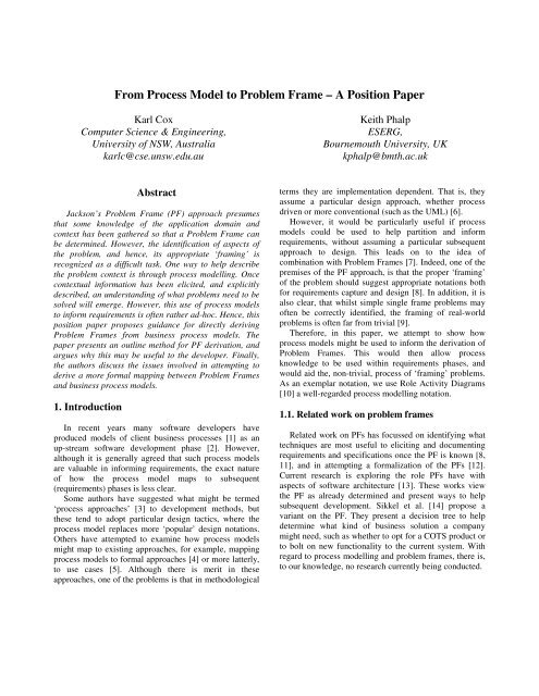
<strong>From</strong> <strong>Process</strong> <strong>Model</strong> <strong>to</strong> <strong>Problem</strong> <strong>Frame</strong> <strong>–</strong> A <strong>Position</strong> <strong>Paper</strong><br />
Karl Cox<br />
Computer Science & Engineering,<br />
University of NSW, Australia<br />
karlc@cse.unsw.edu.au<br />
Keith Phalp<br />
ESERG,<br />
Bournemouth University, UK<br />
kphalp@bmth.ac.uk<br />
Abstract<br />
Jackson’s <strong>Problem</strong> <strong>Frame</strong> (PF) approach presumes<br />
that some knowledge of the application domain and<br />
context has been gathered so that a <strong>Problem</strong> <strong>Frame</strong> can<br />
be determined. However, the identification of aspects of<br />
the problem, and hence, its appropriate ‘framing’ is<br />
recognized as a difficult task. One way <strong>to</strong> help describe<br />
the problem context is through process modelling. Once<br />
contextual information has been elicited, and explicitly<br />
described, an understanding of what problems need <strong>to</strong> be<br />
solved will emerge. However, this use of process models<br />
<strong>to</strong> inform requirements is often rather ad-hoc. Hence, this<br />
position paper proposes guidance for directly deriving<br />
<strong>Problem</strong> <strong>Frame</strong>s from business process models. The<br />
paper presents an outline method for PF derivation, and<br />
argues why this may be useful <strong>to</strong> the developer. Finally,<br />
the authors discuss the issues involved in attempting <strong>to</strong><br />
derive a more formal mapping between <strong>Problem</strong> <strong>Frame</strong>s<br />
and business process models.<br />
1. Introduction<br />
In recent years many software developers have<br />
produced models of client business processes [1] as an<br />
up-stream software development phase [2]. However,<br />
although it is generally agreed that such process models<br />
are valuable in informing requirements, the exact nature<br />
of how the process model maps <strong>to</strong> subsequent<br />
(requirements) phases is less clear.<br />
Some authors have suggested what might be termed<br />
‘process approaches’ [3] <strong>to</strong> development methods, but<br />
these tend <strong>to</strong> adopt particular design tactics, where the<br />
process model replaces more ‘popular’ design notations.<br />
Others have attempted <strong>to</strong> examine how process models<br />
might map <strong>to</strong> existing approaches, for example, mapping<br />
process models <strong>to</strong> formal approaches [4] or more latterly,<br />
<strong>to</strong> use cases [5]. Although there is merit in these<br />
approaches, one of the problems is that in methodological<br />
terms they are implementation dependent. That is, they<br />
assume a particular design approach, whether process<br />
driven or more conventional (such as the UML) [6].<br />
However, it would be particularly useful if process<br />
models could be used <strong>to</strong> help partition and inform<br />
requirements, without assuming a particular subsequent<br />
approach <strong>to</strong> design. This leads on <strong>to</strong> the idea of<br />
combination with <strong>Problem</strong> <strong>Frame</strong>s [7]. Indeed, one of the<br />
premises of the PF approach, is that the proper ‘framing’<br />
of the problem should suggest appropriate notations both<br />
for requirements capture and design [8]. In addition, it is<br />
also clear, that whilst simple single frame problems may<br />
often be correctly identified, the framing of real-world<br />
problems is often far from trivial [9].<br />
Therefore, in this paper, we attempt <strong>to</strong> show how<br />
process models might be used <strong>to</strong> inform the derivation of<br />
<strong>Problem</strong> <strong>Frame</strong>s. This would then allow process<br />
knowledge <strong>to</strong> be used within requirements phases, and<br />
would aid the, non-trivial, process of ‘framing’ problems.<br />
As an exemplar notation, we use Role Activity Diagrams<br />
[10] a well-regarded process modelling notation.<br />
1.1. Related work on problem frames<br />
Related work on PFs has focussed on identifying what<br />
techniques are most useful <strong>to</strong> eliciting and documenting<br />
requirements and specifications once the PF is known [8,<br />
11], and in attempting a formalization of the PFs [12].<br />
Current research is exploring the role PFs have with<br />
aspects of software architecture [13]. These works view<br />
the PF as already determined and present ways <strong>to</strong> help<br />
subsequent development. Sikkel et al. [14] propose a<br />
variant on the PF. They present a decision tree <strong>to</strong> help<br />
determine what kind of business solution a company<br />
might need, such as whether <strong>to</strong> opt for a COTS product or<br />
<strong>to</strong> bolt on new functionality <strong>to</strong> the current system. With<br />
regard <strong>to</strong> process modelling and problem frames, there is,<br />
<strong>to</strong> our knowledge, no research currently being conducted.
2. <strong>From</strong> process models <strong>to</strong> context diagrams:<br />
a good starting place<br />
The step from process models <strong>to</strong> context diagrams is<br />
not new [15]. Indeed, <strong>to</strong> take Jackson’s variant of the<br />
traditional context diagram and map from a Role Activity<br />
Diagram (RAD) is straightforward. Table 1 shows the<br />
components of both diagrams and how they map.<br />
Table 1. Mapping RAD <strong>to</strong> context diagram<br />
RAD<br />
Jackson Context Diagram<br />
Role Domain of Interest / Machine<br />
Interaction<br />
Interface<br />
Action -<br />
Cus<strong>to</strong>mer<br />
Apply for<br />
Account<br />
Company<br />
activate Cus<strong>to</strong>mer<br />
account<br />
Notify Cus<strong>to</strong>mer<br />
Return application<br />
Machine<br />
inform of new<br />
account<br />
Bank<br />
Machine<br />
send new<br />
Cus<strong>to</strong>mer pack<br />
Get<br />
applications<br />
Cus<strong>to</strong>mer<br />
Post<br />
applications<br />
Sign<br />
application<br />
Key<br />
Print Room<br />
Staff<br />
print<br />
starter interaction<br />
recipient interaction<br />
action<br />
Figure 1. Example role activity diagram<br />
Printers<br />
As an example, figure 1 describes a RAD of a<br />
simplified process of applying for an online share trading<br />
account. This is mapped <strong>to</strong> a context diagram (figure 2).<br />
Essentially the diagrams (figs. 1 and 2) are the same. In<br />
fact, it can be conjectured that there is a loss of<br />
information if we describe by context diagram alone.<br />
There is no explicit representation of the internal actions<br />
of the domains that are vital <strong>to</strong> the success of the<br />
business. In figure 1, actions within roles are made<br />
apparent (by black squares) <strong>–</strong> the Cus<strong>to</strong>mer role action<br />
‘sign application’. What is also required is a textual<br />
description of each domain (not detailed in this paper).<br />
D<br />
Company<br />
E<br />
Cus<strong>to</strong>mer<br />
A<br />
F<br />
Print<br />
Room<br />
Staff<br />
B<br />
Machine<br />
H<br />
C<br />
G<br />
Printer<br />
Figure 2. Context diagram<br />
Bank<br />
The interfaces between the domains can be made<br />
explicit and are described in table 2. For example, for<br />
interface A, CU!{…} means that the Cus<strong>to</strong>mer domain is<br />
responsible for the interaction with the Machine domain.<br />
Table 2. Interfaces on the context diagram<br />
Interface<br />
A<br />
B<br />
C<br />
D<br />
E<br />
F<br />
G<br />
H<br />
Description<br />
CU! {apply}<br />
MA!{notification}<br />
PRS!{retrieve application}<br />
PRS!{print application}<br />
PRS!{post application}<br />
CU!{return application}<br />
CO!{activate account}<br />
MA!{new account details}<br />
BA!{welcome}<br />
This indicates which domain is responsible for what,<br />
that is, what role they play in the process. The next step<br />
ought <strong>to</strong> be <strong>to</strong> consider how <strong>to</strong> determine the PFs. But<br />
there is a problem here.<br />
3. <strong>Problem</strong>s mapping <strong>to</strong> problem frames<br />
The context diagram, as derived from the process<br />
model, does not explicitly show the information the<br />
problem frames might need. For example, if we have a<br />
Workpiece frame, where in the context diagram or the<br />
process model is there a design domain (other than the<br />
machine) The process model does not necessarily<br />
describe what type of problems there might be <strong>–</strong> just the<br />
way that the business works for this particular scenario.<br />
As such, it is not clear whether we are describing<br />
fundamental problem frames or decomposed ‘process-
oriented’ problem frames. Hence, there is a risk of simply<br />
following the process through on<strong>to</strong> subsequent frames<br />
without consideration of the ‘big picture’. That is,<br />
bypassing the fundamental problem frames for the finer<br />
details of transforming a process model in<strong>to</strong> a set of<br />
‘process frames’.<br />
4. The frames<br />
What, then, can be derived from a process model that<br />
will determine the problem frames Figure 1 shows the<br />
Cus<strong>to</strong>mer creating an online trading account. Thus, this is<br />
a Workpiece problem frame (figure 3).<br />
Cus<strong>to</strong>mer<br />
Account<br />
Rules<br />
Machine<br />
Cus<strong>to</strong>mer<br />
Account<br />
Figure 3. Workpiece frame<br />
It can be seen that the Cus<strong>to</strong>mer Account domain in<br />
figure 3 is not apparent in either the context diagram or<br />
the RAD, though it is a fundamental (design) domain in<br />
this problem. This shows that the mapping <strong>to</strong> the context<br />
diagram from the RAD, though easy, does not necessarily<br />
provide all of the information for the problem frame. (The<br />
black dot indicates the Cus<strong>to</strong>mer Account domain is<br />
found within the machine itself <strong>–</strong> it is a design domain.)<br />
However, we can elicit this domain by further exploring<br />
the nature of the account creation activity. This can be<br />
achieved, for instance, by decomposing the RAD further,<br />
revealing the details of the interaction. We can also<br />
examine the interfaces within the context diagram.<br />
Validating the account creation process with the<br />
necessary stakeholders will verify that the Cus<strong>to</strong>mer<br />
Account domain is right <strong>–</strong> and of its legal status.<br />
4.1. Further potential problem frames<br />
There are at least two other frames identified through<br />
further analysis of the problem domain (not shown): the<br />
Commanded Behaviour frame allows the Cus<strong>to</strong>mer <strong>to</strong><br />
manipulate their Cus<strong>to</strong>mer Account online <strong>–</strong> transfer<br />
funds, buy and sell s<strong>to</strong>cks and shares. The third frame<br />
would be an Information <strong>Frame</strong>. The Cus<strong>to</strong>mer can check<br />
the current s<strong>to</strong>ck prices on the Web Application.<br />
These three core frames might need <strong>to</strong> be decomposed<br />
further. For instance, how does the Web Application<br />
show the s<strong>to</strong>ck prices Perhaps a Connection frame is<br />
required here.<br />
5. Outline of a mapping<br />
<strong>Process</strong> models do not necessarily convey the<br />
information required <strong>to</strong> determine PFs, even when<br />
mapped in<strong>to</strong> context diagrams, because domains key <strong>to</strong><br />
the success of the PF approach are not always apparent,<br />
particularly if the missing domains are design domains <strong>–</strong><br />
such as in a Workpiece. This makes the step from a<br />
process <strong>to</strong> a PF view more complicated. We thus propose<br />
initial guidelines <strong>to</strong> assist in this task. The guidelines are<br />
rudimentary and are based upon our experiences thus far.<br />
We will formalise them as our research continues. Table 3<br />
describes the steps in this (iterative) process.<br />
Table 3. RAD <strong>to</strong> problem frame<br />
Step Action<br />
1 Describe RAD<br />
2 Identify outcomes of interactions<br />
3 Identify potential domains from outcomes<br />
4 Identify potential rules that govern interactions<br />
5 Identify problem frames<br />
The first step is <strong>to</strong> describe a process model (in our<br />
case a RAD). We note that companies might have<br />
existing process models in other notations, but choose, for<br />
now, <strong>to</strong> limit our guidance <strong>to</strong> RADs.<br />
Step two identifies the outcomes of interactions<br />
between roles. In the above example, an outcome of the<br />
‘apply for account’ interaction is the creation of a new<br />
cus<strong>to</strong>mer account.<br />
As step three indicates, this outcome is then considered<br />
as a potentially new domain. Each is asked:<br />
• Is the outcome something that will be used, altered or<br />
referred <strong>to</strong> a number of times from different<br />
perspectives In other words, a domain of interest.<br />
That is, it is not simply a transient outcome. (The<br />
Cus<strong>to</strong>mer Account will be manipulated or referred <strong>to</strong><br />
through its lifetime by the Cus<strong>to</strong>mer, the Bank, and<br />
the Print Room Staff in different scenarios.)<br />
• We use Bray’s domain taxonomy <strong>to</strong> determine its<br />
type [11]. Is the domain a design domain Inert (We<br />
can say that the Cus<strong>to</strong>mer Account is something that<br />
will be created and held within the machine and will<br />
not change its state independently.) Other questions<br />
are: is the domain static (not changeable with time in<br />
any way), reactive (predictable), completely<br />
controllable (programmable), partially predictable<br />
(biddable) or entirely uncontrollable (au<strong>to</strong>nomous)
Step four explores what rules are in place <strong>to</strong> control<br />
interactions. For instance, when the Cus<strong>to</strong>mer applies for<br />
the account, they have <strong>to</strong> enter required financial<br />
information, such as current bank account details. The<br />
financial credit status of the Cus<strong>to</strong>mer, we discover, is<br />
elec<strong>to</strong>nically checked by connecting <strong>to</strong> a credit agency.<br />
Legal requirements also govern the application procedure<br />
and these have <strong>to</strong> be discovered. The machine then steps<br />
the Cus<strong>to</strong>mer through a precisely defined application<br />
procedure.<br />
Step five then identifies the PF. For example, once the<br />
RAD is described, the Cus<strong>to</strong>mer Account has been<br />
identified as an outcome of the interactions, and the legal<br />
and financial requirements (the rules) are determined. We<br />
can state: We have an inert, design domain (Cus<strong>to</strong>mer<br />
Account) <strong>–</strong> created by the Cus<strong>to</strong>mer and considered a<br />
legal document (legal / financial rules). We therefore have<br />
a Workpiece problem frame.<br />
6. Discussion<br />
This position paper has set out <strong>to</strong> outline a way <strong>to</strong><br />
derive (appropriate) <strong>Problem</strong> <strong>Frame</strong>s from process<br />
models. The method is illustrated by describing the<br />
derivation of a Workpiece frame from a Role Activity<br />
Diagram. It is shown that although traditional mapping<br />
from business processes <strong>to</strong> context diagrams might be<br />
viable, as an intermediary step <strong>to</strong>wards a problem frame,<br />
such a mapping has potential pitfalls because important<br />
design domains are often missed. Therefore, we can<br />
bypass this step and consider the problem frames direct<br />
from the process model. Key <strong>to</strong> eliciting further domains,<br />
vital <strong>to</strong> the identification of the problem frames, is<br />
exploring the interactions between roles for outcomes<br />
(potential domains) and rules (potential requirements or<br />
contraints governing use or control of the domains).<br />
6.1. Further work and potential issues<br />
Our goal is <strong>to</strong> provide a complete, formalised set of<br />
guidelines <strong>to</strong> help determine problem frames from process<br />
models. However, there are some ‘mapping’ issues <strong>to</strong> be<br />
addressed.<br />
Is it necessary for a complete mapping <strong>to</strong> be produced<br />
We are not saying that RADs and PFs are isomorphic, in<br />
the way UML sequence and collaboration diagrams are.<br />
For example, it is likely that in moving from the RAD <strong>to</strong><br />
the PF, some information is lost. When changes are made<br />
in actual requirements some of these may impact the<br />
business model, but (if they do not concern the interfaces<br />
between the domains or in the rules governing the frame)<br />
the frames may be unaltered. Hence, it may be necessary<br />
<strong>to</strong> consider a multiple mapping among business model,<br />
problem frame and requirements. Indeed, similar issues<br />
have been described among process models, use cases and<br />
class diagrams [5].<br />
This also brings in<strong>to</strong> question whether a direct<br />
mapping is most beneficial or whether it may be<br />
necessary <strong>to</strong> use an intermediate notation. Again lessons<br />
may be drawn from process modelling where notations,<br />
such as POSD, have been used in this manner [2].<br />
Finally, we note, that although well regarded, the<br />
existing PFs are seen as a starting point, and that certain<br />
contexts may yet suggest the need for further frames.<br />
7. References<br />
[1] P. Henderson, “Software <strong>Process</strong>es are Business <strong>Process</strong>es<br />
Too”, Third International Conference on the Software <strong>Process</strong>,<br />
IEEE Comp. Soc. Press, Res<strong>to</strong>n, Virginia, USA, Oct 1994.<br />
[2] K.T. Phalp, “The CAP <strong>Frame</strong>work for Business <strong>Process</strong><br />
<strong>Model</strong>ling”, Information and Software Technology, 40 (13)<br />
1998, pp. 731-744.<br />
[3] Warboys, B, Kawalek, P, Robertson, I. and M Greenwood,<br />
Business Information Systems, McGraw Hill, 1999.<br />
[4] G. Abeysinghe and K.T. Phalp, “Combining <strong>Process</strong><br />
<strong>Model</strong>ling Methods”, Information and Software Technology,<br />
vol. 39, num. 2, 1997, pp. 107-124.<br />
[5] K.T. Phalp and K. Cox, “Guiding Use Case Driven<br />
Requirements and Analysis”, 7th Int. Conf. on Object-Oriented<br />
Information Systems, Springer, LNCS, Calgary, August 27th-<br />
29th 2001, pp.329-332.<br />
[6] Jacobson, I., Booch, G., and J. Rumbaugh, The Unified<br />
Software Development <strong>Process</strong>, Addison-Wesley, 1999.<br />
[7] Jackson, M., <strong>Problem</strong> <strong>Frame</strong>s, Addison-Welsey, 2001.<br />
[8] Kovitz, B., Practical Software Requirements, Manning,<br />
1999.<br />
[9] K. Phalp, and K. Cox, “Picking the Right <strong>Problem</strong> <strong>Frame</strong> -<br />
An Empirical Study”, Empirical Software Engineering Journal,<br />
2000, 5(3), pp. 215-228.<br />
[10] Ould, M., Business <strong>Process</strong>es, Wiley, Chichester, 1995.<br />
[11] Bray, I., An Introduction <strong>to</strong> Requirements Engineering,<br />
Addison-Wesley, 2002.<br />
[12] D. Bjorner, S. Koussoube, R. Noussi, and G. Satchok,<br />
“Michael Jackson's <strong>Problem</strong> <strong>Frame</strong>s: Towards Methodological<br />
Principles of Selecting and Applying Formal Software<br />
Development Techniques and Tools”, 1st IEEE Int Conf on<br />
Formal Engineering Methods, IEEE Comp Soc Press,<br />
Hiroshima, Japan, 12-14 November, pp. 263-270.<br />
[13] J. Hall, M. Jackson, R. Laney, B. Nuseibeh, and L.<br />
Rapanotti, “Relating Software Requirements and Architectures<br />
using <strong>Problem</strong> <strong>Frame</strong>s”, RE'02, IEEE Computer Society Press,<br />
Essen, Germany, Sept 2002, pp. 137-144.<br />
[14] K. Sikkel, R. Wieringa, and R. Engmann, “A Case Base for<br />
Requirements Engineering: <strong>Problem</strong> Categories and Solution<br />
Techniques”, REFSQ'2000, S<strong>to</strong>ckholm, Sweden, 5-6 June 2000.<br />
[15] Brit<strong>to</strong>n, C. and J. Doake, Software System Development: a<br />
gentle introduction, McGraw-Hill, 1993.