CENTAFLEX®-A - CENTA Power Transmission - Sweden
CENTAFLEX®-A - CENTA Power Transmission - Sweden
CENTAFLEX®-A - CENTA Power Transmission - Sweden

You also want an ePaper? Increase the reach of your titles
YUMPU automatically turns print PDFs into web optimized ePapers that Google loves.
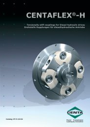
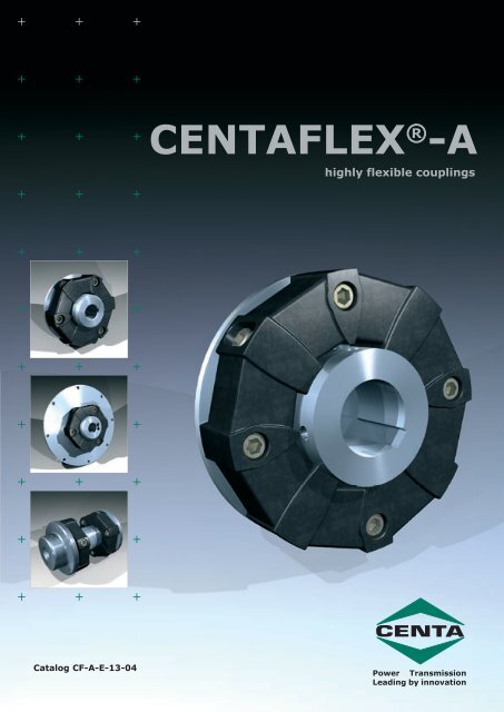
<strong>CENTA</strong>FLEX ® -A<br />
highly flexible couplings<br />
Catalog CF-A-E-13-04<br />
<strong>Power</strong> <strong>Transmission</strong><br />
Leading by innovation
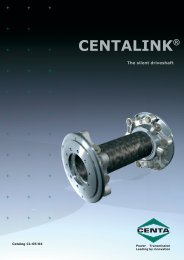
<strong>CENTA</strong>FLEX ®<br />
The success of a<br />
coupling system<br />
The <strong>CENTA</strong>FLEX -coupling was<br />
developed by <strong>CENTA</strong> Antriebe in<br />
West Germany and introduced to the<br />
market in 1970. It is patented in all<br />
industrial countries. It is also being<br />
manufactured under license in two<br />
other countries:<br />
The Miki Pulley Co. Ltd.- Japan<br />
and Lovejoy Inc. - USA<br />
In 1979 <strong>CENTA</strong> <strong>Transmission</strong>s Ltd.,<br />
an associate company of <strong>CENTA</strong><br />
Antriebe was formed in England.<br />
Meanwhile the manufacture of the<br />
<strong>CENTA</strong>FLEX-couplings increased to<br />
over 250.000 units per year.<br />
Now more than 25 agencies guarantee<br />
worldwide service and availability<br />
of <strong>CENTA</strong>FLEX-couplings.<br />
The idea<br />
A high quality coupling element<br />
which - with very little effort - enables<br />
a highly flexible coupling to be “custom<br />
built” for almost any purpose.<br />
The <strong>CENTA</strong>FLEX contains a highly<br />
elastic element which is extensively<br />
flexible in any direction, and upon<br />
which an entire coupling system is<br />
based. This coupling system embodies<br />
a combination of numerous positive<br />
characteristics, with a versatility<br />
of design from common components,<br />
not previously achieved.<br />
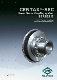
The principle<br />
A pre-stressed polygon shaped rubber<br />
element with metal parts vulcanised<br />
in. The important innovation is<br />
that the screws connecting the rubber<br />
element with the hubs are alternately<br />
arranged axially and radially. The<br />
radial screws fulfill 2 tasks:<br />
*<br />
*<br />
connecting the rubber element to<br />
the hub<br />
producing a pre-load by radial<br />
compression of the rubber column<br />
rubber element considerably raises<br />
the capacity of the coupling, since it<br />
compensates for the tensile stress<br />
which otherwise occurs in operation.<br />
Under compressive stress the capacity<br />
of rubber is multiplied.<br />
<strong>Transmission</strong> of the peripheral<br />
force from the bonded aluminium<br />
segments to the hubs is by friction.<br />
The stress in the screws is therefore<br />
purely tensile and in no way a flexional<br />
or shearing stress. For better frictional<br />
engagement, the cylindrical<br />
hubs for most sizes are knurled on<br />
the perimeter. During assembly, the<br />
knurl points press into the aluminium<br />
and result in a highly stressable combination<br />
giving a positive and friction<br />
locking connection.<br />
The materials<br />
Precision die-cast aluminium<br />
parts, vulcanised into high quality<br />
rubber; high tensile self-securing<br />
screws and steel hubs machined all<br />
over.<br />
The hubs<br />
The hubs have very simple cylindrical<br />
or flat mating faces without<br />
cams or recesses.<br />
This means that other existing elements<br />
(e.g. flywheels, brake discs,<br />
clutches, pulleys, gears etc.) can<br />
easily be used as hubs. All that is<br />
necessary in such cases is to drill and<br />
tap a few holes for fastening the rubber<br />
element. The simple, easily<br />
manufactured form of the hubs permits<br />
the manufacture of many special<br />
designs, such as elongated hubs.<br />
An entire system with the most<br />
varied designs and hubs was developed,<br />
based on the advantages described<br />
above. In addition there are<br />
hundreds of special designs. This<br />
catalog describes only the important<br />
highly flexible designs of the <strong>CENTA</strong>-<br />
FLEX system. Apart from these,<br />
several varieties with higher torsional<br />
stiffness of the elastic element have<br />
been developed, which provide - with<br />
the same connecting dimensions and<br />
hubs - for further interesting designs<br />
in other areas of applications:<br />
<strong>CENTA</strong>FLEX type H - torsionally<br />
stiff, for diesel hydraulic drives<br />
<strong>CENTA</strong>FLEX type X - torsionally<br />
very stiff, angularly flexible free of<br />
play and backlash.<br />
<strong>CENTA</strong> DRIVES<br />
of high technical<br />
standards.<br />
* <strong>CENTA</strong>FLEX<br />
is a registered trademark of <strong>CENTA</strong> Antriebe<br />
Pre-load pressure stress in the<br />
The <strong>CENTA</strong>FLEX system<br />
2
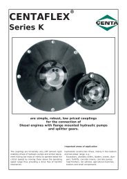
Characteristics and<br />
advantages of the<br />
<strong>CENTA</strong>FLEX-couplings<br />
=<br />
=<br />
=<br />
=<br />
=<br />
Simple, compact, smooth-face<br />
design<br />
Low weight, low moment of inertia<br />
High performance, high speed<br />
range, large bores permitted, ruptureproof<br />
Large angle of twist with progressive<br />
characteristic curve (approx.<br />
6-8° at nominal torque)<br />
High elasticity and considerable<br />
flexibility in any direction (radial,<br />
axial, angular) with low counter<br />
forces on shafts and bearings.<br />
Therefore the shafts do not have<br />
to be aligned accurately<br />
=<br />
=<br />
=<br />
=<br />
=<br />
=<br />
The action of the <strong>CENTA</strong>FLEX<br />
coupling is shock and vibration<br />
absorbing<br />
The torque is transmitted absolutely<br />
free from play, uniformly, free<br />
from noise, and electrically insulating<br />
The coupling requires no maintenance,<br />
the rubber parts suffer no<br />
wear, providing long useful life<br />
with no dirt produced by rubber<br />
particles<br />
The rubber element is air flushed<br />
all around; the heat generated is<br />
easily conducted away and the<br />
rubber element remains cool<br />
The rubber element can easily be<br />
fitted and dismantled without the<br />
use of special tools or tension<br />
bands<br />
The coupling can be very easily<br />
aligned, relying on line of sight or<br />
with the aid of a straight edge,<br />
without any special templates or<br />
gauges<br />
=<br />
=<br />
=<br />
=<br />
=<br />
The elements can be dismantled<br />
transversely without any axial displacement<br />
By slackening the radial screws,<br />
the drive can easily be seperated<br />
and rotated without dismantling<br />
No axial reaction forces are imposed<br />
on shafts and bearings due to<br />
the transmission of torque<br />
Rubber elements are available in<br />
various shorehardness grades.<br />
This permits variation of the torsional<br />
stiffness within wide limits<br />
and its adaption to the vibrational<br />
requirements of each drive<br />
system<br />
The rubber elements are available<br />
in various materials:<br />
Standard: natural rubber<br />
Special materials: Perbunan,<br />
Neoprene etc.<br />
<strong>CENTA</strong>FLEXthe<br />
coupling with the 5-way-flex<br />
Every good elastic coupling<br />
has 4-way flexibility:<br />
1. torsional elasticity<br />
2. radial flexibility<br />
3. axial flexibility<br />
4. angular flexibilty<br />
In addition, the <strong>CENTA</strong>FLEX is uniquely flexible in application, i.e. capable of modification and<br />
adaption; <strong>CENTA</strong>FLEX therefore has 5-way flexibility.<br />
3
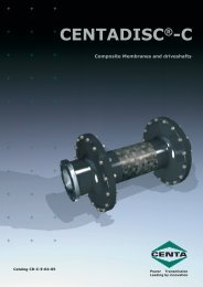
<strong>CENTA</strong>FLEX coupling<br />
design types<br />
Type 0 and 0-S<br />
The rubber element for customers’ “own designed”<br />
special applications. Available in various shorehardness<br />
grades and materials.<br />
Type 1 and 1-S<br />
Element with cylindrical hub for existing drive elements,<br />
e.g. flywheels, pulleys, brake discs, friction<br />
clutches, universal joints, freewheels, gears.<br />
Type 2 and 2-S<br />
Complete shaft couplings for all areas of mechanical<br />
engineering. After removing the axial screws, coupled<br />
machines can be removed radially, as with<br />
“three-part” couplings.<br />
Type 3 and 3-S<br />
Flanged couplings for combustion engines and<br />
many other applications. The simple adaptor plate can<br />
be adapted to fit any standard or non-standard flywheel<br />
or other component.<br />
4
Type S<br />
Design “S” is a plug-in variation for applications<br />
where axial movement or “blind” assembly in a housing<br />
is required. Design “S” is available for all design<br />
types and sizes of <strong>CENTA</strong>FLEX. In addition, there are<br />
special designs available with extended socket bolts<br />
for applications requiring large axial movement or the<br />
provision of facilities to change V-belts.<br />
Universal joint shaft, type G<br />
Highly elastic universal joint shafts for any assembly<br />
length and for a variety of applications. Connecting<br />
pieces can be varied as required, and are adaptable.<br />
With short assembly length they are suitable for<br />
speeds up to 3000 rpm.<br />
Never surpassed for simplicity and economic pricing!<br />
Universal joint shaft, type GZ<br />
Highly elastic universal joint shafts with accurate,<br />
maintenance-free centering of the central part for<br />
applications with very high speeds and/or long shaft<br />
lengths.<br />
<strong>CENTA</strong>FLEX design H<br />
Torsionally stiff, plug-in, high temperature and oilresistant<br />
design series, specially designed for diesel<br />
hydraulic drives. Numerous design types identical to<br />
those previously described, and with further special<br />
designs.<br />
Detailed description is given in catalog CF-H.<br />
<strong>CENTA</strong>FLEX design X<br />
Torsionally very stiff design series, free from play<br />
or backlash, but axially and angularly flexible. This<br />
series is temperature and oil resistant. Plug-in types<br />
suitable for blind fitting, or axially stiff types are available.<br />
This series is especially suitable for torsionally stiff<br />
universal joint shafts identical to the above design type<br />
G.<br />
Detailed description is given in catalog CF-X.<br />
5
A 1.0 Performance table<br />
<strong>CENTA</strong>FLEX size 1 2 4 8 12 16 22 25 28 30 50 80 90 140 200 250 400 remarks<br />
Pos. Description Symbol unit<br />
Nominal<br />
1 T KN Nm 10 20 50 100 140 200 275 315 420 500 700 900 1100 1700 2400 3000 5000<br />
torque<br />
Maximum<br />
2 T Kmax Nm 25 60 125 280 360 560 750 875 1200 1400 2100 2100 3150 4900 6000 8750 12500<br />
torque<br />
T KN grad 6° 6° 5° 5° 3° 5° 3° 5° 3° 5° 3° 3° 5° 3° 3° 3° 3°<br />
Angle of<br />
3 twist<br />
T Kmax grad 17° 17° 12° 14° 7,5° 14° 7,5° 14° 7,5° 14° 7,5° 7,5° 14° 7,5° 7,5° 7,5° 7,5°<br />
4 max. speed n max min -1 10000 8000 7000 6500 6500 6000 6000 5000 5000 4000 4000 4000 3600 3600 3000 3000 2500<br />
5<br />
angular<br />
elasticity<br />
DK W grad 3° 3° 3° 3° 2° 3° 2° 3° 2° 3° 2° 2° 3° 2° 2° 2° 2°<br />
6<br />
axial<br />
elasticity<br />
DK a mm 2 3 3 4 4 5 5 5 5 5 5 3 5 5 5 5 5<br />
7<br />
radial<br />
elasticity<br />
DK r mm 1,5 1,5 1,5 2 2 2 2 2 2 2 2 1,5 2 2 2 2 2<br />
8<br />
cont. oscillating<br />
torque<br />
T KW Nm 5 10 20 40 50 80 100 125 150 200 300 320 450 700 960 1250 2000<br />
9<br />
allowable<br />
energy loss<br />
P KV W 6 10 15 25 30 40 50 68 75 80 90 100 120 150 170 200 250<br />
10<br />
dyn. torsional<br />
stiffness<br />
C Tdyn Nm/rad 90 180 550 900 2700 2000 6100 2800 7500 4800 12000 16000 10500 26500 38700 43000 75000 50 Shore<br />
C Tdyn Nm/rad 140 290 850 1500 4400 3400 9000 4500 12000 7800 19000 25000 16000 40000 60000 67000 120000 60 Shore<br />
11<br />
Axialsiuffness<br />
c a N/mm 38 22 75 75 250 100 500 140 550 190 650 850 220 650 900 1150 1300<br />
12 Radialstiffness<br />
c r N/mm 150 150 500 500 1000 500 1300 600 1400 750 2200 2900 1000 2300 3100 4100 6000<br />
13 angular c w Nm/grad 0,3 0,3 2,4 3,6 9,0 5,0 12,0 7,0 17,0 9,0 26,0 34,0 17,0 38,0 48,0 68,0 88,0<br />
stiffness<br />
Figures given for Pos. 3, 11, 12, 13 are values for a shorehardness of 60° measured statically (C dyn = C stat •1,3)<br />
dependant<br />
upon speed<br />
dependant<br />
upon speed<br />
Nominal torque T KN : Maximum torque T Kmax : Continuously oscillating torque T KW :<br />
Torque which can be transmitted throughout the Torque which may be applied for short periods Amplitude of continuously permissible torque fluctuation<br />
entire permitted speed range. 10 5 times, pulsating in the same direction of rotation, at max. frequency of 10Hz and a basic load up to<br />
or 5x10 4 alternating<br />
nominal torque T KN<br />
A 1.1<br />
Starting up factor<br />
Z = start frequency per hour<br />
A 1.2 Frequency factor<br />
f in Hz £ 10 > 10<br />
S f 1<br />
f<br />
10<br />
A 1.3 Shorehardness<br />
Conversion factor u<br />
Shore 50 60 70 75<br />
u 0,7 1 1,6 2,3<br />
A 1.4<br />
Z £120 120< Z £ 240 >240<br />
S z 1,0 1,3 ask<br />
<strong>CENTA</strong><br />
Surge or Pulse factor<br />
SA/SL<br />
1,6 Light starting load<br />
1,9 Medium starting load<br />
2,2 Heavy starting load<br />
A 1.5 Resonance factor V R<br />
relative damping ψ<br />
Natural rubber(NR)<br />
Shore VR ψ<br />
50 10 0,6<br />
60 8 0,78<br />
A 1.6 Temperature factor<br />
A 1.7 Permissible angular and radial misalignment<br />
permissible angular and parallel offset misalignment<br />
is dependant upon the speed when utilising<br />
the nominal torque capacity. % of line 5 or 7<br />
6
£<br />
‡<br />
Coupling selection<br />
The <strong>CENTA</strong>FLEX-coupling must be suitable dimensioned<br />
to prevent the stresses:<br />
a) Nominal torque T KN<br />
b) Maximum torque T Kmax<br />
c) Continuously oscillating torque T KW<br />
from exeeding the permissible values in any operational<br />
state. The following formulae will be helpful.<br />
Stress due to the torque<br />
The permissible nominal torque at all operating temperatures<br />
must be at least as great as the nominal torque of the<br />
drive or load side.<br />
Total mass moment of inertia<br />
drive side J A kgm²<br />
load side J L kgm²<br />
Dyn. torsional stiff- C Tdyn Nm/rad<br />
ness of the coupling<br />
Determining the resonance speed of the i th order<br />
30 JA<br />
+ JL<br />
-1<br />
nR<br />
= CTdyn<br />
min<br />
Π i JA<br />
JL<br />
J A J L<br />
We shall be pleased to carry out torsional vibration calculations<br />
i = number of oscillations generated per revolution<br />
T AN S t £ T KN ‡ T LN S t<br />
Distance from resonance<br />
Where there is considerable oscillation generated, the resonance<br />
can be placed outside the operating speed range by<br />
Factors of influence:<br />
the appropriate selection of the coupling torsional stiffness.<br />
Nominal torque drive side T AN Nm<br />
The following applies for the required resonance distance:<br />
load side T LN Nm<br />
Temperature factor S t (diagram A 1.6)<br />
nB<br />
= 1,5 - 2<br />
nR<br />
Performance formula:<br />
T AN T KN T LN = 9555 P kW<br />
Passing through resonance<br />
⋅ Nm<br />
n rpm<br />
The permissible max. torque TKmax must not be exceeded<br />
while running through the resonance.<br />
Factors of influence:<br />
Stress due to torque pulses:<br />
generating torque<br />
The permissible max. torque of the coupling must at all operating<br />
temperatures be at least as great as the torque pulses<br />
drive side T Ai Nm<br />
load side T<br />
T AS and T LS (Nm) occuring in operation.<br />
Li Nm<br />
Resonance factor V R (Table A 1.5)<br />
Factors of influence :<br />
start-up factor S z (Table A 1.1)<br />
Drive side oscillation generation<br />
pulse factor<br />
drive side S A (Table A 1.4)<br />
T Kmax ‡ M A T Ai V R S Z S t Nm<br />
load side S L<br />
Load side oscillation generation<br />
Mass factor<br />
T Kmax ‡ M L T Li V R S Z S t Nm<br />
drive seite M A<br />
JL<br />
Continuously oscillating torque<br />
MA<br />
=<br />
For the operating frequency, the oscillating torque must be<br />
load side M L<br />
JA<br />
+ JL<br />
compared with the permissible continuously oscillating torque<br />
of the coupling. The continuously oscillating torque<br />
JA<br />
ML<br />
=<br />
existing is dependant upon the amplifying factor outside the<br />
Drive side pulse<br />
JA<br />
+ JL<br />
resonance.<br />
T Kmax ‡ M A T AS S A S Z S t Nm<br />
Amplifying factor V outside the resonance.<br />
1<br />
approximation formula<br />
V ~<br />
2<br />
Load side pulse<br />
1(n/n R)<br />
T Kmax ‡ M L T LS S L S Z S t Nm<br />
Drive side oscillation generation<br />
Stress due to a periodic oscillating torque<br />
T KW ‡ M A T Ai V S t S f Nm<br />
Position of resonance (resonance speed)<br />
Load side oscillation generation<br />
For easier calculation, the existing unit is best reduced to a<br />
2-mass torsional oscillating system if possible.<br />
T KW ‡ M L T Li V S t S f Nm<br />
Frequency factor S f (Table A 1.2)<br />
for you in our<br />
offices.<br />
C Tdyn<br />
All data, dimensions and information of this catalog are given without guarantee.<br />
Amendments and improvements may be made without notice.<br />
This technical document has legal protection (copyright).<br />
7
Dimensions,<br />
Basic Design<br />
Types<br />
0, 1, 2,<br />
0-S, 1-S, 2-S.<br />
Size d 1 d 2<br />
min. max. min.. max. d 3 A B B 1 C 1 E G L 1 L 2 L 3 M N 1 N 2 S T S<br />
1 8 19 25 56 24 7 7 26 22 11 24 24 50 M 6 30 36 2 10<br />
2 10 26 38 85 24 8 8 32 20 10 287 28 60 M 8 40 55 4 14<br />
4 12 30 45 100 28 8 8 34 24 12 30 30 64 M 8 45 65 4 14<br />
8 38 55 120 32 10 10 46 28 14 42 42 88 M 10 60 80 4 17<br />
12 38 55 122 32 10 10 46 28 14 42 42 88 M 10 60 80 4 17<br />
16 48 70 150 42 12 12 56 36 18 50 50 106 M 12 70 100 6 19<br />
22 48 70 150 42 12 12 56 36 18 50 50 106 M 12 70 100 6 19<br />
25 55 85 170 46 14 14 61 40 20 55 55 116 M 14 85 115 6 22<br />
28 55 85 170 46 14 14 61 40 20 55 55 116 M 14 85 115 6 22<br />
30 65 100 200 58 16 16 74 50 25 66 66 140 M 16 100 140 8 25<br />
50 65 100 200 58 16 16 74 50 25 66 66 140 M 16 100 140 8 25<br />
80 65 100 205 65 16 16 75 61 35 66 66 145 M 16 100 140 4 25<br />
90 85 110 260 70 19 20 88 62 31 80 80 168 M 20 125 160 8 32<br />
140 85 110 260 70 19 20 88 62 31 80 80 168 M 20 125 160 8 32<br />
200 105 110 300 80 19 20 102 72 36 94 90 192 M 20 145 160 8 32<br />
250 115 130 340 85 19 20 108 77<br />
22,5<br />
54,5<br />
100 100 208 M 20 160 195 8 32<br />
400 120 140 370 105 25 28 135 95 28,5<br />
66,5<br />
125 125 260 M 24 170 200 10 45<br />
The <strong>CENTA</strong>FLEX couplings<br />
have been proven in many areas<br />
of mechanical engineering. The<br />
major area of application lies with<br />
diesel driven stationary and mobile<br />
equipment as well as a very wide<br />
range of industrial applications.<br />
The photographs below illustrate<br />
some typical examples of application:<br />
Boat drives, mechanical conveying<br />
and handling, agricultural<br />
machinery, front power take-off on<br />
diesel engines for the most varied<br />
applications.<br />
Typical examples of application for <strong>CENTA</strong>FLEX -couplings<br />
8
Weight kg Mass moment of inertia J kgcm²<br />
T R P O T K /Division Type. 0 Type. 1 Type. 2 Type. 1/S Type. 2/S Type. 0 Type. 1 Type. 2 Type. 1/S Type. 2/S Size<br />
10,5 6,5 18 5 44 / 2x180° 0,06 0,21 0,47 0,24 0,49 0,35 0,75 1,6 0,86 1,7 1<br />
13,5 8,5 12 14,2 68 / 2x180° 0,15 0,46 1,06 0,49 1,09 1,25 2,5 7,3 3,3 8,1 2<br />
13,5 8,5 17 18,5 80 / 3x120° 0,21 1,31 2,31 0,70 1,70 3,3 5,0 11,3 6,5 12,8 4<br />
16,5 10,5 20,5 20,5 100 / 3x120° 0,32 1,35 3,45 1,44 3,54 7,0 15,0 41,0 18,6 44,6 8<br />
16,5 10,5 20,5 20,5 100 / 4x 90° 0,35 1,45 3,55 1,56 3,66 8,4 18,2 44,2 20,0 46,1 12<br />
18,5 12,5 23,5 25,2 125 / 3x120° 0,65 2,28 6,16 2,33 6,21 23,4 42,5 118,8 49,1 125,4 16<br />
18,5 12,5 23,5 25,2 125 / 4x 90° 0,70 2,52 6,42 2,62 6,62 26,6 50,4 126,5 70,2 146,3 22<br />
21,5 14,5 26,0 27,0 140 / 3x120° 0,84 3,59 9,31 3,77 9,49 50,2 90,7 215,0 102,7 227,0 25<br />
21,5 14,5 26,0 27,0 140 / 4x 90° 0,95 3,79 9,51 4,05 9,76 55,6 102,4 247,8 113,2 258,5 28<br />
24,5 16,5 34,5 34,5 165 / 3x120° 1,43 5,66 15,21 6,02 15,57 102,0 200,0 545,5 220,4 565,9 30<br />
24,5 16,5 34,5 34,5 165 / 4x 90° 1,60 6,04 15,60 6,50 16,05 104,0 205,0 550,5 253,4 598,9 50<br />
24,5 16,5 34,5 34,5 165 / 4x 90° 2,10 6,85 16,60 7,25 17,00 131,8 240,3 585,5 263,9 609,1 80<br />
30,5 20,5 45,5 47,0 215 / 3x120° 3,30 11,55 28,67 12,23 29,35 450,0 657,5 1630,1 759,2 1731,8 90<br />
30,5 20,5 45,5 47,0 215 / 4x 90° 3,65 12,33 29,45 13,22 30,36 572,0 770,0 1742,6 873,0 1845,6 140<br />
30,5 20,5 44,5 45,5 250 / 4x 90° 5,75 13,13 33,16 14,07 34,11 1356,0 1598,0 3050,0 1686,0 3129,0 200<br />
30,5 20,5 60,0 59,0 280 / 4x 90° 7,10 18,98 44,42 20,01 45,44 1754,0 2404,0 5264,0 2529,0 5389,0 250<br />
42,5 24,5 72,0 77,0 300 / 4x 90° 11,25 26,58 57,23 29,34 59,95 3380,0 4485,0 9130,0 4683,0 9328,0 400<br />
Elastic couplings mounted on friction clutches. The<br />
last photograph shows a particu-larly interesting application:<br />
A <strong>CENTA</strong>FLEX between an electric motor and<br />
reduction gear, and a second <strong>CENTA</strong>FLEX coupling<br />
as a torsional oscillation damping and shock absorbing<br />
type of coupling in front of a chain drive.<br />
9
<strong>CENTA</strong>FLEX-<br />
Universal Joint Shafts<br />
G<br />
GZ<br />
T KN A B C D d H L 2 N 2 R T T K M Z H8<br />
Size Nm min. max.<br />
1 10 24 7 5 56 8 25 13 24 36 30 1,5 44 2x M 6 52<br />
2 20 24 8 5 85 12 38 14 28 55 40 1,5 68 2x M 8 80<br />
4 50 28 8 5 100 15 45 16 30 65 45 1,5 80 3x M 8 95<br />
8 100 32 10 5 120 18 55 18 42 80 60 1,5 100 3x M10 115<br />
12 140 32 10 5 122 18 55 18 42 80 60 1,5 100 4x M10 115<br />
16 200 42 12 5 150 20 70 24 50 100 70 1,5 125 3x M12 145<br />
22 275 42 12 5 150 20 70 24 50 100 70 1,5 125 4x M12 145<br />
25 315 46 14 5 170 20 85 26 55 115 85 1,5 140 3x M14 165<br />
28 420 46 14 5 170 20 85 26 55 115 85 1,5 140 4x M14 165<br />
30 500 58 16 5 200 25 100 33 66 140 100 1,5 165 3x M16 195<br />
50 700 58 16 5 200 25 100 33 66 140 100 1,5 165 4x M16 195<br />
80 900 65 16 5 205 25 100 34,5 66 140 100 1,5 165 4x M16 195<br />
90 1100 70 19 5 260 30 110 39 80 160 125 1,5 215 3x M20 250<br />
140 1700 70 19 5 260 30 110 39 80 160 125 1,5 215 4x M20 250<br />
200 2400 80 19 10 300 35 110 44 90 160 145 1,5 250 4x M20 290<br />
250 3000 85 19 10 340 40 130 46 100 195 160 1,5 280 4x M20 330<br />
400 5000 105 25 10 370 40 140 57 125 200 170 1,5 300 4x M24 360<br />
Dimension “L” should be specified on enquiries and orders.<br />
The <strong>CENTA</strong>FLEX universal<br />
joint shafts are proven, extremely<br />
simple, versatile and torsionally<br />
highly elastic.<br />
They dampen noise, torsional<br />
oscillation and shock.<br />
They compensate for considerable<br />
axial, radial and angular misalignment.<br />
The lengths are not standardised,<br />
but made individually in accordance<br />
with customers’ requirements;<br />
but they are, nonetheless very<br />
moderately priced. The connecting<br />
parts (hubs) can also be adapted<br />
to suit requirements. <strong>CENTA</strong>FLEX<br />
universal joint shafts require no<br />
maintenance whatsoever; the centre<br />
part can be removed radially<br />
(transversely) without displacing<br />
the coupled machines.<br />
Design G<br />
This is the simplest design type;<br />
the centre part is centered only by<br />
the <strong>CENTA</strong>FLEX elements. Suitable<br />
for short and medium lengths<br />
and for speeds up to approx. 1500<br />
rpm.<br />
Please also see the diagram on<br />
page 11 for additional information.<br />
Design GZ<br />
Here, the centre assembly is<br />
accurately located on the centering<br />
plate and maintenance free bearings.<br />
This design is suitable for<br />
long lengths and/or high speeds.<br />
The centre assembly can be withdrawn<br />
without disturbing the driving<br />
or driven hubs. In cases of<br />
doubt, the decision whether to<br />
chose design G or GZ should be<br />
left to us, since a clear demarcation<br />
is difficult.<br />
The sectional drawing on the left<br />
shows one of the many special designs,<br />
with an adaptor plate for a<br />
diesel engine and with extensive<br />
axial movement permitted by<br />
means of long socket bolts.<br />
10
Selection of <strong>CENTA</strong>FLEX<br />
Universal Joint Shafts:<br />
Torque capacity is in accordance<br />
with the table on page 6.<br />
Due to the use of two <strong>CENTA</strong>-<br />
FLEX elements, the values of axial<br />
elasticity and for the angle of twist<br />
are doubled, the values for torsional<br />
stiffness and the axial spring<br />
values are halved.<br />
Permissible angular misalignment<br />
is shown in diagram A 1.7<br />
and the following formula:<br />
Design G:<br />
a = tan α (L- 2H)<br />
a = parallel offset (mm)<br />
Design GZ:<br />
a = tan α [L-2 (H+C)]<br />
L; H and C as in dimension<br />
table.<br />
The maximum permissible length<br />
for the centre part is dependant on<br />
the speed and can be found in the<br />
diagram on the right.<br />
The dotted line gives an approximate<br />
indication as to whether type G<br />
or GZ should be used on short<br />
shafts, but only in respect of speed,<br />
not of length. We recommend that all<br />
shafts regardless of length are of the<br />
GZ type if they run at speeds above<br />
those indicated by the dotted line.<br />
Examples of typical applications:<br />
Screw Jacks, compressors, engine<br />
test benches<br />
(Size 16 GZ; n= 7200 rpm).<br />
Other applications: Boat drives, diesel<br />
drives for centrifugal pumps, air<br />
conditioning, construction machinery,<br />
general mechanical engineering.<br />
11
<strong>CENTA</strong>FLEX-couplings for diesel engines<br />
This is the central point of application<br />
for <strong>CENTA</strong>FLEX. We supply<br />
suitable <strong>CENTA</strong>FLEX couplings<br />
for practically any diesel or petrol<br />
engine, to suit the flywheel side as<br />
well as for the power take-off at the<br />
front end of the crankshaft, e.g.<br />
Caterpillar, Detroit, Deutz,<br />
Dorman, Ford, Gardner, Hatz,<br />
Leyland, Lister, MAN, Perkins,<br />
Petter, Rolls Royce, VW and many<br />
others.<br />
The number of the existing<br />
assembly drawings is so great that<br />
it is not possible to include them in<br />
a brochure.<br />
The type most extensively used<br />
for diesel engine flywheels is SAE<br />
standard J620. The dimensional<br />
sheet shows appropriate couplings<br />
for the plug-in (blind fitting) design<br />
(e.g. for generator drives).<br />
For Deutz and Perkins engines,<br />
flywheels with tapped holes are<br />
available for <strong>CENTA</strong>FLEX couplings.<br />
This enables couplings to<br />
be fitted direct - without and adaptor<br />
plate- with types 1 and 1-S, and<br />
results in particularly compact and<br />
economically priced couplings.<br />
Please ask for our detailed offer<br />
for your specific requirements.<br />
1 Deutz F3-6L912<br />
available for<br />
engines 208, 210, 511, 912, 913 and 413<br />
2 Perkins 3, 4, 6 and 8 cylinders<br />
Perkins part-no. 31221322<br />
3 Intermediate couplings for universal joint<br />
shafts.<br />
Type<br />
3-S-SAE<br />
d 1<br />
appropriate<br />
Size min. max. d 3 A 3 C 3 L 1 N 1 S T K /division SAE-flange<br />
8 12 38 120 38 52 42 60 4 100/3x120° 6½” 7½”<br />
16 15 48 150 48 62 50 70 6 125/3x120° 6½” 7½” 8”<br />
22 15 55 170 52 67 55 85 6 140/3x120° 8”<br />
25 15 55 170 56 71 55 85 6 140/3x120° 10”<br />
30 20 65 200 68 84 66 100 8 165/3x120° 10” 11½”<br />
50 20 65 200 68 84 66 100 8 165/4x 90° 10” 11½”<br />
90 30 85 260 80 98 80 125 8 215/3x120° (10”) 11½” 14”<br />
140 30 85 260 80 98 80 125 8 215/4x 90° (10”) 11½” 14”<br />
200 35 105 300 90 112 94 145 8 250/4x 90° 11½” 14” 16”<br />
250 40 115 340 95 118 100 160 8 280/4x 90° 11½” 14” 16”<br />
400 40 120 370 115 150 125 170 10 300/4x 90° 14” 16”<br />
nominal D A D T D j d 2 Z weight Mass moment<br />
SAE f7 kg of inertia<br />
size<br />
J kgcm²<br />
6½” 215,9 200,02 180 9 6 2,60 147<br />
7½” 241,3 222,25 200 9 8 3,25 228<br />
8” 263,52 244,47 220 11 6 3,90 328<br />
10” 314,32 295,27 270 11 8 7,20 966<br />
11½” 352,42 333,37 310 11 8 9,60 1584<br />
14” 466,72 438,15 405 13 8 19,40 5421<br />
16” 517,5 489 450 13 8 24,60 8272<br />
Example of coupling reference CF-A-30-3-S-SAE10<br />
* Z = number of holes<br />
1 2 3<br />
12
<strong>CENTA</strong>LOC<br />
Clamping Hub<br />
It is well known that all splined<br />
steel connections, which are not<br />
free from play tend to wear due to<br />
“hammering” and fretting corrosion.<br />
The shaft of hydrostatic pumps<br />
for mobile equipment nearly<br />
always have spline or involute profiles.<br />
The unavoidable play, due to<br />
the manufacturing tolerances on<br />
the flanks of these profiles between<br />
shaft and hub, permits minor<br />
relative movements in operation<br />
leading to wear. Even hubs and<br />
shafts made from high quality and<br />
hardened steels cannot solve this<br />
problem in its essence, but can at<br />
best only reduce the wear. The<br />
problem can be solved effectively<br />
only when the connection between<br />
shaft and hubs is made free from<br />
play.<br />
With this objective in mind, we<br />
developed the <strong>CENTA</strong>LOC clamping<br />
hub. This new type of clamp<br />
hub has a slot arranged tangentially<br />
to the bore. On the inner part of<br />
this slot, strong forces are applied<br />
through one or more set screws.<br />
The hub is radially pressed<br />
inwards in this area, i.e. pressed<br />
firmly against the shaft profile. The<br />
opposing reaction forces of the<br />
clamping screw are diverted within<br />
the hub causing it to be pressed<br />
firmly against the shaft. The hub<br />
thus becomes firmly locked<br />
against the shaft around its diameter<br />
i.e. absolutely free from play.<br />
It is at the same time also locked<br />
axially. The incidental minor deformations<br />
of the hub occur within the<br />
elastic limit and there is no permanent<br />
deformation. After slackening<br />
the clamping screws, the hub can<br />
easily be dismantled or re-fitted.<br />
This procedure can be repeated as<br />
often as may be required.<br />
Path of clamping force<br />
Use of the <strong>CENTA</strong>LOC clamping<br />
hub does not present any difficulty<br />
at the assembly stage with<br />
the blind fitting design type S, H or<br />
X. When assembling for example a<br />
motor and pump, the cylindrical<br />
coupling hub is simply mounted on<br />
the pump shaft and locked prior to<br />
motor and pump being assembled<br />
together. The coupling housing<br />
does not, therefore, require any<br />
access holes.<br />
The <strong>CENTA</strong>LOC clamp hub<br />
can be selected for all design types<br />
of <strong>CENTA</strong>FLEX. The clamping<br />
should preferably be arranged in<br />
the cylindrical inner hub; but it is<br />
also possible to manufacture flanged<br />
hubs with the clamping facility.<br />
The connecting details and<br />
external dimensions of the CEN-<br />
TAFLEX coupling are not altered<br />
by the <strong>CENTA</strong>LOC clamping facility.<br />
The patented <strong>CENTA</strong>LOC<br />
clamp hub has already been proved<br />
in thousands of hard applications.<br />
It is recommended by major<br />
manufacturers of hydraulic pumps.<br />
This is evidence of the fact that you<br />
can expect real solutions to your<br />
problems for <strong>CENTA</strong> power transmission<br />
engineers.<br />
(R) <strong>CENTA</strong>LOC is a registered trademark of <strong>CENTA</strong> Antriebe<br />
13
Fitting instructions for <strong>CENTA</strong>FLEX-couplings<br />
with highly elastic rubber elements<br />
Important notes -<br />
observe strictly<br />
The radial and axial screws connecting<br />
the rubber element to the hubs must all be<br />
tightened to the torque given in the table<br />
below, using a torque wrench.<br />
Tightening with a torque wrench is particularly<br />
important withthe larger sizes.<br />
Tightening “by feel” will not do, as experience<br />
has proved the tightening torques in<br />
such cases are far too low.<br />
Tightening torques which are too low<br />
will inevitably lead to slackening of the<br />
screws in service and consequently to the<br />
destruction of the coupling.<br />
Ensure that on tightening the screws,<br />
the aluminium bushes in the rubber part are<br />
not twisted at the same time, but sit straight.<br />
In order to reduce friction between the<br />
screw head and the aluminium part, a small<br />
amount of grease should be applied under<br />
the head of the screw before fitting. If<br />
necessary, use a suitable tool for applying<br />
counter pressure on the element to prevent<br />
twisting of the rubber part during tightening<br />
of the screws. This is particularly<br />
important with the radial screws, otherwise<br />
the cylindrical faces between aluminium<br />
insert and hub will not engage on the full<br />
area, but only on two corners. This will<br />
inevitably lead to slackening of the screws<br />
and subsequent destruction of the coupling.<br />
If the coupling is supplied in a pre-assembled<br />
state, do not dismantle it, but fit it in<br />
this condition.<br />
wrong<br />
correct<br />
<strong>CENTA</strong>FLEX Size 1 2 4 8 / 12 16 / 22 25 / 28 30 50 / 80 90 / 140 200 / 250 400<br />
Screw Size M 6 M 8 M 8 M 10 M 12 M 14 M 16 M 16 M 20 M 20 M 20 / M24<br />
Tightening torque Nm 10 25 25 50 85 140 220 220 500 500 610 /1050<br />
mKp 1,0 2,5 2,5 5 8,5 14 22 22 50 50 61 / 105<br />
Sequency of Assembly<br />
grease<br />
radial<br />
axial<br />
radial<br />
grease<br />
axial<br />
Standard Design<br />
Fith the hubs onto the shafts or the<br />
adaptor plate onto the flywheel.<br />
Fit the rubber element to the flanged<br />
hub or flywheel, by means of axial screws.<br />
This must be carried out before engaging<br />
the radial screws in the cylindrical<br />
hub.<br />
Push the shaft-mounted cylindrical hub<br />
inside the rubber element and then fasten<br />
the rubber element on it with radial screws.<br />
During this process, the rubber element is<br />
compressed radially and is pre-loaded for<br />
increased capacity.<br />
Design S (plug-in or blind<br />
fitting type)<br />
Fit the hubs onto the shafts or the adaptor<br />
plate onto the flywheel.<br />
Fit the axial socket bolts on ot the flange<br />
hub or adaptor plate on the flywheel.<br />
Position the element with the side having<br />
the rubber free face of the axial aluminium<br />
inserts towards the flange hub and,<br />
using the radial screws, mount it on the cylindrical<br />
hub. During this process, the rubber<br />
element is pulled together radially and<br />
receives its pre-load. Then, push the coupled<br />
elements together and in doing so,<br />
carefully slide the coupling with light axial<br />
pressure onto the socket bolts. The rubber<br />
element is subjected to a little more radial<br />
compression by the socked bolts, and the<br />
pre-load is thus increased. The axial bores<br />
in the rubber element should be smeared<br />
lightly with grease beforehand to allow the<br />
socket bolts to slide easily in the inserts.<br />
14
Use only the “Inbus Plus” screws provided<br />
which are marked on the threads with<br />
a micro-encapsulated adhesive which locks<br />
the screw in the thread and secures them<br />
reliably against slackening. For adequate<br />
effect, the hardening period for this adhesive<br />
after bolting up is approximately 4-5<br />
hours at room temperature (20°C). The<br />
coupling should not be operated before this<br />
period has elapsed.<br />
The adhesive will be fully hardened<br />
after 24 hours. Higher temperatures will<br />
speed up the hardening process, at 70°C<br />
(using a hot air blower), for instance, the<br />
hardening will take only 15 minutes. Inbus<br />
Plus is temperature proof between -80° and<br />
+90°C and the screws can be reused up to<br />
3 times max. Any adhesive stripped off<br />
during bolting up will settle between the hub<br />
and the aluminium part, but this will have a<br />
beneficial effect in that it enhances the friction<br />
grip between these parts.<br />
Note: Anaerobic adhesives (such as<br />
Loctite, Omnifitic etc.) will loosen the adhesion<br />
of the rubber and the insert and will<br />
consequently destroy the coupling.<br />
Such adhesives should therefore be<br />
avoided if possible. Where the use of this<br />
adhesive is unavoidable apply it very sparingly<br />
so that no surplus adhesive will<br />
moisten the rubber.<br />
We cannot accept any complaints concerning<br />
rubber parts which have become<br />
defective through the action of adhesives<br />
not supplied or recommended by us.<br />
The coupling is completely maintenance-free<br />
and does not require any lubrication.<br />
Splashing with oil and similar substances<br />
should be avoided, since natural rubber<br />
is not oil-resistant.<br />
However occasional minor contact with<br />
oil or grease is not harmful as this oil will be<br />
thrown off during rotation of the coupling.<br />
<strong>CENTA</strong>LOC clamping hub<br />
If the hubs are equipped with <strong>CENTA</strong>-<br />
LOC clamping (see page 13), the clamping<br />
screws must be tightened at least to the following<br />
tightening torques:<br />
clamp screw Tightening torque (Nm)<br />
M 10 30<br />
M 12 50<br />
M 14 70<br />
M 16 120<br />
M 20 200<br />
After assembly, the coupling should be<br />
carefully aligned if the coupled elements<br />
are not already in good alignment by virtue<br />
of being spigot located. In the interest of a<br />
long service life of the coupling, the higher<br />
the speed, the more meticulous should the<br />
alignment be. In design type 2, the alignment<br />
can very easily be checked with a<br />
straight edge. The outer diameter of the<br />
flange hub must be flush with the outer diameter<br />
of the rubber element in those areas<br />
where the radial screws sit: i.e. in different<br />
radial positions.<br />
In design types 1 and 3 the distance “Z”<br />
must be measured at all axially bolted<br />
points of the rubber element (2, 3 or 4<br />
points depending on the size) and must be<br />
set as accurately as possible to the value<br />
“Z” quoted in the table below.<br />
For spigot located components there is<br />
no need to align the coupling.<br />
Position of cylindrical hubs:<br />
The long end of the cylindrical hub, usually<br />
identifiably by a chamfer, is normally as<br />
shown in the drawing below. However, in<br />
some special applications, the hub must be<br />
reversed. When in doubt, install as shown<br />
in the relevant installation drawing.<br />
Installation table: Screw fastener<br />
details, dimension “S” between the hubs<br />
and dimension “Z”.<br />
<strong>CENTA</strong>FLEX Size 1 2 4 8 / 12 16 / 22 25 / 28 30 50 /80 90 140 200 250 400<br />
Standard Design M6x10 M8x20 M8x25 M10x30 M12x35 M14x40 M16x50 M16x50 M20x65 M20x65 M20x80 M20x80 M24x100<br />
M6x25<br />
M20x100<br />
Type “S”<br />
Special bolt M6 M8 M8 M10 M12 M14 M16 M16 M20 M20 M20 M20 M24<br />
screws M6x10 M8x10 M8x25 M10x30 M12x35 M14x40 M16x50 M16x50 M20x65 M20x65 M20x65 M20x80 M20x100<br />
Universal joint shaft M6x10 M24x100<br />
G M6x25 M8x20 M8x25 M10x30 M12x35 M14x40 M16x50 M16x50 M20x65 M20x65 M20x65 M20x80 M20x100<br />
u/j shaft radial M6x10 M8x20 M8x25 M10x30 M12x35 M14x40 M16x50 M16x50 M20x65 M20x65 M20x65 M20x80 M20x100<br />
GZ axial M6x30 M8x25 M8x30 M10x35 M12x40 M14x45 M16x55 M16x55 M20x70 M20x70 M20x80 M20x90 M24x100<br />
Dimension “S”<br />
mm 2 4 4 4 6 6 8 8/4 8 8 8 8 10<br />
Dimension “Z”<br />
mm 13 22,5 37,5 30/31 40 42,5 50 50/52,5 67,5 67,5 77,5 90 100<br />
15
<strong>CENTA</strong> Australia<br />
<strong>CENTA</strong> Netherland<br />
<strong>CENTA</strong> Denmark<br />
<strong>CENTA</strong> Headquarters Germany<br />
<strong>CENTA</strong> Norway<br />
<strong>CENTA</strong> Italy <strong>CENTA</strong> Great Britain <strong>CENTA</strong> Singapore<br />
<strong>CENTA</strong><br />
Subsidiaries<br />
Australia<br />
<strong>CENTA</strong> <strong>Transmission</strong>s Pty. Ltd.<br />
P.O. Box 6245<br />
South Windsor, NSW 2756<br />
Austria<br />
Hainzl Industriesysteme GmbH<br />
Industriezeile 56<br />
A-4040 Linz<br />
Belgium<br />
Caldic Techniek Belgium N.V.<br />
Tollaan 73<br />
B-1932 Sint-Stevens-Woluwe<br />
Brazil<br />
<strong>CENTA</strong> Transmissoes Ltda.<br />
Rua Josè Américo<br />
Cançado Bahia 199<br />
Cidade Industrial<br />
32.210-130 Contagem MG<br />
Canada<br />
<strong>CENTA</strong> CORP.<br />
815 Blackhawk Drive<br />
Westmont, IL 60559, USA<br />
Chile<br />
Comercial TGC Ltda.<br />
Calle Dr. M. Barros Borgoño 255-263<br />
Casilla 16.800 (P.O. Box)<br />
Santiago-Providencia<br />
China<br />
<strong>CENTA</strong> Representative Office<br />
Room.11C, Cross Region Plaza<br />
No. 899 LingLing Road<br />
Shanghai, PC200030<br />
Denmark<br />
<strong>CENTA</strong> <strong>Transmission</strong>er A/S<br />
A.C. Illums Vej 5<br />
DK-8600 Silkeborg<br />
Egypt<br />
Hydraulic Misr<br />
P.O. Box 418<br />
Tenth of Ramadan City<br />
Finland<br />
Movetec Oy<br />
Hannuksentie 1<br />
FIN-02270 EPOO<br />
France<br />
Prud’Homme<br />
<strong>Transmission</strong>s<br />
66 Rue des St. Denis<br />
B.P. 73<br />
F-93302 Aubervilliers Cedex<br />
Germany<br />
<strong>CENTA</strong> Antriebe<br />
Kirschey GmbH<br />
Bergische Str. 7<br />
D-42781 Haan<br />
Great Britain<br />
<strong>CENTA</strong> <strong>Transmission</strong>s Ltd.<br />
Thackley Court,<br />
Thackley Old Road,<br />
Shipley, Bradford,<br />
West Yorkshire, BD18 1BW<br />
Greece<br />
Industry: Marine:<br />
Kitko S.A. Technava S.A.<br />
1, Rodon St. 6,Loudovikou Sq.<br />
17121 N.Smymi 18531 Piraeus<br />
Athens<br />
Hong Kong/China<br />
Foilborn Enterprise Ltd.<br />
Unit A8-9, 13/F<br />
Veristrong Industrial Centre<br />
34-36 Au Pui Wan Street<br />
Fotan, Shatin<br />
N.T. Hong Kong<br />
India<br />
NENCO<br />
National Engineering Company<br />
J-225, M.I.D.C., Bhosari,<br />
Pune - 411 026<br />
Israel<br />
Redco Equipment & Industry<br />
3, Rival Street<br />
Tel Aviv 67778<br />
IL - Tel Aviv<br />
Italy<br />
<strong>CENTA</strong> <strong>Transmission</strong>i Srl<br />
Viale A. De Gasperi, 17/19<br />
I-20020 Lainate (Mi)<br />
Japan<br />
Miki Pulley Co.Ltd.<br />
1-39-7, Komatsubara<br />
Zama-City, Kanagawa<br />
JAPAN 228-857<br />
Korea<br />
Marine Equipment Korea Co. Ltd.<br />
#823, Ocean Tower<br />
760-3 Woo 1 Dong<br />
Haeundae-Gu, Busan<br />
Mexico<br />
<strong>CENTA</strong> CORP.<br />
815 Blackhawk Drive<br />
Westmont, IL 60559, USA<br />
Netherlands<br />
<strong>CENTA</strong> Nederland b.V.<br />
Nijverheidsweg 4<br />
NL-3251 LP Stellendam<br />
New Zealand<br />
Brevini Ltd.<br />
9 Bishop Croke Place<br />
East Tamaki<br />
PO Box 58-418 - Greenmount<br />
NZ-Auckland<br />
Norway<br />
<strong>CENTA</strong> transmisjoner A.S.<br />
P.O.B. 1551<br />
N-3206 Sandefjord<br />
Poland<br />
Industry:<br />
Marine:<br />
IOW Trade FBSM<br />
Sp.z.o.o.<br />
Engineering & Co.<br />
ul. Zwolenska 17 UL.Podmokla 3<br />
04-761 Warszawa 71-776 Szczecin<br />
Portugal<br />
PINHOL Import Dep.<br />
Avenida 24 de Julho, 174<br />
P - LISBOA 1350<br />
<strong>CENTA</strong> USA<br />
the international service<br />
Singapore<br />
<strong>CENTA</strong> TRANSMISSIONS<br />
FAR EAST PTE LTD<br />
51 Bukit Batok Crescent<br />
#05-24 Unity Centre<br />
Singapore 658077<br />
South Africa<br />
Entramarc (PTY) Ltd.<br />
P.O. Box 69189<br />
2021 Bryanston<br />
ZA - Transvaal<br />
Spain<br />
Herrekor S.A.<br />
Zamoka Lantegialdea<br />
Oialume Bidea 25, Barrio Ergobia<br />
ES-20116 Astigarraga-Gipuzkoa<br />
<strong>Sweden</strong><br />
<strong>CENTA</strong> <strong>Transmission</strong> <strong>Sweden</strong> AB<br />
Metalgatan 21A<br />
S-26272 Ängelholm<br />
Switzerland<br />
Hydratec, Hydraulic+Antriebs-Technik AG<br />
Chamerstrasse 172<br />
CH-6300 Zug<br />
Taiwan<br />
ACE Pillar Trading Co., Ltd.<br />
No. 2 Lane 61, Sec. 1.<br />
Kuanfu Road, San-Chung City, R.O.C.<br />
Taipei<br />
Turkey<br />
Industry:<br />
Erler Makina ve Gida Sanayi Ltd.Sti.<br />
Ivedik<br />
Organize Sanayi<br />
Has Emek Sitesi 676. Sokak No. 3<br />
Ostim/Ankara<br />
USA<br />
<strong>CENTA</strong> CORP.<br />
815 Blackhawk Drive<br />
Westmont, IL 60559<br />
<strong>CENTA</strong> Antriebe is also<br />
represented in:<br />
Bulgaria, CSFR, Hungaria, Jugoslavia,<br />
Romania and further countries.<br />
D-42755 Haan P.O.B 11 25<br />
tel.: ++49-2129-912-0<br />
e-mail: centa@centa.de<br />
Bergische Strasse 7<br />
Fax: ++49-2129-2790<br />
http://www.centa.de