2-Color Non-Contact Infrared Temperature Transmitters
2-Color Non-Contact Infrared Temperature Transmitters
2-Color Non-Contact Infrared Temperature Transmitters

You also want an ePaper? Increase the reach of your titles
YUMPU automatically turns print PDFs into web optimized ePapers that Google loves.
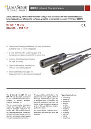
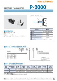
2-<strong>Color</strong> <strong>Non</strong>-<strong>Contact</strong><br />
<strong>Infrared</strong> <strong>Temperature</strong> <strong>Transmitters</strong><br />
for Industrial and Laboratory Applications<br />
• Self-contained sensor head “Infraducer ® ” with analog<br />
4-20mA linear and digital RS485 outputs<br />
• Through-lens sighting<br />
• Variable focussing<br />
• 0.5% accuracy<br />
• Fast response of 7.5 ms<br />
• Fiber optic version for harsh environments<br />
• 4 digit alpha numeric display<br />
• Remote configuration software<br />
• Single 24V power supply<br />
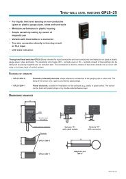
Model M770/770S<br />
through-lens sighting (M770S)<br />
Model M780 Fiber Optic Version<br />
for Harsh Environments<br />
Eye piece<br />
A digital alpha<br />
numeric display<br />
Visual sighting<br />
M770S rear panel<br />
Focussing knob<br />
(adjustable from<br />
rear panel)<br />
Output terminal<br />
strip<br />
Mikron M770/780 Series<br />
“Infraducer” is a registered trademark<br />
of Mikron <strong>Infrared</strong> Inc.<br />
Reticle defines<br />
exact area of<br />
temperature<br />
measurement
M770/780 2-color <strong>Infrared</strong> <strong>Temperature</strong> <strong>Transmitters</strong><br />
Innovative Design<br />
Mikron M770/780 “Infraducers” series represent another<br />
milestone in innovative infrared thermometry. Designed by<br />
integrating advanced non-parallax optical sighting with a fully<br />
digital electronics system in a single package providing unparalleled<br />
accuracy and speed for demanding industrial and scientific<br />
applications. A built-in 4-digit alpha numeric display located on<br />
the rear panel displays temperature and menu for selection of<br />
instrument initial settings. The linear analog 4-20mA and RS485<br />
digital outputs provide the convenience of long distance signal<br />
transmission for temperature measurement, control and data<br />
collection. The M770/780s’ unmatched array of protective<br />
accessories, demonstrate Mikron’s commitment to long-term<br />
trouble-free operation of these instruments.<br />
Universal Application<br />
The M770/780 “Infraducers” series has the ability to measure<br />
the temperature simultaneously in three different ways. This<br />
insures that all laws of radiation physics are observed for<br />
accurate measurements. If there is any inconsistency between<br />
readings, the smart microprocessor algorithm identifies the<br />
source of the discrepancy on the rear display for user‘s<br />
immediate correction. The RS485 output when connected<br />
to a PC allows correction of parameters remotely.<br />
Why 2-color <strong>Infrared</strong> Thermometry<br />
M770/M780 “Infraducers” series also utilizes the 2-color<br />
principle, in which the temperature measurement is made by two<br />
independent detectors with different but adjacent narrow band<br />
infrared filters. By ratioing the output of these two detectors, the<br />
temperature measurement becomes independent of emissivity<br />
and a number of other factors that during the measurement<br />
degrade the accuracy of conventional instruments. Thus,<br />
temperature measurement with the M770/780 are:<br />
• Unaffected by emissivity change for gray targets<br />
• Unaffected by dust and other contaminants in the field of view<br />
• Unaffected by varying target size (provides accurate reading with<br />
only 5% of target area within field of view)<br />
• Unaffected by dirty viewing window<br />
• Unaffected by small oscillating target within field of view<br />
Model M770S<br />
The M770S is housed in a compact, rugged, anodized aluminum<br />
housing about 200mm (8”) long. This self-contained sensor head<br />
incorporates a high quality, high resolution variable focus optical<br />
system that provides a sharp erect image of the target.<br />
Focussing is executed by turning the focusing knob on the rear<br />
panel of the instrument.<br />
The M770S enables precision pinpointing of small target areas.<br />
The user simply adjusts the instrument until the desired target is<br />
clear within the reticle. (See front cover).<br />
Model M770<br />
The M770 is identical to the M770S except it has no throughlens<br />
sighting and focusing is factory fixed for a pre-determined<br />
distance. This unit is only desirable for application where target<br />
is sufficiently large and pin pointing of measurement spot is<br />
not important.<br />
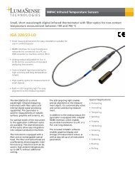
M780 for Inaccessible or<br />
Environmentally Severe<br />
Applications<br />
The fiber optics based M780<br />
“Infraducer” is recommended<br />
for areas where the<br />
following conditions exist:<br />
A. When direct sighting with<br />
the M770S is impossible due<br />
to obstructions. The flexibility<br />
of the fiber optics cable<br />
M780 rear panel<br />
overcomes this problem.<br />
B. Where RF or EMI interference is a problem, requiring the<br />
electronics to be placed at a safe distance from the source<br />
of interference.<br />
C. Where exceptionally high ambient temperatures exist. Fiber<br />
optic tips and lens assemblies can withstand temperatures up<br />
to 600°F (315°C) without cooling and up to 1000°F (540°C)<br />
with air cooling.<br />
D. Where corrosive environments prohibit the use of a<br />
conventional system.<br />
E. In vacuum applications where sighting through the window<br />
is difficult or impossible, a fiber optics lens assembly can be<br />
placed inside the vacuum vessel, using Mikron’s exclusive fiber<br />
optic feed-thorough bushing.<br />
F. When a non-electrical fiber optic version allows installation in<br />
hazardous locations.<br />
Application Assistance<br />
Many years of experience in solving unusual<br />
and difficult infrared temperature measurement<br />
problems qualifies our sales<br />
and application engineering staffs to<br />
offer solutions to the most challenging<br />
applications encountered in industry<br />
and science.<br />
Quality Assurance<br />
Reliability is never taken for granted<br />
at Mikron. Before final calibration,<br />
every “Infraducer” is tested and<br />
burned-in, rigorously subjected to<br />
a period of thermal cycling and<br />
vibration to insure the integrity of<br />
the instrument.<br />
Mikron maintains ISO 9001 certification<br />
with Factory Mutual with auditing<br />
interval of every 6 months.<br />
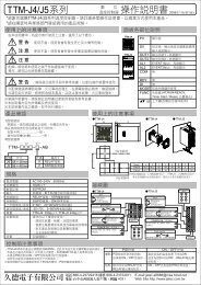
Aluminum housing to<br />
protect optics and<br />
electronics<br />
M770S<br />
2
Typical Applications<br />
The unique features of models M770/780 “Infraducers” makes<br />
this series ideal for a wide range of temperature measurement<br />
applications above 300°C (540°F). These include metal melting,<br />
Vacuum Melting<br />
heat treating, ore smelting, wire and rod forming, induction<br />
heating, vacuum furnaces, utility furnaces, glass furnaces, rotating<br />
kilns, crystal growing and RTP in the semiconductor industry.<br />
Crystal Growing<br />
M770S<br />
M770S<br />
Seed<br />
Crystal<br />
Melt<br />
Melt<br />
Sees through<br />
quartz or sapphire<br />
dirty windows<br />
Induction Coil<br />
Foundry<br />
Glass Furnaces<br />
Molten<br />
Glass<br />
M770S<br />
M770S<br />
Glass<br />
Gob<br />
Forehearth<br />
The use of fiber optic infrared thermometers for measurement<br />
and control of automatic induction heating systems is well<br />
M780 “Infraducer” Fiber Optic Version<br />
established. Further advantages of the M780 lie in its ability to<br />
accurately measure shiny surfaces.<br />
Aerospace<br />
Fiber optic<br />
cable<br />
M780<br />
Automotive<br />
Induction Coil<br />
This illustration<br />
indicates how model<br />
M780 can be used<br />
at multiple locations<br />
along the length of<br />
the process.<br />
Piston<br />
Ring<br />
OUT<br />
IN<br />
Lens<br />
Assembly<br />
Fiber Optic<br />
Cable<br />
M780<br />
Vacuum<br />
or high<br />
pressure<br />
bushing<br />
Semiconductor<br />
Quartz Window<br />
Halogen Lamps<br />
Reflector<br />
Semiconductor<br />
Wafer<br />
Enclosed Furnaces – In vacuum or high pressure furnaces<br />
often sighting through a window is difficult or undesirable. In<br />
this application a fiber optic lens assembly is placed inside the<br />
vessel, using a vacuum bushing feed through.<br />
M780<br />
Light Probe<br />
Flexible Fiber Optic Cable<br />
Enclosure<br />
RTP Chamber – Model 780 is designed for RTP applications. A<br />
high-speed measurement combined with custom designed sapphire<br />
probe allows silicon wafer temperature measurement with precision.<br />
3
How to Select an M770 or M770S “Infraducer”<br />
Selection Procedure:<br />
a. M770 – Fixed focus (no sighting)<br />
b. M770S – Variable focus, see through-lens sighting<br />
After choosing the desired model follow these 4 steps.<br />
1. Select the temperature range and units (C or F) from ranges<br />
listed. Insert ranges and units in Box 1 , filling in all blanks<br />
with zeros.<br />
2. Place letter “R” or “R1” in Box 2 for standard spectral<br />
response.<br />
3. Select signal output; (L) for standard 4-20mA linear and<br />
RS485 and insert in Box 3 .<br />
4. Select the correct operating distance.<br />
a. If you selected the M770 fixed focus model, specify the<br />
desired focus distance in writing (See Table 1 and optical<br />
resolution box below) and enter “U” in Box 4 .<br />
b. If you selected the focusable M770S read the section<br />
“Optical Resolution” below. Then choose the desired<br />
operating distance and insert the corresponding Code<br />
No. in Box 4 .<br />
Example<br />
The model chosen for the instrument indicated in the selection<br />
chart is the focusable M770S with through-lens sighting for<br />
a temperature range of 750° to 2000°C, standard spectral<br />
response of two narrow bands, analog 4-20mA linear and digital<br />
RS485 outputs and a focusable operating distance of 380mm<br />
(15”) to infinity with field of view ratio of 90:1.<br />
Optical Resolution<br />
Model M770S<br />
Three different lenses are available for the M770S. The one you<br />
should choose depends on the desired working distance of the<br />
unit. The first version is designed to measure temperature at<br />
distances of 380mm (15”) to infinity. The second version has a<br />
working range of 150mm (6”) to 380mm (15”). The third version<br />
is fixed to measure temperatures at a 50mm (2”) distance.<br />
Proper focussing is achieved by mounting the unit at the<br />
desired distance and adjusting the focussing knob on the rear<br />
panel of the instrument until the target comes into clear view in<br />
the reticle. When the target is in focus to the eye, it is also in<br />
focus to the detector. Reticle defines exact size and position of<br />
measurement spot.<br />
Model M770<br />
Exact Target Diameter determined by the formula:<br />
Focussed Distance (D)<br />
Target Diameter (d) =<br />
Field of View Ratio<br />
Target size (d)<br />
Distance (D)<br />
Example: M770, distance with 60:1 FOV ratio focussed at<br />
380mm (15”) distance<br />
D 380<br />
Minimum Target Size(d) = = = 6.4mm<br />
FOV ratio 60<br />
15”<br />
(or = = 0.25”)<br />
60<br />
4<br />
Selection Chart<br />
M770S 0 7 5 0 – 2 0 0 0 C R L<br />
1<br />
<strong>Temperature</strong> Range<br />
(see note 1)<br />
°C °F<br />
300-850* 572-1562*<br />
450-1200* 850-2200*<br />
Notes: 1. Special temperature ranges are available upon request.<br />
2. See table 1 for availability of standard fixed focus distances for a<br />
given FOV ratio.<br />
Table 1 – M770 Fixed Focus Distance<br />
Field of<br />
View Ratio<br />
30:1<br />
60:1<br />
90:1<br />
180:1<br />
Field of<br />
View Ratio<br />
60:1<br />
600-1400 1100-2550 60:1<br />
750-2000 1400-3600 90:1<br />
1000-3000 1800-5400 180:1<br />
Standard Fixed<br />
Focus Distance<br />
0.75m (30”)<br />
1.5m (60”)<br />
2.1m (90”)<br />
4.5m (180”)<br />
0<br />
C or F<br />
Minimum<br />
Focus Distance<br />
50mm (2”)<br />
150mm (6”)<br />
150mm (6”)<br />
380mm (15”)<br />
Table 2 – M770S<br />
Minimum target sizes are shown in the table below<br />
2<br />
Spectral<br />
Response<br />
CODE<br />
R1<br />
TWO<br />
NARROW<br />
BANDS<br />
NEAR<br />
R<br />
INFRARED<br />
Output<br />
Analog<br />
4-20mA<br />
Linear<br />
and<br />
Digital<br />
RS485<br />
CODE<br />
L<br />
3<br />
1<br />
4<br />
Operating<br />
Distance<br />
(see note 2)<br />
CODE<br />
380mm<br />
(15”) to 1<br />
infinity<br />
150mm<br />
(6”) to<br />
380mm<br />
(15”)<br />
50mm<br />
(2”) fixed<br />
Field of Version 1 Version 2 Version 3<br />
View Focus 15” Focus 6” Focus at<br />
Ratio to Infinity to 15” 50mm (2”)<br />
60:1<br />
6mm (0.24”) 2.5mm (0.10”) 0.8mm (0.03”)<br />
at 380mm (15”) at 150mm (6”) at 50mm (2”)<br />
90:1<br />
4mm (0.16”) 1.8mm (0.07”)<br />
at 380mm (15”) at 150mm (6”)<br />
N/A<br />
180:1<br />
2.1mm (0.1”) 0.8mm (0.03”)<br />
at 380mm (15”) at 150mm (6”)<br />
N/A<br />
How to Select an M780 “Infraducer”<br />
The selection process for the M780 is similar to that of the M770,<br />
with the additional requirements of the fiber optic feature. The<br />
selection steps are as follows:<br />
1. Select the temperature range and units (C or F) from ranges<br />
listed. Insert ranges and units in Box 1 , filling in all blanks<br />
with zeros.<br />
2. Place letter “R” or “R1” in Box 2 for standard spectral<br />
response.<br />
3. Select signal output; (L) for standard 4-20mA linear and<br />
RS485 and insert in Box 3 .<br />
4. Select the length of fiber optics cable and insert code number<br />
in Box 4 .<br />
5. Select the required lens assembly from the field of view<br />
diagrams and insert code number in Box 5 .<br />
2<br />
3
How To Select An M780 “Infraducer”<br />
Selection Chart<br />
M780<br />
0<br />
C or F<br />
0 7 5 0 – 2 0 0 0 C<br />
<strong>Temperature</strong> Range Field of Max. Fiber<br />
(see note 1) View Ratio Optic Length<br />
°C °F<br />
450-1200* 850-2400* 30:1 360cm (12’)<br />
600-1400 1100-2550 30:1 900cm (30’)<br />
750-2000 1400-3600 60:1 900cm ( 30’)<br />
1000-3000 1800-5400 90:1 900cm ( 30’)<br />
1<br />
2<br />
Spectral<br />
Response<br />
TWO<br />
NARROW<br />
BANDS<br />
NEAR<br />
INFRARED<br />
CODE<br />
R1<br />
R<br />
R<br />
Output<br />
Analog<br />
4-20mA<br />
Linear<br />
and<br />
digital<br />
RS485<br />
3<br />
CODE<br />
L<br />
/ /<br />
L S 1 2 0 6 0 S<br />
4<br />
Fiber Optic<br />
Cable<br />
Length<br />
cm Ft. CODE<br />
90 3 S03<br />
180 6 S06<br />
360 12 S12<br />
540 18 S18<br />
720 24 S24<br />
900 30 S30<br />
Special<br />
Length –<br />
(consult<br />
Mikron)<br />
SXX<br />
5<br />
Standard Focus Lens Assembly<br />
(see note 2)<br />
FOV FOCUS CODE<br />
30:1 30” 030S<br />
60:1 60” 060S<br />
90:1 90” 090S<br />
Standard Focus Distance<br />
FOV Ratio<br />
Field of View Diagrams<br />
Example<br />
30:1<br />
Min. Focusable<br />
Distance: 7.6cm (3.0”)<br />
60:1<br />
Min. Focusable<br />
Distance: 10cm (4.0”)<br />
DISTANCE IN.<br />
TARGET DIA. IN.<br />
TARGET DIA. CM<br />
DISTANCE CM<br />
DISTANCE IN.<br />
TARGET DIA. IN.<br />
TARGET DIA. CM<br />
DISTANCE CM<br />
DISTANCE IN.<br />
0<br />
.40<br />
1.0<br />
0<br />
0<br />
.40<br />
1.0<br />
0<br />
0<br />
30<br />
1.0<br />
2.5<br />
76<br />
60<br />
1.0<br />
2.5<br />
150<br />
90<br />
60<br />
2.5<br />
5.7<br />
140<br />
120<br />
2.5<br />
6.2<br />
300<br />
180<br />
The model number for the M780 “Infraducer”<br />
indicated in the boxes designates a sensor with a<br />
temperature range of 750° to 2000°C with an analog<br />
4-20mA linear and digital RS485 outputs using<br />
360cm (12’) length of fiber optics cable, a standard<br />
lens assembly with a field of view ratio of 60:1 at<br />
standard focus distance of 1500mm (60”).<br />
Notes: 1. Special ranges are available upon request.<br />
2. For non-standard focus distance see<br />
explanation in chart below.<br />
90:1<br />
Min. Focusable<br />
Distance: 15.2cm (6.0”)<br />
TARGET DIA. IN.<br />
TARGET DIA. CM<br />
DISTANCE CM<br />
.40<br />
1.0<br />
0<br />
1.0<br />
2.5<br />
230<br />
2.5<br />
6.4<br />
460<br />
<strong>Non</strong>-Standard Focus Distance<br />
When non-standard focus distance is desired, such as close focus,<br />
insert code”U” instead of “S” as the last digit in the model number<br />
specify focus distance in writing. Minimum target diameter is determined<br />
by the formula.<br />
Focussed Distance (D)<br />
Minimum Target diameter (d) =<br />
Field of View Ratio<br />
Target diameter (d)<br />
M780 Lens Assembly<br />
Fiber optic<br />
cable<br />
Distance (D)<br />
Example: Min. target diameter for focus distance of<br />
30cm (12”) and FOV ratio of 90:1, is<br />
30<br />
12<br />
Minimum Target diameter = 90 = 0.33cm or 90 = (0.13”)<br />
Lens assembly<br />
Mounting bracket<br />
5
Specifications<br />
M770/770S/780 Specifications<br />
Accuracy: ±0.5% of full scale , (1% for ranges marked *)<br />
Repeatability: 0.1% of full scale span<br />
<strong>Temperature</strong> Resolution: 1 °C/°F<br />
Spectral Response: One or two narrow bands near infrared<br />
region<br />
Sighting Methods: Through the lens sighting (M770S only)<br />
Working Distance: 15” to inf. (38cm to inf.)<br />
Close Focus Option: 6” to 15” or fixed at 2” (50mm)<br />
<strong>Temperature</strong> Display: Bright alpha numeric LED, 4 digits<br />
17.5mm (L) x 6mm (H) (0.7” x 0.25”)<br />
<strong>Temperature</strong> Mode: Current temperature, average<br />
temperature (up to 100 reading average), Peak with auto reset<br />
Speed of Response: 7.5 milliseconds for 95% of final<br />
reading. Adjustable to 1 second<br />
Slope: Adjustable from 0.800 to 1.200 in 0.001 steps<br />
Emissivity: Adjustable from 0.10 to 1.00 in 0.001 steps<br />
Menu Selection: By rear panel push buttons °C/°F, High/Low<br />
alarm, Average, Peak, Slope, Emissivity, Transmission Loss,<br />
<strong>Temperature</strong> span, Rate of temperature change, Peak and<br />
Hold, Speed of response and Internal instrument temperature<br />
Analog Output: 4-20mA (500Ω max load) isolated and<br />
scaleable<br />
Digital Output: Bi-directional RS485 communications<br />
(networkable)<br />
Relay: Programmable Relay Output, Type C <strong>Contact</strong>s<br />
Power Source: 19 to 35 V DC at 150 mA Typical<br />
Ambient <strong>Temperature</strong>:<br />
Operating: 0° to 50°C (32° to 122°F)<br />
With cooling jacket: up to 200°C (32° to 392°F)<br />
Storage: -40° to 80°C<br />
Housing Material: Hard anodized aluminum<br />
Housing: NEMA 4 (IP 65 IEC529) (with Protective Jacket)<br />
Dimensions: 178mm x 60mm (7” x 2.4”)<br />
Weight: 0.46kg (1 lb.)<br />
M770/770S Housing Dimensions<br />
178 (7.02)<br />
142.2 (5.60)<br />
60.5 (2.38) DIA<br />
Display<br />
44.5 (1.75)<br />
DIA<br />
30.5<br />
(1,200)<br />
DIA<br />
(2) Jam Nuts<br />
3/4-16 THD<br />
16<br />
(.62)<br />
Flexible<br />
Fiber Optic<br />
Cable<br />
21.5<br />
(.85)<br />
(M770S Only)<br />
Sighting eye<br />
piece<br />
Output terminal<br />
Focus knob<br />
38<br />
(1.5”)<br />
114 (4.50)<br />
M780 Standard<br />
Lens Assembly<br />
Note: M780 electronics is placed in same housing as M770. See above for details.<br />
Dimensions are mm (inch)<br />
Additional Specifications for M780 Only<br />
Lens Assembly Material: All lens assemblies are machined<br />
from solid stainless steel material.<br />
Lens Mounting: All mounting brackets and necessary<br />
hardware are supplied by Mikron.<br />
Fiber Optic Cable Material: Glass fibers in bundle form<br />
protected by flexible stainless steel sheath. Min. bend radius<br />
50mm (2”).<br />
Operating Ambient <strong>Temperature</strong>:<br />
a. Lens assembly: -60° to 315°C (-75° to 600°F)<br />
Lens with cooling jacket: up to 500°C (930°F)<br />
b. Fiber optic cable: stainless steel: -60° to 200°C<br />
(-75° to 392°F)<br />
Relative Humidity: 90% (non-condensing)<br />
Vibration: 3g’s any axis continuous<br />
Shock: 50g’s<br />
6<br />
Communication Software<br />
Optionally available is Mirdac software designed for M770/780<br />
“Infraducers” series by using the standard RS485 output for<br />
performing remote configuration settings, data collection and<br />
recording. Remote setting includes: Slope, Emissivity, Degrees<br />
C/F, Speed of response, <strong>Temperature</strong> span, High/low alarms,<br />
Peak and Hold, Rate of temperature change, Transmission Loss,<br />
Internal instrument temperature and Calibration adjustments. In<br />
addition the software allows;<br />
• Log data to disk in ASCII format with variable speed exportable<br />
to Excel, Lotus and Word<br />
• Graph of temperature versus time<br />
NIST Traceable Calibration Certificate<br />
Mikron infrared thermometers are supplied with calibration<br />
certificate at no charge. The additional assurance of a calibration<br />
certificate traceable to National Institute of Standard and<br />
Technology (NIST), is optionally available at additional cost.
Accessories<br />
Mikron has an incomparable array of accessories, too<br />
numerous to list here. The following is a selection of<br />
some of the more commonly used devices.<br />
Protective Jacket and End Cap<br />
The cast aluminum jacket and end cap protects the<br />
“Infraducer” from physical damage when located in environments<br />
of heavy industry and also dampens the effect of rapid<br />
ambient changes. The precision machining of the protective<br />
jacket allows for easy removal and replacement of the<br />
“Infraducer” with no loss of alignment. In high ambients when<br />
temperature exceeds the maximum rated temperature of the<br />
unit, the use of a protective jacket with cooling capability is<br />
mandatory. Extensive research and testing of the jacket assures<br />
uniform cooling along its entire length and simultaneously<br />
isolates the “Infraducer” from thermal influence. While air<br />
flow alone is sufficient for light cooling, water must be used<br />
for moderate and heavy cooling.<br />
To order specify PN 11609-7 no cooling.<br />
To order specify PN 11609-8 with cooling.<br />
Ambient <strong>Temperature</strong><br />
Gal/Hr. Liters/Hr.<br />
°F °C<br />
150 65 0.2 0.8<br />
200 95 0.6 2.3<br />
250 120 1.0 3.8<br />
300 150 2.0 7.6<br />
350 175 3.0 11.4<br />
400 205 4.0 15.2<br />
Air Purge and Cooling Assembly<br />
Though simple in outward appearance, this assembly performs<br />
very important functions—purging and localized cooling. Air<br />
purging of the optics is extremely important when airborne<br />
contaminants can build up on the lens and eventually “blind”<br />
the optical assembly.<br />
In contrast to many air purge systems currently in use which<br />
actually develop a negative pressure vortex and contribute to the<br />
build up of contaminants, the Mikron air purge assembly has<br />
been carefully engineered by incorporating a unique air director<br />
to insure laminar flow, in order to prevent contaminant build-up<br />
from occurring. A flow of only 75 CFH (2CMH) of normally<br />
clean industrial air will keep the optics clean under most<br />
conditions.<br />
The metal sight tube is designed for installations where it is<br />
desirable to augment the air purge and facilitate approximate<br />
aiming of the “Infraducer”.<br />
In addition, the cooling plate section of the air purge assembly<br />
allows the coolant to circulate in a chamber which allows cooling<br />
of “Infraducer” up to ambient temperature of 100°C (210°F).<br />
The air purge assembly depends upon the protective jacket for<br />
mounting.<br />
To order specify PN 11524-L.<br />
Aiming Flange Assembly<br />
For installations requiring durable mounting of the “Infraducer”<br />
while allowing for adjustment of the optical path to a maximum<br />
of 5° in any direction.<br />
To order specify PN 11649-2.<br />
OUTPUT<br />
CABLE<br />
MOUNTING<br />
BRACKET<br />
REMOVABLE<br />
CAP<br />
COOLANT<br />
OUT<br />
(JACKET)<br />
.50 (13) ø<br />
(4) MOUNTING HOLES EQ. SP.<br />
ON A 4.7500 (121) Ø B.C. 1/8 NPT<br />
COOLANT IN<br />
6.00 ø<br />
(152)<br />
2.31 ø<br />
(59)<br />
3.00<br />
(76)<br />
.45<br />
(11)<br />
1.00<br />
(25)<br />
AIR PURGE ASSY<br />
14.35<br />
(364)<br />
5.60<br />
(142)<br />
1/8 NPT<br />
COOLANT IN<br />
1/8 NPT<br />
COOLANT OUT<br />
3.25<br />
(83)<br />
REMOVABLE CAP<br />
COOLANT IN<br />
(JACKET)<br />
COOLANT OUT<br />
(ADDITIONAL)<br />
AIR PURGE<br />
ASSEMBLY<br />
SPRING LOADED<br />
AIMING FLANGE<br />
MOUNT<br />
PROTECTIVE<br />
COOLING<br />
JACKET<br />
COOLANT IN<br />
(ADDITIONAL)<br />
SIGHT TUBE<br />
AIR<br />
PURGE<br />
IN<br />
NOTES<br />
1. ALL CASTINGS AND FLANGES ARE<br />
ALUMINUM UNLESS OTHERWISE SPECIFIED<br />
2. ALL HARDWARES ARE STAINLESS STEEL<br />
3. ALL DIMENSIONS ARE IN INCHES (MM)<br />
AIR PURGE<br />
SIGHT TUBE<br />
MOUNTING FLANGE<br />
ADJUSTABLE SPRINGS<br />
1.90 ø<br />
(48)<br />
ANGLE OF<br />
ADJUSTMENT<br />
(X-Y) AXIS<br />
10˚<br />
1/8 NPT AIR<br />
PURGE IN<br />
1/8 NPT<br />
COOLANT OUT<br />
PROTECTIVE JACKET<br />
COOLING (OPTIONAL)<br />
2.81 ø<br />
(71)<br />
2.88 ø<br />
(73)<br />
1.94<br />
1.50<br />
(49)<br />
(38) 1/2 NPT<br />
2.50<br />
(63)<br />
OUTPUT CABLE<br />
BUSHING<br />
9.41<br />
(239)<br />
1/4 - 20 TAP X .375 DP.<br />
(2) HOLES<br />
MOUNTING SURFACE<br />
7
Accessories<br />
Removable Window<br />
Assembly<br />
Frequently in industrial application<br />
the outgassing from process<br />
may penetrate the instrument<br />
sight tube and deposit on optical<br />
assembly, or air supply may be<br />
shut off inadvertently resulting<br />
in degrading the temperature<br />
measurement. The removable<br />
window assembly is exclusively designed to overcome this<br />
problem. The window assembly is mounted in front of protective<br />
jacket. The maintenance personnel can periodically remove the<br />
window by simply pulling it from a slot, cleaning the window if<br />
necessary and inserting the window back into the slot. To order<br />
specify PN 14925-1.<br />
1<br />
/8 NPT air purge in<br />
M780 Air<br />
Purge/Cooling<br />
Assembly<br />
An air purge is mandatory<br />
in most industrial applications<br />
to keep the lens<br />
Air purge assembly<br />
assembly clean for<br />
extended periods of time. The air purge is designed to be effective<br />
with filtered plant air which does not need to be instrument<br />
quality. An air flow of 2.8m 3 /Hr. (100ft 3 /Hr.) is sufficient for most<br />
applications. The air purge assembly will also provide cooling if<br />
the lens assembly is likely to be exposed to ambient temperatures<br />
up to 400°C (750°F). The overall length of this assembly is<br />
168mm (6.6”). The diameter of the air purge sight tube is 19mm<br />
(0.75”). To order specify PN 14296-1.<br />
Atmosphere<br />
Fiber optic<br />
cable out<br />
Base plate<br />
Vacuum Bushing<br />
Vacuum<br />
Fiber optic<br />
cable in<br />
Fiber Optic Vacuum<br />
Bushing<br />
In vacuum applications where<br />
sighting through a window is<br />
difficult or impossible, a fiber<br />
optic cable can be placed<br />
inside the vacuum up to<br />
10- 6 torr with the aid of this<br />
bushing. The bushing holds a<br />
bundle of fiber optics which is sealed for high vacuum applications.<br />
This system seals the vacuum and allows for removal of<br />
the cable on either side of the busing without affecting the<br />
integrity of the vacuum seal. To order specify PN 12506.<br />
Incoming<br />
radiation<br />
30mm<br />
(1.2”)<br />
90°<br />
Right Angle Viewing<br />
Attachment<br />
Physical limitations often prohibit<br />
conventional mounting of lens<br />
assemblies. The right angle<br />
viewing attachment provides a<br />
means for rotating the physical;<br />
aspect of the lens assembly by<br />
90° while viewing the desired<br />
target. By using the right angle viewing attachment the lens<br />
assembly length of 114mm (4.5”) is reduced to 30mm (1.2”).<br />
right angle viewing is only available for standard and focusable<br />
lens assembly. To order specify PN 16376-2.<br />
Fiber Optic Target Illuminator<br />
Mikron offers a fiber optic illuminator<br />
for precision illumination of the target<br />
areas when used in conjunction with<br />
fiber optics and lens assembly. This<br />
illuminator can conveniently be taken<br />
to lens assembly location for precision<br />
refocusing or identification of<br />
AC Line Operation target area.<br />
To order:<br />
Specify PN 12110-1A for 115 VAC<br />
Specify PN 12110-2B for 220 VAC<br />
Specify PN 12110-3C for 100 VAC<br />
Power Supply<br />
Power Supply<br />
right<br />
angle<br />
viewing<br />
attachment<br />
Lens<br />
assembly<br />
Power supply for M770/780<br />
“Infraducer” is a low profile, sealed,<br />
switching power supply with universal<br />
AC input voltage and frequency.<br />
Maximum in-rush current of 15A<br />
protective power supply when a<br />
momentary short circuit occurs. To<br />
order specify PN 18712-1.<br />
Input voltage: 90 - 250 VAC<br />
Frequency: 47 to 63Hz<br />
Output Voltage: 24V at 0.7 Amps<br />
Operating Temp: 0° to 50°C (32° to 122°F)<br />
Connection: 5P/9.5mm pitch terminal block<br />
Dimensions: 98mm (H) x 97mm (W) x 35mm (H)<br />
(3.9” x 3.8” x 1.4”)<br />
Made in U.S.A.<br />
The M770/780 “Infraducers” series are designed and built by Mikron, the leading innovator in infrared technology, manufacturing<br />
facility is located in Oakland, New Jersey, USA.<br />
Warranty<br />
All Model M770/780 “Infraducers” series are covered for all defective material and workmanship for one full year after shipment.<br />
ISO 9001