unit 2 design of single point cutting tools
unit 2 design of single point cutting tools
unit 2 design of single point cutting tools

You also want an ePaper? Increase the reach of your titles
YUMPU automatically turns print PDFs into web optimized ePapers that Google loves.
UNIT 2 DESIGN OF SINGLE POINT CUTTING<br />
TOOLS<br />
Design <strong>of</strong> Single<br />
Point Cutting Tools<br />
Structure<br />
2.1 Introduction<br />
Objectives<br />
2.2 Design <strong>of</strong> Tool Shank<br />
2.3 Design <strong>of</strong> Tool Geometry<br />
2.3.1 Basic Elements<br />
2.3.2 Influence <strong>of</strong> Various Angles on Tool Design<br />
2.4 Selection <strong>of</strong> Tool Material<br />
2.4.1 Desirable Properties <strong>of</strong> Tool Material<br />
2.4.2 Characteristics <strong>of</strong> Some Important Tool Material<br />
2.5 Calculation <strong>of</strong> Forces and Design for Cutting Forces<br />
2.6 Summary<br />
2.7 Key Words<br />
2.8 Answers to SAQs<br />
2.1 INTRODUCTION<br />
Design <strong>of</strong> <strong>single</strong> <strong>point</strong> <strong>cutting</strong> tool is an important aspect <strong>of</strong> tool engineering. This <strong>unit</strong><br />
deals with the <strong>design</strong> <strong>of</strong> tool shank, <strong>design</strong> <strong>of</strong> <strong>single</strong> <strong>point</strong> <strong>cutting</strong> tool, and various forces<br />
involved during machining <strong>of</strong> the workpiece. Strength and rigidity <strong>of</strong> tool is also taken<br />
into account while <strong>design</strong>ing <strong>single</strong> <strong>point</strong> <strong>cutting</strong> tool.<br />
Objectives<br />
After studying this <strong>unit</strong>, you should be able to<br />
• <strong>design</strong> tool shank,<br />
• <strong>design</strong> <strong>single</strong> <strong>point</strong> <strong>cutting</strong> tool,<br />
• select appropriate tool material, and<br />
• calculate and analyze the forces acting on tool.<br />
2.2 DESIGN OF TOOL SHANK<br />
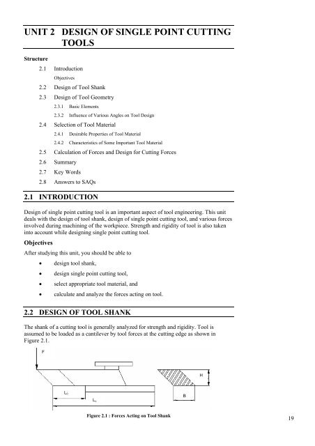
The shank <strong>of</strong> a <strong>cutting</strong> tool is generally analyzed for strength and rigidity. Tool is<br />
assumed to be loaded as a cantilever by tool forces at the <strong>cutting</strong> edge as shown in<br />
Figure 2.1.<br />
F<br />
H<br />
L 0<br />
L c<br />
B<br />
Figure 2.1 : Forces Acting on Tool Shank<br />
19
Design <strong>of</strong> Cutting<br />
Tools and Holding<br />
Devices<br />
20<br />
Figure 2.2 : Deflections and Frequency <strong>of</strong> Chatter for Several Overhung Values<br />
The notations used in <strong>design</strong> <strong>of</strong> shank is given below :<br />
F = Permissible tangential force during machining, N<br />
f = Chatter frequency, cycle per second (c.p.s)<br />
H = Depth <strong>of</strong> shank, mm<br />
B = Width <strong>of</strong> shank, mm<br />
L 0 = Length <strong>of</strong> overhung, mm<br />
d = Deflection <strong>of</strong> shank, mm<br />
E = Young’s modulus <strong>of</strong> material, N/mm 2<br />
I = Moment <strong>of</strong> inertia, mm 4<br />
h c = Height <strong>of</strong> centres, mm<br />
σ ut = Ultimate tensile strength, N/mm 2<br />
σ per = Permissible stress <strong>of</strong> shank material, N/mm 2<br />
L c = Length <strong>of</strong> centres, mm<br />
The main <strong>design</strong> criterion for shank size is rigidity. The deflection at the <strong>cutting</strong> edge is<br />
limited to a certain value depending on the size <strong>of</strong> machine, <strong>cutting</strong> conditions and tool<br />
overhung. The tool overhung (L 0 ) is related also to the shank size as well as to the end<br />
support conditions. Figure 2.2 shows graph <strong>of</strong> the amplitude and frequency <strong>of</strong> chatter for<br />
several overhung values. It is seen from Figure 2.2 that only below L 0 /H = 2, the<br />
amplitude is practically zero. The recommended value <strong>of</strong> (L 0 /H) lies between 1.2 and 2.<br />
For the given value <strong>of</strong> chatter frequency f, the shank deflection can be calculated from<br />
the (Eq. 2.1) given as follows.<br />
where, d is deflection in mm.<br />
(15.76)<br />
f = c.p.s. . . . (2.1)<br />
d<br />
Now as chatter frequency ranges from 80 to 160 c.p.s.,<br />
Let<br />
f = 100 c.p.s<br />
d = (15.76/100) 2 ≅ 0.025 mm . . . (2.2)
The permissible deflection <strong>of</strong> shanks ranges from 0.025 mm for finish cuts to 0.9 mm for<br />
rough cuts. Considering shank as a cantilever,<br />
Design <strong>of</strong> Single<br />
Point Cutting Tools<br />
d =<br />
3<br />
FL0<br />
3EI<br />
3<br />
3<br />
0<br />
3<br />
FL0 ⎛ 12 ⎞ 4FL<br />
d = ⎜ ⎟ =<br />
3<br />
3E<br />
⎝ BH ⎠ EBH<br />
= 0.025 mm<br />
It can be noted that the same value <strong>of</strong> d has been obtained from Eq. (2.2) also.<br />
The shank size can be estimated with respect to machine tool size by the following<br />
method :<br />
(a)<br />
(b)<br />
The force F for given size <strong>of</strong> lathe is given by<br />
F = f × t × C<br />
where, f is the feed in mm,<br />
t is the depth <strong>of</strong> cut in mm, and<br />
C is <strong>cutting</strong> force constant.<br />
. . . (2.3)<br />
Nicolsons Manchester experiments have set a standard area <strong>of</strong> cut for lathe<br />
<strong>design</strong> given by<br />
Let,<br />
A c = f × t<br />
f = h c /180 mm and t = h c /25 mm<br />
h h<br />
A<br />
c c<br />
c<br />
= ×<br />
180 25<br />
2<br />
h c<br />
where, h c is height <strong>of</strong> centre in mm,<br />
= mm 2<br />
4500<br />
Let, σ ut = 440 N/mm 2<br />
C = 4σ ut<br />
= 4 × 400 = 1760 N/mm 2<br />
When<br />
F =<br />
2<br />
h c<br />
2 2<br />
mm × 1760 N/mm<br />
4500<br />
2<br />
= 0.4 h c N<br />
On substituting the value <strong>of</strong> F =<br />
2<br />
0.4hc<br />
in Eq. (2.3), we get<br />
d<br />
=<br />
2 3<br />
c L 0<br />
3<br />
4(0.4 h )<br />
EBH<br />
4(0.4 hc<br />
)<br />
0.025 =<br />
EBH<br />
As, d = 0.025 from Eq. (2.2). Thus,<br />
2 3<br />
L 0<br />
3<br />
B = 0.6 H for rectangular shanks<br />
2 3<br />
c L 0<br />
3<br />
(1.6 h )<br />
=<br />
EBH<br />
21
Design <strong>of</strong> Cutting<br />
Tools and Holding<br />
Devices<br />
Then,<br />
h<br />
H<br />
2<br />
c<br />
4<br />
= 0.6<br />
0<br />
L 3<br />
ED<br />
Let<br />
L 0<br />
= 3 mm, E = 200 kN/mm<br />
2<br />
and d = 0.025 mm, (From Eq. (2.2))<br />
On substituting these values in above equation, i.e.<br />
2<br />
h c<br />
4<br />
H<br />
ED<br />
= 0.6 , we get<br />
L<br />
0<br />
3<br />
H<br />
2<br />
h c<br />
= 1000 mm − 2<br />
4<br />
Table 2.1 shows the standard shank size according to this rule.<br />
Table 2.1<br />
Height <strong>of</strong> Centres<br />
h c (mm)<br />
H (mm)<br />
Shank Size<br />
B (mm)<br />
250 20 12<br />
300 30 20<br />
350 40 25<br />
Usually the shank size is also checked for strength.<br />
Noting,<br />
FL<br />
1<br />
6<br />
2<br />
0 = BH σ 1<br />
6FL<br />
0<br />
∴ σ 1 =<br />
2<br />
BH<br />
When the effect <strong>of</strong> F x included,<br />
6FL<br />
σ=σ +σ = +<br />
BH<br />
0 0<br />
1 2 6 F<br />
2 x 2<br />
L<br />
HB<br />
F x = Component <strong>of</strong> force F acting in x direction (in Newton)<br />
F x = 0.3 to 0.40 F<br />
. . . (2.4)<br />
6FL0<br />
⎛0.4 ⎞ ⎛ 1 ⎞<br />
Hence, σ = ⎜ ⎟+<br />
⎜ ⎟ per<br />
BH ⎝ B ⎠ ⎝ H ⎠ < σ . . . (2.5)<br />
This can be expressed as<br />
F<br />
⎧<br />
⎫<br />
⎪ BH ⎛ 1 ⎞<br />
⎪ σ<br />
= ⎨ +<br />
0.4<br />
⎜ ⎟⎬<br />
⎪⎛ ⎞ ⎝H<br />
⎠⎪<br />
6L<br />
⎪<br />
⎜ ⎟<br />
⎩⎝<br />
B ⎠ ⎪⎭<br />
per<br />
0<br />
. . . (2.6)<br />
where, F is permissible tangential force during machining.<br />
The maximum depth <strong>of</strong> shank (H max ) must be less than the value h k as shown<br />
in Table 2.2.<br />
22<br />
Table 2.2
h k (mm) 11 14 22 28 45 56<br />
H max (mm) 10 12 20 25 40 50<br />
Design <strong>of</strong> Single<br />
Point Cutting Tools<br />
SAQ 1<br />
(a)<br />
(b)<br />
Which parameters are considered for <strong>design</strong>ing tool shank<br />
How one can <strong>design</strong> tool shank<br />
2.3 DESIGN OF TOOL GEOMETRY<br />
2.3.1 Basic Elements<br />
The basic elements <strong>of</strong> tool are shown in Figure 2.3.<br />
Error!<br />
End Cutting Edge<br />
Tool Point<br />
Nose<br />
C e<br />
Radius<br />
Face<br />
Side Cutting Edge<br />
α b<br />
θ e<br />
Heel<br />
Lip Angle<br />
Shank<br />
Flank<br />
θ s<br />
Cutting Angle<br />
Base<br />
Figure 2.3 : Single Point Cutting Tool<br />
Symbol used in figure are :<br />
α b – Back rake angle<br />
α s – Side rake angle<br />
θ e – End relief angle<br />
θ s – Side relief angle<br />
C e – End <strong>cutting</strong> edge angle<br />
C s – Side <strong>cutting</strong> edge angle<br />
Size<br />
It is determined by the width <strong>of</strong> shank, height <strong>of</strong> shank and overall length.<br />
Shank<br />
Shank is main body <strong>of</strong> a tool. It is held in a holder.<br />
23
Design <strong>of</strong> Cutting<br />
Tools and Holding<br />
Devices<br />
Flank<br />
Heel<br />
Base<br />
Face<br />
Flank is the surface or surfaces below and adjacent to <strong>cutting</strong> edge.<br />
Heel is intersection <strong>of</strong> the flank and base <strong>of</strong> the tool.<br />
Base is the bottom part <strong>of</strong> the shank. It takes the tangential force <strong>of</strong> <strong>cutting</strong>.<br />
Face is surface <strong>of</strong> tool on which chip impinges when separated from workpiece.<br />
Cutting Edge<br />
Cutting edge is the edge <strong>of</strong> that face which separates chip from the workpiece. The<br />
total <strong>cutting</strong> edge consists <strong>of</strong> side <strong>cutting</strong> edge, the nose and end <strong>cutting</strong> edge.<br />
Tool Point<br />
The Nose<br />
Neck<br />
That part <strong>of</strong> tool, which is shaped to produce the <strong>cutting</strong> edge and the face.<br />
It is the intersection <strong>of</strong> side <strong>cutting</strong> edge and end <strong>cutting</strong> edge.<br />
Neck is the small cross section behind the <strong>point</strong>.<br />
Side Cutting Edge Angle<br />
The angle between side <strong>cutting</strong> edge and side <strong>of</strong> the tool shank is called side<br />
<strong>cutting</strong> edge angle. It is also called as lead angle or principle <strong>cutting</strong> angle.<br />
End Cutting Edge Angle<br />
The angle between the end <strong>cutting</strong> edge and a line perpendicular to the shank <strong>of</strong><br />
tool is called end <strong>cutting</strong> edge angle.<br />
Side Relief Angle<br />
The angle between the portion <strong>of</strong> the side flank immediately below the side <strong>cutting</strong><br />
edge and line perpendicular to the base <strong>of</strong> tool measured at right angles to the side<br />
flank is known as side relief angle. It is the angle that prevents interference, as the<br />
tool enters the work material.<br />
End Relief Angle<br />
End relief angle is the angle between the portion <strong>of</strong> the end flank immediately<br />
below the end <strong>cutting</strong> edge and the line perpendicular to the base <strong>of</strong> tool, measured<br />
at right angles to end flank. It is the angle that allows the tool to cut without<br />
rubbing on the workpiece.<br />
Back Rake Angle<br />
The angle between face <strong>of</strong> the tool and a line parallel with the base <strong>of</strong> the tool,<br />
measured in a perpendicular plane through the side <strong>cutting</strong> edge is called back rake<br />
angle. It is the angle which measures the slope <strong>of</strong> the face <strong>of</strong> the tool from the nose<br />
toward the rear. If the slope is downward toward the nose, it is negative back rake<br />
angle. And if the slope is downward from the nose, it is positive back rake angle. If<br />
there is not any slope, back rake angle is zero.<br />
Side Rake Angle<br />
24
The angle between the face <strong>of</strong> the tool and a line parallel with the base <strong>of</strong> the tool,<br />
measured in a plane perpendicular to the base and side <strong>cutting</strong> edge is called side<br />
rake angle. It is the angle that measures the slope <strong>of</strong> the tool face from <strong>cutting</strong><br />
edge. If the slope is towards the <strong>cutting</strong> edge, it is negative side rake angle. If the<br />
slope is away from the <strong>cutting</strong> edge, it is positive side rake angle.<br />
Design <strong>of</strong> Single<br />
Point Cutting Tools<br />
All the tool angles are taken with reference to the <strong>cutting</strong> edge and are, therefore,<br />
normal to the <strong>cutting</strong> edge. A convenient way to specify tool angle is by use <strong>of</strong> a<br />
standardized abbreviated system called tool signature. Sometimes it is also called<br />
as tool character. Tool signature also describes how the tool is positioned in<br />
relation to the workpiece.<br />
The signature for <strong>single</strong> <strong>point</strong> tool is listed in the order as rake angles (back and side),<br />
relief angles (end and side), <strong>cutting</strong> edge angles (end and side) and nose radius.<br />
Example 2.1<br />
Solution<br />
Tool signature <strong>of</strong> High speed steel tool: 0-7-7-7-15-15-0.5<br />
This implies that HSS tool has<br />
Back rake angle = 0°,<br />
Side rake angle = 7°,<br />
End relief angle = 7°,<br />
Side relief angle = 7°,<br />
End <strong>cutting</strong> edge angle = 15°,<br />
Side <strong>cutting</strong> edge angle = 15°, and<br />
Nose radius = 0.5 mm.<br />
2.3.2 Influence <strong>of</strong> Various Angles on Tool Design<br />
Back Rake Angle<br />
The rake angle <strong>of</strong> <strong>single</strong> <strong>point</strong> <strong>cutting</strong> tool is useful in determining the direction <strong>of</strong><br />
chip flow across the face <strong>of</strong> the tool.<br />
(a)<br />
(b)<br />
(c)<br />
(d)<br />
A positive back rake angle is responsible to move the chip away from<br />
the machined workpiece surface.<br />
The tool penetrates the workpiece easily and tends to shear the<br />
material <strong>of</strong>f rather than compressing. So the <strong>cutting</strong> efficiency is best<br />
with positive back rake angle.<br />
Forces and power consumption reduces with increase in positive back<br />
rake angle.<br />
If positive back rake angle increases, resisting area <strong>of</strong> tool decreases.<br />
Generally, for s<strong>of</strong>ter workpiece, back rake angle <strong>of</strong> 25° to 30° is preferable and for harder<br />
workpiece back rake angle <strong>of</strong> 7° to 10° is preferable. Negative back rake angle is<br />
preferable for carbide tool. Carbide <strong>tools</strong> are very brittle in nature, so deformation occurs<br />
if we provide positive back rake angle. To avoid deformation, negative back rake angle is<br />
provided.<br />
Positive back rake angle is used for machining low tensile strength and non ferrous<br />
materials. They are also used during machining <strong>of</strong> long/small diameter shafts or material<br />
that is work hardened during machining. Negative back rake angles are used for<br />
machining high tensile strength material, heavy feed and interrupted cuts.<br />
Side Rake Angle<br />
25
Design <strong>of</strong> Cutting<br />
Tools and Holding<br />
Devices<br />
Side rake angle should be positive. The significance <strong>of</strong> side rake angle is that it is<br />
used to avoid rubbing action between tool and workpiece.<br />
Relief Angle<br />
The main significance <strong>of</strong> relief angle is that it prevents rubbing action below<br />
<strong>cutting</strong> edge. Small relief angle gives maximum support below the <strong>cutting</strong> edge<br />
and is necessary while machining hard and strong workpiece. Too much relief<br />
angle weakens the <strong>cutting</strong> edge and failure <strong>of</strong> tool may takes place. Relief angles<br />
generally lie between 5° to 15°.<br />
Side Cutting Edge Angle<br />
It may vary from 0 to 90°. On increasing side <strong>cutting</strong> edge angle, the full length <strong>of</strong><br />
<strong>cutting</strong> edge is not in contact with workpiece when the tool enters the cut. The tool<br />
takes a little shock load and gradually reaches the full depth <strong>of</strong> cut without any<br />
impact.<br />
If side <strong>cutting</strong> edge angle is 0°, the full length <strong>of</strong> <strong>cutting</strong> edge is in touch with<br />
workpiece at once and produces severe initial shock. If side <strong>cutting</strong> edge angle is<br />
less, forces on tool will reduce as a result <strong>of</strong> which less power consumption occur.<br />
Also with increase in side <strong>cutting</strong> edge angle, surface finish increases and<br />
vice-versa.<br />
End Cutting Edge Angle<br />
End <strong>cutting</strong> edge angle vary from 4° to 30°. End <strong>cutting</strong> edge angle prevents<br />
rubbing between the end <strong>of</strong> the tool and the workpiece. If end <strong>cutting</strong> edge angle is<br />
less, it will cause vibration because <strong>of</strong> excessive tool contact with workpiece. With<br />
end <strong>cutting</strong> edge angle, surface finish decreases and vice-versa.<br />
Nose Radius<br />
SAQ 2<br />
Nose radius is provided to increase strength <strong>of</strong> tip <strong>of</strong> the tool. This is done by<br />
thinning the chip where it approaches tip <strong>of</strong> tool and by enlarging the chip over a<br />
larger area <strong>of</strong> the <strong>point</strong>. It is also provided to increase the surface finish. If the<br />
radius is more, the surface finish will be good. But due to too large nose radius,<br />
contact between tool and workpiece increases, which in turn increase friction.<br />
Thus, power consumption increases, along with increase in vibration and chatter<br />
occurs.<br />
(a)<br />
(b)<br />
(c)<br />
Define the basic elements <strong>of</strong> tool geometry.<br />
What do you understand by tool signature Illustrate with an example.<br />
How back rake angle influences the tool <strong>design</strong><br />
2.4 SELECTION OF TOOL MATERIAL<br />
26<br />
The tool engineer is required to select material for variety <strong>of</strong> products such as <strong>cutting</strong><br />
<strong>tools</strong>, jigs, punches, dies, special machine etc. A tool engineer must possess the<br />
knowledge <strong>of</strong> these materials and understand their properties. In addition, the various<br />
aspects <strong>of</strong> tooling, material cost, fabrication, manufacturing methods and the proper<br />
functioning <strong>of</strong> product should be considered.<br />
2.4.1 Desirable Properties <strong>of</strong> Tool Material<br />
The desirable properties <strong>of</strong> tool material are as follows :<br />
Wear Resistance
Wear resistance should be as high as possible. Wear <strong>of</strong> tool is caused by abrasion,<br />
adhesion and diffusion. Wear resistance refers to the ability <strong>of</strong> tool material to<br />
retain its sharpness and shape for longer duration while machining is continued.<br />
Hot Hardness<br />
Toughness<br />
It is the measure <strong>of</strong> the ability <strong>of</strong> tool material to retain its hardness at high<br />
temperature. Hot hardness should be as high as possible especially at high<br />
temperature.<br />
It is the ability <strong>of</strong> material to absorb energy and deform plastically before failure<br />
and fracture. Tougher the material more is the ability to withstand external load,<br />
impact and intermittent cuts. Hence, toughness should be as high as possible.<br />
Coefficient <strong>of</strong> Thermal Expansion<br />
Hardness<br />
Coefficient <strong>of</strong> thermal expansion determines the influence <strong>of</strong> thermal stresses and<br />
thermal shocks on a material. It should be as low as possible so that tool does not<br />
get distorted after heat treatment, and remains easy to regrind and also easy to weld<br />
to the tool holder. Carbide have lower coefficient <strong>of</strong> thermal expansion than high<br />
speed steel and they develop lower thermal stress but are more sensitive to thermal<br />
shock because <strong>of</strong> their brittleness.<br />
It is the ability <strong>of</strong> material to resist the penetration, scratching, abrasion or <strong>cutting</strong>.<br />
Hardness <strong>of</strong> tool material should be as high as possible. Generally it should be<br />
higher than workpiece.<br />
Thermal Conductivity<br />
It should be as high as possible with a view to remove the heat quickly from chip<br />
tool interface.<br />
2.4.2 Characteristics <strong>of</strong> Some Important Tool Material<br />
Following are the tool materials in increasing order <strong>of</strong> their hardness :<br />
High Carbon Steel<br />
These are usually plain carbon steel containing 0.6 to 1.5 % C. Method <strong>of</strong><br />
fabrication for High Carbon Steel (HCS) is forging. HCS has hot hardness<br />
temperature <strong>of</strong> about 250°C. Also, its maximum <strong>cutting</strong> velocity is about 5 m/min.<br />
Hence, HCS is generally used for machining s<strong>of</strong>t materials like aluminum, copper,<br />
magnesium etc. HCS is harder and the cheapest tool material.<br />
High Speed Steel<br />
High Speed Steel (HSS) is usually carbon steel containing 1.5 to 2% carbon, 18 %<br />
tungsten, 4% chromium, 1% vanadium and rest is iron. Tungsten is added to<br />
increase hardness. Chromium is added to increase hot hardness. Vanadium is<br />
added to increase wear resistance. Method <strong>of</strong> fabrication for HSS is forging.<br />
Cutting velocity <strong>of</strong> HSS is 40-60 m/min. It gives higher speed than HCS. Hot<br />
hardness temperature <strong>of</strong> HSS is about 600°C.<br />
Sometimes 18% molybdenum is added instead <strong>of</strong> tungsten to increase the wear<br />
resistance <strong>of</strong> tool. Then this HSS is called as molybdenum based HSS. But<br />
tungsten based HSS is commonly used. HSS has only disadvantage that during<br />
machining <strong>of</strong> pure carbon work material, diffusion <strong>of</strong> carbon atoms into iron is<br />
much more because iron has stronger affinity to attract carbon.<br />
Stellite<br />
These are non-ferrous cast alloys. Stellite contains 40-45% cobalt, 30% chromium,<br />
14-25% tungsten and 2% carbon. Method <strong>of</strong> fabrication for stellite is casting. Its<br />
Design <strong>of</strong> Single<br />
Point Cutting Tools<br />
27
Design <strong>of</strong> Cutting<br />
Tools and Holding<br />
Devices<br />
28<br />
hot hardness temperature is about 800°C. Its hardness is same as that <strong>of</strong> HSS. It is<br />
a substitute for HSS during machining <strong>of</strong> pure carbon work material.<br />
Carbide<br />
Carbides are either tungsten carbide or cemented carbide. It contains 85-95%<br />
tungsten carbide and 5-15% cobalt. Hot hardness temperature <strong>of</strong> carbide materials<br />
is about 1000°C, and its <strong>cutting</strong> speed is 10 times greater than HSS. Since the cost<br />
is high, hence only tip is made by carbide, and regrinding is also not possible.<br />
Fabrication for carbide is carried out by employing powder metallurgical<br />
techniques.<br />
Ceramics<br />
These are also called as cemented oxide. Its major constituent is aluminum oxide<br />
and hot hardness temperature is about 1200°C. It also has higher <strong>cutting</strong> speed <strong>of</strong><br />
about 300 to 400 m/min. It has better resistance to abrasion than cemented carbide.<br />
It also exhibits low coefficient <strong>of</strong> friction with most <strong>of</strong> work materials. These are<br />
used for higher production rate and for continuous operation only. The<br />
disadvantages <strong>of</strong> ceramic are very low toughness and highly brittle in nature.<br />
Fabrication for ceramic is done through powder metallurgical techniques.<br />
Cermets<br />
This is combination <strong>of</strong> ceramic and metal. It is substitute for ceramics. It contains<br />
90% ceramics and 10% nickel. The method employed for fabrication <strong>of</strong> cermet is<br />
also powder metallurgical technique. Its hot hardness temperature is about 1000°C<br />
and <strong>cutting</strong> speed is about 250 m/min. Cermet gives better toughness than ceramic.<br />
It gives very good wear resistance.<br />
Diamond<br />
Diamond possesses all the desirable characteristics but has very high cost.<br />
Diamond is made by graphitization technique. Its hot hardness temperature is<br />
about 2000°C. Its hardness is higher than any other material. It is chemically inert<br />
and has high thermal conductivity. Its <strong>cutting</strong> speed is about 500 m/min. Diamond<br />
is extensively used for machining <strong>of</strong> non-ferrous alloys such as aluminum,<br />
magnesium, copper, brass etc. Diamond is not used for machining <strong>of</strong> ferrous<br />
material because diamond is basically pure carbon and diffusion <strong>of</strong> carbon into<br />
iron takes place due to affinity <strong>of</strong> iron atoms toward carbon.<br />
Cubic Boron Nitride<br />
Cubic Boron Nitride consists <strong>of</strong> atoms <strong>of</strong> boron and nitrogen. It is hardest material<br />
next to diamond. It is substitute for diamond during machining <strong>of</strong> ferrous alloys. It<br />
has high hardness and thermal conductivity.<br />
UCON<br />
It is combination <strong>of</strong> columbium, titanium and tungsten. It contains 50%<br />
columbium, 30% titanium and 20% tungsten. Method <strong>of</strong> fabrication is rolling. Its<br />
hardness is 2500 to 3000 Vickers. The speed range for UCON is 250 to 500 m/min<br />
<strong>of</strong> steel <strong>of</strong> 200 BHN. Cost <strong>of</strong> UCON is higher than diamond and is used only for<br />
very hard material. It has excellent shock resistance, resistance to diffusion and<br />
adhesion wear.<br />
Sialon<br />
It contains silicon, aluminum, oxygen and nitrogen. It is even costlier than ucon.<br />
Sialon is used during machining <strong>of</strong> interrupted cuts. Sialon tips are used for<br />
machining <strong>of</strong> aerospace alloys.<br />
SAQ 3<br />
(a)<br />
(b)<br />
What are the desirable properties <strong>of</strong> tool material Discuss their effects also.<br />
State some <strong>of</strong> the important characteristics <strong>of</strong> following tool material.
(i)<br />
(ii)<br />
(iii)<br />
(iv)<br />
(v)<br />
(vi)<br />
High carbon steel<br />
High speed steel<br />
Stellite<br />
Carbide<br />
Ceramics<br />
Cermets<br />
Design <strong>of</strong> Single<br />
Point Cutting Tools<br />
2.5 CALCULATION OF FORCES AND DESIGN FOR<br />
CUTTING FORCES<br />
The forces acting on the tool are an important aspect <strong>of</strong> machining. The knowledge <strong>of</strong><br />
force is required for determination <strong>of</strong> power and also to <strong>design</strong> the various elements <strong>of</strong><br />
machine tool, tool holders and fixtures.<br />
The <strong>cutting</strong> forces vary with the tool angle and accurate measurement <strong>of</strong> forces is useful<br />
in optimizing tool <strong>design</strong>. Dynamometers are capable <strong>of</strong> measuring tool forces with<br />
increasing accuracy. The component <strong>of</strong> forces acting on the rake face <strong>of</strong> tool, normal to<br />
the <strong>cutting</strong> edge is called <strong>cutting</strong> force, i.e. in the direction <strong>of</strong> line YO in Figure 2.4.<br />
Y<br />
Fc, Cutting Force<br />
Ft, Feed Force<br />
X<br />
Z<br />
Figure 2.4 : Forces Acting on the Workpiece<br />
Cutting force F c , is largest <strong>of</strong> three forces acting on workpiece and its direction is in the<br />
direction <strong>of</strong> <strong>cutting</strong> velocity.<br />
The force component acting on tool in direction <strong>of</strong> OX, parallel to the direction <strong>of</strong> feed, is<br />
feed force, F t . It acts tangential to main <strong>cutting</strong> force, F c .<br />
The forces involved in machining are relatively low as compared to those in other metal<br />
working operations such as forging. This is because the layer <strong>of</strong> metal being removed<br />
(i.e. the chip) is thin, so forces to be measured are less in case <strong>of</strong> machining.<br />
Here F c is <strong>cutting</strong> force, F s is shear force, φ is shear angle, β is frictional angle and α is<br />
rake angle, t 1 is uncut chip thickness, and t 2 is chip thickness.<br />
Figure 2.5 shows Merchants Circle for calculation <strong>of</strong> forces. Merchants force circle is<br />
used to determine various forces.<br />
29
Design <strong>of</strong> Cutting<br />
Tools and Holding<br />
Devices<br />
Tool<br />
F s<br />
F c<br />
(β – α)<br />
β<br />
R<br />
F<br />
(90 – β)<br />
Figure 2.5 : Merchant’s Force Circle<br />
Coefficient <strong>of</strong> friction between chip-tool interface is given by<br />
μ = tan β<br />
Now from merchants circle,<br />
F N<br />
R = =<br />
sin β cos β<br />
where, R = Resultant force<br />
Fc<br />
Ft<br />
Also,<br />
R = =<br />
cos ( β −α) sin ( β−α)<br />
. . . (2.7)<br />
. . . (2.8)<br />
and,<br />
FS<br />
FN<br />
R = =<br />
cos ( φ +β−α) sin ( φ+β−α)<br />
. . . (2.9)<br />
From Eqs. (2.7), (2.8), and (2.9)<br />
Fc<br />
Fs<br />
=<br />
cos ( β −α) cos ( φ+β−α)<br />
F<br />
c<br />
Fs<br />
cos ( β −α)<br />
=<br />
cos ( φ +β−α)<br />
. . . (2.10)<br />
From Eq. (2.8), we get,<br />
Ft<br />
tan ( β−α ) =<br />
F<br />
c<br />
−1<br />
⎡ F ⎤<br />
t<br />
( β−α ) = tan ⎢ ⎥<br />
⎣ Fc<br />
⎦<br />
F<br />
Now, Shear Stress =<br />
A<br />
s<br />
s<br />
−1<br />
⎡ Ft<br />
⎤<br />
β=α+ tan ⎢ ⎥<br />
⎣ Fc<br />
⎦<br />
From Figure 2.6(a), Shear area, A s = b × (AB)<br />
. . . (2.11)<br />
30
t1<br />
AB =<br />
sin φ<br />
Design <strong>of</strong> Single<br />
Point Cutting Tools<br />
Shear stress,<br />
t1<br />
b<br />
A s =<br />
sin φ<br />
F s sin φ<br />
τ= . . . (2.12)<br />
t b<br />
1<br />
If shear stress is greater than ultimate shear stress then only <strong>cutting</strong> takes place.<br />
Chip<br />
b<br />
B<br />
C<br />
A<br />
Total work done is given by<br />
Figure 2.6(a) : Force Analysis<br />
But<br />
Thus,<br />
W = F c V c + F t V Feed<br />
V Feed = f N = very less (since linear velocity is low.)<br />
W = F c V c<br />
But work done is equal to power.<br />
So,<br />
Now from Eq. (2.10),<br />
Power = F c V c<br />
F<br />
c<br />
Power<br />
= F<br />
s<br />
= F × V<br />
s<br />
cos ( β−α)<br />
cos ( φ+β−α)<br />
c<br />
cos ( β −α)<br />
cos ( φ+β−α)<br />
Various forces acting on orthogonal <strong>cutting</strong> when producing continuous chip is shown in<br />
Figure 2.6(b).<br />
vf<br />
t 2<br />
Fs<br />
α<br />
Fc<br />
But from Eq. (2.12),<br />
F<br />
s<br />
Figure 2.6 (b) : Force Analysis<br />
τ tb 1<br />
=<br />
sin φ<br />
31
Design <strong>of</strong> Cutting<br />
Tools and Holding<br />
Devices<br />
For minimum energy,<br />
⎡τ<br />
t1 b⎤ ⎡ cos ( β−α)<br />
⎤<br />
Power = ⎢ ⎥ × ⎢ ⎥ × V<br />
⎣sin φ⎦ ⎣cos ( φ + β − α)<br />
⎦<br />
dP<br />
d φ<br />
=<br />
On solving this, we get<br />
0<br />
2φ + β − α = 90<br />
( β −α)<br />
φ= 45 − (Theoretical)<br />
2<br />
If friction between chip-tool interface is 0, we get<br />
Normal stress<br />
Example 2.1<br />
Solution<br />
F<br />
=<br />
A<br />
=<br />
N<br />
S<br />
F N<br />
φ= 45 +<br />
sin φ<br />
t b<br />
1<br />
α<br />
2<br />
In an orthogonal <strong>cutting</strong> operation, the <strong>cutting</strong> velocity is 30 m/min and the chip<br />
velocity is 15 m/min. If the rake angle <strong>of</strong> the tool is 10 o , calculate the shear angle<br />
and shear velocity.<br />
Given :<br />
Cutting velocity, V c = 30m/min<br />
Chip velocity, V f = 15 m/min<br />
Rake angle α = 10 0<br />
c<br />
Shear Velocity = V s<br />
We know that<br />
Chip reduction ratio,<br />
r = V<br />
f<br />
V<br />
= 15<br />
30<br />
C<br />
Shear angle,<br />
−1 ⎛ r cos α ⎞<br />
φ= tan ⎜ ⎟<br />
⎝1−<br />
r sin α ⎠<br />
−1 ⎛ 0.5 cos 10 ⎞<br />
= tan ⎜ ⎟<br />
⎝1−<br />
0.5sin10⎠<br />
−1 ⎛ 0.49 ⎞<br />
= tan ⎜ ⎟<br />
⎝0.9131⎠<br />
= 28.33 o V f<br />
V s<br />
32<br />
90-α<br />
φ<br />
VBc
Design <strong>of</strong> Single<br />
Point Cutting Tools<br />
From velocity vector diagram,<br />
Velocity Vector Diagram<br />
Vs<br />
cos α<br />
V f<br />
=<br />
sin φ<br />
∴<br />
Example 2.2<br />
Solution<br />
V f<br />
V s = cos α×<br />
sin φ<br />
15<br />
V s = cos 10 ×<br />
sin 28.33<br />
V s =<br />
31.12 m/min<br />
In an orthogonal <strong>cutting</strong> operation, the depth <strong>of</strong> cut is 2 mm, width is<br />
15 mm, <strong>cutting</strong> speed is 0.5 m/s and the rake angle is 0 o . The <strong>cutting</strong> force and<br />
thrust force are 900 N and 600 N respectively. Shear angle is 30 o . Calculate<br />
coefficient <strong>of</strong> friction between the chip and the tool. Calculate power required in<br />
watt. Calculate length <strong>of</strong> shear plane.<br />
Given data :<br />
Depth <strong>of</strong> cut, d = 2 mm<br />
Width b = 15 mm<br />
Rake angle, α = 00<br />
Cutting force, F c = 900 N<br />
Thrust force, F t = 600 N<br />
Cutting speed V c = 0.5 m/s<br />
∴<br />
Ft<br />
tan ( β−α ) =<br />
F<br />
600<br />
tan ( β− 0) =<br />
900<br />
∴ tan β = 0.67<br />
∴ μ= 0.67<br />
We know that,<br />
c<br />
= μ<br />
Power = Fc × Vc<br />
Substituting the value <strong>of</strong> F c and V c from given data<br />
Length <strong>of</strong> shear zone :<br />
Power = 900× 0. 5<br />
= 450 watt<br />
t 1<br />
φ<br />
33
Design <strong>of</strong> Cutting<br />
Tools and Holding<br />
Devices<br />
SAQ 4<br />
(a)<br />
(b)<br />
t1<br />
Length <strong>of</strong> shear zone, L s =<br />
sin φ<br />
(c)<br />
(d)<br />
(e)<br />
(f)<br />
2<br />
= = 4 mm<br />
sin 30<br />
Discuss various forces involved in machining operation.<br />
How one can <strong>design</strong> tool shank<br />
−1<br />
Ft<br />
Derive Frictional angle, β=α+ tan<br />
⎡ ⎢ ⎤<br />
⎥ .<br />
⎣ Fc<br />
⎦<br />
Derive expression for power required during machining.<br />
Following data obtained during machining <strong>of</strong> mild steel with <strong>single</strong> <strong>point</strong><br />
HSS tool rake angle <strong>of</strong> tool = 10 o , uncut chip thickness = 0.3 mm, width <strong>of</strong><br />
cut = 2 mm, shear plane angle = 36 o , shear strength <strong>of</strong> mild steel<br />
= 450 MPa. Using Merchants analysis find out the coefficient <strong>of</strong> friction<br />
between the chip and tool. Also calculate shear force in <strong>cutting</strong>.<br />
A 0.2% carbon steel is machined with a triple carbide <strong>cutting</strong> tool having<br />
0-10-6-6-8-75-1mm ORS shape, a feed <strong>of</strong> 0.15 mm/min have been<br />
employed. A chip thickness <strong>of</strong> 0.36 mm has been obtained. Calculate chip<br />
thickness coefficient and shear angle.<br />
2.6 SUMMARY<br />
Strength and rigidity are the important parameters while <strong>design</strong>ing the shank <strong>of</strong> the<br />
<strong>cutting</strong> tool. Forces and power consumption decreases with increase in positive back rake<br />
angle. A positive back rake angle is responsible to move the chip away from the<br />
machined workpiece surface. The tool material should have high wear resistance, hot<br />
hardness, hardness, toughness, thermal conductivity, and low coefficient <strong>of</strong> thermal<br />
expansion. Cutting force, feed force and shear force acts on the workpiece and <strong>cutting</strong><br />
force is the largest <strong>of</strong> these three forces. Dynamometers are used for measuring tool<br />
forces with great accuracy.<br />
2.7 KEY WORDS<br />
Back Rake Angle<br />
Cutting Force<br />
Merchants Circle<br />
: It is the angle between face <strong>of</strong> the tool and a line<br />
parallel with the base <strong>of</strong> the tool. It moves the chip<br />
away from the machined workpiece surface.<br />
: The component <strong>of</strong> forces acting on the rake <strong>of</strong><br />
tool, normal to the <strong>cutting</strong> edge and in the<br />
direction <strong>of</strong> <strong>cutting</strong> velocity. It is the largest <strong>of</strong><br />
three forces <strong>of</strong> component.<br />
: Used to determine forces.<br />
2.8 ANSWERS TO SAQs<br />
Refer the relevant text in this <strong>unit</strong> for answer to SAQ.<br />
SAQ 4<br />
(e) μ = 0.531, shear force = 460 N.<br />
(f) chip thickness coefficient = 2.64, shear angle = 21.76 o .<br />
34