Focused ion beam technology, capabilities and ... - FEI Company
Focused ion beam technology, capabilities and ... - FEI Company
Focused ion beam technology, capabilities and ... - FEI Company

You also want an ePaper? Increase the reach of your titles
YUMPU automatically turns print PDFs into web optimized ePapers that Google loves.
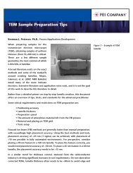
Figure 36: Secondary <strong>ion</strong> image of an uncoated<br />
pollen grain tilted 45°. The cross-sect<strong>ion</strong><br />
itself was made with the same <strong>beam</strong>, but at<br />
a higher <strong>beam</strong> current.<br />
Nano<strong>technology</strong>: the shape of things<br />
to come<br />
The commercializat<strong>ion</strong> of nano-science is limited by the<br />
available tools – the use of a focused <strong>ion</strong> <strong>beam</strong> system<br />
delivers site specific imaging <strong>and</strong> fabricat<strong>ion</strong> <strong>capabilities</strong><br />
that strongly reduce the development <strong>and</strong> characterizat<strong>ion</strong><br />
cycles dem<strong>and</strong>ed by scientists in nano-<strong>technology</strong>.<br />
FIB <strong>capabilities</strong> are highly valuable for rapid prototyping.<br />
As a consequence products <strong>and</strong> profits are brought<br />
more rapidly to the nano<strong>technology</strong> industry.<br />
Nano-particles as catalysts <strong>and</strong> active media in<br />
fuel cells<br />
If there is a need to find out what an active material is<br />
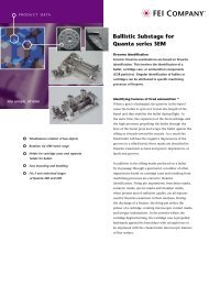
Figure 39: Ion <strong>beam</strong> deposited tungsten<br />
nano-wires for direct electrical measurements<br />
(4 point probe) of nano structures, in this<br />
case a carbon nanotube.<br />
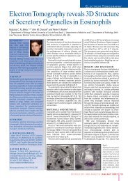
Figure 37: Bright field TEM image showing<br />
the locat<strong>ion</strong> of the platinum group material<br />
deposit at the vertical interface. Locat<strong>ion</strong><br />
proven by EELS mapping (insert showing<br />
the Pt posit<strong>ion</strong> in blue).<br />
Figure 40: SEM image of a FIB machined<br />
single electron nano-bridge in a super-conducting<br />
film. The FIB can even be configured<br />
for dynamic electrical measurements at liquid<br />
helium temperatures during FIB milling.<br />
Figure 38: Customized SNOM tip made with FIB.<br />
doing at a single point in the support matrix, you can<br />
go straight to it <strong>and</strong> find out. Site-specific TEM sample<br />
preparat<strong>ion</strong> of chemical deposits embedded in porous<br />
ceramic media is now no more difficult than polishing a<br />
sample before examining it. Materials independent, sitespecific<br />
TEM samples can be prepared automatically<br />
from any site identified by any technique.<br />
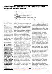
Figure 41 is an EDS map localizat<strong>ion</strong> of a platinum<br />
group material deposit on an internal surface of a ceramic<br />
matrix. The matrix has been injected with a vacuum<br />
proof resin for structural stability. Once the area of interest<br />
is found, the specimen is cut <strong>and</strong> extracted without<br />
breaking the sample. The final step is transfer to a TEM<br />
grid followed by highly detailed (S)TEM analysis.<br />
Figure 41: EDS map showing distribut<strong>ion</strong> of<br />
platinum group deposits within a catalyst<br />
support matrix. The color represents the<br />
relative WT % Pt.<br />
15