MT174 - Technical Description - Iskraemeco UK
MT174 - Technical Description - Iskraemeco UK
MT174 - Technical Description - Iskraemeco UK

You also want an ePaper? Increase the reach of your titles
YUMPU automatically turns print PDFs into web optimized ePapers that Google loves.
<strong>Iskraemeco</strong> <strong>UK</strong> Ltd<br />
1010 Cambourne Business Park<br />
Cambourne<br />
Cambridgeshire<br />
CB23 6DP<br />
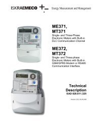
<strong>MT174</strong> Three-phase Electricity Meter<br />
<strong>Technical</strong> Specification<br />
Author:<br />
David Spalding<br />
Revision: 0.2<br />
Release date: 23 October 2012
Copyright Notice<br />
Copyright © 2012<br />
<strong>Iskraemeco</strong> <strong>UK</strong> Ltd<br />
All information in the document is in all cases, except where explicitly stated, the copyright property of<br />
<strong>Iskraemeco</strong> <strong>UK</strong> Ltd, a wholly-owned subsidiary of <strong>Iskraemeco</strong> d.d., 4 Savska Loka, Kranj 4000, Slovenia.<br />
<strong>Iskraemeco</strong> <strong>UK</strong> Ltd reserve any rights not expressly granted herein. Permission to copy or store<br />
electronically, this document or any part of this document or to distribute to third parties is not permitted<br />
without the written consent of <strong>Iskraemeco</strong> <strong>UK</strong> Ltd. Any copy of the document supplied for the purpose of<br />
contract or evaluation must be returned at the end of the contract or evaluation period. This document is<br />
provided under the terms of non-disclosure and ideas, concepts and designs described in this document<br />
may be subject to patent application. Note, the information in this document may be preliminary and<br />
subject to change. This document should not be used as a basis of a contract unless agreed or until<br />
released as a final version.<br />
<strong>Iskraemeco</strong> <strong>UK</strong> Limited Electricity Meter <strong>Technical</strong> Specifications Page | 2
Table of Contents<br />
1.0 Figures 4<br />
2.0 Tables 5<br />
3.0 Foreword 6<br />
3.1 Scope 6<br />
3.2 References 6<br />
4.0 Electricity Meter Requirements 7<br />
4.1 General Platform Features and Capabilities 8<br />
4.2 Measurement Platform 10<br />
4.3 Liquid Crystal Display 11<br />
4.4 Inputs/Outputs 14<br />
4.5 Security 15<br />
4.6 Data Profiling 16<br />
4.7 Billing Management 17<br />
4.8 Clock and Calendar 17<br />
4.9 Tariff Management 18<br />
4.10 Communications 21<br />
4.10.1 Local Optical Interface 21<br />
4.10.2 RS-485 Interface 22<br />
4.11 Serialisation and Markings 22<br />
4.12 Type Designation Code 27<br />
4.13 Faceplate Layout 28<br />
5.0 Requirements Checklist 29<br />
6.0 Document Management 32<br />
7.0 Document Approval 33<br />
<strong>Iskraemeco</strong> <strong>UK</strong> Limited Electricity Meter <strong>Technical</strong> Specifications Page | 3
1.0 Figures<br />
Figure 5-1 Functional architecture 7<br />
Figure 4-2 Terminal cover options 11<br />
Figure 4-3 LCD console layout 12<br />
Figure 4-4 Event status flags 12<br />
Figure 4-5 Current and auxiliary terminal layout 15<br />
Figure 5-13 Season Table example 18<br />
Figure 5-14 Day Profile example 19<br />
Figure 4-8 IEC 62056-21 mode C 21<br />
Figure 4-9 Sample MID meter plate layout 23<br />
Figure 4-10 Faceplate Layout 28<br />
<strong>Iskraemeco</strong> <strong>UK</strong> Limited Electricity Meter <strong>Technical</strong> Specifications Page | 4
2.0 Tables<br />
Table 4-1 Measurement system configuration 10<br />
Table 4-2 Terminal block 11<br />
Table 4-3 LCD display configuration 14<br />
Table 4-4 Auxiliary terminals 14<br />
Table 4-5 Security Management 15<br />
Table 4-6 Load Profile Capacity 16<br />
Table 4-7 Load profile function configuration 16<br />
Table 4-8 Billing profile configuration 17<br />
Table 4-9 Clock management 17<br />
Table 4-10 Tariff management configuration 20<br />
Table 4-11 RS-485 terminal functions 22<br />
Table 4-12 Communications Interfaces 22<br />
Table 4-16 Device identifier configuration 22<br />
Table 4-14 New <strong>UK</strong>MF manufacturer codes 24<br />
Table 4-15 <strong>UK</strong>MF Non-half Hourly MAP codes 25<br />
Table 4-19 Customer serial numbering 25<br />
Table 4-17 Customer logo and barcode 26<br />
Table 4-18 Type designation code 27<br />
Table 5-1 Requirement status 29<br />
Table 5-2 Requirements Summary Table 31<br />
Table 6-1 Document management 32<br />
<strong>Iskraemeco</strong> <strong>UK</strong> Limited Electricity Meter <strong>Technical</strong> Specifications Page | 5
3.0 Foreword<br />
3.1 Scope<br />
The <strong>MT174</strong> is a poly-phase multi-function meter supporting measurement of active, active/reactive or<br />
active/reactive/apparent energy and demand in three-phase four- or three-wire networks. Meter variants<br />
are available for direct connection or indirect connection via current transformers. The meter is approved<br />
for use in single-phase two-wire networks. The <strong>MT174</strong> complies with both European standards EN<br />
50470-1 and EN 50470-3, international standards IEC 62052-11 and IEC 62053-21 and IEC 62052-23.<br />
The meter is designed and manufactured in compliance with ISO 9001 recommendations.<br />
This document details all functional requirements and will be used to derive the final technical<br />
documentation for Production. All aspects of the firmware, hardware, communications and physical<br />
configuration are defined.<br />
Throughout this technical specification, where additional customer clarification is necessary to completely<br />
define a functional requirement without ambiguity, the requirement is clearly marked.<br />
3.2 References<br />
The following documents are referenced throughout this paper:<br />
1. “IEC 62056-21: Electricity metering – Data exchange for meter reading, tariff and load control – Part 21: Direct local data<br />
exchange”, International Electrotechnical Commission, May 2002<br />
2. “IEC 62056-61: Electricity metering – Data exchange for meter reading, tariff and load control – Part 61: OBIS Object<br />
identification system”, International Electrotechnical Commission, November 2006<br />
3. “IEC 62052-11: Electricity metering equipment (AC) - General requirements, tests and test conditions - Part 11: Metering<br />
equipment”, International Electrotechnical Commission, February 2003<br />
4. “IEC 62052-21: Electricity metering equipment (AC) - Particular requirements - Part 21: Static meters for active energy<br />
(classes 1 and 2)”, International Electrotechnical Commission, January 2003<br />
5. “IEC 62052-21: Electricity metering equipment AC) - General requirements, tests and test conditions - Part 21: Tariff and<br />
load control equipment”, International Electrotechnical Commission, April 2005<br />
6. “IEC 62053-23: Electricity metering equipment (AC) - Particular requirements - Part 23: Static meters for reactive energy<br />
(classes 2 and 3)”, International Electrotechnical Commission, January 2003<br />
7. “EN 50470-1:2006: Electricity metering equipment (AC). General requirements, tests and test conditions. Metering<br />
equipment (class indexes A, B and C)”, CENELEC, December 2006<br />
8. “EN 50470-3:2006: Electricity metering equipment (AC) -- Part 3: Particular requirements - Static meters for active energy<br />
(class indexes A, B and C)”, CENELEC, December 2006<br />
9. "<strong>UK</strong> Metering Forum <strong>Technical</strong> Recommendation M1/1 v1.34", <strong>UK</strong> Metering Forum., February 2009<br />
<strong>Iskraemeco</strong> <strong>UK</strong> Limited Electricity Meter <strong>Technical</strong> Specifications Page | 6
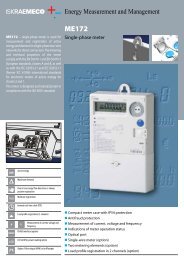
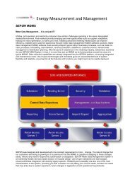
4.0 Electricity Meter Requirements<br />
The <strong>MT174</strong> electronic three-phase meters are designed for measurement and registration of active,<br />
reactive and apparent energy and demand in three-phase four-wire networks. They can be connected<br />
directly to the network. The metering and technical properties of the meters comply with the EN 50470-1<br />
and -3 European standards for active energy meters, classes A and B, as well as with the IEC 62053-21<br />
and IEC 62052-11 international standards for electronic meters of active energy for classes 1 and 2, and<br />
optionally with the IEC 62053-23 international standard for electronic meters of reactive energy for<br />
classes 2 and 3.<br />
Figure 4-1 Functional architecture<br />
A built-in time-switch complies with the IEC 62054-21 and IEC 62052-21 standards. It enables energy<br />
registration in up to four tariffs.<br />
The meter software complies with WELMEC 7.2 Issue 1 Software Guide (Measuring Instruments<br />
Directive 2004/22/EC). The meters are designed and manufactured in compliance with the ISO 9001<br />
(2000) standard.<br />
The <strong>MT174</strong> meters are designed for mechanical environment M1, electromagnetic environment E2 and<br />
climatic environment -40°C to +60°C, relative humidity 95% non-condensing, closed location. The meters<br />
can be installed in any position.<br />
<strong>Iskraemeco</strong> <strong>UK</strong> Limited Electricity Meter <strong>Technical</strong> Specifications Page | 7
4.1 General Platform Features and Capabilities<br />
The <strong>MT174</strong> platform supports the following global functionality and capabilities. The specifics of the<br />
proposed configuration are detailed in successive chapters.<br />
Meter accuracy<br />
· Class A or B in compliance with EN 50470-3 (or 2 or 1 in compliance<br />
with IEC 62053-21) for active energy<br />
· Class 3 or 2 for reactive energy (option)<br />
· Class 3 or 2 for apparent energy (option)<br />
· Meter software in compliance with WELMEC 7.2 Issue 1<br />
Measured quantities<br />
· Energy (active, reactive and apparent)<br />
· Demand (active, reactive and apparent)<br />
· Reactive energy and demand by quadrants<br />
· Instantaneous power<br />
· Phase voltages (UL1, UL2, UL3)<br />
· Phase currents (IL1, IL2, IL3)<br />
· Phase power factors<br />
· Frequency<br />
Modes of energy measurement and registration<br />
· For one-way energy flow direction (import) with an electronic reverse<br />
running stop<br />
· For two energy flow directions (import, export)<br />
· For two-way energy flow direction, with always positive registration, i.e.<br />
energy flowing in the export direction is registered as it flows in import<br />
direction too (only for active energy)<br />
Connection<br />
· Direct whole-current<br />
· Indirect current transformer<br />
Networks<br />
· 3-phase 4-wire<br />
· 3-phase 3-wire<br />
· 1-phase 2-wire<br />
Meter quality<br />
· Due to high accuracy and long term stability of the metering elements<br />
no meter recalibration is required over its lifetime<br />
· Long meter lifetime and high meter reliability<br />
· High immunity to EMC<br />
Real-time Clock<br />
· Accuracy better than ±3 min/year at 23°C<br />
· RTC operation reserve 5 years<br />
· Back-up power supply Li-battery<br />
· Indication of low Li-battery (option)<br />
Time-of-use registration (up to 4 tariffs)<br />
· Tariffs change-over by internal real-time clock<br />
· Optional tariff inputs for external tariff change-over<br />
LCD-display:<br />
· Large LCD in compliance with the VDEW requirements<br />
· IEC 62056-61 OBIS code for data identification<br />
· LCD back-light (option)<br />
Data display modes:<br />
· Automatic cyclic data display (default display time 8 seconds)<br />
· Manual data display mode (by pressing the Scroll push-button)<br />
· Optional data display when the meter is in no-power state<br />
Indicators:<br />
· LCD:<br />
- valid tariff at the moment<br />
- meter status and alarms<br />
- energy flow direction<br />
- phase voltage presence and phase voltage sequence<br />
- reversed energy flow through a particular metering element<br />
· LEDs:<br />
- Imp/kWh<br />
<strong>Iskraemeco</strong> <strong>UK</strong> Limited Electricity Meter <strong>Technical</strong> Specifications Page | 8
- Imp/kvarh (at active and reactive energy meters)<br />
- Imp/kVAh<br />
Powerful load-profile recorder<br />
· Up to 8 channels<br />
· More than 790 days of registration at 1 channel (60min logging period)<br />
Communication channels<br />
· Infrared optical port in compliance with IEC 62056-21 for local<br />
programming and data down-loading<br />
· RS485 serial interface (option)<br />
· Protocol IEC 62056-21 mode C<br />
Pulse outputs<br />
· Class A by IEC 62053-31 (option)<br />
· OptoMOS relay with make contact (option)<br />
Plastic meter case<br />
· Made of high-quality self-extinguishing UV stabilized material that can<br />
be recycled<br />
· Double insulation<br />
· IP54 protection against dust and water penetration (by IEC 60529)<br />
Mechanical environment: M1<br />
Electromagnetic environment: E2<br />
Potential links (whole-current)<br />
· sliding self-braking potential links enable quick disconnection of current<br />
and voltage circuitries<br />
· under terminal block or meter cover<br />
Antifraud functions:<br />
· Detectors (optional)<br />
- meter cover opening<br />
- terminal cover opening<br />
- reversed energy flow direction<br />
- external permanent magnetic field<br />
· Indicators (optional)<br />
- meter cover opening<br />
- terminal cover opening<br />
- reversed energy flow direction trough each of metering<br />
elements<br />
- external permanent magnetic field<br />
Fraud energy registers (optional)<br />
· consumption since the meter cover has been opened<br />
· consumption since the terminal cover has been opened<br />
· consumption since reversed energy flow has been detected<br />
· consumption since external permanent magnetic field has been<br />
detected<br />
Counters of events (optional)<br />
· meter cover opening<br />
· terminal cover opening<br />
· reversed energy flow direction<br />
· external permanent magnetic field<br />
Counters of elapsed time (optional)<br />
· since meter cover has been opened<br />
· since terminal cover has been opened<br />
· since reversed energy flow has been detected<br />
· since external permanent magnetic field has been detected<br />
· total energy registration<br />
· energy registration in a particular tariff<br />
Time-stamps (optional)<br />
· last meter cover opening<br />
· last terminal cover opening<br />
· last reversed energy flow detection<br />
· last external permanent magnetic field tampering<br />
Pushbuttons<br />
· Scroll button<br />
· Billing reset button<br />
<strong>Iskraemeco</strong> <strong>UK</strong> Limited Electricity Meter <strong>Technical</strong> Specifications Page | 9
4.2 Measurement Platform<br />
The measuring system can operate accurately over a wide voltage and temperature range. The current<br />
sensor is a single shunt resistor for single-phase and a system of three Rogowski coils for three-phase.<br />
The voltage sensor is a resistive voltage divider. The continuous analogue signals are converted to<br />
discrete digital pulses and input to the measurement processor for calculation of instantaneous power.<br />
Integrals are calculated, summed and further processed before being written to the relevant data model<br />
register objects.<br />
The basic rating of the meter must be defined which will define the operation limits and overall accuracy.<br />
Additional technical clarification is indicated where required.<br />
Requirement <strong>Description</strong> Value Clarification Notes<br />
MP.01 Number of phases 3 No<br />
MP.02 Coupling method Direct (whole-current) No<br />
MP.03 Nominal voltage (U n ) 230V AC No<br />
MP.04 Voltage range 0.8 U n - 1.15 U n No<br />
MP.05 Reference current (I ref ) 10 A Yes 1<br />
MP.06 Maximum current (I max ) 120 A No<br />
MP.07 Short-circuit current 30 I max No<br />
MP.08 Thermal current 1.2 I max No<br />
MP.09 Nominal frequency 50 Hz No<br />
MP.10 Operating temperature range -40 o C to +60 o C No<br />
MP.11 Extended temperature range -40 o C to +70 o C No<br />
MP.12 Neutral current measurement No No<br />
MP.13 Voltage circuit burden < 0.6W / < 10 VA (without RS-485)<br />
< 0.8W / < 10 VA (with RS-485)<br />
MP.14 Current circuit burden < 0.16 VA No<br />
MP.15 Active accuracy class (MID EN 50470-1) B Yes 2<br />
MP.16 Reactive accuracy class (IEC 62053-21) 2 Yes<br />
MP.17 Apparent accuracy class (IEC 62053-21) 2 No<br />
MP.18 Measurement mode Independent import and export<br />
measurement registers<br />
No<br />
No 3<br />
MP.19 Demand period 30 minutes No 4<br />
Table 4-1 Measurement system configuration<br />
Notes:<br />
1. Clarification of reference (nominal) current rating required for final Production calibration.<br />
2. All meters will be supplied with MID approval for Settlement.<br />
3. Three modes of measurement operation; a) import only measurement, b) independent measurement of<br />
import and export, and c) absolute measurement of import and export (registered in single accumulator).<br />
4. Demand period for current demand, demand in interval, maximum demand and cumulative maximum<br />
demand calculation.<br />
In addition to the basic metrology ratings, metrology constants and terminal covers are required.<br />
However, selection will depend upon input/output configuration requirements, e.g. availability of<br />
inputs/outputs will affect output pulse constant and terminal cover selection.<br />
<strong>Iskraemeco</strong> <strong>UK</strong> Limited Electricity Meter <strong>Technical</strong> Specifications Page | 10
Requirement <strong>Description</strong> Value Clarification Notes<br />
MP.20 Meter/terminal cover removal detection Yes No<br />
MP.21 Terminal cover Extended No 4<br />
MP.22 Active calibration (LED) constant 500 imp/kWh No 5<br />
MP.23 Reactive calibration (LED) constant 500 imp/kvarh No 5<br />
MP.24 Apparent calibration (LED) constant 500 imp/kVAh No<br />
MP.25 Output pulse constant 250 imp/kWh Yes 5<br />
MP.26 Upper mounting hook Yes, plastic Yes 6<br />
Table 4-2 Terminal block<br />
Notes:<br />
5. Two terminal cover variants are available for selection. The short cover exposes I/O terminals but does not<br />
restrict routing of current tails. The extended cover includes break-outs and prevents access to current and<br />
I/O terminals (see Figure 4-2).<br />
6. The LED constants set the ratio between energy consumption and the red front-plate mounted calibration<br />
LED blink rates. The output pulse constant sets the equivalent ration between consumption and impulse<br />
output generation. The output constant is redundant if no physical impulse outputs are available. Output<br />
constant should be half of the meter constant.<br />
7. Additional upper mounting hook options: plastic, short metal or long metal (DIN 43857).<br />
Figure 4-2 Terminal cover options<br />
A connection diagram label including details of network connection, current terminals and I/O terminals is<br />
fixed to the underside of the all terminal covers.<br />
4.3 Liquid Crystal Display<br />
The seven-segment LCD display console is split into five sectors. The data value sector consists of eight<br />
characters each 8mm high. The data identification section displays the five digit OBIS (IEC 62056-61)<br />
identification code of the value currently being displayed in the data value sector in accordance with DIN<br />
43863-3. The OBIS code digits are 5mm in high. A third sector indicates the energy registration<br />
quadrant schematic indicting power flow direction. The fourth sector contains the phase presence/failure<br />
flags (L1, L2 and L3 depending on snigle- or three-phase) and the data value units. Finally, the fifth<br />
sector shows up to eleven additional flags for general meter operation status.<br />
<strong>Iskraemeco</strong> <strong>UK</strong> Limited Electricity Meter <strong>Technical</strong> Specifications Page | 11
Figure 4-3 LCD console layout<br />
The nomenclature and meaning of the meter status flags and OBIS identification codes may be<br />
delineated on the front-plate area reserved for customer definable legends (see section 4.11 Serialisation<br />
and Markings). The status event flag markings layout on the front-plate is shown in Figure 4-4 below (see<br />
<strong>MT174</strong> <strong>Technical</strong> <strong>Description</strong> for details).<br />
T1 T2 T3 T4 MC TC FD REV BAT PD DRO FF SET<br />
X X X X X X X X X X X<br />
Figure 4-4 Event status flags<br />
Requirement <strong>Description</strong> Value Clarification Notes<br />
LCD.01<br />
Energy consumption data<br />
format<br />
7 significant digits + 1 decimal place Yes 6, 7<br />
LCD.02 Demand data format 6 significant digits + 3 decimal places Yes 6, 7<br />
LCD.03 Auto-scroll sequence 1-0:1.7.0<br />
1-0:1.8.0<br />
1-0:2.7.0<br />
1-0:2.8.0<br />
1-0:15.8.0<br />
Instant active import kW<br />
Total active import kWh<br />
Instant active export kW<br />
Total active export kWh<br />
Absolute total active kWh<br />
Yes 8<br />
<strong>Iskraemeco</strong> <strong>UK</strong> Limited Electricity Meter <strong>Technical</strong> Specifications Page | 12
LCD.04 Manual-scroll sequence 0-0:C.1.0<br />
0-0:0.2.0<br />
0-0:C.1.6<br />
0-0:0.9.1<br />
0-0:0.9.2<br />
1-0:1.8.0<br />
1-0:1.8.1<br />
1-0:1.8.2<br />
1-0:2.8.0<br />
1-0:31.7.0<br />
1-0:51.7.0<br />
1-0:71.7.0<br />
1-0:32.7.0<br />
1-0:52.7.0<br />
1-0:72.7.0<br />
1-0:31.6.0<br />
1-0:51.6.0<br />
1-0:71.6.0<br />
1-0:1.7.0<br />
1-0:1.8.0<br />
1-0:2.7.0<br />
1-0:2.8.0<br />
1-0:15.8.0<br />
F.F.0<br />
-<br />
LCD.05 Data readout (DRO) sequence 0-0:C.1.0<br />
0-0:0.2.0<br />
0-0:C.1.6<br />
0-0:0.9.1<br />
0-0:0.9.2<br />
0-0:C.51.1<br />
0-0:C.51.2<br />
0-0:C.51.2*x<br />
0-0:C.51.3<br />
0-0:C.51.4<br />
0-0:C.51.4*x<br />
0-0:C.51.5<br />
0-0:C.51.6<br />
0-0:C.51.6*x<br />
1-0:5.8.0<br />
1-0:6.8.0<br />
1-0:7.8.0<br />
1-0:8.8.0<br />
1-0:9.8.0<br />
1-0:1.8.0<br />
1-0:1.8.1<br />
1-0:1.8.2<br />
1-0:2.8.0<br />
1-0:31.7.0<br />
1-0:51.7.0<br />
1-0:71.7.0<br />
1-0:32.7.0<br />
1-0:52.7.0<br />
1-0:72.7.0<br />
1-0:31.6.0<br />
1-0:51.6.0<br />
1-0:71.6.0<br />
1-0:1.7.0<br />
1-0:1.8.0<br />
1-0:2.7.0<br />
1-0:2.8.0<br />
1-0:15.8.0<br />
F.F.0<br />
Device ID<br />
Firmware version<br />
Firmware checksum<br />
Time<br />
Date<br />
Total active import kWh<br />
Rate 1 active import kWh<br />
Rate 2 active import kWh<br />
Total active export kWh<br />
Instantaneous current L1<br />
Instantaneous current L2<br />
Instantaneous current L3<br />
Instantaneous voltage L1<br />
Instantaneous voltage L2<br />
Instantaneous voltage L3<br />
Instantaneous current L1<br />
Instantaneous current L2<br />
Instantaneous current L3<br />
Instant active import kW<br />
Total active import kWh<br />
Instant active export kW<br />
Total active export kWh<br />
Absolute total active kWh<br />
Fatal error<br />
Display test<br />
Device ID<br />
Firmware version<br />
Firmware checksum<br />
Time<br />
Date<br />
Terminal cover access count<br />
Time of terminal cover access<br />
Timestamps of terminal access<br />
Meter cover access count<br />
Time of meter cover access<br />
Times of meter cover access<br />
Magnetic field detection count<br />
Magnetic field detection time<br />
Magnetic field detection times<br />
Ind. react. import total (R1) kvarh<br />
Cap. react.import total (R2) kvarh<br />
Ind. react. export total (R3) kvarh<br />
Cap. react. export total (R4) kvarh<br />
Apparent import total kVAh<br />
Total active import kWh<br />
Rate 1 active import kWh<br />
Rate 2 active import kWh<br />
Total active export kWh<br />
Instantaneous current L1<br />
Instantaneous current L2<br />
Instantaneous current L3<br />
Instantaneous voltage L1<br />
Instantaneous voltage L2<br />
Instantaneous voltage L3<br />
Instantaneous current L1<br />
Instantaneous current L2<br />
Instantaneous current L3<br />
Instant active import kW<br />
Total active import kWh<br />
Instant active export kW<br />
Total active export kWh<br />
Absolute total active kWh<br />
Fatal error<br />
Yes 9<br />
Yes 10<br />
<strong>Iskraemeco</strong> <strong>UK</strong> Limited Electricity Meter <strong>Technical</strong> Specifications Page | 13
LCD.06 Event flags T1 - T4<br />
MC<br />
TC<br />
FD<br />
BAT<br />
DRO<br />
FF<br />
SET<br />
Current tariff rate<br />
Meter cover open<br />
Terminal cover open<br />
Permanent magnetic influence<br />
Low battery<br />
Data read-out active<br />
Fatal error<br />
Parameter setting access<br />
LCD.07 Backlight No No<br />
LCD.08 No-power reading No No<br />
LCD.09 Reset button Yes No<br />
LCD.10 Test mode at start up No No<br />
LCD.11 Test mode accuracy 8 significant digits + 1 decimal place No<br />
Yes 11<br />
Table 4-3 LCD display configuration<br />
Notes:<br />
8. The proposed maximum displayable consumption value is 999999.9 kWh or kvarh and the maximum<br />
demand value 999.99 kW or kvar.<br />
9. Units displayed will be kW, kvar, kWh or kvarh depending on current data value being displayed.<br />
10. The auto-scroll object list defines the cyclic sequence of data objects that is displayed on the LCD during<br />
normal idle operation. A maximum of 30 registers can be displayed in the sequence. The sequence<br />
updates every 8 seconds by default. The end of the sequence is marked by END (optional).<br />
11. The manual-scroll object list defines the cyclic sequence of data objects displayed when the Standard Data<br />
manual console mode is entered via the blue front panel scroll button (see <strong>MT174</strong> <strong>Technical</strong> <strong>Description</strong> for<br />
details of blue/orange button menu system). A maximum of 50 registers can be displayed in the sequence.<br />
12. The DRO object list defines the predefined list of objects that may be read during communication using IEC<br />
62056-21 mode C (local or remote) or D (local only). A maximum of 120 registers can be displayed in the<br />
sequence.<br />
13. Any of the indicated event flags can be omitted from the LCD display and front-plate legends if required.<br />
4.4 Inputs/Outputs<br />
The meter can be equipped with a selection of auxiliary input and output terminals for tariff rate control,<br />
external measurement logging and communications. The following auxiliary terminals are available:<br />
Tariff inputs (2)<br />
Tariff outputs or impulse outputs (2)<br />
Serial communication channel (RS-485)<br />
Auxiliary terminals are located to the far right of the current terminals in the terminal block. See<br />
X X X X<br />
1 2 3 4 5 6 7 8 9 10 11 12<br />
41 27<br />
40 29<br />
42<br />
Inputs and outputs<br />
Communication port<br />
Figure 4-5 below for a schematic layout.<br />
40 (GND), 41, 42 Impulse outputs<br />
60 (GND), 61, 62 Tariff outputs<br />
15 (GND), 13, 33 Tariff inputs<br />
Requirement <strong>Description</strong> Value Clarification Notes<br />
IO.01 Tariff inputs No No 1<br />
IO.02 Impulse outputs 2 Yes 2<br />
IO.03 Impulse output width 80 ms Yes 3<br />
IO.04 Tariff outputs No No 4<br />
<strong>Iskraemeco</strong> <strong>UK</strong> Limited Electricity Meter <strong>Technical</strong> Specifications Page | 14
IO.05 RS-485 communication port Yes Yes<br />
IO.06 Potential Links Terminal block No<br />
IO.07 Meter terminal cover Long Yes 5<br />
Table 4-4 Auxiliary terminals<br />
Notes:<br />
1. Line to neutral voltage control of active tariff rate. Tariff inputs combine to control rate 1 to 4 activation.<br />
Tariff input 2 may be omitted if not required (2-rate tariff only).<br />
2. Pulse outputs are not available if tariff outputs are selected. Pulse outputs can be line voltage optoMOS<br />
relays (rated 25W, 100mA @ 250V) or opto-isolated open-collector low voltage outputs according to IEC<br />
62053-31 (S0). IEC 62053-31 pulses can be transmitted 0.5 metres and optoMOS relays can be transmitted<br />
up to 1km (depending on cabling).<br />
3. Pulse width may be 10 to 100 ms in 10 ms increments. Relay pulse outputs should typically use longer<br />
pulse durations and lower pulse constants.<br />
4. Tariff inputs are not available if tariff outputs are selected.<br />
5. Meter cover options are short, long and long with internal current terminal fence.<br />
X X X X<br />
1 2 3 4 5 6 7 8 9 10 11 12<br />
41 27<br />
40 29<br />
42<br />
Inputs and outputs<br />
Communication port<br />
40 (GND), 41, 42 Impulse outputs<br />
60 (GND), 61, 62 Tariff outputs<br />
15 (GND), 13, 33 Tariff inputs<br />
Figure 4-5 Current and auxiliary terminal layout<br />
4.5 Security<br />
Security management features include multi-level password authentication and physical tamper detection.<br />
Unauthorised access is protected by three passwords:<br />
· read access to meter data<br />
· write access to meter parameters<br />
· modification of time and date<br />
Passwords can be a maximum of 12 characters in length. Repeat password attack is protected by<br />
temporary local communication channel disablement on incorrect entry of a password three times. An<br />
appropriate entry is also entered in the meter log book, the incorrect password entry counter incremented<br />
and the incorrect password entry timestamp updated.<br />
Requirement <strong>Description</strong> Value Clarification Notes<br />
SM.01 Authentication password 1 READ Yes<br />
SM.02 Authentication password 2 PARAM Yes<br />
SM.03 Authentication password 3 SET Yes<br />
SM.04 Meter cover tamper switch Yes No<br />
SM.05 Terminal cover tamper switch Yes No<br />
SM.06 External magnetic field detection Yes No<br />
SM.07 Reverse flow No No<br />
<strong>Iskraemeco</strong> <strong>UK</strong> Limited Electricity Meter <strong>Technical</strong> Specifications Page | 15
Table 4-5 Security Management<br />
Physical fraud protection includes optional meter cover and terminal cover micro-switches which will<br />
generate log book events, counter increments and timestamps. An optional external magnetic field<br />
influence detector can be fitted and energy consumption during the tamper state can be registered into a<br />
dedicated register.<br />
Lastly, a set of registers monitor the elapsed time since the start of particular event. Monitored events<br />
include:<br />
· duration of meter energisation<br />
· measurement in a particular tariff<br />
· start of magnetic field influence<br />
· start of reverse flow<br />
· duration without voltage (power down)<br />
4.6 Data Profiling<br />
The load profile recorder supports a maximum of eight measurement channels. Energy or demand can<br />
be registered and recorded in each load profile channel. Interval data is marked with a time stamp (date<br />
and time of the end of a logging interval), a meter status field for the interval and a check sum.<br />
Number of<br />
channels<br />
Load Profile Capacity (days)<br />
60 min 30 min 15 min<br />
1 793 396 198<br />
2 476 238 149<br />
3 340 170 85<br />
4 261 130 65<br />
5 214 107 53<br />
6 182 91 46<br />
7 158 79 40<br />
8 140 70 35<br />
Table 4-6 Load Profile Capacity<br />
The capacity of the load profile recorder depends on the logging interval and the number of registered<br />
capture objects (channels) as shown in Table 4-6. If maximum demand is to be measured, the load<br />
profile capture interval and demand period should be of the same value.<br />
Requirement <strong>Description</strong> Value Clarification Notes<br />
DP.01 Load profile capture interval 30 minutes No 1<br />
DP.02 Number of load profile channels 2 Yes<br />
DP.03 Measurement registration Energy Yes 2<br />
DP.04 Channel registered measurement A+<br />
A-<br />
IAI<br />
R+<br />
R-<br />
R1<br />
R2<br />
R3<br />
R4<br />
S<br />
Total import active kWh or kW<br />
Total export active kWh or kW<br />
Absolute active kWh or kW<br />
Total import reactive kvarh or kvar<br />
Total export reactive kvarh or kvar<br />
Reactive kvarh or kvar in 1 st quadrant<br />
Reactive kvarh or kvar in 2 nd quadrant<br />
Reactive kvarh or kvar in 3 rd quadrant<br />
Reactive kvarh or kvar in 4 th quadrant<br />
Total import apparent kVAh<br />
Yes<br />
Yes<br />
-<br />
-<br />
-<br />
-<br />
-<br />
-<br />
-<br />
-<br />
3<br />
<strong>Iskraemeco</strong> <strong>UK</strong> Limited Electricity Meter <strong>Technical</strong> Specifications Page | 16
Table 4-7 Load profile function configuration<br />
Notes:<br />
1. Modifications to a load profile channel capture interval will cause load profile storage to be cleared<br />
permanently. The capture interval can be to 5, 15, 30 or 60 minutes.<br />
2. The load profile recorder can log either energy or demand measurement data.<br />
3. Measurement registration data according to DP.02 number of channels and DP.03 measurement<br />
registration.<br />
4.7 Billing Management<br />
The billing management functionality supports scheduled or manual capture of billing data (consumption<br />
and demand) to historical billing registers. Billing reset events also clear the current maximum demand<br />
for the current billing period. Scheduled capture is performed according to the defined billing period (e.g.<br />
a calendar month) and manual capture is performed via the orange front panel button. A maximum of 15<br />
billing period records can be stored in first in, first out basis. Up to 9 historical billing periods can be<br />
displayed on the LCD.<br />
Scheduled billing resets can be performed either:<br />
· once a year on a specified date and time<br />
· every month on specified day in the month and time<br />
· every month on a specified day in the week with a specified day in the month offset<br />
· every week on a specified day in the week and time, or<br />
· every day<br />
Manual billing resets are activated by pressing the orange Billing Reset button or locally/remotely via one<br />
of the serial interfaces. Billing resets are aligned to the end of the current demand period, i.e. 30 minutes.<br />
Requirement <strong>Description</strong> Value Clarification Notes<br />
BM.01 Number of billing periods (via LCD) 9 No 1<br />
BM.02 Number of billing periods (via serial port) 15 No 1<br />
BM.03 Billing reset blockade period 60 minutes No 2<br />
BM.04 Billing period schedule Monthly on 1st @ 00:00hrs Yes 3<br />
Table 4-8 Billing profile configuration<br />
Notes:<br />
1. The maximum number of billing periods accessible via either the serial communications channels or the<br />
local optical port.<br />
2. Blockade period prevents further billing resets after initial reset.<br />
3. Permitted relative billing periods can be daily, weekly, monthly or yearly. Any time of the day can be set but<br />
the reset will be aligned to the end of the current demand period.<br />
4.8 Clock and Calendar<br />
The real-time clock function supports Daylight Saving Time and configurable time-zone. The clock<br />
function drives all scheduled activity in the meter including profiling and tariff management. The clock is<br />
maintained during power outages by either a built-in lithium battery or super capacitor. A battery offers<br />
backup for 5 years during operation and a 20 year shelf-life, but cannot be exchanged on-site. A supercapacitor<br />
provides backup for short periods (up to 7 days depending on charge), but does not have a<br />
defined lifetime.<br />
Requirement <strong>Description</strong> Value Clarification Notes<br />
CM.01 Time-zone GMT + 0 hrs No 1<br />
CM.02 Daylight Saving Time enabled No Yes 2<br />
<strong>Iskraemeco</strong> <strong>UK</strong> Limited Electricity Meter <strong>Technical</strong> Specifications Page | 17
CM.03 DST start time 01:00hrs last Sunday in March No<br />
CM.04 DST end time 02:00hrs last Sunday in March No<br />
CM.05 RTC backup Lithium battery No<br />
Table 4-9 Clock management<br />
Notes:<br />
1. The time-zone should be fixed to GMT + 0hrs for the <strong>UK</strong>.<br />
2. All calendar functions will operate in GMT mode if DST is disabled.<br />
4.9 Tariff Management<br />
The primary purpose of the tariff management function is to manage the times at which different tariff<br />
rates are active. When a particular rate is active registered energy consumption and demand will<br />
advance in the appropriate measurement register objects.<br />
The heart of the tariff management is the calendar function which holds a hierarchically organised<br />
structure of season, week and day profiles. In terms of the <strong>UK</strong>'s regulated Market Domain Data, the tariff<br />
calendar structure models a Standard Settlement Configuration (SSC) scheme. The tariff programme can<br />
accommodate complex Time-of-Use tariffs:<br />
· 10 seasons per year (weekly tariff programs)<br />
· 10 daily profile definitions<br />
· 10 switching times per daily profile definition<br />
· 46 holidays (exceptional tariff program definition)<br />
The tariff programme calendar consists of two schemes, one active and one passive. The passive<br />
calendar scheme can be used in one of two ways. Firstly, the passive scheme can be used to model a<br />
separate tariff scheme for demand, i.e. separate tariffs for energy and demand whereby energy and<br />
demand registers are switched independently. Secondly, the active scheme switches both energy<br />
consumption and demand registers and the passive scheme holds a standby tariff scheme to be activated<br />
at a future date. This mechanism allows for efficient distribution of new tariff schemes to take affect at a<br />
particular time and date to groups of meters.<br />
Alternatively, tariff rate switching can be prompted by signaling to the optional tariff inputs. In this mode,<br />
both energy and demand registers are switched in the active calendar scheme. Up to four rates can be<br />
switched with both tariff inputs (or two rates with a single tariff input).<br />
The Season Table defines one or more Week Programmes each starting on a particular date in the year.<br />
A Week Programme associates one or more Day Profiles Tables with each day of the week. For<br />
example, a tariff program may run a certain daily switching scheme on weekdays but may revert to a<br />
different daily scheme at the weekend.<br />
Figure 4-6 Season Table example<br />
<strong>Iskraemeco</strong> <strong>UK</strong> Limited Electricity Meter <strong>Technical</strong> Specifications Page | 18
The Day Profile Table consists of a set of scheduled actions (e.g. in <strong>UK</strong> Market Domain Data terms, a<br />
Time Pattern Regime switching time) throughout a 24 hour period from mid-night to mid-night. A<br />
maximum of 10 scheduled times can be defined for each Day Profile. At each scheduled time the<br />
associated script from the Tariff Script Table. Note, an active Day Profile must have a mandatory entry<br />
for 00:00hrs.<br />
Figure 4-7 Day Profile example<br />
The Holiday Table contains entries for holidays and other special days which provide an override of the<br />
regular Day Profile Table for a particular day of the week. For example, an energy supplier may provide<br />
the consumer with a flat weekend rate on Bank Holiday days.<br />
Requirement <strong>Description</strong> Value Clarification Notes<br />
TM.01 Tariff switching mode Internal No 1<br />
TM.02 Passive tariff scheme No Yes 2<br />
TM.03 Passive scheme switch-over n/a Yes 3<br />
TM.04 Tariff programme version identifier - Yes<br />
Active Scheme<br />
TM.05 Active scheme season 1 01 Jan @ 00:00 hrs, week profile 0 Yes 4<br />
TM.06 Active scheme season 2 - Yes 4<br />
TM.07 Active scheme season 3 - Yes 4<br />
TM.08 Active scheme season 4 - Yes 4<br />
TM.09 Active scheme season 5 - Yes 4<br />
TM.10 Active scheme season 6 - Yes 4<br />
TM.11 Active scheme season 7 - Yes 4<br />
TM.12 Active scheme season 8 - Yes 4<br />
TM.13 Active scheme season 9 - Yes 4<br />
TM.14 Active scheme season 10 - Yes 4<br />
TM.15 Active scheme Week Profile 1 Mon - Sun, day profile 0 Yes 5<br />
TM.16 Active scheme Week Profile 2 - Yes 5<br />
TM.17 Active scheme Week Profile 3 - Yes 5<br />
TM.18 Active scheme Week Profile 4 - Yes 5<br />
TM.19 Active scheme Week Profile 5 - Yes 5<br />
TM.20 Active scheme Week Profile 6 - Yes 5<br />
TM.21 Active scheme Week Profile 7 - Yes 5<br />
TM.22 Active scheme Week Profile 8 - Yes 5<br />
TM.23 Active scheme Week Profile 9 - Yes 5<br />
TM.24 Active scheme Week Profile 10 - Yes 5<br />
TM.25 Active scheme Day Profile 1 Rate 1: 00:00hrs Yes 6<br />
<strong>Iskraemeco</strong> <strong>UK</strong> Limited Electricity Meter <strong>Technical</strong> Specifications Page | 19
Requirement <strong>Description</strong> Value Clarification Notes<br />
TM.26 Active scheme Day Profile 2 - Yes 6<br />
TM.27 Active scheme Day Profile 3 - Yes 6<br />
TM.28 Active scheme Day Profile 4 - Yes 6<br />
TM.29 Active scheme Day Profile 5 - Yes 6<br />
TM.30 Active scheme Day Profile 6 - Yes 6<br />
TM.31 Active scheme Day Profile 7 - Yes 6<br />
TM.32 Active scheme Day Profile 8 - Yes 6<br />
TM.33 Active scheme Day Profile 9 - Yes 6<br />
TM.34 Active scheme Day Profile 10 - Yes 6<br />
Passive Scheme<br />
TM.35 Active scheme season 1 - Yes 4<br />
TM.36 Active scheme season 2 - Yes 4<br />
TM.37 Active scheme season 3 - Yes 4<br />
TM.38 Active scheme season 4 - Yes 4<br />
TM.39 Active scheme season 5 - Yes 4<br />
TM.40 Active scheme season 6 - Yes 4<br />
TM.41 Active scheme season 7 - Yes 4<br />
TM.42 Active scheme season 8 - Yes 4<br />
TM.43 Active scheme season 9 - Yes 4<br />
TM.44 Active scheme season 10 - Yes 4<br />
TM.45 Active scheme week profile 1 - Yes 5<br />
TM.46 Active scheme week profile 2 - Yes 5<br />
TM.47 Active scheme week profile 3 - Yes 5<br />
TM.48 Active scheme week profile 4 - Yes 5<br />
TM.49 Active scheme week profile 5 - Yes 5<br />
TM.50 Active scheme week profile 6 - Yes 5<br />
TM.51 Active scheme week profile 7 - Yes 5<br />
TM.52 Active scheme week profile 8 - Yes 5<br />
TM.53 Active scheme week profile 9 - Yes 5<br />
TM.54 Active scheme week profile 10 - Yes 5<br />
TM.55 Active scheme day profile 1 - Yes 6<br />
TM.56 Active scheme day profile 2 - Yes 6<br />
TM.57 Active scheme day profile 3 - Yes 6<br />
TM.58 Active scheme day profile 4 - Yes 6<br />
TM.59 Active scheme day profile 5 - Yes 6<br />
TM.60 Active scheme day profile 6 - Yes 6<br />
TM.61 Active scheme day profile 7 - Yes 6<br />
TM.62 Active scheme day profile 8 - Yes 6<br />
TM.63 Active scheme day profile 9 - Yes 6<br />
TM.64 Active scheme day profile 10 - Yes 6<br />
TM.65 Special day 1 - Yes 7<br />
TM.66 Special day 2 - Yes 7<br />
TM.67 Special day 3 - Yes 7<br />
TM.68 Special day 4 - Yes 7<br />
TM.69 Special day 5 - Yes 7<br />
TM.70 Special day 6 - Yes 7<br />
TM.71 Special day 7 - Yes 7<br />
TM.72 Special day 8 - Yes 7<br />
TM.73 Special day 9 - Yes 7<br />
<strong>Iskraemeco</strong> <strong>UK</strong> Limited Electricity Meter <strong>Technical</strong> Specifications Page | 20
Requirement <strong>Description</strong> Value Clarification Notes<br />
TM.74 Special day 10 - Yes 7<br />
Table 4-10 Tariff management configuration<br />
Notes:<br />
1. The tariff switching mode controls whether rate switching is internal according to the defined Tariff<br />
Programme or externally via the auxiliary tariff inputs. External switching allows the use of an external clock<br />
source or a telemeter with a switched neutral voltage. When external switching is selected Tariff<br />
Programme switching is disabled.<br />
2. The active tariff scheme cannot be modified, however the meter can be supplied with a specified active<br />
scheme and a different passive scheme ready for activation at some time after commissioning or ondemand.<br />
Passive scheme options are none (no passive scheme), inactive (passive scheme with switchover<br />
date and time) or demand (separate tariff programme for demand).<br />
3. Switch-over date and time defines when the passive scheme will be replace the active scheme.<br />
4. The default season is active all year around using week profile 0. Note, season 0 must start on 01 January<br />
at 00:00hrs.<br />
5. By default, Week Profile 1 uses Day Profile 0 every day of the week, Monday to Sunday.<br />
6. By default, Day Profile 1 contains a single entry for 00:00hrs, i.e. rate 1 active all day. Note, an active Day<br />
Profile must have a mandatory entry for 00:00hrs.<br />
7. A maximum of 48 special days (holidays) can be defined. Each special day entry specifies the start date,<br />
recurrence (e.g. every year) and the overriding Day Profile number.<br />
4.10 Communications<br />
The meter includes a local optical interface and an optional RS-485 interface conforming to IEC 62056-21<br />
and IEC 62056-61 public standards [1, 2].<br />
4.10.1 Local Optical Interface<br />
The local optical interface supports IEC 62056-21 mode C for data reading and parameterisation.<br />
Information exchange uses IEC 62056-61 OBIS addressing. The meter will respond to a data readout<br />
request after receiving the appropriate acknowledgement message. The subsequent transmitted<br />
registers are specified by the DRO sequence as defined in Table 4-3 LCD display configuration.<br />
<strong>Iskraemeco</strong> <strong>UK</strong> Limited Electricity Meter <strong>Technical</strong> Specifications Page | 21
Figure 4-8 IEC 62056-21 mode C<br />
The optical interface handshake starts at 300bps regardless of the setting defined in Table 4-12<br />
Communications Interfaces.<br />
4.10.2 RS-485 Interface<br />
The optional RS-485 interface also conforms to IEC 62056-21 and IEC 62056-61 and enables connection<br />
of up to 31 <strong>MT174</strong> meters to a single concentrator, e.g. the P2CC communicator. The network is a<br />
master/slave architecture. The communicator acts as the master and the <strong>MT174</strong> meter is the slave<br />
device.<br />
The maximum distance between the meters and the communicator is 1200 metres. IEC 62056-21 mode<br />
C must be used for data exchange and the data transmission rate is fixed. The default is 9600bps but<br />
may be configured between 300 and 19200bps depending on the master's capability and configuration.<br />
The RS-485 interface is located in the auxiliary terminals on the right side of the terminal block.<br />
Terminal<br />
Path<br />
27 RS-485 A<br />
29 RS-485 A<br />
Table 4-11 RS-485 terminal functions<br />
Note: the meter address may be a maximum of 20 characters, stored in Device Address 1 (register 0.0.0)<br />
and must be unique. If not specified by the client, the default meter address will be the meter serial<br />
number.<br />
Requirement <strong>Description</strong> Value Clarification Notes<br />
OP.01 Device address 1 Yes 1<br />
OP.02 Optical interface baud rate 9600 bps No<br />
<strong>Iskraemeco</strong> <strong>UK</strong> Limited Electricity Meter <strong>Technical</strong> Specifications Page | 22
Requirement <strong>Description</strong> Value Clarification Notes<br />
OP.03 RS-485 baud rate 9600 bps No<br />
Table 4-12 Communications Interfaces<br />
Notes:<br />
1. Customised device serial numbers may be specified for RS-485 slave addressing.<br />
2. Possible values for communications interface baud rate are 300bps,<br />
4.11 Serialisation and Markings<br />
Customisation of the meter front-plate and electronic serialisation can be specified for preparation in<br />
production. The meter supports a number of user definable data objects for storage of supplier specific<br />
serial numbering and other site information, e.g. consumer ID or Standard Settlement Configuration code.<br />
Requirement <strong>Description</strong> Value Clarification Notes<br />
ID.01 Device address 1 Yes 1<br />
ID.02 Device address 2 Null Yes<br />
ID.03 Parameter Scheme ID Null Yes<br />
Table 4-13 Device identifier configuration<br />
Notes:<br />
1. Device address 1 is also the RS-485 slave address and should not be defined if already specified in Table<br />
4-12 Communications Interfaces.<br />
The meter front-plate data and layout is principally dictated by Measuring Instruments Directive (MID)<br />
requirements for electronic meters, however limited customisation of the design is provided for customer<br />
specific information including logos and barcode encoding and formats.<br />
The unique manufacturer serial number (also encoded electronically in Device Address 1 and the Meter<br />
Serial ID registers by default) is used during the production process and for traceability in the event of<br />
customer queries or audit requests. It is recommended to maintain the serial number and barcode (code<br />
39 interleaved 2 of 5) for these purposes.<br />
The user definable area is reserved for customer specific information. The bar code can be encoded with<br />
up to 18 characters of information, e.g. a <strong>UK</strong>MF compliant serial number.<br />
<strong>Iskraemeco</strong> <strong>UK</strong> Limited Electricity Meter <strong>Technical</strong> Specifications Page | 23
Figure 4-9 Sample MID meter plate layout<br />
The current <strong>UK</strong> Metering Forum (administered by Gemserv Ltd) specified supplier serial number format<br />
according to <strong>Technical</strong> Recommendation M-1/1 [9] is due to be replaced by <strong>Technical</strong> Recommendation<br />
M-2 in 01 January 2013 with a format capable of handling the expected annual volumes resulting from<br />
smart metering rollouts. Note, Meter Asset Providers are free to use the new format before this date. A<br />
recent consultation has also been conducted to update the manufacturer identifier codes, however, the<br />
changes do not affect <strong>Iskraemeco</strong>.<br />
The <strong>UK</strong>MF <strong>Technical</strong> Recommendation applies to non-half hourly electricity meters for domestic and<br />
small commercial customers and is intended,<br />
for the guidance of parties responsible for specifying the serial numbers of meters<br />
which they procure<br />
to assist parties in the identification of certain meter characteristics, particularly the<br />
original procurer<br />
The meter serial number format is comprised of the following fields:<br />
A code letter signifying the manufacturer<br />
Two figures to indicate the year of delivery<br />
A code letter or letters signifying the purchasing company (MAP)<br />
An optional gap, a full stop or an additional reference letter or number<br />
A serial number sequence of five digits, beginning with 00001 for each year, each<br />
manufacturer and each purchasing company<br />
A code letter signifying meter use (optional) or an additional serial number digit<br />
<strong>Iskraemeco</strong> <strong>UK</strong> Limited Electricity Meter <strong>Technical</strong> Specifications Page | 24
The allocated manufacturer code letters are indicated in Table 4-14. The letters and numbers must be<br />
indelibly marked therefore have to be stencilled onto the front-plate during production. The sequence of<br />
serial numbers should be allocated by the manufacturer. Manufacturers are permitted to continue to use<br />
their own serial number systems in addition, but this should be placed inconspicuously on interior parts of<br />
the meter.<br />
ID Manufacturer<br />
A<br />
Landis + Gyr<br />
C<br />
CEWE<br />
E<br />
EDMI<br />
F<br />
Siemens Metering Ltd<br />
G -<br />
H<br />
Horstmann Timers and Controls<br />
I<br />
<strong>Iskraemeco</strong> <strong>UK</strong><br />
J<br />
Jinling (Shanghai Electricity)<br />
K<br />
Elster<br />
L<br />
Landis + Gyr<br />
M<br />
General Electric<br />
P<br />
Secure<br />
R<br />
Sagem<br />
S<br />
Itron<br />
Table 4-14 New <strong>UK</strong>MF manufacturer codes<br />
The Meter Asset Provider purchaser codes are show in Table 4-15. Some MAPs have additional codes<br />
which are accommodated by the additional reference letter in the format.<br />
Meter Asset Provider Purchaser code Additional code<br />
Accuread<br />
Z<br />
BGlobal Metering<br />
BM<br />
Central Networks East (now Western Power Distribution) F a - z<br />
Central Networks West (now Western Power Distribution) G a - z<br />
E.ON Energy Services W a - z<br />
EDF Energy CFS<br />
V<br />
EDF Energy Networks (ex Eastern Electricity) E A - Z<br />
EDF Energy Networks (ex London Electricity)<br />
A<br />
EDF Energy Networks (ex SeeBoard)<br />
B<br />
EDF Energy Services<br />
A<br />
IMServ Europe Ltd<br />
U<br />
Independent Power Networks<br />
Lowri Beck Services Ltd<br />
LB<br />
Northern Electric Distribution Ltd<br />
L<br />
Npower Ltd<br />
K<br />
Npower Yorkshire Ltd (Meter Plus)<br />
K<br />
OnStream<br />
X<br />
PRI Ltd<br />
Y<br />
Scottish and Southern Energy (ex Hydro Electric) R a - z<br />
Scottish and Southern Energy (ex Southern Electric) C a - z<br />
Scottish Power Distribution Ltd<br />
P<br />
Scottish Power Manweb<br />
J<br />
Siemens Energy Services S A - Z<br />
Siemens Energy Services T A - Z<br />
United Utilities Networks Ltd N a - z<br />
United Utilities NW (ex Norweb) M a - z<br />
Utility Energy Solutions Ltd<br />
<strong>Iskraemeco</strong> <strong>UK</strong> Limited Electricity Meter <strong>Technical</strong> Specifications Page | 25
Meter Asset Provider Purchaser code Additional code<br />
Utility Partnership Ltd<br />
UP<br />
Western Power Distribution D 0 - 9<br />
Western Power Distribution (South Wales) H 0 - 9<br />
Western Power Distribution (South Wales) H 0 - 9<br />
Western Power Distribution (South West) D 0 - 9<br />
Western Power Distribution (South West) D 0 - 9<br />
Yorkshire Electricity Distribution plc<br />
K<br />
Table 4-15 <strong>UK</strong>MF Non-half Hourly MAP codes<br />
The new format as defined by the forthcoming <strong>Technical</strong> Recommendation M-2 uses the existing Meter<br />
Asset Provider and manufacturer codes with an extended range sequence number, e.g.:<br />
where,<br />
12K1234567<br />
12 is year of manufacture<br />
K is the manufacturer code<br />
1234567 is the sequential serial number<br />
Serial ranges should be defined and specified during production with repeat orders confirming the new<br />
serial sequence range. If a new Meter Asset Provider business is to be purchasing the meters production<br />
will require notification of the new purchaser identifier.<br />
Requirement <strong>Description</strong> Value Clarification Notes<br />
ID.05 Serial sequence range 0000000 - nnnnnnn Yes 1, 2<br />
ID.06 Manufacturer ID I Yes<br />
ID.07 Meter Asset Provider ID Purchaser Additional Yes<br />
- Yes<br />
ID.08 Format 12Innnnnnn Yes Yes 3<br />
Table 4-16 Customer serial numbering<br />
Notes:<br />
1. It is assumed the new serial number format specified by <strong>Technical</strong> Recommendation M-2 will be facilitated<br />
for all production in 2012.<br />
2. One of the user definable Device ID interface class objects may be used to electronically encode a <strong>UK</strong>MF<br />
compliant serial number for access over the WAN interface.<br />
3. The serial format for production of meters in 2012.<br />
Requirement <strong>Description</strong> Value Clarification Notes<br />
ID.09 Customer logo No Yes 1<br />
ID.10 Customer defined text - Yes 2<br />
ID.11 Customer defined serial number No Yes 3<br />
ID.12 Customer defined bar code No Yes 3, 4<br />
ID.13 Customer defined bar code content - Yes 4<br />
ID.14 Customer defined bar code encoding Code 39, interleaved 2 of 5 Yes 4<br />
ID.15 LCD legend (register identification) Yes Yes 5<br />
Table 4-17 Customer logo and barcode<br />
Notes:<br />
<strong>Iskraemeco</strong> <strong>UK</strong> Limited Electricity Meter <strong>Technical</strong> Specifications Page | 26
1. A customer logo should be supplied as a high contrast EPS, JPG, TIFF or GIF file of at least 150dpi at time<br />
of order, if possible. The logo will be scaled to accommodate any additional text and/or serial number.<br />
2. A short customer defined line of text may be specified (
4.12 Type Designation Code<br />
The meter type designation code is stencilled on the front-plate and identifies the major hardware and<br />
software features.<br />
<strong>MT174</strong>-D2A42R56S52-L21-M3K03Z<br />
MT<br />
Three-phase three-system electronic meter<br />
174 With maximum demand and RTC<br />
- -<br />
D1 Terminal block: Imax=85A (DIN 43857)<br />
D2 Terminal block: Imax=120A (DIN 43857)<br />
D3 Terminal block: Imax=100A (BS 5685)<br />
T1<br />
Terminal block up to 6 A<br />
A4 Active energy measurement, accuracy class 1<br />
A5 Active energy measurement, accuracy class 2<br />
1 Energy measurement in one direction<br />
2 Energy measurement in two directions<br />
4 Absolute measurement ΙAΙ<br />
R5 Reactive energy measurement, accuracy class 2<br />
R6 Reactive energy measurement, accuracy class 3<br />
1 Energy measurement in one direction<br />
2 Energy measurement in two directions<br />
4 Absolute measurement ΙRΙ<br />
6 Reactive energy in four quadrants (Q1, Q2, Q3, Q4, +Q, -Q)<br />
- -<br />
S52 Apparent energy, accuracy class 2<br />
-<br />
V<br />
Low voltage passive input<br />
2 Number of inputs<br />
2 Control voltage is 24V DC<br />
G<br />
Low voltage output<br />
n<br />
Number of outputs<br />
2 Transistor output<br />
L<br />
High voltage output (zero volt)<br />
2 Number of relay pulse outputs<br />
1 Pulse output (make contact)<br />
- -<br />
M<br />
Internal clock<br />
2 Back-up power supply (super capacitor)<br />
3 Back-up power supply (lithium battery)<br />
K Communication interface<br />
0 Optical interface (IEC62056-21)<br />
3 RS485 communication interface<br />
Z Load profile<br />
Table 4-18 Type designation code<br />
<strong>Iskraemeco</strong> <strong>UK</strong> Limited Electricity Meter <strong>Technical</strong> Specifications Page | 28
4.13 Faceplate Layout<br />
The layout according to MID requirements as shown in Figure 4-10 shall be adopted for all Settlement<br />
meters.<br />
Figure 4-10 Faceplate Layout<br />
<strong>Iskraemeco</strong> <strong>UK</strong> Limited Electricity Meter <strong>Technical</strong> Specifications Page | 29
5.0 Requirements Checklist<br />
Key<br />
No colour<br />
Green<br />
Orange<br />
<strong>Description</strong><br />
Requirement clear, no further clarification necessary<br />
Further explanation or clarity required<br />
Requirement modified<br />
Table 5-1 Requirement status<br />
The following key is used to track changes to requirements between document releases. Requirement<br />
status is classed as:<br />
i. accepted and requiring no further explanation<br />
ii. requiring further clarification or explanation<br />
iii. confirmed with/without content modification<br />
Confirmation of all technical functional requirements is mandatory to permit the necessary technical<br />
documentation to be prepared for production.<br />
Requirement <strong>Description</strong> Clarification<br />
Measurement Platform<br />
MP.01 Number of phases No<br />
MP.02 Coupling method No<br />
MP.03 Nominal voltage (U n ) No<br />
MP.04 Voltage range No<br />
MP.05 Reference current (I ref ) Yes<br />
MP.06 Maximum current (I max ) No<br />
MP.07 Short-circuit current No<br />
MP.08 Thermal current No<br />
MP.09 Nominal frequency No<br />
MP.10 Operating temperature range No<br />
MP.11 Extended temperature range No<br />
MP.12 Neutral current measurement No<br />
MP.13 Voltage circuit burden No<br />
MP.14 Current circuit burden No<br />
MP.15 Active accuracy class (MID EN 50470-1) Yes<br />
MP.15 Reactive accuracy class (IEC 62053-21) Yes<br />
MP.16 Apparent accuracy class (IEC 62053-21) No<br />
MP.17 Measurement mode No<br />
MP.18 Demand period No<br />
MP.19 Number of phases No<br />
MP.20 Coupling method No<br />
MP.21 Nominal voltage (U n ) No<br />
MP.22 Voltage range No<br />
MP.23 Reference current (I ref ) No<br />
MP.24 Maximum current (I max ) No<br />
MP.25 Short-circuit current Yes<br />
MP.26 Thermal current Yes<br />
Display Console<br />
LCD.01 Energy consumption data format Yes<br />
LCD.02 Demand data format Yes<br />
LCD.03 Auto-scroll sequence Yes<br />
<strong>Iskraemeco</strong> <strong>UK</strong> Limited Electricity Meter <strong>Technical</strong> Specifications Page | 30
Requirement <strong>Description</strong> Clarification<br />
LCD.04 Manual-scroll sequence Yes<br />
LCD.05 Data readout (DRO) sequence Yes<br />
LCD.06 Event flags Yes<br />
LCD.07 Backlight No<br />
LCD.08 No-power reading No<br />
LCD.09 Reset button No<br />
LCD.10 Test mode at start up No<br />
LCD.11 Test mode accuracy No<br />
Inputs and Outputs<br />
IO.01 Tariff inputs No<br />
IO.02 Impulse outputs Yes<br />
IO.03 Impulse output width Yes<br />
IO.04 Tariff outputs No<br />
IO.05 RS-485 communication port Yes<br />
IO.06 Potential Links No<br />
IO.07 Meter terminal cover Yes<br />
Security Management<br />
SM.01 Authentication password 1 Yes<br />
SM.02 Authentication password 2 Yes<br />
SM.03 Authentication password 3 Yes<br />
SM.04 Meter cover tamper switch No<br />
SM.05 Terminal cover tamper switch No<br />
SM.06 External magnetic field detection No<br />
SM.07 Reverse flow No<br />
Data Profiling<br />
DP.01 Load profile capture interval No<br />
DP.02 Number of load profile channels Yes<br />
DP.03 Measurement registration Yes<br />
DP.04 Channel registered measurement Yes<br />
Billing Management<br />
BM.01 Number of billing periods (via LCD) No<br />
BM.02 Number of billing periods (via serial port) No<br />
BM.03 Billing reset blockade period No<br />
BM.04 Billing period schedule Yes<br />
Clock<br />
CM.01 Time-zone No<br />
CM.02 Daylight Saving Time enabled Yes<br />
CM.03 DST start time No<br />
CM.04 DST end time No<br />
CM.05 RTC backup No<br />
Tariff Management<br />
TM.01 Tariff switching mode No<br />
TM.02 Passive tariff scheme Yes<br />
TM.03 Passive scheme switch-over Yes<br />
TM.04 Tariff programme version identifier Yes<br />
TM.05 – 34 Active tariff scheme Yes<br />
TM.35 – 64 Passive tariff scheme Yes<br />
TM.65 – 74 Special days Yes<br />
Local Optical interface<br />
OP.01 Device address 1 Yes<br />
OP.02 Optical interface baud rate No<br />
OP.03 RS-485 baud rate No<br />
Serialisation and Identification<br />
ID.01 Device address 1 Yes<br />
ID.02 Device address 2 Yes<br />
<strong>Iskraemeco</strong> <strong>UK</strong> Limited Electricity Meter <strong>Technical</strong> Specifications Page | 31
Requirement <strong>Description</strong> Clarification<br />
ID.03 Parameter Scheme ID Yes<br />
Table 5-2 Requirements Summary Table<br />
<strong>Iskraemeco</strong> <strong>UK</strong> Limited Electricity Meter <strong>Technical</strong> Specifications Page | 32
6.0 Document Management<br />
Modifications to the document content are described below in Table 6-1 and approved revisions<br />
documented in the Section 7.0 Document Approval.<br />
Version Comment Author Date<br />
0.1 draft Draft release for review David Spalding 05 Oct 2012<br />
0.2 Removed misleading reference to available voltage ranges David Spalding 23 Oct 2012<br />
Table 6-1 Document management<br />
<strong>Iskraemeco</strong> <strong>UK</strong> Limited Electricity Meter <strong>Technical</strong> Specifications Page | 33
7.0 Document Approval<br />
Client approval is required to approve the technical specifications before production technical<br />
documentation can be generated. It is imperative the requirements captured within this document are<br />
accurate to ensure the production of equipment fit for purpose and meeting the Client's expectations.<br />
For Client Use:<br />
Revision Name Role Signature Date<br />
Client comments:<br />
For <strong>Iskraemeco</strong> Use:<br />
Revision Name Role Signature Date<br />
<strong>Iskraemeco</strong> comments:<br />
<strong>Iskraemeco</strong> <strong>UK</strong> Limited Electricity Meter <strong>Technical</strong> Specifications Page | 34