You also want an ePaper? Increase the reach of your titles
YUMPU automatically turns print PDFs into web optimized ePapers that Google loves.
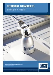
<strong>Designers</strong> Guide<br />
RoofSafe Anchors<br />
Always read and follow the warnings and instructions for use<br />
© Copyright Capital Safety Systems Ltd 2013<br />
THE ULTIMATE IN FALL PROTECTION
RoofSafe Anchor<br />
Contents<br />
1.0 Foreword<br />
2.0 General<br />
2.1 Authorised Installers<br />
2.2 Conformity<br />
2.3 Work Restraint & Fall Arrest<br />
2.4 Free Fall Space Calculator<br />
3.0 Site Assessment<br />
3.1 Reviewing the Task<br />
3.2 Typical System Layout<br />
3.3 Specifying Your Anchor<br />
3.4 Roof Types & Anchors<br />
3.4.1 Wood Deck (Built up)<br />
3.4.2 Metal Deck (Built up / Composite)<br />
3.4.3 Solid Concrete (Built up)<br />
3.4.4 Hollow Concrete (Built up)<br />
3.4.5 Trapezoidal Insulated Panel<br />
3.4.6 Standing Seam<br />
3.5 Sealing Details<br />
3.6 Aggressive & Hazardous Environments<br />
3.7 Rescue Planning<br />
4.0 RoofSafe Anchor<br />
Performance<br />
4.1 Anchorage Strength<br />
4.2 Forces on the SpiraTech Anchor<br />
4.3 Forces on a Tip Over Anchor<br />
4.4 Thermal Bridging<br />
5.0 Annual Maintenance<br />
5.1 Testing the Roof Anchor<br />
5.2 Testing the Swages<br />
5.3 Cleaning the Anchor<br />
6.0 Reference Documents<br />
6.1 Abbreviations and Definitions<br />
6.2 Standards Table<br />
6.3 Markings Explained<br />
6.4 Inspection log.<br />
Issue Date: 10/05/13 Issue No: 2<br />
2
RoofSafe Anchor<br />
1.0 Foreword<br />
1.0 Foreword<br />
It is important that this guide is read and fully understood before the RoofSafe Anchors or RoofSafe Cable system is installed or<br />
serviced. The RoofSafe Anchor has been designed to prevent or minimise the risk of injury from falls. Incorrect design, installation or<br />
servicing through failure to adhere to these instructions could result in serious consequences.<br />
This guide outlines applications for each anchor and each typical roof type that the designer may encounter including recommended fixing<br />
types and methods. It explains the forces on the anchor and the system and how this relates to the forces transferred to the roof structure.<br />
Information on the anchors performance, details of standards to which the anchors conform and testing which has been carried out by<br />
Capital Safety are given for reference to ensure that the correct product is being used for each specific application.<br />
It is important that management ensure that personnel who they direct to install or service the RoofSafe Anchor products are trained to<br />
the standards expected by Capital Safety.<br />
This guide is an essential reference document for designing a RoofSafe Anchor and RoofSafe Cable System.<br />
Issue Date: 10/05/13 Issue No: 2<br />
3
RoofSafe Anchor<br />
2.0 General<br />
2.0 General<br />
2.1 Authorised Installers<br />
Only competent installers certified by Capital Safety are allowed to install and service the RoofSafe Anchor or RoofSafe Cable System.<br />
2.2 Conformity<br />
The RoofSafe Anchor System is a roof top anchorage system which is tested and where appropriate certified in accordance with the<br />
requirements of various national and international standards and codes of practice. Details can be found in standards table, Section 6.2.<br />
Components or parts are not to be altered, modified, dismantled or be replaced with items not supplied or manufactured by Capital Safety,<br />
such action will invalidate any certification and could result in serious or fatal consequences.<br />
Parts or components not supplied by Capital Safety may be of inferior specification and may cause incorrect operation of the system.<br />
2.3 Work Restraint & Fall Arrest<br />
The RoofSafe Anchor is a complete fall protection system. It has been designed to solve problems relating to falls from a height. All<br />
Anchors for all structure’s must be designed for fall arrest, although it is best to restrain the user to prevent a fall occurring.<br />
WORK RESTRAINT<br />
The advantages with work-restraint are that:<br />
• Workers do not have to be subjected to the abrupt impact of an arrest as would be the case in a fall-arrest system, or risk falling into a<br />
hazard e.g. water or a hazardous substance.<br />
• The user can not be injured from swing-fall incidents.<br />
• There is no need for any rescue provision.<br />
• Personnel require less training.<br />
Issue Date: 10/05/13 Issue No: 2<br />
4
RoofSafe Anchor<br />
2.0 General<br />
In a work restraint system, to prevent the worker from entering an area where they could fall, there are two dimensions which need to be<br />
strictly controlled:<br />
• The lanyard length A (Fig 1)<br />
• The distance from the Anchor to the fall hazard B (Fig 1)<br />
A scale drawing should be made to ensure that the lanyard (including connectors) will always prevent the user from entering a fall arrest<br />
situation. If the position of the fall hazard relative to the Anchor varies this analysis should be performed at various points along the length of<br />
the system.<br />
Work Restraint Orientation<br />
Fall Arrest Orientation<br />
A<br />
B<br />
A<br />
B<br />
Fig 1 Fig 2<br />
FALL ARREST<br />
Where a work restraint system cannot be employed, a fall-arrest system has to be used. The disadvantage is that a worker has to fall before<br />
the system can operate (Fig 2) and arrest the fall. This is achieved by applying a braking force to the worker for a few hundredths of a<br />
second. The RoofSafe Anchor and RoofSafe Cable systems ensure that the braking force is always kept below a safe load, providing<br />
that the worker is wearing a full body harness and an energy-absorbing lanyard certified to the appropriate national standard.<br />
When designing the roof safety system, be aware of falls through fragile elemnts as well as falls from exposed edges.<br />
In a fall arrest situation appropriate rescue procedures must be in place to return the worker to safety as soon as possible. Refer to the<br />
Rescue planning section of this guide (Section 3.7).<br />
IMPORTANT NOTE<br />
Whilst all horizontal lifeline systems must be designed for Fall Arrest in case of accidental misuse, it is recommended that system should<br />
be designed for Work Restraint. This design enables a user to access their work area whilst being prevented from being exposed to a fall<br />
hazard. This design will reduce risk and mitigate the consequences of a fall.<br />
Issue Date: 10/05/13 Issue No: 2<br />
5
RoofSafe Anchor<br />
2.0 General<br />
2.4 Free Fall Space Calculator<br />
Capital Safety provides a calculation tool which helps the designer to assess the recommended free space required below the system to<br />
ensure that the system is safe to use. The calculation tool and information on how to use it is available from Capital Safety separately from<br />
this guide.<br />
Below is a picture of the calculation sheet (Fig 3)<br />
Free Fall Space Calculator<br />
RoofSafe Anchors<br />
RoofSafe Cable<br />
Using the input boxes below, change the values to suit the length of your RoofSafe Cable & Anchor system.<br />
Note: Calculations are based on maximum span widths (12m) with the fall occuring in the midspan of the system.<br />
Project Name<br />
Date<br />
Inputs<br />
Title Character Units Values Description<br />
Lanyard Length L m Total length of lanyard<br />
Edge Distance E m Distance from the edge of the roof to the system<br />
Number of Users U # Total number of users per span<br />
D-Ring Height D m Height from roof surface to the user connection point<br />
System Length S m Total length of system (or section of system)<br />
Outputs<br />
Title Character Units Value<br />
Fall potential FP m<br />
Fall factor (fall potential / lanyard length) FF m<br />
Minimum distance required below platform level MD m<br />
Maximum end loads ML kN<br />
Issue No: 01<br />
Issue Date:<br />
05/03/2012<br />
Fig 3<br />
Issue Date: 10/05/13 Issue No: 2<br />
6
RoofSafe Anchor<br />
3.0 Site Assessment<br />
3.0 Site Assessment<br />
3.1 Reviewing the Task<br />
Only installers certified by Capital Safety are allowed to install and service the RoofSafe Anchors and RoofSafe Anchor Cable Systems.<br />
SITE SURVEY<br />
At the start of each job a site survey should be carried out to assess the type and location of the system required. Accurate measurements<br />
should be taken to make sure that the system will fit the required area correctly.<br />
During a site survey the following information should be gathered:<br />
• The purpose of the system / Task to be performed<br />
• The maximum No. of people that will be using the system at any one time.<br />
• The specification and manufacturer of the roof to which the system will be fitted, including critical dimensions such as seam/crown<br />
centres and insulation thickness<br />
• Scale drawings of the structure or building (in digital format if available)<br />
• The exact path of the system<br />
• Any special requirements from the architect or the customer such as; a specific type of bracket, or particular considerations for historical<br />
buildings.<br />
• The risks to the installers so that suitable risk controls during installation can be planned.<br />
When seeking technical support on a specific job, the Capital Safety sales team will be able to help you more quickly if you have the above<br />
information available as a minimum.<br />
METHOD STATEMENTS<br />
Before work begins a method statement should be written by the installer, agreed with the client and signed by both the parties. This is a<br />
detailed step by step guide of how the work is to be carried out by the installer.<br />
The method statement protects both the client and the installer in the event of the work not being carried out in a safe manner, and can be<br />
used to ensure that the workers are adhering to safe and suitable working practices while carrying out the work.<br />
VERIFYING THE ROOF STRUCTURE<br />
The strength of the roof structure should be verified before the system is fitted to ensure that the fixings are strong enough to hold the<br />
anchor onto the roof. This can be done by calculation or through roofing approvals. Contact Capital Safety for any specific roof testing that<br />
may be relevant to the roof profile<br />
Where these methods can not be used to verify the strength of the structure and the fixings, a sample fixing should be installed, and pull<br />
tested. The fixings should withstand as a minimum the forces given in the RoofSafe Anchor Forces Calculation Sheet.<br />
Issue Date: 10/05/13 Issue No: 2<br />
7
RoofSafe Anchor<br />
3.0 Site Assessment<br />
3.2 Typical System Layout<br />
B E E B<br />
KEY:<br />
A - SpiraTech Anchor as<br />
System end post<br />
B - SpiraTech Anchor as Corner<br />
post<br />
C - Tip Over Anchor as<br />
Intermediate post<br />
D - SpiraTech Anchor as<br />
System t-joint, with RA throw<br />
plate<br />
E - SpiraTech Anchor as<br />
Variable post for roof hips<br />
C<br />
A<br />
D<br />
Max 12m<br />
A<br />
E<br />
A<br />
E<br />
Direction of Fall Hazard<br />
Issue Date: 10/05/13 Issue No: 2<br />
8
RoofSafe Anchor<br />
3.0 Site Assessment<br />
GAINING ACCESS TO THE ANCHOR<br />
The entry point is defined as the point where the user can attach to the system. The exit point is defined as the point where the user can<br />
detach from the system. The entry point and the exit point can be at the same position. It is important to remember that the user is not<br />
fully protected from a fall until the safety lanyard and harness are attached and secured to the attachment eye or Unigrab, via a carabiner.<br />
Consideration should always be given to the positioning of the Anchor in regards to the above. The entry point should always be in a safe<br />
area, i.e. free from fall hazards. Where this cannot be achieved, a secondary means of fall protection needs to be installed to give protection<br />
whilst bridging the gap between the access route and the Anchor. The same consideration needs to be made in respect to the exit point,<br />
should it be in a different position to the entry point.<br />
SWING FALLS<br />
Swing falls can be fatal when working near a gable end. Fig 8 shows a worker using a rope and grab at maximum extension near a gable<br />
end. In this case the flank length exceeds the ridge height so if the user falls they have inadequate clearance to ground level. Another<br />
risk is the slicing effect of the edge of the roof on the rope or lanyard as the user falls. This situation must be avoided. Installation of edge<br />
protection to the end elevation and Installing the Anchor inboard of the roof eaves can help to alleviate this issue.<br />
Frank Length<br />
Ridge Height<br />
Fig 8<br />
E<br />
D<br />
C<br />
A<br />
A<br />
B<br />
A) Inaccessible zone<br />
B) Zone for potential<br />
swing fall<br />
C) User<br />
D) Lanyard<br />
E) RoofSafe Anchor<br />
System<br />
E<br />
B<br />
B<br />
D<br />
F<br />
C<br />
A<br />
A) Swing fall zone<br />
B) Accessible area<br />
with anti swing<br />
fall posts<br />
C) User<br />
D) Lanyard<br />
E) RoofSafe<br />
Anchor System<br />
F) Single point<br />
anchor as anti<br />
swing fall post<br />
Fig 9.1 Fig 9.2<br />
Fig 9.1 shows the potential swing fall and the inaccessible areas. Fig 9.2 shows how the swing fall potential can be limited when using a<br />
manually adjustable lanyard and an single point anchor as an anti swing fall post. Further information can be found in BS7883:2005.<br />
Issue Date: 10/05/13 Issue No: 2<br />
9
RoofSafe Anchor<br />
3.0 Site Assessment<br />
3.3 Specifying Your Anchor<br />
The RoofSafe Anchor provides a secure anchor point for a worker at height, close to an exposed edge or other fall hazards, when used in<br />
conjunction with associated PPE, such as a full body harness and a energy absorbing lanyard.<br />
The RoofSafe Anchor is designed to re-orientate and deploy an energy absorber in the event of a fall, thereby reducing the load<br />
transferred to the user and the roofing system. The Anchor can be used for both fall arrest and work restraint applications.<br />
There are two types of Anchors within the range. The SpiraTech Anchor and the Tip Over Anchor. Both anchors are modular in design<br />
allowing for speed of fitting and use.<br />
Both Anchors allow the user to walk 360 degrees around the anchor without needing to reorientate the lanyard or connectors. The Anchor<br />
allows full weather sealing to prevent water ingress, and allows different roof membranes to be fitted and sealed around the anchor for true<br />
weather proofing.<br />
The modular design allows the designer to chose and purchase the baseplate, module and top attachment separately. This gives true<br />
flexibility for application to any roof type or membrane.<br />
+<br />
+<br />
Fig 10.1 Base Plate<br />
Fig 10.2 SpiraTech or Tip<br />
Over Module<br />
Fig 10.3 Attachment Eye<br />
Fig 11.1 Assembled<br />
SpiraTech Anchor<br />
Can be used as a single point anchor for up to<br />
two users<br />
Fig 11.2 Assembled Tip<br />
Over Anchor<br />
Can be used as a single point anchor for one user.<br />
Issue Date: 10/05/13 Issue No: 2<br />
10
RoofSafe Anchor<br />
3.0 Site Assessment<br />
BASE PLATES<br />
The base plate designs incorporate several fixing holes to allow the same plate to be fitted on dissimilar roof types. The base plates also<br />
accommodate common roof pitch centres, allowing the baseplates to be used in two orientations. There are two blank base plate sizes for<br />
roofs that do not have typical centres (not shown).<br />
Fig 12.1 Fig 12.2 Fig 12.3<br />
RA Baseplate 405mm X 405mm<br />
Available with holes or blank<br />
RA Baseplate 350mm X 440mm<br />
Available with holes or blank<br />
RA Baseplate 550mm X 450mm<br />
PITCH MATRIX<br />
Roof Type<br />
Pitches (mm)<br />
Trapezoidal<br />
Standing Seam<br />
Base Plates 200 250 275 300 304 333 334 347 350 367 400 500 200 300 400<br />
x x x x x x x x<br />
RA Base Plate 405x405 Holes<br />
7241136<br />
RA Base Plate 405x405 Blank<br />
7241137<br />
RA Base Plate 350x440 Holes<br />
7241138<br />
RA Base Plate 350x440 Blank<br />
7241139<br />
RA Base Plate 550x450 Blank<br />
7241140<br />
x x x x x x x x x x x x<br />
x x x x<br />
x x x x x x x x x x x x x x<br />
x x x x x x x x x x x x x x x<br />
NOTE: This table assumes the baseplate can only be fitted on the centre of the crown of the<br />
trapezoidal roof sheet, if the fixings do not have to be central to the crowns the plates will fit sizes<br />
other than those stated. Always check with the roof manufacturer for guidance<br />
PITCHES FOR TOGGLE FIXING<br />
The RA Baseplate 405x405 H (7241136) incorporates hole centres for the toggle fixings. The<br />
holes are set at two pitches of 333 and 200. Capital Safety have done extensive research to<br />
ensure that these fixing centres are suitable for as many styles and pitches of roof deck as<br />
possible. If you find that the standard holes are not suitable for a particular roof type, the blank<br />
baseplates can be drilled with the correct hole type in alternative locations. If you have any<br />
queries contact Capital Safety.<br />
Issue Date: 10/05/13 Issue No: 2<br />
11
RoofSafe Anchor<br />
3.0 Site Assessment<br />
3.4 Roof Types and Anchors<br />
Images of anchors in this section are for indicative purposes only<br />
3.4.1 WOOD DECK, (BUILT UP)<br />
Built up roof type with rigid insulation and wooden roof<br />
deck. The deck must be a minimum thickness of 18mm<br />
Fixings:<br />
RoofSafe Anchor Toggle Fix 150mm x 4 (7241182)<br />
RoofSafe Anchor Toggle Fix 300mm x 4 (7241183)<br />
Fig 13.1<br />
3.4.2 METAL DECK, (BUILT UP / COMPOSITE)<br />
Built up or composite panel roof with rigid insulation and<br />
a Trapezoidal metal deck.<br />
Fixings:<br />
RoofSafe Anchor Toggle Fix 150mm x 4 (7241182)<br />
RoofSafe Anchor Toggle Fix 300mm x 4 (7241183)<br />
Fig 13.2<br />
3.4.3 SOLID CONCRETE, (BUILT UP)<br />
Warm solid concrete roof with rigid insulation.<br />
Fixings:<br />
RoofSafe Anchor Concrete Fix 150mm x 4 (7241180)<br />
RoofSafe Anchor Concrete Fix 300mm x 4 (7241181)<br />
Fig 13.3<br />
Issue Date: 10/05/13 Issue No: 2<br />
12
RoofSafe Anchor<br />
3.0 Site Assessment<br />
3.4.4 HOLLOW CONCRETE, (BUILT UP)<br />
Warm hollow concrete roof with rigid insulation.<br />
Fixings:<br />
RoofSafe Anchor Concrete Fix 150mm x 4 (7241180)<br />
RoofSafe Anchor Concrete Fix 300mm x 4 (7241181)<br />
Fig 13.4<br />
3.4.5 TRAPEZOIDAL INSULATED PANEL<br />
Pre-insulated/<br />
Built up metal roof panels.<br />
Fixings:<br />
RoofSafe 7.7 Rivet (7234005)<br />
Fig 13.5<br />
3.4.6 STANDING SEAM<br />
Standing seam roof, Aluminium Steel or Stainless Steel.<br />
Posts can be fitted to a range of seam profiles and roof<br />
sheet materials, see details on page 14.<br />
Fig 13.6<br />
Issue Date: 10/05/13 Issue No: 2<br />
13
RoofSafe Anchor<br />
3.0 Site Assessment<br />
STANDING SEAM ROOFING SYSTEMS<br />
When Specifying a RoofSafe Anchor for a standing seam consideration should first be given to the Standing Seam profile and the type of<br />
clamps that will be required to secure the anchors to the roof<br />
Capital Safety provides a range of fixing clamps to fit to varying roof seam profiles. Details on individual clamp compatibility can be provided<br />
by Technical Services.<br />
Bulb Type Standing Seam<br />
RoofSafe Maxi Clamp Z (7234028)<br />
Folded Seam<br />
RoofSafe Maxi Clamp E (7234008)<br />
Folded Seam<br />
RoofSafe Maxi Clamp U (7234029)<br />
Fig 14<br />
The baseplate selection will be based on the roofing centres, see the matrix on page 11 for more detail.<br />
IMPORTANT NOTE:<br />
It is recommended to avoid fitting clamps directly over halter clips as this will affect the performance of the clamp and the roof. Always refer<br />
to the roofing manufacturer for guidance.<br />
Issue Date: 10/05/13 Issue No: 2<br />
14
RoofSafe Anchor<br />
3.0 Site Assessment<br />
3.5 Sealing Details<br />
B<br />
A<br />
B<br />
A<br />
D<br />
PVC MEMBRANE<br />
A PVC bonded onto the weather<br />
shround up to the ridge<br />
B RA weather shroud PVC<br />
C Baseplate<br />
D Toggle fixing sealed in under the membrane<br />
C<br />
D<br />
BITUMEN MEMBRANE<br />
A Bitumen sealed onto the weather<br />
shround up to the ridge<br />
B RA weather shroud<br />
C Baseplate<br />
D Toggle fixing sealed in under the bitumen<br />
C<br />
RA Module PVC SpiraTech / Tip Over<br />
RA Module BIT SpiraTech / Tip Over<br />
B<br />
A<br />
D<br />
B<br />
C<br />
D<br />
OTHER MEMBRANES<br />
A Membrane sealed over the baseplate<br />
and up to the top of the can<br />
B RA Weather Cap<br />
C Baseplate<br />
D Toggle fixing sealed in under the membrane<br />
E RA Seal Ring<br />
E<br />
C<br />
A<br />
RIVET FIX AND STANDING SEAM<br />
A RA Seal Ring<br />
B RA Can<br />
C Baseplate<br />
D Fixings with Seals or Clamps which<br />
do not penetrate the roof.<br />
RA Module All Mem SpiraTech / Tip Over<br />
RA Module Top Fix SpiraTech / Tip Over<br />
Information in this section is given as a guide only, always refer to the roofing manufacturers information for their specifications.<br />
Issue Date: 10/05/13 Issue No: 2<br />
15
RoofSafe Anchor<br />
3.0 Site Assessment<br />
3.6 Aggressive and Hazardous Environments<br />
CORROSIVE ENVIRONMENTS<br />
The RoofSafe Anchor has been tested in saline environments that exceed those specified in all National Standards. All components that<br />
are continuously exposed to the atmospheric conditions are made from Aluminium or Stainless Steel.<br />
Aluminium components are anodized to AA11 (11 microns thick) as a minimum and 316 stainless steel components are polished to remove<br />
any surface impurities.<br />
The SpiraTech coil and associated steel components are coated in a Zinc inorganic coating which has a minimum saline performance of<br />
1000 Hrs.<br />
In an aggressive or saline environment a RoofSafe Anchor and RoofSafe Cable System will require more frequent inspections and<br />
servicing to assure corrosion damage is not affecting the performance of the product. A appropriate inspection plan should be implemented<br />
based on the environmental conditions and agreed with the customer.<br />
CHEMICAL HAZARDS<br />
Solutions containing acids, alkali, or other caustic chemicals, especially at elevated temperatures may cause damage to this equipment.<br />
Consult Capital Safety if doubts exists concerning installing this equipment where chemical hazards are present.<br />
ELECTRICAL HAZARDS<br />
Do not install the RoofSafe Anchor where either the anchor, cable or user can come into contact with electrical power lines. Always allow<br />
a safe working distance between the user and power lines.<br />
If you are uncertain about a particular application please contact your local energy infrastructure provider or health and safety advisory<br />
service for information on safe working practices.<br />
3.7 Rescue Planning<br />
Employers have a reponsibility to make specific provisions for emergency planning. Work should be appropriately planned and previsions<br />
should be made for emergency situations. The need for rapid and appropriate response following a fall should not be ignored.<br />
In any situation where a fall could occur it is essential that appropriate rescue equipment is available for rapid deployment by trained<br />
personnel. Failure to have correctly trained personnel and equipment in place to respond to a fall scenario may result in serious injury or<br />
death.<br />
Capital Safety has a range of rescue equipment appropriate for different scenarios and can advise on specification and use. Capital Safety<br />
also has facilities to provide training which is essential for the safe and correct use of rescue and evacuation equipment.<br />
Issue Date: 10/05/13 Issue No: 2<br />
16
RoofSafe Anchor<br />
4.0 Roof Anchor Performance<br />
4.0 Roof Anchor Performance<br />
4.1 Anchorage Strength<br />
The anchor has been designed to withstand the loads generated when a person falls from height while attached to the anchor. The range<br />
of Roof Anchors are designed with internal supports which enable the post to maintain correct system tension as well as allowing for annual<br />
testing of the strength of the fixings (section 5.1). The internal supports break away at less than 3kN allowing the energy absorbing element<br />
to take the full force of the fall.<br />
Once the anchor has been deployed the energy absorbing elements reduce the load on the user and the roof to safe levels, so that the<br />
anchorage remains safely attached to the roof structure, and the user is brought comfortably to a post fall resting position.<br />
The RoofSafe Anchor can then withstand a minimum static load of twice the peak arrest load for 3 mins as required by EN795.<br />
4.2 Forces on the SpiraTech Anchor<br />
SCALE<br />
HIGH STRESS<br />
LOW STRESS<br />
Fig 15.1<br />
Fig 15.2<br />
Fig 15.2 shows a horizontal load applied to the anchor connector. The highest stress areas can be seen around the narrowest section of the<br />
pin where it is designed to break.<br />
SCALE<br />
HIGH STRESS<br />
LOW STRESS<br />
Fig 16<br />
Fig 16 shows the coil deployed, it can be seen that the stress is taken up by the middle section of the coil. (The rest of the assembly is not<br />
shown for clarity)<br />
Issue Date: 10/05/13 Issue No: 2<br />
17
RoofSafe Anchor<br />
4.0 Roof Anchor Performance<br />
The SpiraTech Force management technology, absorbs much of the impact energy returning a low peak load as shown in the traces<br />
below Fig 17a/17b.<br />
EN 795 - Dynamic 100kg, 2.5m<br />
ACR - Dynamic 200kg, 1.5m<br />
Force (kN)<br />
Time (secs)<br />
Peak 5,2kN<br />
Equivalent of a single user<br />
fall on a SpiraTech Anchor<br />
Peak 6,1kN<br />
Equivalent of a two user<br />
fall on a SpiraTech Anchor<br />
Fig 17a<br />
Fig 17b<br />
In a system the load is transmitted to the ends and the corners. Therefore ends and corners should be secured by means of a SpiraTech<br />
anchor rather than a Tip Over anchor. Tip Over anchors can be used as intermediate posts as they see less load. A system consisting of 2<br />
SpiraTech anchors (Fig 18) will return a peak load of approximately 4.6kN (Fig 19).<br />
Fig 18<br />
However if a second user was to fall on the system after the anchor had<br />
already been deployed the peak load would increase to approximately<br />
5.7kN (Fig 19)<br />
Force (kN)<br />
Drop On Deployed System<br />
System<br />
Time (secs)<br />
Fig 19<br />
Equivalent of a single user fall on a RoofSafe<br />
Cable system SpiraTech posts<br />
Issue Date: 10/05/13 Issue No: 2<br />
18
RoofSafe Anchor<br />
4.0 Roof Anchor Performance<br />
4.3 Forces Tip Over Anchor<br />
SCALE<br />
HIGH STRESS<br />
LOW STRESS<br />
Fig 20.1<br />
Fig 20.2<br />
Fig 20.2 shows a horizontal load applied to the anchor connector. The highest stress areas can be seen around the top and bottom of the<br />
support strap where it is designed to break.<br />
Fig 21 Shows the deformation of the wire form under a<br />
horizontal load, It can be seen that wire orientates the load<br />
and absorbs energy from the fall.<br />
SCALE<br />
HIGH STRESS<br />
LOW STRESS<br />
Fig 21<br />
The Single Point Anchor absorbs much of the impact<br />
energy returning a peak load of approximately 7.1kN as<br />
shown on the trace in Fig 22.<br />
Fig 22<br />
Issue Date: 10/05/13 Issue No: 2<br />
19
RoofSafe Anchor<br />
4.0 Roof Anchor Performance<br />
4.4 Thermal Bridging<br />
Loss of heat from a building is a concern on insulated built up roof types where the toggle fixings penetrate through the roof (Fig 23.1). This<br />
can create a thermal bridge through the central bolt. The RoofSafe anchor toggles minimise the affect by insulating the area around the<br />
toggle bolt (Fig 23.2). In common toggle fixings the area around the bolt is open allowing convection around the bolt as well as conduction<br />
through the bolt.<br />
Toggle Top<br />
Support tube<br />
Foam Insulation<br />
Bolt<br />
Transfer of heat<br />
Toggle Pressing<br />
Fig 23.1<br />
Uninsulated Toggle Fixing<br />
Fig 24<br />
RoofSafe Anchor Toggle Fixing<br />
Transfer of heat<br />
Fig 23.2<br />
Insulated Toggle Fixing<br />
Issue Date: 10/05/13 Issue No: 2<br />
20
RoofSafe Anchor<br />
4.0 Roof Anchor Performance<br />
Testing has been carried out to show the heat transfer through the toggle fixings (Fig25/26). Uninsulated fixings show a temperature<br />
increase of 7°C at the fixing which is also transferred to baseplate (Red areas Fig25). The Insulated RoofSafe Anchor toggle fixings show<br />
a temperature increase of just 4°C, isolated to the top of the fixings.<br />
Fig 25<br />
Fig 26<br />
The temperature range on a post with typical uninsulated toggle<br />
fixings 7°C increase and heating of baseplate.<br />
The temperature range on a RoofSafe Anchor post with insulated toggle<br />
fixings. 4°C localised increase and limited heating of the baseplate.<br />
Fig 27<br />
The temperature range on a solid post fixed directly to the structure<br />
through the insulation. 15°C increase in temperature around the post.<br />
Test conditions:<br />
All tests were brought up to temperature and then allowed to equalise with the surrounding environment to ensure comparable test readings.<br />
Temperature below the insulation 60°C , Air Temperature around the post 20°C.<br />
Issue Date: 10/05/13 Issue No: 2<br />
21
RoofSafe Anchor<br />
5.0 Annual Maintenance<br />
5.0 Annual Maintenance<br />
5.1 Testing the Roof Anchor<br />
Anchors can be vertically pull tested up to 5kN. Pulling the anchor can be used as a way of testing the integrity of the fixings, where the<br />
post has been sealed in and they are not accessible. Components such as end or intermediate brackets and connection eyes should be<br />
removed before the test, and the load should be applied to the top thread.<br />
For details of pull testing posts see the technical work instruction.<br />
5.2 Testing the Swages<br />
Swages as part of cable system should always be inspected to ensure that the cable is attached securely.<br />
Capital Safety provide guidance on the swaging method and inspection of swages. Please refer to the RoofSafe Anchor installations<br />
instructions.<br />
5.2 Cleaning The Anchor<br />
All of the exposed materials in the anchor have been specified as naturally corrosion resistant, or have been coated with sacrificial coatings<br />
to prevent oxidisation of the base material.<br />
It is important to consider that in some environments the anchors may need to be cleaned to gain the best possible life expectancy from the<br />
materials. Poorly maintained RoofSafe Anchor systems can become unusable or become unsafe and in extreme cases may have to be<br />
replaced.<br />
Details on best practice for the maintaining the system can be found in the User Instruction Manual.<br />
Issue Date: 10/05/13 Issue No: 2<br />
22
RoofSafe Anchor<br />
6.0 Reference Documents<br />
6.0 Reference Documents<br />
6.1 Abbreviations and Definitions<br />
The following is a list of terms and their meanings as used in this publication<br />
(Further standards are listed in section 7.2 of this guide):<br />
BS EN 795 The European Standard for protection against falls from a height concerning anchor device requirements and testing<br />
BS EN 354 The European Standard for protection against falls from a height concerning lanyards<br />
BS EN 355 The European Standard for protection against falls from a height concerning energy absorbers<br />
BS EN 361 The European Standard for protection against falls from a height concerning full body harnesses<br />
BS EN 362 The European Standard for protection against falls from a height concerning connectors<br />
BS EN 363 The European Standard for protection against falls from a height concerning fall arrest systems<br />
BS EN 365 The European Standard for protection against falls from a height concerning instructions for use and markings<br />
BS 7883 Code of Practice for the application and use of anchor devices conforming to BS EN 795<br />
89/686/EEC EC Directive relating to Personal Protective Equipment design and test<br />
SI 3139 Statutory Instrument 3139 The Personal Protective Equipment (EC Directive) Regulations 1992 - the transposition of 89/686/EEC<br />
into UK National Law<br />
ACR[M]002:2009 - (Part2) Testing of Roof Anchors on Roof Systems<br />
Issue Date: 10/05/13 Issue No: 2<br />
23
RoofSafe Anchor<br />
6.0 Reference Documents<br />
6.2 Standards Table<br />
European<br />
Standards<br />
EN 795:1996<br />
Standards Description Synopsis Test Data Available *<br />
/Documents<br />
Protection against falls<br />
from a height- anchor<br />
devices- requirements<br />
and testing<br />
Class A1: Comprises of structural anchor designs to be<br />
secured to a vertical, horizontal and inclined surfaces.<br />
Class A2: Comprises of structural anchors designed to be<br />
secured to inclined roofs<br />
Declaration of<br />
Conformity.<br />
Test Reports for<br />
primary roof types<br />
Class C: Comprises anchor devices employing horizontal<br />
flexible lines. A horizontal which deviates from the horizontal<br />
by not more than 15°<br />
ACR<br />
Advisory Committee<br />
for Roof work<br />
ACR[M]002:2009 - (Part2)<br />
Testing of Roof Anchors<br />
on Roof Systems<br />
Best practice guide based on sound technical knowledge<br />
and many years’ collective experience of roof work. The<br />
documentation produced provides a bench mark for testing<br />
and overall performance of horizontal safety lines being<br />
installed on different roof types.<br />
Declaration of<br />
Conformity.<br />
Test Reports for<br />
primary roof types<br />
and for some specific<br />
manufacturers<br />
US Standards<br />
OSHA 1926.502M (d)<br />
(15) (i)<br />
Fall protection systems<br />
criteria and practices.<br />
(a) “General.” This appendix serves as a non-mandatory<br />
guideline to assist employers comply with the requirements<br />
in 1926.502(d). Paragraphs (b), (c), (d) and (e) of this<br />
Appendix describe test procedures which may be used to<br />
determine compliance with the requirements in 1926.502<br />
(d)(16). As noted in Appendix D of this subpart, the test<br />
methods listed here in Appendix C can also be used to assist<br />
employers comply with the requirements in 1926.502(e)<br />
(3) and (4) for positioning device systems.<br />
Declaration of<br />
Conformity.<br />
Test Reports<br />
Australian/<br />
New Zealand<br />
Standards<br />
AS/NZS 1891.2.2001<br />
Industrial fall-arrest<br />
systems and<br />
devices Part 2: Horizontal<br />
lifeline and rail systems<br />
AS/NZS<br />
This Standard specifies design and performance requirements<br />
for systems and associated component hardware for<br />
horizontal lifelines and rails used for fall-arrest purposes. The<br />
Standard covers systems using either rigid rails or flexible<br />
lines.<br />
Declaration of<br />
Conformity.<br />
Test Reports<br />
* If copies of the test certificates are required please contact Capital Safety and quote certificate number.<br />
Issue Date: 10/05/13 Issue No: 2<br />
24
TM<br />
RoofSafe Anchor<br />
6.0 Reference Documents<br />
6.3 Markings Explained<br />
Anchor Sticker<br />
1 Standards to which the Anchor conforms.<br />
2 Read Instruction for use<br />
3 Product Type<br />
3<br />
4 8<br />
A2 MAX<br />
5<br />
4 Web Address<br />
5 Brand Logo<br />
6<br />
2<br />
EN795: 1996<br />
Class A2 / C<br />
AS/NZS 1891.2<br />
1<br />
R2S<br />
www.capitalsafety.com<br />
4<br />
6 Product Technology<br />
System Tag<br />
1 Standards to which system conforms<br />
4<br />
5<br />
7<br />
2 Read Instruction for use<br />
Installation Date / Installatiedatum / Fecha de instalación / Montagedatum /Date d’installation / Data da instalação / Data installazione / Installationsdatum<br />
Installed By / Geïnstalleerd door / Instalado Por / Montiert durch / Installateur / Instalado por / Installato da / Installerad av<br />
3 Web Address<br />
Contact Number / Contactnr. / Tel. de contacto / Kontakttelefon / Téléphone / Nº de Contacto / Numero contatto / Kontaktnummer<br />
Min. Ground Clearance (m) / Min. vrije valruimte (m) / Distancia minima hasta el suelo (m) / Mindestabstand zum Boden (m) / Hauteur libre minimale (m) / Altura mínima livre (mt) /<br />
Distanza libera minima da terra (m) / Min. höjd ovanför marken<br />
6<br />
4 Brand Logo<br />
Max. Users Per System / Max. aantal gebruikers per systeem / Máximo de usuarios por sistema / Maximale Benutzer pro System / Nombre maximal d’utilisateurs par<br />
système / Nº máximo de utilizadores por linha / N. utenti max. per sistema / Max. användare per system<br />
Max. Users Per Span / Max. aantal gebruikers per overspanning / Máximo de usuarios por vano / Höchstzahl der Benutzer pro Spannweite / Nombre maximal<br />
d’utilisateurs par portée / Nº máximo de utilizadores por vão / N. utenti max. per sezione / Max. användare per skena<br />
5 Product Family<br />
6 System information to be filled in by installer<br />
Next Service Date / Datum volgende keuring / Próxima fecha de revisión / Termin der nächsten Wartung<br />
/ Prochaine date d’entretien / Data da próxima Inspecção / Data prossima manutenzione / Nästa<br />
servicedatum<br />
System Serial No. / Serienummer / Número de serie del sistema / Seriennummer des Systems / Numéro de série / Nº de série do sistema / N. di serie sistema / Systemets<br />
serienr.<br />
Use Energy Absorbing Lanyards / Gebruik energie-absorberende verbindingslijnen / Utilice acolladores de absorción de energía / Verwenden Sie falldämpfende<br />
Sicherheits-/Anschlagseile / Utilisez des longes à absorption d’énergie / Usar cordas com amortecedor de energia / Utilizzare funi ad assorbimento d’energia / Använd<br />
energiupptagande taljerep<br />
EN795:1996 Class C<br />
OSHA COMPLIANT<br />
AS/NZS 1891.2<br />
1<br />
2<br />
7 isafe tag (where used)<br />
www.capitalsafety.com<br />
3<br />
Issue Date: 10/05/13 Issue No: 2<br />
25
Europe, Middle East<br />
& Africa<br />
France<br />
Le Broc Center<br />
Z.I. 1re Avenue – BP15<br />
06511 Carros Le Broc Cedex<br />
FRANCE<br />
t: +33 (0)4 97 10 00 10<br />
f: +33 (0)4 93 08 79 70<br />
United Kingdom<br />
5a Merse Road<br />
North Moons Moat<br />
Redditch, Worcestershire<br />
B98 9HL UK<br />
t: +44 (0) 1527 548 000<br />
f: +44 (0) 1527 591 000<br />
Dubai<br />
ME Branch Office<br />
PO Box 17789<br />
JAFZA, Dubai – U.A.E<br />
Germany<br />
t: +49 (0)2 76 18 33 82 29<br />
Spain / Portugal<br />
t: +33 (0)4 97 10 21 06<br />
Italy<br />
t: +33 (0)4 97 10 21 08<br />
Scandinavia<br />
t: +33 (0)4 97 10 21 01<br />
Capital Safety is the Global<br />
leader in fall protection<br />
equipment, systems and anchors.<br />
Capital Safety est le leader mondial en matière d’équipement,<br />
de systèmes et d’ancrages de protections antichute.<br />
Capital Safety ist weltweit führend auf dem Gebiet von<br />
Absturzsicherungsausrüstung, -systemen und Anschlagmöglichkeiten.<br />
Capital Safety es el líder mundial en equipos,<br />
sistemas y anclajes de protección contra caídas.<br />
Capital Safety is wereldleider in valbeveiligingsapparatuur,<br />
-systemen en verankeringen.<br />
Capital Safety è leader globale nell’anticaduta per<br />
dispositivi di protezione individuale, sistemi e ancoraggi.<br />
Capital Safety är globala inom utrustning,<br />
system och förankringar för fallskydd.<br />
USA<br />
3833 SALA Way<br />
(Vermillion St)<br />
Red Wing,<br />
MN 55066-5005<br />
USA<br />
information@capitalsafety.com<br />
www.capitalsafety.com