You also want an ePaper? Increase the reach of your titles
YUMPU automatically turns print PDFs into web optimized ePapers that Google loves.
MANUAL CONTROL SYSTEM Section 13<br />
Fuse 1 - T 100 ma<br />
Fuse 6 - F 1 0 amp<br />
Fuse 5 - F 200 ma<br />
Fuse 4 - F3.15 amp<br />
Fuse 3 - F 2.0 amp<br />
Fuse 2 - F 2.0 amp<br />
Counter PCB<br />
Main PCB<br />
Test Point TP7<br />
Test Point TP1<br />
Current<br />
Limit<br />
High Speed<br />
Feed Motor Settings<br />
Test Point TP3<br />
Low Speed<br />
High Speed<br />
Current Limit<br />
Roller Motor Settings<br />
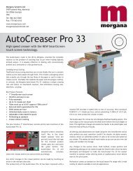
Control Box ...............................................................Fig 13.12<br />
13.1 .....Control Box<br />
The control box contains all the printed circuit boards that operate<br />
the machine. The box is removed as follows:- Switch off the power<br />
supply. Remove the operator side cover. Dis-connect the plugs<br />
from the rear of the control box. Remove the two screws located at<br />
SYSTEMS PAGE 39