thermal energy metering system - general catalogue
thermal energy metering system - general catalogue
thermal energy metering system - general catalogue

You also want an ePaper? Increase the reach of your titles
YUMPU automatically turns print PDFs into web optimized ePapers that Google loves.
19<br />
Thermal <strong>energy</strong> <strong>metering</strong> – M-Bus meters of <strong>thermal</strong> power plant<br />
Technical data<br />
• In compliance with 2004/22/CE (MID) Directive<br />
• Fluid temperature range 10-130°C<br />
• Direct reading through LC display<br />
• Integrated M-Bus module<br />
• Double impulse inlet for sanitary impulse meters<br />
• Double register for heating and conditioning<br />
• 2 PT500 platinum temperature probes (EN60751)<br />
• 2 probe housings<br />
• Lithium battery supply > 6 years<br />
• IP54 protection degree (electronic unit)<br />
• Metrology Class 2 according to UNI EN1434<br />
• Environmental Class A according to UNI EN1434<br />
• CE marking<br />
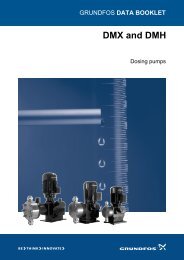
ULTRASOUND M-Bus METERS FOR USE IN THERMAL POWER PLANT.<br />
Ultrasound <strong>thermal</strong> <strong>energy</strong> meters for use in <strong>thermal</strong> power plant. Composed of a processing<br />
electronic unit, a measurement section of the capacity, two PT500 temperature probes for<br />
measurement of the delivery and return temperature of water. Available with threaded (size 1<br />
1/4” or 2”) and flanged connection (from DN25 to DN100). Possibility of “split” mounting with<br />
electronic unit separated by the measurement section of the capacity. The meters are equipped<br />
with double impulse inlet to centralize up to two sanitary meters of <strong>thermal</strong> power plant<br />
with impulse outlet. All meters are in compliance with 2004/22/CE (MID) Directive and have<br />
integrated M-Bus module.<br />
THREADED CONNECTION<br />
PART NUMBER<br />
CONNECTION<br />
NOM. CAP<br />
(qp) m³/h<br />
MIN. CAP<br />
(qi) m³/h<br />
MAX. CAP.<br />
(qs) m³/h<br />
LOSS OF PRESSURE<br />
(a qp) mbar<br />
SUPPLY<br />
DISTANCE BETWEEN<br />
THE AXIS mm<br />
GE552Y131 1” 1/4 3,5 0,035 7 65 Battery 260<br />
GE552Y133 1” 1/4 6,0 0,06 12 150 Battery 260<br />
GE552Y135 2” 10,0 0,1 20 120 Battery 300<br />
FLANGED CONNECTION<br />
PART NUMBER<br />
FLANGE<br />
NOM. CAP<br />
(qp) m³/h<br />
MIN. CAP<br />
(qi) m³/h<br />
MAX. CAP.<br />
(qs) m³/h<br />
LOSS OF PRESSURE<br />
(a qp) mbar<br />
SUPPLY<br />
DISTANCE BETWEEN<br />
THE AXIS mm<br />
GE552Y139 DN25 6,0 0,06 12 150 Battery 260<br />
GE552Y141 DN40 10,0 0,1 20 120 Battery 300<br />
GE552Y143 DN50 15,0 0,15 30 120 Battery 270<br />
GE552Y145 DN65 25,0 0,25 50 70 Battery 300<br />
GE552Y147 DN80 40,0 0,4 80 120 Battery 300<br />
GE552Y149 DN100 60,0 0,6 120 140 Battery 360