Polymers & Lasers - Laser Application Center - VESTAKEEP?
Polymers & Lasers - Laser Application Center - VESTAKEEP?
Polymers & Lasers - Laser Application Center - VESTAKEEP?

Create successful ePaper yourself
Turn your PDF publications into a flip-book with our unique Google optimized e-Paper software.
<strong>Polymers</strong> & <strong><strong>Laser</strong>s</strong><br />
<strong>Laser</strong> <strong>Application</strong> <strong>Center</strong>
Performance<br />
<strong>Polymers</strong><br />
<strong>Laser</strong> <strong>Application</strong> <strong>Center</strong>
Contents<br />
Introduction……………………………………………………………….<br />
High Performance <strong>Polymers</strong> from Evonik……………………………<br />
<strong>Laser</strong> <strong>Application</strong> <strong>Center</strong> ………………………………………………<br />
<strong>Laser</strong> Technolgy …………………………………………………………<br />
What is laser radiation……………………………………………………<br />
Types of <strong>Laser</strong>……………………………………………………………<br />
Solid-State <strong><strong>Laser</strong>s</strong>…………………………………………………………<br />
Semiconductor <strong><strong>Laser</strong>s</strong>……………………………………………………<br />
Gaslaser ……………………………………………………………………<br />
Other Types of <strong>Laser</strong>………………………………………………………<br />
<strong>Polymers</strong> and <strong><strong>Laser</strong>s</strong> ……………………………………………………<br />
Requirements ………………………………………………………………<br />
Factors Influencing <strong>Laser</strong>-Welding of Plastics……………………………<br />
Optical Properties of Plastics………………………………………………<br />
Transmission Spectra………………………………………………………<br />
<strong>Laser</strong>-Marking ……………………………………………………………<br />
Factors Impacting <strong>Laser</strong>-Marking…………………………………………<br />
<strong>Laser</strong>-Marking Non-Transparent Plastics.……………………………<br />
Marking <strong><strong>Laser</strong>s</strong> ……………………………………………………………<br />
Lettering and Contrast on Non-Transparent Plastics………………<br />
<strong>Laser</strong>-Marking of Transparent Plastics ………………………………<br />
<strong>Laser</strong>-Marking by NIR Absorbers…………………………………………<br />
2D <strong>Laser</strong>-Marking of Transparent Plastics …………………………<br />
3D Sub-Surface <strong>Laser</strong>-Engraving of Transparent Plastics…………<br />
Basics of 3D Sub-Surface <strong>Laser</strong>-Engraving …………………………<br />
6<br />
7<br />
8<br />
9<br />
9<br />
11<br />
12<br />
13<br />
13<br />
13<br />
14<br />
14<br />
15<br />
16<br />
17<br />
18<br />
18<br />
19<br />
19<br />
20<br />
21<br />
21<br />
23<br />
24<br />
25
3D Sub-Surface <strong>Laser</strong>-Engraving of Transparent Plastics…………<br />
3D <strong>Laser</strong> for Sub-Surface Engraving……………………………………<br />
26<br />
27<br />
Advantages of <strong>Laser</strong>-Sensitive, Transparent,<br />
Colorless Plastics.…………………………………………………………<br />
Advantages of <strong>Laser</strong>-Marking.…………………………………………<br />
<strong>Laser</strong>-Welding of Plastics.………………………………………………<br />
Degrees of Difficulty in <strong>Laser</strong>-Welding.………………………………….<br />
The <strong>Laser</strong>-Welding Process.……………………………………………<br />
Weld Seam Quality.………………………………………………………<br />
Factors affecting weld seam quality in thermoplastics.………………….<br />
<strong>Laser</strong>-Welding Processes.……………………………………………….<br />
Contour Welding.…………………………………………………………..<br />
Simultaneous Welding.…………………………………………………….<br />
Quasi Simultaneous Welding.……………………………………………..<br />
Mask Welding.……………………………………………………………...<br />
<strong>Application</strong> Areas…..………………………………………………………<br />
Advantages.…………………………………………………………………<br />
<strong>Laser</strong>-Structuring.………………………………………………………..<br />
<strong>Laser</strong>-Sintering.…………………………………………………………...<br />
Requirements on <strong>Laser</strong>-Processable Molding Compounds.………<br />
<strong>Application</strong> Profiles <strong>Laser</strong>-Marking.……………………………………...<br />
<strong>Application</strong> Profiles <strong>Laser</strong>-Welding.………………………………………<br />
Requirements on <strong>Laser</strong>-Workable Molding Compounds.………………<br />
Requirements Profile <strong>Laser</strong>-Structuring.…………………………………<br />
27<br />
28<br />
29<br />
30<br />
31<br />
32<br />
32<br />
33<br />
33<br />
33<br />
34<br />
34<br />
35<br />
35<br />
36<br />
37<br />
38<br />
38<br />
38<br />
38<br />
38
<strong>Laser</strong> Additives.…………………………………………………………...<br />
Additives for Non-Transparent Molding Compounds.………………….<br />
Additives for (Highly) Transparent, Colorless Molding Compounds.…<br />
<strong>Laser</strong>-Processable Molding Compounds.…………………………….<br />
VESTODUR ® ..................................................................................<br />
VESTORAN ® ..................................................................................<br />
TROGAMID ® .................................................................................<br />
VESTAMID ® ...................................................................................<br />
<strong>VESTAKEEP</strong> ® .................................................................................<br />
<strong>Laser</strong>-Processable Semifinished Products.…………………………..<br />
EUROPLEX ® ...................................................................................<br />
PLEXIGLAS ® ..................................................................................<br />
Environmental Aspects.………………………………………………….<br />
Emissions.…………………………………………………………………...<br />
Recycling.……………………………………………………………………<br />
Quality.……………………………………………………………………..<br />
Future Prospects.…………………………………………………………<br />
Classes of <strong><strong>Laser</strong>s</strong>.…………………………………………………………<br />
DIN EN 60825-1 Classification.…………………………………………..<br />
Literature and Sources.…………………………………………………..<br />
39<br />
39<br />
39<br />
40<br />
40<br />
40<br />
41<br />
41<br />
41<br />
42<br />
42<br />
42<br />
43<br />
43<br />
43<br />
43<br />
44<br />
45<br />
45<br />
46
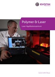
Performance <strong>Polymers</strong><br />
Introduction<br />
<strong>Application</strong> possibilities for laser systems<br />
used in processing plastics are virtually<br />
unlimited. Fast, flexible, and precise, laser<br />
technology is more cost efficient than<br />
conventional processes; moreover, this<br />
advanced technology brings innovative<br />
ideas to rapid implementation and adds<br />
years to the life of processed materials.<br />
Where products are marked with barcodes,<br />
contour sharpness is important, as<br />
is contrast. Only if the marking stands out<br />
clearly from the material surface can it be<br />
correctly read by a bar code scanner and<br />
processed further.<br />
The miniaturization of components and<br />
their increasingly complex geometries<br />
require welds of such fineness that conventional<br />
welding processes can obtain<br />
them only with great difficulty, if at all.<br />
The laser-welding process, on the other<br />
hand, makes it possible to do even threedimensional<br />
welding in a single workstep.<br />
In the manufacture of sensors for medical<br />
engineering, the laser can produce the finest<br />
welds in the most confined of spaces.<br />
The conventional manufacture of threedimensional<br />
circuit substrates depends<br />
on product-specific tools for creating the<br />
printed circuit structure on the component,<br />
which severely limits the flexibility<br />
of the processes when designs are changed.<br />
Further miniaturizing printed circuit<br />
structures on MID components requires<br />
additional time and cost. Using special<br />
molding compounds in conjunction with<br />
the appropriate laser-structuring technology<br />
offers a flexible and cost-effective<br />
alternative.<br />
In design studies, modeling, and even in<br />
very small-scale production, parts are still<br />
often produced manually because the high<br />
cost of tools rules out the fabrication of<br />
injection-molded parts. <strong>Laser</strong>-sintering<br />
offers an economical alternative here. The<br />
parts need only be developed on a CAD<br />
system and then constructed as hardware<br />
in a subsequent rapid prototyping process.<br />
The scope of application of plastics depends<br />
strongly on their material properties<br />
and their compatibility with the laser<br />
wavelengths used in the various systems.<br />
Not all of the currently used thermoplastics<br />
absorb laser beams equally well. But<br />
thanks to special additives developed<br />
and patented by Evonik’s Performance<br />
<strong>Polymers</strong> and Inorganic Materials Business<br />
Units, our molding compounds can be adjusted<br />
for use in an extremely wide range<br />
of applications.<br />
The components made from these<br />
molding compounds ensure good laser<br />
weldability of two transparent materials<br />
and, for laser-marking, dark lettering of<br />
the highest quality, even for highly transparent<br />
and colorless plastics. Moreover,<br />
the High-Performance <strong>Polymers</strong> Business<br />
Line offers various black and dark-colored<br />
products that can be laser-marked to give<br />
light-on-dark images with good contrast.<br />
For the selection of a suitable laser-processable<br />
material, the requirements profile<br />
for the molded part must be known. The<br />
following table of laser-processable<br />
molding compounds from our highperformance<br />
polymers product range will<br />
help you draw up a short list of suitable<br />
materials. We recommend that you<br />
consult us as your knowledgeable partner<br />
before beginning a new project. Our <strong>Laser</strong><br />
<strong>Application</strong> <strong>Center</strong> has the skills to select<br />
the molding compounds that are optimal<br />
for you, and to identify fast and economical<br />
processing options when these materials<br />
are used.<br />
6
High Performance <strong>Polymers</strong> from Evonik<br />
<br />
<br />
<br />
<br />
<br />
<br />
<br />
<br />
<br />
<br />
<br />
<br />
<br />
<br />
<br />
<br />
<br />
<br />
<br />
<br />
<br />
7
<strong>Laser</strong> <strong>Application</strong> <strong>Center</strong><br />
Solution Provider<br />
High Performance<br />
<strong>Polymers</strong>:<br />
Polymer Materials<br />
<strong>Laser</strong> Sintering<br />
<strong>Laser</strong> Printing<br />
<strong>Laser</strong> Engraving<br />
<strong>Laser</strong> Welding<br />
<strong>Laser</strong> Direct Structuring<br />
Industrial<br />
Partners:<br />
<strong>Laser</strong> Technologies<br />
Customers:<br />
Problems<br />
<strong>Application</strong>s<br />
The <strong>Laser</strong> <strong>Application</strong> <strong>Center</strong> of High Performance <strong>Polymers</strong> offers support in the use of lasers with polymers, in the form of:<br />
• comprehensive advice,<br />
• state-of-the-art technology, and<br />
• quality testing<br />
<strong>Polymers</strong> & <strong><strong>Laser</strong>s</strong><br />
The <strong>Laser</strong> <strong>Application</strong> <strong>Center</strong> supports you in choosing<br />
materials for all relevant laser processes.<br />
You are welcome to try out the following laser applications<br />
at the <strong>Center</strong>:<br />
• <strong>Laser</strong>-marking (2D and 3D)<br />
• <strong>Laser</strong>-welding<br />
• <strong>Laser</strong>-sintering<br />
• <strong>Laser</strong>-structuring<br />
Quality<br />
In our testing and analytical laboratories, we can<br />
perform a wide range of tests on lasered and unlasered<br />
materials to check and safeguard our high<br />
quality standards. These include<br />
• transmission measurements,<br />
• haze,<br />
• scanning electron microscopy (SEM),<br />
• transmission electron microscopy (TEM),<br />
• light microscopy, and<br />
• tensile testing<br />
as well as many other physical and chemical tests.<br />
8
<strong>Laser</strong> Technology<br />
What is laser radiation<br />
The word laser is an acronym for Light Amplification<br />
by Stimulated Emission of Radiation, and describes<br />
a physical process leading to the production of laser<br />
radiation.<br />
In the first step, atoms 1) of a laser medium (the active<br />
medium) are excited by supplying them with energy,<br />
a process known as “pumping” (see diagram). The<br />
active medium may be a liquid, solid, or gas.<br />
Depending on the active medium, the energy can be<br />
supplied by electrical gas discharges, flash lamps, an<br />
applied voltage, or another laser. The excited atoms<br />
emit photons (light particles), thereby returning to<br />
the non-excited state. If these light particles collide<br />
with other atoms in the excited state, the latter also<br />
emit light particles of the same wavelength, phase,<br />
and direction as the incident light particles. This process,<br />
known as “stimulated emission,” is what occurs<br />
in an optical resonator.<br />
laser pumping energy<br />
laser beam<br />
active medium<br />
optical resonator<br />
end mirror<br />
(totally reflecting)<br />
front mirror<br />
(partly transparent)<br />
Fig. 1: Structure of a laser<br />
The resonator may be, for example, a (gas-filled) tube<br />
or a solid (such as ruby, or a semiconductor), at both<br />
ends of which a mirror reflects the radiation. This<br />
therefore traverses the active medium many times,<br />
stimulating further atoms to give up their light particles<br />
on each pass. One of the two mirrors is partly<br />
transparent, so that part of the radiation can emerge<br />
from the tube.<br />
<strong>Laser</strong> radiation differs essentially from radiation<br />
emitted by conventional radiation sources, such as<br />
incandescent lamps, in the following ways:<br />
• coherence: the waves possess a constant phase difference; they are temporally and spatially coherent;<br />
• monochromatic light: laser radiation has exactly one wavelength;<br />
• low divergence: lasers emit bundled, almost parallel radiation.<br />
1)<br />
These may be atoms, molecules, or ions; for the sake of brevity they will be referred to in the following as atoms<br />
9
IR<br />
light source prism spectrum<br />
UV<br />
• “white” light, emitting a broad spectrum<br />
• luminous power of the order of mW to W<br />
• not coherent<br />
• omnidirectional radiation<br />
• monochromatic (a single color)<br />
• luminous power of the order of mW to MW<br />
• spatially and temporally coherent<br />
• directional “laser beam” radiation<br />
• good bundling (focusing) of the beam<br />
Fig. 2: Normal light<br />
Fig. 3: <strong>Laser</strong> light<br />
In practice, this means that laser beams can be strongly bundled and easily focused on the smallest spaces. This property is exploited<br />
in every CD player, for example, to read out the microscopically small structures on the CD. On the other hand, laser beams also<br />
allow enormous energies to be bundled at a single point, for example, for very precise cutting, marking, or welding of materials.<br />
Because lasers are used for a wide range of different purposes, they differ also in their structure. The wavelengths range from the far<br />
infrared (IR) region through visible light to the ultraviolet (UV) region (see Fig. 4).<br />
Fig. 4: The electromagnetic spectrum<br />
10
Types of <strong>Laser</strong><br />
<strong><strong>Laser</strong>s</strong> are categorized and named according to the type of the optically active material used; they may be gas, solid, or liquid (or dye)<br />
lasers (Fig. 5).<br />
Fig.5: Typical lasers and their wavelengths<br />
<strong><strong>Laser</strong>s</strong> can also be classified according to whether they radiate continuously (cw (continuous wave) lasers, Fig. 6) or operate in a<br />
pulsed mode. <strong><strong>Laser</strong>s</strong> radiating for a period exceeding 0.25 s are known as continuous wave lasers. Pulsed lasers emit radiation pulses<br />
at regular intervals; the duration of these pulses may range from a few femtoseconds to 0.25 seconds (Fig. 7).<br />
P L<br />
= laser power (W) P S<br />
= peak power (W) P m<br />
= mean power (W)<br />
T = pulse period<br />
t p<br />
= pulse duration<br />
T<br />
P L<br />
t P<br />
Power (P)<br />
Power (P)<br />
P S<br />
P m<br />
Time(t)<br />
Time (t)<br />
Fig. 6: Continuous wave (cw) laser<br />
Fig. 7: Pulsed laser<br />
11
Solid-State <strong><strong>Laser</strong>s</strong><br />
Examples of Doping Materials<br />
), doped with Nd 4<br />
The first working laser was a ruby laser, made from<br />
• Yttrium vanadate (YVO<br />
ruby (chromium-doped corundum), developed by<br />
Maiman in the year1960.<br />
• The doping material in the first ever laser, the<br />
Solid-state laser materials are commonly made by<br />
doping a crystalline solid host with ions provide the<br />
required energy states. Embedded in the host material,<br />
•<br />
ruby laser (694.3 nm, red), was chromium. Because<br />
of its low efficiency it is now rarely used.<br />
Neodymium, is used in the most important comorbitals<br />
these ions form the actual active medium. Their<br />
do not participate in chemical bonding. The<br />
carrier material (host crystal or glass) therefore has<br />
only a small influence on the properties of the ions. •<br />
mercial solid-state lasers, Nd:YAG at 1064 nm<br />
(infrared) and double frequency at 532 (green).<br />
Nd:glass and Nd:YLF are also possible.<br />
Ytterbium, allows high efficiency (>50%) in la-<br />
Solid-state lasers are distinguished according to the<br />
type and form of the host material and the doped<br />
elements.<br />
•<br />
ser operation, but needs narrow-band pumping<br />
with laser diodes (940 nm). The most important<br />
material with this dopant is the Yb:YAG laser, for<br />
example, highly doped as a thin disk laser with a<br />
wavelength of 1030 nm.<br />
Titanium; an important mode-coupled solid-sta-<br />
Examples of host or carrier materials<br />
te laser is the titanium:sapphire laser, 670-1100<br />
nm (red-infrared), which due to broadband<br />
• Glass (in the form of rods or fiber lasers)<br />
amplification is suitable for pulses in the fs range.<br />
• Advantage: simple to produce, even in large • Erbium, 3 μm, pumping with diode laser at 980<br />
dimensions<br />
nm; known as the eye-safe laser, this is used for<br />
• Disadvantages: low thermal conductivity,<br />
laser range finders and in medicine.<br />
low strength<br />
• Al (corundum, sapphire; e.g., ruby laser<br />
2 3<br />
Types of Active Media<br />
(chromium doped), titanium:sapphire laser)<br />
• Advantages: high thermal conductivity,<br />
• Rod lasers<br />
high strength<br />
• Microcrystal lasers<br />
• Disadvantages: relatively high absorption; • Slab lasers<br />
expensive<br />
• Fiber lasers<br />
• YAG (yttrium aluminum garnet laser: see<br />
• Thin disk lasers<br />
Nd:YAG laser), doped with Nd, Er, Yb<br />
• Advantages: high thermal conductivity,<br />
high strength, low absorption<br />
• Disadvantage: expensive<br />
12
Semiconductor <strong><strong>Laser</strong>s</strong><br />
In semiconductor lasers, the active medium is the diffusion<br />
zone of the charge carriers in a p-n transition 1)<br />
of a semiconductor crystal. The optical resonator can<br />
be formed here by the end faces of the semiconductor<br />
crystal, because the high refractive index of the<br />
crystal results in high reflectivity.<br />
<strong>Laser</strong> diodes are directly electrically pumped lasers.<br />
The power of laser diodes lies between < 1W and<br />
10W. The beam quality declines with increasing<br />
power.<br />
A number of individual diodes can be assembled side<br />
by side on a single narrow chip (approx. 0.1 x 1 x 10<br />
mm). These “bars”, as they are known, can supply<br />
more than 50 watts if mounted on a heat sink, with<br />
the individual diodes electrically connected in parallel.<br />
The mounted bar is also known as a “submount.”<br />
By coupling a number of bars or submounts in a stack,<br />
outputs in the kW range can be achieved, with correspondingly<br />
poor beam quality. By the use of different<br />
(normally up to 3) wavelengths and polarization<br />
directions, up to 6 stacks can be optically added with<br />
low losses and without deterioration of beam quality.<br />
For optical pumping of solid-state lasers by laser diodes,<br />
the pump wavelength must be matched exactly<br />
and wavelength coupling is therefore not possible.<br />
However, the diode lasers need not be combined here<br />
into beams with high power density.<br />
Diode lasers with wavelengths in the range of approx.<br />
800 nm to 1000 nm are now, in addition to Nd:YAG<br />
lasers (1064 nm), the most important industrial lasers<br />
for processing of plastics.<br />
Other semiconductor lasers include:<br />
• optically pumped semiconductor lasers, including<br />
semiconductor thin disk lasers,<br />
• quantum cascade lasers,<br />
• surface-emitting lasers (VCSEL) (optically as<br />
well as electrically pumped), and<br />
• tunable lasers (tunable laser source, TLS) with<br />
adjustable wavelength.<br />
Gas <strong><strong>Laser</strong>s</strong><br />
In gas lasers the active medium is gaseous. Gas lasers<br />
are usually electrically pumped by a gas discharge in<br />
the active medium itself.<br />
The most important gas lasers used in the processing<br />
of polymers are:<br />
• the carbon dioxide (CO ) laser, with wavelength<br />
2<br />
approx. 10.6 μm (mid-infrared), an important<br />
industrial laser for cutting and marking, and<br />
• the excimer laser, for example, KrF (248 nm),<br />
XeF (351-353 nm), ArF (193 nm), XeCl (308<br />
nm), and F 2<br />
(157 nm), for marking and fine<br />
drilling; all these are ultraviolet.<br />
Other Types of <strong>Laser</strong><br />
Other types of lasers include, for example, dye lasers,<br />
color center lasers, and free-electron lasers (FEL).<br />
1)<br />
p-n (positive-negative) transition is the boundary layer between a p-conducting and an n-conducting region in a semiconductor. The strong concentration gradient<br />
of the carriers at the boundary layer causes some holes to diffuse from the p- to the n-conducting layer, and some electrons in the reverse direction, where they<br />
then recombine with the respective carriers.<br />
13
<strong>Polymers</strong> and <strong><strong>Laser</strong>s</strong><br />
Requirements<br />
Virtually any plastic can be laser processed, but material- and process-specific restrictions must be taken into account.<br />
Plastics do not absorb laser radiation in the region extending from the near ultraviolet to the near infrared. Conversion of laser energy<br />
into heat (of fusion) is therefore possible only if the polymer has been appropriately “laser sensitized” by addition of an additive.<br />
In the absence of laser additives, therefore, polymers can be processed only in far ultraviolet light, for example, with excimer lasers,<br />
and in far infrared light, for example, with CO 2<br />
lasers (Fig. 8).<br />
Electronic excitation<br />
Electron excitation<br />
Vibronic excitation<br />
Molecular excitation<br />
Absorption<br />
Additives<br />
<strong>Polymers</strong><br />
Ultra violet<br />
visible Visible region<br />
Infrared<br />
400 nm 700 nm<br />
Nd:YAG/SHG<br />
Nd:YAG<br />
532 nm<br />
1064 nm<br />
Diode laser<br />
808, 940, 980 nm<br />
CO 2<br />
10.6 µm<br />
10.6 μm<br />
Fig. 8: Light absorption of polymers and laser wavelengths<br />
If plastics are used for laser-welding, the material-specific properties of the various types of plastics must be taken into particular<br />
consideration.<br />
Thermoplastics, whether amorphous or semicrystalline, are easily fusible and have a fusion temperature range above which they<br />
decompose (Fig. 9).<br />
In addition to morphology, fillers, such as glass fibers, also affect welding properties.<br />
14
Factors Influencing <strong>Laser</strong>-Welding of Plastics<br />
Crosslinked plastics of the thermoset and elastomer class (except for thermoplastic elastomers, TPE/TPU) are not fusible. They are<br />
therefore not suitable for laser-welding. They can, however, be used for laser-marking.<br />
Fusion/softening ranges<br />
Decomposition temperature<br />
ABS<br />
PA6<br />
PA66<br />
PA11<br />
PA12<br />
PA612<br />
PA6-3-T<br />
PA PACM 12<br />
PBT<br />
PC<br />
HD-PE<br />
PEEK<br />
PMMA<br />
POM<br />
PP<br />
PPSU<br />
PS<br />
PSU<br />
PTFE<br />
PVC<br />
SAN<br />
TPA<br />
TPU<br />
100 150 200 250 300 350 400 450 500<br />
Temperature C<br />
Fig. 9: Fusion and softening ranges of plastics<br />
15
Optical Properties of Plastics<br />
When a laser beam strikes a plane interface between two media with different refractive indices, it is partly reflected at the interface<br />
and partly absorbed on penetration, the remaining radiation then being transmitted. The proportion in which these effects occur<br />
depends on the material properties of the obstacle; the sum of all radiations is always 100%.<br />
<strong><strong>Laser</strong>s</strong>trahl<br />
<strong>Laser</strong> beam<br />
Ф in<br />
Reflection<br />
Reflektion<br />
α<br />
β<br />
Absorption<br />
Absorbtion<br />
Plastic<br />
Kunststoff<br />
Ф ex<br />
Transmission<br />
Fig. 10: Optical properties of plastics<br />
Absorption<br />
Absorption (from the Latin absorptio) occurs when<br />
power from the light beam is transferred to the<br />
plastic. The absorbed fraction of the light is generally<br />
converted into heat, but may also be lost through<br />
scattering at defects (air, etc.) in the structure of the<br />
material (Fig. 10).<br />
<strong>Polymers</strong> do not absorb laser radiation in the region<br />
from the ultraviolet to the infrared. Conversion of<br />
laser energy into heat (of fusion) is therefore possible<br />
only if the polymer has been “laser sensitized” by<br />
addition of an appropriate additive (Fig. 8).<br />
Reflection<br />
Reflection (from the Latin reflectere, to bend back,<br />
or turn) occurs when, for example, electromagnetic<br />
waves are bounced back from a surface (Fig. 10).<br />
The ratios of the refractive indices and absorption<br />
coefficients of the plastics determine the intensities<br />
of reflection and transmission. For reflection, the<br />
following simple law (for plane surfaces) applies: the<br />
angle of incidence (α) of the light beam equals the<br />
angle of reflection (β).<br />
Scattering<br />
Scattering of electromagnetic waves occurs mainly<br />
at defects in the structure of materials, caused by, for<br />
example, poor distribution of additives, bubbles (air<br />
pockets), etc.<br />
Haze<br />
Haze is the scattered component of the transmitted<br />
light in transparent plastics. Low haze values therefore<br />
indicate high transparency.<br />
Transmission<br />
Transmission (from the Latin trans (through) and<br />
mittere (send)) is a measure of the transparency of<br />
a medium to, for example, electromagnetic waves<br />
(light, etc.) (Fig. 10).<br />
16
Transmittance<br />
In optics, transmittance is the proportion of the incident radiation<br />
or light flux that completely penetrates a transparent component.<br />
The transmittance τ is defined as the quotient of the radiant flux<br />
of the emergent (transmitted) light beam (Ф ex<br />
) and that of the<br />
incident beam (Ф in<br />
).<br />
τ = Ф ex<br />
/Ф in<br />
The transmittance depends on, among other factors, the<br />
wavelength and therefore the frequency of the electromagnetic<br />
radiation, that is, on the color of the light, and on the angle of<br />
incidence of the wave.<br />
Transmission Spectra<br />
Fig. 11:<br />
Transmission spectrum of<br />
nanomodified PMMA<br />
Fig. 12:<br />
Transmission spectrum of<br />
nanomodified TROGAMID® CX7323<br />
17
<strong>Laser</strong>-Marking<br />
The range of potential applications for laser systems<br />
in the marking of plastics is virtually unlimited. Fast,<br />
flexible, and precise, laser technology is more economical<br />
than the conventional printing and injection<br />
molding processes; moreover, this advanced technology<br />
guarantees the durability and contour sharpness<br />
of the marking.<br />
For marking products with a barcode or data matrix<br />
code, contrast is important, as is contour sharpness;<br />
only when the marking stands out clearly from the<br />
material surface can it be correctly read by the bar<br />
code scanner and processed further.<br />
The contrast and contour sharpness of laser markings<br />
depend on the material properties of the plastics used<br />
and their compatibility with the various laser systems<br />
and their wavelengths. Not all of the commonly used<br />
thermoplastics absorb laser beams equally well, and<br />
this can negatively impact the contrast or suppress it<br />
altogether.<br />
Marking plastics in the UV, visible, and IR ranges<br />
is possible either directly or with the use of laser<br />
additives.<br />
Because the Nd:YAG laser (1064 nm, Fig. 13) is<br />
the most commonly used in practice, most molding<br />
compounds for laser-marking are now formulated for<br />
the wavelength of this laser. Exceptionally high contrast<br />
is achieved when the materials contain special<br />
additives developed and patented by Evonik’s High<br />
Performance <strong>Polymers</strong> Business Line. <strong>Laser</strong> additives<br />
designed specially for transparent plastics have also<br />
been developed by the company’s Inorganic Materials<br />
Business Unit.<br />
In non-transparent plastics, these laser additives<br />
ensure dark markings of the highest quality on almost<br />
all light-colored formulations, irrespective of the<br />
pigmentation of the plastic and even for in-house<br />
coloring by customers. Additionally, the High Performance<br />
<strong>Polymers</strong> Business Line offers various darkcolored<br />
and black products that can be laser-marked<br />
in light colors with good contrast.<br />
Highly transparent plastics from Evonik that contain<br />
laser additives are distinguished by their absolute<br />
colorlessness and very low haze. In this case also,<br />
the lettering is of the highest quality, with very good<br />
contrast.<br />
To choose an appropriate laser-markable material,<br />
you must know the requirements profile for the part<br />
to be marked.<br />
Factors Impacting <strong>Laser</strong>-Marking<br />
The markability of a plastic depends only on its material<br />
properties and any laser additive used. Marking<br />
effects such as color change, foaming, and carbonization<br />
depend on the reciprocal effects of material<br />
properties and laser wavelength. The characteristics<br />
crucially important for high-quality marking are<br />
homogeneity of the molding compound, excellent<br />
distribution of the laser additive, and appropriate<br />
selection of laser parameters.<br />
Fig. 13:<br />
Nd:YAG marking laser<br />
1064 nm (from Baasel-<strong>Laser</strong>technik)<br />
18
<strong>Laser</strong>-Marking Non-Transparent Plastics<br />
Marking <strong><strong>Laser</strong>s</strong><br />
Writing laser<br />
The writing laser offers flexibility. The laser beam is<br />
deflected in the x- and y-directions by two computer<br />
controlled galvanometer mirrors, and is focused with<br />
a lens on the part to be marked. An area of approximately<br />
10 x 10 cm can be marked at any required<br />
point. It is possible to provide every single part in a<br />
production line with an individual marking, such as a<br />
serial number.<br />
Mask <strong>Laser</strong><br />
The mask laser is not as flexible as the writing laser,<br />
but is considerably faster. The laser beam, a few<br />
square centimeters in area, passes through a lens,<br />
imaging a mask on the part to be marked. This process<br />
allows up to 200 markings per second.<br />
CAD-SYSTEM<br />
<strong>Laser</strong><br />
Deflection unit for<br />
the x direction<br />
Mask<br />
Deflection mirror<br />
Lens<br />
Deflection unit for<br />
the y direction<br />
Lens<br />
Workpiece<br />
Workpiece<br />
Fig. 14:<br />
Writing laser<br />
Fig.15:<br />
Mask laser<br />
Dot-Matrix-Process<br />
In the dot matrix process, a laser beam is “chopped” by a rotating mirror. By movement of the part to be marked, a marking consisting<br />
of a number of individual points is produced, in the same manner as on an inkjet printer. This process represents a special form of<br />
laser-marking of plastics because it can be used for only a few thermoplastics.<br />
The Dot-Matrix-Process is suitable for batch date marking at high speed. The size of the marking is restricted, however, and marking<br />
is possible only with moved parts.<br />
19
Lettering and Contrast on<br />
Non-Transparent Plastics<br />
The staining depth and foaming height can be determined<br />
from light microscopic images of thin sections<br />
(Fig. 16, 17, and 18). The staining depth [a] should<br />
be at least 100 μm, and the foaming height [b] should<br />
be as low as possible. The most important parameter<br />
characterizing the marking is the legibility, which can<br />
be quantified in terms of contrast; this can be determined<br />
using a luminance meter.<br />
To eliminate gloss angle effects, the measurement<br />
point is illuminated by an integrating sphere with a<br />
luminosity of 200 lux. The luminances of the background<br />
(BL) and characters (CL) are determined,<br />
and the contrast C is defined by the ratio BL/CL. The<br />
GS-VWSG7 test standards of the Employers’ Liability<br />
Insurance Association specify that for characters on<br />
key caps C must be > 3.<br />
Fig. 16: Contrast without additive<br />
Fig. 17: Contrast with additive<br />
Fig. 19:<br />
No additive; high<br />
foaming height<br />
Fig. 18: Characterization of laser-marking by<br />
evaluation of staining depth (a) and foaming<br />
height (b)<br />
Fig. 20:<br />
Low foaming height<br />
achieved by use of an<br />
additive<br />
Surface profile of the letter “E” with the same laser<br />
energy<br />
20
<strong>Laser</strong>-Marking of Transparent Plastics<br />
<strong>Laser</strong>-marking of transparent plastics has so far been restricted to colored thermoplastics; selective coupling in<br />
of the laser energy was not formerly possible in transparent plastics. The problem could be solved by the use of<br />
suitable additives or pigments, but at the cost of transparency and colorlessness. Evonik’s technicians have now<br />
overcome these difficulties and have succeeded in extending the process also to transparent polymers.<br />
<strong>Laser</strong>-Marking by NIR Absorbers<br />
A technology has been successfully developed for<br />
laser-marking transparent plastics, which are otherwise<br />
difficult or impossible to mark with lasers. This<br />
uses nanoscale metal oxides, which, on account of<br />
their small particle size, do not scatter visible light but<br />
absorb the wavelength of the laser in the near infrared<br />
(NIR) region. Because the Nd:YAG laser (1,064<br />
nm) is most commonly used in practice, the additives<br />
have been formulated for the wavelength of this laser.<br />
The skill in the incorporation of the metal oxides lies<br />
in controlling their tendency to agglomeration and<br />
dispersing them as homogeneously as possible in<br />
the polymer matrix. Only under these conditions can<br />
high-contrast markings with the highest resolution<br />
and contour sharpness be obtained. These infrared<br />
absorbers are dispersed in PLEXIGLAS ® (polymethyl<br />
methacrylate, PMMA) and TROGAMID ® , a transpa-<br />
rent polyamide, new compounding processes being<br />
used for this purpose.If a laser beam now falls on the<br />
metal oxides, they absorb the energy and heat their<br />
immediate environment, which results in foaming<br />
(by formation of gaseous degradation products in the<br />
micrometer region) or carbonization (degradation<br />
to carbon). The result is a locally confined change of<br />
refractive index, rendering the marking, such as an<br />
inscription, visible. The additives do not produce a color<br />
change, but appear in a shade of gray ranging from<br />
white to black, depending on the polymer and the<br />
choice of laser parameters. In both PLEXIGLAS ® and<br />
TROGAMID ® , markings can be obtained with layer<br />
thicknesses of less than 100 micrometers. Multilayer<br />
designs are also possible in which the laser-sensitive<br />
layer is embedded between two transparent covering<br />
layers.<br />
Well-dispersed laser sensitive additive<br />
Aggregated laser-sensitive additive<br />
Fig: 21<br />
Dispersion of NIR absorber<br />
21
Use of nanoscale NIR absorbers<br />
in transparent polymers such<br />
as PLEXIGLAS ® (PMMA)<br />
or<br />
TROGAMID ® (PA)<br />
for laser-marking or subsurface<br />
engraving<br />
Focused laser beam<br />
Nanoscale particles absorb in the<br />
NIR<br />
Polymer foams<br />
Polymer carbonizes<br />
Change of refractive index or<br />
carbonization makes the marking<br />
visible<br />
Fig. 22: Mechanism of laser-marking and sub-surface<br />
engraving by NIR absorbers<br />
The possible fields of application of this new technology<br />
for laser-marking (highly) transparent<br />
plastics are many and varied. Because the marking is<br />
forgery-proof and highly durable, it is suitable for, for<br />
example, identity cards, barcodes, and pharmaceutical<br />
packaging. Medical technology could also benefit<br />
from this contactless process because, in contrast to<br />
other marking processes such as printing or milling,<br />
there are no impurities and no contamination with<br />
chemical compounds or abrasion particles.<br />
Entirely different fields of application, such as personalized<br />
art objects or inscriptions for office doors, are<br />
also conceivable. Evonik is now stepping up further<br />
development in cooperation with customers.<br />
22
2D <strong>Laser</strong>-Marking of Transparent Plastics<br />
2D laser-marking of nanomodified polyamide or PMMA gives good contrast and excellent contour sharpness.<br />
unmodified PLEXIGLAS ®<br />
nanomodified PLEXIGLAS ®<br />
Fig. 23: 2D laser-marking of PLEXIGLAS® (PMMA)<br />
unmodified TROGAMID ®<br />
nanomodified TROGAMID ®<br />
Fig. 24: <strong>Laser</strong>-marking of TROGAMID® (PA)<br />
23
3D Sub-Surface <strong>Laser</strong>-Engraving of<br />
Transparent Plastics<br />
For many years, lasers have been used for sub-surface<br />
engraving of glass to produce 2D or 3D motifs (e.g.,<br />
from CAD applications), logos, patterns, and photos.<br />
The amazing possibility also exists of imaging faces<br />
with 3D face scanners to produce realistically and<br />
accurately engraved 3D motifs in glass blocks. This<br />
technology works because a 3D scanner can capture<br />
the face of a person in seconds. This “face scan” is<br />
then prepared for the laser process by special software,<br />
the photo being transformed into a dot cloud.<br />
The laser, normally a frequency-doubled Nd:YAG<br />
laser (532 nm), burns hundreds of thousands of<br />
pixels into the glass in just a few minutes, reproducing<br />
the surface and the texture of the face, hair, eyes, and<br />
other features. A high-resolution 3D representation<br />
demands optimal matching of software, laser unit<br />
(hardware), and material.<br />
3D motifs can be laser-engraved in normal, commercially<br />
available acrylic glass, but resolution and<br />
brilliance are significantly poorer than in silicate glass.<br />
The poor quality of sub-surface laser engraving has so<br />
far prevented the use of acrylic glass for this purpose.<br />
Evonik has now succeeded in developing a special<br />
type of acrylic glass in which, just as in silicate glass,<br />
3D motifs of high quality can be laser-engraved (Fig.<br />
25). This is achieved by nanomodifying of highly<br />
transparent plastics. The excellent dispersion necessary<br />
for the nanomodification is the basic prerequisite<br />
for obtaining high transparency of the plastic and producing<br />
an image with high resolution and brilliance.<br />
In principle acrylic glass, such as PLEXIGLAS ® from<br />
Evonik, offers many advantages over silicate glass,<br />
such as significantly lower specific weight, easy moldability<br />
and mechanical workability (affording greater<br />
design freedom), and higher resistance to breakage.<br />
It is well known that on improper handling or long<br />
storage, microcracks in silicate glass can increase in<br />
size to the point of breakage. This does not occur in<br />
acrylic glass.<br />
Moreover, acrylic glass, unlike silicate glass, is easily<br />
colored, and permits significantly greater laser penetration<br />
depth (approx. 500 mm for PMMA), allowing<br />
sub-surface laser-engraving even of large objects.<br />
In nanomodified acrylic glass, very high resolution is<br />
achieved. Sub-surface laser-engraving of unmodified<br />
acrylic glass results in optically and mechanically<br />
objectionable microcracks; in nanomodified acrylic<br />
glass, on the other hand, well-defined “points” are<br />
produced, as is clearly seen in the dot cloud of Fig. 26.<br />
If at first sight this technique appears to serve no more<br />
than a decorative purpose, it has potential for improving<br />
the visual aesthetics of transparent plastics, as in<br />
architectural applications. The possibility of engraving<br />
high-resolution 3D motifs in components exists<br />
not only for acrylic glass but also for other highly<br />
transparent materials like TROGAMID ® (semicrystalline<br />
polyamide).<br />
24
Basics of 3D Sub-Surface <strong>Laser</strong>-Engraving<br />
Production of a three-dimensional image with a CAD system or by stereo photography.<br />
Fig. 25: <strong>Laser</strong>-marking of PLEXIGLAS® (PMMA)<br />
The object from the CAD file must be transformed into<br />
a dot cloud, in which process the x, y, and z coordinates<br />
of each point are calculated and stored. In contrast to<br />
the normal writing laser, the 3D laser can laser only<br />
discrete points, but at very high speed.<br />
Each individual point is then engraved into the<br />
transparent polymer by a highly focused, frequency<br />
doubled Nd:YAG laser (532 nm). For PMMA, this<br />
process produces micro bubbles, while for PA the<br />
plastic is carbonized (blackened).<br />
Fig. 26: Dot cloud<br />
25
3D <strong>Laser</strong> for Sub-Surface Engraving<br />
The 3D laser for sub-surface engraving offers high<br />
flexibility in three- dimensional design. The laser<br />
beam is deflected in the x, y, and z directions by two<br />
computer controlled galvanometer mirrors, and<br />
focused on the part to be marked by a (preferably<br />
flatfield) lens. A field of approximately 10 x 10 x 20<br />
cm can be marked at any desired point. Larger objects<br />
must be divided up (“tiled”) and composed in several<br />
stages, as in a puzzle.<br />
deflection system for<br />
the x direction<br />
CAD system<br />
deflection mirror<br />
laser<br />
deflection system for<br />
the y direction<br />
Fig. 27:<br />
3D laser for sub-surface engraving<br />
lens<br />
Verfahrweg traverse des path <strong>Laser</strong>kopfes<br />
head für die for the z-Richtung<br />
z<br />
of the laser<br />
direction<br />
workpiece<br />
PLEXIGLAS ® without additive PLEXIGLAS ® with laser additive PLEXIGLAS ® without additive PLEXIGLAS ® with laser additive<br />
Micro<br />
cracks<br />
Micro<br />
bubbles<br />
Fig. 28: 3D laser-marking of PLEXIGLAS® (PMMA)<br />
26
<strong>Application</strong> Fields of <strong>Laser</strong>-Sensitive, Transparent,<br />
Colorless Plastics<br />
Sub-surface lasering in (highly) transparent, colorless, and laser-sensitive plastics allows forgery-proof labeling, for<br />
example with serial numbers. Penetration depths of up to 500 nm can be attained in PMMA. Even deep lasered barcodes<br />
and data matrix codes can be read out without problems; only the penetration depth of the reader is important here.<br />
Nanomodified PLEXIGLAS ® now provides a good alternative to marked and sub-surface engraved glass.<br />
Advantages of <strong>Laser</strong>-Sensitive, Transparent,<br />
Colorless Plastics<br />
To make colorless, (highly) transparent polymers laser-markable and sub-surface engravable, nanoscale laser absorbers<br />
are required with a very narrow particle-size distribution and highly homogeneous distribution of the nanoabsorbers.<br />
Only in this way can excellent high-resolution markings with good contrast be achieved. These nanoabsorbers can be<br />
adjusted for the laser wavelength required.<br />
For deep lasering, the surface of the object on the side where the laser beam penetrates is also required to be perfectly<br />
plane. If, for example, the surface is waved on a macroscopic scale, the text obtained is also visibly wavy.<br />
Fig. 29:<br />
The CERION C1 jet 3D laser<br />
(from CERION)<br />
27
Advantages of <strong>Laser</strong>-Marking<br />
• Fast<br />
Writing speeds of up to 2000 mm/s or 200<br />
characters/s are possible.<br />
• Flexible<br />
Layouts can be prepared and stored using standard<br />
CAD programs and can be retrieved in any desired<br />
order, thus allowing fast changes.<br />
• Precise<br />
Even the smallest characters or symbols with very<br />
small line thicknesses can be accurately positioned<br />
and are clearly legible.<br />
• Clean<br />
No additives, and in particular no solvents, are required.<br />
• Contactless<br />
Marking is possible not only on smooth, uneven, and<br />
textured surfaces and surfaces difficult to access, but<br />
also through transparent covers.<br />
• Resistant to chemicals<br />
The marking is resistant to cleaning agents, cosmetics,<br />
and perspiration with which it comes into<br />
contact.<br />
• No pretreatment necessary<br />
Because there are no adhesion problems, surfaces can<br />
be marked directly, without any special pretreatment.<br />
• Low operating costs<br />
Particularly for large runs, the process is highly cost<br />
effective. No additional materials are required, and<br />
there are no cleaning and disposal costs for colorants<br />
or chemicals. Labor costs are eliminated by integration<br />
of marking into automatic production processes,<br />
and no storage of dies, masks, etc. is needed.<br />
• Quality<br />
The process is characterized by a very high degree of<br />
reproducibility.<br />
• Abrasion resistant<br />
Penetration depths of up to 200 μm are possible,<br />
so that the marking is both abrasion-resistant and<br />
forgery-proof. This is particularly important in regard<br />
to product liability.<br />
• Transparent<br />
To make colorless (highly) transparent polymers laser<br />
processable, nanoscale laser absorbers with very<br />
narrow particle-size distribution are required. Only<br />
in this way can excellent weld seam quality and highresolution<br />
markings with good contrast be achieved.<br />
These nanoabsorbers can be adjusted in accordance<br />
with the required wavelength.<br />
Fig. 30: SEM micrograph line structure<br />
28
<strong>Laser</strong>-Welding of Plastics<br />
<strong>Laser</strong>-welding of plastics consists in the bonding of<br />
thermoplastics under heat and pressure.<br />
The bonded surfaces must be in the thermoplastic<br />
state. Plastics that can be laser-welded with or<br />
without additives are listed in the table below.<br />
transmitting<br />
polymer<br />
laser beam<br />
absorbing<br />
polymer<br />
weld seam<br />
Fig. 31: <strong>Laser</strong>-welding<br />
(schematic representation)<br />
good welded joint satisfactory welded joint poor welded joint<br />
<strong>Laser</strong> welding: Polymer-Compatibility-Matrix<br />
no welded joint<br />
no information available<br />
good welding joint<br />
medium quality<br />
welding joint<br />
bad welding joint<br />
no joint possible<br />
no test<br />
transmitting<br />
absorbing<br />
ABS<br />
ABS/<br />
PA<br />
ASA<br />
COC<br />
MABS<br />
PA12<br />
PA612<br />
PA6<br />
PA 6-3-T<br />
PA<br />
PACM12<br />
PA66<br />
PBT<br />
PBT/<br />
ASA<br />
PC<br />
PE-HD<br />
PE-LD<br />
PEEK<br />
PES<br />
PMMA<br />
POM<br />
PP<br />
PPS<br />
PPSU<br />
PS<br />
PSU<br />
PTFE<br />
SAN<br />
TPE<br />
ABS<br />
ABS/PA<br />
ASA<br />
COC<br />
MABS<br />
PA12<br />
PA 612<br />
PA6<br />
PA 6-3-T<br />
PA PACM12<br />
PA66<br />
PBT<br />
PBT/ASA<br />
PC<br />
PE-HD<br />
PE-LD<br />
PEEK<br />
PES<br />
PMMA<br />
POM<br />
PP<br />
PPS<br />
PPSU<br />
PS<br />
PSU<br />
PTFE<br />
SAN<br />
TPE<br />
The data in the table can vary, depending on the laser wavelength.<br />
Fig. 32: Welding matrix<br />
M:\PR_Management_Marl\Teammitglieder\Pienkos\<strong><strong>Laser</strong>s</strong>chweissen - Schweissmatrix-Tabelle HPP 05/Polymer-Welding-Matrix kds 06.08.2008 1 - 1<br />
29
<strong>Laser</strong>-welding of plastics is possible only with fusible<br />
polymers; in general, all amorphous and semicrystalline<br />
thermoplastics, as well as thermoplastic elastomers<br />
(TPU) can be used. Elastomers and thermosets,<br />
on the other hand, are not suitable for laser-welding.<br />
The fusion temperature regions (Fig. 9) of the plastic<br />
parts to be bonded should overlap, and the melts<br />
should be mutually compatible. The laser-absorbent<br />
join partner should be able, possibly with the use of<br />
an additive, to convert the laser energy into heat at<br />
the wavelength used.<br />
Degrees of Difficulty in<br />
<strong>Laser</strong>-Welding<br />
difficult<br />
white/<br />
white<br />
moderate<br />
transparent/<br />
transparent<br />
color 2/<br />
color 2<br />
color 1/<br />
color 2<br />
easy<br />
color 1/<br />
black<br />
black/<br />
black<br />
transparent/<br />
black<br />
Fig. 33: Degrees of difficulty in laser-welding<br />
The degree of difficulty in laser-welding depends<br />
on the laser transparency of the upper and the laser<br />
absorption of the lower of the two join partners.<br />
The better the upper join partner transmits the laser<br />
energy and the better the lower partner absorbs this<br />
energy, the easier is the welding process.<br />
as standard solutions. Welding of colored plastics<br />
requires pigment combinations in laser-transparent<br />
and laser-absorbent form. Welding of light colored or<br />
transparent plastics is possible by using laser-absorbing<br />
high-performance additives.<br />
The requirements for the procedure increase in the<br />
order black, colored, transparent, and white. <strong>Application</strong>s<br />
with a black join partner as the absorber are<br />
normally easy to realize or are already available<br />
30
The <strong>Laser</strong>-Welding Process<br />
<strong>Laser</strong>-welding of plastics is usually performed in<br />
the overlap process. Two join partners are used, the<br />
separation (bridged gap) of which should be less<br />
than 100 μm. The upper join partner is a laser-transparent<br />
thermoplastic, selected according to the laser<br />
wavelength, which heats up very little, if at all, on the<br />
passage of the laser beam. For a weld seam to be produced,<br />
the second join partner must absorb the laser<br />
radiation. The absorbing medium can be, for example,<br />
a laser-transparent thermoplastic doped with laser<br />
additives (such as carbon black (approx. 0.3 wt%),<br />
metal oxides, or special dyes); alternatively, dark<br />
colored thermoplastics may be used. When this substance<br />
absorbs energy it begins to fuse and transmits<br />
its energy to the upper partner.<br />
In order that the energy can actually be transmitted<br />
to the partner, the bridged gap should be < 100 μm.<br />
The partners must be pressed together; otherwise a<br />
secure bond (weld) cannot be guaranteed, despite<br />
the application of energy. The pressure required to<br />
join the plastic components should be applied as close<br />
as possible to the weld; only in this way can the externally<br />
applied compaction pressure cause the melts to<br />
blend and the plastic parts to weld to each other.<br />
Diode lasers are frequently used here because the<br />
beam quality for this welding process does not usually<br />
need to be exceedingly high.<br />
The laser passes through the upper join partner and<br />
is absorbed in the lower join partner (A). The laser<br />
energy is converted into heat and a melt is formed<br />
(B). This now heats the upper join partner in the area<br />
of the seam to the extent that the material here also<br />
melts (C). Due to the external compaction pressure<br />
on the two join partners the melt cannot escape, and<br />
the parts are welded (D).<br />
laser beam<br />
transmitting<br />
polymer<br />
melt zone<br />
absorbing<br />
polymer<br />
Fig. 34:<br />
<strong>Laser</strong> transmission welding of plastics<br />
join pressure<br />
A B C D<br />
laser<br />
beam<br />
non-absorbing<br />
plastic<br />
absorbing<br />
plastic<br />
join pressure<br />
Fig. 35: Stages of the laser-welding process<br />
31
Weld Seam Quality<br />
Factors affecting weld seam quality<br />
in thermoplastics<br />
A structured analysis of a production process is necessary<br />
to understand it and develop it further. Every<br />
production process is associated with a number of<br />
parameters that affect the result of the process. The<br />
result in this case is the weld seam between two thermoplastics.<br />
The parameters are of various kinds, and<br />
the extent to which they impact the result also varies.<br />
The Ishikawa diagram is a useful tool for the structuring<br />
and analysis of a complex production process in<br />
terms of its parameters (see also Fig.36).<br />
The main branch of the diagram represents the entire<br />
process of laser-welding of thermoplastics, the result<br />
being the required quality of the joint.<br />
The entire production process is influenced by certain<br />
factors that can be summarized under the heads:<br />
• tool (laser beam, laser radiation)<br />
• machine<br />
• pre- and post processes<br />
• material<br />
• method, and<br />
• people.<br />
Some of these factors mutually influence one another.<br />
The heads can be further divided into (functional)<br />
subheads. The aim is to break down the structure<br />
to the extent that all the parameters directly affecting<br />
the result of the process are contained in the diagram.<br />
For reasons of clarity, the Ishikawa diagram is shown<br />
here only (roughly) to the first level of the functional<br />
subheads.<br />
Tool<br />
Machine<br />
Pre- and post-process<br />
• <strong>Laser</strong> beam<br />
• Optics<br />
Workpiece<br />
• Material<br />
• Geometry<br />
• Tolerances<br />
• Seam accessibility<br />
• Traversing system<br />
• Type and deflection of beam<br />
• Clamping technique<br />
• Workpiece handling<br />
Method<br />
• Type of radiation<br />
• Energy input per unit length<br />
• Weld path (with/without)<br />
• Post production<br />
• Pre- and post- heat treatment<br />
• Coatings<br />
• Ambient conditions<br />
• Production conditions<br />
People<br />
• Training<br />
• Experience<br />
• Alertness<br />
Seam quality<br />
• Strength<br />
• Fastness<br />
• Seam width<br />
• HAZ<br />
• Visual<br />
appearance<br />
Fig. 36: Factors impacting seam quality in laser-welding of thermoplastics (Ishikawa diagram)<br />
Source: Russek, Dr. U.A.:SKZ Seminar, <strong>Laser</strong>-Welding of Plastics, Würzburg, 2007<br />
32
<strong>Laser</strong>-Welding Processes<br />
There are four different variants of laser-transmission welding:<br />
• contour welding,<br />
• simultaneous welding,<br />
• quasi simultaneous welding, and<br />
• mask welding.<br />
Contour Welding<br />
This method allows the use of low laser power. In<br />
contour welding the laser beam traverses the entire<br />
join plane of the welding parts, so that relative movement<br />
of the laser beam and welding part is necessary.<br />
This can be achieved by means of a robot, by a traversing<br />
motion of the laser or the part to be welded. One<br />
advantage here is that components with virtually any<br />
seam structure can be welded. The welding process is<br />
also very flexible, and if the welding part is changed,<br />
the traversing movement can be rapidly adjusted for<br />
the new weld geometry. This is currently the most<br />
widely used process.<br />
In the future, quasi simultaneous welding will<br />
probably used for relatively small components and<br />
contour welding for larger components.<br />
Simultaneous Welding<br />
Simultaneous welding usually uses a diode laser<br />
system. The laser beam simultaneously scans the<br />
entire joint plane and can heat it with one or more<br />
laser pulses. No relative movement between the laser<br />
system and welding part is required.<br />
Simultaneous welding is highly advantageous for<br />
large runs because welding times can be reasonably<br />
short. A further advantage is the absence of mechanical<br />
components such as robot arms and scanners,<br />
which require maintenance. Like quasi simultaneous<br />
welding, simultaneous welding also allows monitoring<br />
of the process via the setting path; however, the<br />
need to adjust the system for each welding part is a<br />
disadvantage. The high laser power needed means<br />
that several diode lasers may be necessary. Moreover,<br />
the system cannot be modified, which means that<br />
the same laser cannot be used for slight changes of<br />
geometry of the weld seam, or if the components<br />
are changed. For reasons of cost, therefore, only<br />
components with simple seam geometries are welded<br />
using the simultaneous welding process.<br />
Fig. 37:<br />
Contour welding<br />
Fig. 38:<br />
Simultaneous welding<br />
<strong>Laser</strong> head<br />
<strong>Laser</strong> head<br />
<strong>Laser</strong> beam<br />
<strong>Laser</strong> beam<br />
transmitting<br />
polymer<br />
weld seam<br />
absorbing<br />
polymer<br />
transmitting<br />
polymer<br />
weld seam<br />
absorbing<br />
polymer<br />
33
Quasi Simultaneous Welding<br />
In quasi simultaneous welding, the laser beam is<br />
guided along the seam using scanner mirrors. There is<br />
no movement of either the laser or the join partners;<br />
instead, the laser beam is deflected by the moving<br />
mirrors. Due to the high speed, the join surface can<br />
be traversed several times per second so that, despite<br />
the single-point energy source, the surface is heated<br />
and plasticized almost simultaneously. Both the join<br />
partners are kept under pressure. The advantage of<br />
this process it can be used flexibly, and components<br />
with three-dimensional seams can also be welded.<br />
However, 3D welding is possible only within narrow<br />
limits; in this case, a flatfield lens must be used.<br />
A further advantage of quasi simultaneous welding<br />
is that higher path speeds are possible than for<br />
contour welding. However, higher laser power is<br />
also needed than for contour welding for the same<br />
energy input per unit length. A disadvantage is that<br />
the working space is restricted by the scanner, which<br />
limits the maximum geometry of the part. The quasi<br />
simultaneous welding process is used mainly for<br />
two-dimensional seam geometries. In the future, the<br />
technique is expected to find application for relatively<br />
small components, and contour welding for larger<br />
components.<br />
Mask Welding<br />
In this process, a metallic mask is placed between<br />
the laser and the parts to be welded. A laser beam<br />
is moved across the mask. The mask has cut-outs<br />
wherever welding is required. Areas adjacent to the<br />
join surface are covered by the mask. Mask welding<br />
allows realization on components of very fine seams<br />
that may also lie very close together (< 100 μm<br />
apart). Another important advantage of the process<br />
is the possibility of producing a variety of weld seam<br />
structures on a single component simply by changing<br />
the mask. The disadvantage is that at least one mask<br />
is necessary. Changes in the seam geometry require<br />
the production of a new mask, which results in low<br />
flexibility. The areas of application of mask welding<br />
include microsystem engineering, electrical engineering,<br />
sensors, and medical engineering.<br />
Fig. 39:<br />
Quasi simultaneous welding<br />
Fig. 40<br />
Mask welding<br />
deflecting mirror<br />
laser head<br />
laser head<br />
transmitting<br />
polymer<br />
weld seam<br />
laser beam<br />
mask<br />
transmitting<br />
polymer<br />
laser beam<br />
lens<br />
34<br />
absorbing<br />
polymer<br />
weld seam<br />
absorbing<br />
polymer
<strong>Application</strong> Areas<br />
<strong>Laser</strong>-welding could replace almost all the classical<br />
bonding techniques for plastics, such as adhesion,<br />
sealing technology, and ultrasound, vibration, mirror<br />
and hot-gas welding.<br />
The miniaturization of components and their increasingly<br />
complex geometries require weld seams of<br />
a fineness that could be achieved with conventional<br />
welding methods only with great difficulty, if at all.<br />
<strong>Laser</strong>-welding offers the possibility of even threedimensional<br />
welds in a single workstep. In the production<br />
of sensors for medical engineering, the laser<br />
can be used to produce the finest welds within a very<br />
restricted space.<br />
The scope of application for plastics depends heavily<br />
on the material properties and their compatibility<br />
with the laser wavelengths used in various systems.<br />
Not all of the currently used thermoplastics absorb<br />
laser beams equally well. Special additives developed<br />
and patented by Evonik can equip our molding compounds<br />
for a very wide range of applications.<br />
Advantages<br />
Advantages of using nanoscale laser absorbers<br />
Colorless, (highly) transparent polymers can be<br />
processed using lasers. Excellent weld seam qualities<br />
are obtained thanks to the very narrow particle-size<br />
distribution of the nanoabsorbers. The nanoabsorbers<br />
can be adjusted for the laser wavelength.<br />
Advantages over ultrasound, vibration, mirror, and<br />
hot-gas welding, sealing technology, and adhesion<br />
No additional materials, such as adhesives, are<br />
necessary. Processing is completely particle-free.<br />
No interfering microparticles, adhesive residues, or<br />
roughness are produced. Thermal and mechanical<br />
stresses on the components are significantly lower.<br />
Despite the usually shorter cycle times, the long-term<br />
stability and quality of the joints are superior, as are<br />
the monitoring options. Lower costs for systems and<br />
tools are also an important consideration.<br />
Components made from these molding compounds<br />
offer the advantage of high-quality (transparent/<br />
transparent) laser-weldability even with highly<br />
transparent and colorless plastics. The High Performance<br />
<strong>Polymers</strong> Business Line also offers a variety of<br />
colored products for non-transparent laser-welding.<br />
35
<strong>Laser</strong>-Structuring<br />
Increasing miniaturization of components requires<br />
ever finer and more accurate tools to produce fine<br />
surface structures. The laser, with resolutions of<br />
< 1/10 mm, is the ideal tool for such tasks, and<br />
splendidly suited to producing the finest structures. It<br />
can remove material from plastic surfaces with great<br />
precision and selectivity.<br />
process. It allows, for example, antenna structures<br />
to be directly and cost effectively integrated into the<br />
housings of cell phones. Furthermore, sophisticated<br />
mechatronic systems that integrate mechanical and<br />
electrical properties can be realized for applications in<br />
automotive construction and medical engineering.<br />
Three-dimensional injection molded circuit substrates,<br />
or 3D MIDs (molded interconnect devices), open<br />
up a new dimension, in the true sense of the word,<br />
compared with conventional two-dimensional circuit<br />
boards, because they offer a high degree of design<br />
freedom. A new, laser-supported structuring process<br />
(the LDS process, from the company LPKF) for 3D<br />
MIDs considerably simplifies the manufacturing<br />
injection molding → structuring → metallizing<br />
thermoplastic<br />
released metal<br />
nuclei<br />
laser beam<br />
precipitated copper<br />
(track)<br />
Fig. 41: The LDS process, from LPKF<br />
36
<strong>Laser</strong>-Sintering<br />
Selective laser-sintering (SLS) is a rapid prototyping<br />
process allowing layer-wise production of complex<br />
components on the basis of CAD data. This dispenses<br />
with the need for a molding tool. SLS is based on the<br />
principle of the layer-wise build-up of a structure by<br />
application of a polyamide 12 powder followed by<br />
selective heating by a laser beam, preferably from a<br />
CO 2<br />
laser. In general, the process can be characterized<br />
as follows:<br />
• specification of a three-dimensional model in the<br />
form of CAD data<br />
• no use of molding tools<br />
• processing of material in powder form<br />
• generative build-up. Molding occurs not by<br />
removal of material, but by applying it.<br />
• production by layer technology<br />
• any desired geometry<br />
• no supporting structure necessary<br />
Fig. 42:<br />
Intake manifold for LOTUS sports racing car
Requirements on <strong>Laser</strong>-Processable<br />
Molding Compounds<br />
<strong>Application</strong> Profiles<br />
<strong>Laser</strong>-Marking<br />
Functional marking<br />
• Computer keyboards<br />
very good legibility; high abrasion<br />
resistance required, due to frequent<br />
use<br />
• Barcodes on housing parts, electrical<br />
switches, etc.<br />
• one-dimensional barcode<br />
• two-dimensional data matrix<br />
code<br />
Contrast and contour sharpness<br />
are important for secure trans<br />
mission of coded information.<br />
Information markings<br />
• Name and address of producer/<br />
owner, etc.<br />
• Equipment type/product data<br />
• Operating, setting, connection,<br />
safety, or installation instructions;<br />
test symbols<br />
• Type of voltage supply/power rating<br />
of electrical components or<br />
appliances<br />
• Circuit diagrams, scales, technical<br />
labels<br />
Decorations<br />
• Company logo<br />
• Colored symbols and patterns with<br />
transfer film, some directly applicable<br />
<strong>Application</strong> Profiles<br />
<strong>Laser</strong>-Welding<br />
Medical technology<br />
• Syringes<br />
• Hose/tube connectors<br />
• Pharmaceuticals packaging<br />
• Pouches for liquids<br />
• In-line filters<br />
• Catheter tips<br />
• Balloon catheters<br />
• Sensors<br />
Electrical Engineering<br />
• Miniature relay housings<br />
• Dust- and water-tight housings for<br />
electronic components<br />
Requirements on <strong>Laser</strong>-Workable<br />
Molding Compounds<br />
Automotive engineering<br />
• Front headlamp casing with reflector<br />
• Rear lamp casing with reflector<br />
• Dust- and water-tight housings for<br />
electronic components<br />
• Electronic ignition key<br />
(remote control)<br />
Requirements Profile<br />
<strong>Laser</strong>-Structuring<br />
Electronics<br />
• Tracks for MIDs<br />
Medical Engineering<br />
• Microfine channels in biosensors<br />
38
<strong>Laser</strong> Additives<br />
Additives for Non-Transparent Molding<br />
Compounds<br />
In addition to high contrast, adequate staining depth<br />
and a surface as smooth as possible are also required.<br />
The intensity of the color change reaction increases<br />
with the content of laser-sensitive pigment, but the<br />
penetration depth of the laser radiation decreases<br />
simultaneously. For a low content, the penetration<br />
depth is very high, but the expected contrast is too<br />
low.<br />
• The contrast increases with increasing laser<br />
intensity.<br />
• The staining depth is reduced with increasing<br />
laser intensity<br />
• The foaming height (which is a measure of the<br />
quality of the surface) increases with increasing<br />
intensity; a smooth surface is desired.<br />
Additives for (Highly) Transparent,<br />
Colorless Molding Compounds<br />
With the special additives developed and patented<br />
by the Inorganic Materials Business Unit of Evonik,<br />
our (highly) transparent and colorless molding<br />
compounds can be equipped for the most diverse<br />
applications.<br />
The laser additive has practically no impact on the<br />
haze of the plastics used. These molding compounds<br />
are therefore also highly suitable for deep lasering of<br />
markings or lasering of 3D CAD objects.<br />
The laser additives ensure high-quality laser-weldability,<br />
even with colorless, transparent-transparent<br />
joins.<br />
For the same quality of marking, the surface does not<br />
foam to the same extent when an additive is used, and<br />
is therefore more resistant to abrasion.<br />
To ensure excellent marking, we have taken these<br />
effects into account in developing a laser additive that<br />
does not affect the coloration.<br />
<strong>Laser</strong>-welding requires high weld seam strength.<br />
This should ideally attain the strength of the welded<br />
components.<br />
For a good weld to be obtained, a laser-sensitive<br />
additive must be compounded into the absorbing join<br />
partner. The classic laser additive for this purpose<br />
is carbon black. If, however, the same coloration is<br />
required for the upper and lower join parts, color<br />
pigments or metal oxides adjusted for the laser<br />
wavelength can be used.<br />
If plastics are to be laser-structured at the surface, for<br />
example, with CO 2<br />
lasers, the use of additives is not<br />
absolutely necessary. Special molding compounds<br />
are required for production of three-dimensional<br />
circuit substrates with miniaturized track structures,<br />
for example, for insertion of MID components. The<br />
laser additive contained in these offers, after laserstructuring,<br />
the possibility of selective deposition of<br />
copper for the tracks.<br />
39
<strong>Laser</strong>-Processable Molding Compounds<br />
VESTODUR ®<br />
Compound<br />
Test method:<br />
Unit:<br />
Color<br />
Filler<br />
%<br />
Tensile modulus<br />
ISO 527<br />
MPa<br />
HDT<br />
ISO 75-1/2 (B)<br />
C<br />
Flammability<br />
UL 94<br />
CHARPY<br />
impact strength<br />
ISO 179/1eU<br />
23C<br />
kJ/m 2<br />
ontrast<br />
Image 1)<br />
ight /ark<br />
Remarks<br />
X7061<br />
1003-FR3<br />
2002-FR3<br />
X7062<br />
GF12-FR3<br />
G20-FR3<br />
RS1203<br />
X7095<br />
GF30<br />
X4877<br />
GF30-FR3<br />
X9402<br />
X7212<br />
X9405<br />
natural<br />
white<br />
electric grey<br />
yellow<br />
green<br />
red<br />
natural<br />
white<br />
natural<br />
black<br />
natural<br />
white<br />
natural<br />
white<br />
black<br />
black<br />
black<br />
black<br />
natural<br />
white<br />
black<br />
natural<br />
white<br />
natural<br />
0<br />
0<br />
0<br />
0<br />
12<br />
20<br />
20<br />
20<br />
30<br />
30<br />
30<br />
30<br />
45<br />
30<br />
2700<br />
3100<br />
3100<br />
2600<br />
6000<br />
8000<br />
7500<br />
7000<br />
9500<br />
5200<br />
11000<br />
9000<br />
15500<br />
9000<br />
160<br />
185<br />
180<br />
150<br />
223<br />
223<br />
220<br />
220<br />
220<br />
195<br />
223<br />
210<br />
225<br />
210<br />
0.8 (HB)<br />
0.8 (VO)<br />
0.8 (VO)<br />
0.8 (HB)<br />
0.8 (VO)<br />
0.8 (VO)<br />
1.6 (HB)<br />
1.6 (HB)<br />
0.8 (HB)<br />
1.6 (HB)<br />
0.8 (VO)<br />
1.6 (HB)<br />
0.8 (VO)<br />
0.8 (VO)<br />
130 C<br />
25 C<br />
100 C<br />
130 C<br />
30 C<br />
35 C<br />
60 C<br />
30 C<br />
75 C<br />
80 C<br />
55 C<br />
70 C<br />
45 C<br />
80 C<br />
C 3.3 D<br />
C 4.3 D<br />
C 3.2 D<br />
C 3.6 D<br />
C 2.5 D<br />
C 2.0 D<br />
C 2.8 D<br />
C 3.5 D<br />
C 3.2 D<br />
C 8.5 L<br />
C 3.2 D<br />
C 3.5 D<br />
C 3.2 D<br />
C 3.5 D<br />
C 8.0 L<br />
C 8.0 L<br />
C 3.9 L<br />
C 8.0 L<br />
C 3.2 D<br />
C 3.5 D<br />
C 10 L<br />
C 3.0 D<br />
C 3.3 D<br />
C 3.2 L<br />
PBT-LV<br />
PBT-FR-LV<br />
PBT-FR-MV<br />
PBT-MV<br />
PBT-GFI2-FR-MV<br />
PBT-GF20-FR-MV<br />
PBT-GF20-MV<br />
low shrinkage<br />
PBT-GF20-MV<br />
low shrinkage<br />
PBT-GF30-MV<br />
PBT-GF30-MV-HI<br />
PBT-GF30-FR-MV<br />
PBT-GF30-MV<br />
low shrinkage<br />
Compound<br />
Test method:<br />
Unit:<br />
Color<br />
GF<br />
%<br />
VESTORAN ® Acc. To UL 94<br />
Tensile modulus<br />
HDT<br />
DIN ISO 527 ISO 75-1/2 (B)<br />
MPa<br />
C<br />
Flammability<br />
CHARPY<br />
impact strength<br />
ISO 179/1eU<br />
23C<br />
kJ/m 2<br />
ontrast<br />
Image 1)<br />
ight /ark<br />
Remarks<br />
1900<br />
1900-GF20<br />
X7342<br />
natural<br />
black<br />
natural<br />
black<br />
natural<br />
0<br />
20<br />
20<br />
2000<br />
5600<br />
5700<br />
190<br />
191<br />
170<br />
1.6 (HB)<br />
1.6 (HB)<br />
1.6 (HB)<br />
200 P<br />
50 C<br />
45 C<br />
C 2.1 D<br />
C2.2 L<br />
C 2.9 D<br />
C 1.5 L<br />
C 3.0 D<br />
mPPE<br />
mPPE-GF20<br />
mPPE-GF20<br />
40
41
<strong>Laser</strong>-Processable Semifinished Products<br />
EUROPLEX ®<br />
Compound<br />
Test method:<br />
Unit:<br />
Color<br />
Density<br />
ISO 1183<br />
%<br />
Tensile modulus<br />
ISO 527<br />
MPa<br />
Vicat softening<br />
temperature<br />
ISO 306/850<br />
C<br />
Notched impact strength (Izod)<br />
(Sample thickness: 3.0 mm)<br />
ISO 180/1A<br />
kJ/m 2<br />
Remarks<br />
EUROPLEX PPSU<br />
transparent<br />
(natural)<br />
1,29 2350<br />
222 50-60<br />
PPSU<br />
PLEXIGLAS ®<br />
Compound<br />
Test method:<br />
Unit:<br />
GS<br />
233; 222; 209<br />
Color<br />
transparent<br />
GF<br />
%<br />
Tensile modulus<br />
DIN ISO 527<br />
MPa<br />
3300<br />
Flammability<br />
Acc. To UL 94<br />
B2<br />
CHARPY<br />
impact strength<br />
ISO 179/1eU<br />
23C<br />
kJ/m 2<br />
---<br />
Remarks<br />
PMMA<br />
GS 0Z01<br />
transparent<br />
3300<br />
B2<br />
---<br />
PMMA+ITO<br />
XT<br />
20070; 29070<br />
transparent<br />
3300<br />
B2<br />
---<br />
PMMA<br />
1)<br />
= Produced by Nd:YAG laser (1064 nm)<br />
2)<br />
= Product with relatively high tracking resistance<br />
HDT = Heat deflection temperature, Method B, 0.45 Mpa HI = increased impact strength<br />
C = Contrast, depends on the luminance of the color GF = glass fiber content<br />
LV = low viscosity P = plasticized<br />
MV = medium viscosity CF = carbon fiber content<br />
HV = high viscosity FC = filler mix of equal parts of graphite, carbon<br />
fibers, and PTFE<br />
FR = contains flame retardant<br />
N = no break<br />
P = partial break<br />
C = complete break<br />
In addition to the compounds listed above, other variants, such as compounds of the VESTAMID ® E Series (PEBA), can be supplied in laser-processable form.<br />
42
Environmental Aspects<br />
Emissions<br />
In industrial laser systems, the small amounts of gaseous<br />
decomposition products that can be generated by<br />
the heat developed during laser-processing are drawn<br />
off by exhaust systems. The high efficiency achieved<br />
through the use of special additives in laser-processable<br />
molding compounds from Evonik makes the<br />
processes even more eco-friendly. The advantage is<br />
obvious: if the required contrast or fusion is achieved<br />
with less laser energy, fewer decomposition products<br />
are generated.<br />
Recycling<br />
All the laser-processable industrial plastics from Evonik<br />
listed here can be recycled without any problem.<br />
Sprues and unmarked moldings can be returned<br />
directly to the primary process as regrind. Only recycled<br />
materials from parts already marked should be<br />
used for a secondary application, due to their possible<br />
discoloration.<br />
Quality<br />
The High Performance <strong>Polymers</strong> Business Line<br />
of Evonik is EN ISO 9001:2000 and ISO/TS<br />
16949:2002 certified, and therefore formally<br />
recognized as a reliable supplier.<br />
Our products set high quality standards in the market.<br />
We offer you customized solutions specially tailored<br />
to your requirements profile.<br />
43
Future Prospects<br />
Wear resistance and protection against forgery are<br />
aspects that will promote the spread of laser-marking<br />
systems. Whether for product liability or future<br />
recycling of finished parts, laser-inscribed qualityrelevant<br />
or production data leave no doubt as to the<br />
origin of a molding. Producer, production dates,<br />
machine numbers, and material batches can all be<br />
easily recorded.<br />
For very small part geometries, the compact data<br />
matrix code (DMC) is the ideal solution; with the<br />
ongoing miniaturization of components, this will<br />
be the data code of the future. It encodes the data in<br />
the matrix both horizontally and vertically, so that<br />
thousands of items of information can be recorded on<br />
the smallest surfaces. In addition it is possible to mark<br />
data in private mode, which can be read only with the<br />
correct access authorization.<br />
The use of the laser-marking and data matrix code<br />
technologies on suitable materials from our product<br />
range (see the tables on pages 40 to 42) allows<br />
product identification with an extremely high degree<br />
of security which practically eliminates the risk of<br />
substitution errors.<br />
<strong>Laser</strong>-welding of polymers is still a relatively new joining<br />
technique. But in a number of sectors it is already<br />
well on the way to replacing conventional joining<br />
process such as ultrasound, vibration, mirror, and hot<br />
gas welding, sealing technology, and adhesion.<br />
Compared with conventional methods, however,<br />
laser-welding currently involves significantly higher<br />
investment costs.<br />
In medical engineering, a particle- and emission-free<br />
working environment is very important. Medical<br />
sensors consist of components that are getting<br />
increasingly smaller, with complex joint geometries.<br />
The flexibility and speed with which even complicated<br />
weld seams can be produced and high quality<br />
standards are the outstanding properties of the laserwelding<br />
process.<br />
Similar observations apply for electrical engineering.<br />
Tiny housings for fully encapsulated miniature relays<br />
and electronic components must be laser-welded<br />
because only this method ensures clean processing<br />
without generating particles that interfere with the<br />
mechanics or electronics.<br />
In the automotive industry, headlamp and rear lamp<br />
casings are already being laser-welded. The partially<br />
three-dimensional geometries do not permit of any<br />
other joining technique.<br />
With the increasing use of plastics in automotive construction,<br />
new, fast, and flexible joining techniques<br />
are required that also meet the highest quality standards.<br />
No other joining technique currently satisfies<br />
these requirements as well as laser-welding.<br />
44
Classes of <strong><strong>Laser</strong>s</strong><br />
<strong>Laser</strong> devices are divided into classes depending on the<br />
biological effects of the laser radiation. Specification of<br />
the limit values up to which no damage is expected is<br />
of major importance for nationally and internationally<br />
defined laser classes. In addition to the U.S. ANSI standard,<br />
the International Commission on Non-Ionizing<br />
Radiation Protection has published limit values in the<br />
spectral region between 400 and 1400 nm.<br />
The limits are defined primarily in terms of thermal<br />
power and non-ionizing radiation. Due to the optical<br />
focusing properties of the eye, the hazard increases<br />
in the visible spectral range. In the invisible range,<br />
there is an adjacent region in which the eye is still well<br />
focused and transparent.<br />
DIN EN 60825-1 Classification<br />
<strong><strong>Laser</strong>s</strong> are divided into equipment classes depending<br />
on the hazard to humans. The DIN EN 60825-1 classification<br />
is specified by the manufacturer. (The old DIN<br />
VDI 0837 classification may no longer be used for new<br />
lasers.)<br />
<strong>Laser</strong> Classes<br />
<strong>Laser</strong> Class<br />
Description<br />
1 The accessible laser radiation is not hazardous. Example: CD player<br />
1M<br />
The accessible laser radiation is not hazardous provided that optical instruments such as<br />
magnifying glasses or binoculars are not used.<br />
2 The accessible laser radiation is limited to the visible spectral range (400 to 700 nm).<br />
In the case of limited exposure (up to 0.25 s) it is not hazardous, even for the eye.<br />
Longer exposure is prevented by the natural blink reflex. (*)<br />
2M<br />
3R<br />
3B<br />
As for Class 2, provided that no optical instruments such as magnifying glasses or bino<br />
culars are used. (*)<br />
The accessible laser radiation is dangerous for the eye.<br />
The accessible laser radiation is dangerous for the eye, and under certain conditions<br />
also for the skin.<br />
4 The accessible laser radiation is highly dangerous for the eye and dangerous for the<br />
skin. Even light from diffuse reflections may be hazardous. The laser radiation may<br />
cause fire or explosions<br />
Fig. 43: <strong>Laser</strong> safety classes as defined in DIN EN 60825-1<br />
*) Note on laser classes 2 and 2M: Scientific studies (at the FH in Cologne) have shown that the blink reflex (which occurs within<br />
0.25 s; longer exposure damages the eye) occurred in less than 20 percent of the test subjects. The existence of the blink reflex for<br />
protecting the eye should not therefore be taken for granted. If laser radiation of class 2 or 2M enters the eye, the eyes should be<br />
deliberately closed or immediately averted. It must also be noted that the blink reflex occurs only with visible light. <strong>Laser</strong> radiation in<br />
the infrared range, for example, does not cause blinking because the radiation is not detected by the eye. Special care must therefore<br />
be exercised with invisible laser radiation.<br />
45
Literature and Sources<br />
Bundesamt für Arbeitsschutz und Arbeitsmedizin<br />
(BAuA): BAuA-Broschüre „Damit nichts ins Auge<br />
geht... - Schutz vor <strong><strong>Laser</strong>s</strong>trahlung“, 1. Auflage.<br />
Dortmund, 2006.<br />
BAuA-Forschungsbericht Fb 985 „Überprüfung<br />
der <strong>Laser</strong>klassifizierung unter Berücksichtigung des<br />
Lidschlussreflexes“<br />
Berufsgenossenschaft der Feinmechanik und Elektrotechnik<br />
(BGFE):<br />
„Die neuen <strong>Laser</strong>klassen <strong>Laser</strong>klassen nach DIN EN<br />
60825-1“<br />
„Unfallverhütungsvorschrift „<strong><strong>Laser</strong>s</strong>trahlung“<br />
(BGV B2/VBG 93)<br />
Bayerisches <strong>Laser</strong>zentrum (BLZ), Erlangen<br />
BASF: Technische Information für Experten 02/00<br />
– <strong><strong>Laser</strong>s</strong>trahlschweißen von Kunststoffen im Durchstrahlverfahren,<br />
Broschüre, 2000<br />
Becker/Braun: Kunststoff Handbuch (1 Die Kunststoffe;<br />
3/4 Polyamide), Hanser Verlag<br />
Carl BAASEL <strong>Laser</strong>technik GmbH & Co. KG, Starnberg:<br />
<strong>Laser</strong> zum Beschriften, Schneiden, Schweißen,<br />
Mikrostrukturieren und Perforieren<br />
CERION GmbH, Minden: <strong><strong>Laser</strong>s</strong>ysteme für die 3D-<br />
<strong>Laser</strong>innengravur<br />
Dietel, C.: <strong><strong>Laser</strong>s</strong>trahlbeschriften von Kunststoffen -<br />
eine Übersicht, Vortrag BLZ, München, 2006<br />
Donges, A.: Physikalische Grundlagen der <strong>Laser</strong>technik.<br />
2. Auflage. Hüthig, Heidelberg 2000<br />
Franck, A.: Kunststoff-Kompendium, Vogel Buchverlag,<br />
6. Auflage 2006<br />
Fraunhofer Institut für <strong>Laser</strong>technik (ILT), Aachen<br />
Gebert K.; Hopfner M..; <strong><strong>Laser</strong>s</strong>chweißen von Kunststoffen,<br />
SKZ Vortrag, Würzburg, 2004<br />
Hänsch, D.: Die optischen Eigenschaften von<br />
Polymeren und ihre Bedeutung für das Durchstrahlschweißen<br />
mit Diodenlaser, Dissertation, Aachen,<br />
2001<br />
Hillmann, R.: Kunststoffbeschriften mit <strong>Laser</strong>n unterschiedlicher<br />
Wellenlänge, Vortrag BLZ, München,<br />
2006<br />
Hopfner M.: <strong><strong>Laser</strong>s</strong>chweißen von Kunststoffen, Vortrag<br />
Allod Werkstoff GmbH, Burgbernheim, 2004<br />
Klein, M.: <strong>Laser</strong> Beam Welding of Plastics in Micro<br />
Technology, Dissertation, Köln, 2001<br />
Klein, R.M.: Bearbeitung von Polymerwerkstoffen<br />
mit infraroter <strong><strong>Laser</strong>s</strong>trahlung, Dissertation, Aachen,<br />
1990<br />
Kneubühl, F.K., Sigrist, M.W.: <strong>Laser</strong>, 6. Auflage.<br />
Teubner (Teubner Studienbücher Physik), Wiesbaden<br />
2005<br />
Korte, J.: <strong><strong>Laser</strong>s</strong>chweißen von Thermoplasten,<br />
Dissertation, Paderborn, 1998<br />
Leitfaden „<strong><strong>Laser</strong>s</strong>trahlung“, Fachverband für Strahlenschutz<br />
e.V.<br />
Liebscher, J.: Beidseitig gleichzeitiges <strong><strong>Laser</strong>s</strong>trahlschweißen<br />
von großformatigen 3D-Luftfahrtstrukturen,<br />
Fraunhofer Institut für Werkstoff- und Strahltechnik<br />
(IWS), Dresden, 2005<br />
46
LPKF <strong>Laser</strong> & Electronics AG, Garbsen/Erlangen:<br />
<strong><strong>Laser</strong>s</strong>ysteme/-verfahren für die <strong>Laser</strong>-Direktstrukturierung,<br />
<strong><strong>Laser</strong>s</strong>chweißsysteme<br />
Meyers Lexikon online 2.0<br />
N.N : Einflußgrößen beim Schweißprozess, Vortrag<br />
SKZ, Würzburg, 2006<br />
N.N : Grundlagen <strong>Laser</strong>, SKZ, Würzburg, 2006<br />
N.N : Grundlagen <strong>Laser</strong>kunststoffschweißen,<br />
Vortrag SKZ, Würzburg, 2006<br />
N.N : Kunststoff-Fügeverfahren, Vortrag, Würzburg,<br />
2006<br />
N.N.: <strong>Laser</strong>technik CD-ROM mit Bildern zur Vorlesung<br />
<strong>Laser</strong>technik 1 und 2, Lehrstuhl für <strong>Laser</strong>technik,<br />
RWTH Aachen, 1998<br />
N.N: Grundlagen <strong>Laser</strong>-Kunststoffschweißen,<br />
Vortrag BLZ, Erlangen, 2006<br />
N.N: Kunststoff-Fügeverfahren, Vortrag BLZ, Erlangen,<br />
2006<br />
Oberbach , K.: Saechtling – Kunststofftaschenbuch,<br />
28. Auflage, Hanser Verlag 2001<br />
Russek, Dr. U.A. (Huf Tools GmbH, Velbert): Parameteränderungen<br />
beim <strong>Laser</strong>durchstrahlschweißen<br />
von Thermoplasten und deren Auswirkungen auf die<br />
Schweißnaht, Vortrag SKZ, Würzburg, 2007<br />
Schulz J-E.: Material, Process and Component<br />
Investigations at <strong>Laser</strong> Beam Welding of <strong>Polymers</strong>,<br />
Dissertation, Aachen, 2002<br />
Siefert, M.; Renner, T.: <strong>Laser</strong>-adapted construction<br />
for plastic welding, Kunststoffe 2/2004, 2004<br />
Siegman, A.E.: <strong><strong>Laser</strong>s</strong>; University Science Books,<br />
Mill Valley/CA 1986<br />
Struve, B.: <strong>Laser</strong>, Grundlagen, Komponenten, Technik,<br />
11. Auflage, Verlag Technik, Berlin 2001<br />
TREFFERT GmbH & Co.KG, Bingen: Masterbatche<br />
und Compounds mit <strong>Laser</strong>additiven<br />
William T.: Silfvast: <strong>Laser</strong> Fundamentals, 2. Auflage,<br />
Cambridge University Press, Cambridge 2004<br />
Wolff, W.: Permanently Mark Highly Transparent<br />
Plastics, Kunststoffe plast europe 09/2005<br />
Wolff, W.: 3D <strong>Laser</strong> Subsurface Engraving, Kunststoffe<br />
plast europe 12/2005<br />
Pösentrup R.; Stier T.; Werkstoffe für das <strong><strong>Laser</strong>s</strong>chweißen,<br />
SKZ Vortrag, Würzburg, 2004<br />
Potente, H.; Fiegler, G.: Technische Aspekte des<br />
<strong><strong>Laser</strong>s</strong>chweißens von Kunststoffen, SKZ Seminar,<br />
Würzburg, 2004<br />
Potente, H.; Heil, M; Korte, J.: <strong><strong>Laser</strong>s</strong>chweißen von<br />
Thermoplasten, Plastverarbeiter 46 (1995) 9<br />
47
Contact Person<br />
Rainer Göring<br />
phone +49 2365 49-4394<br />
rainer. goering@evonik.com<br />
This information and all technical and<br />
other advice are based on Evonik’s<br />
present knowledge and experience.<br />
However, Evonik assumes no liability<br />
for such information or advice, including<br />
the extent to which such information or<br />
advice may relate to third party intellectual<br />
property rights. Evonik reserves the<br />
right to make any changes to information<br />
or advice at any time, without prior or<br />
subsequent notice. EVONIK DISCLAIMS<br />
ALL REPRESENTATIONS AND<br />
WARRANTIES, WHETHER EXPRESS<br />
OR IMPLIED, AND SHALL HAVE NO<br />
LIABILITY FOR, MERCHANTABILITY<br />
OF THE PRODUCT OR ITS FITNESS<br />
FOR A PARTICULAR PURPOSE<br />
(EVEN IF EVONIK IS AWARE OF SUCH<br />
PURPOSE), OR OTHERWISE. EVONIK<br />
SHALL NOT BE RESPONSIBLE FOR<br />
CONSEQUENTIAL, INDIRECT OR<br />
INCIDENTAL DAMAGES (INCLUDING<br />
LOSS OF PROFITS) OF ANY KIND.<br />
It is the customer’s sole responsibility<br />
to arrange for inspection and testing<br />
of all products by qualified experts.<br />
Reference to trade names used by other<br />
companies is neither a recommendation<br />
nor an endorsement of the corresponding<br />
product, and does not imply that similar<br />
products could not be used.<br />
(July 2011)<br />
Evonik Industries AG<br />
High Performance <strong>Polymers</strong><br />
Paul-Baumann-Str. 1<br />
45772 Marl/Germany<br />
phone +49 2365 49-6322<br />
fax +49 2365 49-806322<br />
www. evonik.com/performancepolymers