2002 - University of Washington Bone and Joint Sources
2002 - University of Washington Bone and Joint Sources
2002 - University of Washington Bone and Joint Sources

Create successful ePaper yourself
Turn your PDF publications into a flip-book with our unique Google optimized e-Paper software.
Optimizing the Intrinsic Stability <strong>of</strong> the Glenoid Fossa With<br />
Non-Prosthetic Glenoid Arthroplasty<br />
EDWARD J. WELDON III, M.D., RICHARD S. BOORMAN, M.D., M.SC., KEVIN L. SMITH, M.D.,<br />
AND FREDERICK A. MATSEN III, M.D.<br />
In shoulders requiring arthroplasty,<br />
the extant glenoid may provide<br />
insufficient intrinsic stability for<br />
the humeral head - for example if the<br />
glenoid is flat or biconcave. In such<br />
cases the surgeon can restore the<br />
desired intrinsic stability using a<br />
glenoid prosthesis with a known surface<br />
geometry. Alternatively, the surgeon<br />
can modify the surface <strong>of</strong> the glenoid<br />
to a geometry that provides the desired<br />
intrinsic stability. This study explores<br />
the feasibility, reliability <strong>and</strong><br />
predictability with which glenoid<br />
intrinsic stability can be restored<br />
through spherical reaming <strong>of</strong> the<br />
glenoid bone around the glenoid<br />
centerline. It tests the hypothesis that<br />
the intrinsic stability <strong>of</strong> reamed<br />
glenoids can match that <strong>of</strong> clinically<br />
used polyethylene glenoid components.<br />
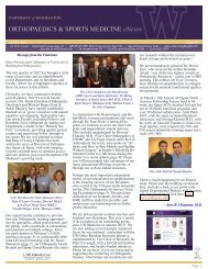
Figure 1: Balance stability angles. a) Consider a glenoid that has a centerline “C” perpendicular to<br />
the surface at the center <strong>of</strong> the glenoid <strong>and</strong> that has a radius <strong>of</strong> curvature “R” as well as a width “W”<br />
in a specified direction from center to edge. b) Consider an unattached humeral head component<br />
articulating with this glenoid for which the sum <strong>of</strong> all forces acting on it is F, the net humeral joint<br />
reaction force. The vector F makes an angle with the centerline, C, <strong>of</strong> Ø. If the humeral head is free<br />
to move under the influence <strong>of</strong> gravity, F becomes the gravitational force vector <strong>and</strong> is always vertical.<br />
By tipping the glenoid, Ø can be progressively increased. c) As Ø is increased, it reaches a value at<br />
which the humeral head dislocates over the edge <strong>of</strong> the glenoid. This value for Ø is known as the<br />
balance stability angle, or BSA. If R <strong>and</strong> W are known, Ø can be predicted from sine Ø = W/R, or Ø =<br />
arc sine W/R.<br />
Figure 2: The glenoidogram. a) The glenoidogram in a given direction is the path traced by the humeral<br />
head as it travels across the glenoid surface in the direction <strong>of</strong> interest. b) The width (W) <strong>and</strong> depth (D)<br />
<strong>of</strong> the effective concavity can be seen on the glenoidogram. The maximal slope <strong>of</strong> the glenoidogram<br />
(S) is the tangent <strong>of</strong> the balance stability angle. [Matsen, 1994 #7][PEMS, R <strong>and</strong> M chapter on stability].<br />
METHODS<br />
The intrinsic stability provided by<br />
the glenoid in a given direction can be<br />
characterized by the maximal angle the<br />
humeral joint reaction force can make<br />
with the glenoid centerline before the<br />
humeral head dislocates; this quantity<br />
is defined as the balance stability angle<br />
(BSA) in the specified direction (Figure<br />
1). The BSA can be calculated by<br />
analysis <strong>of</strong> the shape <strong>of</strong> the glenoid<br />
surface (Figure 2). The BSA can also be<br />
measured directly by placing an<br />
unconstrained humeral head loaded<br />
only by gravity within the glenoid<br />
oriented with the centerline vertical <strong>and</strong><br />
then tipping the glenoid until the<br />
humeral head dislocates (Figure 1). In<br />
this study, the balance stability angles<br />
were both calculated <strong>and</strong> measured in<br />
8 different directions for 3 unused<br />
polyethylene glenoid components <strong>and</strong><br />
11 cadaveric glenoids in 4 different<br />
states: 1) native without capsule or<br />
rotator cuff, 2) denuded <strong>of</strong> cartilage <strong>and</strong><br />
labrum, 3) after reaming the glenoid<br />
surface around the glenoid centerline<br />
using a spherical reamer with a radius<br />
<strong>of</strong> 25.0 millimeters, <strong>and</strong> 4) after<br />
reaming around the glenoid centerline<br />
using a spherical reamer with a radius<br />
<strong>of</strong> 22.5 millimeters (Figure 3). We also<br />
attempted to predict the BSAs<br />
achievable with reaming to each <strong>of</strong> the<br />
two different radii from measurement<br />
<strong>of</strong> the width <strong>of</strong> the glenoid before it was<br />
reamed.<br />
RESULTS<br />
Denuding the glenoids <strong>of</strong> their<br />
articular cartilage reduced the intrinsic<br />
stability, especially in the posterior<br />
direction (Figure 4 <strong>and</strong> Table 1).<br />
Reaming the glenoid restored the<br />
intrinsic stability back to values<br />
comparable to those <strong>of</strong> the normal<br />
glenoid. For example, the average<br />
calculated BSA in the posterior<br />
direction for all eleven glenoids was:<br />
native = 24°± 9°, denuded = 14°± 6°,<br />
reamed to radius 25.0 millimeter = 25°<br />
± 5°, reamed to radius 22.5 millimeter<br />
= 33° ± 6°. The BSAs for the<br />
<strong>2002</strong> ORTHOPAEDIC RESEARCH REPORT 53