BELTS AND PULLEYS - Pic-designcatalog.com
BELTS AND PULLEYS - Pic-designcatalog.com
BELTS AND PULLEYS - Pic-designcatalog.com

You also want an ePaper? Increase the reach of your titles
YUMPU automatically turns print PDFs into web optimized ePapers that Google loves.
DESIGN<br />
R<br />
<strong>BELTS</strong> <strong>AND</strong> <strong>PULLEYS</strong><br />
R<br />
RECISION<br />
NDUSTRIAL<br />
OMPONENTS<br />
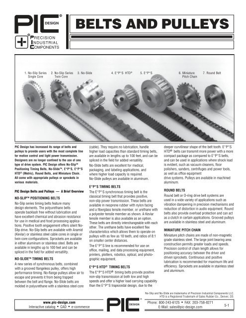
1. No-Slip Series 2. No-Slip Series 3. No-Slide 4. E*P*S HTD ® 5. E*P*S 6. Miniature 7. Round Belt<br />
1. Single Core 2. Twin Core Pitch Chain<br />
PIC Design has increased its range of belts and<br />
pulleys to provide users with the most <strong>com</strong>plete line<br />
for motion control and light power transmission.<br />
Designers are no longer confined to the use of one<br />
type of drive system. PIC Design offers No-Slip TM<br />
Positioning Timing Belts, No-Slide TM , E*P*S, E*P*S<br />
HTD ® (Metric), Round Belts, and Miniature Chain.<br />
All <strong>com</strong>e with appropriate pulleys or sprockets in<br />
various materials.<br />
PIC Design Belts and Pulleys — A Brief Overview<br />
NO-SLIP TM POSITIONING <strong>BELTS</strong><br />
No-Slip series timing belts feature many<br />
design elements. The polyurethane belts<br />
operate backlash free without lubrication and<br />
have excellent chemical and abrasion resistance<br />
for use in medical and food processing applications.<br />
Positive tooth engagement offers silent No-<br />
Slip drive. No-Slip belts are available with Aramid<br />
(Kevlar) or stainless steel cable cores in single or<br />
twin core configurations. Sprockets are available<br />
in either aluminum or stainless steel. Belts are<br />
available in lengths up to 100 feet and can be<br />
spliced in the field for added versatility.<br />
NO-SLIDE TM TIMING <strong>BELTS</strong><br />
A new series of synchronous belts, <strong>com</strong>bined<br />
with a grooved flangeless pulley, offers high<br />
performance timing. No-flange pulleys allow air to<br />
escape and prevents it from being trapped<br />
between the belt and flange. No-Slide belts are<br />
molded in polyurethane with a stainless steel core<br />
(cable). They require no lubrication, handle<br />
higher load capacities than standard timing belts,<br />
are available in lengths up to 100 feet, and can be<br />
spliced in the field for added versatility.<br />
No-Slide belts are excellent for medical,<br />
packaging, and labeling applications, and<br />
where higher load capacity is required.<br />
No-Slide pulleys are available in aluminum.<br />
E*P*S TIMING <strong>BELTS</strong><br />
The E*P*S synchronous timing belt is the<br />
classical timing belt that provides positive,<br />
non-slip power transmission. These belts are<br />
available in neoprene rubber with nylon facing<br />
and a fiberglass tensile member, or urethane with<br />
a polyester tensile member as shown. A Kevlar<br />
tensile member is also available as an option.<br />
These belts are directly interchangeable with each<br />
other. The urethane belts have excellent flex<br />
characteristics which allows them to operate on<br />
pulleys with as few as 10 teeth, and ratios of 8:1<br />
on smaller center distances.<br />
The E*P*S line is re<strong>com</strong>mended for use on<br />
office, mailing, and data processing equipment,<br />
printers, plotters, robotics, optical, and photographic<br />
equipment.<br />
E*P*S HTD ® TIMING <strong>BELTS</strong><br />
The E*P*S HTD ® timing belts provide positive<br />
non-slip transmission at both low and high<br />
speeds and offer a higher load carrying capability<br />
than the E*P*S trapezoidal design, due to the<br />
deeper curvilinear shape of the belt tooth. E*P*S<br />
HTD ® belts can transmit more power with a more<br />
<strong>com</strong>pact package as <strong>com</strong>pared to E*P*S belts,<br />
and can be used in applications where shock load<br />
is evident, such as vacuum cleaners, floor<br />
polishers, sanders, centrifuges and power tools,<br />
as well as office equipment<br />
drive systems. Pulleys are available in machined<br />
aluminum.<br />
ROUND <strong>BELTS</strong><br />
Round belt or O-ring drive belt systems are<br />
used in a wide variety of applications such as<br />
vibration dampening in precision mechanisms and<br />
reduction of distortion in audio equipment. Round<br />
belts also provide overload protection and can act<br />
as a clutch in certain applications. Grooved pulleys<br />
are available in stainless steel and aluminum.<br />
MINIATURE PITCH CHAIN<br />
Miniature pitch chains are made of non-magnetic<br />
grade stainless steel. The large joint bearing area<br />
construction permits greater loads and speeds.<br />
Precision control of chain length allows for<br />
positioning accuracy between the driver and<br />
driven sprockets. Continuous and positive<br />
lubrication is re<strong>com</strong>mended for maximum life and<br />
efficiency. Sprockets are available in stainless steel<br />
and aluminum.<br />
www.pic-design.<strong>com</strong><br />
Interactive catalog ■ CAD ■ e-<strong>com</strong>merce<br />
DESIGN<br />
®<br />
No-Slip and No-Slide are trademarks of Precision Industrial Components LLC.<br />
HTD is a Registered Trademark of Gates Rubber Co., Denver, CO.<br />
Phone: 800-243-6125 ■ FAX: 203-758-8271<br />
E-Mail: sales@pic-design.<strong>com</strong><br />
5-1
TECHNICAL SECTION<br />
Application Information<br />
To assist customers in selecting the most appropriate flexible drive<br />
system in particular applications, PIC Design has included an Application<br />
Guide along with a Flexible Drive System Comparison Chart.<br />
The Application Guide assists in determining the drive system suitable for<br />
your application. If your specific applications are not listed, use ones which<br />
are most similar.<br />
The Comparison Chart will enable users to choose the drive system that will<br />
best suit a particular application. The features of these drive systems are<br />
listed so that the drive system selected will provide the most economical,<br />
maintenance-free and longest life for a particular application.<br />
No-Slip Series belts fulfill the need for the most accurate and smoothest<br />
running drive system, while the E*P*S Series provides an economical<br />
solution to positive power transmission. No-Slide timing belts offer higher<br />
load capacities, run on no-flange pulleys, offer quiet operation, and can be<br />
used in smaller areas. Miniature chains offer a positive drive system for<br />
heavier duty applications, while Round Belts are most suitable for low-load<br />
applications not requiring positioning accuracy.<br />
Users are encouraged to request advise or answers to questions not covered<br />
here — please don’t hesitate to consult PIC Design directly.<br />
Application Guide<br />
Flexible Drive Systems<br />
No-Slip No-Slide Timing<br />
Chain<br />
Belts Belts Belts<br />
CNC Positioning Devices X X X<br />
Magnification & Focusing<br />
Adjustment Devices<br />
X<br />
Laser Alignment Mechanisms<br />
Gear Boxes X X X X<br />
X<br />
Paper Feeds X X X<br />
Household Appliances X X X<br />
Centrifuges X X<br />
Encoders — High Resolution<br />
X<br />
Std. Resolution X X X<br />
Plotters<br />
X<br />
Plating Room Equipment X X X X<br />
Round<br />
High Speed Printers X X<br />
Manual Positioning Mechanisms X X X X X<br />
Power Tools, Sanders, etc. X X<br />
Machinery Drives X X X X<br />
Advertising Displays X X X X X<br />
Stepper Motor Drives X X X<br />
Business Machines X X X X X<br />
Audio & Visual Equipment X X X X X<br />
Flexible Drive System Feature Comparison<br />
Drive Type No-Slip No-Slide E*P*S (Timing) E*P*S HTD ® Chain Round<br />
F, F32 - 32DP, F8B-40DP (.0816CP), EPS-A-.080CP, EPS-A-.080CP, AF2-1/16" Thick<br />
Catalog Series F24C - .1309CP, F20B-.200CP, EPS-D-.200CP, EPS-D-.200CP, EPS-F-3mm, EL-.1475CP AF3-3/32" Thick<br />
and Pitch FR - .1475CP, F37B-.375CP, EPS-J-.375CP, EPS-C-.0816CP EPS-G-5mm EL25-.250CP AF4-1/8 " Thick<br />
FL, FM, F20TS - 20DP, (40DP) AF5-3/16" Thick<br />
F25C - .250CP<br />
AF6-1/4 " Thick<br />
Body Material Polyurethane Polyurethane Neoprene Polyurethane Neoprene Stainless Steel Polyurethane<br />
Reinforcement<br />
Drive Both<br />
Sides of Belt<br />
Stainless Steel<br />
or Aramid Fiber<br />
Stainless Steel<br />
or Aramid Fiber<br />
Fiber Glass Polyester Fiber Fiber Glass — None<br />
Yes 1 No No No No Yes Yes<br />
Right Angle Drive FS & FA 2 No No No No No Yes<br />
Resistance to Oils Stainless Steel - Stainless Steel -<br />
and Chemicals Excellent Excellent Good No No No Yes<br />
Aramid - Good Aramid - Good<br />
Single Core —<br />
Pulley to Pulley 3 up to 5 O Up to 1/10 O Up to 1/4 O Up to 1/4 O Up to 1/4 O No Yes<br />
Misalignment Double Core —<br />
up to 1/10 O<br />
32DP — Involute<br />
Pulley Tooth Form 20DP, 24DP, Trapezoidal Trapezoidal Trapezoidal HTD ® Curvilinear Precision Sprocket Radius Groove<br />
.1475CP, .250CP —<br />
Precision Sprocket<br />
Abrasion Resistance Excellent Excellent Good Excellent Good Good Excellent<br />
32DP — Yes<br />
Pulleys Mesh With 20DP, 24DP —<br />
No No No No No No<br />
Standard Spur Gears Option Available<br />
.1475CP, .250CP — No<br />
Ability to Withstand<br />
Fair Fair Limited Good Fair Limited Excellent<br />
Shock Loads<br />
Temperature ( o F) -65 to +180 4 -65 to +180 4 -30 to +185 -65 to +180 -30 to +185 — -40 to +180<br />
Notes:<br />
Note 1<br />
Note 2<br />
Driving stainless steel reinforced belts on both sides, results in a<br />
reduction of belt life due to reverse bending.<br />
Twisting of the belt may cause the belt to wear excessively and<br />
reduce belt life. Shafts at right angles require a center distance at<br />
least 5 1/2 times the larger pully diameter.<br />
Note 3 Misalignment of pulleys will cause abrasive wear on the belt and reduce belt life.<br />
Note 4 Practical operating temperatures are -10 o F to +140 o F.<br />
5-2<br />
Phone: 800-243-6125 ■ FAX: 203-758-8271<br />
E-Mail: sales@pic-design.<strong>com</strong><br />
DESIGN<br />
®<br />
www.pic-design.<strong>com</strong><br />
Interactive catalog ■ CAD ■ e-<strong>com</strong>merce
NO-SLIP <strong>AND</strong> NO-SLIDE DRIVE SYSTEMS<br />
PIC Design Guide For No-Slip and No-Slide Drive Systems<br />
Reinforcement Re<strong>com</strong>mended Re<strong>com</strong>mended Re<strong>com</strong>mended Re<strong>com</strong>mended Ultimate Static<br />
No-Slip / Catalog Belt Cable Diameter Positional Minimum Pulley Minimum Maximum Belt Maximum Tensile Strength<br />
No-Slide Series Pitch (Inch) Accuracy Diameter Number Of Teeth Operating Speed Operating Belt For Endless Belt<br />
(Inch) In Mesh (No Load / Load) Tension (LBS) (LBS)<br />
(Feet per Min.)<br />
No-Slip<br />
No-Slide<br />
FA<br />
FS<br />
F32BS18<br />
F32CS<br />
FLA<br />
FLS<br />
FMA<br />
FMS<br />
F20TS<br />
FRA<br />
FRS<br />
F24CA<br />
F24CS<br />
F25CA<br />
F25CS<br />
F8BS<br />
F20BA<br />
F20BS<br />
F37BS<br />
32DP<br />
.0982CP<br />
Single<br />
Core<br />
32DP / .0982CP<br />
Double Core<br />
20DP<br />
.15708CP<br />
Single<br />
Core<br />
20DP<br />
.15708CP<br />
Double<br />
Core<br />
.032<br />
Aramid Fiber<br />
.032<br />
Stainless Steel<br />
.018<br />
Stainless Steel<br />
.018<br />
Stainless Steel<br />
.032<br />
Aramid Fiber<br />
.032<br />
Stainless Steel<br />
.032<br />
Aramid Fiber<br />
.032<br />
Stainless Steel<br />
20DP .032<br />
Triple Core Stainless Steel<br />
.1475CP<br />
Double<br />
Core<br />
24DP<br />
.1309CP<br />
Double<br />
Core<br />
.250CP<br />
Double<br />
Core<br />
.032<br />
Aramid Fiber<br />
.032<br />
Stainless Steel<br />
.032<br />
Aramid Fiber<br />
.032<br />
Stainless Steel<br />
.032<br />
Aramid Fiber<br />
.032<br />
Stainless Steel<br />
40DP, .0816CP .018<br />
Single Core Stainless Steel<br />
.200CP<br />
Single<br />
Core<br />
.032<br />
Aramid Fiber<br />
.032<br />
Stainless Steel<br />
.375CP .047<br />
Single Core Stainless Steel<br />
Excellent<br />
Very Good<br />
Good<br />
Good<br />
.500 8 900 / 300 4-5 25<br />
.750 8 900 / 350 6-8 50<br />
.500 8 800 / 350 4-5 20<br />
.750 8 850 / 350 6-7 50<br />
.750 6 1100 / 500 5-6 25<br />
.750 6 1100 / 600 10-12 50<br />
.750 6 1300 / 550 10-12 50<br />
.750 6 1300 / 700 20-25 100<br />
Good .750 6 1300 / 700 20-25 100<br />
Good<br />
Good<br />
Good<br />
.750 6 1300 / 550 10-12 50<br />
.750 6 1300 / 700 20-25 100<br />
.750 6 1300 / 550 10-12 50<br />
.750 6 1300 / 700 20-25 100<br />
.750 5 1300 / 550 10-12 50<br />
.750 5 1300 / 700 20-25 100<br />
Good .500 8 700 / 300 4-5 20<br />
Very Good<br />
.750 6 1200 / 550 5-6 25<br />
.750 6 1200 / 650 10-12 50<br />
Good 1.375 6 800 / 450 25-30 125<br />
BELT TENSIONER<br />
TE-1<br />
Material: Shaft 303 Stainless Steel<br />
Housing Aluminum Black Anodized<br />
Features: Easily adjusted by pivoting tensioner<br />
about mounting surface<br />
Part Number: TE-1<br />
1.0 ±30°<br />
adjustment<br />
1.75<br />
Counterbore for 2x 8-32 socket<br />
head cap screws on .50 centers<br />
(not supplied)<br />
2.5<br />
3/4<br />
#8-32 locking<br />
screw<br />
3/4<br />
3/8<br />
.750<br />
.250 shaft dia.<br />
.50 Min<br />
Shielded ball<br />
bearings (2)<br />
www.pic-design.<strong>com</strong><br />
Interactive catalog ■ CAD ■ e-<strong>com</strong>merce<br />
DESIGN<br />
®<br />
Phone: 800-243-6125 ■ FAX: 203-758-8271<br />
E-Mail: sales@pic-design.<strong>com</strong><br />
5-3
NO-SLIP SERIES<br />
PIC’s No-Slip and No-Slide High Performance<br />
Positioning Drive Systems<br />
The No-Slip principle was introduced by PIC over 25 years ago. The No-<br />
Slip principle allows the drive system to function primarily as a precise<br />
positioning device by locating the drive pins on the belt pitch line,<br />
allowing them to mesh smoothly with the pulleys without the clearance<br />
required for standard belts and pulleys. The elimination of the clearance<br />
makes the drive system “backlash free” and an excellent means of<br />
maintaining the accuracy for precision positioning applications.<br />
No-Slip belts utilize round drive pins which are molded perpendicularly to<br />
one or more molded tensile members. These molded tensile members are<br />
larger than the drive pins, which are located on the pitch line of the<br />
tensile member. The molded tensile member(s) surround a reinforcing<br />
cable(s) providing strength and minimal stretch while the loads are<br />
transferred through the tensile members to the pulley shoulders or<br />
grooves.<br />
The 32DP (diametral pitch) No-Slip drive system is an industry standard.<br />
The single core belt runs on pulleys that are generated with precision<br />
involute form teeth. This fine pitch results in a greater number of teeth<br />
engaged, which produces the highest positioning accuracy for applications<br />
such as encoders and measuring devices. The involute form of the<br />
pulleys allows a spur gear to be driven by the belt or pulley. The 32DP<br />
twin core design No-Slip drive system offers additional strength for<br />
higher loads.<br />
The .1475CP and .2500 CP No-Slip drive systems are twin core belts that<br />
are an economical solution to miniature pitch stainless steel chain. These<br />
belts are for high load carrying applications requiring No-Slip accuracy.<br />
These belts have replaced miniature pitch stainless steel chain in many<br />
existing applications.<br />
The No-Slide principle allows the drive system to operate using pulleys<br />
without flanges. The belt stays on the center of the pulley due to an<br />
encapsulated stainless steel or Aramid cable in the center of the belt and<br />
a matching groove in the pulley.<br />
The elimination of a flange results in two major benefits. It produces a<br />
more <strong>com</strong>pact drive system and it also eliminates the air trapped by the<br />
flanges found on conventional synchronous belts — therefore making it<br />
a quieter running belt.<br />
No-Slide belts are produced by a continuous polyurethane molding<br />
process with either a stainless steel or Aramid core. The finished belt is<br />
joined by crimping the cable ends within a stainless steel ferrule, which is<br />
then overmolded for added strength and protection of the pulley.<br />
These polyurethane belts have inherent chemical and abrasion resistance<br />
that allow operation in applications where carbon dusting encountered<br />
with neoprene belts cannot be tolerated. The No-Slide series of belts are<br />
excellent for medical and packaging applications.<br />
BELT LENGTH CALCULATIONS<br />
D = Pitch Diameter Large Pulley (inches)<br />
d = Pitch Diameter Small Pulley (inches)<br />
C = Center Distance (inches)<br />
α = sin<br />
[ D-d 2C ]<br />
-1<br />
BELT SPEED CALCULATIONS<br />
BS(fpm) = (.262) x PD x RPM<br />
ST<strong>AND</strong>ARD CALCULATIONS<br />
α = Angle Between Belt and Centerline<br />
L = Belt Pitch Length (inches — approx.)<br />
L = π (D + d) + 4C 2 +D 2 +d 2<br />
2<br />
CENTER DISTANCE CALCULATIONS<br />
C = K + K2 - 32 (D-d) 2<br />
16<br />
Where K = 4L - 2 π (D+d)<br />
Required Given Formula<br />
Shaft speeds (rpm) R =<br />
Speed ratio (R) Pulley Diameters (D & d) R =<br />
Horsepower (hp)<br />
For Parallel Shafts:<br />
L = 2C Cos α + π (D+d) πα (D-d)<br />
+<br />
2 180<br />
or<br />
L APPROX = 2C + 1.57(D+d) + (D-d)2<br />
4C<br />
Torque (T) in in.- lbs.<br />
Effective tension (Te)<br />
Number of pulley<br />
grooves (N & n)<br />
R =<br />
Torque (T) in in.- lbs.<br />
hp = T x rpm<br />
Shaft speed (rpm) 63,025<br />
Shaft horsepower (hp)<br />
Shaft speed (rpm)<br />
Shaft horsepower (hp)<br />
Belt speed (BS)<br />
For Right Angle Shafts<br />
FA & FS Only:<br />
T =<br />
rpm (faster shaft speed)<br />
rpm (slower shaft speed)<br />
D (larger pulley diameter)<br />
d (smaller pulley diameter)<br />
N (larger pulley groove no.)<br />
n (smaller pulley groove no.)<br />
63,025 x hp<br />
rpm<br />
33,000 x hp<br />
Te =<br />
BS<br />
Effective tension (Te) Torque (T) in in.- lbs.<br />
Te = 2 x T<br />
in pounds Pulley pd in inches pd<br />
The design guide (shown on previous page) enables users to select the<br />
appropriate system for a particular application. The belt length calculations<br />
are included to insure that the proper belt length has been selected<br />
for the center distance and ratio of your drive system.<br />
5-4<br />
Phone: 800-243-6125 ■ FAX: 203-758-8271<br />
E-Mail: sales@pic-design.<strong>com</strong><br />
DESIGN<br />
®<br />
www.pic-design.<strong>com</strong><br />
Interactive catalog ■ CAD ■ e-<strong>com</strong>merce
BELT SPLICING KIT<br />
Belt splicing in the field is possible for NO-SLIP & NO-SLIDE positioning<br />
and timing belts when the appropriate splicing kit is used. Part numbers<br />
for these kits can be found on each No-Slip — No-Slide belt specification<br />
page or in the table below. In addition to containing a crimp tool & die<br />
set, positioning holddown rack and cable cutter; detailed procedures<br />
define the five basic steps to assure a correct splice. These steps are:<br />
1. Cut belt to desired length<br />
2. Remove polyurethane from each end<br />
3. Insert ends into ferrule<br />
4. Position belt into holddown feature<br />
5. Crimp<br />
When extra ferrules are required they may be ordered as follows:<br />
Cable Size<br />
Ferrule Part Number<br />
.018" Diameter FER018<br />
.032" Diameter FER032<br />
.047" Diameter FER047<br />
Note: Because factory crimps use highly controlled pneumatic equipment and,<br />
in some cases polyurethane overmolding, field crimps result in loads<br />
that are 50% of the catalog ratings.<br />
Field Belt Splicing Kit<br />
Belt Kit Crimp Crimp Die Hobby Stripper Ferrules* Position Rack **Flush**<br />
Series Part Plier Die Knife Cutter Part & Hold Down Cutter<br />
Number Number Part Number Part Number Part Number Part Number Number Part Number Part Number<br />
FS / FA F-SK TL-91 TL-89 TL-86 TL-87 FER032 TL-70-71 —<br />
FLS / FLA FL-SK TL-91 TL-89 TL-86 TL-87 FER032 TL-76-77 —<br />
FMS / FMA FM-SK TL-91 TL-89 TL-86 TL-87 FER032 TL-78-79 —<br />
FRS / FRA FR-SK TL-91 TL-89 TL-86 TL-87 FER032 TL-80-81 —<br />
F8BS F8B-SK TL-91 TL-90 TL-86 TL-87 FER018 TL-62-63 —<br />
F20BS / F20BA F20B-SK TL-91 TL-89 TL-86 TL-87 FER032 TL-60-61 TL-32<br />
F20TS F20T-SK TL-91 TL-89 TL-86 TL-87 FER032 TL-66-67 —<br />
F24CS / F24CA F24C-SK TL-91 TL-89 TL-86 TL-87 FER032 TL-72-73 —<br />
F25CS F25C-SK TL-91 TL-89 TL-86 TL-87 FER032 TL-74-75 TL-32<br />
F32BS18 F32B18-SK TL-91 TL-90 TL-86 TL-87 FER018 TL-70-71 —<br />
F32CS / F32CA F32C-SK TL-91 TL-90 TL-86 TL-87 FER018 TL-68-69 —<br />
F37BS F37B-SK TL-91 TL-88 TL-86 TL-87 FER047 TL-64-65 TL-32<br />
Notes:<br />
* Twenty (20) ferrules included in each kit.<br />
** Heavy duty cutter supplied as indicated - can be ordered as option for other kits.<br />
www.pic-design.<strong>com</strong><br />
Interactive catalog ■ CAD ■ e-<strong>com</strong>merce<br />
DESIGN<br />
®<br />
Phone: 800-243-6125 ■ FAX: 203-758-8271<br />
E-Mail: sales@pic-design.<strong>com</strong><br />
5-5
NO-SLIP POSITIVE DRIVE BELT - ULTRA PRECISION<br />
32DP, .0982CP — Single Core<br />
Continuous body runs on<br />
involute form pulleys for highest<br />
accuracy and smoothest motion.<br />
Material:<br />
FA Series: Molded Polyurethane, .032" diameter Aramid Fiber Core (Kevlar). Color: Blue<br />
FS Series: Molded Polyurethane, .032" diameter Stainless Steel Core. Color: Blue<br />
Number of Length Part No. Part No.<br />
Drive Pins (Ref.) Aramid Core Steel Core<br />
64 6.283 FA-64 FS-64<br />
80 7.854 FA-80 FS-80<br />
95 9.327 FA-95 FS-95<br />
112 10.996 FA-112 FS-112<br />
126 12.370 FA-126 FS-126<br />
128 12.566 FA-128 FS-128<br />
144 14.137 FA-144 FS-144<br />
158 15.512 FA-158 FS-158<br />
176 17.279 FA-176 FS-176<br />
189 18.557 FA-189 FS-189<br />
208 20.420 FA-208 FS-208<br />
220 21.598 FA-220 FS-220<br />
240 23.562 FA-240 FS-240<br />
252 24.740 FA-252 FS-252<br />
272 26.704 FA-272 FS-272<br />
283 27.784 FA-283 FS-283<br />
304 29.845 FA-304 FS-304<br />
315 30.923 FA-315 FS-315<br />
336 32.987 FA-336 FS-336<br />
346 33.967 FA-346 FS-346<br />
368 36.128 FA-368 FS-368<br />
377 37.011 FA-377 FS-377<br />
400 39.270 FA-400 FS-400<br />
408 40.055 FA-408 FS-408<br />
432 42.412 FA-432 FS-432<br />
For other length belts longer than the minimum listed, substitute the desired number of<br />
drive pins at the end of the part number.<br />
Number of Length Part No. Part No.<br />
Drive Pins (Ref.) Aramid Core Steel Core<br />
440 43.197 FA-440 FS-440<br />
464 45.553 FA-464 FS-464<br />
471 46.238 FA-471 FS-471<br />
480 47.124 FA-480 FS-480<br />
496 48.695 FA-496 FS-496<br />
512 50.265 FA-512 FS-512<br />
528 51.836 FA-528 FS-528<br />
544 53.407 FA-544 FS-544<br />
560 54.978 FA-560 FS-560<br />
576 56.549 FA-576 FS-576<br />
592 58.120 FA-592 FS-592<br />
608 59.690 FA-608 FS-608<br />
624 61.261 FA-624 FS-624<br />
640 62.832 FA-640 FS-640<br />
656 64.402 FA-656 FS-656<br />
672 65.973 FA-672 FS-672<br />
688 67.544 FA-688 FS-688<br />
704 69.115 FA-704 FS-704<br />
720 70.686 FA-720 FS-720<br />
736 72.257 FA-736 FS-736<br />
752 73.827 FA-752 FS-752<br />
768 75.398 FA-768 FS-768<br />
784 76.969 FA-784 FS-784<br />
800 78.540 FA-800 FS-800<br />
— — — —<br />
Bulk Lengths — Not Spliced<br />
Length<br />
Aramid Core<br />
Part Number<br />
Steel Core<br />
Part Number<br />
5 Ft FA-5FT FS-5FT<br />
10 Ft FA-10FT FS-10FT<br />
25 Ft FA-25FT FS-25FT<br />
50 Ft FA-50FT FS-50FT<br />
For field splicing use Kit F-SK.<br />
See page 5-5.<br />
32DP (.0982 CP) ORIGINAL SINGLE CORE<br />
NO-SLIP <strong>BELTS</strong> — SERIES FA & FS<br />
Smoothest motion, highest accuracy.<br />
Continuous molded body runs on precision,<br />
involute form pulleys. Fine pitch results in<br />
greatest number of teeth engaged. Single core<br />
permits non-parallel or right angle shafts<br />
position. Re<strong>com</strong>mended for highest accuracy,<br />
lower load applications such as encoders and<br />
measuring devices.<br />
INCREASED FLEXIBILITY OPTION<br />
For those applications requiring the greatest<br />
flexibility at a reduced load, PIC Design has<br />
this belt available with a .018" diameter<br />
stainless steel core. The part number is<br />
F32BS18- . Where is the<br />
number of drive pins. Example: Part Number<br />
for 144 drive pins is F32BS18-144.<br />
Bulk Lengths — Not Spliced<br />
Length<br />
Steel Core<br />
Part Number<br />
5 Ft F32BS18-5FT<br />
10 Ft F32BS18-10FT<br />
25 Ft F32BS18-25FT<br />
50 Ft F32BS18-50FT<br />
For field splicing use Kit F-SK.<br />
See page 5-5.<br />
5-6<br />
Phone: 800-243-6125 ■ FAX: 203-758-8271<br />
E-Mail: sales@pic-design.<strong>com</strong><br />
DESIGN<br />
®<br />
www.pic-design.<strong>com</strong><br />
Interactive catalog ■ CAD ■ e-<strong>com</strong>merce
NO-SLIP <strong>PULLEYS</strong><br />
32DP, .0982CP — For FA, FS & F32BS18 No-Slip Single Core Drive Belts<br />
PIN HUB<br />
Bore<br />
Dimen.<br />
1/8 3/16 1/4 4 mm 6 mm<br />
A .1248 .1873 .2498 .1573 .2360<br />
B .312 .375 .500 .375 .500<br />
C .09 .11 .12 .11 .12<br />
D .375 .406 .437 .406 .437<br />
Set<br />
Screw<br />
#2-56 #4-40 #6-32 M2 x .4 M3 x .5<br />
Material: 303 Stainless Steel<br />
2024-T4 Aluminum (Anodized before cutting)<br />
Geared Pulley Data Stainless Steel Bore Size / Part Number Aluminum Bore Size / Part Number<br />
No. Teeth P.D. O.D. .1248 .1873 .2498 4mm 6mm .1248 .1873 .2498 4mm 6mm<br />
14 * .4375 .500 FC1-14 — — — — FC2-14 — — — —<br />
15 * .4687 .531 FC1-15 FC3-15 — MGP1-15 — FC2-15 FC4-15 — MGP2-15 —<br />
16 .5000 .563 FC1-16 FC3-16 — MGP1-16 — FC2-16 FC4-16 — MGP2-16 —<br />
18 .5625 .625 FC1-18 FC3-18 — MGP1-18 — FC2-18 FC4-18 — MGP2-18 —<br />
20 .6250 .688 FC1-20 FC3-20 FC5-20 MGP1-20 MGP3-20 FC2-20 FC4-20 FC6-20 MGP2-20 MGP4-20<br />
22 .6875 .750 FC1-22 FC3-22 FC5-22 MGP1-22 MGP3-22 FC2-22 FC4-22 FC6-22 MGP2-22 MGP4-22<br />
24 .7500 .813 FC1-24 FC3-24 FC5-24 MGP1-24 MGP3-24 FC2-24 FC4-24 FC6-24 MGP2-24 MGP4-24<br />
26 .8125 .875 FC1-26 FC3-26 FC5-26 MGP1-26 MGP3-26 FC2-26 FC4-26 FC6-26 MGP2-26 MGP4-26<br />
28 .8750 .938 FC1-28 FC3-28 FC5-28 MGP1-28 MGP3-28 FC2-28 FC4-28 FC6-28 MGP2-28 MGP4-28<br />
30 .9375 1.000 FC1-30 FC3-30 FC5-30 MGP1-30 MGP3-30 FC2-30 FC4-30 FC6-30 MGP2-30 MGP4-30<br />
32 1.0000 1.063 FC1-32 FC3-32 FC5-32 MGP1-32 MGP3-32 FC2-32 FC4-32 FC6-32 MGP2-32 MGP4-32<br />
36 1.1250 1.188 FC1-36 FC3-36 FC5-36 MGP1-36 MGP3-36 FC2-36 FC4-36 FC6-36 MGP2-36 MGP4-36<br />
40 1.2500 1.313 FC1-40 FC3-40 FC5-40 MGP1-40 MGP3-40 FC2-40 FC4-40 FC6-40 MGP2-40 MGP4-40<br />
48 1.5000 1.563 FC1-48 FC3-48 FC5-48 MGP1-48 MGP3-48 FC2-48 FC4-48 FC6-48 MGP2-48 MGP4-48<br />
56 1.7500 1.813 FC1-56 FC3-56 FC5-56 MGP1-56 MGP3-56 FC2-56 FC4-56 FC6-56 MGP2-56 MGP4-56<br />
64 2.0000 2.063 FC1-64 FC3-64 FC5-64 MGP1-64 MGP3-64 FC2-64 FC4-64 FC6-64 MGP2-64 MGP4-64<br />
72 2.2500 2.313 FC1-72 FC3-72 FC5-72 MGP1-72 MGP3-72 FC2-72 FC4-72 FC6-72 MGP2-72 MGP4-72<br />
80 2.5000 2.563 — FC3-80 FC5-80 MGP1-80 MGP3-80 — FC4-80 FC6-80 MGP2-80 MGP4-80<br />
88 2.7500 2.813 — FC3-88 FC5-88 MGP1-88 MGP3-88 — FC4-88 FC6-88 MGP2-88 MGP4-88<br />
96 3.0000 3.063 — FC3-96 FC5-96 MGP1-96 MGP3-96 — FC4-96 FC6-96 MGP2-96 MGP4-96<br />
112 3.5000 3.563 — FC3-112 FC5-112 MGP1-112 MGP3-112 — FC4-112 FC6-112 MGP2-112 MGP4-112<br />
128 4.0000 4.063 — FC3-128 FC5-128 MGP1-128 MGP3-128 — FC4-128 FC6-128 MGP2-128 MGP4-128<br />
* Re<strong>com</strong>mended for use as an idler only<br />
See Note Below.<br />
Stainless<br />
SPLIT HUB<br />
Note:<br />
Other Size Bores Available, Consult Factory.<br />
For unlisted number of teeth, specify the number of teeth desired as the last figure in the part number.<br />
EXAMPLE: For a 52-tooth stainless steel pulley, specify Part Number: FD5-52.<br />
For number of teeth above or below listed sizes, consult factory.<br />
www.pic-design.<strong>com</strong><br />
Interactive catalog ■ CAD ■ e-<strong>com</strong>merce<br />
DESIGN<br />
®<br />
Pully Data<br />
Steel Aluminum<br />
No.<br />
P.D. O.D.<br />
.2498 Bore .2498 Bore<br />
Teeth<br />
Part No. Part No.<br />
14 * .4375 .500 FD5-14 FD6-14<br />
15 * .4687 .531 FD5-15 FD6-15<br />
16 .5000 .563 FD5-16 FD6-16<br />
18 .5625 .625 FD5-18 FD6-18<br />
20 .6250 .688 FD5-20 FD6-20<br />
22 .6875 .750 FD5-22 FD6-22<br />
24 .7500 .813 FD5-24 FD6-24<br />
26 .8125 .875 FD5-26 FD6-26<br />
28 .8750 .938 FD5-28 FD6-28<br />
30 .9375 1.000 FD5-30 FD6-30<br />
32 1.0000 1.063 FD5-32 FD6-32<br />
36 1.1250 1.188 FD5-36 FD6-36<br />
40 1.2500 1.313 FD5-40 FD6-40<br />
48 1.5000 1.563 FD5-48 FD6-48<br />
56 1.7500 1.813 FD5-56 FD6-56<br />
64 2.0000 2.063 FD5-64 FD6-64<br />
72 2.2500 2.313 FD5-72 FD6-72<br />
* Re<strong>com</strong>mended for use as an idler only<br />
Phone: 800-243-6125 ■ FAX: 203-758-8271<br />
E-Mail: sales@pic-design.<strong>com</strong><br />
5-7
NO-SLIP POSITIVE DRIVE BELT<br />
32DP, .0982CP — Twin Core<br />
Twin cores for added tensile<br />
loads. Shouldered sprockets<br />
for smooth, positive drive.<br />
Material: F32CS Series: Molded Polyurethane, .018" diameter Stainless Steel Cores.<br />
Color: Blue<br />
Number of<br />
Drive Pins<br />
Length<br />
(Ref.)<br />
Part No.<br />
42 4.124 F32CS-42<br />
49 4.812 F32CS-49<br />
52 5.106 F32CS-52<br />
53 5.205 F32CS-53<br />
64 6.285 F32CS-64<br />
67 6.579 F32CS-67<br />
75 7.365 F32CS-75<br />
80 7.856 F32CS-80<br />
95 9.329 F32CS-95<br />
112 10.998 F32CS-112<br />
126 12.373 F32CS-126<br />
128 12.570 F32CS-128<br />
144 14.141 F32CS-144<br />
158 15.516 F32CS-158<br />
176 17.283 F32CS-176<br />
189 18.560 F32CS-189<br />
208 20.426 F32CS-208<br />
220 21.604 F32CS-220<br />
240 23.568 F32CS-240<br />
Number of<br />
Drive Pins<br />
Length<br />
(Ref.)<br />
Part No.<br />
252 24.746 F32CS-252<br />
272 26.710 F32CS-272<br />
283 27.791 F32CS-283<br />
304 29.853 F32CS-304<br />
315 30.933 F32CS-315<br />
336 32.955 F32CS-336<br />
346 33.977 F32CS-346<br />
377 37.021 F32CS-377<br />
400 39.280 F32CS-400<br />
408 40.066 F32CS-408<br />
432 42.422 F32CS-432<br />
440 43.208 F32CS-440<br />
464 45.565 F32CS-464<br />
471 46.252 F32CS-471<br />
480 47.136 F32CS-480<br />
512 50.278 F32CS-512<br />
544 53.421 F32CS-544<br />
592 58.134 F32CS-592<br />
608 59.706 F32CS-608<br />
For other length belts longer than the minimum listed, substitute the desired number of<br />
drive pins at the end of the part number.<br />
Bulk Lengths — Not Spliced<br />
Length<br />
Part Number<br />
5 Ft F32CS-5FT<br />
10 Ft F32CS-10FT<br />
25 Ft F32CS-25FT<br />
50 Ft F32CS-50FT<br />
100 Ft F32CS-100FT<br />
For field splicing use Kit F32C-SK.<br />
See page 5-5.<br />
32DP (.0982 CP) TWIN CORE NO-SLIP <strong>BELTS</strong> — SERIES F32CS<br />
Smoothest motion, highest accuracy. This belt runs on precision sprockets. Fine pitch results in<br />
greatest number of teeth engaged. Twin core offers added strength for higher loads.<br />
5-8<br />
Phone: 800-243-6125 ■ FAX: 203-758-8271<br />
E-Mail: sales@pic-design.<strong>com</strong><br />
DESIGN<br />
®<br />
www.pic-design.<strong>com</strong><br />
Interactive catalog ■ CAD ■ e-<strong>com</strong>merce
NO-SLIP SPROCKETS<br />
32DP, .0982CP — For F32 No-Slip Drive Belts<br />
Dimen.<br />
Bore Size<br />
1/ 8" 3/ 16" 1/ 4" 4 mm 6 mm<br />
A .1248 .1873 .2498 .1573 .2360<br />
B .312 .375 .500 .375 .500<br />
C .09 .11 .12 .11 .12<br />
D .375 .406 .437 .406 .437<br />
Set<br />
Screw<br />
#2-56 #4-40 #6-32 M2X.4 M3X.5<br />
Type A<br />
Type B<br />
Material: 303 Stainless Steel<br />
2024-T4 Aluminum<br />
(Anodized Before Cutting)<br />
Hub Style<br />
Type<br />
No. of Pitch Outside<br />
Stainless Steel Part No.<br />
Aluminum Part No.<br />
Teeth Dia. Dia. .1248 .1873 .2498 .1248 .1873 .2498<br />
B 12 * .3750 .437 F32G1-12 — — F32G2-12 — —<br />
B 13 * .4062 .468 F32G1-13 F32G3-13 — F32G2-13 F32G4-13 —<br />
B 14 * .4375 .500 F32G1-14 F32G3-14 F32G5-14** F32G2-14 F32G4-14 F32G6-14**<br />
A 15 * .4687 .531 F32G1-15 F32G3-15 F32G5-15** F32G2-15 F32G4-15 F32G6-15**<br />
A 16 * .5000 .562 F32G1-16 F32G3-16 F32G5-16** F32G2-16 F32G4-16 F32G6-16**<br />
A 18 .5625 .625 F32G1-18 F32G3-18 F32G5-18** F32G2-18 F32G4-18 F32G6-18**<br />
A 20 .6250 .687 F32G1-20 F32G3-20 F32G5-20 F32G2-20 F32G4-20 F32G6-20<br />
A 22 .6875 .750 F32G1-22 F32G3-22 F32G5-22 F32G2-22 F32G4-22 F32G6-22<br />
A 24 .7500 .812 F32G1-24 F32G3-24 F32G5-24 F32G2-24 F32G4-24 F32G6-24<br />
A 26 .8125 .875 F32G1-26 F32G3-26 F32G5-26 F32G2-26 F32G4-26 F32G6-26<br />
A 28 .8750 .937 F32G1-28 F32G3-28 F32G5-28 F32G2-28 F32G4-28 F32G6-28<br />
A 30 .9375 1.000 F32G1-30 F32G3-30 F32G5-30 F32G2-30 F32G4-30 F32G6-30<br />
A 32 1.0000 1.062 F32G1-32 F32G3-32 F32G5-32 F32G2-32 F32G4-32 F32G6-32<br />
A 36 1.1250 1.187 F32G1-36 F32G3-36 F32G5-36 F32G2-36 F32G4-36 F32G6-36<br />
A 40 1.2500 1.312 F32G1-40 F32G3-40 F32G5-40 F32G2-40 F32G4-40 F32G6-40<br />
A 48 1.5000 1.562 F32G1-48 F32G3-48 F32G5-48 F32G2-48 F32G4-48 F32G6-48<br />
A 56 1.7500 1.812 F32G1-56 F32G3-56 F32G5-56 F32G2-56 F32G4-56 F32G6-56<br />
A 64 2.0000 2.062 F32G1-64 F32G3-64 F32G5-64 F32G2-64 F32G4-64 F32G6-64<br />
A 72 2.2500 2.312 F32G1-72 F32G3-72 F32G5-72 F32G2-72 F32G4-72 F32G6-72<br />
A 80 2.5000 2.562 F32G1-80 F32G3-80 F32G5-80 F32G2-80 F32G4-80 F32G6-80<br />
A 88 2.7500 2.812 F32G1-88 F32G3-88 F32G5-88 F32G2-88 F32G4-88 F32G6-88<br />
A 96 3.0000 3.062 F32G1-96 F32G3-96 F32G5-96 F32G2-96 F32G4-96 F32G6-96<br />
A 112 3.5000 3.562 F32G1-112 F32G3-112 F32G5-112 F32G2-112 F32G4-112 F32G6-112<br />
A 128 4.0000 4.062 F32G1-128 F32G3-128 F32G5-128 F32G2-128 F32G4-128 F32G6-128<br />
* Re<strong>com</strong>mended for use as an idler only<br />
** Type “B” Sprocket Style<br />
See Note Below.<br />
For Metric Bores:<br />
Bore Stainless Steel Aluminum<br />
4 mm MF32GI-XX MF32G2-XX<br />
6 mm MF32G3-XX MF32G4-XX<br />
XX = Number of grooves<br />
Section A-A<br />
Note:<br />
Other Size Bores Available, Consult Factory.<br />
For unlisted number of teeth, specify the number of teeth desired as the last figure in the part number.<br />
EXAMPLE: For a 52-tooth stainless steel sprocket, specify Part Number: F32G5-52.<br />
For number of teeth above or below listed sizes, consult factory.<br />
Hubbless Style<br />
No of Pitch Outside Stainless Steel Aluminum<br />
Teeth Dia. Dia. Part No. Part No.<br />
32 1.0000 1.062 F32J1-32 F32J2-32<br />
36 1.1250 1.187 F32J1-36 F32J2-36<br />
40 1.2500 1.312 F32J1-40 F32J2-40<br />
48 1.5000 1.562 F32J1-48 F32J2-48<br />
50 1.5625 1.625 F32J1-50 F32J2-50<br />
56 1.7500 1.812 F32J1-56 F32J2-56<br />
64 2.0000 2.062 F32J1-64 F32J2-64<br />
72 2.2500 2.312 F32J1-72 F32J2-72<br />
80 2.5000 2.562 F32J1-80 F32J2-80<br />
88 2.7500 2.812 F32J1-88 F32J2-88<br />
90 2.8125 2.875 F32J1-90 F32J2-90<br />
96 3.0000 3.062 F32J1-96 F32J2-96<br />
100 3.1250 3.187 F32J1-100 F32J2-100<br />
112 3.5000 3.562 F32J1-112 F32J2-112<br />
120 3.7500 3.812 F32J1-120 F32J2-120<br />
128 4.0000 4.062 F32J1-128 F32J2-128<br />
www.pic-design.<strong>com</strong><br />
Interactive catalog ■ CAD ■ e-<strong>com</strong>merce<br />
DESIGN<br />
®<br />
Phone: 800-243-6125 ■ FAX: 203-758-8271<br />
E-Mail: sales@pic-design.<strong>com</strong><br />
5-9
NO-SLIP POSITIVE DRIVE BELT<br />
24 DP .1309 CP Twin Core<br />
.1309 Circular Pitch<br />
.046<br />
30 o<br />
.032" Diameter<br />
Twin cores for added tensile<br />
.076<br />
Stainless Steel Core (2)<br />
loads. Shouldered sprockets<br />
for smooth, positive drive.<br />
.055 A<br />
.045<br />
.112<br />
.079<br />
.050"<br />
Diameter<br />
.208 .288<br />
.1309<br />
A<br />
145 o<br />
A-A<br />
Material: F24CS-Series: Molded Polyurethane, .032" diameter Stainless Steel Cores. Color Red<br />
F24CA-Series: Molded Polyurethane, .032" diameter Aramid Fiber (Kevlar) Cores. Color Red<br />
Number Of<br />
Drive Pins<br />
Length<br />
(Ref.)<br />
Part Number*<br />
50 6.545 F24CS-50<br />
52 6.807 F24CS-52<br />
54 7.069 F24CS-54<br />
56 7.330 F24CS-56<br />
58 7.592 F24CS-58<br />
60 7.854 F24CS-60<br />
62 8.116 F24CS-62<br />
64 8.378 F24CS-64<br />
66 8.639 F24CS-66<br />
68 8.901 F24CS-68<br />
70 9.163 F24CS-70<br />
75 9.818 F24CS-75<br />
80 10.472 F24CS-80<br />
85 11.127 F24CS-85<br />
90 11.781 F24CS-90<br />
95 12.436 F24CS-95<br />
100 13.090 F24CS-100<br />
105 13.745 F24CS-105<br />
110 14.399 F24CS-110<br />
115 15.054 F24CS-115<br />
Number Of<br />
Drive Pins<br />
Length<br />
(Ref.)<br />
Part Number*<br />
120 15.708 F24CS-120<br />
130 17.017 F24CS-130<br />
140 18.326 F24CS-140<br />
150 19.635 F24CS-150<br />
160 20.944 F24CS-160<br />
170 22.253 F24CS-170<br />
180 23.562 F24CS-180<br />
190 24.871 F24CS-190<br />
200 26.180 F24CS-200<br />
220 28.798 F24CS-220<br />
240 31.416 F24CS-240<br />
260 34.034 F24CS-260<br />
280 36.652 F24CS-280<br />
300 39.270 F24CS-300<br />
320 41.888 F24CS-320<br />
340 44.506 F24CS-340<br />
360 47.124 F24CS-360<br />
380 49.742 F24CS-380<br />
400 52.360 F24CS-400<br />
420 54.978 F24CS-420<br />
* For Aramid Cores, substitute A for S in the part number<br />
For other length belts longer than the minimum listed, substitute the desired<br />
number of drive pins at the end of the part number.<br />
Bulk Footage — Not Spliced<br />
Length<br />
Part Number*<br />
5 Ft F24CS-5FT<br />
10 Ft F24CS-10FT<br />
25 Ft F24CS-25FT<br />
50 Ft F24CS-50FT<br />
100 Ft F24CS-100FT<br />
Special length belts and other bulk<br />
lengths available. Consult factory.<br />
For field splicing use Kit F24C-SK.<br />
See page 5-5.<br />
* For Aramid Cores, substitute A for S in the part number<br />
24 DP (.1309CP) Twin Core No-Slip Belts — Series F24CS<br />
Smooth motion, excellent accuracy. Use F24G and MF24G sprockets.<br />
Operates with 24-pitch spur gears.<br />
5-10<br />
Phone: 800-243-6125 ■ FAX: 203-758-8271<br />
E-Mail: sales@pic-design.<strong>com</strong><br />
DESIGN<br />
®<br />
www.pic-design.<strong>com</strong><br />
Interactive catalog ■ CAD ■ e-<strong>com</strong>merce
NO-SLIP SPROCKETS<br />
24 DP, .1309 CP-1/4, 3/8, 1/2 — 8 mm, 10 mm & 12 mm Bores for No-Slip, Twin Core Drive Belts<br />
Bore<br />
.750<br />
.12<br />
+.002<br />
-.000<br />
#8-32<br />
Set Screw<br />
2 Places<br />
90 o Apart<br />
.500<br />
Type A<br />
P.D.<br />
+.002<br />
O.D. -.000<br />
.125<br />
.250<br />
Material: 2024-T4 Aluminum (anodized before cutting)<br />
.12<br />
.500<br />
Bore<br />
+.002<br />
-.000<br />
#8-32<br />
Set Screw<br />
2 Places<br />
90 o Apart<br />
.214<br />
.500<br />
Type B<br />
P.D.<br />
.125<br />
O.D.<br />
+.002<br />
-.000<br />
Bore Size / Part Number<br />
Number<br />
P.D. O.D.<br />
Of Teeth<br />
Type<br />
(Inches) (Inches) .250 .375 .500<br />
12 * B .4994 .582 F24G4-12 — —<br />
14 * B .5827 .665 F24G4-14 — —<br />
15 * B .6243 .707 F24G4-15 F24G6-15 —<br />
16 * A .6659 .749 F24G4-16 F24G6-16 F24G8-16<br />
18 * A .7492 .832 F24G4-18 F24G6-18 F24G8-18<br />
20 A .8324 .915 F24G4-20 F24G6-20 F24G8-20<br />
21 A .8740 .957 F24G4-21 F24G6-21 F24G8-21<br />
24 A .9989 1.082 F24G4-24 F24G6-24 F24G8-24<br />
30 A 1.2486 1.331 F24G4-30 F24G6-30 F24G8-30<br />
36 A 1.4983 1.581 F24G4-36 F24G6-36 F24G8-36<br />
42 A 1.7480 1.831 F24G4-42 F24G6-42 F24G8-42<br />
48 A 1.9978 2.081 F24G4-48 F24G6-48 F24G8-48<br />
60 A 2.4972 2.580 F24G4-60 F24G6-60 F24G8-60<br />
72 A 2.9966 3.079 F24G4-72 F24G6-72 F24G8-72<br />
96 A 3.9955 4.078 F24G4-96 F24G6-96 F24G8-96<br />
120 A 4.9944 5.077 F24G4-120 F24G6-120 F24G8-120<br />
144 A 5.9933 6.076 F24G4-144 F24G6-144 F24G8-144<br />
* Re<strong>com</strong>mended for use as an idler only<br />
See Note Below.<br />
Bore Size / Part Number (Metric)<br />
Number<br />
P.D. O.D.<br />
Of Teeth<br />
Type<br />
(Inches) (Inches) 8 mm 10 mm 12 mm<br />
Bore<br />
.750<br />
.12<br />
M5 x .8<br />
Set Screw<br />
2 Places<br />
90 o Apart<br />
.500<br />
Type A<br />
P.D.<br />
+.002<br />
O.D. -.000<br />
.125<br />
.250<br />
.12<br />
.500<br />
Bore<br />
M4 x .7<br />
Set Screw<br />
2 Places<br />
90 o Apart<br />
.214<br />
Metric<br />
.500<br />
Type B<br />
Bore<br />
8 mm H-8<br />
P.D.<br />
.125<br />
O.D.<br />
+.002<br />
-.000<br />
Tolerance<br />
+0.022<br />
-0.000<br />
12 * B .4994 .582 MF24G8-12 — —<br />
14 * B .5827 .665 MF24G8-14 — —<br />
15 * B .6243 .707 MF24G8-15 MF24G10-15 —<br />
16 * A .6659 .749 MF24G8-16 MF24G10-16 MF24G12-16<br />
18 * A .7492 .832 MF24G8-18 MF24G10-18 MF24G12-18<br />
20 A .8324 .915 MF24G8-20 MF24G10-20 MF24G12-20<br />
21 A .8740 .957 MF24G8-21 MF24G10-21 MF24G12-21<br />
24 A .9989 1.082 MF24G8-24 MF24G10-24 MF24G12-24<br />
30 A 1.2486 1.331 MF24G8-30 MF24G10-30 MF24G12-30<br />
36 A 1.4983 1.581 MF24G8-36 MF24G10-36 MF24G12-36<br />
42 A 1.7480 1.831 MF24G8-42 MF24G10-42 MF24G12-42<br />
48 A 1.9978 2.081 MF24G8-48 MF24G10-48 MF24G12-48<br />
60 A 2.4972 2.580 MF24G8-60 MF24G10-60 MF24G12-60<br />
72 A 2.9966 3.079 MF24G8-72 MF24G10-72 MF24G12-72<br />
96 A 3.9955 4.078 MF24G8-96 MF24G10-96 MF24G12-96<br />
120 A 4.9944 5.077 MF24G8-120 MF24G10-120 MF24G12-120<br />
144 A 5.9933 6.076 MF24G8-144 MF24G10-144 MF24G12-144<br />
* Re<strong>com</strong>mended for use as an idler only<br />
10 mm H-8<br />
+0.022<br />
-0.000<br />
12 mm H-8<br />
+0.027<br />
-0.000<br />
Material: 2024-T4 Aluminum (anodized before cutting)<br />
Note:<br />
Other Size Bores Available, Consult Factory.<br />
For unlisted number of teeth, specify the number of teeth desired as the last<br />
digits in the part number.<br />
EXAMPLE: For a 52-tooth 1 /4" bore sprocket, specify Part Number: F24G4-52<br />
For number of teeth above or below listed sizes, consult factory.<br />
www.pic-design.<strong>com</strong><br />
Interactive catalog ■ CAD ■ e-<strong>com</strong>merce<br />
DESIGN<br />
®<br />
Phone: 800-243-6125 ■ FAX: 203-758-8271<br />
E-Mail: sales@pic-design.<strong>com</strong><br />
5-11
NO-SLIP POSITIVE DRIVE BELT<br />
.1475CP, Twin Core Economical High Performance Miniature Steel Chain Replacement<br />
Material:<br />
FRA - Series: Molded Polyurethane, .032" diameter Aramid Fiber Cores. Color: Clear<br />
FRS - Series: Molded Polyurethane, .032" diameter Stainless Steel Cores. Color: Clear<br />
Number of Length Part No. Part No.<br />
Drive Pins (Ref.) Aramid Core Steel Core<br />
40 5.900 FRA-040 FRS-040<br />
50 7.375 FRA-050 FRS-050<br />
60 8.850 FRA-060 FRS-060<br />
70 10.325 FRA-070 FRS-070<br />
80 11.800 FRA-080 FRS-080<br />
90 13.275 FRA-090 FRS-090<br />
100 14.750 FRA-100 FRS-100<br />
110 16.225 FRA-110 FRS-110<br />
120 17.700 FRA-120 FRS-120<br />
130 19.175 FRA-130 FRS-130<br />
140 20.650 FRA-140 FRS-140<br />
150 22.125 FRA-150 FRS-150<br />
160 23.600 FRA-160 FRS-160<br />
170 25.075 FRA-170 FRS-170<br />
180 26.550 FRA-180 FRS-180<br />
190 28.025 FRA-190 FRS-190<br />
200 29.500 FRA-200 FRS-200<br />
210 30.975 FRA-210 FRS-210<br />
Number of Length Part No. Part No.<br />
Drive Pins (Ref.) Aramid Core Steel Core<br />
220 32.450 FRA-220 FRS-220<br />
230 33.925 FRA-230 FRS-230<br />
240 35.400 FRA-240 FRS-240<br />
250 36.825 FRA-250 FRS-250<br />
260 38.350 FRA-260 FRS-260<br />
270 39.825 FRA-270 FRS-270<br />
280 41.300 FRA-280 FRS-280<br />
290 42.775 FRA-290 FRS-290<br />
300 44.250 FRA-300 FRS-300<br />
310 45.725 FRA-310 FRS-310<br />
320 47.200 FRA-320 FRS-320<br />
330 48.675 FRA-330 FRS-330<br />
340 50.150 FRA-340 FRS-340<br />
350 51.625 FRA-350 FRS-350<br />
360 53.100 FRA-360 FRS-360<br />
370 54.575 FRA-370 FRS-370<br />
380 56.050 FRA-380 FRS-380<br />
390 57.525 FRA-390 FRS-390<br />
For other length belts longer than the minimum listed, substitute the desired number of drive pins at the<br />
end of the part number.<br />
Bulk Lengths — Not Spliced<br />
Length<br />
Aramid Core<br />
Part Number<br />
Steel Core<br />
Part Number<br />
5 Ft FRA-5FT FRS-5FT<br />
10 Ft FRA-10FT FRS-10FT<br />
25 Ft FRA-25FT FRS-25FT<br />
50 Ft FRA-50FT FRS-50FT<br />
100 Ft FRA-100FT FRS-100FT<br />
For field splicing use Kit FR-SK.<br />
See page 5-5.<br />
.1475 CP TWIN CORE NO-SLIP <strong>BELTS</strong>. SERIES FRA & FRS<br />
The workhorse of the No-Slip line. Designed to provide an economical alternative to miniature pitch stainless<br />
steel chain. Smoother motion than possible with chain. FRA & FRS belts operate without the chordal rise and<br />
fall (camming effect) of chain. Will not continually grow in length as chain does. Drive pins are 30% larger in<br />
diameter than the FM series for additional strength. Re<strong>com</strong>mended as a cost saving alternative to chain and<br />
for the highest load belt applications requiring No-Slip accuracy. Will replace miniature pitch steel chain in<br />
many existing applications.<br />
5-12<br />
Phone: 800-243-6125 ■ FAX: 203-758-8271<br />
E-Mail: sales@pic-design.<strong>com</strong><br />
DESIGN<br />
®<br />
www.pic-design.<strong>com</strong><br />
Interactive catalog ■ CAD ■ e-<strong>com</strong>merce
NO-SLIP SPROCKETS<br />
.1475CP, 1/8, 3/16, 1/4, Bores For FRA & FRS No-Slip, Twin Core Drive Belts<br />
PIN HUB<br />
Material: 303 Stainless Steel<br />
2024-T4 Aluminum<br />
(Anodized Before Cutting)<br />
Dimen.<br />
Bore Size<br />
1/ 8" 3/ 16" 1/ 4" 4 mm 6 mm<br />
A .1248 .1873 .2498 .1573 .2360<br />
B .312 .375 .500 .375 .500<br />
C .09 .11 .12 .11 .12<br />
D .375 .406 .437 .406 .437<br />
Set<br />
Screw<br />
#2-56 #4-40 #6-32 M2X.4 M3X.5<br />
For Metric Bores:<br />
Bore Stainless Steel Aluminum<br />
4 mm MFRG1-XX MFRG2-XX<br />
6 mm MFRG3-XX MFRG4-XX<br />
XX = Number of grooves<br />
Sprocket Data<br />
Stainless Steel Bore Size<br />
Part Number<br />
Aluminum Bore Size<br />
Part Number<br />
No.<br />
Teeth<br />
P.D. O.D. .1248 .1873 .2498 .1248 .1873 .2498<br />
10* .477 .529 FRG1-010 FRG3-010 — FRG2-010 FRG4-010 —<br />
11* .524 .579 FRG1-011 FRG3-011 — FRG2-011 FRG4-011 —<br />
12* .570 .622 FRG1-012 FRG3-012 — FRG2-012 FRG4-012 —<br />
13* .616 .668 FRG1-013 FRG3-013 FRG5-013 FRG2-013 FRG4-013 FRG6-013<br />
14* .663 .715 FRG1-014 FRG3-014 FRG5-014 FRG2-014 FRG4-014 FRG6-014<br />
15* .709 .761 FRG1-015 FRG3-015 FRG5-015 FRG2-015 FRG4-015 FRG6-015<br />
16 .756 .808 FRG1-016 FRG3-016 FRG5-016 FRG2-016 FRG4-016 FRG6-016<br />
17 .803 .855 FRG1-017 FRG3-017 FRG5-017 FRG2-017 FRG4-017 FRG6-017<br />
18 .849 .901 FRG1-018 FRG3-018 FRG5-018 FRG2-018 FRG4-018 FRG6-018<br />
19 .896 .948 FRG1-019 FRG3-019 FRG5-019 FRG2-019 FRG4-019 FRG6-019<br />
20 .943 .995 FRG1-020 FRG3-020 FRG5-020 FRG2-020 FRG4-020 FRG6-020<br />
22 1.036 1.088 FRG1-022 FRG3-022 FRG5-022 FRG2-022 FRG4-022 FRG6-022<br />
24 1.130 1.182 FRG1-024 FRG3-024 FRG5-024 FRG2-024 FRG4-024 FRG6-024<br />
25 1.177 1.228 FRG1-025 FRG3-025 FRG5-025 FRG2-025 FRG4-025 FRG6-025<br />
26 1.224 1.276 FRG1-026 FRG3-026 FRG5-026 FRG2-026 FRG4-026 FRG6-026<br />
28 1.317 1.369 FRG1-028 FRG3-028 FRG5-028 FRG2-028 FRG4-028 FRG6-028<br />
30 1.411 1.463 FRG1-030 FRG3-030 FRG5-030 FRG2-030 FRG4-030 FRG6-030<br />
32 1.505 1.557 FRG1-032 FRG3-032 FRG5-032 FRG2-032 FRG4-032 FRG6-032<br />
35 1.645 1.697 FRG1-035 FRG3-035 FRG5-035 FRG2-035 FRG4-035 FRG6-035<br />
36 1.692 1.744 FRG1-036 FRG3-036 FRG5-036 FRG2-036 FRG4-036 FRG6-036<br />
40 1.880 1.932 FRG1-040 FRG3-040 FRG5-040 FRG2-040 FRG4-040 FRG6-040<br />
45 2.114 2.166 FRG1-045 FRG3-045 FRG5-045 FRG2-045 FRG4-045 FRG6-045<br />
48 2.255 2.307 FRG1-048 FRG3-048 FRG5-048 FRG2-048 FRG4-048 FRG6-048<br />
50 2.349 2.401 — FRG3-050 FRG5-050 — FRG4-050 FRG6-050<br />
55 2.584 2.636 — FRG3-055 FRG5-055 — FRG4-055 FRG6-055<br />
60 2.818 2.870 — FRG3-060 FRG5-060 — FRG4-060 FRG6-060<br />
65 3.053 3.105 — FRG3-065 FRG5-065 — FRG4-065 FRG6-065<br />
85 3.992 4.044 — FRG3-085 FRG5-085 — FRG4-085 FRG6-085<br />
* Re<strong>com</strong>mended for use as an idler only<br />
See Note Below.<br />
SPLIT HUB<br />
Order "L1" Series Clamp Separately.<br />
Note:<br />
Other Size Bores Available, Consult Factory.<br />
For unlisted number of teeth, specify the number of teeth desired as the last<br />
digits in the part number.<br />
EXAMPLE: For a 52-tooth stainless steel sprocket,<br />
specify Part Number: FRH5-052<br />
For number of teeth above or below listed sizes, consult factory.<br />
Sprocket Data<br />
Stainless Steel Aluminum<br />
Part Number Part Number<br />
No.<br />
P.D. O.D.<br />
.2498 .2498<br />
Teeth<br />
Bore Size Bore Size<br />
13* .616 .668 FRH5-013 FRH6-013<br />
14* .663 .715 FRH5-014 FRH6-014<br />
15* .709 .761 FRH5-015 FRH6-015<br />
16 .756 .808 FRH5-016 FRH6-016<br />
17 .803 .855 FRH5-017 FRH6-017<br />
18 .849 .901 FRH5-018 FRH6-018<br />
19 .896 .948 FRH5-019 FRH6-019<br />
20 .943 .995 FRH5-020 FRH6-020<br />
22 1.036 1.088 FRH5-022 FRH6-022<br />
24 1.130 1.182 FRH5-024 FRH6-024<br />
25 1.177 1.228 FRH5-025 FRH6-025<br />
26 1.224 1.276 FRH5-026 FRH6-026<br />
28 1.317 1.369 FRH5-028 FRH6-028<br />
30 1.411 1.463 FRH5-030 FRH6-030<br />
32 1.505 1.557 FRH5-032 FRH6-032<br />
35 1.645 1.697 FRH5-035 FRH6-035<br />
36 1.692 1.744 FRH5-036 FRH6-036<br />
40 1.880 1.932 FRH5-040 FRH6-040<br />
45 2.114 2.166 FRH5-045 FRH6-045<br />
48 2.255 2.307 FRH5-048 FRH6-048<br />
* Re<strong>com</strong>mended for use as an idler only<br />
www.pic-design.<strong>com</strong><br />
Interactive catalog ■ CAD ■ e-<strong>com</strong>merce<br />
DESIGN<br />
®<br />
Phone: 800-243-6125 ■ FAX: 203-758-8271<br />
E-Mail: sales@pic-design.<strong>com</strong><br />
5-13
NO-SLIP POSITIVE DRIVE BELT<br />
20DP, .15708CP Single Core and Triple Core<br />
Material:<br />
FLA-Series: Molded Polyurethane, .032" diameter Aramid Fiber Kevlar Core.<br />
Color: Clear<br />
FLS-Series: Molded Polyurethane, .032" diameter Stainless Steel Core.<br />
Color: Clear<br />
Number of Length Part No. Part No.<br />
Drive Pins (Ref.) Aramid Core Steel Core<br />
30 4.712 FLA-030 FLS-030<br />
35 5.498 FLA-035 FLS-035<br />
40 6.283 FLA-040 FLS-040<br />
45 7.068 FLA-045 FLS-045<br />
50 7.854 FLA-050 FLS-050<br />
55 8.639 FLA-055 FLS-055<br />
60 9.424 FLA-060 FLS-060<br />
70 10.995 FLA-070 FLS-070<br />
80 12.566 FLA-080 FLS-080<br />
90 14.137 FLA-090 FLS-090<br />
100 15.708 FLA-100 FLS-100<br />
110 17.278 FLA-110 FLS-110<br />
120 18.849 FLA-120 FLS-120<br />
130 20.420 FLA-130 FLS-130<br />
140 21.991 FLA-140 FLS-140<br />
150 23.562 FLA-150 FLS-150<br />
160 25.132 FLA-160 FLS-160<br />
170 26.703 FLA-170 FLS-170<br />
180 28.274 FLA-180 FLS-180<br />
190 29.845 FLA-190 FLS-190<br />
200 31.416 FLA-200 FLS-200<br />
Number of Length Part No. Part No.<br />
Drive Pins (Ref.) Aramid Core Steel Core<br />
210 32.986 FLA-210 FLS-210<br />
220 34.557 FLA-220 FLS-220<br />
230 36.128 FLA-230 FLS-230<br />
240 37.699 FLA-240 FLS-240<br />
250 39.270 FLA-250 FLS-250<br />
260 40.840 FLA-260 FLS-260<br />
270 42.411 FLA-270 FLS-270<br />
280 43.982 FLA-280 FLS-280<br />
290 45.553 FLA-290 FLS-290<br />
300 47.124 FLA-300 FLS-300<br />
310 48.694 FLA-310 FLS-310<br />
320 50.265 FLA-320 FLS-320<br />
330 51.836 FLA-330 FLS-330<br />
340 53.407 FLA-340 FLS-340<br />
350 54.978 FLA-350 FLS-350<br />
360 56.548 FLA-360 FLS-360<br />
370 58.119 FLA-370 FLS-370<br />
380 59.690 FLA-380 FLS-380<br />
400 62.832 FLA-400 FLS-400<br />
420 65.973 FLA-420 FLS-420<br />
440 69.115 FLA-440 FLS-440<br />
For other length belts longer than the minimum listed, substitute the desired number of drive pins at the<br />
end of the part number.<br />
Triple Core Belts<br />
Material:<br />
F20TS-Series: Molded Polyurethane,<br />
Stainless Steel Core.<br />
Color: Light Brown<br />
.375<br />
1/16<br />
1/16<br />
.15708 Circular Pitch<br />
.070 Pin<br />
Diameter<br />
For Triple Core Belts use:<br />
F2OTS-XX for Steel Core<br />
Standard triple core belts have been established<br />
utilizing the same number of drive pins as<br />
shown on the adjoining tabulation.<br />
Stainless Steel Cores<br />
For Lowest Stretch<br />
Bulk Lengths — Not Spliced<br />
Length<br />
5 Ft FLA-5FT FLS-5FT F20TS-5FT<br />
10 Ft FLA-10FT FLS-10FT F20TS-10FT<br />
25 Ft FLA-25FT FLS-25FT F20TS-25FT<br />
Note: Triple core belt used the same pulleys as the single<br />
50 Ft FLA-50FT FLS-50FT F20TS-50FT<br />
core belts FLG and FLH Series.<br />
100 Ft FLA-100FT FLS-100FT F20TS-100FT<br />
For field splicing use Kit FL-SK. See page 5-5.<br />
For field splicing triple core, use Kit F20T-SK.<br />
See page 5-5.<br />
20DP (.15708 CP) SINGLE CORE NO-SLIP <strong>BELTS</strong>, SERIES FLA & FLS<br />
High strength, hi-flex version of the 32DP NO-SLIP belt. Drive pins have 50% larger diameter than the 32DP series.<br />
The belt body is relieved between the pins providing ultimate flexibility over small pulleys. The continuous body<br />
web is designed to flex laterally to permit shaft misalignment and turning of corners. Run on precision sprocket<br />
form pulleys for positive power. Re<strong>com</strong>mended for higher load, speed, and flex applications requiring a single core<br />
belt.<br />
5-14<br />
Single Core<br />
Triple Core<br />
Aramid Core Steel Core Steel Core<br />
Part Number Part Number Part Number<br />
Phone: 800-243-6125 ■ FAX: 203-758-8271<br />
E-Mail: sales@pic-design.<strong>com</strong><br />
DESIGN<br />
®<br />
www.pic-design.<strong>com</strong><br />
Interactive catalog ■ CAD ■ e-<strong>com</strong>merce
NO-SLIP <strong>PULLEYS</strong><br />
20DP, .15708CP — 1/8, 3/16, 1/4, Bores For FLA, FLS and F20TS No-Slip, Single and Triple Core Drive Belts<br />
PIN HUB<br />
Material: 303 Stainless Steel<br />
2024-T4 Aluminum<br />
(Anodized Before Cutting)<br />
Dimen.<br />
Bore Size<br />
1 /8" 3 / 16" 1 /4" 4 mm 6 mm<br />
A .1248 .1873 .2498 .1573 .2360<br />
B .312 .375 .500 .375 .500<br />
C .09 .11 .12 .11 .12<br />
D .375 .406 .437 .406 .437<br />
Set<br />
Screw<br />
#2-56 #4-40 #6-32 M2X.4 M3X.5<br />
For Metric Bores:<br />
Bore Stainless Steel Aluminum<br />
4 mm MF20G1-XX MF20G2-XX<br />
6 mm MF20G3-XX MF20G4-XX<br />
XX = Number of teeth<br />
Pulley Data<br />
Stainless Steel Bore Size<br />
Part Number<br />
Aluminum Bore Size<br />
Part Number<br />
No.<br />
Teeth<br />
P.D. O.D. .1248 .1873 .2498 .1248 .1873 .2498<br />
10* .500 .562 FLG1-010 FLG3-010 — FLG2-010 FLG4-010 —<br />
11* .550 .612 FLG1-011 FLG3-011 — FLG2-011 FLG4-011 —<br />
12* .600 .662 FLG1-012 FLG3-012 FLG5-012 FLG2-012 FLG4-012 FLG6-012<br />
13* .650 .712 FLG1-013 FLG3-013 FLG5-013 FLG2-013 FLG4-013 FLG6-013<br />
14* .700 .762 FLG1-014 FLG3-014 FLG5-014 FLG2-014 FLG4-014 FLG6-014<br />
15* .750 .812 FLG1-015 FLG3-015 FLG5-015 FLG2-015 FLG4-015 FLG6-015<br />
16 .800 .862 FLG1-016 FLG3-016 FLG5-016 FLG2-016 FLG4-016 FLG6-016<br />
17 .850 .912 FLG1-017 FLG3-017 FLG5-017 FLG2-017 FLG4-017 FLG6-017<br />
18 .900 .962 FLG1-018 FLG3-018 FLG5-018 FLG2-018 FLG4-018 FLG6-018<br />
19 .950 1.012 FLG1-019 FLG3-019 FLG5-019 FLG2-019 FLG4-019 FLG6-019<br />
20 1.000 1.062 FLG1-020 FLG3-020 FLG5-020 FLG2-020 FLG4-020 FLG6-020<br />
22 1.100 1.162 FLG1-022 FLG3-022 FLG5-022 FLG2-022 FLG4-022 FLG6-022<br />
24 1.200 1.262 FLG1-024 FLG3-024 FLG5-024 FLG2-024 FLG4-024 FLG6-024<br />
25 1.250 1.312 FLG1-025 FLG3-025 FLG5-025 FLG2-025 FLG4-025 FLG6-025<br />
26 1.300 1.362 FLG1-026 FLG3-026 FLG5-026 FLG2-026 FLG4-026 FLG6-026<br />
28 1.400 1.462 FLG1-028 FLG3-028 FLG5-028 FLG2-028 FLG4-028 FLG6-028<br />
30 1.500 1.562 FLG1-030 FLG3-030 FLG5-030 FLG2-030 FLG4-030 FLG6-030<br />
32 1.600 1.662 FLG1-032 FLG3-032 FLG5-032 FLG2-032 FLG4-032 FLG6-032<br />
35 1.750 1.812 FLG1-035 FLG3-035 FLG5-035 FLG2-035 FLG4-035 FLG6-035<br />
36 1.800 1.862 FLG1-036 FLG3-036 FLG5-036 FLG2-036 FLG4-036 FLG6-036<br />
40 2.000 2.062 FLG1-040 FLG3-040 FLG5-040 FLG2-040 FLG4-040 FLG6-040<br />
45 2.250 2.312 FLG1-045 FLG3-045 FLG5-045 FLG2-045 FLG4-045 FLG6-045<br />
50 2.500 2.562 — FLG3-050 FLG5-050 — FLG4-050 FLG6-050<br />
60 3.000 3.062 — FLG3-060 FLG5-060 — FLG4-060 FLG6-060<br />
70 3.500 3.562 — FLG3-070 FLG5-070 — FLG4-070 FLG6-070<br />
80 4.000 4.062 — FLG3-080 FLG5-080 — FLG4-080 FLG6-080<br />
* Re<strong>com</strong>mended for use as an idler only<br />
See Note Below.<br />
SPLIT HUB<br />
Note:<br />
Other Size Bores Available, Consult Factory.<br />
For unlisted number of teeth, specify the number of teeth desired as the last<br />
digits in the part number.<br />
EXAMPLE: For a 52-tooth stainless steel pulley, specify Part Number: FLH5-052.<br />
For number of teeth above or below listed sizes, consult factory.<br />
Pulley Data<br />
Stainless Steel Aluminum<br />
Part Number Part Number<br />
No.<br />
P.D. O.D.<br />
.2498 .2498<br />
Teeth<br />
Bore Size Bore Size<br />
12* .600 .662 FLH5-012 FLH6-012<br />
13* .650 .712 FLH5-013 FLH6-013<br />
14* .700 .762 FLH5-014 FLH6-014<br />
15* .750 .812 FLH5-015 FLH6-015<br />
16 .800 .862 FLH5-016 FLH6-016<br />
17 .850 .912 FLH5-017 FLH6-017<br />
18 .900 .962 FLH5-018 FLH6-018<br />
19 .950 1.012 FLH5-019 FLH6-019<br />
20 1.000 1.062 FLH5-020 FLH6-020<br />
22 1.100 1.162 FLH5-022 FLH6-022<br />
24 1.200 1.262 FLH5-024 FLH6-024<br />
25 1.250 1.312 FLH5-025 FLH6-025<br />
26 1.300 1.362 FLH5-026 FLH6-026<br />
28 1.400 1.462 FLH5-028 FLH6-028<br />
30 1.500 1.562 FLH5-030 FLH6-030<br />
32 1.600 1.662 FLH5-032 FLH6-032<br />
35 1.750 1.812 FLH5-035 FLH6-035<br />
36 1.800 1.862 FLH5-036 FLH6-036<br />
40 2.000 2.062 FLH5-040 FLH6-040<br />
45 2.250 2.312 FLH5-045 FLH6-045<br />
* Re<strong>com</strong>mended for use as an idler only<br />
www.pic-design.<strong>com</strong><br />
Interactive catalog ■ CAD ■ e-<strong>com</strong>merce<br />
DESIGN<br />
®<br />
Phone: 800-243-6125 ■ FAX: 203-758-8271<br />
E-Mail: sales@pic-design.<strong>com</strong><br />
5-15
NO-SLIP POSITIVE DRIVE BELT<br />
20DP, .15708CP — Twin Core<br />
Material:<br />
FMA Series: Molded Polyurethane, .032 diameter Aramid Fiber (Kevlar) Cores.<br />
Color: Clear<br />
FMS Series: Molded Polyurethane, .032 diameter Stainless Steel Cores.<br />
Color: Clear<br />
Number of Length Part No. Part No.<br />
Drive Pins (Ref.) Aramid Core Steel Core<br />
30 4.712 FMA-030 FMS-030<br />
35 5.498 FMA-035 FMS-035<br />
40 6.283 FMA-040 FMS-040<br />
45 7.068 FMA-045 FMS-045<br />
50 7.854 FMA-050 FMS-050<br />
55 8.639 FMA-055 FMS-055<br />
60 9.424 FMA-060 FMS-060<br />
70 10.995 FMA-070 FMS-070<br />
80 12.566 FMA-080 FMS-080<br />
90 14.137 FMA-090 FMS-090<br />
100 15.708 FMA-100 FMS-100<br />
110 17.278 FMA-110 FMS-110<br />
120 18.849 FMA-120 FMS-120<br />
130 20.420 FMA-130 FMS-130<br />
140 21.991 FMA-140 FMS-140<br />
150 23.562 FMA-150 FMS-150<br />
160 25.132 FMA-160 FMS-160<br />
170 26.703 FMA-170 FMS-170<br />
180 28.274 FMA-180 FMS-180<br />
190 29.845 FMA-190 FMS-190<br />
200 31.416 FMA-200 FMS-200<br />
Number of Length Part No. Part No.<br />
Drive Pins (Ref.) Aramid Core Steel Core<br />
210 32.986 FMA-210 FMS-210<br />
220 34.557 FMA-220 FMS-220<br />
230 36.128 FMA-230 FMS-230<br />
240 37.699 FMA-240 FMS-240<br />
250 39.270 FMA-250 FMS-250<br />
260 40.840 FMA-260 FMS-260<br />
270 42.411 FMA-270 FMS-270<br />
280 43.982 FMA-280 FMS-280<br />
290 45.553 FMA-290 FMS-290<br />
300 47.124 FMA-300 FMS-300<br />
310 48.694 FMA-310 FMS-310<br />
320 50.265 FMA-320 FMS-320<br />
330 51.836 FMA-330 FMS-330<br />
340 53.407 FMA-340 FMS-340<br />
350 54.978 FMA-350 FMS-350<br />
360 56.548 FMA-360 FMS-360<br />
370 58.119 FMA-370 FMS-370<br />
380 59.690 FMA-380 FMS-380<br />
400 62.832 FMA-400 FMS-400<br />
420 65.973 FMA-420 FMS-420<br />
440 69.115 FMA-440 FMS-440<br />
For other length belts longer than the minimum listed, substitute the desired number of drive pins at the<br />
end of the part number.<br />
Bulk Lengths — Not Spliced<br />
Length<br />
Aramid Core<br />
Part Number<br />
Steel Core<br />
Part Number<br />
5 Ft FMA-5FT FMS-5FT<br />
10 Ft FMA-10FT FMS-10FT<br />
25 Ft FMA-25FT FMS-25FT<br />
50 Ft FMA-50FT FMS-50FT<br />
100 Ft FMA-100FT FMS-100FT<br />
For field splicing use Kit FM-SK.<br />
See page 5-5.<br />
20DP (.15708 CP) SINGLE CORE NO-SLIP <strong>BELTS</strong>, SERIES FLA & FLS<br />
Similar high strength, hi-flex design as “FL” series, but with twin cores providing added strength for higher tensile loads. Loads<br />
are carried by two cores, reducing stretch by a factor of two. Sprockets have only one row of teeth, resulting in cost savings vs<br />
pulleys with two rows of teeth. Re<strong>com</strong>mended for higher load applications where twisting of the belt is not required.<br />
5-16<br />
Phone: 800-243-6125 ■ FAX: 203-758-8271<br />
E-Mail: sales@pic-design.<strong>com</strong><br />
DESIGN<br />
®<br />
www.pic-design.<strong>com</strong><br />
Interactive catalog ■ CAD ■ e-<strong>com</strong>merce
NO-SLIP SPROCKETS<br />
20DP, .15708CP — 1/8, 3/16, 1/4, Bores For FMA & FMS No-Slip, Twin Core Drive Belts<br />
PIN HUB<br />
Material: 303 Stainless Steel<br />
2024-T4 Aluminum<br />
(Anodized Before Cutting)<br />
Dimen.<br />
Bore Size<br />
1/ 8" 3/ 16" 1/ 4" 4 mm 6 mm<br />
A .1248 .1873 .2498 .1573 .2360<br />
B .312 .375 .500 .375 .500<br />
C .09 .11 .12 .11 .12<br />
D .375 .406 .437 .406 .437<br />
Set<br />
Screw<br />
#2-56 #4-40 #6-32 M2X.4 M3X.5<br />
For Metric Bores:<br />
Bore Stainless Steel Aluminum<br />
4 mm MFMG1-XX MFMG2-XX<br />
6 mm MFMG3-XX MFMG4-XX<br />
XX = Number of teeth<br />
Sprocket Data<br />
Stainless Steel Bore Size<br />
Part Number<br />
Aluminum Bore Size<br />
Part Number<br />
No.<br />
Teeth<br />
P.D. O.D. .1248 .1873 .2498 .1248 .1873 .2498<br />
10* .500 .562 FMG1-010 FMG3-010 — FMG2-010 FMG4-010 —<br />
11* .550 .612 FMG1-011 FMG3-011 — FMG2-011 FMG4-011 —<br />
12* .600 .662 FMG1-012 FMG3-012 FMG5-012 FMG2-012 FMG4-012 FMG6-012<br />
13* .650 .712 FMG1-013 FMG3-013 FMG5-013 FMG2-013 FMG4-013 FMG6-013<br />
14* .700 .762 FMG1-014 FMG3-014 FMG5-014 FMG2-014 FMG4-014 FMG6-014<br />
15* .750 .812 FMG1-015 FMG3-015 FMG5-015 FMG2-015 FMG4-015 FMG6-015<br />
16 .800 .862 FMG1-016 FMG3-016 FMG5-016 FMG2-016 FMG4-016 FMG6-016<br />
17 .850 .912 FMG1-017 FMG3-017 FMG5-017 FMG2-017 FMG4-017 FMG6-017<br />
18 .900 .962 FMG1-018 FMG3-018 FMG5-018 FMG2-018 FMG4-018 FMG6-018<br />
19 .950 1.012 FMG1-019 FMG3-019 FMG5-019 FMG2-019 FMG4-019 FMG6-019<br />
20 1.000 1.062 FMG1-020 FMG3-020 FMG5-020 FMG2-020 FMG4-020 FMG6-020<br />
22 1.100 1.162 FMG1-022 FMG3-022 FMG5-022 FMG2-022 FMG4-022 FMG6-022<br />
24 1.200 1.262 FMG1-024 FMG3-024 FMG5-024 FMG2-024 FMG4-024 FMG6-024<br />
25 1.250 1.312 FMG1-025 FMG3-025 FMG5-025 FMG2-025 FMG4-025 FMG6-025<br />
26 1.300 1.362 FMG1-026 FMG3-026 FMG5-026 FMG2-026 FMG4-026 FMG6-026<br />
28 1.400 1.462 FMG1-028 FMG3-028 FMG5-028 FMG2-028 FMG4-028 FMG6-028<br />
30 1.500 1.562 FMG1-030 FMG3-030 FMG5-030 FMG2-030 FMG4-030 FMG6-030<br />
32 1.600 1.662 FMG1-032 FMG3-032 FMG5-032 FMG2-032 FMG4-032 FMG6-032<br />
35 1.750 1.812 FMG1-035 FMG3-035 FMG5-035 FMG2-035 FMG4-035 FMG6-035<br />
36 1.800 1.862 FMG1-036 FMG3-036 FMG5-036 FMG2-036 FMG4-036 FMG6-036<br />
40 2.000 2.062 FMG1-040 FMG3-040 FMG5-040 FMG2-040 FMG4-040 FMG6-040<br />
45 2.250 2.312 FMG1-045 FMG3-045 FMG5-045 FMG2-045 FMG4-045 FMG6-045<br />
50 2.500 2.562 — FMG3-050 FMG5-050 — FMG4-050 FMG6-050<br />
60 3.000 3.062 — FMG3-060 FMG5-060 — FMG4-060 FMG6-060<br />
70 3.500 3.562 — FMG3-070 FMG5-070 — FMG4-070 FMG6-070<br />
80 4.000 4.062 — FMG3-080 FMG5-080 — FMG4-080 FMG6-080<br />
* Re<strong>com</strong>mended for use as an idler only<br />
See Note Below.<br />
SPLIT HUB<br />
Order "L1" Series Clamp Separately.<br />
Note:<br />
Other Size Bores Available, Consult Factory.<br />
For unlisted number of teeth, specify the number of teeth desired as the last<br />
digits in the part number.<br />
EXAMPLE: For a 52-tooth stainless steel sprocket,<br />
specify Part Number: FMH5-052<br />
For number of teeth above or below listed sizes, consult factory.<br />
Sprocket Data<br />
Stainless Steel Aluminum<br />
Part Number Part Number<br />
No.<br />
P.D. O.D.<br />
.2498 .2498<br />
Teeth<br />
Bore Size Bore Size<br />
12* .600 .662 FMH5-012 FMH6-012<br />
13* .650 .712 FMH5-013 FMH6-013<br />
14* .700 .762 FMH5-014 FMH6-014<br />
15* .750 .812 FMH5-015 FMH6-015<br />
16 .800 .862 FMH5-016 FMH6-016<br />
17 .850 .912 FMH5-017 FMH6-017<br />
18 .900 .962 FMH5-018 FMH6-018<br />
19 .950 1.012 FMH5-019 FMH6-019<br />
20 1.000 1.062 FMH5-020 FMH6-020<br />
22 1.100 1.162 FMH5-022 FMH6-022<br />
24 1.200 1.262 FMH5-024 FMH6-024<br />
25 1.250 1.312 FMH5-025 FMH6-025<br />
26 1.300 1.362 FMH5-026 FMH6-026<br />
28 1.400 1.462 FMH5-028 FMH6-028<br />
30 1.500 1.562 FMH5-030 FMH6-030<br />
32 1.600 1.662 FMH5-032 FMH6-032<br />
35 1.750 1.812 FMH5-035 FMH6-035<br />
36 1.800 1.862 FMH5-036 FMH6-036<br />
40 2.000 2.062 FMH5-040 FMH6-040<br />
45 2.250 2.312 FMH5-045 FMH6-045<br />
* Re<strong>com</strong>mended for use as an idler only<br />
www.pic-design.<strong>com</strong><br />
Interactive catalog ■ CAD ■ e-<strong>com</strong>merce<br />
DESIGN<br />
®<br />
Phone: 800-243-6125 ■ FAX: 203-758-8271<br />
E-Mail: sales@pic-design.<strong>com</strong><br />
5-17
NO-SLIP POSITIVE DRIVE BELT “CHAIN”<br />
.25 ( 1 /4") Pitch<br />
.2500 .1300<br />
Pitch<br />
.2500<br />
Typ.<br />
A<br />
.032" Diameter<br />
Stainless Steel Core (2)<br />
.205<br />
.170<br />
.340<br />
A<br />
A-A<br />
.085" Diameter (2)<br />
Material:<br />
F25CS Series: Molded Polyurethane, .032 diameter Stainless Steel Cores.<br />
Color: Light Brown<br />
F25CA Series: Molded Polyurethane, .032 diameter Aramid (Kevlar) Cores.<br />
Color: Light Brown<br />
Note: Factory spliced belts are overmolded<br />
Number Of<br />
Drive Pins<br />
Length<br />
(Ref.)<br />
Part Number*<br />
40 10.000 F25CS-40<br />
50 12.500 F25CS-50<br />
60 15.000 F25CS-60<br />
70 17.500 F25CS-70<br />
80 20.000 F25CS-80<br />
90 22.500 F25CS-90<br />
100 25.000 F25CS-100<br />
110 27.500 F25CS-110<br />
120 30.000 F25CS-120<br />
130 32.500 F25CS-130<br />
140 35.000 F25CS-140<br />
150 37.500 F25CS-150<br />
160 40.000 F25CS-160<br />
170 42.500 F25CS-170<br />
180 45.000 F25CS-180<br />
190 47.500 F25CS-190<br />
200 50.000 F25CS-200<br />
210 52.500 F25CS-210<br />
Number Of<br />
Drive Pins<br />
Length<br />
(Ref.)<br />
Part Number*<br />
220 55.000 F25CS-220<br />
230 57.500 F25CS-230<br />
240 60.000 F25CS-240<br />
250 62.500 F25CS-250<br />
260 65.000 F25CS-260<br />
270 67.500 F25CS-270<br />
280 70.000 F25CS-280<br />
290 72.500 F25CS-290<br />
300 75.000 F25CS-300<br />
310 77.500 F25CS-310<br />
320 80.000 F25CS-320<br />
330 82.500 F25CS-330<br />
340 85.000 F25CS-340<br />
350 87.500 F25CS-350<br />
370 92.500 F25CS-370<br />
380 95.000 F25CS-380<br />
390 97.500 F25CS-390<br />
* For Aramid Cores, substitute A for S in the part number<br />
For other length belts longer than the minimum listed, substitute the desired<br />
number of drive pins at the end of the part number.<br />
Bulk Footage — Not Spliced<br />
Length<br />
Part Number<br />
5 Ft F25CS-5FT<br />
10 Ft F25CS-10FT<br />
25 Ft F25CS-25FT<br />
50 Ft F25CS-50FT<br />
100 Ft F25CS-100FT<br />
Special length belts and other bulk<br />
lengths available. Consult factory.<br />
For field splicing use Kit F25C-SK.<br />
See page 5-5.<br />
* For Aramid Cores, substitute A for S in the part number<br />
.25 Pitch Twin Core No-Slip Belts — Series F25CS<br />
Designed to provide an economical alternative to 25-pitch roller<br />
chain, with smoother motion. Drive pins are 44% larger in diameter<br />
than FRA & FRS series.<br />
5-18<br />
Phone: 800-243-6125 ■ FAX: 203-758-8271<br />
E-Mail: sales@pic-design.<strong>com</strong><br />
DESIGN<br />
®<br />
www.pic-design.<strong>com</strong><br />
Interactive catalog ■ CAD ■ e-<strong>com</strong>merce
NO-SLIP SPROCKETS<br />
.25 (1/4") Pitch 1/4, 3/8, 1/2 — 8 mm, 10 mm & 12 mm Bores for F25 Twin Core Drive Belts<br />
.750<br />
+.01<br />
-.01<br />
.12<br />
+.002<br />
Bore -.000<br />
#8-32 Set Screw<br />
2 Places 90 o Apart<br />
O.D.<br />
+.002<br />
-.000<br />
P.D.<br />
.125<br />
.250<br />
.500<br />
Type A<br />
.12<br />
Bore<br />
.231<br />
+.01<br />
-.01<br />
+.002<br />
-.000<br />
.500<br />
Type B<br />
Material: 2024-T4 Aluminum (anodized before cutting)<br />
.125<br />
P.D. O.D.<br />
+.002<br />
-.000<br />
#8-32 Set Screw<br />
2 Places 90 o Apart<br />
Bore Size / Part Number<br />
Number<br />
P.D. O.D.<br />
Of Teeth<br />
Type<br />
(Inches) (Inches) .250 .375 .500<br />
9 * B .7162 .836 F25G4-9 F25G6-9 F25G8-9<br />
10 B .7958 .915 F25G4-10 F25G6-10 F25G8-10<br />
12 A .9549 1.074 F25G4-12 F25G6-12 F25G8-12<br />
13 A 1.0345 1.154 F25G4-13 F25G6-13 F25G8-13<br />
14 A 1.1141 1.234 F25G4-14 F25G6-14 F25G8-14<br />
15 A 1.1936 1.313 F25G4-15 F25G6-15 F25G8-15<br />
16 A 1.2732 1.393 F25G4-16 F25G6-16 F25G8-16<br />
18 A 1.4324 1.552 F25G4-18 F25G6-18 F25G8-18<br />
20 A 1.5915 1.711 F25G4-20 F25G6-20 F25G8-20<br />
24 A 1.9098 2.029 F25G4-24 F25G6-24 F25G8-24<br />
25 A 1.9894 2.109 F25G4-25 F25G6-25 F25G8-25<br />
28 A 2.2281 2.348 F25G4-28 F25G6-28 F25G8-28<br />
30 A 2.3873 2.507 F25G4-30 F25G6-30 F25G8-30<br />
36 A 2.8648 2.984 F25G4-36 F25G6-36 F25G8-36<br />
40 A 3.1831 3.303 F25G4-40 F25G6-40 F25G8-40<br />
48 A 3.8197 3.939 F25G4-48 F25G6-48 F25G8-48<br />
60 A 4.7746 4.894 F25G4-60 F25G6-60 F25G8-60<br />
72 A 5.7296 5.849 F25G4-72 F25G6-72 F25G8-72<br />
* Re<strong>com</strong>mended for use as an idler only<br />
See Note Below.<br />
.12<br />
.750 Bore<br />
M5 x .8 Set Screw<br />
2 Places 90 o Apart<br />
.500<br />
Type A<br />
O.D.<br />
+.002<br />
-.000<br />
P.D.<br />
.125<br />
.250<br />
.12<br />
Bore<br />
.231<br />
.500<br />
Type B<br />
Metric<br />
Bore<br />
P.D. O.D.<br />
+.002<br />
-.000<br />
M4 x .7 Set Screw<br />
2 Places 90 o Apart<br />
8 mm H-8<br />
Tolerance<br />
+0.022<br />
-0.000<br />
Bore Size / Part Number (Metric)<br />
Number<br />
P.D. O.D.<br />
Of Teeth<br />
Type<br />
(Inches) (Inches) 8 mm 10 mm 12 mm<br />
9 * B .7162 .836 MF25G4-9 MF25G6-9 MF25G8-9<br />
10 B .7958 .915 MF25G4-10 MF25G6-10 MF25G8-10<br />
12 A .9549 1.074 MF25G4-12 MF25G6-12 MF25G8-12<br />
13 A 1.0345 1.154 MF25G4-13 MF25G6-13 MF25G8-13<br />
14 A 1.1141 1.234 MF25G4-14 MF25G6-14 MF25G8-14<br />
15 A 1.1936 1.313 MF25G4-15 MF25G6-15 MF25G8-15<br />
16 A 1.2732 1.393 MF25G4-16 MF25G6-16 MF25G8-16<br />
18 A 1.4324 1.552 MF25G4-18 MF25G6-18 MF25G8-18<br />
20 A 1.5915 1.711 MF25G4-20 MF25G6-20 MF25G8-20<br />
24 A 1.9098 2.029 MF25G4-24 MF25G6-24 MF25G8-24<br />
25 A 1.9894 2.109 MF25G4-25 MF25G6-25 MF25G8-25<br />
28 A 2.2281 2.348 MF25G4-28 MF25G6-28 MF25G8-28<br />
30 A 2.3873 2.507 MF25G4-30 MF25G6-30 MF25G8-30<br />
36 A 2.8648 2.984 MF25G4-36 MF25G6-36 MF25G8-36<br />
40 A 3.1831 3.303 MF25G4-40 MF25G6-40 MF25G8-40<br />
48 A 3.8197 3.939 MF25G4-48 MF25G6-48 MF25G8-48<br />
60 A 4.7746 4.894 MF25G4-60 MF25G6-60 MF25G8-60<br />
72 A 5.7296 5.849 MF25G4-72 MF25G6-72 MF25G8-72<br />
* Re<strong>com</strong>mended for use as an idler only<br />
10 mm H-8<br />
+0.022<br />
-0.000<br />
12 mm H-8<br />
+0.027<br />
-0.000<br />
Material: 2024-T4 Aluminum (anodized before cutting)<br />
Note:<br />
Other Size Bores Available, Consult Factory.<br />
For unlisted number of teeth, specify the number of teeth desired as the last<br />
digits in the part number.<br />
EXAMPLE: For a 52-tooth 1 /4" bore sprocket, specify Part Number: F25G4-52<br />
For number of teeth above or below listed sizes, consult factory.<br />
www.pic-design.<strong>com</strong><br />
Interactive catalog ■ CAD ■ e-<strong>com</strong>merce<br />
DESIGN<br />
®<br />
Phone: 800-243-6125 ■ FAX: 203-758-8271<br />
E-Mail: sales@pic-design.<strong>com</strong><br />
5-19
NO-SLIDE TIMING <strong>BELTS</strong><br />
40 DP (.0816 Pitch), 1 /8" Wide — Polyurethane Belt<br />
Material: Molded Polyurethane with .018" Dia. Stainless Steel Core<br />
Color: Clear<br />
Maximum Tensile Strength: 25 Lbs.<br />
Note:<br />
For maximum life use working tension of less than 4 lbs.<br />
No Of Length Part<br />
Grooves (Ref.) Number<br />
24* 1.9584 F8BS-24<br />
44 3.5904 F8BS-44<br />
45 3.6720 F8BS-45<br />
48 3.9168 F8BS-48<br />
51 4.1616 F8BS-51<br />
52 4.2432 F8BS-52<br />
53 4.3248 F8BS-53<br />
60 4.8960 F8BS-60<br />
64 5.2224 F8BS-64<br />
66 5.3856 F8BS-66<br />
67 5.4672 F8BS-67<br />
72 5.8752 F8BS-72<br />
77 6.2832 F8BS-77<br />
88 7.1808 F8BS-88<br />
96 7.8336 F8BS-96<br />
98 7.9968 F8BS-98<br />
102 8.3232 F8BS-102<br />
109 8.8944 F8BS-109<br />
110 8.9760 F8BS-110<br />
* Splice not overmolded on 24 grooves<br />
For other length belts longer than the minimum<br />
listed, substitute the desired number of drive<br />
pins at the end of the part number.<br />
For field splicing use kit<br />
F8B-SK. See page 5-5.<br />
No Of Length Part<br />
Grooves (Ref.) Number<br />
114 9.3024 F8BS-114<br />
120 9.7920 F8BS-120<br />
123 10.0368 F8BS-123<br />
126 10.2816 F8BS-126<br />
132 10.7721 F8BS-132<br />
139 11.3424 F8BS-139<br />
140 11.4240 F8BS-140<br />
150 12.2400 F8BS-150<br />
162 13.2192 F8BS-162<br />
175 14.2800 F8BS-175<br />
184 15.0144 F8BS-184<br />
193 15.7488 F8BS-193<br />
214 17.4624 F8BS-214<br />
228 18.6048 F8BS-228<br />
245 19.9920 F8BS-245<br />
249 20.3184 F8BS-249<br />
251 20.4816 F8BS-251<br />
264 21.5424 F8BS-264<br />
Bulk Lengths — Not Spliced<br />
Length Part Number<br />
5 Ft F8BS-5FT<br />
10 Ft F8BS-10FT<br />
25 Ft F8BS-25FT<br />
50 Ft F8BS-50FT<br />
100 Ft F8BS-100FT<br />
NO-SLIDE TIMING <strong>PULLEYS</strong><br />
40 D.P. (.0816 Pitch), No Flange, Grooved Pulley for 1 /8" Wide Belts<br />
.12C<br />
A<br />
+.002<br />
-.000<br />
Metric<br />
Bore<br />
4 mm H-9<br />
6 mm H-9<br />
8 mm H-9<br />
Type B<br />
Tolerance<br />
+.030<br />
-0.00<br />
+.030<br />
-0.00<br />
Set Screws<br />
2 Places<br />
90 o Apart<br />
C<br />
+.003<br />
-.000 B +.002<br />
-.000<br />
See A-A For Details<br />
D<br />
Type A<br />
+.036<br />
-0.00 Section A-A<br />
Material: 2024-T4 Aluminum (anodized before cutting)<br />
Note 1:<br />
Note 2:<br />
D<br />
For metric bores prefix part numbers with letter M. XX = number of teeth<br />
4 mm bore part number: MF8P4-XX<br />
6 mm bore part number: MF8P6-XX<br />
8 mm bore part number: MF8P8-XX<br />
Example: Part number for a 6 mm bore with 40 teeth is MF8P6-40<br />
Other number of teeth available for inch and metric pulleys<br />
A<br />
+.003<br />
-.000<br />
No. of<br />
Pitch Outside<br />
Bore Size / Part Number<br />
Teeth Type Dia. Dia. .125 .187 .250<br />
14 * B .3636 .349 F8P2-14 F8P3-14 —<br />
15 * B .3896 .375 F8P2-15 F8P3-15 —<br />
18 * B .4675 .453 F8P2-18 F8P3-18 F8P4-18<br />
20 A .5195 .505 F8P2-20 F8P3-20 F8P4-20<br />
24 A .6234 .609 F8P2-24 F8P3-24 F8P4-24<br />
25 A .6494 .635 F8P2-25 F8P3-25 F8P4-25<br />
28 A .7273 .713 F8P2-28 F8P3-28 F8P4-28<br />
30 A .7792 .765 F8P2-30 F8P3-30 F8P4-30<br />
32 A .8312 .817 F8P2-32 F8P3-32 F8P4-32<br />
34 A .8831 .869 F8P2-34 F8P3-34 F8P4-34<br />
36 A .9351 .921 F8P2-36 F8P3-36 F8P4-36<br />
38 A .9870 .973 F8P2-38 F8P3-38 F8P4-38<br />
40 A 1.0390 1.025 F8P2-40 F8P3-40 F8P4-40<br />
42 A 1.0909 1.076 F8P2-42 F8P3-42 F8P4-42<br />
44 A 1.1429 1.128 F8P2-44 F8P3-44 F8P4-44<br />
48 A 1.2468 1.232 F8P2-48 F8P3-48 F8P4-48<br />
50 A 1.2987 1.284 F8P2-50 F8P3-50 F8P4-50<br />
54 A 1.4026 1.388 F8P2-54 F8P3-54 F8P4-54<br />
60 A 1.5584 1.544 F8P2-60 F8P3-60 F8P4-60<br />
72 A 1.8701 1.856 F8P2-72 F8P3-72 F8P4-72<br />
75 A 1.9481 1.934 F8P2-75 F8P3-75 F8P4-75<br />
80 A 2.0779 2.063 F8P2-80 F8P3-80 F8P4-80<br />
84 A 2.1818 2.167 F8P2-84 F8P3-84 F8P4-84<br />
88 A 2.2857 2.271 F8P2-88 F8P3-88 F8P4-88<br />
90 A 2.3377 2.323 F8P2-90 F8P3-90 F8P4-90<br />
96 A 2.4935 2.479 F8P2-96 F8P3-96 F8P4-96<br />
98 A 2.5455 2.531 F8P2-98 F8P3-98 F8P4-98<br />
100 A 2.5974 2.583 F8P2-100 F8P3-100 F8P4-100<br />
120 A 3.1169 3.102 F8P2-120 F8P3-120 F8P4-120<br />
* Re<strong>com</strong>mended for use as an idler only<br />
Bore Size<br />
Dimen.<br />
(In.) 1 / 8" 3 / 16" 1 / 4" 4 mm 6 mm 8 mm<br />
A .1248 .1873 .2498 .1573 .2360 .3148<br />
B .312 .375 .500 .312 .375 .500<br />
C .09 .11 .12 .09 .11 .12<br />
D .312 .343 .375 .312 .343 .375<br />
Set<br />
Screw<br />
#2-56 #4-40 #6-32 M2X.4 M3X.5 M4X.7<br />
5-20<br />
Phone: 800-243-6125 ■ FAX: 203-758-8271<br />
E-Mail: sales@pic-design.<strong>com</strong><br />
DESIGN<br />
®<br />
www.pic-design.<strong>com</strong><br />
Interactive catalog ■ CAD ■ e-<strong>com</strong>merce
NO-SLIDE TIMING <strong>BELTS</strong><br />
1 /5 (.200) Pitch, 1 /4" Wide Polyurethane Belts<br />
Material: Molded Polyurethane with .032" Dia. Stainless Steel Core<br />
Color: Red, Aramid (Kevlar) Core Yellow<br />
Maximum Tensile Strength: 50 Lbs.<br />
Note:<br />
For maximum life use working<br />
tension of less than 10 lbs.<br />
No Of Length Part<br />
Grooves (Ref.) Number<br />
20* 4.00 F20BS-20<br />
25* 5.00 F20BS-25<br />
30* 6.00 F20BS-30<br />
35 7.00 F20BS-35<br />
40 8.00 F20BS-40<br />
45 9.00 F20BS-45<br />
50 10.00 F20BS-50<br />
55 11.00 F20BS-55<br />
60 12.00 F20BS-60<br />
65 13.00 F20BS-65<br />
70 14.00 F20BS-70<br />
75 15.00 F20BS-75<br />
80 16.00 F20BS-80<br />
85 17.00 F20BS-85<br />
90 18.00 F20BS-90<br />
95 19.00 F20BS-95<br />
100 20.00 F20BS-100<br />
105 21.00 F20BS-105<br />
110 22.00 F20BS-110<br />
* Splice not overmolded on less than 35 grooves<br />
For other length belts longer than the minimum<br />
listed, substitute the desired number of drive pins<br />
at the end of the part number.<br />
Note: For Aramid (Kevlar) fiber core,<br />
change Part No. to F20BA-<br />
Consult factory for availability<br />
For field splicing use kit F20B-SK. See page 5-5.<br />
No Of Length Part<br />
Grooves (Ref.) Number<br />
115 23.00 F20BS-115<br />
120 24.00 F20BS-120<br />
125 25.00 F20BS-125<br />
130 26.00 F20BS-130<br />
135 27.00 F20BS-135<br />
140 28.00 F20BS-140<br />
145 29.00 F20BS-145<br />
150 30.00 F20BS-150<br />
155 31.00 F20BS-155<br />
160 32.00 F20BS-160<br />
165 33.00 F20BS-165<br />
170 34.00 F20BS-170<br />
175 35.00 F20BS-175<br />
180 36.00 F20BS-180<br />
185 37.00 F20BS-185<br />
190 38.00 F20BS-190<br />
195 39.00 F20BS-195<br />
200 40.00 F20BS-200<br />
210 42.00 F20BS-210<br />
Bulk Lengths — Not Spliced<br />
Length Part Number<br />
5 Ft F20BS-5FT<br />
10 Ft F20BS-10FT<br />
25 Ft F20BS-25FT<br />
50 Ft F20BS-50FT<br />
100 Ft F20BS-100FT<br />
NO-SLIDE TIMING <strong>PULLEYS</strong><br />
1 /5 (.200) Pitch, No Flange Groove Pulleys for 1 /4" Wide Belts<br />
Set Screws<br />
2 Places<br />
90 o Apart<br />
Material: 2024-T4 Aluminum (anodized before cutting)<br />
Note: For metric bores prefix part numbers with letter M.<br />
XX = number of teeth<br />
8 mm bore part number: MF20P8-XX<br />
10 mm bore part number: MF20P10-XX<br />
12 mm bore part number: MF20P12-XX<br />
Example: Part number for a 1/5" pitch No-Slide pulley<br />
with 50 teeth and 12 mm bore is MF20P12-50<br />
Set Scew Size<br />
Bore<br />
Inch 8 mm 10 & 12 mm<br />
8-32 M4X.7 M5X.8<br />
No. of Type Pitch Outside<br />
STD Bore / Part Number<br />
Teeth Dia. Dia. .250 .375 .500<br />
10* B .6366 .616 F20P4-10 — —<br />
11* B .7003 .680 F20P4-11 F20P6-11 —<br />
12 B .7639 .743 F20P4-12 F20P6-12 F20P8-12<br />
14 A .8913 .871 F20P4-14 F20P6-14 F20P8-14<br />
15 A .9549 .934 F20P4-15 F20P6-15 F20P8-15<br />
16 A 1.0186 .998 F20P4-16 F20P6-16 F20P8-16<br />
17 A 1.0823 1.062 F20P4-17 F20P6-17 F20P8-17<br />
18 A 1.1459 1.125 F20P4-18 F20P6-18 F20P8-18<br />
19 A 1.2096 1.189 F20P4-19 F20P6-19 F20P8-19<br />
20 A 1.2732 1.253 F20P4-20 F20P6-20 F20P8-20<br />
21 A 1.3369 1.316 F20P4-21 F20P6-21 F20P8-21<br />
22 A 1.4006 1.380 F20P4-22 F20P6-22 F20P8-22<br />
23 A 1.4642 1.444 F20P4-23 F20P6-23 F20P8-23<br />
24 A 1.5279 1.507 F20P4-24 F20P6-24 F20P8-24<br />
25 A 1.5916 1.571 F20P4-25 F20P6-25 F20P8-25<br />
27 A 1.7189 1.698 F20P4-27 F20P6-27 F20P8-27<br />
28 A 1.7825 1.762 F20P4-28 F20P6-28 F20P8-28<br />
29 A 1.8462 1.826 F20P4-29 F20P6-29 F20P8-29<br />
30 A 1.9099 1.889 F20P4-30 F20P6-30 F20P8-30<br />
32 A 2.0372 2.017 F20P4-32 F20P6-32 F20P8-32<br />
36 A 2.2918 2.271 F20P4-36 F20P6-36 F20P8-36<br />
40 A 2.5465 2.526 F20P4-40 F20P6-40 F20P8-40<br />
42 A 2.6738 2.653 F20P4-42 F20P6-42 F20P8-42<br />
44 A 2.8011 2.781 F20P4-44 F20P6-44 F20P8-44<br />
45 A 2.8648 2.844 F20P4-45 F20P6-45 F20P8-45<br />
48 A 3.0558 3.035 F20P4-48 F20P6-48 F20P8-48<br />
50 A 3.1831 3.163 F20P4-50 F20P6-50 F20P8-50<br />
60 A 3.8197 3.799 F20P4-60 F20P6-60 F20P8-60<br />
72 A 4.5837 4.563 F20P4-72 F20P6-72 F20P8-72<br />
* Re<strong>com</strong>mended for use as an idler only<br />
www.pic-design.<strong>com</strong><br />
Interactive catalog ■ CAD ■ e-<strong>com</strong>merce<br />
DESIGN<br />
®<br />
Phone: 800-243-6125 ■ FAX: 203-758-8271<br />
E-Mail: sales@pic-design.<strong>com</strong><br />
5-21
NO-SLIDE TIMING <strong>BELTS</strong><br />
3 /8" Pitch, 1 /2" Wide — Polyurethane Belt<br />
Material: Molded Polyurethane with .047" Diameter Stainless Steel Core<br />
Color: Blue<br />
Maximum Tensile Strength: 125 Lbs.<br />
Note:<br />
For maximum life use working tension of less than 25 lbs.<br />
No Of Length Part<br />
Grooves (Ref.) Number<br />
20 7.500 F37BS-20<br />
22 8.250 F37BS-22<br />
24 9.000 F37BS-24<br />
26 9.750 F37BS-26<br />
28 10.500 F37BS-28<br />
30 11.250 F37BS-30<br />
33 12.375 F37BS-33<br />
36 13.500 F37BS-36<br />
40 15.000 F37BS-40<br />
45 16.875 F37BS-45<br />
50 18.750 F37BS-50<br />
56 21.000 F37BS-56<br />
60 22.500 F37BS-60<br />
64 24.000 F37BS-64<br />
68 25.500 F37BS-68<br />
72 27.000 F37BS-72<br />
80 30.000 F37BS-80<br />
86 32.250 F37BS-86<br />
92 34.500 F37BS-92<br />
Factory spliced belts are overmolded<br />
For other length belts longer than the minimum<br />
listed, substitute the desired number of drive<br />
pins at the end of the part number.<br />
No Of Length Part<br />
Grooves (Ref.) Number<br />
98 36.750 F37BS-98<br />
100 37.500 F37BS-100<br />
104 39.000 F37BS-104<br />
108 40.500 F37BS-108<br />
112 42.000 F37BS-112<br />
116 43.500 F37BS-116<br />
120 45.000 F37BS-120<br />
124 46.500 F37BS-124<br />
128 48.000 F37BS-128<br />
132 49.500 F37BS-132<br />
136 51.000 F37BS-136<br />
140 52.500 F37BS-140<br />
144 54.000 F37BS-144<br />
148 55.500 F37BS-148<br />
152 57.000 F37BS-152<br />
156 58.500 F37BS-156<br />
160 60.000 F37BS-160<br />
176 66.000 F37BS-176<br />
180 67.500 F37BS-180<br />
Bulk Lengths — Not Spliced<br />
Length Part Number<br />
5 Ft F37BS-5FT<br />
10 Ft F37BS-10FT<br />
25 Ft F37BS-25FT<br />
50 Ft F37BS-50FT<br />
100 Ft F37BS-100FT<br />
For field splicing use kit F37B-SK.<br />
See page 5-5.<br />
NO-SLIDE TIMING <strong>PULLEYS</strong><br />
3 /8" Pitch, No-Flange Grooved Pulleys for 1 /2" Wide Belts<br />
Set screws<br />
2 places<br />
90 o apart<br />
Material: 2024-T4 Aluminum (anodized before cutting)<br />
Note: For metric bores prefix part numbers with letter M<br />
XX = number of teeth<br />
8 mm bore part number: MF37P8-XX<br />
10 mm bore part number: MF37P10-XX<br />
12 mm bore part number: MF37P12-XX<br />
Example: Part number for 3/8" pitch No-Slide pulley<br />
with 36 teeth and a 12 mm bore is MF37P12-36<br />
.500<br />
.062<br />
.046<br />
Set Scew Size<br />
Bore<br />
Inch 8 mm 10 & 12 mm<br />
8-32 M4X.7 M5X.8<br />
No. of Pitch Outside<br />
Part No. / Bore Size<br />
Teeth Dia. Dia. .250 .375 .500<br />
10* 1.1937 1.164 F37P4-10 F37P6-10 F37P8-10<br />
11* 1.3130 1.284 F37P4-11 F37P6-11 F37P8-11<br />
12 1.4324 1.403 F37P4-12 F37P6-12 F37P8-12<br />
13 1.5518 1.522 F37P4-13 F37P6-13 F37P8-13<br />
14 1.6711 1.642 F37P4-14 F37P6-14 F37P8-14<br />
15 1.7905 1.761 F37P4-15 F37P6-15 F37P8-15<br />
16 1.9099 1.880 F37P4-16 F37P6-16 F37P8-16<br />
17 2.0292 2.000 F37P4-17 F37P6-17 F37P8-17<br />
18 2.1486 2.119 F37P4-18 F37P6-18 F37P8-18<br />
19 2.2680 2.239 F37P4-19 F37P6-19 F37P8-19<br />
20 2.3873 2.358 F37P4-20 F37P6-20 F37P8-20<br />
21 2.5067 2.477 F37P4-21 F37P6-21 F37P8-21<br />
22 2.6261 2.597 F37P4-22 F37P6-22 F37P8-22<br />
24 2.8648 2.835 F37P4-24 F37P6-24 F37P8-24<br />
26 3.1035 3.074 F37P4-26 F37P6-26 F37P8-26<br />
28 3.3422 3.313 F37P4-28 F37P6-28 F37P8-28<br />
30 3.5810 3.552 F37P4-30 F37P6-30 F37P8-30<br />
32 3.8197 3.790 F37P4-32 F37P6-32 F37P8-32<br />
36 4.2972 4.268 F37P4-36 F37P6-36 F37P8-36<br />
* Re<strong>com</strong>mended for use as an idler only<br />
Note:<br />
Other Size Bores Available, Consult Factory.<br />
For unlisted number of teeth, specify the number of teeth desired<br />
as the last digits in the part number.<br />
5-22<br />
Phone: 800-243-6125 ■ FAX: 203-758-8271<br />
E-Mail: sales@pic-design.<strong>com</strong><br />
DESIGN<br />
®<br />
www.pic-design.<strong>com</strong><br />
Interactive catalog ■ CAD ■ e-<strong>com</strong>merce
E*P*S* SYNCHRONOUS TIMING <strong>BELTS</strong><br />
Synchronous timing belts provide an economic means of positive<br />
power transmission. They are basically flat belts with teeth on the<br />
inside circumference resulting in high efficiencies and the capability to<br />
carry heavy loads at high speeds. The belts will maintain the relative<br />
rotational positions (timing) of pulleys. Required clearance between<br />
belt and pulley teeth (.003-.012) can result in a slight backlash.<br />
E*P*S synchronous timing belts are available in two materials,<br />
neoprene and urethane. Neoprene belts are faced with a nylon wear<br />
surface and reinforced with fiberglass cord. Urethane belts are<br />
reinforced with polyester cord.<br />
PIC urethane belts’ high abrasion resistance allows operation in<br />
applications where the carbon black dusting encountered with other<br />
belts cannot be tolerated. The polyester cord provides shock absorption<br />
and some vibration damping capability. This belt is well suited for<br />
high speed operation with small pulleys due to its high flexibility.<br />
Neoprene belts offer greater load carrying capabilities. The high<br />
modulus fiberglass reinforcement allows operation without periodic<br />
retensioning.<br />
E*P*S belts are available from PIC with two tooth forms, the usual<br />
trapezoidal form and the New, High Efficiency, HTD ® Form.<br />
The HTD ® belt employs a curvilinear tooth which is deeper than<br />
the trapezoidal tooth, offering the following advantages:<br />
■ Substantial belt size reductions for <strong>com</strong>parable loads.<br />
HTD ® belts will carry 120% to 200% more horsepower<br />
than equivalent trapezoidal tooth belts.<br />
■ Speed ratios to 20:1.<br />
■ Up to 5.5 hp at speeds to 24000 rpm.<br />
■ Energy efficient replacement for “V” belt systems.<br />
■ Cost savings; narrower belts will handle larger loads.<br />
HTD ® belts should be considered for new designs and as cost saving<br />
replacements to solve existing problems. The stress diagram below<br />
(Figure 1) illustrates the increased load carrying ability of HTD ®<br />
curvilinear form vs. the trapezoidal form.<br />
The Design Guide for E*P*S HTD ® and E*P*S drive systems will<br />
enable you to select the appropriate timing belts for your particular<br />
application.<br />
HTD ® CURVILINEAR TRAPEZOIDAL<br />
Tension Member of<br />
Pitch Diameter<br />
Stress Concentrated at Center of Tooth<br />
Stress Concentrated at Tooth Corner<br />
Figure 1. E*P*S Belt Stress Diagram<br />
Design Guide for E*P*S HTD ®<br />
E*P*S Drive Systems<br />
Tooth Form HTD Curvilinear Trapezoidal<br />
Belt Pitch 3 mm 5 mm .080 .080 .0816 1/5 1/5 3/8<br />
Type<br />
Material Neoprene Neoprene Neoprene Urethane Urethane Neoprene Urethane Neoprene<br />
Catalog Series EPS-F-N EPS-G-N EPS-A-N EPS-A-U EPS-C-U EPS-D-N EPS-D-U EPS-J-N<br />
Operating Temperature ( o F) -30 to +185 -30 to +185 -30 to +185 -30 to +180 -30 to +180 -30 to +185 -30 to +180 -30 to +185<br />
Positioning Capability Limited Limited Good Good Good Good Good Good<br />
Re<strong>com</strong>mended Minimum Pitch Dia. (In.) .38 .75 .25 .25 .25 .64 .64 1.19<br />
Pulley Minimum No. of Teeth 10 12 10 10 10 10 10 10<br />
Re<strong>com</strong>mended Maximum Speed (RPM) 24,000 14,000 20,000 20,000 20,000 10,000 10,000 6,000<br />
Re<strong>com</strong>mended Minimum Teeth in Mesh 4 4 5 5 5 5 5 5<br />
Re<strong>com</strong>mended Maximum Working<br />
Tension (Lb./In. Width)<br />
60 100 32 21 21 41 27 55<br />
www.pic-design.<strong>com</strong><br />
Interactive catalog ■ CAD ■ e-<strong>com</strong>merce<br />
DESIGN<br />
®<br />
Phone: 800-243-6125 ■ FAX: 203-758-8271<br />
E-Mail: sales@pic-design.<strong>com</strong> 5-23
E*P*S DRIVER SYSTEM SELECTION PROCEDURE<br />
In order to select the correct drive system for your application, the<br />
following procedure is re<strong>com</strong>mended:<br />
1. Determine the design horsepower (Dhp).<br />
Dhp = rated hp x SF<br />
Service factors (SF) of 1.5 to 2.0 are re<strong>com</strong>mended for<br />
miniature timing belts. In drive systems which require a high<br />
degree of dependability or have high stock loads, higher service<br />
factors are re<strong>com</strong>mended.<br />
2. Belt pitch and pulley selection<br />
a. Using the E*P*S drive belt selection chart, select the<br />
pitch belt which has the Dhp capacity at the smaller pulley<br />
speed.<br />
b. The Speed Ratio is determined by dividing the larger speed,<br />
pulley pitch diameter or groove number by the lesser speed,<br />
pulley pitch diameter or groove number.<br />
c. To select the proper pulley, refer to pulley dimensions listed<br />
with corresponding pitch.<br />
d. The pitch line velocity of the smaller pulley should not<br />
exceed 6500 FPM.<br />
PLV = .262 x Pulley PD (in.) x Pulley RPM<br />
3. To determine the proper belt length at nominal center distance,<br />
use the following formula:<br />
L = 2C + (D-d)2 + 1.57 (D + d)<br />
4C<br />
Where L = Belt Pitch Length<br />
C = Center Distance<br />
D = Pitch Diameter Large Pulley (inches)<br />
d = Pitch Diameter Small Pulley (inches)<br />
4. To determine the center distance in inches when belt length<br />
and pulleys are known.<br />
CAPPROX = K + K2 -32 (D-d) 2<br />
16<br />
Where K = 4L - 6.28 (D + d)<br />
Other useful formulas:<br />
HP =<br />
Torque ( in-lbs.) x RPM<br />
63025<br />
Belt Speed fpm = Pitch Diameter x RPM x .262<br />
NOTE:<br />
If the number of teeth in mesh on the smaller pulley is less<br />
than 6, correct the design hp by the following factors:<br />
Teeth in Mesh Design HP Multiplication Factor<br />
5 1.2<br />
4 1.5<br />
3 2.0<br />
2 Suggest Alternative Drive<br />
1 Suggest Alternative Drive<br />
L EXACT<br />
= 2C Cos ∅ + π (D +d) π ∅ (D -d)<br />
+<br />
2 180<br />
Where ∅ = sin -1<br />
( D-d 2C )<br />
E*P*S Drive Selection Chart<br />
Design Horsepower Per Inch of Belt Width<br />
5-24<br />
Phone: 800-243-6125 ■ FAX: 203-758-8271<br />
E-Mail: sales@pic-design.<strong>com</strong><br />
DESIGN<br />
®<br />
www.pic-design.<strong>com</strong><br />
Interactive catalog ■ CAD ■ e-<strong>com</strong>merce
E*P*S TIMING <strong>BELTS</strong><br />
Special Length Timing Belts (Molds Available)<br />
.080 Pitch<br />
.0816 Pitch<br />
Pitch<br />
Length<br />
No. of<br />
Teeth<br />
3.36 42<br />
4.32 54<br />
4.48 56<br />
4.72 59<br />
4.88 61<br />
5.12 64<br />
5.36 67<br />
5.44 68<br />
5.68 71<br />
6.32 79<br />
6.56 82<br />
Pitch No. of<br />
Length Teeth<br />
6.64 83<br />
7.04 88<br />
7.36 92<br />
7.44 93<br />
7.52 94<br />
7.60 95<br />
7.76 97<br />
8.16 102<br />
8.24 103<br />
Pitch No. of<br />
Length Teeth<br />
8.40 105<br />
8.48 106<br />
9.12 122<br />
9.84 123<br />
10.08 126<br />
10.56 132<br />
11.52 144<br />
12.24 153<br />
14.40 180<br />
14.72 184<br />
16.64 208<br />
Pitch No. of<br />
Length Teeth<br />
19.84 248<br />
19.92 249<br />
20.08 251<br />
20.48 256<br />
27.76 347<br />
29.76 372<br />
34.72 434<br />
36.24 453<br />
39.84 498<br />
42.56 532<br />
Pitch No. of<br />
Length Teeth<br />
2.44 30<br />
2.85 35<br />
3.26 40<br />
3.67 45<br />
4.08 50<br />
4.24 52<br />
4.32 53<br />
4.56 56<br />
4.73 58<br />
5.22 64<br />
5.46 67<br />
5.71 70<br />
5.95 73<br />
6.03 74<br />
6.28 77<br />
6.36 78<br />
7.67 94<br />
Pitch No. of<br />
Length Teeth<br />
7.83 96<br />
7.91 97<br />
8.56 105<br />
8.89 109<br />
9.38 115<br />
10.20 125<br />
10.68 131<br />
10.77 132<br />
11.01 135<br />
11.42 140<br />
11.83 145<br />
11.99 147<br />
12.24 150<br />
12.32 151<br />
12.40 152<br />
12.64 155<br />
12.97 159<br />
Pitch No. of<br />
Length Teeth<br />
13.30 163<br />
13.46 165<br />
13.87 170<br />
14.28 175<br />
15.09 185<br />
15.50 190<br />
15.91 195<br />
16.32 200<br />
16.72 205<br />
17.54 215<br />
17.95 220<br />
18.36 225<br />
19.58 240<br />
20.40 250<br />
20.56 252<br />
20.80 255<br />
21.21 260<br />
Pitch No. of<br />
Length Teeth<br />
21.62 265<br />
22.03 270<br />
22.84 280<br />
23.25 285<br />
23.66 290<br />
25.29 310<br />
26.11 320<br />
26.92 330<br />
28.56 350<br />
29.37 360<br />
20.19 370<br />
31.00 380<br />
31.82 390<br />
32.64 400<br />
34.84 427<br />
43.65 535<br />
1/5 (.200) Pitch<br />
3/8 (.375) Pitch<br />
Pitch No. of<br />
Length Teeth<br />
4.20 21<br />
5.40 27<br />
5.80 29<br />
6.20 31<br />
6.40 32<br />
6.60 33<br />
6.80 34<br />
7.20 36<br />
7.40 37<br />
7.60 38<br />
7.80 39<br />
8.20 41<br />
8.40 42<br />
8.60 43<br />
9.20 46<br />
9.40 47<br />
9.60 48<br />
9.80 49<br />
10.20 51<br />
10.60 53<br />
Pitch No. of<br />
Length Teeth<br />
10.80 54<br />
11.20 56<br />
11.60 58<br />
11.80 59<br />
12.20 61<br />
12.40 62<br />
12.60 63<br />
12.80 64<br />
13.20 66<br />
13.40 67<br />
13.60 68<br />
13.80 69<br />
14.20 71<br />
14.40 72<br />
14.60 73<br />
14.80 74<br />
15.20 76<br />
15.40 77<br />
15.60 78<br />
15.80 79<br />
Pitch No. of<br />
Length Teeth<br />
16.20 81<br />
16.40 82<br />
16.60 83<br />
16.80 84<br />
17.20 86<br />
17.40 87<br />
17.60 88<br />
17.80 89<br />
18.20 91<br />
18.40 92<br />
18.60 93<br />
18.80 94<br />
19.20 96<br />
19.40 97<br />
19.60 98<br />
20.20 101<br />
20.40 102<br />
20.60 103<br />
21.20 106<br />
21.40 107<br />
Pitch No. of<br />
Length Teeth<br />
21.80 109<br />
22.20 111<br />
22.60 113<br />
22.80 114<br />
23.20 116<br />
23.40 117<br />
23.60 118<br />
24.20 121<br />
24.40 122<br />
24.60 123<br />
25.40 127<br />
25.80 129<br />
26.20 131<br />
26.40 132<br />
26.60 133<br />
26.80 134<br />
27.40 137<br />
28.60 143<br />
29.60 148<br />
30.60 153<br />
Pitch No. of<br />
Length Teeth<br />
31.00 155<br />
31.60 158<br />
32.20 161<br />
33.80 169<br />
34.00 170<br />
34.40 172<br />
34.80 174<br />
35.00 175<br />
35.20 176<br />
36.20 181<br />
37.00 185<br />
38.00 190<br />
38.40 192<br />
39.00 195<br />
40.00 200<br />
41.20 206<br />
42.00 210<br />
42.40 212<br />
43.20 216<br />
43.80 219<br />
Pitch No. of<br />
Length Teeth<br />
44.40 222<br />
45.00 225<br />
45.40 227<br />
46.00 230<br />
46.80 234<br />
48.00 240<br />
49.20 246<br />
49.80 249<br />
50.00 250<br />
50.60 253<br />
52.40 262<br />
55.40 277<br />
57.00 285<br />
58.00 290<br />
59.20 296<br />
63.00 315<br />
67.20 336<br />
77.00 385<br />
85.00 425<br />
Pitch No. of<br />
Length Teeth<br />
48.000 128<br />
51.000 136<br />
54.000 144<br />
60.000 160<br />
Pitch No. of<br />
Length Teeth<br />
66.000 176<br />
81.750 218<br />
90.000 240<br />
3 mm HTD ® Pitch<br />
Pitch No. of<br />
Length Teeth<br />
5.67 48<br />
5.79 49<br />
7.09 60<br />
7.68 65<br />
8.03 68<br />
8.15 69<br />
8.27 70<br />
10.87 92<br />
11.34 96<br />
11.46 97<br />
11.69 99<br />
Pitch No. of<br />
Length Teeth<br />
13.11 111<br />
14.06 119<br />
18.90 160<br />
19.25 163<br />
22.68 192<br />
23.62 200<br />
37.20 315<br />
41.81 354<br />
44.29 375<br />
49.72 421<br />
5 mm HTD ® Pitch<br />
Pitch No. of<br />
Length Teeth<br />
36.42 185<br />
41.34 210<br />
44.29 225<br />
50.00 254<br />
55.91 284<br />
62.80 319<br />
Pitch No. of<br />
Length Teeth<br />
70.47 358<br />
70.87 360<br />
74.61 379<br />
78.74 400<br />
99.41 505<br />
www.pic-design.<strong>com</strong><br />
Interactive catalog ■ CAD ■ e-<strong>com</strong>merce<br />
DESIGN<br />
®<br />
Phone: 800-243-6125 ■ FAX: 203-758-8271<br />
E-Mail: sales@pic-design.<strong>com</strong> 5-25
E*P*S TIMING <strong>BELTS</strong><br />
.080 Pitch, 1 /8", 3 /16", 1 /4" Wide For Economy ■ Power<br />
■ Speed MXL<br />
Fine Pitch Permits Highest<br />
Ratios & Closest Center Spacing<br />
Construction #1 — Neoprene-Fiberglass<br />
Construction #2 — Urethane-Polyester<br />
Neoprene Belts<br />
Urethane Belts*<br />
Pitch No. of 1/8" Wide Belts 3/16" Wide Belts 1/4" Wide Belts 1/8" Wide Belts 3/16 Wide Belts 1/4" Wide Belts<br />
Length Grooves Part No. Part No. Part No. Part No. Part No. Part No.<br />
3.60 45 EPS0045A125N EPS0045A187N EPS0045A250N EPS0045A125U EPS0045A187U EPS0045A250U<br />
4.00 50 EPS0050A125N EPS0050A187N EPS0050A250N EPS0050A125U EPS0050A187U EPS0050A250U<br />
4.40 55 EPS0055A125N EPS0055A187N EPS0055A250N EPS0055A125U EPS0055A187U EPS0055A250U<br />
4.80 60 EPS0060A125N EPS0060A187N EPS0060A250N EPS0060A125U EPS0060A187U EPS0060A250U<br />
5.60 70 EPS0070A125N EPS0070A187N EPS0070A250N EPS0070A125U EPS0070A187U EPS0070A250U<br />
6.40 80 EPS0080A125N EPS0080A187N EPS0080A250N EPS0080A125U EPS0080A187U EPS0080A250U<br />
6.80 85 EPS0085A125N EPS0085A187N EPS0085A250N — — —<br />
7.20 90 EPS0090A125N EPS0090A187N EPS0090A250N EPS0090A125U EPS0090A187U EPS0090A250U<br />
7.60 95 EPS0095A125N EPS0095A187N EPS0095A250N EPS0095A125U EPS0095A187U EPS0095A250U<br />
8.00 100 EPS0100A125N EPS0100A187N EPS0100A250N EPS0100A125U EPS0100A187U EPS0100A250U<br />
8.80 110 EPS0110A125N EPS0110A187N EPS0110A250N EPS0110A125U EPS0110A187U EPS0110A250U<br />
9.60 120 EPS0120A125N EPS0120A187N EPS0120A250N EPS0120A125U EPS0120A187U EPS0120A250U<br />
10.40 130 EPS0130A125N EPS0130A187N EPS0130A250N — — —<br />
11.20 140 EPS0140A125N EPS0140A187N EPS0140A250N EPS0140A125U EPS0140A187U EPS0140A250U<br />
12.00 150 EPS0150A125N EPS0150A187N EPS0150A250N EPS0150A125U EPS0150A187U EPS0150A250U<br />
13.20 165 EPS0165A125N EPS0165A187N EPS0165A250N EPS0165A125U EPS0165A187U EPS0165A250U<br />
14.00 175 EPS0175A125N EPS0175A187N EPS0175A250N EPS0175A125U EPS0175A187U EPS0175A250U<br />
15.20 190 EPS0190A125N EPS0190A187N EPS0190A250N EPS0190A125U EPS0190A187U EPS0190A250U<br />
16.00 200 EPS0200A125N EPS0200A187N EPS0200A250N EPS0200A125U EPS0200A187U EPS0200A250U<br />
16.80 210 EPS0210A125N EPS0210A187N EPS0210A250N EPS0210A125U EPS0210A187U EPS0210A250U<br />
18.00 225 EPS0225A125N EPS0225A187N EPS0225A250N EPS0225A125U EPS0225A187U EPS0225A250U<br />
20.00 250 EPS0250A125N EPS0250A187N EPS0250A250N — — —<br />
20.80 260 EPS0260A125N EPS0260A187N EPS0260A250N EPS0260A125U EPS0260A187U EPS0260A250U<br />
23.60 295 EPS0295A125N EPS0295A187N EPS0295A250N EPS0295A125U EPS0295A187U EPS0295A250U<br />
24.00 300 EPS0300A125N EPS0300A187N EPS0300A250N EPS0300A125U EPS0300A187U EPS0300A250U<br />
32.00 400 EPS0400A125N EPS0400A187N EPS0400A250N EPS0400A125U EPS0400A187U EPS0400A250U<br />
*For Urethane belts with Kevlar tensile member, add “K” to end of part number.<br />
60 o<br />
E*P*S TIMING <strong>PULLEYS</strong><br />
.080 Pitch, Molded, With Metal Hub or Sleeve. 1 /8", to 1 /4" Belt Width MXL<br />
No.<br />
Grooves<br />
Material: Glass Filled Polycarbonate. Hub: Aluminum.<br />
Special materials, bores, hub styles, sizes, etc., consult factory.<br />
Bore<br />
Hub<br />
Diameter<br />
20-24 .50<br />
26-120 .69<br />
10-18 Grooves 20-120 Grooves<br />
Set<br />
Screw<br />
.125 #4-40<br />
.187 #6-32<br />
.250 #8-32<br />
.313 #10-32<br />
O.D. Tolerance<br />
No. Grooves + Tol<br />
10-24<br />
25-70<br />
71-120<br />
+.003<br />
-.001<br />
+.004<br />
-.001<br />
+.005<br />
-.001<br />
Pulley Data Single Flange Double Flange<br />
No. of Pitch Outside Flange Dia. Bore +.0015<br />
Grooves Dia. Dia. ±.03 -.0000<br />
Part Number<br />
Part Number<br />
10 .255 .235 .63 .125 PT010A04K04S PT010A04K04T<br />
12 .306 .286 .63 .125 PT012A04K04S PT012A04K04T<br />
14 .357 .337 .63 .125 PT014A04K04S PT014A04K04T<br />
15 .382 .362 .63 .187 PT015A06K04S PT015A06K04T<br />
16 .407 .387 .63 .250 PT016A08K04S PT016A08K04T<br />
18 .458 .438 .63 .250 PT018A08K04S PT018A08K04T<br />
20 .509 .489 .68 .187 PT020A06K04S PT020A06K04T<br />
21 .535 .515 .70 .187 PT021A06K04S PT021A06K04T<br />
22 .560 .540 .73 .187 PT022A06K04S PT022A06K04T<br />
24 .611 .591 .78 .187 PT024A06K04S PT024A06K04T<br />
26 .662 .642 .83 .250 PT026A08K04S PT026A08K04T<br />
28 .713 .693 .88 .250 PT028A08K04S PT028A08K04T<br />
30 .764 .744 .93 .250 PT030A08K04S PT030A08K04T<br />
32 .815 .795 .98 .250 PT032A08K04S PT032A08K04T<br />
36 .917 .897 1.09 .250 PT036A08K04S PT036A08K04T<br />
38 .968 .948 1.14 .250 PT038A08K04S PT038A08K04T<br />
40 1.019 .999 1.19 .250 PT040A08K04S PT040A08K04T<br />
42 1.070 1.050 1.24 .250 PT042A08K04S PT042A08K04T<br />
44 1.120 1.100 1.29 .250 PT044A08K04S PT044A08K04T<br />
46 1.171 1.151 1.34 .250 PT046A08K04S PT046A08K04T<br />
48 1.222 1.202 1.39 .250 PT048A08K04S PT048A08K04T<br />
50 1.273 1.253 1.44 .250 PT050A08K04S PT050A08K04T<br />
51 1.299 1.279 1.48 .250 PT051A08K04S PT051A08K04T<br />
60 1.528 1.508 1.70 .250 PT060A08K04S PT060A08K04T<br />
70 1.783 1.763 1.95 .313 PT070A10K04S PT070A10K04T<br />
72 1.833 1.813 2.00 .313 PT072A10K04S PT072A10K04T<br />
80 2.037 2.017 2.21 .313 PT080A10K04S PT080A10K04T<br />
90 2.292 2.272 2.46 .313 PT090A10K04S PT090A10K04T<br />
100 2.546 2.526 2.71 .313 PT100A10K04S PT100A10K04T<br />
110 2.801 2.781 2.97 .313 PT110A10K04S PT110A10K04T<br />
120 3.056 3.036 3.22 .313 PT120A10K04S PT120A10K04T<br />
5-26<br />
Phone: 800-243-6125 ■ FAX: 203-758-8271<br />
E-Mail: sales@pic-design.<strong>com</strong><br />
DESIGN<br />
®<br />
www.pic-design.<strong>com</strong><br />
Interactive catalog ■ CAD ■ e-<strong>com</strong>merce
E*P*S TIMING <strong>PULLEYS</strong><br />
MXL<br />
.080 Pitch, 1 /8" Belt Width, Double Flange<br />
Machined Aluminum<br />
Material:<br />
Aluminum Alloy, Anodized.<br />
Set<br />
Bore Screw Quantity<br />
.125 #4-40 1<br />
.188 #4-40 2*<br />
.250 #6-40 2<br />
* 15 & 16 grooves, one set screw.<br />
O.D. Tolerance<br />
O.D. Tol<br />
Thru 1.000 +.002<br />
1.001-2.000 +.003<br />
2.001-4.000 +.004<br />
Flange Overall Hub Bore<br />
No. of Type Pitch Outside Diameter Length Diameter +.001 Part Number<br />
Grooves Diameter Diameter ±.016 ±.016 ±.016 -.000<br />
10 R .255 .235 .425 .436 .425 .125 PT010A04L02R<br />
11 R .280 .260 .450 .436 .450 .125 PT011A04L02R<br />
12 R .306 .286 .480 .436 .480 .125 PT012A04L02R<br />
14 R .357 .337 .530 .436 .530 .125 PT014A04L02R<br />
15 R .382 .362 .555 .436 .555 .188 PT015A06L02R<br />
16 R .407 .387 .580 .436 .580 .188 PT016A06L02R<br />
18 T* .458 .438 .635 .484 .312 .188 PT018A06L02T<br />
20 T* .509 .486 .685 .484 .364 .188 PT020A06L02T<br />
21 T* .535 .515 .710 .484 .390 .188 PT021A06L02T<br />
22 T* .560 .540 .740 .484 .390 .188 PT022A06L02T<br />
24 T .611 .591 .790 .515 .442 .250 PT024A08L02T<br />
28 T .713 .693 .895 .515 .494 .250 PT028A08L02T<br />
30 T .764 .744 .945 .515 .546 .250 PT030A08L02T<br />
32 T .815 .795 1.000 .515 .598 .250 PT032A08L02T<br />
36 T .917 .897 1.105 .515 .676 .250 PT036A08L02T<br />
40 T 1.019 .999 1.210 .531 .754 .250 PT040A08L02T<br />
42 T 1.070 1.050 1.260 .531 .806 .250 PT042A08L02T<br />
44 T 1.120 1.100 1.315 .531 .858 .250 PT044A08L02T<br />
48 T 1.222 1.202 1.412 .531 .936 .250 PT048A08L02T<br />
60 T 1.528 1.508 1.730 .531 1.222 .250 PT060A08L02T<br />
Specials: Materials, bores, hub styles, integral bushings or bearings, widths, finishes, sizes, etc.,<br />
consult factory.<br />
* Type “R” hub style available, consult factory.<br />
E*P*S TIMING <strong>PULLEYS</strong><br />
MXL<br />
.080 Pitch, 1 /4" Belt Width, Double Flange<br />
Machined Aluminum<br />
Material:<br />
Aluminum Alloy, Anodized.<br />
Set<br />
Bore Screw Quantity<br />
.125 #4-40 1<br />
.188 (15-16G) #6-40 1<br />
.188 #6-40 2<br />
.250 (24-28G) #6-40 2<br />
.250 #8-32 2<br />
.312 #8-32 2<br />
.375 #10-32 2<br />
O.D. Tolerance<br />
O.D. Tol<br />
Thru 1.000 +.002<br />
1.001-2.000 +.003<br />
2.001-4.000 +.004<br />
Flange Overall Hub Bore<br />
No. of Type Pitch Outside Diameter Length Diameter +.001 Part Number<br />
Grooves Diameter Diameter ±.016 ±.016 ±.016 -.000<br />
10 R .255 .235 .425 .565 .425 .125 PT010A04L04R<br />
11 R .280 .260 .450 .565 .450 .125 PT011A04L04R<br />
12 R .306 .286 .480 .565 .480 .125 PT012A04L04R<br />
14 R .357 .337 .530 .565 .530 .125 PT014A04L04R<br />
15 R .382 .362 .555 .565 .555 .188 PT015A06L04R<br />
16 R .407 .387 .580 .565 .580 .188 PT016A06L04R<br />
18 T* .458 .438 .635 .625 .312 .188 PT018A06L04T<br />
20 T* .509 .486 .685 .625 .364 .188 PT020A06L04T<br />
21 T* .535 .515 .710 .625 .390 .188 PT021A06L04T<br />
22 T* .560 .540 .740 .625 .390 .188 PT022A06L04T<br />
24 T .611 .591 .790 .687 .442 .250 PT024A08L04T<br />
28 T .713 .693 .895 .687 .494 .250 PT028A08L04T<br />
30 T .764 .744 .945 .687 .546 .250 PT030A08L04T<br />
32 T .815 .795 1.000 .687 .598 .250 PT032A08L04T<br />
36 T .917 .897 1.105 .687 .676 .250 PT036A08L04T<br />
40 T 1.019 .999 1.210 .718 .754 .250 PT040A08L04T<br />
42 T 1.070 1.050 1.260 .718 .806 .250 PT042A08L04T<br />
44 T 1.120 1.100 1.315 .718 .858 .250 PT044A08L04T<br />
48 T 1.222 1.202 1.412 .718 .936 .250 PT048A08L04T<br />
60 T 1.528 1.508 1.730 .718 1.222 .250 PT060A08L04T<br />
60 N 1.528 1.508 — .750 1.148 .250 PT060A08L04N<br />
72 N 1.833 1.813 — .750 1.195 .250 PT072A08L04N<br />
80 N 2.037 2.017 — .750 1.500 .312 PT080A10L04N<br />
90 N 2.292 2.272 — .750 1.500 .312 PT090A10L04N<br />
100 N 2.546 2.526 — .750 1.500 .312 PT100A10L04N<br />
120 N 3.056 3.036 — .750 1.500 .375 PT120A12L04N<br />
Special: Materials, bores, hub styles, integral bushings or bearings, widths, finishes, sizes, etc., consult factory.<br />
*Type “R” hub style available. Consult factory.<br />
Type “N”, no flange.<br />
www.pic-design.<strong>com</strong><br />
Interactive catalog ■ CAD ■ e-<strong>com</strong>merce<br />
DESIGN<br />
®<br />
Phone: 800-243-6125 ■ FAX: 203-758-8271<br />
E-Mail: sales@pic-design.<strong>com</strong><br />
5-27
E*P*S TIMING <strong>BELTS</strong><br />
40 D.P. (.0816 Pitch), 1 /8", 1 /4" Wide For Economy ■ Power<br />
■ Speed<br />
■ Urethane Belts*<br />
Fine Pitch Permits<br />
Highest Ratios & Closest<br />
Center Spacing<br />
Construction #1 — Urethane-Polyester<br />
40 D.P. (.0816 Pitch)<br />
* For urethane belts with Kevlar tensile member,<br />
add “K” to end of part number.<br />
Pitch No. of 1/8" Wide Belts 1/4" Wide Belts<br />
Length Grooves Part No. Part No.<br />
2.693 33 EPS0033C125U EPS0033C250U<br />
3.590 44 EPS0044C125U EPS0044C250U<br />
3.917 48 EPS0048C125U EPS0048C250U<br />
4.162 51 EPS0051C125U EPS0051C250U<br />
4.488 55 EPS0055C125U EPS0055C250U<br />
4.651 57 EPS0057C125U EPS0057C250U<br />
4.896 60 EPS0060C125U EPS0060C250U<br />
4.978 61 EPS0061C125U EPS0061C250U<br />
5.304 65 EPS0065C125U EPS0065C250U<br />
5.630 69 EPS0069C125U EPS0069C250U<br />
5.875 72 EPS0072C125U EPS0072C250U<br />
6.120 75 EPS0075C125U EPS0075C250U<br />
6.202 76 EPS0076C125U EPS0076C250U<br />
6.528 80 EPS0080C125U EPS0080C250U<br />
6.610 81 EPS0081C125U EPS0081C250U<br />
6.854 84 EPS0084C125U EPS0084C250U<br />
6.936 85 EPS0085C125U EPS0085C250U<br />
7.262 89 EPS0089C125U EPS0089C250U<br />
7.344 90 EPS0090C125U EPS0090C250U<br />
7.752 95 EPS0095C125U EPS0095C250U<br />
7.997 98 EPS0098C125U EPS0098C250U<br />
8.160 100 EPS0100C125U EPS0100C250U<br />
8.323 102 EPS0102C125U EPS0102C250U<br />
8.976 110 EPS0110C125U EPS0110C250U<br />
9.466 116 EPS0116C125U EPS0116C250U<br />
9.629 118 EPS0118C125U EPS0118C250U<br />
9.710 119 EPS0119C125U EPS0119C250U<br />
9.792 120 EPS0120C125U EPS0120C250U<br />
9.955 122 EPS0122C125U EPS0122C250U<br />
10.037 123 EPS0123C125U EPS0123C250U<br />
Pitch No. of 1/8" Wide Belts 1/4" Wide Belts<br />
Length Grooves Part No. Part No.<br />
10.608 130 EPS0130C125U EPS0130C250U<br />
11.342 139 EPS0139C125U EPS0139C250U<br />
11.669 143 EPS0143C125U EPS0143C250U<br />
11.750 144 EPS0144C125U EPS0144C250U<br />
12.158 149 EPS0149C125U EPS0149C250U<br />
12.485 153 EPS0153C125U EPS0153C250U<br />
12.566 154 EPS0154C125U EPS0154C250U<br />
13.056 160 EPS0160C125U EPS0160C250U<br />
13.219 162 EPS0162C125U EPS0162C250U<br />
14.525 178 EPS0178C125U EPS0178C250U<br />
14.688 180 EPS0180C125U EPS0180C250U<br />
15.667 192 EPS0192C125U EPS0192C250U<br />
15.749 193 EPS0193C125U EPS0193C250U<br />
16.973 208 EPS0208C125U EPS0208C250U<br />
17.136 210 EPS0210C125U EPS0210C250U<br />
17.462 214 EPS0214C125U EPS0214C250U<br />
18.768 230 EPS0230C125U EPS0230C250U<br />
19.176 235 EPS0235C125U EPS0235C250U<br />
19.992 245 EPS0245C125U EPS0245C250U<br />
20.971 257 EPS0257C125U EPS0257C250U<br />
21.053 258 EPS0258C125U EPS0258C250U<br />
21.542 264 EPS0264C125U EPS0264C250U<br />
22.440 275 EPS0275C125U EPS0275C250U<br />
22.930 281 EPS0281C125U EPS0281C250U<br />
24.072 295 EPS0295C125U EPS0295C250U<br />
24.480 300 EPS0300C125U EPS0300C250U<br />
26.438 324 EPS0324C125U EPS0324C250U<br />
27.744 340 EPS0340C125U EPS0340C250U<br />
30.110 369 EPS0369C125U EPS0369C250U<br />
31.987 392 EPS0392C125U EPS0392C250U<br />
Note: 3/16" and 5/16" wide belts available on request.<br />
E*P*S TIMING <strong>PULLEYS</strong><br />
40 D.P. (.0816 Pitch), Molded, With Metal Hub or Sleeve, 1 /8" to 1 /4" Belt Width<br />
No.<br />
Grooves<br />
Material: Glass Filled Polycarbonate. Hub: Aluminum.<br />
Special materials, bores, hub styles, sizes, etc., consult factory.<br />
5-28<br />
Hub<br />
Diameter<br />
20-32 .50<br />
34-120 .69<br />
10-19 Grooves 20-120 Grooves<br />
Set<br />
Bore Screw<br />
.125 #4-40<br />
.187 #6-32<br />
.250 #8-32<br />
.313 #10-32<br />
O.D. Tolerance<br />
No. Grooves + Tol<br />
10-24<br />
25-70<br />
71-120<br />
+.003<br />
-.001<br />
+.004<br />
-.001<br />
+.005<br />
-.001<br />
Phone: 800-243-6125 ■ FAX: 203-758-8271<br />
E-Mail: sales@pic-design.<strong>com</strong><br />
DESIGN<br />
®<br />
Pulley Data Single Flange Double Flange<br />
No. of Pitch Outside Flange Dia. Bore +.0015<br />
Grooves Dia. Dia. ±.03 -.0000<br />
Part Number Part Number<br />
10 .260 .246 .63 .125 PT010C04K04S PT010C04K04T<br />
14 .364 .350 .63 .125 PT014C04K04S PT014C04K04T<br />
15 .390 .376 .63 .187 PT015C06K04S PT015C06K04T<br />
16 .416 .402 .63 .250 PT016C08K04S PT016C08K04T<br />
18 .468 .454 .63 .250 PT018C08K04S PT018C08K04T<br />
19 .494 .480 .63 .250 PT019C08K04S PT019C08K04T<br />
20 .520 .506 .697 .187 PT020C06K04S PT020C06K04T<br />
22 .572 .558 .750 .187 PT022C06K04S PT022C06K04T<br />
24 .624 .610 .800 .187 PT024C06K04S PT024C06K04T<br />
25 .650 .636 .834 .250 PT025C08K04S PT025C08K04T<br />
26 .676 .662 .860 .250 PT026C08K04S PT026C08K04T<br />
28 .728 .714 .905 .250 PT028C08K04S PT028C08K04T<br />
29 .754 .740 .926 .250 PT029C08K04S PT029C08K04T<br />
30 .780 .766 .952 .250 PT030C08K04S PT030C08K04T<br />
32 .832 .818 1.005 .250 PT032C08K04S PT032C08K04T<br />
34 .884 .870 1.025 .250 PT034C08K04S PT034C08K04T<br />
36 .936 .922 1.107 .250 PT036C08K04S PT036C08K04T<br />
38 .988 .974 1.159 .250 PT038C08K04S PT038C08K04T<br />
40 1.040 1.026 1.212 .250 PT040C08K04S PT040C08K04T<br />
42 1.092 1.078 1.266 .250 PT042C08K04S PT042C08K04T<br />
44 1.144 1.130 1.315 .250 PT044C08K04S PT044C08K04T<br />
46 1.196 1.182 1.370 .250 PT046C08K04S PT046C08K04T<br />
48 1.248 1.234 1.442 .250 PT048C08K04S PT048C08K04T<br />
50 1.300 1.286 1.471 .250 PT050C08K04S PT050C08K04T<br />
51 1.326 1.312 1.497 .250 PT051C08K04S PT051C08K04T<br />
54 1.404 1.390 1.575 .250 PT054C08K04S PT054C08K04T<br />
60 1.560 1.546 1.723 .250 PT060C08K04S PT060C08K04T<br />
64 1.664 1.650 1.824 .250 PT064C08K04S PT064C08K04T<br />
70 1.820 1.806 1.991 .250 PT070C08K04S PT070C08K04T<br />
72 1.872 1.858 2.035 .313 PT072C10K04S PT072C10K04T<br />
75 1.950 1.936 2.121 .313 PT075C10K04S PT075C10K04T<br />
80 2.080 2.066 2.251 .313 PT080C10K04S PT080C10K04T<br />
84 2.184 2.170 2.355 .313 PT084C10K04S PT084C10K04T<br />
90 2.340 2.326 2.511 .313 PT090C10K04S PT090C10K04T<br />
98 2.548 2.534 2.719 .313 PT098C10K04S PT098C10K04T<br />
100 2.600 2.586 2.771 .313 PT100C10K04S PT100C10K04T<br />
102 2.652 2.638 2.823 .313 PT102C10K04S PT102C10K04T<br />
110 2.860 2.846 3.031 .313 PT110C10K04S PT110C10K04T<br />
120 3.120 3.106 3.365 .313 PT120C10K04S PT120C10K04T<br />
www.pic-design.<strong>com</strong><br />
Interactive catalog ■ CAD ■ e-<strong>com</strong>merce
E*P*S TIMING <strong>PULLEYS</strong><br />
40 D.P. (.0816 Pitch), 1 /8" and 3 /16" Belt Width, Double Flange<br />
Machined Aluminum<br />
Material:<br />
.22<br />
+.016<br />
-.010<br />
Aluminum Alloy, Anodized.<br />
Set<br />
Bore Screw Quantity<br />
.125 #4-40 1<br />
.188 #6-40 2*<br />
.250 #6-40 2<br />
* 15 & 16 grooves, one set screw.<br />
.22<br />
+.016<br />
-.010<br />
Outside Flange Overall Hub Bore<br />
No. of Type Pitch Diameter Diameter Length Diameter +.001 Part Number<br />
Grooves Diameter -.003 ±.016 ±.016 ±.016 -.000<br />
10 R .260 .246 .425 .500 .425 .125 PT010C04L02R<br />
11 R .286 .272 .450 .500 .450 .125 PT011C04L02R<br />
12 R .312 .298 .480 .500 .480 .125 PT012C04L02R<br />
14 R .364 .350 .530 .500 .530 .125 PT014C04L02R<br />
15 R .390 .376 .555 .500 .555 .188 PT015C06L02R<br />
16 R .416 .402 .580 .500 .580 .188 PT016C06L02R<br />
18 T* .468 .454 .635 .563 .312 .188 PT018C06L02T<br />
20 T* .520 .506 .685 .563 .364 .188 PT020C06L02T<br />
21 T* .546 .532 .710 .563 .390 .188 PT021C06L02T<br />
22 T* .572 .558 .740 .563 .390 .188 PT022C06L02T<br />
24 T .624 .610 .790 .625 .442 .250 PT024C08L02T<br />
28 T .728 .714 .895 .625 .494 .250 PT028C08L02T<br />
30 T .780 .766 .945 .625 .546 .250 PT030C08L02T<br />
32 T .832 .818 1.000 .625 .598 .250 PT032C08L02T<br />
36 T .936 .922 1.105 .625 .676 .250 PT036C08L02T<br />
40 T 1.040 1.026 1.210 .656 .754 .250 PT040C08L02T<br />
42 T 1.092 1.078 1.260 .656 .806 .250 PT042C08L02T<br />
44 T 1.144 1.130 1.315 .656 .858 .250 PT044C08L02T<br />
48 T 1.248 1.234 1.420 .656 .936 .250 PT048C08L02T<br />
60 T 1.560 1.546 1.730 .656 1.222 .250 PT060C08L02T<br />
Specials: Materials, bores, hub styles, integral bushings or bearings, widths, finishes, sizes, etc.,<br />
consult factory.<br />
* Type “R” hub style available, consult factory.<br />
E*P*S TIMING <strong>PULLEYS</strong><br />
40 D.P. (.0816 Pitch), 1 /4" and 5 /16" Belt Width, Double Flange<br />
Machined Aluminum<br />
Material:<br />
.35<br />
+.016<br />
-.010<br />
Aluminum Alloy, Anodized.<br />
Set<br />
Bore Screw Quantity<br />
.125 #4-40 1<br />
.188 (15-16G) #6-40 1<br />
.188 #6-40 2<br />
.250 (24-28G) #6-40 2<br />
.250 #8-32 2<br />
.312 #8-32 2<br />
.375 #10-32 2<br />
.35<br />
+.016<br />
-.010<br />
Outside Flange Overall Hub Bore<br />
No. of Type Pitch Diameter Diameter Length Diameter +.001 Part Number<br />
Grooves Diameter -.003 ±.016 ±.016 ±.016 -.000<br />
10 R .260 .246 .425 .625 .425 .125 PT010C04L04R<br />
11 R .286 .272 .450 .625 .450 .125 PT011C04L04R<br />
12 R .312 .298 .480 .625 .480 .125 PT012C04L04R<br />
14 R .364 .350 .530 .625 .530 .125 PT014C04L04R<br />
15 R .390 .376 .555 .625 .555 .188 PT015C06L04R<br />
16 R .416 .402 .580 .625 .580 .188 PT016C06L04R<br />
18 T* .468 .454 .635 .688 .312 .188 PT018C06L04T<br />
20 T* .520 .506 .685 .688 .364 .188 PT020C06L04T<br />
21 T* .546 .532 .710 .688 .390 .188 PT021C06L04T<br />
22 T* .572 .558 .740 .688 .390 .188 PT022C06L04T<br />
24 T .624 .610 .790 .750 .442 .250 PT024C08L04T<br />
28 T .728 .714 .895 .750 .494 .250 PT028C08L04T<br />
30 T .780 .766 .945 .750 .546 .250 PT030C08L04T<br />
32 T .832 .818 1.000 .750 .598 .250 PT032C08L04T<br />
36 T .936 .922 1.105 .750 .676 .250 PT036C08L04T<br />
40 T 1.040 1.026 1.210 .781 .754 .250 PT040C08L04T<br />
42 T 1.092 1.078 1.260 .781 .806 .250 PT042C08L04T<br />
44 T 1.144 1.130 1.315 .781 .858 .250 PT044C08L04T<br />
48 T 1.248 1.234 1.420 .781 .936 .250 PT048C08L04T<br />
60 T 1.560 1.546 1.730 .781 1.222 .250 PT060C08L04T<br />
60 N 1.560 1.546 — .875 1.184 .250 PT060C08L04N<br />
72 N 1.872 1.858 — .875 1.195 .250 PT072C08L04N<br />
80 N 2.080 2.066 — .875 1.500 .250 PT080C08L04N<br />
90 N 2.340 2.326 — .875 1.500 .250 PT090C08L04N<br />
100 N 2.600 2.586 — .875 1.500 .312 PT100C10L04N<br />
120 N 3.120 3.106 — .875 1.500 .375 PT120C12L04N<br />
Special: Materials, bores, hub styles, integral bushings or bearings, widths, finishes, sizes, etc., consult factory.<br />
*Type “R” hub style available. Consult factory. Type “N”, no flange.<br />
Note: Pulleys over 60 grooves are without flanges.<br />
www.pic-design.<strong>com</strong><br />
Interactive catalog ■ CAD ■ e-<strong>com</strong>merce<br />
DESIGN<br />
®<br />
Phone: 800-243-6125 ■ FAX: 203-758-8271<br />
E-Mail: sales@pic-design.<strong>com</strong> 5-29
E*P*S TIMING <strong>BELTS</strong><br />
1 /5" (.200) Pitch, 1 /4", 3 /8" Wide For Economy ■ Power<br />
■ Speed XL<br />
Economical Power<br />
Neoprene Construction Shown<br />
.200<br />
.054 .094<br />
Neoprene Belts<br />
Urethane Belts*<br />
Pitch No. of 1/4" Wide Belts 3/8" Wide Belts 1/4" Wide Belts 3/8" Wide Belts<br />
Length Grooves Part No. Part No. Part No. Part No.<br />
5.00 25 EPS0025D250N EPS0025D375N — —<br />
6.00 30 EPS0030D250N EPS0030D375N EPS0030D250U EPS0030D375U<br />
7.00 35 EPS0035D250N EPS0035D375N EPS0035D250U EPS0035D375U<br />
8.00 40 EPS0040D250N EPS0040D375N EPS0040D250U EPS0040D375U<br />
9.00 45 EPS0045D250N EPS0045D375N EPS0045D250U EPS0045D375U<br />
10.00 50 EPS0050D250N EPS0050D375N EPS0050D250U EPS0050D375U<br />
11.00 55 EPS0055D250N EPS0055D375N EPS0055D250U EPS0055D375U<br />
12.00 60 EPS0060D250N EPS0060D375N EPS0060D250U EPS0060D375U<br />
13.00 65 EPS0065D250N EPS0065D375N EPS0065D250U EPS0065D375U<br />
14.00 70 EPS0070D250N EPS0070D375N EPS0070D250U EPS0070D375U<br />
15.00 75 EPS0075D250N EPS0075D375N EPS0075D250U EPS0075D375U<br />
16.00 80 EPS0080D250N EPS0080D375N EPS0080D250U EPS0080D375U<br />
17.00 85 EPS0085D250N EPS0085D375N EPS0085D250U EPS0085D375U<br />
18.00 90 EPS0090D250N EPS0090D375N EPS0090D250U EPS0090D375U<br />
19.00 95 EPS0095D250N EPS0095D375N EPS0095D250U EPS0095D375U<br />
20.00 100 EPS0100D250N EPS0100D375N EPS0100D250U EPS0100D375U<br />
21.00 105 EPS0105D250N EPS0105D375N EPS0105D250U EPS0105D375U<br />
22.00 110 EPS0110D250N EPS0110D375N EPS0110D250U EPS0110D375U<br />
23.00 115 EPS0115D250N EPS0115D375N EPS0115D250U EPS0115D375U<br />
24.00 120 EPS0120D250N EPS0120D375N EPS0120D250U EPS0120D375U<br />
25.00 125 EPS0125D250N EPS0125D375N EPS0125D250U EPS0125D375U<br />
26.00 130 EPS0130D250N EPS0130D375N EPS0130D250U EPS0130D375U<br />
28.00 140 EPS0140D250N EPS0140D375N — —<br />
29.00 145 EPS0145D250N EPS0145D375N EPS0145D250U EPS0145D375U<br />
30.00 150 EPS0150D250N EPS0150D375N — —<br />
31.00 155 EPS0155D250N EPS0155D375N — —<br />
33.00 165 EPS0165D250N EPS0165D375N — —<br />
50 o<br />
.050<br />
*For Urethane belts with Kevlar tensile member, add “K” to end of part number.<br />
E*P*S TIMING <strong>PULLEYS</strong><br />
1 /5" (.200) Pitch, 3 /8" Belt Width, No Flange XL<br />
Machined Aluminum<br />
Material:<br />
Aluminum Alloy, Anodized<br />
Set<br />
Bore Screw Quantity<br />
.188 #6-40 1<br />
.250 #8-32 2<br />
.313 #8-32 2<br />
OVERALL<br />
LENGTH<br />
9/16<br />
O.D. Tolerance<br />
O.D. Tol<br />
Thru 1.000 +.002<br />
1.001-2.000 +.003<br />
2.001-4.000 +.004<br />
Overall Hub Standard Bore<br />
No. of Pitch Outside Length Diameter +.001 Standard Bore<br />
Grooves Diameter Diameter ±.016 ±.016 -.000 Part Number<br />
10 .637 .617 .813 .438 .188 PT010D06L06N<br />
11 .700 .680 .813 .500 .188 PT011D06L06N<br />
12 .764 .744 .813 .563 .188 PT012D06L06N<br />
14 .891 .871 .813 .625 .250 PT014D08L06N<br />
15 .955 .935 .875 .688 .250 PT015D08L06N<br />
16 1.019 .999 .875 .750 .250 PT016D08L06N<br />
17 1.082 1.062 .875 .813 .250 PT017D08L06N<br />
18 1.146 1.126 .875 .875 .250 PT018D08L06N<br />
19 1.210 1.190 .875 .875 .250 PT019D08L06N<br />
20 1.273 1.253 .938 .938 .250 PT020D08L06N<br />
21 1.337 1.317 .938 1.000 .250 PT021D08L06N<br />
22 1.401 1.381 .938 1.063 .250 PT022D08L06N<br />
23 1.464 1.444 .938 1.125 .250 PT023D08L06N<br />
24 1.528 1.508 .938 1.188 .250 PT024D08L06N<br />
25 1.592 1.572 .938 1.250 .250 PT025D08L06N<br />
27 1.719 1.699 .938 1.250 .313 PT027D10L06N<br />
28 1.783 1.763 .938 1.250 .250 PT028D08L06N<br />
29 1.846 1.826 .938 1.313 .313 PT029D10L06N<br />
30 1.910 1.890 .938 1.375 .250 PT030D08L06N<br />
32 2.037 2.017 1.000 1.500 .313 PT032D10L06N<br />
36 2.292 2.272 1.000 1.500 .313 PT036D10L06N<br />
Specials: Materials, bores, hub styles, integral bushings or bearings, widths, finishes, sizes, etc.,<br />
consult factory.<br />
5-30<br />
Phone: 800-243-6125 ■ FAX: 203-758-8271<br />
E-Mail: sales@pic-design.<strong>com</strong><br />
DESIGN<br />
®<br />
www.pic-design.<strong>com</strong><br />
Interactive catalog ■ CAD ■ e-<strong>com</strong>merce
E*P*S TIMING <strong>PULLEYS</strong><br />
XL<br />
No.<br />
Grooves<br />
Hub<br />
Diameter<br />
10-13 11/16<br />
14-19 3/4<br />
20 & Up 7/8<br />
Material:<br />
Single Flange<br />
Set<br />
Bore Screw<br />
.187 #6-32<br />
.250 #8-32<br />
.313 #10-32<br />
Molded, With Metal Hub Or Sleeve.<br />
Glass Filled Polycarbonate.<br />
O.D. Tolerance<br />
No. Grooves + Tol<br />
10 - 28<br />
29 - 58<br />
60 - 72<br />
+.003<br />
-.001<br />
+.004<br />
-.001<br />
+.005<br />
-.001<br />
Double Flange<br />
Specials: Materials,<br />
bores, hub styles,<br />
integral bushings or<br />
bearings, widths,<br />
finishes, sizes, etc.,<br />
consult factory.<br />
1 /5" (.200) Pitch, 3 /8" Belt Width, Single & Double Flange<br />
Pulley Data Single Flange Double Flange<br />
No. of Pitch Outside Flange Dia. Bore +.0015<br />
Grooves Dia. Dia. ±.030 -.0000<br />
Part Number Part Number<br />
10 .637 .617 .87 .187 PT010D06K06S PT010D06K06T<br />
11 .700 .680 .93 .187 PT011D06K06S PT011D06K06T<br />
12 .764 .744 .99 .187 PT012D06K06S PT012D06K06T<br />
13 .828 .808 1.06 .187 PT013D06K06S PT013D06K06T<br />
14 .891 .871 1.12 .250 PT014D08K06S PT014D08K06T<br />
15 .955 .935 1.19 .250 PT015D08K06S PT015D08K06T<br />
16 1.019 .999 1.24 .250 PT016D08K06S PT016D08K06T<br />
17 1.082 1.062 1.31 .250 PT017D08K06S PT017D08K06T<br />
18 1.146 1.126 1.39 .250 PT018D08K06S PT018D08K06T<br />
19 1.210 1.190 1.44 .250 PT019D08K06S PT019D08K06T<br />
20 1.273 1.253 1.51 .250 PT020D08K06S PT020D08K06T<br />
21 1.337 1.317 1.57 .250 PT021D08K06S PT021D08K06T<br />
22 1.401 1.381 1.63 .250 PT022D08K06S PT022D08K06T<br />
23 1.464 1.444 1.69 .250 PT023D08K06S PT023D08K06T<br />
24 1.528 1.508 1.76 .250 PT024D08K06S PT024D08K06T<br />
25 1.592 1.572 1.82 .250 PT025D08K06S PT025D08K06T<br />
26 1.655 1.635 1.89 .250 PT026D08K06S PT026D08K06T<br />
27 1.719 1.699 1.95 .250 PT027D08K06S PT027D08K06T<br />
28 1.783 1.763 2.02 .250 PT028D08K06S PT028D08K06T<br />
29 1.846 1.826 2.08 .250 PT029D08K06S PT029D08K06T<br />
30 1.910 1.890 2.14 .313 PT030D10K06S PT030D10K06T<br />
31* 1.974 1.954 2.20 .313 PT031D10K06S PT031D10K06T<br />
32* 2.037 2.017 2.27 .313 PT032D10K06S PT032D10K06T<br />
34* 2.165 2.145 2.40 .313 PT034D10K06S PT034D10K06T<br />
35* 2.228 2.208 2.46 .313 PT035D10K06S PT035D10K06T<br />
36* 2.292 2.272 2.53 .313 PT036D10K06S PT036D10K06T<br />
37* 2.355 2.335 2.59 .313 PT037D10K06S PT037D10K06T<br />
39* 2.482 2.462 2.71 .313 PT039D10K06S PT039D10K06T<br />
40* 2.546 2.526 2.78 .313 PT040D10K06S PT040D10K06T<br />
42* 2.674 2.654 2.92 .313 PT042D10K06S PT042D10K06T<br />
44* 2.801 2.781 3.04 .313 PT044D10K06S PT044D10K06T<br />
48* 3.056 3.036 3.29 .313 PT048D10K06S PT048D10K06T<br />
* Overall length 7/8"<br />
E*P*S TIMING <strong>PULLEYS</strong><br />
XL<br />
No.<br />
Grooves<br />
Hub<br />
Diameter<br />
10-13 11/16<br />
14-19 3/4<br />
20 & Up 7/8<br />
Single Flange*<br />
* 60 & 72 Groove Pulleys Have No Flange<br />
Overall length of 7/8"<br />
Material:<br />
Molded, With Molded Hubs.<br />
Glass Filled Polycarbonate.<br />
O.D. Tolerance<br />
No. Grooves + Tol<br />
10 - 28 +.003<br />
29 - 58 +.004<br />
60 - 72 +.005<br />
Double Flange<br />
Specials: Materials,<br />
bores, hub styles,<br />
integral bushings or<br />
bearings, widths,<br />
finishes, sizes, etc.,<br />
consult factory.<br />
1/5" (.200) Pitch, 3 /8" Belt Width, Single & Double Flange<br />
Pulley Data Single Flange Double Flange<br />
No. of Pitch Outside Flange Dia. Bore +.002<br />
Grooves Dia. Dia. ±.030 -.000<br />
Part Number Part Number<br />
10 .637 .617 .87 .187 PT010D06J06S PT010D06J06T<br />
11 .700 .680 .93 .187 PT011D06J06S PT011D06J06T<br />
12 .764 .744 .99 .187 PT012D06J06S PT012D06J06T<br />
13 .828 .808 1.06 .187 PT013D06J06S PT013D06J06T<br />
14 .891 .871 1.12 .250 PT014D08J06S PT014D08J06T<br />
15 .955 .935 1.19 .250 PT015D08J06S PT015D08J06T<br />
16 1.019 .999 1.24 .250 PT016D08J06S PT016D08J06T<br />
17 1.082 1.062 1.31 .250 PT017D08J06S PT017D08J06T<br />
18 1.146 1.126 1.39 .250 PT018D08J06S PT018D08J06T<br />
19 1.210 1.190 1.44 .250 PT019D08J06S PT019D08J06T<br />
20 1.273 1.253 1.51 .250 PT020D08J06S PT020D08J06T<br />
21 1.337 1.317 1.57 .250 PT021D08J06S PT021D08J06T<br />
22 1.401 1.381 1.63 .250 PT022D08J06S PT022D08J06T<br />
23 1.464 1.444 1.69 .250 PT023D08J06S PT023D08J06T<br />
24 1.528 1.508 1.76 .250 PT024D08J06S PT024D08J06T<br />
25 1.592 1.572 1.82 .250 PT025D08J06S PT025D08J06T<br />
26 1.655 1.635 1.89 .250 PT026D08J06S PT026D08J06T<br />
27 1.719 1.699 1.95 .250 PT027D08J06S PT027D08J06T<br />
28 1.783 1.763 2.02 .250 PT028D08J06S PT028D08J06T<br />
29 1.846 1.826 2.08 .250 PT029D08J06S PT029D08J06T<br />
30 1.910 1.890 2.14 .313 PT030D10J06S PT030D10J06T<br />
31 1.974 1.954 2.20 .313 PT031D10J06S PT031D10J06T<br />
32 2.037 2.017 2.27 .313 PT032D10J06S PT032D10J06T<br />
34 2.165 2.145 2.40 .313 PT034D10J06S PT034D10J06T<br />
35 2.228 2.208 2.46 .313 PT035D10J06S PT035D10J06T<br />
36 2.292 2.272 2.53 .313 PT036D10J06S PT036D10J06T<br />
37 2.355 2.335 2.59 .313 PT037D10J06S PT037D10J06T<br />
39 2.482 2.462 2.71 .313 PT039D10J06S PT039D10J06T<br />
40 2.546 2.526 2.78 .313 PT040D10J06S PT040D10J06T<br />
42 2.674 2.654 2.92 .313 PT042D10J06S PT042D10J06T<br />
44 2.801 2.781 3.04 .313 PT044D10J06S PT044D10J06T<br />
48 3.056 3.036 3.29 .313 PT048D10J06S PT048D10J06T<br />
58 3.692 3.672 3.92 .375 PT058D12J06S —<br />
60* 3.820 3.800 4.05 .375 PT060D12J06N —<br />
72* 4.584 4.564 4.81 .375 PT072D12J06N —<br />
www.pic-design.<strong>com</strong><br />
Interactive catalog ■ CAD ■ e-<strong>com</strong>merce<br />
DESIGN<br />
®<br />
Phone: 800-243-6125 ■ FAX: 203-758-8271<br />
E-Mail: sales@pic-design.<strong>com</strong> 5-31
E*P*S TIMING <strong>PULLEYS</strong><br />
1 /5" (.200) Pitch, 1 /4" Belt Width, Double Flange XL<br />
Machined Aluminum<br />
Material:<br />
Aluminum Alloy, Anodized.<br />
Set<br />
Bore Screw Quantity<br />
.188 #6-40 2<br />
.250 #8-32 2<br />
.312<br />
SET<br />
SCREWS (2)<br />
O.D. Tolerance<br />
O.D. Tol<br />
Thru 1.000 +.002<br />
1.001-2.000 +.003<br />
2.001-4.000 +.004<br />
Flange Overall Hub Standard Bore Bore<br />
No. of Pitch Outside Diameter Length Diameter +.001 Part Number<br />
Grooves Diameter Diameter ±.016 ±.016 ±.016 -.000<br />
10 .637 .617 .875 .688 .375 .188 PT010D06L04T<br />
11 .700 .680 .938 .688 .438 .188 PT011D06L04T<br />
12 .764 .744 1.000 .688 .500 .188 PT012D06L04T<br />
13 .828 .808 1.063 .688 .563 .250 PT013D08L04T<br />
14 .891 .871 1.095 .688 .563 .250 PT014D08L04T<br />
15 .955 .935 1.188 .688 .625 .250 PT015D08L04T<br />
16 1.019 .999 1.250 .688 .688 .250 PT016D08L04T<br />
18 1.146 1.126 1.375 .688 .813 .250 PT018D08L04T<br />
20 1.273 1.253 1.500 .750 .938 .250 PT020D08L04T<br />
21 1.337 1.317 1.563 .750 1.000 .250 PT021D08L04T<br />
22 1.401 1.381 1.625 .750 1.000 .250 PT022D08L04T<br />
24 1.528 1.508 1.750 .781 1.063 .250 PT024D08L04T<br />
26 1.655 1.635 1.875 .781 1.188 .250 PT026D08L04T<br />
28 1.783 1.763 2.000 .781 1.188 .250 PT028D08L04T<br />
30 1.910 1.890 2.125 .781 1.313 .250 PT030D08L04T<br />
Specials: Materials, bores, hub styles, integral bushings or bearings, widths, finishes, sizes, etc.,<br />
consult factory.<br />
E*P*S TIMING <strong>PULLEYS</strong><br />
1 /5" (.200) Pitch, 3 /8" Belt Width, Double Flange XL<br />
Machined Aluminum<br />
Material:<br />
.437<br />
Aluminum Alloy, Anodized.<br />
Set<br />
Bore Screw Quantity<br />
.188 #6-40 2<br />
.250 #8-32 2<br />
.313 #8-32 2<br />
SET<br />
SCREWS (2)<br />
O.D. Tolerance<br />
O.D. Tol<br />
Thru 1.000 +.002<br />
1.001-2.000 +.003<br />
2.001-4.000 +.004<br />
Flange Overall Hub Standard Bore Bore<br />
No. of Pitch Outside Diameter Length Diameter +.001 Part Number<br />
Grooves Diameter Diameter ±.016 ±.016 ±.016 -.000<br />
10 .637 .617 .875 .813 .438 .188 PT010D06L06T<br />
11 .700 .680 .938 .813 .500 .188 PT011D06L06T<br />
12 .764 .744 1.000 .813 .500 .188 PT012D06L06T<br />
13 .828 .808 1.063 .813 .563 .250 PT013D08L06T<br />
14 .891 .871 1.095 .813 .563 .250 PT014D08L06T<br />
15 .955 .935 1.188 .813 .625 .250 PT015D08L06T<br />
16 1.019 .999 1.250 .813 .688 .250 PT016D08L06T<br />
17 1.082 1.062 1.313 .813 .750 .250 PT017D08L06T<br />
18 1.146 1.126 1.375 .813 .813 .250 PT018D08L06T<br />
19 1.210 1.190 1.438 .813 .875 .250 PT019D08L06T<br />
20 1.273 1.253 1.500 .875 .938 .250 PT020D08L06T<br />
21 1.337 1.317 1.563 .875 1.000 .250 PT021D08L06T<br />
22 1.401 1.381 1.625 .875 1.000 .250 PT022D08L06T<br />
23 1.464 1.444 1.688 .875 1.063 .250 PT023D08L06T<br />
24 1.528 1.508 1.750 .906 1.063 .250 PT024D08L06T<br />
25 1.592 1.572 1.813 .906 1.095 .250 PT025D08L06T<br />
26 1.655 1.635 1.875 .906 1.188 .250 PT026D08L06T<br />
28 1.783 1.763 2.000 .906 1.188 .250 PT028D08L06T<br />
30 1.910 1.890 2.125 .906 1.313 .250 PT030D08L06T<br />
32 2.037 2.017 2.250 .906 1.438 .313 PT032D10L06T<br />
Specials: Materials, bores, hub styles, integral bushings or bearings, widths, finishes, sizes, etc.,<br />
consult factory.<br />
5-32<br />
Phone: 800-243-6125 ■ FAX: 203-758-8271<br />
E-Mail: sales@pic-design.<strong>com</strong><br />
DESIGN<br />
®<br />
www.pic-design.<strong>com</strong><br />
Interactive catalog ■ CAD ■ e-<strong>com</strong>merce
E*P*S TIMING <strong>BELTS</strong><br />
L 3 /8" Pitch, 1 /2" Wide For Economy ■ Power<br />
■ Speed<br />
Economical Power<br />
Neoprene Construction Shown<br />
.375<br />
.128 .140<br />
Pitch Number of 1/2" Wide<br />
Length Teeth Part Number<br />
12.375 33 EPS0033J500N<br />
13.500 36 EPS0036J500N<br />
15.000 40 EPS0040J500N<br />
16.500 44 EPS0044J500N<br />
18.750 50 EPS0050J500N<br />
19.500 52 EPS0052J500N<br />
21.000 56 EPS0056J500N<br />
22.500 60 EPS0060J500N<br />
24.000 64 EPS0064J500N<br />
25.500 68 EPS0068J500N<br />
27.000 72 EPS0072J500N<br />
28.500 76 EPS0076J500N<br />
30.000 80 EPS0080J500N<br />
31.500 84 EPS0084J500N<br />
32.250 86 EPS0086J500N<br />
34.500 92 EPS0092J500N<br />
36.700 98 EPS0098J500N<br />
39.000 104 EPS0104J500N<br />
42.000 112 EPS0112J500N<br />
45.000 120 EPS0120J500N<br />
40 o<br />
.075<br />
E*P*S TIMING <strong>PULLEYS</strong><br />
L<br />
3 /8" Pitch, 1 /2" Belt Width, Double Flange<br />
Machined Aluminum Flange Overall Hub Standard Bore<br />
No. of Pitch Outside Diameter Length Diameter +.001 Standard Bore<br />
Grooves Diameter Diameter ±.016 ±.016 ±.016 -.000 Part Number<br />
Material:<br />
Set<br />
Bore Screw<br />
3/8 #10-32<br />
1/2 #1/4-20<br />
.610<br />
SET<br />
SCREWS (2)<br />
10-24 Grooves — Aluminum Alloy, Anodized.<br />
26-32 Grooves — Cast Iron. No hole for set screw on<br />
Cast Iron Pulleys.<br />
O.D. Tolerance<br />
O.D. Tol<br />
1.001-2.000 +.003<br />
2.001-4.000 +.004<br />
10 1.194 1.164 1.438 1.125 .813 .375 PT010J12L08T<br />
11 1.313 1.283 1.531 1.125 .938 .375 PT011J12L08T<br />
12 1.432 1.402 1.656 1.250 1.063 .375 PT012J12L08T<br />
13 1.552 1.522 1.781 1.250 1.094 .375 PT013J12L08T<br />
14 1.671 1.641 1.906 1.250 1.125 .375 PT014J12L08T<br />
15 1.790 1.760 2.031 1.250 1.250 .375 PT015J12L08T<br />
16 1.910 1.880 2.125 1.375 1.438 .500 PT016J16L08T<br />
17 2.029 1.999 2.250 1.375 1.500 .500 PT017J16L08T<br />
18 2.149 2.119 2.375 1.375 1.563 .500 PT018J16L08T<br />
19 2.268 2.238 2.500 1.375 1.625 .500 PT019J16L08T<br />
20 2.387 2.357 2.625 1.375 1.688 .500 PT020J16L08T<br />
21 2.507 2.477 2.750 1.438 1.875 .500 PT021J16L08T<br />
22 2.626 2.596 2.875 1.500 2.000 .500 PT022J16L08T<br />
24 2.865 2.835 3.094 1.500 2.250 .500 PT024J16L08T<br />
26 3.104 3.074 3.375 1.500 2.250 .500 PT026J16L08T<br />
28 3.342 3.312 3.625 1.500 2.250 .500 PT028J16L08T<br />
30 3.581 3.551 3.813 1.500 2.250 .500 PT030J16L08T<br />
32 3.820 3.790 4.063 1.625 2.563 .500 PT032J16L08T<br />
*Alternate Bores Available, Consult Factory.<br />
Special: Materials, bores, hub styles, integral bushings or bearings, widths, finishes, sizes, etc., consult factory.<br />
www.pic-design.<strong>com</strong><br />
Interactive catalog ■ CAD ■ e-<strong>com</strong>merce<br />
DESIGN<br />
®<br />
Phone: 800-243-6125 ■ FAX: 203-758-8271<br />
E-Mail: sales@pic-design.<strong>com</strong> 5-33
E*P*S HTD ® TIMING <strong>BELTS</strong><br />
3mm HTD ® Pitch, 6mm & 9mm Wide For Economy ■ Power<br />
■ Speed<br />
Material:<br />
Unequaled Power / Belt Width Ratio<br />
Neoprene with nyon wear surface & helically-wound<br />
fiberglass reinforcing<br />
.1181 In. 3mm<br />
HTD ® The belt<br />
of the future<br />
.048<br />
.095<br />
Pitch<br />
Number 6mm 9mm<br />
Length<br />
of Wide Belts Wide Belts<br />
Inch mm Grooves Part Number Part Number<br />
5.91 150 50 EPS0050F06mN EPS0050F09mN<br />
6.26 159 53 EPS0053F06mN EPS0053F09mN<br />
6.61 168 56 EPS0056F06mN EPS0056F09mN<br />
6.97 177 59 EPS0059F06mN EPS0059F09mN<br />
7.91 201 67 EPS0067F06mN EPS0067F09mN<br />
8.39 213 71 EPS0071F06mN EPS0071F09mN<br />
8.86 225 75 EPS0075F06mN EPS0075F09mN<br />
9.92 252 84 EPS0084F06mN EPS0084F09mN<br />
10.04 255 85 EPS0085F06mN EPS0085F09mN<br />
10.51 267 89 EPS0089F06mN EPS0089F09mN<br />
11.22 285 95 EPS0095F06mN EPS0095F09mN<br />
11.81 300 100 EPS0100F06mN EPS0100F09mN<br />
12.28 312 104 EPS0104F06mN EPS0104F09mN<br />
12.52 318 106 EPS0106F06mN EPS0106F09mN<br />
13.35 339 113 EPS0113F06mN EPS0113F09mN<br />
14.29 363 121 EPS0121F06mN EPS0121F09mN<br />
15.12 384 128 EPS0128F06mN EPS0128F09mN<br />
15.35 390 130 EPS0130F06mN EPS0130F09mN<br />
16.54 420 140 EPS0140F06mN EPS0140F09mN<br />
17.60 447 149 EPS0149F06mN EPS0149F09mN<br />
18.66 474 158 EPS0158F06mN EPS0158F09mN<br />
19.13 486 162 EPS0162F06mN EPS0162F09mN<br />
19.72 501 167 EPS0167F06mN EPS0167F09mN<br />
20.20 513 171 EPS0171F06mN EPS0171F09mN<br />
20.91 531 177 EPS0177F06mN EPS0177F09mN<br />
22.20 564 188 EPS0188F06mN EPS0188F09mN<br />
23.50 597 199 EPS0199F06mN EPS0199F09mN<br />
24.92 633 211 EPS0211F06mN EPS0211F09mN<br />
26.34 669 223 EPS0223F06mN EPS0223F09mN<br />
E*P*S HTD ®<br />
TIMING <strong>PULLEYS</strong><br />
3mm HTD ®<br />
Pitch, 9mm Belt Width, No Flanges<br />
Machined Aluminum<br />
Material:<br />
Aluminum Alloy, Anodized<br />
O.D. Tolerance<br />
O.D. Tol<br />
Thru 1.000 +.002<br />
1.001-2.000 +.003<br />
2.001-4.000 +.004<br />
OVERALL<br />
LENGTH<br />
.5<br />
Overall Hub Standard Bore<br />
No. of Pitch Outside Length Diameter +.001 Part Number<br />
Grooves Diameter Diameter ±.016 ±.016 -.000<br />
18 .677 .647 .812 .442 .250 PT018F08L09N<br />
19 .714 .684 .812 .468 .250 PT019F08L09N<br />
20 .752 .722 .812 .500 .250 PT020F08L09N<br />
22 .827 .797 .812 .562 .250 PT022F08L09N<br />
24 .902 .872 .812 .625 .250 PT024F08L09N<br />
25 .940 .910 .812 .625 .250 PT025F08L09N<br />
26 .977 .947 .812 .625 .250 PT026F08L09N<br />
28 1.053 1.023 .812 .701 .250 PT028F08L09N<br />
30 1.128 1.098 .812 .776 .250 PT030F08L09N<br />
32 1.203 1.173 .812 .851 .250 PT032F08L09N<br />
34 1.278 1.248 .834 .921 .250 PT034F08L09N<br />
36 1.353 1.323 .834 1.000 .250 PT036F08L09N<br />
38 1.429 1.399 .834 1.075 .250 PT038F08L09N<br />
40 1.504 1.474 .834 1.150 .250 PT040F08L09N<br />
44 1.654 1.624 .834 1.300 .250 PT044F08L09N<br />
48 1.805 1.775 .875 1.250 .313 PT048F10L09N<br />
50 1.880 1.850 .875 1.250 .313 PT050F10L09N<br />
56 2.105 2.075 .875 1.250 .313 PT056F10L09N<br />
60 2.256 2.226 .875 1.250 .313 PT060F10L09N<br />
62 2.331 2.301 .875 1.250 .313 PT062F10L09N<br />
72 2.707 2.677 .875 1.250 .313 PT072F10L09N<br />
Special: Materials, bores, hub styles, integral bushings or bearings,<br />
widths, finishes, sizes, etc., consult factory.<br />
5-34<br />
Phone: 800-243-6125 ■ FAX: 203-758-8271<br />
E-Mail: sales@pic-design.<strong>com</strong><br />
DESIGN<br />
®<br />
www.pic-design.<strong>com</strong><br />
Interactive catalog ■ CAD ■ e-<strong>com</strong>merce
E*P*S HTD ® TIMING <strong>PULLEYS</strong><br />
3mm HTD ® Pitch, 6mm Belt Width, Double Flange<br />
Machined Aluminum<br />
Material:<br />
.28<br />
±.016<br />
Aluminum Alloy, Anodized.<br />
Set<br />
Bore Screw Quantity<br />
.125 #4-40 1<br />
.188 #6-40* 2*<br />
.250 #8-32 2<br />
* 12 groove, #4-40 (1)<br />
SET<br />
SCREWS (2)<br />
.28<br />
±.016<br />
SET<br />
SCREWS (2)<br />
O.D. Tolerance<br />
O.D. Tol<br />
Thru 1.000 +.002<br />
1.001-2.000 +.003<br />
2.001-4.000 +.004<br />
BORE<br />
Flange Overall Hub Bore<br />
No. of Type Pitch Outside Diameter Length Diameter +.001 Part Number<br />
Grooves Diameter Diameter ±.016 ±.016 ±.016 -.000<br />
10 R .376 .346 .505 .562 .505 .125 PT010F04L06R<br />
11 R .414 .384 .530 .562 .530 .125 PT011F04L06R<br />
12 R .451 .421 .580 .562 .580 .188 PT012F06L06R<br />
13 R .489 .459 .610 .572 .610 .188 PT013F06L06R<br />
14 R .526 .496 .635 .572 .635 .188 PT014F06L06R<br />
15 R .564 .534 .685 .572 .685 .188 PT015F06L06R<br />
16 R .602 .572 .710 .572 .710 .188 PT016F06L06R<br />
17 R .639 .609 .740 .572 .740 .188 PT017F06L06R<br />
18 T .677 .647 .790 .691 .442 .250 PT018F08L06T<br />
19 T .714 .684 .827 .691 .479 .250 PT019F08L06T<br />
20 T .752 .722 .895 .691 .500 .250 PT020F08L06T<br />
22 T .827 .797 .945 .691 .562 .250 PT022F08L06T<br />
24 T .902 .872 1.025 .691 .625 .250 PT024F08L06T<br />
25 T .940 .910 1.060 .691 .625 .250 PT025F08L06T<br />
26 T .977 .947 1.105 .691 .625 .250 PT026F08L06T<br />
28 T 1.053 1.023 1.173 .691 .701 .250 PT028F08L06T<br />
30 T 1.128 1.098 1.250 .691 .776 .250 PT030F08L06T<br />
32 T 1.203 1.173 1.323 .691 .851 .250 PT032F08L06T<br />
34 T 1.278 1.248 1.398 .713 .921 .250 PT034F08L06T<br />
36 T 1.353 1.323 1.473 .713 1.000 .250 PT036F08L06T<br />
38 T 1.429 1.399 1.549 .713 1.075 .250 PT038F08L06T<br />
40 T 1.504 1.474 1.625 .713 1.150 .250 PT040F08L06T<br />
44 T 1.654 1.624 1.775 .713 1.300 .250 PT044F08L06T<br />
Specials: Materials, bores, hub styles, integral bushings or bearings, widths, finishes, sizes, etc.,<br />
consult factory.<br />
E*P*S HTD ®<br />
TIMING <strong>PULLEYS</strong><br />
3mm HTD ®<br />
Pitch, 9mm Belt Width, Double Flange<br />
Machined Aluminum<br />
Material:<br />
.40<br />
±.016<br />
Set<br />
Bore Screw Quantity<br />
.125 #4-40 1<br />
.188 #6-40* 2*<br />
.250 #8-32 2<br />
* 12 groove, #4-40 (1)<br />
SET<br />
SCREWS (2)<br />
Aluminum Alloy, Anodized.<br />
.40<br />
±.016<br />
SET<br />
SCREWS (2)<br />
O.D. Tolerance<br />
O.D. Tol<br />
Thru 1.000 +.002<br />
1.001-2.000 +.003<br />
2.001-4.000 +.004<br />
BORE<br />
Flange Overall Hub Bore<br />
No. of Type Pitch Outside Diameter Length Diameter +.001 Part Number<br />
Grooves Diameter Diameter ±.016 ±.016 ±.016 -.000<br />
10 R .376 .346 .505 .681 .505 .125 PT010F04L09R<br />
11 R .414 .384 .530 .681 .530 .125 PT011F04L09R<br />
12 R .451 .421 .580 .681 .580 .188 PT012F06L09R<br />
13 R .489 .459 .610 .691 .610 .188 PT013F06L09R<br />
14 R .526 .496 .635 .691 .635 .188 PT014F06L09R<br />
15 R .564 .534 .685 .691 .685 .188 PT015F06L09R<br />
16 R .602 .572 .710 .691 .710 .188 PT016F06L09R<br />
17 R .639 .609 .740 .691 .740 .188 PT017F06L09R<br />
18 T .677 .647 .790 .812 .442 .250 PT018F08L09T<br />
19 T .714 .684 .827 .812 .479 .250 PT019F08L09T<br />
20 T .752 .722 .895 .812 .500 .250 PT020F08L09T<br />
22 T .827 .797 .945 .812 .562 .250 PT022F08L09T<br />
24 T .902 .872 1.025 .812 .625 .250 PT024F08L09T<br />
25 T .940 .910 1.060 .812 .625 .250 PT025F08L09T<br />
26 T .977 .947 1.105 .812 .625 .250 PT026F08L09T<br />
28 T 1.053 1.023 1.173 .812 .701 .250 PT028F08L09T<br />
30 T 1.128 1.098 1.250 .812 .776 .250 PT030F08L09T<br />
32 T 1.203 1.173 1.323 .812 .851 .250 PT032F08L09T<br />
34 T 1.278 1.248 1.398 .833 .921 .250 PT034F08L09T<br />
36 T 1.353 1.323 1.473 .833 1.000 .250 PT036F08L09T<br />
38 T 1.429 1.399 1.549 .833 1.075 .250 PT038F08L09T<br />
40 T 1.504 1.474 1.625 .833 1.150 .250 PT040F08L09T<br />
44 T 1.654 1.624 1.775 .833 1.300 .250 PT044F08L09T<br />
Specials: Materials, bores, hub styles, integral bushings or bearings, widths, finishes, sizes, etc.,<br />
consult factory.<br />
www.pic-design.<strong>com</strong><br />
Interactive catalog ■ CAD ■ e-<strong>com</strong>merce<br />
DESIGN<br />
®<br />
Phone: 800-243-6125 ■ FAX: 203-758-8271<br />
E-Mail: sales@pic-design.<strong>com</strong><br />
5-35
E*P*S HTD ® TIMING <strong>BELTS</strong><br />
5mm HTD ® Pitch, 9mm & 15mm Wide<br />
Material:<br />
Unequaled Power / Belt Width Ratio<br />
HTD ® The belt<br />
of the future<br />
Neoprene with nyon wear surface & helically-wound<br />
fiberglass reinforcing<br />
Pitch<br />
Number 9mm 15mm<br />
Length<br />
of Wide Belts Wide Belts<br />
Inch mm Grooves Part Number Part Number<br />
13.78 350 70 EPS0070G09mN EPS0070G15mN<br />
14.76 375 75 EPS0075G09mN EPS0075G15mN<br />
15.75 400 80 EPS0080G09mN EPS0080G15mN<br />
16.73 425 85 EPS0085G09mN EPS0085G15mN<br />
17.72 450 90 EPS0090G09mN EPS0090G15mN<br />
18.70 475 95 EPS0095G09mN EPS0095G15mN<br />
19.69 500 100 EPS0100G09mN EPS0100G15mN<br />
21.06 535 107 EPS0107G09mN EPS0107G15mN<br />
22.24 565 113 EPS0113G09mN EPS0113G15mN<br />
23.62 600 120 EPS0120G09mN EPS0120G15mN<br />
25.00 635 127 EPS0127G09mN EPS0127G15mN<br />
26.38 670 134 EPS0134G09mN EPS0134G15mN<br />
27.95 710 142 EPS0142G09mN EPS0142G15mN<br />
29.13 740 148 EPS0148G09mN EPS0148G15mN<br />
31.50 800 160 EPS0160G09mN EPS0160G15mN<br />
33.46 850 170 EPS0170G09mN EPS0170G15mN<br />
35.04 890 178 EPS0178G09mN EPS0178G15mN<br />
37.40 950 190 EPS0190G09mN EPS0190G15mN<br />
39.37 1000 200 EPS0200G09mN EPS0200G15mN<br />
.19685 In. 5mm<br />
.082<br />
.150<br />
E*P*S HTD ® TIMING <strong>PULLEYS</strong><br />
5mm HTD ® Pitch, 9mm & 15mm Belt Width, No Flanges<br />
Machined Aluminum<br />
Material:<br />
Overall Length ±.016<br />
Number of 9mm 15mm<br />
Grooves Width Width<br />
12-22 .796 1.032<br />
24-34 .859 1.093<br />
36-40 .937 1.187<br />
OVERALL<br />
LENGTH<br />
“W”<br />
Aluminum Alloy, Anodized<br />
Face Width “W”<br />
9mm 15mm<br />
“W” .541 .781<br />
9mm<br />
15mm<br />
No. of Pitch Outside Hub Dia. Bore +.001 Belt Width Belt Width<br />
Grooves Dia. Dia. ±.016 -.000 Part Number Part Number<br />
12 .752 .707 .437 .250 PT012G08L09N PT012G08L15N<br />
13 .815 .770 .500 .250 PT013G08L09N PT013G08L15N<br />
14 .877 .832 .500 .250 PT014G08L09N PT014G08L15N<br />
15 .940 .895 .562 .250 PT015G08L09N PT015G08L15N<br />
16 1.003 .958 .562 .250 PT016G08L09N PT016G08L15N<br />
17 1.065 1.020 .625 .250 PT017G08L09N PT017G08L15N<br />
18 1.128 1.083 .687 .250 PT018G08L09N PT018G08L15N<br />
19 1.191 1.146 .750 .250 PT019G08L09N PT019G08L15N<br />
20 1.253 1.208 .812 .250 PT020G08L09N PT020G08L15N<br />
22 1.379 1.334 .937 .250 PT022G08L09N PT022G08L15N<br />
24 1.504 1.459 1.000 .250 PT024G08L09N PT024G08L15N<br />
25 1.566 1.521 1.000 .250 PT025G08L09N PT025G08L15N<br />
26 1.629 1.584 1.062 .250 PT026G08L09N PT026G08L15N<br />
28 1.754 1.709 1.187 .250 PT028G08L09N PT028G08L15N<br />
30 1.880 1.835 1.187 .250 PT030G08L09N PT030G08L15N<br />
32 2.005 1.960 1.250 .250 PT032G08L09N PT032G08L15N<br />
34 2.130 2.085 1.375 .250 PT034G08L09N PT034G08L15N<br />
36 2.256 2.211 1.500 .313 PT036G10L09N PT036G10L15N<br />
38 2.381 2.336 1.500 .313 PT038G10L09N PT038G10L15N<br />
40 2.506 2.461 1.500 .313 PT040G10L09N PT040G10L15N<br />
Special: Materials, bores, hub styles, integral bushings or bearings, widths, finishes, sizes, etc., consult factory.<br />
5-36<br />
Phone: 800-243-6125 ■ FAX: 203-758-8271<br />
E-Mail: sales@pic-design.<strong>com</strong><br />
DESIGN<br />
®<br />
www.pic-design.<strong>com</strong><br />
Interactive catalog ■ CAD ■ e-<strong>com</strong>merce
E*P*S HTD ® TIMING <strong>PULLEYS</strong><br />
5mm HTD ® Pitch, 9mm Belt Width, Double Flange<br />
Machined Aluminum<br />
Material:<br />
O.D. Tolerance<br />
O.D. Tol<br />
Thru 1.000 +.002<br />
1.001-2.000 +.003<br />
2.001-4.000 +.004<br />
.42<br />
Aluminum Alloy, Anodized.<br />
SET<br />
SCREWS (2)<br />
#8-32<br />
Flange Overall Hub Standard Bore<br />
No. of Pitch Outside Diameter Length Diameter +.001 Standard Bore<br />
Grooves Diameter Diameter ±.016 ±.016 ±.016 -.000 Part Number<br />
12 .752 .707 .875 .790 .437 .250 PT012G08L09T<br />
13 .815 .770 .939 .790 .500 .250 PT013G08L09T<br />
14 .877 .832 1.000 .790 .500 .250 PT014G08L09T<br />
15 .940 .895 1.063 .790 .562 .250 PT015G08L09T<br />
16 1.003 .958 1.094 .790 .625 .250 PT016G08L09T<br />
17 1.065 1.020 1.188 .790 .625 .250 PT017G08L09T<br />
18 1.128 1.083 1.250 .790 .687 .250 PT018G08L09T<br />
19 1.191 1.146 1.313 .790 .750 .250 PT019G08L09T<br />
20 1.253 1.208 1.375 .790 .812 .250 PT020G08L09T<br />
22 1.379 1.334 1.500 .790 .937 .250 PT022G08L09T<br />
24 1.504 1.459 1.625 .852 1.000 .250 PT024G08L09T<br />
25 1.566 1.521 1.688 .852 1.000 .250 PT025G08L09T<br />
26 1.629 1.584 1.750 .852 1.062 .250 PT026G08L09T<br />
28 1.754 1.709 1.875 .852 1.187 .250 PT028G08L09T<br />
30 1.880 1.835 2.000 .852 1.187 .250 PT030G08L09T<br />
32 2.005 1.960 2.125 .852 1.250 .250 PT032G08L09T<br />
34 2.130 2.085 2.250 .852 1.375 .250 PT034G08L09T<br />
Specials: Materials, bores, hub styles, integral bushings or bearings, widths, finishes, sizes, etc.,<br />
consult factory.<br />
E*P*S HTD ®<br />
TIMING <strong>PULLEYS</strong><br />
5mm HTD ®<br />
Pitch, 15mm Belt Width, Double Flange<br />
Machined Aluminum<br />
Material:<br />
Aluminum Alloy, Anodized.<br />
O.D. Tolerance<br />
O.D. Tol<br />
Thru 1.000 +.002<br />
1.001-2.000 +.003<br />
2.001-4.000 +.004<br />
.65<br />
SET<br />
SCREWS (2)<br />
#8-32<br />
Flange Overall Hub Standard Bore<br />
No. of Pitch Outside Diameter Length Diameter +.001 Standard Bore<br />
Grooves Diameter Diameter ±.016 ±.016 ±.016 -.000 Part Number<br />
12 .752 .707 .875 1.025 .437 .250 PT012G08L15T<br />
13 .815 .770 .939 1.025 .500 .250 PT013G08L15T<br />
14 .877 .832 1.000 1.025 .500 .250 PT014G08L15T<br />
15 .940 .895 1.063 1.025 .562 .250 PT015G08L15T<br />
16 1.003 .958 1.094 1.025 .625 .250 PT016G08L15T<br />
17 1.065 1.020 1.188 1.025 .625 .250 PT017G08L15T<br />
18 1.128 1.083 1.250 1.025 .687 .250 PT018G08L15T<br />
19 1.191 1.146 1.313 1.025 .750 .250 PT019G08L15T<br />
20 1.253 1.208 1.375 1.025 .812 .250 PT020G08L15T<br />
22 1.379 1.334 1.500 1.025 .937 .250 PT022G08L15T<br />
24 1.504 1.459 1.625 1.087 1.000 .250 PT024G08L15T<br />
25 1.566 1.521 1.688 1.087 1.000 .250 PT025G08L15T<br />
26 1.629 1.584 1.750 1.087 1.062 .250 PT026G08L15T<br />
28 1.754 1.709 1.875 1.087 1.187 .250 PT028G08L15T<br />
30 1.880 1.835 2.000 1.087 1.187 .250 PT030G08L15T<br />
32 2.005 1.960 2.125 1.087 1.250 .250 PT032G08L15T<br />
34 2.130 2.085 2.250 1.087 1.375 .250 PT034G08L15T<br />
Specials: Materials, bores, hub styles, integral bushings or bearings, widths, finishes, sizes, etc.,<br />
consult factory.<br />
www.pic-design.<strong>com</strong><br />
Interactive catalog ■ CAD ■ e-<strong>com</strong>merce<br />
DESIGN<br />
®<br />
Phone: 800-243-6125 ■ FAX: 203-758-8271<br />
E-Mail: sales@pic-design.<strong>com</strong> 5-37
ROUND <strong>BELTS</strong> <strong>AND</strong> PRECISION GROOVED <strong>PULLEYS</strong><br />
Round belts are manufactured from a polyurethane seal <strong>com</strong>pound that finds<br />
use in drive belt applications where petroleum and chemical products may be<br />
encountered and temperatures will not exceed 180 o F. The flex life and abrasion<br />
resistance of this belt are excellent. The formulas listed on this and the<br />
adjacent page are to be used in the selection of belt length and pulley size for<br />
the Round Belt drive system.<br />
Open Belt Drive<br />
D s<br />
∅<br />
D L<br />
Open Belt Drives are used in most applications. In a crossed belt<br />
drive, the direction of rotation of the driven pulley is reversed. If<br />
the axes of the pulleys are parallel to each other, the two belts<br />
will rub at the crossing point; this may cause premature wearing<br />
of the belt. Tilting one axis will eliminate rubbing of the belt, but<br />
may <strong>com</strong>plicate the design of the drive.<br />
Crosscut Belt<br />
Drive (O-Ring)<br />
D s<br />
∅<br />
D L<br />
C<br />
C<br />
The following formulas are to calculate the belt length for either an<br />
Open Belt or Cross Cut Belt drive. Tensile = 3,500 psi.<br />
Open Belt Drive<br />
Sin ∅ =<br />
DL - DS<br />
2C<br />
L1 = π (DL + DS) + π∅ (DL - DS) + 2C cos ∅<br />
2 180<br />
Free Belt Length<br />
LF = L 1 (.88)<br />
Belt Half Angle ∅<br />
Length of Belt Under Tension<br />
Cross Cut Belt Drive<br />
Sin ∅ =<br />
L1 = [ π<br />
2 90<br />
DL + DS<br />
2C<br />
( 1 + ∅ ) (DL + DS) ]<br />
Inside Diameter Of Belt<br />
ID = LF - W<br />
π<br />
+ 2C cos ∅<br />
NOTE: It is re<strong>com</strong>mened that belt be installed with an initial stretch of approx. 12%<br />
The pulleys are available in aluminum for the 1 /6", 3 /32" and<br />
3 /16" diameter belts. Pulleys for 1 /8" and 1 /4" diameter belts are<br />
available as a standard in stainless steel. The outside diameter<br />
of the pulley is equivalent to the pitch diameter of the pulley;<br />
therefore the diameters listed could be used to determine the<br />
proper ratio. For maximum flex life, the diameter of the smaller<br />
pulleys should be at least six times the actual belt width W.<br />
Nominal<br />
W<br />
Minimum Pulley<br />
Belt Size<br />
Diameter<br />
1/16" .070 .42<br />
3/32" .103 .618<br />
1/8" .139 .834<br />
3/16" .210 1.260<br />
1/4" .275 1.650<br />
DS = Smaller Diameter Pulley<br />
DL = Larger Diameter Pulley<br />
The ratio of change in speed is DL/ DS<br />
1/16" Diameter<br />
.070 Dia. I.D.<br />
For 1/16" Diameter Pulley Belts<br />
Pin Hub<br />
.062<br />
.125<br />
Material: Polyurethane<br />
Temperature Range: -30 o to +180 o F 83 Durometer<br />
Inside Cir.<br />
Approx.<br />
I.D.<br />
Part<br />
Number<br />
4.71 1.489 AF2-1<br />
5.49 1.739 AF2-2<br />
6.28 1.989 AF2-3<br />
6.67 2.114 AF2-4<br />
7.06 2.239 AF2-5<br />
7.46 2.364 AF2-6<br />
7.85 2.489 AF2-7<br />
8.24 2.614 AF2-8<br />
5-38<br />
Inside Cir.<br />
Approx.<br />
I.D.<br />
Part<br />
Number<br />
8.63 2.739 AF2-9<br />
9.03 2.864 AF2-10<br />
9.42 2.989 AF2-11<br />
10.21 3.239 AF2-12<br />
10.99 3.489 AF2-13<br />
11.78 3.739 AF2-14<br />
12.56 3.989 AF2-15<br />
Phone: 800-243-6125 ■ FAX: 203-758-8271<br />
E-Mail: sales@pic-design.<strong>com</strong><br />
DESIGN<br />
Material: 2024-T4 Aluminum, Anodized<br />
®<br />
Shaft<br />
Set Part<br />
Size<br />
O.D. A B C<br />
Screw Number<br />
.500<br />
.750<br />
1/8 1.000 .1248 .312 .187 #2-56<br />
1.500<br />
2.000<br />
.500<br />
.750<br />
3/16 1.000 .1873 .375 .218 #4-40<br />
1.500<br />
2.000<br />
1.000<br />
1.500<br />
1/4 2.000 .2498 .500 .250 #6-32<br />
2.500<br />
3.000<br />
www.pic-design.<strong>com</strong><br />
Interactive catalog ■ CAD ■ e-<strong>com</strong>merce<br />
AE5-1<br />
AE5-2<br />
AE5-3<br />
AE5-4<br />
AE5-5<br />
AE6-1<br />
AE6-2<br />
AE6-3<br />
AE6-4<br />
AE6-5<br />
AE7-1<br />
AE7-2<br />
AE7-3<br />
AE7-4<br />
AE7-5
ROUND <strong>BELTS</strong> <strong>AND</strong> PRECISION GROOVED <strong>PULLEYS</strong><br />
3/32" Diameter<br />
.103 Dia. I.D.<br />
For 3/32" Diameter Pulley Belts<br />
Pin Hub<br />
.062<br />
.125<br />
Material: Polyurethane<br />
Temperature Range: -30 o to +180 o F 83 Durometer<br />
Inside Cir.<br />
Approx.<br />
I.D.<br />
Part<br />
Number<br />
7.85 2.487 AF3-1<br />
8.63 2.737 AF3-2<br />
9.42 2.800 AF3-3<br />
10.21 3.237 AF3-4<br />
10.99 3.487 AF3-5<br />
11.78 3.737 AF3-6<br />
12.56 3.987 AF3-7<br />
13.35 4.237 AF3-8<br />
1/8" Diameter<br />
Inside Cir.<br />
Approx.<br />
.139 Dia. I.D.<br />
I.D.<br />
Part<br />
Number<br />
14.13 4.487 AF3-9<br />
14.92 4.737 AF3-10<br />
15.70 4.987 AF3-11<br />
16.29 5.237 AF3-12<br />
17.27 5.487 AF3-13<br />
18.06 5.737 AF3-14<br />
18.84 5.987 AF3-15<br />
Pin Hub<br />
Material: 2024-T4 Aluminum, Anodized<br />
For 1/8" Diameter Round Pulley Belts<br />
Shaft<br />
Set Part<br />
Size<br />
O.D. A B C<br />
Screw Number<br />
.500<br />
.750<br />
1/8 1.000 .1248 .312 .187 #2-56<br />
1.500<br />
2.000<br />
.500<br />
.750<br />
3/16 1.000 .1873 .375 .218 #4-40<br />
1.500<br />
2.000<br />
1.000<br />
1.500<br />
1/4 2.000 .2498 .500 .250 #6-32<br />
2.500<br />
3.000<br />
Split Hub<br />
AE8-1<br />
AE8-2<br />
AE8-3<br />
AE8-4<br />
AE8-5<br />
AE9-1<br />
AE9-2<br />
AE9-3<br />
AE9-4<br />
AE9-5<br />
AE10-1<br />
AE10-2<br />
AE10-3<br />
AE10-4<br />
AE10-5<br />
Saw Cut .468<br />
.250<br />
D +.000<br />
-.003<br />
A +.001<br />
-.000<br />
E<br />
+.000<br />
-.002<br />
O.D.<br />
Order<br />
“L1” Clamp<br />
Separately .187<br />
Material: 303 Stainless Steel<br />
Material: Polyurethane<br />
Temperature Range: -30 o to +180 o F 83 Durometer<br />
Inside Cir.<br />
Approx.<br />
I.D.<br />
Part<br />
Number<br />
13.35 4.234 AF4-1<br />
14.13 4.484 AF4-2<br />
14.92 4.734 AF4-3<br />
15.70 4.984 AF4-4<br />
16.49 5.234 AF4-5<br />
17.27 5.484 AF4-6<br />
18.06 5.734 AF4-7<br />
18.84 5.984 AF4-8<br />
19.63 6.234 AF4-9<br />
20.42 6.484 AF4-10<br />
21.99 6.984 AF4-11<br />
23.56 7.484 AF4-12<br />
Inside Cir.<br />
Approx.<br />
I.D.<br />
Part<br />
Number<br />
25.13 7.984 AF4-13<br />
26.70 8.484 AF4-14<br />
28.27 8.984 AF4-15<br />
29.84 9.484 AF4-16<br />
31.41 9.984 AF4-17<br />
32.98 10.484 AF4-18<br />
34.55 10.984 AF4-19<br />
36.12 11.484 AF4-20<br />
37.69 11.984 AF4-21<br />
40.84 12.984 AF4-22<br />
43.98 13.984 AF4-23<br />
47.12 14.984 AF4-24<br />
Shaft<br />
Set Clamp Pin Hub Split Hub<br />
Size<br />
O.D. A B C D E<br />
Screw Part No. Part No.<br />
.500<br />
AE-1 AE-21<br />
.750 L1-1 AE-2 AE-22<br />
1/8 1.000 .1248 .312 .187 .188 1/4 #2-56 or AE-3 AE-23<br />
1.500 L1-4 AE-4 AE-24<br />
2.000<br />
AE-5 AE-25<br />
.500<br />
AE-6 AE-26<br />
.750 L1-2 AE-7 AE-27<br />
3/16 1.000 .1873 .375 .218 .250 5/16 #4-40 or AE-8 AE-28<br />
1.500 L1-5 AE-9 AE-29<br />
2.000<br />
AE-10 AE-30<br />
.500<br />
AE-11 AE-31<br />
.750<br />
AE-12 AE-32<br />
1.000 L1-3 AE-13 AE-33<br />
1/4 1.500 .2498 .500 .250 .312 3/8 #6-32 or AE-14 AE-34<br />
2.000 L1-6 AE-15 AE-35<br />
2.500<br />
AE-16 AE-36<br />
3.000<br />
AE-17 AE-37<br />
www.pic-design.<strong>com</strong><br />
Interactive catalog ■ CAD ■ e-<strong>com</strong>merce<br />
DESIGN<br />
®<br />
Phone: 800-243-6125 ■ FAX: 203-758-8271<br />
E-Mail: sales@pic-design.<strong>com</strong><br />
5-39
ROUND <strong>BELTS</strong> <strong>AND</strong> PRECISION GROOVED <strong>PULLEYS</strong><br />
3/16" Diameter<br />
.210 Dia. I.D.<br />
For 3/16" Diameter Pulley Belts<br />
Pin Hub<br />
.125<br />
.250<br />
Material: Polyurethane<br />
Temperature Range: -30 o to +180 o F 83 Durometer<br />
Inside Cir.<br />
Approx.<br />
I.D.<br />
Part<br />
Number<br />
6.28 1.975 AF5-1<br />
7.06 2.225 AF5-2<br />
7.85 2.475 AF5-3<br />
8.63 2.725 AF5-4<br />
9.42 2.975 AF5-5<br />
10.21 3.225 AF5-6<br />
Inside Cir.<br />
Approx.<br />
I.D.<br />
Part<br />
Number<br />
10.99 3.475 AF5-7<br />
11.78 3.725 AF5-8<br />
12.56 3.975 AF5-9<br />
13.35 4.225 AF5-10<br />
14.13 4.475 AF5-11<br />
Material: 2024-T4 Aluminum, Anodized<br />
Shaft<br />
Set Part<br />
Size O.D. A B C Screw Number<br />
1.000<br />
1/4 1.500 .2498 .500 .250 #6-32<br />
2.000<br />
3.000<br />
1.000<br />
5/16 1.500 .3123 .750 .375 #8-32<br />
2.000<br />
3.000<br />
1.000<br />
3/8 1.500 .3748 .750 .500 #10-32<br />
2.000<br />
3.000<br />
AE14-1<br />
AE14-2<br />
AE14-3<br />
AE14-4<br />
AE15-1<br />
AE15-2<br />
AE15-3<br />
AE15-4<br />
AE16-1<br />
AE16-2<br />
AE16-3<br />
AE16-4<br />
1/4" Diameter<br />
.275 Dia. I.D.<br />
For 1/4" Diameter Pulley Belts<br />
Pin Hub<br />
.188<br />
.375<br />
Material: Polyurethane<br />
Temperature Range: -30 o to +180 o F 83 Durometer<br />
Inside Cir.<br />
Part<br />
Approx.<br />
I.D.<br />
Number<br />
18.84 5.975 AF6-1<br />
20.42 6.475 AF6-2<br />
21.99 6.975 AF6-3<br />
25.13 7.975 AF6-4<br />
28.27 8.975 AF6-5<br />
31.41 9.975 AF6-6<br />
37.69 11.975 AF6-7<br />
40.84 12.975 AF6-8<br />
43.98 13.975 AF6-9<br />
47.12 14.975 AF6-10<br />
Material: 303 Stainless Steel<br />
Shaft<br />
Set Part<br />
Size<br />
O.D. A B C<br />
Screw Number<br />
1.000<br />
1.500<br />
3/8 2.000 .3748 .750 .500 #10-32<br />
3.000<br />
4.000<br />
1.000<br />
1.500<br />
1/2 2.000 .4998 1.000 .500 #1/4-20<br />
3.000<br />
4.000<br />
AE17-1<br />
AE17-2<br />
AE17-3<br />
AE17-4<br />
AE17-5<br />
AE18-1<br />
AE18-2<br />
AE18-3<br />
AE18-4<br />
AE18-5<br />
5-40<br />
Phone: 800-243-6125 ■ FAX: 203-758-8271<br />
E-Mail: sales@pic-design.<strong>com</strong><br />
DESIGN<br />
®<br />
www.pic-design.<strong>com</strong><br />
Interactive catalog ■ CAD ■ e-<strong>com</strong>merce
.250 PITCH CHAIN <strong>AND</strong> SPROCKETS<br />
#25 Roller Chain<br />
HEIGHT<br />
.237<br />
.090 PIN<br />
DIA.<br />
.250 PITCH<br />
▼<br />
.17<br />
▲<br />
▲<br />
.370<br />
▲<br />
BUSHING DIA. .090<br />
.13<br />
1/8 BUSHING<br />
WIDTH<br />
Chain Material: Stainless Steel Type 18-8<br />
Tensile Strength: 700 lbs. Average<br />
Weight per Foot: .0828 lbs.<br />
Extra Connectors<br />
Available<br />
Catalog Number<br />
EL25-C<br />
All Chains Supplied With Connectors<br />
Random lengths available: Specify part number<br />
by indicating total number of links ÷ 10 after<br />
series number. Specify even numbers of links<br />
including connector.<br />
Sprocket Material:<br />
Stainless Steel<br />
2024-T4 Aluminum (Anodize Before Cutting)<br />
No. of Bore A<br />
Set<br />
Teeth +.001<br />
B C D<br />
Size<br />
SPRING CLIP<br />
9-22 1/4 1/2 1/2 .19 #6-32<br />
24-36 3/8 3/4 5/8 .25 #10-32<br />
40-50 1/2 1-1/2 3/4 .31 #10-32<br />
Part<br />
Number<br />
L<br />
EL25-4 10.000<br />
EL25-5 12.500<br />
EL25-6 15.000<br />
EL25-7 17.500<br />
EL25-8 20.000<br />
EL25-9 22.500<br />
EL25-10 25.000<br />
EL25-12 30.000<br />
EL25-13 32.500<br />
EL25-14 35.000<br />
EL25-15 37.500<br />
EL25-16 40.000<br />
Part<br />
Number<br />
L<br />
EL25-17 42.500<br />
EL25-18 45.000<br />
EL25-19 47.500<br />
EL25-20 50.000<br />
EL25-21 52.500<br />
EL25-22 55.000<br />
EL25-23 57.500<br />
EL25-24 60.000<br />
EL25-25 62.500<br />
EL25-26 65.000<br />
EL25-27 67.500<br />
EL25-28 70.000<br />
Sprocket Data Stainless Steel Aluminum<br />
No.<br />
P.D. O.D. Part Number Part Number<br />
Teeth<br />
9 .7310 .836 EM255-9 EM256-9<br />
10 .8090 .919 EM255-10 EM256-10<br />
11 .8874 1.001 EM255-11 EM256-11<br />
12 .9659 1.083 EM255-12 EM256-12<br />
13 1.0446 1.164 EM255-13 EM256-13<br />
14 1.1235 1.245 EM255-14 EM256-14<br />
15 1.2024 1.326 EM255-15 EM256-15<br />
16 1.2813 1.406 EM255-16 EM256-16<br />
18 1.4397 1.567 EM255-18 EM256-18<br />
20 1.5981 1.728 EM255-20 EM256-20<br />
21 1.6773 1.808 EM255-21 EM256-21<br />
22 1.7566 1.880 EM255-22 EM256-22<br />
Sprocket Data Stainless Steel Aluminum<br />
No.<br />
Teeth<br />
P.D. O.D. Part Number Part Number<br />
24 1.9153 2.049 EM255-24 EM256-24<br />
25 1.9946 2.129 EM255-25 EM256-25<br />
26 2.0740 2.209 EM255-26 EM256-26<br />
28 2.2328 2.368 EM255-28 EM256-28<br />
30 2.3917 2.528 EM255-30 EM256-30<br />
32 2.5505 2.688 EM255-32 EM256-32<br />
36 2.8684 3.007 EM255-36 EM256-36<br />
40 3.1863 3.326 EM255-40 EM256-40<br />
45 3.5838 3.725 EM255-45 EM256-45<br />
48 3.8220 3.964 EM255-48 EM256-48<br />
50 3.9815 4.123 EM255-50 EM256-50<br />
.1475 MINIATURE PITCH CHAINS<br />
.1475 Pitch-Prestretched<br />
▲<br />
.088<br />
▲<br />
HEIGHT<br />
.138<br />
▲<br />
.122<br />
▲<br />
▲<br />
Material: Stainless Steel Type 18-8<br />
Tensile Strength: 180 lbs. Average<br />
.062 PIN<br />
DIA.<br />
L<br />
BUSHING DIA. .090<br />
▲<br />
.1475<br />
PITCH<br />
BUSHING<br />
WIDTH .072 +.000<br />
-.010<br />
Weight per Foot: .035 lbs.<br />
Part<br />
Number<br />
L<br />
EL-4 5.900<br />
EL-5 7.375<br />
EL-6 8.850<br />
EL-7 10.325<br />
EL-8 11.800<br />
EL-9 13.275<br />
EL-10 14.750<br />
EL-11 16.225<br />
EL-12 17.700<br />
Part<br />
Number<br />
L<br />
EL-13 19.175<br />
EL-14 20.650<br />
EL-15 22.125<br />
EL-16 23.600<br />
EL-17 25.075<br />
EL-18 26.550<br />
EL-19 28.025<br />
EL-20 29.500<br />
EL-21 30.975<br />
Part<br />
Number<br />
L<br />
EL-22 32.450<br />
EL-23 33.925<br />
EL-24 35.400<br />
EL-25 36.875<br />
EL-26 38.350<br />
EL-27 39.825<br />
EL-28 41.300<br />
EL-29 42.775<br />
EL-30 44.250<br />
Part<br />
Number<br />
L<br />
EL-31 45.725<br />
EL-32 47.200<br />
EL-33 48.675<br />
EL-34 50.150<br />
EL-35 51.625<br />
EL-36 53.100<br />
EL-37 54.575<br />
EL-38 56.050<br />
EL-39 57.525<br />
Extra Connectors<br />
Available<br />
Catalog Number<br />
EL-C<br />
SPRING CLIP<br />
Prestretched For:<br />
■ Reduced run in time<br />
■ Negligible preload expansion<br />
All Chains Supplied With Connectors<br />
Random lengths available: Specify part number by indicating total number of links ÷ 10<br />
after series number. Specify even numbers of links including connector.<br />
Example: EL-54.4 contains 544 links; EL-12.8 contains 128 links.<br />
Closed loop chain available on request (specify length)<br />
www.pic-design.<strong>com</strong><br />
Interactive catalog ■ CAD ■ e-<strong>com</strong>merce<br />
DESIGN<br />
®<br />
Phone: 800-243-6125 ■ FAX: 203-758-8271<br />
E-Mail: sales@pic-design.<strong>com</strong> 5-41
.1475 PITCH MINIATURE PITCH SPROCKETS<br />
Pin Type Hub<br />
Hubless<br />
Bore<br />
Dimension<br />
1/8 3/16 1/4 4mm 6mm<br />
A .1248 .1873 .2498 .1573 .2360<br />
B .312 .375 .500 .375 .500<br />
C .312 .343 .375 .343 .375<br />
D .090 .110 .120 .110 .120<br />
Set Screw #2-56 #4-40 #6-32 M2 x .4 M3 x .5<br />
Material:<br />
303 Stainless Steel<br />
2024-T4 Aluminum (Anodized - Before Cutting)<br />
Sprocket Data<br />
Stainless Steel<br />
Pin Hub Part Number<br />
Bore Size<br />
Hubless<br />
Part No.<br />
Bore Size<br />
Aluminum<br />
Pin Hub Part Number<br />
Bore Size<br />
Hubless<br />
Part No.<br />
Bore Size<br />
Number<br />
Teeth<br />
P.D. O.D. .1248 .1873 .2498 4mm 6mm .3750 .1248 .1873 .2498 4mm 6mm .3750<br />
9 .431 .483 EM1-9 — — — — — EM2-9 — — — — —<br />
10 .477 .529 EM1-10 EM3-10 — MMS1-10 — — EM2-10 EM4-10 — MMS2-10 — —<br />
11 .524 .576 EM1-11 EM3-11 — MMS1-11 — — EM2-11 EM4-11 — MMS2-11 — —<br />
12 .570 .622 EM1-12 EM3-12 — MMS1-12 — — EM2-12 EM4-12 — MMS2-12 — —<br />
13 .616 .668 EM1-13 EM3-13 EM5-13 MMS1-13 MMS3-13 — EM2-13 EM4-13 EM6-13 MMS2-13 MMS4-13 —<br />
14 .663 .715 EM1-14 EM3-14 EM5-14 MMS1-14 MMS3-14 — EM2-14 EM4-14 EM6-14 MMS2-14 MMS4-14 —<br />
15 .709 .761 EM1-15 EM3-15 EM5-15 MMS1-15 MMS3-15 — EM2-15 EM4-15 EM6-15 MMS2-15 MMS4-15 —<br />
16 .756 .808 EM1-16 EM3-16 EM5-16 MMS1-16 MMS3-16 — EM2-16 EM4-16 EM6-16 MMS2-16 MMS4-16 —<br />
17 .803 .855 EM1-17 EM3-17 EM5-17 MMS1-17 MMS3-17 — EM2-17 EM4-17 EM6-17 MMS2-17 MMS4-17 —<br />
18 .849 .901 EM1-18 EM3-18 EM5-18 MMS1-18 MMS3-18 — EM2-18 EM4-18 EM6-18 MMS2-18 MMS4-18 —<br />
19 .896 .948 EM1-19 EM3-19 EM5-19 MMS1-19 MMS3-19 — EM2-19 EM4-19 EM6-19 MMS2-19 MMS4-19 —<br />
20 .943 .995 EM1-20 EM3-20 EM5-20 MMS1-20 MMS3-20 — EM2-20 EM4-20 EM6-20 MMS2-20 MMS4-20 —<br />
21 .990 1.042 EM1-21 EM3-21 EM5-21 MMS1-21 MMS3-21 — EM2-21 EM4-21 EM6-21 MMS2-21 MMS4-21 —<br />
22 1.036 1.088 EM1-22 EM3-22 EM5-22 MMS1-22 MMS3-22 — EM2-22 EM4-22 EM6-22 MMS2-22 MMS4-22 —<br />
23 1.083 1.135 EM1-23 EM3-23 EM5-23 MMS1-23 MMS3-23 — EM2-23 EM4-23 EM6-23 MMS2-23 MMS4-23 —<br />
24 1.130 1.182 EM1-24 EM3-24 EM5-24 MMS1-24 MMS3-24 — EM2-24 EM4-24 EM6-24 MMS2-24 MMS4-24 —<br />
25 1.177 1.228 EM1-25 EM3-25 EM5-25 MMS1-25 MMS3-25 — EM2-25 EM4-25 EM6-25 MMS2-25 MMS4-25 —<br />
26 1.224 1.276 EM1-26 EM3-26 EM5-26 MMS1-26 MMS3-26 — EM2-26 EM4-26 EM6-26 MMS2-26 MMS4-26 —<br />
27 1.270 1.322 EM1-27 EM3-27 EM5-27 MMS1-27 MMS3-27 EM13-27 EM2-27 EM4-27 EM6-27 MMS2-27 MMS4-27 EM14-27<br />
28 1.317 1.369 EM1-28 EM3-28 EM5-28 MMS1-28 MMS3-28 EM13-28 EM2-28 EM4-28 EM6-28 MMS2-28 MMS4-28 EM14-28<br />
29 1.364 1.416 EM1-29 EM3-29 EM5-29 MMS1-29 MMS3-29 EM13-29 EM2-29 EM4-29 EM6-29 MMS2-29 MMS4-29 EM14-29<br />
30 1.411 1.463 EM1-30 EM3-30 EM5-30 MMS1-30 MMS3-30 EM13-30 EM2-30 EM4-30 EM6-30 MMS2-30 MMS4-30 EM14-30<br />
31 1.458 1.510 EM1-31 EM3-31 EM5-31 MMS1-31 MMS3-31 EM13-31 EM2-31 EM4-31 EM6-31 MMS2-31 MMS4-31 EM14-31<br />
32 1.505 1.557 EM1-32 EM3-32 EM5-32 MMS1-32 MMS3-32 EM13-32 EM2-32 EM4-32 EM6-32 MMS2-32 MMS4-32 EM14-32<br />
33 1.552 1.604 EM1-33 EM3-33 EM5-33 MMS1-33 MMS3-33 EM13-33 EM2-33 EM4-33 EM6-33 MMS2-33 MMS4-33 EM14-33<br />
34 1.598 1.650 EM1-34 EM3-34 EM5-34 MMS1-34 MMS3-34 EM13-34 EM2-34 EM4-34 EM6-34 MMS2-34 MMS4-34 EM14-34<br />
35 1.645 1.697 EM1-35 EM3-35 EM5-35 MMS1-35 MMS3-35 EM13-35 EM2-35 EM4-35 EM6-35 MMS2-35 MMS4-35 EM14-35<br />
36 1.692 1.744 EM1-36 EM3-36 EM5-36 MMS1-36 MMS3-36 EM13-36 EM2-36 EM4-36 EM6-36 MMS2-36 MMS4-36 EM14-36<br />
38 1.786 1.838 EM1-38 EM3-38 EM5-38 MMS1-38 MMS3-38 EM13-38 EM2-38 EM4-38 EM6-38 MMS2-38 MMS4-38 EM14-38<br />
40 1.880 1.932 EM1-40 EM3-40 EM5-40 MMS1-40 MMS3-40 EM13-40 EM2-40 EM4-40 EM6-40 MMS2-40 MMS4-40 EM14-40<br />
42 1.974 2.026 EM1-42 EM3-42 EM5-42 MMS1-42 MMS3-42 EM13-42 EM2-42 EM4-42 EM6-42 MMS2-42 MMS4-42 EM14-42<br />
44 2.068 2.120 EM1-44 EM3-44 EM5-44 MMS1-44 MMS3-44 EM13-44 EM2-44 EM4-44 EM6-44 MMS2-44 MMS4-44 EM14-44<br />
45 2.114 2.166 — — — — — EM13-45 — — — — — EM14-45<br />
48 2.255 2.307 — — — — — EM13-48 — — — — — EM14-48<br />
50 2.349 2.401 — — — — — EM13-50 — — — — — EM14-50<br />
52 2.443 2.495 — — — — — EM13-52 — — — — — EM14-52<br />
54 2.537 2.589 — — — — — EM13-54 — — — — — EM14-54<br />
55 2.584 2.636 — — — — — EM13-55 — — — — — EM14-55<br />
56 2.631 2.683 — — — — — EM13-56 — — — — — EM14-56<br />
60 2.818 2.870 — — — — — EM13-60 — — — — — EM14-60<br />
65 3.053 3.105 — — — — — EM13-65 — — — — — EM14-65<br />
70 3.288 3.340 — — — — — EM13-70 — — — — — EM14-70<br />
72 3.382 3.434 — — — — — EM13-72 — — — — — EM14-72<br />
75 3.522 3.574 — — — — — EM13-75 — — — — — EM14-75<br />
80 3.757 3.809 — — — — — EM13-80 — — — — — EM14-80<br />
85 3.992 4.044 — — — — — EM13-85 — — — — — EM14-85<br />
5-42<br />
Phone: 800-243-6125 ■ FAX: 203-758-8271<br />
E-Mail: sales@pic-design.<strong>com</strong><br />
DESIGN<br />
®<br />
www.pic-design.<strong>com</strong><br />
Interactive catalog ■ CAD ■ e-<strong>com</strong>merce