Entire Catalog - Pic-designcatalog.com
Entire Catalog - Pic-designcatalog.com
Entire Catalog - Pic-designcatalog.com

You also want an ePaper? Increase the reach of your titles
YUMPU automatically turns print PDFs into web optimized ePapers that Google loves.
“Twin Track” Linear Motion System<br />
They’re part of the family of PIC Linear Motion Systems.<br />
All systems <strong>com</strong>e fully assembled. Ten configurations are<br />
available along with an easy-to-use guide — all detailed in<br />
Section 1 of this catalog.<br />
Positioning Tables Available<br />
The Way You Need Them<br />
Without breaking the bank, get features hard to find elsewhere.<br />
Travel lengths to 12 inches with a lead screw that suits<br />
your application. Configure them into X, X-Y, X-Y-Z systems<br />
with manual or motor-ready operation.<br />
Inch/Metric Universal Lateral Shaft Couplers<br />
These new lateral shaft couplers are part of a large and growing<br />
family of couplings. Choose from 16 styles to satisfy most<br />
applications. Refer to our Coupling Selection Guide in Section<br />
7. You’ll see how easy it is to select the proper coupler.<br />
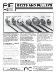
Belt Field Splicing Kit Is Easy To Use<br />
Two New Pitch Sizes Added To Belt Line<br />
Now easily splice No-Slip, No-Slide belts using this simple kit.<br />
It <strong>com</strong>es with <strong>com</strong>plete instructions. It’s the perfect choice for<br />
those doing field repairs and prototyping.<br />
Also checkout our expanded product line of belts now<br />
including two new pitches — 24DP and .25”. All PIC belts and<br />
pulleys are available on Autodesk’s PartSpec. Use PartSpec<br />
and find out how easy it is to calculate belt center distances.<br />
PIC-STIX Framing Elements Make<br />
Support Construction Easy<br />
The PIC-STIX line just doubled in size with the addition of our<br />
new line of light-weight miniature extrusions. It’s now easier<br />
than ever to construct structural assemblies using simple<br />
hand tools. Why pay for customized constructions when you<br />
can do it yourself.<br />
©2007, Precision Industrial Components LLC. PIC Design is a registered trademark of Precision Industrial Components LLC. Printed in the U.S.A.<br />
PIC, , , NO-MAR, NO-SLIP, NO-SLIDE, *E*P*S, Silver-Grip, PIC STIX, and Twin Track are the trademarks of Precision Industrial Components LLC.
“Twin Track”<br />
Linear Motion<br />
System<br />
Not only does “Twin Track” represent a significant<br />
price breakthrough, but it also offers users a host of<br />
design features not previously available in a single<br />
system. Twin Track is designated as System 10 and<br />
is fully described in Section 1 of this catalog.<br />
System 10 is available pre-assembled with many<br />
options to choose from.<br />
A one-piece plate and rail support assures<br />
parallelism and ease of set-up. Misalignment is<br />
eliminated because independent supports are no<br />
longer employed. Although standardized, System 10<br />
provides enhanced versatility because it is available<br />
in a choice of 10 travel lengths and 13 different lead<br />
screws. Motor mounts conform to either NEMA 23<br />
or 34. A hand crank version is also offered.<br />
Self-aligning recirculating ball bearings or<br />
economical engineered plastic bearings further add<br />
to the versatility of System 10.<br />
Positioning<br />
Tables With<br />
Extended Travel<br />
Lengths<br />
PIC delivers again on its promise of providing<br />
economically priced positioning tables without<br />
sacrificing quality. (See Section 1 of this catalog.)<br />
Straight line accuracy is .0007 inches per inch of<br />
travel. Repeatability and lead accuracy are .0004<br />
inches and .003 inches per foot, respectively. Best of<br />
all, travel lengths now range from 2 to 12 inches.<br />
Combine these positioning tables to form X-Y<br />
systems. Add a bracket and you can configure an<br />
X-Y-Z system. Get them with or without motor<br />
mounts and with a broad range of lead screw<br />
options. And now with a load handling capability of<br />
over 100 pounds, they’re more versatile than ever.<br />
Universal Lateral<br />
Shaft Couplers<br />
Now Feature<br />
Inch/Metric<br />
Models<br />
The PIC family of universal lateral couplings now<br />
feature 27 bore <strong>com</strong>binations, providing flexible<br />
coupling of inch-to-inch, metric-to-metric, and<br />
inch-to-metric shafts. See Section 7 for <strong>com</strong>plete<br />
product details.<br />
PIC universal lateral couplings <strong>com</strong>pensate for<br />
both lateral and angular misalignments of .050 inch<br />
and 10º, respectively. Delrin constructed bodies<br />
provide effective electrical insulation. Hubs are<br />
fabricated in nickel plated zinc for corrosion<br />
resistance.<br />
PIC universal lateral couplings are <strong>com</strong>petitively<br />
priced, <strong>com</strong>pactly designed to save space, and<br />
require no maintenance or lubrication.<br />
Finished Belt<br />
Fabrication Is<br />
Easy With New<br />
Splicing Kit<br />
PIC Design has always been the acknowledged<br />
leader in the design and fabrication of high<br />
performance positioning belts and pulleys,<br />
described in Section 5 of this catalog. To <strong>com</strong>plement<br />
our line of No-Slip and No-Slide belts, we<br />
now offer a new series of Belt Field Splicing Kits.<br />
Belts can now be assembled in the field from bulk<br />
stock. This capability is particularly useful for<br />
those engaged in prototyping operations or repair.<br />
The kit consists of a ratcheting plier, belt<br />
positioning fixture, knife, stripper/cutter, and a<br />
supply of ferrules. The fixture assures that the<br />
belt pitch will be accurate over the splice area.<br />
The ratcheting plier-die set <strong>com</strong>bination assures<br />
a consistently crimped ferrule.<br />
To add flexibility, other belt configurations can<br />
be crimped by simply purchasing the appropriate<br />
positioning fixture and a supply of ferrules.<br />
PIC-STIX<br />
Modular Framing<br />
Elements<br />
The PIC-STIX family of structural construction<br />
<strong>com</strong>ponents has been doubled in size by the<br />
addition of new light-weight miniature extrusion and<br />
associated hardware. See Section 9 of this catalog<br />
for the whole story and find out how easy it is to<br />
construct a wide range of structures using simple<br />
hand tools. T-slots in the extruded members easily<br />
accept T-bolts and T-nuts for fastening.<br />
PIC can ship the extrusions pre-cut to your size<br />
or in bulk lengths. We’ll even ship <strong>com</strong>plete kits or<br />
finished assemblies. PIC-STIX are the ideal way to<br />
quickly construct machine supports, platforms for<br />
linear motion systems, safety guards, and robotic<br />
systems.
MOTION/ POSITIONING<br />
PRODUCTS<br />
PRECISION MECHANICAL<br />
COMPONENTS<br />
GEAR PRODUCTS<br />
ii
1X1, 1X2, 2X2 Miniature, 1X1, 1X1.5, 1.5X1.5, 1.5X3,3X3 Standard,<br />
Brackets, Fasteners, Handles, Casters, Hinges etc.<br />
Precision Mechanical Component Kits, Socket Head Key Set<br />
iii
CATALOG SERIES INDEX<br />
If a Part Number is known, this index will assist in identifying and locating the part in the <strong>Catalog</strong>.<br />
CATALOG<br />
SECTION<br />
SERIES DESCRIPTION PAGE<br />
CATALOG<br />
SECTION<br />
SERIES DESCRIPTION PAGE<br />
CATALOG<br />
SECTION<br />
SERIES DESCRIPTION PAGE<br />
A1 to A8 Shafts, Precision Ground 6-22 to 6-23<br />
A9 Rod, Threaded 6-21<br />
A10 Shafting - Hardended 4-3 & 6-25<br />
A10-D Shafting - Hardened Predrilled 4-4<br />
A10L Shafting - Hardened 4-3 & 6-25<br />
A10-X-SR Shaft and Support Rails Assemblies 4-5<br />
A11 Shafting - 303 S.S. 4-3 & 6-25<br />
A11-X-SR Shafting and Support Rail Assemblies 4-5<br />
A12 Shafting 440C S.S. 4-3, 4-8 & 6-25<br />
A12-D Shafting - 404C S.S. Predrilled 4-4<br />
A12-X-SR Shaft and Support Rail Assemblies 4-5<br />
AA Bearing Housings 6-14<br />
AB Gears-Spur, Non-Metallic 12-31 to 12-34<br />
AC,AD Gears-Helical 12-45<br />
ACS Shafting for Instrument Linear Bearings 4-8<br />
AE5 to AE18 Pullleys-Grooved 5-38 to 5-40<br />
AF2 to AF6 Round Belt 5-38 to 5-40<br />
AG Racks-Precision 12-29 & 12-30<br />
AH,AJ Washers-Thrust 6-11<br />
AK,AL Balls-Steel, Nylon 6-18<br />
AM Bearings-Bronze,Precision 6-11<br />
ANR1 ACME Power Nuts 3-10<br />
ANR2 ACME Anti-Backlash Nuts 3-11<br />
ANR3 Acme Adjustable Compliant Nut 3-12<br />
AP-3 Mounting Plate-Bearing 6-14<br />
ARS ACME Lead Screws 3-9<br />
AU Shaft Extensions 6-21<br />
AW,AX Dial Sets-Disc & Drum 8-22 & 8-23<br />
AY,AZ Springs-Compression Extension 8-19<br />
B1,B2 Spacers,Shim-Laminated Brass 6-18<br />
B3 Spacers,Shim-Outer Race 6-16<br />
B4 to B15 Spacers,Shim-Precision 6-17<br />
B10,B11 Bearings,Bronze-Oil Impregnated 6-6<br />
B14,B15 Bearings, Sleeve-Teflon 6-10<br />
BA Miter & Bevel Gear Boxes 11-5<br />
BB Breadboard Components 8-25<br />
BC Universal Joints 7-15<br />
BE-1 to BE-3 Set Screw-Slotted Head 8-7<br />
BE-16,-66,-67 Springs-Anti-Backlash 8-21<br />
BFC Ball Screw Mounting Flanges 3-16 – 3-20<br />
BN Ball Screw Nuts 3-16 – 3-20<br />
BNW Ball Screw Wipers 3-16 – 3-20<br />
BF, BS Non-Metallic Bearings 6-8<br />
BG Knobs 8-25<br />
BH Hubs,Gear,Cluster 12-68<br />
BLC,BLO Bearings Linear Ceramic Coated 4-12<br />
BP,BQ,BU Blanks-Gear,Pin Hub,Hubless 12-53<br />
BS Ball Screws 3-16 – 3-20<br />
C1 Collars-Precision 6-18<br />
C2-15 Set Screws-Slotted Head 8-7<br />
CN,CO Gears-Cluster 12-35<br />
CR Keys-Woodruff 8-24<br />
CS-1 to -36 “No Mar” Set Screws 8-6<br />
CS-40 to -50 Socket Head Keys & Sets 10-3<br />
CS-51 to -67 “Silver Grip” Set Screws 8-5<br />
CS-85 to -99 Brass Tip Set Screws 8-7<br />
D1 Couplings-Sleeve 7-12<br />
D2 to D14 Pins-Dowel-Slip Fit 8-14<br />
D15 to D22 Pins-Dowel, Hardened-Press Fit 8-16<br />
D25 to D32 Pins-Dowel, Hardened-Press Fit 8-16<br />
D33 Washers-Curved 8-9<br />
D40 to D50 Pins-Dowel-Interference Fit 8-14<br />
D6-1 to -6 Washers-Wave Spring 6-14<br />
D6-20 to -27 Washers-Belleville Spring 8-8<br />
DJ & DQ Worm & Wheel Assemblies 11-4<br />
DU Helical Gear Assemblies 11-5<br />
E1 to E19 Bearings-Ball, Precision 6-4 & 6-5<br />
E1 to E4 Bearings-Extended Inner Race 6-3<br />
E5 Bearings-Extra Thin 6-3<br />
E8 Bearings-Tapered O.D. 6-3<br />
EC Roller Clutches 7-7<br />
EF Handles-Chassis 8-20 & 8-21<br />
EG Spacer Post-Threaded 8-13<br />
EG-375 to 625B Non-Corrosive Ball Bearing 6-10<br />
EJ,EK Gears-Spiral 12-52<br />
EL Chain-Miniature Pitch 5-41<br />
EL25 Chain-.250 Pitch 5-41<br />
EM Sprockets-Chain 5-42<br />
EM25 Sprockets-Chain 5-41<br />
EPS-A Timing Belts-.080 Pitch 5-26<br />
EPS-C Timing Belts-.-0816 Pitch 5-28<br />
EPS-D Timing Belts-1/5 Pitch 5-30<br />
EPS-F Timing Belts-3mm 5-34<br />
EPS-G Timing Belts-5mm 5-36<br />
EPS-J Timing Belts-3/8 Pitch 5-33<br />
ES Gear Boxes-Servo 11-4<br />
ES-250 to 1000 Non-Corrosive Ball Bearing 6-10<br />
ET Thrust Bearings 6-11<br />
EU Geneva Mechanisms 11-7 & 11-8<br />
EV Intermittent Motion Assembly 11-6<br />
F1,F2,F3 Spacer Posts-Square 8-13<br />
F4 to F9 Gears-Pinion Shafts 12-28<br />
F8BS No-Slide Belts-40DP 5-20<br />
F8P No-Slide Pulleys-40DP 5-20<br />
F20B No-Slide Belts-1/5" Pitch 5-21<br />
F20P No-Slide Pulleys-1/5" Pitch 5-21<br />
F20T No-Slip Belts-Triple Core 20DP 5-14<br />
F24 No-Slip Belts-24DP 5-10<br />
F24G No-Slip Sprockets-24DP 5-11<br />
F25CS No-Slip Belts-1/4CP 5-18<br />
F25G No-Slip Sprockets-1/4CP 5-19<br />
F32CS “No Slip” Belts-32DP-Twin Core 5-8<br />
F32G,F32J “No Slip” Pulleys-32DP-Twin Core 5-9<br />
F37B No-Slide Belts-3/8 Pitch 5-22<br />
F37P No-Slide Pulleys-3/8 Pitch 5-22<br />
FA,FS “No Slip” Belts-32DP 5-6<br />
FC,FD “No Slip” Pulleys-32DP 5-7<br />
FER Ferulles-No-Slide Belts 5-5<br />
FL Flange,Lead Screw 3-13<br />
FLA,FLS “No Slip” Belts-20DP 5-14<br />
FLG,FLH “No Slip” Pulleys-20DP 5-15<br />
FMA,FMS “No Slip” Belts-20DP-Twin Core 5-16<br />
FMG,FMH “No Slip” Sprockets-20DP 5-17<br />
FRA,FRS “No Slip” Belts-.1475CP-Twin Core 5-12<br />
FRG,FRH Sprockets-.1475CP 5-13<br />
F_-SK Splice Kit 5-5<br />
G,N,R Kits-Breadboard-1/4 Shaft 10-3<br />
G1 to G83 Gears-Spur,Pin Hub Index 12-4<br />
H1 to H60 Gears-Spur,Split Hub Index 12-4<br />
J1 to J28 Gears-Spur, Hubless Index 12-4<br />
K1-1 to K1-14 Hubs-Gear & Dial-Pin Type 12-67<br />
K1-50 to K1-52A Hubs - 5/16 to 1/2 Bore - Pin Type 12-68<br />
K2-1 to K2-14 Hubs-Gear & Dial-Split Type 12-67<br />
K2-50 to K2-52A Hubs-5/16 to 1/2 Bores Split Type 12-68<br />
KE Kits-Educational 10-1 & 10-2<br />
L1, L4, L5, L6 Clamps-Hub,Standard<br />
& Miniature 6-19 & 6-20<br />
L2, L3 Cleats-Motor Mount 8-12 & 8-13<br />
LMB Flange-Lead Screw 3-13<br />
LS3- to LS10 Linear Systems 1-5 to 1-11<br />
M1 to M5 Dials-Disc & Drum; Index 8-22 to 8-24<br />
MA10 Shafting - Hardened 4-3 & 6-25<br />
MA10-D Shafting Hardened - Predrilled 4-4<br />
MA10-X-SR Shaft and Support Rail Assemblies 4-5<br />
MA11 Shafting 303 S.S. 4-3 & 6-25<br />
MA11-X-SR Shaft and Support Rail Assemblies 4-5<br />
MA12 Shafting 440C S.S. 4-3 & 6-25<br />
MA12-X-SR Shaft and Support Rail Assemblies 4-5<br />
MBF & MBS Non-Metallic Bearings 6-9<br />
MBG1 to MBG8 Bearings-Ball,Precision 6-5<br />
(Extra Small and Standard)<br />
MBG9 to MBG10 Bearings-Bronze, Oil Impregnated 6-7<br />
MBG10 - MBG40 Bearings - Ball ISO Normal 6-5<br />
MBL1 Ballls-Precision, Hardened 6-18<br />
MBLA Linear Bearings Ceramic Coated 4-12<br />
Adjustable<br />
MBLC Linear Bearings Ceramic Coaated 4-12<br />
Closed<br />
MBLO Linear Bearings Ceramic Coated 4-12<br />
Open<br />
MBW1 Washers-Belleville Spring 8-8<br />
MCH2 to MCH4 Clutches-Slip,Continuous, 7-4 & 7-6<br />
Adjustable, Intermittent<br />
MCS1 Screws-Captive, Slotted Head 8-9<br />
MCU1 & MCU2 Couplings-Bellows 7-9<br />
MCU3 & MCU4 Couplings-Zero Adjustable 7-9<br />
MCU5 & MCU6 Couplings-Sleeve 7-12<br />
MCU7 & MCU8 Couplings-Flexible 7-10<br />
MCU9 & MCU10 Couplings-Oldham 7-11<br />
MCU13 & MCU14 Couplings-Multi Jaw 7-11<br />
MCU15 Couplings-Wafer Spring 7-8<br />
MCU17 - MCU19 Couplings-Slip, Continuous, 7-5 & 7-6<br />
One Way Adjustable<br />
MCU20 Couplings- Sleeve 7-12<br />
MDP1 to MDP20 Pins-Dowel, Precision 8-15<br />
MEG & MES Non-Corrosive Ball Bearing 6-10<br />
MF8 No-Slide Pulley-40DP Metric Bores 5-20<br />
MF20G No-Slip Sprocket-20DP Metric Bores 5-15<br />
MF20P No-Slide Pulley-1/5" Pitch Metric Bores 5-21<br />
MF24G No-Slip Sprockets-24DP Metric Bores 5-11<br />
MF25G No-Slip Sprockets-1/4"CP Metric Bores 5-19<br />
MF32 No-Slip Sprockets-32DP Metric Bores 5-9<br />
MF37P No-Slide Pulley-3/8 Pitch Metric Bores 5-22<br />
MFMG No-Slip Sprockets 20DP 5-17<br />
MFRG No-Slip Sprockets .1475 5-13<br />
MGB3 Gear Boxes-Servomechanisms 11-6<br />
MGP1 to MGP4 Pulleys-Geared, “No-Slip” 5-7<br />
MHS1 to MHS12 Gears-Spur,Hubless 12-54 to 12-66<br />
MHU1 to MHU5 Hubs-Gear 12-68<br />
MHU6 to MHU9 Hubs-Gear & Dial 12-67<br />
MMS1 to MMS4 Sprockets 5-42<br />
MPA Linear Bearing Recirculating Ball - 4-9<br />
Adjustable<br />
iv<br />
Phone: 800-243-6125 ■ FAX: 203-758-8271<br />
E-Mail: sales@pic-design.<strong>com</strong><br />
DESIGN<br />
®<br />
www.pic-design.<strong>com</strong><br />
Interactive catalog ■ CAD ■ e-<strong>com</strong>merce
CATALOG SERIES INDEX<br />
If a Part Number is known, this index will assist in identifying and locating the part in the <strong>Catalog</strong>.<br />
CATALOG<br />
SECTION<br />
SERIES DESCRIPTION PAGE<br />
CATALOG<br />
SECTION<br />
SERIES DESCRIPTION PAGE<br />
CATALOG<br />
SECTION<br />
SERIES DESCRIPTION PAGE<br />
MPFL & MPFLO Metric Linear Bearing-Self-Aligning 4-10<br />
MPL Linear Bearing Recirculating Ball - 4-9<br />
Closed<br />
MPL-XRF Linear Bearing Flanged - Round 4-7<br />
MPL-XSF Linear Bearing Flanged - Square 4-7<br />
MPLA Linear Bearings Engineered Plastic - 4-11<br />
Adjustable<br />
MPLC Linear Bearings Engineered Plastic - 4-11<br />
Closed<br />
MPLO Linear Bearings Engineered Plastic - 4-11<br />
Open<br />
MPO Linear Bearings Recirculating Ball - 4-9<br />
MPSR Shaft Support Rails 4-4<br />
MPSR-X-PD Shaft Support Rails Predrilled 4-5<br />
MR Bore Reducers, Inch to Metric 7-14<br />
MRR1 & MRR2 Rings-Retaining,Internal& External 8-11<br />
MRR3 Rings-Retaining,Plain (“E Ring”) 8-11<br />
MS10 Universal Bearing Housing 3-14<br />
MSA Housing/Pillow Block-Linear Bearing - 4-14<br />
Adjustable<br />
MSB1 & MSB3 Screws-Shoulder, Slotted Head 8-2<br />
MSB2 & MSB4 Screws-Shoulder ,Socket Head 8-3<br />
MSB7 & MSB8 Screws - Shoulder, Phillips Head 8-4<br />
MSC Housing/Pillow Block-Linear Bearing - 4-14<br />
Closed<br />
MSC1 Collars-Set Screw 6-18<br />
MSG3 to MSG34 Gears-Spur,Pin Hub 12-54 to 12-66<br />
MSG35 - MSG50 Gears-Spur,Split Hub 12-54 to 12-66<br />
MSH1 to MSH7 Shafting-Ground,Precut<br />
& Long Lengths 6-24<br />
MSHA Metric Shaft Support Blocks/Hangers 4-6<br />
MSO Housing/Pillow Block-Linear Bearing - 4-14<br />
Open<br />
MSP1 to MSP6 Spacers-Shaft, Shim 6-16 & 6-17<br />
MSR1 Reducers-Speed Miniature 11-1<br />
MSR2 & MSR3 Reducers-Speed Miniature 11-2<br />
MSS2 Set Screws-”No Mar”,Socket Type 8-6<br />
MSS3 Set Screws-”Silver’Grip”,Socket Type 8-5<br />
MSS4 Set Screws-Cup Point,Socket Type 8-7<br />
MPFL Metric Linear Bearing-Self Aligning 4-10<br />
MT Coupling-Flexible Zero Backlash 7-13<br />
MTN1 Nuts,Thumb,Knurled 8-18<br />
MTS1 Screws-Thumb,Knurled 8-18<br />
MUJ1 Universal Lateral 7-10<br />
MUJ2 to MUJ4 Universal Joints 7-15<br />
N1 to N3 Gears-Miter & Bevel 12-50 to 12-51<br />
N1-AB to N3-AB Gears-Miter-Anti-Backlash 12-51<br />
N4,N5 Couplings-Multi-Jaw 7-11<br />
P1-21 to P1-27B Cam Follower - Ball or Bronze 6-13<br />
P2 to P70 Gears-Spur,Anti-Backlash 12-36 to 12-44<br />
P101 to P2201 Positioners with Micrometers 2-12<br />
PA,PL,PO Linear Bearings-Closed,<br />
Adjustable, Open 4-9<br />
PB Ball Slides 2-4<br />
PBC Ball Slide Table (Positioning Stage) 1-13<br />
PBE Economy Ball Slides 2-5<br />
PE3 to PE16 Rod Ends 6-12<br />
PE12 Spherical Bearings 6-13<br />
PFL Linear Bearings-Self Aligning 4-10<br />
PFLO Linear Bearings - Recirculating 4-10<br />
PK Lead Screw - Antibacklash Nut 3-7<br />
PLA Linear Bearings Engineered Plastic - 4-11<br />
Adjustable<br />
PLC Linear Bearings Engineered Plastic - 4-11<br />
Closed<br />
PLO Linear Bearings Engineered Plastic - 4-11<br />
Open<br />
PLS Linear Bearings Instrument Series 4-8<br />
PL-XRF Linear Bearing Flanged - Round 4-7<br />
PL-XSF Linear Bearing Flanged - Square 4-7<br />
PNB1 to PNB6 Rails 2-9<br />
PNBT-A Aluminum Crossed Roller Slides 2-6<br />
PNBT Steel Crossed Roller Slides 2-7<br />
PRB Crossed Roller Slides 2-8<br />
PS Lead Screws (PS Style) 3-5<br />
PSR Shaft Support Rails 4-4<br />
PSR-X-PD Shaft Support Rails - Predrilled 4-5<br />
PTO-A Timing Belt Pulleys-.080 Pitch 5-26 & 5-27<br />
PTO-C Timing Belt Pulleys-.0816 Pitch 5-28 & 5-29<br />
PTO-D Timing Belt Pulleys-1/5 Pitch 5-30 to 5-32<br />
PTO-F Timing Belt Pulleys-3mm 5-34 & 5-35<br />
PTO-G Timing Belt Pulleys-5mm 5-36 & 5-37<br />
PTO-J Timing Belt Pulleys-3/8 Pitch 5-33<br />
PV Lead Screw - Antibacklash Nut 3-8<br />
PZ Lead Screw - Antibacklash Nut 3-6<br />
Q1 to Q12 Gears-Worm & Worm Wheel 12-46 to 12-48<br />
Q13 to Q20 Gears-Worm Wheel-<br />
Anti-Backlash 12-47 to 12-49<br />
R Bore Reducers, Inch to Inch 7-14<br />
R3 Clutch-Slip Assembly 7-6<br />
R1,R2,R5,R6 Hangers-Shaft 6-15<br />
RD Rubber Covered Drive Rollers 4-15<br />
RS Rubber Cover Idler Rollers 4-15<br />
RW1 to RW4 Shaft Mounted Clutches 7-4<br />
RX1 to RX4 Flange Mounted-Power On Brakes 7-3<br />
RY5 to RY8 Flange Mounted-Power Off Brakes 7-3<br />
S1,S3,S4 Hangers-Component Mounting 6-26<br />
S5,S8 Mounting Accessories-Linear Bearings 4-13<br />
S7 Hangers-Shaft 4-6<br />
S10 & S12 Bearing Housing 3-14<br />
SCA Accessories — Handles, Hinges, 9-9 to 9-11<br />
Door Latch, Roller, Slide Track,<br />
Panel Gasket<br />
SCB Angle Brackets 9-5<br />
SCB Corner - Braces 9-7<br />
SCB1 Panel Mounting Angle 9-6<br />
SCE Leveling Plates, Casters 9-10<br />
SCH Fastening Hardware 9-7 to 9-9<br />
SCX Corner - Brackets 9-6<br />
Extrusions<br />
SEB Ball Slide Guide 2-10<br />
SHA Shaft Support Blocks/Hangers 4-6<br />
SP Shim Pack 3-4<br />
SX Aluminum Extrusions 9-3 & 9-4<br />
T1 Couplings-Bellows 7-9<br />
T7,T8 Couplings-Oldham,Miniature 7-11<br />
T9,T10 Couplings-Zero Adjustable 7-9<br />
T11,T12 Coupling-Flexible 7-10<br />
T13E Coupling ‘Spider’ 7-7<br />
16T Spur Gears 16 pitch 12-5<br />
24T Spur Gears 24 pitch 12-8<br />
32T Spur Gears 32 pitch 12-11<br />
32HT Spur Gears 32 pitch 12-10<br />
TE Belt Tensioner 5-3<br />
T14 Coupling & Slip Clutch 7-6<br />
T15 Coupling-Wafer Spring 7-8<br />
T16 Coupling-Universal Lateral 7-10<br />
T17 Clutch-Continuous Slip 7-4<br />
T18 Coupling-Continuous Slip 7-5<br />
T21-T24 Coupling-Flexible “K” Type 7-14<br />
T22 Coupling-Flexible-Zero Backlash 7-13<br />
T25 Slip Clutch - Adjustable 7-5<br />
U1 to U4 Speed Reducers-<br />
Sizes 10,11,18 11-1 & 11-2<br />
U7,U8 Gear Heads-Sizes 11,18 11-3<br />
W3 Hand Cranks 8-25<br />
Y9 Screws-Captive 8-9<br />
Y11 Set Screws-Socket Head 8-7<br />
Z1 to Z5 Retaining Rings 8-10 & 8-11<br />
2040 to 2065 Studs-Dbl. Threaded 6-21<br />
2100 to 2106 Studs-Threaded, Swivel 8-18<br />
3140 to 3145 Nuts-Knurled,Swivel 8-18<br />
3150 to 3156 Washers-Precision 8-9<br />
3160 to 3176 Washers-Swivel 8-18<br />
4010 to 4094 Screws-Thumb,Knurled 8-17<br />
4310 to 4465 Screws-Shoulder 303 S.S. 8-2 & 8-4<br />
4510 to 4665 Screws-Shoulder 416 S.S. 8-2 & 8-4<br />
4710 to 4854 Screws-Shoulder, Phillips Head 8-4<br />
www.pic-design.<strong>com</strong><br />
Interactive catalog ■ CAD ■ e-<strong>com</strong>merce<br />
DESIGN<br />
®<br />
Phone: 800-243-6125 ■ FAX: 203-758-8271<br />
E-Mail: sales@pic-design.<strong>com</strong><br />
v
PIC DESIGN WORLDWIDE SALES<br />
PIC DESIGN maintains a Worldwide network of<br />
Sales Representatives, Agents and Authorized<br />
Distributors who stand ready to assist you in your<br />
application of standard catalog products or to<br />
help you with your modified or special build to<br />
print designs. Contact us for the sales help<br />
nearest to you or visit our website for the<br />
<strong>com</strong>plete listing.<br />
Phone 203-758-8272<br />
800-243-6125<br />
Fax 203-758-8271<br />
Email info@pic-design.<strong>com</strong><br />
Website www.pic-design.<strong>com</strong><br />
AUTHORIZED PIC DESIGN DISTRIBUTORS<br />
Don’t be misled by <strong>com</strong>panies that say they can provide you with PIC precision <strong>com</strong>ponents. Unfortunately,<br />
there are firms that will take your order and substitute parts of questionable origin. Here at PIC Design, we<br />
feel that in the over 50 years we’ve been in business, many design engineers and the <strong>com</strong>panies they work<br />
for have gained confidence in PIC. They know PIC as the original <strong>com</strong>pany to provide precision mechanical<br />
<strong>com</strong>ponents of the highest quality. When they specify PIC Design, they expect and deserve to get products<br />
supplied by PIC Design. For the name of the authorized distributor near you, contact us.<br />
TERMS AND CONDITIONS<br />
Payment Terms:<br />
U.S.A. — Net 30 days. Shipment F.O.B.<br />
Middlebury, Connecticut.<br />
All shipments are insured.<br />
Worldwide — Terms vary from region to<br />
region. Check with the local PIC<br />
representative for your area.<br />
Prices:<br />
To secure current prices in the quantities you<br />
require, contact PIC Design or your nearest PIC<br />
representative. All of our standard catalog products<br />
have price and delivery information available in the<br />
e-<strong>com</strong>merce section of our website at www.picdesign.<strong>com</strong>.<br />
In addition, orders can be placed<br />
using major credit cards or with prior arrangements<br />
– open account.<br />
Technical Information:<br />
The technical information in this catalog supersedes<br />
all previous catalog information and is<br />
subject to change without notice. PIC Design<br />
maintains a <strong>com</strong>plete up to data catalog on our<br />
website at www.pic-design.<strong>com</strong>. Beyond PDF pages<br />
of this catalog we have an interactive version with<br />
design aids and wizards to help the design process.<br />
We also have a <strong>com</strong>plete library of 3D/2D CAD<br />
drawings of every PIC <strong>com</strong>ponent in all the<br />
standard formats.<br />
Credit:<br />
Until satisfactory credit has been established we<br />
reserve the right to ship C.O.D.<br />
Minimum Order:<br />
PIC minimum order billing is $50.00<br />
Method of Shipping:<br />
PIC Design has daily scheduled UPS (all methods)<br />
and FedEx (small packages) pick up. However, we<br />
have on call almost all other carriers.<br />
Shortages:<br />
Claims for shortages must be made within 10 days<br />
of receipt of material.<br />
Returns and Exchanges:<br />
Request for returns of standard PIC catalog<br />
products must be submitted for approval within 15<br />
days of receipt by customer. An authorized return<br />
number must be secured from PIC prior to return of<br />
material. All unauthorized returns will be shipped<br />
back to the customer at customer’s expense.<br />
PIC will inspect authorized return material and, if<br />
accepted, will advise customer of charges for<br />
handling, inspection and restocking.<br />
No returns will be authorized or credit allowed for<br />
used or non-standard items, modified catalog items<br />
or catalog items made to customer order in<br />
production runs.<br />
Cancellations:<br />
In-process orders, which are terminated by the<br />
customer prior to delivery, are subject to cancellation<br />
charges at the discretion of PIC.<br />
Telephone, FAX:<br />
Many of our customers use the telephone and FAX to<br />
speed their orders on the way. We provide full service<br />
to accept such orders; however, errors in transmission<br />
are the customer’s responsibility. All confirming<br />
formal orders must be marked “CONFIRMING” or the<br />
cost incurred in duplicate shipments will be the<br />
customer’s responsibility.<br />
Note:<br />
For detailed terms and conditions, please contact PIC<br />
Design or review them on our website at<br />
www.pic-design.<strong>com</strong>.<br />
Precision Industrial Components, LLC<br />
86 Benson Road, P.O. Box 1004<br />
Middlebury, CT 06762-1004<br />
Telephone: (800) 243-6125<br />
(203) 758-8272<br />
FAX: (203) 758-8271.<br />
E-Mail: info@pic-design.<strong>com</strong><br />
Hours: 8:00 am to 5:00 pm Eastern Time.<br />
vi<br />
Phone: 800-243-6125 ■ FAX: 203-758-8271<br />
E-Mail: sales@pic-design.<strong>com</strong><br />
DESIGN<br />
®<br />
www.pic-design.<strong>com</strong><br />
Interactive catalog ■ CAD ■ e-<strong>com</strong>merce
R<br />
DESIGN<br />
RECISION<br />
NDUSTRIAL<br />
OMPONENTS<br />
R<br />
LINEAR MOTION SYSTEMS<br />
User-assembled or Pre-assembled<br />
PIC now offers a <strong>com</strong>prehensive line of<br />
linear motion systems.<br />
Single sourcing eliminates the need for<br />
extensive, expensive <strong>com</strong>ponent and system<br />
design and time consuming searches through<br />
different manufacturers’ catalogs for all required<br />
designs and sizes.<br />
The first few pages offer a guide to linear<br />
motion calculations, for determining effective<br />
loads, life of linear bearings, and shaft<br />
deflections. These pages are not meant to<br />
replace the thinking of an engineer but rather to<br />
assist.<br />
System 3 is made up of our standard<br />
<strong>com</strong>ponents found in section 4 of this catalog.<br />
This popular configuration is made up of two<br />
linear bearings mounted in housings, with a<br />
shaft and shaft support rail.<br />
System 9 is available with or without bellows<br />
covers. This is a modular pre-assembled<br />
precision product, with 4 linear bearings<br />
mounted in housings with two parallel shafts<br />
mounted to a base plate, with a table top, lead<br />
screw and coupling. The key to this unit is<br />
standard one-size shafting, which allows for<br />
quick delivery at a discounted price. System 9<br />
is ideal for vertical applications. The optional<br />
protective Bellows Cover is made of<br />
polyurethane coated nylon. These covers<br />
protect the shafting and lead screw from<br />
damage-causing debris.<br />
System 10 is available with or without<br />
bellows covers. It is similar to system 9, but<br />
the shafts are fully supported by a one piece<br />
integral rail. As with system 9 the one size<br />
shafting allows for quick delivery at a<br />
discounted price. System 10 is ideal for<br />
applications that require greater travel.<br />
Positioning Stages: PIC’s industrial grade<br />
tables provide solutions for indexing where<br />
the strict requirements of scientific stages are<br />
not needed. Mounting holes in top and base<br />
are located to easily allow two stages to be<br />
configured as an X-Y positioner. Ready to<br />
hook up to your standard NEMA 23 motor.<br />
www.pic-design.<strong>com</strong><br />
Interactive catalog ■ CAD ■ e-<strong>com</strong>merce<br />
DESIGN<br />
®<br />
Phone: 800-243-6125 ■ FAX: 203-758-8271<br />
E-Mail: sales@pic-design.<strong>com</strong> 1-1
LINEAR MOTION SYSTEMS<br />
STEP<br />
CALCULATION OF SYSTEM LOADING<br />
AND BEARING SELECTION<br />
LOAD CALCULATION<br />
The main factors involved in the selection of bearing material and size are the load on a single bearing<br />
and the total travel life required. The load on a single bearing varies with the position of the center of<br />
gravity on the table top or carriage. To calculate the load on a single bearing:<br />
1. For system 3, use load calculation diagram 1 for vertical applications, and load calculation<br />
diagram 2 for horizontal applications.<br />
2. For other frequently used system configurations, use load calculation diagram 3 for horizontal<br />
axis, load calculation diagram 4 for vertical axis, and load calculation diagram 5 for vertical lateral<br />
axes.<br />
LOAD CALCULATION DIAGRAMS<br />
DIAGRAM 1<br />
DIAGRAM 4<br />
DIAGRAM 2<br />
DIAGRAM 5<br />
DIAGRAM 3<br />
P = FORCE ON BEARINGS<br />
W = WEIGHT ON SYSTEM<br />
1-2<br />
Phone: 800-243-6125 ■ FAX: 203-758-8271<br />
E-Mail: sales@pic-design.<strong>com</strong><br />
DESIGN<br />
®<br />
www.pic-design.<strong>com</strong><br />
Interactive catalog ■ CAD ■ e-<strong>com</strong>merce
LINEAR MOTION SYSTEMS<br />
STEP<br />
BEARING SELECTION<br />
Two types of bearings, self-aligning recirculating<br />
ball bearings and engineered plastic bearings, are<br />
available from PIC for use in linear motion<br />
systems. Both types are available in inch or<br />
metric sizes, and closed or open styles.<br />
SELF-ALIGNING BEARINGS<br />
The formulas and tables listed below will enable<br />
the designer to select the proper self-aligning<br />
bearings to meet the required life.<br />
Basic Dynamic Load Rating<br />
and Life Expectancy<br />
The basic dynamic load rating of a selfaligning<br />
bearing is the load which allows a<br />
rating life of 2,000,000 inches or 50,000<br />
meters of travel, without change in magnitude<br />
or direction. The rating life of a bearing for a<br />
particular application can be calculated from<br />
the following equations:<br />
For inch calculations,<br />
L=<br />
f h ●<br />
C 3 ● 2<br />
● 10<br />
6<br />
f w P<br />
For metric calculations,<br />
L(km) = fh C 3<br />
● ●<br />
50<br />
f w P<br />
With:<br />
L = rating life in inches for inch calculations,<br />
in kilometers for metric calculations<br />
f h = hardness factor (1.0); shafts are<br />
60-65 HRC<br />
f w = load coefficient (refer to table 1)<br />
C = basic design load rating in pounds for<br />
inch calculations, in Newtons for metric<br />
calculations (refer to table 2 or 3)<br />
P = force in pounds for inch calculations,<br />
force in Newtons for metric calculations,<br />
determined from load calculation<br />
diagrams 1 through 5, as applicable<br />
Rating life in hours can be calculated from the<br />
travel distance per unit of time, as follows:<br />
L h =<br />
L<br />
2 L ● ●<br />
s n ●<br />
1 60<br />
With:<br />
L h = rating life in hours<br />
L s = stroke length in inches for<br />
inch calculations, in meters for<br />
metric calculations<br />
n 1 = rating in cycles per minute<br />
Table 2. C Dynamic Load Rating of Inch Bearings<br />
To calculate the basic dynamic load rating, use<br />
C=<br />
3<br />
.3/8 95 PFL-6 —<br />
L f<br />
● w ●<br />
.1/2 230 PFL-8 PFL0-8<br />
P<br />
2 10 6 .5/8 400 PFL-10 PFL0-10<br />
f ● h .3/4 470 PFL-12 PFL0-12<br />
the following formulas:<br />
Shaft Rating<br />
PIC Part No.<br />
Diameter (inch) (lb) Closed Open<br />
For distances in inches,<br />
.1/4 60 PFL-4 —<br />
1. 850 PFL-16 PFL0-16<br />
For distances in kilometers,<br />
1.1/4<br />
1.1/2<br />
1230<br />
1480<br />
PFL-20<br />
PFL-24<br />
PFL0-20<br />
PFL0-24<br />
C=<br />
3<br />
L f<br />
● w ●<br />
Table 3. C Dynamic Load Rating of Metric Bearings<br />
P<br />
1 ● 50 f h<br />
Shaft Diameter Rating<br />
(mm) (Newtons)<br />
PIC Part No.<br />
Example of Calculations using standard PIC<br />
<strong>com</strong>ponents<br />
Expected Life: 20,000 hours<br />
Number Of Bearings: 4<br />
Weight On Carriage: 175 lb<br />
Stroke Distance: 24 inches<br />
Traveling Speed: 1000 in. / min<br />
Cycle:<br />
2 x 24 inches<br />
Shaft:<br />
A10L series<br />
From the life expectancy in hours formula, the<br />
life expectancy in traveling distance is:<br />
L h =<br />
L<br />
2 L s n ●<br />
1 60<br />
L=L h<br />
● 2 L ● s<br />
● n ●<br />
1 60<br />
L = 20,000 ● 2 ● 24 ● 1000<br />
●<br />
60<br />
2 ● 24<br />
L = 1.20 x 10 9 inches<br />
From the dynamic load rating formula:<br />
C=<br />
C=<br />
3<br />
C = 553 lb<br />
L f<br />
● w<br />
2 ● 10 6 f h<br />
●<br />
P<br />
3<br />
1.2<br />
●<br />
10 9 1.5<br />
●<br />
●<br />
175<br />
2 ● 10 6 1.0 4<br />
The assumption is that the 175 pound load<br />
is distributed evenly between bearings;<br />
therefore, using diagram 3 with1-inch with 1-<br />
inch diameter bearings having a load capacity<br />
of 850 pounds is selected.<br />
Table 1. Load Coefficient<br />
Operating Conditions<br />
f w<br />
Operation at low speed (50 ft/ min or<br />
15 m/ min or less) without impulsive 1 - 1.5<br />
shock from outside<br />
Operation at intermediate speed<br />
(200 ft/min or 60 m/min or less) 1.5 - 2.0<br />
without impulsive shock<br />
Operation at high speed<br />
(over 200 ft/min or 60 m/min) 2.0 - 3.5<br />
with impulsive shock from outside<br />
CLOSED TYPE<br />
12 650 MPFL-12<br />
16 800 MPFL-16<br />
20 1500 MPFL-20<br />
25 2500 MPFL-25<br />
30 3200 MPFL-30<br />
40 5550 MPFL-40<br />
OPEN TYPE<br />
12 750 MPFL0-12<br />
16 920 MPFL0-16<br />
20 1560 MPFLO-20<br />
25 2600 MPFLO-25<br />
30 3330 MPFL0-30<br />
40 5740 MPFL0-40<br />
ENGINEERED PLASTIC<br />
LINEAR BEARINGS<br />
PIC self-lubricating plastic bearings are<br />
maintenance free, run quietly, are not subject<br />
to catastrophic failure, do not gall or brinell<br />
the mating shaft, and can run on “soft” noncorrosive<br />
303 stainless steel shafting. These<br />
bearings are also capable of operation in<br />
hostile environments and are interchangeable<br />
with PIC self-aligning, recirculating bearings.<br />
Bearing PV Rating<br />
The performance capabilities of engineered<br />
plastic linear bearings are defined by the<br />
PV rating of the bearings, where P is the<br />
pressure in pounds per square inch on the<br />
projected bearing area, and V is the<br />
velocity in feet per minute of the wear<br />
surface. Maximum PV for continuous<br />
operation is 7500 PSI/FPM. To calculate<br />
PV for a particular application, divide the<br />
total load in pounds on the bearing by the<br />
effective area in square inches, and<br />
multiply by the average bearing velocity in<br />
feet per minute.<br />
Example of Calculation:<br />
Number Of Bearings: 4<br />
Weight On Carriage: 175 lb<br />
Load Per Bearing: 175/4 = 43.75 lb<br />
Traveling Speed: 1000 in./min or<br />
83.33 ft/min<br />
Bearing Selected: PLC-16 (1 in. = ID,<br />
2.25 in. long = L)<br />
P= Load (lb.) 43.75<br />
= = 19.44 PSI<br />
ID L 1 2.25<br />
● ●<br />
PV = 19.44 83.33 = 1620 PSI/FPM<br />
●<br />
www.pic-design.<strong>com</strong><br />
Interactive catalog ■ CAD ■ e-<strong>com</strong>merce<br />
DESIGN<br />
®<br />
Phone: 800-243-6125 ■ FAX: 203-758-8271<br />
E-Mail: sales@pic-design.<strong>com</strong><br />
1-3
LINEAR MOTION SYSTEMS<br />
STEPDETERMINATION OF SHAFT DEFLECTION<br />
Once the appropriate bearing has been selected to fulfill the load requirements<br />
of the application, the shaft deflection must be determined. Dimensions and<br />
tolerances of PIC shafts are listed in table 4. The required shaft diameter is<br />
dictated by the ID of the selected bearing, and the deflection can be determined<br />
from table 5 or 6 for inch or metric systems, respectively.<br />
Table 4. Shaft Diameters and Tolerances<br />
Diameter<br />
PIC Series<br />
Tolerance<br />
(inch)<br />
(inch)<br />
.1/4 A10L-4 0.2495 / 0.2490<br />
.3/8 A10L-6 0.3745 / 0.3740<br />
.1/2 A10L-8 0.4995 / 0.4990<br />
.5/8 A10L-10 0.6245 / 0.6240<br />
.3/4 A10L-12 0.7495 / 0.7490<br />
1. A10L-16 0.9995 / 0.9990<br />
1.1/4 A10L-20 1.2495 / 1.2490<br />
1.1/2 A10L-24 1.4994 / 1.4989<br />
Table 5. Shaft Deflection Table (Inch Systems). Deflection Per Pound At Center Of Fixed Supporting Shaft.<br />
Shaft<br />
Length Of Unsupported Section (inches)<br />
Diameter<br />
(inches) 4 6 8 10 12 16 20 24 30 36 42 48 72<br />
1 /4 5.85 x 10 -5 1.98 x 10 -4 4.68 x 10 -4 9.15 x 10 -4 1.58 x 10 -3 3.75 x 10 -3 7.32 x 10 -3 1.26 x 10 -2 2.5 x 10 -2<br />
3 /8 1.20 x 10 -5 4.05 x 10 -5 9.63 x 10 -5 1.79 x 10 -4 3.25 x 10 -4 7.68 x 10 -4 1.43 x 10 -3 2.60 x 10 -3 4.83 x 10 -3 8.33 x 10 -3 1.32 x 10 -2 1.98 x 10 -2<br />
1 /2 3.63 x 10 -6 1.23 x 10 -5 2.90 x 10 -5 5.68 x 10 -5 9.83 x 10 -5 2.33 x 10 -4 4.50 x 10 -4 7.85 x 10 -4 1.53 x 10 -3 2.65 x 10 -3 4.20 x 10 -3 6.28 x 10 -3 2.12 x 10 -2<br />
3 /4 7.15 x 10 -7 2.42 x 10 -6 5.73 x 10 -6 1.12 x 10 -5 1.94 x 10 -5 4.58 x 10 -5 8.95 x 10 -5 1.55 x 10 -4 3.02 x 10 -4 5.23 x 10 -4 8.30 x 10 -4 1.24 x 10 -3 4.18 x 10 -3<br />
1 2.25 x 10 -7 7.70 x 10 -7 1.76 x 10 -6 3.55 x 10 -6 6.15 x 10 -6 1.46 x 10 -5 2.85 x 10 -5 4.93 x 10 -5 9.63 x 10 -5 1.66 x 10 -4 2.63 x 10 -4 3.93 x 10 -4 1.33 x 10 -3<br />
1 1 /4 9.30 x 10 -8 3.13 x 10 -7 7.45 x 10 -7 1.45 x 10 -6 2.50 x 10 -6 5.95 x 10 -6 1.16 x 10 -5 2.01 x 10 -5 3.93 x 10 -5 6.78 x 10 -5 1.08 x 10 -4 1.61 x 10 -4 5.43 x 10 -4<br />
1 1 /2 4.48 x 10 -8 1.51 x 10 -7 3.58 x 10 -5 7.00 x 10 -7 1.21 x 10 -6 2.88 x 10 -6 5.60 x 10 -6 9.68 x 10 -6 1.89 x 10 -5 3.28 x 10 -5 5.18 x 10 -5 7.75 x 10 -5 2.58 x 10 -4<br />
2 1.42 x 10 -8 4.78 x 10 -8 1.13 x 10 -7 2.21 x 10 -7 3.83 x 10 -7 9.05 x 10 -7 1.77 x 10 -6 3.05 x 10 -6 5.98 x 10 -6 1.03 x 10 -5 1.64 x 10 -5 2.45 x 10 -5 8.25 x 10 -5<br />
Note:<br />
Deflections listed above are based on<br />
system being fixed at both ends, with load<br />
in center of span.<br />
Using the formula:<br />
Ws L3<br />
Deflection =<br />
192EI<br />
Ws = Load on shaft<br />
L = Length<br />
E = Modulus of elasticity<br />
I = Moment of inertia of cross section<br />
Example:<br />
Shaft: 1 /4 in. diameter<br />
Load: 8 pounds<br />
Length: 10 inches<br />
Multiplier<br />
(From Table 5): 9.15 x 10 -4 inches/ pound<br />
Deflection = 9.15 x 10⁻⁴ inches x 8 pounds = .0073 inches<br />
pound<br />
Note:<br />
If deflection is greater than 1 /2° suggest using shaft<br />
supports and open bearings<br />
Table 6. Shaft Deflection Table (Metric Systems). Deflection Per kgf At Center Of Fixed Supporting Shaft.<br />
Shaft<br />
Length Of Unsupported Section (mm)<br />
Diameter<br />
(mm) 125 250 500 750 1000 1250 1500 2000<br />
12 4.75 x 10 -4 3.80 x 10 -3 3.04 x 10 -2 1.02 x 10 -1 2.4 x 10 -1 4.75 x 10 -1 8.21 x 10 -1 1.95<br />
16 1.50 x 10 -4 1.20 x 10 -3 9.62 x 10 -3 3.25 x 10 -2 7.7 x 10 -2 1.50 x 10 -1 2.59 x 10 -1 6.16 x 10 -1<br />
20 6.15 x 10 -5 4.92 x 10 -4 3.94 x 10 -3 1.33 x 10 -2 3.15 x 10 -2 6.15 x 10 -2 1.06 x 10 -1 2.52 x 10 -1<br />
25 2.52 x 10 -5 2.02 x 10 -4 1.62 x 10 -3 5.45 x 10 -3 1.29 x 10 -2 2.52 x 10 -2 4.36 x 10 -2 1.03 x 10 -1<br />
30 1.21 x 10 -5 9.72 x 10 -5 7.78 x 10 -4 2.63 x 10 -3 6.23 x 10 -3 1.21 x 10 -2 2.10 x 10 -2 4.98 x 10 -2<br />
40 3.84 x 10 -6 3.07 x 10 -5 2.45 x 10 -4 8.30 x 10 -4 1.96 x 10 -3 3.84 x 10 -3 6.64 x 10 -3 1.57 x 10 -2<br />
Note:<br />
Deflections listed above are based on<br />
system being fixed at both ends, with<br />
load in center of span.<br />
Using the formula:<br />
Ws L3<br />
Deflection =<br />
192EI<br />
Ws = Load on shaft<br />
L = Length<br />
E = Modulus of elasticity<br />
I = Moment of inertia of cross section<br />
Example:<br />
Shaft: 20 mm diameter<br />
Load: 25 kgf<br />
Length: 1000 mm<br />
Multiplier<br />
(From Table 6): 3.15 x 10 -2 mm / kg<br />
Deflection = 3.15 x 10-2 mm x 25 kgf = 0.7875 mm<br />
kgf<br />
Shaft Load = Total Load<br />
Number of Shafts<br />
1-4<br />
Phone: 800-243-6125 ■ FAX: 203-758-8271<br />
E-Mail: sales@pic-design.<strong>com</strong><br />
DESIGN<br />
®<br />
www.pic-design.<strong>com</strong><br />
Interactive catalog ■ CAD ■ e-<strong>com</strong>merce
R<br />
LINEAR MOTION SYSTEMS<br />
USES STANDARD PIC COMPONENTS<br />
User Assembled ✝<br />
STEP<br />
COMPONENT SELECTION<br />
SYSTEMS 3 / INCH & METRIC<br />
SYSTEM 3<br />
Bill of Material — Systems 3 / Inch<br />
Bearing<br />
Shaft<br />
Bearing<br />
Shafting<br />
Housing<br />
Support Rail<br />
Shaft<br />
.Dia.<br />
Type<br />
Part<br />
QTY<br />
Part<br />
QTY Type Part No.<br />
Part QTY<br />
(in) .No. .No. .No. *<br />
1/2<br />
Self-Aligning PFLO-8 2 S5-13S 1060 Steel<br />
2<br />
Engr. Plastic PLO-8 2 S5-13 303 Stainless A10-8D- ** **<br />
PSR-8-PD 1<br />
5/8<br />
Self-Aligning PFLO-10 2 S5-14S 1060 Steel<br />
2<br />
Engr. Plastic PLO-10 2 S5-14 303 Stainless A10-10D- ** **<br />
PSR-10-PD 1<br />
3/4<br />
Self-Aligning PFLO-12 2 S5-15S 1060 Steel<br />
2<br />
Engr. Plastic PLO-12 2 S5-15 303 Stainless A10-12D- ** **<br />
PSR-12-PD 1<br />
1<br />
Self-Aligning PFLO-16 2 S5-16S 1060 Steel<br />
2<br />
Engr. Plastic PLO-16 2 S5-16 303 Stainless A10-16D- ** **<br />
PSR-16-PD 1<br />
1 1 /4<br />
Self-Aligning PFLO-20 2 S5-17S 1060 Steel<br />
2<br />
Engr. Plastic PLO-20 2 S5-17 303 Stainless A10-20D- ** **<br />
PSR-20-PD 1<br />
1 1 /2<br />
Self-Aligning PFLO-24 2 S5-18S 1060 Steel<br />
2<br />
Engr. Plastic PLO-24 2 S5-18 303 Stainless A10-24D- ** **<br />
PSR-24-PD 1<br />
Example<br />
System 3 Bill of Material Example:<br />
System 3, 48 inches long, with self-aligning<br />
recirculating bearings would consist of the following:<br />
2 PFLO-8 bearings<br />
2 S5-13S bearing housings<br />
1 A10-8D-48 shaft<br />
2 PSR-8-PD shaft support rails<br />
Example — System 3:<br />
48" long, 1 /2" shaft with self-aligining<br />
recirculating bearings.<br />
Part Number = LS38-48<br />
Bill of Material — Systems 3 / Metric<br />
Bearing<br />
Shaft<br />
Bearing<br />
Shafting<br />
Housing<br />
Support Rail<br />
Shaft<br />
.Dia.<br />
Type<br />
Part<br />
QTY<br />
Part<br />
QTY Type Part No. QTY<br />
Part QTY<br />
(mm) .No. .No. .No. *<br />
12<br />
Self-Aligning MPFLO-12 2<br />
MSO-12 2<br />
1060 Steel MA10-12D- ** 1 MPSR-12-PD 1<br />
Engr. Plastic MPLO-12 2 303 Stainless MA11-12D- **<br />
16<br />
Self-Aligning MPFLO-16 2<br />
MSO-16 2<br />
1060 Steel MA10-16D- ** 1 MPSR-16-PD 1<br />
Engr. Plastic MPLO-16 2 303 Stainless MA11-16D- **<br />
20<br />
Self-Aligning MPFLO-20 2<br />
MSO-20 2<br />
1060 Steel MA10-20D- ** 1 MPSR-20-PD 1<br />
Engr. Plastic MPLO-20 2 303 Stainless MA11-20D- **<br />
25<br />
Self-Aligning MPFLO-25 2<br />
MSO-25 2<br />
1060 Steel MA10-25D- ** 1 MPSR-25-PD 1<br />
Engr. Plastic MPLO-25 2 303 Stainless MA11-25D- **<br />
30<br />
Self-Aligning MPFLO-30 2<br />
MSO-30 2<br />
1060 Steel MA10-30D- ** 1 MPSR-30-PD 1<br />
Engr. Plastic MPLO-30 2 303 Stainless MA11-30D- **<br />
40<br />
Self-Aligning MPFLO-40 2<br />
MSO-40 2<br />
1060 Steel MA10-40D- ** 1 MPSR-40-PD 1<br />
Engr. Plastic MPLO-40 2 303 Stainless MA11-40D- **<br />
NOTE: * Quantity of support rail depends on shaft length:<br />
each support rail is 24 inches (610 mm) long.<br />
** Length of shaft in inches for inch systems.<br />
Length of shaft in millimeters for metric systems.<br />
✝ Can be ordered pre-assembled by<br />
DESIGN<br />
www.pic-design.<strong>com</strong><br />
Interactive catalog ■ CAD ■ e-<strong>com</strong>merce<br />
DESIGN<br />
®<br />
Phone: 800-243-6125 ■ FAX: 203-758-8271<br />
E-Mail: sales@pic-design.<strong>com</strong><br />
1-5
TECHNICAL SECTION<br />
System 9 — Economical and Quick Delivery<br />
SYSTEM 9<br />
PIC Design has developed a modular<br />
pre-assembled precision product.<br />
This unit is ideal for vertical applications.<br />
It is made with 3 /4 inch<br />
suspended shafting with a 1 /2 inch<br />
diameter lead screw.<br />
Specifications<br />
Flatness (No Load): ± .0002 in./in.<br />
Straightness: ± .0002 in./in.<br />
Repeatability: ± .0005 in.<br />
Positional Accuracy: ± 0.0006 in./in.<br />
Coef. of Friction:<br />
Break Away<br />
Torque Typ.:<br />
Weight:<br />
.01 recirculating ball linear bearings<br />
.2 for engineered plastic linear bearings<br />
10 to 25 inch-ounces<br />
System 9 with 4 inches of travel = 11.6 pounds<br />
For longer travels add 0.5 pounds per inch of travel<br />
(carriage assembly 3.5 pounds)<br />
Material: — Aluminum base, carriage and pillow blocks<br />
— Stainless steel lead screw with engineered plastic nut<br />
— C1060 hardened & ground shafting & self-aligning<br />
recirculating linear ball bearings or 303 stainless steel<br />
shafting & engineered plastic bearings<br />
— Stainless steel radial bearings ABEC 7<br />
— 17-4 Stainless steel zero backlash coupling<br />
NEMA 23 for 1 /4" motor shaft<br />
NEMA 34 for 3 /8" motor shaft<br />
Finish:<br />
Aluminum; black anodize<br />
Maximum Loads — Load Centered On Carriage Top (pounds)<br />
Recirculating Ball Linear Bearings<br />
Travel (Inches) 20 16 12 8 4<br />
Loads Static & Dynamic* 190 220 270 350 480<br />
Engineered Plastic Linear Bearings<br />
Travel (Inches) 20 16 12 8 4<br />
Loads Static 190 220 270 350 480<br />
Loads Dynamic** 360 360 360 360 360<br />
Deflection — Load Centered On Carriage Top<br />
Travel (Inches) 20 16 12 8 4<br />
Deflection (Inch/100 lb.) .013 .008 .005
LINEAR MOTION SYSTEMS<br />
System 9 Ordering Code<br />
System Ordering Code<br />
System 9 ordering code is as follows:<br />
LS 9 XX X<br />
XX X X X<br />
■<br />
LS =<br />
Linear<br />
system<br />
■<br />
System<br />
number<br />
(9)<br />
■<br />
Travel in Overall<br />
Inches Length<br />
Standard Not Including<br />
Travel Motor Mount<br />
04 12<br />
08 16<br />
12 20<br />
16 24<br />
20 28<br />
■<br />
Style of Lead Screw & Nut<br />
(See Section 3 for Lead<br />
Screw Information)<br />
A = Anti Backlash —<br />
Acme style<br />
B = Ballscrew Powernut<br />
C = Ballscrew Anti Backlash<br />
P = Acme Power Nut —<br />
Acme style<br />
V = Anti Backlash —<br />
PV style<br />
Z = Anti Backlash —<br />
PZ style<br />
■<br />
Lead Screw Code: 1/2”<br />
Diameter Screw<br />
(See Section 3 for Lead<br />
Screw Information)<br />
Code Lead Nut Style<br />
40 .05 V & Z<br />
41 .1 A, P, V & Z<br />
42 .2 A, B, P, V & Z<br />
43 .5 B, C, V & Z<br />
44 1.0 V & Z<br />
■<br />
Motor Code<br />
2 = NEMA 23<br />
motor adapter<br />
& coupling<br />
3 = NEMA 34<br />
motor adapter<br />
& coupling<br />
H = Hand crank<br />
■<br />
Blank =<br />
Self aligning<br />
recirculating linear<br />
ball bearings &<br />
1060<br />
E =<br />
Engineered plastic<br />
linear bearings &<br />
303 stainless steel<br />
shafting<br />
(see Section 4 for<br />
Linear Bearing<br />
Information)<br />
■<br />
T = PTFE (Teflon)<br />
coated lead screw<br />
(If lubrication is not<br />
desired, PTFE coated<br />
lead screw and PV or<br />
PZ style nut is<br />
re<strong>com</strong>mended)<br />
Model LS904 Thru LS920<br />
1/4-20 UNC-2B<br />
4 Places<br />
10-32 UNF-2B<br />
4 Places<br />
.625 Typ.<br />
1.750<br />
Typ.<br />
A<br />
1.375<br />
Typ.<br />
B<br />
1.625<br />
Typ.<br />
2.87<br />
.281 Thru<br />
6 Places<br />
.25<br />
1.500<br />
Typ.<br />
2.488<br />
Typ. .625<br />
Typ.<br />
1.375<br />
Typ.<br />
6.37<br />
.28 Thru<br />
C’Bore .44 x .25<br />
4 Places<br />
Plate, Motor Adaptor<br />
NEMA 23<br />
2.25 sq.<br />
6.37<br />
10-32 UNF-2B<br />
4 Places<br />
.47<br />
3.03<br />
1.625<br />
Ref.<br />
3.75<br />
.38<br />
1-5/16”<br />
3.500<br />
Ref.<br />
5.56<br />
.38<br />
NEMA 34 Motor Adapter<br />
3.25 Sq.<br />
2”<br />
Hand Crank (W3-4)<br />
‘A’ ‘B’ Travel Part<br />
Inches Inches Inches Number<br />
12.00 6.00 4 LS904<br />
16.00 8.00 8 LS908<br />
20.00 10.00 12 LS912<br />
24.00 12.00 16 LS916<br />
28.00 14.00 20 LS920<br />
(Shown with NEMA 23 motor adapter plate.<br />
Options: NEMA 34 motor adapter plate or hand crank)<br />
www.pic-design.<strong>com</strong><br />
Interactive catalog ■ CAD ■ e-<strong>com</strong>merce<br />
DESIGN<br />
®<br />
Phone: 800-243-6125 ■ FAX: 203-758-8271<br />
E-Mail: sales@pic-design.<strong>com</strong><br />
1-7
TECHNICAL SECTION<br />
System 10 — Economical, Quick Delivery & Accuracy<br />
SYSTEM 10<br />
PIC Design has incorporated rail supports in an integral base<br />
plate and rail support system. Standardizing on 1 /2” diameter<br />
shafting and lead screw allows for lower production costs and<br />
ease of stocking of the <strong>com</strong>ponents which transfers to lower<br />
prices and quicker deliveries. Travels over 17 inches incorporates<br />
two standard base plates without jeopardizing the<br />
integrity of the system.<br />
Specifications<br />
Maximum Moments<br />
Flatness:<br />
Straightness:<br />
Positional<br />
Repeatability:<br />
Positional Accuracy:<br />
Coefficient<br />
of Friction:<br />
Break Away<br />
Torque Typical:<br />
Weight:<br />
± .0002 in/in<br />
± .0002 in/in<br />
± .0005 in.<br />
± .0006 in/in<br />
.01 recirculating ball linear bearing<br />
.20 for engineered plastic linear bearing<br />
10 to 25 inch-ounces<br />
System 10 with 5 inches of travel: 8.1 pounds.<br />
For longer travels add 0.4 pounds per inch of travel.<br />
(Carriage assembly 2.4 pounds)<br />
Material: — Aluminum base, carriage and pillow blocks<br />
— 303 stainless steel lead screw with engineered<br />
plastic nut<br />
— C1060 hardened & ground shafting & self-aligning<br />
recirculating linear ball bearings or 303 stainless steel<br />
Shafting & engineered plastic bearings<br />
— Stainless steel radial bearings ABEC 7<br />
— 17-4 Stainless steel zero backlash coupling<br />
NEMA 23 for 1 /4" motor shaft<br />
NEMA 34 for 3 /8" motor shaft<br />
Recirculating Ball Engineered Plastic<br />
Ft-Lb.<br />
Ft-Lb.<br />
Roll Axis — Static 44 44<br />
Dynamic 15 12<br />
Pitch Axis — Static 52 52<br />
Dynamic 17 14<br />
Yaw Axis — Static 110 110<br />
Dynamic 28 22<br />
Roll<br />
Maximum<br />
Load<br />
Yaw<br />
Pitch<br />
Finish:<br />
Aluminum black anodize<br />
Loads<br />
Maximum: — Loads centered on carriage<br />
— Static 700 pounds<br />
— Dynamic 300 pounds for recirculating ball<br />
(50 million inches of life)<br />
— Dynamic 240 pounds for engineered plastic<br />
(PV = 10,000, V = 100 Fpm)<br />
Life With Recirculating Ball Linear Bearings L = [C/F] 3 (B)<br />
L = Normal travel life<br />
C = Rated dynamic load capacity of carriage<br />
F = User applied load<br />
B = 50 million inches of travel<br />
Example: User is using recirculating ball bearing and has a 200 pound<br />
load center on carriage top. How many inches of travel can he<br />
expect<br />
L = (300/200) 3 (50 million) =<br />
168 million inches or about 2660 miles.<br />
Velocity = rpm x lead of lead screw<br />
Example: Determine the velocity of a system with a motor running at<br />
1750 rpm if a lead screw with a one-inch lead is used.<br />
Velocity = 1750 rpm x 1 inch lead = 1750 inches per minute or<br />
146 feet per minute.<br />
High lead screw rpm and/or low lead screw leads may require<br />
lubrication of the lead screw.<br />
1-8<br />
Phone: 800-243-6125 ■ FAX: 203-758-8271<br />
E-Mail: sales@pic-design.<strong>com</strong><br />
DESIGN<br />
®<br />
www.pic-design.<strong>com</strong><br />
Interactive catalog ■ CAD ■ e-<strong>com</strong>merce
LINEAR MOTION SYSTEMS<br />
System 10 Ordering Code<br />
System Ordering Code<br />
System 10 ordering code is as follows:<br />
LS 10 XX X<br />
XX X X X<br />
■<br />
LS =<br />
Linear<br />
system<br />
■<br />
System<br />
number<br />
(10)<br />
■<br />
Travel in Overall<br />
Inches Length<br />
Standard Not Including<br />
Travel Motor Mount<br />
05 12<br />
09 16<br />
13 20<br />
17 24<br />
21 28<br />
25 32<br />
29 36<br />
33 40<br />
37 44<br />
41 48<br />
■<br />
Style of Lead Screw & Nut<br />
(See Section 3 for Lead<br />
Screw Information)<br />
A = Anti Backlash —<br />
Acme style<br />
B = Ballscrew Powernut<br />
C = Ballscrew Anti Backlash<br />
P = Acme Power Nut —<br />
Acme style<br />
V = Anti Backlash —<br />
PV style<br />
Z = Anti Backlash —<br />
PZ style<br />
Model LS1021 Thru LS1041 - Two Piece Construction<br />
A B C D E Travel Part<br />
Inches Inches Inches Inches Inches F Inches Number<br />
*28.00 11.98 15.98 6.00 8.00 12 21 LS1021<br />
32.00 15.98 15.98 8.00 8.00 12 25 LS1025<br />
36.00 15.98 19.98 8.00 10.00 12 29 LS1029<br />
40.00 19.98 19.98 10.00 10.00 12 33 LS1033<br />
44.00 19.98 23.98 10.00 12.00 12 37 LS1037<br />
48.00 23.98 23.98 12.00 12.00 12 41 LS1041<br />
■<br />
Lead Screw Code: 1/2”<br />
Diameter Screw<br />
(See Section 3 for Lead<br />
Screw Information)<br />
Code Lead Nut Style<br />
40 .05 V & Z<br />
41 .1 A, P, V & Z<br />
42 .2 A, B, P, V & Z<br />
43 .5 B, C, V & Z<br />
44 1.0 V & Z<br />
■<br />
Motor Code<br />
2 = NEMA 23<br />
motor adapter<br />
& coupling<br />
3 = NEMA 34<br />
motor adapter<br />
& coupling<br />
H = Hand crank<br />
■<br />
Blank =<br />
Self aligning<br />
recirculating linear<br />
ball bearings &<br />
1060 shafting<br />
E =<br />
Engineered plastic<br />
linear bearings &<br />
303 stainless steel<br />
shafting<br />
(see Section 4 for<br />
Linear Bearing<br />
Information)<br />
■<br />
T = PTFE (Teflon)<br />
coated lead screw<br />
(If lubrication is not<br />
desired, PTFE coated<br />
lead screw and PV or<br />
PZ style nut is<br />
re<strong>com</strong>mended)<br />
Model LS1005 Thru LS1017 - One Piece Construction<br />
A D F Travel Part<br />
Inches Inches Inches Number<br />
12.00 6.00 6 5 LS1005<br />
16.00 8.00 6 9 LS1009<br />
20.00 10.00 6 13 LS1013<br />
24.00 12.00 6 17 LS1017<br />
1/4-20 UNC-2B<br />
4 Places<br />
1.625<br />
10-32 UNF-2B<br />
4 Places<br />
E<br />
.625 Typ.<br />
1.750<br />
Typ.<br />
C<br />
**1.605<br />
A<br />
**1.605<br />
B<br />
D<br />
1.625<br />
2.87<br />
.281 Thru - F Places<br />
1.500<br />
Typ.<br />
1.375<br />
Typ.<br />
.25<br />
2.25 sq.<br />
2.488<br />
Typ.<br />
5.62<br />
Two Piece Construction Shown<br />
Plate, Motor Adaptor<br />
NEMA 23<br />
5.62<br />
10-32 UNF-2B<br />
4 Places<br />
.47<br />
1.500<br />
Ref.<br />
2.66<br />
Note:<br />
* Can be shipped as one piece<br />
construction<br />
** Used for two piece construction<br />
or one piece 21" travel only<br />
3.75<br />
.38<br />
3.25 Sq.<br />
1-5/16”<br />
2”<br />
(Shown with NEMA 23<br />
motor adapter plate.<br />
Options: NEMA 34 motor<br />
adapter plate or hand crank)<br />
3.500<br />
Ref.<br />
5.56<br />
.38<br />
NEMA 34 Motor Adapter<br />
Hand Crank (W3-4)<br />
www.pic-design.<strong>com</strong><br />
Interactive catalog ■ CAD ■ e-<strong>com</strong>merce<br />
DESIGN<br />
®<br />
Phone: 800-243-6125 ■ FAX: 203-758-8271<br />
E-Mail: sales@pic-design.<strong>com</strong><br />
1-9
LINEAR MOTION SYSTEMS WITH INTEGRAL BELLOWS<br />
Systems 9B and 10B<br />
Systems 9 and 10 are available with a Protective Bellows Cover made of polyurethane –coated nylon. These units have the<br />
same load carrying ability as the standard Systems 9 and 10 but are protected from damage-causing debris. The cover is<br />
resistant to oil and will operate over a temperature range from — 65 o to 250 o F.<br />
System 9B<br />
System 9B is ideal for vertical applications. It is made with 3/4 inch<br />
and end suspended shafting and a 1/2 inch diameter lead screw.<br />
Specifications<br />
Same as systems without Bellows Covers.<br />
System Ordering Code — System 9B ordering code is as follows:<br />
LS 9 B XX X<br />
System 10B<br />
System 10B incorporates rail supports that are<br />
integral to the base plate and rail.<br />
XX X X X<br />
■<br />
LS =<br />
Linear<br />
system<br />
■<br />
System<br />
number<br />
(9)<br />
■<br />
B=<br />
Bellows<br />
Cover<br />
Model LS9B04 Thru LS9B20<br />
■<br />
Travel Overall<br />
In Length<br />
Code Inches Not Including<br />
Motor Mount<br />
04 2.86 12<br />
08 6.10 16<br />
12 8.96 20<br />
16 12.20 24<br />
20 15.44 28<br />
■<br />
Style of Lead Screw & Nut<br />
A = Anti Backlash —<br />
Acme style<br />
B = Ballscrew Powernut<br />
C = Ballscrew Anti Backlash<br />
P = Acme Power Nut —<br />
Acme style<br />
V = Anti Backlash —<br />
PV style<br />
Z = Anti Backlash —<br />
PZ style<br />
■<br />
Lead Screw Code: 1/2”<br />
Diameter Screw<br />
Code Lead Nut Style<br />
40 .05 V & Z<br />
41 .1 A, P, V & Z<br />
42 .2 A, B, P, V & Z<br />
43 .5 B, C, V & Z<br />
44 1.0 V & Z<br />
1 7/8”<br />
■<br />
Motor Code<br />
2 = NEMA 23<br />
motor adapter<br />
& coupling<br />
3 = NEMA 34<br />
motor adapter<br />
& coupling<br />
H = Hand crank<br />
1.62<br />
■<br />
Blank =<br />
Self aligning<br />
recirculating linear<br />
ball bearings &<br />
1060 shafting<br />
E =<br />
Engineered plastic<br />
linear bearings &<br />
303 stainless steel<br />
shafting<br />
2.87<br />
.25<br />
■<br />
T = PTFE (Teflon)<br />
coated lead<br />
screw<br />
(If lubrication is not<br />
desired, PTFE coated<br />
lead screw and PV or<br />
PZ style nut is<br />
re<strong>com</strong>mended)<br />
1/4-20 UNC-28<br />
(4) PLCS<br />
10-32 UNC-28<br />
(4) PLCS<br />
A<br />
.625<br />
Typ<br />
1.750<br />
Typ<br />
1.375<br />
Typ<br />
B<br />
.28 THRU<br />
C’Bore .44 x .25<br />
(4) PLCS 1.625<br />
Typ<br />
.281 THRU<br />
(6) PLCS<br />
2” Dia.<br />
Hand Crank (W3-5)<br />
Plate, Motor<br />
Adaptor 2.25<br />
Square NEMA 23<br />
10-32 UNF-2B<br />
(4) PLCS<br />
2.488<br />
1.500<br />
Typ<br />
.625<br />
Typ<br />
1.375<br />
Typ<br />
6.37<br />
.38<br />
3.75<br />
Plate, Motor Adaptor<br />
3.25 Square<br />
NEMA 34<br />
7.69<br />
6.37<br />
10-32 UNC-28<br />
(4) PLCS<br />
Models LS9B04 Thru LS9B20<br />
(Shown with NEMA 23 Motor Adaptor Plate)<br />
Model LS9B Dimensions<br />
‘A’ ‘B’ Part<br />
Inches Inches Number<br />
1-10<br />
Models LS9B04 Thru LS9B20<br />
(Shown with NEMA 34 Motor Adaptor Plate)<br />
Phone: 800-243-6125 ■ FAX: 203-758-8271<br />
E-Mail: sales@pic-design.<strong>com</strong><br />
3.500<br />
Ref<br />
5.56<br />
DESIGN<br />
®<br />
.38<br />
1.625<br />
Ref<br />
3.03<br />
12.00 — LS9B04<br />
16.00 — LS9B08<br />
20.00 — LS9B12<br />
24.00 — LS9B16<br />
28.00 11.98 LS9B20<br />
Shown with NEMA 23 motor adapter plate.<br />
www.pic-design.<strong>com</strong><br />
Interactive catalog ■ CAD ■ e-<strong>com</strong>merce
LINEAR MOTION SYSTEMS WITH INTEGRAL BELLOWS<br />
System Ordering Code — System 10B ordering code is as follows:<br />
Systems 9B and 10B<br />
LS 10 B XX X<br />
XX X X X<br />
■<br />
LS =<br />
Linear<br />
system<br />
1.500<br />
Typ<br />
1.375<br />
Typ<br />
■<br />
System<br />
number<br />
(10)<br />
■<br />
B=<br />
Bellows<br />
Cover<br />
1/4-20 UNC-2B<br />
(4) PLCS<br />
10-32 UNC-2B<br />
x .47 Deep<br />
(4) PLCS<br />
■<br />
Model LS10B05 Thru LS10B41<br />
Travel Overall<br />
In Length<br />
Code Inches Not Including<br />
Motor Mount<br />
05 3.48 12<br />
09 6.34 16<br />
13 9.20 20<br />
17 12.06 24<br />
21 14.92 28<br />
25 17.78 32<br />
29 20.64 36<br />
33 23.88 40<br />
37 26.74 44<br />
41 29.60 48<br />
A<br />
.625<br />
Typ<br />
1.750<br />
Typ<br />
A/2<br />
1.375<br />
Typ<br />
.28 THRU<br />
C’Bore .44 x .25<br />
(4) PLCS<br />
■<br />
Style of Lead Screw & Nut<br />
A = Anti Backlash —<br />
Acme style<br />
B = Ball Screw Power Nut<br />
C = Ball Screw Anti Backlash<br />
Nut<br />
P = Acme Power Nut —<br />
Acme style<br />
V = Anti Backlash —<br />
PV style<br />
Z = Anti Backlash —<br />
PZ style<br />
.281 THRU<br />
(6) PLCS<br />
1.625<br />
Typ<br />
■<br />
Lead Screw Code: 1/2”<br />
Diameter Screw<br />
Code Lead Nut Style<br />
40 .05 V & Z<br />
41 .1 A, P, V & Z<br />
42 .2 A, B, P, V & Z<br />
43 .5 B, C, V & Z<br />
44 1.0 V & Z<br />
■<br />
Motor Code<br />
2 = NEMA 23<br />
motor adapter<br />
& coupling<br />
3 = NEMA 34<br />
motor adapter<br />
& coupling<br />
H = Hand crank<br />
■<br />
Blank =<br />
Self aligning<br />
recirculating linear<br />
ball bearings &<br />
1060 Shafting<br />
E =<br />
Engineered plastic<br />
linear bearings &<br />
303 stainless steel<br />
shafting<br />
Model LS10B Dimensions<br />
A B C D E Part<br />
Inches Inches Inches Inches Inches Number<br />
12 — — — — LS10B05<br />
16 — — — — LS10B09<br />
20 — — — — LS10B13<br />
24 — — — — LS10B17<br />
28 11.98 15.98 6 8 LS10B21<br />
32 15.98 15.98 8 8 LS10B25<br />
36 15.98 19.98 8 10 LS10B29<br />
40 19.98 19.98 10 10 LS10B33<br />
44 19.98 23.98 10 12 LS10B37<br />
48 23.98 23.98 12 12 LS10B41<br />
■<br />
T = PTFE (Teflon)<br />
coated lead<br />
screw<br />
(If lubrication is not<br />
desired, PTFE<br />
coated lead screw<br />
and PV or PZ style<br />
nut is re<strong>com</strong>mended)<br />
2.488<br />
.625<br />
Typ<br />
.38<br />
Plate, Motor Adaptor<br />
Nema 34, 3.25 Square<br />
10-32 UNF-2B<br />
(4) PLCS<br />
5.62<br />
3.75<br />
7.12<br />
5.62<br />
1 7 /8”<br />
Models LS10B05 Thru LS10B17<br />
(Shown with NEMA 34 motor adaptor plate)<br />
3.500<br />
Ref.<br />
5.56<br />
.38<br />
1.500<br />
Ref.<br />
2.66<br />
2” Dia.<br />
Hand Crank (W3-5)<br />
A<br />
1.625<br />
C<br />
E<br />
1.605<br />
1.605<br />
B<br />
D<br />
.281 THRU<br />
(12) PLCS<br />
1.625<br />
2.87<br />
.25<br />
Plate, Motor Adaptor<br />
NEMA 23, 2.25 Square<br />
10-32 UNF-2B<br />
(4) PLCS<br />
Models LS10B21 Thru LS10B41<br />
(Shown with NEMA 23 motor adaptor plate)<br />
www.pic-design.<strong>com</strong><br />
Interactive catalog ■ CAD ■ e-<strong>com</strong>merce<br />
DESIGN<br />
®<br />
Phone: 800-243-6125 ■ FAX: 203-758-8271<br />
E-Mail: sales@pic-design.<strong>com</strong><br />
1-11
POSITIONING STAGES<br />
Ball or Crossed Roller<br />
PIC’s industrial grade stages (tables) provide solutions for<br />
indexing where the strict requirements of scientific stages are not<br />
needed. Mounting holes in top and base are located to easily allow two<br />
stages to be configured as an X-Y positioner. For optional Z bracket<br />
configuration, consult factory.<br />
■ Ball or Crossed Roller<br />
■ Acme or Ball Screw<br />
■ NEMA 23 Motor Mount or Hand Crank<br />
■ X, XY or XYZ Style<br />
Maximum Loads —<br />
Load centered on carriage top, carriage centered on base (lbs.)<br />
Travel (in.)<br />
Loads (lbs.)<br />
2 4 6 8 10 12<br />
Ball Slide 30 40 50 60 80 100<br />
Crossed Roller 240 312 408 672 744 840<br />
Load centered on carriage top, carriage at full travel position (lbs.)<br />
Travel (in.)<br />
Loads (lbs.)<br />
2 4 6 8 10 12<br />
Ball Slide 20 20 20 20 30 40<br />
Crossed Roller 153 138 147 309 318 324<br />
Maximum Moments —<br />
Load centered on carriage top (lbs.-in.)<br />
Travel (in.)<br />
Ball Slide<br />
2 4 6 8 10 12<br />
Roll Axis, X 30 41 51 61 82 102<br />
Pitch Axis, Y 20 33 47 62 91 121<br />
Yaw Axis, Z 10 16 23 31 45 60<br />
Crossed Roller 2 4 6 8 10 12<br />
Roll Axis, X 246 320 418 689 763 861<br />
Pitch Axis, Y 126 184 262 479 538 617<br />
Yaw Axis, Z 63 92 131 239 269 308<br />
Specifications<br />
Flatness (no load):<br />
Straightness:<br />
Repeatability:<br />
Positional Accuracy:<br />
Break-a-way Torque:<br />
Material<br />
±.0002 in/in<br />
±.0002 in/in<br />
Within .0004 inches<br />
±.0006 in/in<br />
10 to 15 oz-in*<br />
*ACME Anti-backlash Nut<br />
Carriage and Base: Black, Anodized Aluminum<br />
Rolling Elements: Hardened Steel<br />
Lead Screw and Nut:<br />
Acme 303 Stainless Steel Screw<br />
Acetal Teflon & Silicon filled nut<br />
Ball 17-4PH Stainless Steel Rc 40 screw and nut<br />
Optional Configurations<br />
For manual applications the tables are supplied without motor mount<br />
and coupling — just substitute “M” for “C” in the part number.<br />
Manual units will be fitted with a hand crank.<br />
Z<br />
X<br />
Y<br />
1-12<br />
Phone: 800-243-6125 ■ FAX: 203-758-8271<br />
E-Mail: sales@pic-design.<strong>com</strong><br />
DESIGN<br />
®<br />
www.pic-design.<strong>com</strong><br />
Interactive catalog ■ CAD ■ e-<strong>com</strong>merce
POSITIONING STAGES<br />
Ball or Crossed Roller<br />
Ordering Code<br />
P —<br />
Positioning Code Slide Type<br />
B Ball Slide<br />
R Crossed<br />
Roller Slide<br />
Mount<br />
C NEMA 23 Mount<br />
M Less motor<br />
Mount (see<br />
optional<br />
configuration)<br />
Example<br />
Standard Version: PBC2-1X310 is a ball slide with a motor<br />
mount and coupling, a 2-inch travel table,<br />
and a .1-inch lead.<br />
Optional Version: PBMA2-1X310 is the same table and lead<br />
less the motor mount and coupling, but<br />
includes hand crank<br />
Travel<br />
Overall<br />
Length<br />
2 7<br />
4 9<br />
6 12<br />
8 17<br />
10 12<br />
12 23<br />
Lead Screw Code<br />
Code Scew Thread<br />
Advance<br />
Per Turn<br />
1X3710 3/8-10 acme 0.100 in<br />
2X3710 3/8-10 (2 start) acme 0.200 in<br />
5X3710 3/8-5 (5 start) acme 1.000 in<br />
1X10²M 10 x 2 mm acme 2.000 mm<br />
1B3708 3/8 Ball Screw 0.125 in<br />
Outline Dimensions<br />
3.00 2.500 .25<br />
“A”<br />
“D”<br />
.25<br />
.75 .60 TYP<br />
2.25 SQ.<br />
Motor Mount For<br />
NEMA 23 Motor<br />
“J”<br />
.13 TYP.<br />
“B”<br />
“C”<br />
#10-32 THD. x .37 DP.<br />
TYP., (8) Places<br />
( (4) PLCS on PBC2,<br />
PBM2, PRC2, PRM2)<br />
.50 TYP<br />
“J”<br />
“E”<br />
#10-32 UNF-28<br />
(4 PLCS)<br />
C L<br />
“F” ±.13<br />
2” Dia.<br />
1.625<br />
±.010<br />
.22 Dia. Thru Base TYP., (8)<br />
Places ( (4) PLCS On PBC2,<br />
PBM2, PRC2, PRM2)<br />
.750 Lead Screw C L<br />
.50<br />
PBM/PRM With Hand Crank<br />
A B C D E F G H I J Part Number<br />
PCB/PRC With NEMA 23 Motor Adapter<br />
4.00 N/A 3.25 0.75 2.00 2.75 0.75 3.25 N/A 1.00 PB 2 / PR 2<br />
6.00 5.25 4.25 1.75 2.00 2.75 1.75 4.25 5.25 2.00 PB 4 / PR 4<br />
8.00 7.25 5.25 2.75 3.00 3.75 2.75 5.25 7.25 3.00 PB 6 / PR 6<br />
2.500<br />
12.00 11.25 7.25 4.75 4.00 4.75 3.75 8.25 11.25 4.00 PB 8 / PR 8<br />
14.00 13.25 8.25 5.75 5.00 5.75 4.75 9.25 13.25 5.00 PB 10 / PR 10<br />
16.00 15.25 9.25 6.75 6.00 6.75 5.75 10.25 13.25 6.00 PB 12 / PR 12<br />
.25<br />
“I”<br />
“H”<br />
“G”<br />
.75<br />
www.pic-design.<strong>com</strong><br />
Interactive catalog ■ CAD ■ e-<strong>com</strong>merce<br />
DESIGN<br />
®<br />
Phone: 800-243-6125 ■ FAX: 203-758-8271<br />
E-Mail: sales@pic-design.<strong>com</strong><br />
1-13
ROTARY TABLE<br />
Ratios 45:1, 90:1, 180:1<br />
Ratio*<br />
Motor Mount**<br />
Part Number<br />
Hand Crank<br />
Part Number<br />
45:1 RT4-45-M RT4-45-H<br />
90:1 RT4-90-M RT4-90-H<br />
180:1 RT4-180-M RT4-180-H<br />
* For special ratios consult factory<br />
** Use of NEMA 17 motor eliminates hand crank<br />
NEW<br />
Features<br />
■ PIC’s Rotary Tables provide smooth precise rotational<br />
positioning.<br />
■ No Lube required.<br />
■ Can be mounted in any plane.<br />
■ Hand Crank or NEMA 17 motor mount.<br />
■ Will mount to PIC’s line of Systems 9, 10 and PBX & PRX<br />
■ Positioning Stages.<br />
Material<br />
Body:<br />
Worm:<br />
Gear:<br />
Bearings:<br />
Shafting :<br />
Specifications<br />
Black Anodized Aluminum<br />
303 Stainless Steel<br />
2024 Aluminum<br />
Stainless Steel ABEC 7 + Thrust<br />
303 Stainless Steel<br />
NEW PRODUCT!<br />
Specifications are being finalized. See our website<br />
(or call factory) for product details, price and delivery.<br />
www.pic-design.<strong>com</strong><br />
5.00<br />
4.500<br />
4.00<br />
TABLE LOCK<br />
(4) MOUNTING HOLES<br />
FOR 10-32 SCREWS<br />
(4) 10-32<br />
TAP HOLES<br />
EQ. SPACED<br />
ON A 3.531 B.C.<br />
4.00<br />
3.250<br />
PIC<br />
1.75<br />
2" DIA. ( W3-3 ) HAND CRANK<br />
NEMA 17 MOTOR MOUNT<br />
Ø4.000 TABLE<br />
2.5 TYP<br />
MOTOR MOUNT<br />
ACCESS COVER<br />
1"<br />
.250 DIA.<br />
3.0<br />
2.47<br />
1.187<br />
1.750<br />
W3-3 HAND<br />
CRANK<br />
1-14<br />
Phone: 800-243-6125 ■ FAX: 203-758-8271<br />
E-Mail: sales@pic-design.<strong>com</strong><br />
DESIGN<br />
®<br />
www.pic-design.<strong>com</strong><br />
Interactive catalog ■ CAD ■ e-<strong>com</strong>merce
R<br />
DESIGN<br />
RECISION<br />
NDUSTRIAL<br />
OMPONENTS<br />
R<br />
LINEAR SLIDES<br />
2.<br />
4.<br />
3.<br />
1. Ball Slides<br />
2. X, X-Y, X-Y-Z Positioners with Micrometers<br />
3. Rails<br />
4. Crossed Roller Slides<br />
1.<br />
www.pic-design.<strong>com</strong><br />
Interactive catalog ■ CAD ■ e-<strong>com</strong>merce<br />
DESIGN<br />
®<br />
Phone: 800-243-6125 ■ FAX: 203-758-8271<br />
E-Mail: sales@pic-design.<strong>com</strong><br />
2-1
TECHNICAL SECTION<br />
Typical coefficient of friction is .003<br />
2-2<br />
Phone: 800-243-6125 ■ FAX: 203-758-8271<br />
E-Mail: sales@pic-design.<strong>com</strong><br />
DESIGN<br />
®<br />
www.pic-design.<strong>com</strong><br />
Interactive catalog ■ CAD ■ e-<strong>com</strong>merce
TECHNICAL SECTION<br />
www.pic-design.<strong>com</strong><br />
Interactive catalog ■ CAD ■ e-<strong>com</strong>merce<br />
DESIGN<br />
®<br />
Phone: 800-243-6125 ■ FAX: 203-758-8271<br />
E-Mail: sales@pic-design.<strong>com</strong><br />
2-3
BALL SLIDES<br />
Carriage Hole Spacing<br />
Total Length Height Width<br />
Hole Spacing Load Part<br />
Travel* L A B M G C J D Capacity (lbs.) Number<br />
2-4<br />
Phone: 800-243-6125 ■ FAX: 203-758-8271<br />
E-Mail: sales@pic-design.<strong>com</strong><br />
DESIGN<br />
®<br />
www.pic-design.<strong>com</strong><br />
Interactive catalog ■ CAD ■ e-<strong>com</strong>merce
ECONOMY BALL SLIDES<br />
For Linear Motion Applications<br />
Material: Aluminum Base and Carriage<br />
Finish: Black Anodize<br />
Specifications<br />
Straight line accuracy: .001" / inch of travel<br />
Repeatability: .001<br />
PIC’s economy Ball Slides, with their unique conforming pre-loaded<br />
mechanism, provide economic solutions to linear motion applications<br />
where extreme accuracy is not required. These cost-effective slides<br />
provide the repeatability needed for most automation and robotic<br />
applications, without the need for expensive four-digit accuracy of<br />
conventional slides.<br />
This unique PIC slide utilizes conventional, hardened rod raceways<br />
and balls, <strong>com</strong>bined with a proprietary elastomer gib for even and<br />
continuous linear bearing preload. The conforming elastomeric<br />
bearing preload tends to negate the limited shock load separation of<br />
conventional linear ball slides with no degradation in reliability and at<br />
an economical cost.<br />
Travel<br />
Load<br />
(In.) W L A B D E Capacity Part No.<br />
(lbs)<br />
1.0 2.00 1.000 20 PBE-122<br />
2.0 2.00 3.00 2.000 1.000 1.10 1.00 30 PBE-223<br />
3.0 4.00 3.000 40 PBE-324<br />
2.0 4.00 3.000 30 PBE-234<br />
3.0 5.00 4.000 40 PBE-335<br />
4.0 3.00 6.00 5.000 2.000 2.10 2.00 50 PBE-436<br />
5.0 7.00 6.000 60 PBE-537<br />
6.0 8.00 7.000 70 PBE-638<br />
www.pic-design.<strong>com</strong><br />
Interactive catalog ■ CAD ■ e-<strong>com</strong>merce<br />
DESIGN<br />
®<br />
Phone: 800-243-6125 ■ FAX: 203-758-8271<br />
E-Mail: sales@pic-design.<strong>com</strong><br />
2-5
ALUMINUM CROSSED ROLLER SLIDES<br />
Measurement in inches<br />
2-6<br />
Phone: 800-243-6125 ■ FAX: 203-758-8271<br />
E-Mail: sales@pic-design.<strong>com</strong><br />
DESIGN<br />
®<br />
www.pic-design.<strong>com</strong><br />
Interactive catalog ■ CAD ■ e-<strong>com</strong>merce
STEEL CROSSED ROLLER SLIDES<br />
Specifications<br />
Straight line accuracy: .00008" for 1.0" — 4.0" of length<br />
Material: Steel Base and Carriage<br />
Finish: Black Oxide finish<br />
.00012" for 4.1" — 12.5" of length<br />
Measurement in inches<br />
www.pic-design.<strong>com</strong><br />
Interactive catalog ■ CAD ■ e-<strong>com</strong>merce<br />
DESIGN<br />
®<br />
Phone: 800-243-6125 ■ FAX: 203-758-8271<br />
E-Mail: sales@pic-design.<strong>com</strong><br />
2-7
ECONOMY CROSSED ROLLER SLIDES<br />
.0001"<br />
.0001"<br />
RAILS<br />
2-8<br />
Phone: 800-243-6125 ■ FAX: 203-758-8271<br />
E-Mail: sales@pic-design.<strong>com</strong><br />
DESIGN<br />
®<br />
www.pic-design.<strong>com</strong><br />
Interactive catalog ■ CAD ■ e-<strong>com</strong>merce
RAILS<br />
Measurement in inches (mm)<br />
www.pic-design.<strong>com</strong><br />
Interactive catalog ■ CAD ■ e-<strong>com</strong>merce<br />
DESIGN<br />
®<br />
Phone: 800-243-6125 ■ FAX: 203-758-8271<br />
E-Mail: sales@pic-design.<strong>com</strong><br />
2-9
BALL SLIDE GUIDES<br />
Compact Design<br />
h 1<br />
SEB (Ball type) — Low Price / High Speed<br />
The SEB type slide guide consists of a block<br />
and a guide rail, both of which have two<br />
precision-ground, R-shaped raceway grooves.<br />
Steel balls recirculate in each raceway groove<br />
while they make 4 point contact. The block<br />
consists of a main body with raceway grooves<br />
and a pair of resin return caps for smooth<br />
circulation of steel balls.<br />
■ Smooth and stable operation.<br />
■ Compact, lightweight and low price.<br />
■ High load capacity by the use of<br />
Gothic arch grooves.<br />
■ Four-point contact to carry load and<br />
moment in all directions.<br />
■ Dust protection wiper as standard.<br />
■ Extra wide type also available.<br />
■ For higher accuracy and rigidity, a<br />
crossed roller version is available.<br />
■ All stainless steel version available —<br />
consult factory<br />
SEB-A<br />
Approximate Travel = L 1<br />
(carriage length) -<br />
L (rail length)<br />
Ordering Information<br />
Order standard ball slide guides from table by model number.<br />
Include the number of slide units required on one rail and the<br />
guides rail length in mm.<br />
EXAMPLE: SEB12 U — 1 — 370<br />
■<br />
Style 12<br />
■<br />
Dust<br />
protection<br />
wiper<br />
■<br />
1 slide unit<br />
installed on<br />
one rail<br />
■<br />
370 mm rail<br />
length<br />
Dimensions Of Carriage<br />
Basic Load<br />
Rating<br />
Dimensions Of Guide Rail (Metric)<br />
Style Wiper C lbf Co lbf<br />
H B<br />
L<br />
L 1 W P 1 P 2 S 1 h 1 L 3 b (CN) (CON) 2<br />
H 1 C B 1 W1 d x G x h N<br />
SEB 2U* ● .126 .236 .563 .508<br />
—<br />
.157<br />
M1.4 —<br />
.366 .098 47 85 .079 .079<br />
(3.2) (6) (14.3) (12.9)<br />
(4)<br />
(9.3) (2.5) (210) (380) (2) (2)<br />
— — — (4)<br />
SEB 3U* ● .157 .315 .465 .413<br />
—<br />
.138<br />
M1.6 —<br />
.256 .118 56 81 .102 .118<br />
(4) (8) (11.8) (10.5)<br />
(3.5)<br />
(6.5) (3) (250) (360) (2.6) (3)<br />
— — — (5)<br />
SEB 5U** ● .236 .472 .669 .614 .079 .315<br />
— M2<br />
.059 .386 .177 96 160 .157 .197 .098 .138 .094 x .138 x .039 .197<br />
(6) (12) (17) (15.6) (2) (8)<br />
(1.5) (9.8) (4.5) (430) (715) (4) (5) (2.5) (3.5) (2.4 x 3.5 x 1) (5)<br />
.315 .669 .925 .862 .098 .472 .318 .098 .594 .256 242 375 .185 .276 .138 .197 .094 x .165 x .091 .197<br />
SEB 7U** ● M2<br />
(8) (17) (23.5) (21.9) (2.5) (12) (8)<br />
(2.5) (15.1) (6.5) (1080) (1670) (4.7) (7) (3.5) (5) (2.4 x 4.2 x 2.3) (5)<br />
SEB 9U<br />
.394 .787 1.20 1.106 .098 .591 .394<br />
M3<br />
.118 .803 .307 375 551 .217 .354 .177 .217 .138 x .236 x .138 .295<br />
(10) (20) (30.5) (28.1) (2.5) (15) (10)<br />
(3) (20.4) (7.8) (1670) (2450) (5.5) (9) (4.5) (5.5) (3.5 x 6 3.5) (7.5)<br />
SEB 12U<br />
.512 1.063 1.339 1.181 .138 .787 .591<br />
M3<br />
.138 .906 .394 485 706 .295 .472 .236 .295 .138 x .236 x .177 .394<br />
(13) (27) (34) (30) (3.5) (20) (15)<br />
(3.5) (23) (10) (2160) (3140) (7.5) (12) (6) (7.5) (3.5 x 6 4.5) (10)<br />
SEB 15U<br />
.630 1.260 1.673 1.516 .138 .984 .788<br />
M3<br />
.157 1.161 .472 816 1212 .374 .591 .295 .335 .138 x .236 x .177 .591<br />
(16) (32) (42.5) (38.5) (3.5) (25) (20)<br />
(4) (29.5) (12) (3630) (5390) (9.5) (15) (7.5) (8.5) (3.5 x 6 x 4.5) (15)<br />
SEB 20U<br />
.984 1.811 2.441 2.193 .157 1.496 1.496<br />
M4<br />
.236 1.709 .689 1542 2203 .591 .787 .394 .512 .236 x .374 x .335 .788<br />
(25) (46) (62) (55.7) (4) (38) (38)<br />
(6) (45.7) (17.5) (6860) (9800) (15) (20) (10) (13) (6 x 9.5 x 8.5) (20)<br />
Measurements in inches (mm)<br />
Note: Inch conversion to mm: 25.4 x Inch<br />
* Rail is tapped for SEB2 & SEB3 Series. SEB2 - M1 / SEB3 - M1.6<br />
** Rail Mounting screws supplied with rails for SEB5 - M2 x .4 x 6 Phillips head<br />
●<br />
Stainless Steel<br />
2-10<br />
Phone: 800-243-6125 ■ FAX: 203-758-8271<br />
E-Mail: sales@pic-design.<strong>com</strong><br />
DESIGN<br />
®<br />
This table is continued...<br />
www.pic-design.<strong>com</strong><br />
Interactive catalog ■ CAD ■ e-<strong>com</strong>merce
SLIDE GUIDES<br />
Continued From Preceding Page<br />
Figure 2.<br />
Specifications:<br />
Accuracy (See Figure 1):<br />
Inches<br />
(mm)<br />
Height H tolerance 0.0008 (0.020)<br />
Height H pair variation 0.0006 (0.015)<br />
Width W 1 tolerance 0.001 (0.025)<br />
Width W 1 pair variation 0.0008 (0.020)<br />
Temperature:<br />
Ambient temperatures up to 100 o C (212 o F)<br />
maximum.<br />
Running Parallelism:<br />
Surface C to Surface A See Figure 2<br />
Surface D to Surface B See Figure 2<br />
Load Ratings:<br />
In applications involving high impact or<br />
speeds in excess of 2400”/min., divide the<br />
rated load rating by a factor of 3.<br />
Preload:<br />
Factory set preload ensures high rigidity.<br />
Materials:<br />
Roller rails and slide-block are made of<br />
52100 chrome steel<br />
● Stainless Steel (SEB 2,3,5&7)<br />
Figure 1.<br />
Figure 3. Special length guide rails<br />
Special-Length Guide Rails<br />
For the SEB and SER types, special-length guide<br />
rails are also available, within the maximum<br />
length of the standard product. If the n1 and n2<br />
dimensions shown in Figure 3 are not specified,<br />
such rails are manufactured within the standard<br />
dimension range.<br />
Lubrication and Dust Prevention<br />
The slide guides are shipped lubricated with<br />
sealed quality lithium soap base lubricant and<br />
can be used directly. The guides are standard<br />
with a wiper to prevent contamination.<br />
Guide Rail Lengths (Metric)<br />
Allowable<br />
Static Moments<br />
Weight<br />
(Metric)<br />
Length Length Length Length M 1 M 2 M 3 Carriage Guide Rail Style<br />
L in. (L mm ) [M] L in. (L mm ) [M] L in. (L mm ) [M] L in. (L mm ) [M]<br />
P LB-IN LB-IN LB-IN lb(kg) lb/ft(kg/m)<br />
1.260 (32) [3]<br />
1.575 (40) [4] 2.205 (56) [6] 3.150 (80) [9] (8)<br />
.002 .018<br />
4.094 (104) [12]<br />
4.6 5.6 3.6<br />
(.0008) (.028)<br />
SEB 2U* ●<br />
1.181 (30) [2]<br />
1.575 (40) [3] 2.362 (60) [5] 3.150 (80) [7] (10)<br />
.002 .033<br />
3.937 (100) [9]<br />
3.4 4 5<br />
(.001) (.05)<br />
SEB 3U* ●<br />
1.575 (40) [2] 2.165 (55) [3]<br />
.591<br />
.006 .087<br />
5.118 (130) [8] 6.299 (160) [10]<br />
2.756 (70) [4] 3.937 (100) [6]<br />
(15)<br />
11 13 18<br />
(.003) (.13)<br />
SEB 5U** ●<br />
1.575 (40) [2] 2.165 (55) [3]<br />
.591<br />
.022 .128<br />
2.756 (70) [4] 3.346 (85) [5]<br />
27 32 46<br />
3.937 (100) [6] 5.118 (130) [8] (15) (0.01) (0.19)<br />
SEB 7U** ●<br />
2.165 (55) [2] 2.953 (75) [3] 3.740 (95) [4]<br />
.788<br />
.044 .208<br />
6.102 (155) [7] 7.677 (195) [9] 10.827 (275) [13]<br />
4.528 (115) [5]<br />
(20)<br />
67 80 101<br />
(0.02) (0.31)<br />
SEB 9U<br />
4.724 (120) [4] 6.693 (170) [6] 8.661 (220) [8]<br />
.984<br />
.088 .410<br />
12.598 (320) [12] 14.567 (370) [14] 18.504 (470) [18]<br />
10.630 (270) [10]<br />
(25)<br />
92 109 177<br />
(0.04) (0.61)<br />
SEB 12U<br />
5.906 (150) [3] 9.055 (230) [5]<br />
1.575<br />
.132 .685<br />
21.652 (550) [13] 26.378 (670) [16]<br />
12.205 (310) [7] 16.929 (430) [10]<br />
(40)<br />
191 225 356<br />
(0.06) (1.02)<br />
SEB 15U<br />
8.661 (220) [3] 11.024 (280) [4]<br />
2.362<br />
.507 1.438<br />
25.197 (640) [10] 34.646 (880) [14]<br />
13.386 (340) [5] 18.110 (460) [7]<br />
(60)<br />
451 538 868<br />
(0.23) (2.14)<br />
SEB 20U<br />
... on this page.<br />
www.pic-design.<strong>com</strong><br />
Interactive catalog ■ CAD ■ e-<strong>com</strong>merce<br />
DESIGN<br />
®<br />
Phone: 800-243-6125 ■ FAX: 203-758-8271<br />
E-Mail: sales@pic-design.<strong>com</strong><br />
2-11
X-XY-XYZ POSITIONERS WITH MICROMETERS<br />
Profile Dimensions<br />
“X”<br />
Carriage Mounting Dimensions<br />
“X - Y”<br />
Series C D E F N<br />
101 1.00 1.00 .69 .50 .69<br />
201 1.50 1.50 1.19 1.00 1.19<br />
Series 300 Series 450<br />
Series C D<br />
1200 2.625 2.125<br />
2200 3.625 3.125<br />
“X-Y-Z”<br />
Series C D E No. Holes<br />
400 .50 .875 .25 8<br />
500 .55 .875 .25 12<br />
Optional Carriage<br />
Positional Lock<br />
K<br />
Max .25<br />
See Note 3 Below<br />
Series<br />
K<br />
Nominal<br />
P100<br />
P200<br />
1.265<br />
P1200 1.750<br />
P2200 2.250<br />
P400 2.390<br />
P300<br />
P450 2.395<br />
P500 2.390<br />
Specifications<br />
Straight line accuracy: .0005/inch of travel<br />
Repeatability: .0001<br />
Drive: Micrometer .001 graduations standard<br />
.01 mm graduations optional<br />
Material: Aluminum Base and Carriage<br />
Finish: Black Anodize<br />
Base<br />
Mounting<br />
M<br />
* To order any positioner, please<br />
follow these directions with the<br />
appropiate series.<br />
1. Add “M” for Metric Mir<strong>com</strong>eter.<br />
2. Designate axis desired as follows:<br />
X, XY, or XYZ<br />
Example: P101-X<br />
P101-XYZ<br />
P401-XY<br />
P401M-XY<br />
3. For optional lock substitute L for dash<br />
(-) in part number<br />
Example: P101LX<br />
** LP indicates low<br />
profile for XYZ<br />
only.<br />
Micrometer Locking Device Available —Consult Factory<br />
2-12<br />
Phone: 800-243-6125 ■ FAX: 203-758-8271<br />
E-Mail: sales@pic-design.<strong>com</strong><br />
DESIGN<br />
®<br />
www.pic-design.<strong>com</strong><br />
Interactive catalog ■ CAD ■ e-<strong>com</strong>merce
R<br />
DESIGN<br />
RECISION<br />
NDUSTRIAL<br />
OMPONENTS<br />
R<br />
LEAD SCREWS & NUTS<br />
A Range Of Styles / Inch And Metric Sizes<br />
PS STYLE THREADS<br />
ACME STYLE THREADS<br />
FL<br />
MOUNTING<br />
FLANGE<br />
PZ PK PV ANR1 ANR2 ANR3<br />
SERIES SERIES SERIES SERIES SERIES SERIES<br />
PIC Design has significantly increased its range<br />
of lead screws and nuts to provide users with the<br />
most <strong>com</strong>plete line in the industry. Designers are<br />
no longer confined to the original Acme lead<br />
screws ... the new and innovative PS Series<br />
employs a modified thread form that is designed for<br />
maximum life and quiet operation when used in<br />
conjunction with the patented anti-backlash nuts.<br />
PIC DESIGN LEAD SCREWS<br />
Lead screws provide an economical solution for<br />
the transfer of rotary motion to linear motion.<br />
All PIC Design lead screws are precision rolled<br />
from 303 stainless steel with a lead accuracy of<br />
.0006 in/ in (mm/ mm). They are stocked in<br />
both inch and metric sizes with diameters that<br />
range from 3 /16" to 3 /4". Lengths are available up<br />
to six feet.<br />
The now familiar precision rolled Acme lead<br />
screws are available with the above noted<br />
accuracy when used with Turcite X (Acetal-<br />
Teflon and Silicone filled) nuts.<br />
The new PS style lead screws have accuracies<br />
similar to that of the Acme line, but feature<br />
a positional repeatability to within 50 microinches.<br />
These lead screws feature a burnished<br />
finish of 16 micro-inches, and a straightness<br />
of .003 in/ ft.<br />
PS style lead screws are available uncoated or<br />
coated with a custom <strong>com</strong>position of baked-on<br />
Teflon. This coating greatly improves lubricity<br />
and extends the normal life of the assembly by<br />
as much as 300%.<br />
www.pic-design.<strong>com</strong><br />
Interactive catalog ■ CAD ■ e-<strong>com</strong>merce<br />
PS STYLE THREADS<br />
Anti-Backlash Nuts<br />
The standard method for taking up backlash is<br />
to bias two nut halves axially using a type of<br />
<strong>com</strong>pliant spring. Using this method, the spring<br />
force must be at least as great as the load to be<br />
moved.<br />
The new PS style lead screws use a patented<br />
axial take-up mechanism, which effectively puts<br />
a stiff spacer between the nut halves. By using<br />
this design, the nut functions independently of<br />
the load, resulting in a low drag torque. Nuts<br />
are a self-lubricating polyacetal material.<br />
PZ Series anti-backlash nuts are ideal for<br />
vertical applications requiring noise and<br />
vibration control. This series ac<strong>com</strong>modates<br />
lead screws with moderate loads, and diameters<br />
from 1 /4" to 1 /2".<br />
PK Series anti-backlash nuts are very low in<br />
frictional drag and are specifically designed for<br />
3 /8" diameter lead screws.<br />
PV Series anti-backlash nuts provide the<br />
maximum load carrying capability and the<br />
lightest axial and radial stiffness. This results<br />
in smooth, quiet operation, and long life.<br />
The PV series is best suited for higher loads,<br />
and is thus used on PIC’s largest lead screws<br />
with 1 /2" and 3 /4" diameters.<br />
DESIGN<br />
®<br />
ACME STYLE THREADS<br />
Power And Anti-Backlash Nuts<br />
PIC Design offers three Turcite X nuts that are<br />
<strong>com</strong>patible with Acme style lead screws. Each<br />
nut offers distinct advantages.<br />
ANR1 Series power nuts are used where a<br />
range of .003" to .007" axial backlash can<br />
satisfy user requirements. The ANR1 is<br />
the most economical.<br />
ANR2 Series anti-backlash nuts are designed<br />
for applications requiring positional accuracy<br />
and repeatability. The ANR2 anti-backlash nut<br />
assembly consists of two halves with an axially<br />
<strong>com</strong>pliant spring that provides some ability to<br />
fine tune preload. The spring preload on the nut<br />
must be approximately 5% greater than the<br />
axial load on the system.<br />
ANR3 Series anti-backlash nuts are designed to<br />
be adjusted. An “O” ring spacer is placed<br />
between the two halves of the nut. The back<br />
half of the nut is adjusted by simply turning the<br />
outside body until desired preload is obtained.<br />
The “O” ring provides for minor screw thread<br />
deviations. ANR3 series nuts can be used for<br />
higher loads than the ANR2 series.<br />
BALL SCREWS & NUTS<br />
See the <strong>com</strong>plete line of B style precision rolled<br />
ball screws & nuts starting on page 3-15.<br />
Phone: 800-243-6125 ■ FAX: 203-758-8271<br />
E-Mail: sales@pic-design.<strong>com</strong> 3-1
TECHNICAL SECTION<br />
Lead Screw Assembly<br />
TERMINOLOGY<br />
The glossary of terms and basic formulas presented below will aid designers<br />
in evaluating system requirements. Critical system parameters such as<br />
torque, efficiency, maximum load and critical speed are easily evaluated.<br />
— Lead Screw Assembly: A screw and nut device used for the purpose<br />
of transmitting motion or power as opposed to fastening.<br />
— Backlash: Free axial movement between screw and nut.<br />
— Column Strength: Maximum <strong>com</strong>pressive load that can be applied to<br />
a shaft without taking a permanent set.<br />
— Critical Speed: Operating speed of spinning shaft that develops<br />
severe vibrations during rotation. This is a function of length,<br />
diameter and end supports.<br />
— Drag Torque: The torque necessary to drive the lead screw<br />
assembly alone.<br />
— Efficiency: Ratio of work output to work input; varies with lead,<br />
thread angle and coefficient of friction (see screw data).<br />
— Lead: Distance traveled by the nut in one revolution (equal to the<br />
screw pitch x the number of starts).<br />
— Lead Angle: The angle made by the helix of the thread at the<br />
screw pitch line with plane perpendicular to the screw axis.<br />
— Major Diameter: The diameter of a cylinder formed by the crests<br />
of the thread.<br />
— Minor Diameter: The root diameter.<br />
— Pitch: The distance as measured parallel to the thread axis between<br />
corresponding points on adjacent thread forms, generally equal to the<br />
lead divided by the number of starts.<br />
— Self Locking: When it is impossible for a thrust load on a nut to<br />
create a torque on its screw, the screw and nut are said to be selflocking.<br />
A self-locking screw will not convert thrust to torque.<br />
Generally, Acme screws are self-locking while most high lead and ball<br />
screw are non self-locking. A non self-locking screw will require a<br />
mechanical brake or some other locking means to a sustain a load.<br />
— Stroke: The axial distance traveled by the nut in either direction.<br />
— Thread per inch: The reciprocal of the pitch is the number of threads<br />
per inch.<br />
The application engineering information in this section should enable the<br />
designer to fully evaluate the lead screws offered in this catalog.<br />
CRITICAL SPEED / ANGULAR VELOCITY<br />
When a shaft is spinning, as in the case of an operating Lead screw, it will<br />
experience excessive vibration at a speed approximating its natural frequency<br />
of vibration. This speed is called the “Critical Speed” and good<br />
design practice dictates that speed should be limited to 85% of a shaft’s first<br />
order critical speed. Critical speed is a function of shaft diameter, end<br />
support configuration and unsupported length. These speeds are shown in<br />
graphic form for various shaft diameters, lengths and supports.<br />
COLUMN STRENGTH / COMPRESSION LOAD<br />
Under <strong>com</strong>pressive loading a sufficiently slender shaft will fail by elastic<br />
instability at a load well below the shaft’s elastic limit or rated load. A graph<br />
is provided to show the maximum safe column load for various diameters,<br />
lengths and supports. Shaft slenderness ratios exceeding 200 are not<br />
re<strong>com</strong>mended and the curves are dotted for these ratios. Column strength<br />
limitations do not apply to shafts under tension loads.<br />
3-2<br />
Phone: 800-243-6125 ■ FAX: 203-758-8271<br />
E-Mail: sales@pic-design.<strong>com</strong><br />
TORQUE, ROTARY TO LINEAR (Torque needed to move load)<br />
DESIGN<br />
®<br />
Torque (in. lbs.) =<br />
Load (lbs.) x Lead (inches)<br />
2π x efficiency<br />
TORQUE, LINEAR TO ROTARY (Backdriving Torque)<br />
Load x Lead x Efficiency<br />
Torque to hold load =<br />
2π<br />
If greater than 1 may backdrive*<br />
FORWARD DRIVING EFFICIENCY (See screw data)<br />
E F = (tan λ) [(cos Φ n - f tan λ) / (cos Φ n tan λ + f )]<br />
BACKWARD DRIVING EFFICIENCY<br />
E B = (1/tan λ) [(cos Φ n tan λ - f ) / (cos Φ n + f tan λ) ]<br />
= Load x Lead x Efficiency<br />
2π<br />
f = Coefficient of friction<br />
E B = Back drive efficiency<br />
E F = Forward drive efficiency<br />
λ = Thread lead angle<br />
Φ n = Thread angle in normal plane. (29° for ACME Thread,<br />
30° for Metric Trapezoidal, 40° for Precision PS Series.)<br />
SCREW RPM<br />
Velocity (in/min)<br />
RPM =<br />
Lead (in/ rev)<br />
COLUMN LOAD STRENGTH (Based on Eulers Formula)<br />
Pcr = 14.03 x 10⁶ Fcd 4<br />
L 2<br />
Pcr = maximum load (lbs.)<br />
Fc = end support factor (see page 3-3)<br />
= .25 one end fixed, other free<br />
= 1.00 both ends supported<br />
= 2.00 one end fixed, other supported<br />
= 4.00 both ends fixed<br />
d = root diameter of screw (inches)<br />
L = maximum distance between nut & load carrying<br />
bearing (inches)<br />
When possible, design for tension loads to eliminate the buckling<br />
factor and reduce the required screw size.<br />
CRITICAL SCREW SHAFT SPEED<br />
(Maximum rotational speed of a screw)<br />
Cs = F x 4.76 x 10 6 x d L 2<br />
Cs = Critical speed (RPM)<br />
d = root diameter of screw (inches)<br />
L = Length between supports (inches)<br />
F = end support factor (see page 3-3)<br />
.36 one end fixed, other free<br />
1.00 simple supports both ends<br />
1.47 one end fixed, one simple<br />
2.23 both ends fixed<br />
Critical shaft speed should be reduced to 85% to allow for other<br />
factors such as alignment and straightness.<br />
*<br />
If the lead is greater than 1/3 of the diameter, it may backdrive<br />
www.pic-design.<strong>com</strong><br />
Interactive catalog ■ CAD ■ e-<strong>com</strong>merce
TECHNICAL SECTION<br />
Critical Speed and Compression Load Determination<br />
CRITICAL LEAD SCREW SPEED vs. LEAD SCREW LENGTH<br />
MAXIMUM COMPRESSION LOAD vs. LEAD SCREW LENGTH<br />
10,000<br />
9,000<br />
8,000<br />
7,000<br />
6,000<br />
5,000<br />
4,000<br />
Curves for the Acme screws shown<br />
are based on the minor root<br />
diameter of standard screws and<br />
tolerances within the size range.<br />
10,000<br />
9,000<br />
8,000<br />
7,000<br />
6,000<br />
5,000<br />
4,000<br />
3,000<br />
Curves for the Acme screws shown<br />
are based on the minor root<br />
diameter of standard screws and<br />
tolerances within the size range.<br />
RPM's<br />
3,000<br />
2,000<br />
1,500<br />
1,000<br />
900<br />
800<br />
700<br />
COMPRESSION LOAD (Lbs)<br />
2,000<br />
1,500<br />
1,000<br />
900<br />
800<br />
700<br />
600<br />
500<br />
400<br />
300<br />
600<br />
200<br />
500<br />
1/4 5/16 3/8<br />
7/16 1/2<br />
3/4<br />
400<br />
1/4<br />
100<br />
5/8<br />
300<br />
5 /16<br />
3 /4<br />
A Fixed-Free 5 10 15 20 25 30 35 40 45<br />
B Simple-Simple 10 20 30 40 50 60 70 80 90<br />
200<br />
3/8 7/16<br />
1 /2<br />
5/8<br />
C Fixed-Simple 14 28 42 57 71 85 99 113 127<br />
D Fixed-Fixed 20 40 60 80 100 120 140 160 180<br />
Maximum Length Between Bearings (Inches)<br />
100<br />
A Fixed-Free 612 18 24 30 3642 48 54 60<br />
B Simple-Simple 10 20 30 40 50 60 70 80 90 100<br />
C Fixed-Simple 12 24 3648 61 73 85 97 109 121<br />
D Fixed-Fixed 15 30 45 60 75 90 105 119 134 149<br />
ASCERTAINING COMPRESSION LOADS<br />
Use procedure similar to that for finding critical shaft speed<br />
END SUPPORT CONFIGURATIONS<br />
Maximum Length Between Bearings (Inches)<br />
ASCERTAINING CRITICAL SHAFT SPEED<br />
1. Examine the drawings to the right and determine the type of lead<br />
screw end support bearing employed — A, B, C or D.<br />
2. Determine the maximum length between end supports. Locate that<br />
number, in the table above, opposite the appropriate end support.<br />
3. Locate the vertical line on the graph that matches the number in<br />
step 2. Where this line intersects the appropriate diameter lead<br />
screw curve, determine critical shaft speed. PIC Design re<strong>com</strong>mends<br />
operating at a speed less than 85% of this number in order to allow<br />
for any misalignments.<br />
A Fixed-Free<br />
C Fixed-Simple<br />
B Simple-Simple<br />
D Fixed-Fixed<br />
www.pic-design.<strong>com</strong><br />
Interactive catalog ■ CAD ■ e-<strong>com</strong>merce<br />
DESIGN<br />
®<br />
Phone: 800-243-6125 ■ FAX: 203-758-8271<br />
E-Mail: sales@pic-design.<strong>com</strong><br />
3-3
TECHNICAL SECTION<br />
Axial Take-Up Mechanisms<br />
TYPICAL SOLUTIONS —<br />
Backlash Compensation Without High Drag Torque<br />
The standard method for taking<br />
up backlash is to bias two nut<br />
halves axially using some type<br />
of <strong>com</strong>pliant spring. (Wavy<br />
washer, <strong>com</strong>pression spring,<br />
rubber washer, etc.)<br />
The unit is very stiff in the direction in which the nut half is loaded<br />
against the flank of the screw thread. However, in the direction away<br />
from the screw thread, the nut<br />
is only as axially stiff as the<br />
amount of preload which the<br />
spring exerts.<br />
For example, if the maximum<br />
axial load which the system is<br />
subjected to is 50 lbs., the amount of spring preload must be equal to<br />
or greater than 50 lbs. in order to maintain intimate screw/nut contact.<br />
The problems arising from preloading in this manner are increased<br />
torque and nut wear.<br />
An alternate method would thus be to replace the spring with a stiff<br />
spacer sized to fit exactly between the two nut halves.<br />
There would then be no<br />
excessive preload force at the<br />
interface and the unit would<br />
be capable of carrying high<br />
axial loads in either direction<br />
with no backlash.<br />
This is fine initially. However, as<br />
use time increases, wear begins<br />
on the nut threads causing a gap<br />
to develop between the spacer<br />
(L) and the nut halves.<br />
This gap (Δ1 +Δ 2) is now the<br />
amount of backlash which has developed in the unit. This backlash can be<br />
removed by replacing the stiff spacer with a new spacer equal to<br />
(L + Δ1 +Δ 2). This process, although effective, would be extremely<br />
costly and difficult to implement on a continuous basis.<br />
A PATENTED SOLUTION<br />
What is needed, then, is a stiff spacer which will continually expand to<br />
ac<strong>com</strong>modate the wear which occurs during use.<br />
This is done by creating a spacer threaded at one end with a <strong>com</strong>plimentary<br />
nut torsionally biased to advance when a gap develops.<br />
The thread at the end of the spacer is a fine helix such that an axial load<br />
will not backdrive the nut once<br />
spacer growth has occurred.<br />
The amount of preload on the<br />
unit is only that necessary to<br />
turn the spacer nut on the<br />
spacer rod and is independent<br />
of the external system<br />
loadings. THIS PATENTED<br />
DESIGN HAS A SELF-WEAR COMPENSATING UNIT WHICH HAS EX-<br />
TREMELY LOW FRICTIONAL DRAG TORQUE YET HIGH AXIAL STIFF-<br />
NESS.<br />
JOURNAL/END MACHINING & MOUNTING ACCESORIES<br />
For Use With Series S10 and S12 Blocks<br />
UNDERCUT - .04 Max Width<br />
.015 Max Depth<br />
D +.0000<br />
-.0003 D +.000<br />
-.001<br />
End Machining<br />
Available at an additional cost. PIC offers a typical journal for use with a<br />
bearing/ mount support. Custom end machining available. Send drawing<br />
with your RFQ.<br />
— Please Note:<br />
— Bearing Shaft Spacers are listed in <strong>Catalog</strong> Section 6<br />
— Couplings are listed in <strong>Catalog</strong> Section 7<br />
— Linear Bearings and Shafting are listed in <strong>Catalog</strong> Section 4<br />
L<br />
D<br />
The data presented below will be useful when designing lead screw systems<br />
using Series S10 Universal Bearing Blocks and Series S12 Bearing Blocks.<br />
When Using Series S10 Universal Bearing Blocks<br />
Screw<br />
Dia.<br />
D<br />
Journal<br />
Dia.<br />
L<br />
Journal<br />
Length<br />
Ball Retaining Shim Shaft<br />
Bearing Ring Pack Collar<br />
3/16 0.1247 1.00 E1-3 Z1-1 SP-06 C1-1<br />
1 /4 0.1247 1.00 E1-3 Z1-1 SP-06 C1-1<br />
5 /16 0.1872 1.12 E1-8 Z1-2 SP-08 C1-2<br />
3 /8 0.2497 1.12 E1-9 Z1-3 SP-10 C1-3<br />
7 /16 0.2497 1.12 E1-9 Z1-3 SP-10 C1-3<br />
1/2 0.3747 1.38 E1-15 Z1-5 SP-14 C1-10<br />
5/8 0.3747 1.38 E1-15 Z1-5 SP-14 C1-10<br />
When Using Series S12 Bearing Blocks<br />
D L Flanged<br />
Screw<br />
Flange Flange<br />
Journal Journal<br />
Ball Bearing<br />
Dia.<br />
Adaptor Spacer<br />
Dia. Length<br />
Bearing Housing<br />
3 /16 0.1247 0.6 LMB-4 E2-3 S12-4<br />
1 /4 0.1247 0.6 LMB-4 E2-3 S12-4<br />
5 /16 0.1872 0.75 LMB-6 E2-6 S12-5<br />
3/8 0.2497 0.813 LMB-6 E2-9 S12-8<br />
7/16 0.2497 0.813 LMB-8 E2-9 S12-8<br />
1/2 0.2497 0.813 LMB-8 SMB-8 E2-9 S12-8<br />
5 /8 0.3747 1.083 LMB-10 SMB-10 E2-15 S12-10<br />
3-4<br />
Phone: 800-243-6125 ■ FAX: 203-758-8271<br />
E-Mail: sales@pic-design.<strong>com</strong><br />
DESIGN<br />
®<br />
www.pic-design.<strong>com</strong><br />
Interactive catalog ■ CAD ■ e-<strong>com</strong>merce
PRECISION PS STYLE LEAD SCREWS<br />
For use with PZ, PK and PV Style Nuts<br />
.0006 Inch/ Inch (mm/ mm) Lead Accuracy<br />
Part Number<br />
PS<br />
—<br />
Material: 303 Stainless Steel<br />
Repeatability: .000050 inches<br />
System (lead screw and nut) Specification<br />
Operating Temperature Range: 32 O F - 200 O F (0 O C-93 O C)<br />
Coefficient Of Friction (Nut To Screw): .08 Static<br />
.15 Dynamic<br />
(.09 when TFE coated)<br />
Features:<br />
● Precision rolled<br />
● 303 Stainless steel used for<br />
●<br />
uniform grain structure to<br />
improve lead accuracy<br />
●<br />
●<br />
Lead screw accuracy of<br />
.0006 in./ in. (mm/ mm)<br />
Straightness tolerance of<br />
.003 in/ ft.<br />
Screws have burnished finish<br />
of better than 16 micro-inch<br />
due to the rolling process<br />
●<br />
Available with custom TFE<br />
coating to extend normal life in<br />
as much as 300%<br />
■<br />
Part Number<br />
from Table<br />
■<br />
Coating:<br />
T = Teflon<br />
Blank = no coating<br />
■<br />
Length in inches<br />
(Consult factory for special lengths)<br />
Screw Dia.<br />
1 /4<br />
3 /8<br />
7 /16<br />
1 /2<br />
3 /4<br />
Lead Root Dia. Efficiency EF Standard<br />
** Part No.<br />
(in. or mm) in. (mm) ( % ) Length (in.)<br />
0.062 0.170 52 PS4006 -<br />
0.250 0.168 79<br />
PS4025 -<br />
12, 36, 72<br />
1.000 0.170 84 PS4100 -<br />
1.5 mm 0.172 (4.37) 51 PS4M01.5 -<br />
0.100 0.266 53 PS6010 - *<br />
0.200 0.266 69 PS6020 -<br />
0.300 0.255 76 PS6030 -<br />
0.500 0.265 81<br />
PS6050 - *<br />
12, 36, 72<br />
1.000 0.254 84 PS6100 -<br />
1.200 0.254 84 PS6120 -<br />
2 mm 0.254 (6.45) 47 PS6M02 -<br />
5 mm 0.266 (6.76) 69 PS6M05 -<br />
0.250 0.325 70 PS7025 -<br />
0.500 0.328 80<br />
24, 48, 72<br />
PS7050 -<br />
3 mm 0.363 (9.22) 52 PS7M03 -<br />
5 mm 0.313 (7.95) 65 PS7M05 -<br />
0.050 0.433 28 PS8005 -<br />
0.100 0.364 46 PS8010 - *<br />
0.200 0.366 63<br />
PS8020 - *<br />
24, 48, 72<br />
0.500 0.352 79 PS8050 -<br />
1.000 0.372 84 PS8100 - *<br />
1.000 0.619 81<br />
PS12100 - *<br />
24, 48, 72<br />
2.000 0.611 84 PS12200 -<br />
NOTES:<br />
When Teflon coating is used, do not use lubrication. Random voids in the teflon coating have no effect<br />
on system performance. The lubricant, although solid, has some “spreading” ability as in fluid lubricants<br />
Uncoated screws should not require lubrication. For those instances where lubrication may be desired, a<br />
silicone or lithium-based lubricant is suggested.<br />
** Left hand thread available.<br />
** For Teflon coating insert a<br />
T before dash.<br />
For Example: PS4006T - 72<br />
www.pic-design.<strong>com</strong><br />
Interactive catalog ■ CAD ■ e-<strong>com</strong>merce<br />
DESIGN<br />
®<br />
Phone: 800-243-6125 ■ FAX: 203-758-8271<br />
E-Mail: sales@pic-design.<strong>com</strong> 3-5
PZ STYLE LEAD SCREW NUTS<br />
For Use With PS Series Lead Screws<br />
NUT SPECIFICATIONS<br />
Material: Polyacetal with lubricating additive<br />
Tensile Strength: 9,700 PSI at 73 O F<br />
Shear Strength: 9,500 PSI at 73 O F<br />
SYSTEM (NUT AND LEAD SCREW) SPECIFICATIONS<br />
Temperature Range: 32 O F to 200 O F<br />
Coefficient of Friction: .08 Static to .15 Dynamic<br />
Coefficient of Thermal Expansion: 6 x 10 -5 in./ in./ O F<br />
PZ style nuts provide anti-backlash for light loads operating at<br />
moderate speeds. These nuts utilize a patented self-lubricating<br />
polyacetal radially pre-loaded nut. They are ideally suited for vertical<br />
applications requiring noise and vibration control. PZ style nuts are<br />
used in conjunction with<br />
1 /4" to 1 /2" diameter lead screws.<br />
This anti-backlash assembly offers an effective linear actuator for<br />
design operations requiring precise positional accuracy and repeatability,<br />
with minimum cost.<br />
Screw Dia.<br />
1 /4<br />
3/8<br />
7 /16<br />
1/2<br />
Lead Drag Design<br />
(in. or mm) Torque Load<br />
Part No.<br />
0.062 PZ4006N<br />
0.250 1-4 oz.- in. 5 lbs. PZ4025N<br />
1.000 PZ4100N<br />
1.5 mm (.007 - .03NM) (2kg) PZ4M01.5N<br />
0.100 PZ6010N<br />
0.200 PZ6020N<br />
0.300<br />
2-5 oz.- in. 10 lbs.<br />
PZ6030N<br />
0.500 PZ6050N<br />
1.000 PZ6100N<br />
1.200 PZ6120N<br />
2mm<br />
(.014 - .035NM) (5kg)<br />
PZ6M02N<br />
5mm<br />
PZ6M05N<br />
0.250<br />
3-6 oz.- in. 15 lbs.<br />
PZ7025N<br />
0.500 PZ7050N<br />
3mm<br />
(.021 - .04NM) (7kg)<br />
PZ7M03N<br />
5mm<br />
PZ7M05N<br />
0.050 PZ8005N<br />
0.100 PZ8010N<br />
0.200 3-6 oz.- in. 25 lbs. PZ8020N<br />
0.500 (.021 - .04NM) (.021 - .04NM) PZ8050N<br />
1.000 PZ8100N<br />
INTEGRALLY MOLDED FLANGE MOUNT<br />
PZ Standard Mounting Dimensions<br />
Screw Nut Nut Flange Flange Mounting Bolt Circle<br />
Series Dia. A Dia. B Length C Dia. D Width E Holes F Dia. G<br />
in. (mm) in. (mm) in. (mm) in. (mm) in. (mm) in. (mm) in. (mm)<br />
PZ4000 1 /4 (6.35) .50 (12.70) 1.0 (25.40) 1.00 (25.40) .18 (4.57) .143 (3.63) .750 (19.05)<br />
PZ6000 3/ 8 (9.53) .70 (17.78) 1.9 (48.28) 1.50 (38.10) .18 (4.57) .200 (5.08) 1.125 (28.58)<br />
PZ7000 7 / 16 (11.11) .800 (20.32) 1.9 (48.26) 1.50 (38.10) .18 (4.57) .200 (5.08) 1.125 (28.58)<br />
PZ8000 1 / 2 (12.70) .890 (22.61) 2.0 (50.80) 1.62 (41.15) .26 (6.60) .200 (5.08) 1.250 (31.75)<br />
Other Mountings Available — Please Contact PIC For Information<br />
3-6<br />
Phone: 800-243-6125 ■ FAX: 203-758-8271<br />
E-Mail: sales@pic-design.<strong>com</strong><br />
DESIGN<br />
®<br />
www.pic-design.<strong>com</strong><br />
Interactive catalog ■ CAD ■ e-<strong>com</strong>merce
PK STYLE LEAD SCREW NUTS<br />
For Use With PS Series Lead Screws<br />
NUT SPECIFICATIONS<br />
Material: Polyacetal with lubricating additive<br />
Tensile Strength: 9,700 PSI at 73 O F<br />
Shear Strength: 9,500 PSI at 73 O F<br />
SYSTEM (NUT AND LEAD SCREW) SPECIFICATIONS<br />
Temperature Range: 32 O F to 200 O F<br />
Coefficient of Friction: .08 Static to .15 Dynamic<br />
Coefficient of Thermal Expansion: 6x10 -5 in./ in./ O F<br />
PK style anti-backlash nuts feature a patented split nut with torsional<br />
take up to provide increased load capacity and axial stiffness. This<br />
design while high in axial stiffness is very low in frictional drag torque<br />
(1-3 oz-in). The type of anti-backlash mechanism used in the PK type<br />
nut eliminates the need for load <strong>com</strong>pensating preload forces. This<br />
series is specifically made for screws of 3 /8" diameter, moderate loads<br />
and speeds.<br />
Screw Dia.<br />
3 /8<br />
Lead Drag Design<br />
(in. or mm) Torque Load<br />
Part No.<br />
0.100 PK6010N<br />
0.200 PK6020N<br />
0.300<br />
1-3 oz.- in. 20 lbs.<br />
PK6030N<br />
0.500 PK6050N<br />
1.000 PK6100N<br />
1.200 PK6120N<br />
2mm<br />
(.007 - .02NM) (10kg)<br />
PK6M02N<br />
5mm<br />
PK6M05N<br />
INTEGRALLY MOLDED FLANGE MOUNT<br />
PK Standard Mounting Dimensions<br />
Series<br />
Screw Nut Nut Flange Flange Mounting Bolt Circle<br />
Dia. A Dia. B Length C Dia. D Width E Holes F Dia. G<br />
PK6000 (in.) 3 / 8 .80 2.0 1.5 .19 .20 1.125<br />
PK6000 (mm.) 9.53 20.32 50.80 38.10 4.83 5.08 28.58<br />
www.pic-design.<strong>com</strong><br />
Interactive catalog ■ CAD ■ e-<strong>com</strong>merce<br />
DESIGN<br />
®<br />
Phone: 800-243-6125 ■ FAX: 203-758-8271<br />
E-Mail: sales@pic-design.<strong>com</strong> 3-7
PV STYLE LEAD SCREW NUTS<br />
For Use With PS Series Lead Screws<br />
NUT SPECIFICATIONS<br />
Material: Polyacetal with lubricating additive<br />
Tensile Strength: 9,700 PSI at 73 O F<br />
Shear Strength: 9,500 PSI at 73 O F<br />
SYSTEM (NUT AND LEAD SCREW) SPECIFICATIONS<br />
Temperature Range: 32 O F to 200 O F<br />
Coefficient of Friction: .08 Static to .15 Dynamic<br />
Coefficient of Thermal Expansion: 6x10 -5 in./ in./ O F<br />
PV style anti-backlash nuts provide a maximum load carrying<br />
capability and the lightest axial and radial stiffness of all PIC antibacklash<br />
nuts. They are designed for smooth, quiet operation and long<br />
life, made possible by a patented axial take-up mechanism. Because<br />
this series is designed to operate with higher loads, operation is only<br />
possible with 1 /2" and 3 /4" diameter lead screws.<br />
Screw Dia.<br />
1 /2<br />
3 /4<br />
Lead Drag Design<br />
(in. or mm) Torque Load<br />
Part No.<br />
0.050 PV8005N<br />
0.100 PV8010N<br />
0.200 2-6 oz.- in. 150 lbs. PV8020N<br />
0.500 (.01 - .04NM) (68kg) PV8050N<br />
1.000 PV8100N<br />
1.000 3-7 oz.- in. 350 lbs. PV12100N<br />
2.000 (.02 - .05NM) (159kg) PV12200N<br />
120 o<br />
Typ<br />
INTEGRALLY MOLDED FLANGE MOUNT<br />
PV Standard Mounting Dimensions<br />
Screw Nut Nut Flange Flange Pilot Pilot Bolt Circle<br />
Series Dia. A Dia. B Length CF Dia. D Width E Dia. F Depth G Dia. H<br />
in. (mm) in. (mm) in. (mm) in. (mm) in. (mm) in. (mm) in. (mm) in. (mm)<br />
PV8000 1/ 2 (12.70) 1.12 (28.45) 2.3 (58.42) 1.75 (44.45) .23 (5.84) .93 (23.63) .12 (3.05) 1.406 (35.71)<br />
PV12000 3 / 4 (19.05) 1.62 (41.15) 2.8 (71.12) 2.38 (60.45) .31 (7.87) — — — — 2.00 (50.80)<br />
Please Contact PIC For Optional Mounting Threads Or Special Configuration Requirements.<br />
3-8<br />
Phone: 800-243-6125 ■ FAX: 203-758-8271<br />
E-Mail: sales@pic-design.<strong>com</strong><br />
DESIGN<br />
®<br />
www.pic-design.<strong>com</strong><br />
Interactive catalog ■ CAD ■ e-<strong>com</strong>merce
PRECISION ACME LEAD SCREWS<br />
Inch and Metric<br />
.003 Inch/ Foot Lead Accuracy<br />
Material: 303 Stainless Steel<br />
Features:<br />
● Screws are precision rolled.<br />
● Lead accuracy of ±.003"<br />
per foot.<br />
● Straightness tolerance of<br />
.010" per foot.<br />
●<br />
●<br />
●<br />
Class 2G Thread<br />
Burnished finish of 24 RMS or<br />
better due to the rolling process.<br />
303 stainless steel used for<br />
uniform grain structure to improve<br />
lead accuracy and finish.<br />
Part Number<br />
ARS<br />
X<br />
■<br />
From Table<br />
—<br />
■<br />
Specify Length<br />
code (inches) on<br />
metric threads<br />
(meters)<br />
Available on request & special quotation:<br />
● Teflon “S” coated lead screw assemblies with film thickness of .0005 to<br />
.001. Coating improves distribution of lubricant whereby it improves the<br />
coefficient of friction between the nut and screw, with reduced torque<br />
needed to drive the lead screw assembly. The Teflon coated lead screw<br />
assembly increases useful life of the system by more than twofold.<br />
Teflon “S” Coating Properties:<br />
● Coefficient of friction:<br />
static = .12<br />
dynamic = .10<br />
● Hardness, coating Knoop<br />
scale 9- 12<br />
●<br />
●<br />
Abrasion resistance (TABER)<br />
(weight loss in grams,<br />
100 cycles) .04<br />
Thickness .0005 to.001 in.<br />
Screw Dia. Screw Lead Minor Root Dia. Efficiency Weight per ft. Standard Length Part No.<br />
(in.) Size (in.) (in.) ( % ) (lbs.) ( in.) Add length to end of Part No.<br />
3/16 3/16 - 20 0.050 0.119 46 .06 ARS1X1820 -<br />
1 /4<br />
1/4 - 20 0.050 0.190 38 .13 ARS1X2520 - *<br />
1 /4 - 16 0.0625 0.170 44 .13 ARS1X2516 - *<br />
5/16 5/16 - 8, 4 start (stub) 0.500 0.218 71 .19 ARS4X3108 -<br />
3 /8 - 20 0.050 0.315 29 .31 ARS1X3720 -<br />
3 /8 - 16 0.0625 0.303 34 .31 ARS1X3716 - *<br />
3 /8 - 10 0.100 0.255 46 .27 12, 36, 72 ARS1X3710 - *<br />
3 /8 - 8 (stub) 0.125 0.280 52 .30 ARS1X3708 -<br />
3 /8 3 /8 - 10, 2 start 0.200 0.255 66 .27 ARS2X3710 -<br />
3 /8 - 8, 2 start (stub) 0.250 0.280 67 .26 ARS2X3708 -<br />
3 /8 - 8, 4 start (stub) 0.500 0.270 77 .28 ARS4X3708 -<br />
3/8 - 5, 5 start 1.000 0.255 79 .27<br />
ARS5X3705 - **<br />
/8 - 4, 5 start (stub) 1.250 0.243 75 .28 12, 36<br />
ARS5X3704 - **<br />
7 /16<br />
1 /2<br />
7 /16 - 8, 2 start (stub) 0.250 0.327 64 .40 ARS2X4308 -<br />
7 /16 - 8, 4 start (stub) 0.500 0.327 75 .42 ARS4X4308 -<br />
1/2 - 10 0.100 0.380 38 .53 ARS1X5010 - *<br />
1 /2 - 10, 2 start 0.200 0.380 55 .80 24, 48, 72 ARS2X5010 -<br />
5 /8 - 10 0.100 0.505 32 .85 ARS1X6210 - *<br />
5 /8 5 /8 - 8 (stub) 0.125 0.530 38 .48 ARS1X6208 -<br />
5 /8 - 10, 2 start 0.200 0.505 49 .85 ARS2X6210 -<br />
Screw Dia. Trapezoidal Metric Thread Lead Minor Root Dia. Efficiency Weight per meter Standard Length Part No.<br />
(mm) (ISO) (mm) (mm) ( % ) (kg) (meter) Add length to end of Part No.<br />
4 4 x 1 mm 1 2.5 44 .3 ARS1X041M -<br />
8 8 x 2 mm 2 5.5 44 .6 ARS1X082M -<br />
10 10 x 2 mm 2 7.5 38 .7 .5, 1.0, 1.8 ARS1X102M -<br />
10 10 x 1.5 mm, 4 start 6 7.9 63 .7 ARS4X101M - ***<br />
14 14 x 4 mm 4 9.5 47 .9 ARS1X144M - ***<br />
NOTE: Screws should not require lubrication. For those instances where<br />
lubrication may be desired, a silicone or lithium-based lubricant is<br />
suggested.<br />
*** Left hand thread available.<br />
*** 36" max length.<br />
*** 416 Stainless Steel only.<br />
www.pic-design.<strong>com</strong><br />
Interactive catalog ■ CAD ■ e-<strong>com</strong>merce<br />
DESIGN<br />
®<br />
Phone: 800-243-6125 ■ FAX: 203-758-8271<br />
E-Mail: sales@pic-design.<strong>com</strong> 3-9
ACME LEAD SCREW POWER NUTS<br />
Inch and Metric<br />
For use with ACME Lead Screws<br />
Features:<br />
● Tensile strength (at break) 5900 PSI<br />
● Elongation (at break) 19%<br />
● Flexural yield strength 8000 PSI<br />
● Compressive strength 9500 PSI<br />
● Coefficient of friction:<br />
— static (40 psi) = .08<br />
— dynamic (40 psi / 50 fmp) = .12<br />
● Coefficient of linear thermal expansion 5.2 x 10 -5 in./ in./ O F<br />
● Limiting PV (1" dia shaft, 100 FPM) 16000 PSI-FPM<br />
For Mounting Flange, See Page 3-13<br />
Specifications:<br />
Hardness: Durometer Shore D 75<br />
Temperature Range: Min. 32 O F, Max. 180 O F<br />
Max. Speed (Unlubricated): 200 SF/M (surface feet per minute)<br />
Material: Turcite X (Acetal - Teflon and Silicon filled)<br />
Note:<br />
It is re<strong>com</strong>mended that dynamic loads not exceed 25% of the static load<br />
rating. Factors such as speed, duty cycle, eccentric cantilever loading and<br />
temperature can adversely effect load ratings.<br />
1) Torque values to raise 1 lb. also apply to anti-backlash nuts for load torque calculations.<br />
2) Torque values are for nut & screw only, drag, bearing mounting & drive <strong>com</strong>ponent<br />
inefficiencies need to be considered when determining total necessary torque<br />
Powernut Dimensions (in.)<br />
Major Dia. Lead Flange Max. Static<br />
(in.) (in.) D L A B No. Load<br />
Torque To Raise 1 lb.<br />
Load<br />
(Oz. - In.)<br />
Part No.<br />
3 /16 0.050 0.62 0.62 3 /16 9 /16 - 18 FL-3 150 lbs. 0.40 ANR11-1820<br />
1 /4<br />
0.050<br />
0.62 0.62<br />
3 /16<br />
9 /16 - 18 FL-3 200 lbs.<br />
0.40 ANR11-2520<br />
0.0625 0.42 ANR11-2516<br />
5/16 0.500 0.75 0.75 1/4 5/8 - 18 FL-1 250 lbs. 1.8 ANR14-3108<br />
0.050 0.60 ANR11-3720<br />
0.0625 0.58 ANR11-3716<br />
0.100 0.64 ANR11-3710<br />
0.125 0.70 ANR11-3708<br />
3 /8 0.200 0.75 0.75 1 /4 5 /8 - 18 FL-1 350 lbs. 0.92 ANR12-3710<br />
0.250 1.1 ANR12-3708<br />
0.500 1.8 ANR14-3708<br />
1.000 3.5 ANR15-3705<br />
1.250 4.2 ANR15-3704<br />
7 /16<br />
0.250<br />
1.00 1.00<br />
5 /16<br />
15 /16 - 16 FL-2 800 lbs.<br />
1.1 ANR12-4308<br />
0.500 1.9 ANR14-4308<br />
1 0.100<br />
/2<br />
1.00 1.00 5 /16<br />
/16 - 16 FL-2 800 lbs.<br />
0.80 ANR11-5010<br />
0.200 1.1 ANR12-5010<br />
0.100 0.80 ANR11-6210<br />
5/8 0.125 1.00 1.00 5/16 15/16 - 16 FL-2 800 lbs. 1.0 ANR11-6208<br />
0.200 1.1 ANR12-6210<br />
Powernut Dimensions (mm)<br />
Major Dia. Lead Flange Max. Static Torque To Raise 1 kg.<br />
(mm.) (mm.) D L A B No. Load<br />
Load<br />
(NM)<br />
Part No.<br />
4.0 1.0 15 20 5.0 M12 x 1.5 FLM-1 60 kg .004 ANR11-041m<br />
8.0 2.0 15 20 5.0 M12 x 1.5 FLM-1 100 kg .009 ANR11-082m<br />
10.0 2.0 25 25 6.4 M20 x 1.5 FLM-2 160 kg .013 ANR11-102m<br />
10.0 6.0 25 25 6.4 M20 x 1.5 FLM-2 160 kg .012 ANR14-101m<br />
14.0 4.0 25 25 6.4 M20 x 1.5 FLM-2 350 kg .015 ANR11-144m<br />
3-10<br />
Phone: 800-243-6125 ■ FAX: 203-758-8271<br />
E-Mail: sales@pic-design.<strong>com</strong><br />
DESIGN<br />
®<br />
www.pic-design.<strong>com</strong><br />
Interactive catalog ■ CAD ■ e-<strong>com</strong>merce
ACME LEAD SCREW ANTI-BACKLASH STYLE NUTS<br />
For use with ACME Lead Screws<br />
Inch and Metric<br />
Preload may be increased slightly by adding a SHIM behind the<br />
spring, or decreased by respositioning one-half of the nut<br />
assembly away from the opposite half. Lubrication is re<strong>com</strong>mended<br />
for continuous duty and high speed applications. It is<br />
re<strong>com</strong>mended that drive motors be selected with at least 50%<br />
additional torque to handle other system inefficiencies.<br />
Specifications:<br />
Temperature Range: Min. 32 O F, Max. 180 O F<br />
Material: Nut-Turcite X (Acetal - Teflon and Silicone filled)<br />
Material: Spring-300 Series Stainless Steel<br />
For Mounting Flange, See Page 3-13<br />
Major Dia.<br />
(in.)<br />
Lead<br />
(in.)<br />
D<br />
AB Nut Dimensions (in.) Max. Max Load For<br />
L<br />
Flange Preload Zero Backlash Torque*<br />
Max. Min.<br />
A<br />
B No. (lbs.) (lbs.) (Oz. - in.)<br />
Part No.<br />
3/16 0.050 0.62 1.34 1.12 3/16 9/16 - 18 FL-3 5.25 5 6.7 ANR21-1820<br />
1 /4<br />
0.050<br />
0.62 1.34 1.12<br />
3 /16<br />
9 6.7 ANR21-2520<br />
/16 - 18 FL-3 5.25 5<br />
0.0625 6.1 ANR21-2516<br />
5 /16 0.500 0.75 1.7 1.4 1 /4 5 /8 - 18 FL-1 5.25 5 10.9 ANR24-3108<br />
0.050 11.0 ANR21-3720<br />
0.0625 8.5 ANR21-3716<br />
0.100 7.0 ANR21-3710<br />
0.125 7.0 ANR21-3708<br />
3 /8 0.200 0.75 1.7 1.4 1 /4 5 /8 - 18 FL-1 5.25 5 7.3 ANR22-3710<br />
0.250 8.0 ANR22-3708<br />
0.500 11.2 ANR24-3708<br />
1.000 19.4 ANR25-3705<br />
1.250 23.1 ANR25-3704<br />
7 /16<br />
0.250<br />
1.00 2.00 1.7 5 /16<br />
15 /16 - 16 FL-2 11.55 11<br />
18.6 ANR22-4308<br />
0.500 25.3 ANR24-4308<br />
1 0.100<br />
/2<br />
1.00 2.00 1.7<br />
/16<br />
/16 - 16 FL-2 11.55 11<br />
19.3 ANR21-5010<br />
0.200 19.1 ANR22-5010<br />
0.100 22.8 ANR21-6210<br />
5 /8 0.125 1.00 2.00 1.7 5 /16 5 /16 - 16 FL-2 11.55 11 21.9 ANR21-6208<br />
0.200 21.8 ANR22-6210<br />
Major Dia.<br />
(mm)<br />
Lead<br />
(mm)<br />
D<br />
AB Nut Dimensions (mm) Max. Max Load For<br />
L<br />
Flange Preload Zero Backlash Torque*<br />
Max. Min.<br />
A<br />
B No. (Kg) (Kg) (NM)<br />
Part No.<br />
4.0 1.0 15 30 25 5.0 M12 x 1.5 FLM-1 2.4 2.3 .093 ANR21-041m<br />
8.0 2.0 15 30 25 5.0 M12 x 1.5 FLM-1 2.4 2.3 .124 ANR21-082m<br />
10.0 2.0 25 50 43 6.4 M20 x 1.5 FLM-2 5.2 5.0 .280 ANR21-102m<br />
10.0 6.0 25 50 43 6.4 M20 x 1.5 FLM-2 5.2 5.0 .275 ANR24-101m<br />
14.0 4.0 25 50 43 6.4 M20 x 1.5 FLM-2 5.2 5.0 .295 ANR21-144m<br />
*Torque figures are based on three factors: load, preload, and efficiency.<br />
www.pic-design.<strong>com</strong><br />
Interactive catalog ■ CAD ■ e-<strong>com</strong>merce<br />
DESIGN<br />
®<br />
Phone: 800-243-6125 ■ FAX: 203-758-8271<br />
E-Mail: sales@pic-design.<strong>com</strong> 3-11
ANR STYLE ADJUSTABLE COMPLIANT NUTS<br />
Inch and Metric<br />
For Use With ACME Lead Screws<br />
Easily adjusted by turning adjusting nut for desired preload.<br />
For Mounting Flange, See Page 3-13<br />
Material:<br />
Nut: Turcite X<br />
Sleeve: Anodized Aluminum<br />
“ O ” Ring: Buna N<br />
Specifications:<br />
Temperature Range: Min. 32 O F, Max. 180 O F<br />
Max. Speed (Unlubricated): 200 ft/ min<br />
Material: Turcite X (Acetal - Teflon and Silicon filled)<br />
Screw Dia.<br />
(in.)<br />
Lead<br />
(in.)<br />
D<br />
Adjustable Nut Dimensions (in.) Max. Torque To<br />
L<br />
Flange Dynamic Load Raise 1 lb. Load<br />
A<br />
B<br />
Max. Min.<br />
No. (lbs.) (oz.- in.)<br />
Part No.<br />
3 /16 0.050 0.62 1.34 1.12 3 /16 9 /16 - 18 FL-3 35 .40 ANR31-1820<br />
1 /4<br />
0.050<br />
0.62 1.34 1.17 3 /16<br />
9 /16 - 18 FL-3 45<br />
.40 ANR31-2520<br />
0.0625 .42 ANR31-2516<br />
5 /16 0.500 0.75 1.70 1.40 1 /4 5 /8 - 18 FL-1 60 1.8 ANR34-3108<br />
0.050 .60 ANR31-3720<br />
0.0625 .58 ANR31-3716<br />
0.100 .64 ANR31-3710<br />
0.125 .70 ANR31-3708<br />
3 /8 0.200 0.75 1.70 1.40 1 /4 5 /8 - 18 FL-1 85 .92 ANR32-3710<br />
0.250 1.1 ANR32-3708<br />
0.500 1.8 ANR34-3708<br />
1.000 3.5 ANR35-3705<br />
1.250 4.2 ANR35-3704<br />
7 /16<br />
0.250<br />
1.00 2.00 1.70<br />
5 /16<br />
15 /16 - 16 FL-2 130<br />
1.1 ANR32-4308<br />
0.500 1.9 ANR34-4308<br />
1 0.100<br />
/2<br />
1.00 2.00 1.70<br />
/16<br />
.80 ANR31-5010<br />
/16 - 16 FL-2 130<br />
0.200 1.1 ANR32-5010<br />
0.100 .80 ANR31-6210<br />
5/8 0.125 1.00 2.00 1.70 5/16 15/16 - 16 FL-2 130 1.0 ANR31-6208<br />
0.200 1.1 ANR32-6210<br />
Screw Dia.<br />
(mm)<br />
Lead<br />
(mm)<br />
D<br />
Adjustable Nut Dimensions (mm) Max. Torque To<br />
L<br />
Flange Dynamic Load Raise 1 kg<br />
Max. Min.<br />
A<br />
B<br />
No. (Kg) (NM)<br />
Part No.<br />
4.0 1.0 15 30 25 5.0 M12 x 1.5 FLM-1 15 .004 ANR31-041m<br />
8.0 2.0 15 30 25 5.0 M12 x 1.5 FLM-1 25 .009 ANR31-082m<br />
10.0 2.0 25 50 43 6.4 M20 x 1.5 FLM-2 40 .013 ANR31-102m<br />
10.0 6.0 25 50 43 6.4 M20 x 1.5 FLM-2 40 .012 ANR34-101m<br />
14.0 4.0 25 50 43 6.4 M20 x 1.5 FLM-2 80 .015 ANR31-144m<br />
3-12<br />
Phone: 800-243-6125 ■ FAX: 203-758-8271<br />
E-Mail: sales@pic-design.<strong>com</strong><br />
DESIGN<br />
®<br />
www.pic-design.<strong>com</strong><br />
Interactive catalog ■ CAD ■ e-<strong>com</strong>merce
STANDARD MOUNTING FLANGES<br />
Inch and Metric<br />
T<br />
A B<br />
FLANGE ADAPTOR<br />
O.D.<br />
BCD<br />
Flange Dimensions<br />
Part<br />
O.D. T A BCD B (thread) Number<br />
1.62 1/4 .177 1.25 5/8 -18 FL-1<br />
2.00 5 /16 .266 1.50 15 /16 -16 FL-2<br />
1.25 3 /16 .140 1.00 9 /16 -18 FL-3<br />
30 5.0 3.5 22 M12 x 1.5 FLM-1*<br />
40 6.5 3.5 32 M20 x 1.5 FLM-2*<br />
*Sizes in mm.<br />
Material: Aluminum<br />
Finish: Black Anodized<br />
Flanges should be pinned or bonded to the nut to prevent disassembly during operation.<br />
Flanges do not have a Set Screw which could deform a nut and possibly cause binding.<br />
Material: Aluminum Alloy (6061)<br />
Finish: Black Anodized<br />
Inch Sizes<br />
A ±.002 B Thread C ±.002 Part No.<br />
.375 5 /8 - 18 .625 LMB-1<br />
.562 15 /16 - 16 .812 LMB-2<br />
.375 9/16 - 18 .625 LMB-3<br />
Metric Sizes<br />
9.53 M12 x 1.5 15.88 LMB-1M<br />
14.27 M20 x 1.5 20.62 LMB-2M<br />
D<br />
Part Diagram A B C<br />
Thru C'Bore Depth<br />
No. ±.001<br />
Dia. Dia. Dia.<br />
LMB-4 1 0.437 9 /16 -18 0.563 0.201 0.312 0.125<br />
LMB-6 2 0.625 5/8 -18 0.762 0.201 — —<br />
LMB-8 2 0.625 15 /16 -16 1 0.201 — —<br />
LMB-10 2 1.062 15/16 -16 1.625 0.201 — —<br />
Material: Aluminum Alloy (6061)<br />
Finish: Black Anodized<br />
Diagram 1 Diagram 2<br />
www.pic-design.<strong>com</strong><br />
Interactive catalog ■ CAD ■ e-<strong>com</strong>merce<br />
DESIGN<br />
®<br />
Phone: 800-243-6125 ■ FAX: 203-758-8271<br />
E-Mail: sales@pic-design.<strong>com</strong> 3-13
BEARING HOUSING BLOCKS<br />
Diagram 1<br />
Material: Aluminum<br />
Finish: Black Anodized<br />
Diagram 2<br />
Note:<br />
See section 6 for alternate<br />
bearing housings<br />
K<br />
Part No. Diagram A B ref. C D E O<br />
F G H<br />
±.001 ±.001 ±.001<br />
Thru C'Bore Depth +.0002<br />
Dia. Dia. Dia. -.0000<br />
P Screws<br />
S12-4 1 0.938 1.000 0.375 0.469 0.625 0.156 0.688 0.312 0.156 0.250 0.141 0.375 0.188 # 6<br />
S12-6 2 1.094 1.375 0.438 0.547 0.813 0.140 1.000 0.375 0.188 — — 0.500 0.219 # 8<br />
S12-8 1 1.875 1.938 0.438 0.938 1.250 0.313 1.500 0.438 0.218 0.375 0.250 0.625 0.219 # 10<br />
S12-10 1 2.375 2.750 0.625 1.188 1.625 0.375 2.000 0.750 0.339 0.500 0.500 0.875 0.313 5/16<br />
UNIVERSAL BEARING HOUSING BLOCKS<br />
Inch and Metric<br />
Material: Aluminum<br />
Finish: Black Anodized<br />
Note:<br />
See section 6 for alternate<br />
bearing housings<br />
Inch Sizes<br />
J K N<br />
Screws<br />
C'Bore C'Bore Dia. Wide O P<br />
Socket Head<br />
Part A B C D E F G H I Thru Thru L* M ±.002 +.003 +.0003<br />
Number ±.003 ±.003 ±.001 ±.003 ±.003 Dia. Dia. Deep Dia. Dia. Deep -.000 -.000 J K<br />
S10-06 2 2 .500 .625 1.250 .38 1.000 .625 1.250 .170 .281 .156 .187 .313 .75 .191 .15 .397 .029 .3749 .25 #6 #8<br />
S10-08 2 2 .500 .625 1.250 .38 1.000 .625 1.250 .170 .281 .156 .187 .313 .75 .236 .13 .530 .039 .4999 .25 #6 #8<br />
S10-10 2 1 /4 2 1 /4 .625 .781 1.562 .34 1.125 .781 1.562 .187 .313 .187 .210 .375 .75 .241 .19 .665 .039 .6249 .31 #8 #10<br />
S10-14 2 1 /4 2 1 /4 .625 .781 1.562 .34 1.125 .781 1.562 .187 .313 .187 .210 .375 .75 .346 .14 .931 .046 .8749 .31 #8 #10<br />
Metric Sizes<br />
J K N<br />
Screws<br />
C'Bore C'Bore O P<br />
Socket Head<br />
Part A B C D E F G H I Thru Thru L* M Dia. Wide +.005<br />
Number ±.08 ±.08 ±.03 ±.08 ±.08 Dia. Dia. Deep Dia. Dia. Deep ±.11 (min.) -.003 J K<br />
MS10-10 50.8 50.8 12.7 15.88 31.75 9.6 25.40 15.88 31.75 3.8 6.5 4.0 4.75 8.25 19.0 5.0 3.85 10.4 1.1 10 6.4 M3 M4<br />
MS10-13 50.8 50.8 12.7 15.88 31.75 9.6 25.40 15.88 31.75 3.8 6.5 4.0 4.75 8.25 19.0 6.0 3.35 13.6 1.1 13 6.4 M3 M4<br />
MS10-19 57.2 57.2 15.88 19.84 39.67 8.6 28.53 19.84 39.67 4.75 8.25 4.7 5.80 9.75 19.0 7.5 4.20 20.0 1.1 19 7.9 M4 M5<br />
MS10-22 57.2 57.2 15.88 19.84 39.67 8.6 28.58 19.84 39.67 4.75 8.25 4.7 5.80 9.75 19.0 9.0 3.44 23.0 1.1 22 7.9 M4 M5<br />
* Includes space for outer race preload spacers.<br />
3-14<br />
Phone: 800-243-6125 ■ FAX: 203-758-8271<br />
E-Mail: sales@pic-design.<strong>com</strong><br />
DESIGN<br />
®<br />
www.pic-design.<strong>com</strong><br />
Interactive catalog ■ CAD ■ e-<strong>com</strong>merce
B STYLE PRECISION ROLLED BALL SCREWS & NUTS<br />
Range Of Sizes ■ Up To 0.003 Inch / Foot Lead Accuracy<br />
B Style precision rolled lead screws are<br />
available in a choice of stainless steel<br />
or alloy steel for higher load capacities.<br />
Typically alloy steel systems can handle<br />
operating loads as much as six times greater<br />
than stainless steel. Lead screw diameters are<br />
available in 3/8, ½ or 0.631 inch diameters.<br />
Special lengths can be ordered, consult<br />
factory. PIC will cut Style B ball screws to<br />
your length requirement and supply them with<br />
or without machined ends. Annealed ends can<br />
also be provided.<br />
HARDNESS SPECIFICATIONS<br />
Stainless Steel: Precipitation hardened<br />
17-4 PH to Rc40 minimum.<br />
Alloy Steel: Induction hardened to<br />
Rc56 minimum.<br />
BALL NUTS, FLANGES AND WIPERS<br />
Both single and dual circuit nuts are available.<br />
When higher loads are being supported, users<br />
should select dual circuit nuts in standard or<br />
preloaded versions. Ball nut fl anges are available<br />
from PIC and must be securely mounted to<br />
the nut to prevent the nut from turning off the<br />
fl ange. Wiper kits can be ordered to prevent<br />
most foreign material from entering the ball nut<br />
as it traverses along the screw.<br />
EFFICIENCY<br />
B Style lead screw systems are 90% effi cient.<br />
Because of their high effi ciency, they will back<br />
drive and will require a brake to hold the load.<br />
STRAIGHTNESS<br />
B Style straightness is rated at 0.010 inches per<br />
foot TIR and will not exceed 0.025 inches over<br />
the entire length of the screw.<br />
TORQUE<br />
The amount of torque required to move the load<br />
is measured in inch-pounds. The formulas are<br />
as follows:<br />
Rotary to Linear (Drive Torque):<br />
Torque = 0.177 x Load x Lead of Screw<br />
Linear to Rotary (Backdriving Torque):<br />
Torque = 0.143 x Load x Lead of Screw<br />
Preload Torque (Additional Torque Due to<br />
Preload Only):<br />
Preload Torque = 0.034 x Preload Setting<br />
(lbs.) x Lead of Screw<br />
Torque – H. P.<br />
63,000 x HP<br />
Torque =<br />
RPM (speed)<br />
Angular Velocity Formula<br />
Velocity (inches/min.)<br />
RPM =<br />
Lead (inches/rev.)<br />
www.pic-design.<strong>com</strong><br />
Interactive catalog ■ CAD ■ e-<strong>com</strong>merce<br />
DESIGN<br />
®<br />
Phone: 800-243-6125 ■ FAX: 203-758-8271<br />
E-Mail: sales@pic-design.<strong>com</strong> 3-15
B STYLE PRECISION ROLLED BALL SCREWS & NUTS<br />
3/8” Diameter Screws & Nuts<br />
LEAD — 0.125 Inches<br />
Lead Accuracy Standard Part Number<br />
(In/ft cumulative) Length (inches) Alloy Stainless Steel<br />
0.003 12,36,48 BSPRC3708-XX BSPRS3708-XX<br />
0.007 12,36,48 BSRC3708-XX BSRS3708-XX<br />
Special lengths to 12 feet. Specify length XX in inches ± 1/32 inch.<br />
BALL NUTS — Use Alloy Ball Nuts with Alloy Lead Screws<br />
SINGLE CIRCUIT BALL NUTS<br />
Contains an average of 62 1/16 inch balls<br />
Material Operating Load Max. Static Load (lbs)<br />
(lbs)<br />
Part Number<br />
Alloy 150 1300 BNC1-3708<br />
Stainless 25 230 BNS1-3708<br />
DUAL CIRCUIT BALL NUTS<br />
Contains an average of 124 1/16 inch balls<br />
Material Operating Load Max. Static Load (lbs)<br />
(lbs)<br />
Part Number<br />
Alloy 300 2600 BNC2-3708<br />
Stainless 50 460 BNS2-3708<br />
PRELOADED BALL NUTS<br />
Contains an average of 124 1/16 inch balls per unit.<br />
Includes wiper kit and flange.<br />
MOUNTING FLANGE<br />
Re<strong>com</strong>mended Load Maximum Load<br />
Material Preload Static Preload Preload Static Preload Part Number<br />
(lbs) (lbs) (lbs) (lbs) (lbs) (lbs)<br />
Alloy 15 135 1285 45 105 1255 BNC3-3708<br />
Stainless 3 23 228 8 18 223 BNS3-3708<br />
Material<br />
Alloy<br />
Stainless<br />
Bolt Hole Pattern<br />
Outside<br />
Bolt<br />
Diameter Width No. of Diameter<br />
Circle<br />
(inches) (inches) Holes (inches)<br />
(inches)<br />
1.600 0.270 4 0.177 1.240<br />
Part<br />
Number<br />
BFC-37<br />
BFS-37<br />
2.275<br />
.875 Dia.<br />
.664-32 THDS<br />
WIPER KIT<br />
Contains 2 brush wipers, user to epoxy on<br />
Diameter Thickness<br />
Part Number<br />
(inches) (inches) Alloy Stainless Steel<br />
0.750 0.100 BNW-37 BNW-37S<br />
3-16<br />
Phone: 800-243-6125 ■ FAX: 203-758-8271<br />
E-Mail: sales@pic-design.<strong>com</strong><br />
DESIGN<br />
®<br />
www.pic-design.<strong>com</strong><br />
Interactive catalog ■ CAD ■ e-<strong>com</strong>merce
B STYLE PRECISION ROLLED BALL SCREWS & NUTS<br />
3/8” Diameter Screws & Nuts<br />
CRITICAL SPEED<br />
COLUMN LOAD<br />
Note: Screws may be ordered with annealed ends for subsequent finishing by the user. Dimensions are always specified by customer.<br />
In each case a detailed drawing is necessary.<br />
www.pic-design.<strong>com</strong><br />
Interactive catalog ■ CAD ■ e-<strong>com</strong>merce<br />
DESIGN<br />
®<br />
Phone: 800-243-6125 ■ FAX: 203-758-8271<br />
E-Mail: sales@pic-design.<strong>com</strong> 3-17
B STYLE PRECISION ROLLED BALL SCREWS & NUTS<br />
1/2” Diameter Screws & Nuts<br />
LEAD — 0.500 Inches<br />
Lead Accuracy Standard Part Number<br />
(In/ft cumulative) Length (inches) Alloy Steel Stainless Steel<br />
0.003 12,36,48 BSPRC5002-XX BSPRS5002-XX<br />
0.007 12,36,48 BSRC5002-XX BSRS5002-XX<br />
Special lengths to 12 feet. Specify length xx in inches +/- 1/32 inches.<br />
BALL NUTS<br />
SINGLE CIRCUIT BALL NUTS<br />
Contains an average of 70 1/8 inch balls<br />
Material Operating Load Max. Static Load (lbs)<br />
(lbs)<br />
Part Number<br />
Alloy 850 4150 BNC2-5002<br />
Stainless 140 750 BNS2-5002<br />
PRELOADED BALL NUTS<br />
Includes wiper kit and flange<br />
Re<strong>com</strong>mended Load Maximum Load<br />
Material Preload Rated Static Preload Rated Static Part Number<br />
(lbs) (lbs) (lbs) (lbs) (lbs) (lbs)<br />
Alloy 85 756 4065 255 595 3895 BNC3-5002<br />
Stainless 14 126 736 42 98 708 BNS3-5002<br />
TRUNION STYLE BALL NUTS<br />
Contains an average of 70 1/8 inch balls per dual circuit unit.<br />
Material Operating Load Max. Static Load (lbs)<br />
(lbs)<br />
Part Number<br />
Alloy 850 4150 BNCT-5002<br />
Stainless 140 750 BNST-5002<br />
MOUNTING FLANGE<br />
Bolt Hole Pattern<br />
Material<br />
Outside<br />
Bolt<br />
Diameter Width No. of Diameter<br />
Circle<br />
(inches) (inches) Holes (inches)<br />
(inches)<br />
Alloy<br />
2.600 0.530 4 0.266 2.090<br />
Stainless<br />
Part<br />
Number<br />
BFC-50<br />
BFS-50<br />
.530± .010<br />
.937-16 THD<br />
2.600± .010<br />
.266 Thru (4X) on 2.090 B.C.D.<br />
WIPER KIT<br />
Contains 2 brush wipers, user to epoxy on<br />
Diameter Thickness<br />
Part Number<br />
(inches) (inches) Alloy Stainless Steel<br />
1.062 0.100 BNW-50 BNW-50S<br />
3-18<br />
Phone: 800-243-6125 ■ FAX: 203-758-8271<br />
E-Mail: sales@pic-design.<strong>com</strong><br />
DESIGN<br />
®<br />
www.pic-design.<strong>com</strong><br />
Interactive catalog ■ CAD ■ e-<strong>com</strong>merce
B STYLE PRECISION ROLLED BALL SCREWS & NUTS<br />
1/2” Diameter Screws & Nuts<br />
CRITICAL SPEED<br />
COLUMN LOAD<br />
Note: Screws may be ordered with annealed ends for subsequent finishing by the user. Dimensions are always specified by customer.<br />
In each case a detailed drawing is necessary.<br />
www.pic-design.<strong>com</strong><br />
Interactive catalog ■ CAD ■ e-<strong>com</strong>merce<br />
DESIGN<br />
®<br />
Phone: 800-243-6125 ■ FAX: 203-758-8271<br />
E-Mail: sales@pic-design.<strong>com</strong> 3-19
B STYLE PRECISION ROLLED BALL SCREWS & NUTS<br />
0.631” Diameter Economy Screws & Nuts<br />
LEAD — 0.200 Inches<br />
Lead Accuracy Standard Part Number<br />
(In/ft cumulative) Length (inches) Alloy Steel Stainless Steel<br />
0.003 36, 48, 72 BSPRC6305-XX BSPRS6305-XX<br />
0.007 36, 48, 72 BSRC6305-XX BSRS6305-XX<br />
Special lengths to 12 feet. Specify length xx in inches +/- 1/32 inches.<br />
BALL NUTS<br />
SINGLE CIRCUIT NUTS<br />
Contains an average of 67 1/8 inch diameter balls per unit.<br />
Material Operating Load Max. Static Load (lbs)<br />
(lbs)<br />
Part Number<br />
Alloy 825 6250 BNC1-6305<br />
Stainless 170 1250 BNS1-6305<br />
DUAL CIRCUIT BALL NUTS<br />
Contains an average of 134 1/8 inch diameter balls per unit.<br />
Material Operating Load Max. Static Load Part Number<br />
(lbs)<br />
(lbs)<br />
Alloy 1650 9000 BNC2-6305<br />
2.875<br />
PRELOADED BALL NUTS<br />
Includes wiper kit and flange.<br />
Re<strong>com</strong>mended Load Maximum Load<br />
Material Preload Rated Static Preload Rated Static Part Number<br />
(lbs) (lbs) (lbs) (lbs) (lbs) (lbs)<br />
Alloy 83 742 6067 249 576 5901 BNC3-6305<br />
Stainless 17 153 1233 51 119 1199 BNS3-6305<br />
MOUNTING FLANGE<br />
Bolt Hole Pattern<br />
Material<br />
Outside<br />
Bolt<br />
Diameter Width No. of Diameter<br />
Circle<br />
(inches) (inches) Holes (inches)<br />
(inches)<br />
Alloy<br />
2.600 0.530 4 0266 2.090<br />
Stainless<br />
Part<br />
Number<br />
BFC-63<br />
BFS-63<br />
.530± .010<br />
1” Sq.<br />
.937-16 THD<br />
2.600± .010<br />
WIPER KIT<br />
Contains 2 brush wipers and 1 end cap.<br />
Diameter Thickness<br />
Part Number<br />
(inches) (inches) Alloy Stainless Steel<br />
0.975 0.100 BNW-63 BNW-63S<br />
.266 Thru (4X) on 2.090 B.C.D.<br />
3-20<br />
Phone: 800-243-6125 ■ FAX: 203-758-8271<br />
E-Mail: sales@pic-design.<strong>com</strong><br />
DESIGN<br />
®<br />
www.pic-design.<strong>com</strong><br />
Interactive catalog ■ CAD ■ e-<strong>com</strong>merce
B STYLE PRECISION ROLLED BALL SCREWS & NUTS<br />
0.631" Diameter Screws & Nuts<br />
CRITICAL SPEED<br />
COLUMN LOAD<br />
Note: Screws may be ordered with annealed ends for subsequent finishing by the user. Dimensions are always specified by customer.<br />
In each case a detailed drawing is necessary.<br />
www.pic-design.<strong>com</strong><br />
Interactive catalog ■ CAD ■ e-<strong>com</strong>merce<br />
DESIGN<br />
®<br />
Phone: 800-243-6125 ■ FAX: 203-758-8271<br />
E-Mail: sales@pic-design.<strong>com</strong> 3-21
B STYLE PRECISION ROLLED BALL SCREWS & NUTS<br />
Technical Information<br />
LEAD: The linear distance the ball nut or screw will travel in one<br />
revolution.<br />
LEAD ACCURACY: The maximum variation of lead measured in inches<br />
per foot. The standard grade of accuracy is .007” per foot cumulative. The<br />
premium grade is .003” per foot cumulative.<br />
BACKLASH (AXIAL LASH): The axial-free movement between the ball<br />
nut and ball screw. It determines the amount of lost motion between the<br />
ball nut and screw on a horizontal application. Backlash on standard nuts<br />
range from .004 to .018 inches, depending on size of screw.<br />
PRELOAD: The use of two groups of ball bearings, loaded in opposite<br />
directions, to eliminate backlash in a ball screw assembly. Preloading<br />
increases screw stiffness and provides for accurate positioning with very<br />
little increase in applied torque.<br />
EFFICIENCY: The ratio of work output divided by work input. Generally<br />
this is greater than 90 percent.<br />
THRUST LOAD: A load parallel to and concentric with the center line<br />
of the ball screw, which acts continuously in the same direction. Thrust<br />
loading is the re<strong>com</strong>mended method of attaching the load to the ball<br />
screw.<br />
STATIC LOAD: The maximum load (including shock loads) that can<br />
be applied to a stationary ball screw assembly before there is permanent<br />
deformation of the ball track in the ball nut or screw.<br />
BALL SCREW LIFE (Life Expectancy): Is expressed as total<br />
revolutions or inches of travel an assembly will operate under a rated load<br />
in a clean environment with proper lubrication. About 90 percent of all ball<br />
screws operated at rated loads will meet or exceed a million inches of life<br />
before evidence of fatigue appears. Although 10 percent may not reach a<br />
million inches, 50 percent could exceed 5 million inches.<br />
TEMPERATURE: Ball screws operate with normal efficiency between<br />
temperatures of –65º F to 300º F, with suitable lubricants.<br />
LUBRICATION: Ball screws should not be operated without proper<br />
lubrication. A spindle or 10-weight oil is re<strong>com</strong>mended. For applications<br />
with infrequent cycles, a light lithium grease is re<strong>com</strong>mended.<br />
FINISH ON BALL SCREW ASSEMBLY: Ball screw assemblies are<br />
supplied with Black Oxide-type finish.<br />
BRUSH WIPERS: Brush wipers help to prohibit contaminants from<br />
entering the ball screw assembly. Brush wipers are re<strong>com</strong>mended for any<br />
application where contaminants might be deposited on the ball screw.<br />
COMPRESSION (COLUMN) LOAD: A load that tends to buckle or<br />
<strong>com</strong>press the screw shaft.<br />
TENSION LOAD: A load that tends to stretch the screw shaft. A greater<br />
selection of screw sizes are available when tension loading is present<br />
because there are no column load limitations.<br />
OFF-CENTER LOAD: A load that tends to “cock” the ball nut on the<br />
screw. This type of loading will reduce ball screw life.<br />
SIDE LOAD: A load that is applied perpendicular to the screw shaft. This<br />
type will also reduce the life of a ball screw assembly.<br />
Dynamic Load (Operating) Rating: The maximum thrust load<br />
under which a ball screw assembly will achieve a minimum of 1,000,000<br />
inches of travel life.<br />
3-22<br />
Phone: 800-243-6125 ■ FAX: 203-758-8271<br />
E-Mail: sales@pic-design.<strong>com</strong><br />
DESIGN<br />
®<br />
www.pic-design.<strong>com</strong><br />
Interactive catalog ■ CAD ■ e-<strong>com</strong>merce
R<br />
DESIGN<br />
RECISION<br />
NDUSTRIAL<br />
OMPONENTS<br />
R<br />
LINEAR MOTION<br />
SYSTEM COMPONENTS<br />
LINEAR MOTION SYSTEM COMPONENTS<br />
PIC Design has added a most <strong>com</strong>prehensive<br />
selection of precision <strong>com</strong>ponents for linear<br />
motion applications. Our standard <strong>com</strong>ponents<br />
range in shaft and bearing sizes from 1/4 in. to<br />
1-1/2 in. diameter and linear guides with travel<br />
from 4 in. to 35 in.<br />
All <strong>com</strong>ponents are available in inch and metric<br />
sizes.<br />
PIC Linear Motion Products — A Brief Overview<br />
PRECISION SHAFTING<br />
Precision case hardened and ground shafting<br />
include C-1060 steel case hardened to<br />
Rockwell 60-65C, 440C stainless steel case<br />
hardened to Rockwell 50-55C as well as<br />
precision ground 303 stainless steel (Rockwell<br />
70-95B typical).<br />
PRE-DRILLED SHAFTING<br />
Shafting is available with pre-drilled and tapped<br />
mounting holes matching our pre-drilled shaft<br />
support rails.<br />
SUPPORT RAILS<br />
Aluminum support rails for intermittent or<br />
continuous support can be supplied with or<br />
without mounting holes.<br />
SHAFT SUPPORT HANGERS<br />
Cast aluminum shaft hangers to ac<strong>com</strong>modate<br />
PIC shaft sizes.<br />
LINEAR BEARINGS — RECIRCULATING BALL<br />
High precision linear bearings enable endless<br />
rectilinear motion with contained rolling<br />
recirculating balls. Available in closed,<br />
adjustable or open styles.<br />
LINEAR SELF-LUBE NON METALLIC BEARINGS<br />
Engineered plastic, self-lubricating bearings,<br />
interchangeable with all makes of linear ball<br />
bearings. Use them for linear or rotational<br />
motion with hardened shafting or with lower<br />
cost, non-corrosive “soft” 300 series stainless<br />
steel ground shafting. Available in closed,<br />
adjustable and open style.<br />
CERAMIC COATED LINEAR BEARINGS<br />
Ceramic coated hard aluminum alloy with<br />
rotary/linear motion capability and low<br />
friction. Allows speeds up to 400 SFM, loads<br />
up to 5000 PSI with PV factor of 40,000.<br />
LINEAR BEARING BRACKETS (PILLOW<br />
BLOCKS), CARRIAGE TOPS AND<br />
PRE-ASSEMBLED SUB-SYSTEMS<br />
Offered to assist customers in selecting the<br />
most appropriate linear motion <strong>com</strong>ponents<br />
and sub-systems.<br />
SPECIALS<br />
Custom sub systems available to customer<br />
specifications using PIC linear motion<br />
<strong>com</strong>ponents.<br />
www.pic-design.<strong>com</strong><br />
Interactive catalog ■ CAD ■ e-<strong>com</strong>merce<br />
DESIGN<br />
®<br />
Phone: 800-243-6125 ■ FAX: 203-758-8271<br />
E-Mail: sales@pic-design.<strong>com</strong><br />
4-1
TECHNICAL SECTION<br />
Whatever your application, PIC Design offers a linear motion <strong>com</strong>ponent<br />
that will work for you. Determine all loads, magnitude and<br />
direction, force and torque for your system requirements. Use of this<br />
data should enable users to select individual <strong>com</strong>ponents, then select<br />
and specify all parts from this <strong>com</strong>prehensive offering.<br />
END SUPPORTS VS. RAIL SUPPORT<br />
Knowing the load to be carried by the linear motion system will help<br />
determine the proper diameter of the shafts.<br />
By using the shaft deflection table below, you can estimate the amount<br />
each shaft will deflect at the center of the stroke under maximum load.<br />
If deflection must be minimized, a continuous or intermittent support<br />
rail should be used.<br />
BEARING SPEEDS<br />
Linear bearing systems using recirculating ball bearings can travel at<br />
about 250 ft./min.; ceramic coated bearings at about 400 ft./min.; and<br />
our PIC self-lubricating linear bearing at 200 ft./min.<br />
SHAFT HARDNESS<br />
Rockwell 55 to 60C is required for “no grooving” of the shaft when<br />
using recirculating ball bearings or ceramic coated bearings. Use our<br />
PIC C1060 hardened and ground steel shaft; or where application<br />
dictates, 440 C stainless steel hardened and ground shaft. PIC self-lube<br />
linear bearings can be used with above shafting as well as the more<br />
economical and corrosion resistant “soft” 303 stainless steel (Rockwell<br />
70-95B).<br />
LINEAR MOTION GUIDES (See Section 2 — Linear Slides)<br />
These guides offer excellent positioning accuracy, low friction, high load<br />
bearing capabilities and greater <strong>com</strong>pactness with recirculating ball or<br />
crossed roller slide design.<br />
LUBRICATION<br />
In applications where operating speeds are low and loads are light,<br />
linear recirculating ball bearings can be used without lubrication.<br />
However, to protect the highly polished bearing surfaces from corrosion<br />
and wear, a lubricant is re<strong>com</strong>mended for most applications.<br />
Use light oil for good surface adhesion and greater bearing protection.<br />
Shaft Deflection Table For Use In Design And Application Of Linear Motion Devices<br />
Basic Dynamic Load Rating (C)<br />
This term means such load that, when a certain number of identical<br />
linear systems are individually run in the same conditions, 90% of them<br />
can run with the load (with a constant value in a constant direction) for<br />
a distance of 50 x 10 3 meters without damage caused by rolling fatigue.<br />
Static Safety Factor (fs)<br />
This factor is used to derate the basic static load (Co) for the sake of<br />
safety, depending on the conditions of use as shown in Table 1.<br />
Table 1. Static Safety Factors<br />
Condition of use<br />
Low limit of fs<br />
When in regular<br />
operating condition 1~2<br />
When especially smooth running<br />
performance is needed 2~4<br />
When the equipment is subject<br />
to vibration and shock 3~5<br />
Basic Static Load Rating (Co)<br />
This term defines a static load such that, at the contacting position<br />
where the maximum stress is exercised, the sum of the permanent<br />
deformation of the rolling body and that of the rolling plane is 0.0001<br />
time of the diameter of the rolling body.<br />
Rating Life (L)<br />
Rating life is the total travelling distance that 90% of a group of linear<br />
systems of the same size can reach without causing any flaking when<br />
they operate under the same conditions.<br />
The rating life can be obtained from the following equation with the<br />
basic dynamic load rating and the load on the linear system:<br />
C<br />
P<br />
C<br />
P<br />
For ball type: L = ( —— ) 3 ● 50<br />
For roller type: L = ( —— ) 10/ 3 ● 50<br />
L: Rating life (km) C: Basic Dynamic load rating (kgf)<br />
P: Load (kgf)<br />
4-2<br />
Phone: 800-243-6125 ■ FAX: 203-758-8271<br />
E-Mail: sales@pic-design.<strong>com</strong><br />
DESIGN<br />
®<br />
www.pic-design.<strong>com</strong><br />
Interactive catalog ■ CAD ■ e-<strong>com</strong>merce
PRECISION CASE HARDENED & GROUND SHAFTING<br />
Inch and Metric<br />
For Linear Motion Applications<br />
Materials and Hardness:<br />
C-1060 steel, case hardened to Rockwell 60-65C<br />
440 C stainless steel, case hardened to Rockwell 50-55C<br />
303 stainless steel, (for use with engineered plastic bearings),<br />
has approximate hardness of Rockwell 75-95B.<br />
C-1060 can be supplied with hard satin chrome finish at additional cost. Special orders only.<br />
(Adds .0001 to .0002 to diameter).<br />
Finish: Normally between 10 and 16 micro-inches RMS. Other finishes can be furnished to meet<br />
special requirements.<br />
Length Tolerances: Shafting is stocked in 6 to 10 foot lengths, and is supplied to required lengths<br />
±1/16" (±1.5mm). If required, closer length tolerances can be supplied at additional cost.<br />
Straightness: With the exception of 1/4" and 3/8" diameters, the standard straightness tolerance is<br />
.001"-.002" per foot cumulative. Straighter lengths to meet more stringent requirements can be<br />
supplied at additional cost.<br />
Chamfered Ends: Normally, all shafts are rough cut. Precision chamfers or other dimensions are<br />
classified as a special fabrication and carry extra charges.<br />
Maximum Lengths: The maximum lengths in stock for each diameter are shown in the tables.<br />
HOW TO ORDER<br />
When ordering shafts that do not require any special machining, simply add<br />
length (in inches or mm) requirement to Part Number. Example: A10-8-20".<br />
Inch Shaft Diameters<br />
Nominal Size & Tol. Max C-1060 Steel 440 C stainless 303 Stainless<br />
Diameter (Inches) Length Hardened & Ground Hardened & Ground Steel Ground<br />
(Inches) (ft) Case Depth Part No. Case Depth Part No. Part No.<br />
1 /4<br />
3/8<br />
1 /2<br />
5/8<br />
3 /4<br />
.2485/.2490<br />
A10-4 — — A11-4<br />
6 .040<br />
.2490/.2495 A10L-4 — — —<br />
.3735/.3740<br />
6 .040<br />
A10-6 — — A11-6<br />
.3740/.3745 A10L-6 — — —<br />
.4985/.4990<br />
A10-8 .060 A12-8 A11-8<br />
6 .060<br />
.4990/.4995 A10L-8 — — —<br />
.6235/.6240<br />
10 .060<br />
A10-10 .060 A12-10 A11-10<br />
.6240/.6245 A10L-10 — — —<br />
.7485/.7490<br />
A10-12 .060 A12-12 A11-12<br />
10 .060<br />
.7490/.7495 A10L-12 — — —<br />
1<br />
.9985/.9990<br />
10 .080<br />
A10-16 .080 A12-16 A11-16<br />
.9990/.9995 A10L-16 — — —<br />
1 1 1.2485/1.2490<br />
A10-20 .080 A12-20 A11-20<br />
/4<br />
10 .080<br />
1.2490/1.2495 A10L-20 — — —<br />
1 1 1.4984/1.4989<br />
/2<br />
10 .080<br />
A10-24 .080 A12-24 A11-24<br />
1.4989/1.4994 A10L-24 — — —<br />
Note: L Series shafting should be used with self-aligning linear bearings.<br />
Metric Shaft Diameters<br />
Nominal Diameter Tolerance<br />
C-1060 Steel 440C Stainless Steel 303 Stainless<br />
(mm) μm Max. Length (mm)<br />
Hardened & Ground Hardened & Ground Steel Ground<br />
Case Depth Part No. Case Depth Part No. Part No.<br />
5 0/-10 700 1.0 MA10-05 1.0 MA12-05 MA11-05<br />
8 0/-10 1500 1.0 MA10-08 1.0 MA12-08 MA11-08<br />
12 0/-10 3000 1.0 MA10-12 1.0 MA12-12 MA11-12<br />
16 0/-10 3000 1.5 MA10-16 1.5 MA12-16 MA11-16<br />
20 0/-12 3000 1.5 MA10-20 1.5 MA12-20 MA11-20<br />
25 0/-12 3000 1.5 MA10-25 1.5 MA12-25 MA11-25<br />
30 0/-12 3000 2.0 MA10-30 2.0 MA12-30 MA11-30<br />
40 0/-15 3000 2.0 MA10-40 2.0 MA12-40 MA11-40<br />
SPECIAL PRECISION MACHINING<br />
Quotations are provided after receipt of a faxed drawing, rough sketch<br />
or verbal description. Indicate quantity required.<br />
Metric Conversion To Inches: .03937 x metric dimension<br />
Inch Conversion To Metric: 25.4 x inch dimension<br />
www.pic-design.<strong>com</strong><br />
Interactive catalog ■ CAD ■ e-<strong>com</strong>merce<br />
DESIGN<br />
®<br />
Phone: 800-243-6125 ■ FAX: 203-758-8271<br />
E-Mail: sales@pic-design.<strong>com</strong><br />
4-3
PRE-DRILLED SHAFTS<br />
TYPE D Solid AISI C-1060, 440C & 303 Stainless Steel Shafts With Pre-drilled & Tapped Mounting Holes<br />
Inch and Metric<br />
Example: A10-8D24 = C1060 shaft, 1/2 diameter predrilled, 24" long.<br />
PRE-DRILLED SHAFTS<br />
INCH SHAFT DIAMETERS<br />
C1060 Steel 440C S.S.<br />
Nominal Diameter “X” Space Tap Hardened Hardened<br />
Diameter Tolerance ±.015 Size & Ground & Ground<br />
(inch) (inch) Part No. Part No.<br />
1 /2 .4990/.4995 4 6-32 A10-8D A12-8D<br />
5 /8 .6240/.6245 4 8-32 A10-10D A12-10D<br />
3/4 .7490/.7495 6 10-32 A10-12D A12-12D<br />
1 .9990/.9995 6 1/4-20 A10-16D A12-16D<br />
1 1 /4 1.2490/1.2495 6 5/16-18 A10-20D A12-20D<br />
1 1 /2 1.4989/1.4994 8 3/8-16 A10-24D A12-24D<br />
* Maximum length available is 6 feet (1830 mm).<br />
For longer lengths, please contact factory<br />
Note: Standard first hole dimension on in-stock shafts is 1/2 of “X” dimension<br />
but different first-hole locations may be specified when ordering,<br />
providing its location is not more than the “X” hole spacing.<br />
METRIC SHAFT DIAMETERS<br />
C1060 Steel<br />
Nominal Diameter “X” Space Tap Hardened<br />
Diameter Tolerance ±.38 Size & Ground<br />
(mm) (μm) (mm) Part No.<br />
12 0/-10 120 M4 x .7 MA10-12D<br />
16 0/-10 150 M5 x .8 MA10-16D<br />
20 0/-12 150 M6 x 1.0 MA10-20D<br />
25 0/-12 200 M8 x 1.25 MA10-25D<br />
30 0/-12 200 M10 x 1.5 MA10-30D<br />
40 0/-15 200 M10 x 1.5 MA10-40D<br />
ALUMINUM SHAFT SUPPORT RAILS<br />
Type PSR Extruded Aluminum Shaft Support Rails (Solid Rail — No Holes)<br />
Inch And Metric<br />
These rails are supplied without mounting holes and can be used<br />
horizontally or vertically to provide optimum rigidity (see pre-drilled<br />
aluminum rails for sizes and specifications). Shaft support rails are<br />
available in standard lengths of 24" + 0", -1/8 (600 + 0, -3.2 mm), but<br />
can be supplied to meet shorter length requirements or placed end to<br />
end to meet longer length requirements.<br />
Note: To ac<strong>com</strong>modate in-between shaft sizes, use the shaft support<br />
rail size that <strong>com</strong>es closest to the diameter of your shaft. If shaft<br />
diameter falls in between, use the next larger rail.<br />
28.32 38.1 6.4 4.8<br />
28.77 41.3 8.0 6.4<br />
38.72 44.5 9.5 6.4<br />
44.22 54.0 12.7 6.4<br />
46.85 54.0 12.7 6.4<br />
64.44 76.2 17.5 9.5<br />
4-4<br />
Phone: 800-243-6125 ■ FAX: 203-758-8271<br />
E-Mail: sales@pic-design.<strong>com</strong><br />
DESIGN<br />
®<br />
www.pic-design.<strong>com</strong><br />
Interactive catalog ■ CAD ■ e-<strong>com</strong>merce
PRE-DRILLED ALUMINUM SHAFT SUPPORT RAILS<br />
Inch and Metric<br />
Mate With Type PD Shafts<br />
ORDERING INFORMATION<br />
When ordering standard 24" support rails with mounting<br />
holes, order by part number only (for example PSR-20-PD).<br />
If a shorter length is required, specify part number and exact<br />
length (for example PSR-20 - PD, 18" long). We provide<br />
cutting service at a slight additional charge.<br />
Use “M” prefix for metric sizes.<br />
Pre-drilled support rails are stocked for immediate delivery in<br />
standard 24" (600 mm) lengths, but can easily be cut to size.<br />
When longer shafts are to be supported, the rails can be<br />
continuously mounted end-to-end or intermittently mounted<br />
to any desired length.<br />
Inch Sizes<br />
Nominal Shaft A B C D E F G X Part<br />
Diameter (inch) ± .002 Hole Screw Hole ± .010 Number<br />
1 /2 1.125 1 1 /2 1 /4 3 /16 1 .169 6-32 x 7 /8 .169 4 PSR-8-PD<br />
5 /8 1.125 1 5 /8 5 /16 1 /4 1 1 /8 .193 8-32 x 7 /8 .193 4 PSR-10-PD<br />
3/4 1.500 1 3 /4 3/8 1/4 1 1 /4 .221 10-32 x 1 1 /4 .221 6 PSR-12-PD<br />
1 1.750 2 1 /8 1 /2 1 /4 1 1 /2 .281 1 /4-20 x 1 1 /2 .281 6 PSR-16-PD<br />
1 1 /4 2.125 2 1 /2 9 /16 5 /16 1 7 /8 .343 5 /16-18 x 1 3 /4 .343 6 PSR-20-PD<br />
1 1 /2 2.500 3 11/16 3/8 2 1 /4 .343 3/8-16 x 2 .406 8 PSR-24-PD<br />
Metric Sizes<br />
Nominal Shaft A B C D E F G X Part<br />
Diameter (mm) ± .08 Hole Screw Hole ± .25 Number<br />
12 28.32 38.1 6.4 4.8 25.4 4.8 M4 x .7 4.8 120 MPSR-12-PD<br />
16 28.77 41.3 8.0 6.4 28.6 5.8 M5 x .8 5.8 150 MPSR-16-PD<br />
20 38.72 44.5 9.5 6.4 31.8 6.8 M6 x 1.0 6.8 150 MPSR-20-PD<br />
25 44.22 54.0 12.7 6.4 38.1 6.8 M8 x 1.25 8.8 200 MPSR-25-PD<br />
30 46.85 54.0 12.7 6.4 38.1 6.8 M10 x 1.50 8.8 200 MPSR-30-PD<br />
40 64.44 76.2 17.5 9.5 57.2 8.8 M10 x 1.50 10.8 200 MPSR-40-PD<br />
Mounting hole patterns for various sizes are shown in tables above. The alignment and location of holes are ±.010 (±0.25 mm) non-cumulative.<br />
SHAFTS AND SUPPORT RAILS ASSEMBLIES<br />
PIC can supply shafts and rails as <strong>com</strong>plete<br />
assemblies in 24" length (600 mm) as<br />
standard sizes. Other lengths will be quoted<br />
on request.<br />
ORDERING INFORMATION<br />
Order standard 24" long shaft and rail<br />
assembly as follows:<br />
C1060 Hardened Steel Shaft A10-X-SR<br />
440C Stainless Steel Shaft A12-X-SR<br />
303 Staineless Steel Shaft A11-X-SR<br />
“X” = Size Code for Inch Series.<br />
Use diameter for Metric Series.<br />
“M” = Prefix For Metric Sizes<br />
Inch<br />
Nominal Size Code<br />
1/2 8<br />
5 /8 10<br />
3 /4 12<br />
1 16<br />
1 1 /4 20<br />
1 1 /2 24<br />
www.pic-design.<strong>com</strong><br />
Interactive catalog ■ CAD ■ e-<strong>com</strong>merce<br />
DESIGN<br />
®<br />
Phone: 800-243-6125 ■ FAX: 203-758-8271<br />
E-Mail: sales@pic-design.<strong>com</strong><br />
4-5
SHAFT SUPPORT BLOCKS / HANGERS<br />
Clamping Screw<br />
Supplied<br />
Material: Cast Aluminum<br />
Inch Shaft Support Blocks / Hangers<br />
Dimensions (inch)<br />
Metric Shaft Support Blocks / Hangers<br />
Dimension (metric sizes)<br />
Shaft Dia. h ±.02 E ±.05 W L F G P B S Bolt Part Number<br />
(mm) #<br />
12 23 21 42 14 37.5 6 20 32 5.5 M5 MSHA-12<br />
16 27 24 48 18 44.0 8 25 38 5.5 M5 MSHA-16<br />
20 31 30 60 20 51.0 10 30 45 6.6 M6 MSHA-20<br />
25 35 35 70 24 60.0 12 38 56 6.6 M6 MSHA-25<br />
30 42 42 84 28 70.0 12 44 64 9.0 M8 MSHA-30<br />
40 60 57 114 36 96.0 15 60 90 11.0 M10 MSHA-40<br />
PRECISION SHAFT HANGERS — 1 /4 to 1 Shaft Diameters Machined<br />
Clamping Screw<br />
Supplied 1.125 1.125<br />
1.250 1.313<br />
1.500 1.438<br />
1.750 1.750<br />
1.875 1.875<br />
2.125 3.063<br />
Material: Machined Aluminum<br />
Finish: Black Anodize<br />
4-6<br />
Phone: 800-243-6125 ■ FAX: 203-758-8271<br />
E-Mail: sales@pic-design.<strong>com</strong><br />
DESIGN<br />
®<br />
www.pic-design.<strong>com</strong><br />
Interactive catalog ■ CAD ■ e-<strong>com</strong>merce
FLANGED TYPE LINEAR BEARINGS<br />
Inch and Metric<br />
Recirculating Ball<br />
SQUARE FLANGE (SF)<br />
ROUND RANGE (RF)<br />
● Requires no housing, thus reducing costs<br />
● Requires little installation space<br />
● Ensures high accuracy upon replacement<br />
● Retains excellent rigidity<br />
Material:<br />
Balls: 52100 Chrome Steel<br />
Outer Housing: 52100 Chrome Steel<br />
Inch Sizes<br />
Ball Retainer: Resin For Low<br />
Noise Performance<br />
End Caps: 1018 Steel<br />
*Note: To order round flange type use "RF" suffix in part number.<br />
*Note: To order square flange type use "SF" suffix in part number.<br />
Example: PL-8RF (Round Flange)<br />
Example: PL-8SF (Square Flange)<br />
Metric Sizes<br />
*Note: To order round flange type use "RF" suffix in part number.<br />
*Note: To order square flange type use "SF" suffix in part number.<br />
Example: MPL-12RF (Round Flange)<br />
Example: MPL-12SF (Square Flange)<br />
www.pic-design.<strong>com</strong><br />
Interactive catalog ■ CAD ■ e-<strong>com</strong>merce<br />
DESIGN<br />
®<br />
Phone: 800-243-6125 ■ FAX: 203-758-8271<br />
E-Mail: sales@pic-design.<strong>com</strong><br />
4-7
RECIRCULATING BALL LINEAR BEARINGS<br />
Instrument Series<br />
Material: Corrosion Resistant Materials.<br />
Balls: Stainless Steel Outer<br />
Housing: Hardned Stainless Steel Ball<br />
Retainer: Seamless Resin<br />
Eccentricity: 0.0003”<br />
Basic Load<br />
Nominal dr L B<br />
Rating<br />
Shaft Ball Weight Tol. Tol. Tol. Radial<br />
Part<br />
Diameter Circuit oz. +0 D +0 +0 W D1 Clearance Dynamic Static Number<br />
-0.00035 -0.008 -0.008 C lbs. Co lbs.<br />
0.1250 4 0.099 0.1250 0.3125 0.500 0.3681 0.0280 0.2902 -0.00008 13.2 17.1 PLS-2<br />
0.1875 4 0.127 0.1875 0.3750 0.562 0.4311 0.0280 0.3520 -0.00010 20.5 24.7 PLS-3<br />
0.2500 4 0.335 0.2500 0.5000 0.750 0.5110 0.0391 0.4687 -0.00010 46.3 59.6 PLS-4<br />
SHAFTING FOR INSTRUMENT SERIES<br />
Linear Bearings<br />
Material and Hardness:<br />
C-1060 case hardened to Rockwell 60-64C<br />
440C Stainless Steel (or equivalent) case hardened to Rockwell 52-56C<br />
Case Depth. 0.03” minimum<br />
Finish: Between 10 –16 micro-inches RMS<br />
Length Tolerances: ±1/16”<br />
Straightness: .001” - .002” per foot<br />
Nominal Dia. Size & Tol. Max. Length C-1060 Steel 440 C Stainless<br />
(inches) (inches) (inches) Part Number Part Number<br />
0.1250 .1248/.1245 12 ACS10-2 A12-2<br />
0.1875 .1873/.1870 16 ACS10-3 A12-3<br />
0.2500 .2498/.2494 48 ACS10-4 A12-4<br />
How to Order<br />
When ordering shaft that do not require any special machining, simply add<br />
required length in inches to Part Number.<br />
Example: A12-2-6”.<br />
4-8<br />
Phone: 800-243-6125 ■ FAX: 203-758-8271<br />
E-Mail: sales@pic-design.<strong>com</strong><br />
DESIGN<br />
®<br />
www.pic-design.<strong>com</strong><br />
Interactive catalog ■ CAD ■ e-<strong>com</strong>merce
RECIRCULATING BALL LINEAR BEARINGS<br />
Inch and Metric<br />
Closed, Adjustable and Open Styles<br />
Material:<br />
Balls: 52100 Chrome Steel<br />
Outer Housing: 52100 Steel<br />
Ball Retainer: Resin<br />
End Caps: 1018 Steel<br />
Shafting:<br />
Select From C-1060 Steel (PIC Series A1O)<br />
or 440C Stainless Steel (PIC Series A12)<br />
Nominal<br />
(C lbs) (Co lbs)<br />
46<br />
51<br />
60<br />
71<br />
**<br />
**<br />
.340<br />
115<br />
176<br />
.375<br />
174<br />
265<br />
.437<br />
194<br />
308<br />
.562<br />
220<br />
353<br />
.625<br />
353<br />
616<br />
.750<br />
490<br />
904<br />
*To order: Adjustable bearing — Use No. PA - Size Code. Open bearing — Use No. PO - Size Code.<br />
**Closed Style Only<br />
Nominal<br />
*To order: Adjustable bearing — Use No. MPA - Size Code. Open bearing — Use No. MPO - Size Code.<br />
1<br />
1<br />
(C N)<br />
206<br />
265<br />
510<br />
578<br />
862<br />
980<br />
1570<br />
2160<br />
(Co N)<br />
265<br />
402<br />
784<br />
892<br />
1370<br />
1570<br />
2740<br />
4020<br />
www.pic-design.<strong>com</strong><br />
Interactive catalog ■ CAD ■ e-<strong>com</strong>merce<br />
DESIGN<br />
®<br />
Phone: 800-243-6125 ■ FAX: 203-758-8271<br />
E-Mail: sales@pic-design.<strong>com</strong><br />
4-9
SELF-ALIGNING BEARINGS<br />
Inch and Metric<br />
PFLO-8 PFLO-10 PFLO-12-24<br />
F=.136<br />
Retaining rings supplied<br />
F=.105<br />
Inch Sizes<br />
Nominal Working Bore O.D. Length Retaining Rings Load Dynamic<br />
Shaft Nominal Open Type Ratings F Part<br />
Diameter (dr) Tolerance (D) (L) Tolerance (B) (W) (D1) (h) (lbs.) * Number*<br />
1/4 0.2500 -0.0005 0.500 0.750 -0.015 0.515 0.039 0.4687 — 60 — PFL-4<br />
3/8 0.3750 -0.0005 0.625 0.875 -0.015 0.703 0.039 0.588 — 95 — PFL-6<br />
1 /2 0.5000 -0.0005 0.875 1.250 -0.020 1.032 0.0459 0.8209 0.313 230 .136 PFL-8<br />
5 /8 0.6250 -0.0005 1.125 1.500 -0.020 1.112 0.0559 1.059 0.375 400 .105 PFL-10<br />
3 /4 0.7500 -0.0005 1.250 1.625 -0.020 1.272 0.0559 1.176 0.438 470 .136 PFL-12<br />
1 1 /4 1.0000 -0.0005 1.5625 2.250 -0.020 1.886 0.0679 1.4687 0.563 850 .136 PFL-16<br />
1 1 /4 1.2500 -0.0006 2.000 2.625 -0.025 2.011 0.0679 1.8859 0.625 1230 .201 PFL-20<br />
1 1 /2 1.5000 -0.0006 2.375 3.000 -0.030 2.422 0.0859 2.2389 0.750 1480 .201 PFL-24<br />
* For open type bearings, insert “O” after PFL. Example: Part number for an open 1 /2" bearing is PFLO-8.<br />
Note: Open bearing should use pillow blocks with 'S' suffix.<br />
Metric Sizes<br />
Working Bore O.D. Length Retaining Rings<br />
Dynamic<br />
(dr)<br />
Tolerance Tolerance Tolerance Open Type Open Type Load Part<br />
(μm)<br />
(D)<br />
(μm)<br />
(L)<br />
(μm)<br />
(B) (W) (D1)<br />
(h) Angle (α ) Ratings (N) *Number*<br />
12 +8 22 -8 32 22.9 1.3 21 6.5 66 650 MPFL-12<br />
16 +9<br />
26 -9 36 -200 24.9 1.3 24.9 9.0 68 800 MPFL-16<br />
20 -1<br />
32 -11 45 31.5 1.6 30.3 9.0 55 1500 MPFL-20<br />
25 +11 40 -11 58 44.1 1.85 37.5 11.5 57 2500 MPFL-25<br />
30<br />
-1<br />
47 -11 68 -300 52.1 1.85 44.5 14.0 57 3200 MPFL-30<br />
40 +13<br />
-2<br />
62 -13 80 60.6 2.15 59 19.5 56 5500 MPFL-40<br />
* For open type bearings, insert “O” after MPFL. Example: Part number for an open 16mm bearing is MPFLO-16.<br />
4-10<br />
Phone: 800-243-6125 ■ FAX: 203-758-8271<br />
E-Mail: sales@pic-design.<strong>com</strong><br />
DESIGN<br />
®<br />
www.pic-design.<strong>com</strong><br />
Interactive catalog ■ CAD ■ e-<strong>com</strong>merce
SELF LUBRICATING PLASTIC LINEAR BEARINGS<br />
Closed, Adjustable and Open Styles<br />
Inch and Metric<br />
Material: Self Lubricated Engineered Plastic<br />
PV = 16000 PSI-FPM Closed Bearings<br />
= 10000 PSI-FPM Open Bearings<br />
Maximum Speed: 200 FPM (unlubricated)<br />
Max P: 750 PSI (static)<br />
Hardness Durometer: Shore “D” 75<br />
Coefficient of Friction: 0.2<br />
CLOSED<br />
Load (lbs.)<br />
P =<br />
I.D x L (in.)<br />
Travel Distance (ft)<br />
V FPM<br />
=<br />
Time (minutes)<br />
NOTE: Bore & O.D. on adjustable & open<br />
bearings will assume specified<br />
sizes when assembled into a<br />
pillow block<br />
● Maintenance free — self lubricating material — quiet operation<br />
● Improved reliability in hostile environments. Resistant to galvanic<br />
corrosion<br />
● Does not gall or Brinell mating shaft<br />
● Interchangable with all linear ball bearings<br />
● Use with all hard or "soft" stainless steel shafting<br />
Inch Sizes<br />
Re<strong>com</strong>mended Fits<br />
W<br />
G<br />
Bore Outside Dia. L R +.010 +.010 Max Shaft Normal Press Part Number*<br />
B (inch) D ±.010 ±.015 -.000 -.000 Diameter +.0005 +.0005 (Closed)<br />
.253 + .002 .5000 - .0010 3/4 .437 .039 .468 .2490 .5000 .4990 PLC-4**<br />
.378 + .002 .6250 - .0010 7/8 .562 .039 .588 .3740 .6250 .6240 PLC-6**<br />
.504 + .003 .8750 - .0015 1 1 /4 .875 .046 .821 .4995 .8750 .8740 PLC-8<br />
.629 + .003 1.1250 - .0015 1 1 /2 1.000 .056 1.063 .6245 1.125 1.124 PLC-10<br />
.755 + .003 1.2500 - .0015 1 5 /8 1.062 .056 1.176 .7495 1.2500 1.2490 PLC-12<br />
1.005 + .004 1.5625 - .0020 2 1 /4 1.625 .068 1.468 .9995 1.5625 1.5615 PLC-16<br />
1.255 + .004 2.0000 - .0020 2 5 /8 1.875 .068 1.886 1.2490 2.0000 1.9990 PLC-20<br />
1.505 + .004 2.3750 - .0020 3 2.240 .086 2.239 1.4990 2.3750 2.3740 PLC-24<br />
** Substitute A or O for C to denote adjustable or closed style, respectively. For example, PLA = Adjustable style. PLO = open style, PLC = closed style<br />
** Closed only<br />
Metric Sizes<br />
Re<strong>com</strong>mended Fits<br />
Bore Outside Dia. L R W G Max Shaft Normal Press Part Number*<br />
B (mm) D ±.30 ±.40 +.30 +.30 Diameter +.012 +.012 (Closed)<br />
5 12 - .03 22 12 1.1 11.5 5 12.0 11.98 MPLC-5**<br />
8 16 - .03 25 14 1.1 15.0 8 16.0 15.97 MPLC-8**<br />
12 22 - .03 32 20 1.3 21.0 12 22.0 21.97 MPLC-12<br />
16 26 - .04 36 22 1.3 25.0 16 26.0 25.96 MPLC-16<br />
20 32 - .04 45 28 1.6 30.5 20 32.0 31.96 MPLC-20<br />
25 40 - .05 58 40 1.9 37.5 25 40.0 39.96 MPLC-25<br />
30 47 - .05 68 48.4 1.9 44.5 30 47.0 46.96 MPLC-30<br />
40 62 - .05 80 56.3 2.1 59.0 40 62.0 61.96 MPLC-40<br />
** Substitute A or O for C to denote adjustable or closed style, respectively. For example, MPLA = Adjustable style. MPLO = open style, MPLC = closed style<br />
** Closed only<br />
www.pic-design.<strong>com</strong><br />
Interactive catalog ■ CAD ■ e-<strong>com</strong>merce<br />
DESIGN<br />
®<br />
Phone: 800-243-6125 ■ FAX: 203-758-8271<br />
E-Mail: sales@pic-design.<strong>com</strong><br />
4-11
PIC CERAMIC COATED LINEAR BEARINGS<br />
Linear Rotary Motion Bearings<br />
Closed Series<br />
1. Self aligning mounting up to 2 o available, consult factory.<br />
2. Larger size bearings available, consult factory.<br />
DESIGN ADVANTAGES<br />
● Economical alternative to linear<br />
● Vacuum Application up to 10 -10 Torr<br />
ball bearings — interchangeable ● High load capacity<br />
with PL & PO series.<br />
● Outstanding wear, prolonged bearing<br />
● Eliminates shaft brinelling<br />
and shaft life<br />
● Designed for linear and rotary<br />
● Corrosion resisting<br />
motion<br />
● Electrically insulating<br />
● Quiet operation<br />
● One piece construction — no balls<br />
● Lightweight<br />
to damage or jam mechanisms<br />
● Special shapes and sizes available,<br />
PERFORMANCE DATA<br />
consult factory<br />
Maximum PV (continuous) 40,000<br />
Maximum linear velocity: 2000 SFM<br />
Maximum Load: 5000 PSI<br />
Coefficient of Friction: .04 (with re<strong>com</strong>mended shaft and lithium stearate grease)<br />
Material: Special aluminum alloy with a proprietary low friction coating (RC 85)<br />
Re<strong>com</strong>mended shaft: 58-63 Rockwell “C”, 8-16 RMS<br />
Electrical Resistance (flat surface): 1200 VDC<br />
Insulation Resistance: above 250 Megohms<br />
Lubrication: Essential to achieve maximum performance. Lithium Stearate<br />
grease is re<strong>com</strong>mended. (Silicone fluid lubricants have a negative effect<br />
on performance.)<br />
Open Series<br />
PIC METRIC CERAMIC COATED LINEAR BEARINGS<br />
These bearings are produced to ISO standards and are exactly<br />
interchangeable dimensionally with metric ball bushings currently<br />
produced in Europe. Retention is achieved through the use of a<br />
set screw of suitable point dimension to be accepted into the<br />
retention hole illustrated. Retention hole diameters are listed in<br />
column R, Metric PIC Linear Bearings are available with or<br />
without integral seals. Since the seals are recessed, all bearings<br />
are the same length. There’s no need to allow extra space for<br />
sealed bearings.<br />
*Note: MBLC - X = Closed; MBLA - X = Adjustable; MBLO - X = Open<br />
4-12<br />
Phone: 800-243-6125 ■ FAX: 203-758-8271<br />
E-Mail: sales@pic-design.<strong>com</strong><br />
DESIGN<br />
®<br />
www.pic-design.<strong>com</strong><br />
Interactive catalog ■ CAD ■ e-<strong>com</strong>merce
LINEAR BEARING HOUSING<br />
For Closed Linear Bearings<br />
MATERIAL: Aluminum<br />
FINISH: Black Anodize<br />
For<br />
Q<br />
G<br />
Shaft<br />
Bore A B C E F<br />
+.000<br />
H MTG Part<br />
Size<br />
+.001 ±.001 ±.030 ±.025 ±.005 ±.015<br />
-.005<br />
±.025 Screw No.<br />
-.000<br />
.250 .5000 .437 1.125 .812 .875 —* .427 .656 #6 S5-1<br />
.375 .6250 .500 1.250 .937 1.000 —* .552 .781 #6 S5-2<br />
.500 .8750 .625 1.500 1.187 1.187 .562 .865 1.000 #6 S5-3<br />
.625 1.1250 .762 1.750 1.500 1.425 .700 .986 1.300 #8 S5-4<br />
.750 1.2500 .875 1.875 1.656 1.562 .750 1.048 1.437 #8 S5-5<br />
1.000 1.5625 1.000 2.375 1.937 2.000 1.250 1.610 1.625 #10 S5-6<br />
1.250 2.0000 1.312 2.750 2.500 2.375 1.500 1.860 2.062 #10 S5-7<br />
1.500 2.3750 1.625 3.750 3.180 3.281 1.750 2.235 2.750 1/4" S5-8<br />
* 2 mounting holes centered<br />
For Adjustable Linear Bearings<br />
MATERIAL: Aluminum<br />
FINISH: Black Anodize<br />
Q<br />
For<br />
G<br />
Bore A B C E F<br />
H MTG Part<br />
Shaft<br />
+.000<br />
Size<br />
+.001 ±.001 ±.030 ±.025 ±.005 ±.015<br />
-.005<br />
±.025 Screw No.<br />
-.000<br />
.500 .8750 .625 1.500 1.187 1.187 .562 .865 1.000 #6 S8-3<br />
.625 1.125 .762 1.750 1.500 1.425 .700 .986 1.300 #8 S8-4<br />
.750 1.2500 .875 1.875 1.656 1.562 .750 1.048 1.437 #8 S8-5<br />
1.000 1.5625 1.000 2.375 1.937 2.000 1.250 1.610 1.625 #10 S8-6<br />
1.250 2.0000 1.312 2.750 2.500 2.375 1.500 1.860 2.062 #10 S8-7<br />
1.500 2.3750 1.625 3.750 3.187 3.350 1.750 2.235 2.750 1/4" S8-8<br />
For Open Linear Bearings<br />
MATERIAL: Aluminum<br />
FINISH: Black Anodize<br />
Anti-Rotation<br />
Screw<br />
Supplied<br />
For<br />
Shaft<br />
Size<br />
Std.<br />
Q<br />
G<br />
Style<br />
Bore A B C E F<br />
+.000<br />
H MTG N<br />
+.001 ±.001 ±.030 ±.025 ±.005 ±.015 -.005<br />
±.025 Screw ±.02 Part<br />
-.000 No.<br />
Self-Aligning Style<br />
G<br />
+000<br />
-005<br />
.500 .8750 .625 1.500 1.062 1.187 .562 .865 1.000 #6 .406 S5-13 .930 S5-13S<br />
.625 1.1250 .762 1.750 1.250 1.425 .700 .986 1.250 #8 .781 S5-14 .990 S5-14S<br />
.750 1.2500 .875 1.875 1.562 1.562 .750 1.048 1.437 #8 .469 S5-15 1.150 S5-15S<br />
1.000 1.5625 1.000 2.375 1.687 2.000 1.250 1.610 1.625 #10 .781 S5-16 1.740 S5-16S<br />
1.250 2.0000 1.312 2.750 2.250 2.375 1.500 1.860 2.062 #10 .781 S5-17 1.863 S5-17S<br />
1.500 2.3750 1.625 3.750 3.000 3.281 1.750 2.235 2.750 1/4" .906 S5-18 2.235 S5-18S<br />
Part<br />
No.<br />
www.pic-design.<strong>com</strong><br />
Interactive catalog ■ CAD ■ e-<strong>com</strong>merce<br />
DESIGN<br />
®<br />
Phone: 800-243-6125 ■ FAX: 203-758-8271<br />
E-Mail: sales@pic-design.<strong>com</strong><br />
4-13
METRIC LINEAR BEARING HOUSING<br />
For Closed Linear Bearings<br />
MATERIAL: Aluminum<br />
FINISH: Black Anodize<br />
29<br />
35<br />
38<br />
45<br />
56<br />
61<br />
72<br />
46<br />
53<br />
For Adjustable Linear Bearings<br />
MATERIAL: Aluminum<br />
FINISH: Black Anodize<br />
For Open Linear Bearings<br />
MATERIAL: Aluminum<br />
FINISH: Black Anodize<br />
ANTI-ROTATION<br />
SCREW SUPPLIED<br />
4-14<br />
Phone: 800-243-6125 ■ FAX: 203-758-8271<br />
E-Mail: sales@pic-design.<strong>com</strong><br />
DESIGN<br />
®<br />
www.pic-design.<strong>com</strong><br />
Interactive catalog ■ CAD ■ e-<strong>com</strong>merce
PRECISION RUBBER ROLLERS<br />
IDLER ROLLERS<br />
55 DUROMETER SHORE A<br />
DRIVE ROLLERS<br />
55 DUROMETER SHORE A<br />
MATERIAL: Neoprene (Urethane, 40-90 Shore A Durometer<br />
optionally available)<br />
Clear Anodized Aluminum Hub<br />
RS6-0500-3<br />
RS5-0625-3<br />
RS6-0750-4<br />
RS6-0875-4<br />
RS8-1000-4<br />
RS8-1125-4<br />
RS8-1525-6<br />
RS10-2000-6<br />
(2) #8-32<br />
RD4-0625-3<br />
RD6-0750-4<br />
RD6-0875-4<br />
RD3-1000-3<br />
RD8-1000-4<br />
RD6-1125-4<br />
RD8-1625-6<br />
RD10-2000-6<br />
www.pic-design.<strong>com</strong><br />
Interactive catalog ■ CAD ■ e-<strong>com</strong>merce<br />
DESIGN<br />
®<br />
Phone: 800-243-6125 ■ FAX: 203-758-8271<br />
E-Mail: sales@pic-design.<strong>com</strong><br />
4-15
NOTES<br />
4-16<br />
Phone: 800-243-6125 ■ FAX: 203-758-8271<br />
E-Mail: sales@pic-design.<strong>com</strong><br />
DESIGN<br />
®<br />
www.pic-design.<strong>com</strong><br />
Interactive catalog ■ CAD ■ e-<strong>com</strong>merce
DESIGN<br />
R<br />
BELTS AND PULLEYS<br />
R<br />
RECISION<br />
NDUSTRIAL<br />
OMPONENTS<br />
1. No-Slip Series 2. No-Slip Series 3. No-Slide 4. E*P*S HTD ® 5. E*P*S 6. Miniature 7. Round Belt<br />
1. Single Core 2. Twin Core Pitch Chain<br />
PIC Design has increased its range of belts and<br />
pulleys to provide users with the most <strong>com</strong>plete line<br />
for motion control and light power transmission.<br />
Designers are no longer confined to the use of one<br />
type of drive system. PIC Design offers No-Slip TM<br />
Positioning Timing Belts, No-Slide TM , E*P*S, E*P*S<br />
HTD ® (Metric), Round Belts, and Miniature Chain.<br />
All <strong>com</strong>e with appropriate pulleys or sprockets in<br />
various materials.<br />
PIC Design Belts and Pulleys — A Brief Overview<br />
NO-SLIP TM POSITIONING BELTS<br />
No-Slip series timing belts feature many<br />
design elements. The polyurethane belts<br />
operate backlash free without lubrication and<br />
have excellent chemical and abrasion resistance<br />
for use in medical and food processing applications.<br />
Positive tooth engagement offers silent No-<br />
Slip drive. No-Slip belts are available with Aramid<br />
(Kevlar) or stainless steel cable cores in single or<br />
twin core configurations. Sprockets are available<br />
in either aluminum or stainless steel. Belts are<br />
available in lengths up to 100 feet and can be<br />
spliced in the field for added versatility.<br />
NO-SLIDE TM TIMING BELTS<br />
A new series of synchronous belts, <strong>com</strong>bined<br />
with a grooved flangeless pulley, offers high<br />
performance timing. No-flange pulleys allow air to<br />
escape and prevents it from being trapped<br />
between the belt and flange. No-Slide belts are<br />
molded in polyurethane with a stainless steel core<br />
(cable). They require no lubrication, handle<br />
higher load capacities than standard timing belts,<br />
are available in lengths up to 100 feet, and can be<br />
spliced in the field for added versatility.<br />
No-Slide belts are excellent for medical,<br />
packaging, and labeling applications, and<br />
where higher load capacity is required.<br />
No-Slide pulleys are available in aluminum.<br />
E*P*S TIMING BELTS<br />
The E*P*S synchronous timing belt is the<br />
classical timing belt that provides positive,<br />
non-slip power transmission. These belts are<br />
available in neoprene rubber with nylon facing<br />
and a fiberglass tensile member, or urethane with<br />
a polyester tensile member as shown. A Kevlar<br />
tensile member is also available as an option.<br />
These belts are directly interchangeable with each<br />
other. The urethane belts have excellent flex<br />
characteristics which allows them to operate on<br />
pulleys with as few as 10 teeth, and ratios of 8:1<br />
on smaller center distances.<br />
The E*P*S line is re<strong>com</strong>mended for use on<br />
office, mailing, and data processing equipment,<br />
printers, plotters, robotics, optical, and photographic<br />
equipment.<br />
E*P*S HTD ® TIMING BELTS<br />
The E*P*S HTD ® timing belts provide positive<br />
non-slip transmission at both low and high<br />
speeds and offer a higher load carrying capability<br />
than the E*P*S trapezoidal design, due to the<br />
deeper curvilinear shape of the belt tooth. E*P*S<br />
HTD ® belts can transmit more power with a more<br />
<strong>com</strong>pact package as <strong>com</strong>pared to E*P*S belts,<br />
and can be used in applications where shock load<br />
is evident, such as vacuum cleaners, floor<br />
polishers, sanders, centrifuges and power tools,<br />
as well as office equipment<br />
drive systems. Pulleys are available in machined<br />
aluminum.<br />
ROUND BELTS<br />
Round belt or O-ring drive belt systems are<br />
used in a wide variety of applications such as<br />
vibration dampening in precision mechanisms and<br />
reduction of distortion in audio equipment. Round<br />
belts also provide overload protection and can act<br />
as a clutch in certain applications. Grooved pulleys<br />
are available in stainless steel and aluminum.<br />
MINIATURE PITCH CHAIN<br />
Miniature pitch chains are made of non-magnetic<br />
grade stainless steel. The large joint bearing area<br />
construction permits greater loads and speeds.<br />
Precision control of chain length allows for<br />
positioning accuracy between the driver and<br />
driven sprockets. Continuous and positive<br />
lubrication is re<strong>com</strong>mended for maximum life and<br />
efficiency. Sprockets are available in stainless steel<br />
and aluminum.<br />
www.pic-design.<strong>com</strong><br />
Interactive catalog ■ CAD ■ e-<strong>com</strong>merce<br />
DESIGN<br />
®<br />
No-Slip and No-Slide are trademarks of Precision Industrial Components LLC.<br />
HTD is a Registered Trademark of Gates Rubber Co., Denver, CO.<br />
Phone: 800-243-6125 ■ FAX: 203-758-8271<br />
E-Mail: sales@pic-design.<strong>com</strong><br />
5-1
TECHNICAL SECTION<br />
Application Information<br />
To assist customers in selecting the most appropriate flexible drive<br />
system in particular applications, PIC Design has included an Application<br />
Guide along with a Flexible Drive System Comparison Chart.<br />
The Application Guide assists in determining the drive system suitable for<br />
your application. If your specific applications are not listed, use ones which<br />
are most similar.<br />
The Comparison Chart will enable users to choose the drive system that will<br />
best suit a particular application. The features of these drive systems are<br />
listed so that the drive system selected will provide the most economical,<br />
maintenance-free and longest life for a particular application.<br />
No-Slip Series belts fulfill the need for the most accurate and smoothest<br />
running drive system, while the E*P*S Series provides an economical<br />
solution to positive power transmission. No-Slide timing belts offer higher<br />
load capacities, run on no-flange pulleys, offer quiet operation, and can be<br />
used in smaller areas. Miniature chains offer a positive drive system for<br />
heavier duty applications, while Round Belts are most suitable for low-load<br />
applications not requiring positioning accuracy.<br />
Users are encouraged to request advise or answers to questions not covered<br />
here — please don’t hesitate to consult PIC Design directly.<br />
Application Guide<br />
Flexible Drive Systems<br />
No-Slip No-Slide Timing<br />
Chain<br />
Belts Belts Belts<br />
CNC Positioning Devices X X X<br />
Magnification & Focusing<br />
Adjustment Devices<br />
X<br />
Laser Alignment Mechanisms<br />
Gear Boxes X X X X<br />
X<br />
Paper Feeds X X X<br />
Household Appliances X X X<br />
Centrifuges X X<br />
Encoders — High Resolution<br />
X<br />
Std. Resolution X X X<br />
Plotters<br />
X<br />
Plating Room Equipment X X X X<br />
Round<br />
High Speed Printers X X<br />
Manual Positioning Mechanisms X X X X X<br />
Power Tools, Sanders, etc. X X<br />
Machinery Drives X X X X<br />
Advertising Displays X X X X X<br />
Stepper Motor Drives X X X<br />
Business Machines X X X X X<br />
Audio & Visual Equipment X X X X X<br />
Flexible Drive System Feature Comparison<br />
Drive Type No-Slip No-Slide E*P*S (Timing) E*P*S HTD ® Chain Round<br />
F, F32 - 32DP, F8B-40DP (.0816CP), EPS-A-.080CP, EPS-A-.080CP, AF2-1/16" Thick<br />
<strong>Catalog</strong> Series F24C - .1309CP, F20B-.200CP, EPS-D-.200CP, EPS-D-.200CP, EPS-F-3mm, EL-.1475CP AF3-3/32" Thick<br />
and Pitch FR - .1475CP, F37B-.375CP, EPS-J-.375CP, EPS-C-.0816CP EPS-G-5mm EL25-.250CP AF4-1/8 " Thick<br />
FL, FM, F20TS - 20DP, (40DP) AF5-3/16" Thick<br />
F25C - .250CP<br />
AF6-1/4 " Thick<br />
Body Material Polyurethane Polyurethane Neoprene Polyurethane Neoprene Stainless Steel Polyurethane<br />
Reinforcement<br />
Drive Both<br />
Sides of Belt<br />
Stainless Steel<br />
or Aramid Fiber<br />
Stainless Steel<br />
or Aramid Fiber<br />
Fiber Glass Polyester Fiber Fiber Glass — None<br />
Yes 1 No No No No Yes Yes<br />
Right Angle Drive FS & FA 2 No No No No No Yes<br />
Resistance to Oils Stainless Steel - Stainless Steel -<br />
and Chemicals Excellent Excellent Good No No No Yes<br />
Aramid - Good Aramid - Good<br />
Single Core —<br />
Pulley to Pulley 3 up to 5 O Up to 1/10 O Up to 1/4 O Up to 1/4 O Up to 1/4 O No Yes<br />
Misalignment Double Core —<br />
up to 1/10 O<br />
32DP — Involute<br />
Pulley Tooth Form 20DP, 24DP, Trapezoidal Trapezoidal Trapezoidal HTD ® Curvilinear Precision Sprocket Radius Groove<br />
.1475CP, .250CP —<br />
Precision Sprocket<br />
Abrasion Resistance Excellent Excellent Good Excellent Good Good Excellent<br />
32DP — Yes<br />
Pulleys Mesh With 20DP, 24DP —<br />
No No No No No No<br />
Standard Spur Gears Option Available<br />
.1475CP, .250CP — No<br />
Ability to Withstand<br />
Fair Fair Limited Good Fair Limited Excellent<br />
Shock Loads<br />
Temperature ( o F) -65 to +180 4 -65 to +180 4 -30 to +185 -65 to +180 -30 to +185 — -40 to +180<br />
Notes:<br />
Note 1<br />
Note 2<br />
Driving stainless steel reinforced belts on both sides, results in a<br />
reduction of belt life due to reverse bending.<br />
Twisting of the belt may cause the belt to wear excessively and<br />
reduce belt life. Shafts at right angles require a center distance at<br />
least 5 1/2 times the larger pully diameter.<br />
Note 3 Misalignment of pulleys will cause abrasive wear on the belt and reduce belt life.<br />
Note 4 Practical operating temperatures are -10 o F to +140 o F.<br />
5-2<br />
Phone: 800-243-6125 ■ FAX: 203-758-8271<br />
E-Mail: sales@pic-design.<strong>com</strong><br />
DESIGN<br />
®<br />
www.pic-design.<strong>com</strong><br />
Interactive catalog ■ CAD ■ e-<strong>com</strong>merce
NO-SLIP AND NO-SLIDE DRIVE SYSTEMS<br />
PIC Design Guide For No-Slip and No-Slide Drive Systems<br />
Reinforcement Re<strong>com</strong>mended Re<strong>com</strong>mended Re<strong>com</strong>mended Re<strong>com</strong>mended Ultimate Static<br />
No-Slip / <strong>Catalog</strong> Belt Cable Diameter Positional Minimum Pulley Minimum Maximum Belt Maximum Tensile Strength<br />
No-Slide Series Pitch (Inch) Accuracy Diameter Number Of Teeth Operating Speed Operating Belt For Endless Belt<br />
(Inch) In Mesh (No Load / Load) Tension (LBS) (LBS)<br />
(Feet per Min.)<br />
No-Slip<br />
No-Slide<br />
FA<br />
FS<br />
F32BS18<br />
F32CS<br />
FLA<br />
FLS<br />
FMA<br />
FMS<br />
F20TS<br />
FRA<br />
FRS<br />
F24CA<br />
F24CS<br />
F25CA<br />
F25CS<br />
F8BS<br />
F20BA<br />
F20BS<br />
F37BS<br />
32DP<br />
.0982CP<br />
Single<br />
Core<br />
32DP / .0982CP<br />
Double Core<br />
20DP<br />
.15708CP<br />
Single<br />
Core<br />
20DP<br />
.15708CP<br />
Double<br />
Core<br />
.032<br />
Aramid Fiber<br />
.032<br />
Stainless Steel<br />
.018<br />
Stainless Steel<br />
.018<br />
Stainless Steel<br />
.032<br />
Aramid Fiber<br />
.032<br />
Stainless Steel<br />
.032<br />
Aramid Fiber<br />
.032<br />
Stainless Steel<br />
20DP .032<br />
Triple Core Stainless Steel<br />
.1475CP<br />
Double<br />
Core<br />
24DP<br />
.1309CP<br />
Double<br />
Core<br />
.250CP<br />
Double<br />
Core<br />
.032<br />
Aramid Fiber<br />
.032<br />
Stainless Steel<br />
.032<br />
Aramid Fiber<br />
.032<br />
Stainless Steel<br />
.032<br />
Aramid Fiber<br />
.032<br />
Stainless Steel<br />
40DP, .0816CP .018<br />
Single Core Stainless Steel<br />
.200CP<br />
Single<br />
Core<br />
.032<br />
Aramid Fiber<br />
.032<br />
Stainless Steel<br />
.375CP .047<br />
Single Core Stainless Steel<br />
Excellent<br />
Very Good<br />
Good<br />
Good<br />
.500 8 900 / 300 4-5 25<br />
.750 8 900 / 350 6-8 50<br />
.500 8 800 / 350 4-5 20<br />
.750 8 850 / 350 6-7 50<br />
.750 6 1100 / 500 5-6 25<br />
.750 6 1100 / 600 10-12 50<br />
.750 6 1300 / 550 10-12 50<br />
.750 6 1300 / 700 20-25 100<br />
Good .750 6 1300 / 700 20-25 100<br />
Good<br />
Good<br />
Good<br />
.750 6 1300 / 550 10-12 50<br />
.750 6 1300 / 700 20-25 100<br />
.750 6 1300 / 550 10-12 50<br />
.750 6 1300 / 700 20-25 100<br />
.750 5 1300 / 550 10-12 50<br />
.750 5 1300 / 700 20-25 100<br />
Good .500 8 700 / 300 4-5 20<br />
Very Good<br />
.750 6 1200 / 550 5-6 25<br />
.750 6 1200 / 650 10-12 50<br />
Good 1.375 6 800 / 450 25-30 125<br />
BELT TENSIONER<br />
TE-1<br />
Material: Shaft 303 Stainless Steel<br />
Housing Aluminum Black Anodized<br />
Features: Easily adjusted by pivoting tensioner<br />
about mounting surface<br />
Part Number: TE-1<br />
1.0 ±30°<br />
adjustment<br />
1.75<br />
Counterbore for 2x 8-32 socket<br />
head cap screws on .50 centers<br />
(not supplied)<br />
2.5<br />
3/4<br />
#8-32 locking<br />
screw<br />
3/4<br />
3/8<br />
.750<br />
.250 shaft dia.<br />
.50 Min<br />
Shielded ball<br />
bearings (2)<br />
www.pic-design.<strong>com</strong><br />
Interactive catalog ■ CAD ■ e-<strong>com</strong>merce<br />
DESIGN<br />
®<br />
Phone: 800-243-6125 ■ FAX: 203-758-8271<br />
E-Mail: sales@pic-design.<strong>com</strong><br />
5-3
NO-SLIP SERIES<br />
PIC’s No-Slip and No-Slide High Performance<br />
Positioning Drive Systems<br />
The No-Slip principle was introduced by PIC over 25 years ago. The No-<br />
Slip principle allows the drive system to function primarily as a precise<br />
positioning device by locating the drive pins on the belt pitch line,<br />
allowing them to mesh smoothly with the pulleys without the clearance<br />
required for standard belts and pulleys. The elimination of the clearance<br />
makes the drive system “backlash free” and an excellent means of<br />
maintaining the accuracy for precision positioning applications.<br />
No-Slip belts utilize round drive pins which are molded perpendicularly to<br />
one or more molded tensile members. These molded tensile members are<br />
larger than the drive pins, which are located on the pitch line of the<br />
tensile member. The molded tensile member(s) surround a reinforcing<br />
cable(s) providing strength and minimal stretch while the loads are<br />
transferred through the tensile members to the pulley shoulders or<br />
grooves.<br />
The 32DP (diametral pitch) No-Slip drive system is an industry standard.<br />
The single core belt runs on pulleys that are generated with precision<br />
involute form teeth. This fine pitch results in a greater number of teeth<br />
engaged, which produces the highest positioning accuracy for applications<br />
such as encoders and measuring devices. The involute form of the<br />
pulleys allows a spur gear to be driven by the belt or pulley. The 32DP<br />
twin core design No-Slip drive system offers additional strength for<br />
higher loads.<br />
The .1475CP and .2500 CP No-Slip drive systems are twin core belts that<br />
are an economical solution to miniature pitch stainless steel chain. These<br />
belts are for high load carrying applications requiring No-Slip accuracy.<br />
These belts have replaced miniature pitch stainless steel chain in many<br />
existing applications.<br />
The No-Slide principle allows the drive system to operate using pulleys<br />
without flanges. The belt stays on the center of the pulley due to an<br />
encapsulated stainless steel or Aramid cable in the center of the belt and<br />
a matching groove in the pulley.<br />
The elimination of a flange results in two major benefits. It produces a<br />
more <strong>com</strong>pact drive system and it also eliminates the air trapped by the<br />
flanges found on conventional synchronous belts — therefore making it<br />
a quieter running belt.<br />
No-Slide belts are produced by a continuous polyurethane molding<br />
process with either a stainless steel or Aramid core. The finished belt is<br />
joined by crimping the cable ends within a stainless steel ferrule, which is<br />
then overmolded for added strength and protection of the pulley.<br />
These polyurethane belts have inherent chemical and abrasion resistance<br />
that allow operation in applications where carbon dusting encountered<br />
with neoprene belts cannot be tolerated. The No-Slide series of belts are<br />
excellent for medical and packaging applications.<br />
BELT LENGTH CALCULATIONS<br />
D = Pitch Diameter Large Pulley (inches)<br />
d = Pitch Diameter Small Pulley (inches)<br />
C = Center Distance (inches)<br />
α = sin<br />
[ D-d 2C ]<br />
-1<br />
BELT SPEED CALCULATIONS<br />
BS(fpm) = (.262) x PD x RPM<br />
STANDARD CALCULATIONS<br />
α = Angle Between Belt and Centerline<br />
L = Belt Pitch Length (inches — approx.)<br />
L = π (D + d) + 4C 2 +D 2 +d 2<br />
2<br />
CENTER DISTANCE CALCULATIONS<br />
C = K + K2 - 32 (D-d) 2<br />
16<br />
Where K = 4L - 2 π (D+d)<br />
Required Given Formula<br />
Shaft speeds (rpm) R =<br />
Speed ratio (R) Pulley Diameters (D & d) R =<br />
Horsepower (hp)<br />
For Parallel Shafts:<br />
L = 2C Cos α + π (D+d) πα (D-d)<br />
+<br />
2 180<br />
or<br />
L APPROX = 2C + 1.57(D+d) + (D-d)2<br />
4C<br />
Torque (T) in in.- lbs.<br />
Effective tension (Te)<br />
Number of pulley<br />
grooves (N & n)<br />
R =<br />
Torque (T) in in.- lbs.<br />
hp = T x rpm<br />
Shaft speed (rpm) 63,025<br />
Shaft horsepower (hp)<br />
Shaft speed (rpm)<br />
Shaft horsepower (hp)<br />
Belt speed (BS)<br />
For Right Angle Shafts<br />
FA & FS Only:<br />
T =<br />
rpm (faster shaft speed)<br />
rpm (slower shaft speed)<br />
D (larger pulley diameter)<br />
d (smaller pulley diameter)<br />
N (larger pulley groove no.)<br />
n (smaller pulley groove no.)<br />
63,025 x hp<br />
rpm<br />
33,000 x hp<br />
Te =<br />
BS<br />
Effective tension (Te) Torque (T) in in.- lbs.<br />
Te = 2 x T<br />
in pounds Pulley pd in inches pd<br />
The design guide (shown on previous page) enables users to select the<br />
appropriate system for a particular application. The belt length calculations<br />
are included to insure that the proper belt length has been selected<br />
for the center distance and ratio of your drive system.<br />
5-4<br />
Phone: 800-243-6125 ■ FAX: 203-758-8271<br />
E-Mail: sales@pic-design.<strong>com</strong><br />
DESIGN<br />
®<br />
www.pic-design.<strong>com</strong><br />
Interactive catalog ■ CAD ■ e-<strong>com</strong>merce
BELT SPLICING KIT<br />
Belt splicing in the field is possible for NO-SLIP & NO-SLIDE positioning<br />
and timing belts when the appropriate splicing kit is used. Part numbers<br />
for these kits can be found on each No-Slip — No-Slide belt specification<br />
page or in the table below. In addition to containing a crimp tool & die<br />
set, positioning holddown rack and cable cutter; detailed procedures<br />
define the five basic steps to assure a correct splice. These steps are:<br />
1. Cut belt to desired length<br />
2. Remove polyurethane from each end<br />
3. Insert ends into ferrule<br />
4. Position belt into holddown feature<br />
5. Crimp<br />
When extra ferrules are required they may be ordered as follows:<br />
Cable Size<br />
Ferrule Part Number<br />
.018" Diameter FER018<br />
.032" Diameter FER032<br />
.047" Diameter FER047<br />
Note: Because factory crimps use highly controlled pneumatic equipment and,<br />
in some cases polyurethane overmolding, field crimps result in loads<br />
that are 50% of the catalog ratings.<br />
Field Belt Splicing Kit<br />
Belt Kit Crimp Crimp Die Hobby Stripper Ferrules* Position Rack **Flush**<br />
Series Part Plier Die Knife Cutter Part & Hold Down Cutter<br />
Number Number Part Number Part Number Part Number Part Number Number Part Number Part Number<br />
FS / FA F-SK TL-91 TL-89 TL-86 TL-87 FER032 TL-70-71 —<br />
FLS / FLA FL-SK TL-91 TL-89 TL-86 TL-87 FER032 TL-76-77 —<br />
FMS / FMA FM-SK TL-91 TL-89 TL-86 TL-87 FER032 TL-78-79 —<br />
FRS / FRA FR-SK TL-91 TL-89 TL-86 TL-87 FER032 TL-80-81 —<br />
F8BS F8B-SK TL-91 TL-90 TL-86 TL-87 FER018 TL-62-63 —<br />
F20BS / F20BA F20B-SK TL-91 TL-89 TL-86 TL-87 FER032 TL-60-61 TL-32<br />
F20TS F20T-SK TL-91 TL-89 TL-86 TL-87 FER032 TL-66-67 —<br />
F24CS / F24CA F24C-SK TL-91 TL-89 TL-86 TL-87 FER032 TL-72-73 —<br />
F25CS F25C-SK TL-91 TL-89 TL-86 TL-87 FER032 TL-74-75 TL-32<br />
F32BS18 F32B18-SK TL-91 TL-90 TL-86 TL-87 FER018 TL-70-71 —<br />
F32CS / F32CA F32C-SK TL-91 TL-90 TL-86 TL-87 FER018 TL-68-69 —<br />
F37BS F37B-SK TL-91 TL-88 TL-86 TL-87 FER047 TL-64-65 TL-32<br />
Notes:<br />
* Twenty (20) ferrules included in each kit.<br />
** Heavy duty cutter supplied as indicated - can be ordered as option for other kits.<br />
www.pic-design.<strong>com</strong><br />
Interactive catalog ■ CAD ■ e-<strong>com</strong>merce<br />
DESIGN<br />
®<br />
Phone: 800-243-6125 ■ FAX: 203-758-8271<br />
E-Mail: sales@pic-design.<strong>com</strong><br />
5-5
NO-SLIP POSITIVE DRIVE BELT - ULTRA PRECISION<br />
32DP, .0982CP — Single Core<br />
Continuous body runs on<br />
involute form pulleys for highest<br />
accuracy and smoothest motion.<br />
Material:<br />
FA Series: Molded Polyurethane, .032" diameter Aramid Fiber Core (Kevlar). Color: Blue<br />
FS Series: Molded Polyurethane, .032" diameter Stainless Steel Core. Color: Blue<br />
Number of Length Part No. Part No.<br />
Drive Pins (Ref.) Aramid Core Steel Core<br />
64 6.283 FA-64 FS-64<br />
80 7.854 FA-80 FS-80<br />
95 9.327 FA-95 FS-95<br />
112 10.996 FA-112 FS-112<br />
126 12.370 FA-126 FS-126<br />
128 12.566 FA-128 FS-128<br />
144 14.137 FA-144 FS-144<br />
158 15.512 FA-158 FS-158<br />
176 17.279 FA-176 FS-176<br />
189 18.557 FA-189 FS-189<br />
208 20.420 FA-208 FS-208<br />
220 21.598 FA-220 FS-220<br />
240 23.562 FA-240 FS-240<br />
252 24.740 FA-252 FS-252<br />
272 26.704 FA-272 FS-272<br />
283 27.784 FA-283 FS-283<br />
304 29.845 FA-304 FS-304<br />
315 30.923 FA-315 FS-315<br />
336 32.987 FA-336 FS-336<br />
346 33.967 FA-346 FS-346<br />
368 36.128 FA-368 FS-368<br />
377 37.011 FA-377 FS-377<br />
400 39.270 FA-400 FS-400<br />
408 40.055 FA-408 FS-408<br />
432 42.412 FA-432 FS-432<br />
For other length belts longer than the minimum listed, substitute the desired number of<br />
drive pins at the end of the part number.<br />
Number of Length Part No. Part No.<br />
Drive Pins (Ref.) Aramid Core Steel Core<br />
440 43.197 FA-440 FS-440<br />
464 45.553 FA-464 FS-464<br />
471 46.238 FA-471 FS-471<br />
480 47.124 FA-480 FS-480<br />
496 48.695 FA-496 FS-496<br />
512 50.265 FA-512 FS-512<br />
528 51.836 FA-528 FS-528<br />
544 53.407 FA-544 FS-544<br />
560 54.978 FA-560 FS-560<br />
576 56.549 FA-576 FS-576<br />
592 58.120 FA-592 FS-592<br />
608 59.690 FA-608 FS-608<br />
624 61.261 FA-624 FS-624<br />
640 62.832 FA-640 FS-640<br />
656 64.402 FA-656 FS-656<br />
672 65.973 FA-672 FS-672<br />
688 67.544 FA-688 FS-688<br />
704 69.115 FA-704 FS-704<br />
720 70.686 FA-720 FS-720<br />
736 72.257 FA-736 FS-736<br />
752 73.827 FA-752 FS-752<br />
768 75.398 FA-768 FS-768<br />
784 76.969 FA-784 FS-784<br />
800 78.540 FA-800 FS-800<br />
— — — —<br />
Bulk Lengths — Not Spliced<br />
Length<br />
Aramid Core<br />
Part Number<br />
Steel Core<br />
Part Number<br />
5 Ft FA-5FT FS-5FT<br />
10 Ft FA-10FT FS-10FT<br />
25 Ft FA-25FT FS-25FT<br />
50 Ft FA-50FT FS-50FT<br />
For field splicing use Kit F-SK.<br />
See page 5-5.<br />
32DP (.0982 CP) ORIGINAL SINGLE CORE<br />
NO-SLIP BELTS — SERIES FA & FS<br />
Smoothest motion, highest accuracy.<br />
Continuous molded body runs on precision,<br />
involute form pulleys. Fine pitch results in<br />
greatest number of teeth engaged. Single core<br />
permits non-parallel or right angle shafts<br />
position. Re<strong>com</strong>mended for highest accuracy,<br />
lower load applications such as encoders and<br />
measuring devices.<br />
INCREASED FLEXIBILITY OPTION<br />
For those applications requiring the greatest<br />
flexibility at a reduced load, PIC Design has<br />
this belt available with a .018" diameter<br />
stainless steel core. The part number is<br />
F32BS18- . Where is the<br />
number of drive pins. Example: Part Number<br />
for 144 drive pins is F32BS18-144.<br />
Bulk Lengths — Not Spliced<br />
Length<br />
Steel Core<br />
Part Number<br />
5 Ft F32BS18-5FT<br />
10 Ft F32BS18-10FT<br />
25 Ft F32BS18-25FT<br />
50 Ft F32BS18-50FT<br />
For field splicing use Kit F-SK.<br />
See page 5-5.<br />
5-6<br />
Phone: 800-243-6125 ■ FAX: 203-758-8271<br />
E-Mail: sales@pic-design.<strong>com</strong><br />
DESIGN<br />
®<br />
www.pic-design.<strong>com</strong><br />
Interactive catalog ■ CAD ■ e-<strong>com</strong>merce
NO-SLIP PULLEYS<br />
32DP, .0982CP — For FA, FS & F32BS18 No-Slip Single Core Drive Belts<br />
PIN HUB<br />
Bore<br />
Dimen.<br />
1/8 3/16 1/4 4 mm 6 mm<br />
A .1248 .1873 .2498 .1573 .2360<br />
B .312 .375 .500 .375 .500<br />
C .09 .11 .12 .11 .12<br />
D .375 .406 .437 .406 .437<br />
Set<br />
Screw<br />
#2-56 #4-40 #6-32 M2 x .4 M3 x .5<br />
Material: 303 Stainless Steel<br />
2024-T4 Aluminum (Anodized before cutting)<br />
Geared Pulley Data Stainless Steel Bore Size / Part Number Aluminum Bore Size / Part Number<br />
No. Teeth P.D. O.D. .1248 .1873 .2498 4mm 6mm .1248 .1873 .2498 4mm 6mm<br />
14 * .4375 .500 FC1-14 — — — — FC2-14 — — — —<br />
15 * .4687 .531 FC1-15 FC3-15 — MGP1-15 — FC2-15 FC4-15 — MGP2-15 —<br />
16 .5000 .563 FC1-16 FC3-16 — MGP1-16 — FC2-16 FC4-16 — MGP2-16 —<br />
18 .5625 .625 FC1-18 FC3-18 — MGP1-18 — FC2-18 FC4-18 — MGP2-18 —<br />
20 .6250 .688 FC1-20 FC3-20 FC5-20 MGP1-20 MGP3-20 FC2-20 FC4-20 FC6-20 MGP2-20 MGP4-20<br />
22 .6875 .750 FC1-22 FC3-22 FC5-22 MGP1-22 MGP3-22 FC2-22 FC4-22 FC6-22 MGP2-22 MGP4-22<br />
24 .7500 .813 FC1-24 FC3-24 FC5-24 MGP1-24 MGP3-24 FC2-24 FC4-24 FC6-24 MGP2-24 MGP4-24<br />
26 .8125 .875 FC1-26 FC3-26 FC5-26 MGP1-26 MGP3-26 FC2-26 FC4-26 FC6-26 MGP2-26 MGP4-26<br />
28 .8750 .938 FC1-28 FC3-28 FC5-28 MGP1-28 MGP3-28 FC2-28 FC4-28 FC6-28 MGP2-28 MGP4-28<br />
30 .9375 1.000 FC1-30 FC3-30 FC5-30 MGP1-30 MGP3-30 FC2-30 FC4-30 FC6-30 MGP2-30 MGP4-30<br />
32 1.0000 1.063 FC1-32 FC3-32 FC5-32 MGP1-32 MGP3-32 FC2-32 FC4-32 FC6-32 MGP2-32 MGP4-32<br />
36 1.1250 1.188 FC1-36 FC3-36 FC5-36 MGP1-36 MGP3-36 FC2-36 FC4-36 FC6-36 MGP2-36 MGP4-36<br />
40 1.2500 1.313 FC1-40 FC3-40 FC5-40 MGP1-40 MGP3-40 FC2-40 FC4-40 FC6-40 MGP2-40 MGP4-40<br />
48 1.5000 1.563 FC1-48 FC3-48 FC5-48 MGP1-48 MGP3-48 FC2-48 FC4-48 FC6-48 MGP2-48 MGP4-48<br />
56 1.7500 1.813 FC1-56 FC3-56 FC5-56 MGP1-56 MGP3-56 FC2-56 FC4-56 FC6-56 MGP2-56 MGP4-56<br />
64 2.0000 2.063 FC1-64 FC3-64 FC5-64 MGP1-64 MGP3-64 FC2-64 FC4-64 FC6-64 MGP2-64 MGP4-64<br />
72 2.2500 2.313 FC1-72 FC3-72 FC5-72 MGP1-72 MGP3-72 FC2-72 FC4-72 FC6-72 MGP2-72 MGP4-72<br />
80 2.5000 2.563 — FC3-80 FC5-80 MGP1-80 MGP3-80 — FC4-80 FC6-80 MGP2-80 MGP4-80<br />
88 2.7500 2.813 — FC3-88 FC5-88 MGP1-88 MGP3-88 — FC4-88 FC6-88 MGP2-88 MGP4-88<br />
96 3.0000 3.063 — FC3-96 FC5-96 MGP1-96 MGP3-96 — FC4-96 FC6-96 MGP2-96 MGP4-96<br />
112 3.5000 3.563 — FC3-112 FC5-112 MGP1-112 MGP3-112 — FC4-112 FC6-112 MGP2-112 MGP4-112<br />
128 4.0000 4.063 — FC3-128 FC5-128 MGP1-128 MGP3-128 — FC4-128 FC6-128 MGP2-128 MGP4-128<br />
* Re<strong>com</strong>mended for use as an idler only<br />
See Note Below.<br />
Stainless<br />
SPLIT HUB<br />
Note:<br />
Other Size Bores Available, Consult Factory.<br />
For unlisted number of teeth, specify the number of teeth desired as the last figure in the part number.<br />
EXAMPLE: For a 52-tooth stainless steel pulley, specify Part Number: FD5-52.<br />
For number of teeth above or below listed sizes, consult factory.<br />
www.pic-design.<strong>com</strong><br />
Interactive catalog ■ CAD ■ e-<strong>com</strong>merce<br />
DESIGN<br />
®<br />
Pully Data<br />
Steel Aluminum<br />
No.<br />
P.D. O.D.<br />
.2498 Bore .2498 Bore<br />
Teeth<br />
Part No. Part No.<br />
14 * .4375 .500 FD5-14 FD6-14<br />
15 * .4687 .531 FD5-15 FD6-15<br />
16 .5000 .563 FD5-16 FD6-16<br />
18 .5625 .625 FD5-18 FD6-18<br />
20 .6250 .688 FD5-20 FD6-20<br />
22 .6875 .750 FD5-22 FD6-22<br />
24 .7500 .813 FD5-24 FD6-24<br />
26 .8125 .875 FD5-26 FD6-26<br />
28 .8750 .938 FD5-28 FD6-28<br />
30 .9375 1.000 FD5-30 FD6-30<br />
32 1.0000 1.063 FD5-32 FD6-32<br />
36 1.1250 1.188 FD5-36 FD6-36<br />
40 1.2500 1.313 FD5-40 FD6-40<br />
48 1.5000 1.563 FD5-48 FD6-48<br />
56 1.7500 1.813 FD5-56 FD6-56<br />
64 2.0000 2.063 FD5-64 FD6-64<br />
72 2.2500 2.313 FD5-72 FD6-72<br />
* Re<strong>com</strong>mended for use as an idler only<br />
Phone: 800-243-6125 ■ FAX: 203-758-8271<br />
E-Mail: sales@pic-design.<strong>com</strong><br />
5-7
NO-SLIP POSITIVE DRIVE BELT<br />
32DP, .0982CP — Twin Core<br />
Twin cores for added tensile<br />
loads. Shouldered sprockets<br />
for smooth, positive drive.<br />
Material: F32CS Series: Molded Polyurethane, .018" diameter Stainless Steel Cores.<br />
Color: Blue<br />
Number of<br />
Drive Pins<br />
Length<br />
(Ref.)<br />
Part No.<br />
42 4.124 F32CS-42<br />
49 4.812 F32CS-49<br />
52 5.106 F32CS-52<br />
53 5.205 F32CS-53<br />
64 6.285 F32CS-64<br />
67 6.579 F32CS-67<br />
75 7.365 F32CS-75<br />
80 7.856 F32CS-80<br />
95 9.329 F32CS-95<br />
112 10.998 F32CS-112<br />
126 12.373 F32CS-126<br />
128 12.570 F32CS-128<br />
144 14.141 F32CS-144<br />
158 15.516 F32CS-158<br />
176 17.283 F32CS-176<br />
189 18.560 F32CS-189<br />
208 20.426 F32CS-208<br />
220 21.604 F32CS-220<br />
240 23.568 F32CS-240<br />
Number of<br />
Drive Pins<br />
Length<br />
(Ref.)<br />
Part No.<br />
252 24.746 F32CS-252<br />
272 26.710 F32CS-272<br />
283 27.791 F32CS-283<br />
304 29.853 F32CS-304<br />
315 30.933 F32CS-315<br />
336 32.955 F32CS-336<br />
346 33.977 F32CS-346<br />
377 37.021 F32CS-377<br />
400 39.280 F32CS-400<br />
408 40.066 F32CS-408<br />
432 42.422 F32CS-432<br />
440 43.208 F32CS-440<br />
464 45.565 F32CS-464<br />
471 46.252 F32CS-471<br />
480 47.136 F32CS-480<br />
512 50.278 F32CS-512<br />
544 53.421 F32CS-544<br />
592 58.134 F32CS-592<br />
608 59.706 F32CS-608<br />
For other length belts longer than the minimum listed, substitute the desired number of<br />
drive pins at the end of the part number.<br />
Bulk Lengths — Not Spliced<br />
Length<br />
Part Number<br />
5 Ft F32CS-5FT<br />
10 Ft F32CS-10FT<br />
25 Ft F32CS-25FT<br />
50 Ft F32CS-50FT<br />
100 Ft F32CS-100FT<br />
For field splicing use Kit F32C-SK.<br />
See page 5-5.<br />
32DP (.0982 CP) TWIN CORE NO-SLIP BELTS — SERIES F32CS<br />
Smoothest motion, highest accuracy. This belt runs on precision sprockets. Fine pitch results in<br />
greatest number of teeth engaged. Twin core offers added strength for higher loads.<br />
5-8<br />
Phone: 800-243-6125 ■ FAX: 203-758-8271<br />
E-Mail: sales@pic-design.<strong>com</strong><br />
DESIGN<br />
®<br />
www.pic-design.<strong>com</strong><br />
Interactive catalog ■ CAD ■ e-<strong>com</strong>merce
NO-SLIP SPROCKETS<br />
32DP, .0982CP — For F32 No-Slip Drive Belts<br />
Dimen.<br />
Bore Size<br />
1/ 8" 3/ 16" 1/ 4" 4 mm 6 mm<br />
A .1248 .1873 .2498 .1573 .2360<br />
B .312 .375 .500 .375 .500<br />
C .09 .11 .12 .11 .12<br />
D .375 .406 .437 .406 .437<br />
Set<br />
Screw<br />
#2-56 #4-40 #6-32 M2X.4 M3X.5<br />
Type A<br />
Type B<br />
Material: 303 Stainless Steel<br />
2024-T4 Aluminum<br />
(Anodized Before Cutting)<br />
Hub Style<br />
Type<br />
No. of Pitch Outside<br />
Stainless Steel Part No.<br />
Aluminum Part No.<br />
Teeth Dia. Dia. .1248 .1873 .2498 .1248 .1873 .2498<br />
B 12 * .3750 .437 F32G1-12 — — F32G2-12 — —<br />
B 13 * .4062 .468 F32G1-13 F32G3-13 — F32G2-13 F32G4-13 —<br />
B 14 * .4375 .500 F32G1-14 F32G3-14 F32G5-14** F32G2-14 F32G4-14 F32G6-14**<br />
A 15 * .4687 .531 F32G1-15 F32G3-15 F32G5-15** F32G2-15 F32G4-15 F32G6-15**<br />
A 16 * .5000 .562 F32G1-16 F32G3-16 F32G5-16** F32G2-16 F32G4-16 F32G6-16**<br />
A 18 .5625 .625 F32G1-18 F32G3-18 F32G5-18** F32G2-18 F32G4-18 F32G6-18**<br />
A 20 .6250 .687 F32G1-20 F32G3-20 F32G5-20 F32G2-20 F32G4-20 F32G6-20<br />
A 22 .6875 .750 F32G1-22 F32G3-22 F32G5-22 F32G2-22 F32G4-22 F32G6-22<br />
A 24 .7500 .812 F32G1-24 F32G3-24 F32G5-24 F32G2-24 F32G4-24 F32G6-24<br />
A 26 .8125 .875 F32G1-26 F32G3-26 F32G5-26 F32G2-26 F32G4-26 F32G6-26<br />
A 28 .8750 .937 F32G1-28 F32G3-28 F32G5-28 F32G2-28 F32G4-28 F32G6-28<br />
A 30 .9375 1.000 F32G1-30 F32G3-30 F32G5-30 F32G2-30 F32G4-30 F32G6-30<br />
A 32 1.0000 1.062 F32G1-32 F32G3-32 F32G5-32 F32G2-32 F32G4-32 F32G6-32<br />
A 36 1.1250 1.187 F32G1-36 F32G3-36 F32G5-36 F32G2-36 F32G4-36 F32G6-36<br />
A 40 1.2500 1.312 F32G1-40 F32G3-40 F32G5-40 F32G2-40 F32G4-40 F32G6-40<br />
A 48 1.5000 1.562 F32G1-48 F32G3-48 F32G5-48 F32G2-48 F32G4-48 F32G6-48<br />
A 56 1.7500 1.812 F32G1-56 F32G3-56 F32G5-56 F32G2-56 F32G4-56 F32G6-56<br />
A 64 2.0000 2.062 F32G1-64 F32G3-64 F32G5-64 F32G2-64 F32G4-64 F32G6-64<br />
A 72 2.2500 2.312 F32G1-72 F32G3-72 F32G5-72 F32G2-72 F32G4-72 F32G6-72<br />
A 80 2.5000 2.562 F32G1-80 F32G3-80 F32G5-80 F32G2-80 F32G4-80 F32G6-80<br />
A 88 2.7500 2.812 F32G1-88 F32G3-88 F32G5-88 F32G2-88 F32G4-88 F32G6-88<br />
A 96 3.0000 3.062 F32G1-96 F32G3-96 F32G5-96 F32G2-96 F32G4-96 F32G6-96<br />
A 112 3.5000 3.562 F32G1-112 F32G3-112 F32G5-112 F32G2-112 F32G4-112 F32G6-112<br />
A 128 4.0000 4.062 F32G1-128 F32G3-128 F32G5-128 F32G2-128 F32G4-128 F32G6-128<br />
* Re<strong>com</strong>mended for use as an idler only<br />
** Type “B” Sprocket Style<br />
See Note Below.<br />
For Metric Bores:<br />
Bore Stainless Steel Aluminum<br />
4 mm MF32GI-XX MF32G2-XX<br />
6 mm MF32G3-XX MF32G4-XX<br />
XX = Number of grooves<br />
Section A-A<br />
Note:<br />
Other Size Bores Available, Consult Factory.<br />
For unlisted number of teeth, specify the number of teeth desired as the last figure in the part number.<br />
EXAMPLE: For a 52-tooth stainless steel sprocket, specify Part Number: F32G5-52.<br />
For number of teeth above or below listed sizes, consult factory.<br />
Hubbless Style<br />
No of Pitch Outside Stainless Steel Aluminum<br />
Teeth Dia. Dia. Part No. Part No.<br />
32 1.0000 1.062 F32J1-32 F32J2-32<br />
36 1.1250 1.187 F32J1-36 F32J2-36<br />
40 1.2500 1.312 F32J1-40 F32J2-40<br />
48 1.5000 1.562 F32J1-48 F32J2-48<br />
50 1.5625 1.625 F32J1-50 F32J2-50<br />
56 1.7500 1.812 F32J1-56 F32J2-56<br />
64 2.0000 2.062 F32J1-64 F32J2-64<br />
72 2.2500 2.312 F32J1-72 F32J2-72<br />
80 2.5000 2.562 F32J1-80 F32J2-80<br />
88 2.7500 2.812 F32J1-88 F32J2-88<br />
90 2.8125 2.875 F32J1-90 F32J2-90<br />
96 3.0000 3.062 F32J1-96 F32J2-96<br />
100 3.1250 3.187 F32J1-100 F32J2-100<br />
112 3.5000 3.562 F32J1-112 F32J2-112<br />
120 3.7500 3.812 F32J1-120 F32J2-120<br />
128 4.0000 4.062 F32J1-128 F32J2-128<br />
www.pic-design.<strong>com</strong><br />
Interactive catalog ■ CAD ■ e-<strong>com</strong>merce<br />
DESIGN<br />
®<br />
Phone: 800-243-6125 ■ FAX: 203-758-8271<br />
E-Mail: sales@pic-design.<strong>com</strong><br />
5-9
NO-SLIP POSITIVE DRIVE BELT<br />
24 DP .1309 CP Twin Core<br />
.1309 Circular Pitch<br />
.046<br />
30 o<br />
.032" Diameter<br />
Twin cores for added tensile<br />
.076<br />
Stainless Steel Core (2)<br />
loads. Shouldered sprockets<br />
for smooth, positive drive.<br />
.055 A<br />
.045<br />
.112<br />
.079<br />
.050"<br />
Diameter<br />
.208 .288<br />
.1309<br />
A<br />
145 o<br />
A-A<br />
Material: F24CS-Series: Molded Polyurethane, .032" diameter Stainless Steel Cores. Color Red<br />
F24CA-Series: Molded Polyurethane, .032" diameter Aramid Fiber (Kevlar) Cores. Color Red<br />
Number Of<br />
Drive Pins<br />
Length<br />
(Ref.)<br />
Part Number*<br />
50 6.545 F24CS-50<br />
52 6.807 F24CS-52<br />
54 7.069 F24CS-54<br />
56 7.330 F24CS-56<br />
58 7.592 F24CS-58<br />
60 7.854 F24CS-60<br />
62 8.116 F24CS-62<br />
64 8.378 F24CS-64<br />
66 8.639 F24CS-66<br />
68 8.901 F24CS-68<br />
70 9.163 F24CS-70<br />
75 9.818 F24CS-75<br />
80 10.472 F24CS-80<br />
85 11.127 F24CS-85<br />
90 11.781 F24CS-90<br />
95 12.436 F24CS-95<br />
100 13.090 F24CS-100<br />
105 13.745 F24CS-105<br />
110 14.399 F24CS-110<br />
115 15.054 F24CS-115<br />
Number Of<br />
Drive Pins<br />
Length<br />
(Ref.)<br />
Part Number*<br />
120 15.708 F24CS-120<br />
130 17.017 F24CS-130<br />
140 18.326 F24CS-140<br />
150 19.635 F24CS-150<br />
160 20.944 F24CS-160<br />
170 22.253 F24CS-170<br />
180 23.562 F24CS-180<br />
190 24.871 F24CS-190<br />
200 26.180 F24CS-200<br />
220 28.798 F24CS-220<br />
240 31.416 F24CS-240<br />
260 34.034 F24CS-260<br />
280 36.652 F24CS-280<br />
300 39.270 F24CS-300<br />
320 41.888 F24CS-320<br />
340 44.506 F24CS-340<br />
360 47.124 F24CS-360<br />
380 49.742 F24CS-380<br />
400 52.360 F24CS-400<br />
420 54.978 F24CS-420<br />
* For Aramid Cores, substitute A for S in the part number<br />
For other length belts longer than the minimum listed, substitute the desired<br />
number of drive pins at the end of the part number.<br />
Bulk Footage — Not Spliced<br />
Length Part Number*<br />
5 Ft F24CS-5FT<br />
10 Ft F24CS-10FT<br />
25 Ft F24CS-25FT<br />
50 Ft F24CS-50FT<br />
100 Ft F24CS-100FT<br />
Special length belts and other bulk<br />
lengths available. Consult factory.<br />
For field splicing use Kit F24C-SK.<br />
See page 5-5.<br />
* For Aramid Cores, substitute A for S in the part number<br />
24 DP (.1309CP) Twin Core No-Slip Belts — Series F24CS<br />
Smooth motion, excellent accuracy. Use F24G and MF24G sprockets.<br />
Operates with 24-pitch spur gears.<br />
5-10<br />
Phone: 800-243-6125 ■ FAX: 203-758-8271<br />
E-Mail: sales@pic-design.<strong>com</strong><br />
DESIGN<br />
®<br />
www.pic-design.<strong>com</strong><br />
Interactive catalog ■ CAD ■ e-<strong>com</strong>merce
NO-SLIP SPROCKETS<br />
24 DP, .1309 CP-1/4, 3/8, 1/2 — 8 mm, 10 mm & 12 mm Bores for No-Slip, Twin Core Drive Belts<br />
Bore<br />
.750<br />
.12<br />
+.002<br />
-.000<br />
#8-32<br />
Set Screw<br />
2 Places<br />
90 o Apart<br />
.500<br />
Type A<br />
P.D.<br />
+.002<br />
O.D. -.000<br />
.125<br />
.250<br />
Material: 2024-T4 Aluminum (anodized before cutting)<br />
.12<br />
.500<br />
Bore<br />
+.002<br />
-.000<br />
#8-32<br />
Set Screw<br />
2 Places<br />
90 o Apart<br />
.214<br />
.500<br />
Type B<br />
P.D.<br />
.125<br />
O.D.<br />
+.002<br />
-.000<br />
Bore Size / Part Number<br />
Number<br />
P.D. O.D.<br />
Of Teeth<br />
Type<br />
(Inches) (Inches) .250 .375 .500<br />
12 * B .4994 .582 F24G4-12 — —<br />
14 * B .5827 .665 F24G4-14 — —<br />
15 * B .6243 .707 F24G4-15 F24G6-15 —<br />
16 * A .6659 .749 F24G4-16 F24G6-16 F24G8-16<br />
18 * A .7492 .832 F24G4-18 F24G6-18 F24G8-18<br />
20 A .8324 .915 F24G4-20 F24G6-20 F24G8-20<br />
21 A .8740 .957 F24G4-21 F24G6-21 F24G8-21<br />
24 A .9989 1.082 F24G4-24 F24G6-24 F24G8-24<br />
30 A 1.2486 1.331 F24G4-30 F24G6-30 F24G8-30<br />
36 A 1.4983 1.581 F24G4-36 F24G6-36 F24G8-36<br />
42 A 1.7480 1.831 F24G4-42 F24G6-42 F24G8-42<br />
48 A 1.9978 2.081 F24G4-48 F24G6-48 F24G8-48<br />
60 A 2.4972 2.580 F24G4-60 F24G6-60 F24G8-60<br />
72 A 2.9966 3.079 F24G4-72 F24G6-72 F24G8-72<br />
96 A 3.9955 4.078 F24G4-96 F24G6-96 F24G8-96<br />
120 A 4.9944 5.077 F24G4-120 F24G6-120 F24G8-120<br />
144 A 5.9933 6.076 F24G4-144 F24G6-144 F24G8-144<br />
* Re<strong>com</strong>mended for use as an idler only<br />
See Note Below.<br />
Bore Size / Part Number (Metric)<br />
Number<br />
P.D. O.D.<br />
Of Teeth<br />
Type<br />
(Inches) (Inches) 8 mm 10 mm 12 mm<br />
Bore<br />
.750<br />
.12<br />
M5 x .8<br />
Set Screw<br />
2 Places<br />
90 o Apart<br />
.500<br />
Type A<br />
P.D.<br />
+.002<br />
O.D. -.000<br />
.125<br />
.250<br />
.12<br />
.500<br />
Bore<br />
M4 x .7<br />
Set Screw<br />
2 Places<br />
90 o Apart<br />
.214<br />
Metric<br />
.500<br />
Type B<br />
Bore<br />
8 mm H-8<br />
P.D.<br />
.125<br />
O.D.<br />
+.002<br />
-.000<br />
Tolerance<br />
+0.022<br />
-0.000<br />
12 * B .4994 .582 MF24G8-12 — —<br />
14 * B .5827 .665 MF24G8-14 — —<br />
15 * B .6243 .707 MF24G8-15 MF24G10-15 —<br />
16 * A .6659 .749 MF24G8-16 MF24G10-16 MF24G12-16<br />
18 * A .7492 .832 MF24G8-18 MF24G10-18 MF24G12-18<br />
20 A .8324 .915 MF24G8-20 MF24G10-20 MF24G12-20<br />
21 A .8740 .957 MF24G8-21 MF24G10-21 MF24G12-21<br />
24 A .9989 1.082 MF24G8-24 MF24G10-24 MF24G12-24<br />
30 A 1.2486 1.331 MF24G8-30 MF24G10-30 MF24G12-30<br />
36 A 1.4983 1.581 MF24G8-36 MF24G10-36 MF24G12-36<br />
42 A 1.7480 1.831 MF24G8-42 MF24G10-42 MF24G12-42<br />
48 A 1.9978 2.081 MF24G8-48 MF24G10-48 MF24G12-48<br />
60 A 2.4972 2.580 MF24G8-60 MF24G10-60 MF24G12-60<br />
72 A 2.9966 3.079 MF24G8-72 MF24G10-72 MF24G12-72<br />
96 A 3.9955 4.078 MF24G8-96 MF24G10-96 MF24G12-96<br />
120 A 4.9944 5.077 MF24G8-120 MF24G10-120 MF24G12-120<br />
144 A 5.9933 6.076 MF24G8-144 MF24G10-144 MF24G12-144<br />
* Re<strong>com</strong>mended for use as an idler only<br />
10 mm H-8<br />
+0.022<br />
-0.000<br />
12 mm H-8<br />
+0.027<br />
-0.000<br />
Material: 2024-T4 Aluminum (anodized before cutting)<br />
Note:<br />
Other Size Bores Available, Consult Factory.<br />
For unlisted number of teeth, specify the number of teeth desired as the last<br />
digits in the part number.<br />
EXAMPLE: For a 52-tooth 1 /4" bore sprocket, specify Part Number: F24G4-52<br />
For number of teeth above or below listed sizes, consult factory.<br />
www.pic-design.<strong>com</strong><br />
Interactive catalog ■ CAD ■ e-<strong>com</strong>merce<br />
DESIGN<br />
®<br />
Phone: 800-243-6125 ■ FAX: 203-758-8271<br />
E-Mail: sales@pic-design.<strong>com</strong><br />
5-11
NO-SLIP POSITIVE DRIVE BELT<br />
.1475CP, Twin Core Economical High Performance Miniature Steel Chain Replacement<br />
Material:<br />
FRA - Series: Molded Polyurethane, .032" diameter Aramid Fiber Cores. Color: Clear<br />
FRS - Series: Molded Polyurethane, .032" diameter Stainless Steel Cores. Color: Clear<br />
Number of Length Part No. Part No.<br />
Drive Pins (Ref.) Aramid Core Steel Core<br />
40 5.900 FRA-040 FRS-040<br />
50 7.375 FRA-050 FRS-050<br />
60 8.850 FRA-060 FRS-060<br />
70 10.325 FRA-070 FRS-070<br />
80 11.800 FRA-080 FRS-080<br />
90 13.275 FRA-090 FRS-090<br />
100 14.750 FRA-100 FRS-100<br />
110 16.225 FRA-110 FRS-110<br />
120 17.700 FRA-120 FRS-120<br />
130 19.175 FRA-130 FRS-130<br />
140 20.650 FRA-140 FRS-140<br />
150 22.125 FRA-150 FRS-150<br />
160 23.600 FRA-160 FRS-160<br />
170 25.075 FRA-170 FRS-170<br />
180 26.550 FRA-180 FRS-180<br />
190 28.025 FRA-190 FRS-190<br />
200 29.500 FRA-200 FRS-200<br />
210 30.975 FRA-210 FRS-210<br />
Number of Length Part No. Part No.<br />
Drive Pins (Ref.) Aramid Core Steel Core<br />
220 32.450 FRA-220 FRS-220<br />
230 33.925 FRA-230 FRS-230<br />
240 35.400 FRA-240 FRS-240<br />
250 36.825 FRA-250 FRS-250<br />
260 38.350 FRA-260 FRS-260<br />
270 39.825 FRA-270 FRS-270<br />
280 41.300 FRA-280 FRS-280<br />
290 42.775 FRA-290 FRS-290<br />
300 44.250 FRA-300 FRS-300<br />
310 45.725 FRA-310 FRS-310<br />
320 47.200 FRA-320 FRS-320<br />
330 48.675 FRA-330 FRS-330<br />
340 50.150 FRA-340 FRS-340<br />
350 51.625 FRA-350 FRS-350<br />
360 53.100 FRA-360 FRS-360<br />
370 54.575 FRA-370 FRS-370<br />
380 56.050 FRA-380 FRS-380<br />
390 57.525 FRA-390 FRS-390<br />
For other length belts longer than the minimum listed, substitute the desired number of drive pins at the<br />
end of the part number.<br />
Bulk Lengths — Not Spliced<br />
Length<br />
Aramid Core<br />
Part Number<br />
Steel Core<br />
Part Number<br />
5 Ft FRA-5FT FRS-5FT<br />
10 Ft FRA-10FT FRS-10FT<br />
25 Ft FRA-25FT FRS-25FT<br />
50 Ft FRA-50FT FRS-50FT<br />
100 Ft FRA-100FT FRS-100FT<br />
For field splicing use Kit FR-SK.<br />
See page 5-5.<br />
.1475 CP TWIN CORE NO-SLIP BELTS. SERIES FRA & FRS<br />
The workhorse of the No-Slip line. Designed to provide an economical alternative to miniature pitch stainless<br />
steel chain. Smoother motion than possible with chain. FRA & FRS belts operate without the chordal rise and<br />
fall (camming effect) of chain. Will not continually grow in length as chain does. Drive pins are 30% larger in<br />
diameter than the FM series for additional strength. Re<strong>com</strong>mended as a cost saving alternative to chain and<br />
for the highest load belt applications requiring No-Slip accuracy. Will replace miniature pitch steel chain in<br />
many existing applications.<br />
5-12<br />
Phone: 800-243-6125 ■ FAX: 203-758-8271<br />
E-Mail: sales@pic-design.<strong>com</strong><br />
DESIGN<br />
®<br />
www.pic-design.<strong>com</strong><br />
Interactive catalog ■ CAD ■ e-<strong>com</strong>merce
NO-SLIP SPROCKETS<br />
.1475CP, 1/8, 3/16, 1/4, Bores For FRA & FRS No-Slip, Twin Core Drive Belts<br />
PIN HUB<br />
Material: 303 Stainless Steel<br />
2024-T4 Aluminum<br />
(Anodized Before Cutting)<br />
Dimen.<br />
Bore Size<br />
1/ 8" 3/ 16" 1/ 4" 4 mm 6 mm<br />
A .1248 .1873 .2498 .1573 .2360<br />
B .312 .375 .500 .375 .500<br />
C .09 .11 .12 .11 .12<br />
D .375 .406 .437 .406 .437<br />
Set<br />
Screw<br />
#2-56 #4-40 #6-32 M2X.4 M3X.5<br />
For Metric Bores:<br />
Bore Stainless Steel Aluminum<br />
4 mm MFRG1-XX MFRG2-XX<br />
6 mm MFRG3-XX MFRG4-XX<br />
XX = Number of grooves<br />
Sprocket Data<br />
Stainless Steel Bore Size<br />
Part Number<br />
Aluminum Bore Size<br />
Part Number<br />
No.<br />
Teeth<br />
P.D. O.D. .1248 .1873 .2498 .1248 .1873 .2498<br />
10* .477 .529 FRG1-010 FRG3-010 — FRG2-010 FRG4-010 —<br />
11* .524 .579 FRG1-011 FRG3-011 — FRG2-011 FRG4-011 —<br />
12* .570 .622 FRG1-012 FRG3-012 — FRG2-012 FRG4-012 —<br />
13* .616 .668 FRG1-013 FRG3-013 FRG5-013 FRG2-013 FRG4-013 FRG6-013<br />
14* .663 .715 FRG1-014 FRG3-014 FRG5-014 FRG2-014 FRG4-014 FRG6-014<br />
15* .709 .761 FRG1-015 FRG3-015 FRG5-015 FRG2-015 FRG4-015 FRG6-015<br />
16 .756 .808 FRG1-016 FRG3-016 FRG5-016 FRG2-016 FRG4-016 FRG6-016<br />
17 .803 .855 FRG1-017 FRG3-017 FRG5-017 FRG2-017 FRG4-017 FRG6-017<br />
18 .849 .901 FRG1-018 FRG3-018 FRG5-018 FRG2-018 FRG4-018 FRG6-018<br />
19 .896 .948 FRG1-019 FRG3-019 FRG5-019 FRG2-019 FRG4-019 FRG6-019<br />
20 .943 .995 FRG1-020 FRG3-020 FRG5-020 FRG2-020 FRG4-020 FRG6-020<br />
22 1.036 1.088 FRG1-022 FRG3-022 FRG5-022 FRG2-022 FRG4-022 FRG6-022<br />
24 1.130 1.182 FRG1-024 FRG3-024 FRG5-024 FRG2-024 FRG4-024 FRG6-024<br />
25 1.177 1.228 FRG1-025 FRG3-025 FRG5-025 FRG2-025 FRG4-025 FRG6-025<br />
26 1.224 1.276 FRG1-026 FRG3-026 FRG5-026 FRG2-026 FRG4-026 FRG6-026<br />
28 1.317 1.369 FRG1-028 FRG3-028 FRG5-028 FRG2-028 FRG4-028 FRG6-028<br />
30 1.411 1.463 FRG1-030 FRG3-030 FRG5-030 FRG2-030 FRG4-030 FRG6-030<br />
32 1.505 1.557 FRG1-032 FRG3-032 FRG5-032 FRG2-032 FRG4-032 FRG6-032<br />
35 1.645 1.697 FRG1-035 FRG3-035 FRG5-035 FRG2-035 FRG4-035 FRG6-035<br />
36 1.692 1.744 FRG1-036 FRG3-036 FRG5-036 FRG2-036 FRG4-036 FRG6-036<br />
40 1.880 1.932 FRG1-040 FRG3-040 FRG5-040 FRG2-040 FRG4-040 FRG6-040<br />
45 2.114 2.166 FRG1-045 FRG3-045 FRG5-045 FRG2-045 FRG4-045 FRG6-045<br />
48 2.255 2.307 FRG1-048 FRG3-048 FRG5-048 FRG2-048 FRG4-048 FRG6-048<br />
50 2.349 2.401 — FRG3-050 FRG5-050 — FRG4-050 FRG6-050<br />
55 2.584 2.636 — FRG3-055 FRG5-055 — FRG4-055 FRG6-055<br />
60 2.818 2.870 — FRG3-060 FRG5-060 — FRG4-060 FRG6-060<br />
65 3.053 3.105 — FRG3-065 FRG5-065 — FRG4-065 FRG6-065<br />
85 3.992 4.044 — FRG3-085 FRG5-085 — FRG4-085 FRG6-085<br />
* Re<strong>com</strong>mended for use as an idler only<br />
See Note Below.<br />
SPLIT HUB<br />
Order "L1" Series Clamp Separately.<br />
Note:<br />
Other Size Bores Available, Consult Factory.<br />
For unlisted number of teeth, specify the number of teeth desired as the last<br />
digits in the part number.<br />
EXAMPLE: For a 52-tooth stainless steel sprocket,<br />
specify Part Number: FRH5-052<br />
For number of teeth above or below listed sizes, consult factory.<br />
Sprocket Data<br />
Stainless Steel Aluminum<br />
Part Number Part Number<br />
No.<br />
P.D. O.D.<br />
.2498 .2498<br />
Teeth<br />
Bore Size Bore Size<br />
13* .616 .668 FRH5-013 FRH6-013<br />
14* .663 .715 FRH5-014 FRH6-014<br />
15* .709 .761 FRH5-015 FRH6-015<br />
16 .756 .808 FRH5-016 FRH6-016<br />
17 .803 .855 FRH5-017 FRH6-017<br />
18 .849 .901 FRH5-018 FRH6-018<br />
19 .896 .948 FRH5-019 FRH6-019<br />
20 .943 .995 FRH5-020 FRH6-020<br />
22 1.036 1.088 FRH5-022 FRH6-022<br />
24 1.130 1.182 FRH5-024 FRH6-024<br />
25 1.177 1.228 FRH5-025 FRH6-025<br />
26 1.224 1.276 FRH5-026 FRH6-026<br />
28 1.317 1.369 FRH5-028 FRH6-028<br />
30 1.411 1.463 FRH5-030 FRH6-030<br />
32 1.505 1.557 FRH5-032 FRH6-032<br />
35 1.645 1.697 FRH5-035 FRH6-035<br />
36 1.692 1.744 FRH5-036 FRH6-036<br />
40 1.880 1.932 FRH5-040 FRH6-040<br />
45 2.114 2.166 FRH5-045 FRH6-045<br />
48 2.255 2.307 FRH5-048 FRH6-048<br />
* Re<strong>com</strong>mended for use as an idler only<br />
www.pic-design.<strong>com</strong><br />
Interactive catalog ■ CAD ■ e-<strong>com</strong>merce<br />
DESIGN<br />
®<br />
Phone: 800-243-6125 ■ FAX: 203-758-8271<br />
E-Mail: sales@pic-design.<strong>com</strong><br />
5-13
NO-SLIP POSITIVE DRIVE BELT<br />
20DP, .15708CP Single Core and Triple Core<br />
Material:<br />
FLA-Series: Molded Polyurethane, .032" diameter Aramid Fiber Kevlar Core.<br />
Color: Clear<br />
FLS-Series: Molded Polyurethane, .032" diameter Stainless Steel Core.<br />
Color: Clear<br />
Number of Length Part No. Part No.<br />
Drive Pins (Ref.) Aramid Core Steel Core<br />
30 4.712 FLA-030 FLS-030<br />
35 5.498 FLA-035 FLS-035<br />
40 6.283 FLA-040 FLS-040<br />
45 7.068 FLA-045 FLS-045<br />
50 7.854 FLA-050 FLS-050<br />
55 8.639 FLA-055 FLS-055<br />
60 9.424 FLA-060 FLS-060<br />
70 10.995 FLA-070 FLS-070<br />
80 12.566 FLA-080 FLS-080<br />
90 14.137 FLA-090 FLS-090<br />
100 15.708 FLA-100 FLS-100<br />
110 17.278 FLA-110 FLS-110<br />
120 18.849 FLA-120 FLS-120<br />
130 20.420 FLA-130 FLS-130<br />
140 21.991 FLA-140 FLS-140<br />
150 23.562 FLA-150 FLS-150<br />
160 25.132 FLA-160 FLS-160<br />
170 26.703 FLA-170 FLS-170<br />
180 28.274 FLA-180 FLS-180<br />
190 29.845 FLA-190 FLS-190<br />
200 31.416 FLA-200 FLS-200<br />
Number of Length Part No. Part No.<br />
Drive Pins (Ref.) Aramid Core Steel Core<br />
210 32.986 FLA-210 FLS-210<br />
220 34.557 FLA-220 FLS-220<br />
230 36.128 FLA-230 FLS-230<br />
240 37.699 FLA-240 FLS-240<br />
250 39.270 FLA-250 FLS-250<br />
260 40.840 FLA-260 FLS-260<br />
270 42.411 FLA-270 FLS-270<br />
280 43.982 FLA-280 FLS-280<br />
290 45.553 FLA-290 FLS-290<br />
300 47.124 FLA-300 FLS-300<br />
310 48.694 FLA-310 FLS-310<br />
320 50.265 FLA-320 FLS-320<br />
330 51.836 FLA-330 FLS-330<br />
340 53.407 FLA-340 FLS-340<br />
350 54.978 FLA-350 FLS-350<br />
360 56.548 FLA-360 FLS-360<br />
370 58.119 FLA-370 FLS-370<br />
380 59.690 FLA-380 FLS-380<br />
400 62.832 FLA-400 FLS-400<br />
420 65.973 FLA-420 FLS-420<br />
440 69.115 FLA-440 FLS-440<br />
For other length belts longer than the minimum listed, substitute the desired number of drive pins at the<br />
end of the part number.<br />
Triple Core Belts<br />
Material:<br />
F20TS-Series: Molded Polyurethane,<br />
Stainless Steel Core.<br />
Color: Light Brown<br />
.375<br />
1/16<br />
1/16<br />
.15708 Circular Pitch<br />
.070 Pin<br />
Diameter<br />
For Triple Core Belts use:<br />
F2OTS-XX for Steel Core<br />
Standard triple core belts have been established<br />
utilizing the same number of drive pins as<br />
shown on the adjoining tabulation.<br />
Stainless Steel Cores<br />
For Lowest Stretch<br />
Bulk Lengths — Not Spliced<br />
Length<br />
5 Ft FLA-5FT FLS-5FT F20TS-5FT<br />
10 Ft FLA-10FT FLS-10FT F20TS-10FT<br />
25 Ft FLA-25FT FLS-25FT F20TS-25FT<br />
Note: Triple core belt used the same pulleys as the single<br />
50 Ft FLA-50FT FLS-50FT F20TS-50FT<br />
core belts FLG and FLH Series.<br />
100 Ft FLA-100FT FLS-100FT F20TS-100FT<br />
For field splicing use Kit FL-SK. See page 5-5.<br />
For field splicing triple core, use Kit F20T-SK.<br />
See page 5-5.<br />
20DP (.15708 CP) SINGLE CORE NO-SLIP BELTS, SERIES FLA & FLS<br />
High strength, hi-flex version of the 32DP NO-SLIP belt. Drive pins have 50% larger diameter than the 32DP series.<br />
The belt body is relieved between the pins providing ultimate flexibility over small pulleys. The continuous body<br />
web is designed to flex laterally to permit shaft misalignment and turning of corners. Run on precision sprocket<br />
form pulleys for positive power. Re<strong>com</strong>mended for higher load, speed, and flex applications requiring a single core<br />
belt.<br />
5-14<br />
Single Core<br />
Triple Core<br />
Aramid Core Steel Core Steel Core<br />
Part Number Part Number Part Number<br />
Phone: 800-243-6125 ■ FAX: 203-758-8271<br />
E-Mail: sales@pic-design.<strong>com</strong><br />
DESIGN<br />
®<br />
www.pic-design.<strong>com</strong><br />
Interactive catalog ■ CAD ■ e-<strong>com</strong>merce
NO-SLIP PULLEYS<br />
20DP, .15708CP — 1/8, 3/16, 1/4, Bores For FLA, FLS and F20TS No-Slip, Single and Triple Core Drive Belts<br />
PIN HUB<br />
Material: 303 Stainless Steel<br />
2024-T4 Aluminum<br />
(Anodized Before Cutting)<br />
Dimen.<br />
Bore Size<br />
1 /8" 3 / 16" 1 /4" 4 mm 6 mm<br />
A .1248 .1873 .2498 .1573 .2360<br />
B .312 .375 .500 .375 .500<br />
C .09 .11 .12 .11 .12<br />
D .375 .406 .437 .406 .437<br />
Set<br />
Screw<br />
#2-56 #4-40 #6-32 M2X.4 M3X.5<br />
For Metric Bores:<br />
Bore Stainless Steel Aluminum<br />
4 mm MF20G1-XX MF20G2-XX<br />
6 mm MF20G3-XX MF20G4-XX<br />
XX = Number of teeth<br />
Pulley Data<br />
Stainless Steel Bore Size<br />
Part Number<br />
Aluminum Bore Size<br />
Part Number<br />
No.<br />
Teeth<br />
P.D. O.D. .1248 .1873 .2498 .1248 .1873 .2498<br />
10* .500 .562 FLG1-010 FLG3-010 — FLG2-010 FLG4-010 —<br />
11* .550 .612 FLG1-011 FLG3-011 — FLG2-011 FLG4-011 —<br />
12* .600 .662 FLG1-012 FLG3-012 FLG5-012 FLG2-012 FLG4-012 FLG6-012<br />
13* .650 .712 FLG1-013 FLG3-013 FLG5-013 FLG2-013 FLG4-013 FLG6-013<br />
14* .700 .762 FLG1-014 FLG3-014 FLG5-014 FLG2-014 FLG4-014 FLG6-014<br />
15* .750 .812 FLG1-015 FLG3-015 FLG5-015 FLG2-015 FLG4-015 FLG6-015<br />
16 .800 .862 FLG1-016 FLG3-016 FLG5-016 FLG2-016 FLG4-016 FLG6-016<br />
17 .850 .912 FLG1-017 FLG3-017 FLG5-017 FLG2-017 FLG4-017 FLG6-017<br />
18 .900 .962 FLG1-018 FLG3-018 FLG5-018 FLG2-018 FLG4-018 FLG6-018<br />
19 .950 1.012 FLG1-019 FLG3-019 FLG5-019 FLG2-019 FLG4-019 FLG6-019<br />
20 1.000 1.062 FLG1-020 FLG3-020 FLG5-020 FLG2-020 FLG4-020 FLG6-020<br />
22 1.100 1.162 FLG1-022 FLG3-022 FLG5-022 FLG2-022 FLG4-022 FLG6-022<br />
24 1.200 1.262 FLG1-024 FLG3-024 FLG5-024 FLG2-024 FLG4-024 FLG6-024<br />
25 1.250 1.312 FLG1-025 FLG3-025 FLG5-025 FLG2-025 FLG4-025 FLG6-025<br />
26 1.300 1.362 FLG1-026 FLG3-026 FLG5-026 FLG2-026 FLG4-026 FLG6-026<br />
28 1.400 1.462 FLG1-028 FLG3-028 FLG5-028 FLG2-028 FLG4-028 FLG6-028<br />
30 1.500 1.562 FLG1-030 FLG3-030 FLG5-030 FLG2-030 FLG4-030 FLG6-030<br />
32 1.600 1.662 FLG1-032 FLG3-032 FLG5-032 FLG2-032 FLG4-032 FLG6-032<br />
35 1.750 1.812 FLG1-035 FLG3-035 FLG5-035 FLG2-035 FLG4-035 FLG6-035<br />
36 1.800 1.862 FLG1-036 FLG3-036 FLG5-036 FLG2-036 FLG4-036 FLG6-036<br />
40 2.000 2.062 FLG1-040 FLG3-040 FLG5-040 FLG2-040 FLG4-040 FLG6-040<br />
45 2.250 2.312 FLG1-045 FLG3-045 FLG5-045 FLG2-045 FLG4-045 FLG6-045<br />
50 2.500 2.562 — FLG3-050 FLG5-050 — FLG4-050 FLG6-050<br />
60 3.000 3.062 — FLG3-060 FLG5-060 — FLG4-060 FLG6-060<br />
70 3.500 3.562 — FLG3-070 FLG5-070 — FLG4-070 FLG6-070<br />
80 4.000 4.062 — FLG3-080 FLG5-080 — FLG4-080 FLG6-080<br />
* Re<strong>com</strong>mended for use as an idler only<br />
See Note Below.<br />
SPLIT HUB<br />
Note:<br />
Other Size Bores Available, Consult Factory.<br />
For unlisted number of teeth, specify the number of teeth desired as the last<br />
digits in the part number.<br />
EXAMPLE: For a 52-tooth stainless steel pulley, specify Part Number: FLH5-052.<br />
For number of teeth above or below listed sizes, consult factory.<br />
Pulley Data<br />
Stainless Steel Aluminum<br />
Part Number Part Number<br />
No.<br />
P.D. O.D.<br />
.2498 .2498<br />
Teeth<br />
Bore Size Bore Size<br />
12* .600 .662 FLH5-012 FLH6-012<br />
13* .650 .712 FLH5-013 FLH6-013<br />
14* .700 .762 FLH5-014 FLH6-014<br />
15* .750 .812 FLH5-015 FLH6-015<br />
16 .800 .862 FLH5-016 FLH6-016<br />
17 .850 .912 FLH5-017 FLH6-017<br />
18 .900 .962 FLH5-018 FLH6-018<br />
19 .950 1.012 FLH5-019 FLH6-019<br />
20 1.000 1.062 FLH5-020 FLH6-020<br />
22 1.100 1.162 FLH5-022 FLH6-022<br />
24 1.200 1.262 FLH5-024 FLH6-024<br />
25 1.250 1.312 FLH5-025 FLH6-025<br />
26 1.300 1.362 FLH5-026 FLH6-026<br />
28 1.400 1.462 FLH5-028 FLH6-028<br />
30 1.500 1.562 FLH5-030 FLH6-030<br />
32 1.600 1.662 FLH5-032 FLH6-032<br />
35 1.750 1.812 FLH5-035 FLH6-035<br />
36 1.800 1.862 FLH5-036 FLH6-036<br />
40 2.000 2.062 FLH5-040 FLH6-040<br />
45 2.250 2.312 FLH5-045 FLH6-045<br />
* Re<strong>com</strong>mended for use as an idler only<br />
www.pic-design.<strong>com</strong><br />
Interactive catalog ■ CAD ■ e-<strong>com</strong>merce<br />
DESIGN<br />
®<br />
Phone: 800-243-6125 ■ FAX: 203-758-8271<br />
E-Mail: sales@pic-design.<strong>com</strong><br />
5-15
NO-SLIP POSITIVE DRIVE BELT<br />
20DP, .15708CP — Twin Core<br />
Material:<br />
FMA Series: Molded Polyurethane, .032 diameter Aramid Fiber (Kevlar) Cores.<br />
Color: Clear<br />
FMS Series: Molded Polyurethane, .032 diameter Stainless Steel Cores.<br />
Color: Clear<br />
Number of Length Part No. Part No.<br />
Drive Pins (Ref.) Aramid Core Steel Core<br />
30 4.712 FMA-030 FMS-030<br />
35 5.498 FMA-035 FMS-035<br />
40 6.283 FMA-040 FMS-040<br />
45 7.068 FMA-045 FMS-045<br />
50 7.854 FMA-050 FMS-050<br />
55 8.639 FMA-055 FMS-055<br />
60 9.424 FMA-060 FMS-060<br />
70 10.995 FMA-070 FMS-070<br />
80 12.566 FMA-080 FMS-080<br />
90 14.137 FMA-090 FMS-090<br />
100 15.708 FMA-100 FMS-100<br />
110 17.278 FMA-110 FMS-110<br />
120 18.849 FMA-120 FMS-120<br />
130 20.420 FMA-130 FMS-130<br />
140 21.991 FMA-140 FMS-140<br />
150 23.562 FMA-150 FMS-150<br />
160 25.132 FMA-160 FMS-160<br />
170 26.703 FMA-170 FMS-170<br />
180 28.274 FMA-180 FMS-180<br />
190 29.845 FMA-190 FMS-190<br />
200 31.416 FMA-200 FMS-200<br />
Number of Length Part No. Part No.<br />
Drive Pins (Ref.) Aramid Core Steel Core<br />
210 32.986 FMA-210 FMS-210<br />
220 34.557 FMA-220 FMS-220<br />
230 36.128 FMA-230 FMS-230<br />
240 37.699 FMA-240 FMS-240<br />
250 39.270 FMA-250 FMS-250<br />
260 40.840 FMA-260 FMS-260<br />
270 42.411 FMA-270 FMS-270<br />
280 43.982 FMA-280 FMS-280<br />
290 45.553 FMA-290 FMS-290<br />
300 47.124 FMA-300 FMS-300<br />
310 48.694 FMA-310 FMS-310<br />
320 50.265 FMA-320 FMS-320<br />
330 51.836 FMA-330 FMS-330<br />
340 53.407 FMA-340 FMS-340<br />
350 54.978 FMA-350 FMS-350<br />
360 56.548 FMA-360 FMS-360<br />
370 58.119 FMA-370 FMS-370<br />
380 59.690 FMA-380 FMS-380<br />
400 62.832 FMA-400 FMS-400<br />
420 65.973 FMA-420 FMS-420<br />
440 69.115 FMA-440 FMS-440<br />
For other length belts longer than the minimum listed, substitute the desired number of drive pins at the<br />
end of the part number.<br />
Bulk Lengths — Not Spliced<br />
Length<br />
Aramid Core<br />
Part Number<br />
Steel Core<br />
Part Number<br />
5 Ft FMA-5FT FMS-5FT<br />
10 Ft FMA-10FT FMS-10FT<br />
25 Ft FMA-25FT FMS-25FT<br />
50 Ft FMA-50FT FMS-50FT<br />
100 Ft FMA-100FT FMS-100FT<br />
For field splicing use Kit FM-SK.<br />
See page 5-5.<br />
20DP (.15708 CP) SINGLE CORE NO-SLIP BELTS, SERIES FLA & FLS<br />
Similar high strength, hi-flex design as “FL” series, but with twin cores providing added strength for higher tensile loads. Loads<br />
are carried by two cores, reducing stretch by a factor of two. Sprockets have only one row of teeth, resulting in cost savings vs<br />
pulleys with two rows of teeth. Re<strong>com</strong>mended for higher load applications where twisting of the belt is not required.<br />
5-16<br />
Phone: 800-243-6125 ■ FAX: 203-758-8271<br />
E-Mail: sales@pic-design.<strong>com</strong><br />
DESIGN<br />
®<br />
www.pic-design.<strong>com</strong><br />
Interactive catalog ■ CAD ■ e-<strong>com</strong>merce
NO-SLIP SPROCKETS<br />
20DP, .15708CP — 1/8, 3/16, 1/4, Bores For FMA & FMS No-Slip, Twin Core Drive Belts<br />
PIN HUB<br />
Material: 303 Stainless Steel<br />
2024-T4 Aluminum<br />
(Anodized Before Cutting)<br />
Dimen.<br />
Bore Size<br />
1/ 8" 3/ 16" 1/ 4" 4 mm 6 mm<br />
A .1248 .1873 .2498 .1573 .2360<br />
B .312 .375 .500 .375 .500<br />
C .09 .11 .12 .11 .12<br />
D .375 .406 .437 .406 .437<br />
Set<br />
Screw<br />
#2-56 #4-40 #6-32 M2X.4 M3X.5<br />
For Metric Bores:<br />
Bore Stainless Steel Aluminum<br />
4 mm MFMG1-XX MFMG2-XX<br />
6 mm MFMG3-XX MFMG4-XX<br />
XX = Number of teeth<br />
Sprocket Data<br />
Stainless Steel Bore Size<br />
Part Number<br />
Aluminum Bore Size<br />
Part Number<br />
No.<br />
Teeth<br />
P.D. O.D. .1248 .1873 .2498 .1248 .1873 .2498<br />
10* .500 .562 FMG1-010 FMG3-010 — FMG2-010 FMG4-010 —<br />
11* .550 .612 FMG1-011 FMG3-011 — FMG2-011 FMG4-011 —<br />
12* .600 .662 FMG1-012 FMG3-012 FMG5-012 FMG2-012 FMG4-012 FMG6-012<br />
13* .650 .712 FMG1-013 FMG3-013 FMG5-013 FMG2-013 FMG4-013 FMG6-013<br />
14* .700 .762 FMG1-014 FMG3-014 FMG5-014 FMG2-014 FMG4-014 FMG6-014<br />
15* .750 .812 FMG1-015 FMG3-015 FMG5-015 FMG2-015 FMG4-015 FMG6-015<br />
16 .800 .862 FMG1-016 FMG3-016 FMG5-016 FMG2-016 FMG4-016 FMG6-016<br />
17 .850 .912 FMG1-017 FMG3-017 FMG5-017 FMG2-017 FMG4-017 FMG6-017<br />
18 .900 .962 FMG1-018 FMG3-018 FMG5-018 FMG2-018 FMG4-018 FMG6-018<br />
19 .950 1.012 FMG1-019 FMG3-019 FMG5-019 FMG2-019 FMG4-019 FMG6-019<br />
20 1.000 1.062 FMG1-020 FMG3-020 FMG5-020 FMG2-020 FMG4-020 FMG6-020<br />
22 1.100 1.162 FMG1-022 FMG3-022 FMG5-022 FMG2-022 FMG4-022 FMG6-022<br />
24 1.200 1.262 FMG1-024 FMG3-024 FMG5-024 FMG2-024 FMG4-024 FMG6-024<br />
25 1.250 1.312 FMG1-025 FMG3-025 FMG5-025 FMG2-025 FMG4-025 FMG6-025<br />
26 1.300 1.362 FMG1-026 FMG3-026 FMG5-026 FMG2-026 FMG4-026 FMG6-026<br />
28 1.400 1.462 FMG1-028 FMG3-028 FMG5-028 FMG2-028 FMG4-028 FMG6-028<br />
30 1.500 1.562 FMG1-030 FMG3-030 FMG5-030 FMG2-030 FMG4-030 FMG6-030<br />
32 1.600 1.662 FMG1-032 FMG3-032 FMG5-032 FMG2-032 FMG4-032 FMG6-032<br />
35 1.750 1.812 FMG1-035 FMG3-035 FMG5-035 FMG2-035 FMG4-035 FMG6-035<br />
36 1.800 1.862 FMG1-036 FMG3-036 FMG5-036 FMG2-036 FMG4-036 FMG6-036<br />
40 2.000 2.062 FMG1-040 FMG3-040 FMG5-040 FMG2-040 FMG4-040 FMG6-040<br />
45 2.250 2.312 FMG1-045 FMG3-045 FMG5-045 FMG2-045 FMG4-045 FMG6-045<br />
50 2.500 2.562 — FMG3-050 FMG5-050 — FMG4-050 FMG6-050<br />
60 3.000 3.062 — FMG3-060 FMG5-060 — FMG4-060 FMG6-060<br />
70 3.500 3.562 — FMG3-070 FMG5-070 — FMG4-070 FMG6-070<br />
80 4.000 4.062 — FMG3-080 FMG5-080 — FMG4-080 FMG6-080<br />
* Re<strong>com</strong>mended for use as an idler only<br />
See Note Below.<br />
SPLIT HUB<br />
Order "L1" Series Clamp Separately.<br />
Note:<br />
Other Size Bores Available, Consult Factory.<br />
For unlisted number of teeth, specify the number of teeth desired as the last<br />
digits in the part number.<br />
EXAMPLE: For a 52-tooth stainless steel sprocket,<br />
specify Part Number: FMH5-052<br />
For number of teeth above or below listed sizes, consult factory.<br />
Sprocket Data<br />
Stainless Steel Aluminum<br />
Part Number Part Number<br />
No.<br />
P.D. O.D.<br />
.2498 .2498<br />
Teeth<br />
Bore Size Bore Size<br />
12* .600 .662 FMH5-012 FMH6-012<br />
13* .650 .712 FMH5-013 FMH6-013<br />
14* .700 .762 FMH5-014 FMH6-014<br />
15* .750 .812 FMH5-015 FMH6-015<br />
16 .800 .862 FMH5-016 FMH6-016<br />
17 .850 .912 FMH5-017 FMH6-017<br />
18 .900 .962 FMH5-018 FMH6-018<br />
19 .950 1.012 FMH5-019 FMH6-019<br />
20 1.000 1.062 FMH5-020 FMH6-020<br />
22 1.100 1.162 FMH5-022 FMH6-022<br />
24 1.200 1.262 FMH5-024 FMH6-024<br />
25 1.250 1.312 FMH5-025 FMH6-025<br />
26 1.300 1.362 FMH5-026 FMH6-026<br />
28 1.400 1.462 FMH5-028 FMH6-028<br />
30 1.500 1.562 FMH5-030 FMH6-030<br />
32 1.600 1.662 FMH5-032 FMH6-032<br />
35 1.750 1.812 FMH5-035 FMH6-035<br />
36 1.800 1.862 FMH5-036 FMH6-036<br />
40 2.000 2.062 FMH5-040 FMH6-040<br />
45 2.250 2.312 FMH5-045 FMH6-045<br />
* Re<strong>com</strong>mended for use as an idler only<br />
www.pic-design.<strong>com</strong><br />
Interactive catalog ■ CAD ■ e-<strong>com</strong>merce<br />
DESIGN<br />
®<br />
Phone: 800-243-6125 ■ FAX: 203-758-8271<br />
E-Mail: sales@pic-design.<strong>com</strong><br />
5-17
NO-SLIP POSITIVE DRIVE BELT “CHAIN”<br />
.25 ( 1 /4") Pitch<br />
.2500 .1300<br />
Pitch<br />
.2500<br />
Typ.<br />
A<br />
.032" Diameter<br />
Stainless Steel Core (2)<br />
.205<br />
.170<br />
.340<br />
A<br />
A-A<br />
.085" Diameter (2)<br />
Material:<br />
F25CS Series: Molded Polyurethane, .032 diameter Stainless Steel Cores.<br />
Color: Light Brown<br />
F25CA Series: Molded Polyurethane, .032 diameter Aramid (Kevlar) Cores.<br />
Color: Light Brown<br />
Note: Factory spliced belts are overmolded<br />
Number Of<br />
Drive Pins<br />
Length<br />
(Ref.)<br />
Part Number*<br />
40 10.000 F25CS-40<br />
50 12.500 F25CS-50<br />
60 15.000 F25CS-60<br />
70 17.500 F25CS-70<br />
80 20.000 F25CS-80<br />
90 22.500 F25CS-90<br />
100 25.000 F25CS-100<br />
110 27.500 F25CS-110<br />
120 30.000 F25CS-120<br />
130 32.500 F25CS-130<br />
140 35.000 F25CS-140<br />
150 37.500 F25CS-150<br />
160 40.000 F25CS-160<br />
170 42.500 F25CS-170<br />
180 45.000 F25CS-180<br />
190 47.500 F25CS-190<br />
200 50.000 F25CS-200<br />
210 52.500 F25CS-210<br />
Number Of<br />
Drive Pins<br />
Length<br />
(Ref.)<br />
Part Number*<br />
220 55.000 F25CS-220<br />
230 57.500 F25CS-230<br />
240 60.000 F25CS-240<br />
250 62.500 F25CS-250<br />
260 65.000 F25CS-260<br />
270 67.500 F25CS-270<br />
280 70.000 F25CS-280<br />
290 72.500 F25CS-290<br />
300 75.000 F25CS-300<br />
310 77.500 F25CS-310<br />
320 80.000 F25CS-320<br />
330 82.500 F25CS-330<br />
340 85.000 F25CS-340<br />
350 87.500 F25CS-350<br />
370 92.500 F25CS-370<br />
380 95.000 F25CS-380<br />
390 97.500 F25CS-390<br />
* For Aramid Cores, substitute A for S in the part number<br />
For other length belts longer than the minimum listed, substitute the desired<br />
number of drive pins at the end of the part number.<br />
Bulk Footage — Not Spliced<br />
Length<br />
Part Number<br />
5 Ft F25CS-5FT<br />
10 Ft F25CS-10FT<br />
25 Ft F25CS-25FT<br />
50 Ft F25CS-50FT<br />
100 Ft F25CS-100FT<br />
Special length belts and other bulk<br />
lengths available. Consult factory.<br />
For field splicing use Kit F25C-SK.<br />
See page 5-5.<br />
* For Aramid Cores, substitute A for S in the part number<br />
.25 Pitch Twin Core No-Slip Belts — Series F25CS<br />
Designed to provide an economical alternative to 25-pitch roller<br />
chain, with smoother motion. Drive pins are 44% larger in diameter<br />
than FRA & FRS series.<br />
5-18<br />
Phone: 800-243-6125 ■ FAX: 203-758-8271<br />
E-Mail: sales@pic-design.<strong>com</strong><br />
DESIGN<br />
®<br />
www.pic-design.<strong>com</strong><br />
Interactive catalog ■ CAD ■ e-<strong>com</strong>merce
NO-SLIP SPROCKETS<br />
.25 (1/4") Pitch 1/4, 3/8, 1/2 — 8 mm, 10 mm & 12 mm Bores for F25 Twin Core Drive Belts<br />
.750<br />
+.01<br />
-.01<br />
.12<br />
+.002<br />
Bore -.000<br />
#8-32 Set Screw<br />
2 Places 90 o Apart<br />
O.D.<br />
+.002<br />
-.000<br />
P.D.<br />
.125<br />
.250<br />
.500<br />
Type A<br />
.12<br />
Bore<br />
.231<br />
+.01<br />
-.01<br />
+.002<br />
-.000<br />
.500<br />
Type B<br />
Material: 2024-T4 Aluminum (anodized before cutting)<br />
.125<br />
P.D. O.D.<br />
+.002<br />
-.000<br />
#8-32 Set Screw<br />
2 Places 90 o Apart<br />
Bore Size / Part Number<br />
Number<br />
P.D. O.D.<br />
Of Teeth<br />
Type<br />
(Inches) (Inches) .250 .375 .500<br />
9 * B .7162 .836 F25G4-9 F25G6-9 F25G8-9<br />
10 B .7958 .915 F25G4-10 F25G6-10 F25G8-10<br />
12 A .9549 1.074 F25G4-12 F25G6-12 F25G8-12<br />
13 A 1.0345 1.154 F25G4-13 F25G6-13 F25G8-13<br />
14 A 1.1141 1.234 F25G4-14 F25G6-14 F25G8-14<br />
15 A 1.1936 1.313 F25G4-15 F25G6-15 F25G8-15<br />
16 A 1.2732 1.393 F25G4-16 F25G6-16 F25G8-16<br />
18 A 1.4324 1.552 F25G4-18 F25G6-18 F25G8-18<br />
20 A 1.5915 1.711 F25G4-20 F25G6-20 F25G8-20<br />
24 A 1.9098 2.029 F25G4-24 F25G6-24 F25G8-24<br />
25 A 1.9894 2.109 F25G4-25 F25G6-25 F25G8-25<br />
28 A 2.2281 2.348 F25G4-28 F25G6-28 F25G8-28<br />
30 A 2.3873 2.507 F25G4-30 F25G6-30 F25G8-30<br />
36 A 2.8648 2.984 F25G4-36 F25G6-36 F25G8-36<br />
40 A 3.1831 3.303 F25G4-40 F25G6-40 F25G8-40<br />
48 A 3.8197 3.939 F25G4-48 F25G6-48 F25G8-48<br />
60 A 4.7746 4.894 F25G4-60 F25G6-60 F25G8-60<br />
72 A 5.7296 5.849 F25G4-72 F25G6-72 F25G8-72<br />
* Re<strong>com</strong>mended for use as an idler only<br />
See Note Below.<br />
.12<br />
.750 Bore<br />
M5 x .8 Set Screw<br />
2 Places 90 o Apart<br />
.500<br />
Type A<br />
O.D.<br />
+.002<br />
-.000<br />
P.D.<br />
.125<br />
.250<br />
.12<br />
Bore<br />
.231<br />
.500<br />
Type B<br />
Metric<br />
Bore<br />
P.D. O.D.<br />
+.002<br />
-.000<br />
M4 x .7 Set Screw<br />
2 Places 90 o Apart<br />
8 mm H-8<br />
Tolerance<br />
+0.022<br />
-0.000<br />
Bore Size / Part Number (Metric)<br />
Number<br />
P.D. O.D.<br />
Of Teeth<br />
Type<br />
(Inches) (Inches) 8 mm 10 mm 12 mm<br />
9 * B .7162 .836 MF25G4-9 MF25G6-9 MF25G8-9<br />
10 B .7958 .915 MF25G4-10 MF25G6-10 MF25G8-10<br />
12 A .9549 1.074 MF25G4-12 MF25G6-12 MF25G8-12<br />
13 A 1.0345 1.154 MF25G4-13 MF25G6-13 MF25G8-13<br />
14 A 1.1141 1.234 MF25G4-14 MF25G6-14 MF25G8-14<br />
15 A 1.1936 1.313 MF25G4-15 MF25G6-15 MF25G8-15<br />
16 A 1.2732 1.393 MF25G4-16 MF25G6-16 MF25G8-16<br />
18 A 1.4324 1.552 MF25G4-18 MF25G6-18 MF25G8-18<br />
20 A 1.5915 1.711 MF25G4-20 MF25G6-20 MF25G8-20<br />
24 A 1.9098 2.029 MF25G4-24 MF25G6-24 MF25G8-24<br />
25 A 1.9894 2.109 MF25G4-25 MF25G6-25 MF25G8-25<br />
28 A 2.2281 2.348 MF25G4-28 MF25G6-28 MF25G8-28<br />
30 A 2.3873 2.507 MF25G4-30 MF25G6-30 MF25G8-30<br />
36 A 2.8648 2.984 MF25G4-36 MF25G6-36 MF25G8-36<br />
40 A 3.1831 3.303 MF25G4-40 MF25G6-40 MF25G8-40<br />
48 A 3.8197 3.939 MF25G4-48 MF25G6-48 MF25G8-48<br />
60 A 4.7746 4.894 MF25G4-60 MF25G6-60 MF25G8-60<br />
72 A 5.7296 5.849 MF25G4-72 MF25G6-72 MF25G8-72<br />
* Re<strong>com</strong>mended for use as an idler only<br />
10 mm H-8<br />
+0.022<br />
-0.000<br />
12 mm H-8<br />
+0.027<br />
-0.000<br />
Material: 2024-T4 Aluminum (anodized before cutting)<br />
Note:<br />
Other Size Bores Available, Consult Factory.<br />
For unlisted number of teeth, specify the number of teeth desired as the last<br />
digits in the part number.<br />
EXAMPLE: For a 52-tooth 1 /4" bore sprocket, specify Part Number: F25G4-52<br />
For number of teeth above or below listed sizes, consult factory.<br />
www.pic-design.<strong>com</strong><br />
Interactive catalog ■ CAD ■ e-<strong>com</strong>merce<br />
DESIGN<br />
®<br />
Phone: 800-243-6125 ■ FAX: 203-758-8271<br />
E-Mail: sales@pic-design.<strong>com</strong><br />
5-19
NO-SLIDE TIMING BELTS<br />
40 DP (.0816 Pitch), 1 /8" Wide — Polyurethane Belt<br />
Material: Molded Polyurethane with .018" Dia. Stainless Steel Core<br />
Color: Clear<br />
Maximum Tensile Strength: 25 Lbs.<br />
Note:<br />
For maximum life use working tension of less than 4 lbs.<br />
No Of Length Part<br />
Grooves (Ref.) Number<br />
24* 1.9584 F8BS-24<br />
44 3.5904 F8BS-44<br />
45 3.6720 F8BS-45<br />
48 3.9168 F8BS-48<br />
51 4.1616 F8BS-51<br />
52 4.2432 F8BS-52<br />
53 4.3248 F8BS-53<br />
60 4.8960 F8BS-60<br />
64 5.2224 F8BS-64<br />
66 5.3856 F8BS-66<br />
67 5.4672 F8BS-67<br />
72 5.8752 F8BS-72<br />
77 6.2832 F8BS-77<br />
88 7.1808 F8BS-88<br />
96 7.8336 F8BS-96<br />
98 7.9968 F8BS-98<br />
102 8.3232 F8BS-102<br />
109 8.8944 F8BS-109<br />
110 8.9760 F8BS-110<br />
* Splice not overmolded on 24 grooves<br />
For other length belts longer than the minimum<br />
listed, substitute the desired number of drive<br />
pins at the end of the part number.<br />
For field splicing use kit<br />
F8B-SK. See page 5-5.<br />
No Of Length Part<br />
Grooves (Ref.) Number<br />
114 9.3024 F8BS-114<br />
120 9.7920 F8BS-120<br />
123 10.0368 F8BS-123<br />
126 10.2816 F8BS-126<br />
132 10.7721 F8BS-132<br />
139 11.3424 F8BS-139<br />
140 11.4240 F8BS-140<br />
150 12.2400 F8BS-150<br />
162 13.2192 F8BS-162<br />
175 14.2800 F8BS-175<br />
184 15.0144 F8BS-184<br />
193 15.7488 F8BS-193<br />
214 17.4624 F8BS-214<br />
228 18.6048 F8BS-228<br />
245 19.9920 F8BS-245<br />
249 20.3184 F8BS-249<br />
251 20.4816 F8BS-251<br />
264 21.5424 F8BS-264<br />
Bulk Lengths — Not Spliced<br />
Length Part Number<br />
5 Ft F8BS-5FT<br />
10 Ft F8BS-10FT<br />
25 Ft F8BS-25FT<br />
50 Ft F8BS-50FT<br />
100 Ft F8BS-100FT<br />
NO-SLIDE TIMING PULLEYS<br />
40 D.P. (.0816 Pitch), No Flange, Grooved Pulley for 1 /8" Wide Belts<br />
.12C<br />
A<br />
+.002<br />
-.000<br />
Metric<br />
Bore<br />
4 mm H-9<br />
6 mm H-9<br />
8 mm H-9<br />
Type B<br />
Tolerance<br />
+.030<br />
-0.00<br />
+.030<br />
-0.00<br />
Set Screws<br />
2 Places<br />
90 o Apart<br />
C<br />
+.003<br />
-.000 B +.002<br />
-.000<br />
See A-A For Details<br />
D<br />
Type A<br />
+.036<br />
-0.00 Section A-A<br />
Material: 2024-T4 Aluminum (anodized before cutting)<br />
Note 1:<br />
Note 2:<br />
D<br />
For metric bores prefix part numbers with letter M. XX = number of teeth<br />
4 mm bore part number: MF8P4-XX<br />
6 mm bore part number: MF8P6-XX<br />
8 mm bore part number: MF8P8-XX<br />
Example: Part number for a 6 mm bore with 40 teeth is MF8P6-40<br />
Other number of teeth available for inch and metric pulleys<br />
A<br />
+.003<br />
-.000<br />
No. of<br />
Pitch Outside<br />
Bore Size / Part Number<br />
Teeth Type Dia. Dia. .125 .187 .250<br />
14 * B .3636 .349 F8P2-14 F8P3-14 —<br />
15 * B .3896 .375 F8P2-15 F8P3-15 —<br />
18 * B .4675 .453 F8P2-18 F8P3-18 F8P4-18<br />
20 A .5195 .505 F8P2-20 F8P3-20 F8P4-20<br />
24 A .6234 .609 F8P2-24 F8P3-24 F8P4-24<br />
25 A .6494 .635 F8P2-25 F8P3-25 F8P4-25<br />
28 A .7273 .713 F8P2-28 F8P3-28 F8P4-28<br />
30 A .7792 .765 F8P2-30 F8P3-30 F8P4-30<br />
32 A .8312 .817 F8P2-32 F8P3-32 F8P4-32<br />
34 A .8831 .869 F8P2-34 F8P3-34 F8P4-34<br />
36 A .9351 .921 F8P2-36 F8P3-36 F8P4-36<br />
38 A .9870 .973 F8P2-38 F8P3-38 F8P4-38<br />
40 A 1.0390 1.025 F8P2-40 F8P3-40 F8P4-40<br />
42 A 1.0909 1.076 F8P2-42 F8P3-42 F8P4-42<br />
44 A 1.1429 1.128 F8P2-44 F8P3-44 F8P4-44<br />
48 A 1.2468 1.232 F8P2-48 F8P3-48 F8P4-48<br />
50 A 1.2987 1.284 F8P2-50 F8P3-50 F8P4-50<br />
54 A 1.4026 1.388 F8P2-54 F8P3-54 F8P4-54<br />
60 A 1.5584 1.544 F8P2-60 F8P3-60 F8P4-60<br />
72 A 1.8701 1.856 F8P2-72 F8P3-72 F8P4-72<br />
75 A 1.9481 1.934 F8P2-75 F8P3-75 F8P4-75<br />
80 A 2.0779 2.063 F8P2-80 F8P3-80 F8P4-80<br />
84 A 2.1818 2.167 F8P2-84 F8P3-84 F8P4-84<br />
88 A 2.2857 2.271 F8P2-88 F8P3-88 F8P4-88<br />
90 A 2.3377 2.323 F8P2-90 F8P3-90 F8P4-90<br />
96 A 2.4935 2.479 F8P2-96 F8P3-96 F8P4-96<br />
98 A 2.5455 2.531 F8P2-98 F8P3-98 F8P4-98<br />
100 A 2.5974 2.583 F8P2-100 F8P3-100 F8P4-100<br />
120 A 3.1169 3.102 F8P2-120 F8P3-120 F8P4-120<br />
* Re<strong>com</strong>mended for use as an idler only<br />
Bore Size<br />
Dimen.<br />
(In.) 1 / 8" 3 / 16" 1 / 4" 4 mm 6 mm 8 mm<br />
A .1248 .1873 .2498 .1573 .2360 .3148<br />
B .312 .375 .500 .312 .375 .500<br />
C .09 .11 .12 .09 .11 .12<br />
D .312 .343 .375 .312 .343 .375<br />
Set<br />
Screw<br />
#2-56 #4-40 #6-32 M2X.4 M3X.5 M4X.7<br />
5-20<br />
Phone: 800-243-6125 ■ FAX: 203-758-8271<br />
E-Mail: sales@pic-design.<strong>com</strong><br />
DESIGN<br />
®<br />
www.pic-design.<strong>com</strong><br />
Interactive catalog ■ CAD ■ e-<strong>com</strong>merce
NO-SLIDE TIMING BELTS<br />
1 /5 (.200) Pitch, 1 /4" Wide Polyurethane Belts<br />
Material: Molded Polyurethane with .032" Dia. Stainless Steel Core<br />
Color: Red, Aramid (Kevlar) Core Yellow<br />
Maximum Tensile Strength: 50 Lbs.<br />
Note:<br />
For maximum life use working<br />
tension of less than 10 lbs.<br />
No Of Length Part<br />
Grooves (Ref.) Number<br />
20* 4.00 F20BS-20<br />
25* 5.00 F20BS-25<br />
30* 6.00 F20BS-30<br />
35 7.00 F20BS-35<br />
40 8.00 F20BS-40<br />
45 9.00 F20BS-45<br />
50 10.00 F20BS-50<br />
55 11.00 F20BS-55<br />
60 12.00 F20BS-60<br />
65 13.00 F20BS-65<br />
70 14.00 F20BS-70<br />
75 15.00 F20BS-75<br />
80 16.00 F20BS-80<br />
85 17.00 F20BS-85<br />
90 18.00 F20BS-90<br />
95 19.00 F20BS-95<br />
100 20.00 F20BS-100<br />
105 21.00 F20BS-105<br />
110 22.00 F20BS-110<br />
* Splice not overmolded on less than 35 grooves<br />
For other length belts longer than the minimum<br />
listed, substitute the desired number of drive pins<br />
at the end of the part number.<br />
Note: For Aramid (Kevlar) fiber core,<br />
change Part No. to F20BA-<br />
Consult factory for availability<br />
For field splicing use kit F20B-SK. See page 5-5.<br />
No Of Length Part<br />
Grooves (Ref.) Number<br />
115 23.00 F20BS-115<br />
120 24.00 F20BS-120<br />
125 25.00 F20BS-125<br />
130 26.00 F20BS-130<br />
135 27.00 F20BS-135<br />
140 28.00 F20BS-140<br />
145 29.00 F20BS-145<br />
150 30.00 F20BS-150<br />
155 31.00 F20BS-155<br />
160 32.00 F20BS-160<br />
165 33.00 F20BS-165<br />
170 34.00 F20BS-170<br />
175 35.00 F20BS-175<br />
180 36.00 F20BS-180<br />
185 37.00 F20BS-185<br />
190 38.00 F20BS-190<br />
195 39.00 F20BS-195<br />
200 40.00 F20BS-200<br />
210 42.00 F20BS-210<br />
Bulk Lengths — Not Spliced<br />
Length Part Number<br />
5 Ft F20BS-5FT<br />
10 Ft F20BS-10FT<br />
25 Ft F20BS-25FT<br />
50 Ft F20BS-50FT<br />
100 Ft F20BS-100FT<br />
NO-SLIDE TIMING PULLEYS<br />
1 /5 (.200) Pitch, No Flange Groove Pulleys for 1 /4" Wide Belts<br />
Set Screws<br />
2 Places<br />
90 o Apart<br />
Material: 2024-T4 Aluminum (anodized before cutting)<br />
Note: For metric bores prefix part numbers with letter M.<br />
XX = number of teeth<br />
8 mm bore part number: MF20P8-XX<br />
10 mm bore part number: MF20P10-XX<br />
12 mm bore part number: MF20P12-XX<br />
Example: Part number for a 1/5" pitch No-Slide pulley<br />
with 50 teeth and 12 mm bore is MF20P12-50<br />
Set Scew Size<br />
Bore<br />
Inch 8 mm 10 & 12 mm<br />
8-32 M4X.7 M5X.8<br />
No. of Type Pitch Outside<br />
STD Bore / Part Number<br />
Teeth Dia. Dia. .250 .375 .500<br />
10* B .6366 .616 F20P4-10 — —<br />
11* B .7003 .680 F20P4-11 F20P6-11 —<br />
12 B .7639 .743 F20P4-12 F20P6-12 F20P8-12<br />
14 A .8913 .871 F20P4-14 F20P6-14 F20P8-14<br />
15 A .9549 .934 F20P4-15 F20P6-15 F20P8-15<br />
16 A 1.0186 .998 F20P4-16 F20P6-16 F20P8-16<br />
17 A 1.0823 1.062 F20P4-17 F20P6-17 F20P8-17<br />
18 A 1.1459 1.125 F20P4-18 F20P6-18 F20P8-18<br />
19 A 1.2096 1.189 F20P4-19 F20P6-19 F20P8-19<br />
20 A 1.2732 1.253 F20P4-20 F20P6-20 F20P8-20<br />
21 A 1.3369 1.316 F20P4-21 F20P6-21 F20P8-21<br />
22 A 1.4006 1.380 F20P4-22 F20P6-22 F20P8-22<br />
23 A 1.4642 1.444 F20P4-23 F20P6-23 F20P8-23<br />
24 A 1.5279 1.507 F20P4-24 F20P6-24 F20P8-24<br />
25 A 1.5916 1.571 F20P4-25 F20P6-25 F20P8-25<br />
27 A 1.7189 1.698 F20P4-27 F20P6-27 F20P8-27<br />
28 A 1.7825 1.762 F20P4-28 F20P6-28 F20P8-28<br />
29 A 1.8462 1.826 F20P4-29 F20P6-29 F20P8-29<br />
30 A 1.9099 1.889 F20P4-30 F20P6-30 F20P8-30<br />
32 A 2.0372 2.017 F20P4-32 F20P6-32 F20P8-32<br />
36 A 2.2918 2.271 F20P4-36 F20P6-36 F20P8-36<br />
40 A 2.5465 2.526 F20P4-40 F20P6-40 F20P8-40<br />
42 A 2.6738 2.653 F20P4-42 F20P6-42 F20P8-42<br />
44 A 2.8011 2.781 F20P4-44 F20P6-44 F20P8-44<br />
45 A 2.8648 2.844 F20P4-45 F20P6-45 F20P8-45<br />
48 A 3.0558 3.035 F20P4-48 F20P6-48 F20P8-48<br />
50 A 3.1831 3.163 F20P4-50 F20P6-50 F20P8-50<br />
60 A 3.8197 3.799 F20P4-60 F20P6-60 F20P8-60<br />
72 A 4.5837 4.563 F20P4-72 F20P6-72 F20P8-72<br />
* Re<strong>com</strong>mended for use as an idler only<br />
www.pic-design.<strong>com</strong><br />
Interactive catalog ■ CAD ■ e-<strong>com</strong>merce<br />
DESIGN<br />
®<br />
Phone: 800-243-6125 ■ FAX: 203-758-8271<br />
E-Mail: sales@pic-design.<strong>com</strong><br />
5-21
NO-SLIDE TIMING BELTS<br />
3 /8" Pitch, 1 /2" Wide — Polyurethane Belt<br />
Material: Molded Polyurethane with .047" Diameter Stainless Steel Core<br />
Color: Blue<br />
Maximum Tensile Strength: 125 Lbs.<br />
Note:<br />
For maximum life use working tension of less than 25 lbs.<br />
No Of Length Part<br />
Grooves (Ref.) Number<br />
20 7.500 F37BS-20<br />
22 8.250 F37BS-22<br />
24 9.000 F37BS-24<br />
26 9.750 F37BS-26<br />
28 10.500 F37BS-28<br />
30 11.250 F37BS-30<br />
33 12.375 F37BS-33<br />
36 13.500 F37BS-36<br />
40 15.000 F37BS-40<br />
45 16.875 F37BS-45<br />
50 18.750 F37BS-50<br />
56 21.000 F37BS-56<br />
60 22.500 F37BS-60<br />
64 24.000 F37BS-64<br />
68 25.500 F37BS-68<br />
72 27.000 F37BS-72<br />
80 30.000 F37BS-80<br />
86 32.250 F37BS-86<br />
92 34.500 F37BS-92<br />
Factory spliced belts are overmolded<br />
For other length belts longer than the minimum<br />
listed, substitute the desired number of drive<br />
pins at the end of the part number.<br />
No Of Length Part<br />
Grooves (Ref.) Number<br />
98 36.750 F37BS-98<br />
100 37.500 F37BS-100<br />
104 39.000 F37BS-104<br />
108 40.500 F37BS-108<br />
112 42.000 F37BS-112<br />
116 43.500 F37BS-116<br />
120 45.000 F37BS-120<br />
124 46.500 F37BS-124<br />
128 48.000 F37BS-128<br />
132 49.500 F37BS-132<br />
136 51.000 F37BS-136<br />
140 52.500 F37BS-140<br />
144 54.000 F37BS-144<br />
148 55.500 F37BS-148<br />
152 57.000 F37BS-152<br />
156 58.500 F37BS-156<br />
160 60.000 F37BS-160<br />
176 66.000 F37BS-176<br />
180 67.500 F37BS-180<br />
Bulk Lengths — Not Spliced<br />
Length Part Number<br />
5 Ft F37BS-5FT<br />
10 Ft F37BS-10FT<br />
25 Ft F37BS-25FT<br />
50 Ft F37BS-50FT<br />
100 Ft F37BS-100FT<br />
For field splicing use kit F37B-SK.<br />
See page 5-5.<br />
NO-SLIDE TIMING PULLEYS<br />
3 /8" Pitch, No-Flange Grooved Pulleys for 1 /2" Wide Belts<br />
Set screws<br />
2 places<br />
90 o apart<br />
Material: 2024-T4 Aluminum (anodized before cutting)<br />
Note: For metric bores prefix part numbers with letter M<br />
XX = number of teeth<br />
8 mm bore part number: MF37P8-XX<br />
10 mm bore part number: MF37P10-XX<br />
12 mm bore part number: MF37P12-XX<br />
Example: Part number for 3/8" pitch No-Slide pulley<br />
with 36 teeth and a 12 mm bore is MF37P12-36<br />
.500<br />
.062<br />
.046<br />
Set Scew Size<br />
Bore<br />
Inch 8 mm 10 & 12 mm<br />
8-32 M4X.7 M5X.8<br />
No. of Pitch Outside<br />
Part No. / Bore Size<br />
Teeth Dia. Dia. .250 .375 .500<br />
10* 1.1937 1.164 F37P4-10 F37P6-10 F37P8-10<br />
11* 1.3130 1.284 F37P4-11 F37P6-11 F37P8-11<br />
12 1.4324 1.403 F37P4-12 F37P6-12 F37P8-12<br />
13 1.5518 1.522 F37P4-13 F37P6-13 F37P8-13<br />
14 1.6711 1.642 F37P4-14 F37P6-14 F37P8-14<br />
15 1.7905 1.761 F37P4-15 F37P6-15 F37P8-15<br />
16 1.9099 1.880 F37P4-16 F37P6-16 F37P8-16<br />
17 2.0292 2.000 F37P4-17 F37P6-17 F37P8-17<br />
18 2.1486 2.119 F37P4-18 F37P6-18 F37P8-18<br />
19 2.2680 2.239 F37P4-19 F37P6-19 F37P8-19<br />
20 2.3873 2.358 F37P4-20 F37P6-20 F37P8-20<br />
21 2.5067 2.477 F37P4-21 F37P6-21 F37P8-21<br />
22 2.6261 2.597 F37P4-22 F37P6-22 F37P8-22<br />
24 2.8648 2.835 F37P4-24 F37P6-24 F37P8-24<br />
26 3.1035 3.074 F37P4-26 F37P6-26 F37P8-26<br />
28 3.3422 3.313 F37P4-28 F37P6-28 F37P8-28<br />
30 3.5810 3.552 F37P4-30 F37P6-30 F37P8-30<br />
32 3.8197 3.790 F37P4-32 F37P6-32 F37P8-32<br />
36 4.2972 4.268 F37P4-36 F37P6-36 F37P8-36<br />
* Re<strong>com</strong>mended for use as an idler only<br />
Note:<br />
Other Size Bores Available, Consult Factory.<br />
For unlisted number of teeth, specify the number of teeth desired<br />
as the last digits in the part number.<br />
5-22<br />
Phone: 800-243-6125 ■ FAX: 203-758-8271<br />
E-Mail: sales@pic-design.<strong>com</strong><br />
DESIGN<br />
®<br />
www.pic-design.<strong>com</strong><br />
Interactive catalog ■ CAD ■ e-<strong>com</strong>merce
E*P*S* SYNCHRONOUS TIMING BELTS<br />
Synchronous timing belts provide an economic means of positive<br />
power transmission. They are basically flat belts with teeth on the<br />
inside circumference resulting in high efficiencies and the capability to<br />
carry heavy loads at high speeds. The belts will maintain the relative<br />
rotational positions (timing) of pulleys. Required clearance between<br />
belt and pulley teeth (.003-.012) can result in a slight backlash.<br />
E*P*S synchronous timing belts are available in two materials,<br />
neoprene and urethane. Neoprene belts are faced with a nylon wear<br />
surface and reinforced with fiberglass cord. Urethane belts are<br />
reinforced with polyester cord.<br />
PIC urethane belts’ high abrasion resistance allows operation in<br />
applications where the carbon black dusting encountered with other<br />
belts cannot be tolerated. The polyester cord provides shock absorption<br />
and some vibration damping capability. This belt is well suited for<br />
high speed operation with small pulleys due to its high flexibility.<br />
Neoprene belts offer greater load carrying capabilities. The high<br />
modulus fiberglass reinforcement allows operation without periodic<br />
retensioning.<br />
E*P*S belts are available from PIC with two tooth forms, the usual<br />
trapezoidal form and the New, High Efficiency, HTD ® Form.<br />
The HTD ® belt employs a curvilinear tooth which is deeper than<br />
the trapezoidal tooth, offering the following advantages:<br />
■ Substantial belt size reductions for <strong>com</strong>parable loads.<br />
HTD ® belts will carry 120% to 200% more horsepower<br />
than equivalent trapezoidal tooth belts.<br />
■ Speed ratios to 20:1.<br />
■ Up to 5.5 hp at speeds to 24000 rpm.<br />
■ Energy efficient replacement for “V” belt systems.<br />
■ Cost savings; narrower belts will handle larger loads.<br />
HTD ® belts should be considered for new designs and as cost saving<br />
replacements to solve existing problems. The stress diagram below<br />
(Figure 1) illustrates the increased load carrying ability of HTD ®<br />
curvilinear form vs. the trapezoidal form.<br />
The Design Guide for E*P*S HTD ® and E*P*S drive systems will<br />
enable you to select the appropriate timing belts for your particular<br />
application.<br />
HTD ® CURVILINEAR TRAPEZOIDAL<br />
Tension Member of<br />
Pitch Diameter<br />
Stress Concentrated at Center of Tooth<br />
Stress Concentrated at Tooth Corner<br />
Figure 1. E*P*S Belt Stress Diagram<br />
Design Guide for E*P*S HTD ®<br />
E*P*S Drive Systems<br />
Tooth Form HTD Curvilinear Trapezoidal<br />
Belt Pitch 3 mm 5 mm .080 .080 .0816 1/5 1/5 3/8<br />
Type<br />
Material Neoprene Neoprene Neoprene Urethane Urethane Neoprene Urethane Neoprene<br />
<strong>Catalog</strong> Series EPS-F-N EPS-G-N EPS-A-N EPS-A-U EPS-C-U EPS-D-N EPS-D-U EPS-J-N<br />
Operating Temperature ( o F) -30 to +185 -30 to +185 -30 to +185 -30 to +180 -30 to +180 -30 to +185 -30 to +180 -30 to +185<br />
Positioning Capability Limited Limited Good Good Good Good Good Good<br />
Re<strong>com</strong>mended Minimum Pitch Dia. (In.) .38 .75 .25 .25 .25 .64 .64 1.19<br />
Pulley Minimum No. of Teeth 10 12 10 10 10 10 10 10<br />
Re<strong>com</strong>mended Maximum Speed (RPM) 24,000 14,000 20,000 20,000 20,000 10,000 10,000 6,000<br />
Re<strong>com</strong>mended Minimum Teeth in Mesh 4 4 5 5 5 5 5 5<br />
Re<strong>com</strong>mended Maximum Working<br />
Tension (Lb./In. Width)<br />
60 100 32 21 21 41 27 55<br />
www.pic-design.<strong>com</strong><br />
Interactive catalog ■ CAD ■ e-<strong>com</strong>merce<br />
DESIGN<br />
®<br />
Phone: 800-243-6125 ■ FAX: 203-758-8271<br />
E-Mail: sales@pic-design.<strong>com</strong> 5-23
E*P*S DRIVER SYSTEM SELECTION PROCEDURE<br />
In order to select the correct drive system for your application, the<br />
following procedure is re<strong>com</strong>mended:<br />
1. Determine the design horsepower (Dhp).<br />
Dhp = rated hp x SF<br />
Service factors (SF) of 1.5 to 2.0 are re<strong>com</strong>mended for<br />
miniature timing belts. In drive systems which require a high<br />
degree of dependability or have high stock loads, higher service<br />
factors are re<strong>com</strong>mended.<br />
2. Belt pitch and pulley selection<br />
a. Using the E*P*S drive belt selection chart, select the<br />
pitch belt which has the Dhp capacity at the smaller pulley<br />
speed.<br />
b. The Speed Ratio is determined by dividing the larger speed,<br />
pulley pitch diameter or groove number by the lesser speed,<br />
pulley pitch diameter or groove number.<br />
c. To select the proper pulley, refer to pulley dimensions listed<br />
with corresponding pitch.<br />
d. The pitch line velocity of the smaller pulley should not<br />
exceed 6500 FPM.<br />
PLV = .262 x Pulley PD (in.) x Pulley RPM<br />
3. To determine the proper belt length at nominal center distance,<br />
use the following formula:<br />
L = 2C + (D-d)2 + 1.57 (D + d)<br />
4C<br />
Where L = Belt Pitch Length<br />
C = Center Distance<br />
D = Pitch Diameter Large Pulley (inches)<br />
d = Pitch Diameter Small Pulley (inches)<br />
4. To determine the center distance in inches when belt length<br />
and pulleys are known.<br />
CAPPROX = K + K2 -32 (D-d) 2<br />
16<br />
Where K = 4L - 6.28 (D + d)<br />
Other useful formulas:<br />
HP =<br />
Torque ( in-lbs.) x RPM<br />
63025<br />
Belt Speed fpm = Pitch Diameter x RPM x .262<br />
NOTE:<br />
If the number of teeth in mesh on the smaller pulley is less<br />
than 6, correct the design hp by the following factors:<br />
Teeth in Mesh Design HP Multiplication Factor<br />
5 1.2<br />
4 1.5<br />
3 2.0<br />
2 Suggest Alternative Drive<br />
1 Suggest Alternative Drive<br />
L EXACT<br />
= 2C Cos ∅ + π (D +d) π ∅ (D -d)<br />
+<br />
2 180<br />
Where ∅ = sin -1<br />
( D-d 2C )<br />
E*P*S Drive Selection Chart<br />
Design Horsepower Per Inch of Belt Width<br />
5-24<br />
Phone: 800-243-6125 ■ FAX: 203-758-8271<br />
E-Mail: sales@pic-design.<strong>com</strong><br />
DESIGN<br />
®<br />
www.pic-design.<strong>com</strong><br />
Interactive catalog ■ CAD ■ e-<strong>com</strong>merce
E*P*S TIMING BELTS<br />
Special Length Timing Belts (Molds Available)<br />
.080 Pitch<br />
.0816 Pitch<br />
Pitch<br />
Length<br />
No. of<br />
Teeth<br />
3.36 42<br />
4.32 54<br />
4.48 56<br />
4.72 59<br />
4.88 61<br />
5.12 64<br />
5.36 67<br />
5.44 68<br />
5.68 71<br />
6.32 79<br />
6.56 82<br />
Pitch No. of<br />
Length Teeth<br />
6.64 83<br />
7.04 88<br />
7.36 92<br />
7.44 93<br />
7.52 94<br />
7.60 95<br />
7.76 97<br />
8.16 102<br />
8.24 103<br />
Pitch No. of<br />
Length Teeth<br />
8.40 105<br />
8.48 106<br />
9.12 122<br />
9.84 123<br />
10.08 126<br />
10.56 132<br />
11.52 144<br />
12.24 153<br />
14.40 180<br />
14.72 184<br />
16.64 208<br />
Pitch No. of<br />
Length Teeth<br />
19.84 248<br />
19.92 249<br />
20.08 251<br />
20.48 256<br />
27.76 347<br />
29.76 372<br />
34.72 434<br />
36.24 453<br />
39.84 498<br />
42.56 532<br />
Pitch No. of<br />
Length Teeth<br />
2.44 30<br />
2.85 35<br />
3.26 40<br />
3.67 45<br />
4.08 50<br />
4.24 52<br />
4.32 53<br />
4.56 56<br />
4.73 58<br />
5.22 64<br />
5.46 67<br />
5.71 70<br />
5.95 73<br />
6.03 74<br />
6.28 77<br />
6.36 78<br />
7.67 94<br />
Pitch No. of<br />
Length Teeth<br />
7.83 96<br />
7.91 97<br />
8.56 105<br />
8.89 109<br />
9.38 115<br />
10.20 125<br />
10.68 131<br />
10.77 132<br />
11.01 135<br />
11.42 140<br />
11.83 145<br />
11.99 147<br />
12.24 150<br />
12.32 151<br />
12.40 152<br />
12.64 155<br />
12.97 159<br />
Pitch No. of<br />
Length Teeth<br />
13.30 163<br />
13.46 165<br />
13.87 170<br />
14.28 175<br />
15.09 185<br />
15.50 190<br />
15.91 195<br />
16.32 200<br />
16.72 205<br />
17.54 215<br />
17.95 220<br />
18.36 225<br />
19.58 240<br />
20.40 250<br />
20.56 252<br />
20.80 255<br />
21.21 260<br />
Pitch No. of<br />
Length Teeth<br />
21.62 265<br />
22.03 270<br />
22.84 280<br />
23.25 285<br />
23.66 290<br />
25.29 310<br />
26.11 320<br />
26.92 330<br />
28.56 350<br />
29.37 360<br />
20.19 370<br />
31.00 380<br />
31.82 390<br />
32.64 400<br />
34.84 427<br />
43.65 535<br />
1/5 (.200) Pitch<br />
3/8 (.375) Pitch<br />
Pitch No. of<br />
Length Teeth<br />
4.20 21<br />
5.40 27<br />
5.80 29<br />
6.20 31<br />
6.40 32<br />
6.60 33<br />
6.80 34<br />
7.20 36<br />
7.40 37<br />
7.60 38<br />
7.80 39<br />
8.20 41<br />
8.40 42<br />
8.60 43<br />
9.20 46<br />
9.40 47<br />
9.60 48<br />
9.80 49<br />
10.20 51<br />
10.60 53<br />
Pitch No. of<br />
Length Teeth<br />
10.80 54<br />
11.20 56<br />
11.60 58<br />
11.80 59<br />
12.20 61<br />
12.40 62<br />
12.60 63<br />
12.80 64<br />
13.20 66<br />
13.40 67<br />
13.60 68<br />
13.80 69<br />
14.20 71<br />
14.40 72<br />
14.60 73<br />
14.80 74<br />
15.20 76<br />
15.40 77<br />
15.60 78<br />
15.80 79<br />
Pitch No. of<br />
Length Teeth<br />
16.20 81<br />
16.40 82<br />
16.60 83<br />
16.80 84<br />
17.20 86<br />
17.40 87<br />
17.60 88<br />
17.80 89<br />
18.20 91<br />
18.40 92<br />
18.60 93<br />
18.80 94<br />
19.20 96<br />
19.40 97<br />
19.60 98<br />
20.20 101<br />
20.40 102<br />
20.60 103<br />
21.20 106<br />
21.40 107<br />
Pitch No. of<br />
Length Teeth<br />
21.80 109<br />
22.20 111<br />
22.60 113<br />
22.80 114<br />
23.20 116<br />
23.40 117<br />
23.60 118<br />
24.20 121<br />
24.40 122<br />
24.60 123<br />
25.40 127<br />
25.80 129<br />
26.20 131<br />
26.40 132<br />
26.60 133<br />
26.80 134<br />
27.40 137<br />
28.60 143<br />
29.60 148<br />
30.60 153<br />
Pitch No. of<br />
Length Teeth<br />
31.00 155<br />
31.60 158<br />
32.20 161<br />
33.80 169<br />
34.00 170<br />
34.40 172<br />
34.80 174<br />
35.00 175<br />
35.20 176<br />
36.20 181<br />
37.00 185<br />
38.00 190<br />
38.40 192<br />
39.00 195<br />
40.00 200<br />
41.20 206<br />
42.00 210<br />
42.40 212<br />
43.20 216<br />
43.80 219<br />
Pitch No. of<br />
Length Teeth<br />
44.40 222<br />
45.00 225<br />
45.40 227<br />
46.00 230<br />
46.80 234<br />
48.00 240<br />
49.20 246<br />
49.80 249<br />
50.00 250<br />
50.60 253<br />
52.40 262<br />
55.40 277<br />
57.00 285<br />
58.00 290<br />
59.20 296<br />
63.00 315<br />
67.20 336<br />
77.00 385<br />
85.00 425<br />
Pitch No. of<br />
Length Teeth<br />
48.000 128<br />
51.000 136<br />
54.000 144<br />
60.000 160<br />
Pitch No. of<br />
Length Teeth<br />
66.000 176<br />
81.750 218<br />
90.000 240<br />
3 mm HTD ® Pitch<br />
Pitch No. of<br />
Length Teeth<br />
5.67 48<br />
5.79 49<br />
7.09 60<br />
7.68 65<br />
8.03 68<br />
8.15 69<br />
8.27 70<br />
10.87 92<br />
11.34 96<br />
11.46 97<br />
11.69 99<br />
Pitch No. of<br />
Length Teeth<br />
13.11 111<br />
14.06 119<br />
18.90 160<br />
19.25 163<br />
22.68 192<br />
23.62 200<br />
37.20 315<br />
41.81 354<br />
44.29 375<br />
49.72 421<br />
5 mm HTD ® Pitch<br />
Pitch No. of<br />
Length Teeth<br />
36.42 185<br />
41.34 210<br />
44.29 225<br />
50.00 254<br />
55.91 284<br />
62.80 319<br />
Pitch No. of<br />
Length Teeth<br />
70.47 358<br />
70.87 360<br />
74.61 379<br />
78.74 400<br />
99.41 505<br />
www.pic-design.<strong>com</strong><br />
Interactive catalog ■ CAD ■ e-<strong>com</strong>merce<br />
DESIGN<br />
®<br />
Phone: 800-243-6125 ■ FAX: 203-758-8271<br />
E-Mail: sales@pic-design.<strong>com</strong> 5-25
E*P*S TIMING BELTS<br />
.080 Pitch, 1 /8", 3 /16", 1 /4" Wide For Economy ■ Power<br />
■ Speed MXL<br />
Fine Pitch Permits Highest<br />
Ratios & Closest Center Spacing<br />
Construction #1 — Neoprene-Fiberglass<br />
Construction #2 — Urethane-Polyester<br />
Neoprene Belts<br />
Urethane Belts*<br />
Pitch No. of 1/8" Wide Belts 3/16" Wide Belts 1/4" Wide Belts 1/8" Wide Belts 3/16 Wide Belts 1/4" Wide Belts<br />
Length Grooves Part No. Part No. Part No. Part No. Part No. Part No.<br />
3.60 45 EPS0045A125N EPS0045A187N EPS0045A250N EPS0045A125U EPS0045A187U EPS0045A250U<br />
4.00 50 EPS0050A125N EPS0050A187N EPS0050A250N EPS0050A125U EPS0050A187U EPS0050A250U<br />
4.40 55 EPS0055A125N EPS0055A187N EPS0055A250N EPS0055A125U EPS0055A187U EPS0055A250U<br />
4.80 60 EPS0060A125N EPS0060A187N EPS0060A250N EPS0060A125U EPS0060A187U EPS0060A250U<br />
5.60 70 EPS0070A125N EPS0070A187N EPS0070A250N EPS0070A125U EPS0070A187U EPS0070A250U<br />
6.40 80 EPS0080A125N EPS0080A187N EPS0080A250N EPS0080A125U EPS0080A187U EPS0080A250U<br />
6.80 85 EPS0085A125N EPS0085A187N EPS0085A250N — — —<br />
7.20 90 EPS0090A125N EPS0090A187N EPS0090A250N EPS0090A125U EPS0090A187U EPS0090A250U<br />
7.60 95 EPS0095A125N EPS0095A187N EPS0095A250N EPS0095A125U EPS0095A187U EPS0095A250U<br />
8.00 100 EPS0100A125N EPS0100A187N EPS0100A250N EPS0100A125U EPS0100A187U EPS0100A250U<br />
8.80 110 EPS0110A125N EPS0110A187N EPS0110A250N EPS0110A125U EPS0110A187U EPS0110A250U<br />
9.60 120 EPS0120A125N EPS0120A187N EPS0120A250N EPS0120A125U EPS0120A187U EPS0120A250U<br />
10.40 130 EPS0130A125N EPS0130A187N EPS0130A250N — — —<br />
11.20 140 EPS0140A125N EPS0140A187N EPS0140A250N EPS0140A125U EPS0140A187U EPS0140A250U<br />
12.00 150 EPS0150A125N EPS0150A187N EPS0150A250N EPS0150A125U EPS0150A187U EPS0150A250U<br />
13.20 165 EPS0165A125N EPS0165A187N EPS0165A250N EPS0165A125U EPS0165A187U EPS0165A250U<br />
14.00 175 EPS0175A125N EPS0175A187N EPS0175A250N EPS0175A125U EPS0175A187U EPS0175A250U<br />
15.20 190 EPS0190A125N EPS0190A187N EPS0190A250N EPS0190A125U EPS0190A187U EPS0190A250U<br />
16.00 200 EPS0200A125N EPS0200A187N EPS0200A250N EPS0200A125U EPS0200A187U EPS0200A250U<br />
16.80 210 EPS0210A125N EPS0210A187N EPS0210A250N EPS0210A125U EPS0210A187U EPS0210A250U<br />
18.00 225 EPS0225A125N EPS0225A187N EPS0225A250N EPS0225A125U EPS0225A187U EPS0225A250U<br />
20.00 250 EPS0250A125N EPS0250A187N EPS0250A250N — — —<br />
20.80 260 EPS0260A125N EPS0260A187N EPS0260A250N EPS0260A125U EPS0260A187U EPS0260A250U<br />
23.60 295 EPS0295A125N EPS0295A187N EPS0295A250N EPS0295A125U EPS0295A187U EPS0295A250U<br />
24.00 300 EPS0300A125N EPS0300A187N EPS0300A250N EPS0300A125U EPS0300A187U EPS0300A250U<br />
32.00 400 EPS0400A125N EPS0400A187N EPS0400A250N EPS0400A125U EPS0400A187U EPS0400A250U<br />
*For Urethane belts with Kevlar tensile member, add “K” to end of part number.<br />
60 o<br />
E*P*S TIMING PULLEYS<br />
.080 Pitch, Molded, With Metal Hub or Sleeve. 1 /8", to 1 /4" Belt Width MXL<br />
No.<br />
Grooves<br />
Material: Glass Filled Polycarbonate. Hub: Aluminum.<br />
Special materials, bores, hub styles, sizes, etc., consult factory.<br />
Bore<br />
Hub<br />
Diameter<br />
20-24 .50<br />
26-120 .69<br />
10-18 Grooves 20-120 Grooves<br />
Set<br />
Screw<br />
.125 #4-40<br />
.187 #6-32<br />
.250 #8-32<br />
.313 #10-32<br />
O.D. Tolerance<br />
No. Grooves + Tol<br />
10-24<br />
25-70<br />
71-120<br />
+.003<br />
-.001<br />
+.004<br />
-.001<br />
+.005<br />
-.001<br />
Pulley Data Single Flange Double Flange<br />
No. of Pitch Outside Flange Dia. Bore +.0015<br />
Grooves Dia. Dia. ±.03 -.0000<br />
Part Number<br />
Part Number<br />
10 .255 .235 .63 .125 PT010A04K04S PT010A04K04T<br />
12 .306 .286 .63 .125 PT012A04K04S PT012A04K04T<br />
14 .357 .337 .63 .125 PT014A04K04S PT014A04K04T<br />
15 .382 .362 .63 .187 PT015A06K04S PT015A06K04T<br />
16 .407 .387 .63 .250 PT016A08K04S PT016A08K04T<br />
18 .458 .438 .63 .250 PT018A08K04S PT018A08K04T<br />
20 .509 .489 .68 .187 PT020A06K04S PT020A06K04T<br />
21 .535 .515 .70 .187 PT021A06K04S PT021A06K04T<br />
22 .560 .540 .73 .187 PT022A06K04S PT022A06K04T<br />
24 .611 .591 .78 .187 PT024A06K04S PT024A06K04T<br />
26 .662 .642 .83 .250 PT026A08K04S PT026A08K04T<br />
28 .713 .693 .88 .250 PT028A08K04S PT028A08K04T<br />
30 .764 .744 .93 .250 PT030A08K04S PT030A08K04T<br />
32 .815 .795 .98 .250 PT032A08K04S PT032A08K04T<br />
36 .917 .897 1.09 .250 PT036A08K04S PT036A08K04T<br />
38 .968 .948 1.14 .250 PT038A08K04S PT038A08K04T<br />
40 1.019 .999 1.19 .250 PT040A08K04S PT040A08K04T<br />
42 1.070 1.050 1.24 .250 PT042A08K04S PT042A08K04T<br />
44 1.120 1.100 1.29 .250 PT044A08K04S PT044A08K04T<br />
46 1.171 1.151 1.34 .250 PT046A08K04S PT046A08K04T<br />
48 1.222 1.202 1.39 .250 PT048A08K04S PT048A08K04T<br />
50 1.273 1.253 1.44 .250 PT050A08K04S PT050A08K04T<br />
51 1.299 1.279 1.48 .250 PT051A08K04S PT051A08K04T<br />
60 1.528 1.508 1.70 .250 PT060A08K04S PT060A08K04T<br />
70 1.783 1.763 1.95 .313 PT070A10K04S PT070A10K04T<br />
72 1.833 1.813 2.00 .313 PT072A10K04S PT072A10K04T<br />
80 2.037 2.017 2.21 .313 PT080A10K04S PT080A10K04T<br />
90 2.292 2.272 2.46 .313 PT090A10K04S PT090A10K04T<br />
100 2.546 2.526 2.71 .313 PT100A10K04S PT100A10K04T<br />
110 2.801 2.781 2.97 .313 PT110A10K04S PT110A10K04T<br />
120 3.056 3.036 3.22 .313 PT120A10K04S PT120A10K04T<br />
5-26<br />
Phone: 800-243-6125 ■ FAX: 203-758-8271<br />
E-Mail: sales@pic-design.<strong>com</strong><br />
DESIGN<br />
®<br />
www.pic-design.<strong>com</strong><br />
Interactive catalog ■ CAD ■ e-<strong>com</strong>merce
E*P*S TIMING PULLEYS<br />
MXL<br />
.080 Pitch, 1 /8" Belt Width, Double Flange<br />
Machined Aluminum<br />
Material:<br />
Aluminum Alloy, Anodized.<br />
Set<br />
Bore Screw Quantity<br />
.125 #4-40 1<br />
.188 #4-40 2*<br />
.250 #6-40 2<br />
* 15 & 16 grooves, one set screw.<br />
O.D. Tolerance<br />
O.D. Tol<br />
Thru 1.000 +.002<br />
1.001-2.000 +.003<br />
2.001-4.000 +.004<br />
Flange Overall Hub Bore<br />
No. of Type Pitch Outside Diameter Length Diameter +.001 Part Number<br />
Grooves Diameter Diameter ±.016 ±.016 ±.016 -.000<br />
10 R .255 .235 .425 .436 .425 .125 PT010A04L02R<br />
11 R .280 .260 .450 .436 .450 .125 PT011A04L02R<br />
12 R .306 .286 .480 .436 .480 .125 PT012A04L02R<br />
14 R .357 .337 .530 .436 .530 .125 PT014A04L02R<br />
15 R .382 .362 .555 .436 .555 .188 PT015A06L02R<br />
16 R .407 .387 .580 .436 .580 .188 PT016A06L02R<br />
18 T* .458 .438 .635 .484 .312 .188 PT018A06L02T<br />
20 T* .509 .486 .685 .484 .364 .188 PT020A06L02T<br />
21 T* .535 .515 .710 .484 .390 .188 PT021A06L02T<br />
22 T* .560 .540 .740 .484 .390 .188 PT022A06L02T<br />
24 T .611 .591 .790 .515 .442 .250 PT024A08L02T<br />
28 T .713 .693 .895 .515 .494 .250 PT028A08L02T<br />
30 T .764 .744 .945 .515 .546 .250 PT030A08L02T<br />
32 T .815 .795 1.000 .515 .598 .250 PT032A08L02T<br />
36 T .917 .897 1.105 .515 .676 .250 PT036A08L02T<br />
40 T 1.019 .999 1.210 .531 .754 .250 PT040A08L02T<br />
42 T 1.070 1.050 1.260 .531 .806 .250 PT042A08L02T<br />
44 T 1.120 1.100 1.315 .531 .858 .250 PT044A08L02T<br />
48 T 1.222 1.202 1.412 .531 .936 .250 PT048A08L02T<br />
60 T 1.528 1.508 1.730 .531 1.222 .250 PT060A08L02T<br />
Specials: Materials, bores, hub styles, integral bushings or bearings, widths, finishes, sizes, etc.,<br />
consult factory.<br />
* Type “R” hub style available, consult factory.<br />
E*P*S TIMING PULLEYS<br />
MXL<br />
.080 Pitch, 1 /4" Belt Width, Double Flange<br />
Machined Aluminum<br />
Material:<br />
Aluminum Alloy, Anodized.<br />
Set<br />
Bore Screw Quantity<br />
.125 #4-40 1<br />
.188 (15-16G) #6-40 1<br />
.188 #6-40 2<br />
.250 (24-28G) #6-40 2<br />
.250 #8-32 2<br />
.312 #8-32 2<br />
.375 #10-32 2<br />
O.D. Tolerance<br />
O.D. Tol<br />
Thru 1.000 +.002<br />
1.001-2.000 +.003<br />
2.001-4.000 +.004<br />
Flange Overall Hub Bore<br />
No. of Type Pitch Outside Diameter Length Diameter +.001 Part Number<br />
Grooves Diameter Diameter ±.016 ±.016 ±.016 -.000<br />
10 R .255 .235 .425 .565 .425 .125 PT010A04L04R<br />
11 R .280 .260 .450 .565 .450 .125 PT011A04L04R<br />
12 R .306 .286 .480 .565 .480 .125 PT012A04L04R<br />
14 R .357 .337 .530 .565 .530 .125 PT014A04L04R<br />
15 R .382 .362 .555 .565 .555 .188 PT015A06L04R<br />
16 R .407 .387 .580 .565 .580 .188 PT016A06L04R<br />
18 T* .458 .438 .635 .625 .312 .188 PT018A06L04T<br />
20 T* .509 .486 .685 .625 .364 .188 PT020A06L04T<br />
21 T* .535 .515 .710 .625 .390 .188 PT021A06L04T<br />
22 T* .560 .540 .740 .625 .390 .188 PT022A06L04T<br />
24 T .611 .591 .790 .687 .442 .250 PT024A08L04T<br />
28 T .713 .693 .895 .687 .494 .250 PT028A08L04T<br />
30 T .764 .744 .945 .687 .546 .250 PT030A08L04T<br />
32 T .815 .795 1.000 .687 .598 .250 PT032A08L04T<br />
36 T .917 .897 1.105 .687 .676 .250 PT036A08L04T<br />
40 T 1.019 .999 1.210 .718 .754 .250 PT040A08L04T<br />
42 T 1.070 1.050 1.260 .718 .806 .250 PT042A08L04T<br />
44 T 1.120 1.100 1.315 .718 .858 .250 PT044A08L04T<br />
48 T 1.222 1.202 1.412 .718 .936 .250 PT048A08L04T<br />
60 T 1.528 1.508 1.730 .718 1.222 .250 PT060A08L04T<br />
60 N 1.528 1.508 — .750 1.148 .250 PT060A08L04N<br />
72 N 1.833 1.813 — .750 1.195 .250 PT072A08L04N<br />
80 N 2.037 2.017 — .750 1.500 .312 PT080A10L04N<br />
90 N 2.292 2.272 — .750 1.500 .312 PT090A10L04N<br />
100 N 2.546 2.526 — .750 1.500 .312 PT100A10L04N<br />
120 N 3.056 3.036 — .750 1.500 .375 PT120A12L04N<br />
Special: Materials, bores, hub styles, integral bushings or bearings, widths, finishes, sizes, etc., consult factory.<br />
*Type “R” hub style available. Consult factory.<br />
Type “N”, no flange.<br />
www.pic-design.<strong>com</strong><br />
Interactive catalog ■ CAD ■ e-<strong>com</strong>merce<br />
DESIGN<br />
®<br />
Phone: 800-243-6125 ■ FAX: 203-758-8271<br />
E-Mail: sales@pic-design.<strong>com</strong><br />
5-27
E*P*S TIMING BELTS<br />
40 D.P. (.0816 Pitch), 1 /8", 1 /4" Wide For Economy ■ Power<br />
■ Speed<br />
■ Urethane Belts*<br />
Fine Pitch Permits<br />
Highest Ratios & Closest<br />
Center Spacing<br />
Construction #1 — Urethane-Polyester<br />
40 D.P. (.0816 Pitch)<br />
* For urethane belts with Kevlar tensile member,<br />
add “K” to end of part number.<br />
Pitch No. of 1/8" Wide Belts 1/4" Wide Belts<br />
Length Grooves Part No. Part No.<br />
2.693 33 EPS0033C125U EPS0033C250U<br />
3.590 44 EPS0044C125U EPS0044C250U<br />
3.917 48 EPS0048C125U EPS0048C250U<br />
4.162 51 EPS0051C125U EPS0051C250U<br />
4.488 55 EPS0055C125U EPS0055C250U<br />
4.651 57 EPS0057C125U EPS0057C250U<br />
4.896 60 EPS0060C125U EPS0060C250U<br />
4.978 61 EPS0061C125U EPS0061C250U<br />
5.304 65 EPS0065C125U EPS0065C250U<br />
5.630 69 EPS0069C125U EPS0069C250U<br />
5.875 72 EPS0072C125U EPS0072C250U<br />
6.120 75 EPS0075C125U EPS0075C250U<br />
6.202 76 EPS0076C125U EPS0076C250U<br />
6.528 80 EPS0080C125U EPS0080C250U<br />
6.610 81 EPS0081C125U EPS0081C250U<br />
6.854 84 EPS0084C125U EPS0084C250U<br />
6.936 85 EPS0085C125U EPS0085C250U<br />
7.262 89 EPS0089C125U EPS0089C250U<br />
7.344 90 EPS0090C125U EPS0090C250U<br />
7.752 95 EPS0095C125U EPS0095C250U<br />
7.997 98 EPS0098C125U EPS0098C250U<br />
8.160 100 EPS0100C125U EPS0100C250U<br />
8.323 102 EPS0102C125U EPS0102C250U<br />
8.976 110 EPS0110C125U EPS0110C250U<br />
9.466 116 EPS0116C125U EPS0116C250U<br />
9.629 118 EPS0118C125U EPS0118C250U<br />
9.710 119 EPS0119C125U EPS0119C250U<br />
9.792 120 EPS0120C125U EPS0120C250U<br />
9.955 122 EPS0122C125U EPS0122C250U<br />
10.037 123 EPS0123C125U EPS0123C250U<br />
Pitch No. of 1/8" Wide Belts 1/4" Wide Belts<br />
Length Grooves Part No. Part No.<br />
10.608 130 EPS0130C125U EPS0130C250U<br />
11.342 139 EPS0139C125U EPS0139C250U<br />
11.669 143 EPS0143C125U EPS0143C250U<br />
11.750 144 EPS0144C125U EPS0144C250U<br />
12.158 149 EPS0149C125U EPS0149C250U<br />
12.485 153 EPS0153C125U EPS0153C250U<br />
12.566 154 EPS0154C125U EPS0154C250U<br />
13.056 160 EPS0160C125U EPS0160C250U<br />
13.219 162 EPS0162C125U EPS0162C250U<br />
14.525 178 EPS0178C125U EPS0178C250U<br />
14.688 180 EPS0180C125U EPS0180C250U<br />
15.667 192 EPS0192C125U EPS0192C250U<br />
15.749 193 EPS0193C125U EPS0193C250U<br />
16.973 208 EPS0208C125U EPS0208C250U<br />
17.136 210 EPS0210C125U EPS0210C250U<br />
17.462 214 EPS0214C125U EPS0214C250U<br />
18.768 230 EPS0230C125U EPS0230C250U<br />
19.176 235 EPS0235C125U EPS0235C250U<br />
19.992 245 EPS0245C125U EPS0245C250U<br />
20.971 257 EPS0257C125U EPS0257C250U<br />
21.053 258 EPS0258C125U EPS0258C250U<br />
21.542 264 EPS0264C125U EPS0264C250U<br />
22.440 275 EPS0275C125U EPS0275C250U<br />
22.930 281 EPS0281C125U EPS0281C250U<br />
24.072 295 EPS0295C125U EPS0295C250U<br />
24.480 300 EPS0300C125U EPS0300C250U<br />
26.438 324 EPS0324C125U EPS0324C250U<br />
27.744 340 EPS0340C125U EPS0340C250U<br />
30.110 369 EPS0369C125U EPS0369C250U<br />
31.987 392 EPS0392C125U EPS0392C250U<br />
Note: 3/16" and 5/16" wide belts available on request.<br />
E*P*S TIMING PULLEYS<br />
40 D.P. (.0816 Pitch), Molded, With Metal Hub or Sleeve, 1 /8" to 1 /4" Belt Width<br />
No.<br />
Grooves<br />
Material: Glass Filled Polycarbonate. Hub: Aluminum.<br />
Special materials, bores, hub styles, sizes, etc., consult factory.<br />
5-28<br />
Hub<br />
Diameter<br />
20-32 .50<br />
34-120 .69<br />
10-19 Grooves 20-120 Grooves<br />
Set<br />
Bore Screw<br />
.125 #4-40<br />
.187 #6-32<br />
.250 #8-32<br />
.313 #10-32<br />
O.D. Tolerance<br />
No. Grooves + Tol<br />
10-24<br />
25-70<br />
71-120<br />
+.003<br />
-.001<br />
+.004<br />
-.001<br />
+.005<br />
-.001<br />
Phone: 800-243-6125 ■ FAX: 203-758-8271<br />
E-Mail: sales@pic-design.<strong>com</strong><br />
DESIGN<br />
®<br />
Pulley Data Single Flange Double Flange<br />
No. of Pitch Outside Flange Dia. Bore +.0015<br />
Grooves Dia. Dia. ±.03 -.0000<br />
Part Number Part Number<br />
10 .260 .246 .63 .125 PT010C04K04S PT010C04K04T<br />
14 .364 .350 .63 .125 PT014C04K04S PT014C04K04T<br />
15 .390 .376 .63 .187 PT015C06K04S PT015C06K04T<br />
16 .416 .402 .63 .250 PT016C08K04S PT016C08K04T<br />
18 .468 .454 .63 .250 PT018C08K04S PT018C08K04T<br />
19 .494 .480 .63 .250 PT019C08K04S PT019C08K04T<br />
20 .520 .506 .697 .187 PT020C06K04S PT020C06K04T<br />
22 .572 .558 .750 .187 PT022C06K04S PT022C06K04T<br />
24 .624 .610 .800 .187 PT024C06K04S PT024C06K04T<br />
25 .650 .636 .834 .250 PT025C08K04S PT025C08K04T<br />
26 .676 .662 .860 .250 PT026C08K04S PT026C08K04T<br />
28 .728 .714 .905 .250 PT028C08K04S PT028C08K04T<br />
29 .754 .740 .926 .250 PT029C08K04S PT029C08K04T<br />
30 .780 .766 .952 .250 PT030C08K04S PT030C08K04T<br />
32 .832 .818 1.005 .250 PT032C08K04S PT032C08K04T<br />
34 .884 .870 1.025 .250 PT034C08K04S PT034C08K04T<br />
36 .936 .922 1.107 .250 PT036C08K04S PT036C08K04T<br />
38 .988 .974 1.159 .250 PT038C08K04S PT038C08K04T<br />
40 1.040 1.026 1.212 .250 PT040C08K04S PT040C08K04T<br />
42 1.092 1.078 1.266 .250 PT042C08K04S PT042C08K04T<br />
44 1.144 1.130 1.315 .250 PT044C08K04S PT044C08K04T<br />
46 1.196 1.182 1.370 .250 PT046C08K04S PT046C08K04T<br />
48 1.248 1.234 1.442 .250 PT048C08K04S PT048C08K04T<br />
50 1.300 1.286 1.471 .250 PT050C08K04S PT050C08K04T<br />
51 1.326 1.312 1.497 .250 PT051C08K04S PT051C08K04T<br />
54 1.404 1.390 1.575 .250 PT054C08K04S PT054C08K04T<br />
60 1.560 1.546 1.723 .250 PT060C08K04S PT060C08K04T<br />
64 1.664 1.650 1.824 .250 PT064C08K04S PT064C08K04T<br />
70 1.820 1.806 1.991 .250 PT070C08K04S PT070C08K04T<br />
72 1.872 1.858 2.035 .313 PT072C10K04S PT072C10K04T<br />
75 1.950 1.936 2.121 .313 PT075C10K04S PT075C10K04T<br />
80 2.080 2.066 2.251 .313 PT080C10K04S PT080C10K04T<br />
84 2.184 2.170 2.355 .313 PT084C10K04S PT084C10K04T<br />
90 2.340 2.326 2.511 .313 PT090C10K04S PT090C10K04T<br />
98 2.548 2.534 2.719 .313 PT098C10K04S PT098C10K04T<br />
100 2.600 2.586 2.771 .313 PT100C10K04S PT100C10K04T<br />
102 2.652 2.638 2.823 .313 PT102C10K04S PT102C10K04T<br />
110 2.860 2.846 3.031 .313 PT110C10K04S PT110C10K04T<br />
120 3.120 3.106 3.365 .313 PT120C10K04S PT120C10K04T<br />
www.pic-design.<strong>com</strong><br />
Interactive catalog ■ CAD ■ e-<strong>com</strong>merce
E*P*S TIMING PULLEYS<br />
40 D.P. (.0816 Pitch), 1 /8" and 3 /16" Belt Width, Double Flange<br />
Machined Aluminum<br />
Material:<br />
.22<br />
+.016<br />
-.010<br />
Aluminum Alloy, Anodized.<br />
Set<br />
Bore Screw Quantity<br />
.125 #4-40 1<br />
.188 #6-40 2*<br />
.250 #6-40 2<br />
* 15 & 16 grooves, one set screw.<br />
.22<br />
+.016<br />
-.010<br />
Outside Flange Overall Hub Bore<br />
No. of Type Pitch Diameter Diameter Length Diameter +.001 Part Number<br />
Grooves Diameter -.003 ±.016 ±.016 ±.016 -.000<br />
10 R .260 .246 .425 .500 .425 .125 PT010C04L02R<br />
11 R .286 .272 .450 .500 .450 .125 PT011C04L02R<br />
12 R .312 .298 .480 .500 .480 .125 PT012C04L02R<br />
14 R .364 .350 .530 .500 .530 .125 PT014C04L02R<br />
15 R .390 .376 .555 .500 .555 .188 PT015C06L02R<br />
16 R .416 .402 .580 .500 .580 .188 PT016C06L02R<br />
18 T* .468 .454 .635 .563 .312 .188 PT018C06L02T<br />
20 T* .520 .506 .685 .563 .364 .188 PT020C06L02T<br />
21 T* .546 .532 .710 .563 .390 .188 PT021C06L02T<br />
22 T* .572 .558 .740 .563 .390 .188 PT022C06L02T<br />
24 T .624 .610 .790 .625 .442 .250 PT024C08L02T<br />
28 T .728 .714 .895 .625 .494 .250 PT028C08L02T<br />
30 T .780 .766 .945 .625 .546 .250 PT030C08L02T<br />
32 T .832 .818 1.000 .625 .598 .250 PT032C08L02T<br />
36 T .936 .922 1.105 .625 .676 .250 PT036C08L02T<br />
40 T 1.040 1.026 1.210 .656 .754 .250 PT040C08L02T<br />
42 T 1.092 1.078 1.260 .656 .806 .250 PT042C08L02T<br />
44 T 1.144 1.130 1.315 .656 .858 .250 PT044C08L02T<br />
48 T 1.248 1.234 1.420 .656 .936 .250 PT048C08L02T<br />
60 T 1.560 1.546 1.730 .656 1.222 .250 PT060C08L02T<br />
Specials: Materials, bores, hub styles, integral bushings or bearings, widths, finishes, sizes, etc.,<br />
consult factory.<br />
* Type “R” hub style available, consult factory.<br />
E*P*S TIMING PULLEYS<br />
40 D.P. (.0816 Pitch), 1 /4" and 5 /16" Belt Width, Double Flange<br />
Machined Aluminum<br />
Material:<br />
.35<br />
+.016<br />
-.010<br />
Aluminum Alloy, Anodized.<br />
Set<br />
Bore Screw Quantity<br />
.125 #4-40 1<br />
.188 (15-16G) #6-40 1<br />
.188 #6-40 2<br />
.250 (24-28G) #6-40 2<br />
.250 #8-32 2<br />
.312 #8-32 2<br />
.375 #10-32 2<br />
.35<br />
+.016<br />
-.010<br />
Outside Flange Overall Hub Bore<br />
No. of Type Pitch Diameter Diameter Length Diameter +.001 Part Number<br />
Grooves Diameter -.003 ±.016 ±.016 ±.016 -.000<br />
10 R .260 .246 .425 .625 .425 .125 PT010C04L04R<br />
11 R .286 .272 .450 .625 .450 .125 PT011C04L04R<br />
12 R .312 .298 .480 .625 .480 .125 PT012C04L04R<br />
14 R .364 .350 .530 .625 .530 .125 PT014C04L04R<br />
15 R .390 .376 .555 .625 .555 .188 PT015C06L04R<br />
16 R .416 .402 .580 .625 .580 .188 PT016C06L04R<br />
18 T* .468 .454 .635 .688 .312 .188 PT018C06L04T<br />
20 T* .520 .506 .685 .688 .364 .188 PT020C06L04T<br />
21 T* .546 .532 .710 .688 .390 .188 PT021C06L04T<br />
22 T* .572 .558 .740 .688 .390 .188 PT022C06L04T<br />
24 T .624 .610 .790 .750 .442 .250 PT024C08L04T<br />
28 T .728 .714 .895 .750 .494 .250 PT028C08L04T<br />
30 T .780 .766 .945 .750 .546 .250 PT030C08L04T<br />
32 T .832 .818 1.000 .750 .598 .250 PT032C08L04T<br />
36 T .936 .922 1.105 .750 .676 .250 PT036C08L04T<br />
40 T 1.040 1.026 1.210 .781 .754 .250 PT040C08L04T<br />
42 T 1.092 1.078 1.260 .781 .806 .250 PT042C08L04T<br />
44 T 1.144 1.130 1.315 .781 .858 .250 PT044C08L04T<br />
48 T 1.248 1.234 1.420 .781 .936 .250 PT048C08L04T<br />
60 T 1.560 1.546 1.730 .781 1.222 .250 PT060C08L04T<br />
60 N 1.560 1.546 — .875 1.184 .250 PT060C08L04N<br />
72 N 1.872 1.858 — .875 1.195 .250 PT072C08L04N<br />
80 N 2.080 2.066 — .875 1.500 .250 PT080C08L04N<br />
90 N 2.340 2.326 — .875 1.500 .250 PT090C08L04N<br />
100 N 2.600 2.586 — .875 1.500 .312 PT100C10L04N<br />
120 N 3.120 3.106 — .875 1.500 .375 PT120C12L04N<br />
Special: Materials, bores, hub styles, integral bushings or bearings, widths, finishes, sizes, etc., consult factory.<br />
*Type “R” hub style available. Consult factory. Type “N”, no flange.<br />
Note: Pulleys over 60 grooves are without flanges.<br />
www.pic-design.<strong>com</strong><br />
Interactive catalog ■ CAD ■ e-<strong>com</strong>merce<br />
DESIGN<br />
®<br />
Phone: 800-243-6125 ■ FAX: 203-758-8271<br />
E-Mail: sales@pic-design.<strong>com</strong> 5-29
E*P*S TIMING BELTS<br />
1 /5" (.200) Pitch, 1 /4", 3 /8" Wide For Economy ■ Power<br />
■ Speed XL<br />
Economical Power<br />
Neoprene Construction Shown<br />
.200<br />
.054 .094<br />
Neoprene Belts<br />
Urethane Belts*<br />
Pitch No. of 1/4" Wide Belts 3/8" Wide Belts 1/4" Wide Belts 3/8" Wide Belts<br />
Length Grooves Part No. Part No. Part No. Part No.<br />
5.00 25 EPS0025D250N EPS0025D375N — —<br />
6.00 30 EPS0030D250N EPS0030D375N EPS0030D250U EPS0030D375U<br />
7.00 35 EPS0035D250N EPS0035D375N EPS0035D250U EPS0035D375U<br />
8.00 40 EPS0040D250N EPS0040D375N EPS0040D250U EPS0040D375U<br />
9.00 45 EPS0045D250N EPS0045D375N EPS0045D250U EPS0045D375U<br />
10.00 50 EPS0050D250N EPS0050D375N EPS0050D250U EPS0050D375U<br />
11.00 55 EPS0055D250N EPS0055D375N EPS0055D250U EPS0055D375U<br />
12.00 60 EPS0060D250N EPS0060D375N EPS0060D250U EPS0060D375U<br />
13.00 65 EPS0065D250N EPS0065D375N EPS0065D250U EPS0065D375U<br />
14.00 70 EPS0070D250N EPS0070D375N EPS0070D250U EPS0070D375U<br />
15.00 75 EPS0075D250N EPS0075D375N EPS0075D250U EPS0075D375U<br />
16.00 80 EPS0080D250N EPS0080D375N EPS0080D250U EPS0080D375U<br />
17.00 85 EPS0085D250N EPS0085D375N EPS0085D250U EPS0085D375U<br />
18.00 90 EPS0090D250N EPS0090D375N EPS0090D250U EPS0090D375U<br />
19.00 95 EPS0095D250N EPS0095D375N EPS0095D250U EPS0095D375U<br />
20.00 100 EPS0100D250N EPS0100D375N EPS0100D250U EPS0100D375U<br />
21.00 105 EPS0105D250N EPS0105D375N EPS0105D250U EPS0105D375U<br />
22.00 110 EPS0110D250N EPS0110D375N EPS0110D250U EPS0110D375U<br />
23.00 115 EPS0115D250N EPS0115D375N EPS0115D250U EPS0115D375U<br />
24.00 120 EPS0120D250N EPS0120D375N EPS0120D250U EPS0120D375U<br />
25.00 125 EPS0125D250N EPS0125D375N EPS0125D250U EPS0125D375U<br />
26.00 130 EPS0130D250N EPS0130D375N EPS0130D250U EPS0130D375U<br />
28.00 140 EPS0140D250N EPS0140D375N — —<br />
29.00 145 EPS0145D250N EPS0145D375N EPS0145D250U EPS0145D375U<br />
30.00 150 EPS0150D250N EPS0150D375N — —<br />
31.00 155 EPS0155D250N EPS0155D375N — —<br />
33.00 165 EPS0165D250N EPS0165D375N — —<br />
50 o<br />
.050<br />
*For Urethane belts with Kevlar tensile member, add “K” to end of part number.<br />
E*P*S TIMING PULLEYS<br />
1 /5" (.200) Pitch, 3 /8" Belt Width, No Flange XL<br />
Machined Aluminum<br />
Material:<br />
Aluminum Alloy, Anodized<br />
Set<br />
Bore Screw Quantity<br />
.188 #6-40 1<br />
.250 #8-32 2<br />
.313 #8-32 2<br />
OVERALL<br />
LENGTH<br />
9/16<br />
O.D. Tolerance<br />
O.D. Tol<br />
Thru 1.000 +.002<br />
1.001-2.000 +.003<br />
2.001-4.000 +.004<br />
Overall Hub Standard Bore<br />
No. of Pitch Outside Length Diameter +.001 Standard Bore<br />
Grooves Diameter Diameter ±.016 ±.016 -.000 Part Number<br />
10 .637 .617 .813 .438 .188 PT010D06L06N<br />
11 .700 .680 .813 .500 .188 PT011D06L06N<br />
12 .764 .744 .813 .563 .188 PT012D06L06N<br />
14 .891 .871 .813 .625 .250 PT014D08L06N<br />
15 .955 .935 .875 .688 .250 PT015D08L06N<br />
16 1.019 .999 .875 .750 .250 PT016D08L06N<br />
17 1.082 1.062 .875 .813 .250 PT017D08L06N<br />
18 1.146 1.126 .875 .875 .250 PT018D08L06N<br />
19 1.210 1.190 .875 .875 .250 PT019D08L06N<br />
20 1.273 1.253 .938 .938 .250 PT020D08L06N<br />
21 1.337 1.317 .938 1.000 .250 PT021D08L06N<br />
22 1.401 1.381 .938 1.063 .250 PT022D08L06N<br />
23 1.464 1.444 .938 1.125 .250 PT023D08L06N<br />
24 1.528 1.508 .938 1.188 .250 PT024D08L06N<br />
25 1.592 1.572 .938 1.250 .250 PT025D08L06N<br />
27 1.719 1.699 .938 1.250 .313 PT027D10L06N<br />
28 1.783 1.763 .938 1.250 .250 PT028D08L06N<br />
29 1.846 1.826 .938 1.313 .313 PT029D10L06N<br />
30 1.910 1.890 .938 1.375 .250 PT030D08L06N<br />
32 2.037 2.017 1.000 1.500 .313 PT032D10L06N<br />
36 2.292 2.272 1.000 1.500 .313 PT036D10L06N<br />
Specials: Materials, bores, hub styles, integral bushings or bearings, widths, finishes, sizes, etc.,<br />
consult factory.<br />
5-30<br />
Phone: 800-243-6125 ■ FAX: 203-758-8271<br />
E-Mail: sales@pic-design.<strong>com</strong><br />
DESIGN<br />
®<br />
www.pic-design.<strong>com</strong><br />
Interactive catalog ■ CAD ■ e-<strong>com</strong>merce
E*P*S TIMING PULLEYS<br />
XL<br />
No.<br />
Grooves<br />
Hub<br />
Diameter<br />
10-13 11/16<br />
14-19 3/4<br />
20 & Up 7/8<br />
Material:<br />
Single Flange<br />
Set<br />
Bore Screw<br />
.187 #6-32<br />
.250 #8-32<br />
.313 #10-32<br />
Molded, With Metal Hub Or Sleeve.<br />
Glass Filled Polycarbonate.<br />
O.D. Tolerance<br />
No. Grooves + Tol<br />
10 - 28<br />
29 - 58<br />
60 - 72<br />
+.003<br />
-.001<br />
+.004<br />
-.001<br />
+.005<br />
-.001<br />
Double Flange<br />
Specials: Materials,<br />
bores, hub styles,<br />
integral bushings or<br />
bearings, widths,<br />
finishes, sizes, etc.,<br />
consult factory.<br />
1 /5" (.200) Pitch, 3 /8" Belt Width, Single & Double Flange<br />
Pulley Data Single Flange Double Flange<br />
No. of Pitch Outside Flange Dia. Bore +.0015<br />
Grooves Dia. Dia. ±.030 -.0000<br />
Part Number Part Number<br />
10 .637 .617 .87 .187 PT010D06K06S PT010D06K06T<br />
11 .700 .680 .93 .187 PT011D06K06S PT011D06K06T<br />
12 .764 .744 .99 .187 PT012D06K06S PT012D06K06T<br />
13 .828 .808 1.06 .187 PT013D06K06S PT013D06K06T<br />
14 .891 .871 1.12 .250 PT014D08K06S PT014D08K06T<br />
15 .955 .935 1.19 .250 PT015D08K06S PT015D08K06T<br />
16 1.019 .999 1.24 .250 PT016D08K06S PT016D08K06T<br />
17 1.082 1.062 1.31 .250 PT017D08K06S PT017D08K06T<br />
18 1.146 1.126 1.39 .250 PT018D08K06S PT018D08K06T<br />
19 1.210 1.190 1.44 .250 PT019D08K06S PT019D08K06T<br />
20 1.273 1.253 1.51 .250 PT020D08K06S PT020D08K06T<br />
21 1.337 1.317 1.57 .250 PT021D08K06S PT021D08K06T<br />
22 1.401 1.381 1.63 .250 PT022D08K06S PT022D08K06T<br />
23 1.464 1.444 1.69 .250 PT023D08K06S PT023D08K06T<br />
24 1.528 1.508 1.76 .250 PT024D08K06S PT024D08K06T<br />
25 1.592 1.572 1.82 .250 PT025D08K06S PT025D08K06T<br />
26 1.655 1.635 1.89 .250 PT026D08K06S PT026D08K06T<br />
27 1.719 1.699 1.95 .250 PT027D08K06S PT027D08K06T<br />
28 1.783 1.763 2.02 .250 PT028D08K06S PT028D08K06T<br />
29 1.846 1.826 2.08 .250 PT029D08K06S PT029D08K06T<br />
30 1.910 1.890 2.14 .313 PT030D10K06S PT030D10K06T<br />
31* 1.974 1.954 2.20 .313 PT031D10K06S PT031D10K06T<br />
32* 2.037 2.017 2.27 .313 PT032D10K06S PT032D10K06T<br />
34* 2.165 2.145 2.40 .313 PT034D10K06S PT034D10K06T<br />
35* 2.228 2.208 2.46 .313 PT035D10K06S PT035D10K06T<br />
36* 2.292 2.272 2.53 .313 PT036D10K06S PT036D10K06T<br />
37* 2.355 2.335 2.59 .313 PT037D10K06S PT037D10K06T<br />
39* 2.482 2.462 2.71 .313 PT039D10K06S PT039D10K06T<br />
40* 2.546 2.526 2.78 .313 PT040D10K06S PT040D10K06T<br />
42* 2.674 2.654 2.92 .313 PT042D10K06S PT042D10K06T<br />
44* 2.801 2.781 3.04 .313 PT044D10K06S PT044D10K06T<br />
48* 3.056 3.036 3.29 .313 PT048D10K06S PT048D10K06T<br />
* Overall length 7/8"<br />
E*P*S TIMING PULLEYS<br />
XL<br />
No.<br />
Grooves<br />
Hub<br />
Diameter<br />
10-13 11/16<br />
14-19 3/4<br />
20 & Up 7/8<br />
Single Flange*<br />
* 60 & 72 Groove Pulleys Have No Flange<br />
Overall length of 7/8"<br />
Material:<br />
Molded, With Molded Hubs.<br />
Glass Filled Polycarbonate.<br />
O.D. Tolerance<br />
No. Grooves + Tol<br />
10 - 28 +.003<br />
29 - 58 +.004<br />
60 - 72 +.005<br />
Double Flange<br />
Specials: Materials,<br />
bores, hub styles,<br />
integral bushings or<br />
bearings, widths,<br />
finishes, sizes, etc.,<br />
consult factory.<br />
1/5" (.200) Pitch, 3 /8" Belt Width, Single & Double Flange<br />
Pulley Data Single Flange Double Flange<br />
No. of Pitch Outside Flange Dia. Bore +.002<br />
Grooves Dia. Dia. ±.030 -.000<br />
Part Number Part Number<br />
10 .637 .617 .87 .187 PT010D06J06S PT010D06J06T<br />
11 .700 .680 .93 .187 PT011D06J06S PT011D06J06T<br />
12 .764 .744 .99 .187 PT012D06J06S PT012D06J06T<br />
13 .828 .808 1.06 .187 PT013D06J06S PT013D06J06T<br />
14 .891 .871 1.12 .250 PT014D08J06S PT014D08J06T<br />
15 .955 .935 1.19 .250 PT015D08J06S PT015D08J06T<br />
16 1.019 .999 1.24 .250 PT016D08J06S PT016D08J06T<br />
17 1.082 1.062 1.31 .250 PT017D08J06S PT017D08J06T<br />
18 1.146 1.126 1.39 .250 PT018D08J06S PT018D08J06T<br />
19 1.210 1.190 1.44 .250 PT019D08J06S PT019D08J06T<br />
20 1.273 1.253 1.51 .250 PT020D08J06S PT020D08J06T<br />
21 1.337 1.317 1.57 .250 PT021D08J06S PT021D08J06T<br />
22 1.401 1.381 1.63 .250 PT022D08J06S PT022D08J06T<br />
23 1.464 1.444 1.69 .250 PT023D08J06S PT023D08J06T<br />
24 1.528 1.508 1.76 .250 PT024D08J06S PT024D08J06T<br />
25 1.592 1.572 1.82 .250 PT025D08J06S PT025D08J06T<br />
26 1.655 1.635 1.89 .250 PT026D08J06S PT026D08J06T<br />
27 1.719 1.699 1.95 .250 PT027D08J06S PT027D08J06T<br />
28 1.783 1.763 2.02 .250 PT028D08J06S PT028D08J06T<br />
29 1.846 1.826 2.08 .250 PT029D08J06S PT029D08J06T<br />
30 1.910 1.890 2.14 .313 PT030D10J06S PT030D10J06T<br />
31 1.974 1.954 2.20 .313 PT031D10J06S PT031D10J06T<br />
32 2.037 2.017 2.27 .313 PT032D10J06S PT032D10J06T<br />
34 2.165 2.145 2.40 .313 PT034D10J06S PT034D10J06T<br />
35 2.228 2.208 2.46 .313 PT035D10J06S PT035D10J06T<br />
36 2.292 2.272 2.53 .313 PT036D10J06S PT036D10J06T<br />
37 2.355 2.335 2.59 .313 PT037D10J06S PT037D10J06T<br />
39 2.482 2.462 2.71 .313 PT039D10J06S PT039D10J06T<br />
40 2.546 2.526 2.78 .313 PT040D10J06S PT040D10J06T<br />
42 2.674 2.654 2.92 .313 PT042D10J06S PT042D10J06T<br />
44 2.801 2.781 3.04 .313 PT044D10J06S PT044D10J06T<br />
48 3.056 3.036 3.29 .313 PT048D10J06S PT048D10J06T<br />
58 3.692 3.672 3.92 .375 PT058D12J06S —<br />
60* 3.820 3.800 4.05 .375 PT060D12J06N —<br />
72* 4.584 4.564 4.81 .375 PT072D12J06N —<br />
www.pic-design.<strong>com</strong><br />
Interactive catalog ■ CAD ■ e-<strong>com</strong>merce<br />
DESIGN<br />
®<br />
Phone: 800-243-6125 ■ FAX: 203-758-8271<br />
E-Mail: sales@pic-design.<strong>com</strong> 5-31
E*P*S TIMING PULLEYS<br />
1 /5" (.200) Pitch, 1 /4" Belt Width, Double Flange XL<br />
Machined Aluminum<br />
Material:<br />
Aluminum Alloy, Anodized.<br />
Set<br />
Bore Screw Quantity<br />
.188 #6-40 2<br />
.250 #8-32 2<br />
.312<br />
SET<br />
SCREWS (2)<br />
O.D. Tolerance<br />
O.D. Tol<br />
Thru 1.000 +.002<br />
1.001-2.000 +.003<br />
2.001-4.000 +.004<br />
Flange Overall Hub Standard Bore Bore<br />
No. of Pitch Outside Diameter Length Diameter +.001 Part Number<br />
Grooves Diameter Diameter ±.016 ±.016 ±.016 -.000<br />
10 .637 .617 .875 .688 .375 .188 PT010D06L04T<br />
11 .700 .680 .938 .688 .438 .188 PT011D06L04T<br />
12 .764 .744 1.000 .688 .500 .188 PT012D06L04T<br />
13 .828 .808 1.063 .688 .563 .250 PT013D08L04T<br />
14 .891 .871 1.095 .688 .563 .250 PT014D08L04T<br />
15 .955 .935 1.188 .688 .625 .250 PT015D08L04T<br />
16 1.019 .999 1.250 .688 .688 .250 PT016D08L04T<br />
18 1.146 1.126 1.375 .688 .813 .250 PT018D08L04T<br />
20 1.273 1.253 1.500 .750 .938 .250 PT020D08L04T<br />
21 1.337 1.317 1.563 .750 1.000 .250 PT021D08L04T<br />
22 1.401 1.381 1.625 .750 1.000 .250 PT022D08L04T<br />
24 1.528 1.508 1.750 .781 1.063 .250 PT024D08L04T<br />
26 1.655 1.635 1.875 .781 1.188 .250 PT026D08L04T<br />
28 1.783 1.763 2.000 .781 1.188 .250 PT028D08L04T<br />
30 1.910 1.890 2.125 .781 1.313 .250 PT030D08L04T<br />
Specials: Materials, bores, hub styles, integral bushings or bearings, widths, finishes, sizes, etc.,<br />
consult factory.<br />
E*P*S TIMING PULLEYS<br />
1 /5" (.200) Pitch, 3 /8" Belt Width, Double Flange XL<br />
Machined Aluminum<br />
Material:<br />
.437<br />
Aluminum Alloy, Anodized.<br />
Set<br />
Bore Screw Quantity<br />
.188 #6-40 2<br />
.250 #8-32 2<br />
.313 #8-32 2<br />
SET<br />
SCREWS (2)<br />
O.D. Tolerance<br />
O.D. Tol<br />
Thru 1.000 +.002<br />
1.001-2.000 +.003<br />
2.001-4.000 +.004<br />
Flange Overall Hub Standard Bore Bore<br />
No. of Pitch Outside Diameter Length Diameter +.001 Part Number<br />
Grooves Diameter Diameter ±.016 ±.016 ±.016 -.000<br />
10 .637 .617 .875 .813 .438 .188 PT010D06L06T<br />
11 .700 .680 .938 .813 .500 .188 PT011D06L06T<br />
12 .764 .744 1.000 .813 .500 .188 PT012D06L06T<br />
13 .828 .808 1.063 .813 .563 .250 PT013D08L06T<br />
14 .891 .871 1.095 .813 .563 .250 PT014D08L06T<br />
15 .955 .935 1.188 .813 .625 .250 PT015D08L06T<br />
16 1.019 .999 1.250 .813 .688 .250 PT016D08L06T<br />
17 1.082 1.062 1.313 .813 .750 .250 PT017D08L06T<br />
18 1.146 1.126 1.375 .813 .813 .250 PT018D08L06T<br />
19 1.210 1.190 1.438 .813 .875 .250 PT019D08L06T<br />
20 1.273 1.253 1.500 .875 .938 .250 PT020D08L06T<br />
21 1.337 1.317 1.563 .875 1.000 .250 PT021D08L06T<br />
22 1.401 1.381 1.625 .875 1.000 .250 PT022D08L06T<br />
23 1.464 1.444 1.688 .875 1.063 .250 PT023D08L06T<br />
24 1.528 1.508 1.750 .906 1.063 .250 PT024D08L06T<br />
25 1.592 1.572 1.813 .906 1.095 .250 PT025D08L06T<br />
26 1.655 1.635 1.875 .906 1.188 .250 PT026D08L06T<br />
28 1.783 1.763 2.000 .906 1.188 .250 PT028D08L06T<br />
30 1.910 1.890 2.125 .906 1.313 .250 PT030D08L06T<br />
32 2.037 2.017 2.250 .906 1.438 .313 PT032D10L06T<br />
Specials: Materials, bores, hub styles, integral bushings or bearings, widths, finishes, sizes, etc.,<br />
consult factory.<br />
5-32<br />
Phone: 800-243-6125 ■ FAX: 203-758-8271<br />
E-Mail: sales@pic-design.<strong>com</strong><br />
DESIGN<br />
®<br />
www.pic-design.<strong>com</strong><br />
Interactive catalog ■ CAD ■ e-<strong>com</strong>merce
E*P*S TIMING BELTS<br />
L 3 /8" Pitch, 1 /2" Wide For Economy ■ Power<br />
■ Speed<br />
Economical Power<br />
Neoprene Construction Shown<br />
.375<br />
.128 .140<br />
Pitch Number of 1/2" Wide<br />
Length Teeth Part Number<br />
12.375 33 EPS0033J500N<br />
13.500 36 EPS0036J500N<br />
15.000 40 EPS0040J500N<br />
16.500 44 EPS0044J500N<br />
18.750 50 EPS0050J500N<br />
19.500 52 EPS0052J500N<br />
21.000 56 EPS0056J500N<br />
22.500 60 EPS0060J500N<br />
24.000 64 EPS0064J500N<br />
25.500 68 EPS0068J500N<br />
27.000 72 EPS0072J500N<br />
28.500 76 EPS0076J500N<br />
30.000 80 EPS0080J500N<br />
31.500 84 EPS0084J500N<br />
32.250 86 EPS0086J500N<br />
34.500 92 EPS0092J500N<br />
36.700 98 EPS0098J500N<br />
39.000 104 EPS0104J500N<br />
42.000 112 EPS0112J500N<br />
45.000 120 EPS0120J500N<br />
40 o<br />
.075<br />
E*P*S TIMING PULLEYS<br />
L<br />
3 /8" Pitch, 1 /2" Belt Width, Double Flange<br />
Machined Aluminum Flange Overall Hub Standard Bore<br />
No. of Pitch Outside Diameter Length Diameter +.001 Standard Bore<br />
Grooves Diameter Diameter ±.016 ±.016 ±.016 -.000 Part Number<br />
Material:<br />
Set<br />
Bore Screw<br />
3/8 #10-32<br />
1/2 #1/4-20<br />
.610<br />
SET<br />
SCREWS (2)<br />
10-24 Grooves — Aluminum Alloy, Anodized.<br />
26-32 Grooves — Cast Iron. No hole for set screw on<br />
Cast Iron Pulleys.<br />
O.D. Tolerance<br />
O.D. Tol<br />
1.001-2.000 +.003<br />
2.001-4.000 +.004<br />
10 1.194 1.164 1.438 1.125 .813 .375 PT010J12L08T<br />
11 1.313 1.283 1.531 1.125 .938 .375 PT011J12L08T<br />
12 1.432 1.402 1.656 1.250 1.063 .375 PT012J12L08T<br />
13 1.552 1.522 1.781 1.250 1.094 .375 PT013J12L08T<br />
14 1.671 1.641 1.906 1.250 1.125 .375 PT014J12L08T<br />
15 1.790 1.760 2.031 1.250 1.250 .375 PT015J12L08T<br />
16 1.910 1.880 2.125 1.375 1.438 .500 PT016J16L08T<br />
17 2.029 1.999 2.250 1.375 1.500 .500 PT017J16L08T<br />
18 2.149 2.119 2.375 1.375 1.563 .500 PT018J16L08T<br />
19 2.268 2.238 2.500 1.375 1.625 .500 PT019J16L08T<br />
20 2.387 2.357 2.625 1.375 1.688 .500 PT020J16L08T<br />
21 2.507 2.477 2.750 1.438 1.875 .500 PT021J16L08T<br />
22 2.626 2.596 2.875 1.500 2.000 .500 PT022J16L08T<br />
24 2.865 2.835 3.094 1.500 2.250 .500 PT024J16L08T<br />
26 3.104 3.074 3.375 1.500 2.250 .500 PT026J16L08T<br />
28 3.342 3.312 3.625 1.500 2.250 .500 PT028J16L08T<br />
30 3.581 3.551 3.813 1.500 2.250 .500 PT030J16L08T<br />
32 3.820 3.790 4.063 1.625 2.563 .500 PT032J16L08T<br />
*Alternate Bores Available, Consult Factory.<br />
Special: Materials, bores, hub styles, integral bushings or bearings, widths, finishes, sizes, etc., consult factory.<br />
www.pic-design.<strong>com</strong><br />
Interactive catalog ■ CAD ■ e-<strong>com</strong>merce<br />
DESIGN<br />
®<br />
Phone: 800-243-6125 ■ FAX: 203-758-8271<br />
E-Mail: sales@pic-design.<strong>com</strong> 5-33
E*P*S HTD ® TIMING BELTS<br />
3mm HTD ® Pitch, 6mm & 9mm Wide For Economy ■ Power<br />
■ Speed<br />
Material:<br />
Unequaled Power / Belt Width Ratio<br />
Neoprene with nyon wear surface & helically-wound<br />
fiberglass reinforcing<br />
.1181 In. 3mm<br />
HTD ® The belt<br />
of the future<br />
.048<br />
.095<br />
Pitch<br />
Number 6mm 9mm<br />
Length<br />
of Wide Belts Wide Belts<br />
Inch mm Grooves Part Number Part Number<br />
5.91 150 50 EPS0050F06mN EPS0050F09mN<br />
6.26 159 53 EPS0053F06mN EPS0053F09mN<br />
6.61 168 56 EPS0056F06mN EPS0056F09mN<br />
6.97 177 59 EPS0059F06mN EPS0059F09mN<br />
7.91 201 67 EPS0067F06mN EPS0067F09mN<br />
8.39 213 71 EPS0071F06mN EPS0071F09mN<br />
8.86 225 75 EPS0075F06mN EPS0075F09mN<br />
9.92 252 84 EPS0084F06mN EPS0084F09mN<br />
10.04 255 85 EPS0085F06mN EPS0085F09mN<br />
10.51 267 89 EPS0089F06mN EPS0089F09mN<br />
11.22 285 95 EPS0095F06mN EPS0095F09mN<br />
11.81 300 100 EPS0100F06mN EPS0100F09mN<br />
12.28 312 104 EPS0104F06mN EPS0104F09mN<br />
12.52 318 106 EPS0106F06mN EPS0106F09mN<br />
13.35 339 113 EPS0113F06mN EPS0113F09mN<br />
14.29 363 121 EPS0121F06mN EPS0121F09mN<br />
15.12 384 128 EPS0128F06mN EPS0128F09mN<br />
15.35 390 130 EPS0130F06mN EPS0130F09mN<br />
16.54 420 140 EPS0140F06mN EPS0140F09mN<br />
17.60 447 149 EPS0149F06mN EPS0149F09mN<br />
18.66 474 158 EPS0158F06mN EPS0158F09mN<br />
19.13 486 162 EPS0162F06mN EPS0162F09mN<br />
19.72 501 167 EPS0167F06mN EPS0167F09mN<br />
20.20 513 171 EPS0171F06mN EPS0171F09mN<br />
20.91 531 177 EPS0177F06mN EPS0177F09mN<br />
22.20 564 188 EPS0188F06mN EPS0188F09mN<br />
23.50 597 199 EPS0199F06mN EPS0199F09mN<br />
24.92 633 211 EPS0211F06mN EPS0211F09mN<br />
26.34 669 223 EPS0223F06mN EPS0223F09mN<br />
E*P*S HTD ®<br />
TIMING PULLEYS<br />
3mm HTD ®<br />
Pitch, 9mm Belt Width, No Flanges<br />
Machined Aluminum<br />
Material:<br />
Aluminum Alloy, Anodized<br />
O.D. Tolerance<br />
O.D. Tol<br />
Thru 1.000 +.002<br />
1.001-2.000 +.003<br />
2.001-4.000 +.004<br />
OVERALL<br />
LENGTH<br />
.5<br />
Overall Hub Standard Bore<br />
No. of Pitch Outside Length Diameter +.001 Part Number<br />
Grooves Diameter Diameter ±.016 ±.016 -.000<br />
18 .677 .647 .812 .442 .250 PT018F08L09N<br />
19 .714 .684 .812 .468 .250 PT019F08L09N<br />
20 .752 .722 .812 .500 .250 PT020F08L09N<br />
22 .827 .797 .812 .562 .250 PT022F08L09N<br />
24 .902 .872 .812 .625 .250 PT024F08L09N<br />
25 .940 .910 .812 .625 .250 PT025F08L09N<br />
26 .977 .947 .812 .625 .250 PT026F08L09N<br />
28 1.053 1.023 .812 .701 .250 PT028F08L09N<br />
30 1.128 1.098 .812 .776 .250 PT030F08L09N<br />
32 1.203 1.173 .812 .851 .250 PT032F08L09N<br />
34 1.278 1.248 .834 .921 .250 PT034F08L09N<br />
36 1.353 1.323 .834 1.000 .250 PT036F08L09N<br />
38 1.429 1.399 .834 1.075 .250 PT038F08L09N<br />
40 1.504 1.474 .834 1.150 .250 PT040F08L09N<br />
44 1.654 1.624 .834 1.300 .250 PT044F08L09N<br />
48 1.805 1.775 .875 1.250 .313 PT048F10L09N<br />
50 1.880 1.850 .875 1.250 .313 PT050F10L09N<br />
56 2.105 2.075 .875 1.250 .313 PT056F10L09N<br />
60 2.256 2.226 .875 1.250 .313 PT060F10L09N<br />
62 2.331 2.301 .875 1.250 .313 PT062F10L09N<br />
72 2.707 2.677 .875 1.250 .313 PT072F10L09N<br />
Special: Materials, bores, hub styles, integral bushings or bearings,<br />
widths, finishes, sizes, etc., consult factory.<br />
5-34<br />
Phone: 800-243-6125 ■ FAX: 203-758-8271<br />
E-Mail: sales@pic-design.<strong>com</strong><br />
DESIGN<br />
®<br />
www.pic-design.<strong>com</strong><br />
Interactive catalog ■ CAD ■ e-<strong>com</strong>merce
E*P*S HTD ® TIMING PULLEYS<br />
3mm HTD ® Pitch, 6mm Belt Width, Double Flange<br />
Machined Aluminum<br />
Material:<br />
.28<br />
±.016<br />
Aluminum Alloy, Anodized.<br />
Set<br />
Bore Screw Quantity<br />
.125 #4-40 1<br />
.188 #6-40* 2*<br />
.250 #8-32 2<br />
* 12 groove, #4-40 (1)<br />
SET<br />
SCREWS (2)<br />
.28<br />
±.016<br />
SET<br />
SCREWS (2)<br />
O.D. Tolerance<br />
O.D. Tol<br />
Thru 1.000 +.002<br />
1.001-2.000 +.003<br />
2.001-4.000 +.004<br />
BORE<br />
Flange Overall Hub Bore<br />
No. of Type Pitch Outside Diameter Length Diameter +.001 Part Number<br />
Grooves Diameter Diameter ±.016 ±.016 ±.016 -.000<br />
10 R .376 .346 .505 .562 .505 .125 PT010F04L06R<br />
11 R .414 .384 .530 .562 .530 .125 PT011F04L06R<br />
12 R .451 .421 .580 .562 .580 .188 PT012F06L06R<br />
13 R .489 .459 .610 .572 .610 .188 PT013F06L06R<br />
14 R .526 .496 .635 .572 .635 .188 PT014F06L06R<br />
15 R .564 .534 .685 .572 .685 .188 PT015F06L06R<br />
16 R .602 .572 .710 .572 .710 .188 PT016F06L06R<br />
17 R .639 .609 .740 .572 .740 .188 PT017F06L06R<br />
18 T .677 .647 .790 .691 .442 .250 PT018F08L06T<br />
19 T .714 .684 .827 .691 .479 .250 PT019F08L06T<br />
20 T .752 .722 .895 .691 .500 .250 PT020F08L06T<br />
22 T .827 .797 .945 .691 .562 .250 PT022F08L06T<br />
24 T .902 .872 1.025 .691 .625 .250 PT024F08L06T<br />
25 T .940 .910 1.060 .691 .625 .250 PT025F08L06T<br />
26 T .977 .947 1.105 .691 .625 .250 PT026F08L06T<br />
28 T 1.053 1.023 1.173 .691 .701 .250 PT028F08L06T<br />
30 T 1.128 1.098 1.250 .691 .776 .250 PT030F08L06T<br />
32 T 1.203 1.173 1.323 .691 .851 .250 PT032F08L06T<br />
34 T 1.278 1.248 1.398 .713 .921 .250 PT034F08L06T<br />
36 T 1.353 1.323 1.473 .713 1.000 .250 PT036F08L06T<br />
38 T 1.429 1.399 1.549 .713 1.075 .250 PT038F08L06T<br />
40 T 1.504 1.474 1.625 .713 1.150 .250 PT040F08L06T<br />
44 T 1.654 1.624 1.775 .713 1.300 .250 PT044F08L06T<br />
Specials: Materials, bores, hub styles, integral bushings or bearings, widths, finishes, sizes, etc.,<br />
consult factory.<br />
E*P*S HTD ®<br />
TIMING PULLEYS<br />
3mm HTD ®<br />
Pitch, 9mm Belt Width, Double Flange<br />
Machined Aluminum<br />
Material:<br />
.40<br />
±.016<br />
Set<br />
Bore Screw Quantity<br />
.125 #4-40 1<br />
.188 #6-40* 2*<br />
.250 #8-32 2<br />
* 12 groove, #4-40 (1)<br />
SET<br />
SCREWS (2)<br />
Aluminum Alloy, Anodized.<br />
.40<br />
±.016<br />
SET<br />
SCREWS (2)<br />
O.D. Tolerance<br />
O.D. Tol<br />
Thru 1.000 +.002<br />
1.001-2.000 +.003<br />
2.001-4.000 +.004<br />
BORE<br />
Flange Overall Hub Bore<br />
No. of Type Pitch Outside Diameter Length Diameter +.001 Part Number<br />
Grooves Diameter Diameter ±.016 ±.016 ±.016 -.000<br />
10 R .376 .346 .505 .681 .505 .125 PT010F04L09R<br />
11 R .414 .384 .530 .681 .530 .125 PT011F04L09R<br />
12 R .451 .421 .580 .681 .580 .188 PT012F06L09R<br />
13 R .489 .459 .610 .691 .610 .188 PT013F06L09R<br />
14 R .526 .496 .635 .691 .635 .188 PT014F06L09R<br />
15 R .564 .534 .685 .691 .685 .188 PT015F06L09R<br />
16 R .602 .572 .710 .691 .710 .188 PT016F06L09R<br />
17 R .639 .609 .740 .691 .740 .188 PT017F06L09R<br />
18 T .677 .647 .790 .812 .442 .250 PT018F08L09T<br />
19 T .714 .684 .827 .812 .479 .250 PT019F08L09T<br />
20 T .752 .722 .895 .812 .500 .250 PT020F08L09T<br />
22 T .827 .797 .945 .812 .562 .250 PT022F08L09T<br />
24 T .902 .872 1.025 .812 .625 .250 PT024F08L09T<br />
25 T .940 .910 1.060 .812 .625 .250 PT025F08L09T<br />
26 T .977 .947 1.105 .812 .625 .250 PT026F08L09T<br />
28 T 1.053 1.023 1.173 .812 .701 .250 PT028F08L09T<br />
30 T 1.128 1.098 1.250 .812 .776 .250 PT030F08L09T<br />
32 T 1.203 1.173 1.323 .812 .851 .250 PT032F08L09T<br />
34 T 1.278 1.248 1.398 .833 .921 .250 PT034F08L09T<br />
36 T 1.353 1.323 1.473 .833 1.000 .250 PT036F08L09T<br />
38 T 1.429 1.399 1.549 .833 1.075 .250 PT038F08L09T<br />
40 T 1.504 1.474 1.625 .833 1.150 .250 PT040F08L09T<br />
44 T 1.654 1.624 1.775 .833 1.300 .250 PT044F08L09T<br />
Specials: Materials, bores, hub styles, integral bushings or bearings, widths, finishes, sizes, etc.,<br />
consult factory.<br />
www.pic-design.<strong>com</strong><br />
Interactive catalog ■ CAD ■ e-<strong>com</strong>merce<br />
DESIGN<br />
®<br />
Phone: 800-243-6125 ■ FAX: 203-758-8271<br />
E-Mail: sales@pic-design.<strong>com</strong><br />
5-35
E*P*S HTD ® TIMING BELTS<br />
5mm HTD ® Pitch, 9mm & 15mm Wide<br />
Material:<br />
Unequaled Power / Belt Width Ratio<br />
HTD ® The belt<br />
of the future<br />
Neoprene with nyon wear surface & helically-wound<br />
fiberglass reinforcing<br />
Pitch<br />
Number 9mm 15mm<br />
Length<br />
of Wide Belts Wide Belts<br />
Inch mm Grooves Part Number Part Number<br />
13.78 350 70 EPS0070G09mN EPS0070G15mN<br />
14.76 375 75 EPS0075G09mN EPS0075G15mN<br />
15.75 400 80 EPS0080G09mN EPS0080G15mN<br />
16.73 425 85 EPS0085G09mN EPS0085G15mN<br />
17.72 450 90 EPS0090G09mN EPS0090G15mN<br />
18.70 475 95 EPS0095G09mN EPS0095G15mN<br />
19.69 500 100 EPS0100G09mN EPS0100G15mN<br />
21.06 535 107 EPS0107G09mN EPS0107G15mN<br />
22.24 565 113 EPS0113G09mN EPS0113G15mN<br />
23.62 600 120 EPS0120G09mN EPS0120G15mN<br />
25.00 635 127 EPS0127G09mN EPS0127G15mN<br />
26.38 670 134 EPS0134G09mN EPS0134G15mN<br />
27.95 710 142 EPS0142G09mN EPS0142G15mN<br />
29.13 740 148 EPS0148G09mN EPS0148G15mN<br />
31.50 800 160 EPS0160G09mN EPS0160G15mN<br />
33.46 850 170 EPS0170G09mN EPS0170G15mN<br />
35.04 890 178 EPS0178G09mN EPS0178G15mN<br />
37.40 950 190 EPS0190G09mN EPS0190G15mN<br />
39.37 1000 200 EPS0200G09mN EPS0200G15mN<br />
.19685 In. 5mm<br />
.082<br />
.150<br />
E*P*S HTD ® TIMING PULLEYS<br />
5mm HTD ® Pitch, 9mm & 15mm Belt Width, No Flanges<br />
Machined Aluminum<br />
Material:<br />
Overall Length ±.016<br />
Number of 9mm 15mm<br />
Grooves Width Width<br />
12-22 .796 1.032<br />
24-34 .859 1.093<br />
36-40 .937 1.187<br />
OVERALL<br />
LENGTH<br />
“W”<br />
Aluminum Alloy, Anodized<br />
Face Width “W”<br />
9mm 15mm<br />
“W” .541 .781<br />
9mm<br />
15mm<br />
No. of Pitch Outside Hub Dia. Bore +.001 Belt Width Belt Width<br />
Grooves Dia. Dia. ±.016 -.000 Part Number Part Number<br />
12 .752 .707 .437 .250 PT012G08L09N PT012G08L15N<br />
13 .815 .770 .500 .250 PT013G08L09N PT013G08L15N<br />
14 .877 .832 .500 .250 PT014G08L09N PT014G08L15N<br />
15 .940 .895 .562 .250 PT015G08L09N PT015G08L15N<br />
16 1.003 .958 .562 .250 PT016G08L09N PT016G08L15N<br />
17 1.065 1.020 .625 .250 PT017G08L09N PT017G08L15N<br />
18 1.128 1.083 .687 .250 PT018G08L09N PT018G08L15N<br />
19 1.191 1.146 .750 .250 PT019G08L09N PT019G08L15N<br />
20 1.253 1.208 .812 .250 PT020G08L09N PT020G08L15N<br />
22 1.379 1.334 .937 .250 PT022G08L09N PT022G08L15N<br />
24 1.504 1.459 1.000 .250 PT024G08L09N PT024G08L15N<br />
25 1.566 1.521 1.000 .250 PT025G08L09N PT025G08L15N<br />
26 1.629 1.584 1.062 .250 PT026G08L09N PT026G08L15N<br />
28 1.754 1.709 1.187 .250 PT028G08L09N PT028G08L15N<br />
30 1.880 1.835 1.187 .250 PT030G08L09N PT030G08L15N<br />
32 2.005 1.960 1.250 .250 PT032G08L09N PT032G08L15N<br />
34 2.130 2.085 1.375 .250 PT034G08L09N PT034G08L15N<br />
36 2.256 2.211 1.500 .313 PT036G10L09N PT036G10L15N<br />
38 2.381 2.336 1.500 .313 PT038G10L09N PT038G10L15N<br />
40 2.506 2.461 1.500 .313 PT040G10L09N PT040G10L15N<br />
Special: Materials, bores, hub styles, integral bushings or bearings, widths, finishes, sizes, etc., consult factory.<br />
5-36<br />
Phone: 800-243-6125 ■ FAX: 203-758-8271<br />
E-Mail: sales@pic-design.<strong>com</strong><br />
DESIGN<br />
®<br />
www.pic-design.<strong>com</strong><br />
Interactive catalog ■ CAD ■ e-<strong>com</strong>merce
E*P*S HTD ® TIMING PULLEYS<br />
5mm HTD ® Pitch, 9mm Belt Width, Double Flange<br />
Machined Aluminum<br />
Material:<br />
O.D. Tolerance<br />
O.D. Tol<br />
Thru 1.000 +.002<br />
1.001-2.000 +.003<br />
2.001-4.000 +.004<br />
.42<br />
Aluminum Alloy, Anodized.<br />
SET<br />
SCREWS (2)<br />
#8-32<br />
Flange Overall Hub Standard Bore<br />
No. of Pitch Outside Diameter Length Diameter +.001 Standard Bore<br />
Grooves Diameter Diameter ±.016 ±.016 ±.016 -.000 Part Number<br />
12 .752 .707 .875 .790 .437 .250 PT012G08L09T<br />
13 .815 .770 .939 .790 .500 .250 PT013G08L09T<br />
14 .877 .832 1.000 .790 .500 .250 PT014G08L09T<br />
15 .940 .895 1.063 .790 .562 .250 PT015G08L09T<br />
16 1.003 .958 1.094 .790 .625 .250 PT016G08L09T<br />
17 1.065 1.020 1.188 .790 .625 .250 PT017G08L09T<br />
18 1.128 1.083 1.250 .790 .687 .250 PT018G08L09T<br />
19 1.191 1.146 1.313 .790 .750 .250 PT019G08L09T<br />
20 1.253 1.208 1.375 .790 .812 .250 PT020G08L09T<br />
22 1.379 1.334 1.500 .790 .937 .250 PT022G08L09T<br />
24 1.504 1.459 1.625 .852 1.000 .250 PT024G08L09T<br />
25 1.566 1.521 1.688 .852 1.000 .250 PT025G08L09T<br />
26 1.629 1.584 1.750 .852 1.062 .250 PT026G08L09T<br />
28 1.754 1.709 1.875 .852 1.187 .250 PT028G08L09T<br />
30 1.880 1.835 2.000 .852 1.187 .250 PT030G08L09T<br />
32 2.005 1.960 2.125 .852 1.250 .250 PT032G08L09T<br />
34 2.130 2.085 2.250 .852 1.375 .250 PT034G08L09T<br />
Specials: Materials, bores, hub styles, integral bushings or bearings, widths, finishes, sizes, etc.,<br />
consult factory.<br />
E*P*S HTD ®<br />
TIMING PULLEYS<br />
5mm HTD ®<br />
Pitch, 15mm Belt Width, Double Flange<br />
Machined Aluminum<br />
Material:<br />
Aluminum Alloy, Anodized.<br />
O.D. Tolerance<br />
O.D. Tol<br />
Thru 1.000 +.002<br />
1.001-2.000 +.003<br />
2.001-4.000 +.004<br />
.65<br />
SET<br />
SCREWS (2)<br />
#8-32<br />
Flange Overall Hub Standard Bore<br />
No. of Pitch Outside Diameter Length Diameter +.001 Standard Bore<br />
Grooves Diameter Diameter ±.016 ±.016 ±.016 -.000 Part Number<br />
12 .752 .707 .875 1.025 .437 .250 PT012G08L15T<br />
13 .815 .770 .939 1.025 .500 .250 PT013G08L15T<br />
14 .877 .832 1.000 1.025 .500 .250 PT014G08L15T<br />
15 .940 .895 1.063 1.025 .562 .250 PT015G08L15T<br />
16 1.003 .958 1.094 1.025 .625 .250 PT016G08L15T<br />
17 1.065 1.020 1.188 1.025 .625 .250 PT017G08L15T<br />
18 1.128 1.083 1.250 1.025 .687 .250 PT018G08L15T<br />
19 1.191 1.146 1.313 1.025 .750 .250 PT019G08L15T<br />
20 1.253 1.208 1.375 1.025 .812 .250 PT020G08L15T<br />
22 1.379 1.334 1.500 1.025 .937 .250 PT022G08L15T<br />
24 1.504 1.459 1.625 1.087 1.000 .250 PT024G08L15T<br />
25 1.566 1.521 1.688 1.087 1.000 .250 PT025G08L15T<br />
26 1.629 1.584 1.750 1.087 1.062 .250 PT026G08L15T<br />
28 1.754 1.709 1.875 1.087 1.187 .250 PT028G08L15T<br />
30 1.880 1.835 2.000 1.087 1.187 .250 PT030G08L15T<br />
32 2.005 1.960 2.125 1.087 1.250 .250 PT032G08L15T<br />
34 2.130 2.085 2.250 1.087 1.375 .250 PT034G08L15T<br />
Specials: Materials, bores, hub styles, integral bushings or bearings, widths, finishes, sizes, etc.,<br />
consult factory.<br />
www.pic-design.<strong>com</strong><br />
Interactive catalog ■ CAD ■ e-<strong>com</strong>merce<br />
DESIGN<br />
®<br />
Phone: 800-243-6125 ■ FAX: 203-758-8271<br />
E-Mail: sales@pic-design.<strong>com</strong> 5-37
ROUND BELTS AND PRECISION GROOVED PULLEYS<br />
Round belts are manufactured from a polyurethane seal <strong>com</strong>pound that finds<br />
use in drive belt applications where petroleum and chemical products may be<br />
encountered and temperatures will not exceed 180 o F. The flex life and abrasion<br />
resistance of this belt are excellent. The formulas listed on this and the<br />
adjacent page are to be used in the selection of belt length and pulley size for<br />
the Round Belt drive system.<br />
Open Belt Drive<br />
D s<br />
∅<br />
D L<br />
Open Belt Drives are used in most applications. In a crossed belt<br />
drive, the direction of rotation of the driven pulley is reversed. If<br />
the axes of the pulleys are parallel to each other, the two belts<br />
will rub at the crossing point; this may cause premature wearing<br />
of the belt. Tilting one axis will eliminate rubbing of the belt, but<br />
may <strong>com</strong>plicate the design of the drive.<br />
Crosscut Belt<br />
Drive (O-Ring)<br />
D s<br />
∅<br />
D L<br />
C<br />
C<br />
The following formulas are to calculate the belt length for either an<br />
Open Belt or Cross Cut Belt drive. Tensile = 3,500 psi.<br />
Open Belt Drive<br />
Sin ∅ =<br />
DL - DS<br />
2C<br />
L1 = π (DL + DS) + π∅ (DL - DS) + 2C cos ∅<br />
2 180<br />
Free Belt Length<br />
LF = L 1 (.88)<br />
Belt Half Angle ∅<br />
Length of Belt Under Tension<br />
Cross Cut Belt Drive<br />
Sin ∅ =<br />
L1 = [ π<br />
2 90<br />
DL + DS<br />
2C<br />
( 1 + ∅ ) (DL + DS) ]<br />
Inside Diameter Of Belt<br />
ID = LF - W<br />
π<br />
+ 2C cos ∅<br />
NOTE: It is re<strong>com</strong>mened that belt be installed with an initial stretch of approx. 12%<br />
The pulleys are available in aluminum for the 1 /6", 3 /32" and<br />
3 /16" diameter belts. Pulleys for 1 /8" and 1 /4" diameter belts are<br />
available as a standard in stainless steel. The outside diameter<br />
of the pulley is equivalent to the pitch diameter of the pulley;<br />
therefore the diameters listed could be used to determine the<br />
proper ratio. For maximum flex life, the diameter of the smaller<br />
pulleys should be at least six times the actual belt width W.<br />
Nominal<br />
W<br />
Minimum Pulley<br />
Belt Size<br />
Diameter<br />
1/16" .070 .42<br />
3/32" .103 .618<br />
1/8" .139 .834<br />
3/16" .210 1.260<br />
1/4" .275 1.650<br />
DS = Smaller Diameter Pulley<br />
DL = Larger Diameter Pulley<br />
The ratio of change in speed is DL/ DS<br />
1/16" Diameter<br />
.070 Dia. I.D.<br />
For 1/16" Diameter Pulley Belts<br />
Pin Hub<br />
.062<br />
.125<br />
Material: Polyurethane<br />
Temperature Range: -30 o to +180 o F 83 Durometer<br />
Inside Cir.<br />
Approx.<br />
I.D.<br />
Part<br />
Number<br />
4.71 1.489 AF2-1<br />
5.49 1.739 AF2-2<br />
6.28 1.989 AF2-3<br />
6.67 2.114 AF2-4<br />
7.06 2.239 AF2-5<br />
7.46 2.364 AF2-6<br />
7.85 2.489 AF2-7<br />
8.24 2.614 AF2-8<br />
5-38<br />
Inside Cir.<br />
Approx.<br />
I.D.<br />
Part<br />
Number<br />
8.63 2.739 AF2-9<br />
9.03 2.864 AF2-10<br />
9.42 2.989 AF2-11<br />
10.21 3.239 AF2-12<br />
10.99 3.489 AF2-13<br />
11.78 3.739 AF2-14<br />
12.56 3.989 AF2-15<br />
Phone: 800-243-6125 ■ FAX: 203-758-8271<br />
E-Mail: sales@pic-design.<strong>com</strong><br />
DESIGN<br />
Material: 2024-T4 Aluminum, Anodized<br />
®<br />
Shaft<br />
Set Part<br />
Size<br />
O.D. A B C<br />
Screw Number<br />
.500<br />
.750<br />
1/8 1.000 .1248 .312 .187 #2-56<br />
1.500<br />
2.000<br />
.500<br />
.750<br />
3/16 1.000 .1873 .375 .218 #4-40<br />
1.500<br />
2.000<br />
1.000<br />
1.500<br />
1/4 2.000 .2498 .500 .250 #6-32<br />
2.500<br />
3.000<br />
www.pic-design.<strong>com</strong><br />
Interactive catalog ■ CAD ■ e-<strong>com</strong>merce<br />
AE5-1<br />
AE5-2<br />
AE5-3<br />
AE5-4<br />
AE5-5<br />
AE6-1<br />
AE6-2<br />
AE6-3<br />
AE6-4<br />
AE6-5<br />
AE7-1<br />
AE7-2<br />
AE7-3<br />
AE7-4<br />
AE7-5
ROUND BELTS AND PRECISION GROOVED PULLEYS<br />
3/32" Diameter<br />
.103 Dia. I.D.<br />
For 3/32" Diameter Pulley Belts<br />
Pin Hub<br />
.062<br />
.125<br />
Material: Polyurethane<br />
Temperature Range: -30 o to +180 o F 83 Durometer<br />
Inside Cir.<br />
Approx.<br />
I.D.<br />
Part<br />
Number<br />
7.85 2.487 AF3-1<br />
8.63 2.737 AF3-2<br />
9.42 2.800 AF3-3<br />
10.21 3.237 AF3-4<br />
10.99 3.487 AF3-5<br />
11.78 3.737 AF3-6<br />
12.56 3.987 AF3-7<br />
13.35 4.237 AF3-8<br />
1/8" Diameter<br />
Inside Cir.<br />
Approx.<br />
.139 Dia. I.D.<br />
I.D.<br />
Part<br />
Number<br />
14.13 4.487 AF3-9<br />
14.92 4.737 AF3-10<br />
15.70 4.987 AF3-11<br />
16.29 5.237 AF3-12<br />
17.27 5.487 AF3-13<br />
18.06 5.737 AF3-14<br />
18.84 5.987 AF3-15<br />
Pin Hub<br />
Material: 2024-T4 Aluminum, Anodized<br />
For 1/8" Diameter Round Pulley Belts<br />
Shaft<br />
Set Part<br />
Size<br />
O.D. A B C<br />
Screw Number<br />
.500<br />
.750<br />
1/8 1.000 .1248 .312 .187 #2-56<br />
1.500<br />
2.000<br />
.500<br />
.750<br />
3/16 1.000 .1873 .375 .218 #4-40<br />
1.500<br />
2.000<br />
1.000<br />
1.500<br />
1/4 2.000 .2498 .500 .250 #6-32<br />
2.500<br />
3.000<br />
Split Hub<br />
AE8-1<br />
AE8-2<br />
AE8-3<br />
AE8-4<br />
AE8-5<br />
AE9-1<br />
AE9-2<br />
AE9-3<br />
AE9-4<br />
AE9-5<br />
AE10-1<br />
AE10-2<br />
AE10-3<br />
AE10-4<br />
AE10-5<br />
Saw Cut .468<br />
.250<br />
D +.000<br />
-.003<br />
A +.001<br />
-.000<br />
E<br />
+.000<br />
-.002<br />
O.D.<br />
Order<br />
“L1” Clamp<br />
Separately .187<br />
Material: 303 Stainless Steel<br />
Material: Polyurethane<br />
Temperature Range: -30 o to +180 o F 83 Durometer<br />
Inside Cir.<br />
Approx.<br />
I.D.<br />
Part<br />
Number<br />
13.35 4.234 AF4-1<br />
14.13 4.484 AF4-2<br />
14.92 4.734 AF4-3<br />
15.70 4.984 AF4-4<br />
16.49 5.234 AF4-5<br />
17.27 5.484 AF4-6<br />
18.06 5.734 AF4-7<br />
18.84 5.984 AF4-8<br />
19.63 6.234 AF4-9<br />
20.42 6.484 AF4-10<br />
21.99 6.984 AF4-11<br />
23.56 7.484 AF4-12<br />
Inside Cir.<br />
Approx.<br />
I.D.<br />
Part<br />
Number<br />
25.13 7.984 AF4-13<br />
26.70 8.484 AF4-14<br />
28.27 8.984 AF4-15<br />
29.84 9.484 AF4-16<br />
31.41 9.984 AF4-17<br />
32.98 10.484 AF4-18<br />
34.55 10.984 AF4-19<br />
36.12 11.484 AF4-20<br />
37.69 11.984 AF4-21<br />
40.84 12.984 AF4-22<br />
43.98 13.984 AF4-23<br />
47.12 14.984 AF4-24<br />
Shaft<br />
Set Clamp Pin Hub Split Hub<br />
Size<br />
O.D. A B C D E<br />
Screw Part No. Part No.<br />
.500<br />
AE-1 AE-21<br />
.750 L1-1 AE-2 AE-22<br />
1/8 1.000 .1248 .312 .187 .188 1/4 #2-56 or AE-3 AE-23<br />
1.500 L1-4 AE-4 AE-24<br />
2.000<br />
AE-5 AE-25<br />
.500<br />
AE-6 AE-26<br />
.750 L1-2 AE-7 AE-27<br />
3/16 1.000 .1873 .375 .218 .250 5/16 #4-40 or AE-8 AE-28<br />
1.500 L1-5 AE-9 AE-29<br />
2.000<br />
AE-10 AE-30<br />
.500<br />
AE-11 AE-31<br />
.750<br />
AE-12 AE-32<br />
1.000 L1-3 AE-13 AE-33<br />
1/4 1.500 .2498 .500 .250 .312 3/8 #6-32 or AE-14 AE-34<br />
2.000 L1-6 AE-15 AE-35<br />
2.500<br />
AE-16 AE-36<br />
3.000<br />
AE-17 AE-37<br />
www.pic-design.<strong>com</strong><br />
Interactive catalog ■ CAD ■ e-<strong>com</strong>merce<br />
DESIGN<br />
®<br />
Phone: 800-243-6125 ■ FAX: 203-758-8271<br />
E-Mail: sales@pic-design.<strong>com</strong><br />
5-39
ROUND BELTS AND PRECISION GROOVED PULLEYS<br />
3/16" Diameter<br />
.210 Dia. I.D.<br />
For 3/16" Diameter Pulley Belts<br />
Pin Hub<br />
.125<br />
.250<br />
Material: Polyurethane<br />
Temperature Range: -30 o to +180 o F 83 Durometer<br />
Inside Cir.<br />
Approx.<br />
I.D.<br />
Part<br />
Number<br />
6.28 1.975 AF5-1<br />
7.06 2.225 AF5-2<br />
7.85 2.475 AF5-3<br />
8.63 2.725 AF5-4<br />
9.42 2.975 AF5-5<br />
10.21 3.225 AF5-6<br />
Inside Cir.<br />
Approx.<br />
I.D.<br />
Part<br />
Number<br />
10.99 3.475 AF5-7<br />
11.78 3.725 AF5-8<br />
12.56 3.975 AF5-9<br />
13.35 4.225 AF5-10<br />
14.13 4.475 AF5-11<br />
Material: 2024-T4 Aluminum, Anodized<br />
Shaft<br />
Set Part<br />
Size<br />
O.D. A B C<br />
Screw Number<br />
1.000<br />
1/4 1.500 .2498 .500 .250 #6-32<br />
2.000<br />
3.000<br />
1.000<br />
5/16 1.500 .3123 .750 .375 #8-32<br />
2.000<br />
3.000<br />
1.000<br />
3/8 1.500 .3748 .750 .500 #10-32<br />
2.000<br />
3.000<br />
AE14-1<br />
AE14-2<br />
AE14-3<br />
AE14-4<br />
AE15-1<br />
AE15-2<br />
AE15-3<br />
AE15-4<br />
AE16-1<br />
AE16-2<br />
AE16-3<br />
AE16-4<br />
1/4" Diameter<br />
.275 Dia. I.D.<br />
For 1/4" Diameter Pulley Belts<br />
Pin Hub<br />
.188<br />
.375<br />
Material: Polyurethane<br />
Temperature Range: -30 o to +180 o F 83 Durometer<br />
Inside Cir.<br />
Part<br />
Approx.<br />
I.D.<br />
Number<br />
18.84 5.975 AF6-1<br />
20.42 6.475 AF6-2<br />
21.99 6.975 AF6-3<br />
25.13 7.975 AF6-4<br />
28.27 8.975 AF6-5<br />
31.41 9.975 AF6-6<br />
37.69 11.975 AF6-7<br />
40.84 12.975 AF6-8<br />
43.98 13.975 AF6-9<br />
47.12 14.975 AF6-10<br />
Material: 303 Stainless Steel<br />
Shaft<br />
Set Part<br />
Size<br />
O.D. A B C<br />
Screw Number<br />
1.000<br />
1.500<br />
3/8 2.000 .3748 .750 .500 #10-32<br />
3.000<br />
4.000<br />
1.000<br />
1.500<br />
1/2 2.000 .4998 1.000 .500 #1/4-20<br />
3.000<br />
4.000<br />
AE17-1<br />
AE17-2<br />
AE17-3<br />
AE17-4<br />
AE17-5<br />
AE18-1<br />
AE18-2<br />
AE18-3<br />
AE18-4<br />
AE18-5<br />
5-40<br />
Phone: 800-243-6125 ■ FAX: 203-758-8271<br />
E-Mail: sales@pic-design.<strong>com</strong><br />
DESIGN<br />
®<br />
www.pic-design.<strong>com</strong><br />
Interactive catalog ■ CAD ■ e-<strong>com</strong>merce
.250 PITCH CHAIN AND SPROCKETS<br />
#25 Roller Chain<br />
HEIGHT<br />
.237<br />
.090 PIN<br />
DIA.<br />
.250 PITCH<br />
▼<br />
.17<br />
▲<br />
▲<br />
.370<br />
▲<br />
BUSHING DIA. .090<br />
.13<br />
1/8 BUSHING<br />
WIDTH<br />
Chain Material: Stainless Steel Type 18-8<br />
Tensile Strength: 700 lbs. Average<br />
Weight per Foot: .0828 lbs.<br />
Extra Connectors<br />
Available<br />
<strong>Catalog</strong> Number<br />
EL25-C<br />
All Chains Supplied With Connectors<br />
Random lengths available: Specify part number<br />
by indicating total number of links ÷ 10 after<br />
series number. Specify even numbers of links<br />
including connector.<br />
Sprocket Material:<br />
Stainless Steel<br />
2024-T4 Aluminum (Anodize Before Cutting)<br />
No. of Bore A<br />
Set<br />
Teeth +.001<br />
B C D<br />
Size<br />
SPRING CLIP<br />
9-22 1/4 1/2 1/2 .19 #6-32<br />
24-36 3/8 3/4 5/8 .25 #10-32<br />
40-50 1/2 1-1/2 3/4 .31 #10-32<br />
Part<br />
Number<br />
L<br />
EL25-4 10.000<br />
EL25-5 12.500<br />
EL25-6 15.000<br />
EL25-7 17.500<br />
EL25-8 20.000<br />
EL25-9 22.500<br />
EL25-10 25.000<br />
EL25-12 30.000<br />
EL25-13 32.500<br />
EL25-14 35.000<br />
EL25-15 37.500<br />
EL25-16 40.000<br />
Part<br />
Number<br />
L<br />
EL25-17 42.500<br />
EL25-18 45.000<br />
EL25-19 47.500<br />
EL25-20 50.000<br />
EL25-21 52.500<br />
EL25-22 55.000<br />
EL25-23 57.500<br />
EL25-24 60.000<br />
EL25-25 62.500<br />
EL25-26 65.000<br />
EL25-27 67.500<br />
EL25-28 70.000<br />
Sprocket Data Stainless Steel Aluminum<br />
No.<br />
P.D. O.D. Part Number Part Number<br />
Teeth<br />
9 .7310 .836 EM255-9 EM256-9<br />
10 .8090 .919 EM255-10 EM256-10<br />
11 .8874 1.001 EM255-11 EM256-11<br />
12 .9659 1.083 EM255-12 EM256-12<br />
13 1.0446 1.164 EM255-13 EM256-13<br />
14 1.1235 1.245 EM255-14 EM256-14<br />
15 1.2024 1.326 EM255-15 EM256-15<br />
16 1.2813 1.406 EM255-16 EM256-16<br />
18 1.4397 1.567 EM255-18 EM256-18<br />
20 1.5981 1.728 EM255-20 EM256-20<br />
21 1.6773 1.808 EM255-21 EM256-21<br />
22 1.7566 1.880 EM255-22 EM256-22<br />
Sprocket Data Stainless Steel Aluminum<br />
No.<br />
Teeth<br />
P.D. O.D. Part Number Part Number<br />
24 1.9153 2.049 EM255-24 EM256-24<br />
25 1.9946 2.129 EM255-25 EM256-25<br />
26 2.0740 2.209 EM255-26 EM256-26<br />
28 2.2328 2.368 EM255-28 EM256-28<br />
30 2.3917 2.528 EM255-30 EM256-30<br />
32 2.5505 2.688 EM255-32 EM256-32<br />
36 2.8684 3.007 EM255-36 EM256-36<br />
40 3.1863 3.326 EM255-40 EM256-40<br />
45 3.5838 3.725 EM255-45 EM256-45<br />
48 3.8220 3.964 EM255-48 EM256-48<br />
50 3.9815 4.123 EM255-50 EM256-50<br />
.1475 MINIATURE PITCH CHAINS<br />
.1475 Pitch-Prestretched<br />
▲<br />
.088<br />
▲<br />
HEIGHT<br />
.138<br />
▲<br />
.122<br />
▲<br />
▲<br />
Material: Stainless Steel Type 18-8<br />
Tensile Strength: 180 lbs. Average<br />
.062 PIN<br />
DIA.<br />
L<br />
BUSHING DIA. .090<br />
▲<br />
.1475<br />
PITCH<br />
BUSHING<br />
WIDTH .072 +.000<br />
-.010<br />
Weight per Foot: .035 lbs.<br />
Part<br />
Number<br />
L<br />
EL-4 5.900<br />
EL-5 7.375<br />
EL-6 8.850<br />
EL-7 10.325<br />
EL-8 11.800<br />
EL-9 13.275<br />
EL-10 14.750<br />
EL-11 16.225<br />
EL-12 17.700<br />
Part<br />
Number<br />
L<br />
EL-13 19.175<br />
EL-14 20.650<br />
EL-15 22.125<br />
EL-16 23.600<br />
EL-17 25.075<br />
EL-18 26.550<br />
EL-19 28.025<br />
EL-20 29.500<br />
EL-21 30.975<br />
Part<br />
Number<br />
L<br />
EL-22 32.450<br />
EL-23 33.925<br />
EL-24 35.400<br />
EL-25 36.875<br />
EL-26 38.350<br />
EL-27 39.825<br />
EL-28 41.300<br />
EL-29 42.775<br />
EL-30 44.250<br />
Part<br />
Number<br />
L<br />
EL-31 45.725<br />
EL-32 47.200<br />
EL-33 48.675<br />
EL-34 50.150<br />
EL-35 51.625<br />
EL-36 53.100<br />
EL-37 54.575<br />
EL-38 56.050<br />
EL-39 57.525<br />
Extra Connectors<br />
Available<br />
<strong>Catalog</strong> Number<br />
EL-C<br />
SPRING CLIP<br />
Prestretched For:<br />
■ Reduced run in time<br />
■ Negligible preload expansion<br />
All Chains Supplied With Connectors<br />
Random lengths available: Specify part number by indicating total number of links ÷ 10<br />
after series number. Specify even numbers of links including connector.<br />
Example: EL-54.4 contains 544 links; EL-12.8 contains 128 links.<br />
Closed loop chain available on request (specify length)<br />
www.pic-design.<strong>com</strong><br />
Interactive catalog ■ CAD ■ e-<strong>com</strong>merce<br />
DESIGN<br />
®<br />
Phone: 800-243-6125 ■ FAX: 203-758-8271<br />
E-Mail: sales@pic-design.<strong>com</strong> 5-41
.1475 PITCH MINIATURE PITCH SPROCKETS<br />
Pin Type Hub<br />
Hubless<br />
Bore<br />
Dimension<br />
1/8 3/16 1/4 4mm 6mm<br />
A .1248 .1873 .2498 .1573 .2360<br />
B .312 .375 .500 .375 .500<br />
C .312 .343 .375 .343 .375<br />
D .090 .110 .120 .110 .120<br />
Set Screw #2-56 #4-40 #6-32 M2 x .4 M3 x .5<br />
Material:<br />
303 Stainless Steel<br />
2024-T4 Aluminum (Anodized - Before Cutting)<br />
Sprocket Data<br />
Stainless Steel<br />
Pin Hub Part Number<br />
Bore Size<br />
Hubless<br />
Part No.<br />
Bore Size<br />
Aluminum<br />
Pin Hub Part Number<br />
Bore Size<br />
Hubless<br />
Part No.<br />
Bore Size<br />
Number<br />
Teeth<br />
P.D. O.D. .1248 .1873 .2498 4mm 6mm .3750 .1248 .1873 .2498 4mm 6mm .3750<br />
9 .431 .483 EM1-9 — — — — — EM2-9 — — — — —<br />
10 .477 .529 EM1-10 EM3-10 — MMS1-10 — — EM2-10 EM4-10 — MMS2-10 — —<br />
11 .524 .576 EM1-11 EM3-11 — MMS1-11 — — EM2-11 EM4-11 — MMS2-11 — —<br />
12 .570 .622 EM1-12 EM3-12 — MMS1-12 — — EM2-12 EM4-12 — MMS2-12 — —<br />
13 .616 .668 EM1-13 EM3-13 EM5-13 MMS1-13 MMS3-13 — EM2-13 EM4-13 EM6-13 MMS2-13 MMS4-13 —<br />
14 .663 .715 EM1-14 EM3-14 EM5-14 MMS1-14 MMS3-14 — EM2-14 EM4-14 EM6-14 MMS2-14 MMS4-14 —<br />
15 .709 .761 EM1-15 EM3-15 EM5-15 MMS1-15 MMS3-15 — EM2-15 EM4-15 EM6-15 MMS2-15 MMS4-15 —<br />
16 .756 .808 EM1-16 EM3-16 EM5-16 MMS1-16 MMS3-16 — EM2-16 EM4-16 EM6-16 MMS2-16 MMS4-16 —<br />
17 .803 .855 EM1-17 EM3-17 EM5-17 MMS1-17 MMS3-17 — EM2-17 EM4-17 EM6-17 MMS2-17 MMS4-17 —<br />
18 .849 .901 EM1-18 EM3-18 EM5-18 MMS1-18 MMS3-18 — EM2-18 EM4-18 EM6-18 MMS2-18 MMS4-18 —<br />
19 .896 .948 EM1-19 EM3-19 EM5-19 MMS1-19 MMS3-19 — EM2-19 EM4-19 EM6-19 MMS2-19 MMS4-19 —<br />
20 .943 .995 EM1-20 EM3-20 EM5-20 MMS1-20 MMS3-20 — EM2-20 EM4-20 EM6-20 MMS2-20 MMS4-20 —<br />
21 .990 1.042 EM1-21 EM3-21 EM5-21 MMS1-21 MMS3-21 — EM2-21 EM4-21 EM6-21 MMS2-21 MMS4-21 —<br />
22 1.036 1.088 EM1-22 EM3-22 EM5-22 MMS1-22 MMS3-22 — EM2-22 EM4-22 EM6-22 MMS2-22 MMS4-22 —<br />
23 1.083 1.135 EM1-23 EM3-23 EM5-23 MMS1-23 MMS3-23 — EM2-23 EM4-23 EM6-23 MMS2-23 MMS4-23 —<br />
24 1.130 1.182 EM1-24 EM3-24 EM5-24 MMS1-24 MMS3-24 — EM2-24 EM4-24 EM6-24 MMS2-24 MMS4-24 —<br />
25 1.177 1.228 EM1-25 EM3-25 EM5-25 MMS1-25 MMS3-25 — EM2-25 EM4-25 EM6-25 MMS2-25 MMS4-25 —<br />
26 1.224 1.276 EM1-26 EM3-26 EM5-26 MMS1-26 MMS3-26 — EM2-26 EM4-26 EM6-26 MMS2-26 MMS4-26 —<br />
27 1.270 1.322 EM1-27 EM3-27 EM5-27 MMS1-27 MMS3-27 EM13-27 EM2-27 EM4-27 EM6-27 MMS2-27 MMS4-27 EM14-27<br />
28 1.317 1.369 EM1-28 EM3-28 EM5-28 MMS1-28 MMS3-28 EM13-28 EM2-28 EM4-28 EM6-28 MMS2-28 MMS4-28 EM14-28<br />
29 1.364 1.416 EM1-29 EM3-29 EM5-29 MMS1-29 MMS3-29 EM13-29 EM2-29 EM4-29 EM6-29 MMS2-29 MMS4-29 EM14-29<br />
30 1.411 1.463 EM1-30 EM3-30 EM5-30 MMS1-30 MMS3-30 EM13-30 EM2-30 EM4-30 EM6-30 MMS2-30 MMS4-30 EM14-30<br />
31 1.458 1.510 EM1-31 EM3-31 EM5-31 MMS1-31 MMS3-31 EM13-31 EM2-31 EM4-31 EM6-31 MMS2-31 MMS4-31 EM14-31<br />
32 1.505 1.557 EM1-32 EM3-32 EM5-32 MMS1-32 MMS3-32 EM13-32 EM2-32 EM4-32 EM6-32 MMS2-32 MMS4-32 EM14-32<br />
33 1.552 1.604 EM1-33 EM3-33 EM5-33 MMS1-33 MMS3-33 EM13-33 EM2-33 EM4-33 EM6-33 MMS2-33 MMS4-33 EM14-33<br />
34 1.598 1.650 EM1-34 EM3-34 EM5-34 MMS1-34 MMS3-34 EM13-34 EM2-34 EM4-34 EM6-34 MMS2-34 MMS4-34 EM14-34<br />
35 1.645 1.697 EM1-35 EM3-35 EM5-35 MMS1-35 MMS3-35 EM13-35 EM2-35 EM4-35 EM6-35 MMS2-35 MMS4-35 EM14-35<br />
36 1.692 1.744 EM1-36 EM3-36 EM5-36 MMS1-36 MMS3-36 EM13-36 EM2-36 EM4-36 EM6-36 MMS2-36 MMS4-36 EM14-36<br />
38 1.786 1.838 EM1-38 EM3-38 EM5-38 MMS1-38 MMS3-38 EM13-38 EM2-38 EM4-38 EM6-38 MMS2-38 MMS4-38 EM14-38<br />
40 1.880 1.932 EM1-40 EM3-40 EM5-40 MMS1-40 MMS3-40 EM13-40 EM2-40 EM4-40 EM6-40 MMS2-40 MMS4-40 EM14-40<br />
42 1.974 2.026 EM1-42 EM3-42 EM5-42 MMS1-42 MMS3-42 EM13-42 EM2-42 EM4-42 EM6-42 MMS2-42 MMS4-42 EM14-42<br />
44 2.068 2.120 EM1-44 EM3-44 EM5-44 MMS1-44 MMS3-44 EM13-44 EM2-44 EM4-44 EM6-44 MMS2-44 MMS4-44 EM14-44<br />
45 2.114 2.166 — — — — — EM13-45 — — — — — EM14-45<br />
48 2.255 2.307 — — — — — EM13-48 — — — — — EM14-48<br />
50 2.349 2.401 — — — — — EM13-50 — — — — — EM14-50<br />
52 2.443 2.495 — — — — — EM13-52 — — — — — EM14-52<br />
54 2.537 2.589 — — — — — EM13-54 — — — — — EM14-54<br />
55 2.584 2.636 — — — — — EM13-55 — — — — — EM14-55<br />
56 2.631 2.683 — — — — — EM13-56 — — — — — EM14-56<br />
60 2.818 2.870 — — — — — EM13-60 — — — — — EM14-60<br />
65 3.053 3.105 — — — — — EM13-65 — — — — — EM14-65<br />
70 3.288 3.340 — — — — — EM13-70 — — — — — EM14-70<br />
72 3.382 3.434 — — — — — EM13-72 — — — — — EM14-72<br />
75 3.522 3.574 — — — — — EM13-75 — — — — — EM14-75<br />
80 3.757 3.809 — — — — — EM13-80 — — — — — EM14-80<br />
85 3.992 4.044 — — — — — EM13-85 — — — — — EM14-85<br />
5-42<br />
Phone: 800-243-6125 ■ FAX: 203-758-8271<br />
E-Mail: sales@pic-design.<strong>com</strong><br />
DESIGN<br />
®<br />
www.pic-design.<strong>com</strong><br />
Interactive catalog ■ CAD ■ e-<strong>com</strong>merce
R<br />
DESIGN<br />
RECISION<br />
NDUSTRIAL<br />
OMPONENTS<br />
R<br />
BEARINGS<br />
RADIAL BEARINGS & ACCESSORIES<br />
PIC Design has recently added several new<br />
bearing products to its already extensive<br />
offerings. What’s more, PIC has expanded the<br />
coverage available from its existing products.<br />
The new lines, including Spherical Bearings,<br />
Rod Ends, and Tapered Outside Diameter Ball<br />
Bearings <strong>com</strong>plement the expanded ABEC and<br />
equivalent ISO Ball Bearings. PIC Design ball<br />
bearings are available in inch and metric sizes.<br />
PIC Design Bearings — a brief overview.<br />
BALL BEARINGS:<br />
PIC offers a <strong>com</strong>prehensive and varied line of<br />
ball bearings. Engineers and designers can<br />
precisely select bearings for specific applications.<br />
The ABEC rating of a bearing is determined<br />
by radial runout and tolerancing:<br />
ABEC-7 Precision Bearings used in instrument<br />
applications, disk drives and applications with<br />
low noise requirements.<br />
ABEC-3 Semi-Precision Bearings are used in<br />
applications such as office equipment and<br />
<strong>com</strong>puter print heads.<br />
ABEC-1 Commercial Bearings are used in<br />
applications such as gear trains, chain drive<br />
systems, and other applications requiring long<br />
service life and good load carrying capabilities,<br />
but not necessarily high degrees of precision.<br />
Tapered Outside Diameter Precision Bearings<br />
eliminate mounting problems in sheet metal or<br />
soft metal housings.<br />
Metric Precision Bearings available in standard<br />
and extra-small series for use with metric shafts<br />
and housings.<br />
Extra Thin section bearings save space and are<br />
appropriate for aerospace applications and<br />
anywhere a need for reduced weight exists.<br />
EXTENDED INNER RING BEARINGS:<br />
Used to provide a mounting clearance between<br />
the inner and outer race.<br />
THRUST BEARINGS:<br />
Designed for low speed and high thrust<br />
application. Available in carbon steel and<br />
stainless steel materials.<br />
NON-METALLIC BEARINGS:<br />
PIC offers a line of non-corrosive ball bearings<br />
which are particularly desirable for use in<br />
chemical or magnetic environments.<br />
SPHERICAL BEARINGS:<br />
Designed for use in applications where high<br />
loads are present and <strong>com</strong>pensation for angular<br />
misalignment is required.<br />
ROD ENDS:<br />
Used as connecting links in many applications,<br />
with allowance for angular misalignment.<br />
SINTERED BRONZE BEARINGS:<br />
PIC offers a line of self-lubricating, oil impregnated<br />
bronze bearings which are particularly<br />
desirable for maintenance free applications.<br />
Precision Bearings: Direct replacement for ball<br />
bearings.<br />
Sleeve and Flanged: For inexpensive low speed<br />
systems. Available in inch and metric sizes.<br />
ENGINEERED PLASTIC BEARINGS:<br />
Similar to sleeve and flanged bronze bearings,<br />
but made of custom blended material for ease of<br />
maintenance and lube-free performance.<br />
BEARING MOUNTING ACCESSORIES:<br />
● Cam followers<br />
● Bearing housings<br />
● Shims and spacers<br />
● Pre-load springs<br />
www.pic-design.<strong>com</strong><br />
Interactive catalog ■ CAD ■ e-<strong>com</strong>merce<br />
DESIGN<br />
®<br />
Phone: 800-243-6125 ■ FAX: 203-758-8271<br />
E-Mail: sales@pic-design.<strong>com</strong> 6-1
TECHNICAL SECTION<br />
To help customers select the most appropriate bearings for use in particular<br />
applications, PIC Design has included an Application Guide and an ABEC and<br />
ISO Tolerancing Chart.<br />
The Application Guide assists in determining the bearing quality necessary for<br />
your system. If you do not find your specific applications listed, use ones which<br />
are most similar.<br />
Table 1. Application Guide<br />
ABEC Grade<br />
Application 1 3 5 7<br />
Electric Motors<br />
✔<br />
Tape Guides<br />
✔<br />
Gyro Gimbals<br />
✔<br />
Commercial Gear Trains ✔ ✔<br />
Precision Gear Trains ✔ ✔<br />
AGMA Q14 Gear Trains<br />
✔<br />
Very High Speed Applications<br />
✔<br />
Timing Pulley Supports ✔ ✔<br />
“No-Slip” Pulley Systems ✔ ✔<br />
Chain Drive Systems<br />
✔<br />
Bread Board Experiments<br />
✔<br />
Computer Disk Drive<br />
✔<br />
Laser Aligning Equipment ✔ ✔<br />
Hand Adjusted Settings<br />
✔<br />
Robotics ✔ ✔<br />
Encoder Applications ✔ ✔<br />
Office Equipment ✔ ✔<br />
Print Heads ✔ ✔<br />
Table 2. ABEC & ISO Tolerancing Chart<br />
Mean Diameter<br />
Radial Runout<br />
Tolerance<br />
ABEC Inner Outer ISO<br />
Bore O.D. O.D. Size<br />
Grade Ring Ring<br />
Class<br />
1 .0003 .0005<br />
3 .0003 .0004<br />
5 .00015 .0002<br />
6-2<br />
+.0000 +.0000<br />
0-18 mm<br />
0<br />
-.0003 -.0003 (Normal)<br />
+.0000 +.0000<br />
-.0002 -.0003<br />
+.0000 +.0000<br />
-.0002 -.0002<br />
0-30 mm 6<br />
0-30 mm 5<br />
7 .0001 .00015<br />
+.0000 +.0000<br />
0-30 mm 4<br />
-.0002 -.0002<br />
This information is intended for reference only. All dimensions are in inches.<br />
BEARING SELECTION:<br />
Bearing Size<br />
A variety of criteria may have an influence on bearing size selection for different<br />
installations:<br />
Mating parts. One or more of the bearing dimensions may be governed by the<br />
size of a mating part (e.g. shaft, housing).<br />
Capacity. Bearing loading, dynamic and static, will establish minimum capacity<br />
requirements and influence size selection because capacity generally increases<br />
with size.<br />
Speedability. Smaller bearings can usually operate at higher speeds than large<br />
bearings, hence the speed requirement of an application may affect size<br />
selection.<br />
Stiffness. Large bearings yield less than small bearings and are the better<br />
choice where bearing stiffness is crucial.<br />
Weight. In some cases, bearing weight may have to be considered and factored<br />
into the selection process.<br />
Phone: 800-243-6125 ■ FAX: 203-758-8271<br />
E-Mail: sales@pic-design.<strong>com</strong><br />
Torque. Reducing the ball size and using wider raceway curvatures are tactics<br />
which may be used to reduce torque.<br />
AISI 440 stainless steel is the standard material for miniature and instrument<br />
bearings and torque tube bearings. It is optional for spindle and turbine<br />
bearings. This is a hardenable, corrosion-resistant steel with adequate fatigue<br />
resistance, good load-carrying capacity, excellent stability and wear resistance.<br />
Operating temperature range is -400 o F to 300 o F for miniature and instrument<br />
bearings.<br />
SAE 52100 chrome steel is the standard material for spindle and turbine<br />
bearings. It is also available in many miniature and instrument sizes, and may<br />
be preferable when fatigue life and static capacity are critical. This material has<br />
excellent capacity, fatigue resistance and stability. Operating temperature limit<br />
is 400 o F when used in spindle and turbine bearings.<br />
Preloading Techniques<br />
Preloading is the removal of internal clearance in a bearing by applying a<br />
permanent thrust load to it. Preloading is used to:<br />
● Eliminate radial and axial play<br />
● Increase system rigidity<br />
● Reduce nonrepetitive runout<br />
● Lessen the difference in contact angles between the balls and both inner and<br />
outer rings at very high speeds<br />
● Prevent ball skidding under very high accelerations<br />
● Suppress noise<br />
Bearings should be preloaded as lightly as is necessary to achieve the desired<br />
results. This avoids excessive heat generation, which reduces speed capability<br />
and bearing life.<br />
There are three basic methods of preloading — springs, axial adjustment and<br />
duplex bearings.<br />
Limiting Speeds<br />
Limiting speed is defined as the speed at which the internally generated<br />
temperature in a mounted bearing reaches the lowest maximum temperature<br />
permissible for any of its <strong>com</strong>ponents, including the lubricant.<br />
There are many factors which <strong>com</strong>bine to determine the limiting speeds of ball<br />
and roller bearings. Therefore it is not possible to calculate these speeds with<br />
accuracy. Frequently it is necessary to estimate the speed limit of a bearing on<br />
the basis of experience with bearings operating under conditions similar to<br />
those in question. For small and medium size bearings of the same type and<br />
dimension series, operating under similar conditions, the speed limit is approximately<br />
inversely proportional to the bearing bore. For large bearings this no<br />
longer applies as their speed limits are relatively lower. A bearing of light section<br />
has a higher speed limit than a bearing of heavy section. As a result a more<br />
general <strong>com</strong>parison can be made between speeds of different radial bearings by<br />
using the bearing mean diameter dm as a reference instead of the bore d. From<br />
the above, the following formulas are derived:<br />
For Radial and Angular Contact Bearings. N= A<br />
d m<br />
Where: N = The speed Limit, RPM<br />
d + D<br />
dm = The Bearing, mean diameter =<br />
2<br />
d = The bearing bore in mm<br />
D = The bearing O.D., mm<br />
A = A value Single Row Ball: 400,000<br />
Single Row Angular Contact:<br />
Low Contact Angle: 800,000<br />
High Contact Angle: 500,000<br />
The above values for A are useful as a quick orientation regarding speed limits<br />
for different bearing types and sizes operating under a moderate load and<br />
otherwise favorable conditions.<br />
The speed limits calculated using these formulas and values of A should be<br />
considered a maximum. These values apply only to bearings lubricated with oil.<br />
When bearings are lubricated with grease, use 70% of the above for A.<br />
DESIGN<br />
®<br />
www.pic-design.<strong>com</strong><br />
Interactive catalog ■ CAD ■ e-<strong>com</strong>merce
EXTENDED INNER RACE BEARINGS<br />
TOLERANCES: ABEC 3 & 7<br />
Material: 440 Stainless Steel<br />
Lubrication: Open - Oil per MIL-L-6085<br />
Double Shielded: Grease per MIL-G-23827<br />
ABEC ABEC<br />
Shield 3 7<br />
BORE O.D. H W DATA Part No. Part No.<br />
.1250 .2500<br />
.1875 .3125<br />
.0937 .125 Open E1-OE-3 E1-OE-7<br />
.1094 .1406<br />
Double<br />
Shield<br />
E1-SE-3<br />
E1-SE-7<br />
.1094 .1406 Open E2-OE-3 E2-OE-7<br />
.125 .1562<br />
.2500 .3750 .125 .1562<br />
.3125 .5000 .1562 .1875<br />
Double<br />
Shield<br />
E2-SE-3<br />
E2-SE-7<br />
Open E3-OE-3 E3-OE-7<br />
Double<br />
Shield<br />
E3-SE-3 E3-SE-7<br />
Open E4-OE-3 E4-OE-7<br />
Double<br />
Shield<br />
E4-SE-3 E4-SE-7<br />
TAPERED O.D. BEARINGS<br />
TOLERANCES: ABEC 7<br />
Material: 440 Stainless Steel<br />
Lubricated: Grease Per MIL-G-23827<br />
Supplied With Double Shield<br />
Bore O.D. W 1 W 2 A E Part No.<br />
.1250 .3757 .189 .163 .4380 .037 E8-1<br />
.1875 .5632 .251 .226 .6250 .042 E8-2<br />
.2498 .6257 .251 .226 .6850 .042 E8-3<br />
.3125 .6887 .251 .226 .7500 .042 E8-4<br />
EXTRA THIN BALL BEARINGS<br />
TOLERANCES: ABEC-5<br />
OPEN<br />
Material:<br />
440 Stainless Steel<br />
Oil Per MIL-L-6085<br />
Load Rating<br />
Bore O.D. W R<br />
Dyn. Static<br />
Part No.<br />
.3750 .6250 .1562 .010 96 53 E5-1<br />
.5000 .7500 .1562 .010 112 67 E5-2<br />
.6250 .8750 .1562 .010 116 81 E5-3<br />
.7500 1.0000 .1562 .010 129 98 E5-4<br />
www.pic-design.<strong>com</strong><br />
Interactive catalog ■ CAD ■ e-<strong>com</strong>merce<br />
DESIGN<br />
®<br />
Phone: 800-243-6125 ■ FAX: 203-758-8271<br />
E-Mail: sales@pic-design.<strong>com</strong><br />
6-3
PRECISION BALL BEARINGS<br />
ABEC 1,3, And 7 Tolerances<br />
NO FLANGE<br />
FLANGE<br />
OPEN DOUBLE SHIELDED BORE OPEN DOUBLE SHIELDED BORE<br />
Material: ABEC 3 & 7 440 Stainless Steel<br />
ABEC 1 - 52100 Steel<br />
Standard Radial Play: .0002-.0005 (Inch)<br />
0.005-0.013 (Millimeter)<br />
Lubrication: Open - Oil per MIL-L-6085<br />
Double Shielded & Sealed: Grease per MIL-G-23827<br />
Sealed: Buna N Rubber or Teflon at PIC Option<br />
No Flange<br />
Flanged<br />
Radial Load ABEC ABEC ABEC ABEC ABEC ABEC<br />
Rating (lbs.) 1 3 7 1 3 7<br />
Bore O.D. W F T<br />
R Shield Part Part Part Part Part Part<br />
Radius Data<br />
Dynamic Static<br />
No. No. No. No. No. No.<br />
.0400 .1250 .0469 .003 Open 19 6 E1-16-3 E1-16<br />
.0469 .1562<br />
.0625<br />
.203<br />
.013<br />
.005<br />
Open<br />
27 9<br />
E3-11-3 E3-11 E4-11-3 E4-11<br />
.0937 .031 Dbl. Shield E3-12-3 E3-12 E4-12-3 E4-12<br />
.0550 .1875<br />
.0781<br />
.023<br />
Open<br />
E3-13-3 E3-13 E4-13-3 E4-13<br />
.234<br />
.005<br />
46 14<br />
.1094 .031 Dbl. Shield E3-14-3 E3-14 E4-14-3 E4-14<br />
.0781 .2500<br />
.0937<br />
.296<br />
.023<br />
.006<br />
Open<br />
59 19<br />
E3-1-3 E3-1 E4-1-3 E4-1<br />
.1406 .031 Dbl. Shield E3-2-3 E3-2 E4-2-3 E4-2<br />
.0937 .1875<br />
.0625<br />
.234<br />
.018<br />
.006<br />
Open<br />
34 10<br />
E13-O1 E13-O3 E13-O7 E13-O1F E13-O3F E13-O7F<br />
.0937 .031 Dbl. Shield E13-S1 E13-S3 E13-S7 E13-S1F E13-S3F E13-S7F<br />
.0937 .3125<br />
.1094<br />
.359<br />
.023<br />
.006<br />
Open<br />
101 33<br />
E3-3-3 E3-3 E4-3-3 E4-3<br />
.1406 .031 Dbl. Shield E3-4-3 E3-4 E4-4-3 E4-4<br />
.1250 .2500<br />
.0937<br />
.296<br />
.023<br />
.005<br />
Open<br />
51 18<br />
E3-5-3 E3-5 E4-5-3 E4-5<br />
.1094 .031 Dbl. Shield E3-6-3 E3-6 E4-6-3 E4-6<br />
.1250 .3125<br />
.1094<br />
.359<br />
.023<br />
.006<br />
Open<br />
100 32<br />
E3-7-3 E3-7 E4-7-3 E4-7<br />
.1406 .031 Dbl. Shield E3-8-3 E3-8 E4-8-3 E4-8<br />
.1250 .3750<br />
.1094<br />
.422<br />
.023<br />
.005<br />
Open<br />
102 33<br />
E2-16-1 E2-16-3 E2-16<br />
.1406 .031 Dbl. Shield E2-17-1 E2-17-3 E2-17<br />
Open E1-1-1 E1-1-3 E1-1 E2-1-1 E2-1-3 E2-1<br />
.1250 .3750 .1562 .440 .030 .012 Dbl. Shield 115 41 E6-2 E1-3-3 E1-3 E2-3-1 E2-3-3 E2-3<br />
Dbl. Seal E6-3<br />
.1562 .3125<br />
.1094<br />
.359<br />
.023<br />
.006<br />
Open<br />
70 26<br />
E14-O1 E14-O3 E14-O7 E14-O1F E14-O3F E14-O7F<br />
.1250 .036 Dbl. Shield E14-S1 E14-S3 E14-S7 E14-S1F E14-S3F E14-S7F<br />
.1875 .3125<br />
.1094<br />
.359<br />
.023<br />
.006<br />
Open<br />
70 26<br />
E15-O1 E15-O3 E15-O7 E15-O1F E15-O3F E15-O7F<br />
.1250 .036 Dbl. Shield E15-S1 E15-S3 E15-S7 E15-S1F E15-S3F E15-S7F<br />
.1875 .3750 .1250 .422<br />
.023<br />
Open<br />
E1-2-1 E1-2-3 E1-2 E2-2-1 E2-2-3 E2-2<br />
.005<br />
129 50<br />
.031 Dbl. Shield E1-5-1 E1-5-3 E1-5 E2-5-1 E2-5-3 E2-5<br />
.1562 Open E1-4-1 E1-4-3 E1-4<br />
.1875 .5000<br />
.1960<br />
.565 .042 .012<br />
Open<br />
236 88<br />
E2-4-1 E2-4-3 E2-4<br />
.1960 Dbl. Shield E6-5 E1-6-3 E1-6 E2-6-1 E2-6-3 E2-6<br />
.1960 Dbl. Seal E6-6<br />
.2500 .3750 .1250 .422<br />
.023<br />
.005<br />
Open<br />
76 37<br />
E1-8-1 E1-8-3 E1-8 E2-8-1 E2-8-3 E2-8<br />
.036 Dbl. Shield E1-11-1 E1-11-3 E1-11 E2-11-1 E2-11-3 E2-11<br />
.2500 .5000<br />
.1250<br />
.023<br />
Open<br />
E1-12-1 E1-12-3 E1-12 E2-12-1 E2-12-3 E2-12<br />
.547<br />
.005<br />
150 67<br />
.1875 .045 Dbl. Shield E1-13-1 E1-13-3 E1-13 E2-13-1 E2-13-3 E2-13<br />
Open E1-7-1 E1-7-3 E1-7 E2-7-1 E2-7-3 E2-7<br />
.2500 .6250 .1960 .690 .042 .012 Dbl. Shield 265 107 E6-8 E1-9-3 E1-9 E2-9-1 E2-9-3 E2-9<br />
Dbl. Seal E6-9<br />
.2500 .7500<br />
.2188<br />
.012<br />
Open<br />
434 164<br />
E16-O1 E16-O3 E16-O7<br />
.2812 Dbl. Shield E16-S1 E16-S3 E16-S7<br />
.3125 .5000 .1562 .547 .031 .016<br />
Open<br />
98 42<br />
E6-O1 E6-O3 E6-O7 E6-O1F E6-O3F E6-O7F<br />
Dbl. Shield E6-S1 E6-S3 E6-S7 E6-S1F E6-S3F E6-S7F<br />
.2188 Open E1-14-1 E1-14-3 E1-14<br />
.3750 .8750<br />
.2812<br />
.969 .062 .016<br />
Open<br />
599 252<br />
E2-14-1 E2-14-3 E2-14<br />
.2812 Dbl. Shield E6-11 E1-15-3 E1-15 E2-15-1 E2-15-3 E2-15<br />
.2812 Dbl. Seal E6-12<br />
.5000 1.125<br />
.2500<br />
1.225 .062 .016<br />
Open<br />
696 402<br />
E7-O1 E7-O3 E7-O7<br />
.3125 Dbl. Shield E7-S1 E7-S3 E7-S7 E7-S1F E7-S3F E7-S7F<br />
Continued on page 6-5<br />
6-4<br />
Phone: 800-243-6125 ■ FAX: 203-758-8271<br />
E-Mail: sales@pic-design.<strong>com</strong><br />
DESIGN<br />
®<br />
www.pic-design.<strong>com</strong><br />
Interactive catalog ■ CAD ■ e-<strong>com</strong>merce
PRECISION BALL BEARINGS<br />
Continued from page 6-4<br />
ABEC 1, 3, and 7 Tolerances<br />
No Flange<br />
Flanged<br />
Radial Load ABEC ABEC ABEC ABEC ABEC ABEC<br />
Rating (lbs.) 1 3 7 1 3 7<br />
Bore O.D. W F T<br />
R<br />
Radius<br />
Shield<br />
Data<br />
Dynamic Static<br />
Part<br />
No.<br />
Part<br />
No.<br />
Part<br />
No.<br />
Part<br />
No.<br />
Part<br />
No.<br />
Part<br />
No.<br />
.6250 1.375<br />
.2812<br />
Open<br />
E9-O1 E9-O3<br />
.031<br />
1072 582<br />
.3438 Dbl. Shield E9-S1 E9-S3<br />
.7500 1.625<br />
.3125<br />
.031<br />
Open<br />
1688 1048<br />
E10-O1 E10-O3<br />
.4375 Dbl. Shield E10-S1 E10-S3<br />
.8750 1.875<br />
.3750<br />
.5000<br />
.031<br />
Open<br />
Dbl. Shield<br />
1816 1048<br />
E11-O1<br />
E11-S1<br />
E11-O3<br />
E11-S3<br />
1.000 2.000<br />
.3750<br />
.5000<br />
.031<br />
Open<br />
Dbl. Shield<br />
1816 1048<br />
E12-O1<br />
E12-S1 E12-S3<br />
*1.1250 2.1250 .5000 .031<br />
Open<br />
E17-O1 E17-O3<br />
Dbl. Shield<br />
2384 1488<br />
E17-S1 E17-S3<br />
*1.2500 2.250<br />
.3750<br />
.5000<br />
.031<br />
Open<br />
Dbl. Shield<br />
2384 1488<br />
E18-O1<br />
E18-S1<br />
E18-O3<br />
E18-S3<br />
*1.5000 2.625<br />
.4375<br />
.5625<br />
.031<br />
Open<br />
Dbl. Shield<br />
3016 2072<br />
E19-O1<br />
E19-S1<br />
E19-O3<br />
E19-S3<br />
*Material ABEC 1 and 3 — 52100 chrome steel<br />
Material: 440 Stainless Steel<br />
METRIC PRECISION BALL BEARINGS<br />
TOLERANCES: ISO Class 4 or Normal<br />
Radial Load<br />
Sheild Rating (N) No Flange Flanged<br />
Bore O.D. W F T R<br />
Data<br />
Dynamic Static Part No. Part No.<br />
3 * 7<br />
2.0<br />
8.1<br />
0.5 0.2 Open<br />
248 88<br />
MBG1-1 MBG3-1<br />
3.0 0.8 0.15 Shielded MBG2-1 MBG4-1<br />
3 * 10 4.0 11.5 1.0 0.3<br />
Open<br />
504 172<br />
MBG5-1 MBG7-1<br />
Shielded MBG6-1 MBG8-1<br />
4 * 9<br />
2.5<br />
10.3<br />
0.6 0.25 Open<br />
512 180<br />
MBG1-2 MBG3-2<br />
4.0 1.0 0.5 Shielded MBG2-2 MBG4-2<br />
4 * 13 5.0 15.0 1.0 0.4<br />
Open<br />
1040 388<br />
MBG5-2 MBG7-2<br />
Shielded MBG6-2 MBG8-2<br />
4 * 16 5.0 18.0 1.0 0.5<br />
Open<br />
1072 416<br />
MBG5-3 MBG7-3<br />
Shielded MBG6-3 MBG8-3<br />
5 * 11<br />
3.0<br />
12.5<br />
0.8 0.3 Open<br />
572 226<br />
MBG1-3 MBG3-3<br />
5.0 1.0 0.2 Shielded MBG2-3 MBG4-3<br />
5 * 16 5.0 18.0 1.0 0.5<br />
Open<br />
1382 540<br />
MBG5-4 MBG7-4<br />
Shielded MBG6-4 MBG8-4<br />
6 * 13<br />
3.5<br />
15.0<br />
1.0 0.3 Open<br />
864 352<br />
MBG1-4 MBG3-4<br />
5.0 1.1 0.2 Shielded MBG2-4 MBG4-4<br />
6 * 19 6.0 22.0 1.5 0.5<br />
Open<br />
1868 716<br />
MBG5-5 MBG7-5<br />
Shielded MBG6-5 MBG8-5<br />
7 * 22 7.0 0.3<br />
Open<br />
2632 1104<br />
MBG7-O<br />
Shielded<br />
MBG7-S<br />
8 * 16<br />
4.0<br />
18.0 1.0<br />
0.4 Open<br />
1000 474<br />
MBG1-5 MBG3-5<br />
5.0 0.3 Shielded MBG2-5 MBG4-5<br />
8 * 22 7.0 25.0 1.5 0.5<br />
Open<br />
2632 1104<br />
MBG5-6 MBG7-6<br />
Shielded MBG6-6 MBG8-6<br />
10 * 19<br />
5.0<br />
0.5<br />
Open<br />
1372 670<br />
MBG1-6<br />
7.0 Shielded MBG2-6<br />
10 * 26 8.0 0.5 Open 3470 1950 MBG5-7<br />
12 * 28 8.0 0.5<br />
15 * 32 9.0 0.5<br />
20 * 42 12.0 1.0<br />
25 * 47 12.0 1.0<br />
30 * 55 13.0 1.5<br />
40 * 68 15.0 1.5<br />
* ISO Class Normal 52100 Chrome Steel<br />
www.pic-design.<strong>com</strong><br />
Interactive catalog ■ CAD ■ e-<strong>com</strong>merce<br />
Open<br />
Shielded<br />
Open<br />
Shielded<br />
Open<br />
Shielded<br />
Open<br />
Shielded<br />
Open<br />
Shielded<br />
Open<br />
Shielded<br />
4340 1910<br />
4750 2270<br />
7960 4050<br />
8550 4690<br />
11240 6610<br />
14250 9220<br />
DESIGN<br />
®<br />
MBG10-O<br />
MBG10-S<br />
MBG15-O<br />
MBG15-S<br />
MBG20-O<br />
MBG20-S<br />
MBG25-O<br />
MBG25-S<br />
MBG30-O<br />
MBG30-S<br />
MBG40-O<br />
MBG40-S<br />
Phone: 800-243-6125 ■ FAX: 203-758-8271<br />
E-Mail: sales@pic-design.<strong>com</strong><br />
6-5
SINTERED BRONZE BEARINGS<br />
Sleeve & Flanged<br />
Oil-Impregnated<br />
SLEEVE<br />
FLANGED<br />
Material: Bronze, MIL-B-438/438<br />
Type 2, Grade 1<br />
Specifications:<br />
Density: 6.4 - 6.8 gm/cm 3<br />
Porosity (% by Vol.): 19 min.<br />
Tensile Strength: 14,000 PSI<br />
Compressive Yield<br />
Strength: 11,000 PSI<br />
PV (100ft./min.): 50,000<br />
Static, P: 8,000 PSI<br />
Dynamic P: 2,000 PSI<br />
Speed V: 1,200 fpm<br />
Bearing Design Calculations For Loads & Speed: The load carrying<br />
capability of sleeve bearings is expressed by a PV factor in the<br />
following formula:<br />
PV =<br />
.262 WN<br />
L<br />
W<br />
P =<br />
LD<br />
V = .262 DN<br />
Re<strong>com</strong>mended Press Fits<br />
Running Clearances<br />
Shaft Size<br />
In.<br />
Where:<br />
P = Load, PSI<br />
V = Shaft Speed (fpm)<br />
W = Load (lbs.)<br />
L = Bearing Length (In.)<br />
D = Bearing I.D. (In.)<br />
N = Shaft Speed (Rpm)<br />
Outside Diameter<br />
Press Fit, In.<br />
In. Minimum Maximum<br />
Up to 0.760 0.001 0.003<br />
0.761 to 1.150 0.0015 0.004<br />
1.511 to 2.510 0.002 0.005<br />
2.511 to 3.010 0.002 0.006<br />
Over 3.010 0.002 0.007<br />
Clearance, min. in.<br />
Sintered Bronze<br />
Up to 0.760 0.0005<br />
0.761 to 1.150 0.001<br />
1.511 to 2.510 0.00015<br />
Over 2.510 0.002<br />
Bore O.D.<br />
Shaft +.000 +.000 L F T Part No. Part No.<br />
Size -.001 -.001 ±.005 ±.005 ±.0025 Sleeve Flange<br />
1 /8 .127 .252<br />
.125 B10-1 B11-1<br />
.250 .360 .047 B10-2 B11-2<br />
.375 B10-3 B11-3<br />
.250 B10-5 B11-5<br />
3 /16 .189 .314<br />
.375<br />
B10-6 B11-6<br />
.500 .370 .047 B10-7 B11-7<br />
.625 B10-8 B11-8<br />
.250 B10-9 B11-9<br />
1 /4 .252 .377<br />
.375<br />
B10-10 B11-10<br />
.500 .560 .047 B10-11 B11-11<br />
.625 B10-12 B11-12<br />
.375 B10-31<br />
1 /4 .252 .439<br />
.500 B10-32<br />
.625 B10-33<br />
.750 B10-34<br />
1 /4 .252 .503<br />
.500 B10-49 —<br />
.625 .625 .062 — B11-50<br />
.750 B10-51 B11-51<br />
.250 B10-13 B11-13<br />
5 /16 .315 .440<br />
.375<br />
B10-14 B11-14<br />
.500 .563 .062 B10-15 B11-15<br />
.625 B10-16 B11-16<br />
.250 B11-17<br />
3 /8 .377 .502<br />
.375 B11-18<br />
.500 .625 .062 B11-19<br />
.625 B11-20<br />
.750 B11-21<br />
.250 B10-17<br />
3 /8 .378 .503<br />
.375 B10-18<br />
.500 B10-19<br />
.625 B10-20<br />
.750 B10-21<br />
.375 B10-22<br />
1 /2 .502 .628<br />
.500 B10-23<br />
.625 B10-24<br />
.750 B10-25<br />
1.000 B10-26<br />
.375 B11-22<br />
1 /2 .502 .627<br />
.500 B11-23<br />
.625 .875 .062 B11-24<br />
.750 B11-25<br />
1.000 B11-26<br />
5 /8 .628 .753<br />
.500 B10-52<br />
.750 B10-53<br />
1.000 B10-54<br />
5 /8 .627 .753<br />
.500 B11-52<br />
.750 1.000 .094 B11-53<br />
1.000 B11-54<br />
.500 B10-55 B11-55<br />
3 /4 .753 1.003<br />
.750<br />
B10-56 B11-56<br />
1.000 1.125 .125 B10-57 B11-57<br />
1.250 B10-58 B11-58<br />
.500 B10-59<br />
1.003 .750 B10-60<br />
7 /8 .878<br />
1.000 B10-61<br />
.625 — B11-62<br />
1.128 .750 1.500 .125 B10-63 B11-63<br />
1.000 B10-64 B11-64<br />
.500 B10-65<br />
1.004 1.254 .750 B10-66<br />
1.000 B10-67<br />
1<br />
.750 B11-68<br />
1.003 1.253 1.000 1.625 .125 B11-69<br />
1.250 B11-70<br />
6-6<br />
Phone: 800-243-6125 ■ FAX: 203-758-8271<br />
E-Mail: sales@pic-design.<strong>com</strong><br />
DESIGN<br />
®<br />
www.pic-design.<strong>com</strong><br />
Interactive catalog ■ CAD ■ e-<strong>com</strong>merce
METRIC SINTERED BRONZE BEARINGS<br />
Oil-Impregnated<br />
ISO Standard<br />
All Dimensions in Millimeters<br />
Material:<br />
Bronze, Per MIL-B-438/438<br />
Type 2, Grade 1 (BP 25)<br />
Bearing Tolerances<br />
(Before Fitting):<br />
Bore (B)<br />
Unflanged Bearing F7<br />
Flanged Bearing F8<br />
O.D.<br />
Unflanged Bearing s7<br />
Flanged Bearing s8<br />
Flange<br />
Diameter (F)<br />
js13<br />
Thickness (T)<br />
js14<br />
T.I.R. O.D. and Bore .060μ<br />
Bore After Assembly<br />
Unflanged<br />
H7<br />
Flanged<br />
H8<br />
Re<strong>com</strong>mended Housing H7<br />
Features:<br />
Eliminates Lubrication Points<br />
Reduces Maintenance<br />
Max Speed 30,000 rpm<br />
Dynamic Load 1500 daN/cm 2<br />
Temperature -20 o to +100 o c<br />
No Siezing<br />
Permanent Presence of a Veritable Cushion of Oil.<br />
Silent Running<br />
Shaft Part No. Part No.<br />
Size F7 Bore O.D. L F T Unflanged Flanged<br />
4 MBG9-1 MBG10-1<br />
3 3 6 6 9 1.5 MBG9-2 MBG10-2<br />
10 MBG9-3 MBG10-3<br />
4 MBG9-4 MBG10-4<br />
4 4 8 8 12 2 MBG9-5 MBG10-5<br />
12 MBG9-7 MBG10-7<br />
5 MBG9-8<br />
5 5 8<br />
8<br />
MBG9-9<br />
12 2<br />
12 MBG9-10<br />
16 MBG9-11<br />
6 MBG9-12 MBG10-12<br />
6 6 10<br />
10<br />
MBG9-13 MBG10-13<br />
14 2<br />
12 MBG9-14 * MBG10-14<br />
16 MBG9-15 MBG10-15<br />
8 MBG9-16 MBG10-16<br />
8 8 12 12 16 2 MBG9-17 MBG10-17<br />
16 MBG9-18 MBG10-18<br />
10 MBG9-19 MBG10-19<br />
10 10 13 16 16 1.5 MBG9-20 MBG10-20<br />
20 MBG9-21 MBG10-21<br />
12 MBG9-22 MBG10-22<br />
12 12 17 16 22 2.5 MBG9-23 MBG10-23<br />
20 MBG9-24 MBG10-24<br />
16 MBG9-25 MBG10-25<br />
16 16 22 20 28 3 MBG9-26 MBG10-26<br />
25 MBG9-27 MBG10-27<br />
16 MBG9-28 MBG10-28<br />
20 20 26<br />
20<br />
MBG9-29 MBG10-29<br />
32 3<br />
25 MBG9-30 MBG10-30<br />
32 MBG9-31 MBG10-31<br />
20 MBG9-32 MBG10-32<br />
25 25 30<br />
25<br />
MBG9-33 MBG10-33<br />
35 2.5<br />
32 MBG9-34 MBG10-34<br />
40 MBG9-35<br />
Tolerances per ISO 286-2 μm<br />
Bore O.D. F7 F8 s7 s8<br />
3 6<br />
4 8<br />
5 8<br />
6 10<br />
8 12<br />
10 13<br />
12 17<br />
16 22<br />
20 26<br />
25 30<br />
+16 +21 +31 +37<br />
+7 +7 +19 +19<br />
+22 +28 +38 +45<br />
+10 +10 +23 +23<br />
+22 +38<br />
+10 +23<br />
+22 +28 +38 +45<br />
+10 +10 +23 +23<br />
+28 +35 +46 +55<br />
+13 +13 +28 +28<br />
+28 +35 +46 +55<br />
+13 +13 +28 +28<br />
+34 +43 +46 +55<br />
+16 +16 +28 +28<br />
+34 +43 +56 +68<br />
+16 +16 +35 +35<br />
+41 +53 +56 +68<br />
+20 +20 +35 +35<br />
+41 +53 +56 +68<br />
+20 +20 +35 +35<br />
* Flange thickness on MBG10-14 = 1.2mm<br />
www.pic-design.<strong>com</strong><br />
Interactive catalog ■ CAD ■ e-<strong>com</strong>merce<br />
DESIGN<br />
®<br />
Phone: 800-243-6125 ■ FAX: 203-758-8271<br />
E-Mail: sales@pic-design.<strong>com</strong><br />
6-7
NON-METALLIC BEARINGS<br />
Sleeve & Flanged<br />
Material: This self-lubricating, maintenance-free bearing is manufactured<br />
from a custom blended material that exhibits excellent abrasion<br />
resistance and long life. It’s an all-purpose bearing for<br />
rotational, linear and oscillating movements with low &<br />
medium loads.<br />
Specifications:<br />
Operating<br />
Temperature Range -40 o to 176 o F (+338 o short term)<br />
Max PV<br />
3,400 PSI x FPM<br />
Max V (continuous) FPM Rotating Oscillating Linear<br />
118 157 492<br />
Coefficient of friction approximate .2<br />
Chemical resistance Parts are resistant to alkalies and most weak<br />
organic and inorganic acids. Insoluble in<br />
normal organic solution.<br />
▲<br />
I.D.<br />
▲<br />
1234567890<br />
1234567890<br />
1234567890<br />
1234567890<br />
▲<br />
LENGTH<br />
▲<br />
SLEEVE BEARING<br />
▲<br />
O.D.<br />
▲<br />
FLANGE THICKNESS<br />
▲<br />
O.D. I.D.<br />
▲<br />
▲<br />
▲<br />
1234567890<br />
1234567890<br />
1234567890<br />
1234567890<br />
1234567890<br />
1234567890<br />
▲<br />
LENGTH<br />
▲<br />
▲<br />
▲<br />
FLANGE BEARING<br />
▲<br />
FLANGE<br />
DIA.<br />
▲<br />
Nominal Sizes I.D. When In Housing Housing Bore Re<strong>com</strong>mend Shaft Size<br />
FLG. FLG. TH. Sleeve Flanged<br />
I.D. O.D. LENGTH Dia. (-0.0055") MAX. MIN. MAX. MIN. MAX. MIN. Part No. Part No.<br />
1/ 8 1/ 4<br />
1/ 4 .360 .047 .1280 .1262 .2515 .2510 .1250 .1241<br />
BS-0204-04<br />
BF-0204-04<br />
3/ 8 BS-0204-06 BF-0204-06<br />
1/ 4 BS-0305-04 BF-0305-04<br />
3/ 16 5/ 16 3/ 8 .370 .047 .1905 .1887 .3140 .3135 .1875 .1866 BS-0305-06 BF-0305-06<br />
1/ 2 BS-0305-08 BF-0305-08<br />
1/ 4 3/ 8<br />
1/ 4 BS-0406-04 BF-0406-04<br />
5/ 16 .560 .047 .2539 .2516 .3765 .3760 .2500 .2491<br />
BS-0406-05<br />
BF-0406-05<br />
3/ 8 BS-0406-06 BF-0406-06<br />
1/ 2 BS-0406-08 BF-0406-08<br />
3/ 8 BS-0507-06 BF-0507-06<br />
5/ 16 7/ 16 1/ 2 .560 .062 .3164 .3141 .4390 .4385 .3125 .3116 BS-0507-08 BF-0507-08<br />
5/ 8 BS-0507-10 BF-0507-10<br />
3/ 8<br />
1/ 2<br />
3/ 8 BS-0608-06 BF-0608-06<br />
1/ 2 .625 .062 .3789 .3766 .5015 .5010 .3750 .3741<br />
BS-0608-08<br />
BF-0608-08<br />
5/ 8 BS-0608-10 BF-0608-10<br />
3/ 4 BS-0608-12 BF-0608-12<br />
3/ 8 BS-0810-06 BF-0810-06<br />
1/ 2 BS-0810-08 BF-0810-08<br />
1/ 2<br />
5/ 8<br />
5/ 8 .875 .062 .5047 .5020 .6260 .6250 .5000 .4990 BS-0810-10 BF-0810-10<br />
3/ 4 BS-0810-12 BF-0810-12<br />
1 BS-0810-16 BF-0810-16<br />
5/ 8<br />
13/ 16<br />
1/ 2 BS-1013-08 BF-1013-08<br />
5/ 8 1.063 .156 .6297 .6270 .8135 .8125 .6250 .6240<br />
BS-1013-10<br />
BF-1013-10<br />
3/ 4 BS-1013-12 BF-1013-12<br />
1 BS-1013-16 BF-1013-16<br />
5/ 8 BS-1216-10 BF-1216-10<br />
3/ 4 1 3/ 4 1.250 .156 .7559 .7525 1.0010 1.0000 .7500 .7490 BS-1216-12 BF-1216-12<br />
1 BS-1216-16 BF-1216-16<br />
1/ 2 BS-1620-08 BF-1620-08<br />
1 1-1/ 4 3/ 4 1.500 .188 1.0059 1.0025 1.2510 1.2500 1.0000 .9990 BS-1620-12 BF-1620-12<br />
1 BS-1620-16 BF-1620-16<br />
Tolerances for Sleeve and Flange Bearings<br />
(Dimensions shown in inches)<br />
Range Length Flange Diameter<br />
1/ 8 to 3 / 8 0/-0.0087 -0.0016 / -0.0102<br />
above 3/ 8 to 11 / 16 0/-0.0106 -0.0020 / -0.0126<br />
above 11/ 16 to 1-1/ 8 0/-0.0130 -0.0026 / -0.0156<br />
above 1-1/ 8 to 1-15/ 16 0/-0.0150 -0.0031 / -0.0185<br />
above 1-15/ 16 to 3 -1/ 8 0/-0.0180 -0.0040 / -0.0220<br />
6-8<br />
Phone: 800-243-6125 ■ FAX: 203-758-8271<br />
E-Mail: sales@pic-design.<strong>com</strong><br />
DESIGN<br />
®<br />
www.pic-design.<strong>com</strong><br />
Interactive catalog ■ CAD ■ e-<strong>com</strong>merce
METRIC NON-METALLIC BEARINGS<br />
Sleeve & Flanged<br />
Material: A custom blended formulation for a self-lubricating, maintenancefree<br />
bearing with high performance in almost any environment.<br />
Specifications:<br />
Operating<br />
Temperature Range -40 o to 82 o C<br />
Max PV (continuous) 0.35 N/mm 2 x m/sec<br />
Max P 18 N/mm 2<br />
Max V (continuous) cm/sec Rotating Oscillating Linear<br />
60 80 250<br />
Coefficient of Friction approximate .2<br />
Chemical Resistance Parts are resistant to alkalies and most weak<br />
organic and inorganic acids. Insoluble in normal<br />
organic solution.<br />
▲<br />
I.D.<br />
▲<br />
1234567890<br />
1234567890<br />
1234567890<br />
1234567890<br />
▲<br />
LG ±0.25<br />
▲<br />
SLEEVE BEARING<br />
▲<br />
O.D.<br />
▲<br />
▲<br />
O.D.<br />
▲<br />
F ±0.15<br />
▲<br />
▲<br />
1234567890<br />
1234567890<br />
1234567890<br />
1234567890<br />
1234567890<br />
1234567890<br />
FLANGE BEARING<br />
▲<br />
FLANGE<br />
DIA. ±0.25<br />
▲<br />
Nominal Sizes I.D. In Housing Housing Bore Re<strong>com</strong>mend Shaft Size<br />
FLG. FLG. Sleeve Flanged<br />
I.D. O.D. LG. Dia. TH. MAX. MIN. MAX. MIN. MAX. MIN. Part No. Part No.<br />
3 6 4 9 1.5 3.078 3.030 6.012 6.000 3.000 2.975 MBS-0306-4 MBF-0306-4<br />
4 8<br />
4<br />
12 2 4.078 4.030 8.015 8.000 4.000 3.970<br />
— MBF-0408-4<br />
6 MBS-0408-6 MBF-0408-6<br />
5 MBS-0509-5 MBF-0509-5<br />
5 9 6 13 2 5.078 5.030 9.015 9.000 5.000 4.970 — MBF-0509-6<br />
8 MBS-0509-8 MBF-0509-8<br />
6 10<br />
6<br />
6.078 6.030 10.015 10.000 6.000 5.970<br />
MBS-0610-6 MBF-0610-6<br />
14 2<br />
10<br />
MBS-0610-10 MBF-0610-10<br />
6 MBS-0812-6 MBF-0812-6<br />
8 12 8 16 2 8.098 8.040 12.018 12.000 8.000 7.964 MBS-0812-8 MBF-0812-8<br />
12 MBS-0812-12 MBF-0812-12<br />
6 20 MBS-1016-6 MBF-1016-6<br />
10 16<br />
8 22<br />
3 10.130 10.040 16.018 16.000 10.000 9.964<br />
— MBF-1016-8<br />
10 22 MBS-1016-10 MBF-1016-10<br />
16 22 MBS-1016-16 MBF-1016-16<br />
8 24 MBS-1218-8 MBF-1218-8<br />
12 18<br />
10 22<br />
3 12.160 12.050 18.018 18.000 12.000 11.957<br />
MBS-1218-10 MBF-1218-10<br />
15 22 MBS-1218-15 MBF-1218-15<br />
20 22 MBS-1218-20 MBF-1218-20<br />
12 MBS-1622-12 MBF-1622-12<br />
16 22<br />
15<br />
28 3 16.160 16.050 22.021 22.000 16.000 15.957<br />
MBS-1622-15 MBF-1622-15<br />
20 MBS-1622-20 MBF-1622-20<br />
25 MBS-1622-25 MBF-1622-25<br />
15 MBS-2026-15 MBF-2026-15<br />
20 26 20 32 3 20.195 20.065 26.021 26.000 20.000 19.948 MBS-2026-20 MBF-2026-20<br />
30 MBS-2026-30 MBF-2026-30<br />
20 MBS-2532-20 MBF-2532-20<br />
25 32 30 38 4 25.195 25.065 32.025 32.000 25.000 24.948 MBS-2532-30 MBF-2532-30<br />
40 MBS-2532-40 MBF-2532-40<br />
www.pic-design.<strong>com</strong><br />
Interactive catalog ■ CAD ■ e-<strong>com</strong>merce<br />
DESIGN<br />
®<br />
Phone: 800-243-6125 ■ FAX: 203-758-8271<br />
E-Mail: sales@pic-design.<strong>com</strong><br />
6-9
NON-CORROSIVE BALL BEARINGS<br />
Inch & Metric<br />
Plastic Races<br />
T<br />
Material: Acetal Races & Cage<br />
Stainless Steel or Glass Balls<br />
Acetal polymer bearings have excellent corrosion resistance & dielectric properties.<br />
Ball bearings are available with stainless steel or hard glass balls. The glass balls offer<br />
additional corrosion resistance, have good electrical insulation and magnetic properties.<br />
These bearings are ideal for use in gas or liquid media and food processing applications.<br />
They can be washed and remain corrosion free. Their main features are: resistance to<br />
chemicals and corrosion; lubrication free/no maintenance; light weight, low friction, non<br />
magnetic properties; operating temperature range from -22 o to +220 o F (intermittent<br />
temperature range from -67 o to 284 o F).<br />
Inch Sizes<br />
Load<br />
Capacity<br />
B O.D. Radial (LB)<br />
+.003 +.000 T<br />
-.000 -.003 ±.005 Dyn. Static<br />
Max<br />
Speed<br />
In Air<br />
(RPM)<br />
Part No.<br />
Ball Type<br />
Glass<br />
Part No.<br />
Ball Type<br />
Stainless<br />
Steel<br />
.250 .625 .1960 27 18 2300 ES-250<br />
.375 .875 .2187 58 42 1600 EG-375 ES-375<br />
.375 1.375 .4375 86 64 1600 EG-375B ES-375B<br />
.500 1.125 .2500 84 59 1150 EG-500 ES-500<br />
.500 1.375 .4375 86 60 1150 EG-500B ES-500B<br />
.625 1.125 .2500 86 64 1070 EG-625 ES-625<br />
.625 1.375 .4375 96 64 1070 EG-625B ES-625B<br />
1.000* 2.000** .5000 160 92 750 ES-1000<br />
* Bore Tolerance +.004, -.000<br />
** OD Tolerance +.000, -.004<br />
Metric Sizes<br />
Load<br />
Capacity Max Part No.<br />
B O.D. T Radial (N) Speed Part No. Ball Type<br />
+.07 +.00 +.00 In Air Ball Type Stainless<br />
-.00 -.09 -.09 Dyn. Static (RPM) Glass Steel<br />
6 19 6 65 35 3500 MEG-6 MES-6<br />
8 22 7 80 53 2600 MEG-8 MES-8<br />
10 26 8 160 110 2200 MEG-10 MES-10<br />
12 28 8 240 150 2050 MEG-12 MES-12<br />
15 32 9 280 170 1800 MEG-15 MES-15<br />
17 35 10 325 215 1640 MEG-17 MES-17<br />
20 42 12 415 275 1365 MEG-20 MES-20<br />
TEFLON FILLED POLYMER BEARINGS<br />
PLAIN<br />
FLANGED<br />
Material: Heavy Duty TFE Filled Polymer<br />
(Practically inert to all acids, bases, and solvents)<br />
Bore O.D.<br />
Shaft +.002 +.000 L F T Part No. Part No.<br />
Size -.000 -.002 ±.003 PLAIN FLANGED<br />
1/8" .126 .253<br />
1/8" .129 .253<br />
3/16" .191 .315<br />
1/4" .254 .378<br />
5/16" .316 .437<br />
5/16" .316 .503<br />
3/8" .379 .565<br />
3/8" .379 .628<br />
1/2" .504 .753<br />
.250<br />
- B15-1A<br />
.375<br />
.360 .047<br />
- B15-2A<br />
.250<br />
B14-1 B15-1<br />
.375<br />
.344 .062<br />
B14-2 B15-2<br />
.250<br />
B14-3 B15-3<br />
.500<br />
.437 .062<br />
B14-4 B15-4<br />
.375<br />
B14-5 B15-5<br />
.500<br />
.500 .062<br />
B14-6 B15-6<br />
.375<br />
- B15-7A<br />
.500<br />
.562 .062<br />
- B15-8A<br />
.375<br />
B14-7 B15-7<br />
.500<br />
.625 .094<br />
B14-8 B15-8<br />
.500<br />
B14-9 B15-9<br />
.750<br />
.875 .125<br />
B14-10 B15-10<br />
.500<br />
- B15-13<br />
.750<br />
.875 .125<br />
- B15-14<br />
.500<br />
B14-11 B15-11<br />
1.000<br />
1.000 .125<br />
B14-12 B15-12<br />
Specifications: Temperature Limits -400 o F to +550 o F<br />
Coeffient of Friction Approximate 0.20<br />
Re<strong>com</strong>mended Max. PV 10,000 PSI x FPM<br />
Re<strong>com</strong>mended Max V 400 FPM<br />
Re<strong>com</strong>mended Max. P 1000 PSI<br />
Chemical Resistance Excellent<br />
Water Absorption Zero<br />
Outgassing<br />
Negligible at 10 -7 TORR<br />
6-10<br />
Phone: 800-243-6125 ■ FAX: 203-758-8271<br />
E-Mail: sales@pic-design.<strong>com</strong><br />
DESIGN<br />
®<br />
www.pic-design.<strong>com</strong><br />
Interactive catalog ■ CAD ■ e-<strong>com</strong>merce
THRUST BEARINGS<br />
Material: STAINLESS STEEL MODEL<br />
Races — 410 SS. RC 42-45<br />
Balls — 440C SS Hardened<br />
Retainer — Nylon 8200<br />
CARBON STEEL MODEL<br />
Races — C1075 Steel. RC 59-61<br />
Balls — Hardened Carbon Steel<br />
Retainer — Nylon 8200<br />
.050<br />
.050<br />
.050<br />
.050<br />
ET-02-S<br />
ET-03-S<br />
ET-04-S<br />
ET-05-S<br />
ET-06-S<br />
ET-08-S<br />
ET-10-S<br />
ET-12-S<br />
ET-16-S<br />
ET-20-S<br />
ET-02-C<br />
ET-03-C<br />
ET-04-C<br />
ET-05-C<br />
ET-06-C<br />
ET-08-C<br />
ET-10-C<br />
ET-12-C<br />
ET-16-C<br />
ET-20-C<br />
THRUST WASHERS<br />
Oil Impregnated Bronze & Steel<br />
STEEL-HARDENED AND GROUND<br />
Material: Tool Steel<br />
Hardened and Ground RC55-60<br />
Bronze (Oil Impregnated)<br />
PRECISION BRONZE BEARINGS<br />
Oil Impregnated<br />
PLAIN<br />
FLANGED<br />
Material: Bronze ASTM B438<br />
Type 2, Grade 1<br />
www.pic-design.<strong>com</strong><br />
Interactive catalog ■ CAD ■ e-<strong>com</strong>merce<br />
DESIGN<br />
®<br />
Phone: 800-243-6125 ■ FAX: 203-758-8271<br />
E-Mail: sales@pic-design.<strong>com</strong><br />
6-11
ROD ENDS<br />
Nylon & Phosphor Bronze Races<br />
MALE<br />
FEMALE<br />
Integral Nylon Race<br />
Materials: Housing — Mild Steel, Plated.<br />
Race — Nylon Integrally Molded Around The Ball.<br />
Ball — Case Hardened, Plated<br />
Ball — Sintered Oil Impregnated Ball Available On Special<br />
Ball — Quotes And Orders Only<br />
Ultimate Radial Static<br />
Load Rating (lbs.)<br />
Phosphor Bronze Race<br />
Materials: Housing — Mild Steel, Cadmium Plated.<br />
Race — Sintered Phosphor Bronze Oil Impregnated<br />
Ball — Case Hardened Carbon Steel, Tin-Nickel Plated<br />
Ultimate Radial Static<br />
Load Rating (lbs.)<br />
1.312<br />
Metric Sizes Available<br />
Inquire for Price and Availability<br />
6-12<br />
Phone: 800-243-6125 ■ FAX: 203-758-8271<br />
E-Mail: sales@pic-design.<strong>com</strong><br />
DESIGN<br />
®<br />
www.pic-design.<strong>com</strong><br />
Interactive catalog ■ CAD ■ e-<strong>com</strong>merce
SPHERICAL BEARINGS<br />
SPHERICAL BEARINGS<br />
±.0005<br />
Ultimate (Radial)<br />
Ball<br />
Static Load<br />
Bore O.D. H W C .Dia. 0 Degrees Rating (lbs.) Part No.<br />
.1900 .5625 .218 .281 .010 .500 .416 17 o 4800 PE12-1<br />
.2500 .6562 .250 .343 .010 .594 .485 21 o 7720 PE12-2<br />
.3125 .7500 .281 .375 .020 .670 .556 18.5 o 10550 PE12-3<br />
.3750 .8125 .312 .406 .020 .718 .592 17.5 o 13700 PE12-4<br />
.5000 1.0000 .390 .500 .020 .880 .725 16.5 o 22500 PE12-5<br />
Materials: Race-Hardened Steel<br />
Ball-Impregnated Nickel Iron<br />
CAM FOLLOWER WITH BALL BEARINGS<br />
A B C D E F G Part No.<br />
.0781 .1406 .2500 3/32 #1-64 1/4<br />
5/32 P1-21<br />
.0937 .1406 .3125 3/32 #2-56 1/4 3/16 P1-22<br />
.1250 .1094 .2500 1/8 #4-40 9/32 3/16 P1-23<br />
.1250 .1406 .3125 1/8 #4-40 5/16<br />
7/ 32 P1-24<br />
.1250 .1562 .375 1/8 #4-40 5/16<br />
1/4 P1-25<br />
.1875 .1960 .500 5/32 #8-32 3/8 5/16 P1-26<br />
.2500 .1960 .625 5/32 #10-32 1/2 3/8 P1-27<br />
Material:<br />
Bearings — 440 Stainless Steel<br />
Screw — 303 Stainless Steel<br />
Nut & Washer — 300 Series Stainless Steel<br />
CAM FOLLOWER WITH BRONZE BEARINGS<br />
A B C D E F G Part No.<br />
.1250 .0937 .2500 1/8 #4-40 9/32 3/16 P1-23B<br />
.1250 .1094 .3125 1/8 #4-40 5/16 7/ 32 P1-24B<br />
.1250 .1562 .375 1/8 #4-40 5/16<br />
1/4 P1-25B<br />
.1875 .1960 .500 5/32 #8-32 3/8 5/16 P1-26B<br />
.2500 .1960 .625 5/32 #10-32 1/2 3/8 P1-27B<br />
Material:<br />
Bearings — Bronze, Oil Impregnated<br />
Screw — 416 Stainless Steel<br />
Nut & Washer — 300 Series Stainless Steel<br />
www.pic-design.<strong>com</strong><br />
Interactive catalog ■ CAD ■ e-<strong>com</strong>merce<br />
DESIGN<br />
®<br />
Phone: 800-243-6125 ■ FAX: 203-758-8271<br />
E-Mail: sales@pic-design.<strong>com</strong><br />
6-13
BEARING HOUSING — 3 /8" , 1 /2" and 5 /8" Bores<br />
#26 (.147)<br />
DRILL<br />
2 HOLES<br />
1 TYP .<br />
16<br />
X Y D Z R S<br />
Part No.<br />
(Tap Holes)<br />
Part No.<br />
(CI. Drill)<br />
3 /4 AA1-1 AA2-1<br />
.3750 1 3 /4 1- 1 / 2<br />
.562 .187 AA1-2 AA2-2<br />
1- 1 / 2 AA1-3 AA2-3<br />
3 /4 AA3-1 AA4-1<br />
.5000 1 7 /8 1- 5 / 8<br />
.625 .260 AA3-2 AA4-2<br />
1- 1 / 2 AA3-3 AA4-3<br />
3 /4 AA5-1 AA6-1<br />
.6250 1 15 /16 1- 3 / 4<br />
.687 .260 AA5-2 AA6-2<br />
1- 1 / 2 AA5-3 AA6-3<br />
Material: Aluminum<br />
Finish: Anodized<br />
Above assembly drawing depicts a <strong>com</strong>mon usage with PIC parts.<br />
Consult Series Index for description of parts shown.<br />
See Section 3 for alternate Bearing Housings<br />
BEARING MOUNTING PLATE<br />
Shaft<br />
Size<br />
A B C D E<br />
F<br />
Holes<br />
Tap<br />
Part No.<br />
1 /4 .6250 .312 1- 3 / 4<br />
1 1.375 #6-32 AP-3<br />
See Section 3 for alternate Bearing Housings<br />
Material: Aluminum<br />
Finish: Anodized<br />
WAVE SPRING WASHERS<br />
Used for Ball Bearing<br />
Preload Springs.<br />
See E1 & E2 Series.<br />
Material: 300 Series Stainless Steel - spring tempered, except<br />
where noted with “ * ” it is high carbon steel<br />
Note: A and B dimensions shown in above diagram<br />
indicate blank size before forming.<br />
Load in Lbs.<br />
A B T H H 1 H Deflected to H 1 Part No.<br />
(Aprox.) (Aprox.) (Aprox.)<br />
.367 .265 .006 .030 .015 2-4 D6-1<br />
.492 .350 .007 .035 .020 3-5 D6-2<br />
.618 .440 .008 .040 .025 3-5 D6-4<br />
.734 .531 .009 .050 .030 4-7 D6-5<br />
.855 .650 .010 .060 .030 4-7 D6-6<br />
1.102<br />
*<br />
.856 .012 .075 .037 9-13 D6-7<br />
1.351 1.051 .015 .099 .049 16-20 D6-8<br />
1.543<br />
*<br />
1.819<br />
*<br />
2.028<br />
*<br />
2.420<br />
*<br />
1.201 .017 .105 .053 19-23 D6-9<br />
1.404 .020 .125 .062 26-34 D6-10<br />
1.575 .022 .140 .069 31-39 D6-11<br />
1.872 .022 .168 .082 40-50 D6-12<br />
6-14<br />
Phone: 800-243-6125 ■ FAX: 203-758-8271<br />
E-Mail: sales@pic-design.<strong>com</strong><br />
DESIGN<br />
®<br />
www.pic-design.<strong>com</strong><br />
Interactive catalog ■ CAD ■ e-<strong>com</strong>merce
DOUBLE SHAFT HANGER / BEARING HOUSING<br />
Shaft Size<br />
Bearing I.D.<br />
A<br />
Material: Aluminum<br />
Finish: Anodized<br />
See Section 3 for alternate Bearing Housings<br />
UNIVERSAL SHAFT HANGER / BEARING HOUSING<br />
Shaft Size<br />
Bearing I.D.<br />
Material: Aluminum<br />
Finish: Anodized<br />
See Section 3 for alternate Bearing Housings<br />
www.pic-design.<strong>com</strong><br />
Interactive catalog ■ CAD ■ e-<strong>com</strong>merce<br />
DESIGN<br />
®<br />
Phone: 800-243-6125 ■ FAX: 203-758-8271<br />
E-Mail: sales@pic-design.<strong>com</strong><br />
6-15
OUTER RACE SHIM SPACERS<br />
Material:300 Series Stainless Steel<br />
METRIC OUTER RACE SHIM SPACERS<br />
All Dimensions in Millimeters<br />
Material:300 Series Stainless Steel<br />
6-16<br />
Phone: 800-243-6125 ■ FAX: 203-758-8271<br />
E-Mail: sales@pic-design.<strong>com</strong><br />
DESIGN<br />
®<br />
www.pic-design.<strong>com</strong><br />
Interactive catalog ■ CAD ■ e-<strong>com</strong>merce
INNER RACE SHAFT SPACERS — 3 /32" To 1 /2" Bores<br />
Shaft I.D. O.D.<br />
5/64 .078 .164<br />
3/32 .093 .203<br />
1/8 .125 .187<br />
3/16 .188 .250<br />
1/4 .250 .375<br />
5/16 .313 .500<br />
3/8 .375 .562<br />
1/2 .500 .750<br />
5/64"<br />
Spacer<br />
Part No.<br />
B8-23<br />
B8-16<br />
B8-17<br />
B8-18<br />
B8-19<br />
B8-20<br />
B8-21<br />
B8-22<br />
—<br />
—<br />
—<br />
—<br />
—<br />
—<br />
—<br />
—<br />
METRIC INNER RACE SHAFT SPACERS — 3, 4, 6 & 10 mm Bores<br />
All Dimensions in Millimeters<br />
www.pic-design.<strong>com</strong><br />
Interactive catalog ■ CAD ■ e-<strong>com</strong>merce<br />
DESIGN<br />
®<br />
Phone: 800-243-6125 ■ FAX: 203-758-8271<br />
E-Mail: sales@pic-design.<strong>com</strong><br />
6-17
LAMINATED BRASS SHIM SPACERS<br />
PRECISION BALLS — Inch and Metric<br />
Stainless Steel & Nylon<br />
Material: 440 Stainless Steel, Grade #25<br />
Hardened to RC55-60<br />
Sphericity .000025<br />
Zytel 101 Nylon<br />
Sphericity .001<br />
PRECISION SET SCREW COLLARS<br />
6-18<br />
Phone: 800-243-6125 ■ FAX: 203-758-8271<br />
E-Mail: sales@pic-design.<strong>com</strong><br />
DESIGN<br />
®<br />
www.pic-design.<strong>com</strong><br />
Interactive catalog ■ CAD ■ e-<strong>com</strong>merce
CLAMPS - SPLIT & SCREW TYPES — 1 /8" To 1 /2" Shaft Size<br />
SPLIT TYPE<br />
STANDARD<br />
Ref. +.001 Part<br />
*A<br />
Gear Bore -.000 Number<br />
5/16 .375 L1-20<br />
3/8 .437 L1-21<br />
1/2 .562 L1-22<br />
1.09<br />
Material:<br />
303 Stainless Steel<br />
Clearance radius .63<br />
REDUCED CLEARANCE<br />
"A"<br />
Clearance<br />
1 1 /64<br />
+.001<br />
-.000<br />
Full C'Bore<br />
To This Depth<br />
1 / 8<br />
3 / 64<br />
Socket Head<br />
Cap Screw<br />
#6-32<br />
7 / 8<br />
Ref. +.001 Part<br />
*A<br />
Gear Bore -.000 Number<br />
1/8 .188 L4-1<br />
3/16 .250 L4-2<br />
1/4 .313 L4-3<br />
Also available in Aluminum, Consult Factory<br />
3<br />
/4<br />
.250<br />
Material:<br />
303 Stainless Steel<br />
Clearance radius .508<br />
SCREW TYPE<br />
*NOTE: “A” diameter is O.D. of split hub gear<br />
or sprocket hub & is I.D. of clamp.<br />
Ref. +.001<br />
Set Part<br />
Gear Bore *A -.000 A C Screws Number<br />
1/8 .188 .25 .37 #4-40 L4-13<br />
3/16 .250 .25 .50 #6-32 L4-14<br />
1/4 .313 .25 .50 #6-32 L4-15<br />
Also available in Aluminum, Consult Factory<br />
Material:<br />
303 Stainless Steel<br />
www.pic-design.<strong>com</strong><br />
Interactive catalog ■ CAD ■ e-<strong>com</strong>merce<br />
DESIGN<br />
®<br />
Phone: 800-243-6125 ■ FAX: 203-758-8271<br />
E-Mail: sales@pic-design.<strong>com</strong><br />
6-19
ADJUSTABLE HUB CLAMP<br />
Ref.<br />
Gear Bore<br />
*NOTE: “A” diameter is O.D. of split hub gear or<br />
sprocket hub & is I.D. of clamp.<br />
Ref.<br />
Gear Bore<br />
ADJUSTABLE HUB CLAMP — .188" To .438" Bores<br />
Miniature<br />
Ref.<br />
Gear Bore<br />
*NOTE: “F” diameter is O.D. of split hub gear or<br />
sprocket hub & is I.D. of clamp.<br />
Ref.<br />
Gear Bore<br />
6-20<br />
Phone: 800-243-6125 ■ FAX: 203-758-8271<br />
E-Mail: sales@pic-design.<strong>com</strong><br />
DESIGN<br />
®<br />
www.pic-design.<strong>com</strong><br />
Interactive catalog ■ CAD ■ e-<strong>com</strong>merce
SHAFT EXTENSIONS<br />
1 /4", 3 /8" Bores<br />
STAINLESS THREADED STOCK — #2-56 To 3 /8 -16<br />
STAINLESS THREADED STUDS — #6-32 To 1 /4 -20<br />
www.pic-design.<strong>com</strong><br />
Interactive catalog ■ CAD ■ e-<strong>com</strong>merce<br />
DESIGN<br />
®<br />
Phone: 800-243-6125 ■ FAX: 203-758-8271<br />
E-Mail: sales@pic-design.<strong>com</strong><br />
6-21
PRECISION GROUND SHAFTING — 1 /32" To 1" Diameter<br />
Nominal, Undersized and Oversized Diameters<br />
ULTRA PRECISION SHAFTING — 1 /8", 3 /16" and 1 /4" Diameter<br />
6-22<br />
Phone: 800-243-6125 ■ FAX: 203-758-8271<br />
E-Mail: sales@pic-design.<strong>com</strong><br />
DESIGN<br />
®<br />
www.pic-design.<strong>com</strong><br />
Interactive catalog ■ CAD ■ e-<strong>com</strong>merce
PRECISION GROUND SHAFTING — 1 /8", 3 /16", 1 /4", & 3 /8" Diameters<br />
Designed to fit “E” Series Ball Bearings, and “AM” Oil-Impregnated Bearings<br />
www.pic-design.<strong>com</strong><br />
Interactive catalog ■ CAD ■ e-<strong>com</strong>merce<br />
DESIGN<br />
®<br />
Phone: 800-243-6125 ■ FAX: 203-758-8271<br />
E-Mail: sales@pic-design.<strong>com</strong><br />
6-23
METRIC PRECISION GROUND SHAFTING — 3, 4, 5 & 6 mm Diameters<br />
All Dimensions in Millimeters<br />
.0003 mm / mm<br />
METRIC PRECISION GROUND SHAFTING — 3, 4, 6, 8, 10 & 12 mm Dia.<br />
All Dimensions in Millimeters<br />
6-24<br />
Phone: 800-243-6125 ■ FAX: 203-758-8271<br />
E-Mail: sales@pic-design.<strong>com</strong><br />
DESIGN<br />
®<br />
www.pic-design.<strong>com</strong><br />
Interactive catalog ■ CAD ■ e-<strong>com</strong>merce
PRECISION CASE HARDENED & GROUND SHAFTING<br />
Inch and Metric<br />
For Linear Motion Applications<br />
Materials and Hardness:<br />
C-1060 steel, case hardened to Rockwell 60-65C<br />
440 C stainless steel, case hardened to Rockwell 50-55C<br />
303 stainless steel, (for use with engineered plastic bearings),<br />
has approximate hardness of Rockwell 75-95B.<br />
C-1060 can be supplied with hard satin chrome finish at additional cost. Special orders only.<br />
(Adds .0001 to .0002 to diameter).<br />
Finish: Normally between 10 and 16 micro-inches RMS. Other finishes can be furnished to meet special<br />
requirements.<br />
Length Tolerances: Shafting is stocked in 6 to 10 foot lengths, and is supplied to required lengths<br />
±1/16" (±1.5mm). If required, closer length tolerances can be supplied at additional cost.<br />
Straightness: With the exception of 1/4" and 3/8" diameters, the standard straightness tolerance is .001"-<br />
.002" per foot cumulative. Straighter lengths to meet more stringent requirements can be supplied at<br />
additional cost.<br />
Chamfered Ends: Normally, all shafts are rough cut. Precision chamfers or other dimensions are<br />
classified as a special fabrication and carry extra charges.<br />
Maximum Lengths: The maximum lengths in stock for each diameter are shown in the tables.<br />
HOW TO ORDER<br />
When ordering shafts that do not require any special machining, simply add<br />
length (in inches or mm) requirement to Part Number. Example: A10-8-20".<br />
Inch Shaft Diameters<br />
Nominal Size & Tol. Max C-1060 Steel 440 C stainless 303 Stainless<br />
Diameter (Inches) Length Hardened & Ground Hardened & Ground Steel Ground<br />
(Inches) (ft) Case Depth Part No. Case Depth Part No. Part No.<br />
1 /4<br />
3/8<br />
1 /2<br />
5/8<br />
3 /4<br />
.2485/.2490<br />
6 .040<br />
A10-4 — — A11-4<br />
.2490/.2495 A10L-4 — — —<br />
.3735/.3740<br />
6 .040<br />
A10-6 — — A11-6<br />
.3740/.3745 A10L-6 — — —<br />
.4985/.4990<br />
A10-8 .060 A12-8 A11-8<br />
6 .060<br />
.4990/.4995 A10L-8 — — —<br />
.6235/.6240<br />
10 .060<br />
A10-10 .060 A12-10 A11-10<br />
.6240/.6245 A10L-10 — — —<br />
.7485/.7490<br />
A10-12 .060 A12-12 A11-12<br />
10 .060<br />
.7490/.7495 A10L-12 — — —<br />
1<br />
.9985/.9990<br />
10 .080<br />
A10-16 .080 A12-16 A11-16<br />
.9990/.9995 A10L-16 — — —<br />
1 1 1.2485/1.2490<br />
A10-20 .080 A12-20 A11-20<br />
/4<br />
10 .080<br />
1.2490/1.2495 A10L-20 — — —<br />
1 1 1.4984/1.4989<br />
/2<br />
10 .080<br />
A10-24 .080 A12-24 A11-24<br />
1.4989/1.4994 A10L-24 — — —<br />
Note: L Series shafting should be used with self-aligning linear bearings.<br />
Metric Shaft Diameters<br />
Nominal Diameter Tolerance<br />
C-1060 Steel 440C Stainless Steel 303 Stainless<br />
(mm) μ m Max. Length (mm)<br />
Hardened & Ground Hardened & Ground Steel Ground<br />
Case Depth Part No. Case Depth Part No. Part No.<br />
5 0/-10 700 1.0 MA10-05 1.0 MA12-05 MA11-05<br />
8 0/-10 1500 1.0 MA10-08 1.0 MA12-08 MA11-08<br />
12 0/-10 3000 1.0 MA10-12 1.0 MA12-12 MA11-12<br />
16 0/-10 3000 1.5 MA10-16 1.5 MA12-16 MA11-16<br />
20 0/-12 3000 1.5 MA10-20 1.5 MA12-20 MA11-20<br />
25 0/-12 3000 1.5 MA10-25 1.5 MA12-25 MA11-25<br />
30 0/-12 3000 2.0 MA10-30 2.0 MA12-30 MA11-30<br />
40 0/-15 3000 2.0 MA10-40 2.0 MA12-40 MA11-40<br />
SPECIAL PRECISION MACHINING<br />
Quotations are provided after receipt of a faxed drawing, rough<br />
sketch or verbal description. Indicate quantity required.<br />
Metric Conversion To Inches: .03937 x metric dimension<br />
Inch Conversion To Metric: 25.4 x inch dimension<br />
www.pic-design.<strong>com</strong><br />
Interactive catalog ■ CAD ■ e-<strong>com</strong>merce<br />
DESIGN<br />
®<br />
Phone: 800-243-6125 ■ FAX: 203-758-8271<br />
E-Mail: sales@pic-design.<strong>com</strong><br />
6-25
COMPONENT MTG. HANGERS<br />
Material: Aluminum<br />
Finish: Anodized<br />
COMPONENT MOUNTING DATA<br />
LARGE BLANK<br />
COMPONENT HANGERS<br />
6-26<br />
Phone: 800-243-6125 ■ FAX: 203-758-8271<br />
E-Mail: sales@pic-design.<strong>com</strong><br />
DESIGN<br />
®<br />
www.pic-design.<strong>com</strong><br />
Interactive catalog ■ CAD ■ e-<strong>com</strong>merce
R<br />
DESIGN<br />
RECISION<br />
NDUSTRIAL<br />
OMPONENTS<br />
R<br />
CLUTCHES, BRAKES<br />
& COUPLINGS<br />
1. Clutch<br />
2. Power on Brake<br />
3. Power off Brake<br />
4. Slip Clutch Assembly<br />
5. Slip Coupling<br />
6. Zero Adjustable Coupling<br />
7. Bellows Coupling<br />
8. Miniature Oldham Coupling<br />
9. Multi-Jaw Coupling<br />
10. Flexible Coupling<br />
11. Water Spring Coupling<br />
12. Universal Lateral Coupling<br />
13. Molded Universal Joint<br />
14. Precision Universal Joint<br />
15. Roller Clutch<br />
1.<br />
4.<br />
8.<br />
9.<br />
10.<br />
5.<br />
11.<br />
2.<br />
7.<br />
13.<br />
12.<br />
3.<br />
6.<br />
14.<br />
15.<br />
Bellows Couplings<br />
Zero Adjustable Couplings<br />
Flexible Couplings<br />
Miniature Oldham Couplings<br />
Wafer Oldham Couplings<br />
Universal Lateral Couplings<br />
Multi-Jaw Couplings<br />
Precision Universal Joint Couplings<br />
Molded Universal Joint Couplings<br />
Precision Sleeve Couplings<br />
Flexible Zero Backlash Couplings<br />
Spider Coupling<br />
www.pic-design.<strong>com</strong><br />
Interactive catalog ■ CAD ■ e-<strong>com</strong>merce<br />
DESIGN<br />
®<br />
Phone: 800-243-6125 ■ FAX: 203-758-8271<br />
E-Mail: sales@pic-design.<strong>com</strong><br />
7-1
TECHNICAL SECTION<br />
Industrial Clutches and Brakes<br />
Couplings<br />
Coupling Type<br />
COUPLING SELECTION GUIDE<br />
Angular Misalignment > 5 o<br />
Angular Misalignment < 5 o<br />
Lateral Misalignment > .010"<br />
Withstand Shock Loads<br />
Vibration Dampening<br />
Bellows X X X X X X X X<br />
Zero Adjustable X X X X X X X X<br />
Flexible X X X X X X X<br />
Oldham X X X X X<br />
Wafer Spring X X X X X X X X X X X<br />
Universal Lateral X X X X X X X X X<br />
Multi-Jaw X X X X X X<br />
Universal Joint X X X X X X X<br />
Molded<br />
Universal Joint<br />
X X X X X X X X<br />
Sleeve Coupling X X X X X X X<br />
Flexible Zero<br />
Coupling<br />
X X X X X X X X X X<br />
Flexible K X X X X X X X X X X<br />
Spider Coupling X X X X X X X X<br />
Bellows Couplings<br />
The ideal solution where shafts are angularlly and<br />
laterally misaligned. They feature a stainless steel hub<br />
pinned to a stainless steel bellows.<br />
Zero Adjustable Couplings<br />
Get the same characteristics as on the bellows type<br />
coupling, except these couplings have an adjustable<br />
hub for zeroing synchros and other similar devices.<br />
High Speeds<br />
High Torque<br />
High Ambient Temperature<br />
Clean Room Environment<br />
Stepper Motors<br />
Reversing Drives<br />
Maintenance Required<br />
Vacuum Environment (No Lube)<br />
Compressibility<br />
Electrically Insulated<br />
Flexible Couplings<br />
These will isolate vibration, absorb shock<br />
loads and electrically insulate. They feature a<br />
molded neoprene body connected to<br />
stainless steel hubs.<br />
Miniature Oldham Couplings<br />
A choice of center block of oil impregnated<br />
bronze or nylon (eliminates metal-to-metal<br />
contact from taking place) between the hubs.<br />
Use these couplings in high-torque<br />
applications.<br />
Wafer Spring Couplings<br />
The choice for your highest torque applications<br />
and where there is up to 8 o of angular<br />
and .03 inches of lateral misalignment.<br />
Universal Lateral Couplings<br />
Not only will these couplings provide<br />
electrical insulation, but they can handle up<br />
to 10 o angular and .05 inches of lateral<br />
misalignment.<br />
Multi-Jaw Couplings<br />
Interlocking teeth permit precision coupling/<br />
decoupling with limited transmission error<br />
between two stainless steel hubs.<br />
Universal Joint Couplings<br />
Working angles up to 30 o<br />
are no problem<br />
when you use these coupling. Standard in<br />
either Stainless Steel or Delrin.<br />
Precision Sleeve Couplings<br />
Use them when coupling shafts of similar or<br />
dissimilar diameters. This allows you to<br />
couple inch to inch, millimeter to millimeter,<br />
and inch to millimeter shafts.<br />
Flexible Zero Backlash Couplings<br />
Work well in high accuracy systems. Stainless<br />
steel or aluminum one-piece construction with<br />
high torsional stiffness, constant velocity, and<br />
very low wind up.<br />
Flexible K Couplings<br />
An excellent choice for use in abrasive dust<br />
environments and where maximum flexibility<br />
is required. The hubs are zinc plated; the<br />
bodies are polyurethane.<br />
Spider Couplings<br />
These provide high torque transmission<br />
without backlash or vibration due to the use of<br />
a chemically resistant and electrical isolating<br />
elastomer insert.<br />
Shaft Extensions<br />
Used to add an additional inch of shaft length<br />
or facilitate a change from special to standard<br />
shaft diameter. — See Section 6.<br />
7-2<br />
Phone: 800-243-6125 ■ FAX: 203-758-8271<br />
E-Mail: sales@pic-design.<strong>com</strong><br />
DESIGN<br />
®<br />
www.pic-design.<strong>com</strong><br />
Interactive catalog ■ CAD ■ e-<strong>com</strong>merce<br />
X
FLANGE MOUNTED-POWER OFF BRAKES<br />
24 VDC and 120 VAC 3 /16", 1 /4", 5 /16", and 3 /8" Bores<br />
Diagram 1<br />
Diagram 2<br />
Electrical<br />
Mechanical<br />
H<br />
H<br />
Air Gap Set<br />
At Factory<br />
PIC<br />
B C D E F G H I J K L Diagram<br />
Series A Max. Nom. Max. Max. Min. Ref. Max. ±.500 Nom. Min. Nom.<br />
RY5 .890 .710 .072 .510 1.485 .320 .280 1.375 12.0 1.180 .113 3/8 1<br />
RY6 1.060 .870 .115 .755 1.910 .380 .410 1.752 12.0 1.545 .113 9/16<br />
RY7 1.400 1.200 1.255 .955 2.465 .450 .781 2.436 12.0 2.125 .170 5/8 2<br />
RY8 1.400 1.200 1.255 .722 2.465 .605 .781 2.436 12.0 2.125 .170 5/8<br />
FLANGE MOUNTED-POWER ON BRAKES<br />
24 VDC and 90 Volts DC 3 /16", 1 /4", 5 /16", and 3 /8" Bores<br />
To Order Alternate Bores and Voltages, Consult Factory<br />
PIC<br />
B C E F G H I J K L<br />
Series A Nom. Max. Nom. Max. ±.001 Max. ±.001 Nom. Min. ±.500<br />
RX1 .885 .634 .905 .572 .034 NA .980 1.1995 1.030 .094 12.0<br />
RX2 .974 .650 1.160 .583 .052 NA 1.230 1.498 1.312 .123 12.0<br />
RX3 1.309 .867 1.500 .805 .063 NA 1.567 1.999 1.750 .156 12.0<br />
RX4 1.269 .848 1.780 .745 .064 NA 1.943 2.436 2.125 .186 12.0<br />
Series Typical Out-of-Box Rated Static Typical Torques After<br />
Torques lb.-in. Torques lb.-in. Burnishing lb.-in.<br />
RX1 2 2.5 3<br />
RX2 5 6 8<br />
RX3 8 10 15<br />
RX4 12 15 20<br />
www.pic-design.<strong>com</strong><br />
Interactive catalog ■ CAD ■ e-<strong>com</strong>merce<br />
DESIGN<br />
®<br />
Phone: 800-243-6125 ■ FAX: 203-758-8271<br />
E-Mail: sales@pic-design.<strong>com</strong><br />
7-3
SHAFT MOUNTED-CLUTCHES<br />
24 and 90 Volts DC 3 /16", 1 /4", 5 /16", and 3 /8" Bores<br />
SLIP CLUTCHES — CONTINUOUS SLIP OPERATION<br />
1 /8", 3 /16", and 1 /4" Bores and 3, 4, 6 mm Bores<br />
T17-4, MCH2-4<br />
All Other Models<br />
7-4<br />
Phone: 800-243-6125 ■ FAX: 203-758-8271<br />
E-Mail: sales@pic-design.<strong>com</strong><br />
DESIGN<br />
®<br />
www.pic-design.<strong>com</strong><br />
Interactive catalog ■ CAD ■ e-<strong>com</strong>merce
SLIP CLUTCHES — CONTINUOUS SLIP OPERATION<br />
Adjustable Torque<br />
Material:<br />
Housing — Steel; Zinc Plated<br />
Clutch Plates — Brass<br />
Friction Plates — Proprietary (Non Asbestos)<br />
Maximum RPM =<br />
WATTS (From Table Below)<br />
Torque (oz.- in.) x .0007<br />
A<br />
Dimensions And Capacity Rating<br />
Bore Capacity Friction<br />
B +.002 C D ±.005 E EE F<br />
oz.- in. Watts Surfaces -.000<br />
Part No*<br />
1.00 .250 1.06 .76 .25 .3 to 32 1.0 2 T25-164-2S<br />
Cartridge<br />
T25-164-2H<br />
1.00 .250 1.31 .76 .25 Enclosed 4.8 to 160 5.8 8 T25-164-8S<br />
T25-164-8H<br />
1.25 .250 1.50 .76 .25 .50 1.00 1.6 to 160 6.0 8 T25-204-S<br />
T25-204-H<br />
1.50 .375 2.50 1.01 .37 .75 1.75 8 to 400 14.5 12 T25-246-S<br />
T25-246-H<br />
2.00 .500 2.87 1.38 .50 1.00 1.88 12.8 to 800 29.0 12 T25-328-S<br />
T25-328-H<br />
Open Plate<br />
Features:<br />
● A multi plate slip clutch<br />
● Adjustable torque<br />
● Preset torque available on<br />
special orders (Torque setting<br />
± 10%)<br />
● Can be used as a slip coupling<br />
● Backlash of 6 o is standard<br />
● Constant tension<br />
● Overload protection<br />
● Controlled slip<br />
● Clutches exhibit same<br />
torque in either direction<br />
● Shaft to shaft clutch/<br />
coupling or thru shaft to<br />
pulley, gear, etc.<br />
● Bronze bearing in housing<br />
for thru-shaft to pulley<br />
models<br />
● Low stick-slip ratio<br />
Capacity at continuous duty, 50 RPM, 25 million cycles (Rev)<br />
*Note: ● For shaft to shaft coupling, set screws in both housing<br />
and cartridge — use Part No. ending with “S”<br />
● For thru shaft to housing (pulley, gear, etc.), bronze bearing in<br />
housing, set screw in cartridge — use Part No. ending with “H”<br />
● Metric bores can be ac<strong>com</strong>plished by use of bore reducers<br />
(5,6,8 & 10 mm finished bores) found in the catalog<br />
● Consult factory for other bore sizes<br />
SLIP COUPLINGS — CONTINUOUS SLIP OPERATION<br />
1 /8", 3 /16", and 1 /4" Bores and 3, 4, 6 mm Bores<br />
Max<br />
.63<br />
.63<br />
1.01<br />
12.5<br />
16<br />
16<br />
www.pic-design.<strong>com</strong><br />
Interactive catalog ■ CAD ■ e-<strong>com</strong>merce<br />
DESIGN<br />
®<br />
Phone: 800-243-6125 ■ FAX: 203-758-8271<br />
E-Mail: sales@pic-design.<strong>com</strong><br />
7-5
SLIP CLUTCH ASSEMBLY — ADJUSTABLE-MOMENTARY OVERLOAD*<br />
Pin Hub ■ 1 /8", 3 /16", and 1 /4" Bores and 3, 4, 6 mm Bores<br />
Clamp Type ■ 1 /8", 3 /16", and 1 /4" Bores and 3, 4, 6 mm Bores<br />
IN-LINE COUPLING & SLIP CLUTCHES — ADJUSTABLE-INTERMITTENT DUTY<br />
1 /8", 3 /16", and 1 /4" Bores and 3, 4, 6 mm Bores<br />
7-6<br />
Phone: 800-243-6125 ■ FAX: 203-758-8271<br />
E-Mail: sales@pic-design.<strong>com</strong><br />
DESIGN<br />
®<br />
www.pic-design.<strong>com</strong><br />
Interactive catalog ■ CAD ■ e-<strong>com</strong>merce
ROLLER CLUTCHES<br />
■ Ideal for indexing, backstopping<br />
or overrunning operations<br />
■ Free rolling one way, drives in<br />
opposite direction<br />
■ Light weight, low profile<br />
■ High indexing, frequency<br />
■ Temperature max 200°F<br />
■ Maximum Backlash<br />
■ Shaft should be RC58 min. with<br />
16μ" finish or better<br />
BACKLASH FREE ELASTOMER JAW “SPIDER” COUPLING<br />
1 /8" to 1 /2" Diameter Bores and 4mm to 12mm Bores<br />
Features:<br />
■ For electrical isolation and chemical resistance<br />
■ Coupling with Integral radial clamp using<br />
socket head cap screws<br />
■ High torsional stiffness:<br />
- Static 4.5 Lbf-Ft/deg (700Nm/rad)<br />
- Dynamic 9 Lbf-Ft/deg (350Nm/rad)<br />
■ Misalignment Tolerances:<br />
- Angular 0.8°<br />
- Lateral .002" (.06 mm)<br />
- Axial ± .039" (1 mm)<br />
■ Temp. Range (due to elastomer)<br />
22° to 248°F (-30° to 120°C)<br />
Specifications: Inch / (Metric)<br />
■ Rated Torque 106 Lbf-in / (12Nm)<br />
■ Over all length 1.02" / (26mm)<br />
■ C Fit Length .315" / (8mm)<br />
■ Clamping Screw M3<br />
■ Torque to tighten screw 17.7 Lbf-in / (2Nm)<br />
■ Aprox. Weight .07 oz / (.02 kg)<br />
■ Bore Tolerance +.001" / (H7)<br />
-.000<br />
Material:<br />
■ Hubs: High Strength Aluminum<br />
■ Elastomer Insert: Precision molded, wear<br />
resistant and thermally stable polymer 64<br />
Shore D<br />
www.pic-design.<strong>com</strong><br />
Interactive catalog ■ CAD ■ e-<strong>com</strong>merce<br />
Inch bores<br />
B 1 / B 2<br />
Bore<br />
Part<br />
Number<br />
.188 T13E-18<br />
.250 T13E-25<br />
.250/.188 T13E-2518<br />
.3125 T13E-31<br />
.3125/.188 T13E-3118<br />
.3125/.250 T13E-3125<br />
.375 T13E-37<br />
.375/.188 T13E-3718<br />
Inch bores<br />
B 1 / B 2<br />
Bore<br />
DESIGN<br />
®<br />
.157<br />
Part<br />
Number<br />
.375/.250 T13E-3725<br />
.375/.3125 T13E-3731<br />
.500 T13E-50<br />
.500/.188 T13E-5018<br />
.500/.250 T13E-5025<br />
.500/3125 T13E-5031<br />
.500/.375 T13E-5037<br />
Other bore sizes and <strong>com</strong>binations available between inch<br />
(.188 to .500) and metric (4mm to 12mm) ranges.<br />
Please consult factory.<br />
"B1"<br />
1.023<br />
B 1 / B 2<br />
Bore<br />
.315<br />
Metric Bores<br />
"B2"<br />
Part<br />
Number<br />
.984<br />
M3<br />
Screw<br />
4 T13E-4M<br />
5 T13E-5M<br />
5/4 T13E-5M4M<br />
6 T13E-6M<br />
6/5 T13E-6M5M<br />
6/4 T13E-6M4M<br />
8 T13E-8M<br />
8/4 T13E-8M4M<br />
8/5 T13E-8M5M<br />
8/6 T13E-8M6M<br />
12/10 T13E-12M10M<br />
Metric to Inch<br />
B 1 / B 2<br />
Bore<br />
4M/.188<br />
5M/.188<br />
4M/.250<br />
5M/.375<br />
6M/.375<br />
4M/.500<br />
6M /.500<br />
10M/.500<br />
12M/.500<br />
Phone: 800-243-6125 ■ FAX: 203-758-8271<br />
E-Mail: sales@pic-design.<strong>com</strong><br />
.315<br />
Part<br />
Number<br />
T13E-4M18<br />
T13E-5M18<br />
T13E-4M25<br />
T13E-5M37<br />
T13E-6M37<br />
T13E-4M50<br />
T13E-6M50<br />
T13E-10M50<br />
T13E-12M50<br />
7-7
WAFER SPRING COUPLINGS<br />
.12 To .50 Inch Bores and 3 To 12 mm Bores<br />
Material: Hubs and center members – Anodized Aluminum<br />
Leaves – 17-7PH S.S.<br />
Fasteners – Stainless Steel<br />
7-8<br />
Phone: 800-243-6125 ■ FAX: 203-758-8271<br />
E-Mail: sales@pic-design.<strong>com</strong><br />
DESIGN<br />
®<br />
www.pic-design.<strong>com</strong><br />
Interactive catalog ■ CAD ■ e-<strong>com</strong>merce
BELLOWS COUPLINGS<br />
.12 to 3 /8" Bore and 3 mm to 10 mm Bores<br />
PIN HUB<br />
SPLIT HUB<br />
Material: Stainless Steel<br />
Torque .................................... 75 oz. in.<br />
Shaft to Shaft Misalignment ....... 0.010"<br />
Angular Misalignment ....................... 5 O<br />
Backlash ................................ Negligible<br />
Shaft<br />
Set Clamp Pin Hub Split Hub<br />
Size<br />
A B C<br />
Screw No. (Ref.) Part No. Part No.<br />
.12 to 1/8<br />
.1200 .312 .188 #2-56<br />
.1248<br />
L1-4 T1-15 T1-18<br />
.12 to 1/4<br />
.1200 .312 .188 #2-56 L1-4<br />
.2498 .500 .312 #6-32 L1-6<br />
T1-17 T1-20<br />
Inch 1/8 to 1/8 .1248 .312 .188 #2-56 L1-4 T1-1 T1-8<br />
Bores<br />
.1248 .312 .188 #2-56 L1-4<br />
Toler. 1/8 to 3/16<br />
.1873 .375 .250 #4-40 L1-5<br />
T1-4 T1-11<br />
+.0005<br />
.1248 .312 .188 #2-56 L1-4<br />
-.0000 1/8 to 1/4<br />
.2498 .500 .312 #6-32 L1-6<br />
T1-5 T1-12<br />
3/16 to 3/16 .1873 .375 .250 #4-40 L1-5 T1-2 T1-9<br />
3/16 to 1/4<br />
.1873 .375 .250 #4-40 L1-5<br />
.2498 .500 .312 #6-32 L1-6<br />
T1-6 T1-13<br />
1/4 to 1/4 .2498 .500 .312 #6-32 L1-6 T1-3 T1-10<br />
5/16 to 5/16 .3123 .500 .375 #6-32 L1-20 T1-21 T1-23<br />
3/8 to 3/8 .3748 .625 .438 #8-32 L1-21 T1-22 T1-24<br />
Metric<br />
Bores<br />
Toler.<br />
+.013<br />
-.000<br />
Dimensions below are in millimeters.<br />
3 to 3 2.995 7.92 4.78 M2X.4 L1-4 MCU1-1 MCU2-1<br />
3 to 4<br />
2.995 7.92 4.78 L1-4<br />
M2X.4<br />
3.995 9.52 6.35 L1-5<br />
MCU1-2 MCU2-2<br />
3 to 6<br />
2.995 7.92 4.78 L1-4<br />
M2X.4<br />
5.995 12.70 7.92 L1-6<br />
MCU1-3 MCU2-3<br />
4 to 4 3.995 9.52 6.35 M2X.4 L1-5 MCU1-4 MCU2-4<br />
4 to 6<br />
3.995 9.52 6.35 L1-5<br />
M2X.4<br />
5.995 12.70 7.92 L1-6<br />
MCU1-5 MCU2-5<br />
6 to 6 5.995 12.70 7.92 M3X.5 L1-6 MCU1-6 MCU2-6<br />
8 to 8 7.995 12.70 9.60 M3X.5 L1-20 MCU1-7 MCU2-7<br />
10 to 10 9.995 16.40 11.60 M4X.7 L1-21 MCU1-8 MCU2-8<br />
ZERO ADJUSTABLE COUPLINGS<br />
1 /8" to 3 /8" Bore and 3 mm to 10 mm Bores<br />
PIN HUB<br />
SPLIT HUB<br />
Material: Stainless Steel<br />
Shaft<br />
Set Clamp Pin Hub Split Hub<br />
Size<br />
A B C<br />
Screw No. (Ref.) Part No. Part No.<br />
1/8 to 1/8 .1248 5/16 .188 #2-56 L1-4 T9-1 T10-1<br />
1/8 to 3/16<br />
.1248 5/16 .188 #2-56 L1-4<br />
.1873 3/8 .250 #4-40 L1-5<br />
T9-7 T10-7<br />
Inch<br />
.1248 5/16 .188 #2-56 L1-4<br />
Bores 1/8 to 1/4<br />
Toler.<br />
.2498 1/2 .312 #6-32 L1-6<br />
T9-8 T10-8<br />
+.0005 3/16 to 3/16 .1873 3/8 .250 #4-40 L1-5 T9-2 T10-2<br />
-.0000<br />
.1873 3/8 .250 #4-40 L1-5<br />
3/16 to 1/4<br />
.2498 1/2 .312 #6-32 L1-6<br />
T9-9 T10-9<br />
1/4 to 1/4 .2498 1/2 .312 #6-32 L1-6 T9-3 T10-3<br />
5/16 to 5/16 .3123 .500 .375 #6-32 L1-20 T9-11 T10-11<br />
3/8 to 3/8 .3748 .625 .438 #8-32 L1-21 T9-12 T10-12<br />
Metric<br />
Bores<br />
Toler.<br />
+.013<br />
-.000<br />
Dimensions below are in millimeters.<br />
3 to 3 2.995 7.92 4.78 M2X.4 L1-4 MCU3-1 MCU4-1<br />
3 to 4<br />
2.995 7.92 4.78 L1-4<br />
M2X.4<br />
3.995 9.52 6.35 L1-5<br />
MCU3-2 MCU4-2<br />
3 to 6<br />
2.995 7.92 4.78 L1-4<br />
M2X.4<br />
5.995 12.70 7.92 L1-6<br />
MCU3-3 MCU4-3<br />
4 to 4 3.995 9.52 6.35 M2X.4 L1-5 MCU3-4 MCU4-4<br />
4 to 6<br />
3.995 9.52 6.35 L1-5<br />
M2X.4<br />
5.995 12.70 7.92 L1-6<br />
MCU3-5 MCU4-5<br />
6 to 6 5.995 12.70 7.92 M3X.5 L1-6 MCU3-6 MCU4-6<br />
8 to 8 7.995 12.70 9.60 M3X.5 L1-20 MCU3-7 MCU4-7<br />
10 to 10 9.995 16.40 11.60 M4X.7 L1-21 MCU3-8 MCU4-8<br />
* Adjustable end is first shaft size shown.<br />
One turn of adjusting screw rotates coupling hub 12 degrees. Hub and shaft remain fixed during adjustment.<br />
www.pic-design.<strong>com</strong><br />
Interactive catalog ■ CAD ■ e-<strong>com</strong>merce<br />
DESIGN<br />
®<br />
Phone: 800-243-6125 ■ FAX: 203-758-8271<br />
E-Mail: sales@pic-design.<strong>com</strong><br />
7-9
FLEXIBLE COUPLINGS<br />
.12 to 1 /4" Bore and 3 mm to 6 mm Bores<br />
PIN HUB<br />
SPLIT HUB<br />
Inch<br />
Bores<br />
Toler.<br />
+.0005<br />
-.0000<br />
Metric<br />
Bores<br />
Toler.<br />
+.013<br />
-.000<br />
Shaft A B C Set Clamp Pin Hub Split Hub<br />
Size Screw No. (Ref.) Part No. Part No.<br />
.12 to 1/8<br />
.1200<br />
.1248<br />
5/16 .188 #2-56 L1-4 T11-7 T12-7<br />
.12 to 3/16<br />
.1200<br />
.1873<br />
5/16<br />
3/8<br />
.188<br />
.250<br />
#2-56<br />
#4-40<br />
L1-4<br />
L1-5<br />
T11-10 T12-10<br />
.12 to 1/4<br />
.1200 5/16 .188 #2-56 L1-4<br />
.2498 1/2 .312 #6-32 L1-6<br />
T11-9 T12-9<br />
1/8 to 1/8 .1248 5/16 .188 #2-56 L1-4 T11-1 T12-1<br />
1/8 to 3/16<br />
.1248<br />
.1873<br />
5/16<br />
3/8<br />
.188<br />
.250<br />
#2-56<br />
#4-40<br />
L1-4<br />
L1-5<br />
T11-4 T12-4<br />
1/8 to 1/4<br />
.1248<br />
.2498<br />
5/16<br />
1/2<br />
.188<br />
.312<br />
#2-56<br />
#6-32<br />
L1-4<br />
L1-6<br />
T11-5 T12-5<br />
5/32 to 3/16<br />
.1562 5/16<br />
.250<br />
#2-56<br />
.1873 3/8 #4-40<br />
L1-5 T11-8 T12-8<br />
3/16 to 3/16 .1873 3/8 .250 #4-40 L1-5 T11-2 T12-2<br />
3/16 to 1/4<br />
.1873<br />
.2498<br />
3/8<br />
1/2<br />
.250<br />
.312<br />
#4-40<br />
#6-32<br />
L1-5<br />
L1-6<br />
T11-6 T12-6<br />
1/4 to 1/4 .2498 1/2 .312 #6-32 L1-6 T11-3 T12-3<br />
Dimensions below are in millimeters.<br />
UNIVERSAL LATERAL COUPLINGS<br />
1 /8", 3 /8", and 1 /4" Bores and 3, 4, 6 mm Bores<br />
3 to 3 2.995 7.92 4.78 M2X.4 L1-4 MCU7-1 MCU8-1<br />
3 to 4<br />
2.995 7.92 4.78 L1-4<br />
M2X.4<br />
3.995 9.52 6.35 L1-5<br />
MCU7-2 MCU8-2<br />
3 to 6<br />
2.995 7.92 4.78 L1-4<br />
M2X.4<br />
5.995 12.70 7.92 L1-6<br />
MCU7-3 MCU8-3<br />
4 to 4 3.995 9.52 6.35 M2X.4 L1-5 MCU7-4 MCU8-4<br />
4 to 6<br />
3.995 9.52 6.35 L1-5<br />
M2X.4<br />
5.995 12.70 7.92 L1-6<br />
MCU7-5 MCU8-5<br />
6 to 6 5.995 12.70 7.92 M3X.5 L1-6 MCU7-6 MCU8-6<br />
Features<br />
- Simultaneous lateral and<br />
angular misalignment<br />
- Corrosion resistant<br />
- Electrically insulated<br />
- Light weight and space<br />
saving<br />
- No lubrication required<br />
- Separable<br />
Specifications<br />
Maximum angular misalignment:<br />
Maximum lateral misalignment:<br />
Maximum working torque:<br />
Backlash:<br />
Weight (1/2" bore):<br />
Trunnion material:<br />
Annular ring material:<br />
Standard connection to shaft:<br />
INCH<br />
Tolerance B Part No.<br />
.1200 T16-7<br />
.1200 & .1250 T16-8<br />
.1250 T16-1<br />
.1250 & .1875 T16-2<br />
+.001" .1250 & .250 T16-3<br />
-.000" .1875 T16-4<br />
.1875 & .250 T16-5<br />
.1875 & .3125 T16-9<br />
.2500 T16-6<br />
.2500 & .3125 T16-10<br />
10 o<br />
.3125 T16-11<br />
.050 inches<br />
15 lb. in.<br />
Negligible<br />
.5 ounces<br />
Nickel plated metal<br />
Delrin<br />
Socket head cup<br />
point set screw<br />
METRIC<br />
Tolerance B Part No.<br />
3 MUJ1-1<br />
4 MUJ1-4<br />
3 &4 MUJ1-2<br />
3 & 5 MUJ1-7<br />
+.025 mm 3 & 6 MUJ1-3<br />
-.000 mm 4 & 5 MUJ1-8<br />
4 & 6 MUJ1-5<br />
5 & 5 MUJ1-9<br />
5 & 6 MUJ1-10<br />
6 MUJ1-6<br />
INCH TO METRIC<br />
Tolerance B Part No.<br />
Inch Bores .1875" & 5 mm T16C4-9<br />
+.001" .1875" & 6 mm T16C4-6<br />
-.000" .2500" & 3 mm T16C6-1<br />
Metric Bores .2500" & 4 mm T16C6-4<br />
+.025 mm .2500" & 5 mm T16C6-9<br />
-.000 mm .2500" & 6 mm T16C6-6<br />
7-10<br />
Phone: 800-243-6125 ■ FAX: 203-758-8271<br />
E-Mail: sales@pic-design.<strong>com</strong><br />
DESIGN<br />
®<br />
www.pic-design.<strong>com</strong><br />
Interactive catalog ■ CAD ■ e-<strong>com</strong>merce
MULTI-JAW COUPLINGS — 64 PITCH<br />
1 /8", 3 /16", and 1 /4" Bores and 3, 4, 6 mm Bores<br />
48 TEETH - 3/4" DIA.<br />
32 TEETH - 17/32" DIA.<br />
MINIATURE OLDHAM COUPLINGS<br />
1 /8", 3 /16", and 1 /4" Bores and 3, 4, 6 mm Bores<br />
www.pic-design.<strong>com</strong><br />
Interactive catalog ■ CAD ■ e-<strong>com</strong>merce<br />
DESIGN<br />
®<br />
Phone: 800-243-6125 ■ FAX: 203-758-8271<br />
E-Mail: sales@pic-design.<strong>com</strong><br />
7-11
PRECISION SLEEVE COUPLINGS<br />
1 /8" to 1 /2" Bores and 3 to 12 mm Bores<br />
PRECISION SLEEVE COUPLINGS<br />
1 /8" to 3 /8" Bores and 3 to 12 mm Bores<br />
7-12<br />
Phone: 800-243-6125 ■ FAX: 203-758-8271<br />
E-Mail: sales@pic-design.<strong>com</strong><br />
DESIGN<br />
®<br />
www.pic-design.<strong>com</strong><br />
Interactive catalog ■ CAD ■ e-<strong>com</strong>merce
FLEXIBLE-ZERO BACKLASH COUPLING<br />
1 /8" to 5 /8" Diameter Bores and 4 mm to 12 mm Bores<br />
Misalignment Tolerances<br />
B<br />
Momentary<br />
Bore L D Integral Dynamic Torsional Parallel Axial Part<br />
+.002 Length ±.016 Dia. ±.016 Clamp Torque Rate Angular Offset Motion Number<br />
-.000 Screw Size Inch Lbs. (Degree/Lb In) (Degree) (Inches) (Inches)<br />
.125 0.750 0.500 1-72 7 0.48 5 .010 ±.010 T22S-12<br />
.188 1.250 0.750 4-40 14 0.30 3 .010 ±.008 T22A-18<br />
.188 0.900 0.750 4-40 20 0.16 5 .010 ±.010 T22S-18<br />
.188/.250 1.060 0.875 6-32 34 0.086 5 0.03 ±0.01 T22S-1825S<br />
.250 1.500 1.000 6-32 31 0.13 3 .010 ±.008 T22A-25<br />
.250 1.250 1.000 6-32 52 0.062 5 .010 ±.010 T22S-25<br />
.250 1.750 1.000 6-32 51 0.098 5 .03 ±.010 T22S-25S<br />
.250/.125 0.900 0.750 4-40 8.6 0.68 5 .010 ±.010 T22A-2512<br />
.250/.188 1.060 0.875 6-32 17 0.28 5 .010 ±.010 T22A-2518<br />
.250/.188 1.250 0.750 4-40 12 0.40 3 .010 ±.008 T22A-2518D<br />
.250/.375 1.500 1.000 6-32 25 0.19 3 .010 ±.008 T22A-2537<br />
.313 1.500 1.000 6-32 29 0.16 3 .010 ±.008 T22A-31<br />
.313 1.250 1.000 6-32 47 0.086 5 .010 ±.010 T22S-31<br />
.313/.250 1.750 1.000 6-32 46 0.14 5 0.03 ±0.01 T22S-2531<br />
.313/.375 2.375 1.250 10-32 91 0.062 5 0.03 ±0.01 T22S-3137<br />
.375 1.750 1.250 10-24 58 0.08 3 .010 ±.008 T22A-37<br />
.375 2.375 1.250 10-32 91 0.062 5 .030 ±.010 T22S-37<br />
.500 2.250 1.500 10-24 115 0.042 3 .010 ±.008 T22A-50<br />
.500 2.625 1.500 10-32 170 0.037 5 .030 ±.010 T22S-50<br />
.625 2.500 2.000 1/4-20 215 0.020 3 .010 ±.008 T22A-62<br />
.625 3.000 2.000 1/4-28 319 0.018 5 .030 ±.010 T22S-62<br />
Dimensions Below are in Millimeters<br />
Misalignment Tolerances<br />
B<br />
Bore L D Screw Parallel Axial Part<br />
+.025 ± .40 ± .40 Size Nm Degree/Nm Angular Offset Motion Number<br />
-.000 (Degree) (Inches) (Inches)<br />
3.17 19.05 12.70 1-72 .80 0.054 5 .254 ±.254 T22S-12<br />
5.00 38.10 25.40 6-32 3.50 0.015 3 .254 ±.203 MT22A-05<br />
5.00 31.75 25.40 6-32 5.88 0.007 5 .254 ±.254 MT22S-05<br />
6.00 44.45 31.75 10-24 6.55 0.009 3 .254 ±.203 MT22A-06<br />
8.00 60.32 31.75 10-32 10.28 0.007 5 .762 ±.254 MT22S-08<br />
10.00 57.15 38.10 10-24 13.00 0.005 3 .254 ±.203 MT22A-10<br />
10.00 66.67 38.10 10-32 19.21 0.004 5 .762 ±.254 MT22S-10<br />
12.00 63.50 50.80 1/4-20 24.30 0.002 3 .254 ±.203 MT22A-12<br />
12.00 76.20 50.80 1/4-28 36.05 0.002 5 .762 ±.254 MT22S-12<br />
www.pic-design.<strong>com</strong><br />
Interactive catalog ■ CAD ■ e-<strong>com</strong>merce<br />
DESIGN<br />
®<br />
Phone: 800-243-6125 ■ FAX: 203-758-8271<br />
E-Mail: sales@pic-design.<strong>com</strong><br />
7-13
(K) FLEXIBLE COUPLINGS<br />
BORE REDUCERS<br />
Inch And Metric<br />
Material: Aluminum<br />
Inch to inch and inch to metric bore reducers adapt a coupling, clutch, pulley<br />
and other bores to a number of shaft diameters when fitted to a pin hub (set<br />
screw) or split hubs.<br />
Grip relies on adequate contact area between the shaft and reducer.<br />
OD<br />
+.0005<br />
-.001<br />
Inch to Inch Reduction<br />
ID<br />
+.001<br />
-.000<br />
L<br />
±.010<br />
Part No.<br />
.250 .125 3/8 R-04-02-375<br />
.250 .187 3/8 R-04-03-375<br />
.375 .250 1/2 R-06-04-500<br />
.375 .3125 1/2 R-06-05-500<br />
.500 .375 1/2 R-08-06-750<br />
Release of residual stresses after slitting may result in slight springing of the<br />
material, — this can be corrected by finger pressure.<br />
For optimum fastening install bore reducers as shown:<br />
“S” = Two Set Screw Position<br />
“C” = One Set Screw<br />
“T” = Tangential Screw In Clamp Hub<br />
Inch to Metric Reduction<br />
OD<br />
+.0005<br />
-.001<br />
ID<br />
+.025<br />
-.000 (mm)<br />
L<br />
±.25<br />
(mm)<br />
Part No.<br />
.250 5 8 (.312) MR-04-05-08<br />
.375 6 11 (.433) MR-06-06-11<br />
.375 8 12 (.472) MR-06-08-12<br />
.500 10 16 (.625) MR-08-10-16<br />
.625 12 16 (.625) MR-10-12-12<br />
Bore Reducers With Thicker Walls May Have Slot In Opposite Wall For Proper Flexibility.<br />
7-14<br />
Phone: 800-243-6125 ■ FAX: 203-758-8271<br />
E-Mail: sales@pic-design.<strong>com</strong><br />
DESIGN<br />
®<br />
www.pic-design.<strong>com</strong><br />
Interactive catalog ■ CAD ■ e-<strong>com</strong>merce
PRECISION UNIVERSAL JOINTS<br />
1 /8", 3 /16", and 1 /4" Bores and 3, 4, 6 mm Bores<br />
MOLDED UNIVERSAL JOINTS<br />
1 /8", 3 /16", and 1 /4" Bores and 3, 4, 6 mm Bores<br />
www.pic-design.<strong>com</strong><br />
Interactive catalog ■ CAD ■ e-<strong>com</strong>merce<br />
DESIGN<br />
®<br />
Phone: 800-243-6125 ■ FAX: 203-758-8271<br />
E-Mail: sales@pic-design.<strong>com</strong><br />
7-15
NOTES<br />
7-16<br />
Phone: 800-243-6125 ■ FAX: 203-758-8271<br />
E-Mail: sales@pic-design.<strong>com</strong><br />
DESIGN<br />
®<br />
www.pic-design.<strong>com</strong><br />
Interactive catalog ■ CAD ■ e-<strong>com</strong>merce
DESIGN<br />
R<br />
PRECISION HARDWARE<br />
R<br />
RECISION<br />
NDUSTRIAL<br />
OMPONENTS<br />
PIC Design offers an extensive line of precision Hardware which<br />
contains various items for fastening and/or locating of precision<br />
industrial <strong>com</strong>ponents. The hardware is manufactured from Stainless<br />
Steel to the PIC high quality standards, in either inch or metric styles of<br />
thread, diameter and length.<br />
The following pages have been included as a technical guide to aid the<br />
designer or engineer in selecting the appropriate screw type and size.<br />
The drill and tap data in inch for both the UNF and the UNC pieces,<br />
selects the correct drill to be used for the appropiate tap. For the metric<br />
ISO thread, the correct drill is re<strong>com</strong>mended for the thread size and<br />
pitch.<br />
The screw head detail data for both inch and metric heads enables the<br />
designer to select the appropriate type of head required and to allow for<br />
the clearance of the heads.<br />
Slotted head shoulder screws.<br />
Socket head shoulder screws.<br />
Philips head shoulder screws.<br />
Captive Screws<br />
No-Mar set screws<br />
Silver-Grip set screws<br />
Cup point set screws<br />
Brass tip set screws<br />
Precision washers<br />
Belleville spring washers<br />
Curved washers<br />
Cranks/Knobs<br />
Retaining rings<br />
Motor mount cleats<br />
Spacers<br />
Standoffs<br />
Dowel pins<br />
Woodruff keys<br />
Knurled thumb screws<br />
Knurled thumb nuts<br />
Swivel studs, nuts and washers<br />
Handles<br />
Springs<br />
Dials and verniers<br />
www.pic-design.<strong>com</strong><br />
Interactive catalog ■ CAD ■ e-<strong>com</strong>merce<br />
DESIGN<br />
®<br />
Phone: 800-243-6125 ■ FAX: 203-758-8271<br />
E-Mail: sales@pic-design.<strong>com</strong><br />
8-1
SLOTTED HEAD SHOULDER SCREWS<br />
303 & Hardened 416 Stainless Steel<br />
Material: 303 Stainless Steel — 43XX<br />
416 Stainless Steel — 45XX (Hardness 26- 32 RC)<br />
A B C D E F 303 P / N 416 P / N<br />
1/8- 1.1255 4310 4510<br />
1/8<br />
3/16- 1.1880 4311 4511<br />
.1245<br />
1/4- 1.2505 1/4 1/8 # 4-40 5/32 4312 4512<br />
5/16- 1.3130 4313 4513<br />
3/8- 1.3755 4314 4514<br />
1/8- 1.1255 4361 4561<br />
5/32<br />
3/16- 1.1880 4362 4562<br />
.1557<br />
1/4- 1.2505 9/32 1/8 # 6-32 3/16 4363 4563<br />
5/16- 1.3130 4364 4564<br />
3/8- 1.3755 4365 4565<br />
1/8- 1.1255 4315 4515<br />
3/16- 1.1880 4316 4516<br />
1/4- 1.2505 4317 4517<br />
5/16- 1.3130 4318 4518<br />
3/16<br />
3/8- 1.3755 4319 4519<br />
.1870<br />
1/2- 1.5005 5/16 5/32 # 8-32 3/16 4320 4520<br />
5/8- 1.6255 4321 4521<br />
3/4- 1.7505 4322 4522<br />
1-3/4- 1.0005 4323 4523<br />
1-1/4- 1.2505 4324 4524<br />
1-1/2- 1.5005 4325 4525<br />
A B C D E F 303P/N 416P/N<br />
1/8- 1.1255 4326 4526<br />
3/16- 1.1880 4327 4527<br />
1/4- 1.2505 4328 4528<br />
5/16- 1.3130 4329 4529<br />
1/4<br />
3/8- 1.3755 4330 4530<br />
.2495<br />
1/2- 1.5005 3/8 3/16 # 10-32 1/4 4331 4531<br />
5/8- 1.6255 4332 4532<br />
3/4- 1.7505 4333 4533<br />
1-3/4- 1.0005 4334 4534<br />
1-1/4- 1.2505 4335 4535<br />
1-1/2- 1.5005 4336 4536<br />
1/4- 1.2505 4337 4537<br />
5/16- 1.3130 4338 4538<br />
5/16<br />
.3120<br />
3/8- 1.3755<br />
1/2- 1.5005<br />
1/2 7/32 1/4-20 7/16<br />
4339<br />
4340<br />
4539<br />
4540<br />
5/8- 1.6255 4341 4541<br />
3/4- 1.7505 4342 4542<br />
5/16- 1.3130 4343 4543<br />
3/8 3/8- 1.3755<br />
1/2 7/32 1/4-20 7/16<br />
4344 4544<br />
.3745 1/2- 1.5005 4345 4545<br />
5/8- 1.6255 4346 4546<br />
5/16- 1.3130 4347 4547<br />
3/8 3/8- 1.3755<br />
9/16 1/4 5/16-18 1/2<br />
4348 4548<br />
.3745 1/2- 1.5005 4349 4549<br />
5/8- 1.6255 4350 4550<br />
1/2- 1.5005 4351 4551<br />
1/2 5/8- 1.6255<br />
3/4 5/16 3/8-16 5/8<br />
4352 4552<br />
.4995 3/4- 1.7505 4353 4553<br />
13/4- 1.0005 4354 4554<br />
Shoulder Screw Kits Qty. 303 P / N 416 P / N<br />
Shoulder Screws — Stainless Steel — Slotted and Socket Head.<br />
Assorted Lengths for shoulder dia. of 1/8" and thread of # 4-40<br />
50 Y34K Y37K<br />
Shoulder Screws — Stainless Steel — Slotted and Socket Head.<br />
Assorted Lengths for shoulder dia. of 3/16" and thread of # 8-32<br />
50 Y35K Y38K<br />
Shoulder Screws — Stainless Steel — Slotted and Socket Head.<br />
Assorted Lengths for shoulder dia. of 1/4" and thread of # 10-32<br />
50 Y36K Y39K<br />
METRIC SLOTTED HEAD SHOULDER SCREWS<br />
303 & Hardened 416 Stainless Steel All Dimensions in Millimeters<br />
Material: 303 Stainless Steel — MSB1-XX<br />
416 Stainless Steel — MSB3-XX (Hardness 26-32 RC)<br />
A B C D E F 303 P / N 416 P / N<br />
4.013 (4) MSB1-1 MSB3-1<br />
3.987<br />
5.013 (5) MSB1-2 MSB3-2<br />
(4)<br />
6.013 (6) 6 3 M3 x 0.5 4 MSB1-3 MSB3-3<br />
8.013 (8) MSB1-4 MSB3-4<br />
10.013 (10) MSB1-5 MSB3-5<br />
4.013 (4) MSB1-6 MSB3-6<br />
5.013 (5) MSB1-7 MSB3-7<br />
6.013 (6) MSB1-8 MSB3-8<br />
8.013 (8) MSB1-9 MSB3-9<br />
4.987<br />
10.013 (10) MSB1-10 MSB3-10<br />
(5)<br />
12.013 (12) 8 4 M4 x 0.7 5 MSB1-11 MSB3-11<br />
14.013 (14) MSB1-12 MSB3-12<br />
16.013 (16) MSB1-13 MSB3-13<br />
20.013 (20) MSB1-14 MSB3-14<br />
25.013 (25) MSB1-15 MSB3-15<br />
30.013 (30) MSB1-16 MSB3-16<br />
4.013 (4) MSB1-17 MSB3-17<br />
5.987<br />
(6)<br />
5.013 (5)<br />
6.013 (6)<br />
10 5 M5 x 0.8 6<br />
MSB1-18<br />
MSB1-19<br />
MSB3-18<br />
MSB3-19<br />
8.013 (8) MSB1-20 MSB3-20<br />
(continued)<br />
8-2<br />
Phone: 800-243-6125 ■ FAX: 203-758-8271<br />
E-Mail: sales@pic-design.<strong>com</strong><br />
A B C D E F 303P/N 416P/N<br />
10.013 (10) MSB1-21 MSB3-21<br />
12.013 (12) MSB1-22 MSB3-22<br />
5.987<br />
14.013 (14) MSB1-23 MSB3-23<br />
(6)<br />
16.013 (16) 10 5 M5 x 0.8 6 MSB1-24 MSB3-24<br />
20.013 (20) MSB1-25 MSB3-25<br />
25.013 (25) MSB1-26 MSB3-26<br />
30.013 (30) MSB1-27 MSB3-27<br />
6.013 (6) MSB1-28 MSB3-28<br />
8.013 (8) MSB1-29 MSB3-29<br />
7.987<br />
(8)<br />
10.013 (10)<br />
12.013 (12)<br />
12 6 M6 x 1 11<br />
MSB1-30<br />
MSB1-31<br />
MSB3-30<br />
MSB3-31<br />
16.013 (16) MSB1-32 MSB3-32<br />
20.013 (20) MSB1-33 MSB3-33<br />
8.013 (8) MSB1-34 MSB3-34<br />
9.987<br />
(10)<br />
10.013 (10)<br />
12.013 (12)<br />
12 6 M6 x 1 11<br />
MSB1-35<br />
MSB1-36<br />
MSB3-35<br />
MSB3-36<br />
16.013 (16) MSB1-37 MSB3-37<br />
8.013 (8) MSB1-38 MSB3-38<br />
9.987<br />
(10)<br />
10.013 (10)<br />
12.013 (12)<br />
14 7 M8 x 1.25 12<br />
MSB1-39<br />
MSB1-40<br />
MSB3-39<br />
MSB3-40<br />
16.013 (16) MSB1-41 MSB3-41<br />
12.013 (12) MSB1-42 MSB3-42<br />
11.987<br />
(12)<br />
16.013 (16)<br />
20.013 (20)<br />
20 8 M10 x 1.5 16<br />
MSB1-43<br />
MSB1-44<br />
MSB3-43<br />
MSB3-44<br />
25.013 (25) MSB1-45 MSB3-45<br />
Shoulder Screw Kits Qty. 303 P / N 416 P / N<br />
Shoulder Screws — Stainless Steel — Slotted and Socket Head.<br />
Assorted Lengths for shoulder dia. of 4mm and thread of M3 x 0.5<br />
50 MAK19 MAK22<br />
Shoulder Screws — Stainless Steel — Slotted and Socket Head.<br />
Assorted Lengths for shoulder dia. of 5mm and thread of M4 x 0.7<br />
50 MAK20 MAK23<br />
Shoulder Screws — Stainless Steel — Slotted and Socket Head.<br />
Assorted Lengths for shoulder dia. of 6mm and thread of M5 x 0.8<br />
50 MAK21 MAK24<br />
DESIGN<br />
®<br />
www.pic-design.<strong>com</strong><br />
Interactive catalog ■ CAD ■ e-<strong>com</strong>merce
SOCKET HEAD SHOULDER SCREWS<br />
303 & Hardened 416 Stainless Steel — Inch<br />
Material: 303 Stainless Steel — 44XX<br />
416 Stainless Steel — 46XX (Hardness 26- 32 RC)<br />
A B C D E F G<br />
H 303 416*<br />
(min.) P / N P / N<br />
1/8- 1.1255 4410 4610<br />
1/8<br />
3/16- 1.1880 4411 4611<br />
1/4- 1.2505 1/4 1/8 # 4-40 5/32 5/64 1/16 4412 4612<br />
.1245 5/16- 1.3130 4413 4613<br />
3/8- 1.3755 4414 4614<br />
1/8- 1.1255 4461 4661<br />
3/16- 1.1880 4462 4662<br />
5/32<br />
.1557<br />
1/4- 1.2505 9/32 1/8 # 6-32 3/16 3/32 5/64 4463 4663<br />
5/16- 1.3130 4464 4664<br />
3/8- 1.3755 4465 4665<br />
1/8- 1.1255 4415 4615<br />
3/16- 1.1880 4416 4616<br />
1/4- 1.2505 4417 4617<br />
5/16- 1.3130 4418 4618<br />
3/16<br />
3/8- 1.3755 4419 4619<br />
.1870<br />
1/2- 1.5005 5/16 5/32 # 8-32 3/16 3/32 5/64 4420 4620<br />
5/8- 1.6255 4421 4621<br />
3/4- 1.7505 4422 4622<br />
1-3/4- 1.0005 4423 4623<br />
1-1/4- 1.2505 4424 4624<br />
1-1/2- 1.5005 4425 4625<br />
A B C D E F G<br />
1/4<br />
.2495<br />
H 303 416<br />
(min.) P / N P / N<br />
1/8- 1.1255 4426 4626<br />
3/16- 1.1880 4427 4627<br />
1/4- 1.2505 4428 4628<br />
5/16- 1.3130 4429 4629<br />
3/8- 1.3755 4430 4630<br />
1/2- 1.5005 3/8 3/16 # 10-32 1/4 1/8 3/32 4431 4631<br />
5/8- 1.6255 4432 4632<br />
3/4- 1.7505 4433 4633<br />
1-3/4- 1.0005 4434 4634<br />
1-1/4- 1.2505 4435 4635<br />
1-1/2- 1.5005 4436 4636<br />
1/4- 1.2505 4437 4637<br />
5/16- 1.3130 4438 4638<br />
5/16 3/8- 1.3755<br />
1/2 7/32 1/4-20 7/16 5/32 1/8<br />
4439 4639<br />
.3120 1/2- 1.5005 4440 4640<br />
5/8- 1.6255 4441 4641<br />
3/4- 1.7505 4442 4642<br />
5/16- 1.3130 4443 4643<br />
3/8<br />
.3745<br />
3/8- 1.3755<br />
1/2- 1.5005<br />
1/2 7/32 1/4-20 7/16 5/32 1/8<br />
4444<br />
4445<br />
4644<br />
4645<br />
5/8- 1.6255 4446 4646<br />
5/16- 1.3130 4447 4647<br />
3/8<br />
.3745<br />
3/8- 1.3755<br />
1/2- 1.5005 9/16 1/4 5/16-18 1/2 3/16 5/32<br />
4448<br />
4449<br />
4648<br />
4649<br />
5/8- 1.6255 4450 4650<br />
1/2- 1.5005 4451 4651<br />
1/2<br />
.4995<br />
5/8- 1.6255<br />
3/4- 1.7505<br />
3/4 5/16 3/8-16 5/8 1/4 3/16<br />
4452<br />
4453<br />
4652<br />
4653<br />
13/4- 1.0005 4454 4654<br />
Shoulder Screw Kits Qty. 303 P / N 416 P / N<br />
Shoulder Screws — Stainless Steel — Slotted and Socket Head.<br />
Assorted Lengths for shoulder dia. of 1/8" and thread of # 4-40<br />
50 Y34K Y37K<br />
Shoulder Screws — Stainless Steel — Slotted and Socket Head.<br />
Assorted Lengths for shoulder dia. of 3/16" and thread of # 8-32<br />
50 Y35K Y38K<br />
Shoulder Screws — Stainless Steel — Slotted and Socket Head.<br />
Assorted Lengths for shoulder dia. of 1/4" and thread of # 10-32<br />
50 Y36K Y39K<br />
303 & Hardened 416 Stainless Steel — Metric<br />
Material: 303 Stainless Steel — MSB2-XX<br />
416 Stainless Steel — MSB4-XX (Hardness 26-32 RC)<br />
A B C D E F G<br />
H 303 416<br />
(min.) P / N P / N<br />
4.013 (4) MSB2-1 MSB4-1<br />
3.987<br />
5.013 (5) MSB2-2 MSB4-2<br />
(4)<br />
6.013 (6) 6 3 M3 x 0.5 4 2 1.6 MSB2-3 MSB4-3<br />
8.013 (8) MSB2-4 MSB4-4<br />
10.013 (10) MSB2-5 MSB4-5<br />
4.013 (4) MSB2-6 MSB4-6<br />
5.013 (5) MSB2-7 MSB4-7<br />
6.013 (6) MSB2-8 MSB4-8<br />
8.013 (8) MSB2-9 MSB4-9<br />
4.987<br />
10.013 (10) MSB2-10 MSB4-10<br />
(5) 12.013 (12) 8 4 M4 x 0.7 5 2.5 2 MSB2-11 MSB4-11<br />
14.013 (14) MSB2-12 MSB4-12<br />
16.013 (16) MSB2-13 MSB4-13<br />
20.013 (20) MSB2-14 MSB4-14<br />
25.013 (25) MSB2-15 MSB4-15<br />
30.013 (30) MSB2-16 MSB4-16<br />
4.013 (4) MSB2-17 MSB4-17<br />
5.987<br />
(6)<br />
5.013 (5)<br />
6.013 (6)<br />
10 5 M5 x 0.8 6 3 2.4<br />
MSB2-18 MSB4-18<br />
MSB2-19 MSB4-19<br />
8.013 (8) MSB2-20 MSB4-20<br />
A B C D E F G<br />
H 303 416<br />
(min.) P / N P / N<br />
10.013 (10) MSB2-21 MSB4-21<br />
12.013 (12) MSB2-22 MSB4-22<br />
5.987<br />
(6)<br />
14.013 (14) MSB2-23 MSB4-23<br />
16.013 (16) 10 5 M5 x 0.8 6 3 2.4 MSB2-24 MSB4-24<br />
20.013 (20) MSB2-25 MSB4-25<br />
25.013 (25) MSB2-26 MSB4-26<br />
30.013 (30) MSB2-27 MSB4-27<br />
6.013 (6) MSB2-28 MSB4-28<br />
8.013 (8) MSB2-29 MSB4-29<br />
7.987<br />
(8)<br />
10.013 (10)<br />
12.013 (12)<br />
12 6 M6 x 1 11 4 3.2<br />
MSB2-30 MSB4-30<br />
MSB2-31 MSB4-31<br />
16.013 (16) MSB2-32 MSB4-32<br />
20.013 (20) MSB2-33 MSB4-33<br />
8.013 (8) MSB2-34 MSB4-34<br />
9.987<br />
(10)<br />
10.013 (10)<br />
12.013 (12)<br />
12 6 M6 x 1 11 4 3.2<br />
MSB2-35 MSB4-35<br />
MSB2-36 MSB4-36<br />
16.013 (16) MSB2-37 MSB4-37<br />
8.013 (8) MSB2-38 MSB4-38<br />
9.987<br />
(10)<br />
10.013 (10)<br />
12.013 (12)<br />
14 7 M8 x 1.25 12 5 4<br />
MSB2-39 MSB4-39<br />
MSB2-40 MSB4-40<br />
16.013 (16) MSB2-41 MSB4-41<br />
12.013 (12) MSB2-42 MSB4-42<br />
11.987 16.013 (16)<br />
(12) 20.013 (20)<br />
20 8 M10 x 1.5 16 6 4.8<br />
MSB2-43 MSB4-43<br />
MSB2-44 MSB4-44<br />
25.013 (25) MSB2-45 MSB4-45<br />
Shoulder Screw Kits Qty. 303 P / N 416 P / N<br />
Shoulder Screws — Stainless Steel — Slotted and Socket Head.<br />
Assorted Lengths for shoulder dia. of 4mm and thread of M3 x 0.5<br />
50 MAK19 MAK22<br />
Shoulder Screws — Stainless Steel — Slotted and Socket Head.<br />
Assorted Lengths for shoulder dia. of 5mm and thread of M4 x 0.7<br />
50 MAK20 MAK23<br />
Shoulder Screws — Stainless Steel — Slotted and Socket Head.<br />
Assorted Lengths for shoulder dia. of 6mm and thread of M5 x 0.8<br />
50 MAK21 MAK24<br />
www.pic-design.<strong>com</strong><br />
Interactive catalog ■ CAD ■ e-<strong>com</strong>merce<br />
DESIGN<br />
®<br />
Phone: 800-243-6125 ■ FAX: 203-758-8271<br />
E-Mail: sales@pic-design.<strong>com</strong><br />
8-3
PHILLIPS HEAD SHOULDER SCREWS<br />
303 & Hardened 416 Stainless Steel — Inch<br />
Material: 303 Stainless Steel — 47XX<br />
416 Stainless Steel — 48XX (Hardness 26-32 RC)<br />
A B C D E F<br />
*Drive H 303 416 *Drive<br />
Size (min.) P / N P / N Size<br />
1/8- 1.1255 4710 4810<br />
3/16- 1.1880 4711 4811<br />
1/8<br />
.1245<br />
1/4- 1.2505 1/4 1/8 # 4-40 5/32 1 1/16 4712 4812<br />
5/16- 1.3130 4713 4813<br />
1<br />
3/8- 1.3755 4714 4814<br />
1/8- 1.1255 4715 4815<br />
3/16- 1.1880 4716 4816<br />
1/4- 1.2505 4717 4817<br />
5/16- 1.3130 4718 4818<br />
3/16<br />
3/8- 1.3755 4719 4819<br />
.1870<br />
1/2- 1.5005 5/16 5/32 # 8-32 3/16 2 5/64 4720 4820<br />
5/8- 1.6255 4721 4821<br />
2<br />
3/4- 1.7505 4722 4822<br />
1-3/4- 1.0005 4723 4823<br />
1-1/4- 1.2505 4724 4824<br />
1-1/2- 1.5005 4725 4825<br />
A B C D E F<br />
1/4<br />
.2495<br />
*Drive H 303 416 *Drive<br />
Size (min.) P / N P / N Size<br />
1/8- 1.1255 4726 4826<br />
3/16- 1.1880 4727 4827<br />
1/4- 1.2505 4728 4828<br />
5/16- 1.3130 4729 4829<br />
3/8- 1.3755 4730 4830<br />
1/2- 1.5005 3/8 3/16 # 10-32 1/4 2 3/32 4731 4831 2<br />
5/8- 1.6255 4732 4832<br />
3/4- 1.7505 4733 4833<br />
1-3/4- 1.0005 4734 4834<br />
1-1/4- 1.2505 4735 4835<br />
1-1/2- 1.5005 4736 4836<br />
1/4- 1.2505 4737 4837<br />
5/16- 1.3130 4738 4838<br />
5/16 3/8- 1.3755<br />
4739 4839<br />
.3120 1/2- 1.5005<br />
1/2 7/32 1/4-20 7/16 3 1/8<br />
4740 4840<br />
5/8- 1.6255 4741 4841<br />
3/4- 1.7505 4742 4842<br />
5/16- 1.3130 4743 4843<br />
3/8<br />
.3745<br />
3/8- 1.3755<br />
1/2- 1.5005<br />
1/2 7/32 1/4-20 7/16 3 1/8<br />
4744<br />
4745<br />
4844<br />
4845<br />
5/8- 1.6255 4746 4846<br />
5/16- 1.3130 4747 4847<br />
3/8 3/8- 1.3755 9/16 1/4 5/16-18 1/2 4 5/32<br />
4748 4848<br />
.3745 1/2- 1.5005 4749 4849<br />
5/8- 1.6255 4750 4850<br />
1/2- 1.5005 4751 4851<br />
1/2<br />
.4995<br />
5/8- 1.6255<br />
3/4- 1.7505<br />
3/4 5/16 3/8-16 5/8 4 3/16<br />
4752<br />
4753<br />
4852<br />
4853<br />
13/4- 1.0005 4754 4854<br />
3<br />
3<br />
4<br />
4<br />
303 & Hardened 416 Stainless Steel — Metric<br />
Material: 303 Stainless Steel — MSB7-XX<br />
416 Stainless Steel — MSB8-XX (Hardness 26- 32 RC)<br />
A B C D E F<br />
*Drive H 303 416 *Drive<br />
Size (min.) P / N P / N Size<br />
4.013 (4) MSB7-1 MSB8-1<br />
3.987<br />
5.013 (5) MSB7-2 MSB8-2<br />
(4) 6.013 (6) 6 3 M3 x 0.5 4 1 1.6 MSB7-3 MSB8-3<br />
8.013 (8) MSB7-4 MSB8-4<br />
1<br />
10.013 (10) MSB7-5 MSB8-5<br />
4.013 (4) MSB7-6 MSB8-6<br />
5.013 (5) MSB7-7 MSB8-7<br />
6.013 (6) MSB7-8 MSB8-8<br />
8.013 (8) MSB7-9 MSB8-9<br />
4.987<br />
10.013 (10) MSB7-10 MSB8-10<br />
(5) 12.013 (12) 8 4 M4 x 0.7 5 2 2 MSB7-11 MSB8-11<br />
14.013 (14) MSB7-12 MSB8-12<br />
2<br />
16.013 (16) MSB7-13 MSB8-13<br />
20.013 (20) MSB7-14 MSB8-14<br />
25.013 (25) MSB7-15 MSB8-15<br />
30.013 (30) MSB7-16 MSB8-16<br />
4.013 (4) MSB7-17 MSB8-17<br />
5.987<br />
(6)<br />
5.013 (5)<br />
6.013 (6)<br />
10 5 M5 x 0.8 6 2 2.4<br />
MSB7-18<br />
MSB7-19<br />
MSB8-18<br />
MSB8-19 2<br />
8.013 (8) MSB7-20 MSB8-20<br />
A B C D E F<br />
*Drive H 303 416 *Drive<br />
Size (min.) P / N P / N Size<br />
10.013 (10) MSB7-21 MSB8-21<br />
12.013 (12) MSB7-22 MSB8-22<br />
5.987<br />
14.013 (14) MSB7-23 MSB8-23<br />
(6) 16.013 (16) 10 5 M5 x 0.8 6 2 2.4 MSB7-24 MSB8-24<br />
20.013 (20) MSB7-25 MSB8-25<br />
2<br />
25.013 (25) MSB7-26 MSB8-26<br />
30.013 (30) MSB7-27 MSB8-27<br />
6.013 (6) MSB7-28 MSB8-28<br />
8.013 (8) MSB7-29 MSB8-29<br />
7.987 10.013 (10)<br />
12 6 M6 x 1 11<br />
MSB7-30 MSB8-30<br />
(8) 12.013 (12)<br />
3 3.2<br />
MSB7-31 MSB8-31 3<br />
16.013 (16) MSB7-32 MSB8-32<br />
20.013 (20) MSB7-33 MSB8-33<br />
8.013 (8) MSB7-34 MSB8-34<br />
9.987 10.013 (10)<br />
(10) 12.013 (12)<br />
12 6 M6 x 1 11 3 3.2<br />
MSB7-35 MSB8-35<br />
MSB7-36 MSB8-36 3<br />
16.013 (16) MSB7-37 MSB8-37<br />
8.013 (8) MSB7-38 MSB8-38<br />
9.987 10.013 (10)<br />
(10) 12.013 (12)<br />
14 7 M8 x 1.25 12 4 4<br />
MSB7-39 MSB8-39<br />
MSB7-40 MSB8-40 4<br />
16.013 (16) MSB7-41 MSB8-41<br />
12.013 (12) MSB7-42 MSB8-42<br />
11.987 16.013 (16)<br />
(12) 20.013 (20)<br />
20 8 M10 x 1.5 16 4 4.8<br />
MSB7-43 MSB8-43<br />
MSB7-44 MSB8-44 4<br />
25.013 (25) MSB7-45 MSB8-45<br />
8-4<br />
Phone: 800-243-6125 ■ FAX: 203-758-8271<br />
E-Mail: sales@pic-design.<strong>com</strong><br />
DESIGN<br />
®<br />
www.pic-design.<strong>com</strong><br />
Interactive catalog ■ CAD ■ e-<strong>com</strong>merce
“SILVER-GRIP” SET SCREWS<br />
Inch and Metric<br />
*<br />
*Nominal Screw length<br />
excludes silver tip<br />
Class 3A Threads<br />
*<br />
www.pic-design.<strong>com</strong><br />
Interactive catalog ■ CAD ■ e-<strong>com</strong>merce<br />
DESIGN<br />
®<br />
Phone: 800-243-6125 ■ FAX: 203-758-8271<br />
E-Mail: sales@pic-design.<strong>com</strong><br />
8-5
“NO-MAR” SET SCREWS<br />
Inch and Metric<br />
SOCKET HEAD — Class 3A<br />
SLOTTED HEAD — Class 2A<br />
SOCKET HEAD — Class 6G<br />
#10-24 15/64 3/64 3/32 CS-5<br />
8-6<br />
Phone: 800-243-6125 ■ FAX: 203-758-8271<br />
E-Mail: sales@pic-design.<strong>com</strong><br />
DESIGN<br />
®<br />
www.pic-design.<strong>com</strong><br />
Interactive catalog ■ CAD ■ e-<strong>com</strong>merce
SET SCREWS — CUP POINT<br />
Conforming To DIN 916<br />
BRASS TIP SET SCREWS<br />
Material: Heat treated alloy steel with brass insert<br />
Finish: Black Oxide<br />
Scew Size L P T Part Number<br />
2-56<br />
1/8<br />
1/32 1/32<br />
CS-85<br />
1/4 CS-86<br />
1/8 CS-87<br />
4-40 1/4 1/16 1/32 CS-88<br />
3/8 CS-89<br />
1/8 CS-90<br />
6-32 1/4 1/16 1/32 CS-91<br />
1/2 CS-92<br />
1/8 CS-93<br />
8-32 1/4 3/32 3/64 CS-94<br />
3/8 CS-95<br />
1/2 CS-96<br />
1/8 CS-97<br />
10-32 3/8 3/32 3/64 CS-98<br />
1/2 CS-99<br />
www.pic-design.<strong>com</strong><br />
Interactive catalog ■ CAD ■ e-<strong>com</strong>merce<br />
DESIGN<br />
®<br />
Phone: 800-243-6125 ■ FAX: 203-758-8271<br />
E-Mail: sales@pic-design.<strong>com</strong><br />
8-7
BELLEVILLE SPRING WASHER<br />
METRIC BELLEVILLE SPRING WASHER<br />
All Dimensions In Millimeters<br />
Material: Carbon Spring Steel,<br />
Optional Bright Zinc Finish<br />
8-8<br />
Phone: 800-243-6125 ■ FAX: 203-758-8271<br />
E-Mail: sales@pic-design.<strong>com</strong><br />
DESIGN<br />
®<br />
www.pic-design.<strong>com</strong><br />
Interactive catalog ■ CAD ■ e-<strong>com</strong>merce
PRECISION WASHERS<br />
Machined<br />
C ±.006 A ±.006<br />
B +.010<br />
-.000<br />
Material: 300 Series Stainless Steel<br />
CURVED WASHERS<br />
Material: 300 Series Stainless Steel<br />
Spring Tempered<br />
CAPTIVE SCREWS<br />
Material: 300 Series Stainless Steel<br />
METRIC CAPTIVE SCREWS<br />
All Dimensions In Millimeters<br />
Material: 300 Series Stainless Steel<br />
www.pic-design.<strong>com</strong><br />
Interactive catalog ■ CAD ■ e-<strong>com</strong>merce<br />
DESIGN<br />
®<br />
Phone: 800-243-6125 ■ FAX: 203-758-8271<br />
E-Mail: sales@pic-design.<strong>com</strong><br />
8-9
RETAINING RINGS<br />
Internal, External, External-E Ring, Bowed Series<br />
8-10<br />
Phone: 800-243-6125 ■ FAX: 203-758-8271<br />
E-Mail: sales@pic-design.<strong>com</strong><br />
DESIGN<br />
®<br />
www.pic-design.<strong>com</strong><br />
Interactive catalog ■ CAD ■ e-<strong>com</strong>merce
METRIC RETAINING RINGS<br />
All Dimensions In Millimeters ■ Internal, External, External-E Ring Series<br />
Material: Spring Steel<br />
Material: Spring Steel<br />
(Fitted)<br />
Material: Spring Steel<br />
RETAINING RINGS<br />
Gripping External Series<br />
Shaft A<br />
P Part<br />
Dia. (Ref.) B C D T Dia. No.<br />
.125 .268 .078 .33 .120 .025 .042 Z5-1<br />
.187 .364 .097 .44 .181 .035 .051 Z5-2<br />
.250 .437 .097 .49 .238 .035 .051 Z5-3<br />
.375 .620 .141 .74 .354 .042 .078 Z5-4<br />
.500 .768 .158 .90 .470 .050 .078 Z5-5<br />
www.pic-design.<strong>com</strong><br />
Interactive catalog ■ CAD ■ e-<strong>com</strong>merce<br />
DESIGN<br />
®<br />
Phone: 800-243-6125 ■ FAX: 203-758-8271<br />
E-Mail: sales@pic-design.<strong>com</strong><br />
8-11
MOTOR MOUNT CLEATS<br />
Instant Nulling (Zeroing), Quick Releasing, Self Locking<br />
MOTOR MOUNT CLEATS<br />
8-12<br />
Phone: 800-243-6125 ■ FAX: 203-758-8271<br />
E-Mail: sales@pic-design.<strong>com</strong><br />
DESIGN<br />
®<br />
www.pic-design.<strong>com</strong><br />
Interactive catalog ■ CAD ■ e-<strong>com</strong>merce
PRECISION SYNCHRO MOUNTING CLAMPS<br />
Table of Pitch Diameters<br />
45 o 22 1 /2 o<br />
A<br />
B<br />
.44R<br />
.04R<br />
.040<br />
.62R<br />
.04R<br />
.156<br />
.200<br />
.19<br />
.128 I.D.<br />
45 o Dia.<br />
.128 +.000<br />
-.005<br />
Material: 303 Stainless Steel<br />
Aluminum — Anodized<br />
Material:<br />
302 Stainless Steel<br />
Aluminum — Anodized<br />
A ± .005 B +.000<br />
Part Number<br />
B -.005 Stainless Steel Aluminum<br />
.093 .047 L2-30 L2-33<br />
.156 .110 L2-31 L2-34<br />
.272 .210 L2-32 L2-35<br />
A ± .005<br />
Part Number<br />
Stainless Steel<br />
Aluminum<br />
.040 L2-36 L2-37<br />
PRECISION SPACER POSTS<br />
Material: 2024-T4 Aluminum Anodized<br />
STAND-OFF THREADED TYPE<br />
www.pic-design.<strong>com</strong><br />
Interactive catalog ■ CAD ■ e-<strong>com</strong>merce<br />
DESIGN<br />
®<br />
Phone: 800-243-6125 ■ FAX: 203-758-8271<br />
E-Mail: sales@pic-design.<strong>com</strong><br />
8-13
PRECISION DOWEL PINS — SLIP FIT<br />
1 /32, 1 /16, 5 /64, 3 /32, 1 /8, 5 /32, 3 /16, 1 /4, 5 /16, 3 /8 and 1 /2 Inch Diameters<br />
1/4 Dia. Pin 5/16 Dia. Pin 3/8 Dia. Pin 1/2 Dia. Pin<br />
L D = .2500 D = .3125 D = .3750 D = .5000<br />
Part No. Part No. Part No. Part No.<br />
3/8 D11-375 — — —<br />
7/16 D11-437 — — —<br />
1/2 D11-500 D12-500 — —<br />
9/16 D11-562 — D13-562 —<br />
5/8 D11-625 — D13-625 —<br />
3/4 D11-750 D12-750 D13-750 D14-750<br />
7/8 D11-875 — D13-875 —<br />
1 D11-1000 D12-1000 D13-1000 D14-1000<br />
1-1/4 D11-1250 D12-1250 D13-1250 —<br />
1-1/2 D11-1500 — D13-1500 —<br />
PRECISION DOWEL PINS — INTERFERENCE FIT<br />
1 /32, 1 /16, 5 /64, 3 /32, 1 /8, 5 /32, 3 /16, 1 /4, 5 /16, 3 /8 and 1 /2 Inch Diameters<br />
8-14<br />
Phone: 800-243-6125 ■ FAX: 203-758-8271<br />
E-Mail: sales@pic-design.<strong>com</strong><br />
DESIGN<br />
®<br />
www.pic-design.<strong>com</strong><br />
Interactive catalog ■ CAD ■ e-<strong>com</strong>merce
METRIC PRECISION DOWEL PINS — PRESS FIT<br />
All Dimensions In Millimeters<br />
1, 1.5, 2, 2.5, 3, 4, 5, 6, 8, 10, 12 mm Diameters<br />
Material: 303 Series Stainless Steel<br />
METRIC HARDENED DOWEL PINS — PRESS FIT<br />
All Dimensions In Millimeters 2, 2.5, 3, 4, 5, 6, 8, 10 mm Diameters<br />
www.pic-design.<strong>com</strong><br />
Interactive catalog ■ CAD ■ e-<strong>com</strong>merce<br />
DESIGN<br />
®<br />
Phone: 800-243-6125 ■ FAX: 203-758-8271<br />
E-Mail: sales@pic-design.<strong>com</strong><br />
8-15
DOWEL PINS — HARDENED - PRESS FIT<br />
1 /16, 3 /32, 1 /8, 5 /32, 3 /16, 1 /4, 5 /16 and 3 /8 Inch Diameters<br />
Material: Conforms to specification NASM 16555, 416 Stainless Steel<br />
Finish: Clear Passivate<br />
Hardened To: 36-42 Rockwell C. *Pins not to MS lengths<br />
DOWEL PINS — HARDENED AND GROUND - PRESS FIT<br />
1 /16, 3 /32, 1 /8, 3 /16, 1 /4, 5 /16 and 3 /8 Inch Diameters<br />
±.012<br />
Material:<br />
Carbon Steel<br />
Carburized, RC60<br />
8-16<br />
Phone: 800-243-6125 ■ FAX: 203-758-8271<br />
E-Mail: sales@pic-design.<strong>com</strong><br />
DESIGN<br />
®<br />
www.pic-design.<strong>com</strong><br />
Interactive catalog ■ CAD ■ e-<strong>com</strong>merce
KNURLED THUMB SCREWS<br />
#4-40 To 1 /4-20<br />
KNURLED THUMB NUTS<br />
#4-40 To 1 /4-20<br />
www.pic-design.<strong>com</strong><br />
Interactive catalog ■ CAD ■ e-<strong>com</strong>merce<br />
DESIGN<br />
®<br />
Phone: 800-243-6125 ■ FAX: 203-758-8271<br />
E-Mail: sales@pic-design.<strong>com</strong><br />
8-17
METRIC KNURLED THUMB SCREWS & NUTS<br />
SWIVEL STUDS, NUTS & WASHERS<br />
8-18<br />
Phone: 800-243-6125 ■ FAX: 203-758-8271<br />
E-Mail: sales@pic-design.<strong>com</strong><br />
DESIGN<br />
®<br />
www.pic-design.<strong>com</strong><br />
Interactive catalog ■ CAD ■ e-<strong>com</strong>merce
STAINLESS PRECISION SPRINGS<br />
Compression Extension Anti-Backlash & Experimental Springs<br />
Material:<br />
302 Stainless Stell (Spring Temper)<br />
K = Average spring rate-LB./IN.<br />
Ground ends except small<br />
sizes marked*<br />
Free<br />
Aprox.<br />
O.D. Wire Length K of Part<br />
Dia. "L" Coils Number<br />
1/16 .008 1/4 4.3 20 *AY-20<br />
.008 1/2 2 23 *AY-22<br />
.010 1/4 4.1 8 *AY-24<br />
3/32 .010 1/2 1.9 16 *AY-26<br />
.010 3/8 5.4 13 *AY-28<br />
.010 3/4 2.7 24 *AY-30<br />
.016 1/4 14.6 7 AY-32<br />
.016 1/2 6.9 12 AY-34<br />
.018 3/8 15 10 AY-36<br />
1/8 .018 3/4 7.1 19 AY-38<br />
.020 3/8 23.1 11 AY-40<br />
.020 3/4 11 20 AY-42<br />
.022 1/2 25.8 14 AY-44<br />
.022 1 12.2 27 AY-46<br />
.018 1/2 5.6 7 AY-48<br />
3/16 .018 1 2.7 13 AY-50<br />
.020 1/2 8.1 8 AY-52<br />
.020 1 3.7 15 AY-54<br />
*Ground ends except small sizes marked<br />
Free<br />
Aprox.<br />
O.D. Wire Length K of Part<br />
Dia. "L" Coils Number<br />
.022 1/2 11.8 8 AY-56<br />
.022 1 5.4 16 AY-58<br />
.024 1/2 158 9 AY-60<br />
.024 1 7.5 17 AY-62<br />
3/16 .026 1/2 22.2 9 AY-64<br />
.026 1 10.2 17 AY-66<br />
.029 3/4 21.5 14 AY-68<br />
.029 1-1/2 10.4 27 AY-70<br />
.032 3/4 34.3 14 AY-72<br />
.032 1-1/2 15.6 28 AY-74<br />
.026 1/2 14.5 6 AY-76<br />
1/4 .026 1 6.2 11 AY-78<br />
.035 1/2 40.9 7 AY-80<br />
.035 1 22.50 13 AY-82<br />
ANTI-BACKLASH<br />
O.D.<br />
W<br />
L<br />
Nominal<br />
B<br />
Type Pitch W L O.D. K B Part<br />
Gear Wire Dia. Nominal ±.010 Approx. Number<br />
Spur 48 to 120 .012 .350 .115 1.7 .170 BE-16<br />
Worm 48 & 64 .015 .350 .115 5.7 .170 BE-66<br />
Spur 24 & 32 .018 .350 .115 16 .170 BE-67<br />
Mini Spur Miniature .012 .240 .093 0.6 .120 BE-16M<br />
www.pic-design.<strong>com</strong><br />
Interactive catalog ■ CAD ■ e-<strong>com</strong>merce<br />
DESIGN<br />
®<br />
Phone: 800-243-6125 ■ FAX: 203-758-8271<br />
E-Mail: sales@pic-design.<strong>com</strong><br />
8-19
HANDLES — CHASSIS<br />
See<br />
chart<br />
below<br />
1/8 Round Internal Thread Handle<br />
Center to Center Leg Height Part Number<br />
Material /<br />
L H Prefix<br />
Thread<br />
Finish<br />
3/4” 1/2” EF000-<br />
1” 1/2” EF003-<br />
1-1/4” 1/2” EF004-<br />
for 2-56 add<br />
256 -<br />
1-1/2” 1/2” EF005-<br />
2” 1/2” EF006-<br />
Example: 1/8” Round Aluminum, Black Anodize, 1-1/2” length: EF005-256-A1<br />
for Aluminum<br />
Black Anodize<br />
add A1 or for<br />
Stainless Steel<br />
add SS<br />
Material:<br />
Aluminum<br />
Finish:<br />
Diameter R Thread<br />
1/8 1/8 2-56 3/16<br />
3/16 3/16<br />
Aluminum, Stainless Steel<br />
Anodize — Black<br />
4-40 1/4<br />
Dimension<br />
A<br />
6-32 5/16 min.<br />
6-32 3/8<br />
1/4 1/4<br />
8-32 7/16 min.<br />
5/16 5/16 10-32 5/16 min.<br />
THREAD<br />
(See chart<br />
below)<br />
3/16 Round Internal Thread Handle<br />
Center to Center Leg Height Part Number<br />
Material /<br />
L H Prefix<br />
Thread<br />
Finish<br />
1” 3/4” EF054-<br />
1-1/4”” 3/4” EF055-<br />
1-1/2” 3/4” EF056-<br />
2” 3/4” EF058-<br />
3” 3/4” EF059-<br />
4” 3/4” EF060-<br />
1” 3/4” EF054-<br />
1-1/4”” 3/4” EF055-<br />
1-1/2” 3/4” EF056-<br />
2” 3/4” EF058-<br />
for 4-40 add<br />
440 -<br />
for 6-32 add<br />
632 -<br />
3” 3/4” EF059-<br />
4” 3/4” EF060-<br />
Example: 3/16” Round Stainless Steel, 3” length, 6-32 thread: EF059-632-SS<br />
1/4 Round Internal Thread Handle<br />
for Aluminum<br />
Black Anodize<br />
add A1<br />
for Aluminum<br />
Black Anodize<br />
add A1 or for<br />
Stainless Steel<br />
add SS<br />
Center to Center Leg Height Part Number<br />
Material /<br />
L H Prefix<br />
Thread<br />
Finish<br />
1-1/8” 1” EF102-<br />
1-1/4”” 1” EF103- for 6-32 add for Aluminum<br />
1-1/2” 1” EF104-<br />
632 - Black Anodize<br />
or add A1 or for<br />
2” 1” EF106-<br />
Stainless Steel<br />
for 8-32 add<br />
3” 1” EF110-<br />
add SS<br />
832 -<br />
4” 1” EF111-<br />
5” 1” EF112-<br />
Example: 1/4” Round Aluminum, Black Anodize, 2” length, 8-32 thread: EF106-832-A1<br />
5/16 Round Internal Thread Handle<br />
Center to Center Leg Height Part Number<br />
Material /<br />
L H Prefix<br />
Thread<br />
Finish<br />
2” 1-1/2” EF172 —<br />
2-1/2” 1-1/2” EF176 —<br />
3” 1-1/2” EF178 —<br />
3-1/2” 1-1/2” EF181 —<br />
4” 1-1/2” EF182 —<br />
4-1/2” 1-1/2” EF184 —<br />
5” 1-1/2” EF187 —<br />
5-1/2” 1-1/2” EF189 —<br />
for 10-32 add<br />
1032 -<br />
6” 1-1/2” EF191 —<br />
6-1/2” 1-1/2” EF193 —<br />
Example: 5/16” Round Stainless Steel, 5” length, 10-32 thread: EF187-1032-SS<br />
for Aluminum<br />
Black Anodize<br />
add A1 or for<br />
Stainless Steel<br />
add SS<br />
8-20<br />
Phone: 800-243-6125 ■ FAX: 203-758-8271<br />
E-Mail: sales@pic-design.<strong>com</strong><br />
DESIGN<br />
®<br />
www.pic-design.<strong>com</strong><br />
Interactive catalog ■ CAD ■ e-<strong>com</strong>merce
HANDLES — CHASSIS<br />
5/16<br />
min.<br />
Material:<br />
Aluminum<br />
Finish:<br />
Aluminum<br />
R.<br />
Anodize — Black<br />
THREAD<br />
10/32<br />
5/8 x 9/32 Oval Internal Thread Handle Aluminum —<br />
Black Anodize (10-32 Thread)<br />
Center to Center Leg Height Part<br />
L H Number<br />
3” 1” EF349-1032-A1<br />
4” 1” EF350-1032-A1<br />
4-9/16” 1” EF353-1032-A1<br />
3” 1-9/32” EF358-1032-A1<br />
4” 1-9/32” EF359-1032-A1<br />
4-1/2” 1-9/32” EF361-1032-A1<br />
4-9/16” 1-9/32” EF362-1032-A1<br />
5” 1-9/32” EF363-1032-A1<br />
6” 1-9/32” EF364-1032-A1<br />
4” 1-1/2” EF368-1032-A1<br />
4-1/2” 1-1/2” EF370-1032-A1<br />
4-9/16” 1-1/2” EF371-1032-A1<br />
5” 1-1/2” EF372-1032-A1<br />
6” 1-1/2” EF373-1032-A1<br />
6-7/16” 1-1/2” EF374-1032-A1<br />
7” 1-1/2” EF375-1032-A1<br />
3” 1-3/4” EF376-1032-A1<br />
4” 1-3/4” EF377-1032-A1<br />
4-9/16” 1-3/4” EF380-1032-A1<br />
5” 1-3/4” EF381-1032-A1<br />
6” 1-3/4” EF383-1032-A1<br />
6-7/16” 1-3/4” EF384-1032-A1<br />
7” 1-3/4” EF385-1032-A1<br />
Original Style Threaded & Tap Type<br />
HANDLES — CHASSIS<br />
Material: Stainless Steel<br />
Threaded Type<br />
Tap Type<br />
L B A<br />
Part<br />
A<br />
Part<br />
Number<br />
Number<br />
3.000 1-1/2 1-21/32 EF-1 1-21/32 EF-5<br />
4.500 1-1/2 1-21/32 EF-2 1-21/32 EF-6<br />
5.500 1-5/8 1-25/32 EF-3 1-25/32 EF-7<br />
6.500 1-3/4 1-29/32 EF-4 1-29/32 EF-8<br />
www.pic-design.<strong>com</strong><br />
Interactive catalog ■ CAD ■ e-<strong>com</strong>merce<br />
DESIGN<br />
®<br />
Phone: 800-243-6125 ■ FAX: 203-758-8271<br />
E-Mail: sales@pic-design.<strong>com</strong><br />
8-21
PRECISION ENGRAVED DISC DIALS<br />
Clockwise & Counter Clockwise<br />
12-67<br />
DISC DIALS & VERNIER SETS<br />
12-67<br />
8-22<br />
Phone: 800-243-6125 ■ FAX: 203-758-8271<br />
E-Mail: sales@pic-design.<strong>com</strong><br />
DESIGN<br />
®<br />
www.pic-design.<strong>com</strong><br />
Interactive catalog ■ CAD ■ e-<strong>com</strong>merce
PRECISION ENGRAVED DRUM DIALS<br />
Clockwise & Counter Clockwise<br />
12-67<br />
DRUM DIALS & VERNIER SETS<br />
www.pic-design.<strong>com</strong><br />
Interactive catalog ■ CAD ■ e-<strong>com</strong>merce<br />
DESIGN<br />
®<br />
Phone: 800-243-6125 ■ FAX: 203-758-8271<br />
E-Mail: sales@pic-design.<strong>com</strong><br />
8-23
DIAL INDEX — DISC & DRUM<br />
Precision Engraved<br />
ENGRAVED INDEX & DIAL LOCK<br />
WOODRUFF KEYS<br />
Nominal A B C D W H E ANSI Part<br />
Key +.002 +.005 +.018 +.005 +.0015 +.010 +.001 Key # Number<br />
Material: 300 Series Stainless Steel.<br />
A, B, C, D and W are key seat dimensions<br />
1/16 x 1/4 .0635 .0372 .250 .0728 .0615 .0262 .0625 202 CR-201<br />
3/32 x 5/16 .0948 .0529 .312 .0882 .0928 .0419 .0938 302.5 CR-207<br />
1/16 x 3/8 .0635 .0372 .375 .1358 .0615 .0262 .0625 203 CR-211<br />
3/32 x 3/8 .0948 .0529 .375 .1202 .0928 .0419 .0938 303 CR-212<br />
1/8 x 3/8 .1260 .0685 .375 .1045 .1240 .0575 .1250 403 CR-213<br />
1/16 x 1/2 .0635 .0372 .500 .1668 .0615 .0262 .0625 204 CR-1<br />
1/8 x 1/2 .1260 .0685 .500 .1355 .1240 .0575 .1250 404 CR-3<br />
1/8 x 5/8 .1260 .0685 .625 .1825 .1240 .0575 .1250 405 CR-5<br />
8-24<br />
Phone: 800-243-6125 ■ FAX: 203-758-8271<br />
E-Mail: sales@pic-design.<strong>com</strong><br />
DESIGN<br />
®<br />
www.pic-design.<strong>com</strong><br />
Interactive catalog ■ CAD ■ e-<strong>com</strong>merce
PRECISION HAND CRANKS<br />
.1248<br />
.1873<br />
.2498<br />
.375 .750 — (2)#8-32 W3-4<br />
Material: 2024-T4 Aluminum<br />
(Black Anodize)<br />
KNURLED KNOBS — PIN HUB<br />
.125, .1875, .250 Bores<br />
.1248<br />
.1873<br />
.2498<br />
+.0005<br />
-.0000<br />
Material: 303 Stainless Steel<br />
BREADBOARD DEVELOPMENT PARTS<br />
www.pic-design.<strong>com</strong><br />
Interactive catalog ■ CAD ■ e-<strong>com</strong>merce<br />
DESIGN<br />
®<br />
Phone: 800-243-6125 ■ FAX: 203-758-8271<br />
E-Mail: sales@pic-design.<strong>com</strong><br />
8-25
NOTES<br />
8-26<br />
Phone: 800-243-6125 ■ FAX: 203-758-8271<br />
E-Mail: sales@pic-design.<strong>com</strong><br />
DESIGN<br />
®<br />
www.pic-design.<strong>com</strong><br />
Interactive catalog ■ CAD ■ e-<strong>com</strong>merce
R<br />
DESIGN<br />
RECISION<br />
NDUSTRIAL<br />
OMPONENTS<br />
R<br />
MODULAR FRAMING ELEMENTS<br />
STRUCTURAL EXTRUSIONS<br />
MOUNTING HARDWARE AND ACCESSORIES<br />
Now In<br />
Standard &<br />
Miniature<br />
Styles<br />
PIC-STIX* modular framing elements<br />
offer a simplified approach to structural<br />
construction that is be<strong>com</strong>ing State- of- the-<br />
Art for industrial and laboratory applications.<br />
The system consists of an asssortment of<br />
anodized aluminum PIC-STIX extrusions in<br />
<strong>com</strong>bination with a wide range of joining and<br />
fastening elements and accessories.<br />
The PIC-STIX system allows you to<br />
construct structures of many configurations<br />
and sizes. It is easy to assemble various<br />
structures without special training or tooling.<br />
A few simple hand tools are all that is required.<br />
All joint connections are fastened together to<br />
provide flexibility and quick changeover as well<br />
as reuse of all elements.<br />
PIC-STIX —<br />
Extrusions with T-Slot grooves are clear<br />
anodized for corrosion free finish. The<br />
longitudinal slots are utilized for inserting<br />
T-Bolts and nuts anywhere along its length to<br />
attach connecting brackets and accessories.<br />
The PIC-STIX elements consists of:<br />
■ Extrusions: Light and regular extrusions of<br />
various constructions<br />
■ Mounting Components: Extrusion Corners,<br />
various Brackets and Braces<br />
■ Fastening Hardware: T-Nuts, Cross and End<br />
Connectors, Turn & Lock T-Bolts, T-Bolts,<br />
Mounting Screws and Washers<br />
■ Accessories: Leveling and Anchoring Plates,<br />
Adjustable Legs, Casters, Handles, Hinges,<br />
End Plates, Gaskets, and Door Slide Tracks.<br />
Typical applications for modular construction<br />
elements:<br />
■ Industrial & Laboratory Apparatus<br />
■ Machine Support Frames<br />
■ Linear Motion Systems<br />
■ Work Stations - Benches<br />
■ Handling & Robotic Systems<br />
■ Tooling & Fixture Supports<br />
■ Machine Guarding Structures<br />
Ordering Flexibility<br />
PIC Design makes it easy for you to incorporate<br />
PIC-STIX in your design. Order any of<br />
the following options:<br />
■ Order PIC-STIX system <strong>com</strong>ponents so<br />
that you can design, cut and assemble in<br />
your shop the system you need when you<br />
need it.<br />
■ Design the system you want including<br />
detailed extrusion lengths, provide a bill of<br />
material and let PIC provide you with a kit<br />
of <strong>com</strong>ponents ready for assembly in your<br />
shop.<br />
■ Provide PIC with a detailed print and bill of<br />
materials, and have PIC assemble and ship<br />
the <strong>com</strong>pleted system to you. This option<br />
works best when PIC-STIX are used as a<br />
platform for a PIC Linear Motion System.<br />
■ Now also available in miniature size using<br />
1/4"-20 hardware.<br />
www.pic-design.<strong>com</strong><br />
Interactive catalog ■ CAD ■ e-<strong>com</strong>merce<br />
DESIGN<br />
®<br />
Phone: 800-243-6125 ■ FAX: 203-758-8271<br />
E-Mail: sales@pic-design.<strong>com</strong><br />
9-1
TECHNICAL SECTION<br />
Structural Design Guidelines — Standard<br />
Individual profile length and load requirements should not exceed the curve in any load example. If this occurs, choose<br />
a profile with a larger section modulus to stay below the curve.<br />
Load Condition:<br />
Load at center<br />
Load at center<br />
Load at end<br />
Span<br />
Fixed at both ends,<br />
load at center<br />
Span<br />
Fixed at one end, sliding at one end,<br />
load at center<br />
Span<br />
Fixed at one end,<br />
load at unsupported end<br />
Load in lbs (P)<br />
7000<br />
6500<br />
6000<br />
5500<br />
5000<br />
4500<br />
4000<br />
3500<br />
3000<br />
2500<br />
2000<br />
1500<br />
1000<br />
y = Deflection In Inches<br />
PL<br />
y=<br />
3<br />
6.26 x 10 9<br />
y=<br />
PL 3<br />
3.38 x 10 9<br />
PL<br />
y=<br />
3<br />
9.24 x 10 8<br />
PL<br />
y=<br />
3<br />
4.65 x 10 8<br />
Load in lbs (P)<br />
7000<br />
6500<br />
6000<br />
5500<br />
5000<br />
4500<br />
4000<br />
3500<br />
3000<br />
2500<br />
2000<br />
1500<br />
1000<br />
y = Deflection In Inches<br />
2900<br />
y = Deflection In Inches<br />
2700<br />
y=<br />
PL 3<br />
3.5 x 10 9<br />
2500<br />
2300<br />
2100<br />
PL 3<br />
2.60 x 10 8 700<br />
y=<br />
1900<br />
PL 1700<br />
y=<br />
1.89 x 10 9<br />
1500<br />
y=<br />
9.78 x 10 7<br />
PL 3<br />
y=<br />
PL 3<br />
5.17 x 10 8<br />
1300<br />
5.28 x 10 7<br />
1100<br />
y=<br />
y=<br />
PL 3<br />
900<br />
500<br />
y=<br />
300<br />
Load in lbs (P)<br />
PL 3<br />
1.44 x 10 7<br />
PL 3<br />
7.26 x 10 6<br />
500<br />
500<br />
100<br />
5 10 20 30 40 50 60 70 80 90 100 110 120<br />
Span in inches (L)<br />
5 10 20 30 40 50 60 70 80 90 100 110 120<br />
Span in inches (L)<br />
5 10 20 30 40 50 60 70 80 90 100 110 120<br />
Span in inches (L)<br />
PIC-STIX<br />
Profile Part Number SX3030 SX1530 SX1530 SX1515 SX1515L<br />
Moment of Inertia-in 4 3.26 .481 1.173 .242 .108<br />
Section Modulus-in 3 2.173 .641 1.76 .323 .136<br />
3 O *<br />
* Angle is 1 O on SX1010L, SX1015L, SX1515L,<br />
and SX1545L<br />
All PIC-STIX extrusions have a 1 or 3 degree<br />
decline from extrusion edge to slot centerline.<br />
When fasteners are properly tightened, the<br />
feature serves as a lock mechanism to keep<br />
them tight.<br />
1.5<br />
1.5 1.5<br />
1.5 1.5<br />
1.5<br />
1.5<br />
1.5<br />
.75<br />
.25<br />
.75<br />
Standard mounting and connecting brackets<br />
have clearance holes for 5/16" dia. connecting<br />
screws which are all on .75" and 1.5"<br />
centers.<br />
PIC fastener brackets, extrusions, hardware<br />
and accessories provide an unlimited system<br />
for structural design and assembly.<br />
Suggested Applications<br />
■ SX1010L (1" x 1") — Light<br />
Ideal for machine guards, enclosures, and<br />
displays.<br />
■ SX1015L (1" x 1 1 /2") — Light<br />
Enclosures, benches.<br />
■ SX1515L(1 1 /2" x 1 1 /2") — Light<br />
Light load bearing structures, guarding and<br />
lightweight support frames.<br />
■ SX1515 (1 1 /2" x1 1 /2") —<br />
Medium load bearing structures, a good<br />
<strong>com</strong>bination of structural strength in a<br />
<strong>com</strong>pact size.<br />
■ SX1530 (1 1 /2" x 3") —<br />
Used for larger and stronger structures and<br />
machine frames. The center of this extrusion<br />
can be used to run air or electrical lines.<br />
■ SX3030 (3" x 3") —<br />
For larger structures where maximum<br />
strength is desired The center of these<br />
extrusions can also be used to run air or<br />
electrical lines.<br />
9-2<br />
Phone: 800-243-6125 ■ FAX: 203-758-8271<br />
E-Mail: sales@pic-design.<strong>com</strong><br />
DESIGN<br />
®<br />
www.pic-design.<strong>com</strong><br />
Interactive catalog ■ CAD ■ e-<strong>com</strong>merce
TECHNICAL SECTION<br />
Structural Design Guidelines — [Miniature]<br />
Individual profile length and load requirements should not exceed the curve in any load example. If this occurs, choose<br />
a profile with a larger section modulus to stay below the curve.<br />
Load Condition:<br />
Load at center<br />
Load at center<br />
Load at end<br />
Load lbs (P)<br />
4000<br />
3750<br />
3500<br />
3250<br />
3000<br />
2750<br />
2500<br />
2250<br />
2000<br />
1750<br />
1500<br />
1250<br />
1000<br />
750<br />
500<br />
250<br />
Span<br />
Fixed at both ends, load at center<br />
SX2020M<br />
y=<br />
SX1020M<br />
PL<br />
y=<br />
3<br />
6.07 x 10 8<br />
SX1020M<br />
y = Deflection In Inches<br />
PL 3<br />
1.09 x 10 9<br />
y=<br />
PL 3<br />
1.69 x 10 8<br />
SX1010M<br />
PL<br />
y=<br />
3<br />
9.33 x 10 7<br />
Load lbs (P)<br />
3500<br />
3250<br />
3000<br />
2750<br />
2500<br />
2250<br />
2000<br />
1750<br />
1500<br />
1250<br />
1000<br />
750<br />
500<br />
250<br />
Span<br />
Fixed at one end, sliding at one end,<br />
load at center<br />
SX2020M<br />
y=<br />
SX1020M<br />
PL 3<br />
6.11 x 10 8<br />
PL<br />
y=<br />
3<br />
3.39 x 10 8<br />
y = Deflection In Inches<br />
SX1020M<br />
PL<br />
y=<br />
3<br />
9.46 x 10 7<br />
SX1010M<br />
PL<br />
y=<br />
3<br />
5.22 x 10 7<br />
Span<br />
Fixed at one end, load at unsupported end<br />
Load lbs (P)<br />
2000<br />
1750<br />
1500<br />
1250<br />
1000<br />
750<br />
500<br />
250<br />
SX2020M<br />
y=<br />
SX1020M<br />
PL<br />
y=<br />
3<br />
9.48 x 10 6<br />
SX1020M<br />
y = Deflection In Inches<br />
PL 3<br />
1.71 x 10 7<br />
y=<br />
PL 3<br />
2.64 x 10 6<br />
SX1010M<br />
PL<br />
y=<br />
3<br />
1.46 x 10 6<br />
10 20 30 40 50 60 70 80 90 100 110 120<br />
Span in inches (L)<br />
10 20 30 40 50 60 70 80 90 100 110 120<br />
Span in inches (L)<br />
10 20 30 40 50 60 70 80 90 100 110 120<br />
Span in inches (L)<br />
PIC-STIX<br />
Profile Part Number SX2020M SX1020M SX1020M SX1010M<br />
Moment of Inertia-in 4 .570 .316 .088 .049<br />
Section Modulus-in 3 .570 .316 .176 .097<br />
Est. Area-in 2 1.248 .807 .451<br />
Weight / ft - lbs. 1.468 .949 .530<br />
Material: 6105-T5 Aluminum<br />
Finish: Clear Anodize<br />
Miniature Framing Elements use 1/4-20 Hardware and appropriately noted <strong>com</strong>ponents<br />
Note: Miniature dimensions and part numbers are in [brackets]<br />
1.00<br />
.50<br />
2.00<br />
.26<br />
typ.<br />
.03 R. typ.<br />
1.00<br />
.26<br />
.5 - 1.0° typ.<br />
45°<br />
.5° - 1.0° typ.<br />
45°<br />
2.00<br />
1.00<br />
2.00 1.00<br />
1.00<br />
.26<br />
typ.<br />
1.00 1.00<br />
1.00<br />
.09<br />
typ.<br />
.201 ø (4)<br />
.09<br />
typ.<br />
.201 ø (2)<br />
.02 R. typ.<br />
.09<br />
typ.<br />
.23<br />
.201 dia.<br />
(1/4" dia tap size)<br />
SX2020M SX1020M SX1010M<br />
www.pic-design.<strong>com</strong><br />
Interactive catalog ■ CAD ■ e-<strong>com</strong>merce<br />
DESIGN<br />
®<br />
Phone: 800-243-6125 ■ FAX: 203-758-8271<br />
E-Mail: sales@pic-design.<strong>com</strong><br />
9-3
MODULAR FRAMING ELEMENTS<br />
PIC-STIX Structural T-Slot Extrusions<br />
Light Aluminum Extrusions<br />
SX1515L<br />
.75<br />
.17 typ.<br />
1.50<br />
SX1545L<br />
1.50<br />
.33<br />
45°<br />
.35<br />
typ.<br />
.75<br />
45°<br />
1° typ.<br />
1.50<br />
1.50<br />
.209 sq. typ.<br />
.26 dia.<br />
(5/16-18<br />
tap size)<br />
45°<br />
.33<br />
typ.<br />
.26 dia. typ.<br />
(5/16" tap size)<br />
.39<br />
Aluminum Extrusions<br />
SX1515 SX1530 SX3030<br />
1.50<br />
1.50<br />
.75<br />
.75<br />
.75<br />
3.00<br />
1.50<br />
.26 dia. typ.<br />
(5/16" tap size)<br />
.30 typ.<br />
.75<br />
.75<br />
1.50<br />
3.00<br />
.17 typ.<br />
.33<br />
typ.<br />
.26 dia.<br />
(5/16" tap size)<br />
1.50<br />
.26 dia. typ.<br />
(5/16" tap size)<br />
1.50<br />
3.00<br />
.33 typ.<br />
.33 typ.<br />
.75<br />
Material: 6105-T5 Aluminum<br />
Finish: Clear Anodize<br />
Modulus Of Elasticity: 11,000,000 PSI<br />
PIC-STIX — T-Slot Extrusions<br />
Basic Size<br />
Wall Type<br />
Maximum Length Weight per Foot Estimated Area * Part Number*<br />
(Inch) (Inch) (lbs.) (Square Inch) (Length Code)<br />
1.5 x 1.5 Light 144 1.03 .878 SX1515L -<br />
1.5 x 1.5 corner Light 144 .86 .729 SX1545L -<br />
1.5 x 1.5 Standard 144 1.40 1.164 SX1515 -<br />
1.5 x 3.0 Standard 144 2.48 2.051 SX1530 -<br />
3.0 x 3.0 Standard 144 3.83 3.188 SX3030 -<br />
1.0 x 1.0 Miniature 144 .53 .451 SX1010M -<br />
1.0 x 2.0 Miniature 144 .95 .807 SX1020M -<br />
2.0 x 2.0 Miniature 144 1.47 1.248 SX2020M -<br />
NOTES:<br />
1. Custom cut lengths on request — contact factory<br />
2. Pre-drilled access holes, connector holes, tapped end<br />
holes available on request — contact factory<br />
3. Up to 106 inch lengths shipped via UPS; over 106 inch<br />
lengths shipped via truck<br />
* Custom lengths may be ordered to .01" increments up to the maximum length.<br />
The tolerance on cuts is ±1/32". For a precision milled cut with a tolerance of<br />
±.005", add “P” after length in the part number.<br />
All custom lengths will carry an appropriate cut off charge.<br />
9-4<br />
Phone: 800-243-6125 ■ FAX: 203-758-8271<br />
E-Mail: sales@pic-design.<strong>com</strong><br />
DESIGN<br />
®<br />
www.pic-design.<strong>com</strong><br />
Interactive catalog ■ CAD ■ e-<strong>com</strong>merce
MOUNTING COMPONENTS<br />
Connecting Angle Brackets — Standard & [Miniature]<br />
SCB1-10* SCB15-15 SCB30-15<br />
[SCBM10-10]<br />
[SCBM20-10]<br />
.25<br />
[.19]<br />
.25<br />
[.19]<br />
.19<br />
1.00<br />
.343 DIA.<br />
HOLES (2)<br />
[.281]<br />
.343 dia.<br />
1.00<br />
.28 typ.<br />
1.38<br />
1.50<br />
[1.0]<br />
[1.0]<br />
1.50<br />
[1.0]<br />
.343 DIA.<br />
[.281]<br />
2.88<br />
[2.0]<br />
1.50<br />
[1.0]<br />
1.50<br />
[1.0]<br />
.50<br />
1.00<br />
SCB1-20* SCB15-30 SCB30-30<br />
[SCBM10-20]<br />
[SCBM20-20]<br />
1.00<br />
.25<br />
[.19]<br />
.25<br />
[.19]<br />
.19<br />
3.00<br />
[2.0]<br />
.343 dia.<br />
2.00<br />
.343 DIA.<br />
[.281]<br />
.343 DIA.<br />
[.281]<br />
3.00<br />
[2.0]<br />
1.00 typ.<br />
.28 typ.<br />
.50<br />
2.00<br />
1.38<br />
[1.0]<br />
3.00<br />
[2.0]<br />
2.88<br />
[2.0]<br />
3.00<br />
[2.0]<br />
Requires user to select and order separtely .63" length button or<br />
socket head capscrews and T-Nut from Fastening Hardware<br />
section.<br />
*Note: Use .5" length screws.<br />
Inside corner brackets eliminate special machining operations and<br />
allow you to construct your framework without counterbores or<br />
access holes using only simple hand tools.<br />
[Miniature]<br />
Select and order separately 1/4 x .5" button or socket head<br />
capscrews and T-Nut from Fastening Hardware section<br />
Material: 6061 Aluminum<br />
Finish: Clear Anodize<br />
www.pic-design.<strong>com</strong><br />
Interactive catalog ■ CAD ■ e-<strong>com</strong>merce<br />
DESIGN<br />
®<br />
Phone: 800-243-6125 ■ FAX: 203-758-8271<br />
E-Mail: sales@pic-design.<strong>com</strong><br />
9-5
MOUNTING COMPONENTS<br />
Extrusion Corners / 45 O Supports — Standard & [Miniature]<br />
Extrusion corners /45° supports are designed to<br />
strengthen corners and provide a flush and<br />
clean connection. The support connects with<br />
hardware consisting of socket head cap screws,<br />
washers and economy T-nuts (hardware<br />
Included).<br />
Material: 6061-T6 Aluminum<br />
Finish: Clear Anodize<br />
PIC-STIX<br />
Extrusion<br />
Part Number<br />
A<br />
(Inches)<br />
Corner<br />
Part Number<br />
SX1010L 4.00 SCX1010-4<br />
SX1515L 3.00 SCX1515-3<br />
SX1515L 9.00 SCX1515-9<br />
SX1515 3.00 SCX1515-3<br />
SX1515 9.00 SCX1515-9<br />
SX1530 3.00 SCX1530-3<br />
SX1530 9.00 SCX1530-9<br />
SX3030 3.00 SCX3015-3<br />
SX3030 9.00 SCX3015-9<br />
SX1010M 6.00 SCX1010M-6<br />
SX1020M 6.00 SCX1020M-6<br />
A<br />
45°<br />
45°<br />
MOUNTING BRACKETS<br />
Panel Mounting Angle, Corner Joint & Straight Bracket — Standard & [Miniature]<br />
Corner Brackets<br />
Use with extrusion part numbers SX1010L<br />
and SX1015L. Requires SCH8-05 screw and<br />
SCH2-10 nut (2ea).<br />
Material: Aluminum<br />
Finish: Clear Anodize<br />
Panel Mounting Angle<br />
Requires SCH9-06 and nut, plus appropriate<br />
panel mounting hardware.<br />
Material: Aluminum<br />
Finish: Clear Anodize<br />
SCX1010-1 SCB1 SCB1-CP<br />
[SCX1010M-1 requires SCH8M-05 & SCH2M-<br />
10 Nut, 2 each]<br />
1.50<br />
[1.50]<br />
.81<br />
5/16 Dia. CB<br />
[1/4”]<br />
1.00<br />
1.50<br />
[1.50]<br />
.12<br />
.25 THICK<br />
PANEL<br />
1.00<br />
.50<br />
.62<br />
.343 DIA.<br />
(2) HOLES<br />
1.00<br />
.50<br />
1.00<br />
5/16-18<br />
.50<br />
Corner Joint and Panel Bracket<br />
Hardware Included. Access hole suggested for<br />
tightening screw.<br />
Material: Aluminum<br />
Finish: Clear Anodize<br />
Tapped for<br />
1/4-20<br />
bolts (2)<br />
.38<br />
.38<br />
Panel Mount<br />
Hardware Included.<br />
Material: Aluminum, Finish: Clear Anodize<br />
SCB1-P<br />
.343 dia.<br />
for 5/16 dia x 1.25 SHCS<br />
5/16-18<br />
.50<br />
.50<br />
.50<br />
.88<br />
.50<br />
9-6<br />
Phone: 800-243-6125 ■ FAX: 203-758-8271<br />
E-Mail: sales@pic-design.<strong>com</strong><br />
DESIGN<br />
®<br />
www.pic-design.<strong>com</strong><br />
Interactive catalog ■ CAD ■ e-<strong>com</strong>merce
MOUNTING COMPONENTS<br />
Adjustable Joint and Steel Corner Braces — Standard & [Miniature]<br />
Adjustable Joint Connector<br />
Suggested hardware SCH8-06 screw with T-Nuts (2).<br />
Material: Aluminum<br />
Finish: Clear Anodize<br />
SCB2<br />
.343 DIA.<br />
HOLES (2)<br />
2.13<br />
1.50<br />
Reinforced Corner Brace<br />
Suggested hardware SCH9-06 screw and SCH1 nut (4).<br />
[SCH9M-04 screw and SCH2M-10 nut (4)]<br />
Material: Alloy Steel<br />
Finish: Black Powder Coat<br />
.25 [.13]<br />
.343 DIA.<br />
HOLES (4)<br />
[.281 Dia.]<br />
6.0 [4.0]<br />
.75[.5]<br />
1.50<br />
[1.0]<br />
Corner Brace<br />
Suggested hardware SCH9-06 screw and SCH1 nut (4).<br />
[SCH9M-04 screw and SCH2M-10 nut (4)]<br />
Material: Alloy Steel<br />
Finish: Black Powder Coat<br />
.25 [.13]<br />
SCB3-15<br />
[SCB3M-10] .343 DIA.<br />
HOLES (4)<br />
[.281 Dia.]<br />
.75[.5]<br />
1.50<br />
[1.0]<br />
6.0 [4.0]<br />
1.50<br />
[1.0] .75[.5]<br />
3.0 [2.0]<br />
1.50<br />
[1.0]<br />
SCB3GL-15<br />
[SCB3GLM-10]<br />
SCB3GR-15<br />
[SCB3GRM-10]<br />
1.50<br />
[1.0]<br />
.75[.5]<br />
3.0<br />
[2.0]<br />
1.50<br />
[1.0]<br />
Corner Brace Reinforced<br />
Suggested hardware SCH9-06 screw and SCH1 nut (8).<br />
[SCH9M-04 screw and SCH2M-10 nut (8)]<br />
Material: Alloy Steel<br />
Finish: Black Powder Coat<br />
SCB4G-30<br />
[SCB4GM-20]<br />
.25 [.13]<br />
Corner Brace<br />
Suggested hardware SCH9-06 and SCH1 nut (8).<br />
[SCH9M-06 screw and SCH2M-10 nut (8)]<br />
Material: Alloy Steel<br />
Finish: Black Powder Coat<br />
.25 [.13]<br />
SCB5-30<br />
[SCB5M-20]<br />
Corner Block<br />
Material: Aluminum<br />
Finish: Clear Anodize<br />
SCB6<br />
[SCB6M]<br />
1.50<br />
[1.0]<br />
1.50<br />
[1.0]<br />
1.50<br />
[1.0]<br />
.343 DIA.<br />
HOLES (8)<br />
[.281 Dia.]<br />
.75[.5]<br />
1.50<br />
[1.0]<br />
6.0 [4.0]<br />
.343 DIA.<br />
HOLES (4)<br />
[.281 Dia.]<br />
.75[.5]<br />
1.50<br />
[1.0]<br />
6.0 [4.0]<br />
3.0<br />
[2.0]<br />
1.50<br />
[1.0]<br />
.75[.5]<br />
3.0<br />
[2.0]<br />
1.50<br />
[1.0]<br />
3.0<br />
[2.0]<br />
1.50<br />
[1.0]<br />
.75[.5]<br />
3.0<br />
[2.0]<br />
1.50<br />
[1.0]<br />
Use with<br />
SX1515 or SX1515L<br />
[use with SX1010M]<br />
Plastic hole plugs<br />
included. Requires<br />
SCH9-10 [SCH9M-06]<br />
FASTENING HARDWARE — STANDARD & [MINIATURE]<br />
Pivot T-Nuts<br />
Loads into extrusion from the side.<br />
Not to be used on SX1010L and SX1015L.<br />
SCH1-P<br />
[SCH1M-P]<br />
5/16-18 UNC<br />
THRU [1/4-20]<br />
.5 [.37]<br />
1.0<br />
Connector T-Nuts<br />
Loads into extrusion from end only.<br />
SCH1<br />
5/16-18 UNC<br />
THRU<br />
5/8<br />
5/8<br />
Economy T-Nuts<br />
SCH2-15 Long T-Nut<br />
[SCH2M-15]<br />
5/16-18 UNC<br />
THRU [1/4-20] 1.50<br />
.629 [.4375]<br />
SCH2-10 T-Nut<br />
[SCH2M-10]<br />
5/16-18 UNC<br />
THRU [1/4-20]<br />
1.00<br />
Material: Alloy Steel<br />
Finish: Zinc Plate<br />
www.pic-design.<strong>com</strong><br />
Interactive catalog ■ CAD ■ e-<strong>com</strong>merce<br />
DESIGN<br />
®<br />
Phone: 800-243-6125 ■ FAX: 203-758-8271<br />
E-Mail: sales@pic-design.<strong>com</strong><br />
9-7
FASTENING HARDWARE<br />
Standard Connectors<br />
Single Anchor Fastener for 5/16" Slots<br />
Hardware Included.<br />
SCH3R<br />
.875<br />
.812 dia. x .650 deep<br />
c’bore<br />
Double Anchor Fastener for 5/16" Slots<br />
Hardware Included.<br />
SCH3-15R<br />
for L = 1.5"<br />
SCH3-30R<br />
for L = 3.0"<br />
.875<br />
L<br />
.812 dia. x<br />
.650 deep (2)<br />
c’bore<br />
Butt Connector Standard 5/16" Slots<br />
Hardware Included.<br />
SCH4R<br />
.750<br />
.750<br />
.812 dia. x<br />
.650 deep (2)<br />
c’bore<br />
Anchor Butt Connector for<br />
Minature1/4" Slots<br />
Hardware Included.<br />
.438<br />
.438<br />
Single Cross Connector for<br />
Minature 1/4" Slots<br />
Hardware Included.<br />
.50<br />
.562 dia. x<br />
.445 deep<br />
Double Anchor Fastener for<br />
Minature 1/4" Slots<br />
Hardware Included.<br />
SCH4M SCH3M SCH3M-10<br />
L or length = 1"<br />
SCH3M-20<br />
L or length = 2"<br />
.500<br />
L<br />
.562 dia. x<br />
.445 deep (2)<br />
places<br />
.562 dia. x<br />
.445 deep (2)<br />
holes<br />
Material: Alloy Steel<br />
Finish: Zinc Plate<br />
5 /16 Inch Washers, Nuts and Fasteners — Standard & [Miniature]<br />
5/16" Washers [1/4"]<br />
Sold in 10 piece increments<br />
SCH6<br />
[SCH6M]<br />
Serrated Belleville<br />
Sold in 10 piece increments<br />
SCH6-1<br />
Material:<br />
Hardened Steel<br />
Finish:<br />
Black Oxide Coat<br />
Material: Steel<br />
Finish:<br />
Black Oxide Coat<br />
Push Lock Fastener<br />
Sold in 10 piece increments<br />
Material: Black Plastic<br />
SCH5<br />
[SCH5M]<br />
.62<br />
Note: Hole can be threaded for<br />
permanent installation<br />
5/16" - 18 Hex Nuts [1/4"-20]<br />
Sold in 10 piece increments Material: Steel<br />
SCH6-2<br />
Finish: Zinc Plate<br />
[SCH6M-2]<br />
To be used<br />
with SCA2<br />
plastic end<br />
plates<br />
9-8<br />
Phone: 800-243-6125 ■ FAX: 203-758-8271<br />
E-Mail: sales@pic-design.<strong>com</strong><br />
DESIGN<br />
®<br />
www.pic-design.<strong>com</strong><br />
Interactive catalog ■ CAD ■ e-<strong>com</strong>merce
FASTENING HARDWARE<br />
Fasteners / T-Slot Bolts and Screws — Standard & [Miniature]<br />
Drop In And Turn 5/16" - 18 T-Bolts<br />
Loads into extrusion from side.<br />
Material: Alloy Steel<br />
Finish: Zinc Plate<br />
Economy 5/16" - 18 T-Bolts<br />
Loads from end only. Sold in increments of 10 pieces.<br />
Material: Alloy Steel<br />
Finish: Zinc Plate<br />
L (Inch)<br />
Part Number<br />
L (Inch)<br />
Part Number<br />
.75 SCH6-07<br />
1.00 SCH6-10<br />
SCH6-<br />
.75 SCH7-07<br />
1.00 SCH7-10<br />
1.25 SCH7-12<br />
1.50 SCH7-15<br />
2.00 SCH7-20<br />
SCH7-<br />
L<br />
L<br />
L (Inch)<br />
Part<br />
Number<br />
.50 SCH8-05<br />
.63 SCH8-06<br />
.75 SCH8-07<br />
1.0 SCH8-10<br />
1.25 SCH8-12<br />
1.5 SCH8-15<br />
2.0 SCH8-20<br />
L<br />
(inch)<br />
L (Inch)<br />
Part<br />
Number<br />
.44 SCH8M-04<br />
.50 SCH8M-05<br />
.63 SCH8M-06<br />
.75 SCH8M-07<br />
1.0 SCH8M-10<br />
1.25 SCH8M-12<br />
L<br />
(inch)<br />
SCA2-<br />
5/16" - 18 Standard Socket Head Cap Screws [1/4"-20]<br />
Sold in increments of 10 pieces.<br />
Material: Alloy Steel<br />
Finish: Black Oxide<br />
SCH8-<br />
SCH8M-<br />
Standard Screws<br />
Miniature Screws<br />
5/16" - 18 Standard Button Head Cap Screws [1/4"-20]<br />
Sold in increments of 10 pieces.<br />
Material: Alloy Steel<br />
Finish: Black Oxide<br />
SCH9-<br />
SCH9M-<br />
Standard Screws<br />
Miniature Screws<br />
L (Inch)<br />
Part<br />
Number<br />
.50 SCH9-05<br />
.63 SCH9-06<br />
.75 SCH9-07<br />
1.0 SCH9-10<br />
1.25 SCH9-12<br />
1.5 SCH9-15<br />
L<br />
(inch)<br />
L (Inch)<br />
Part<br />
Number<br />
.44 SCH9M-04<br />
.50 SCH9M-05<br />
.63 SCH9M-06<br />
.75 SCH9M-07<br />
1.0 SCH9M-10<br />
1.25 SCH9M-12<br />
L<br />
(inch)<br />
Plastic End Plates<br />
Use with part number SCH5. Color: Black<br />
SCA2-1515<br />
For extrusion<br />
SX1515<br />
[SCA2M-1010] for SX1010M<br />
SCH5<br />
[SCH5M]<br />
Door Tracks, Plastic End Plates, Gasket and Covers — Standard & [Miniature]<br />
Plastic T-Slot Cover and Panel Gasket<br />
Sold in 6 foot lengths.<br />
SCA3 [SCA3M] — Gray<br />
SCA3Y [SCA3YM] — Yellow<br />
1/4<br />
[.19]<br />
ACCESSORIES<br />
SCA2-1530<br />
For extrusion<br />
SX1530 [SCA2M-1020]<br />
for SX1020M<br />
SCA2-3030<br />
For extrusion<br />
SX3030<br />
[SCA2M-2020]<br />
for SX2020M<br />
T-Slot Cover<br />
Panel Gasket<br />
www.pic-design.<strong>com</strong><br />
Interactive catalog ■ CAD ■ e-<strong>com</strong>merce<br />
DESIGN<br />
®<br />
Phone: 800-243-6125 ■ FAX: 203-758-8271<br />
E-Mail: sales@pic-design.<strong>com</strong><br />
9-9
ACCESSORIES<br />
Leveling, Anchor and Caster Plates. Adjustable Legs and Casters — Standard & [Miniature]<br />
Leveling Plate<br />
Requires SCH8-10(2) [SCH8M-10].<br />
Use with SCE4 [SCE4M] adjustable leg.<br />
Material: Aluminum<br />
Finish: Clear Anodize<br />
SCE1 [SCE1M]<br />
1/2-13<br />
UNC Thru<br />
[3/8-16<br />
UNC Thru]<br />
.75 [.50]<br />
1.50 [1.00]<br />
Drilled and<br />
C'Bored<br />
for 5/16 SHCS<br />
(2) places<br />
[1/4 SHCS]<br />
1.50<br />
[1.00]<br />
.75<br />
[.50]<br />
1.50<br />
[1.00]<br />
.75 [.50]<br />
3.00<br />
[2.00]<br />
Leveling Plate<br />
Requires SCH8-10(4) [SCH8M-10].<br />
Use with SCE4 [SCE4] adjustable leg.<br />
Material: Aluminum<br />
Finish: Clear Anodize<br />
SCE2 [SCE2M]<br />
1/2-13<br />
UNC Thru<br />
[3/8-16<br />
UNC Thru]<br />
Drilled and<br />
C'Bored<br />
for 5/16 SHCS<br />
(4) places<br />
[1/4 SHCS]<br />
.75 [.50]<br />
1.50 [1.00]<br />
.75<br />
[.50]<br />
1.50<br />
[1.00]<br />
1.50<br />
[1.00]<br />
3.00<br />
[2.00]<br />
1.50<br />
[1.00]<br />
3.00<br />
[2.00]<br />
.75 [.50]<br />
Leveling Anchor Plate<br />
Requires SCH8-10(4) [SCH8M-10].<br />
Use with SCE4 [SCE4M] adjustable leg.<br />
Material: Aluminum<br />
Finish: Clear Anodize<br />
SCE2-A [SCE2M-A]<br />
Drilled and<br />
C'Bored<br />
for 5/16 SHCS<br />
(4) places<br />
[1/4 SHCS]<br />
.75 [.50]<br />
.75 [.50]<br />
1.50<br />
[1.00]<br />
1.75<br />
[1.13]<br />
.56 dia. thru<br />
for floor<br />
anchor<br />
1/2-13 UNC Thru<br />
[3/8-16 UNC Thru]<br />
1.50<br />
[1.00]<br />
1.50<br />
[1.00]<br />
3.00<br />
[2.00]<br />
1.50<br />
[1.00]<br />
4.50<br />
[3.00]<br />
.75 [.50]<br />
Leveling Anchor Plate<br />
Requires SCH8-10(2) [SCH8M-10].<br />
Use with SCE4 [SCE4M] adjustable leg.<br />
Material: Aluminum<br />
Finish: Clear Anodize<br />
SCE1-A [SCE1M-A]<br />
Drilled and<br />
C'Bored<br />
for 5/16 SHCS<br />
(2) places<br />
[1/4-20 SHCS]<br />
.75 [.50]<br />
1.50 [1.00]<br />
.56 dia. thru<br />
for floor<br />
anchor<br />
[.44 Dia.]<br />
.75<br />
[.50]<br />
1.50<br />
[1.00]<br />
1/2-13<br />
UNC Thru<br />
[3/8-16 UNC]<br />
1.50<br />
[1.00]<br />
2.50<br />
[1.88]<br />
.75 [.50]<br />
4.50<br />
[3.00]<br />
3" and 4" Caster Plate<br />
Requires SCH8-10(4).<br />
Use with SCE5 caster.<br />
Material: Aluminum<br />
Finish: Clear Anodize<br />
SCE3 [SCE3M]<br />
5/16-18 UNC<br />
thru<br />
(4) holes<br />
Drilled and<br />
C'Bored<br />
for 5/16 SHCS<br />
(2) places<br />
[1/4-20 SHCS]<br />
.38<br />
.75<br />
1.50<br />
[1.0]<br />
1.25<br />
[1.38]<br />
1.50<br />
[1.0]<br />
3.00<br />
4.00<br />
[3.75]<br />
.62<br />
[.38]<br />
1.75 3.00<br />
[2.50]<br />
.75 [.50]<br />
Adjustable Leg<br />
1,800 pound maximum capacity.<br />
Material: Steel<br />
Finish: Bronze Coating<br />
SCE4 [SCE4M]<br />
Use with<br />
appropriate<br />
SCE Bracket<br />
1/2-13 UNC<br />
[1/4-20]<br />
1 1/8<br />
[.50]<br />
3.0<br />
[1.5]<br />
3" and 4" Caster<br />
Use with SCE3 caster plate (see above).<br />
SCE5-<br />
Description<br />
Part Number<br />
1 7/8 DIA.<br />
[1.0]<br />
3" Caster 4" Caster<br />
SCE5-3 (SCE5-3B shown)<br />
SCE5-4 (SCE5-4F shown)<br />
90 pound maximum capacity.<br />
130 pound maximum capacity.<br />
3" caster-swivel SCE5-3S<br />
3" caster-fixed SCE5-3F<br />
3" caster-swivel / brake SCE5-3B<br />
4" caster-swivel SCE5-4S<br />
4" caster-fixed SCE5-4F<br />
4" caster-swivel / brake SCE5-4B<br />
SCE5-3<br />
3 Dia.<br />
Caster<br />
Brake<br />
▲<br />
.12<br />
3.82<br />
SCE5-4<br />
4 Dia.<br />
Caster<br />
.12<br />
5.0<br />
9-10<br />
Phone: 800-243-6125 ■ FAX: 203-758-8271<br />
E-Mail: sales@pic-design.<strong>com</strong><br />
DESIGN<br />
®<br />
www.pic-design.<strong>com</strong><br />
Interactive catalog ■ CAD ■ e-<strong>com</strong>merce
ACCESSORIES<br />
Standard & [Miniature<br />
T-Slot Roller<br />
Ideal for guided linear applications, mount to<br />
extrusion end or T-Slot; rolls in the mating T-Slot.<br />
Hardware included.<br />
Material: Delrin with Bronze Bearing<br />
Color: White<br />
SCA6<br />
[SCA6M]<br />
.31<br />
[.25]<br />
Plastic Handle<br />
Color: Black.<br />
Hardware included.<br />
SCA9-3<br />
[SCA9M-3]<br />
1.97<br />
[1.42]<br />
Aluminum Handle<br />
Finish: Clear Anodize.<br />
Hardware included.<br />
SCA9-2<br />
1.32<br />
1.625<br />
Dia.<br />
[1.13]<br />
2.00<br />
Dia.<br />
[1.38]<br />
7.047<br />
[3.68]<br />
.31 dia.<br />
8-32 (2)<br />
.375 Dia. [.31 Dia.]<br />
Boss Bronze Bearing Std.<br />
.74<br />
[.24]<br />
1.1<br />
[.83]<br />
4.0<br />
C’bored for<br />
SCH8-06<br />
[SCH8M-05]<br />
(2 required)<br />
Plastic Hinge<br />
Hardware included.<br />
Color: Black.<br />
Aluminium Hinge<br />
Finish: Clear Anodize.<br />
Magnetic Door Latch Assembly<br />
Hardware included.<br />
Material: Plastic with metal magnet<br />
Color: Brown<br />
SCA7-1<br />
SCA7-2<br />
SCA8<br />
2.50<br />
1.88<br />
.12<br />
1.50<br />
.62<br />
2.25<br />
.75<br />
1.50<br />
1.75<br />
3.00<br />
1.66<br />
.28 DIA. THRU<br />
(4) HOLES<br />
.328 DIA. THRU<br />
(4) HOLES<br />
3.00<br />
www.pic-design.<strong>com</strong><br />
Interactive catalog ■ CAD ■ e-<strong>com</strong>merce<br />
DESIGN<br />
®<br />
Phone: 800-243-6125 ■ FAX: 203-758-8271<br />
E-Mail: sales@pic-design.<strong>com</strong><br />
9-11
EXTRUSION END FINISHING<br />
Ordering Information<br />
When ordering aluminum extrusions specify quantity, part number with<br />
length. Example: SX1515-144 for standard 144" lengths.<br />
You may also order extrusions cut to your desired length with a nominal<br />
cutting charge. Example: SX1515-72.25 for length of 72 1 /4".<br />
Length Tolerance: Standard saw cut lengths ± 1 /32<br />
Precision milled cut lengths ±.005. If precision milled<br />
cut desired, add P to end of part number<br />
Example: SX1515-24P for length of 24" ±.005<br />
Lengths shorter than 106" can be shipped by UPS. Lengths over 106"<br />
will be shipped by <strong>com</strong>mercial carrier with longer delivery times and<br />
increased costs.<br />
X1<br />
X2<br />
Y1<br />
Y2<br />
End<br />
Holes<br />
X<br />
Y1<br />
End<br />
Holes<br />
Predrilled access, connector and tapped holes available.<br />
Call factory for information and quotations.<br />
When ordering predrilled access holes, connector holes and tapped end<br />
holes, specify T-Slot location and at which end holes are to be drilled.<br />
Y2<br />
X<br />
Y<br />
End<br />
Holes<br />
DO IT YOURSELF DETAILS — STANDARD<br />
Mounting Hole Positions For<br />
Cross and End Fasteners<br />
Access Holes For<br />
Corner Brackets<br />
.000<br />
.500<br />
.000<br />
.63<br />
.00 .75 1.50 .00 .75<br />
2.25<br />
.000<br />
.000<br />
.00<br />
.500<br />
.750<br />
.75<br />
1.000<br />
.56 Dia. x .52 Deep<br />
For SX1010L & SX1015L<br />
2.250<br />
2.25<br />
.281 Drill<br />
Thru Typ.<br />
.000<br />
.000<br />
.630<br />
1.500<br />
For SX1530 & SX3030<br />
.750<br />
For SX1515L &<br />
SX1515<br />
For SX1530 &<br />
SX3030<br />
1.500<br />
.76 Dia. x .52 Deep<br />
For SX1515L & SX1515<br />
45 o Supports<br />
.25<br />
.00<br />
.625<br />
.00 .707<br />
1.00<br />
.257 Dia. Drill Thru<br />
1.50<br />
.75<br />
45 o<br />
.25<br />
.00<br />
.00 1.125<br />
.328 Dia. Drill Thru<br />
45 o<br />
9-12<br />
Phone: 800-243-6125 ■ FAX: 203-758-8271<br />
E-Mail: sales@pic-design.<strong>com</strong><br />
DESIGN<br />
®<br />
www.pic-design.<strong>com</strong><br />
Interactive catalog ■ CAD ■ e-<strong>com</strong>merce
R<br />
DESIGN<br />
RECISION<br />
NDUSTRIAL<br />
OMPONENTS<br />
R<br />
EDUCATIONAL KITS<br />
& PRECISION TOOLS<br />
PIC Design Educational Kits are ideal for instruction in the use and application of precision industrial <strong>com</strong>ponents. Standard stainless<br />
steel and aluminum parts are used throughout. These parts meet the same high quality standards as the rest of the parts in the PIC product line.<br />
No-Mar set screws allow repeated assembly and disassembly of <strong>com</strong>ponents without marring of shafts.<br />
All <strong>com</strong>ponents contained in PIC Educational Kits are standard and available from PIC. Kits are supplied in rugged carrying cases designed to fully<br />
protect the precision instrument parts.<br />
Select the Educational Kit that is best suited to teaching the principles of the electro-mechanical world around us.<br />
www.pic-design.<strong>com</strong><br />
Interactive catalog ■ CAD ■ e-<strong>com</strong>merce<br />
DESIGN<br />
®<br />
Phone: 800-243-6125 ■ FAX: 203-758-8271<br />
E-Mail: sales@pic-design.<strong>com</strong><br />
10-1
EDUCATIONAL KITS<br />
10-2<br />
Phone: 800-243-6125 ■ FAX: 203-758-8271<br />
E-Mail: sales@pic-design.<strong>com</strong><br />
DESIGN<br />
®<br />
www.pic-design.<strong>com</strong><br />
Interactive catalog ■ CAD ■ e-<strong>com</strong>merce
PRECISION BREADBOARD KITS<br />
PRECISION TOOLS<br />
SOCKET HEAD KEYS & SETS<br />
Material: Alloy Steel (Black Finish)<br />
For a set of hex socket head keys containing 8 keys from<br />
.035 to 3/16" key size — in case.<br />
Set Screw Cap Screw Key Part<br />
Size Size Size Number<br />
#2 0.035 CS-40<br />
#4 0.05 CS-41<br />
#6 1/16 CS-42<br />
#8 #2 5/64 CS-43<br />
#10 #4 3/32 CS-44<br />
1/4 1/8 CS-45<br />
5/16 #10 5/32 CS-46<br />
3/8 1/4 3/16 CS-47<br />
Order CS-50<br />
www.pic-design.<strong>com</strong><br />
Interactive catalog ■ CAD ■ e-<strong>com</strong>merce<br />
DESIGN<br />
®<br />
Phone: 800-243-6125 ■ FAX: 203-758-8271<br />
E-Mail: sales@pic-design.<strong>com</strong><br />
10-3
NOTES<br />
10-4<br />
Phone: 800-243-6125 ■ FAX: 203-758-8271<br />
E-Mail: sales@pic-design.<strong>com</strong><br />
DESIGN<br />
®<br />
www.pic-design.<strong>com</strong><br />
Interactive catalog ■ CAD ■ e-<strong>com</strong>merce
DESIGN<br />
R<br />
SPEED REDUCER & GEAR HEADS<br />
R<br />
RECISION<br />
NDUSTRIAL<br />
OMPONENTS<br />
PRECISION SPEED REDUCER<br />
Inch and Metric Input and Output Shafts ■ 15 /16 " Dia. ■ Size 10<br />
Ball Bearings Throughout Unit.<br />
Max. Rated Output Torque: 40 Oz. in.<br />
Backlash through entire gear train less than 30'<br />
www.pic-design.<strong>com</strong><br />
Interactive catalog ■ CAD ■ e-<strong>com</strong>merce<br />
DESIGN<br />
®<br />
Phone: 800-243-6125 ■ FAX: 203-758-8271<br />
E-Mail: sales@pic-design.<strong>com</strong><br />
11-1
PRECISION SPEED REDUCER<br />
Inch and Metric Input and Output Shafts ■ 1 1 /16 " Dia. ■ Size 11<br />
PRECISION SPEED REDUCER<br />
Inch and Metric Input and Output Shafts ■ 1 3 /4 " Dia. ■ Size 18<br />
11-2<br />
Phone: 800-243-6125 ■ FAX: 203-758-8271<br />
E-Mail: sales@pic-design.<strong>com</strong><br />
DESIGN<br />
®<br />
www.pic-design.<strong>com</strong><br />
Interactive catalog ■ CAD ■ e-<strong>com</strong>merce
PRECISION GEAR HEADS<br />
1 1 /16 " Dia. ■ Size 11<br />
PRECISION GEAR HEADS<br />
1 3 /4 " Dia. ■ Size 18<br />
www.pic-design.<strong>com</strong><br />
Interactive catalog ■ CAD ■ e-<strong>com</strong>merce<br />
DESIGN<br />
®<br />
Phone: 800-243-6125 ■ FAX: 203-758-8271<br />
E-Mail: sales@pic-design.<strong>com</strong><br />
11-3
PRECISION SERVO GEAR BOXES<br />
1 /4 " Shaft ■ Ratios From 2:1 To 625:1 ■ ABEC-7 Ball Bearings<br />
WORM & WHEEL ASSEMBLIES — 48 & 64 PITCH<br />
Shafts ■ ABEC-7 Ball Bearings ■ 1 /4 " to 3 /16 " Shafts<br />
11-4<br />
Phone: 800-243-6125 ■ FAX: 203-758-8271<br />
E-Mail: sales@pic-design.<strong>com</strong><br />
DESIGN<br />
®<br />
www.pic-design.<strong>com</strong><br />
Interactive catalog ■ CAD ■ e-<strong>com</strong>merce
HELICAL GEAR ASSEMBLIES — 48 PITCH<br />
1 /4 " Shaft Diameter ■ ABEC-7 Ball Bearings<br />
MITER GEAR BOXES — 48 PITCH<br />
1:1 Ratio ■ ABEC-7 Ball Bearings<br />
Other shaft dimensions and pitches available, Consult factory.<br />
Available with Oil-Impregnated Bronze Bearings, Consult factory.<br />
For reverse direction, Consult factory.<br />
BEVEL GEAR BOXES — 48 PITCH<br />
1 /4 " Shaft Diameter ■ 1:1 To 1:3 Ratios ■ ABEC-7 Ball Bearings<br />
www.pic-design.<strong>com</strong><br />
Interactive catalog ■ CAD ■ e-<strong>com</strong>merce<br />
DESIGN<br />
®<br />
Phone: 800-243-6125 ■ FAX: 203-758-8271<br />
E-Mail: sales@pic-design.<strong>com</strong><br />
11-5
METRIC SERVO GEAR BOXES<br />
All Dimensions In Millimeters Shaft Diameter 6mm ■ Ratio 2:1 To 625:1<br />
INTERMITTENT MOTION ASSEMBLY<br />
48 Pitch Gears ■ 1 /4 " Shaft<br />
11-6<br />
Phone: 800-243-6125 ■ FAX: 203-758-8271<br />
E-Mail: sales@pic-design.<strong>com</strong><br />
DESIGN<br />
®<br />
www.pic-design.<strong>com</strong><br />
Interactive catalog ■ CAD ■ e-<strong>com</strong>merce
GENEVA MECHANISMS<br />
Intermittent Motion ■ 1 /4" Shaft ■ 72 o Motion<br />
Material: 303 Stainless Steel<br />
GENEVA MECHANISMS<br />
Intermittent Motion ■ 1 /4" Shaft ■ 90 o Motion<br />
Material: 303 Stainless Steel<br />
www.pic-design.<strong>com</strong><br />
Interactive catalog ■ CAD ■ e-<strong>com</strong>merce<br />
DESIGN<br />
®<br />
Phone: 800-243-6125 ■ FAX: 203-758-8271<br />
E-Mail: sales@pic-design.<strong>com</strong><br />
11-7
GENEVA MECHANISMS<br />
Intermittent Motion ■ 1 /4" Shaft ■ 45 o Motion<br />
Material: 303 Stainless Steel<br />
GENEVA MECHANISMS<br />
Intermittent Motion ■ 1 /4" Shaft ■ 60 o Motion<br />
Material: 303 Stainless Steel<br />
11-8<br />
Phone: 800-243-6125 ■ FAX: 203-758-8271<br />
E-Mail: sales@pic-design.<strong>com</strong><br />
DESIGN<br />
®<br />
www.pic-design.<strong>com</strong><br />
Interactive catalog ■ CAD ■ e-<strong>com</strong>merce
R<br />
DESIGN<br />
RECISION<br />
NDUSTRIAL<br />
OMPONENTS<br />
R<br />
GEARS<br />
Whether the application is to transfer motion or<br />
transmit power, PIC Design has the <strong>com</strong>plete range of<br />
gearing needed to fulfill any application requirement.<br />
Standard gears and assemblies are available for<br />
operation on parallel and right-angle shafts, linear<br />
motion applications can also be satisfied.<br />
PIC Design Gears — A Brief Overview<br />
1. Spur Gears<br />
Designed and manufactured to mount on<br />
parallel shafts. Available in (inch) Diametral<br />
Pitch and (metric) Modules.<br />
2. Miter & Bevel Gears<br />
Designed and manufactured to operate on<br />
intersecting shafts positioned at a right angle.<br />
3. Spiral Gears<br />
Designed to operate at right angles with the<br />
pinion able to be mounted to mesh with<br />
any part of the 360 o of the gear.<br />
4. Cluster Gears<br />
Spur gears manufactured to be mounted<br />
on a shaft and another gear to be mounted<br />
on the cluster for use in multiple gear<br />
ratios in a gear box.<br />
5. Helical Gears<br />
Designed with a 45 o Helix angle to operate<br />
on parallel or right angle shafts.<br />
6. Anti-Backlash Gears<br />
Two independent gears mounted to same<br />
hub with a spring between the two providing<br />
a constant full-tooth engagement with the<br />
mating spur gear, thereby eliminating<br />
backlash in the mesh. Available in Spur,<br />
Worm and Miter Gears.<br />
7. Worm & Worm Wheels<br />
High ratios attainable in a single reduction<br />
with shafts at right angles to each other in<br />
limited space.<br />
8. Pinion Shafts<br />
Designed to be either supported by<br />
bearings or pressed into hollow shaft to<br />
operate with spur gear mounted on parallel<br />
shaft.<br />
9. Racks<br />
A gear with the teeth in a straight line,<br />
which produces linear motion when<br />
meshed with a circular spur gear.<br />
10. For special gears including internal, sector,<br />
etc. Please consult factory<br />
www.pic-design.<strong>com</strong><br />
Interactive catalog ■ CAD ■ e-<strong>com</strong>merce<br />
DESIGN<br />
®<br />
Phone: 800-243-6125 ■ FAX: 203-758-8271<br />
E-Mail: sales@pic-design.<strong>com</strong><br />
12-1
TECHNICAL SECTION<br />
Tooth Proportions and Formulas for Spur Gears<br />
TOOTH-TO-TOOTH AND TOTAL COMPOSITE TOLERANCE<br />
AGMA Standards for Inch, DIN Standards for Metric<br />
AGMA 390.03 FINE-PITCH GEAR TOLERANCES<br />
AGMA 2015-2-A06 DIN FINE-PITCH GEAR TOLERANCES<br />
Δ<br />
C7/T7<br />
C6/T6<br />
C5/T5<br />
* AGMA 390.03/PIC Q10 = AGMA/ANSI 2015-2-A06 C7/ISO T7<br />
** AGMA 390.03/PIC Q12 = AGMA/ANSI 2015-2-A06 C6/ISO T6<br />
*** AGMA 390.03/PIC Q14 = AGMA/ANSI 2015-2-A06 C5/ISO T5<br />
Δ DIN, ISO, ANSI<br />
12-2<br />
Phone: 800-243-6125 ■ FAX: 203-758-8271<br />
E-Mail: sales@pic-design.<strong>com</strong><br />
DESIGN<br />
®<br />
www.pic-design.<strong>com</strong><br />
Interactive catalog ■ CAD ■ e-<strong>com</strong>merce
TECHNICAL SECTION<br />
Table of Pitch Diameters<br />
www.pic-design.<strong>com</strong><br />
Interactive catalog ■ CAD ■ e-<strong>com</strong>merce<br />
DESIGN<br />
®<br />
Phone: 800-243-6125 ■ FAX: 203-758-8271<br />
E-Mail: sales@pic-design.<strong>com</strong><br />
12-3
SPUR GEAR INDEX<br />
INCH SPUR GEAR INDEX<br />
Diametral Face Bore Hub Series Page<br />
Pitch Width inches Style Number Number<br />
16 3/16 1/4 Pin 16T 12-5<br />
20 3/8 3/8 Pin G77 & G78 12-6<br />
1/10 th<br />
Cir. Pitch 3/16 G75<br />
1/4<br />
1/4 Pin<br />
G83<br />
12-6<br />
1/4 Split H23 & H24 12-7<br />
1/8 3/8 Hubless J21 & J22 12-7<br />
24 1/4 Pin 24T 12-8<br />
3/16<br />
3/16<br />
G57 & G58<br />
1/4<br />
Pin<br />
G41 & G42<br />
12-9<br />
3/8 3/8 Pin G79 & G80 12-9<br />
3/16 Split 32HT 12-10<br />
1/8<br />
1/4 Pin 32T 12-11<br />
1/4 Split H25 & H26 12-12<br />
32 3/8 Hubless J23 & J24 12-12<br />
3/16<br />
3/16<br />
G59 & G60 12-13<br />
1/4<br />
Pin<br />
G43 & G44 12-13<br />
3/8 3/8 Pin G81 & G82 12-13<br />
1/8<br />
Pin G61 & G62 12-14<br />
Split H55 & H56 12-15<br />
48 1/8 3/16<br />
Pin G1 & G2 12-14<br />
Split H57 & H58 12-15<br />
1/4<br />
Pin G3 & G4 12-14<br />
Split H1 & H2 12-15<br />
3/8 Hubless J1 & J2 12-15<br />
3/16<br />
3/16<br />
G5 & G6<br />
1/4<br />
Pin<br />
G7 & G8<br />
12-16<br />
METRIC SPUR GEAR INDEX<br />
Module<br />
Face Bore Hub Series Page<br />
Width (MM) (MM) Style Number Number<br />
1.58 9.525 Hubless MHS1 & MHS2<br />
.25 2.38 3 Pin MSG3 & MSG4 12-54<br />
3.18 Split MSG35 & MSG36<br />
3 Pin MSG5 & MSG6<br />
.30 3.18 Split MSG37 & MSG38 12-55<br />
9.525 Hubless MHS3 & MHS4<br />
3 Pin MSG7 & MSG8 12-56<br />
Pin MSG9 & MSG10 12-56<br />
4<br />
3.18 Split MSG39 & MSG40 12-58<br />
.40<br />
Pin MSG11 & MSG12 12-57<br />
6<br />
Split MSG41 & MSG42 12-58<br />
9.525 Hubless MHS5 & MHS6 12-58<br />
4.76 6 Pin MSG13 & MSG16 12-57<br />
3 Pin MSG15 & MSG16 12-59<br />
Pin MSG17 & MSG18 12-59<br />
4<br />
3.18 Split MSG43 & MSG44 12-61<br />
.50<br />
Pin MSG19 & MSG20 12-60<br />
6<br />
Split MSG45 & MSG46 12-61<br />
9.525 Hubless MHS7 & MHS8 12-61<br />
4.76 6 Pin MSG21 & MSG22 12-60<br />
.60 4.76 6 Pin MSG23 & MSG22 12-62<br />
.70 4.76 6 Pin MSG25 & MSG26 12-63<br />
6 Split MSG47 & MSG48<br />
3.18<br />
.80 9.52 Hubless MHS9 & MHS10 12-64<br />
4.76 6 Pin MSG27 & MSG28<br />
9.52 10 Pin MSG29 & MSG30 12-65<br />
6 Split MSG49 & MSG50<br />
3.18<br />
12-66<br />
9.52 Hubless MHS11 & MHS12<br />
1.0<br />
4.76 6 Pin MSG31 & MSG34 12-66<br />
9.52 10 Pin MSG33 & MSG34 12-65<br />
Diametral Face Bore Hub Series Page<br />
Pitch Width inches Style Number Number<br />
1/8 G9 & G10<br />
3/16 Pin G11 & G12 12-17<br />
1/4 G13 & G14<br />
1/8 1/8 H47 & H48<br />
64 3/16 Split H3 & H4 12-19<br />
1/4 H49 & H50<br />
3/8 Hubless J3 & J4<br />
3/16<br />
3/16 Pin G15 & G16 12-18<br />
1/4 G17 & G18 12-18<br />
1/8<br />
G19 & G20<br />
3/16<br />
Pin<br />
G21 & G22<br />
12-20<br />
1/8 3/16<br />
H5 & H6<br />
72 1/4<br />
Split<br />
H59 & H60 12-21<br />
3/8 Hubless J5 & J6<br />
3/16<br />
3/16<br />
G23 & G24<br />
1/4<br />
Pin<br />
G25 & G26<br />
12-22<br />
1/8 G45 & G46<br />
3/16 Pin G47 & G48<br />
12-23<br />
80 1/8<br />
1/4 80T 12-24<br />
3/8 Hubless J25 & J26 12-23<br />
1/16<br />
1/8 Pin G51 & G52 12-25<br />
3/8 Hubless J27 & J28 12-26<br />
96 3/32 1/8 Pin G27 & G28 12-25<br />
1/8 1/8 Split H7 & H8 12-26<br />
1/8 3/8 Hubless J7 & J8 12-26<br />
1/16<br />
G55 & G56<br />
1/8 Pin<br />
120 3/32 G35 & G36<br />
12-27<br />
1/8 3/8 Hubless J9 & J10 12-27<br />
Odd Series: Stainless Steel<br />
Even Series: Aluminum<br />
*Bronze instead of Aluminum<br />
INCH SPUR GEAR INDEX<br />
For Delrin, See Pages 12-31 through 12-34<br />
12-4<br />
Phone: 800-243-6125 ■ FAX: 203-758-8271<br />
E-Mail: sales@pic-design.<strong>com</strong><br />
DESIGN<br />
®<br />
www.pic-design.<strong>com</strong><br />
Interactive catalog ■ CAD ■ e-<strong>com</strong>merce
SPUR GEAR-16 PITCH — 3 /16" Face Width ■<br />
20 o Pressure Angle<br />
Pin Hub — 1 /4" Bore<br />
Gear Data Stainless<br />
No.<br />
Steel Aluminum<br />
Teeth P.D. O.D. Part No. Part No.<br />
11 0.6875 0.813 16T11S 16T11A<br />
12 0.7500 0.875 16T12S 16T12A<br />
13 0.8125 0.938 16T13S 16T13A<br />
14 0.8750 1.000 16T14S 16T14A<br />
15 0.9375 1.063 16T15S 16T15A<br />
16 1.0000 1.125 16T16S 16T16A<br />
17 1.0625 1.188 16T17S 16T17A<br />
18 1.1250 1.250 16T18S 16T18A<br />
19 1.1875 1.313 16T19S 16T19A<br />
20 1.2500 1.375 16T20S 16T20A<br />
21 1.3125 1.438 16T21S 16T21A<br />
22 1.3750 1.500 16T22S 16T22A<br />
23 1.4375 1.563 16T23S 16T23A<br />
24 1.5000 1.625 16T24S 16T24A<br />
27 1.6875 1.813 16T27S 16T27A<br />
30 1.8750 2.000 16T30S 16T30A<br />
32 2.0000 2.125 16T32S 16T32A<br />
34 2.1250 2.250 16T34S 16T34A<br />
38 2.3750 2.500 16T38S 16T38A<br />
40 2.5000 2.625 16T40S 16T40A<br />
44 2.7500 2.875 16T44S 16T44A<br />
46 2.8750 3.000 16T46S 16T46A<br />
48 3.0000 3.125 16T48S 16T48A<br />
52 3.2500 3.375 16T52S 16T52A<br />
54 3.3750 3.500 16T54S 16T54A<br />
56 3.5000 3.625 16T56S 16T56A<br />
58 3.6250 3.750 16T58S 16T58A<br />
60 3.7500 3.875 16T60S 16T60A<br />
62 3.8750 4.000 16T62S 16T62A<br />
64 4.0000 4.125 16T64S 16T64A<br />
65 4.0625 4.188 16T65S 16T65A<br />
For gears with a number of teeth not shown within the range listed<br />
above, substitute the required number of teeth for the digits at the<br />
end of the Part Number.<br />
Pricing can be determined by using our online E-Commerce price<br />
list for the next higher published part number in the listing.<br />
www.pic-design.<strong>com</strong><br />
Interactive catalog ■ CAD ■ e-<strong>com</strong>merce<br />
DESIGN<br />
®<br />
Phone: 800-243-6125 ■ FAX: 203-758-8271<br />
E-Mail: sales@pic-design.<strong>com</strong><br />
12-5
SPUR GEAR-20 PITCH — 3 /8" Face Width ■<br />
20 o Pressure Angle<br />
Pin Hub — 3 /8" Bore<br />
For gears with a number of<br />
teeth not shown within the<br />
range listed above, substitute<br />
the required number of teeth<br />
for the digits at the end of the<br />
Part Number.<br />
Pricing can be determined by<br />
using our online E-Commerce<br />
price list for the next higher<br />
published part number in the<br />
listing.<br />
SPUR GEAR 1 /10 th CIR. PITCH — 3 /16" Face Width ■<br />
20 o Pressure Angle<br />
Pin Hub — 1 /4" Bore<br />
SPUR GEAR 1 /10 th CIR. PITCH — 1 /4" Face Width ■<br />
20 o Pressure Angle<br />
AGMA Quality No. 13 ■<br />
Pin Hub — 1 /4" Bore<br />
12-6<br />
Phone: 800-243-6125 ■ FAX: 203-758-8271<br />
E-Mail: sales@pic-design.<strong>com</strong><br />
DESIGN<br />
®<br />
www.pic-design.<strong>com</strong><br />
Interactive catalog ■ CAD ■ e-<strong>com</strong>merce
SPUR GEAR-24 PITCH — 1 /8" Face Width ■<br />
20 o Pressure Angle<br />
Split Hub - 1 /4" Bores — Hubless 3 /8" Bore<br />
Lightening holes are<br />
available as an option —<br />
Consult factory.<br />
For Gear Hubs See Pages 12-67 & 12-68<br />
For gears with a number of teeth not shown within the range listed<br />
above, substitute the required number of teeth for the digits at the<br />
end of the Part Number.<br />
Pricing can be determined by using our online E-Commerce price list<br />
for the next higher published part number in the listing.<br />
www.pic-design.<strong>com</strong><br />
Interactive catalog ■ CAD ■ e-<strong>com</strong>merce<br />
DESIGN<br />
®<br />
Phone: 800-243-6125 ■ FAX: 203-758-8271<br />
E-Mail: sales@pic-design.<strong>com</strong><br />
12-7
SPUR GEAR-24 PITCH — 1 /8" Face Width ■<br />
20 o Pressure Angle<br />
Pin Hub — 1 /4" Bore<br />
.12<br />
.375<br />
.2498<br />
.500<br />
#6-32<br />
SET<br />
SCREW<br />
For gears with a number of teeth not shown within the range<br />
listed above, substitute the required number of teeth for the<br />
digits at the end of the Part Number.<br />
Pricing can be determined by using our online E-Commerce price<br />
list for the next higher published part number in the listing.<br />
Gear Data Stainless<br />
No.<br />
Steel Aluminum<br />
Teeth P.D. O.D. Part No. Part No.<br />
*12 0.5000 0.583 24T12S 24T12A<br />
*13 0.5417 0.625 24T13S 24T13A<br />
*14 0.5833 0.667 24T14S 24T14A<br />
*15 0.6250 0.708 24T15S 24T15A<br />
16 0.6667 0.750 24T16S 24T16A<br />
17 0.7083 0.792 24T17S 24T17A<br />
18 0.7500 0.833 24T18S 24T18A<br />
19 0.7917 0.875 24T19S 24T19A<br />
20 0.8333 0.917 24T20S 24T20A<br />
21 0.8750 0.958 24T21S 24T21A<br />
22 0.9167 1.000 24T22S 24T22A<br />
23 0.9583 1.042 24T23S 24T23A<br />
24 1.0000 1.083 24T24S 24T24A<br />
25 1.0417 1.125 24T25S 24T25A<br />
30 1.2500 1.333 24T30S 24T30A<br />
33 1.3750 1.458 24T33S 24T33A<br />
36 1.5000 1.583 24T36S 24T36A<br />
39 1.6250 1.708 24T39S 24T39A<br />
42 1.7500 1.833 24T42S 24T42A<br />
45 1.8750 1.958 24T45S 24T45A<br />
48 2.0000 2.083 24T48S 24T48A<br />
51 2.1250 2.208 24T51S 24T51A<br />
54 2.2500 2.333 24T54S 24T54A<br />
57 2.3750 2.458 24T57S 24T57A<br />
60 2.5000 2.583 24T60S 24T60A<br />
63 2.6250 2.708 24T63S 24T63A<br />
66 2.7500 2.833 24T66S 24T66A<br />
69 2.8750 2.958 24T69S 24T69A<br />
72 3.0000 3.083 24T72S 24T72A<br />
78 3.2500 3.333 24T78S 24T78A<br />
84 3.5000 3.583 24T84S 24T84A<br />
90 3.7500 3.833 24T90S 24T90A<br />
96 4.0000 4.083 24T96S 24T96A<br />
99 4.1250 4.208 24T99S 24T99A<br />
Other Size Bores Available, Consult Factory<br />
* Hob cuts into Hub<br />
12-8<br />
Phone: 800-243-6125 ■ FAX: 203-758-8271<br />
E-Mail: sales@pic-design.<strong>com</strong><br />
DESIGN<br />
®<br />
www.pic-design.<strong>com</strong><br />
Interactive catalog ■ CAD ■ e-<strong>com</strong>merce
SPUR GEAR-24 PITCH — 3 /16" Face Width ■<br />
20 o Pressure Angle<br />
Pin Hub — 3 /16", 1 /4" Bores<br />
For gears with a number of<br />
teeth not shown within the<br />
range listed above,<br />
substitute the required<br />
number of teeth for the<br />
digits at the end of the Part<br />
Number.<br />
Pricing can be determined<br />
by using our online E-<br />
Commerce price list for the<br />
next higher published part<br />
number in the listing.<br />
SPUR GEAR-24 PITCH — 3 /8" Face Width ■<br />
20 o Pressure Angle<br />
Pin Hub — 3 /8" Bore<br />
For gears with a number of<br />
teeth not shown within the<br />
range listed above,<br />
substitute the required<br />
number of teeth for the<br />
digits at the end of the Part<br />
Number.<br />
Pricing can be determined<br />
by using our online E-<br />
Commerce price list for the<br />
next higher published part<br />
number in the listing.<br />
www.pic-design.<strong>com</strong><br />
Interactive catalog ■ CAD ■ e-<strong>com</strong>merce<br />
DESIGN<br />
®<br />
Phone: 800-243-6125 ■ FAX: 203-758-8271<br />
E-Mail: sales@pic-design.<strong>com</strong><br />
12-9
SPUR GEAR-32 PITCH — 1 /8" Face Width ■<br />
20 o Pressure Angle<br />
Split Hub - 3 /16" Bore<br />
.1873<br />
.250<br />
5/16<br />
For gears with a number of teeth not shown within the range<br />
listed above, substitute the required number of teeth for the<br />
digits at the end of the Part Number.<br />
Pricing can be determined by using our online E-Commerce price<br />
list for the next higher published part number in the listing.<br />
Gear Data Stainless<br />
Steel Aluminum<br />
No.<br />
Teeth P.D. O.D. Part No. Part No.<br />
14 0.4375 0.500 32HT14S 32HT14A<br />
15 0.4688 0.531 32HT15S 32HT15A<br />
16 0.5000 0.563 32HT16S 32HT16A<br />
17 0.5313 0.594 32HT17S 32HT17A<br />
18 0.5625 0.625 32HT18S 32HT18A<br />
19 0.5938 0.656 32HT19S 32HT19A<br />
20 0.6250 0.688 32HT20S 32HT20A<br />
21 0.6563 0.719 32HT21S 32HT21A<br />
22 0.6875 0.750 32HT22S 32HT22A<br />
23 0.7188 0.781 32HT23S 32HT23A<br />
24 0.7500 0.813 32HT24S 32HT24A<br />
25 0.7813 0.844 32HT25S 32HT25A<br />
28 0.8750 0.938 32HT28S 32HT28A<br />
30 0.9375 1.000 32HT30S 32HT30A<br />
32 1.0000 1.063 32HT32S 32HT32A<br />
33 1.0313 1.094 32HT33S 32HT33A<br />
36 1.1250 1.188 32HT36S 32HT36A<br />
39 1.2188 1.281 32HT39S 32HT39A<br />
40 1.2500 1.313 32HT40S 32HT40A<br />
42 1.3125 1.375 32HT42S 32HT42A<br />
45 1.4063 1.469 32HT45S 32HT45A<br />
48 1.5000 1.563 32HT48S 32HT48A<br />
51 1.5938 1.656 32HT51S 32HT51A<br />
54 1.6875 1.750 32HT54S 32HT54A<br />
56 1.7500 1.813 32HT56S 32HT56A<br />
60 1.8750 1.938 32HT60S 32HT60A<br />
63 1.9688 2.031 32HT63S 32HT63A<br />
64 2.0000 2.063 32HT64S 32HT64A<br />
66 2.0625 2.125 32HT66S 32HT66A<br />
69 2.1563 2.219 32HT69S 32HT69A<br />
72 2.2500 2.313 32HT72S 32HT72A<br />
78 2.4375 2.500 32HT78S 32HT78A<br />
80 2.5000 2.563 32HT80S 32HT80A<br />
84 2.6250 2.688 32HT84S 32HT84A<br />
90 2.8125 2.875 32HT90S 32HT90A<br />
96 3.0000 3.063 32HT96S 32HT96A<br />
99 3.0938 3.156 32HT99S 32HT99A<br />
112 3.5000 3.563 32HT112S 32HT112A<br />
125 3.9063 3.969 32HT125S 32HT125A<br />
128 4.0000 4.063 32HT128S 32HT128A<br />
130 4.0625 4.125 32HT130S 32HT130A<br />
132 4.1250 4.188 32HT132S 32HT132A<br />
Other Bore Sizes Available. Consult Factory.<br />
For Gear Hubs See Pages 12-67 & 12-68<br />
12-10<br />
Phone: 800-243-6125 ■ FAX: 203-758-8271<br />
E-Mail: sales@pic-design.<strong>com</strong><br />
DESIGN<br />
®<br />
www.pic-design.<strong>com</strong><br />
Interactive catalog ■ CAD ■ e-<strong>com</strong>merce
SPUR GEAR-32 PITCH — 1 /8" Face Width ■<br />
20 o Pressure Angle<br />
Pin Hub - 1 /4" Bore<br />
.12<br />
.375<br />
.2498<br />
.500<br />
#6-32<br />
SET<br />
SCREW<br />
For gears with a number of teeth not shown within the range<br />
listed above, substitute the required number of teeth for the<br />
digits at the end of the Part Number.<br />
Pricing can be determined by using our online E-Commerce price<br />
list for the next higher published part number in the listing.<br />
Gear Data Stainless<br />
Steel Aluminum<br />
No.<br />
Teeth P.D. O.D. Part No. Part No.<br />
14* 0.4375 0.500 32T14S 32T14A<br />
15* 0.4688 0.531 32T15S 32T15A<br />
16* 0.5000 0.563 32T16S 32T16A<br />
17* 0.5313 0.594 32T17S 32T17A<br />
18* 0.5625 0.625 32T18S 32T18A<br />
19* 0.5938 0.656 32T19S 32T19A<br />
20 0.6250 0.688 32T20S 32T20A<br />
21 0.6563 0.719 32T21S 32T21A<br />
22 0.6875 0.750 32T22S 32T22A<br />
23 0.7188 0.781 32T23S 32T23A<br />
24 0.7500 0.813 32T24S 32T24A<br />
25 0.7813 0.844 32T25S 32T25A<br />
28 0.8750 0.938 32T28S 32T28A<br />
30 0.9375 1.000 32T30S 32T30A<br />
32 1.0000 1.063 32T32S 32T32A<br />
33 1.0313 1.094 32T33S 32T33A<br />
36 1.1250 1.188 32T36S 32T36A<br />
39 1.2188 1.281 32T39S 32T39A<br />
40 1.2500 1.313 32T40S 32T40A<br />
42 1.3125 1.375 32T42S 32T42A<br />
45 1.4063 1.469 32T45S 32T45A<br />
48 1.5000 1.563 32T48S 32T48A<br />
51 1.5938 1.656 32T51S 32T51A<br />
54 1.6875 1.750 32T54S 32T54A<br />
56 1.7500 1.813 32T56S 32T56A<br />
60 1.8750 1.938 32T60S 32T60A<br />
63 1.9688 2.031 32T63S 32T63A<br />
64 2.0000 2.063 32T64S 32T64A<br />
66 2.0625 2.125 32T66S 32T66A<br />
69 2.1563 2.219 32T69S 32T69A<br />
72 2.2500 2.313 32T72S 32T72A<br />
78 2.4375 2.500 32T78S 32T78A<br />
80 2.5000 2.563 32T80S 32T80A<br />
84 2.6250 2.688 32T84S 32T84A<br />
90 2.8125 2.875 32T90S 32T90A<br />
96 3.0000 3.063 32T96S 32T96A<br />
99 3.0938 3.156 32T99S 32T99A<br />
112 3.5000 3.563 32T112S 32T112A<br />
125 3.9063 3.969 32T125S 32T125A<br />
128 4.0000 4.063 32T128S 32T128A<br />
130 4.0625 4.125 32T130S 32T130A<br />
132 4.1250 4.188 32T132S 32T132A<br />
Other Bore Sizes Available. Consult Factory.<br />
*Hob cuts into hub. Hub O.D. never exceeds gear O.D.<br />
www.pic-design.<strong>com</strong><br />
Interactive catalog ■ CAD ■ e-<strong>com</strong>merce<br />
DESIGN<br />
®<br />
Phone: 800-243-6125 ■ FAX: 203-758-8271<br />
E-Mail: sales@pic-design.<strong>com</strong><br />
12-11
SPUR GEAR-32 PITCH — 1 /8" Face Width ■<br />
20 o Pressure Angle<br />
Split Hub - 1 /4" Bores — Hubless 3 /8" Bore<br />
Lightening holes are<br />
available as an option —<br />
Consult factory.<br />
For Gear Hubs See Pages 12-67 & 12-68<br />
For gears with a number of teeth not shown within the range<br />
listed above, substitute the required number of teeth for the<br />
digits at the end of the Part Number.<br />
Pricing can be determined by using our online E-Commerce price<br />
list for the next higher published part number in the listing.<br />
12-12<br />
Phone: 800-243-6125 ■ FAX: 203-758-8271<br />
E-Mail: sales@pic-design.<strong>com</strong><br />
DESIGN<br />
®<br />
www.pic-design.<strong>com</strong><br />
Interactive catalog ■ CAD ■ e-<strong>com</strong>merce
SPUR GEAR-32 PITCH — 3 /16" Face Width ■<br />
20 o Pressure Angle<br />
Pin Hub — 3 /16", 1 /4" Bores<br />
For gears with a number of teeth<br />
not shown within the range listed<br />
above, substitute the required<br />
number of teeth for the digits at the<br />
end of the Part Number.<br />
Pricing can be determined by using<br />
our online E-Commerce price list<br />
for the next higher published part<br />
number in the listing.<br />
SPUR GEAR-32 PITCH — 3 /8" Face Width ■<br />
20 o Pressure Angle<br />
Pin Hub — 3 /8" Bore<br />
www.pic-design.<strong>com</strong><br />
Interactive catalog ■ CAD ■ e-<strong>com</strong>merce<br />
DESIGN<br />
®<br />
Phone: 800-243-6125 ■ FAX: 203-758-8271<br />
E-Mail: sales@pic-design.<strong>com</strong><br />
12-13
SPUR GEAR-48 PITCH — 1 /8" Face Width ■<br />
20 o Pressure Angle<br />
Pin Hub — 1 /8", 3 /16", 1 /4" Bores<br />
For gears with a number of teeth not shown within the range listed above,<br />
substitute the required number of teeth for the digits at the end of the Part Number.<br />
Pricing can be determined by using our online E-Commerce price list for the next<br />
higher published part number in the listing.<br />
12-14<br />
Phone: 800-243-6125 ■ FAX: 203-758-8271<br />
E-Mail: sales@pic-design.<strong>com</strong><br />
DESIGN<br />
®<br />
www.pic-design.<strong>com</strong><br />
Interactive catalog ■ CAD ■ e-<strong>com</strong>merce
SPUR GEAR-48 PITCH — 1 /8" Face Width ■<br />
20 o Pressure Angle<br />
Split Hub — 1 /8", 3 /16", 1 /4" Bores ■<br />
Hubless 3 /8" Bore<br />
For Gear Hubs See Pages 12-65 & 12-66<br />
www.pic-design.<strong>com</strong><br />
Interactive catalog ■ CAD ■ e-<strong>com</strong>merce<br />
DESIGN<br />
®<br />
Phone: 800-243-6125 ■ FAX: 203-758-8271<br />
E-Mail: sales@pic-design.<strong>com</strong> 12-15
SPUR GEAR-48 PITCH — 3 /16" Face Width ■<br />
20 o Pressure Angle<br />
Pin Hub — 3 /16", 1 /4" Bores<br />
For gears with a number of teeth not shown within the range listed above,<br />
substitute the required number of teeth for the digits at the end of the Part Number.<br />
Pricing can be determined by using our online E-Commerce price list for the next<br />
higher published part number in the listing.<br />
12-16<br />
Phone: 800-243-6125 ■ FAX: 203-758-8271<br />
E-Mail: sales@pic-design.<strong>com</strong><br />
DESIGN<br />
®<br />
www.pic-design.<strong>com</strong><br />
Interactive catalog ■ CAD ■ e-<strong>com</strong>merce
SPUR GEAR-64 PITCH — 1 /8" Face Width ■<br />
20 o Pressure Angle<br />
Pin Hub — 1 /8", 3 /16", 1 /4" Bores<br />
For gears with a number of teeth not shown within the range listed above,<br />
substitute the required number of teeth for the digits at the end of the Part Number.<br />
Pricing can be determined by using our online E-Commerce price list for the next<br />
higher published part number in the listing.<br />
www.pic-design.<strong>com</strong><br />
Interactive catalog ■ CAD ■ e-<strong>com</strong>merce<br />
DESIGN<br />
®<br />
Phone: 800-243-6125 ■ FAX: 203-758-8271<br />
E-Mail: sales@pic-design.<strong>com</strong><br />
12-17
SPUR GEAR-64 PITCH — 3 /16" Face Width ■<br />
20 o Pressure Angle<br />
Pin Hub — 3 /16", 1 /4" Bores<br />
G17-30<br />
G17-32<br />
G17-34 G18-34<br />
For gears with a number of teeth not shown within the range listed above,<br />
substitute the required number of teeth for the digits at the end of the Part Number.<br />
Pricing can be determined by using our online E-Commerce price list for the next<br />
higher published part number in the listing.<br />
12-18<br />
Phone: 800-243-6125 ■ FAX: 203-758-8271<br />
E-Mail: sales@pic-design.<strong>com</strong><br />
DESIGN<br />
®<br />
www.pic-design.<strong>com</strong><br />
Interactive catalog ■ CAD ■ e-<strong>com</strong>merce
SPUR GEAR-64 PITCH — 1 /8" Face Width ■<br />
20 o Pressure Angle<br />
Split Hub — 1 /8", 3 /16", 1 /4" Bores ■<br />
Hubless 3 /8" Bore<br />
H49-22<br />
H49-23<br />
H49-24<br />
H49-25<br />
H49-26<br />
Lightening holes are<br />
available as an option —<br />
Consult factory.<br />
240 H49-256 J3-256 H50-256 J4-256<br />
264 H49-264 J3-264 H50-264 J4-264<br />
For Gear Hubs See Pages 12-67 & 12-68<br />
www.pic-design.<strong>com</strong><br />
Interactive catalog ■ CAD ■ e-<strong>com</strong>merce<br />
DESIGN<br />
®<br />
Phone: 800-243-6125 ■ FAX: 203-758-8271<br />
E-Mail: sales@pic-design.<strong>com</strong><br />
12-19
SPUR GEAR-72 PITCH — 1 /8" Face Width ■<br />
20 o Pressure Angle<br />
Pin Hub — 1 /8", 3 /16" Bores<br />
For gears with a number of teeth not shown within the range listed above,<br />
substitute the required number of teeth for the digits at the end of the Part Number.<br />
Pricing can be determined by using our online E-Commerce price list for the next<br />
higher published part number in the listing.<br />
12-20<br />
Phone: 800-243-6125 ■ FAX: 203-758-8271<br />
E-Mail: sales@pic-design.<strong>com</strong><br />
DESIGN<br />
®<br />
www.pic-design.<strong>com</strong><br />
Interactive catalog ■ CAD ■ e-<strong>com</strong>merce
SPUR GEAR-72 PITCH — 1 /8" Face Width ■<br />
20 o Pressure Angle<br />
Split Hub — 3 /16", 1 /4" Bores ■<br />
Hubless 3 /8" Bore<br />
Lightening holes are<br />
available as an option —<br />
Consult factory.<br />
For Gear Hubs See Pages 12-67 & 12-68<br />
For gears with a number of teeth not shown within the range listed above,<br />
substitute the required number of teeth for the digits at the end of the Part Number.<br />
Pricing can be determined by using our online E-Commerce price list for the next<br />
higher published part number in the listing.<br />
www.pic-design.<strong>com</strong><br />
Interactive catalog ■ CAD ■ e-<strong>com</strong>merce<br />
DESIGN<br />
®<br />
Phone: 800-243-6125 ■ FAX: 203-758-8271<br />
E-Mail: sales@pic-design.<strong>com</strong><br />
12-21
SPUR GEAR-72 PITCH — 3 /16" Face Width ■<br />
20 o Pressure Angle<br />
Pin Hub — 3 /16", 1 /4" Bores<br />
For gears with a number of teeth not shown within the range listed above,<br />
substitute the required number of teeth for the digits at the end of the Part Number.<br />
Pricing can be determined by using our online E-Commerce price list for the next<br />
higher published part number in the listing.<br />
12-22<br />
Phone: 800-243-6125 ■ FAX: 203-758-8271<br />
E-Mail: sales@pic-design.<strong>com</strong><br />
DESIGN<br />
®<br />
www.pic-design.<strong>com</strong><br />
Interactive catalog ■ CAD ■ e-<strong>com</strong>merce
SPUR GEAR-80 PITCH — 1 /8" Face Width ■<br />
20 o Pressure Angle<br />
Pin Hub — 1 /8", 3 /16" Bores ■<br />
Hubless 3 /8" Bore<br />
Lightening holes are<br />
available as an option —<br />
Consult factory.<br />
For Gear Hubs See Pages 12-67 & 12-68<br />
For gears with a number of teeth not shown within the range listed above,<br />
substitute the required number of teeth for the digits at the end of the Part Number.<br />
Pricing can be determined by using our online E-Commerce price list for the next<br />
higher published part number in the listing.<br />
www.pic-design.<strong>com</strong><br />
Interactive catalog ■ CAD ■ e-<strong>com</strong>merce<br />
DESIGN<br />
®<br />
Phone: 800-243-6125 ■ FAX: 203-758-8271<br />
E-Mail: sales@pic-design.<strong>com</strong><br />
12-23
SPUR GEAR-80 PITCH — 1 /8" Face Width ■<br />
20 o Pressure Angle<br />
Pin Hub — 1 /4" Bore<br />
.12<br />
.375<br />
.2498<br />
.500<br />
#6-32<br />
SET<br />
SCREW<br />
For gears with a number of teeth not shown within the range<br />
listed above, substitute the required number of teeth for the<br />
digits at the end of the Part Number.<br />
Pricing can be determined by using our online E-Commerce price<br />
list for the next higher published part number in the listing.<br />
Gear Data Stainless<br />
Steel Aluminum<br />
No.<br />
Teeth P.D. O.D. Part No. Part No.<br />
25* 0.3125 0.338 80T25S 80T25A<br />
26* 0.3250 0.350 80T26S 80T26A<br />
27* 0.3375 0.363 80T27S 80T27A<br />
28* 0.3500 0.375 80T28S 80T28A<br />
29* 0.3625 0.388 80T29S 80T29A<br />
30* 0.3750 0.400 80T30S 80T30A<br />
32* 0.4000 0.425 80T32S 80T32A<br />
33* 0.4125 0.438 80T33S 80T33A<br />
34* 0.4250 0.450 80T34S 80T34A<br />
35* 0.4375 0.463 80T35S 80T35A<br />
36* 0.4500 0.475 80T36S 80T36A<br />
38* 0.4750 0.500 80T38S 80T38A<br />
39* 0.4875 0.513 80T39S 80T39A<br />
40* 0.5000 0.525 80T40S 80T40A<br />
41* 0.5125 0.538 80T41S 80T41A<br />
42* 0.5250 0.550 80T42S 80T42A<br />
44 0.5500 0.575 80T44S 80T44A<br />
45 0.5625 0.588 80T45S 80T45A<br />
50 0.6250 0.650 80T50S 80T50A<br />
55 0.6875 0.713 80T55S 80T55A<br />
60 0.7500 0.775 80T60S 80T60A<br />
65 0.8125 0.838 80T65S 80T65A<br />
70 0.8750 0.900 80T70S 80T70A<br />
75 0.9375 0.963 80T75S 80T75A<br />
80 1.0000 1.025 80T80S 80T80A<br />
85 1.0625 1.088 80T85S 80T85A<br />
90 1.1250 1.150 80T90S 80T90A<br />
100 1.2500 1.275 80T100S 80T100A<br />
110 1.3750 1.400 80T110S 80T110A<br />
120 1.5000 1.525 80T120S 80T120A<br />
130 1.6250 1.650 80T130S 80T130A<br />
140 1.7500 1.775 80T140S 80T140A<br />
150 1.8750 1.900 80T150S 80T150A<br />
160 2.0000 2.025 80T160S 80T160A<br />
170 2.1250 2.150 80T170S 80T170A<br />
180 2.2500 2.275 80T180S 80T180A<br />
190 2.3750 2.400 80T190S 80T190A<br />
200 2.5000 2.525 80T200S 80T200A<br />
210 2.6250 2.650 80T210S 80T210A<br />
220 2.7500 2.775 80T220S 80T220A<br />
Other Bore Sizes Available. Consult Factory.<br />
* Hob cuts into hub.<br />
12-24<br />
Phone: 800-243-6125 ■ FAX: 203-758-8271<br />
E-Mail: sales@pic-design.<strong>com</strong><br />
DESIGN<br />
®<br />
www.pic-design.<strong>com</strong><br />
Interactive catalog ■ CAD ■ e-<strong>com</strong>merce
SPUR GEAR-96 PITCH — 1 /16", 3 /32", 1 /8" Face Width ■<br />
20 o Pressure Angle<br />
Pin Hub — 1 /8" Bore<br />
For gears with a number of teeth not shown within the range listed above,<br />
substitute the required number of teeth for the digits at the end of the Part Number.<br />
Pricing can be determined by using our online E-Commerce price list for the next<br />
higher published part number in the listing.<br />
www.pic-design.<strong>com</strong><br />
Interactive catalog ■ CAD ■ e-<strong>com</strong>merce<br />
DESIGN<br />
®<br />
Phone: 800-243-6125 ■ FAX: 203-758-8271<br />
E-Mail: sales@pic-design.<strong>com</strong><br />
12-25
SPUR GEAR-96 PITCH — 1 /8" Face Width ■<br />
20 o Pressure Angle<br />
Split Hub — 1 /8" Bore<br />
For gears with a number of teeth not shown within the range listed above,<br />
substitute the required number of teeth for the digits at the end of the Part Number.<br />
Pricing can be determined by using our online E-Commerce price list for the next<br />
higher published part number in the listing.<br />
SPUR GEAR-96 PITCH — 1 /16" , 1 /8" Face Width ■<br />
20 o Pressure Angle<br />
Hubless — 3 /8" Bore<br />
Lightening holes are<br />
available as an option —<br />
Consult factory.<br />
For gears with a number of teeth not shown within the range listed above,<br />
substitute the required number of teeth for the digits at the end of the Part Number.<br />
Pricing can be determined by using our online E-Commerce price list for the next<br />
higher published part number in the listing.<br />
For Gear Hubs See Pages 12-67 & 12-68<br />
12-26<br />
Phone: 800-243-6125 ■ FAX: 203-758-8271<br />
E-Mail: sales@pic-design.<strong>com</strong><br />
DESIGN<br />
®<br />
www.pic-design.<strong>com</strong><br />
Interactive catalog ■ CAD ■ e-<strong>com</strong>merce
SPUR GEAR-120 PITCH — 1 /16", 3 /32", 1 /8" Face Width ■<br />
20 o Pressure Angle<br />
Pin Hub — 1 /8" Bore ■<br />
Hubless 3 /8" Bore<br />
Lightening holes are<br />
available as an option —<br />
Consult factory.<br />
For Gear Hubs See Pages 12-67 & 12-68<br />
For gears with a number of teeth not shown within the range listed above,<br />
substitute the required number of teeth for the digits at the end of the Part Number.<br />
Pricing can be determined by using our online E-Commerce price list for the next<br />
higher published part number in the listing.<br />
www.pic-design.<strong>com</strong><br />
Interactive catalog ■ CAD ■ e-<strong>com</strong>merce<br />
DESIGN<br />
®<br />
Phone: 800-243-6125 ■ FAX: 203-758-8271<br />
E-Mail: sales@pic-design.<strong>com</strong><br />
12-27
PRECISION PINION SHAFTS — 1 /8", 3 /16", 1 /4" Shaft Diameter ■<br />
3 /16" Face Width<br />
20 o Pressure Angle ■ Agma Quality No. 10<br />
■ P.D. Less Than Shaft Diameter<br />
Centers at PIC option<br />
PRECISION PINION SHAFTS — 1 /8", 3 /16", 1 /4" Shaft Diameter ■<br />
3 /16" Face Width<br />
20 o Pressure Angle ■ Agma Quality No. 10<br />
■ P.D. Greater Than Shaft Diameter<br />
Centers at PIC option<br />
12-28<br />
Phone: 800-243-6125 ■ FAX: 203-758-8271<br />
E-Mail: sales@pic-design.<strong>com</strong><br />
DESIGN<br />
®<br />
www.pic-design.<strong>com</strong><br />
Interactive catalog ■ CAD ■ e-<strong>com</strong>merce
FINE PITCH RACK DATA — 24 to 120 Pitch<br />
Terminology<br />
FINE PITCH RACK DATA — 24 to 96 Pitch<br />
20 o Pressure Angle ■ PIC Prec. 1, 2, 3<br />
Tolerances<br />
Pitch Distance<br />
Tooth to Tooth<br />
Total Composite<br />
www.pic-design.<strong>com</strong><br />
Interactive catalog ■ CAD ■ e-<strong>com</strong>merce<br />
DESIGN<br />
®<br />
Phone: 800-243-6125 ■ FAX: 203-758-8271<br />
E-Mail: sales@pic-design.<strong>com</strong><br />
12-29
FINE PITCH RACKS — 24 to 120 Pitch<br />
■<br />
20 o Pressure Angle<br />
3" to 10" Lengths ■ PIC Prec. 1<br />
Material: 416 Stainless Steel<br />
2024-T4 Aluminum (Anodized)<br />
FINE PITCH RACKS — 24 to 120 Pitch<br />
■<br />
20 o Pressure Angle<br />
Rectangular Stock ■ PIC Prec. 1<br />
*<br />
*<br />
*<br />
*<br />
Material: 416 Stainless Steel *<br />
+.000<br />
*Available in Delrin with P.D. & W tolerance of -.005<br />
*Part Numbers: AG-10D, AG-11D, AG-12D, AG-13D<br />
FINE PITCH RACKS — 24 to 120 Pitch<br />
■<br />
20 o Pressure Angle<br />
Round Stock ■ PIC Prec. 1<br />
Flat on Face<br />
▼<br />
F<br />
▼<br />
*<br />
Material: 416 Stainless Steel *<br />
*Available in Delrin with P.D. & T tolerance of<br />
*Part Number: AG-17D<br />
+.000 and D tolerance of<br />
+.002<br />
-.005 -.000<br />
12-30<br />
Phone: 800-243-6125 ■ FAX: 203-758-8271<br />
E-Mail: sales@pic-design.<strong>com</strong><br />
DESIGN<br />
®<br />
www.pic-design.<strong>com</strong><br />
Interactive catalog ■ CAD ■ e-<strong>com</strong>merce
DELRIN ® SPUR GEAR-24 PITCH — 3 /16" Face Width ■<br />
Stainless Steel Pin Hub — 3 /16", 1 /4" Bores ■<br />
20 o Pressure Angle<br />
Hubless — 3 /8" Bore<br />
For Gear Hubs See Pages 12-67 & 12-68<br />
For gears with a number of teeth not shown within the range listed above,<br />
substitute the required number of teeth for the digits at the end of the Part Number.<br />
Pricing can be determined by using our online E-Commerce price list for the next<br />
higher published part number in the listing.<br />
www.pic-design.<strong>com</strong><br />
Interactive catalog ■ CAD ■ e-<strong>com</strong>merce<br />
DESIGN<br />
®<br />
Phone: 800-243-6125 ■ FAX: 203-758-8271<br />
E-Mail: sales@pic-design.<strong>com</strong><br />
12-31
DELRIN ® SPUR GEAR-32 PITCH — 3 /16" Face Width ■<br />
20 o Pressure Angle<br />
Stainless Steel Pin Hub — 3 /16", 1 /4" Bores ■<br />
Hubless — 3 /8" Bore<br />
For Gear Hubs See Pages 12-67 & 12-68<br />
For gears with a number of teeth not shown within the range listed above,<br />
substitute the required number of teeth for the digits at the end of the Part Number.<br />
Pricing can be determined by using our online E-Commerce price list for the next<br />
higher published part number in the listing.<br />
12-32<br />
Phone: 800-243-6125 ■ FAX: 203-758-8271<br />
E-Mail: sales@pic-design.<strong>com</strong><br />
DESIGN<br />
®<br />
www.pic-design.<strong>com</strong><br />
Interactive catalog ■ CAD ■ e-<strong>com</strong>merce
DELRIN ® SPUR GEAR-48 PITCH — 3 /16" Face Width ■<br />
Stainless Steel Pin Hub — 3 /16", 1 /4" Bores ■<br />
20 o Pressure Angle<br />
Hubless — 3 /8" Bore<br />
For Gear Hubs See Pages 12-67 & 12-68<br />
For gears with a number of teeth not shown within the range listed above,<br />
substitute the required number of teeth for the digits at the end of the Part Number.<br />
Pricing can be determined by using our online E-Commerce price list for the next<br />
higher published part number in the listing.<br />
www.pic-design.<strong>com</strong><br />
Interactive catalog ■ CAD ■ e-<strong>com</strong>merce<br />
DESIGN<br />
®<br />
Phone: 800-243-6125 ■ FAX: 203-758-8271<br />
E-Mail: sales@pic-design.<strong>com</strong><br />
12-33
DELRIN ® SPUR GEAR-64 PITCH — 3 /16" Face Width ■<br />
20 o Pressure Angle<br />
Stainless Steel Pin Hub — 3 /16", 1 /4" Bores ■<br />
Hubless — 3 /8" Bore<br />
For Gear Hubs See Pages 12-67 & 12-68<br />
For gears with a number of teeth not shown within the range listed above,<br />
substitute the required number of teeth for the digits at the end of the Part Number.<br />
Pricing can be determined by using our online E-Commerce price list for the next<br />
higher published part number in the listing.<br />
12-34<br />
Phone: 800-243-6125 ■ FAX: 203-758-8271<br />
E-Mail: sales@pic-design.<strong>com</strong><br />
DESIGN<br />
®<br />
www.pic-design.<strong>com</strong><br />
Interactive catalog ■ CAD ■ e-<strong>com</strong>merce
PRECISION CLUSTER GEARS<br />
AGMA 10<br />
CLUSTER GEARS & HUBS — AGMA 10<br />
20 o Pressure Angle ■ 3 /16" Bore<br />
CLUSTER GEARS & HUBS — AGMA 10<br />
20 o Pressure Angle ■ 1 / 4" Bore<br />
www.pic-design.<strong>com</strong><br />
Interactive catalog ■ CAD ■ e-<strong>com</strong>merce<br />
DESIGN<br />
®<br />
Phone: 800-243-6125 ■ FAX: 203-758-8271<br />
E-Mail: sales@pic-design.<strong>com</strong> 12-35
ANTI-BACKLASH GEAR-24 PITCH — 3 /16" Face Width ■<br />
20 o Pressure Angle<br />
Interchangeable Design ■<br />
Pin Hub — 1 /4" Bores<br />
Additional anti-backlash styles can be found<br />
on other pages in this section<br />
For gears with a number of teeth not shown within the range listed above,<br />
substitute the required number of teeth for the digits at the end of the Part Number.<br />
Pricing can be determined by using our online E-Commerce price list for the next<br />
higher published part number in the listing.<br />
ANTI-BACKLASH GEAR-24 PITCH — 3 /16" Face Width ■<br />
20 o Pressure Angle<br />
Compact Design ■<br />
Pin Hub — 1 /4" Bores<br />
▼<br />
▲<br />
Additional anti-backlash styles can be found<br />
on other pages in this section<br />
For gears with a number of teeth not shown within the range listed above,<br />
substitute the required number of teeth for the digits at the end of the Part Number.<br />
Pricing can be determined by using our online E-Commerce price list for the next<br />
higher published part number in the listing.<br />
12-36<br />
Phone: 800-243-6125 ■ FAX: 203-758-8271<br />
E-Mail: sales@pic-design.<strong>com</strong><br />
DESIGN<br />
®<br />
www.pic-design.<strong>com</strong><br />
Interactive catalog ■ CAD ■ e-<strong>com</strong>merce
ANTI-BACKLASH GEAR-24 PITCH — 3 /16" Face Width ■<br />
20 o Pressure Angle<br />
Miniature Design ■<br />
Pin Hub — 3 /16", 1 /4" Bores<br />
Additional anti-backlash styles can be found on other pages in this section<br />
Gears — 303 Stainless Steel<br />
2024-T4 Aluminum (Anodized Before Cutting)<br />
Hubs — 303 Stainless Steel<br />
For gears with a number of teeth not shown within the range listed<br />
above, substitute the required number of teeth for the digits at the end<br />
of the Part Number.<br />
Pricing can be determined by using our online E-Commerce price list for<br />
the next higher published part number in the listing.<br />
ANTI-BACKLASH PINION-24 & 32 PITCH 20 o Pressure Angle<br />
Pin Hub — 1 /4" Face Width ■ 1 /4" Bore ■ AGMA Quality No. 10<br />
Additional anti-backlash styles can be found on other pages in this section<br />
Gears — 303 Stainless Steel<br />
2024-T4 Aluminum (Anodized Before Cutting)<br />
*For split hub add -C to Part Number<br />
For gears with a number of teeth not shown within the range listed<br />
above, substitute the required number of teeth for the digits at the end of<br />
the Part Number.<br />
Pricing can be determined by using our online E-Commerce price list for<br />
the next higher published part number in the listing.<br />
ANTI-BACKLASH GEAR-32 PITCH & 1 /10th CIR. PITCH<br />
20 o Pressure Angle ■ Miniature Design<br />
■ Pin Hub — 1 /4" Bores, 3 /16" Face Width<br />
Gears — 303 Stainless Steel<br />
2024-T4 Aluminum (Anodized Before Cutting)<br />
Hubs — 303 Stainless Steel<br />
For gears with a number of teeth not shown<br />
within the range listed above, substitute the<br />
required number of teeth for the digits at the<br />
end of the Part Number.<br />
Pricing can be determined by using our online<br />
E-Commerce price list for the next higher<br />
published part number in the listing.<br />
Additional anti-backlash styles can be found on other pages in this section<br />
www.pic-design.<strong>com</strong><br />
Interactive catalog ■ CAD ■ e-<strong>com</strong>merce<br />
DESIGN<br />
®<br />
Phone: 800-243-6125 ■ FAX: 203-758-8271<br />
E-Mail: sales@pic-design.<strong>com</strong><br />
12-37
ANTI-BACKLASH GEAR-32 PITCH — 3 /16" Face Width ■<br />
20 o Pressure Angle<br />
Interchangeable Design ■<br />
Pin Hub — 1 /4" Bores<br />
Additional anti-backlash styles can be found<br />
on other pages in this section<br />
For gears with a number of teeth not shown within the range listed above,<br />
substitute the required number of teeth for the digits at the end of the Part Number.<br />
Pricing can be determined by using our online E-Commerce price list for the next<br />
higher published part number in the listing.<br />
ANTI-BACKLASH GEAR-32 PITCH — 3 /16" Face Width ■<br />
20 o Pressure Angle<br />
Compact Design ■<br />
Pin Hub — 1 /4" Bores<br />
Additional anti-backlash styles can be found<br />
on other pages in this section<br />
For gears with a number of teeth not shown within the range listed above,<br />
substitute the required number of teeth for the digits at the end of the Part Number.<br />
Pricing can be determined by using our online E-Commerce price list for the next<br />
higher published part number in the listing.<br />
12-38<br />
Phone: 800-243-6125 ■ FAX: 203-758-8271<br />
E-Mail: sales@pic-design.<strong>com</strong><br />
DESIGN<br />
®<br />
www.pic-design.<strong>com</strong><br />
Interactive catalog ■ CAD ■ e-<strong>com</strong>merce
ANTI-BACKLASH GEAR-48 PITCH — .104" Face Width ■<br />
20 o Pressure Angle<br />
Interchangeable Design ■<br />
Pin Hub — 1 /8", 3 /16", 1 /4" Bores<br />
Additional anti-backlash styles can be found<br />
on other pages in this section<br />
For gears with a number of teeth not shown within the range listed<br />
above, substitute the required number of teeth for the digits at the<br />
end of the Part Number.<br />
Pricing can be determined by using our online E-Commerce price<br />
list for the next higher published part number in the listing.<br />
ANTI-BACKLASH GEAR-48 PITCH — .104" Face Width ■<br />
20 o Pressure Angle<br />
Compact Design ■<br />
Pin Hub — 1 / 8", 3 /16", 1 /4" Bores<br />
For gears with a number of teeth not shown within the range listed<br />
above, substitute the required number of teeth for the digits at the<br />
end of the Part Number.<br />
Pricing can be determined by using our online E-Commerce price<br />
list for the next higher published part number in the listing.<br />
Additional anti-backlash styles can be found<br />
on other pages in this section<br />
www.pic-design.<strong>com</strong><br />
Interactive catalog ■ CAD ■ e-<strong>com</strong>merce<br />
DESIGN<br />
®<br />
Phone: 800-243-6125 ■ FAX: 203-758-8271<br />
E-Mail: sales@pic-design.<strong>com</strong> 12-39
ANTI-BACKLASH GEAR-48 PITCH — .104" Face Width ■<br />
20 o Pressure Angle<br />
Miniature Design ■<br />
Pin Hub — 1 /8", 3 /16", 1 /4" Bores<br />
Additional anti-backlash<br />
styles can be found on<br />
other pages in this section<br />
ANTI-BACKLASH PINION-48, 64, 72 & 96 PITCH 20 o Pressure Angle<br />
Pin Hub — 1 /8" Face Width ■ 1 /8" to 1 /4" Bore ■ AGMA Quality No. 10<br />
For gears with a number of teeth not shown<br />
within the range listed above, substitute the<br />
required number of teeth for the digits at the<br />
end of the Part Number.<br />
Pricing can be determined by using our<br />
online E-Commerce price list for the next<br />
higher published part number in the listing.<br />
Additional anti-backlash styles can be found on other pages in this section<br />
See pages 12-39 to 12-43 for additional 64, 72 & 96 pitch anti-backlash gears.<br />
12-40<br />
Phone: 800-243-6125 ■ FAX: 203-758-8271<br />
E-Mail: sales@pic-design.<strong>com</strong><br />
DESIGN<br />
®<br />
www.pic-design.<strong>com</strong><br />
Interactive catalog ■ CAD ■ e-<strong>com</strong>merce
ANTI-BACKLASH GEAR-64 PITCH — .104" Face Width ■<br />
20 o Pressure Angle<br />
Interchangeable Design ■<br />
Pin Hub — 1 /8", 3 /16", 1 /4" Bores<br />
For gears with a number of teeth not shown within the range<br />
listed above, substitute the required number of teeth for the<br />
digits at the end of the Part Number.<br />
Pricing can be determined by using our online E-Commerce<br />
price list for the next higher published part number in the<br />
listing.<br />
Additional anti-backlash styles can be found<br />
on other pages in this section<br />
ANTI-BACKLASH GEAR-64 PITCH — .104" Face Width ■<br />
20 o Pressure Angle<br />
Compact Design ■<br />
Pin Hub — 1 /8", 3 /16", 1 /4" Bores<br />
For gears with a number of teeth not shown within the range<br />
listed above, substitute the required number of teeth for the<br />
digits at the end of the Part Number.<br />
Pricing can be determined by using our online E-Commerce<br />
price list for the next higher published part number in the<br />
listing.<br />
Additional anti-backlash styles can be found<br />
on other pages in this section<br />
www.pic-design.<strong>com</strong><br />
Interactive catalog ■ CAD ■ e-<strong>com</strong>merce<br />
DESIGN<br />
®<br />
Phone: 800-243-6125 ■ FAX: 203-758-8271<br />
E-Mail: sales@pic-design.<strong>com</strong><br />
12-41
ANTI-BACKLASH GEAR-64 PITCH — .104" Face Width<br />
■<br />
20 o Pressure Angle<br />
Miniature Design ■<br />
Pin Hub — 1 /8", 3 /16", 1 /4" Bores<br />
Additional anti-backlash styles can be found on other pages in this section<br />
For gears with a number of teeth not shown within the range listed above, substitute<br />
the required number of teeth for the digits at the end of the Part Number.<br />
Pricing can be determined by using our online E-Commerce price list for the next<br />
higher published part number in the listing.<br />
ANTI-BACKLASH GEAR-72 PITCH — .104" Face Width<br />
■<br />
20 o Pressure Angle<br />
Miniature Design ■<br />
Pin Hub — 1 /8", 3 /16", 1 /4" Bores<br />
Additional anti-backlash<br />
styles can be found on<br />
other pages in this section<br />
For gears with a number of teeth not shown within the range listed above,<br />
substitute the required number of teeth for the digits at the end of the Part Number.<br />
Pricing can be determined by using our online E-Commerce price list for the next<br />
higher published part number in the listing.<br />
Interchangeable Design ■<br />
Pin Hub — 1 /8", 3 /16", 1 /4" Bores — 72 Pitch<br />
12-42<br />
Phone: 800-243-6125 ■ FAX: 203-758-8271<br />
E-Mail: sales@pic-design.<strong>com</strong><br />
Additional anti-backlash styles can be found on other pages in this section<br />
For gears with a number of teeth not shown within the range listed above,<br />
substitute the required number of teeth for the digits at the end of the Part Number.<br />
Pricing can be determined by using our online E-Commerce price list for the next<br />
higher published part number in the listing.<br />
DESIGN<br />
®<br />
www.pic-design.<strong>com</strong><br />
Interactive catalog ■ CAD ■ e-<strong>com</strong>merce
ANTI-BACKLASH GEAR-72 PITCH — .104" Face Width ■<br />
20 o Pressure Angle<br />
Compact Design ■<br />
Pin Hub — 1 /8", 3 /16", 1 /4" Bores<br />
Additional anti-backlash styles can be found on other pages in this section<br />
For gears with a number of teeth not shown within the range<br />
listed above, substitute the required number of teeth for the<br />
digits at the end of the Part Number.<br />
Pricing can be determined by using our online E-Commerce<br />
price list for the next higher published part number in the listing.<br />
ANTI-BACKLASH GEAR-80 PITCH — .104" Face Width ■<br />
20 o Pressure Angle<br />
Compact Design ■<br />
Pin Hub — 1 /8", 3 /16", 1 /4" Bores<br />
For gears with a number of teeth not shown within the range<br />
listed above, substitute the required number of teeth for the<br />
digits at the end of the Part Number.<br />
Pricing can be determined by using our online E-Commerce<br />
price list for the next higher published part number in the listing.<br />
www.pic-design.<strong>com</strong><br />
Interactive catalog ■ CAD ■ e-<strong>com</strong>merce<br />
DESIGN<br />
®<br />
Phone: 800-243-6125 ■ FAX: 203-758-8271<br />
E-Mail: sales@pic-design.<strong>com</strong> 12-43
ANTI-BACKLASH GEAR-96 PITCH — .104" Face Width ■<br />
20 o Pressure Angle<br />
Miniature Design ■<br />
Pin Hub — 1 /8", 3 /16", 1 /4" Bores<br />
Material:<br />
Gears — 303 Stainless Steel<br />
2024-T4 Aluminum (Anodized Before Cutting)<br />
Hubs — 303 Stainless Steel<br />
Additional anti-backlash<br />
styles can be found on<br />
other pages in this section<br />
For gears with a number of teeth not shown within the range listed above,<br />
substitute the required number of teeth for the digits at the end of the Part Number.<br />
Pricing can be determined by using our online E-Commerce price list for the next<br />
higher published part number in the listing.<br />
ANTI-BACKLASH GEAR-96 PITCH — .104" Face Width ■<br />
20 o Pressure Angle<br />
Compact Design ■<br />
Pin Hub — 1 /8", 3 /16", 1 /4" Bores<br />
Additional anti-backlash styles can be found on<br />
other pages in this section<br />
For gears with a number of teeth not shown within the range listed above,<br />
substitute the required number of teeth for the digits at the end of the Part Number.<br />
Pricing can be determined by using our online E-Commerce price list for the next<br />
higher published part number in the listing.<br />
12-44<br />
Phone: 800-243-6125 ■ FAX: 203-758-8271<br />
E-Mail: sales@pic-design.<strong>com</strong><br />
DESIGN<br />
®<br />
www.pic-design.<strong>com</strong><br />
Interactive catalog ■ CAD ■ e-<strong>com</strong>merce
HELICAL GEAR-48 NORMAL PITCH 3 /16" Face Width ■<br />
20 o Pressure Angle<br />
45 o Helical Angle ■ Pin Hub — 3 /16", 1 /4" Bores ■ AGMA Quality No. 10<br />
Note:<br />
For right angle drives use same<br />
handed gears.<br />
Thrust bearings may be required.<br />
See technical section 13-4<br />
HELICAL GEAR-64 NORMAL PITCH 1 /8" , 3 /16" Face Width ■<br />
20 o Pressure Angle<br />
45 o Helical Angle ■ Pin Hub — 1 /8", 3 /16" Bores ■ AGMA Quality No. 10<br />
www.pic-design.<strong>com</strong><br />
Interactive catalog ■ CAD ■ e-<strong>com</strong>merce<br />
DESIGN<br />
®<br />
Phone: 800-243-6125 ■ FAX: 203-758-8271<br />
E-Mail: sales@pic-design.<strong>com</strong><br />
12-45
WORM WHEEL- 48 PITCH — 14 1<br />
/2 o , 20 o , 25 o Pressure Angle<br />
Right Hand ■ Single, Double & Four Thread<br />
■ Pin Hub, Split Hub — 1 /8", 3 /16" & 1 /4" Bores ■ AGMA Quality No. 10<br />
WORM- 48 PITCH — 14 1<br />
/2 o , 20 o , 25 o Pressure Angle<br />
Right Hand ■ Single, Double & Four Thread<br />
■ Pin Hub — 1 /8" & 3 /16" Bores<br />
12-46<br />
Phone: 800-243-6125 ■ FAX: 203-758-8271<br />
E-Mail: sales@pic-design.<strong>com</strong><br />
DESIGN<br />
®<br />
www.pic-design.<strong>com</strong><br />
Interactive catalog ■ CAD ■ e-<strong>com</strong>merce
ANTI-BACKLASH WORM WHEEL- 48 PITCH<br />
Single, Double & Four Thread ■ Pin Hub — 1 /8", 3 /16" & 1 /4" Bores ■ AGMA Quality No. 10<br />
ANTI-BACKLASH WORM WHEEL- MINIATURE-48 PITCH<br />
Single, Double & Four Thread ■ Pin Hub — 1 /8", 3 /16" & 1 /4" Bores<br />
www.pic-design.<strong>com</strong><br />
Interactive catalog ■ CAD ■ e-<strong>com</strong>merce<br />
DESIGN<br />
®<br />
Phone: 800-243-6125 ■ FAX: 203-758-8271<br />
E-Mail: sales@pic-design.<strong>com</strong> 12-47
WORM WHEEL- 64 PITCH — 14 1<br />
/2 o Pressure Angle<br />
Right Hand ■ Single, Double & Four Thread<br />
■ Pin Hub, Split Hub — 1 /8", 3 /16" & 1 /4" Bores ■ AGMA Quality No. 10<br />
WORM - 64 PITCH — 14 1<br />
/2 o Pressure Angle<br />
Right Hand ■ Single, Double & Four Thread ■ Pin Hub — 1 /8", 3 /16" & 1 /4" Bores ■ AGMA Quality No. 10<br />
12-48<br />
Phone: 800-243-6125 ■ FAX: 203-758-8271<br />
E-Mail: sales@pic-design.<strong>com</strong><br />
DESIGN<br />
®<br />
www.pic-design.<strong>com</strong><br />
Interactive catalog ■ CAD ■ e-<strong>com</strong>merce
ANTI-BACKLASH WORM WHEEL- 64 PITCH<br />
14 1 /2 o Pressure Angle ■ Single, Double & Four Thread ■ Pin Hub — 1 /8", 3 /16" & 1 /4" Bores<br />
1 /8"<br />
ANTI-BACKLASH WORM WHEEL- MINIATURE-64 PITCH<br />
14 1 /2 o Pressure Angle ■ Single, Double & Four Thread ■ Pin Hub — 1 /8", 3 /16" & 1 /4" Bores<br />
www.pic-design.<strong>com</strong><br />
Interactive catalog ■ CAD ■ e-<strong>com</strong>merce<br />
DESIGN<br />
®<br />
Phone: 800-243-6125 ■ FAX: 203-758-8271<br />
E-Mail: sales@pic-design.<strong>com</strong> 12-49
MITER & BEVEL GEARS- 48 PITCH — 20<br />
o Pressure Angle<br />
Pin Hub — 1 /4" Bore ■ Matched Pairs ■ AGMA Quality No. 10 and 12<br />
MITER & BEVEL GEARS- 64 PITCH — 20<br />
o Pressure Angle<br />
Pin Hub — 3 /16" Bore ■ Matched Pairs<br />
■ AGMA Quality No. 10 and 12<br />
12-50<br />
Phone: 800-243-6125 ■ FAX: 203-758-8271<br />
E-Mail: sales@pic-design.<strong>com</strong><br />
DESIGN<br />
®<br />
www.pic-design.<strong>com</strong><br />
Interactive catalog ■ CAD ■ e-<strong>com</strong>merce
MITER & BEVEL GEARS- 72 PITCH — 20<br />
o Pressure Angle<br />
Pin Hub — 1 /8" Bore ■ Matched Pairs<br />
■ AGMA Quality No. 10 and 12<br />
ANTI-BACKLASH MITER GEARS-48, 64 & 72 PITCH — 20<br />
o Pressure Angle<br />
Pin Hub — 1 /8", 3 /16" & 1 /4" Bores ■ Matched Pairs<br />
■ AGMA Quality No. 10<br />
■ 1:1 Ratio Only<br />
www.pic-design.<strong>com</strong><br />
Interactive catalog ■ CAD ■ e-<strong>com</strong>merce<br />
DESIGN<br />
®<br />
Phone: 800-243-6125 ■ FAX: 203-758-8271<br />
E-Mail: sales@pic-design.<strong>com</strong><br />
12-51
PRECISION SPIRAL GEARS<br />
Pin Hub ■ Left Hand<br />
■ 1 /8", 3 /16" & 1 /4" Shafts & Bores<br />
PRECISION SPIRAL GEARS<br />
Hubless ■ Left Hand ■ 3 /8", 11 /16" Bores<br />
12-52<br />
Phone: 800-243-6125 ■ FAX: 203-758-8271<br />
E-Mail: sales@pic-design.<strong>com</strong><br />
DESIGN<br />
®<br />
www.pic-design.<strong>com</strong><br />
Interactive catalog ■ CAD ■ e-<strong>com</strong>merce
GEAR BLANKS — NO TEETH<br />
Pin Hub — 1 /8" Face Width ■<br />
1 /4" Bore<br />
GEAR BLANKS — NO TEETH<br />
Pin Hub — 3 /16" Face Width ■<br />
1 /4" Bore<br />
GEAR BLANKS — NO TEETH<br />
Hubless — 1 /8" Face Width ■ 3 /8" Bore<br />
www.pic-design.<strong>com</strong><br />
Interactive catalog ■ CAD ■ e-<strong>com</strong>merce<br />
DESIGN<br />
®<br />
Phone: 800-243-6125 ■ FAX: 203-758-8271<br />
E-Mail: sales@pic-design.<strong>com</strong> 12-53
SPUR GEARS — 0.25 Module ■<br />
1.58, 2.38 and 3.18mm Face Width ■ 20 o Pressure Angle<br />
Pin Hub — 3mm Bore ■ Split Hub — 3mm Bore ■ Hubless — 9.525mm Bore<br />
Lightening holes are available as an<br />
option — Consult factory.<br />
▼<br />
*<br />
* Standard Quality Level —<br />
No suffix on part number when ordering<br />
standard quality level. i.e. MSG3-24<br />
Specify quality level for T6 / T5 orders.<br />
i.e. MSG3-24-T5<br />
For Gear Hubs See Pages 12-67 & 12-68<br />
For gears with a number of teeth not shown within the range listed above,<br />
substitute the required number of teeth for the digits at the end of the Part Number.<br />
Pricing can be determined by using our online E-Commerce price list for the next<br />
higher published part number in the listing.<br />
12-54<br />
Phone: 800-243-6125 ■ FAX: 203-758-8271<br />
E-Mail: sales@pic-design.<strong>com</strong><br />
DESIGN<br />
®<br />
www.pic-design.<strong>com</strong><br />
Interactive catalog ■ CAD ■ e-<strong>com</strong>merce
SPUR GEARS — 0.3 Module<br />
■<br />
3.18mm Face Width ■ 20 o Pressure Angle<br />
Pin Hub — 3mm Bore ■ Split Hub — 3mm Bore<br />
■ Hubless — 9.525mm Bore<br />
Lightening holes are available as an<br />
option — Consult factory.<br />
▼<br />
For Gear Hubs See Pages 12-67 & 12-68<br />
*<br />
MHS4-60<br />
* Standard Quality Level —<br />
No suffix on part number when ordering<br />
standard quality level. i.e. MHS3-60<br />
Specify quality level for T6 / T5 orders.<br />
i.e. MHS3-60-T5<br />
For gears with a number of teeth not shown<br />
within the range listed above, substitute the<br />
required number of teeth for the digits at the<br />
end of the Part Number.<br />
Pricing can be determined by using our online<br />
E-Commerce price list for the next higher<br />
published part number in the listing.<br />
www.pic-design.<strong>com</strong><br />
Interactive catalog ■ CAD ■ e-<strong>com</strong>merce<br />
DESIGN<br />
®<br />
Phone: 800-243-6125 ■ FAX: 203-758-8271<br />
E-Mail: sales@pic-design.<strong>com</strong><br />
12-55
SPUR GEARS — 0.4 Module ■<br />
3.18mm Face Width ■ 20 o Pressure Angle<br />
Pin Hub — 3 and 4mm Bores<br />
*<br />
For gears with a number of teeth not shown within the range listed above,<br />
substitute the required number of teeth for the digits at the end of the Part Number.<br />
Pricing can be determined by using our online E-Commerce price list for the next<br />
higher published part number in the listing.<br />
* Standard Quality Level —<br />
No suffix on part number when ordering<br />
standard quality level. i.e. MSG7-25<br />
Specify quality level for T6 / T5 orders.<br />
i.e. MSG7-25-T5<br />
12-56<br />
Phone: 800-243-6125 ■ FAX: 203-758-8271<br />
E-Mail: sales@pic-design.<strong>com</strong><br />
DESIGN<br />
®<br />
www.pic-design.<strong>com</strong><br />
Interactive catalog ■ CAD ■ e-<strong>com</strong>merce
SPUR GEARS — 0.4 Module<br />
■<br />
3.18 and 4.76mm Face Width ■ 20 o Pressure Angle<br />
Pin Hub — 6mm Bore<br />
*<br />
For gears with a number of teeth not shown within the range listed above,<br />
substitute the required number of teeth for the digits at the end of the Part Number.<br />
Pricing can be determined by using our online E-Commerce price list for the next<br />
higher published part number in the listing.<br />
* Standard Quality Level —<br />
No suffix on part number when ordering<br />
standard quality level. i.e. MSG11-26<br />
Specify quality level for T6 / T5 orders.<br />
i.e. MSG11-26-T5<br />
www.pic-design.<strong>com</strong><br />
Interactive catalog ■ CAD ■ e-<strong>com</strong>merce<br />
DESIGN<br />
®<br />
Phone: 800-243-6125 ■ FAX: 203-758-8271<br />
E-Mail: sales@pic-design.<strong>com</strong><br />
12-57
SPUR GEARS — 0.4 Module<br />
■<br />
3.18mm Face Width ■ 20 o Pressure Angle<br />
Split Hub — 4 and 6mm Bores ■<br />
Hubless — 9.52mm Bore<br />
Lightening holes are available as an<br />
option — Consult factory.<br />
▼<br />
Dim<br />
Bore<br />
4 6<br />
A 3.995 5.995<br />
B 7.92 9.52<br />
C 6.4 7.92<br />
*<br />
* Standard Quality Level —<br />
No suffix on part number when ordering<br />
standard quality level. i.e. MHS6-48<br />
Specify quality level for T6 / T5 orders.<br />
i.e. MHS6-48-T5<br />
For gears with a number of teeth not shown within the range listed above,<br />
substitute the required number of teeth for the digits at the end of the Part Number.<br />
Pricing can be determined by using our online E-Commerce price list for the next<br />
higher published part number in the listing.<br />
For Gear Hubs See Pages 12-67 & 12-68<br />
12-58<br />
Phone: 800-243-6125 ■ FAX: 203-758-8271<br />
E-Mail: sales@pic-design.<strong>com</strong><br />
DESIGN<br />
®<br />
www.pic-design.<strong>com</strong><br />
Interactive catalog ■ CAD ■ e-<strong>com</strong>merce
SPUR GEARS — 0.5 Module ■<br />
3.18mm Face Width ■ 20 o Pressure Angle<br />
Pin Hub — 3 and 4mm Bores<br />
For gears with a number of teeth not shown within the range listed above,<br />
substitute the required number of teeth for the digits at the end of the Part Number.<br />
Pricing can be determined by using our online E-Commerce price list for the next<br />
higher published part number in the listing.<br />
*<br />
* Standard Quality Level —<br />
No suffix on part number when ordering<br />
standard quality level. i.e. MSG15-60<br />
Specify quality level for T6 / T5 orders.<br />
i.e. MSG15-60-T5<br />
www.pic-design.<strong>com</strong><br />
Interactive catalog ■ CAD ■ e-<strong>com</strong>merce<br />
DESIGN<br />
®<br />
Phone: 800-243-6125 ■ FAX: 203-758-8271<br />
E-Mail: sales@pic-design.<strong>com</strong><br />
12-59
SPUR GEARS — 0.5 Module<br />
■<br />
3.18 and 4.76mm Face Width ■ 20 o Pressure Angle<br />
Pin Hub — 6mm Bore<br />
Dim<br />
Bore<br />
4 6<br />
D 3.18 4.76<br />
F 9.52 11.10<br />
*<br />
For gears with a number of teeth not shown within the range listed above,<br />
substitute the required number of teeth for the digits at the end of the Part Number.<br />
Pricing can be determined by using our online E-Commerce price list for the next<br />
higher published part number in the listing.<br />
* Standard Quality Level —<br />
No suffix on part number when ordering<br />
standard quality level. i.e. MSG19-20<br />
Specify quality level for T6 / T5 orders.<br />
i.e. MSG19-20-T5<br />
12-60<br />
Phone: 800-243-6125 ■ FAX: 203-758-8271<br />
E-Mail: sales@pic-design.<strong>com</strong><br />
DESIGN<br />
®<br />
www.pic-design.<strong>com</strong><br />
Interactive catalog ■ CAD ■ e-<strong>com</strong>merce
SPUR GEARS — 0.5 Module ■<br />
3.18mm Face Width ■ 20 o Pressure Angle<br />
Split Hub — 4 and 6mm Bores ■<br />
Hubless — 9.52mm Bore<br />
Lightening holes are available as<br />
an option — Consult factory.<br />
▼<br />
Dim<br />
Bore<br />
4 6<br />
A 3.995 5.995<br />
B 7.92 9.52<br />
C 6.4 7.92<br />
*<br />
* Standard Quality Level —<br />
No suffix on part number when ordering<br />
standard quality level. i.e. MSG43-20<br />
Specify quality level for T6 / T5 orders.<br />
i.e. MSG43-20-T5<br />
For gears with a number of teeth not shown within the range listed above,<br />
substitute the required number of teeth for the digits at the end of the Part Number.<br />
Pricing can be determined by using our online E-Commerce price list for the next<br />
higher published part number in the listing.<br />
For Gear Hubs See Pages 12-67 & 12-68<br />
www.pic-design.<strong>com</strong><br />
Interactive catalog ■ CAD ■ e-<strong>com</strong>merce<br />
DESIGN<br />
®<br />
Phone: 800-243-6125 ■ FAX: 203-758-8271<br />
E-Mail: sales@pic-design.<strong>com</strong><br />
12-61
SPUR GEARS — 0.6 Module ■<br />
4.76mm Face Width ■ 20 o Pressure Angle<br />
Pin Hub — 6mm Bore<br />
*<br />
For gears with a number of teeth not shown within the range<br />
listed above, substitute the required number of teeth for the digits<br />
at the end of the Part Number.<br />
Pricing can be determined by using our online E-Commerce price<br />
list for the next higher published part number in the listing.<br />
* Standard Quality Level —<br />
No suffix on part number when ordering<br />
standard quality level. i.e. MSG23-16<br />
Specify quality level for T6 / T5 orders.<br />
i.e. MSG23-16-T5<br />
12-62<br />
Phone: 800-243-6125 ■ FAX: 203-758-8271<br />
E-Mail: sales@pic-design.<strong>com</strong><br />
DESIGN<br />
®<br />
www.pic-design.<strong>com</strong><br />
Interactive catalog ■ CAD ■ e-<strong>com</strong>merce
SPUR GEARS — 0.7 Module ■<br />
4.76mm Face Width ■ 20 o Pressure Angle<br />
Pin Hub — 6mm Bore<br />
*<br />
For gears with a number of teeth not shown within the range<br />
listed above, substitute the required number of teeth for the digits<br />
at the end of the Part Number.<br />
Pricing can be determined by using our online E-Commerce price<br />
list for the next higher published part number in the listing.<br />
* Standard Quality Level —<br />
No suffix on part number when ordering<br />
standard quality level. i.e. MSG25-16<br />
Specify quality level for T6 / T5 orders.<br />
i.e. MSG25-16-T5<br />
www.pic-design.<strong>com</strong><br />
Interactive catalog ■ CAD ■ e-<strong>com</strong>merce<br />
DESIGN<br />
®<br />
Phone: 800-243-6125 ■ FAX: 203-758-8271<br />
E-Mail: sales@pic-design.<strong>com</strong><br />
12-63
SPUR GEARS — 0.8 Module ■<br />
3.18 and 4.76mm Face Width ■ 20 o Pressure Angle<br />
Pin Hub — 6mm Bore ■ Split Hub — 6mm Bore<br />
■ Hubless — 9.52mm Bore<br />
Lightening holes are available as<br />
an option — Consult factory.<br />
▼<br />
For Gear Hubs See Pages 12-67 & 12-68<br />
*<br />
* Standard Quality Level —<br />
No suffix on part number when ordering<br />
standard quality level. i.e. MSG27-22<br />
Specify quality level for T6 / T5 orders.<br />
i.e. MSG27-22-T5<br />
For gears with a number of teeth not shown within the range listed above,<br />
substitute the required number of teeth for the digits at the end of the Part Number.<br />
Pricing can be determined by using our online E-Commerce price list for the next<br />
higher published part number in the listing.<br />
12-64<br />
Phone: 800-243-6125 ■ FAX: 203-758-8271<br />
E-Mail: sales@pic-design.<strong>com</strong><br />
DESIGN<br />
®<br />
www.pic-design.<strong>com</strong><br />
Interactive catalog ■ CAD ■ e-<strong>com</strong>merce
SPUR GEARS — 0.8 Module ■<br />
9.52 Face Width ■ 20 o Pressure Angle<br />
DIN Quality 7 ■<br />
Pin Hub — 10mm Bore<br />
For gears with a number of teeth not shown within the range listed above,<br />
substitute the required number of teeth for the digits at the end of the Part Number.<br />
Pricing can be determined by using our online E-Commerce price list for the next<br />
higher published part number in the listing.<br />
SPUR GEARS — 1.0 Module<br />
■<br />
9.52 Face Width ■ 20 o Pressure Angle<br />
DIN Quality 7 ■<br />
Pin Hub — 10mm Bore<br />
For gears with a number of teeth not shown within the range listed above,<br />
substitute the required number of teeth for the digits at the end of the Part Number.<br />
Pricing can be determined by using our online E-Commerce price list for the next<br />
higher published part number in the listing.<br />
www.pic-design.<strong>com</strong><br />
Interactive catalog ■ CAD ■ e-<strong>com</strong>merce<br />
DESIGN<br />
®<br />
Phone: 800-243-6125 ■ FAX: 203-758-8271<br />
E-Mail: sales@pic-design.<strong>com</strong> 12-65
SPUR GEARS — 1.0 Module ■<br />
3.18 and 4.76mm Face Width ■ 20 o Pressure Angle<br />
Pin Hub — 6mm Bore ■ Split Hub — 6mm Bore<br />
■ Hubless — 9.52mm Bore<br />
Lightening holes are available as<br />
an option — Consult factory.<br />
▼<br />
For Gear Hubs See Pages 12-67 & 12-68<br />
For gears with a number of teeth not shown within the range listed above,<br />
substitute the required number of teeth for the digits at the end of the Part Number.<br />
Pricing can be determined by using our online E-Commerce price list for the next<br />
higher published part number in the listing.<br />
12-66<br />
Phone: 800-243-6125 ■ FAX: 203-758-8271<br />
E-Mail: sales@pic-design.<strong>com</strong><br />
DESIGN<br />
®<br />
www.pic-design.<strong>com</strong><br />
Interactive catalog ■ CAD ■ e-<strong>com</strong>merce
GEAR & DIAL HUB-PIN TYPE — 1 /8", 3 /16" and 1 /4" ■<br />
3, 4 & 6mm Bores<br />
Hub Data<br />
Hand Fit Press Fit<br />
Sub Set Part Part<br />
A C D E F Drill Screw No. No.<br />
.1200 .125 .22 7/16 — #69 #2-56 — K1-8<br />
.1248<br />
.062<br />
.22 7/16<br />
.53<br />
#69 #2-56<br />
K1-9 K1-1<br />
.125<br />
.60<br />
K1-10 K1-2<br />
.1873<br />
.062<br />
.22 7/16<br />
.53<br />
#60 #4-40<br />
K1-11 K1-3<br />
.125<br />
.60<br />
K1-12 K1-4<br />
.2498<br />
.062<br />
.25 1/2<br />
.53<br />
#50 #6-32<br />
K1-13 K1-5<br />
.125<br />
.60<br />
K1-14 K1-6<br />
* Diameters Concentric within .0003 T.I.R.<br />
.3750" = 9.525mm<br />
GEAR & DIAL HUB-SPLIT TYPE — 1 /8", 3 /16" and 1 /4" ■<br />
3, 4 & 6mm Bores<br />
*.3750" +.0003<br />
-.0000<br />
*.3746" +.0000<br />
-.0003<br />
Hub Data<br />
Hand Fit Press Fit<br />
Part Part<br />
A C D E F No. No.<br />
.1200 .125 .60 .188 7/16 — K2-8<br />
.1248<br />
.062 .53<br />
.188 7/16<br />
K2-9 K2-1<br />
.125 .60<br />
K2-10 K2-2<br />
.1873<br />
.062 .53<br />
.250 7/16<br />
K2-11 K2-3<br />
.125 .60<br />
K2-12 K2-4<br />
.2498<br />
.062 .53<br />
.312 1/2<br />
K2-13 K2-5<br />
.125 .60<br />
K2-14 K2-6<br />
* Diameters Concentric within .0003 T.I.R.<br />
.3750" = 9.525mm<br />
www.pic-design.<strong>com</strong><br />
Interactive catalog ■ CAD ■ e-<strong>com</strong>merce<br />
DESIGN<br />
®<br />
Phone: 800-243-6125 ■ FAX: 203-758-8271<br />
E-Mail: sales@pic-design.<strong>com</strong> 12-67
GEAR HUBS — 5<br />
/16", 3 /8" and 1 /2" ■<br />
8, 10 & 12mm Bores<br />
GEAR HUBS-CLUSTER — 1<br />
/8", 3 /16" and 1 /4" ■<br />
3, 4 & 6mm Bores<br />
* Diameters Concentric within .0003 T.I.R.<br />
.3750" = 9.525mm<br />
12-68<br />
Phone: 800-243-6125 ■ FAX: 203-758-8271<br />
E-Mail: sales@pic-design.<strong>com</strong><br />
DESIGN<br />
®<br />
www.pic-design.<strong>com</strong><br />
Interactive catalog ■ CAD ■ e-<strong>com</strong>merce
R<br />
DESIGN<br />
RECISION<br />
NDUSTRIAL<br />
OMPONENTS<br />
R<br />
TECHNICAL SECTION<br />
SECTION 1. Terms and Definitions<br />
www.pic-design.<strong>com</strong><br />
Interactive catalog ■ CAD ■ e-<strong>com</strong>merce<br />
DESIGN<br />
®<br />
Phone: 800-243-6125 ■ FAX: 203-758-8271<br />
E-Mail: sales@pic-design.<strong>com</strong><br />
13-1
TECHNICAL SECTION<br />
SECTION 1. Terms and Definitions<br />
13-2<br />
Phone: 800-243-6125 ■ FAX: 203-758-8271<br />
E-Mail: sales@pic-design.<strong>com</strong><br />
DESIGN<br />
®<br />
www.pic-design.<strong>com</strong><br />
Interactive catalog ■ CAD ■ e-<strong>com</strong>merce
TECHNICAL SECTION<br />
SECTION 2. Basic Gear Formulas<br />
www.pic-design.<strong>com</strong><br />
Interactive catalog ■ CAD ■ e-<strong>com</strong>merce<br />
DESIGN<br />
®<br />
Phone: 800-243-6125 ■ FAX: 203-758-8271<br />
E-Mail: sales@pic-design.<strong>com</strong><br />
13-3
TECHNICAL SECTION<br />
SECTION 2. Basic Gear Formulas<br />
13-4<br />
Phone: 800-243-6125 ■ FAX: 203-758-8271<br />
E-Mail: sales@pic-design.<strong>com</strong><br />
DESIGN<br />
®<br />
www.pic-design.<strong>com</strong><br />
Interactive catalog ■ CAD ■ e-<strong>com</strong>merce
TECHNICAL SECTION<br />
SECTION 2. Basic Gear Formulas<br />
www.pic-design.<strong>com</strong><br />
Interactive catalog ■ CAD ■ e-<strong>com</strong>merce<br />
DESIGN<br />
®<br />
Phone: 800-243-6125 ■ FAX: 203-758-8271<br />
E-Mail: sales@pic-design.<strong>com</strong><br />
13-5
TECHNICAL SECTION<br />
SECTION 3. Backlash Calculations<br />
13-6<br />
Phone: 800-243-6125 ■ FAX: 203-758-8271<br />
E-Mail: sales@pic-design.<strong>com</strong><br />
DESIGN<br />
®<br />
www.pic-design.<strong>com</strong><br />
Interactive catalog ■ CAD ■ e-<strong>com</strong>merce
TECHNICAL SECTION<br />
SECTION 3. Backlash Calculations<br />
www.pic-design.<strong>com</strong><br />
Interactive catalog ■ CAD ■ e-<strong>com</strong>merce<br />
DESIGN<br />
®<br />
Phone: 800-243-6125 ■ FAX: 203-758-8271<br />
E-Mail: sales@pic-design.<strong>com</strong><br />
13-7
TECHNICAL SECTION<br />
SECTION 4. Gear Strength Calculations<br />
13-8<br />
Phone: 800-243-6125 ■ FAX: 203-758-8271<br />
E-Mail: sales@pic-design.<strong>com</strong><br />
DESIGN<br />
®<br />
www.pic-design.<strong>com</strong><br />
Interactive catalog ■ CAD ■ e-<strong>com</strong>merce
TECHNICAL SECTION<br />
SECTION 5. Tolerances<br />
TABLE 5.1<br />
AGMA 390.03 FINE-PITCH GEAR TOLERANCES TABLE<br />
TABLE 5.2<br />
GEAR TOLERANCES<br />
TABLE 5.3<br />
AGMA 2015-2-A06 FINE-PITCH GEAR TOLERANCES TABLE<br />
PIC DIN Δ Metric Tooth-to-Tooth Total<br />
Quality Quality Pitch Module Composite Composite<br />
Number Number Diameter Range Tolerance μm Tolerance μm<br />
Up to 12mm 7 20<br />
Over 12 to 50mm Up to 0.6 9 25<br />
Over 50 to 100mm Module 10 28<br />
T7 C7 / T7 Over 100mm 11 32<br />
Up to 12mm 8 22<br />
Over 12 to 50mm Up to 0.6 10 28<br />
Over 50 to 100mm Module 11 32<br />
Over 100mm 12 36<br />
Up to 12mm 5 14<br />
Over 12 to 50mm Up to 0.6 5.5 16<br />
Over 50 to 100mm Module 6 18<br />
T6 C6 / T6 Over 100mm 7 20<br />
Up to 12mm 5.5 16<br />
Over 12 to 50mm Up to 0.6 6 18<br />
Over 50 to 100mm Module 7 20<br />
Over 100mm 8 22<br />
Up to 12mm 3.5 10<br />
Over 12 to 50mm Up to 0.6 4 11<br />
Over 50 to 100mm Module 4.5 12<br />
T5 C5 / T5 Over 100mm 5 14<br />
Up to 12mm 3.5 11<br />
Over 12 to 50mm Up to 0.6 4.5 12<br />
Over 50 to 100mm Module 5 14<br />
Over 100mm 5 16<br />
Δ DIN, ISO, ANSI<br />
All Dimensions in millimeters<br />
Extracted from AGMA Gear Classification Manual for Spur, Helical and Herringbobe<br />
Gears (AGMA 390.03), with the permission of the publisher, The American Gear<br />
Manufactures Association, 1330 Massachusetts Avenue, N.W., Washington, D.C. 20005.<br />
* AGMA 390.03/PIC Q10 = AGMA/ANSI 2015-2-A06 C7/ISO T7<br />
** AGMA 390.03/PIC Q12 = AGMA/ANSI 2015-2-A06 C6/ISO T6<br />
*** AGMA 390.03/PIC Q14 = AGMA/ANSI 2015-2-A06 C5/ISO T5<br />
www.pic-design.<strong>com</strong><br />
Interactive catalog ■ CAD ■ e-<strong>com</strong>merce<br />
DESIGN<br />
®<br />
Phone: 800-243-6125 ■ FAX: 203-758-8271<br />
E-Mail: sales@pic-design.<strong>com</strong><br />
13-9
TECHNICAL SECTION<br />
SECTION 5. Military Specifications — Shaft and Bearing Fits<br />
TABLE 6.1<br />
MILITARY CROSS REFERENCES<br />
Materials Finishes Used On<br />
PIC <strong>Catalog</strong> UNS Mil. or Fed. PIC <strong>Catalog</strong> Mil. or Fed. PIC<br />
Designation Designation Specification Designation Specification Products<br />
#303 Stainless Steel S30300 ASTM-A-582 ** ** Gears (2) , Shafts,<br />
(Bar)<br />
Couplings<br />
#303 Stainless Steel S30300 ASTM-A-666 ** ** Gears (2)<br />
(Sheet)<br />
#303 Stainless Steel S30200 ASTM-A-666 ** ** Springs,<br />
(Spring Temper)<br />
Washers<br />
#416 S41600 ASTM-A-582 ** ** Racks, Gears,<br />
Stainless Steel<br />
Shafts<br />
#440 S44004 QQ-S-763 ** ** Ball<br />
Stainless Steel Class 10 Type A Bearings<br />
#420 S42000 QQ-S-763 ** ** Retainer<br />
Stainless Steel<br />
Rings<br />
2024-T4/T351 A92024 QQ-A-225/6 Anodized MIL-A-8625 Gears (2) ,<br />
Alum (Bar)<br />
Spacer Posts<br />
2024-T3 A92024 QQ-A-250/4 Anodized MIL-A-8625 Gears (2)<br />
Alum (Sheet)<br />
2024-T4/T351 A92024 QQ-A-225/6 Black MIL-A-8625 Dials, Drum<br />
Alum (Bar)<br />
Anodized<br />
2024-T3 A92024 QQ-A-250/4 Black MIL-A-8625 Dials, Disc<br />
Alum (Sheet)<br />
Anodized<br />
#108 Cast — ASTM-B26 Anodized MIL-A-8625 Hangers,<br />
Aluminum<br />
Breadboards<br />
Bronze C46400 ASTM-B-21 — — Worm Wheels<br />
(Tobin) Alloy 464<br />
Oil-Less — MIL-B-438 Lubricated — Bearings<br />
Bronze Type II Grade 1 with SAE 30 Oil Thrust Washers<br />
Brass — MIL-S-22499 — — Shims<br />
(Laminated) Comp. 2 Class 1<br />
Beryllium — QQ-C-533 Anodized MIL-A-8625 Retainer Rings<br />
Copper<br />
Neoprene — MIL-R-6855 — — Flex. Couplings<br />
(Molded) Class II Pulley Belts<br />
Grease — MIL-G-23827 — — Gears, Bearings<br />
-65ºF to +250ºF<br />
Oil — MIL-G-6085 — — Gears, Bearings<br />
-65ºF to +250ºF<br />
A2 Stainless Steel S30400 DIN 267 ** ** Fasteners<br />
(Type #304)<br />
(QQ-S-763)<br />
A4 Stainless Steel S31600 DIN 267 ** ** Fasteners<br />
(Type #316)<br />
(QQ-S-763)<br />
NOTES:<br />
1. Brief description of the UNIFIED NUMBERING SYSTEM<br />
The unified numbering system (UNS) provides a means of correlating many nationally used numbering systems<br />
currently administered by societies, trade associations, and individual users and producers of metal and alloys,<br />
thereby avoiding confusion caused by use of more than one identification number for the same material – and by the<br />
opposite situation of having the same number assigned to two or more entirely different materials<br />
2. Refer to 12-4 for gear material specifications by product series.<br />
**Clear passivate finish to military or federal specifications. Available upon request.<br />
13-10<br />
Phone: 800-243-6125 ■ FAX: 203-758-8271<br />
E-Mail: sales@pic-design.<strong>com</strong><br />
DESIGN<br />
®<br />
www.pic-design.<strong>com</strong><br />
Interactive catalog ■ CAD ■ e-<strong>com</strong>merce
TECHNICAL SECTION<br />
SECTION 7. Equivalent<br />
TABLE 7.1<br />
TABLE OF EQUIVALENT DIAMETER MODULE AND<br />
CIRCULAR PITCHES<br />
Diametral Circular Pitch Circular Pitch Module<br />
Pitch (inches) (millimeters) (millimeters)<br />
20* 0.1571 3.990 1.2700<br />
24* 0.1309 3.325 1.0583<br />
25.4000 0.1237 3.142 1.0*<br />
31.4159 0.1000* 2.540 0.8085<br />
31.7500 0.0989 2.513 0.8*<br />
32* 0.0982 2.494 0.7938<br />
36.2857 0.0866 2.199 0.7*<br />
42.3333 0.0742 1.885 0.6*<br />
48* 0.0654 1.662 0.5292<br />
50.8000 0.0618 1.571 0.5*<br />
63.5000 0.0495 1.257 0.4*<br />
64* 0.0491 1.247 0.3969<br />
72* 0.0436 1.108 0.3528<br />
80* 0.0393 0.997 0.3175<br />
84.6667 0.0371 0.942 0.3*<br />
96* 0.0327 0.831 0.2646<br />
101.6000 0.0309 0.785 0.25*<br />
120* 0.0262 0.665 0.2117<br />
127.0000 0.0247 0.628 0.2*<br />
200* 0.0157 0.399 0.1270<br />
*Standard pitches and modules offered by PIC Design.<br />
NOTE:<br />
To determine theoretical center distance of gears, add the total number of teeth in both gears, then determine the pitch<br />
diameter and divide by two.<br />
EXAMPLE:<br />
Using a 99 and 18 tooth gears, using 24 D.P. gears = 99 + `8 = 117<br />
P.D. = teeth/pitch = 117/24 = 4.875"<br />
Theoretical Center Distance is 4.875 / 2 = 2.4378.<br />
To allow for any variations add 0.001"<br />
Set up P.D. = theoretical plus 0.001" = 2.4388"<br />
25.4<br />
DP =<br />
Module<br />
Module = 25.4<br />
D.P.<br />
www.pic-design.<strong>com</strong><br />
Interactive catalog ■ CAD ■ e-<strong>com</strong>merce<br />
DESIGN<br />
®<br />
Phone: 800-243-6125 ■ FAX: 203-758-8271<br />
E-Mail: sales@pic-design.<strong>com</strong><br />
13-11
ALPHABETICAL INDEX<br />
PRODUCT DESCRIPTION CATALOG SECTION-<br />
SERIES<br />
PAGE-<br />
ACME Lead Screws Adjustable Compliant Nut ANR3 3-12<br />
Anti-Backlash Nuts ANR2 3-11<br />
Bearing Housing S10, MS10, S12 3-14<br />
Flanges FL, LMB 3-13<br />
Power Nuts ANR1 3-10<br />
Screws AR 3-9<br />
Shim Pack SP 3-4<br />
Balls Precision, Hardened (Metric) MBL1 6-18<br />
Stainless Steel, Nylon (Inch) AK, AL 6-18<br />
Ball Slides Economy PBE 2-5<br />
Positioners with Micrometers P 2-12<br />
Positioning Stage (Table) PBC 1-12<br />
Precision PBO4 to PB3 2-4<br />
Recirculating Slide Guide SEB 2-10<br />
Bearings (Inch) Ball, Non-Corrosive EG 6-10<br />
Ball, Precision, Flanged E2,E4,E6 to E12 6-4,6-5<br />
Ball, Precision, E1,E3,E6 to E19 6-4,6-5<br />
Bronze, Precision, Oil AM 6-11<br />
Impregnated Bronze, Oil Impregnated B10 6-6<br />
Extended Inner Ring E1 to E4 6-3<br />
Extra Thin Ball E5 6-3<br />
Housing Block S10,S12,MS10 3-14<br />
Housing Blocks AA,AP,R1-R6 6-14,6-15<br />
Mounting Plate AP 6-14<br />
Rod Ends PE3 to PE16 6-12<br />
Sleeve & Flanged Non-Metallic BS,BF 6-8<br />
Sleeve-Bronze, Oil Impregnated B10, B11 6-6<br />
Sleeve-Teflon B14, B15 6-10<br />
Spherical PE12 6-13<br />
Tapered O.D. E8 6-3<br />
Thrust ET 6-11<br />
Bearings (Metric) Ball, Non-Corrosive MEG 6-10<br />
Ball, Precision (Extra small series) MBG1 to 4 6-5<br />
Ball, Precision (Standard series) MBG5 to 8 6-5<br />
Bronze, Oil-Impregnated MBG9, 10 6-7<br />
Sleeve & Flanged Non-Metallic MBS, MBF 6-9<br />
Bearings (Linear) Ball, Recirculating PL, PA 4-9<br />
Ball, Recirculating, Flanged PL & MPL 4-7<br />
Ball, Recirculating, Instrument PLS 4-8<br />
Ball, Recirculating, Metric MPL 4-9<br />
Ball, Recirculating, Self-Aligning PFL & MPFL 4-10<br />
Engineered Plastic PL & MPL 4-11<br />
Housings S5,S8,MSC, 4-13 & 4-14<br />
MSA, MSO<br />
Ceramic Coated BLC, BLO, MBL 4-12<br />
Belt Round AF2-AF6 5-38 to 5-40<br />
“No Slide”<br />
40 DP F8B 5-20<br />
1/5 Pitch F20B 5-21<br />
3/8 Pitch F37B 5-22<br />
Ferrules FER 5-5<br />
Splice Kit F8,F20,F37 5-5<br />
“No Slip”<br />
.1475 CP, Twin Core FRA, FRS 5-12<br />
20DP, Single & Triple Core FLA, FLS 5-14<br />
20DP, Twin Core FMA, FMS 5-16<br />
24DP, Twin Core F24CS 5-10<br />
25CP, Twin Core F25CS 5-18<br />
32DP, Single Core FA, FS 5-6<br />
32DP, Twin Core F32CS 5-8<br />
32DP, Single Core (light) F32BS 5-6<br />
Splice Kit F_-SK 5-5<br />
Tensioner TE 5-3<br />
Timing E*P*S<br />
-.080 Pitch EPS-A 5-26<br />
-.0816 Pitch EPS-C 5-28<br />
-1/5 Pitch EPS-D 5-30<br />
-3/8 Pitch EPS-J 5-33<br />
HTD*-3mm Pitch EPS-F 5-34<br />
HTD*-5mm Pitch EPS-G 5-36<br />
PRODUCT DESCRIPTION CATALOG SECTION-<br />
SERIES<br />
PAGE-<br />
Blanks Gear-Pin Hub BP, BQ 12-53<br />
Hubless BU 12-53<br />
Bore Reducers Inch to Inch R 7-14<br />
Inch to Metric MR 7-14<br />
Brakes Flange Mounted-Power On Brakes RX1 to RX4 7-3<br />
Flange Mounted-Power Off Brakes RY5 to RY8 7-3<br />
Breadboard Development Parts BB 8-25<br />
Cams Follower P1 6-13<br />
Chain .250 Pitch EL25 5-41<br />
Miniature Pitch-.1475 CP EL 5-41<br />
Clamps Hub-Split L1-20 to -22 6-19<br />
-Split L4-1 to -3 6-19<br />
-Screw L4-13 to -15 6-19<br />
-Adjustable L1-1 to -9 6-20<br />
Synchro Mounting L2 8-12<br />
Adjustable-Miniature L5 & L6 6-20<br />
Cleats Instant Nulling L3 8-12<br />
Motor Mount L2 8-12<br />
Synchro Mounting Clamps L2 8-13<br />
Clutches Continuous Slip - Adjustable T25 7-5<br />
Continuous Slip (Inch) T17 7-4<br />
Roller Clutches EC 7-7<br />
Shaft Mounted Clutches RW1 to RW4 7-4<br />
Slip Assembly R3 7-6<br />
Slip, Continuous Operation MCH2 7-4<br />
Slip, Intermittent Operation MCH3, 4 7-6<br />
(Metric)<br />
Collars Set Screw-Precision (Inch) C1-1 to -11 6-18<br />
Set Screw, Precision (Metric) MSC1 6-18<br />
Components Bearing Mounting Plate AP3 6-14<br />
Breadboard Development Parts BB 8-25<br />
Breadboard-Kits G, N, R 10-3<br />
Chassis Handles EF 8-20, 8-21<br />
Component Mounting Hangers S1, S3 6-26<br />
Couplings (Inch) Bellows T1 7-9<br />
Bellows-Zero Adjustable T9, T10 7-9<br />
Flexible-”K” Type T21,T24 7-14<br />
Flexible - Neoprene Center T11, T12 7-10<br />
Flexible-Zero Backlash T22 7-13<br />
Multi-Jaw N4, N5 7-11<br />
Oldham-Miniature T7, T8 7-11<br />
Shaft Extension AU 6-21<br />
Sleeve-Precision D-1 7-12<br />
Slip-Continuous Duty T18 7-5<br />
Slip-Intermittent Duty T14 7-6<br />
Spider T13 7-7<br />
Universal Joint-Stainless BC-1 7-15<br />
Universal Joint-Molded BC-21 7-15<br />
Universal Lateral T16 7-10<br />
Wafer Spring T15 7-8<br />
Couplings (Metric) Bellows MCU1, MCU2 7-9<br />
Bellows-Zero Adjustable MCU3, MCU4 7-9<br />
Flexible-Neoprene Center MCU7, MCU8 7-10<br />
Flexible-Zero Backlash MT22 7-13<br />
Multi-Jaw MCU13, MCU14 7-11<br />
Oldham, Miniature MCU9, MCU10 7-11<br />
Sleeve, Precision MCU5, MCU6, 7-12<br />
MCU20<br />
Slip, Adjustable,Intermittent MCU18, MCU19 7-6<br />
Slip, Continuous MCU17 7-5<br />
Universal-Lateral MUJ1 7-10<br />
Universal Joint-Stainless MUJ3, MUJ4 7-15<br />
Universal Joint-Molded MUJ2 7-15<br />
Wafer Spring MCU15 7-8<br />
Cranks Hand, with Nameplate W3 8-25<br />
Cross Rollers Aluminum, Steel PNBT 2-6, 2-7<br />
Rails PNB 2-9<br />
Economy PRB 2-8<br />
www.pic-design.<strong>com</strong><br />
Interactive catalog ■ CAD ■ e-<strong>com</strong>merce<br />
DESIGN<br />
®<br />
Phone: 800-243-6125 ■ FAX: 203-758-8271<br />
E-Mail: sales@pic-design.<strong>com</strong><br />
14-1
ALPHABETICAL INDEX<br />
PRODUCT DESCRIPTION CATALOG SECTION-<br />
SERIES<br />
PAGE-<br />
Dials Disc-Precision Engraved M1 8-22<br />
Disc and Vernier Sets AW 8-22<br />
Drum-Precision Engraved M2 8-23<br />
Drum and Vernier Sets AX 8-23<br />
Locks & Indexes M1,M4,M5 8-24<br />
Drive Belts Synchronous, Timing Section 5<br />
(see Belts)<br />
Extrusions Accessories SCA,SCE 9-9,9-10<br />
Aluminum Framing Elements SX 9-3<br />
Brackets SCX,SCB 9-5,9-6<br />
Hardware SCH 9-6,9-7,9-8<br />
Mounting Components SCB,SCX 9-5,9-6<br />
Gears (Inch) Anti-Backlash-Spur 24DP to 96DP P2-1 to P70-4 12-36 to 12-44<br />
Bevel-48DP, 64DP, 72DP N1-1 to N3-5 12-50, 12-51<br />
Bevel-Anti-Backlash- N1-1-AB 12-51<br />
48DP, 64DP, 72DP N3-1-AB-S 12-51<br />
Blanks-Pin Hub, Hubless BP to BU 12-53<br />
Cluster-48DP & 64DP CO, CN 12-35<br />
Helical-48DP & 64DP AC1 to AC8 12-45<br />
AD1 to AD8 12-45<br />
Hubs Inch & Metric K1,K2,MHU 12-67,12-68<br />
Index-Spur Gear — 12-4<br />
Miter & Bevel N1-1 to N3-5 12-50, 12-51<br />
Non-Metallic-Delrin, Nylon, AB13 to AB24 12-31 to 12-34<br />
Pinion Shafts-24DP to 200DP F4 to F9 12-28<br />
Racks-24DP to 120DP AG-1 to AG-160 12-29,12-30<br />
Spiral-Pin Hub, Hubless EK1 to EK14 12-52<br />
Spiral Pinions EJ1-A to EJ3-B 12-52<br />
Spur Anti-Backlash P2-1 to P70-4 12-36 to 12-44<br />
Spur-Hubless, 24DP to 120DP J1 to J28 12-7 to 12-27<br />
Spur-Pin Hub, 20DP to 120DP G1 to G83 12-6 to 12-27<br />
Spur-Pin Hub, 16DP 16T 12-5<br />
Spur-Pin Hub, 24DP 24T 12-8<br />
Spur-Pin Hub, 32DP 32T to 32HT 12-10 to 12-13<br />
Spur-Split Hub, 24DP to 96DP H1 to H60 12-7 to 12-27<br />
Worm Wheel-Anti-Backlash, Q13 to Q20 12-49<br />
48DP & 64DP<br />
Worms & Worm Wheels-48DP to Q1 to Q12 12-46,12-48<br />
64DP<br />
Gears (Metric) Spur, Hubless MHS1 to MHS12 12-54 to 12-66<br />
Spur, Pin Hub MSG3 to MSG34 12-54 to 12-66<br />
Spur, Split Hub MSG35 to MSG50 12-54 to 12-66<br />
Gear Assemblies Bevel Gear-48DP BA-11 to BA-13 11-5<br />
Gear Heads-Size 11 & 18 U7, U8 11-3<br />
Helical Gear-48DP DU-4 to DU-6 11-5<br />
Miter Gear-48DP BA-3 11-5<br />
Servo Gear Boxes-Ratios from ES-1 to ES-41 11-4<br />
2:1 to 625:1<br />
Speed Reducers-Size 10,11 & 18 U1 to U4 11-1 & 11-2<br />
Worm & Wheel-48DP & 64DP DJ, DQ 11-4<br />
Servo Gear Boxes (Metric) MGB3 11-6<br />
Geneva Mechanism Intermittent Motion EU-1 to EU-4 11-7,11-8<br />
Intermittent Motion Ass’y EV 11-6<br />
Hand Crank Crank W3 8-25<br />
Handles Chassis-Stainless Steel EF 8-20,8-21<br />
& Aluminum<br />
Framing-Plastic, Aluminum SCA 9-11<br />
Hangers Shaft S7,SHA & MSHA 4-6<br />
Universal (Bearing Block) R1,R2 6-15<br />
Double (Bearing Block) R5,R6 6-15<br />
Bearing Housings AA1 to AA6 6-14<br />
Bearing Housings S10,S12 & MS10 3-14<br />
Hinges Framing-Plastic, Aluminum SCA7 9-11<br />
PRODUCT DESCRIPTION CATALOG SECTION-<br />
SERIES<br />
PAGE-<br />
Hub Clamps For Split Hub Gears<br />
-Split Type L1-20 to L1-22 6-19<br />
L4-1 to L4-3 6-19<br />
-Screw Type L4-13 to L4-15 6-19<br />
-Adjustable L1-1 to L1-6 6-20<br />
-Balanced L1-7 to L1-9 6-20<br />
-Miniature,Standard L5-1 to L5-5 6-20<br />
-Miniature,Reduced Clearance L6-1 to L6-5 6-20<br />
Hubs (Inch) Gear-Cluster BH-4 to BH-6 12-68<br />
-Split Hub K2-50 to K2-52A 12-68<br />
Gear & Dial-Pin Type K1-1 to K1-6 12-67<br />
Gear & Dial-Split Type K2-1 to K2-6 12-67<br />
Hubs (Metric) Gear MHU1 to MHU5 12-68<br />
Gear & Dial,Pin Type MHU6, MHU7 12-67<br />
Gear & Dial, Split Type MHU8, MHU9 12-67<br />
Intermittent Motion Geneva Mechanism EU-1 to EU-4 11-7, 11-8<br />
Assembly EV 11-6<br />
Keys Keys & Sets-Socket Head CS-40 to CS-50 10-3<br />
Woodruff CR 8-24<br />
Kits Breadboard G,N,R 10-3<br />
Educational KE-121 to KE-150 10-1,10-2<br />
Knobs Knurled Precision BG-1 to BG-9 8-25<br />
Lead Screws ACME ARS 3-9<br />
PS Style PS 3-5<br />
Lead Screw Nuts Anti-backlash, Power PZ,PK,PV,ANR 3-6 to 3-12<br />
Linear Bearings *SEE Bearings, Linear BLC,BLO,PL,PA 4-7 to 4-12<br />
PO,PFL<br />
Linear Motion Design Guide LM 1-1<br />
Systems Assemblies LS 1-5 to 1-11<br />
Linear Slides Ball Slide PB 2-4<br />
Ball Slide Guide SEB 2-10<br />
Positioners with Micrometers P101 to P2201 2-12<br />
Rails PNB1 to PNB6 2-9<br />
Aluminum Crossed Roller Slides PNBT 2-6<br />
Steel Crossed Roller Slides PNBT 2-7<br />
Crossed Roller Slides - Economy PRB 2-8<br />
Locks Dial M1 8-24<br />
Flange Mounted-Power On Brakes RX1 to RX4 7-3<br />
Flange Mounted-Power Off Brakes RY5 to RY8 7-3<br />
Shaft Mounted Clutches RW1 to RW4 7-4<br />
Magnets Magnetic Door Latch Assembly SCA 9-11<br />
Mounting<br />
Accessories Linear Bearing Housings S5,S8,MSA, 4-13 & 4-14<br />
MSC & MSO<br />
Shaft Support Rails & Predrilled PSR & MPSR 4-4 & 4-5<br />
Shaft Support Rails & Assemblies A10-X-SR, 4-4 & 4-5<br />
A11-X-SR, 4-5<br />
A12-X-SR 4-5<br />
Thumb, Knurled 4070 to 4094 8-17<br />
Swivel, Knurled 3140 to 3145 8-18<br />
Nuts (Metric) Thumb, Knurled MTN1 8-18<br />
PIC Stix Accessories SCA,SCE 9-9 to 9-11<br />
Aluminum Framing Elements SX 9-3, 9-4<br />
Brackets SCX,SCB 9-5 to 9-7<br />
Hardware SCH 9-7 to 9-9<br />
Mounting Components SCB,SCX 9-5,9-6<br />
Pinion Shafts Spur Gears-24DP to 200DP F4 to F9 12-28<br />
Pins (Inch) Dowel-Stainless(Slip Fit) D2 to D14 8-14<br />
-Hardened (Press Fit) D15 to D22 8-16<br />
-Carbon Steel D25 to D32 8-16<br />
-Stainless (Interference Fit) D40 to D50 8-14<br />
Pins (Metric) Dowel,Precision-Press Fit MDP1 to MDP11 8-15<br />
Dowel,Hardened-Press Fit MDP13 to MDP20 8-15<br />
14-2<br />
Phone: 800-243-6125 ■ FAX: 203-758-8271<br />
E-Mail: sales@pic-design.<strong>com</strong><br />
DESIGN<br />
®<br />
www.pic-design.<strong>com</strong><br />
Interactive catalog ■ CAD ■ e-<strong>com</strong>merce
ALPHABETICAL INDEX<br />
PRODUCT DESCRIPTION CATALOG SECTION-<br />
SERIES<br />
PAGE-<br />
Plates Bearing Mounting AP-3 6-14<br />
Positioners With Micrometers P101 to P2201 2-12<br />
Positioning Stage Ball Slide Table PBC 1-12<br />
Posts Spacer, Square Stock F1,F2,F3 8-13<br />
Threaded, Round Stock EG1 to EG15 8-13<br />
Pulleys<br />
“No Slip”<br />
32DP-Machined (Inch) FC,FD,F32 5-7 & 5-9<br />
32DP-Machined (Metric) MGP1 to MGP4 5-7 & 5-9<br />
& MF32<br />
20DP-Single Core FLG,FLH 5-15<br />
20DP-Twin Core (Inch) FMG,FMH 5-17<br />
20DP-Twin Core (Metric) MFMG 5-17<br />
.1475CP (Inch) FRG,FRH 5-13<br />
.1475CP (Metric) MFRG 5-13<br />
Grooved AE 5-38 to 5-40<br />
.25CP (inch) F25 5-19<br />
.25CP (metric) MF25 5-19<br />
.24DP (inch & metric) F24G & MF24 5-11<br />
“No Slide”<br />
40DP (Inch & Metric) F8P & MF8P 5-20<br />
1/5 Pitch (Inch & Metric) F20P & MF20P 5-21<br />
3/8 Pitch (Inch & Metric) F37P & MF37P 5-22<br />
Timing Belt E*P*S*<br />
-.080 Pitch PT-A 5-26,5-27<br />
-.0816 Pitch PT-C 5-28,5-29<br />
-1/5 Pitch PT-D 5-30 to 5-32<br />
-3/8 Pitch PT-J 5-33<br />
-3mm Pitch-HTD PT-F 5-34,5-35<br />
-5mm Pitch-HTD PT-G 5-36,5-37<br />
R&D Parts Component Mounting Data S1 6-26<br />
Component Mounting Hangers S1,S3,S4 6-26<br />
Handles, Chassis EF 8-20,8-21<br />
Mounting Plate-Bearing AP-3 6-14<br />
Nuts-Knurled Swivel 3140 to 3145 8-18<br />
-Thumb, Knurled (Inch) 4070 to 4094 8-17<br />
-Thumb, Knurled (Metric) MTN1 8-18<br />
Screws-Thumb, Knurled (Inch) 4010 to 4058 8-17<br />
-Thumb, Knurled (Metric) MTS1 8-18<br />
Studs-Double Threaded 2040 to 2065 6-21<br />
-Swivel 2100 to 2106 8-18<br />
Washers-Precision 3150 to 3156 8-9<br />
Washers-Swivel 3160 to 3176 8-18<br />
Racks Data-Fine Pitch Racks — 12-29<br />
Fine Pitch-24 to 120 Pitch AG 12-29,12-30<br />
Rectangular-24 To 120 Pitch AG-10 to AG-16 12-30<br />
Round AG-17 to AG-23 12-30<br />
Rails Crossed Roller PNB,PNBT,PRB 2-6 to 2-9<br />
Reducers Bevel Gear Box-1/4 Shaft BA-11 to BA-13 11-5<br />
Bore R & MR 7-14<br />
Gear Head-Size 11 U7 11-3<br />
-Size 18 U8 11-3<br />
Helical Gear Assembly DU 11-5<br />
Miter Gear Box-1/4 Shaft BA-3 11-5<br />
Precision-Size 10 U1 11-1<br />
-Size 11 U2, U3 11-2<br />
-Size 18 U4 11-2<br />
Servo Gear Box-1/4 Shaft(Inch) ES 11-4<br />
Servo Gear Box (Metric) MGB 11-6<br />
Worm & Worm Assembly-1/4 Shaft DJ & DQ 11-4<br />
Retaining Rings E-Ring, Plain & Bowed Z3, Z4 8-10<br />
(Inch) External Gripping Z5 8-11<br />
Internal & External Z1, Z2 8-10<br />
Retaining Rings Internal & External MRR1 & MRR2 8-11<br />
(Metric) Plain MRR3 8-11<br />
PRODUCT DESCRIPTION CATALOG SECTION-<br />
SERIES<br />
PAGE-<br />
Rod Threaded, Stainless A9 6-21<br />
Rod Ends Nylon or Bronze Race PE 6-12<br />
Rollers Rubber Drive RD 4-15<br />
Covered Idlers RS 4-15<br />
Screws (Inch) Captive Y9 8-9<br />
Screws-Set-Brass Tip CS 8-7<br />
Screws-Set-”No Mar” CS-1 to CS-36 8-6<br />
Screws-Set-”Silver Grip” CS-51 to CS-67 8-5<br />
Screws-Set-Cup Point BE, Y11, C2-15 8-7<br />
Shoulder-Slotted Head (303) 4310 to 4365 8-2<br />
Shoulder, Phillips Head (303) 4710 to 4754 8-4<br />
Shoulder-Socket Head (303) 4410 to 4465 8-3<br />
Shoulder, Slotted Head (416) 4510 to 4565 8-2<br />
Shoulder, Socket Head (416) 4610 to 4665 8-3<br />
Shoulder, Phillips Head (416) 4810 to 4854 8-4<br />
Thumb, Knurled 4010 to 4058 8-17<br />
Screws (Metric) Captive-Slotted Head-Cup Point MCS1 8-9<br />
Set, “No-Mar”, Hexagon Type MSS2 8-6<br />
Set, “Silver-Grip” Hexagon Type MSS3 8-5<br />
Set, Socket, Hexagon Type MSS4 8-7<br />
Shoulder, Phillips Head MSB7 & MSB8 8-4<br />
Shoulder, Slotted Head MSB1 & MSB3 8-2<br />
Shoulder, Socket Head MSB2 & MSB4 8-3<br />
Shoulder, Phillips Head MSB7 & MSB8 8-4<br />
Thumb, Knurled MTS1 8-18<br />
Shaft Collars-Precision, Set Screw C1-1 TO C1-11 6-18<br />
Extensions AU 6-21<br />
Hangers-Double R5, R6 6-15<br />
-Standard S7 4-6<br />
-Universal R1, R2 6-15<br />
Shaft Support Blocks, Hangers SHA & MSHA 4-6<br />
Shaft Support Rails & A10-X-SR, 4-5<br />
Assemblies A11-X-SR 4-5<br />
A12-X-SR 4-5<br />
Shaft Support Rails & PSR & MPSR 4-4 & 4-5<br />
Predrilled<br />
Shafting (Inch) 303 Ground Stainless Steel & A11 4-3,4-4 & 6-25<br />
Predrilled<br />
440 Hardened & Ground Stainless A12 4-3,4-4 & 6-25<br />
& Predrilled<br />
Ground-Precision 1/32" to 1"Dia A8 6-22<br />
-Precision 1/8" A1 6-23<br />
-Precision 3/16" A2 6-23<br />
-Precision 1/4" A3 6-23<br />
-Precision 3/8" A7 6-23<br />
-Ultra Precision 1/8" A4 6-22<br />
-Ultra Precision 3/16" A5 6-22<br />
-Ultra Precision 1/4" A6 6-22<br />
Hardened & Ground Steel A10-A10L 4-3,4-4 & 6-25<br />
Predrilled<br />
Instrument Series ACS – A12 4-8<br />
Shaft Extension AU 6-21<br />
Standard Shaft Modifications — 6-23<br />
Shafting (Metric) 303 Ground Stainless Steel & MA11 4-3,4-4 & 6-25<br />
Predrilled<br />
440C Hardened & Ground MA12 4-3,4-4 & 6-25<br />
Stainless & Predrilled<br />
Hardened & Ground Steel & MA10 4-3,4-4 & 6-25<br />
Predrilled<br />
Precision,Ground,Long Lengths MSH7 6-24<br />
Precision,Ground,Precut MSH1 to MSH4 6-24<br />
Shims Inner Race-.002" to .500" B4, B6, B8, B12, B14, B15 6-17<br />
Laminated Brass B1, B2 6-18<br />
Outer Race-.003" to .500" B3 6-16<br />
www.pic-design.<strong>com</strong><br />
Interactive catalog ■ CAD ■ e-<strong>com</strong>merce<br />
DESIGN<br />
®<br />
Phone: 800-243-6125 ■ FAX: 203-758-8271<br />
E-Mail: sales@pic-design.<strong>com</strong><br />
14-3
ALPHABETICAL INDEX<br />
PRODUCT DESCRIPTION CATALOG SECTION-<br />
SERIES<br />
PAGE-<br />
PRODUCT DESCRIPTION CATALOG SECTION-<br />
SERIES<br />
PAGE-<br />
Shims (Metric) Inner Race MSP1 to MSP4 6-17<br />
Outer Race MSP6 6-16<br />
Slides Aluminum Crossed Roller Slides PNBT-A 2-6<br />
Ball Slide PBO4 to PB3 2-4<br />
Crossed Roller Slides PRB 2-8<br />
Economy Ball Slide PBE 2-5<br />
Positioners with Micrometers P101 to P2201 2-12<br />
Rails PNB1 to PNB6 2-9<br />
Recirculating Ball Slide Guide SEB 2-10<br />
Steel Crossed Roller Slides PNBT 2-7<br />
Speed Reducers Bevel Gear Boxes BA-11 to BA-13 11-5<br />
Gear Heads-Size 11 U7 11-3<br />
Gear Heads-Size 18 U8 11-3<br />
Helical Gear Assembly DU 11-5<br />
Miter Gear Boxes-1:1 Ratio BA-3 11-5<br />
Precision-Size 10 U1, MSR1 11-1<br />
-Size 11 U2, U3, MSR2 11-2<br />
-Size 18 U4, MSR3 11-2<br />
Servo Gear Boxes ES-1 to ES-41, 11-4<br />
MGB3 11-6<br />
Specification Data — 11-1<br />
Worm & Wheel Assembly DJ, DQ 11-4<br />
Springs Anti-Backlash Gears BE-16,-66,-67 8-19<br />
Compression AY-20 to AY-82 8-19<br />
Experimental AY-1 to AY-13 8-19<br />
Extension AZ-22 to AZ-58 8-19<br />
Sprockets for “No Slip” Belts-20DP FLG,FLH,FMG,<br />
(also see Pulleys) FMH,MF 5-15,5-17<br />
“No Slip” 32DP FC,FD,F32,MGP 5-7, 5-9<br />
.1475CP FRG, FRH 5-13<br />
for Miniature Pitch Chain- EM 5-41 & 5-42<br />
.1475CP & .250 Pitch (Inch)<br />
for Miniature Pitch Chain- MMS1 to MMS4 5-42<br />
.1475CP (Metric)<br />
‘No-Slip’ 24DP F24G & MF24G 5-11<br />
‘No-Slip’ .25CP F25G & MF25G 5-19<br />
Stand-Offs Precision Posts F1 to F3 8-13<br />
Threaded Type EG-1 to EG-15 8-13<br />
Studs Double Threaded 2040 to 2065 6-21<br />
Swivel 2100 to 2106 8-18<br />
Technical Data Technical Section — 13-1 to 13-11<br />
Threaded Stock Stainless-#2-56 to 3/8-16 A9 6-21<br />
Thrust Bearings ET 6-11<br />
Washers AH & AJ 6-11<br />
Thumb Nut Knurled-Inch 4070 to 4094 8-17<br />
Knurled-Metric MTN1 8-18<br />
Thumb Screw Knurled-Inch 4010 to 4058 8-17<br />
Knurled-Metric MTS1 8-18<br />
Timing Belts E*P*S Synchronous-.080 Pitch EPS-A 5-26<br />
(also see Belts) -.0816 Pitch EPS-C 5-28<br />
-1/5 Pitch EPS-D 5-30<br />
- 3/8 Pitch EPS-J 5-33<br />
-HTD -3mm Pitch EPS-F 5-34<br />
-HTD -5mm Pitch EPS-G 5-36<br />
Universal Joints Molded BC-21 to BC-35 7-15<br />
Stainless-Pin Hub BC-1 to BC-3 7-15<br />
Verniers For Disc & Drum Dials AW 8-22<br />
AX 8-23<br />
Washers (Inch) Belleville Spring D6-20 to D6-27 8-8<br />
Curved D33 8-9<br />
Precision 3150 to 3156 8-9<br />
Swivel 3160 to 3176 8-18<br />
Thrust AH, AJ-1 6-11<br />
Wave Spring D6-1 to D6-6 6-14<br />
Washers (Metric) Belleville Spring MBW1 8-8<br />
Worms 48 Pitch Q8,Q10,Q12 12-46<br />
64 Pitch Q2,Q4,Q6 12-48<br />
Worm Wheels Anti-Backlash-Miniature<br />
48 Pitch Q15,Q17,Q19 12-47<br />
64 Pitch Q16,Q18,Q20 12-49<br />
Anti-Backlash-Standard<br />
48 Pitch Q14 12-47<br />
64 Pitch Q13 12-49<br />
Right Hand<br />
Pin Hub-48 Pitch Q7,Q9,Q11 12-46<br />
-64 Pitch Q1,Q3,Q5 12-48<br />
Split Hub-48 Pitch Q7,Q9,Q11 12-46<br />
-64 Pitch Q1,Q3,Q5 12-48<br />
14-4<br />
Phone: 800-243-6125 ■ FAX: 203-758-8271<br />
E-Mail: sales@pic-design.<strong>com</strong><br />
DESIGN<br />
®<br />
www.pic-design.<strong>com</strong><br />
Interactive catalog ■ CAD ■ e-<strong>com</strong>merce
The High Volume Source For <strong>Catalog</strong> and “Build-to-Print” Parts and Assemblies<br />
PIC DESIGN... A Recognized World Leader<br />
Pioneers of off-the-shelf standardization, PIC Design has been supplying<br />
customers with precision drive train <strong>com</strong>ponents for over fifty years.<br />
PIC’s catalog offers a <strong>com</strong>plete selection of gears, sprockets, pulleys,<br />
shafts, pins, shoulder screws, and other drive <strong>com</strong>ponents in prototype or<br />
small production quantities and has earned a solid reputation for prompt,<br />
reliable service and the highest quality standards.<br />
Processes<br />
Primary Machining<br />
CNC Milling and turning,<br />
conventional and Swiss<br />
screw machining<br />
Secondary Machining<br />
Honing. Precision<br />
grinding: double disc,<br />
centerless, surface and<br />
cylindrical. Precision<br />
milling, turning, boring,<br />
reaming, drilling and<br />
tapping. Gear capability:<br />
CNC & conventional<br />
hobbing, shaping and<br />
bevel generating.<br />
Precision Assembly<br />
Mechanical and<br />
electromechanical<br />
requiring exacting fitting<br />
and adjustment from very<br />
small watch movement<br />
sizes on up.<br />
Materials<br />
Steels<br />
Low, medium carbon and<br />
alloy.<br />
Stainless Steels<br />
300 and 400 series and<br />
precipitation hardening.<br />
Aluminum<br />
2024, 6061, 7075 in T4 and<br />
T6 condition.<br />
Brass, Copper, Bronze,<br />
Phosphor and Aluminum<br />
Bronze<br />
Nickel silver, Waspaloy,<br />
Kovar and Nitralloy<br />
Exotic and Specialty Alloys<br />
Can be quoted on request<br />
Plastics<br />
Filled and non-filled<br />
including delrin, nylon,<br />
polyurethane, polycarbonate,<br />
phenolic, Vespel and<br />
Teflon.<br />
Finishes/<br />
Treatments<br />
Passivating, Anodizing<br />
(chromic & sulphuric)<br />
Plating<br />
Chromium, hard chromium,<br />
cadmium, nickel (including<br />
electroless), Zinc, Gold,<br />
Silver<br />
Alodine, Irilac<br />
Heat Treating<br />
Conventional and nitriding<br />
Post Finish Treatments<br />
Including Dry Lube<br />
Sizes<br />
PIC Design<br />
Works up to the following<br />
diameters on a wide variety of<br />
products.<br />
Turning<br />
Up to 16" diameter<br />
Milling<br />
Up to 16" X 50"<br />
Shoulder Screws<br />
3/4 in. (20 mm).<br />
Pins and Shafts<br />
2 in (50 mm)<br />
Coupling Collars/Spacers<br />
4 in (100mm)<br />
Gears<br />
From 8 to 200 Diametral Pitch<br />
(from 0.20 to 2.5 module). From<br />
1/8 in. to 151/2 in. Outside<br />
Diameters (3.0 mm to 400.0 mm)<br />
Worms and Wheels<br />
48 and 64 Diametral Pitch<br />
Tolerances<br />
Machining<br />
To 0.0001 in (0.0025 mm)<br />
Surface finishes<br />
To 4 microinch (0.10<br />
micrometer).<br />
Straightness<br />
To 0.0001 in. per in. (0.001<br />
mm /cm).<br />
Quality<br />
Standards<br />
Besides our own rigid standards,<br />
PIC Design regularly works to<br />
MIL-I-45208A and to the ISO<br />
9001:2000 Standard.<br />
Calibration.<br />
To MIL-STD-45662 and ISO<br />
10012 Standards including full<br />
documentation and tractability<br />
Gears and Racks<br />
Up to AGMA Quality Q14 (in.)<br />
And up to DIN standard class T5<br />
(metric).<br />
Special requirements.<br />
PIC Design’s familiarity with<br />
various Federal, ANSI, MIL and<br />
AS9102 First Article Inspection<br />
Standards and industry<br />
specifications allows us to certify<br />
conformance to you particular<br />
requirements.<br />
Racks<br />
From 8 to 120 Diametral Pitch<br />
(from .2 to 2.5 module). Lengths<br />
up to 48 in. (1220 mm).<br />
E-MAIL, MAIL OR FAX US YOUR BUILD-TO-PRINT REQUIREMENTS TODAY!<br />
15-1<br />
Phone: 800-243-6125 ■ FAX: 203-758-8271<br />
E-Mail: sales@pic-design.<strong>com</strong><br />
DESIGN<br />
®<br />
www.pic-design.<strong>com</strong><br />
Interactive catalog ■ CAD ■ e-<strong>com</strong>merce
For fifty years PIC Design has been the gold standard<br />
for manufacturers of precision industrial <strong>com</strong>ponents.<br />
Our quality service and integrity are appreciated by<br />
our vast number of repeat customers and envied<br />
by our <strong>com</strong>petitors. If you are new to PIC Design,<br />
we look forward to working with you on your next<br />
requirement as well as through the next 50 years.<br />
PIC Design is located in the Naugatuck<br />
Valley of Connecticut – famous as<br />
the precision machining center of the<br />
country. Our size allows us to respond<br />
quickly with the solution to most any<br />
problem. Our location provides a<br />
wealth of backup skills and services<br />
unique to this area. As the pioneer and<br />
leader in the field of precision industrial<br />
<strong>com</strong>ponent catalog sales, PIC has<br />
always maintained a very high standard<br />
of quality and service <strong>com</strong>manding<br />
good will, respect and loyalty of over<br />
20,000 active customers.<br />
Let’s discuss your volume parts or<br />
sub-assembly requirements.<br />
Call PIC’s headquarters between<br />
8 A.M. and 5 P.M. Eastern Time.<br />
Phone: 800-243-6125<br />
203-758-8272<br />
Fax: 203-758-8271<br />
E-Mail: sales@pic-design.<strong>com</strong><br />
Web: www.pic-design.<strong>com</strong><br />
PIC Design’s catalog is available on<br />
the web at www.pic-design.<strong>com</strong> not<br />
only as presented in this catalog, but<br />
also in a <strong>com</strong>plete interactive version.<br />
It contains calculations, design selections<br />
(wizards), pull downs and CAD<br />
drawings. Also available is the ability<br />
to get a price, inventory status/lead<br />
time and place your order.