Natural Gas CRYO-PLUS Brochure (PDF 6.18 MB) - Linde Process ...
Natural Gas CRYO-PLUS Brochure (PDF 6.18 MB) - Linde Process ...
Natural Gas CRYO-PLUS Brochure (PDF 6.18 MB) - Linde Process ...

Create successful ePaper yourself
Turn your PDF publications into a flip-book with our unique Google optimized e-Paper software.
02<br />
NATURAL GAS EXPERIENCE<br />
<strong>Linde</strong> <strong>Process</strong> Plants, Inc. (LPP) has constructed NGL Plants<br />
since 1969 using traditional processes as well as the more<br />
advanced <strong>CRYO</strong>-<strong>PLUS</strong> technology.<br />
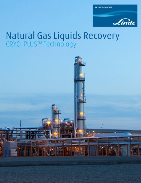
<strong>CRYO</strong>-<strong>PLUS</strong> TM Proprietary<br />
Technology<br />
Higher Recovery with Less Energy<br />
Designed to be used in natural gas, or shale gas<br />
applications, the patented <strong>CRYO</strong>-<strong>PLUS</strong> process<br />
recovers more ethane and heavier components with<br />
less energy required than traditional liquid recovery<br />
processes.<br />
Reduced Feed and Product Compression<br />
The proprietary process has been optimized to<br />
operate more efficiently resulting in lower inlet<br />
pressure requirements while still providing the same<br />
product discharge pressure.<br />
Higher Flexibility<br />
Enhanced <strong>CRYO</strong>-<strong>PLUS</strong> TM is more robust and flexible<br />
over a wide range of pressure and feed compositions.<br />
This feature is especially important for treatment<br />
of wet shale gas, which is known for having large<br />
compositional variability over time.<br />
<strong>CRYO</strong>-<strong>PLUS</strong> TM provides a high level of ethane recovery<br />
in ethane recovery mode, and a high level propane<br />
recovery in ethane rejection mode. The process can<br />
quickly and easily change between the two modes of<br />
operation.<br />
Reduced Fuel Consumption<br />
The <strong>CRYO</strong>-<strong>PLUS</strong> TM process requires less power than a<br />
typical gas processing plant.
04<br />
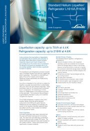
Figure 1<br />
STANDARD-<strong>PLUS</strong> TM<br />
Sales (Residue) <strong>Gas</strong><br />
Refrigeration<br />
FEED <strong>Gas</strong><br />
Inlet Slug<br />
Catchers<br />
Inlet <strong>Gas</strong><br />
Compression<br />
Amine Unit<br />
for C0 2<br />
& H 2<br />
S<br />
Removal<br />
Dehydration<br />
<strong>CRYO</strong>-<br />
<strong>PLUS</strong> TM<br />
Residue<br />
Compression<br />
To Fractionation<br />
C 2<br />
Product<br />
Optional Fractionation<br />
C 3<br />
Product<br />
iC 4<br />
Condensate<br />
Stabilizer<br />
Deethanizer Depropanizer Debutanizer<br />
LPG<br />
C 4<br />
Splitter<br />
C 4<br />
iC 4<br />
iC 4<br />
Isomerization<br />
Supplemental<br />
Refrigeration<br />
C 5<br />
+ Product<br />
<strong>CRYO</strong>-<strong>PLUS</strong> TM in <strong>Natural</strong> <strong>Gas</strong> <strong>Process</strong>ing<br />
<strong>CRYO</strong>-<strong>PLUS</strong> <br />
<strong>CRYO</strong>-<strong>PLUS</strong> improves recovery of C 2<br />
+ components, thus allowing gas<br />
processors to meet the heating value requirements for the gas while<br />
adding profits to the bottom line. The ethane and heavier hydrocarbons<br />
recovered become valuable feeds for crackers producing olefins and<br />
subsequentially for polyethylene and polypropylene plants.
05<br />
<strong>CRYO</strong>-<strong>PLUS</strong> <br />
To date, LPP has installed several <strong>CRYO</strong>-<strong>PLUS</strong><br />
Recovery Systems in <strong>Natural</strong> <strong>Gas</strong> <strong>Process</strong>ing Plants.<br />
The economic payout of these systems can be as low<br />
as one year. All of these systems were designed for<br />
recovery or rejection of ethane depending on the<br />
required mode of operation<br />
Where is <strong>CRYO</strong>-<strong>PLUS</strong> Used<br />
<strong>CRYO</strong>-<strong>PLUS</strong> TM is used for processing any type of gas<br />
containing hydrocarbon liquids. Traditionally, the<br />
gas processing industry have been using Dew Point<br />
Control or other technology plants to purify the natural<br />
gas to meet pipeline requirements, i.e. prevent liquids<br />
formation in pipeline and meet a maximum BTU content.<br />
Unfortunately, these systems recover less than 80%<br />
of the C 2<br />
and some of the C 3<br />
+ can slip through into the<br />
gas. These C 2<br />
+ liquids may provide for a higher sales<br />
value than the pipeline gas by itself. Figure 1 shows a<br />
block flow diagram for a typical natural gas processing<br />
scheme, and indicates where <strong>CRYO</strong>-<strong>PLUS</strong> is integrated<br />
within the operation.<br />
<strong>CRYO</strong>-<strong>PLUS</strong> Benefits<br />
The optimum C 2<br />
and C 3<br />
recoveries are a function of<br />
the relative values of the recovered components, the<br />
fuel gas, utilities, fit to available compression, and the<br />
required economic payout. <strong>CRYO</strong>-<strong>PLUS</strong> recovery for<br />
C 2<br />
is typically 96%, with essentially 100% recovery of<br />
C 3<br />
and heavier components when operated in ethane<br />
recovery mode. Corresponding recoveries for ethane<br />
rejection mode is 98% or greater for C 3<br />
, and 100% of<br />
the heavier components. Typical <strong>CRYO</strong>-<strong>PLUS</strong> feed<br />
and product compositions are indicated in Table 1A<br />
and Table 1B for the two modes of operation. The<br />
material balances are for a nominal 200 MMSCFD feed<br />
gas from a shale gas well. For example, assuming a<br />
natural gas fuel value of $3.75/M<strong>MB</strong>TU, this gas as<br />
fuel has a value of approximately $1,013,325/Day.<br />
When operating in ethane rejection mode as shown<br />
in Table 1A, the <strong>CRYO</strong>-<strong>PLUS</strong> technology recovers<br />
approximately 25,520 BBL/Day of mixed C 2<br />
+ liquids.<br />
If the average value of the C 2<br />
+ liquids is $0.57/<br />
gallon, then the combined value of the C 2<br />
+ liquids<br />
plus the residue gas as fuel is $1,276,317/Day.<br />
This differential results in a gross margin between<br />
the two operations of over $92,000,000 per year.<br />
These simplified calculations assume that the plant<br />
can sell the higher BTU natural gas stream without<br />
any treatment. This is normally not possible due<br />
to pipeline requirements, but it may be possible to<br />
do minimum treatment and disposing the liquids.<br />
When disposing the liquids or flaring this high BTU<br />
gas, these already impressive economics improve<br />
dramatically. (Substitute your own product values<br />
and see your impact.) The recovered liquid stream’s<br />
composition is a reflection of the fuel gas streams that<br />
comprise the <strong>CRYO</strong>-<strong>PLUS</strong> feeds. Alternatively, the<br />
C 2<br />
, C 3<br />
and C 4<br />
’s can be split by fractionation and each<br />
can be fed to a separate process for further upgrading<br />
or simply sold as chemical feedstock.<br />
The same economic calculations can be done for<br />
operation in ethane recovery mode as is shown in<br />
Table 1B. In this case, the <strong>CRYO</strong>-<strong>PLUS</strong> technology<br />
recovers approximately 35,630 BBL/Day of mixed C 2<br />
+<br />
liquids. Due to a higher ethane content, the average<br />
value of this mix may be lower so if $0.44/gallon<br />
is used instead, then the combined value of the C 2<br />
+<br />
liquids plus the residue gas as fuel is $1,210,029/Day.<br />
The differential this time results in a gross margin<br />
between the two operations of over $68,800,000 per<br />
year, which is still an attractive return.<br />
A subtle, but very real additional benefit of<br />
<strong>CRYO</strong>-<strong>PLUS</strong> derives from the change in the fuel<br />
gas composition after removing the C 3<br />
and C 4<br />
components. The higher heating value of the C 3<br />
and<br />
C 4<br />
’s results in a higher flame temperature within<br />
the furnace or boiler; this may result in higher NO x<br />
emissions. Removal of C 3<br />
and C 4<br />
components from the<br />
fuel gas therefore achieves a measurable reduction<br />
in NO x<br />
emissions. This incremental reduction may be<br />
enough to keep the end-user of the gas in compliance<br />
and avoid expensive NO x<br />
reduction modifications for<br />
the combustion processes.
06<br />
Table 1-A Typical Propane Recovery<br />
(ethane rejection mode)<br />
N 2<br />
Component<br />
CO 2<br />
C 1<br />
C 2<br />
C 3<br />
iC 4<br />
NC 4<br />
iC 5<br />
NC 5<br />
C 5<br />
+<br />
H 2<br />
O<br />
Totals<br />
Mol/Hr<br />
Lb/Hr<br />
MMSCFD<br />
BBL/day<br />
M<strong>MB</strong>TU/hr<br />
Avg. MolWt<br />
BTU/SCF<br />
Feed<br />
Mol/Hr<br />
267<br />
11<br />
15,562<br />
3,479<br />
1,492<br />
228<br />
412<br />
112<br />
103<br />
150<br />
21,816<br />
493,662<br />
200<br />
11,259<br />
22.63<br />
1,351<br />
Residue <strong>Gas</strong><br />
Mol/Hr<br />
267<br />
10<br />
15,530<br />
2,057<br />
28<br />
17,892<br />
320,173<br />
163<br />
7,396<br />
17.89<br />
1,089<br />
Liquid Product<br />
Mol/Hr<br />
1<br />
31<br />
1,421<br />
1,465<br />
228<br />
412<br />
112<br />
103<br />
150<br />
3,923<br />
173,488<br />
36<br />
25,520<br />
3,835<br />
44.22<br />
2,576<br />
*Ethane recovery is governed by the residue gas heating value<br />
Recovery<br />
%<br />
41<br />
98<br />
100<br />
100<br />
100<br />
100<br />
100<br />
*<br />
N 2<br />
Table 1-B Typical Ethane Plus Recovery<br />
Component<br />
CO 2<br />
C 1<br />
C 2<br />
C 3<br />
iC 4<br />
NC 4<br />
iC 5<br />
NC 5<br />
C 5<br />
+<br />
H 2<br />
O<br />
Totals<br />
Mol/Hr<br />
Lb/Hr<br />
MMSCFD<br />
BBL/day<br />
M<strong>MB</strong>TU/hr<br />
Avg. MolWt<br />
BTU/SCF<br />
Feed<br />
Mol/Hr<br />
267<br />
11<br />
15,562<br />
3,479<br />
1,492<br />
228<br />
412<br />
112<br />
103<br />
150<br />
21,816<br />
493,662<br />
200<br />
11,259<br />
22.63<br />
1,351<br />
Residue <strong>Gas</strong><br />
Mol/Hr<br />
Plant modules are workshop prefabricated to maximum extent<br />
267<br />
5<br />
15,515<br />
129<br />
15,916<br />
260,510<br />
145<br />
6,060<br />
16.37<br />
1,003<br />
Liquid Product<br />
Mol/Hr<br />
6<br />
47<br />
3,349<br />
1,492<br />
228<br />
412<br />
112<br />
103<br />
150<br />
5,899<br />
233,155<br />
54<br />
35,630<br />
5,168<br />
39.52<br />
2,309<br />
Recovery<br />
%<br />
96<br />
100<br />
100<br />
100<br />
100<br />
100<br />
100<br />
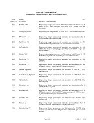
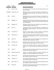
120 & 200 MMSCFD<br />
Cryogenic <strong>Natural</strong> <strong>Gas</strong><br />
Plant<br />
20 MMSCFD Cryogenic<br />
<strong>Natural</strong> <strong>Gas</strong> Plant<br />
100 MMSCFD <strong>CRYO</strong>-<strong>PLUS</strong> TM<br />
<strong>Natural</strong> <strong>Gas</strong> Plant<br />
120 MMSCFD Cryogenic<br />
<strong>Natural</strong> <strong>Gas</strong> Plant<br />
450 MMSCFD Cryogenic<br />
<strong>Natural</strong> <strong>Gas</strong> Plant<br />
350 MMSCFD Cryogenic<br />
<strong>Natural</strong> <strong>Gas</strong> Plant<br />
Plant is essentially fully modular<br />
1974 1988 2000 2009 2012
07<br />
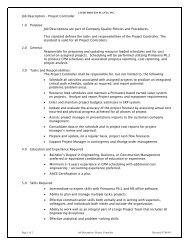
How <strong>CRYO</strong> <strong>PLUS</strong> <strong>Process</strong>es Work<br />
<strong>CRYO</strong>-<strong>PLUS</strong> is a cryogenic recovery technology<br />
which utilizes a turbo-expander to recover energy<br />
while cooling the feed gas. <strong>CRYO</strong>-<strong>PLUS</strong> technology<br />
is unique in its ability to process low-pressure<br />
gas streams and obtain high recoveries with less<br />
compressor and/or refrigeration horsepower than<br />
conventional or competing cryogenic processes. A<br />
description of the unit operations follows. Figure 2 is<br />
a block flow of <strong>CRYO</strong>-<strong>PLUS</strong> processing.<br />
Feed Conditioning<br />
To protect the unit against upset conditions, feeds<br />
may first pass through a coalescing filter/separator<br />
designed to remove solid particles and liquid droplets<br />
that may carry over from upstream processes.<br />
Although <strong>CRYO</strong>-<strong>PLUS</strong> can tolerate small quantities of<br />
H 2<br />
S and CO 2<br />
these compounds are not desirable. The<br />
use of an amine treating unit for removal of acid gas<br />
components removes these compounds in an absorption<br />
process as a feed conditioning step<br />
Figure 2<br />
Feed Conditioning:<br />
- Particulate Removal<br />
- Liquids Separation<br />
- Acid <strong>Gas</strong> Removal<br />
- Other Treatment<br />
Compression<br />
And<br />
Dehydration<br />
Cooling:<br />
- Heat Exchange<br />
- Refrigeration<br />
Dry Conditioned Fuel <strong>Gas</strong><br />
C 2<br />
Recovery:<br />
- Turboexpansion<br />
- Fractionation<br />
Additional<br />
Fractionation:<br />
- Deethanizing<br />
- Depropanizing<br />
- Debutanizing<br />
- Deisobutanizing<br />
C 3<br />
C 4 ‘s<br />
C 5 ‘s<br />
Upgrading<br />
<strong>Process</strong>es:<br />
- Chemical Feedstock<br />
- Isomerization<br />
- Polymerization<br />
- Alkylation<br />
- <strong>Gas</strong>oline Blending<br />
Block Flow Diagram of <strong>CRYO</strong>-<strong>PLUS</strong> <strong>Process</strong>ing
08<br />
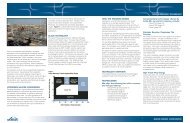
Figure 3<br />
From the Dehydration<br />
Regeneration System<br />
<strong>CRYO</strong>-<strong>PLUS</strong> RECOVERY<br />
Residue<br />
<strong>Gas</strong> to<br />
Fuel<br />
To the Dehydration<br />
Regeneration System<br />
Expander<br />
Compressor<br />
Inlet Heat<br />
Exchange<br />
Inlet <strong>Gas</strong> from Dehydration<br />
C3<br />
Cold<br />
Separator<br />
First<br />
Fractionator<br />
Second<br />
Fractionator<br />
Liquid Product<br />
Schematic of the <strong>CRYO</strong>-<strong>PLUS</strong> TM Recovery <strong>Process</strong><br />
C 2<br />
Recovery Comparison<br />
Typical NGL Plant<br />
95<br />
95<br />
<strong>CRYO</strong>-<strong>PLUS</strong> TM 90-95<br />
90<br />
90<br />
85<br />
85<br />
80<br />
75<br />
C 2 Recovery % 70<br />
65<br />
60<br />
90-95<br />
85-90<br />
80-85<br />
75-80<br />
70-75<br />
65-70<br />
60-65<br />
55-60<br />
50-55<br />
C 2 Recovery %<br />
80<br />
75<br />
70<br />
65<br />
60<br />
85-90<br />
80-85<br />
75-80<br />
70-75<br />
65-70<br />
60-65<br />
55-60<br />
50-55<br />
55<br />
55<br />
50<br />
50<br />
980<br />
780<br />
Inlet Pressure, psia<br />
580<br />
10.905<br />
5.076<br />
2.042<br />
Inlet <strong>Gas</strong> GPM<br />
980<br />
780<br />
Inlet Pressure, psia<br />
580<br />
10.905<br />
5.076<br />
2.042<br />
Inlet <strong>Gas</strong> GPM<br />
- Enhanced <strong>CRYO</strong>-<strong>PLUS</strong> TM provides a higher recovery over a wider range of pressure and composition.<br />
- Enhanced <strong>CRYO</strong>-<strong>PLUS</strong> TM provides 95% C 2<br />
recovery for 4.0 to 7.7 GPM natural gas.
09<br />
Feed Compression<br />
The next step is to compress the feed stream unless<br />
it is already at elevated pressures. An air cooler<br />
or cooling water, cools the gas downstream of the<br />
compressor to remove the heat of compression.<br />
(Heat of compression can also be used as a heat<br />
source for fractionation as permitted by the process<br />
heat balance and temperature driving force.)<br />
Dehydration<br />
To avoid ice and hydrate formation in the cryogenic<br />
section of the process, the water content of the gas<br />
is reduced to an acceptable level through adsorption<br />
in molecular sieve desiccant beds. This is a batch<br />
process, where multiple (two or more) adsorption<br />
beds are used. One or more of the adsorption beds<br />
are being regenerated to restore their capacity while<br />
the other bed(s) are on-line and drying the feed gas.<br />
A recycle portion of the dry gas can be heated and<br />
used for regeneration of the beds to drive off the<br />
adsorbed water. Cooling of this stream condenses<br />
the removed water, before it recycles and combines<br />
with the feed gas. A portion of the residue gas may<br />
also be used for the regeneration on a once through<br />
basis. Downstream of the adsorption beds, the gas<br />
passes through a dust filter to remove any particulate<br />
carryover before subsequent processing.<br />
Feed Cooling<br />
After dehydration, the feed gas flows into the cold<br />
section of the process, where cooling by exchange of<br />
heat with the residue gas and cold separator liquids<br />
takes place using a brazed aluminum plate-fin heat<br />
exchanger. Although not always a requirement, the<br />
gas may be further cooled using external refrigeration<br />
before it goes to the cryogenic portion of the<br />
process.<br />
Cold Separation<br />
Following cooling, the feed gas is partially condensed<br />
and delivered to a vapor/liquid separator. The liquid<br />
then flows through the inlet exchanger to cool the<br />
feed gas before entering the deethanizer for fractionation.<br />
The vapor flows to the inlet of the expander/<br />
compressor. As the gas expands, it provides the<br />
work/energy for the compression. The expansion<br />
and removal of energy cools the gas further and<br />
causes additional condensation. The expander<br />
discharges into the first tower of a two-stage fractionation<br />
process. The configuration and the combination<br />
of fractionation and heat transfer between these two<br />
columns is the proprietary, patented technology that<br />
gives <strong>CRYO</strong>-<strong>PLUS</strong> its advantages (higher recovery at<br />
reduced horsepower) over competing technologies.<br />
A residue gas and a deethanized liquid product are<br />
produced from this two tower scheme. The residue<br />
gas is at or near the fuel system pressure. Following<br />
exchange with the feed gas in the inlet cooling step,<br />
it arrives at the fuel system as a dry, stable heating<br />
value fuel. The liquid product from the fractionation<br />
system is the recovered C 2<br />
or C 3<br />
liquid hydrocarbons.<br />
The liquid often undergoes additional processing,<br />
such as additional fractionation in downstream<br />
columns. For C 3<br />
recovery, the liquid stream is normally<br />
debutanized. The C 3<br />
and C 4<br />
’s may then be fed to<br />
an alkylation process, or split with the C 3<br />
going to<br />
isomerization/polymerization and only the C 4<br />
’s going<br />
to isomerization/alkylation feed. For C 3<br />
recovery, a<br />
depropanizer normally precedes the debutanizer.
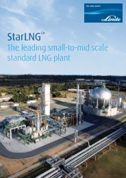
Customized Design<br />
LPP specifically designs and fabricates unique<br />
modules to optimize the site layout and fit the<br />
available space. A growing number of gas processing<br />
companies have come to recognize the benefits of<br />
modular fabrication over traditional field fabricated<br />
process systems. Besides the traditional focus on<br />
lower initial cost, modular fabrication results in many<br />
other operational and maintenance advantages.<br />
Modular fabrication results in streamlined project<br />
execution, a predictable schedule, low cost, and<br />
minimizes the risk of construction within an operating<br />
plant.<br />
Modular Construction<br />
The gas processing industry recognizes the challenges<br />
of conventional on-site construction. Modularization<br />
will minimize the on-site construction time and<br />
thereby reduce cost and schedule of the overall<br />
project.<br />
Shorter Project Schedule<br />
With field fabrication, workers are at the mercy of the<br />
environment. Schedule and quality often suffers under<br />
adverse weather conditions. LPP’s skilled and stable<br />
work force performs their work in the controlled<br />
environment of one of the finest fabrication facilities<br />
in the US, maintaining schedule regardless of weather<br />
conditions with ISO-9001 quality.<br />
Safer to Construct Away from<br />
Hazardous <strong>Process</strong>es<br />
On-site construction alongside operational equipment<br />
carrying high-pressure hydrocarbons increases<br />
on-site construction risk. LPP performs fabrication in<br />
the safety of a controlled environment without the<br />
risk of plant upsets or construction worker’s errors,<br />
and then transports the completed prefabricated and<br />
preassembled system to the , where a small crew<br />
quickly installs them, thus minimizing risk.<br />
Less Downtime<br />
The cost of downtime associated with construction<br />
can add significantly to the overall cost of construction.<br />
LPP is minimizing downtime by building units<br />
off-site.
11<br />
About LPP<br />
LPP is a company with over forty years’ experience in<br />
refining, petrochemicals and natural gas processing.<br />
As a subsidiary of The <strong>Linde</strong> Group, we are a totally<br />
integrated technology, engineering, fabrication, and<br />
construction company.<br />
Engineering<br />
Engineers are available with all of the disciplines<br />
required to provide turnkey plant installations using<br />
proprietary technology or the client’s design.<br />
Fabrication<br />
LPP is a leader in the field of engineering and fabrication<br />
of turnkey process systems. In addition to road<br />
and rail transportation, our fabrication facilities have<br />
access to the Port of Catoosa on the Arkansas River,<br />
which can transport prefabricated modules on oceangoing<br />
barges to global markets via the Port of New<br />
Orleans.<br />
Technology<br />
Either proprietary LPP or licensed technology is used.<br />
With LPP’s Experience and Resources You<br />
are Assured Success<br />
Only <strong>Linde</strong> <strong>Process</strong> Plants, Inc. has the combination of<br />
proprietary technologies, proven experience, specialized<br />
skills, impressive record of accomplishment, and<br />
certified fabrication facilities to deliver major turnkey<br />
process plants to global markets successfully.<br />
<strong>Process</strong>es Offered by LPP<br />
- <strong>CRYO</strong>-<strong>PLUS</strong> , Recovers C 3<br />
+<br />
- <strong>CRYO</strong>-<strong>PLUS</strong> C2= , Recovers C 2<br />
+<br />
- Sulfur Recovery<br />
- <strong>Natural</strong> <strong>Gas</strong> <strong>Process</strong>ing<br />
- Nitrogen Rejection<br />
- Helium/Hydrogen Liquefiers
<strong>Linde</strong> <strong>Process</strong> Plants, Inc.<br />
A member of The <strong>Linde</strong> Group<br />
6100 South Yale Avenue, Suite 1200, Tulsa, Oklahoma 74136, USA<br />
Phone: +1.918.477.1200, Fax: +1.918.477.1100, www.LPPUSA.com, e-mail: sales@LPPUSA.com