Untitled - National Roofing Contractors Association
Untitled - National Roofing Contractors Association
Untitled - National Roofing Contractors Association

You also want an ePaper? Increase the reach of your titles
YUMPU automatically turns print PDFs into web optimized ePapers that Google loves.
Coal-tar roofing products are described by ASTM Standard<br />
0-450, Types I & III, "Coal Tar Pitch Used in <strong>Roofing</strong>,<br />
Dampproofing and Waterproofing." Types I & "' are<br />
suitable for use in the construction of coal tar built-up<br />
roofing, the difference being that Type III has less volatile<br />
components than Type I. The Equiviscous Temperature<br />
(EVT) concept is equaJly applicable to coal tar<br />
products, although the recommended viscosity base is<br />
considerabfy lower for the coal tar products than for roofing<br />
asphalts. In the event the information is not furnished<br />
by the supplier, the following temperature ranges appear<br />
to be appropriate for coal tar for ~h mechanicaJ spreader<br />
and mopping application techniques:<br />
. Coal Tar Pitch (Type I) approximately 360 F plus<br />
or minus 25 F<br />
. Coal Tar Bitumen (Type III) approximately 375 F<br />
plus or minus 25 F<br />
XXI. WATER CUTOFFS AND<br />
WEATHER PROTECTION<br />
Water cutoffs are temporary felt courses that are installed<br />
to prevent moisture from entering the insulation and<br />
membrane during construction. They should be applied<br />
at the end of each day's work and whenever work is halted<br />
for an indefinite period to protect the membrane from<br />
precipitation. They must be removed prior to installing<br />
additional insulation.<br />
Temporary flashings should be installed as weather protection<br />
If permanent flashings are not in place. All openings<br />
in the membrane should be sealed to prevent any<br />
moisture from entering the roof system before completing<br />
membrane application.<br />
Specifications requiring gravel installation each day are<br />
unrealistic and sometimes detrimental to the quality of<br />
the completed roof. Where working conditions permit,<br />
roofing felts should be "glazed" and sealed at the end<br />
of each day's work if final surfacing is not installed.<br />
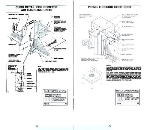
The most vulnerable part of any roof system is that point<br />
at which the horizontal roof deck and a vertical surface<br />
join. Most roof leaks occur at these flashing locations.<br />
The designers should carefully consider the design of<br />
flashing details at these locations. (See NRCA Construction<br />
Details in the NRCA <strong>Roofing</strong> and Waterproofing<br />
Manua/.)<br />
The term flashing can be divided into two groups:<br />
1. Composition Flashing (Base Flashing)<br />
The bending radius of present composition roofing<br />
materials is generally limited to 45 degrees. To allow<br />
for this bending radius, all vertical surfaces must<br />
have cant strips installed between the roof and the<br />
vertical surface. The height of the base flashing<br />
should be not lower than (a nominal) 8 inches and<br />
not higher than (a nominal) 14 inches above the<br />
finished roof surface. Walls requiring flashings<br />
higher than 14 inches should receive special<br />
moisture-proofing. A wood nailer strip or suitable detail<br />
allowing mechanical fastening of the base flashing<br />
at the top must be provided. Masonry surfaces<br />
should be primed with asphalt concrete primer.<br />
Expansion joint flashings (allowing expansion and<br />
contraction) should be constructed as detailed in the<br />
NRCA Construction Details. The wood curbing<br />
should be placed against the wall and secured only<br />
to the deck. The designer is cautioned to consider<br />
that building components are subjected to thermal<br />
movements at different rates and in different directions<br />
from the roof membrane. If the roof is to be tied<br />
into these components, special consideration should<br />
be given to the design of that juncture.<br />
2. Metal Flashing (Counterflashlng and Cap<br />
Flashing)<br />
Since metals have a high coefficient of expansion.<br />
metal flashing must be isolated from the roof mem-<br />
36 37

![Wm] - National Roofing Contractors Association](https://img.yumpu.com/36696816/1/190x245/wm-national-roofing-contractors-association.jpg?quality=85)