2-Wire Bus System - FAST Spec
2-Wire Bus System - FAST Spec
2-Wire Bus System - FAST Spec

Create successful ePaper yourself
Turn your PDF publications into a flip-book with our unique Google optimized e-Paper software.
Planning Manual<br />
Siedle In-Home bus<br />
Issue 2006
Contents<br />
Siedle In-Home bus 3<br />
Fields of application, performance features 4<br />
In-Home bus components and users 5<br />
Siedle In-Home bus general<br />
Procedure during planning 7<br />
Siedle In-Home bus: Audio<br />
Cable size diagram<br />
Single line system up to max. 31 users 8<br />
Cable size diagram<br />
Multiple line system up to max. 465 users 9<br />
Remarks relating to installation<br />
Range 10<br />
Siedle In-Home bus: Video 12<br />
Cable size diagram<br />
Single line system up to max. 31 users 13<br />
Cable size diagram<br />
Multiple line system up to max. 465 users 14<br />
Installation remarks<br />
Range<br />
Attenuation values 15-18<br />
Example<br />
of attenuation calculation 19<br />
Storey door station<br />
at the Siedle In-Home bus: Audio 20<br />
Storey door station with video<br />
at the In-Home bus: Video 20<br />
Switching and control functions<br />
at the Siedle In-Home bus 21<br />
Siedle In-Home bus combined with<br />
the Vario bus<br />
Input modules<br />
Ranges in the Vario bus 22<br />
Device description<br />
Door area audio<br />
- Siedle Vario<br />
- Siedle custom-fit door loudspeaker<br />
- Siedle Classic 23-24<br />
Door area<br />
Video components 25-26<br />
<strong>Bus</strong> telephones, DoorCom 27-29<br />
<strong>Bus</strong> telephones with colour monitor, accessories 30<br />
<strong>Bus</strong> secondary signal unit 31<br />
In-Home bus power supply 32<br />
Switching and control devices, bus distributor 33<br />
Vario bus switching and control devices<br />
Information on programming 34<br />
For complex systems or special<br />
requirements, the technical<br />
consultants in our centers will<br />
be pleased to advise you.<br />
Technical additions<br />
! or printing errors do not<br />
constitute grounds for<br />
compensation claims.
Siedle In-Home bus<br />
The Siedle In-Home bus is a<br />
high-performance<br />
communication system with a<br />
wide range of performance<br />
features which is simple to set<br />
up.<br />
The basic functions calling,<br />
speech, door release and light<br />
switching are supplemented by<br />
video and control functions.<br />
Interfaces to the telephone<br />
network are available with the<br />
DoorCom family for analogue<br />
and ISDN connection.<br />
From small-scale systems in the<br />
sophisticated single family<br />
home through multiple family<br />
homes to large residential<br />
complexes, the Siedle In-Home<br />
bus is in popular use as a<br />
communication and control<br />
system.<br />
The entire range of functional<br />
features is available if just 2<br />
adjacent YR wires are available<br />
throughout the system.<br />
For newly installed systems, we<br />
recommend using standard<br />
commercially available<br />
conductor material J-Y(ST)Y.<br />
Every user connected to the In-<br />
Home bus is able to fulfill its<br />
intended function<br />
independently where it is<br />
installed.<br />
The functions can be modified<br />
and adjusted by programming.<br />
In-Home:<br />
Audio as a single-line system<br />
In-Home:<br />
Audio as a multiple-line system<br />
3
Siedle In-Home bus<br />
Application range<br />
Performance features<br />
The only requirement for use of<br />
the Siedle In-Home bus are 2<br />
continuous YR or J-Y(St)Y<br />
cores, via which the entire<br />
range of functions including<br />
audio and video<br />
communication can be<br />
performed.<br />
The Siedle In-Home bus is used<br />
• in sophisticated one and twofamily<br />
homes which seek a<br />
greater level of operating<br />
convenience using the<br />
increasingly accessible technical<br />
possibilities available<br />
• in multiple family homes and<br />
larger residential complexes<br />
offering an enhanced level of<br />
security<br />
• and in private and<br />
commercial properties in which<br />
additional control and<br />
switching functions are<br />
required<br />
Performance features<br />
Calling/Speech/Door release/<br />
Audio privacy function<br />
Storey call with call differentiation<br />
Light control<br />
Secondary signal unit<br />
Door release time<br />
No. of door stations<br />
Siedle In-Home bus<br />
with BTS/BTC/BTSV/BTCV 850-...<br />
•<br />
without additional installation<br />
via BNS 750-..., standard<br />
commercially available signal unit via<br />
BSM/BSE 650-... or ZAR 850-...,<br />
additional installation required<br />
fixed at 3 secs<br />
Number of lines max. 15<br />
Number of users per line max. 31<br />
Total number of users max. 465<br />
Speech circuits<br />
Call silencing with<br />
LED display<br />
Call volume regulation<br />
in 5 stages<br />
within the system limits<br />
optional number<br />
1 per line<br />
•<br />
•<br />
Video link via BTSV/BTCV 850-...<br />
Performance features<br />
Door parallel call<br />
extendable to 8 devices<br />
with additional power supply<br />
Siedle In-Home bus<br />
with BTS/BTC/BTSV/BTCV 850-...<br />
• up to 4 users<br />
BTC/BTSV/BTCV<br />
(BTC only with ZPS 850-...)<br />
Doormatic function BTC/BTCV 850-...<br />
Call forwarding BTC/BTCV 850-...<br />
Programming<br />
Plug+Play programming<br />
exclusively using the devices of<br />
series:<br />
• BTS/BTC/BTSV/BTCV 850-...,<br />
• BNG/BVNG 650-... and<br />
• BTLM 650-03 with<br />
BTM 650-01 to BTM 650-04<br />
or<br />
• BTLE 050-03 with<br />
BRMA 050-01<br />
manual, Plug+Play*<br />
or via PC<br />
When using in a mixed<br />
installation with predecessor<br />
models, Plug+Play<br />
programming is not possible.<br />
Applies for the assignment of<br />
call stations to call buttons.<br />
Extensions to the basic<br />
functions, for example parallel<br />
call or switching and control<br />
functions, are additionally<br />
programmed manually or by<br />
PC.<br />
Storey call loudspeaker with<br />
call differentiation<br />
Internal communication including<br />
call progress tones<br />
Switching/control function<br />
•<br />
•<br />
•<br />
Display LEDs under the buttons • BTC/BTCV 850-...<br />
Direct selective door dialling including<br />
Video actuation • BTSV/BTCV 850-...<br />
Digital call input possible (COM/DRM)<br />
• BIM 650-... required
Components<br />
Area Components Users<br />
Interface to the telephone network<br />
Door area<br />
BTLM/<br />
SBTLM 650-... <strong>Bus</strong> door loudspeaker module 2<br />
BCMC 650-... <strong>Bus</strong> colour CCD camera module -<br />
BTLE 050-... <strong>Bus</strong>-custom-fit door loudspeaker 2<br />
Area Components Users<br />
DCA 650-... DoorCom Analog 1–31 (address dependent)<br />
DCI 650-... DoorCom ISDN 1–31 (address dependent)<br />
CL 01 B-01 Classic door station bus 2<br />
BTM 650-... <strong>Bus</strong> call button module -<br />
BRMA 050-... <strong>Bus</strong> call button matrix -<br />
BVA 650-... <strong>Bus</strong> video interfacing module 2<br />
BVS 650-... <strong>Bus</strong> video transmitter -<br />
Living area BTS 850-... Standard bus telephone 1<br />
BTC 850-... Deluxe bus telephone 1<br />
BNS 750-... <strong>Bus</strong> secondary signal unit 1<br />
BTSV 850-... Standard bus telephone video 1<br />
BTCV 850-... Deluxe bus telephone video 1<br />
Distribution BNG 650-... <strong>Bus</strong> line rectifier (for audio) -<br />
ZBVG 650-... <strong>Bus</strong> supply unit accessory -<br />
BVNG 650-... <strong>Bus</strong> video line rectifier -<br />
ZBVNG 650-... <strong>Bus</strong> video line rectifier accessory -<br />
The components can be linked<br />
to form a system both over a<br />
single-line system and a<br />
multiple-line system. The<br />
difference between the systems<br />
lies in the upgrade capability<br />
and the performance scope of<br />
the lines:<br />
• Single line systems are<br />
restricted to 31 users.<br />
• Multiple line systems can<br />
accommodate up to 15 lines<br />
with 31 users each, i.e. up to<br />
465 users. In additional, if<br />
programmed accordingly<br />
internal calls are also possible<br />
within one line.<br />
For more information, see the<br />
following page.<br />
The terms „user“<br />
! and „component“ or<br />
„device“ do not mean the<br />
same thing. Depending on its<br />
function, a component uses a<br />
certain bandwidth within the<br />
bus system can therefore count<br />
as 0, 1 or 2 users. The upgrade<br />
capability of the lines always<br />
refers to the number of users<br />
and not to the number of<br />
connected components or<br />
devices.<br />
BAA 650-... <strong>Bus</strong> audio decoupler -<br />
BVVU 650-... <strong>Bus</strong> video distributor asymmetrical -<br />
BVVS 650-... <strong>Bus</strong> video distributor symmetrical -<br />
BSM 650-... <strong>Bus</strong> switching module 1<br />
BIM 650-... <strong>Bus</strong> interface module -<br />
BSE 650-... <strong>Bus</strong> switching unit 1<br />
BEM 650-... <strong>Bus</strong> input module 1<br />
5
Siedle In-Home bus<br />
General<br />
Structure of the conductor<br />
network<br />
The Siedle In-Home bus can be<br />
structured as a single line or a<br />
multiple line system. The<br />
installation can be looped<br />
through from device to device<br />
or structured via a side circuit<br />
with bus distributor. Mixed<br />
structures are also possible.<br />
Single line system<br />
<strong>System</strong>s with up to 31 users<br />
with one speech channel.<br />
The basic functions calling,<br />
speech, door release and light<br />
switching to the front door are<br />
performed as a matter of<br />
course, with several doors.<br />
In addition, there are a many<br />
different performance features<br />
available.<br />
Several speech channels or a<br />
higher number of users call for<br />
a multiple line system.<br />
Parallel call<br />
A call button can be assigned<br />
to several bus telephones in<br />
parallel. If the call button is<br />
pressed, these ring at the same<br />
time. The bus telephone which<br />
is lifted first is connected to the<br />
caller.<br />
Internal speech operation<br />
The users can<br />
intercommunicate internally<br />
provided the devices have been<br />
programmed accordingly.<br />
Interface to the telephone<br />
network<br />
Instead of a user, an analog or<br />
ISDN interface can be<br />
connected to link up to the<br />
telephone network. The<br />
DoorCom Analog DCA 650-...<br />
or DoorCom ISDN DCI 600-...<br />
can be used to create this link.<br />
Switching and control<br />
elements for greater<br />
convenience<br />
In the central sub-distributor or<br />
at any optional location in the<br />
line bus switching modules<br />
BSE 650-..., BEM 650-... and<br />
BSM 650-... can be installed<br />
and actuated by authorized<br />
users. e.g. for staircase lighting<br />
in addition to the external<br />
lighting or all-round lighting.<br />
At any optional position of the<br />
In-Home bus, switching and<br />
control elements BSM/BSE/<br />
BEM 650-... can be installed for<br />
selective actuation of individual<br />
or several users. (e.g. for roller<br />
blind actuation)<br />
Programming is described in<br />
the system manual enclosed<br />
with the BNG/BVNG 650-... ,<br />
and can be performed<br />
manually, using Plug+Play or<br />
via a PC.<br />
Plug+Play programming refers<br />
exclusively to the assignment of<br />
bus telephones to call buttons.<br />
For programming with the PC,<br />
the interface PRI 602-USB with<br />
software BPS 650-... from<br />
V 2.00 is required.<br />
When programming using the<br />
PC, access rights to status<br />
displays or control functions<br />
are defined for the individual<br />
users.<br />
Multiple line system<br />
In contrast to the single line<br />
system, in multiple line systems<br />
installations can be formed<br />
encompassing up to 465 users.<br />
At first glance, the only<br />
difference in the performance<br />
features available appears to be<br />
the maximum number of users.<br />
However, a significant<br />
difference exists in terms of the<br />
number of speech channels.<br />
One speech channel is available<br />
per line.<br />
In multiple line systems, it is<br />
possible for a bus telephone to<br />
communicate e.g. with the<br />
door station and at the same<br />
time bus telephones on a<br />
different line to communicate<br />
internally via another speech<br />
circuit.<br />
In single line systems, only one<br />
speech channel is ever possible.<br />
Several speech channels<br />
BTS/BTC 850-... or BTSV/<br />
BTCV 850-... connected to one<br />
line can communicate<br />
internally. If the system is<br />
configured with several lines, in<br />
each line a call can be held<br />
without mutual interference.<br />
No internal calls are possible<br />
across different lines.<br />
There is only ever one speech<br />
channel available to the shared<br />
entrance door, even if several<br />
doors are completely or<br />
partially shared.<br />
An example of a multiple line<br />
system:<br />
A project accommodates<br />
several independent bureaus or<br />
practices.<br />
The entrances are jointly used<br />
and internal communication is<br />
also required.<br />
Storey door loudspeaker<br />
Can be installed instead of a<br />
storey call button. All that is<br />
required in addition is a 12 V<br />
AC supply for the door release.<br />
Status display for important<br />
information<br />
At the deluxe devices BTC/<br />
BTCV 850-..., status messages<br />
can be displayed which are<br />
transmitted by a bus input<br />
module BEM 650-... or by a<br />
switching module BSE 650-...<br />
(e.g. garage door open, terrace<br />
door open or fault in the air<br />
conditioning unit).
Procedure during<br />
planning<br />
Even extensive and complex<br />
Siedle In-Home bus systems are<br />
simple to plan. In drawing up<br />
the planning documentation,<br />
we have used a systematic<br />
approach which applies<br />
throughout the entire planning<br />
process.<br />
We consider the most logical<br />
procedure is to start with<br />
planning the door area then<br />
to work on the living area and<br />
to finish with the distribution.<br />
Distribution encompasses not<br />
only the power supply to the<br />
devices but also any switching<br />
and control functions.<br />
In each area, i.e. door, living<br />
area and distribution, first the<br />
audio and then the video<br />
components are described.<br />
In the Siedle In-Home bus, the<br />
audio, video and control signals<br />
are transmitted via two cores<br />
routed side by side.<br />
General<br />
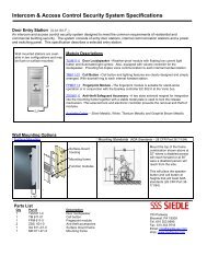
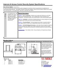
The design of the door area<br />
can differ considerably. For<br />
standard applications, the door<br />
area design is simple to put<br />
together using the Siedle<br />
purchase order catalogue.<br />
The planning documents refer<br />
exclusively to the electrical<br />
components required to ensure<br />
that the system functions<br />
reliably.<br />
Additional functions and<br />
design elements have to be<br />
taken into consideration during<br />
planning and subsequently at<br />
the installation stage.<br />
When planning the door<br />
station, pay attention to the<br />
mounting height, in particular<br />
when a video camera is being<br />
used.<br />
Recommended mounting<br />
height appr. 1.60 m to<br />
centre camera<br />
Door area<br />
The door area offers wide<br />
scope for creative design.<br />
The door station can be<br />
equipped, for instance, with:<br />
• Siedle Vario,<br />
• Siedle Classic<br />
• Siedle Steel or<br />
• Siedle custom-fit door<br />
loudspeaker for mounting in an<br />
existing intercom<br />
compartment.<br />
7
In-Home bus: Audio<br />
Single line system up to max. 31 users<br />
Cable size diagram<br />
ÜV-THa-1/1<br />
Speech connection to the door<br />
station via the BTS/BTC 850-...<br />
in a single or multiple family<br />
home.<br />
In conjunction with the<br />
BTS/BTC 850-... also for<br />
internal telephony and/or for<br />
control functions in<br />
sophisticated single or multiple<br />
family homes where an<br />
advanced level of convenience<br />
is required.<br />
Where the execution of<br />
i other control functions is<br />
required alongside door release<br />
and control functions using the<br />
BTC 850-... , the bus switching<br />
module BSM 650-... or bus<br />
switching unit BSE 650-... is<br />
required in addition.<br />
See switching/control functions<br />
Page 21 and 34<br />
Mode of operation<br />
Call, speech, door release and<br />
light operation between the<br />
door stations and the<br />
connected BTS/BTC 850-...<br />
units.<br />
Internal speech communication<br />
from bus telephone to bus<br />
telephone is possible within<br />
one line.<br />
Third party audio privacy<br />
function.<br />
For bus telephones BTS 850-...<br />
there are 10 and for the<br />
BTC 850-... 11 different ring<br />
tones to choose from. Call<br />
differentiation between door<br />
calls, storey calls and internal<br />
calls is freely selectable.<br />
Call silencing with status<br />
display and optical call display<br />
integrated.<br />
Door release actuation at the<br />
door station which placed the<br />
last call and light actuation are<br />
possible at any time.<br />
Door release actuation time:<br />
Fixed at 3 secs.<br />
Light contact actuation time:<br />
0.4 secs with BPS 650-... , can<br />
be changed from V 2.00<br />
ERT: Storey call button<br />
Installation can be<br />
performed from bus<br />
telephone to bus telephone<br />
or via a bus distributor.<br />
Mixed installation is also<br />
possible.<br />
Key<br />
ERT = Storey call button<br />
Tö = Door release<br />
(12 V AC min. 20 Ohm)
In-Home bus: Audio<br />
Multiple line system up to max. 465 users<br />
Cable size diagram<br />
ÜV-THa-n/n<br />
Speech connection to the door<br />
station via the BTS/BTC 850-...<br />
in residential complexes.<br />
In conjunction with the<br />
BTC 850-... additional control<br />
functions and also internal<br />
telephony within one and the<br />
same line are possible.<br />
Where the execution of<br />
i other control functions is<br />
required alongside door release<br />
and control functions using the<br />
BTS/BTC 850-... , the bus<br />
switching module BSM 650-...<br />
or bus switching unit<br />
BSE650-... is required in<br />
addition.<br />
See switching/control functions<br />
page 21 and 34<br />
Mode of operation<br />
Call, speech, door release and<br />
light operation between the<br />
door stations and the<br />
connected BTS/BTC 850-...<br />
units.<br />
Internal speech communication<br />
from bus telephone to bus<br />
telephone is possible within<br />
one line.<br />
Third party audio privacy<br />
function.<br />
For bus telephones BTS 850-...<br />
there are 10 and for the<br />
BTC 850-... 11 different ring<br />
tones to choose from. Call<br />
differentiation between door<br />
calls, storey calls and internal<br />
calls is freely selectable.<br />
Call silencing with status<br />
display and optical call display<br />
integrated.<br />
Door release actuation at the<br />
door station which placed the<br />
last call and light actuation are<br />
possible at any time.<br />
Door release actuation time:<br />
Fixed at 3 secs.<br />
Light contact actuation time:<br />
0.4 secs with BPS 650-... , can<br />
be changed from V 2.00<br />
ERT: Storey call button<br />
Multiple line system<br />
• A BNG 650-... is required for<br />
every line<br />
• In multiple line systems, a bus<br />
supply unit accessory<br />
ZBVG 650-... is always<br />
required.<br />
• One speech channel is<br />
available per line.<br />
Installation can be<br />
performed from bus<br />
telephone to bus telephone<br />
or via a bus distributor.<br />
Mixed installation is also<br />
possible.<br />
Key<br />
ERT = Storey call button<br />
Tö = Door release<br />
(12 V AC min. 20 Ohm)<br />
9
Remarks<br />
relating to installation<br />
Range<br />
In-Home: Audio<br />
<strong>System</strong> limits<br />
Conductor routing<br />
In order to comply with the<br />
general safety regulations for<br />
telecommunication systems in<br />
accordance with VDE 0100 and<br />
VDE 0800, and to prevent<br />
electrical interference, ensure<br />
separate routing of heavy and<br />
light current conductors. A<br />
distance of 10 cm must be<br />
adhered to.<br />
Conductor material<br />
YR Light current<br />
conductor<br />
J-Y(ST)Y Twisted pair<br />
conductors,<br />
shielded<br />
A2Y(ST)2Y Buried<br />
telecommunication<br />
cable<br />
For new installations,we<br />
recommend using standard<br />
available conductor material<br />
J-Y(ST)Y with 0.8 mm core<br />
diameter.<br />
The Siedle-In-Home-bus<br />
i must be installed on two<br />
YR cores positioned side by<br />
side, and when using J-Y(ST)Y<br />
on one pair of cores.<br />
Using J-Y(ST)Y conductors<br />
reduces the likelihood of<br />
interference.<br />
All specifications relating to<br />
ranges and functional<br />
characteristics refer to the<br />
above mentioned conductor<br />
material with 0.8 mm core<br />
diameter.<br />
With a core diameter of<br />
0.6 mm, the range is halved.<br />
The system limits in the<br />
conductor network are also<br />
halved. When converting old<br />
bell systems (1+n installation),<br />
if no second continuous core is<br />
available, all n cores are linked<br />
to each other and used as a<br />
bus core.<br />
This reduces the possible<br />
length of the total laid<br />
conductor network to max.<br />
400 m per line.<br />
Single line system<br />
• Max. 50 m between the bus<br />
telephone and storey call<br />
button ERT<br />
• Max. 300 m from the bus line<br />
rectifier to the most distant<br />
door station<br />
• Max. 300 m from the bus line<br />
rectifier to the most distant bus<br />
telephone<br />
• Total laid conductor network<br />
length max. 1500 m<br />
Multiple line system<br />
• In multiple line systems,<br />
several single line systems are<br />
linked from BNG 650-... to<br />
BNG 650-...<br />
• Up to 15 lines possible<br />
• A maximum of 300 m<br />
between the most distant bus<br />
line rectifiers<br />
• Distance from the<br />
BNG 650-... to the most distant<br />
user max. 300 m<br />
• Max. 50 m between the bus<br />
telephone BTS/BTC and storey<br />
call button ERT<br />
• Total laid conductor material<br />
length within one line max.<br />
1500 m<br />
• Maximum configuration 465<br />
users at max. 15 lines.<br />
In single line systems<br />
• The range<br />
• Max. 31 users<br />
• 1 speech channel<br />
In multiple line systems<br />
• The range<br />
• Max. 15 lines<br />
• Max. 15 speech channels<br />
• Max. 31 users per line<br />
• Max. 465 users at max.<br />
15 lines.
Notes<br />
11
Siedle In-Home bus: Video<br />
The Siedle In-Home bus: Video<br />
is a high-performance<br />
communication system with a<br />
wide range of performance<br />
features which is simple to set<br />
up.<br />
The basic functions calling,<br />
speech, door release, light,<br />
switching and control functions<br />
are supplemented by video.<br />
Installation in the building can<br />
be performed from bus<br />
telephone to bus telephone or<br />
via the side circuit with bus<br />
distributor. Mixed structures<br />
are also possible.<br />
In the case of systems which<br />
are looped through and which<br />
have fewer than three<br />
entrances with camera, an<br />
attenuation calculation in the<br />
one-line system up to 100 m is<br />
not necessary. The specification<br />
100 m refers to the distance<br />
from the bus video line rectifier<br />
to the most distant user.<br />
In systems with side circuit<br />
installation and bus distributor,<br />
a conductor length exceeding<br />
100 metres, more than 2<br />
entrances with camera and<br />
more than 10 BTSV/<br />
BTCV 850-...units, an<br />
attenuation or range<br />
calculation must be performed.<br />
In-Home bus components<br />
without video<br />
In systems with audio/video<br />
devices, the range for all users<br />
is determined by the<br />
specifications for In-Home bus:<br />
Video.<br />
The audio users have no<br />
influence over the attenuation<br />
values.<br />
Connection to In-Home bus:<br />
Video via bus audio decoupler<br />
BAA 650-...<br />
The attenuation/range<br />
calculation is described from<br />
page 16.<br />
Our training and exhibition<br />
centres will be pleased to<br />
advise you.<br />
Key<br />
ERT = Storey call button<br />
Tö = Door release<br />
(12 V AC min. 20 Ohm)
In-Home bus: Video<br />
Single line system up to max. 31 users<br />
Cable size diagram<br />
ÜV-TVHa-1/1<br />
Speech and video link to the<br />
video door station via bus<br />
telephones BTSV/BTCV 850-...<br />
In conjunction with the<br />
BTSV/BTCV 850-... also for<br />
internal telephony and/or for<br />
control functions in<br />
sophisticated single or multiple<br />
family homes where an<br />
advanced level of convenience<br />
is required.<br />
Where the execution of<br />
i other control functions is<br />
required alongside<br />
door release and control<br />
functions using the BTSV/<br />
BTCV 850-... , the bus<br />
switching module/unit<br />
BSM/BSE650-... is required in<br />
addition.<br />
See switching/control functions<br />
Page 21 and 34<br />
Mode of operation<br />
Call, speech and video link via<br />
the Video door station. Door<br />
release and light control from<br />
the connected BTSV/<br />
BTCV 850-... are possible at<br />
any time.<br />
Internal speech communication<br />
from bus telephone to bus<br />
telephone is possible within<br />
one line.<br />
Third party audio privacy<br />
function.<br />
For bus telephones<br />
BTSV 850-... there are 10 and<br />
for the BTCV 850-... 11<br />
different ring tones to choose<br />
from. Call differentiation<br />
between door calls and storey<br />
calls is freely selectable.<br />
Call silencing with status<br />
display and optical call display<br />
integrated.<br />
Door release actuation at the<br />
door loudspeaker which placed<br />
the last call and light actuation<br />
are possible at any time.<br />
Door release actuation time:<br />
Fixed at 3 secs.<br />
Light contact actuation time:<br />
0.4 secs. with BPS 650-0 can<br />
be changed from V 2.xx<br />
ERT: Storey call button<br />
Installation can be<br />
performed from bus<br />
telephone to bus telephone<br />
or via a bus distributor.<br />
Mixed installation is also<br />
possible.<br />
Key<br />
ERT = Storey call button<br />
Tö = Door release<br />
(12 V AC min. 20 Ohm)<br />
13
In-Home bus: Video<br />
Multiple line system up to max. 465 users<br />
Cable size diagram<br />
ÜV-TVHa-n/n<br />
Speech and video link to the<br />
door station via the BTSV/<br />
BTCV 850-... In conjunction<br />
with the BTCV 850-...,<br />
additional control functions<br />
and internal communication<br />
within one and the same line<br />
are possible.<br />
Multiple line system<br />
• Max. 15 lines possible<br />
• Max. 15 speech channels<br />
possible<br />
• Max. 31 users per line<br />
• Each line requires its own<br />
BVNG 650-... with<br />
ZBVNG 650-...<br />
• One <strong>Bus</strong> supply unit<br />
accessory ZBVG 650-... is<br />
required per system<br />
Where the execution of<br />
i other control functions is<br />
required alongside door release<br />
and control functions using the<br />
BTSV/BTCV 850-... , the bus<br />
switching module/unit<br />
BSM/BSE 650-... is required in<br />
addition. See switching/control<br />
functions page 21 and 34<br />
Mode of operation<br />
Call, speech and video link via<br />
the door station.<br />
Door release and light control<br />
from the connected BTSV/<br />
BTCV 850-... are possible at<br />
any time.<br />
Internal speech communication<br />
from bus telephone to bus<br />
telephone is possible within<br />
one line.<br />
Third party audio privacy<br />
function.<br />
For bus telephones<br />
BTSV 850-... there are 10 and<br />
for the BTCV 850-... 11<br />
different ring tones to choose<br />
from. Call differentiation<br />
between door calls and storey<br />
calls is freely selectable.<br />
Call silencing with status<br />
display and optical call display<br />
integrated.<br />
Door release actuation at the<br />
door station which placed the<br />
last call and light actuation are<br />
possible at any time.<br />
Door release actuation time:<br />
Fixed at 3 secs.<br />
Light contact actuation time:<br />
0.4 secs with BPS 650-...<br />
Changeable from V 2.00<br />
ERT: Storey call button<br />
Installation can be<br />
performed from bus<br />
telephone to bus telephone<br />
or via a bus distributor.<br />
Mixed installation is also<br />
possible.<br />
Key<br />
ERT = Storey call button<br />
Tö = Door release<br />
(12 V AC min. 20 Ohm)
Remarks<br />
relating to installation<br />
Range<br />
In-Home: Video<br />
Attenuation values<br />
In-Home: Video<br />
<strong>System</strong> limits<br />
Conductor routing<br />
In order to comply with the<br />
general safety regulations for<br />
telecommunication systems in<br />
accordance with VDE 0100 and<br />
VDE 0800, and to prevent<br />
electrical interference, ensure<br />
separate routing of heavy and<br />
light current conductors. A<br />
distance of 10 cm must be<br />
adhered to. The conductor<br />
from the door loudspeaker<br />
must be laid directly without<br />
branching from the main<br />
junction box, or where<br />
applicable can also be looped<br />
via other door loudspeakers.<br />
Conductor material<br />
YR Light current<br />
conductor<br />
J-Y(ST)Y Twisted pair<br />
conductors,<br />
shielded<br />
A2Y(ST)2Y Buried<br />
telecommunication<br />
cable<br />
For new installations,we<br />
recommend using standard<br />
available conductor material<br />
J-Y(ST)Y with 0.8 mm core<br />
diameter.<br />
The Siedle In-Homei<br />
bus must be installed on<br />
two YR cores positioned side<br />
by side, and when using<br />
J-Y(ST)Y on one pair of cores.<br />
Using J-Y(ST)Y conductors<br />
reduces the likelihood of<br />
interference.<br />
All specifications relating to<br />
ranges and functional<br />
characteristics refer to the<br />
above mentioned conductor<br />
material with 0.8 mm core<br />
diameter.<br />
With a core diameter of<br />
0.6 mm, the range is halved.<br />
The ranges in the conductor<br />
network are halved.<br />
Single line system<br />
• Max. 50 m between BTS/<br />
BTC 850-... and storey call<br />
button ERT<br />
• Distance from the<br />
BVNG 650-... to the most<br />
distant user max. 100 m with<br />
YR 0.8 mm, max. 150 m with<br />
J-Y(ST)Y 0.8 mm<br />
Core diameter<br />
• Total laid conductor network<br />
length max. 1500 m<br />
Multiple line system<br />
• Max. 50 m between the bus<br />
telephone and storey call<br />
button ERT<br />
• Distance from the<br />
BVNG 650-... to the most<br />
distant user max. 100 m with<br />
YR 0.8 mm, max. 150 m with<br />
J-Y(ST)Y 0.8 mm core diameter<br />
• Total laid conductor material<br />
length within one line max.<br />
1500 m<br />
• Maximum of 100 m between<br />
the most distant bus video line<br />
rectifiers, YR cable with<br />
0.8 mm diameter, max. 150 m<br />
with J-Y(ST)Y 0.8 mm core<br />
diameter<br />
• Total laid conductor network<br />
admissible connecting all<br />
BVNG 650-... units max. 750 m<br />
with YR 0.8 mm, max. 1125 m<br />
with J-Y(ST)Y 0.8 mm core<br />
diameter.<br />
The damping value in dB is only<br />
significant for those areas or<br />
lines in which video<br />
components are mounted.<br />
In the case of systems which<br />
are looped through and which<br />
have fewer than three<br />
entrances with camera, an<br />
attenuation calculation in the<br />
single line system up to 100 m<br />
is not necessary.<br />
In systems with side circuit<br />
installation via bus distributor,<br />
a conductor length exceeding<br />
100 metres, more than 2<br />
entrances with camera and<br />
more than 10 bus telephones<br />
with colour monitor, an<br />
attenuation or range<br />
calculation must be performed.<br />
For complex systems and large<br />
ranges/attenuation, the<br />
attenuation /range calculation<br />
is described over the next<br />
pages.<br />
Our advisors in the training and<br />
exhibition centres will be<br />
pleased to assist you in all<br />
questions relating to Siedle In-<br />
Home.<br />
See page 35<br />
In single line systems<br />
• The range/attenuation<br />
• Max. 31 users<br />
• 1 speech channel<br />
In multiple line systems<br />
• The range/attenuation<br />
• Max. 15 lines<br />
• Max. 15 speech channels<br />
• Max. 31 users per line<br />
• i.e. max. 465 users at max.<br />
15 lines.<br />
15
Siedle In-Home bus: Video<br />
Range<br />
With In-Home bus: Video, a<br />
distinction is made between a<br />
camera branch (in which the<br />
door stations with video are<br />
grouped) and a monitor<br />
branch (in which the bus<br />
telephones with colour monitor<br />
are grouped).<br />
Attenuation must not exceed<br />
45 dB at any point of the<br />
overall system, i.e. a maximum<br />
of 45 dB is admissible from the<br />
camera branch to the most<br />
distant user. If this value is<br />
exceeded in a branch/line, the<br />
ZBVNG 650-... is available to<br />
compensate for the loss. This is<br />
plugged into the<br />
BVNG 650-... .<br />
In the monitor branch,<br />
attenuation of max. 55 dB is<br />
then admissible.<br />
In the camera branch,<br />
attenuation of max. 45 dB is<br />
then admissible.<br />
Operating mode switch<br />
The operating mode switch at<br />
the BVNG 650-... is used to<br />
define how the system is<br />
operated.<br />
Range calculation<br />
L Line =<br />
L Line =<br />
Total laid conductor material within a<br />
line<br />
1500 m<br />
L KAZ = Maximum distance between BVNG 650-...<br />
and the most distant user in the<br />
camera branch<br />
L KAZ =<br />
150 m = 30 dB<br />
L MOZ = Maximum distance between BVNG 650-...<br />
and the most distant user in the<br />
monitor branch<br />
L MOZ =<br />
150 m = 30 dB<br />
L BVNG = Maximum distance from a BVNG 650-...<br />
to the most distant BVNG 650-...<br />
L BVNG =<br />
150 m = 30 dB<br />
Operating mode switch 1-standard-2<br />
1 Operation in existing systems with BTS/BTC 750-..., replaces<br />
BVSG 650-... max. 100m<br />
Attenuation values<br />
D ges.1 =<br />
D ges.1 =<br />
D ges.2 =<br />
D ges.2 =<br />
Total attenuation between the most distant<br />
camera door loudspeaker and the<br />
most distant apartment station of a line<br />
45 dB<br />
Total attenuation between the most distant<br />
camera door loudspeaker and the most distant<br />
apartment station of a line, if the relevant<br />
BVNG 650-... encompasses a ZBVNG 650-...<br />
45 dB + 55 dB<br />
D KAZ max. 45 dB<br />
D MOZ max. 55 dB (with ZBVNG 650-...)<br />
Attenuation of 2 dB is assumed<br />
for every 10 m of conductor<br />
length.<br />
NORM Normal operation in a new system with the devices<br />
BTSV/BTCV 850-... max. 150 m<br />
2 Increased range in new systems with the devices<br />
BTSV/BTVC 850-... max. 200 m only with J-Y(ST)Y (with<br />
supplementary installation)
Siedle In-Home bus: Video<br />
Range<br />
Camera branch<br />
The camera branch is defined<br />
as the area in which the door<br />
stations with video are<br />
connected. Door stations<br />
without video can be<br />
connected via the BAA 650-... .<br />
Key<br />
ERT = Storey call button<br />
Tö = Door release<br />
(12 V AC min. 20 Ohm)<br />
Monitor branch<br />
The monitor branch is defined<br />
as the area in which no door<br />
stations with video are<br />
connected.<br />
Loop-through connection<br />
In the monitor branch, looping<br />
through is possible from bus<br />
telephone to bus telephone. If<br />
you wish users without video<br />
to be connected, a bus audio<br />
decoupler BAA 650-...is<br />
required.<br />
Other audio or control<br />
components are then also<br />
subsequently looped through<br />
in the same way.<br />
17
Attenuation values Camera branch Monitor branch<br />
!<br />
Important remarks<br />
• When looping through from<br />
bus telephone to bus<br />
telephone in the monitor<br />
branch, only the conductor<br />
attenuation is taken into<br />
consideration in the<br />
attenuation calculation.<br />
• When calculating the<br />
conductor networks with side<br />
circuit installation and bus<br />
distributor, the distributor<br />
components BVVU/<br />
BVVS 650-... must not be left<br />
out of consideration.<br />
• In order to avoid faults on the<br />
bus, unconnected loopthrough<br />
terminals of the<br />
components BVVU 650-... and<br />
BAA 650-... must always be<br />
terminated by an RC element.<br />
Use the required RC element<br />
from already installed devices<br />
BTSV/BTCV 850-... or<br />
BVVU 650-... !<br />
No bus distributor is required<br />
with a video door station.<br />
with BAA 650-...<br />
Connection of audio users (e.g.<br />
BTLM 650-... or BTLE 050-...) or<br />
users for switching and control<br />
functions.<br />
Attenuation = 0 dB<br />
with BVVS 650-...<br />
More than one video door<br />
station in the camera branch<br />
with “star shaped” conductor<br />
routing.<br />
Attenuation = 3 dB<br />
with BVVU 650-...<br />
More than one video door<br />
station in the camera branch<br />
with “looped through”<br />
conductor routing. Throughput<br />
attenuation = 1 dB<br />
Input attenuation = 12 dB<br />
No bus distributors required if<br />
it is possible to loop through<br />
from BTSV/BTCV to<br />
BTSV/BTCV. The integrated<br />
distributor in the bus telephone<br />
with monitor uses attenuation<br />
= 0 dB.<br />
with BVVS 650-...<br />
Within the In-Home bus: Video,<br />
more than one side circuit is<br />
required. Attenuation = 3 dB<br />
* At the outputs of a<br />
BVVS 650-..., further<br />
distribution must take place via<br />
BVVU 650-... or BAA 650-.... .<br />
with BVVU 650-...<br />
Connection of a bus telephone<br />
with monitor to a side circuit<br />
with “looped through”<br />
conductor routing.<br />
Throughput attenuation = 1 dB<br />
Output attenuation = 12 dB<br />
with BAA 650-...<br />
Connection of audio users<br />
(BTS/BTC 850-..., DCA 650-...)<br />
or users for switching and<br />
control functions.
Examples of attenuation calculation<br />
Example<br />
The BVVUs in the camera<br />
branch are assigned directly to<br />
the sub-distributor.<br />
Camera branch<br />
Most distant user (door 3)<br />
In the camera branch L = 60 m<br />
= 18 dB plus the attenuation of<br />
the two following symmetrical<br />
bus video distributors<br />
2 x BVVS = 6 dB<br />
Attenuation in the camera<br />
branch = 24 dB<br />
Example<br />
In the camera branch<br />
Conductor length 25 m<br />
= 5 dB<br />
In the monitor branch<br />
Conductor length 26 m<br />
= 5.2 dB<br />
L = Conductor length<br />
The throughput attenuation<br />
(BVVU)<br />
1 dB and the output<br />
attenuation (BVVU) 12 dB must<br />
be added to this.<br />
5 dB + 5.2 dB + 1 dB + 12 dB<br />
= 23.2 dB<br />
L = Conductor length<br />
Monitor branch<br />
UV to the most distant<br />
residential unit, apartment 5<br />
L = 51 m = 10.2 dB plus the<br />
output attenuation from<br />
1 x (BVVS) 3 dB plus<br />
3 x throughput attenuation<br />
(BVVU) = 3 dB plus<br />
1 x output attenuation (BVVU)<br />
12 dB<br />
Attenuation in the monitor<br />
branch= 10/2 dB + 3 dB + 3 dB<br />
+ 12 dB = 28.2 dB<br />
Total attenuation<br />
= Camera branch + monitor<br />
branch<br />
24 dB + 28.2 dB = 52.2 dB<br />
In the BVNG 650-... a ZBVNG is<br />
required as the attenuation<br />
between the door loudspeaker<br />
and most distant residential<br />
unit amounts to more than<br />
45 dB.<br />
19
In-Home bus: Audio<br />
with storey door station<br />
In-Home bus: Video<br />
with storey door station<br />
Independently of the type of<br />
installation and whether a<br />
single or multiple line<br />
installation system is used, a<br />
storey door station can be<br />
connected instead of a storey<br />
call button.<br />
Additional information and<br />
supply components are<br />
required.<br />
Independently of whether a<br />
single or multiple line<br />
installation system is used, a<br />
storey door station with video<br />
can be connected instead of a<br />
storey call button.<br />
If there is a ZBVNG 650-...<br />
integrated in the BVNG 650-...,<br />
the installation must be<br />
performed using a central<br />
distributor at the camera<br />
branch.<br />
Installation from the storey<br />
door station to the central<br />
distributor must be performed<br />
using a separate conductor.<br />
* The power supply is provided<br />
by additional installation and<br />
supply components.<br />
** When using a central<br />
supply, additional cores are<br />
required.<br />
Key<br />
ERT = Storey call button<br />
Tö = Door release<br />
(12 V AC min. 20 Ohm)
In-Home bus: Video<br />
Switching and control functions<br />
Using the switching and<br />
control components, functions<br />
can be performed or messages<br />
received at any optional point<br />
in the Siedle In-Home bus.<br />
Messages via the bus input<br />
module BEM 650-... can also<br />
initiate functions on the In-<br />
Home bus.<br />
For example a BTC 850-... can<br />
actuate a BSE 650-... and<br />
simultaneously receives a status<br />
feedback. At the In-Home bus:<br />
Video the switching and<br />
control components and<br />
devices without video must be<br />
decoupled.<br />
Other devices are then looped<br />
through.<br />
BSE 650-0<br />
<strong>Bus</strong> switching unit with 1<br />
working contact as a<br />
changeover contact, e.g. for<br />
outside light switching,<br />
controlling the garage door,<br />
staircase lighting etc. Mounting<br />
possible in a 55 junction box<br />
Functional characteristics:<br />
• Switch ON/OFF<br />
• Timer between 0.4 secs. and<br />
19 mins. 59 secs.<br />
• Toggle function (status<br />
change with each button<br />
actuation)<br />
• Message for status display<br />
• LED for status display<br />
• Supply from In-Home bus<br />
• Contact load<br />
max. 250 V AC, 6 A<br />
Actuation takes place via:<br />
- <strong>Bus</strong> telephone control buttons<br />
• Light button of the door<br />
station<br />
- <strong>Bus</strong> input module BEM 650-...<br />
or other BSE 650-...<br />
BSM 650-0<br />
<strong>Bus</strong> switching module in 3-grid<br />
switch panel housing with 4<br />
potential-free working contacts<br />
e.g. for<br />
• Outside light actuation<br />
• Garage door control<br />
• Staircase lighting etc.<br />
Mounting on top hat rail<br />
Functional characteristics:<br />
• Timer between 0.4 secs. and<br />
12 secs.<br />
• Power supply<br />
12 V AC<br />
• Operating current max.<br />
240 mA<br />
• Contact load<br />
max. 24 V AC/DC, 2 A<br />
Actuation takes place via:<br />
• <strong>Bus</strong> telephone control<br />
buttons<br />
• Light button of the door<br />
station<br />
• <strong>Bus</strong> input module<br />
BEM 650-...<br />
BEM 650-0<br />
<strong>Bus</strong> input module for actuation<br />
of switching/control functions<br />
via the Siedle In-Home bus.<br />
Mounting in 55 junction boxes<br />
possible<br />
Functional characteristics:<br />
• Places messages for the<br />
BSM/BSE 650-... on the In-<br />
Home bus or for status display<br />
at the BTC/BTCV 650-...<br />
Actuation takes place via:<br />
• Potential-free button or<br />
• Direct voltage 4-30 V DC<br />
21
In-Home bus combined<br />
with the Vario bus<br />
Input modules<br />
at the Vario bus<br />
Ranges in the<br />
Vario bus<br />
The modules COM/ELM or<br />
FPM 611-... are used to actuate<br />
control functions which are<br />
evaluated and implemented by<br />
Easikey controller EC 602-... .<br />
The control functions are then<br />
executed via the In-Home bus.<br />
Control functions directly from<br />
the In-Home bus and from the<br />
Vario bus can be combined.<br />
In order to utilize Vario bus<br />
i control functions, an<br />
additional conductor with 4<br />
cores is required from the input<br />
module to the EC 602-... .<br />
COM 611-01<br />
Code lock module as an input<br />
unit for the placement of codes<br />
for control functions in<br />
conjunction with the Siedle<br />
Vario bus.<br />
ELM 611-0<br />
Electronic key read module as a<br />
no-contact control system in<br />
conjunction with the Siedle<br />
Easikey controller EC 602-...<br />
Reading unit for electronic keys<br />
or cards for actuation of<br />
functions at the Vario bus.<br />
FPM 611-01<br />
Fingerprint module as a<br />
monitoring system with<br />
function LEDs. For actuation of<br />
functions in conjunction with<br />
Easikey controller EC 602-... at<br />
the Vario bus.<br />
EC 602-02<br />
Easikey controller as an<br />
electronic evaluation and<br />
control unit in conjunction with<br />
the input modules in the 3-grid<br />
switch panel housing.<br />
It manages up to 8<br />
COM 611-... units,<br />
8 ELM 611-... units and<br />
8 FPM 611-... units<br />
simultaneously.<br />
Two changeover contacts as<br />
switching outputs as well as<br />
two inputs are available. Can<br />
be upgraded by a further 6<br />
working contacts.<br />
ECE 602-0<br />
Easikey controller extension in<br />
a switch panel housing.<br />
Upgrades the EC 602-... by a<br />
further 6 working contacts.<br />
This allows up to 8 control<br />
functions to be executed.<br />
Power supply to the unit is<br />
provided via the EC 602-...<br />
The range depends on the type<br />
of installation, the core<br />
diameter and the connected<br />
load values „AW“ of the<br />
connected devices.<br />
Range between the<br />
transformer and input<br />
modules with star-shaped<br />
installation<br />
Max. 260 m using 0.8 mm core<br />
diameter and with connected<br />
load value „AW“ 1.<br />
A second connected load<br />
value in the same line halves<br />
the range.<br />
Connected load values AW<br />
COM 611-..., DRM 611-...,<br />
ELM 611-..., EC 602-... and<br />
RC 602-... = AW 1.<br />
FPM 611-..., EC 602-... with<br />
ECE 602-... or RC with<br />
RCE 602-... = AW 2.<br />
One TR 603-... supplies 2<br />
AWs.<br />
The conductor network laid<br />
throughout the entire Vario<br />
bus must not exceed<br />
2000 m.
Device description<br />
Door station<br />
COM/DRM 611-... as<br />
call button module<br />
BTLM 650-03<br />
Door loudspeaker module for<br />
the Siedle In-Home bus.<br />
Connection to the terminal<br />
block and the bus call button<br />
modules by means of ribbon<br />
cable. Camera actuation and<br />
COM/DRM 611 triggering are<br />
integrated.<br />
Illuminated light button for<br />
actuation of a potential-free<br />
working contact in the<br />
BNG/BVNG 650-... and as a<br />
programming button.<br />
The working contact for light<br />
actuation can be actuated from<br />
any light button at the BTS/<br />
BTC 850-... .<br />
Integrated working contacts<br />
can be actuated from every<br />
BTS/BTC/BTSV/BTCV 850-... as<br />
door release contacts.<br />
After a call has been placed,<br />
the door loudspeaker remains<br />
switched on for around<br />
45 seconds.<br />
Door release contact load<br />
24 V 2 A DC/AC<br />
Door release ON time fixed at<br />
3 secs.<br />
Door release<br />
Standard commercially<br />
available door release units<br />
8 – 12 V AC, 20 Ohm can be<br />
connected. Siedle door release<br />
units are high-resistance<br />
> 20 Ohm and provide<br />
operating reliability even over<br />
long ranges.<br />
BTM 650-...<br />
<strong>Bus</strong> call button modules<br />
BTM 650-... with 1, 2, 3 or 4<br />
call buttons. The BTM 650-... is<br />
connected to the BTLM 650-...<br />
via ribbon cable. The<br />
BTM 650-... is also connected<br />
to the BTM 650-... via ribbon<br />
cable. With LED lighting, power<br />
supply 12 V AC 25 mA.<br />
COM 611-01<br />
Code lock module as an input<br />
unit for the placement of door<br />
calls and control functions in<br />
conjunction with the Siedle<br />
Vario bus.<br />
• With keyboard, for calling in<br />
conjunction with the bus<br />
interface module BIM 650-...,<br />
• For controlling in conjunction<br />
with the Easikey controller<br />
EC 602...<br />
• C button for cancelling<br />
incorrect inputs<br />
• TÖ button for direct door<br />
release via the EC 602-...<br />
Operating voltage 12 V AC<br />
current consumption max.<br />
100 mA<br />
In order to use the control<br />
i functions or the door call<br />
facility, 4 additional cores are<br />
required from the input<br />
module to the EC 602-... or<br />
BIM 650-... .<br />
DRM 611-0<br />
Display call module as an input<br />
unit with display for placement<br />
of door calls in conjunction<br />
with BIM 650-...<br />
The names are indicated in<br />
alphabetical sequence in the<br />
display. There are two buttons<br />
available for scrolling through<br />
the name register. When the<br />
required name is displayed,<br />
pressing the call button with<br />
bell symbol places the door<br />
call.<br />
The DRM 611-... can also be<br />
used in combination with the<br />
COM 611-... in order to display<br />
the input via the COM 611-... .<br />
Operating voltage 12 V AC<br />
current consumption max.<br />
200 mA<br />
In order to initiate door<br />
i calls, 2 additional cores to<br />
the BIM 650-... are required.<br />
In the case of call stations with<br />
more than 160 call buttons,<br />
the COM 611-… or<br />
DRM 611-… is required per<br />
door station.<br />
23
In-Home bus: Users<br />
<strong>Bus</strong> custom-fit door loudspeaker<br />
Door area<br />
Siedle Classic<br />
BTLE 050-03<br />
<strong>Bus</strong> custom-fit door<br />
loudspeaker for the Siedle In-<br />
Home bus. With controller for<br />
the loudspeaker. For<br />
connecting existing on-site call<br />
buttons (self-cleaning) a bus<br />
call button matrix<br />
BRMA 050-... is always<br />
required. Integrated camera<br />
actuation and programming<br />
button for entry into the<br />
programming mode. Integrated<br />
working contact can be<br />
actuated from every<br />
BTS/BTC/BTSV/BTCV 850-... as<br />
a door release contact.<br />
Universal fastening facility.<br />
<strong>Spec</strong>ifications<br />
Dimensions:<br />
100 x 60 x 31 mm<br />
with tabs 124 x 60 x 31 mm<br />
Contact load of the DR contact<br />
max. 24 V/2 A DC/AC<br />
When using louvre ZJ 051-... ,<br />
may be screwed directly onto<br />
the louvre.<br />
BRMA 050-01<br />
<strong>Bus</strong> call button matrix for<br />
connection of max. 12 existing<br />
on-site call buttons (selfcleaning),<br />
as an electronic<br />
connection unit with 13-pin<br />
socket, ribbon cable and 2<br />
sockets for connection to the<br />
BTLE 050-... and the next<br />
BRMA 050-... A maximum of<br />
14 BRMA units can be<br />
connected to a BTLE 050-... .<br />
Dimensions:<br />
53 x 100 x 17 mm<br />
For connection of the<br />
i call buttons, bus call button<br />
matrix BRMA 050-... is always<br />
required. It is not possible to<br />
connect BTM 650-...<br />
Connection of BTLE 050-... to<br />
BRMA 050-... for existing on-site call<br />
buttons<br />
CL A xx B-01<br />
Classic door station with<br />
different front surfaces for the<br />
Siedle In-Home bus for flush<br />
mounting with flush mount<br />
housing. With one or more call<br />
button(s), backlit name plate,<br />
exchangeable from the front.<br />
Contact load of the DR contact<br />
max. 24 V/2 A DC/AC
In-Home bus: Video<br />
Cameras<br />
Application/General<br />
Video cameras operating in the<br />
Vario door loudspeaker or<br />
externally in the background<br />
provide an unobtrusive method<br />
of surveillance in the entrance<br />
area. Call, speech and door<br />
release operation of the door<br />
station. The visitor appears on<br />
screen at one or more of the<br />
video call stations. Possible<br />
applications include single and<br />
multiple family homes,<br />
private/commercial premises,<br />
practices and surgeries,<br />
administrative buildings etc.<br />
Other video components for<br />
special applications can be<br />
combined with our devices on<br />
request.<br />
If you have questions and for<br />
detailed advice, please contact<br />
one of our training and<br />
exhibition centres, see page 35.<br />
Diagram showing the pick-up range of<br />
external camera CEC 612 with image<br />
pick-up chip 1/3”.<br />
Connection to Siedle In-Home: Video<br />
with bus video transmitter BVS 650-... or<br />
bus video interfacing module<br />
BVA 650-...<br />
Location of the video camera<br />
Selection of the most suitable camera<br />
and its location is decisive to ensure<br />
good picture quality. The camera must<br />
not be directed towards:<br />
• Direct ajour light<br />
• Direct sunlight<br />
• Picture backgrounds with a high<br />
degree of brightness<br />
• Highly reflective walls<br />
• Lamps or light sources etc.<br />
Diagram showing the pick-up range of<br />
bus camera BCMC 650-... with image<br />
pick-up chip 1/3”.<br />
If the range of the camera module is not<br />
sufficient, external cameras such as the<br />
CEC 612-... or KA/WG 950-... can be<br />
used.<br />
Diagram showing the pick-up range of<br />
the KA/WG 950-01... with image pickup<br />
chip 1/4”. Connection to Siedle In-<br />
Home: Video with bus video transmitter<br />
BVS 650-... or bus video interfacing<br />
module BVA 650-...<br />
Pick-up range of the camera module<br />
BCMC 650-...<br />
The shaded area indicates the<br />
adjustment range of the BCMC 650-...<br />
25
In-Home bus: Video users<br />
Cameras<br />
Camera module<br />
BCMC 650-0<br />
<strong>Bus</strong> colour CCD camera<br />
module for the Siedle In-Home<br />
bus. Video with integrated<br />
IR-LED lighting.<br />
• Colour system PAL<br />
•1/3” CCD sensor,<br />
• Lens attachment 2.9, F 1.2<br />
with electronic shutter 1/ 50...<br />
to 1/100000 secs.<br />
• Resolution horizontal > 400,<br />
vertical >380 lines, 625 lines<br />
50 Hz<br />
• Light sensitivity 10<br />
• Camera 20 – 30 V DC max.<br />
150 mA, power supply from<br />
the In-Home bus: Video<br />
• Heating 12 V AC DC max.<br />
100 mA<br />
Observe the mounting height!<br />
External camera<br />
CEC 612-0<br />
Day/night CCD video camera<br />
for external mounting, with<br />
weatherproof housing and sun<br />
shade, wall arm with ball head<br />
and internal wiring.<br />
• Image pick-up colour CCD<br />
sensor 1/3“; 752 (H) x 582 (V)<br />
440,000 pixel<br />
• Lens attachment 3.8 -<br />
9.5 mm, F 1.2, with IR filter,<br />
automatic swivel action<br />
• Aperture angle 30° - 74°<br />
• Light sensitivity 0.5 Lux in<br />
colour mode and 0.24 Lux in<br />
monochrome mode, each at<br />
F 1.2<br />
• Backlight compensation<br />
• Automatic white balance<br />
• Horizontal resolution 480 TV<br />
lines<br />
• Video signal 1 Vss, FBAS, at<br />
75 Ohm<br />
• Temperature range -20° to<br />
+4 0°C<br />
• Power supply 20– 30 V DC<br />
from the In-Home bus: Video<br />
• Current consumption appr.<br />
5W<br />
• Protection system IP 66<br />
• Connecting cable 1.5 m long<br />
• Measurements with wall arm:<br />
W x H x D 62 x 96.5 x<br />
187.5 mm<br />
KA/WG 950-0/3.8 - 83C<br />
Colour CCD video camera for<br />
external mounting, with<br />
weatherproof housing and sun<br />
shade, wall arm with ball head<br />
and internal wiring.<br />
• Image pick-up colour CCD<br />
sensor 1/4“; 752 (H) x 582 (V)<br />
400,000 pixel<br />
• Lens attachment 3.8 –<br />
83 mm without IR filter<br />
• Aperture angle 50° - 2.5°<br />
• Light sensitivity 0.8 Lux at<br />
F 1.6<br />
• Horizontal resolution 480 TV<br />
lines<br />
• Video signal 1 Vss at 75 Ohm<br />
• Cable connection in wall arm<br />
• Temperature range -30° to<br />
+40°C<br />
• Power supply<br />
20 – 30 V DC<br />
• Current consumption 11.3 W<br />
• Protection system IP 66<br />
• Colour white<br />
• Dimensions:<br />
dia. 90 x 388 mm length with<br />
wall arm, dia. 113 x 420.5 mm<br />
with wall arm and sun shade<br />
The external cameras can be<br />
supplied from the video line<br />
rectifier VNG 602-... .<br />
ZNF 950-0<br />
Line rectifier foot accessory for<br />
the KA/WG 950-..., for<br />
providing power supply from<br />
the 230 V mains. Camera<br />
connection takes place by<br />
means of plug-in connectors.<br />
• Power supply 230 V/50 Hz.<br />
• Protection system IP 66<br />
BVS 650-01<br />
<strong>Bus</strong> video transmitter in a<br />
surface-mount housing with<br />
screw glands for connection of<br />
an external video camera and a<br />
Siedle door station to the<br />
Siedle In-Home bus: Video.<br />
• Distance between the camera<br />
and BVS 650-... max. 10 m<br />
• The power supply is provided<br />
from the In-Home bus: Video<br />
• The input and output are<br />
short circuit proof<br />
• Cores can be exchanged at<br />
the input / output<br />
• Protection system IP 54<br />
• Distance between the door<br />
station and BVS 650-... within<br />
the system limits<br />
BVA 650-0<br />
<strong>Bus</strong> video interfacing module<br />
BVA 650 ... for actuation of<br />
external video cameras without<br />
door station to the Siedle In-<br />
Home bus: Video<br />
There are 2 versions available:<br />
• BVA 650 AP-0<br />
As a surface-mounting version,<br />
integrated in a housing,<br />
protection system IP 65<br />
• BVA 650 UP-0<br />
As a flush-mounting version,<br />
for integration in 100 mm<br />
square flush-mounting junction<br />
box, for use in dry indoor<br />
environments.<br />
External camera in conjunction with<br />
BVS 650-... at the BTLM 650-...<br />
<strong>Spec</strong>ifications<br />
• Operating voltage from the<br />
In-Home bus: Video<br />
• Max. distance between the<br />
BVA 650 ... and the camera<br />
10 m<br />
• Current consumption<br />
Stand-by 15 mA, max. 300 mA<br />
• Temperature range<br />
- 25 °C to + 55 °C<br />
• Dimensions:<br />
BVA 650 AP-...<br />
120 x 140 x 60 mm<br />
BVA 650 UP-...<br />
90 x 75 x 35 mm, to fit in a<br />
100 mm square flushmounting<br />
junction box
In-Home bus: Audio users<br />
<strong>Bus</strong> telephones<br />
Accessories<br />
BTS 850-0<br />
Standard bus telephone as a<br />
surface-mounting device for<br />
door telephony with the In-<br />
Home bus door stations<br />
BTLM/SBTLM 650-...,<br />
CL A 01 B-01 or BTLE 050-...,<br />
made of high-grade, antistatic<br />
plastic. With the functions:<br />
Calling, speech, door release,<br />
light control and storey call.<br />
Performance features<br />
• Hearing protection and audio<br />
privacy function integrated<br />
• Call silencing and status<br />
display<br />
• Optical call display with<br />
flashing LED<br />
• Parallel switching of max.<br />
4 BTS units<br />
• Call generator with 10 ring<br />
tone sequences<br />
• Call volume adjustable in 5<br />
stages up to max. 83 dB(A).<br />
• Door release / light function<br />
at any time via the bus line<br />
• Light and call silencing<br />
button can be freely configured<br />
and double assigned<br />
• Plug-in spiral cord for simple<br />
assembly of the telephone<br />
receiver<br />
• During installation, it is<br />
possible to loop through from<br />
one device to another without<br />
additional bus distributor<br />
• Interfacing relay accessory<br />
ZAR 850-... can be retrofitted<br />
as a call interfacing relay, e.g.<br />
for radio chime<br />
• Usable as a table or deskmounted<br />
unit with the table<br />
top accessory ZTS 800-...<br />
• Dimensions: W x H x D<br />
90 x 200 x 45 mm<br />
BTC 850-0<br />
Deluxe bus telephone as a<br />
surface mounted device for<br />
door and internal telephony<br />
made of high-grade, antistatic<br />
plastic. Door telephony is<br />
possible with bus door<br />
loudspeakers BTLM/<br />
SBTLM 650-..., BTLE 050-... or<br />
CL A 01 B-01.<br />
Alongside the basic functions<br />
calling, speech, door release,<br />
light control and storey call,<br />
internal calls and<br />
communication are possible<br />
within a line.<br />
Performance features<br />
• Hearing protection and audio<br />
privacy function integrated<br />
• Call silencing and status<br />
display<br />
• Optical call display with<br />
flashing LED<br />
• Parallel switching of max.<br />
4 bus telephones<br />
• Adjustable ring tone; Any<br />
optional ring tone from 11<br />
possible variants can be<br />
assigned to door, internal and<br />
storey calls, including chime<br />
• Call volume adjustable in 5<br />
stages up to max. 83 dB(A).<br />
• Door release / light function<br />
at any time via the bus line<br />
• All buttons with the<br />
exception of the door release<br />
button can be freely configured<br />
and double assigned<br />
• Plug-in spiral cord for simple<br />
assembly of the telephone<br />
receiver<br />
• Call progress tones for<br />
internal communication<br />
• Door call acceptance. A door<br />
call is active at one BTS/BTC<br />
and the call can be accepted at<br />
a different BTS/BTC in the same<br />
line.<br />
• 8 display LEDs (e.g. door<br />
open)<br />
• 6 integrated function buttons<br />
+ light button, can be double<br />
assigned, with status display.<br />
The button functions can be<br />
optionally assigned and<br />
initiated without any additional<br />
installation via the In-Home<br />
bus, e.g. for: Internal<br />
communication, actuation of<br />
switching/control functions in<br />
conjunction with the bus<br />
switching module BSM/BSE/<br />
BEM 650-...<br />
• Integrated lettering panel<br />
• Group formation for door<br />
calls. Every BTC 850-0 can<br />
belong to up to 4 groups in the<br />
same line, which ring at the<br />
same time<br />
• During installation, it is<br />
possible to loop through from<br />
one device to another without<br />
additional bus distributor<br />
• Doormatic function<br />
• Call forwarding<br />
• Parallel switching accessory<br />
ZPS 850-..., in order to connect<br />
a maximum of 4 additional bus<br />
telephones BTC in parallel. The<br />
ZPS is required in every<br />
additional BTC (additional<br />
installation required)<br />
• Interfacing relay accessory<br />
ZAR 850-... retrofittable, e.g. as<br />
call interfacing relay<br />
• Usable as a table or deskmounted<br />
unit with the table<br />
top accessory ZTC 800-...<br />
• Dimensions: W x H x D<br />
105 x 200 x 45 mm<br />
ZPS 850-0<br />
Parallel switching accessory<br />
ZPS 850-..., is required when<br />
more than 4 bus telephones<br />
have to be switched in parallel.<br />
An additional parallel switched<br />
BTC 850-... can be connected<br />
to the additional power supply<br />
via the ZPS 850-... (additional<br />
installation of an NG 602-...<br />
required). Can only be used in<br />
the BTC 850-...<br />
ZAR 850-0<br />
Interfacing relay accessory for<br />
mounting in the bus telephone<br />
BTS/BTC 850-... 1 n.o. contact<br />
24 V 2 A. Standard function:<br />
switches for 1 second with the<br />
call. The function can be<br />
reprogrammed, e.g. video<br />
actuation, switch function or<br />
timer.<br />
ZTS 800-0<br />
Table-top accessory for<br />
conversion of the bus<br />
telephone BTS 850-... from a<br />
wall to a table-top unit with<br />
3 m 8-pole connecting cable<br />
with Western plug and table<br />
foot.<br />
Connection of the table-top<br />
unit to an 8-pin telecom<br />
junction box.<br />
ZTC 800-0<br />
Table-top accessory for<br />
conversion of the bus<br />
telephone BTC 850-... from a<br />
wall to a table-top unit with<br />
3 m 8-pole connecting cable<br />
with Western plug and table<br />
foot. Connection of the tabletop<br />
unit to an 8-pin telecom<br />
junction box.<br />
27
DoorCom-Analog DCA 650-02<br />
DCA 650-02<br />
DoorCom-Analog for the Siedle<br />
In-Home bus in a 6-grid switch<br />
panel housing.<br />
The universal a/b interface links<br />
Siedle door telephony with<br />
public network telephony. It<br />
must always be connected to<br />
the standardized a/b interface<br />
of the telephone network (as<br />
per TBR-21) or at the relevant<br />
output of a TC system.<br />
With two-line alphanumerical<br />
display, 16 characters per line,<br />
6 buttons for convenient<br />
configuration. It behaves<br />
relative to the door station in<br />
the same way as a bus<br />
telephone.<br />
The user is dialled by means of<br />
DTMF dialling. All telephone<br />
system users must be capable<br />
of DTMF dialling.<br />
Performance features<br />
• Door release and light by<br />
means of DTMF dialling<br />
• Max. 31 call destinations<br />
possible<br />
• Up to 6 control functions can<br />
be executed via BSM/<br />
BSE 650-... by means of DTMF<br />
dialling<br />
• Selective dialling of max. 3<br />
door loudspeakers without<br />
additional installation<br />
• Dialling of the door which<br />
placed the last call<br />
• Doormatic function for 1 call<br />
input, with/without previous<br />
door call signalling<br />
• Freely assignable call<br />
possibilities (max. 22-digit):<br />
• Direct calls<br />
- Selective user call<br />
- Group calls, collective calls<br />
(depending on existing on-site<br />
TC system)<br />
- Calls to PBX extensions, to<br />
the public network or mobile<br />
phones<br />
• Chain calls<br />
- In case of no answer or<br />
engaged<br />
Call rerouting to central<br />
switchboard (concierge)<br />
- Day/night switching to<br />
alternative call destinations<br />
(depending on existing on-site<br />
TC system)<br />
- Switching from door intercom<br />
to telephone mode<br />
- Several DCA units in one<br />
intercom system or one TC<br />
system possible<br />
- Ring and call duration<br />
adjustable<br />
- Signalizing door calls prior to<br />
call acceptance<br />
- Call differentiation for doors<br />
or call inputs (max. 2) by<br />
identifying tone after lifting the<br />
receiver<br />
- PIN protection can be<br />
activated, e.g. for<br />
programming, door release,<br />
switching functions and<br />
actuation of other functions<br />
- Time-controlled activation /<br />
deactivation of e.g.: Doormatic,<br />
call rerouting, day/night<br />
switching etc. via accessory<br />
DCSF 600-... and on-site<br />
existing time switch<br />
• Supply voltage:<br />
12 V AC max. 100 mA<br />
• DCSF 600-... can be used<br />
The facility to utilize<br />
i individual performance<br />
features may differ depending<br />
on the TC system used.<br />
DCSF 600-...<br />
DoorCom switching/remote<br />
control interface, usable in<br />
DCA 650-... with:<br />
3 potential/free outputs<br />
freely programmable e.g. for<br />
• Decentral door release, light<br />
• Secondary signal unit/timedependent<br />
video control<br />
• Button or switch<br />
• Actuation of monitors (direct<br />
assignment to call inputs)<br />
3 potential-free inputs freely<br />
programmable for e.g. code<br />
inputs to:<br />
• Initiate switching functions,<br />
door release/light via BSM/<br />
BSE 650-... at the In-Home bus<br />
• Activation/deactivation of<br />
functions, e.g. via existing onsite<br />
time switch, e.g.<br />
Chain calls, doormatic,<br />
day/night switching (concierge)<br />
etc.<br />
• Dialling of call numbers to<br />
signal events with signal tones:<br />
• Selective user call<br />
• Group calls, collective calls<br />
(depending on existing on-site<br />
TC system)<br />
• Calls to PBX extensions, to<br />
the public network or mobile<br />
phones<br />
• Code and call number<br />
functions combinable<br />
• Video / light actuation via<br />
BMM etc.<br />
<strong>Spec</strong>ifications<br />
• Power supply via the<br />
DCA 650-...<br />
• Operating current: max.<br />
100 mA<br />
• Contact loads<br />
Outputs A1 – A3:<br />
max. 30 V DC or 12 V AC, 2 A<br />
• Actuation voltage for inputs<br />
E1 – E3:<br />
5 – 30 V DC or 4 – 20 V AC<br />
Range BNG – DCA<br />
The maximum range between<br />
BNG 650-... and DCA 650-... is<br />
20 m with an 0.8 mm core<br />
diameter.<br />
With larger distances<br />
i the DCA 650-... must be<br />
separately supplied via an<br />
additional TR 603-...<br />
If there are several DCA 650-...<br />
units present in a system, each<br />
DCA 650-... must be separately<br />
supplied. The supply line must<br />
be laid directly from the<br />
TR 603-... to the DCA 650-... .
DoorCom-ISDN DCI 600-0<br />
DCI 600-...<br />
The DoorCom ISDN in a 6-grid<br />
switch panel mounting.<br />
Universal ISDN interface, links<br />
the door telephony with public<br />
network telephony. It must<br />
always be connected to the<br />
standardized S0 interface of<br />
the telephone network or at<br />
the internal S0 bus of an ISDN<br />
TC system in accordance with<br />
EDSS1 protocol.<br />
This is a fully functional<br />
interface, for example with<br />
link-up for code or display call<br />
module, e.g. for the Siedle<br />
Vario bus and the Siedle In-<br />
Home bus.<br />
The DoorCom ISDN, in<br />
conjunction with the video<br />
extension DCIV 600-..., links<br />
audio and video<br />
communication via the ISDN<br />
network in accordance with<br />
the H.320 standard.<br />
Programming generally<br />
i takes place via a PC.<br />
The facility to utilize individual<br />
performance features may<br />
differ depending on the TC<br />
system used. Please enquire<br />
with the manufacturer of your<br />
TC system.<br />
Performance features<br />
• Behaves relative to the door<br />
in same way as a bus<br />
telephone BTS/BTC 850-...<br />
• 1 input and 1 output<br />
• 12 actuators can be switched<br />
at the EIB bus via interface IEIB<br />
• 12 sensors can be scanned at<br />
the EIB bus via interface IEIB<br />
• Door release and light by<br />
means of DTMF dialling<br />
• Doormatic function for max.<br />
10 users, with/without<br />
previous door call signalling<br />
Connection to<br />
Siedle In-Home bus:<br />
• Depending on programming<br />
up to 31 users<br />
• Max. 6 control functions can<br />
be executed via BSM/<br />
BSE 650-... by means of DTMF<br />
dialling<br />
• Selective dialling of max. 6<br />
door loudspeakers<br />
• Selective dialling of the door<br />
to which the last call was<br />
placed<br />
• The following call possibilities<br />
can be assigned (each with<br />
max. 22 digits):<br />
• Direct calls<br />
- Selective user call<br />
- Group calls and collective calls<br />
depending on existing on-site<br />
TC system<br />
- Calls to PBX extensions, to<br />
the public network or mobile<br />
phones<br />
• Call rerouting<br />
• Chain calls<br />
- In case of no answer or<br />
engaged<br />
• Call rerouting to central<br />
switchboard (concierge)<br />
• Day/night switching to<br />
alternative call destinations<br />
depending on existing on-site<br />
TC system<br />
• Switching from door<br />
intercom to telephone mode<br />
• Several DCI units in one<br />
intercom system or one<br />
TC system possible<br />
• Ring and call duration<br />
adjustable<br />
• Signalizing door calls prior to<br />
call acceptance<br />
• Call differentiation for doors<br />
or call inputs (max. 2) by<br />
identifying tone after lifting the<br />
receiver<br />
• PIN protection can be<br />
activated, e.g. for<br />
programming, door release,<br />
switching functions and<br />
actuation of other functions<br />
• Time-controlled activation /<br />
deactivation of e.g.: Doormatic,<br />
call rerouting, day/night<br />
switching etc.<br />
• 8-digit dialling to optional<br />
users via COM 611-...<br />
<strong>Spec</strong>ifications<br />
• 6-grid switch panel housing<br />
• Supply voltage:<br />
12 V AC/DC max. 150 mA<br />
Programming generally<br />
i takes place via a PC.<br />
29
In-Home bus: Video users<br />
<strong>Bus</strong> telephones<br />
Accessories<br />
BTSV 850-0<br />
Standard bus telephone with<br />
colour monitor, as surfacemounted<br />
device, for door<br />
telephony with video<br />
monitoring of the entrance<br />
area, made of high-grade<br />
antistatic plastic. Door<br />
telephony is possible with bus<br />
door loudspeakers BTLM/<br />
SBTLM 650-..., BTLE 050-... or<br />
CL A 01 B-01.<br />
The picture appears on the<br />
2.5“ colour display.<br />
With the functions calling,<br />
speech, vision, door release,<br />
light control and storey call.<br />
Performance features<br />
• Hearing protection, audio<br />
privacy and video privacy<br />
function integrated<br />
• Call silencing and status<br />
display<br />
• Optical call display with LED<br />
• Parallel switching of max. 8<br />
BTSV 850-... units (with<br />
supplementary power supply)<br />
• Call generator with 10 ring<br />
tone sequences<br />
• Call volume adjustable in 5<br />
stages up to max. 83 dB(A).<br />
• Door release / light function<br />
at any time via the bus line<br />
• Light, picture and call<br />
silencing button can be freely<br />
configured and double<br />
assigned<br />
• Picture connection possible at<br />
any time using a separate<br />
button<br />
• Colour saturation and<br />
brightness can be adjusted by<br />
potentiometer<br />
• Plug-in spiral cord for simple<br />
assembly of the telephone<br />
receiver<br />
• During installation, it is<br />
possible to loop through from<br />
one device to another without<br />
additional bus distributor<br />
• Usable as a table or deskmounted<br />
unit with the table<br />
top accessory ZTSV 850-...<br />
• Dimensions: W x H x D<br />
90 x 261 x 45 mm<br />
BTCV 850-0<br />
Deluxe bus telephone with<br />
colour monitor, as surfacemounted<br />
device, for door<br />
telephony and internal<br />
telephony with video<br />
monitoring of the entrance<br />
area, made of high-grade<br />
antistatic plastic. Door<br />
telephony is possible with bus<br />
door loudspeakers<br />
BTLM/SBTLM 650-...,<br />
BTLE 050-... or CL A 01 B-01.<br />
The picture appears on the<br />
3.5“ colour display.<br />
Alongside the basic functions<br />
calling, speech, door release,<br />
light control and storey call,<br />
internal calls and<br />
communication are possible<br />
within a line.<br />
Performance features<br />
• Hearing protection, audio<br />
privacy and video privacy<br />
function integrated<br />
• Call silencing and status<br />
display<br />
• Optical call display with LED<br />
• Video memory function for<br />
28 colour pictures integrated<br />
and upgradable using SD card<br />
(not included in the scope of<br />
supply). Additional installation<br />
and supply required!<br />
• Electronic zoom integrated<br />
• 5-way control button for<br />
operation of the video<br />
memory, zoom, brightness,<br />
colour saturation and date/time<br />
setting<br />
• Parallel switching of max. 8<br />
bus telephones (with<br />
supplementary power supply)<br />
• Adjustable call tone<br />
sequence. Any optional tone<br />
sequence from 11 possible<br />
variants can be assigned to<br />
door, internal and storey calls.<br />
• Call volume adjustable in 5<br />
stages up to max. 83 dB(A).<br />
• Door release / light function<br />
at any time via the bus line<br />
• 6 integrated function<br />
buttons, double assignable<br />
with status display. The button<br />
functions can be optionally<br />
assigned and initiated without<br />
any additional installation, e.g.<br />
for: Internal communication,<br />
picture connection, Doormatic<br />
function, call forwarding and<br />
for initiation of<br />
switching/control functions in<br />
conjunction with the bus<br />
switching module<br />
BSM/BSE/BEM 650-...<br />
• Plug-in spiral cord for simple<br />
assembly of the telephone<br />
receiver<br />
• Signal tones for internal<br />
communication<br />
• Door call acceptance. A door<br />
call is active at a BTCV 850-...,<br />
and at a different<br />
BTCV 850-... in the same line,<br />
the door call can be accepted<br />
• Integrated lettering panel<br />
• Group formation for door<br />
calls. Each BTCV 850-... can<br />
belong to up to 4 groups in the<br />
same line<br />
• During installation, it is<br />
possible to loop through from<br />
bus telephone to bus<br />
telephone without additional<br />
bus distributor<br />
• Usable as a table or deskmounted<br />
unit with the table<br />
top accessory ZTCV 850-...<br />
• Dimensions: W x H x D<br />
105 x 277 x 45 mm<br />
ZTSV 850-0<br />
Table-top accessory for<br />
conversion of the bus<br />
telephone with colour monitor<br />
BTSV 850-... from a wall to a<br />
table-top unit with 3 m 8-pole<br />
connecting cable with Western<br />
plug and table foot.<br />
Connection of the table-top<br />
unit to an 8-pin telecom<br />
junction box.<br />
ZTCV 850-0<br />
Table-top accessory for<br />
conversion of the bus<br />
telephone with colour monitor<br />
BTCV 850-... from a wall to a<br />
table-top unit with 3 m 8-pole<br />
connecting cable with Western<br />
plug and table foot.<br />
Connection of the table-top<br />
unit to an 8-pin telecom<br />
junction box.
In-Home bus: Video users<br />
<strong>Bus</strong> secondary signal unit<br />
BNS 750-02<br />
<strong>Bus</strong> secondary signal unit in<br />
low-profile surface mount<br />
design with loudspeaker and<br />
electronic call generator.<br />
Counts as one user within the<br />
limit of 465 devices (users).<br />
Performance features<br />
• Call differentiation for storey<br />
calls and door calls<br />
• Call volume steplessly<br />
adjustable up to max. 84 dB(A)<br />
• Dimensions: W x H x D<br />
107 x 107 x 25 mm<br />
A maximum of 1<br />
i BNS 750-... can be<br />
programmed to a call button in<br />
parallel with BTS/BTC/BTSV/<br />
BTCV 850-... !<br />
The total number of devices<br />
which can be switched in<br />
parallel is reduced to 7.<br />
Cable size diagram with secondary<br />
signal unit<br />
31
In-Home bus: Audio<br />
Power supply<br />
In-Home bus: Video<br />
Power supply<br />
Space requirement in<br />
the distributor<br />
BNG 650-0<br />
<strong>Bus</strong> line rectifier BNG 650-... in<br />
9-grid switch panel housing, to<br />
supply a maximum of 31 users<br />
in one line.<br />
Max. 15 lines can be<br />
interconnected to form a<br />
system<br />
Operating elements:<br />
• Button to activate the<br />
programming mode for all<br />
connected bus users.<br />
• 2 working contacts 24 V 2A,<br />
for door release and light<br />
Door release actuation time:<br />
Fixed at 3 secs.<br />
Light contact actuation time:<br />
Fixed at 0.4 secs.<br />
• 2 LEDs for display of<br />
operating statuses and<br />
diagnosis<br />
• Rotary switch, for setting the<br />
line address (only required in<br />
multiple line system)<br />
• Switch for use in existing<br />
systems with BTS/BTC 750-...<br />
<strong>Spec</strong>ifications<br />
Primary: 230 V AC, 50/60 Hz,<br />
+6%, -10%<br />
• Secondary: 12 V AC 1 A<br />
• <strong>System</strong> voltage:<br />
26 – 29 V DC 500 mA<br />
Dimensions W x H x D<br />
162 x 89 x 60 mm<br />
Each line requires its own<br />
i BNG 650-...<br />
ZBVG 650-0<br />
<strong>Bus</strong> supply unit accessory as a<br />
plug-in card for integration in<br />
bus line rectifier BNG 650-... or<br />
bus video line rectifier<br />
BVNG 650-... with 8-pin<br />
Western junction box for<br />
connection of the<br />
programming interface<br />
PRI 602-... USB.<br />
Is required in systems with<br />
more than one line or for<br />
programming the In-Home bus<br />
via a Windows PC and the<br />
PRI 602-0 USB.<br />
Only admissible once within<br />
the Siedle In-Home bus.<br />
General<br />
i For every connected<br />
video door station, a separate<br />
power supply to the door<br />
release or call button module<br />
lighting is required.<br />
TR 603-...<br />
Transformer in switch panel<br />
housing, 3-grid, for power<br />
supply to e.g. the lighting, door<br />
release etc. with 12 V AC<br />
<strong>Spec</strong>ifications<br />
Primary: 230 V AC, 50/60 Hz,<br />
+6%, -10%<br />
Secondary: 12 V AC 1.3 A<br />
Dimensions W x H x E<br />
53.5 x 89 x 60 mm<br />
BVNG 650-0<br />
<strong>Bus</strong> video line rectifier -... in<br />
9-grid switch panel housing, to<br />
supply a maximum of 31 users<br />
in one line.<br />
Operating elements:<br />
• Button to activate the<br />
programming mode for all<br />
connected bus users.<br />
• 2 working contacts 24 V 2A,<br />
for door release and light<br />
Door release actuation time:<br />
Fixed at 3 secs.<br />
Light contact actuation time:<br />
Fixed at 0.4 secs.<br />
• 2 LEDs for display of<br />
operating statuses and<br />
diagnosis<br />
• Rotary switch for setting the<br />
address.<br />
• Switchover facility for use in<br />
existing systems (reverse<br />
compatible mode) and<br />
extended range.<br />
• Separate terminals for<br />
camera and monitor branch<br />
<strong>Spec</strong>ifications<br />
Primary: 230 V AC, 50/60 Hz,<br />
+6%, -10%<br />
• <strong>System</strong> voltage:<br />
27 – 31 V DC 1 A<br />
Dimensions W x H x D<br />
162 x 89 x 60 mm<br />
Each line requires its own<br />
i BVNG 650-...<br />
ZBVNG 650-0<br />
<strong>Bus</strong> video line rectifier<br />
accessory, for integration in the<br />
BVNG 650-... with an<br />
attenuation of > 45 dB in the<br />
line or when building multiple<br />
line systems with video, across<br />
different lines, i.e. several<br />
BVNG 650-... units in one line.<br />
See attenuation values from<br />
page 16.<br />
ZBVG 650-0<br />
See BNG 650-...<br />
Devices Unit width<br />
BNG 650-... 9<br />
BVNG 650-... 9<br />
TR 603-... 3<br />
NG 602-... 6<br />
BSM 650-... 3<br />
BIM 650-... 3<br />
DCA 650-... 6<br />
DCI 600-... 6
In-Home bus: Users<br />
Switching and control units<br />
<strong>Bus</strong> distributor audio<br />
<strong>Bus</strong> distributor video<br />
BSM 650-02<br />
<strong>Bus</strong> switching module in switch<br />
panel housing, 3-grid, with 4<br />
integrated relays, each with a<br />
potential-free working contact.<br />
Programmable functions:<br />
Actuation of the BTLM 650-...<br />
via the light button or buttons<br />
of the bus telephones or<br />
parallel to a door call button to<br />
actuate an external signal unit.<br />
Performance features<br />
• Button for entry into the<br />
programming mode and to<br />
define the switching time of<br />
the relays (0.4 to 12 secs.).<br />
• Pick-up/switching time for<br />
each relay adjustable from 0.4<br />
to 12 secs.<br />
• 4 LEDs which indicate during<br />
programming which relay is<br />
currently selected. The status of<br />
the relays is displayed in the<br />
operating mode.<br />
• Power supply<br />
12 V AC, e.g. through<br />
BNG 650-... or TR 603-...<br />
• Idle current 50 mA<br />
• Operating current per relay<br />
50 mA<br />
• Contact load max.<br />
24 V AC/DC, 2 A<br />
Dimensions W x H x E<br />
53.5 x 89 x 60 mm<br />
Each contact con only be<br />
i programmed for<br />
one function. Actuation at any<br />
time with the receiver down.<br />
BSE 650-0<br />
<strong>Bus</strong> switching unit with bistable<br />
relay with 1 changeover<br />
contact, suitable for integration<br />
in a 70/55 junction box.<br />
Actuation via the BEM 650-...<br />
or light button of the<br />
BTLM 650-... or the bus<br />
telephones, via the 6 buttons in<br />
the BTC/BTCV, in parallel or<br />
directly from a door call<br />
button.<br />
Performance features<br />
• Button for entry into the<br />
basic programming mode and<br />
for selection of the<br />
programming menus<br />
• Further programming, e.g.<br />
group functionality etc. with<br />
PC via:<br />
- <strong>Bus</strong> programming software<br />
BPS 650-... and PRI 602-... USB<br />
• Relay pick-up time:<br />
adjustable from 0.4 secs to<br />
19 mins. 59 secs.<br />
• On/off switching<br />
• LED for status display<br />
• Supply via In-Home bus<br />
• Contact load:<br />
max. 250 V AC, 6 A<br />
• Admissible switching<br />
outputs:<br />
- Bulbs max. 1300 W<br />
- Fluorescent lamps<br />
uncompensated cos j max.<br />
800 W<br />
- Duo fluorescent lamps:<br />
max. 1200 W<br />
- Parallel compensated<br />
fluorescent lamps: max. 400 W<br />
- Iron core transformers for<br />
low-voltage halogen lamps<br />
max. 1000 W<br />
- Energy saving lamps:<br />
Silvania, max. 18 x 7 W<br />
Osram, max. 12 x 11 W<br />
It is not admissible to mix<br />
manufacturers or types.<br />
• Temperature range<br />
0 to +40°C<br />
• Protection system IP 20<br />
• Dimensions: 51 dia. x 23 mm<br />
Safety instructions<br />
! In accordance with DIN<br />
VDE 0100 part 410, section<br />
411.1.3 a reliable separation<br />
must be provided between bus<br />
lines and mains voltage; i.e.<br />
bus and mains cores must not<br />
be permitted to touch!<br />
The bus line cable (extra-low<br />
safety voltage) must be<br />
stripped back by the minimum<br />
possible.<br />
BEM 650-0<br />
<strong>Bus</strong> input module for mounting<br />
in a 70/55 junction box with an<br />
input for actuation of switching<br />
functions or placement of<br />
messages on the In-Home bus.<br />
Performance features<br />
• Actuation via potential-free<br />
contact or with a voltage of 3<br />
to 30 V DC, 3-20 V AC, 10 mA<br />
• Programming via PC with bus<br />
programming software<br />
BPS 650-... from V 2.00 and<br />
PRI 602-... USB<br />
• LED for status display<br />
• Supply via In-Home bus<br />
• Temperature range<br />
0 to 40°C<br />
• Protection system IP 20<br />
• Dimensions: 51 dia. x 23 mm<br />
BAA 650-0<br />
<strong>Bus</strong> audio decoupler for<br />
connection of pure audio and<br />
control components to the<br />
Siedle In-Home bus, e.g. BTS/<br />
BTC 850-..., BTLM 650-...,<br />
BTLE 050-... without video,<br />
BNS 750-..., BSM/BSE/<br />
BEM 650-..., DCA 650-... etc.<br />
<strong>Spec</strong>ifications<br />
• Suitable for mounting in a<br />
55/70 junction box.<br />
• Throughput attenuation 0 dB<br />
• Protection system IP 20<br />
• Dimensions: 51 dia. x 23 mm<br />
BVVS 650-0<br />
<strong>Bus</strong> video distributor<br />
Symmetrical to the set-up of a<br />
tree structure or in the case of<br />
several rising mains.<br />
<strong>Spec</strong>ifications<br />
• Suitable for mounting in a<br />
70/55 junction box.<br />
• Attenuation per throughput<br />
3 dB<br />
• Protection system IP 20<br />
• Dimensions: 51 dia. x 23 mm<br />
BVVU 650-0<br />
<strong>Bus</strong> video distributor<br />
Asymmetrical for<br />
decoupling/coupling one In-<br />
Home bus door station each<br />
with video or BTSV/<br />
BTCV 850-...<br />
<strong>Spec</strong>ifications<br />
• Suitable for mounting in a<br />
70/55 junction box.<br />
• Throughput attenuation 1 dB<br />
• Branch attenuation 12 dB<br />
• Protection system IP 20<br />
• Dimensions: 51 dia. x 23 mm<br />
33
Vario bus<br />
Switching and control devices<br />
Information on<br />
programming<br />
EC 602-02<br />
Input controller as a control<br />
unit in conjunction with code<br />
lock module COM 611-...,<br />
electronic key reading module<br />
ELM 611-... or fingerprint<br />
module FPM 611-0.<br />
The EC 602-... is in a 3-grid<br />
switch panel housing and<br />
manages up to 8 COM 611-...,<br />
8 ELM 611-... and<br />
8 FPM 611-... units<br />
simultaneously.<br />
The EC 602 provides two<br />
changeover contacts as<br />
switching outputs as well as<br />
two inputs. It can be upgraded<br />
with the ECE 602-... by a<br />
further 4 working contacts.<br />
Programming takes place on a<br />
display-supported basis using<br />
the integrated buttons or via<br />
the programming interface<br />
PRI 602-... with a Windows PC<br />
and software PRS 602-...<br />
Operating voltage 12 V AC<br />
from e.g. TR 602-...<br />
Contact load 24 V 2A<br />
Current consumption max.<br />
150 mA with ECE 602-... max.<br />
400 mA<br />
ECE 602-0<br />
Easikey controller extension in<br />
3-grid switch panel housing<br />
Upgrades the EC 602-... by a<br />
further 6 working contacts.<br />
Supply via the ribbon cable<br />
from the EC 602-... Easikey<br />
controller extension:<br />
Contact load 24 V 2/A<br />
General<br />
Programming for the In-Home<br />
bus is described in the <strong>System</strong><br />
Manual provided with the<br />
BNG/BVNG 650-... and can be<br />
performed manually with<br />
Plug+Play or PC.<br />
For programming with the PC,<br />
the interface PRI 602-USB with<br />
software BPS 650-... from<br />
V 2.00 is required.<br />
PRI 602 USB<br />
The programming interface<br />
links a Windows PC with USB<br />
port to the Siedle In-Home bus<br />
or the Vario bus system.<br />
The conversion electronics are<br />
equipped with a connecting<br />
cable (total length appr. 2.5 m)<br />
to the USB port.<br />
The relevant programming<br />
software BPS 650-0 V2.00 or<br />
higher is enclosed.<br />
PRS 602-0<br />
Programming software,<br />
capable of running from<br />
Windows 98SE or higher.<br />
Suitable for programming the<br />
EC/ECE 602-... in conjunction<br />
with a Windows PC with serial<br />
interface.<br />
Programming the EC/<br />
ECE 602-... takes place via the<br />
PRI 602-...<br />
Up to 4 EC 602-... units with<br />
ECE can be monitored<br />
simultaneously.<br />
<strong>System</strong> requirements:<br />
• Windows PC<br />
• Operating system from<br />
WIN 98SE,<br />
• Per EC 602-..., 1<br />
programming interface<br />
PRI 602-...<br />
VBPS 602-0<br />
Vario bus protocol software for<br />
monitoring the control<br />
functions executed via EC/<br />
ECE 602-.. e.g. access control.
S. Siedle & Söhne<br />
Postfach 1155<br />
D-78113 Furtwangen<br />
Bregstraße 1<br />
D-78113 Furtwangen<br />
© 2006/08.06<br />
Printed in Germany<br />
Best.Nr. 0-1108/084163 GB<br />
Tel. +49 77 23 63-0<br />
Fax +49 77 23 63-300<br />
www.siedle.de<br />
info@siedle.de