Polarization - Electro Tech Online
Polarization - Electro Tech Online
Polarization - Electro Tech Online

You also want an ePaper? Increase the reach of your titles
YUMPU automatically turns print PDFs into web optimized ePapers that Google loves.
MIT OpenCourseWare<br />
http://ocw.mit.edu<br />
Haus, Hermann A., and James R. Melcher. <strong>Electro</strong>magnetic Fields and Energy.<br />
Englewood Cliffs, NJ: Prentice-Hall, 1989. ISBN: 9780132490207.<br />
Please use the following citation format:<br />
Haus, Hermann A., and James R. Melcher, <strong>Electro</strong>magnetic Fields and<br />
Energy. (Massachusetts Institute of <strong>Tech</strong>nology: MIT<br />
OpenCourseWare). http://ocw.mit.edu (accessed [Date]). License:<br />
Creative Commons Attribution-NonCommercial-Share Alike.<br />
Also available from Prentice-Hall: Englewood Cliffs, NJ, 1989. ISBN:<br />
9780132490207.<br />
Note: Please use the actual date you accessed this material in your citation.<br />
For more information about citing these materials or our Terms of Use, visit:<br />
http://ocw.mit.edu/terms
6<br />
POLARIZATION<br />
6.0 INTRODUCTION<br />
The previous chapters postulated surface charge densities that appear and disappear<br />
as required by the boundary conditions obeyed by surfaces of conductors.<br />
Thus, the idea that the distribution of the charge density may be linked to the field<br />
it induces is not new. Thus far, however, no consideration has been given in any<br />
detail to the physical laws which determine the occurrence and behavior of charge<br />
densities in matter.<br />
To set the stage for this and the next chapter, consider two possible pictures<br />
that could be used to explain why an object distorts an initially uniform electric<br />
field. In Fig. 6.0.1a, the sphere is composed of a metallic conductor, and therefore<br />
composed of atoms having electrons that are free to move from one atomic site to<br />
another. Suppose, to begin with, that there are equal numbers of positive sites and<br />
negative electrons. In the absence of an applied field and on a scale that is large<br />
compared to the distance between atoms (that is, on a macroscopic scale), there is<br />
therefore no charge density at any point within the material.<br />
When this object is placed in an initially uniform electric field, the electrons<br />
are subject to forces that tend to make them concentrate on the south pole of the<br />
sphere. This requires only that the electrons migrate downward slightly (on the<br />
average, less than an interatomic distance). Because the interior of the sphere must<br />
be field free in the final equilibrium (steady) state, the charge density remains zero<br />
at each point within the volume of the material. However, to preserve a zero net<br />
charge, the positive atomic sites on the north pole of the sphere are uncovered.<br />
After a time, the net result is the distribution of surface charge density shown in<br />
Fig. 6.0.1b. [In fact, provided the electrodes are wellremoved from the sphere, this<br />
is the distribution found in Example 5.9.1.]<br />
Now consider an alternative picture of the physics that can lead to a very similar<br />
result. As shown in Fig. 6.0.1c, the material is composed of atoms, molecules,<br />
1
2 <strong>Polarization</strong> Chapter 6<br />
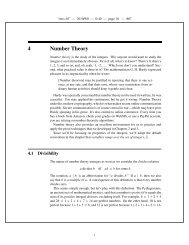
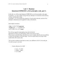
Fig. 6.0.1 In the lefthand sequence, the sphere is conducting, while on the<br />
right, it is polarizable and not conducting.<br />
or groups of molecules (domains) in which the electric field induces dipole moments.<br />
For example, suppose that the dipole moments are of an atomic scale and,<br />
in the absence of an electric field, do not exist; the moments are induced because<br />
atoms contain positively charged nuclei and electrons orbiting around the nuclei.<br />
According to quantum theory, electrons orbiting the nuclei are not to be viewed as<br />
localized at any particular instant of time. It is more appropriate to think of the<br />
electrons as “clouds” of charge surrounding the nuclei. Because the charge of the<br />
orbiting electrons is equal and opposite to the charge of the nuclei, a neutral atom<br />
has no net charge. An atom with no permanent dipole moment has the further
Sec. 6.0<br />
Introduction<br />
3<br />
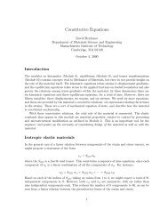
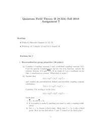
Fig. 6.0.2 Nucleus with surrounding electronic charge cloud displaced by<br />
applied electric field.<br />
property that the center of the negative charge of the electron “clouds” coincides<br />
with the center of the positive charge of the nuclei. In the presence of an electric<br />
field, the center of positive charge is pulled in the direction of the field while the<br />
center of negative charge is pushed in the opposite direction. At the atomic level,<br />
this relative displacement of charge centers is as sketched in Fig. 6.0.2. Because the<br />
two centers of charge no longer coincide, the particle acquires a dipole moment. We<br />
can represent each atom by a pair of charges of equal magnitude and opposite sign<br />
separated by a distance d.<br />
On the macroscopic scale of the sphere and in an applied field, the dipoles<br />
then appear somewhat as shown in Fig. 6.0.1d. In the interior of the sphere, the<br />
polarization leaves each positive charge in the vicinity of a negative one, and hence<br />
there is no net charge density. However, at the north pole there are no negative<br />
charges to neutralize the positive ones, and at the south pole no positive ones to<br />
pair up with the negative ones. The result is a distribution of surface charge density<br />
that does not differ qualitatively from that for the metal sphere.<br />
How can we distinguish between these two very different situations Suppose<br />
that the two spheres make contact with the lower electrode, as shown in parts (e)<br />
and (f) of the figure. By this we mean that in the case of the metal sphere, electrons<br />
are now free to pass between the sphere and the electrode. Once again, electrons<br />
move slightly downward, leaving positive sites exposed at the top of the sphere.<br />
However, some of those at the bottom flow into the lower electrode, thus reducing<br />
the amount of negative surface charge on the lower side of the metal sphere.<br />
At the top, the polarized sphere shown by Fig. 6.0.1f has a similar distribution<br />
of positive surface charge density. But one very important difference between the<br />
two situations is apparent. On an atomic scale in the ideal dielectric, the orbiting<br />
electrons are paired with the parent atom, and hence the sphere must remain neutral.<br />
Thus, the metallic sphere now has a net charge, while the one made up of<br />
dipoles does not.<br />
Experimental evidence that a metallic sphere had indeed acquired a net charge<br />
could be gained in a number of different ways. Two are clear from demonstrations<br />
in Chap. 1. A pair of spheres, each charged by “induction” in this fashion, would<br />
repel each other, and this could be demonstrated by the experiment in Fig. 1.3.10.<br />
The charge could also be measured by charge conservation, as in Demonstration<br />
1.5.1. Presumably, the same experiments carried out using insulating spheres would<br />
demonstrate the existence of no net charge.<br />
Because charge accumulations occur via displacements of paired charges (polarization)<br />
as well as of charges that can move far away from their partners of<br />
opposite sign, it is often appropriate to distinguish between these by separating the<br />
total charge density ρ into parts ρ u and ρ p , respectively, produced by unpaired and
4 <strong>Polarization</strong> Chapter 6<br />
paired charges.<br />
ρ = ρ u + ρ p (1)<br />
In this chapter, we consider insulating materials and therefore focus on the effects<br />
of the paired or polarization charge density. Additional effects of unpaired charges<br />
are taken up in the next chapter.<br />
Our first step, in Sec. 6.1, is to relate the polarization charge density to the<br />
density of dipoles– to the polarization density. We do this because it is the polarization<br />
density that can be most easily specified. Sections 6.2 and 6.3 then focus<br />
on the first of two general classes of polarization. In these sections, the polarization<br />
density is permanent and therefore specified without regard for the electric<br />
field. In Sec. 6.4, we discuss simple constitutive laws expressing the action of the<br />
field upon the polarization. This fieldinduced atomic polarization just described is<br />
typical of physical situations. The field action on the atom, molecule, or domain<br />
is accompanied by a reaction of the dipoles on the field that must be considered<br />
simultaneously. That is, within such a polarizable body placed into an electric field,<br />
a polarization charge density is produced which, in turn, modifies the electric field.<br />
In Secs. 6.5–6.7, we shall study methods by which selfconsistent solutions to such<br />
problems are obtained.<br />
6.1 POLARIZATION DENSITY<br />
The following development is applicable to polarization phenomena having diverse<br />
microscopic origins. Whether representative of atoms, molecules, groups of ordered<br />
atoms or molecules (domains), or even macroscopic particles, the dipoles are pictured<br />
as opposite charges ±q separated by a vector distance d directed from the<br />
negative to the positive charge. Thus, the individual dipoles, represented as in Sec.<br />
4.4, have moments p defined as<br />
p = qd (1)<br />
Because d is generally smaller in magnitude than the size of the atom, molecule,<br />
or other particle, it is small compared with any macroscopic dimension of interest.<br />
Now consider a medium consisting of N such polarized particles per unit<br />
volume. What is the net charge q contained within an arbitrary volume V enclosed<br />
by a surface S Clearly, if the particles of the medium within V were unpolarized,<br />
the net charge in V would be zero. However, now that they are polarized, some<br />
charge centers that were contained in V in their unpolarized state have moved out<br />
of the surface S and left behind unneutralized centers of charge. To determine the<br />
net unneutralized charge left behind in V , we will assume (without loss of generality)<br />
that the negative centers of charge are stationary and that only the positive centers<br />
of charge are mobile during the polarization process.<br />
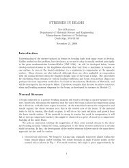
Consider the particles in the neighborhood of an element of area da on the<br />
surface S, as shown in Fig. 6.1.1. All positive centers of charge now outside S within<br />
the volume dV = d · da have left behind negative charge centers. These contribute a<br />
net negative charge to V . Because there are Nd · da such negative centers of charge<br />
in dV , the net charge left behind in V is
Sec. 6.1<br />
<strong>Polarization</strong> Density<br />
5<br />
Fig. 6.1.1 Volume element containing positive charges which have left negative<br />
charges on the other side of surface S.<br />
<br />
Q = − (qNd) · da (2)<br />
S<br />
Note that the integrand can be either positive or negative depending on whether<br />
positive centers of charge are leaving or entering V through the surface element<br />
da. Which of these possibilities occurs is reflected by the relative orientation of d<br />
and da. If d has a component parallel (antiparallel) to da, then positive centers of<br />
charge are leaving (entering) V through da.<br />
The integrand of (1) has the dimensions of dipole moment per unit volume<br />
and will therefore be defined as the polarization density.<br />
P ≡ Nqd (3)<br />
Also by definition, the net charge in V can be determined by integrating the polarization<br />
charge density over its volume.<br />
<br />
Q = ρ p dV (4)<br />
V<br />
Thus, we have two ways of calculating the net charge, the first by using the polarization<br />
density from (3) in the surface integral of (2).<br />
<br />
<br />
Q = − P · da = − · PdV<br />
(5)<br />
S<br />
Here Gauss’ theorem has been used to convert the surface integral to one over the<br />
enclosed volume. The charge found from this volume integral must be the same as<br />
given by the second way of calculating the net charge, by (4). Because the volume<br />
under consideration is arbitrary, the integrands of the volume integrals in (4) and<br />
(5) must be identical.<br />
V<br />
ρ p = − · P<br />
(6)<br />
In this way, the polarization charge density ρ p has been related to the polarization<br />
density P.
6 <strong>Polarization</strong> Chapter 6<br />
Fig. 6.1.2<br />
cylinder.<br />
<strong>Polarization</strong> surface charge due to uniform polarization of right<br />
It may seem that little has been accomplished in this development because,<br />
instead of the unknown ρ p , the new unknown P appeared. In some instances, P<br />
is known. But even in the more common cases where the polarization density and<br />
hence the polarization charge density is not known a priori but is induced by the<br />
field, it is easier to directly link P with E than ρ p with E.<br />
In Fig. 6.0.1, the polarized sphere could acquire no net charge. Our representation<br />
of the polarization charge density in terms of the polarization density<br />
guarantees that this is true. To see this, suppose V is interpreted as the volume<br />
containing the entire polarized body so that the surface S enclosing the volume V<br />
falls outside the body. Because P vanishes on S, the surface integral in (5) must<br />
vanish. Any distribution of charge density related to the polarization density by (6)<br />
cannot contribute a net charge to an isolated body.<br />
We will often find it necessary to represent the polarization density by a<br />
discontinuous function. For example, in a material surrounded by free space, such<br />
as the sphere in Fig. 6.0.1, the polarization density can fall from a finite value<br />
to zero at the interface. In such regions, there can be a surface polarization charge<br />
density. With the objective of determining this density from P, (6) can be integrated<br />
over a pillbox enclosing an incremental area of an interface. With the substitution<br />
−P → o E and ρ p → ρ, (6) takes the same form as Gauss’ law, so the proof is<br />
identical to that leading from (1.3.1) to (1.3.17). We conclude that where there is a<br />
jump in the normal component of P, there is a surface polarization charge density<br />
σ sp = −n · (P a − P b ) (7)<br />
Just as (6) tells us how to determine the polarization charge density for a given<br />
distribution of P in the volume of a material, this expression serves to evaluate the<br />
singularity in polarization charge density (the surface polarization charge density)<br />
at an interface.<br />
Note that according to (6), P originates on negative polarization charge and<br />
terminates on positive charge. This contrasts with the relationship between E and<br />
the charge density. For example, according to (6) and (7), the uniformly polarized<br />
cylinder of material shown in Fig. 6.1.2 with P pointing upward has positive σ sp<br />
on the top and negative on the bottom.
Sec. 6.2<br />
Laws and Continuity<br />
7<br />
6.2 LAWS AND CONTINUITY CONDITIONS WITH POLARIZATION<br />
With the unpaired and polarization charge densities distinguished, Gauss’ law<br />
becomes<br />
· o E = ρ u + ρ p (1)<br />
where (6.1.6) relates ρ p to P.<br />
ρ p = − · P (2)<br />
Because P is an “averaged” polarization per unit volume, it is a “smooth” vector<br />
function of position on an atomic scale. In this sense, it is a macroscopic variable.<br />
The negative of its divergence, the polarization charge density, is also a macroscopic<br />
quantity that does not reflect the “graininess” of the microscopic charge distribution.<br />
Thus, as it appears in (1), the electric field intensity is also a macroscopic<br />
variable.<br />
Integration of (1) over an incremental volume enclosing a section of the interface,<br />
as carried out in obtaining (1.3.7), results in<br />
where (6.1.7) relates σ sp to P.<br />
n · o (E a − E b ) = σ su + σ sp (3)<br />
σ sp = −n · (P a − P b ) (4)<br />
These last two equations, respectively, give expression to the continuity condition<br />
of Gauss’ law, (1), at a surface of discontinuity.<br />
<strong>Polarization</strong> Current Density and Ampère’s Law. Gauss’ law is not the<br />
only one affected by polarization. If the polarization density varies with time, then<br />
the flow of charge across the surface S described in Sec. 6.1 comprises an electrical<br />
current. Thus, we need to investigate charge conservation, and more generally the<br />
effect of a timevarying polarization density on Ampére’s law. To this end, the<br />
following steps lead to the polarization current density implied by a timevarying<br />
polarization density.<br />
According to the definition of P evolved in Sec. 6.1, the process of polarization<br />
transfers an amount of charge dQ<br />
dQ = P · da (5)<br />
through a surface area element da. This is perhaps envisioned in terms of the<br />
volume d · da shown in Fig. 6.2.1. If the polarization density P varies with time,<br />
then according to this equation, charge is passed through the area element at a<br />
finite rate. For a change in qNd, or P, of ΔP, the amount of charge that has<br />
passed through the incremental area element da is<br />
Δ(dQ) = ΔP · da (6)
8 <strong>Polarization</strong> Chapter 6<br />
Fig. 6.2.1 Charges passing through area element da result in polarization<br />
current density.<br />
Note that we have two indicators of differentials in this expression. The d<br />
refers to the fact that Q is differential because da is a differential. The rate of<br />
change with time of dQ, Δ(dQ)/Δt, can be identified with a current di p through<br />
da, from side (b) to side (a).<br />
Δ(dQ) ∂P<br />
di p = = · da (7)<br />
Δt ∂t<br />
The partial differentiation symbol is used to distinguish the differentiation with<br />
respect to t from the space dependence of P.<br />
A current di p through an area element da is usually written as a current<br />
density dotmultiplied by da<br />
di p = J p · da (8)<br />
Hence, we compare these last two equations and deduce that the polarization current<br />
density is<br />
∂P<br />
J p = (9)<br />
∂t<br />
Note that J p and ρ p , via (2) and (9), automatically obey a continuity law having<br />
the same form as the charge conservation equation, (2.3.3).<br />
· J p +<br />
∂ρ p<br />
= 0 (10)<br />
∂t<br />
Hence, we can think of a rate of charge transport in a material medium as consisting<br />
of a current density of unpaired charges J u and a polarization current density J p ,<br />
each obeying its own conservation law. This is also implied by Ampère’s law, as<br />
now generalized to include the effects of polarization.<br />
In the EQS approximation, the magnetic field intensity is not usually of interest,<br />
and so Ampère’s law is of secondary importance. But if H were to be determined,<br />
J p would make a contribution. That is, Ampère’s law as given by (2.6.2) is<br />
now written with the current density divided into paired and unpaired parts. With<br />
the latter given by (9), Ampère’s differential law, generalized to include polarization,<br />
is<br />
∂<br />
× H = J u + ( o E + P) (11)<br />
∂t
Sec. 6.3<br />
Permanent <strong>Polarization</strong><br />
9<br />
This law is valid whether quasistatic approximations are to be made or not. However,<br />
it is its implication for charge conservation that is usually of interest in the<br />
EQS approximation. Thus, the divergence of (11) gives zero on the left and, in view<br />
of (1), (2), and (9), the expression becomes<br />
∂ρ u ∂ρ p<br />
· J u + + · J p + = 0 (12)<br />
∂t<br />
∂t<br />
Thus, with the addition of the polarization current density to (11), the divergence of<br />
Ampère’s law gives the sum of the conservation equations for polarization charges,<br />
(10), and unpaired charges<br />
∂ρ u<br />
· J u + = 0 (13)<br />
∂t<br />
In the remainder of this chapter, it will be assumed that in the polarized material,<br />
ρ u is usually zero. Thus, (13) will not come into play until Chap. 7.<br />
Displacement Flux Density. Primarily in dealing with fielddependent polarization<br />
phenomena, it is customary to define a combination of quantities appearing<br />
in Gauss’ law and Ampère’s law as the displacement flux density D.<br />
D ≡ o E + P (14)<br />
We regard P as representing the material and E as a field quantity induced by<br />
the external sources and the sources within the material. This suggests that D be<br />
considered a “hybrid” quantity. Not all texts on electromagnetism take this point<br />
of view. Our separation of all quantities appearing in Maxwell’s equations into field<br />
and material quantities aids in the construction of models for the interaction of<br />
fields with matter.<br />
With ρ p replaced by (2), Gauss’ law (1) can be written in terms of D defined<br />
by (14),<br />
· D = ρ u<br />
(15)<br />
while the associated continuity condition, (3) with σ sp replaced by (4), becomes<br />
n · (D a − D b ) = σ su (16)<br />
The divergence of D and the jump in normal D determine the unpaired charge<br />
densities. Equations (15) and (16) hold, unchanged in form, both in free space and<br />
matter. To adapt the laws to free space, simply set D = o E.<br />
Ampère’s law is also conveniently written in terms of D. Substitution of (14)<br />
into (11) gives<br />
∂D<br />
× H = J u +<br />
∂t (17)
10 <strong>Polarization</strong> Chapter 6<br />
Now the displacement current density ∂D/∂t includes the polarization current density.<br />
6.3 PERMANENT POLARIZATION<br />
Usually, the polarization depends on the electric field intensity. However, in some<br />
materials a permanent polarization is “frozen” into the material. Ideally, this means<br />
that P(r, t) is prescribed, independent of E. Electrets, used to make microphones<br />
and telephone speakers, are often modeled in this way.<br />
With P a given function of space, and perhaps of time, the polarization charge<br />
density and surface charge density follow from (6.2.2) and (6.2.4) respectively. If<br />
the unpaired charge density is also given throughout the material, the total charge<br />
density in Gauss’ law and surface charge density in the continuity condition for<br />
Gauss’ law are known. [The righthand sides of (6.2.1) and (6.2.3) are known.]<br />
Thus, a description of permanent polarization problems follows the same format as<br />
used in Chaps. 4 and 5.<br />
Examples in this section are intended to develop an appreciation for the relationship<br />
between the polarization density P, the polarization charge density ρ p ,<br />
and the electric field intensity E. It should be recognized that once ρ p is determined<br />
from the given P, the methods of Chaps. 4 and 5 are directly applicable.<br />
The distinction between paired and unpaired charges is sometimes academic.<br />
By subjecting an insulating material to an extremely large field, especially at an<br />
elevated temperature, it is possible to coerce molecules or domains of molecules<br />
into a polarization state that is retained for some period of time at lower fields<br />
and temperatures. It is natural to take this as a state of permanent polarization.<br />
But, if ions are made to impact the surface of the material, they can form sites of<br />
permanent charge. Certainly, the origin of these ions suggests that they be regarded<br />
as unpaired. Yet if the material attracts other charges to become neutral, as it tends<br />
to do, these permanent charges could also be regarded as due to polarization and<br />
represented by a permanent polarization charge density.<br />
In this section, the EQS laws prevail. Thus, with the understanding that<br />
throughout the region of interest (exclusive of enclosing boundaries) the charge<br />
densities are given,<br />
E = −Φ (1)<br />
2 Φ = − 1 <br />
o<br />
(ρ u + ρ p ) (2)<br />
The example now considered is akin to that pictured qualitatively in Fig. 6.1.2.<br />
By making the uniformly polarized material spherical, it is possible to obtain a<br />
simple solution for the field distribution.<br />
Example 6.3.1.<br />
A Permanently Polarized Sphere<br />
A sphere of material having radius R is uniformly polarized along the z axis,<br />
P = P o i z (3)
Sec. 6.3 Permanent <strong>Polarization</strong> 11<br />
Given that the surrounding region is free space with no additional field sources,<br />
what is the electric field intensity E produced by this permanent polarization<br />
The first step is to establish the distribution of ρ p, in the material volume<br />
and on its surfaces. In the volume, the negative divergence of P is zero, so there<br />
is no volumetric polarization charge density (6.2.2). This is obvious with P written<br />
in Cartesian coordinates. It is less obvious when P is expressed in its spherical<br />
coordinate components.<br />
P = P o cos θi r − P o sin θi θ (4)<br />
Abrupt changes of the normal component of P entail polarization surface charge<br />
densities. These follow from using (4) to evaluate the continuity condition of (6.2.4)<br />
applied at r = R, where the normal component is i r and region (a) is outside the<br />
sphere.<br />
σ sp = P o cos θ (5)<br />
This surface charge density gives rise to E.<br />
Now that the field sources have been identified, the situation reverts to one<br />
much like that illustrated by Problem 5.9.2. Both within the sphere and in the<br />
surrounding free space, the potential must satisfy Laplace’s equation, (2), with ρ u +<br />
ρ p = 0. In terms of Φ the continuity conditions at r = R implied by (1) and (2)<br />
[(5.3.3) and (6.2.3)] with the latter evaluated using (5) are<br />
Φ o − Φ i = 0 (6)<br />
∂Φ o ∂Φ i<br />
− o + o = P o cos θ (7)<br />
∂r ∂r<br />
where (o) and (i) denote the regions outside and inside the sphere.<br />
The source of the E field represented by this potential is a surface polarization<br />
charge density that varies cosinusoidally with θ. It is possible to fulfill the boundary<br />
conditions, (6) and (7), with the two spherical coordinate solutions to Laplace’s<br />
equation (from Sec. 5.9) having the θ dependence cos θ. Because there are no sources<br />
in the region outside the sphere, the potential must go to zero as r → ∞. Of the<br />
two possible solutions having the cos θ dependence, the dipole field is used outside<br />
the sphere.<br />
cos θ<br />
Φ o = A (8)<br />
r<br />
2<br />
Inside the sphere, the potential must be finite, so this solution is excluded. The<br />
solution is<br />
Φ i = Br cos θ (9)<br />
which is that of a uniform electric field intensity. Substitution of these expressions<br />
into the continuity conditions, (6) and (7), gives expressions from which cos θ can be<br />
factored. Thus, the boundary conditions are satisfied at every point on the surface<br />
if<br />
A<br />
− BR = 0 (10)<br />
R 2<br />
A<br />
2 o + o B = P o (11)<br />
R 3<br />
These expressions can be solved for A and B, which are introduced into (8) and (9)<br />
to give the potential distribution<br />
P o R 3 cos θ<br />
Φ o = (12)<br />
3 o r 2
12 <strong>Polarization</strong> Chapter 6<br />
Fig. 6.3.1 Equipotentials and lines of electric field intensity of permanently<br />
polarized sphere having uniform polarization density. Inset shows<br />
polarization density and associated surface polarization charge density.<br />
i<br />
P o<br />
Φ = r cos θ (13)<br />
3 o<br />
Finally, the desired distribution of electric field is obtained by taking the negative<br />
gradient of this potential.<br />
P o R 3<br />
E o = 3o r 3 (2 cos θi r + sin θi θ ) (14)<br />
i<br />
P o<br />
E = (− cos θi r + sin θi θ ) (15)<br />
3 o<br />
With the distribution of polarization density shown in the inset, Fig. 6.3.1 shows<br />
this electric field intensity. It comes as no surprise that the E lines originate on the<br />
positive charge and terminate on the negative. The polarization density originates<br />
on negative polarization charge and terminates on positive polarization charge. The<br />
resulting electric field is classic because outside it is exactly that of a dipole at the<br />
origin, while inside it is uniform.<br />
What would be the moment of the dipole at the origin giving rise to the same<br />
external field as the uniformly polarized sphere This can be seen from a comparison<br />
of (12) and (4.4.10).<br />
4 3<br />
|P | = 3<br />
πR P o (16)<br />
The moment is simply the volume multiplied by the uniform polarization density.<br />
There are two new ingredients in the next example. First, the region of interest<br />
has boundaries upon which the potential is constrained. Second, the given polarization<br />
density represents a volumetric distribution of polarization charge density<br />
rather than a surface distribution.<br />
Example 6.3.2.<br />
Fields Due to Volume <strong>Polarization</strong> Charge<br />
with Boundary Conditions
Sec. 6.3 Permanent <strong>Polarization</strong> 13<br />
Fig. 6.3.2 Periodic distribution of polarization density and associated<br />
polarization charge density ( ρ o < 0) gives rise to potential and field<br />
shown in Fig. 5.6.2.<br />
Fig. 6.3.3<br />
Crosssection of electret microphone.<br />
Plane parallel electrodes, in the planes y = ±a, are constrained to zero potential. In<br />
the planar region between, the polarization density is the spatially periodic function<br />
ρ o<br />
P = −i x sin βx (17)<br />
β<br />
We wish to determine the field distribution.<br />
First, the distribution of polarization charge density is determined by taking<br />
the negative divergence of (17) [(17) is substituted into (6.1.6)].<br />
ρ p = ρ o cos βx (18)<br />
The distribution of polarization density and polarization charge density which has<br />
been found is shown in Fig. 6.3.2 (ρ o < 0).<br />
Now the situation reverts to solving Poisson’s equation, given this source distribution<br />
and subject to the zero potential conditions on the boundaries at y = ±a.<br />
The problem is identical to that considered in Example 5.6.1. The potential and field<br />
are the superposition of particular and homogeneous parts depicted in Fig. 5.6.2.<br />
The next example illustrates how a permanent polarization can conspire with<br />
a mechanical deformation to produce a useful electrical signal.<br />
Example 6.3.3.<br />
An Electret Microphone<br />
Shown in crosssection in Fig. 6.3.3 is a thin sheet of permanently polarized material<br />
having thickness d. It is bounded from below by a fixed electrode having the potential<br />
v and from above by an air gap. On the other side of this gap is a conducting<br />
grounded diaphragm which serves as the movable element of a microphone. It is<br />
mounted so that it can undergo displacements. Thus, the spacing h = h(t). Given<br />
h(t), what is the voltage developed across a load resistance R<br />
In the sheet, the polarization density is uniform, with magnitude P o , and directed<br />
from the lower electrode toward the upper one. This vector has no divergence,
14 <strong>Polarization</strong> Chapter 6<br />
Fig. 6.3.4 (a) Distribution of polarization density and surface charge<br />
density in electret microphone. (b) Electric field intensity and surface<br />
polarization and unpaired charges.<br />
and so evaluation of (6.1.6) shows that the polarization charge density is zero in the<br />
volume of the sheet. The polarization surface charge density on the electret air gap<br />
interface follows from (6.1.7) as<br />
σ sp = −n · (P a − P b ) = P o (19)<br />
Because σ sp is uniform and the equipotential boundaries are plane and parallel, the<br />
electric field in the air gap [region (a)] and in the electret [region (b)] are taken as<br />
uniform. <br />
Ea ; d < x < h<br />
E = i x (20)<br />
E b ; 0 < x < d<br />
Formally, we have just solved Laplace’s equation in each of the bulk regions. The<br />
fields E a and E b must satisfy two conditions. First, the potential difference between<br />
the electrodes is v, so<br />
<br />
h<br />
v = E x dx = dE b + (h − d)E a (21)<br />
0<br />
Second, Gauss’ jump condition at the electret air gap interface, (6.2.3), requires that<br />
o E a − o E b = P o (22)<br />
Simultaneous solution of these last two expressions evaluates the electric fields<br />
in terms of v and h.<br />
v d P o<br />
E a = + (24a)<br />
h h o<br />
E b =<br />
v<br />
−<br />
h<br />
(h − d) Po<br />
(24b)<br />
h<br />
What has been found is illustrated in Fig. 6.3.4. The uniform P and associated<br />
σ sp shown in part (a) combine with the unpaired charges on the lower electrode<br />
and upper diaphragm to produce the fields shown in part (b). In this picture, it is<br />
assumed that v is positive and (h − d)P o/ o > v. In the air gap, the field due to the<br />
unpaired charges on the electrodes reinforces that due to σ sp, while in the electret,<br />
it opposes the downwarddirected field due to σ sp.<br />
To compute the current i, defined in Fig. 6.3.3, the lower electrode and the<br />
electret are enclosed by a surface S, and Gauss’ law is used to evaluate the enclosed<br />
unpaired charge.<br />
<br />
· ( o E + P) = ρ u ⇒ q =<br />
o<br />
( o E + P) · nda (25)<br />
S
Sec. 6.3 Permanent <strong>Polarization</strong> 15<br />
Just how the surface S cuts through the system does not matter. Here we take the<br />
surface as enclosing the lower electrode by passing through the air gap. It follows<br />
from (24) that the unpaired charge is<br />
<br />
A o dP o<br />
q = A o E a = v + (26)<br />
h<br />
where A is the area of the electrode.<br />
Conservation of unpaired charge requires that the current be the rate of change<br />
of the total unpaired charge on the lower electrode.<br />
o<br />
dq<br />
i = (27)<br />
dt<br />
With the resistor attached to the terminals (the input resistance of an amplifier<br />
driven by the microphone), the voltage and current must also satisfy Ohm’s law.<br />
v = −iR (28)<br />
These last three relations combine to give an expression for v(t), given h(t).<br />
<br />
v A o dP o dh Ao dv<br />
− = − v + +<br />
R h<br />
2<br />
dt h dt<br />
o<br />
(29)<br />
This differential equation has timevarying coefficients. Not only is this equation<br />
difficult to solve, but also the predicted voltage response cannot be a good<br />
replica of h(t), as required for a good microphone, if all terms are of equal importance.<br />
That situation can be remedied if the deflections h 1 are kept small compared<br />
with the equilibrium position, h o h 1 . In the absence of a time variation of h 1 , it<br />
is clear from (29) that v is zero. By making h 1 small, we can make v small.<br />
Expanding the righthand side of (29) to first order in h 1 , dh 1 /dt, v, and<br />
dv/dt, we obtain<br />
dv v C o<br />
dPo dh1<br />
C o + = (30)<br />
dt R h o o dt<br />
where C o = A o /h o .<br />
We could solve this equation for its response to a sinusoidal drive. Alternatively,<br />
the resulting frequency response can be determined, with more physical<br />
insight, by considering two limits. First, suppose that time rate of change is so slow<br />
(frequencies so low) that the first term on the left is negligible compared to the<br />
second. Then the output voltage is<br />
v =<br />
C oR dPo dh1<br />
; ωRC o 1 (31)<br />
h o o dt<br />
In this limit, the resistor acts as a short. The charge can be determined by the<br />
diaphragm displacement with the contribution of v ignored (i.e., the charge required<br />
to produce v by charging the capacitance C o is ignored). The small but finite voltage<br />
is then obtained as the time rate of change of the charge multiplied by −R.<br />
Second, suppose that time rates of change are so rapid that the second term<br />
is negligible compared to the first. Within an integration constant,<br />
dP o h 1<br />
v = ; ωRC o 1 (32)<br />
o h o
16 <strong>Polarization</strong> Chapter 6<br />
Fig. 6.3.5 Frequency response of electret microphone for imposed diaphragm<br />
displacement.<br />
In this limit, the electrode charge is essentially constant. The voltage is obtained<br />
from (26) with q set equal to its equilibrium value, (A o/h o)(dP o/ o).<br />
The frequency response gleaned from these asymptotic responses is in Fig. 6.3.5.<br />
Because its displacement was taken as known, we have been able to ignore the<br />
dynamical equations of the diaphragm. If the mass and damping of the diaphragm<br />
are ignored, the displacement indeed reflects the pressure of a sound wave. In this<br />
limit, a linear distortionfree response of the microphone to pressure is assured at<br />
frequencies ω > 1/RC. However, in predicting the response to a sound wave, it is<br />
usually necessary to include the detailed dynamics of the diaphragm.<br />
In a practical microphone, subjecting the electret sheet to an electric field<br />
would induce some polarization over and beyond the permanent component P o .<br />
Thus, a more realistic model would incorporate features of the linear dielectrics<br />
introduced in Sec. 6.4.<br />
6.4 CONSTITUTIVE LAWS OF POLARIZATION<br />
Dipole formation, or orientation of dipolar particles, usually depends on the local<br />
field in which the particles are situated. This local microscopic field is not necessarily<br />
equal to the macroscopic E field. Yet certain relationships between the macroscopic<br />
quantities E and P can be established without a knowledge of the relations between<br />
the local microscopic fields and the macroscopic E fields. Usually, these relations,<br />
called constitutive laws, originate in experimental observations characteristic of the<br />
material being investigated.<br />
First, the permanent polarization model developed in the previous section is<br />
one constitutive law. In such a medium, P(r) is prescribed independent of E.<br />
There are media, and these are much more common, in which the polarization<br />
depends on E. Consider an isotropic medium, which, in the absence of an electric<br />
field has no preferred orientation. Amorphous media such as glass are isotropic.<br />
Crystalline media, made up of randomly oriented microscopic crystals, also behave<br />
as isotropic media on a macroscopic scale. If we assume that the polarization P in<br />
an isotropic medium depends on the instantaneous field and not on its past history,<br />
then P is a function of E<br />
P = P(E) (1)<br />
where P and E are parallel to each other. Indeed, if P were not parallel to E, then<br />
a preferred direction different from the direction of E would need to exist in the<br />
medium, which contradicts the assumption of isotropy. A possible relation between
Sec. 6.5 Fields in Linear Dielectrics 17<br />
Fig. 6.4.1<br />
<strong>Polarization</strong> characteristic for nonlinear isotropic material.<br />
the magnitudes of E and P is shown in Fig. 6.4.1 and represents an “electrically<br />
nonlinear” medium for which P “saturates” for large values of E.<br />
If the medium is electrically linear, in addition to being isotropic, then a linear<br />
relationship exists between E and P<br />
P = o χ e E (2)<br />
where χ e is the dielectric susceptibility. Typical values are given in Table 6.4.1.<br />
All isotropic media behave as linear media and obey (2) if the applied E field is<br />
sufficiently small. As long as E is small enough, any continuous function P(E) can<br />
be expanded in a Taylor series of E and broken off with the first term in E. (An<br />
isotropic medium cannot have a term in the Taylor expansion independent of E.)<br />
For a linear isotropic material, where (2) is obeyed, it follows that D and E<br />
are related by<br />
where<br />
D = E (3)<br />
≡ o (1 + χ e ) (4)<br />
is the permittivity or dielectric constant. The permittivity normalized to o , (1+χ e ),<br />
is the relative dielectric constant.<br />
In our discussion, it has been assumed that the state of polarization depends<br />
only on the instantaneous electric field intensity. There are materials in which the<br />
polarization depends not only on the current electric field intensity but on the<br />
sequence of preceding states as well (hysteresis). Because we will find magnetization<br />
phenomena analogous in many ways to polarization phenomena, we will defer<br />
consideration of hysteretic phenomena to Chap. 9.<br />
Many types of transducers exploit the dependence of polarization on variables<br />
other than the electric field. In pyroelectric materials, polarization is a function of<br />
temperature. Pyroelectrics are used for optical detectors of highpower infrared radiation.<br />
Piezoelectric materials have a polarization which is a function of strain<br />
(deformation). Such media are suited to lowpower electromechanical energy conversion.
18 <strong>Polarization</strong> Chapter 6<br />
TABLE 6.4.1<br />
MATERIAL DIELECTRIC SUSCEPTIBILITIES<br />
Air,<br />
Gases<br />
0 ◦ C. . . . . . . . . . . . . . . . . . . . . . . . . . . . . . . . . . . . . 0.00059<br />
40 atmospheres . . . . . . . . . . . . . . . . . . . . . . . . . 0.0218<br />
80 atmospheres . . . . . . . . . . . . . . . . . . . . . . . . . 0.0439<br />
Carbon dioxide, 0 ◦ C . . . . . . . . . . . . . . . . . . . . . . . . . 0.000985<br />
Hydrogen, 0 ◦ C . . . . . . . . . . . . . . . . . . . . . . . . . . . . . . 0.000264<br />
Water vapor, 145 ◦ C . . . . . . . . . . . . . . . . . . . . . . . . . 0.00705<br />
Liquids<br />
χ e<br />
Acetone, 0 ◦ C . . . . . . . . . . . . . . . . . . . . . . . . . . . . . . . . 25.6<br />
Air, 191 ◦ C. . . . . . . . . . . . . . . . . . . . . . . . . . . . . . . . . . 0.43<br />
Alcohol<br />
amyl . . . . . . . . . . . . . . . . . . . . . . . . . . . . . . . . . . . . 16.0<br />
ethyl . . . . . . . . . . . . . . . . . . . . . . . . . . . . . . . . . . . . 24.8<br />
methyl . . . . . . . . . . . . . . . . . . . . . . . . . . . . . . . . . . 30.2<br />
Benzene . . . . . . . . . . . . . . . . . . . . . . . . . . . . . . . . . . . . . 1.29<br />
Glycerine, 15 ◦ C . . . . . . . . . . . . . . . . . . . . . . . . . . . . . 55.2<br />
Oils,<br />
castor . . . . . . . . . . . . . . . . . . . . . . . . . . . . . . . . . . . 3.67<br />
linseed . . . . . . . . . . . . . . . . . . . . . . . . . . . . . . . . . . 2.35<br />
corn . . . . . . . . . . . . . . . . . . . . . . . . . . . . . . . . . . . . 2.1<br />
Water, distilled . . . . . . . . . . . . . . . . . . . . . . . . . . . . . . 79.1<br />
Solids<br />
χ e<br />
Diamond . . . . . . . . . . . . . . . . . . . . . . . . . . . . . . . . . . . . 15.5<br />
Glass,<br />
flint, density 4.5 . . . . . . . . . . . . . . . . . . . . . . . . 8.90<br />
flint, density 2.87 . . . . . . . . . . . . . . . . . . . . . . . 5.61<br />
lead, density 3.03.5 . . . . . . . . . . . . . . . . . . . . . 4.47.0<br />
Mica . . . . . . . . . . . . . . . . . . . . . . . . . . . . . . . . . . . . . . . . 4.65.0<br />
Paper (cable insulation) . . . . . . . . . . . . . . . . . . . . . 1.01.5<br />
Paraffin . . . . . . . . . . . . . . . . . . . . . . . . . . . . . . . . . . . . . 1.1<br />
Porcelain . . . . . . . . . . . . . . . . . . . . . . . . . . . . . . . . . . . . 4.7<br />
Quartz,<br />
1 to axis . . . . . . . . . . . . . . . . . . . . . . . . . . . . . . . . 3.69<br />
11 to axis . . . . . . . . . . . . . . . . . . . . . . . . . . . . . . . 4.06<br />
Rubber . . . . . . . . . . . . . . . . . . . . . . . . . . . . . . . . . . . . . . 1.33.0<br />
Shellac . . . . . . . . . . . . . . . . . . . . . . . . . . . . . . . . . . . . . . 2.1<br />
χ e
Sec. 6.5 Fields in Linear Dielectrics 19<br />
Fig. 6.5.1 Field region filled by (a) uniform dielectric, (b) piecewise uniform<br />
dielectric and (c) smoothly varying dielectric.<br />
6.5 FIELDS IN THE PRESENCE OF ELECTRICALLY<br />
LINEAR DIELECTRICS<br />
In Secs. 6.2 and 6.3, the polarization density was given independently of the electric<br />
field intensity. In this and the next two sections, the polarization is induced by the<br />
electric field. Not only does the electric field give rise to the polarization, but in<br />
return, the polarization modifies the field. The polarization feeds back on the electric<br />
field intensity.<br />
This “feedback” is described by the constitutive law for a linear dielectric.<br />
Thus, (6.4.3) and Gauss’ law, (6.2.15), combine to give<br />
· E = ρ u (1)<br />
and the electroquasistatic form of Faraday’s law requires that<br />
× E = 0 ⇒ E = −Φ (2)<br />
The continuity conditions implied by these two laws across an interface separating<br />
media having different permittivities are (6.2.16) expressed in terms of the constitutive<br />
law and either (5.3.1) or (5.3.4). These are<br />
n · ( a E a − b E b ) = σ su (3)<br />
n × (E a − E b ) = 0 ⇒ Φ a − Φ b = 0 (4)<br />
Figure 6.5.1 illustrates three classes of situations involving linear dielectrics.<br />
In the first, the entire region of interest is filled with a uniform dielectric. In the<br />
second, the region of interest can be broken into uniform subregions within which
20 <strong>Polarization</strong> Chapter 6<br />
the permittivity is constant. The continuity conditions are needed to insure that<br />
the basic laws are satisfied through the interfaces between these regions. Systems<br />
of this type are said to be composed of piecewise uniform dielectrics. Finally, the<br />
dielectric material may vary in its permittivity over dimensions that are on the same<br />
order as those of interest. Such a smoothly inhomogeneous dielectric is illustrated<br />
in Fig. 6.5.1c.<br />
The remainder of this section makes some observations that are generally<br />
applicable provided that ρ u = 0 throughout the volume of the region of interest.<br />
Section 6.6 is devoted to systems having uniform and piecewise uniform dielectrics,<br />
while Sec. 6.7 illustrates fields in smoothly inhomogeneous dielectrics.<br />
Capacitance. How does the presence of a dielectric alter the capacitance To<br />
answer this question, recognize that conservation of unpaired charge, as expressed<br />
by (6.2.13), still requires that the current i measured at terminals connected to a<br />
pair of electrodes is the time rate of change of the unpaired charge on the electrode.<br />
In view of Gauss’ law, with the effects of polarization included, (6.2.15), the net<br />
unpaired charge on an electrode enclosed by a surface S is<br />
<br />
q = ρ u dV = · DdV = D · nda (5)<br />
V<br />
V<br />
Here, Gauss’ theorem has been used to convert the volume integral to a surface<br />
integral.<br />
We conclude that the capacitance of an electrode (a) relative to a reference<br />
electrode (b) is<br />
<br />
<br />
D · nda D · nda<br />
S S<br />
C = =<br />
(6)<br />
b<br />
E ds v<br />
a C ·<br />
Note that this is the same as for electrodes in free space except that o E → D.<br />
Because there is no unpaired charge density in the region between the electrodes,<br />
S is any surface that encloses the electrode (a). As before, with no polarization, E<br />
is irrotational, and therefore C is any contour connecting the electrode (a) to the<br />
reference (b).<br />
In an electrically linear dielectric, where D = E, both the numerator and<br />
denominator of (6) are proportional to the voltage, and as a result, the capacitance<br />
C is independent of the voltage. However, with the introduction of an electrically<br />
nonlinear material, perhaps having the polarization constitutive law of Fig. 6.4.1,<br />
the numerator of (6) is not a linear function of the voltage. As defined by (6), the<br />
capacitance is then a function of the applied voltage.<br />
S<br />
Induced <strong>Polarization</strong> Charge. Stated as (1)–(4), the laws and continuity<br />
conditions for fields in a linear dielectric put the polarization charge out of view.<br />
Yet it is this charge that contains the effect of the dielectric on the field. Where<br />
does the polarization charge accumulate<br />
Again, assuming that ρ u is zero, a vector identity casts Gauss’ law as given<br />
by (1) into the form<br />
· E + E · = 0 (7)
Sec. 6.6 PieceWise Uniform Electrically Linear Dielectrics 21<br />
Multiplied by o and divided by , this expression can be written as<br />
· o E =<br />
− o<br />
E · (8)<br />
<br />
Comparison of this expression to Gauss’ law written in terms of ρ p , (6.2.1), shows<br />
that the polarization charge density is<br />
ρ p = − o<br />
E · (9)<br />
<br />
This equation makes it clear that polarization charge will be induced only<br />
where there are gradients in . A special case is where there is an abrupt discontinuity<br />
in . Then the gradient in (9) is singular and represents a polarization surface<br />
charge density (the gradient represents the spatial derivative of a step function,<br />
which is an impulse). This surface charge density can best be determined by making<br />
use of the polarization charge density continuity condition, (6.1.7). Substitution<br />
of the constitutive law P = ( − o )E then gives<br />
σ sp = −n · [( a − o )E a − ( b − o )E b ] (10)<br />
Because σ su = 0, it follows from the jump condition for n · D, (3), that<br />
σ sp = n o E a 1 − a<br />
<br />
·<br />
b<br />
(11)<br />
Remember that n is directed from region (b) to region (a).<br />
Because D is solenoidal, we can construct tubes of D containing constant flux.<br />
Lines of D must therefore begin and terminate on the boundaries. The constitutive<br />
law, D = E, requires that D is proportional to E. Thus, although E can intensify<br />
or rarify as it passes through a flux tube, it can not reverse direction. Therefore, if<br />
we follow a bundle of electric field lines from the boundary point of high potential<br />
to the one of low potential, the polarization charge encountered [in accordance<br />
with (9) and (11)] is positive at points where is decreasing, negative where it is<br />
increasing.<br />
Consider the examples in Fig. 6.5.1. In the case of the uniform dielectric,<br />
Fig. 6.5.1a, the typical flux tube shown passes through no variations in , and it<br />
follows from (8) that there is no volume polarization charge density. Thus, it will<br />
come as no surprise that the field distribution in this case is predicted by Laplace’s<br />
equation.<br />
In the piecewise uniform dielectrics, there is no polarization charge density<br />
in a flux tube except where it passes through an interface. For the flux tube shown,<br />
(11) shows that if the upper region has the greater permittivity ( a > b ), then<br />
there is an accumulation of negative surface charge density at the interface. Thus,<br />
the field originating on positive charges at the lower electrode is in part terminated<br />
by negative polarization surface charge at the interface, and the field in the upper<br />
region tends to be weakened relative to that below.<br />
In the smoothly inhomogeneous dielectric of Fig. 6.5.1c, the typical flux tube<br />
shown passes through a region where increases with ξ. It follows from (8) that<br />
negative polarization charge density is induced in the volume of the material. Here
22 <strong>Polarization</strong> Chapter 6<br />
again, the electric field associated with positive charge on the lower electrode is in<br />
part terminated on the polarization charge density induced in the volume. As a<br />
result, the dielectric tends to make the electric field weaken with increasing ξ.<br />
The next two sections give the opportunity to solve for the fields in simple<br />
configurations and then see that the results are consistent with the physical picture<br />
that has been found here.<br />
6.6 PIECEWISE UNIFORM ELECTRICALLY LINEAR DIELECTRICS<br />
In a region where the permittivity is uniform and where there is no unpaired<br />
charge, the electric potential obeys Laplace’s equation.<br />
This follows from (6.5.1) and (6.5.2).<br />
2 Φ = 0 (1)<br />
Uniform Dielectrics. If all of the region of interest is filled by a uniform<br />
dielectric, it is clear from the foregoing that all equations developed for fields in free<br />
space are now valid in the presence of the uniform dielectric. The only alteration is<br />
the replacement of the permittivity of free space o by that of the uniform dielectric.<br />
In every problem from Chaps. 4 and 5 where Φ and E were determined in a region<br />
of free space bounded by equipotentials, that region could just as well be filled with<br />
a uniform dielectric, and for the same potentials the electric field intensity would be<br />
unaltered. However, the surface charge density σ su on the boundaries would then<br />
be increased by the ratio / o .<br />
Illustration.<br />
Capacitance of a Sphere<br />
A sphere having radius R has a potential v relative to infinity. Formally, the potential,<br />
and hence the electric field, follow from (1).<br />
Evaluation of the capacitance, (6.5.6), then gives<br />
R R<br />
Φ = v ⇒ E = v (2)<br />
r r 2<br />
q 4πR 2<br />
C ≡ = E r | r=R = 4πR (3)<br />
v v<br />
The dielectric has increased the capacitance in the ratio of the dielectric constant<br />
of the material to the dielectric constant of free space.<br />
The susceptibilities listed in Table 6.4.1 illustrate the increase in capacitance<br />
that would be observed if vacuum were replaced by one of the materials. In gases,<br />
atoms or molecules are so dilute that the increase in capacitance is usually negligible.<br />
With solids and liquids, the increase is of practical importance. Some, having
Sec. 6.6 PieceWise Uniform Dielectrics 23<br />
Fig. 6.6.1 (a) Plane parallel capacitor with region between electrodes<br />
occupied by a dielectric. (b) Artificial dielectric composed of cubic array<br />
of perfectly conducting spheres having radius R and spacing s.<br />
molecules of large permanent dipole moments that are aligned by the field, increase<br />
the capacitance dramatically.<br />
The following example is intended to provide an appreciation for why the<br />
polarized dielectric increases the capacitance.<br />
Example 6.6.1.<br />
An Artificial Dielectric<br />
In the plane parallel capacitor of Fig. 6.6.1, the electric field intensity is (v/d)i z.<br />
Thus, the unpaired charge density on the lower electrode is D z = v/d, and if the<br />
electrode area is A, the capacitance is<br />
q A A<br />
C ≡ = D z | z=0 = (4)<br />
v v d<br />
Here we assume that d is much less than either of the electrode dimensions, so the<br />
fringing fields can be ignored.<br />
Now consider the plane parallel capacitor of Fig. 6.6.1b. The dielectric is composed<br />
of “molecules” that are actually perfectly conducting spheres. These have<br />
radius R and are in a cubic array with spacing s >> R. With the application of<br />
a voltage, the spheres acquire the positive and negative surface charges on their<br />
northern and southern poles required to make their surfaces equipotentials. In so<br />
far as the field outside the spheres is concerned, the system is modeled as an array<br />
of dipoles, each induced by the applied field.<br />
If there are many of the spheres, the change in capacitance caused by inserting<br />
the array between the plates can be determined by treating it as a continuum. This<br />
we will do under the assumption that s >> R. In that case, the field in regions<br />
removed several radii from the sphere centers is essentially uniform, and taken as<br />
E z = v/d. The resulting field in the vicinity of a sphere is then as determined in<br />
Example 5.9.1. The dipole moment of each sphere follows from a comparison of the<br />
potential for the perfectly conducting sphere in a uniform electric field, (5.9.7), with<br />
that of a dipole, (4.4.10).<br />
p = 4π o R 3 E a (5)<br />
The polarization density is the moment/dipole multiplied by the number of<br />
dipoles per unit volume, the number density N.<br />
P z = o(4πR 3 N)E a (6)<br />
For the cubic array, a unit volume contains 1/s 3 spheres, and so<br />
1<br />
N = (7)<br />
s 3
24 <strong>Polarization</strong> Chapter 6<br />
Fig. 6.6.2 From the microscopic point of view, the increase in capacitance<br />
results because the dipoles adjacent to the electrode induce image<br />
charges on the electrode in addition to those from the unpaired charges<br />
on the opposite electrode.<br />
From (6) and (7) it follows that<br />
P = o<br />
4π<br />
R 3 E (8)<br />
s<br />
Thus, the polarization density is a linear function of E. The susceptibility follows<br />
from a comparison of (8) with (6.4.2) and, in turn, the permittivity is given by<br />
(6.4.4).<br />
χ e = 4π R 3 R 3 <br />
⇒ = 1 + 4π o (9)<br />
s<br />
s<br />
Of course, this expression is accurate only if the interaction between spheres is<br />
negligible.<br />
As the array of spheres is inserted between the electrodes, surface charges are<br />
induced, as shown in Fig. 6.6.2. Within the array, each cap of positive surface charge<br />
on the north pole of a sphere is compensated by an opposite charge on the south<br />
pole of a neighboring sphere. Thus, on a scale large compared to the spacing s, there<br />
is no charge density in the volume of the array. Nevertheless, the average field at<br />
the electrode is larger than the applied field E a . This is caused by surface charges<br />
on the last layers of spheres which have their images in unpaired charges on the<br />
electrodes. For a given applied voltage, the field between the top and bottom layers<br />
of spheres and the adjacent electrodes is increased, with an attendant increase in<br />
observed capacitance.<br />
Demonstration 6.6.1.<br />
Artificial Dielectric<br />
In Fig. 6.6.3, the artificial dielectric is composed of an array of pingpong balls with<br />
conducting coatings. The parallel plate capacitor is in one leg of a bridge, as shown in<br />
the circuit pictured in Fig. 6.6.4. The resistors shunt the input terminals of balanced<br />
amplifiers so that the oscilloscope displays v o . With the array removed, capacitor<br />
C 2 is adjusted to null the output voltage v o . The output voltage resulting from the<br />
the insertion of the array is a measure of the change in capacitance. To simplify the<br />
interpretation of this voltage, the resistances R s are made small compared to the<br />
impedance of the parallel plate capacitor. Thus, almost all of the applied voltage V<br />
appears across the lower legs of the bridge. With the introduction of the array, the<br />
change in current through the parallel plate capacitor is
Sec. 6.6 PieceWise Uniform Dielectrics 25<br />
Fig. 6.6.3 Demonstration in which change in capacitance is used to measure<br />
the equivalent dielectric constant of an artificial dielectric.<br />
Fig. 6.6.4 Balanced amplifiers of oscilloscope, balancing capacitors,<br />
and demonstration capacitor shown in Fig. 6.6.4 comprise the elements<br />
in the bridge circuit. The driving voltage comes from the transformer,<br />
while v o is the oscilloscope voltage.<br />
|Δi| = ω(ΔC)|V | (10)<br />
Thus, there is a change of current through the resistance in the right leg and hence<br />
a change of voltage across that resistance given by<br />
v o = R s ω(ΔC)V (11)<br />
Because the current through the left leg has remained the same, this change in<br />
voltage is the measured output voltage.<br />
2<br />
Typical experimental values are R = 1.87 cm, s = 8 cm, A = (0.40) 2 m ,<br />
d = 0.15 m, ω = 2π (250 Hz), R s = 100 kΩ and V = 566 v peak with a measured<br />
voltage of v o = 0.15 V peak. From (4), (9), and (11), the output voltage is predicted<br />
to be 0.135 V peak.<br />
PieceWise Uniform Dielectrics. So far we have only considered systems<br />
filled with uniform dielectrics, as in Fig. 6.5.1a. We turn now to the description of<br />
fields in piecewise uniform dielectrics, as exemplified by Fig. 6.5.1b.
26 <strong>Polarization</strong> Chapter 6<br />
Fig. 6.6.5 Insulating rod having uniform permittivity b surrounded<br />
by material of uniform permittivity a . Uniform electric field is imposed<br />
by electrodes that are at “infinity.”<br />
In each of the regions of constant permittivity, the field distribution is described<br />
by Laplace’s equation, (1). The field problem is attacked by solving this<br />
equation in each of the regions and then using the jump conditions to match these<br />
solutions at the surfaces of discontinuity between the dielectrics. The following example<br />
has a relatively simple solution that helps form further insights.<br />
Example 6.6.2.<br />
Dielectric Rod in Uniform Transverse Field<br />
A uniform electric field E o i x , perhaps produced by means of a parallel plate capacitor,<br />
exists in a dielectric having permittivity a . With its axis perpendicular to<br />
this field, a circular cylindrical dielectric rod having permittivity b and radius R is<br />
introduced, as shown in Fig. 6.6.5. With the understanding that the electrodes are<br />
sufficiently far from the rod so that the field at “infinity” is essentially uniform, our<br />
objective is to determine and then interpret the electric field inside and outside the<br />
rod.<br />
The shape of the circular cylindrical boundary suggests that we use polar<br />
coordinates. In these coordinates, x = r cos φ, and so the potential far from the<br />
cylinder is<br />
Φ(r → ∞) → −E o r cos φ (12)<br />
Because this potential varies like the cosine of the angle, it is reasonable to attempt<br />
satisfying the jump conditions with solutions of Laplace’s equation having the same<br />
φ dependence. Thus, outside the cylinder, the potential is assumed to take the form<br />
R<br />
Φ a = −E or cos φ + A cos φ (13)<br />
r<br />
Here the dipole field is multiplied by an adjustable coefficient A, but the uniform<br />
field has a magnitude set to match the potential at large r, (12).<br />
Inside the cylinder, the solution with a 1/r dependence cannot be accepted<br />
because it becomes singular at the origin. Thus, the only solution having the cosine<br />
dependence on φ is a uniform field, with the potential<br />
r<br />
Φ b = B cos φ (14)<br />
R<br />
Can the coefficients A and B be adjusted to satisfy the two jump conditions implied<br />
by the laws of Gauss and Faraday, (6.5.3) and (6.5.4), at r = R<br />
a b<br />
a E r − b E r = 0 (15)
Sec. 6.6 PieceWise Uniform Dielectrics 27<br />
Fig. 6.6.6 Electric field intensity in and around dielectric rod of Fig.<br />
6.6.5 for (a) b > a and (b) b ≤ a .<br />
Φ a − Φ b = 0 (16)<br />
Substitution of (13) and (14) into these conditions shows that the answer is yes.<br />
Continuity of potential, (16), requires that<br />
while continuity of normal D, (15), is satisfied if<br />
(−E o R + A) cos φ = B cos φ (17)<br />
A b B<br />
− a E o − a cos φ = cos φ (18)<br />
R R<br />
Note that these conditions contain the cos φ dependence on both sides, and so can<br />
be satisfied at each angle φ. This confirms the correctness of the originally assumed<br />
φ dependence of our solutions. Simultaneous solution of (17) and (18) for A and B<br />
gives<br />
b − a<br />
A = E oR (19)<br />
b + a<br />
B =<br />
−2 a<br />
E o R (20)<br />
b + a<br />
Introducing these values of the coefficients into the potentials, (13) and (14), gives<br />
Φ a = −RE o cos φ<br />
r −<br />
R (b − a) (21)<br />
R r ( b + a )<br />
Φ b =<br />
−2 a<br />
E or cos φ (22)<br />
b + a<br />
The electric field is obtained as the gradient of this potential.<br />
<br />
E a = E o i r cos φ 1 + R 2 ( b − a ) <br />
− i φ sin φ 1 − R 2 ( b − a ) (23)<br />
r ( b + a) r b + a<br />
E b = 2a E o(i r cos φ − i φ sin φ) (24)<br />
b + a
28 <strong>Polarization</strong> Chapter 6<br />
Fig. 6.6.7 Surface polarization charge density responsible for distortion of<br />
fields as shown in Fig. 6.6.6. (a) b > a, (b) a > b .<br />
The electric field intensity given by these expressions is shown in Fig. 6.6.6. If<br />
the cylinder has the higher dielectric constant, as would be the case for a dielectric<br />
rod in air, the lines of electric field intensity tend to concentrate in the rod. In the<br />
opposite case– for example, representing a cylindrical void in a dielectric– the field<br />
lines tend to skirt the cylinder.<br />
With an understanding of the relationship between the electric field intensity<br />
and the induced polarization charge comes the ability to see in advance how dielectrics<br />
distort the electric field. The circular cylindrical dielectric rod introduced<br />
into a uniform tranverse electric field in Example 6.6.2 serves as an illustration.<br />
Without carrying out the detailed analysis which led to (23) and (24), could we see<br />
in advance that the electric field has the distribution illustrated in Fig. 6.6.6<br />
The induced polarization charge provides the sources for the field induced by<br />
polarized material. For piecewise uniform dielectrics, this is a polarization surface<br />
charge, given by (6.5.11).<br />
σ sp = n o E a 1 − a<br />
<br />
·<br />
b<br />
(25)<br />
The electric field intensity in the cylindrical rod example is generally directed to<br />
the right. It follows from (25) that the distribution of surface polarization charge<br />
at the cylindrical interface is as illustrated in Fig. 6.6.7. With the rod having the<br />
higher permittivity, Fig. 6.6.7a, the induced positive polarization surface charge<br />
density is at the right and the negative surface charge is at the left. These charges<br />
give rise to fields that generally originate at the positive charge and terminate at<br />
the negative. Thus, it is clear without any analysis that if b > a , the induced field<br />
inside tends to cancel the imposed field. In this case, the interior field is decreased<br />
or “depolarized.” In the exterior region, vector addition of the induced field to<br />
the rightdirected imposed field shows that incoming field lines at the left must be<br />
deflected inward, while outgoing ones at the right are deflected outward.<br />
These same ideas, applied to the case where a > b , show that the interior<br />
field is increased while the exterior one tends to be ducted around the cylinder.<br />
The circular cylinder is one of a series of examples having exact solutions.<br />
These give the opportunity to highlight the physical phenomena without encumbering<br />
mathematics. If it is actually necessary to account for detailed geometry,
Sec. 6.6 PieceWise Uniform Dielectrics 29<br />
Fig. 6.6.8 Grounded upper electrode and lower electrode extending<br />
from x = 0 to x → ∞ form plane parallel capacitor with fringing field<br />
that extends into the region 0 < x between grounded electrodes.<br />
then some of the approaches introduced in Chaps. 4 and 5 can be used. The following<br />
example illustrates the use of the orthogonal modes approach introduced in<br />
Sec. 5.5.<br />
Example 6.6.3.<br />
Fringing Field of Dielectric Filled Parallel<br />
Plate Capacitor<br />
Fields are to be determined in the planar region between a grounded conductor in<br />
the plane y = a and a pair of conductors in the plane y = 0, shown in Fig. 6.6.8. To<br />
the right of x = 0 in the y = 0 plane is a second grounded conductor. To the left of<br />
x = 0 in this same plane is an electrode at the potential V . The regions to the right<br />
and left of the plane x = 0 are, respectively, filled with uniform dielectrics having<br />
permittivities a and b . Under the assumption that the system extends to infinity<br />
in the ±x and ±z directions, we now determine the fringing fields in the vicinity of<br />
the interface between dielectrics.<br />
Our approach is to write solutions to Laplace’s equation in the respective<br />
regions that satisfy the boundary conditions in the planes y = 0 and y = a and<br />
as x → ± . These are then matched up by the jump conditions at the interface<br />
between dielectrics.<br />
Consider first the region to the right, where Φ = 0 in the planes y = 0 and<br />
y = a and goes to zero as x → ∞. From Table 5.4.1, we select the infinite set of<br />
solutions<br />
<br />
∞<br />
nπ x nπ<br />
Φ a = A n e − a sin y (26)<br />
a<br />
n=1<br />
Here we have set k = nπ/a so that the sine functions are zero at each of the<br />
boundaries.<br />
In the region to the left, the field is uniform in the limit x → −∞. This suggests<br />
writing the solution as the sum of a “particular” part meeting the “inhomogeneous<br />
part” of the boundary condition and a homogeneous part that is zero on each of the<br />
boundaries.<br />
<br />
∞<br />
nπ x nπ<br />
Φ b = −V y<br />
− 1 + B n e a sin y (27)<br />
a<br />
a<br />
n=1<br />
The coefficients A n and B n must now be adjusted so that the jump conditions<br />
are met at the interface between the dielectrics, where x = 0. First, consider the<br />
jump condition on the potential, (6.5.4). Evaluated at x = 0, (26) and (27) must<br />
give the same potential regardless of y.<br />
Φ a <br />
<br />
<br />
b<br />
= Φ<br />
x=0 x=0<br />
⇒<br />
<br />
∞<br />
A n sin y = −V y<br />
nπ<br />
a<br />
− 1 +<br />
a<br />
<br />
∞<br />
n=1 n=1<br />
nπ<br />
B n sin y (28)<br />
a
30 <strong>Polarization</strong> Chapter 6<br />
To satisfy this relation at each value of y, expand the linear potential distribution<br />
on the right in a series of the same form as the other two terms.<br />
∞<br />
− 1 nπ<br />
−V y <br />
= V n sin y (29)<br />
a<br />
a<br />
n=1<br />
Multiplication of both sides by sin(mπy/a) and integration from y = 0 to y = a<br />
gives only one term on the right and an integral that can be carried out on the left.<br />
Hence, we can solve for the coefficients V n in (29).<br />
<br />
0<br />
a<br />
−V y<br />
a<br />
− 1 mπ aV m<br />
sin ydy = ⇒ V n = 2V (30)<br />
a 2<br />
nπ<br />
Thus, the series provided by (29) and (30) can be substituted into (28) to obtain an<br />
expression with each term a sum over the same type of series.<br />
∞<br />
∞<br />
∞<br />
nπ 2V nπ nπ<br />
A n sin y = sin y + B n sin y (31)<br />
a nπ a a<br />
n=1 n=1 n=1<br />
This expression is satisfied if the coefficients of the like terms are equal. Thus, we<br />
have<br />
2V<br />
A n = + B n (32)<br />
nπ<br />
To make the normal component of D continuous at the interface,<br />
∂Φ a ∂Φ b ∞<br />
nπ nπ<br />
− a = − b ⇒ a A n sin y<br />
∂x x=0 ∂x x=0 a a<br />
n=1<br />
<br />
∞<br />
nπ nπ<br />
= − b<br />
a Bn sin a y<br />
n=1<br />
(33)<br />
and a second relation between the coefficients results.<br />
a A n = − b B n (34)<br />
The coefficients A n and B n are now determined by simultaneously solving (32) and<br />
(34). These are substituted into the original expressions for the potential, (26) and<br />
(27), to give the desired potential distribution.<br />
Φ a =<br />
<br />
∞<br />
b<br />
Φ = −V y<br />
− 1 −<br />
a<br />
2V nπ x nπ<br />
nπ e − a sin<br />
<br />
1 + a a y (35)<br />
n=1 b<br />
<br />
∞<br />
2 a V nπ x nπ<br />
e a sin<br />
nπ b 1 +<br />
a a y (36)<br />
n=1 b<br />
These potential distributions, and sketches of the associated fields, are illustrated<br />
in Fig. 6.6.9. Shown first is the uniform dielectric. Laplace’s equation prevails<br />
throughout, even at the “interface.” Far to the left, we know that the potential is
Sec. 6.7 Inhomogeneous Dielectrics 31<br />
Fig. 6.6.9 Equipotentials and field lines for configuration of Fig. 6.6.8.<br />
(a) Fringing for uniform dielectric. (b) With high permittivity material<br />
between capacitor plates, field inside tends to become tangential to the<br />
interface and uniform throughout the region to the left. (c) With high<br />
permittivity material outside the region between the capacitor plates,<br />
the field inside tends to be perpendicular to the interface.<br />
linear in y, and hence represented by the equally spaced parallel straight lines. These<br />
lines must end at other points on the bounding surface having the same potential.<br />
The only place where this is possible is in the singular region at the origin where<br />
the potential makes an abrupt change from V to 0. These observations provide a<br />
starting point in sketching the field lines.<br />
Shown next is the field distribution in the limit where the permittivity between<br />
the capacitor plates (to the left) is very large compared to that outside. As is clear<br />
by taking the limit a / b → 0 in (36), the field inside the capacitor tends to be<br />
uniform right up to the edge of the capacitor. The dielectric effectively ducts the<br />
electric field. As far as the field inside the capacitor is concerned, there tends to be<br />
no normal component of E.<br />
In the opposite extreme, where the region to the right has a high permittivity<br />
compared to that between the capacitor plates, the electric field inside the capacitor<br />
tends to approach the interface normally. As far as the potential to the left is<br />
concerned, the interface is an equipotential.<br />
In Chap. 9, we find that magnetization and polarization phenomena are analogous.<br />
There we delve further into approximations on magnetic field distributions in<br />
the presence of magnetizable materials that can just as well be used to understand<br />
systems of piecewise uniform dielectrics.
32 <strong>Polarization</strong> Chapter 6<br />
6.7 SMOOTHLY INHOMOGENEOUS ELECTRICALLY LINEAR<br />
DIELECTRICS<br />
The potential distribution in a dielectric that is free of unpaired charge and which<br />
has a spacevarying permittivity is governed by<br />
· Φ = 0 (1)<br />
This is (6.5.1) combined with (6.5.2) and with ρ u = 0. The contribution of the<br />
spatially varying permittivity is emphasized by using the vector identity for the<br />
divergence of a scalar () times a vector (Φ).<br />
2 Φ + Φ · <br />
= 0 (2)<br />
<br />
With a spatially varying permittivity, polarization charge is induced in proportion<br />
to the component of E that is in the direction of the gradient in . Thus, in general,<br />
the potential is not a solution to Laplace’s equation.<br />
Equation (2) gives a different perspective to the approach taken in dealing with<br />
piecewise uniform systems. In Sec. 6.6, the polarization charge density represented<br />
by the term in (2) is confined to interfaces and accounted for by jump conditions.<br />
Thus, the section was a variation on the theme of Laplace’s equation. The theme<br />
of this section broadens the developments of Sec. 6.6.<br />
It is the objective in this section to demonstrate how familiar methods are<br />
adapted to dealing with unfamiliar laws. In general, (2) has spatially varying coefficients.<br />
Thus, even though it is linear, we are not guaranteed simple closedform<br />
solutions. However, if the spatial dependence of is exponential, the equation does<br />
have constant coefficients and simple solutions. Our example exploits this fact.<br />
Example 6.7.1.<br />
Fields in an Exponentially Varying Dielectric<br />
A dielectric has a permittivity that varies exponentially in the y direction, as<br />
illustrated in Fig. 6.7.1a.<br />
= (y) = p e −βy (3)<br />
Here p and β are given constants.<br />
In this example, the dielectric fills the rectangular region shown in Fig. 6.7.1b.<br />
This configuration is familiar from Sec. 5.5. The fields are two dimensional, Φ = 0<br />
at x = 0 and x = a and y = 0. The potential on the “last” surface, where y = b, is<br />
v(t).<br />
It follows from (3) that<br />
Φ · <br />
= −β ∂ Φ<br />
∂y<br />
(4)<br />
and (2) becomes<br />
∂ 2 Φ ∂ 2 Φ ∂Φ<br />
∂x 2 +<br />
∂y 2 − β ∂y<br />
= 0 (5)
Sec. 6.7 Inhomogeneous Dielectrics 33<br />
Fig. 6.7.1 (a) Smooth permittivity distribution of material enclosed<br />
by (b) zero potential boundaries at x = 0, x = a, and y = 0, and<br />
electrode at potential v at y = b.<br />
The dielectric fills a region having boundaries that are natural in Cartesian<br />
coordinates. Thus, we look for product solutions having the form Φ = X(x)Y (y).<br />
Substitution into (5) gives<br />
<br />
1 d 2 Y 1 dY 1 d 2 X<br />
− + = 0 (6)<br />
Y dy 2 β dy X dx 2<br />
The first term, a function of y alone, must sum with the function of x alone to give<br />
zero. Thus, the first is set equal to the separation coefficient k 2 and the second equal<br />
to −k 2 .<br />
d 2 X 2<br />
+ k X = 0 (7)<br />
dx 2<br />
d 2 Y<br />
dy 2<br />
dY<br />
− β − k 2 Y = 0 (8)<br />
dy<br />
This assignment of sign for the separation coefficient is motivated by the requirement<br />
that Φ = 0 at two locations. This results in periodic solutions for (7).<br />
sin kx<br />
X = (9)<br />
cos kx<br />
Because it also has constant coefficients, the solutions to (8) are exponentials. Substitution<br />
of exp(py) shows that<br />
<br />
β β 2<br />
p = ± + k 2 2<br />
2 (10)<br />
and it follows that solutions are linear combinations of two exponentials.<br />
⎡ <br />
β cosh<br />
β<br />
⎤<br />
2<br />
+ k<br />
2 2 y<br />
Y = e 2 y ⎣ ⎦<br />
(11)<br />
β<br />
2<br />
sinh + k 2 y<br />
2
34 <strong>Polarization</strong> Chapter 6<br />
For the specific problem at hand, we look for the products of these sets of<br />
solutions that satisfy the homogeneous boundary conditions. Those at x = 0 and<br />
x = a are met by making k = nπ/a, with n an integer. The origin of the y axis<br />
was made to coincide with the third zero potential boundary so that the hyperbolic<br />
sine function could be used. Thus, we arrive at an infinite series of solutions, each<br />
satisfying the homogeneous boundary conditions.<br />
Φ =<br />
∞<br />
<br />
n=1<br />
<br />
β<br />
y <br />
A n e 2<br />
β 2 nπ 2 nπ <br />
sinh + y sin x<br />
2 a a<br />
(12)<br />
The assignment of the coefficients so that the potential constraint at y = b is<br />
met follows the procedure familiar from Sec. 5.5.<br />
β<br />
2 <br />
+ nπ<br />
<br />
∞<br />
2<br />
4v β sinh y<br />
Φ = e 2 (y−b) 2 a nπ <br />
sin x<br />
nπ<br />
β<br />
2 <br />
+ nπ<br />
2 a<br />
n=1 sinh b<br />
odd 2 a<br />
(13)<br />
For interpretation of (13), suppose that β is positive so that decreases with<br />
y, as illustrated in Fig. 6.7.1a. Without the analysis, we know that the lines of<br />
D originate on the electrode at y = b and terminate on the zero potential walls.<br />
This means that E lines either terminate on the grounded walls or on polarization<br />
charges induced in the volume. If v > 0, we can see from (6.5.9) that because E · <br />
is positive, the induced polarization charge density must be negative. Thus, some of<br />
the E lines terminate on this negative charge density and it comes as no surprise that<br />
we have found a potential that decays away from the excitation electrode at y = b<br />
at a rate that is faster than if the potential were governed by Laplace’s equation.<br />
The electric field is effectively shielded out of the lower region of higher permittivity<br />
by the induced polarization charge.<br />
One approach to determining fields in spatially varying dielectrics is suggested<br />
in Fig. 6.7.2. The smooth distribution has been approximated by “stair steps.”<br />
Physically, the equivalent system consists of uniform layers. Thus, the fields revert<br />
to the solutions of Laplace’s equation matched to each other at the interfaces<br />
by the jump conditions. According to (6.5.11), E lines originating at y = b and<br />
passing downward through these interfaces will induce positive surface polarization<br />
charge. Thus, replacing the smoothly varying dielectric with the layers of uniform<br />
dielectric is equivalent to representing the volume polarization charge density by a<br />
distribution of surface polarization charges.<br />
6.8 SUMMARY<br />
Table 6.8.1 is useful both as an outline of this chapter and as a reference. Gauss’<br />
theorem is the basis for deriving the surface relations in the righthand column<br />
from the respective volume relations in the lefthand column. By remembering the<br />
volume relations, one is able to recall the surface relations.<br />
Our first task, in Sec. 6.1, was to introduce the polarization density as a<br />
way of representing the polarization charge density. The first volume and surface
Sec. 6.8 Summary 35<br />
Stairstep distribution of permittivity approximating smooth dis<br />
Fig. 6.7.2<br />
tribution.<br />
relations resulted. These are deceptively similar in appearance to Gauss’ law and<br />
the associated jump condition. However, they are not electric field laws. Rather,<br />
they simply relate the volume and surface sources representing the material to the<br />
polarization density.<br />
Next we considered the fields due to permanently polarized materials. The<br />
polarization density was given. For this purpose, Gauss’ law and the associated<br />
jump condition were conveniently written as (6.2.2) and (6.2.3), respectively.<br />
With the polarization induced by the field itself, it was convenient to introduce<br />
the displacement flux density D and write Gauss’ law and the jump condition<br />
as (6.2.15) and (6.2.16). In particular, for linear polarization, the equivalent constitutive<br />
laws of (6.4.2) and (6.4.3) were introduced.<br />
The theme of this chapter has been the determination of EQS fields when the<br />
polarization charge density makes a contribution. In cases where the polarization<br />
density is given, this is easy to keep in mind, because the first step in formulating a<br />
problem is to evaluate ρ p from the given P. However, when ρ p is induced, variables<br />
such as D are used and we must be reminded that when all is said and done, ρ p<br />
(or its surface counterpart, σ sp ) is still responsible for the effect of the material on<br />
the field. The expressions for ρ p and σ sp given by the last two relations in the table<br />
are useful not only for interpreting the distributions of fields after they have been<br />
found but for forming an impression of the fields in complex systems where it would<br />
not be worthwhile to find an analytic solution. Remember that these relations hold<br />
only in regions where there is no unpaired charge density.<br />
In Chap. 9, we will find that most of this chapter is directly applicable to the<br />
description of magnetization. There we will continue to develop insights that will<br />
be equally applicable to the polarization phenomena of this chapter.
36 <strong>Polarization</strong> Chapter 6<br />
TABLE 6.8.1<br />
SUMMARY OF POLARIZATION RELATIONS AND LAWS<br />
<strong>Polarization</strong> Charge Density and <strong>Polarization</strong> Density<br />
ρ p = − · P (6.1.6) σ sp = −n · (P a − P b ) 6.1.7)<br />
Gauss’ Law with <strong>Polarization</strong><br />
· o E = ρ p + ρ u<br />
· D = ρ u<br />
where<br />
D ≡ o E + P<br />
(6.2.1)<br />
(6.2.15)<br />
(6.2.14)<br />
n · o (E a − E b ) = σ sp + σ su<br />
n · (D a − D b ) = σ su<br />
(6.2.3)<br />
(6.2.16)<br />
Electrically Linear <strong>Polarization</strong><br />
Constitutive Law<br />
P = o χ e E = ( − o )E<br />
D = E<br />
(6.4.2)<br />
(6.4.3)<br />
Source Distribution, ρ u = 0<br />
ρ p = − o<br />
E · (6.5.9) σ<br />
sp = n · o E a <br />
1 − a<br />
b<br />
(6.5.11)<br />
P R O B L E M S<br />
6.1 <strong>Polarization</strong> Density<br />
6.1.1 The layer of polarized material shown in crosssection in Fig. P6.1.1, having<br />
thickness d and surfaces in the planes y = d and y = 0, has the polarization<br />
density P = P o cos βx(i x + i y ).<br />
(a) Determine the polarization charge density throughout the slab.<br />
(b) What is the surface polarization charge density on the layer surfaces
Sec. 6.3 Problems 37<br />
Fig. P6.1.1<br />
6.2 Laws and Continuity Conditions with <strong>Polarization</strong><br />
6.2.1 For the polarization density given in Prob. 6.1.1, with P o (t) = P o cos ωt:<br />
(a) Determine the polarization current density and polarization charge<br />
density.<br />
(b) Using J p and ρ p , show that the differential charge conservation law,<br />
(10), is indeed satisfied.<br />
6.3 Permanent <strong>Polarization</strong><br />
6.3.1 ∗ A layer of permanently polarized material is sandwiched between plane<br />
parallel perfectly conducting electrodes in the planes x = 0 and x = a,<br />
respectively, having potentials Φ = 0 and Φ = −V . The system extends to<br />
infinity in the ±y and ±z directions.<br />
(a) Given that P = P o cos βxi x , show that the potential between the<br />
electrodes is<br />
P o x V x<br />
Φ = (sin βx − sin βa) − (a)<br />
β o a a<br />
(b) Given that P = P o cos βyi y , show that the potential between the<br />
electrodes is<br />
<br />
P o<br />
coshβ(x − a/2) V x<br />
Φ = sin βy 1 −<br />
−<br />
(b)<br />
β o cosh(βa/2) a<br />
6.3.2 The crosssection of a configuration that extends to infinity in the ±z directions<br />
is shown in Fig. P6.3.2. What is the potential distribution inside<br />
the cylinder of rectangular crosssection<br />
6.3.3 ∗ A polarization density is given in the semiinfinite halfspace y < 0 to be<br />
P = P o cos[(2π/Λ)x]i y . There are no other field sources in the system and<br />
P o and Λ are given constants.<br />
(a) Show that ρ p = 0 and σ sp = P o cos(2πx/Λ).
38 <strong>Polarization</strong> Chapter 6<br />
Fig. P6.3.2<br />
(b) Show that<br />
Fig. P6.3.5<br />
Φ =<br />
P o Λ cos(2πx/Λ) exp(2πy/Λ); y <br />
6.3.4 A layer in the region −a < y < 0 has the polarization density P =<br />
P o i y sin β(x − x o ). In the planes y = ±a, the potential is constrained to be<br />
Φ = V cos βx, where P o , β and V are given constants. The region 0 < y < a<br />
is free space and the system extends to infinity in the ±x and ±z directions.<br />
Find the potential in regions (a) and (b) in the free space and polarized<br />
regions, respectively. (If you have already solved Prob. 5.6.12, you can solve<br />
this problem by inspection.)<br />
6.3.5 ∗ Figure P6.3.5 shows a material having the uniform polarization density<br />
P = P o i z , with a spherical cavity having radius R. On the surface of the<br />
cavity is a uniform distribution of unpaired charge having density σ su = σ o .<br />
The interior of the cavity is free space, and P o and σ o are given constants.<br />
The potential far from the cavity is zero. Show that the electric potential<br />
is<br />
− P o σ<br />
r cos θ + o R ;<br />
Φ = 3o r ≤ R<br />
o P R 3 R (a)<br />
2 o cos θ + σ<br />
− o<br />
3o r<br />
;<br />
2 o r<br />
r ≥ R<br />
6.3.6 The crosssection of a groove (shaped like a halfcylinder having radius<br />
R) cut from a uniformly polarized material is shown in Fig. P6.3.6. The
Sec. 6.3<br />
Problems<br />
39<br />
Fig. P6.3.6<br />
Fig. P6.3.7<br />
Fig. P6.3.8<br />
material rests on a grounded perfectly conducting electrode at y = 0, and<br />
P o is a given constant. Assume that the configuration extends to infinity<br />
in the y direction and find Φ in regions (a) and (b), respectively, outside<br />
and inside the groove.<br />
6.3.7 The system shown in crosssection in Fig. P6.3.7 extends to infinity in the<br />
±x and ±z directions. The electrodes at y = 0 and y = a + b are shorted.<br />
Given P o and the dimensions, what is E in regions (a) and (b)<br />
6.3.8 ∗ In the twodimensional configuration shown in Fig. P6.3.8, a perfectly conducting<br />
circular cylindrical electrode at r = a is grounded. It is coaxial<br />
with a rotor of radius b which supports the polarization density P =<br />
[P o r cos(φ − α)].<br />
(a) Show that the polarization charge density is zero inside the rotor.<br />
(b) Show that the potential functions Φ I and Φ II respectively in the<br />
regions outside and inside the rotor are<br />
Φ I 2<br />
Pob<br />
1 r <br />
= −<br />
2<br />
r a<br />
2 cos(φ − α) (a)<br />
o
40 <strong>Polarization</strong> Chapter 6<br />
Fig. P6.3.9<br />
2<br />
Φ II P o ( a − b 2 )<br />
=<br />
r cos(φ − α)<br />
2<br />
2<br />
oa<br />
(b)<br />
(c) Show that if α = Ωt, where Ω is an angular velocity, the field rotates<br />
in the φ direction with this angular velocity.<br />
6.3.9 A circular cylindrical material having radius b has the polarization density<br />
P = [P o (r m+1 /b m ) cos mφ], where m is a given positive integer. The<br />
region b < r < a, shown in Fig. P6.3.9, is free space.<br />
(a) Determine the volume and surface polarization charge densities for<br />
the circular cylinder.<br />
(b) Find the potential in regions (a) and (b).<br />
(c) Now the cylinder rotates with the constant angular velocity Ω. Argue<br />
that the resulting potential is obtained by replacing φ → (φ − Ωt).<br />
(d) A section of the outer cylinder is electrically isolated and connected to<br />
ground through a resistance R. This resistance is low enough so that,<br />
as far as the potential in the gap is concerned, the potential of the<br />
segment can still be taken as zero. However, as the rotor rotates, the<br />
charge induced on the segment is time varying. As a result, there is a<br />
current through the resistor and hence an output signal v o . Assume<br />
that the segment subtends an angle π/m and has length l in the z<br />
direction, and find v o .<br />
6.3.10 ∗ Plane parallel electrodes having zero potential extend to infinity in the x−z<br />
planes at y = 0 and y = d.<br />
(a) In a first configuration, the region between the electrodes is free space,<br />
except for a segmented electrode in the plane x = 0 which constrains<br />
the potential there to be V (y). Given V (y), what is the potential<br />
distribution in the regions 0 < x and x < 0, regions (a) and (b),<br />
respectively<br />
(b) Now the segmented electrode is removed and the region x < 0 is filled<br />
with a permanently polarized material having P = P o i x , where P o is a<br />
given constant. What continuity conditions must the potential satisfy<br />
in the x = 0 plane
Sec. 6.5<br />
Problems<br />
(c) Show that the potential is given by<br />
41<br />
∞<br />
dP o<br />
[1 − (−1) n ] nπ nπ <br />
Φ =<br />
sin y exp x ; x >
42 <strong>Polarization</strong> Chapter 6<br />
Fig. P6.5.1<br />
Fig. P6.5.3<br />
6.5.3 ∗ The region of Fig. P6.5.3 between plane parallel perfectly conducting electrodes<br />
in the planes y = 0 and y = l is filled by a uniformly inhomogeneous<br />
dielectric having permittivity = o [1+χ a (1+y/l)]. The electrode at y = 0<br />
has potential v relative to that at y = l. The electrode separation l is much<br />
smaller than the dimensions of the system in the x and z directions, so the<br />
fields can be regarded as not depending on x or z.<br />
(a) Show that D y is independent of y.<br />
(b) With the electrodes having area A, show that the capacitance is<br />
C =<br />
o A<br />
1 + 2χa<br />
<br />
χa /ln<br />
l 1 + χ a<br />
(a)<br />
6.5.4 The dielectric in the system of Prob. 6.5.3 is replaced by one having permittivity<br />
= p exp(−y/d), where p is constant. What is the capacitance<br />
C<br />
6.5.5 In the two configurations shown in crosssection in Fig. P6.5.5, circular<br />
cylindrical conductors are used to make coaxial capacitors. In Fig. P6.5.5a,<br />
the linear dielectric has a wedge shape with interfaces with the free space<br />
region that are surfaces of constant φ. In Fig. P6.5.5b, the interface is at<br />
r = R.<br />
(a) Determine E(r) in regions (1) and (2) in each configuration, showing<br />
that simple fields satisfy all boundary conditions on the electrode<br />
surfaces and at the interfaces between dielectric and free space.<br />
(b) For lengths l in the z direction, what are the capacitances<br />
6.5.6 ∗ For the configuration of Fig. P6.5.5a, the wedgeshaped dielectric is replaced<br />
by one that fills the gap (over all φ as well as over the radius
Sec. 6.6<br />
Problems<br />
43<br />
Fig. P6.5.5<br />
Fig. P6.6.1<br />
b < r < a) with material having the permittivity = a + b cos 2 φ, where<br />
a and b are constants. Show that the capacitance is<br />
C = (2 a + b )πl/ln(a/b)<br />
(a)<br />
6.6 PieceWise Uniform Electrically Linear Dielectrics<br />
6.6.1 ∗ An insulating sphere having radius R and uniform permittivity s is surrounded<br />
by free space, as shown in Fig. P6.6.1. It is immersed in an electric<br />
field E o (t)i z that, in the absence of the sphere, is uniform.<br />
(a) Show that the potential is<br />
Φ = E o (t)<br />
−r cos θ + R 3A cos θ<br />
r ; R r<br />
2 <<br />
Br cos θ;<br />
r < R<br />
(a)<br />
where A = ( s − o )/( s + 2 o ) and B = −3 o /( s + 2 o ).<br />
(b) Show that, in the limit where s → ∞, the electric field intensity<br />
tangential to the surface of the sphere goes to zero. Thus, the surface<br />
becomes an equipotential.<br />
(c) Show that the same solution is obtained for the potential outside the<br />
sphere as in the limit s → ∞ if this boundary condition is used at<br />
the outset.
44 <strong>Polarization</strong> Chapter 6<br />
Fig. P6.6.2<br />
6.6.2 An electric dipole having a zdirected moment p is situated at the origin,<br />
as shown in Fig. P6.6.2. Surrounding it is a spherical cavity of free space<br />
having radius a. Outside of the radius a is a linearly polarizable dielectric<br />
having permittivity .<br />
(a) Determine Φ and E in regions (a) and (b) outside and inside the<br />
cavity.<br />
(b) Show that in the limit where → ∞, the electric field intensity tangential<br />
to the interface of the dielectric goes to zero. That is, in this<br />
limit, the effect of the dielectric on the interior fields is the same as<br />
if the dielectric were a perfect conductor.<br />
(c) Show that the same interior potential is obtained as in the limit →<br />
∞ if this boundary condition is used at the outset.<br />
6.6.3 ∗ In Example 6.6.1, an artificial dielectric is made from an array of perfectly<br />
conducting spheres. Here, an artificial dielectric is constructed using an<br />
array of rods, each having a circular crosssection with radius R. The rods<br />
run parallel to the capacitor plates and hence perpendicular to the imposed<br />
electric field intensity. The spacing between rod centers is s, and they are<br />
in a square array. Show that, for s large enough so that the fields induced<br />
by the rods do not interact, the equivalent electric susceptibility is χ c =<br />
2π(R/s) 2 .<br />
6.6.4 Each of the conducting spheres in the artificial dielectric of Example 6.6.1<br />
is replaced by the dielectric sphere of Prob. 6.6.1. Again, with the understanding<br />
that the spacing between spheres is large enough to justify<br />
ignoring their interaction, what is the equivalent susceptibility of the array<br />
6.6.5 ∗ A point charge finds itself at a height h above an infinite halfspace of<br />
dielectric material. The charge has magnitude q, the dielectric has a uniform<br />
permittivity , and there are no unpaired charges in the volume of the<br />
dielectric or on its surface. The Cartesian coordinates x and z are in the<br />
plane of the dielectric interface, while y is directed perpendicular to the<br />
interface and into the free space region. Thus, the charge is at y = h.<br />
The field in the free space region can be taken as the superposition of a<br />
particular solution due to the point charge and a homogeneous solution<br />
due to a charge q b at y = −h below the interface. The field in the dielectric<br />
can be taken as that of a charge q a at y = h.
Sec. 6.6<br />
Problems 45<br />
(a) Show that the potential is given by<br />
<br />
1 (q/r+ ) − (q b /r −);<br />
Φ = 4πo q a /r + ;<br />
0 < y<br />
y < 0<br />
<br />
where r = x<br />
2<br />
± + (y h) 2 + z 2 and the magnitudes of the charges<br />
turn out to be<br />
2q<br />
q <br />
<br />
− 1 <br />
o<br />
q a = <br />
; q b = <br />
+ 1<br />
<br />
(b)<br />
+ 1<br />
o<br />
(b) Show that the charge is attracted to the dielectric with the force<br />
o<br />
q b<br />
f = q<br />
16π o h 2<br />
(c)<br />
6.6.6<br />
6.6.7 ∗<br />
The halfspace y > 0 is filled by a dielectric having uniform permittivity a ,<br />
while the remaining region 0 > y is filled by a dielectric having the uniform<br />
permittivity b . Running parallel to the interface between these dielectrics<br />
along the line where x = 0 and y = h is a uniform line charge of density λ.<br />
Determine the potentials in regions (a) and (b), respectively.<br />
If the permittivities are nearly the same, so that (1 − a / b ) ≡ κ is small,<br />
the qualitative approach to determining the field distribution given in connection<br />
with Fig. 6.6.7 can be made quantitative. That is, if κ is small, the<br />
polarization charge induced by the imposed field can be determined to a<br />
good approximation and that charge, in turn, used to find the change in<br />
the applied field. Consider the following approximate approach to finding<br />
the fields in and around the dielectric cylinder of Example 6.6.2.<br />
(a) In the limit where κ is zero, the field is equal to the applied field, both<br />
inside and outside the cylinder. Write this field in polar coordinates.<br />
(b) Show that this field gives rise to σ sp = b E o κ cos φ at the surface of<br />
the cylinder.<br />
(c) Find the field due to this induced polarization surface charge and add<br />
it to the imposed field to show that, with the firstorder contribution<br />
of the induced polarization surface charge, the field is<br />
r κR<br />
<br />
cos φ; r > R<br />
Φ = −RE o<br />
<br />
−<br />
2r (a)<br />
RR<br />
1 cos φ; r < R<br />
r<br />
− κ<br />
2<br />
(d) Expand the exact fields given by (21) and (22) to first order in κ and<br />
show that they are in agreement with this result.<br />
6.6.8<br />
As an illustration of how identification of the induced polarization charge<br />
can be used in a qualitative determination of the fields, consider the fields
46 <strong>Polarization</strong> Chapter 6<br />
Fig. P6.6.8<br />
Fig. P6.6.9<br />
between the plane parallel electrodes of Fig. P6.6.8. In Fig. P6.6.8a, there<br />
are two layers of dielectric.<br />
(a) In the limit where κ = (1 − a / b ) is zero, what is the imposed E<br />
(b) What is the σ sp induced by this field at the interface between the<br />
dielectrics.<br />
(c) For a > b , sketch the field lines in the two regions. (You should be<br />
able to see, from the superposition of the fields induced by this σ sp<br />
and that imposed, which of the fields is the greater.)<br />
(d) Now consider the more complicated geometry of Fig. 6.6.8b and carry<br />
out the same steps. Based on your deductions, draw a sketch of σ sp<br />
and E for the case where b > a .<br />
6.6.9 The configuration of perfectly conducting electrodes and perfectly insulating<br />
dielectrics shown in Fig. P6.6.9 is similar to that shown in Fig. 6.6.8<br />
except that at the left and right, the electrodes are “shorted” together<br />
and the top electrode is also divided at the middle. Thus, the ⊃ shaped<br />
electrode is grounded while the ⊂ shaped one is at potential V .<br />
(a) Determine Φ in regions (a) and (b).<br />
(b) With the permittivities equal, sketch Φ and E. (Use physical reasoning<br />
rather than the mathematical result.)<br />
(c) Assuming that the permittivities are nearly equal, use the result of<br />
(b) to deduce σ sp on the interface between dielectrics in the case<br />
where a / b is somewhat greater than and then somewhat less than<br />
1. Sketch E deduced as the sum of the fields induced by these surface<br />
charges and the imposed field.<br />
(d) With a much greater that b , draw a sketch of Φ and E in region (b).<br />
(e) With a much less than b , sketch Φ and E in both regions.<br />
6.7 Smoothly Inhomogeneous Electrically Linear Dielectrics
Sec. 6.7 Problems 47<br />
Fig. P6.7.1<br />
6.7.1 ∗ For the twodimensional system shown in Fig. P6.7.1, show that the potential<br />
in the smoothly inhomogeneous dielectric is<br />
∞<br />
V x<br />
βy/2<br />
Φ = + 2V <br />
e<br />
a nπ<br />
<br />
exp − <br />
<br />
(β/2) 2 + (nπ/a) 2 nπ <br />
y sin x<br />
a<br />
n=1<br />
(a)<br />
6.7.2 In Example 6.6.3, the dielectrics to right and left, respectively, have the permittivities<br />
a = p exp(−βx) and b = p exp(βx). Determine the potential<br />
throughout the dielectric regions.<br />
6.7.3 A linear dielectric has the permittivity<br />
2 2<br />
= a {1 + χ p exp[−(x + y + z 2 )/a 2 ]} (a)<br />
An electric field that is uniform far from the origin (where it is equal<br />
to E o i y ) is imposed.<br />
(a) Assume that / o is not much different from unity and find ρ p .<br />
(b) With this induced polarization charge as a guide, sketch E.