Electromagnetic flow meters - OPTIFLUX 4000 - Forbes Marshall
Electromagnetic flow meters - OPTIFLUX 4000 - Forbes Marshall
Electromagnetic flow meters - OPTIFLUX 4000 - Forbes Marshall

You also want an ePaper? Increase the reach of your titles
YUMPU automatically turns print PDFs into web optimized ePapers that Google loves.
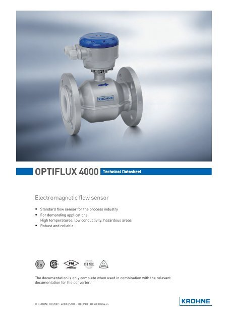
<strong>OPTIFLUX</strong> <strong>4000</strong> Technical Datasheet<br />
<strong>Electromagnetic</strong> <strong>flow</strong> sensor<br />
• Standard <strong>flow</strong> sensor for the process industry<br />
• For demanding applications:<br />
High temperatures, low conductivity, hazardous areas<br />
• Robust and reliable<br />
The documentation is only complete when used in combination with the relevant<br />
documentation for the converter.<br />
© KROHNE 03/2009 - <strong>4000</strong>525101 - TD <strong>OPTIFLUX</strong> <strong>4000</strong> R04 en
CONTENTS<br />
<strong>OPTIFLUX</strong> <strong>4000</strong><br />
1 Product features 3<br />
1.1 Standard solution for the process industry ..................................................................... 3<br />
1.2 Options.............................................................................................................................. 5<br />
1.3 Measuring principle.......................................................................................................... 7<br />
2 Technical data 8<br />
2.1 Technical data................................................................................................................... 8<br />
2.2 Vacuum load ................................................................................................................... 14<br />
2.3 Dimensions and weights ................................................................................................ 15<br />
3 Installation 19<br />
3.1 Intended use ................................................................................................................... 19<br />
3.2 Installation conditions ....................................................................................................19<br />
3.2.1 Inlet and outlet ...................................................................................................................... 19<br />
3.2.2 Mounting position.................................................................................................................. 19<br />
3.2.3 Flange deviation.................................................................................................................... 20<br />
3.2.4 T-section ............................................................................................................................... 20<br />
3.2.5 Vibration ................................................................................................................................ 20<br />
3.2.6 Magnetic field........................................................................................................................ 21<br />
3.2.7 Bends .................................................................................................................................... 21<br />
3.2.8 Open discharge ..................................................................................................................... 22<br />
3.2.9 Control valve ......................................................................................................................... 22<br />
3.2.10 Air venting ........................................................................................................................... 22<br />
3.2.11 Pump ................................................................................................................................... 23<br />
4 Electrical connections 24<br />
4.1 Safety instructions.......................................................................................................... 24<br />
4.2 Grounding ....................................................................................................................... 24<br />
4.3 Virtual reference for IFC 300 (C, W and F version) ........................................................ 25<br />
5 Notes 26<br />
2 www.krohne.com 03/2009 - <strong>4000</strong>525101 - TD <strong>OPTIFLUX</strong> <strong>4000</strong> R04 en
<strong>OPTIFLUX</strong> <strong>4000</strong><br />
PRODUCT FEATURES 1<br />
1.1 Standard solution for the process industry<br />
The <strong>OPTIFLUX</strong> <strong>4000</strong> electromagnetic <strong>flow</strong> sensor is the standard in the process industry and<br />
suitable even for demanding applications.<br />
1 All hazardous area approvals<br />
2 Housing and flanges available in stainless steel<br />
3 Most dimensionally stable PFA liner with stainless steel mesh<br />
03/2009 - <strong>4000</strong>525101 - TD <strong>OPTIFLUX</strong> <strong>4000</strong> R04 en<br />
www.krohne.com<br />
3
1 PRODUCT FEATURES<br />
<strong>OPTIFLUX</strong> <strong>4000</strong><br />
Highlights<br />
• Standard device in the process industry<br />
• Robust and reliable<br />
• More than 300,000 units operating in the field<br />
• Works reliably under demanding conditions: High temperatures (up to 180°C / 356°F) and low<br />
conductivity (non-water from 1 µS/cm, water from 20 µS/cm)<br />
• Quick and easy to install and operate<br />
• Chemically resistant to alkaline solutions and acids<br />
Industries<br />
• Chemicals<br />
• Pulp & Paper<br />
• Water<br />
• Wastewater<br />
• Minerals & Mining<br />
• Iron, Steel & Metals<br />
• Pharmaceuticals<br />
Applications<br />
• For clean liquids<br />
• For slurries and pastes with high solids content<br />
• For abrasive and aggressive products<br />
4<br />
www.krohne.com<br />
03/2009 - <strong>4000</strong>525101 - TD <strong>OPTIFLUX</strong> <strong>4000</strong> R04 en
<strong>OPTIFLUX</strong> <strong>4000</strong><br />
PRODUCT FEATURES 1<br />
1.2 Options<br />
The solution for any industry<br />
The <strong>OPTIFLUX</strong> <strong>4000</strong> has been designed for<br />
measuring any application in any industry.<br />
Throughout the history of our company, the<br />
development and application engineers have been<br />
continuously pushing the limits of feasibility in<br />
developing and testing new devices. The results are<br />
innovations that go far beyond the requirements of<br />
the customer, thereby setting new standards for the<br />
market.<br />
The <strong>OPTIFLUX</strong> <strong>4000</strong> is designed as "mother of all<br />
electromagnetic <strong>flow</strong><strong>meters</strong>", suitable for all<br />
standard and special applications, including<br />
"commercial" use according to European Directive<br />
MI-001 and -005. The level of precision complies<br />
with the industry demands, furthermore does the<br />
modular concept allow tailor-made solutions.<br />
All <strong>meters</strong> are passing specific trials,<br />
measurements and tests that go beyond the legal<br />
specifications - and on which our customers can rely<br />
100%. For example, we subject the converter<br />
electronics to a series of extensive temperature<br />
change tests, in which the converter is exposed to<br />
cyclical fluctuations ( -20...+65°C / -4...+149°F)<br />
Every meter that leaves our factory is first wetcalibrated<br />
on our officially certified calibration rigs<br />
(EN 17025).<br />
Communication<br />
<strong>Electromagnetic</strong> <strong>flow</strong><strong>meters</strong> can be installed in<br />
random locations, demanding the instrument to be<br />
suitable for any kind of environment. These locations<br />
vary from indoor use (integrated in complex<br />
processes) to outdoor use (straight forward<br />
transport, but possibly buried or submerged). The<br />
ability to read the measured results on-site may be<br />
standard, but it does not always meet the current<br />
and actual needs of the user or operator. That is why<br />
this meter comes with optional, state-of-the-art bus<br />
communication systems. The stored data is<br />
transmitted (e.g., once a day) by HART ® , Profibus,<br />
Fieldbus or Modbus, and then forwarded to a<br />
management system.<br />
03/2009 - <strong>4000</strong>525101 - TD <strong>OPTIFLUX</strong> <strong>4000</strong> R04 en<br />
www.krohne.com<br />
5
1 PRODUCT FEATURES<br />
<strong>OPTIFLUX</strong> <strong>4000</strong><br />
Construction<br />
The measuring tube of the sensor has a smooth,<br />
cylindrical shape. This design, consisting of a<br />
circular cross section (no internal or moving parts)<br />
and a homogeneous magnetic field, forms the basis<br />
for a <strong>flow</strong>-optimized pipe cross section, thereby<br />
providing reliable measurements that are largely<br />
independent of the <strong>flow</strong> profile. This design allows<br />
the sensor to measure the <strong>flow</strong> bi-directional.<br />
As an additional benefit, there is no possibility for<br />
product to build up and the free cross section sized<br />
to the customer pipeline creates no pressure drop.<br />
In addition, the required straight inlet and outlet<br />
runs are only 5D and 2D. The liner of the measuring<br />
tube is made of high tech plastic or hard rubber and<br />
is resistant to vacuum, corrosion, aging and<br />
abrasion. The surface and shape of the measuring<br />
tube also minimize mineral deposits, resulting in<br />
exemplary measurement quality - even over the long<br />
term<br />
Design and performance<br />
<strong>Electromagnetic</strong> <strong>flow</strong><strong>meters</strong> have many important<br />
advantages over their mechanical counterparts:<br />
outstanding long-term stability, maximum process<br />
reliability, no maintenance - to name just a few. As a<br />
result, these <strong>meters</strong> can deliver precise and reliable<br />
measurements for many years.<br />
The <strong>flow</strong>meter has extensive factory-set diagnostic<br />
functions that provide continuous self diagnosis in<br />
accordance with e.g. NAMUR, OIML, ISO/EN and<br />
MID. Converter operation is also monitored<br />
continuously, as are the sensor electrodes, the <strong>flow</strong><br />
profile and electronic functions. Malfunctions and<br />
irregularities are detected and immediately<br />
displayed on the high-contrast, high-resolution<br />
display.<br />
6<br />
www.krohne.com<br />
03/2009 - <strong>4000</strong>525101 - TD <strong>OPTIFLUX</strong> <strong>4000</strong> R04 en
<strong>OPTIFLUX</strong> <strong>4000</strong><br />
PRODUCT FEATURES 1<br />
1.3 Measuring principle<br />
An electrically conductive fluid <strong>flow</strong>s inside an electrically insulating pipe through a magnetic<br />
field. This magnetic field is generated by a current, <strong>flow</strong>ing through a pair of field coils. Inside of<br />
the fluid, a voltage U is generated:<br />
U = v * k * B * D<br />
in which:<br />
v = mean <strong>flow</strong> velocity<br />
k = factor correcting for geometry<br />
B = magnetic field strength<br />
D = inner diameter of <strong>flow</strong> meter<br />
The signal voltage U is picked off by electrodes and is proportional to the main <strong>flow</strong> velocity v and<br />
thus the <strong>flow</strong> rate q. The signal voltage is quite small (typically 1 mV at v = 3 m/s / 10 ft/s and field<br />
coil power of 1 W). Finally, a signal converter is used to amplify the signal voltage, filter it<br />
(separate from noise) and convert it into signals for totalising, recording and output processing.<br />
1 Voltage (induced voltage proportional to <strong>flow</strong> velocity)<br />
2 Electrodes<br />
3 Magnetic field<br />
4 Field coils<br />
03/2009 - <strong>4000</strong>525101 - TD <strong>OPTIFLUX</strong> <strong>4000</strong> R04 en<br />
www.krohne.com<br />
7
2 TECHNICAL DATA<br />
<strong>OPTIFLUX</strong> <strong>4000</strong><br />
2.1 Technical data<br />
• The following data is provided for general applications. If you require data that is more<br />
relevant to your specific application, please contact us or your local representative.<br />
• Additional information (certificates, special tools, software,...) and complete product<br />
documentation can be downloaded free of charge from the website (Downloadcenter).<br />
Measuring system<br />
Measuring principle<br />
Application range<br />
Measured value<br />
Primary measured value<br />
Secondary measured value<br />
Faraday's law<br />
Electrically conductive fluids<br />
Flow velocity<br />
Volume <strong>flow</strong>, mass <strong>flow</strong>, electrical conductivity, coil temperature<br />
Design<br />
Features<br />
Modular construction<br />
Compact version<br />
Remote version<br />
Flange version with full bore <strong>flow</strong> tube<br />
Standard as well as higher pressure ratings<br />
Broad range of nominal sizes<br />
Industry specific insertion lengths<br />
The measurement system consists of a <strong>flow</strong> sensor and a signal<br />
converter. It is available as compact and as separate version. More<br />
information about the signal converter can be found in the<br />
documentation of the signal converter.<br />
With IFC 100 converter: <strong>OPTIFLUX</strong> 4100 C<br />
With IFC 300 converter: <strong>OPTIFLUX</strong> 4300 C<br />
In wall (W) mount version with IFC 100 converter: <strong>OPTIFLUX</strong> 4100 W<br />
In field (F), wall (W) or rack (R) mount version with IFC 300 converter:<br />
<strong>OPTIFLUX</strong> 4300 F, W or R<br />
Nominal diameter With IFC 100 converter: DN2.5...1200 / 1/10...48"<br />
With IFC 300 converter: DN2.5...3000 / 1/10...120"<br />
Measurement range<br />
-12...12 m/s / -40...40 ft/s<br />
8<br />
www.krohne.com<br />
03/2009 - <strong>4000</strong>525101 - TD <strong>OPTIFLUX</strong> <strong>4000</strong> R04 en
<strong>OPTIFLUX</strong> <strong>4000</strong><br />
TECHNICAL DATA 2<br />
Measuring accuracy<br />
Reference conditions<br />
Maximum measuring error<br />
Repeatability<br />
Long term stability<br />
Special calibration<br />
Operating conditions<br />
Temperature<br />
Process temperature<br />
Ambient temperature<br />
Storage temperature<br />
Medium: water<br />
Temperature: 20°C / 68°F<br />
Inlet section: 10 DN<br />
Outlet section: 5 DN<br />
Flow velocity: > 1 m/s / > 3 ft/s<br />
Operating pressure: 1 bar / 14.5 psig<br />
Valve closing time variation: < 1 ms<br />
Wet calibrated on EN 17025 accredited calibration rig by direct<br />
volume comparison<br />
Related to volume <strong>flow</strong> (MV = Measured Value)<br />
These values are related to the pulse / frequency output<br />
The additional typical measuring deviation for the current output is<br />
±10 μA<br />
With IFC 100 converter:<br />
DN2.5...6: ± 0.4% of MV + 1 mm/s<br />
DN10...1200: ± 0.3% of MV + 1 mm/s<br />
With IFC 300 converter:<br />
DN2.5...6: ± 0.3% of MV + 2 mm/s<br />
DN10...1600: ± 0.2% of MV + 1 mm/s<br />
DN1800...3000: ± 0.3% of MV + 2 mm/s<br />
±0.1% of MV, minimum 1 mm/s<br />
±0.1% of MV<br />
Better accuracies optional<br />
Temperature depends on the liner material.<br />
PTFE: -40...+180°C / -40...+356°F<br />
PFA: -40...+180°C / -40...+356°F<br />
ETFE: -40...+120°C / -40...+248°F<br />
Hard rubber: -5...+80°C / 23...+176°F<br />
PU: -5...+65°C / 23...+149°F<br />
For Ex versions different temperatures count. Please see the<br />
relevant Ex documentation for details.<br />
Non-Ex: -40…+65°C / -40…+149°F<br />
Ex: -40…+60°C / -40…+140°F<br />
-50…+70°C / -58…+158°F<br />
03/2009 - <strong>4000</strong>525101 - TD <strong>OPTIFLUX</strong> <strong>4000</strong> R04 en<br />
www.krohne.com<br />
9
2 TECHNICAL DATA<br />
<strong>OPTIFLUX</strong> <strong>4000</strong><br />
Pressure<br />
Ambient<br />
Nominal flange pressure<br />
DIN (EN 1092-1)<br />
ISO insertion length<br />
ASME B16.5<br />
JIS<br />
Vacuum load<br />
Pressure ranges for secondary<br />
containment<br />
Atmospheric<br />
Information for sizes larger than DN2000 / ASME80" on request.<br />
Standard:<br />
PN6 for DN1200...2000<br />
PN10 for DN200...1000<br />
PN16 for DN65 and DN100...150<br />
PN40 for DN2.5...50 and DN80<br />
Option:<br />
PN10 for DN1200...2000<br />
PN16 for DN200...2000<br />
PN25 for DN65 and DN100...1000<br />
PN40 for DN65 and DN100...600<br />
Other pressures on request<br />
Optional for DN15...600<br />
Standard:<br />
150 lbs RF for ASME1/10...24"<br />
Option:<br />
300 lbs RF for ASME1/10...24"<br />
600 lbs RF for ASME3/8...24"<br />
900 lbs RF for ASME3/8...12"<br />
1500 lbs RF for ASME3/8...12"<br />
Other pressures on request<br />
Standard:<br />
10 K for DN50...1000<br />
20 K for DN2.5...40<br />
Option:<br />
20 K for DN200...600<br />
Other pressures on request<br />
For information on pressure limits depending on liner material see<br />
chapter "Vacuum load".<br />
Pressure resistant up to 40 bar / 580 psi<br />
Burst pressure up to approx. 160 bar / 2320 psi<br />
10<br />
www.krohne.com<br />
03/2009 - <strong>4000</strong>525101 - TD <strong>OPTIFLUX</strong> <strong>4000</strong> R04 en
<strong>OPTIFLUX</strong> <strong>4000</strong><br />
TECHNICAL DATA 2<br />
Chemical properties<br />
Physical condition<br />
Liquids<br />
Electrical conductivity<br />
Water: ≥ 20 μS/cm<br />
Non water: ≥ 1 μS/cm<br />
Permissible gas content (volume) ≤ 5%<br />
Permissible solid content ≤ 70%<br />
(volume)<br />
Recommended <strong>flow</strong> velocity -12...12 m/s / -40...40 ft/s<br />
Other conditions<br />
Protection category acc. to IEC<br />
529 / EN 60529<br />
Standard: IP 66/67 (NEMA 4/4X/6)<br />
Optional: IP 68 (NEMA 6P)<br />
Vibration resistance IEC 68-2-6<br />
Random vibration test IEC 68-2-34<br />
Shock test IEC 68-2-27<br />
Installation condtitions<br />
Inlet run<br />
Outlet run<br />
Dimensions and weights<br />
Materials<br />
Sensor housing<br />
Flange<br />
Liner<br />
Grounding rings<br />
Measuring electrodes<br />
Grounding electrodes (option)<br />
≥ 5DN (without disturbing <strong>flow</strong>, after a single 90° bend)<br />
≥ 10DN (after a double bend 2x 90°)<br />
≥ 10DN (behind a control valve)<br />
≥ 2DN<br />
For detailed information see chapter "Dimensions and weights".<br />
Standard: sheet steel, PU coated<br />
Option: stainless steel<br />
Other materials on request.<br />
Standard: carbon steel, PU coated<br />
Option: stainless steel<br />
Other materials on request<br />
PTFE: standard for DN20, optional for DN200...600<br />
PFA: standard for DN2.5...6 and DN25...150<br />
ETFE: standard for DN200...2000<br />
PU: optional for DN200...1800<br />
hard rubber: optional for DN200...2000 (Ex only)<br />
Other materials on request.<br />
Stainless steel, Hastelloy ® C, Titanium, Tantalum<br />
Other materials on request<br />
Also available as alternative for grounding rings (IFC 300 only):<br />
Virtual Reference.<br />
Standard: Hastelloy ® C<br />
Option: Platinum, Stainless steel, Titanium, Tantalum (DN2.5...1200),<br />
low noise Hastelloy ® C4 (DN10...2000), Low noise SS 316 Ti (1.4571)<br />
(DN10...2000)<br />
Other materials on request.<br />
Same material as measuring electrodes.<br />
03/2009 - <strong>4000</strong>525101 - TD <strong>OPTIFLUX</strong> <strong>4000</strong> R04 en<br />
www.krohne.com<br />
11
2 TECHNICAL DATA<br />
<strong>OPTIFLUX</strong> <strong>4000</strong><br />
Process connections<br />
DIN<br />
ASME<br />
JIS<br />
Design of gasket surface<br />
Electrical connections<br />
Signal cable<br />
Type A<br />
Type B<br />
Approvals and certifications<br />
CE Sign<br />
Hazardous areas<br />
ATEX<br />
FM<br />
CSA<br />
IEC-Ex<br />
NEPSI<br />
DN2.5...3000 in PN 2.5...40 (others on request)<br />
1/10...120" in 150...2500 lbs RF (others on request)<br />
DN2.5...1000 in JIS 10...20 K (others on request)<br />
RF (others on request)<br />
Only for remote systems<br />
Standard cable, double shielded.<br />
Max. length: 600 m / 1950 ft (dep. on electrical conductivity and<br />
measuring sensor). See documentation of the converter for more<br />
information.<br />
Optional cable, triple shielded.<br />
Max. length: 600 m / 1950 ft (dep. on electrical conductivity and<br />
measuring sensor). See documentation of the converter for more<br />
information.<br />
This device fulfills the statutory requirements of the EC directives.<br />
The manufacturer certifies successful testing of the product by<br />
applying the CE mark.<br />
with IFC 100 converter:<br />
KEMA 08 ATEX 0157 X<br />
II 2 G Ex e ia mb IIC T4<br />
II 2 G Ex d ia mb T4<br />
II 2 G Ex e ia mb q T4...T3<br />
II 2 D Ex tD A21 IP64 T120°C<br />
with IFC 300 converter:<br />
KEMA 04 ATEX 2125 X<br />
II 2 GD EEx me ia IIC<br />
II 2 GD EEx de ia IIC<br />
II 2 GD EEx qe ia IIC<br />
II 2 GD EEx e ia IIC<br />
T6...T3 or T5...T3<br />
For more details, see Ex documentation of sensor and converter.<br />
Class I, Div 2, groups A, B, C and D<br />
Class II, Div 2, groups F and G<br />
Class III, Div 2, groups F and G<br />
Class I, Div 2, groups A, B, C and D<br />
Class II, Div 2, groups F and G<br />
pending<br />
GYJ05234 / GYJ05237<br />
Ex me ia IIC T6...T3<br />
Ex de ia II T6...T3<br />
Ex qe ia IIC T6...T3<br />
Ex e ia IIC T6...T3<br />
12<br />
www.krohne.com<br />
03/2009 - <strong>4000</strong>525101 - TD <strong>OPTIFLUX</strong> <strong>4000</strong> R04 en
<strong>OPTIFLUX</strong> <strong>4000</strong><br />
TECHNICAL DATA 2<br />
Other approvals and standards<br />
<strong>Electromagnetic</strong> compatibility<br />
Low Voltage Directive<br />
Pressure Equipment Directive<br />
Custody transfer<br />
Hygiene<br />
Directive: 89/336/EEC, NAMUR NE21/04<br />
Harmonized standard: EN 61326-1 : 2006<br />
Directive: 2006/95/EC<br />
Harmonized standard: EN 61010 : 2001<br />
Directive: 97/23/EC<br />
Category I, II or SEP<br />
Fluid group 1<br />
Production module H<br />
Standard: without<br />
Option: MI-001, MI-005, OIML R-49, OIML R-117<br />
PFA liner is FDA approved.<br />
03/2009 - <strong>4000</strong>525101 - TD <strong>OPTIFLUX</strong> <strong>4000</strong> R04 en<br />
www.krohne.com<br />
13
2 TECHNICAL DATA<br />
<strong>OPTIFLUX</strong> <strong>4000</strong><br />
2.2 Vacuum load<br />
Diameter<br />
Max.<br />
pressure<br />
Vacuum load in mbar abs. at a process temperature of<br />
[mm] [bar] 40°C 60°C 70°C 80°C 90°C 100°C 120°C 140°C 180°C<br />
Liner in PFA<br />
DN2.5...150 50 0 0 0 0 0 0 0 0 0<br />
Liner in Hardrubber<br />
DN200...300 150 250 400 400 400 - - - - -<br />
DN350...3000 150 500 600 600 600 - - - - -<br />
Liner in ETFE<br />
DN200...2000 150 100 100 100 100 100 100 100 - -<br />
Liner in PTFE<br />
DN10...20 50 0 0 0 0 0 0 500 750 1000<br />
DN200...300 50 500 750 1000 1000 1000 1000 1000 1000 1000<br />
DN350...600 50 800 1000 1000 1000 1000 1000 1000 1000 1000<br />
Liner in PU<br />
DN200...1800 1500 500 600 - - - - - - -<br />
Diameter<br />
Max.<br />
pressure<br />
Vacuum load in psia at a process temperature of<br />
[inches] [psi] 104°F 140°F 158°F 176°F 194°F 212°F 248°F 284°F 356°F<br />
Liner in PFA<br />
1/10...6" 725 0 0 0 0 0 0 0 0 0<br />
Liner in Hardrubber<br />
8...12" 2176 3.6 5.8 5.8 5.8 - - - - -<br />
14...120" 2176 7.3 8.7 8.7 8.7 - - - - -<br />
Liner in ETFE<br />
8...72" 2176 1.5 1.5 1.5 1.5 1.5 1.5 1.5 - -<br />
Liner in PTFE<br />
3/8...3/4" 725 0 0 0 0 0 0 7.3 10.9 14.5<br />
8...12" 725 7.3 10.9 14.5 14.5 14.5 14.5 14.5 14.5 14.5<br />
14...24" 725 11.6 14.5 14.5 14.5 14.5 14.5 14.5 14.5 14.5<br />
Liner in PU<br />
8...72" 21756 7.3 8.7 - - - - - - -<br />
14<br />
www.krohne.com<br />
03/2009 - <strong>4000</strong>525101 - TD <strong>OPTIFLUX</strong> <strong>4000</strong> R04 en
<strong>OPTIFLUX</strong> <strong>4000</strong><br />
TECHNICAL DATA 2<br />
2.3 Dimensions and weights<br />
Remote version a = 77 mm / 3.1"<br />
b = 139 mm / 5.5" 1<br />
c = 106 mm / 4.2"<br />
Total height = H + a<br />
Compact version with<br />
IFC 300<br />
a = 155 mm / 6.1"<br />
b = 230 mm / 9.1" 1<br />
c = 260 mm / 10.2"<br />
Total height = H + a<br />
Compact version with<br />
IFC 100 (0°)<br />
a = 82 mm / 3.2"<br />
b = 161 mm / 6.3" 1<br />
c = 257 mm / 10.1"<br />
Total height = H + a<br />
Compact version with<br />
IFC 100 (45°)<br />
a = 186 mm / 7.3"<br />
b = 161 mm / 6.3"<br />
c = 184 mm / 2.7"<br />
Total height = H + a<br />
1 The value may vary depending on the used cable glands.<br />
• All data given in the following tables are based on standard versions of the sensor only.<br />
• Especially for smaller nominal sizes of the sensor, the converter can be bigger than the<br />
sensor.<br />
• Note that for other pressure ratings than mentioned, the dimensions may be different.<br />
• For full information on converter dimensions see relevant documentation.<br />
03/2009 - <strong>4000</strong>525101 - TD <strong>OPTIFLUX</strong> <strong>4000</strong> R04 en<br />
www.krohne.com<br />
15
2 TECHNICAL DATA<br />
<strong>OPTIFLUX</strong> <strong>4000</strong><br />
DIN/ISO flanges<br />
Nominal size Dimensions [mm] Approx.<br />
weight [kg]<br />
DN PN [bar] L H W<br />
DIN<br />
2.5 40 130 - 142 90 3<br />
4 40 130 - 142 90 3<br />
6 40 130 - 142 90 3<br />
10 40 130 1 - 106 90 6<br />
15 40 130 1 200 106 95 6<br />
20 40 150 200 158 105 7<br />
25 40 150 200 140 115 5<br />
32 40 150 200 157 140 6<br />
40 40 150 200 166 150 7<br />
50 40 200 200 186 165 11<br />
65 16 200 200 200 185 9<br />
80 40 200 200 209 200 14<br />
100 16 250 250 237 220 15<br />
125 16 250 250 266 250 19<br />
150 16 300 300 300 285 27<br />
200 10 350 350 361 340 34<br />
250 10 400 450 408 395 48<br />
300 10 500 500 458 445 58<br />
350 10 500 550 510 505 78<br />
400 10 600 600 568 565 101<br />
450 10 600 - 618 615 111<br />
500 10 600 - 671 670 130<br />
600 10 600 - 781 780 165<br />
700 10 700 - 898 895 248<br />
800 10 800 - 1012 1015 331<br />
900 10 900 - 1114 1115 430<br />
1000 10 1000 - 1225 1230 507<br />
1200 6 1200 - 1417 1405 555<br />
1400 6 1400 - 1619 1630 765<br />
1600 6 1600 - 1819 1830 1035<br />
1800 6 1800 - 2027 2045 1470<br />
2000 6 2000 - 2259 2265 1860<br />
1 150 mm for construction according to order code VN03.<br />
ISO<br />
16<br />
www.krohne.com<br />
03/2009 - <strong>4000</strong>525101 - TD <strong>OPTIFLUX</strong> <strong>4000</strong> R04 en
<strong>OPTIFLUX</strong> <strong>4000</strong><br />
TECHNICAL DATA 2<br />
150 lbs flanges<br />
Nominal size Dimensions [inches] Approx. weight<br />
[lbs]<br />
ASME PN [psi] L H W<br />
1/10" 284 5.12 5.59 3.50 6<br />
1/8" 284 5.12 5.59 3.50 6<br />
¼" 284 5.12 5.59 3.50 6<br />
3/8" 284 5.12 1 5.08 3.50 12<br />
½" 284 5.12 1 5.08 3.50 12<br />
¾" 284 5.91 5.28 3.88 18<br />
1" 284 5.91 5.39 4.25 18<br />
1 ½" 284 5.91 6.10 5.00 22<br />
2" 284 7.87 7.05 5.98 29<br />
3" 284 7.87 8.03 7.50 37<br />
4" 284 9.84 9.49 9.00 51<br />
5" 284 9.84 10.55 10.0 60<br />
6" 284 11.81 11.69 11.0 75<br />
8" 284 13.78 14.25 13.5 95<br />
10" 284 15.75 16.3 16.0 143<br />
12" 284 19.69 18.78 19.0 207<br />
14" 284 27.56 20.67 21.0 284<br />
16" 284 31.50 22.95 23.5 364<br />
18" 284 31.50 24.72 25.0 410<br />
20" 284 31.50 26.97 27.5 492<br />
24" 284 31.50 31.38 32.0 675<br />
1 5.91" for construction according to order code VN03<br />
• Pressures are applicable at 20°C / 68°F.<br />
• For higher temperatures, the pressure and temperature ratings are as per ASME B16.5 (up to<br />
24") or ASME B16.47 (>24").<br />
• Dimensions for other sizes on request.<br />
03/2009 - <strong>4000</strong>525101 - TD <strong>OPTIFLUX</strong> <strong>4000</strong> R04 en<br />
www.krohne.com<br />
17
2 TECHNICAL DATA<br />
<strong>OPTIFLUX</strong> <strong>4000</strong><br />
300 lbs flanges<br />
Nominal size Dimensions [inches] Approx. weight<br />
[lbs]<br />
ASME PN [psi] L H W<br />
1/10" 741 5.12 5.59 3.75 6<br />
1/8" 741 5.12 5.59 3.75 6<br />
¼" 741 5.12 5.59 3.75 6<br />
3/8" 741 5.12 1 5.24 3.75 15<br />
½" 741 5.12 1 5.24 3.75 15<br />
¾" 741 5.91 5.67 4.62 20<br />
1" 741 5.91 5.71 4.87 18<br />
1½" 741 7.87 6.65 6.13 20<br />
2" 741 9.84 7.32 6.50 29<br />
3" 741 9.84 8.43 8.25 37<br />
4" 741 11.81 10.00 10.0 51<br />
6" 741 12.60 12.44 12.5 79<br />
8" 741 15.75 15.04 15.0 157<br />
10" 741 19.69 17.05 17.5 247<br />
12" 741 23.62 20.00 20.5 375<br />
14" 741 27.56 21.65 23.0 474<br />
16" 741 31.50 23.98 25.5 639<br />
20" 741 31.50 28.46 30.5 937<br />
24" 741 31.50 33.39 36.0 1345<br />
1 5.91" for construction according to order code VN03<br />
• Pressures are applicable at 20°C / 68°F.<br />
• For higher temperatures, the pressure and temperature ratings are as per ASME B16.5 (up to<br />
24") or ASME B16.47 (>24").<br />
• Dimensions for other sizes on request.<br />
18<br />
www.krohne.com<br />
03/2009 - <strong>4000</strong>525101 - TD <strong>OPTIFLUX</strong> <strong>4000</strong> R04 en
<strong>OPTIFLUX</strong> <strong>4000</strong><br />
INSTALLATION 3<br />
3.1 Intended use<br />
The measurement of volumetric <strong>flow</strong>rate of electrically conductive fluids. Basic measurement is<br />
the <strong>flow</strong> velocity upon which all other measurements are based.<br />
3.2 Installation conditions<br />
3.2.1 Inlet and outlet<br />
Figure 3-1: Recommended inlet and outlet<br />
1 ≥ 5DN<br />
2 ≥ 2DN<br />
3.2.2 Mounting position<br />
Figure 3-2: Mounting position<br />
03/2009 - <strong>4000</strong>525101 - TD <strong>OPTIFLUX</strong> <strong>4000</strong> R04 en<br />
www.krohne.com<br />
19
3 INSTALLATION<br />
<strong>OPTIFLUX</strong> <strong>4000</strong><br />
3.2.3 Flange deviation<br />
Max. permissible deviation of pipe flange faces:<br />
L max - L min ≤ 0.5 mm / 0.02"<br />
3.2.4 T-section<br />
Figure 3-3: Flange deviation<br />
1 L max<br />
2 L min<br />
3.2.5 Vibration<br />
Figure 3-4: Distance after T-sections<br />
1 ≥ 10DN<br />
Figure 3-5: Avoid vibrations<br />
20<br />
www.krohne.com<br />
03/2009 - <strong>4000</strong>525101 - TD <strong>OPTIFLUX</strong> <strong>4000</strong> R04 en
<strong>OPTIFLUX</strong> <strong>4000</strong><br />
INSTALLATION 3<br />
3.2.6 Magnetic field<br />
3.2.7 Bends<br />
Figure 3-6: Avoid magnetic fields<br />
Figure 3-7: Installation in bending pipes<br />
Figure 3-8: Installation in bending pipes<br />
03/2009 - <strong>4000</strong>525101 - TD <strong>OPTIFLUX</strong> <strong>4000</strong> R04 en<br />
www.krohne.com<br />
21
3 INSTALLATION<br />
<strong>OPTIFLUX</strong> <strong>4000</strong><br />
3.2.8 Open discharge<br />
3.2.9 Control valve<br />
Figure 3-9: Installation before an open discharge<br />
3.2.10 Air venting<br />
Figure 3-10: Installation before control valve<br />
Figure 3-11: Air venting<br />
1 ≥ 5 m<br />
2 Air ventilation point<br />
22<br />
www.krohne.com<br />
03/2009 - <strong>4000</strong>525101 - TD <strong>OPTIFLUX</strong> <strong>4000</strong> R04 en
<strong>OPTIFLUX</strong> <strong>4000</strong><br />
INSTALLATION 3<br />
3.2.11 Pump<br />
Figure 3-12: Installation after pump<br />
03/2009 - <strong>4000</strong>525101 - TD <strong>OPTIFLUX</strong> <strong>4000</strong> R04 en<br />
www.krohne.com<br />
23
4 ELECTRICAL CONNECTIONS<br />
<strong>OPTIFLUX</strong> <strong>4000</strong><br />
4.1 Safety instructions<br />
4.2 Grounding<br />
All work on the electrical connections may only be carried out with the power disconnected. Take<br />
note of the voltage data on the nameplate!<br />
Observe the national regulations for electrical installations!<br />
For devices used in hazardous areas, additional safety notes apply; please refer to the Ex<br />
documentation.<br />
Observe without fail the local occupational health and safety regulations. Any work done on the<br />
electrical components of the measuring device may only be carried out by properly trained<br />
specialists.<br />
Look at the device nameplate to ensure that the device is delivered according to your order.<br />
Check for the correct supply voltage printed on the nameplate.<br />
The device must be grounded in accordance with regulations in order to protect personnel<br />
against electric shocks.<br />
Figure 4-1: Grounding<br />
1 Metal pipelines, not internally coated. Grounding without grounding rings.<br />
2 Metal pipelines with internal coating and non-conductive pipelines. Grounding with grounding rings.<br />
Figure 4-2: Different types of grounding rings<br />
1 Grounding ring number 1<br />
2 Grounding ring number 2<br />
3 Grounding ring number 3<br />
24<br />
www.krohne.com<br />
03/2009 - <strong>4000</strong>525101 - TD <strong>OPTIFLUX</strong> <strong>4000</strong> R04 en
<strong>OPTIFLUX</strong> <strong>4000</strong><br />
ELECTRICAL CONNECTIONS 4<br />
Grounding ring number 1:<br />
• 3 mm / 0.1" thick (tantalum: 0.5 mm / 0.1")<br />
Grounding ring number 2:<br />
• 3 mm / 0.1" thick<br />
• prevents damage to the flanges during transport and installation<br />
• Especially for <strong>flow</strong> sensors with PTFE liner<br />
Grounding ring number 3:<br />
• 3 mm / 0.1" thick (tantalum: 0.5 mm / 0.1")<br />
• with cylindrical neck (length 30 mm / 1.25" for DN10...150 / 3/8...6")<br />
• prevents damage to the liner when abrasive liquids are concerned<br />
4.3 Virtual reference for IFC 300 (C, W and F version)<br />
Figure 4-3: Virtual reference<br />
Possible if:<br />
≥ DN10<br />
Electrical conductivity ≥ 200 µS/cm<br />
03/2009 - <strong>4000</strong>525101 - TD <strong>OPTIFLUX</strong> <strong>4000</strong> R04 en<br />
www.krohne.com<br />
25
5 NOTES<br />
<strong>OPTIFLUX</strong> <strong>4000</strong><br />
26<br />
www.krohne.com<br />
03/2009 - <strong>4000</strong>525101 - TD <strong>OPTIFLUX</strong> <strong>4000</strong> R04 en
<strong>OPTIFLUX</strong> <strong>4000</strong><br />
NOTES 5<br />
03/2009 - <strong>4000</strong>525101 - TD <strong>OPTIFLUX</strong> <strong>4000</strong> R04 en<br />
www.krohne.com<br />
27
K<br />
K<br />
K<br />
KROHNE product overview<br />
© KROHNE 03/2009 - <strong>4000</strong>525101 - TD <strong>OPTIFLUX</strong> <strong>4000</strong> R04 en - Subject to change without notice.<br />
• <strong>Electromagnetic</strong> <strong>flow</strong><strong>meters</strong><br />
• Variable area <strong>flow</strong><strong>meters</strong><br />
• Ultrasonic <strong>flow</strong><strong>meters</strong><br />
• Mass <strong>flow</strong><strong>meters</strong><br />
• Vortex <strong>flow</strong><strong>meters</strong><br />
• Flow controllers<br />
• Level <strong>meters</strong><br />
• Temperature <strong>meters</strong><br />
• Pressure <strong>meters</strong><br />
• Analysis products<br />
• Measuring systems for the oil and gas industry<br />
• Measuring systems for sea-going tankers<br />
Head Office KROHNE Messtechnik GmbH & Co. KG<br />
Ludwig-Krohne-Str. 5<br />
D-47058 Duisburg<br />
Tel.:+49 (0)203 301 0<br />
Fax:+49 (0)203 301 10389<br />
info@krohne.de<br />
The current list of all KROHNE contacts and addresses can be found at:<br />
www.krohne.com