CyberDome Install Manual - UTCFS Global Security Products
CyberDome Install Manual - UTCFS Global Security Products
CyberDome Install Manual - UTCFS Global Security Products

You also want an ePaper? Increase the reach of your titles
YUMPU automatically turns print PDFs into web optimized ePapers that Google loves.
<strong>CyberDome</strong> Series<br />
Discreet Surveillance Camera Systems<br />
<strong>Install</strong>ation Instructions
Preface<br />
<strong>CyberDome</strong> Series <strong>Install</strong>ation Instructions<br />
© 2000, Kalatel, a division of Interlogix, Inc<br />
ANY KALATEL SOFTWARE SUPPLIED WITH KALATEL PRODUCTS IS PROPRIETARY AND FUR-<br />
NISHED UNDER LICENSE AND MAY ONLY BE USED OR COPIED IN ACCORDANCE WITH THE<br />
TERMS OF SUCH LICENSE<br />
This document and the information disclosed herein contains trade secrets, competitive, sensitive, and/or<br />
privileged, confidential and proprietary data of Kalatel (a division of Interlogix, Inc), and is being furnished<br />
in confidence Neither this document, nor the information contained herein shall be reproduced, used or<br />
disclosed to others without the prior written authorization of Kalatel All rights reserved<br />
<strong>CyberDome</strong> product and logo are trademarks of Kalatel<br />
This document is intended to provide accurate information; however, the information contained herein is<br />
subject to change without notice Kalatel, in keeping pace with technological advances, is a company of<br />
product innovation Therefore, it is difficult to ensure that all information provided is entirely accurate and<br />
up-to-date Kalatel accepts no responsibility for any inaccuracies or omissions and specifically disclaims<br />
any liabilities, loss, or risk, personal or otherwise, which is incurred as a consequence, directly or indirectly,<br />
of the use and/or application of any of the contents of this document<br />
For technical support before and after installation, call 800-343-3358<br />
Mail: PMB-225, PO Box 3004, Corvallis, OR, USA 97339<br />
Shipping: 728 SW Wake Robin Ave, Corvallis, OR, USA 97333<br />
Phone: (Toll Free) 800-469-1676<br />
(In Oregon) 541-754-9133<br />
Fax: (Office) 541-754-7162<br />
(Sales) 541-752-9097<br />
(Tech Support) 541-752-9096<br />
Web: wwwkalatelcom<br />
Kalatel offers 24-hour technical support assistance seven days a week<br />
Please call 1-800-469-1676 during normal business hours: 6 am to 5 pm (PST)<br />
If calling after hours (between 5 pm and 6 am PST) or on weekends,<br />
please call 541-740-3589<br />
Document: A06-8SG0/B/August2000/1033921B<br />
2<br />
A06-8SG0/B/August2000/1033921B
<strong>CyberDome</strong> Series <strong>Install</strong>ation Instructions<br />
Preface<br />
TABLE OF CONTENTS<br />
Preface 4<br />
Introduction 5<br />
Description 5<br />
Operation Requirements 5<br />
Cable Requirements 6<br />
Power Requirements 6<br />
Power Cable Size and Length 6<br />
Housing <strong>Install</strong>ation 7<br />
6-inch Flush-mount Housing <strong>Install</strong>ation 8<br />
<strong>Install</strong>ation into T-Bar Ceilings 8<br />
<strong>Install</strong>ation in a Non-Removable False Ceiling 11<br />
<strong>Install</strong>ation by Attaching the Housing to the Superstructure 15<br />
7-inch Pendant-mount Housing <strong>Install</strong>ation 17<br />
CyberMount <strong>Install</strong>ation 17<br />
Swing Mount <strong>Install</strong>ation 21<br />
Pipe <strong>Install</strong>ation 25<br />
Heavy-duty Housing (<strong>CyberDome</strong> HD) <strong>Install</strong>ation 28<br />
PTZ and Dome <strong>Install</strong>ation 31<br />
RS422 Termination 31<br />
<strong>Install</strong>ing the Pan/Tilt Assembly 31<br />
Setting the <strong>CyberDome</strong> Site Address DIP Switch 33<br />
<strong>Install</strong>ing the Dome Assembly 33<br />
Programming and Operating the <strong>CyberDome</strong> 34<br />
Appendix A: Accessory <strong>Install</strong>ation 37<br />
KTA-25/KTA-25W Corner Adapter 37<br />
KTA-26/KTA-26W Pole Adapter 37<br />
KTA-24 Power Supply 38<br />
KTP-24-8 Multiple Output Power Supply 39<br />
Operation 39<br />
KTA-27/KTA-27 Roof-mount Adapter 40<br />
KTA-24-6 and KTA-10-8 T-Bar Support Kits 41<br />
E Option (Heater/Fan) 42<br />
KTA-20/KTA-20T CyberMount (Side Conduit Entry) 43<br />
Appendix B: Mirrored Dome Handling 45<br />
Appendix C: 8-inch Pendant-mount Housing <strong>Install</strong>ation 47<br />
Warranty 53<br />
A06-8SG0/B/August2000/1033921B<br />
3
Preface<br />
<strong>CyberDome</strong> Series <strong>Install</strong>ation Instructions<br />
PREFACE<br />
NOTICE:<br />
This installation should be made by a qualified service person and should conform to local codes<br />
This manual provides the installation and operations information for Kalatel’s <strong>CyberDome</strong><br />
products Any equipment installer or service technician working with <strong>CyberDome</strong> components<br />
must have the following minimum qualifications:<br />
• A basic knowledge of CCTV systems and components<br />
• A basic knowledge of electrical wiring and low-voltage electrical hookups<br />
• Have read this manual<br />
Intended Use<br />
This product is not to be used for any purpose other than for which it was designed Refer to<br />
the product specification and users documentation<br />
Customer Support<br />
For assistance in installing, operating, maintaining, and troubleshooting this product, refer<br />
first to this document and any other specifications or manuals provided If this documentation<br />
does not address your specific question, please contact Kalatel Technical Support and Sales:<br />
Kalatel, a division of Interlogix, Inc<br />
728 SW Wake Robin Ave<br />
Corvallis, OR USA 97333<br />
1-800-469-1676<br />
Fax: 1-541-752-9096<br />
Note: It is helpful to be at the equipment and ready with details before calling Technical Support<br />
Conventions Used in This <strong>Manual</strong><br />
Boldface or button icons are used to highlight command entries Menu options and system<br />
messages are represented as they appear on the display screen or on the equipment<br />
The following WARNING, CAUTION, and Note boxes are used to identify potential hazards<br />
that could occur if the equipment is handled improperly<br />
* **<br />
WARNING!<br />
Improper use of this equipment can cause severe bodily injury or equipment damage<br />
* **<br />
CAUTION!<br />
Equipment damage may occur if care is not taken<br />
*The electrical symbol is<br />
used for electrical warnings<br />
and cautions<br />
**The exclamation symbol<br />
is used for general warnings<br />
and cautions<br />
NOTE: Notes contain important information about a product or procedure<br />
4<br />
A06-8SG0/B/August2000/1033921B
<strong>CyberDome</strong> Series <strong>Install</strong>ation Instructions<br />
Introduction<br />
INTRODUCTION<br />
This manual provides step-by-step installation instructions for all <strong>CyberDome</strong> cameras,<br />
housings and accessories<br />
NOTE: This manual does not include procedures for installing any other components of the Digiplex<br />
system, nor does it include cable routing procedures Refer to individual component manuals<br />
Description<br />
A <strong>CyberDome</strong> is a variable speed PTZ (pan/tilt/zoom) dome camera used in CCTV systems<br />
for discreet surveillance of a remote area A <strong>CyberDome</strong>’s operational features are customized<br />
and stored within its own on-board programmable nonvolatile memory <strong>CyberDome</strong>s are programmed<br />
using Kalatel KTD-404/KTD-304 or KTD-400/KTD-300 controller keypads<br />
The <strong>CyberDome</strong> integrates a variety of camera and housing options Available cameras include:<br />
the <strong>CyberDome</strong> Select color 12X optical zoom lens with 2X digital zoom; the <strong>CyberDome</strong><br />
Classic color or black-and-white 16X optical zoom lens with 2X-8X digital zoom; and the<br />
<strong>CyberDome</strong> Day-Nite color/monochrome 18X optical zoom lens with 4X digital zoom Available<br />
housings include: a 6-inch flush-mount housing, the new 7-inch integrated pendantmount<br />
housing (which replaces the 8-inch pendant-mount housing), and an 8-inch heavy-duty<br />
tamper-resistant housing (<strong>CyberDome</strong> HD)<br />
NOTE: This manual will continue to provide instructions supporting the 8-inch pendant-mount<br />
housing until no longer necessary<br />
Operation Requirements<br />
The <strong>CyberDome</strong> contains a built-in receiver that decodes commands originating from a KTD-404/<br />
KTD-304 or KTD-400/KTD-300 controller keypad A minimum of one keypad is required for<br />
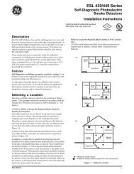
operation See Figure 1 From the keypad, an operator can pan the <strong>CyberDome</strong> 360 o , tilt it<br />
90 o , control its motorized lens, find preset positions, and initiate predefined camera tours<br />
Figure 1: Basic Application<br />
A06-8SG0/B/August2000/1033921B<br />
5
Introduction<br />
<strong>CyberDome</strong> Series <strong>Install</strong>ation Instructions<br />
Cable Requirements<br />
For operation, <strong>CyberDome</strong>s require video, power and data cables as described below:<br />
1) The video cable carries the video signal to the remote viewing site If sending video via<br />
coaxial cable, a 75-ohm coaxial cable is typically used If sending video via twisted-pair<br />
cable, an unshielded, 22 gauge (064 mm) twisted-pair cable is needed<br />
2) The 24VAC cable powers the <strong>CyberDome</strong> and the camera To determine cable size, refer<br />
to the Power Cable Size and Length subsection of the Introduction<br />
3) The RS422 control cable carries commands from the Digiplex keypad to the <strong>CyberDome</strong><br />
An unshielded, two-conductor, twisted-pair cable is required Recommended cable size<br />
is 22 gauge (064 mm)<br />
NOTE: When using the UTP interface modules, the unshielded twisted-pair video and RS422 control<br />
wires can share the same wire jacket, but must remain as separate twisted pairs<br />
Power Requirements<br />
CAUTION!<br />
For optimal video performance, all <strong>CyberDome</strong>s must be powered from an isolated 24 VAC power<br />
source—fused outputs are not adequate Allowable voltage range is 20 to 28 volts<br />
All domes require a 24VAC power supply that provides isolated outputs to operate the domes’<br />
pan/tilt drive, camera, and optional heater/fan (E Option) The total power requirement varies<br />
depending on the model of the <strong>CyberDome</strong><br />
Dome power requirements (at 24VAC):<br />
• All domes without a heater/fan require 16VA<br />
• 7-inch domes with heater/fan require 51VA<br />
• Heavy-duty domes with heater/fan require 91VA<br />
Power Cable Size and Length<br />
It is important to choose the proper gauge of the cable that supplies 24 volts to the <strong>CyberDome</strong><br />
An inadequate gauge will cause a voltage drop resulting in improper operation<br />
Table 1 gives the recommended cable lengths of varying wire gauges for a <strong>CyberDome</strong> with a<br />
color camera Note that the heater and fan (E Option) reduces maximum cable length substantially<br />
Table 1 Recommended maximum cable lengths<br />
Wire Gauge<br />
Maximum Cable Length<br />
All Domes<br />
without Heater/Fan<br />
(16VA)<br />
7-inch Domes<br />
with Heater/Fan<br />
(51VA)<br />
Heavy-duty Domes<br />
with Heater/Fan<br />
(91VA)<br />
(awg) (mm 2 ) Feet Meters Feet Meters Feet Meters<br />
10 2.60 3000 915 900 274 630 192<br />
12 2.05 1900 580 570 174 400 122<br />
14 1.62 1200 365 360 110 250 76<br />
16 1.29 750 230 230 70 160 49<br />
18 1.02 465 142 145 44 100 30<br />
20 0.81 290 90 90 27 62 19<br />
22 0.64 185 56 60 18 40 12<br />
6<br />
A06-8SG0/B/August2000/1033921B
<strong>CyberDome</strong> Series <strong>Install</strong>ation Instructions<br />
Housing <strong>Install</strong>ation<br />
HOUSING INSTALLATION<br />
A complete <strong>CyberDome</strong> consists of an upper<br />
housing, a pan/tilt assembly with a builtin<br />
receiver and camera, and an acrylic dome<br />
See Figure 2<br />
Figure 2: A Complete <strong>CyberDome</strong><br />
In General<br />
The method of installation depends on which<br />
upper housing is being used <strong>Install</strong>ation involves<br />
securing the upper housing, making<br />
cable connections, mounting the pan/tilt assembly,<br />
and fastening the acrylic dome<br />
The Interface Module<br />
All <strong>CyberDome</strong> cable connections (video,<br />
RS422, and 24VAC) are made to one of<br />
several interface modules When sending<br />
video via coaxial cable, connections are made to a coaxial interface module When sending<br />
video via unshielded twisted-pair wire, connections are made to a UTP interface module<br />
There are two CyberMount interface modules—one for coaxial video transmission and one for<br />
UTP video transmission These are integrated into the CyberMount There are also two<br />
<strong>CyberDome</strong> interface modules Again, one for coaxial and one for UTP video transmission<br />
These are used for all other installations, except for the heavy-duty dome Which has its own<br />
integrated coaxial/UTP interface module<br />
CAUTION!<br />
Even though a complete <strong>CyberDome</strong> assembly weighs less than 5 lb (HD less than 15 lb), for<br />
safety reasons Kalatel recommends that all mechanical components used to support the <strong>CyberDome</strong><br />
assembly be able to support a 35 lb (1588 kg) load The heavy-duty dome assembly must be able<br />
to support a 75 lb (3502 kg) load<br />
<strong>Install</strong>ation procedures are listed in separate sections for each housing style Determine<br />
which style is being used and proceed directly to the appropriate section<br />
The upper housing is available in three styles (see Figure 3):<br />
• The flush-mount housing is designed for false ceiling applications Refer to page 8<br />
• The 7-inch (formally 8-inch) pendant-mount housing is designed to suspend from the end<br />
of a 125 in NPT pipe or a variety of arm brackets Refer to page 17<br />
• The heavy-duty housing is designed for areas where the <strong>CyberDome</strong> might be susceptible<br />
to vandalism—it contains its own reinforced mounting bracket Refer to page 28<br />
Figure 3: <strong>CyberDome</strong> Housing Styles<br />
6-inch Flush-mount<br />
Housing<br />
7-inch Pendant-mount<br />
Housing<br />
Heavy-duty<br />
Housing<br />
A06-8SG0/B/August2000/1033921B<br />
7
Housing <strong>Install</strong>ation<br />
<strong>CyberDome</strong> Series <strong>Install</strong>ation Instructions<br />
6-inch Flush-mount Housing <strong>Install</strong>ation<br />
The indoor flush-mount housing can be installed into most types of ceilings, provided there is<br />
sufficient clearance for the unit See Figure 4 The method of installation depends on the type<br />
of ceiling into which the <strong>CyberDome</strong> is being mounted Methods are:<br />
• Method 1 – Into T-bar ceilings (page 8)<br />
• Method 2 – Into non-removable false ceilings (page 11)<br />
• Method 3 – With superstructure attachment (page 15)<br />
Figure 4: False Ceiling Clearance<br />
Method 1: <strong>Install</strong>ation Into T-Bar Ceilings<br />
A T-bar type ceiling consists of a metal grid, which is used to suspend removable panels<br />
See Figure 5 The panels will be either 24 in x 24 in (6096 cm x 6096 cm) or 24 in x 48 in<br />
(6096 cm x 12192 cm) <strong>Install</strong>ation into this type of ceiling requires a KTA-22-6 T-bar Mounting<br />
Panel (24 in x 24 in, ie, 6096 cm x 6096 cm) or a KTA-24-6 T-Bar Support Kit (refer to<br />
Appendix A) The KTA-22-6 was formerly the KTA-00-6, and the KTA-24-6 the KTA-10-6<br />
Figure 5: T-Bar Ceiling with Mounting Panel<br />
8 A06-8SG0/B/August2000/1033921B
<strong>CyberDome</strong> Series <strong>Install</strong>ation Instructions<br />
Housing <strong>Install</strong>ation<br />
For installation, proceed as follows:<br />
CAUTION!<br />
DO NOT provide power to the housing until all installation steps are complete<br />
Step 1)<br />
Step 2)<br />
Step 3)<br />
Step 4)<br />
Determine where the <strong>CyberDome</strong> is to be located and remove the ceiling panel at<br />
that location<br />
If the removed ceiling panel is the smaller 24 in x 24 in (6096 cm x 6096 cm)<br />
size, continue with step 3<br />
If the panel is the larger 24 in x 48 in (6096 cm x 12192 cm) size, cut the panel<br />
into two 24 in x 24 in (6096 cm x 6096 cm) sections and install a 24 in<br />
(6096 cm) T-bar across the center of the ceiling opening Refer to Appendix A:<br />
KTA-24-6 and KTA-24-8/KTA-10-8 T-Bar Support Kits See Figure 5<br />
Feed the video, 24VAC, and RS422 control cables through the ceiling to the<br />
vacated panel location<br />
Prepare the cables as shown in Figure 6<br />
Figure 6: Preparing the Cables<br />
Step 5) Attach the <strong>CyberDome</strong> housing to the KTA-22-6 panel using the three 10-32<br />
flathead screws provided<br />
Step 6) Place the housing/panel assembly in the ceiling<br />
CAUTION!<br />
Each safety cable in step 7 (below) must be able to support a 35 lb (1588 kg) load<br />
Step 7)<br />
Attach two metal safety cables between the KTA-22-6 and the ceiling’s superstructure<br />
to insure that the mounting panel cannot fall See Figure 7 Holes are<br />
located in each side of the panel for this purpose<br />
Figure 7: Attaching the Safety Cables<br />
A06-8SG0/B/August2000/1033921B<br />
9
Housing <strong>Install</strong>ation<br />
<strong>CyberDome</strong> Series <strong>Install</strong>ation Instructions<br />
CAUTION!<br />
DO NOT connect the 24VAC power cable to the video or RS422 connection in step 8 (below), or the<br />
<strong>CyberDome</strong> will be damaged<br />
Step 8)<br />
Step 9)<br />
Connect the prepared cables to the interface module See Figure 8<br />
There are two versions of the <strong>CyberDome</strong> interface module depending on whether<br />
video is being sent via coaxial cable (<strong>CyberDome</strong> Coaxial Interface Module) or<br />
unshielded twisted-pair wire (<strong>CyberDome</strong> UTP Interface Module)<br />
NOTE: When using the <strong>CyberDome</strong> UTP Interface Module, the unshielded twistedpair<br />
video and RS422 control wires can share the same wire jacket, but must remain<br />
as separate twisted pairs<br />
Insert the interconnect cable from the <strong>CyberDome</strong> into the RJ45 jack in the interface<br />
module See Figure 8<br />
Figure 8: Connecting the Cables to Either <strong>CyberDome</strong> Interface Module<br />
Step 10)<br />
Step 11)<br />
Reinstall any removed ceiling panels<br />
Proceed to RS422 Termination on page 31<br />
10 A06-8SG0/B/August2000/1033921B
<strong>CyberDome</strong> Series <strong>Install</strong>ation Instructions<br />
Housing <strong>Install</strong>ation<br />
Method 2: <strong>Install</strong>ation Into A Non-Removable False Ceiling<br />
Note:<br />
This method of installation should be used only when the false ceiling is sturdy enough to support<br />
the weight of a complete <strong>CyberDome</strong> assembly<br />
The KTA-23-6 Ceiling Ring (formerly the KTA-01-6) is used to install the flush-mount housing<br />
in a non-removable type false ceiling The ring allows installation by a single person and does<br />
not require that the person enter the ceiling cavity (except for cable routing)<br />
CAUTION!<br />
The KTA-23-6 distributes the weight of the <strong>CyberDome</strong> around the perimeter of the ceiling cutout<br />
The ceiling must be strong enough to support a minimum of 35 lb (1588 kg), as illustrated in<br />
Figure 9<br />
Figure 9: Minimum Ceiling Strength<br />
To install the upper housing using the KTA-23-6 Ceiling Ring, proceed with the following steps:<br />
CAUTION!<br />
DO NOT provide power to the housing until all installation steps are complete<br />
Step 1)<br />
Step 2)<br />
Hold the ceiling ring in the desired<br />
location on the ceiling with<br />
the flat surface facing away from<br />
the ceiling<br />
Use a pencil to trace the inside<br />
of the ceiling ring and to mark<br />
all five fastener hole locations (as<br />
shown in Figure 10)<br />
Figure 10: Fastener Hole Locations<br />
A06-8SG0/B/August2000/1033921B<br />
11
Housing <strong>Install</strong>ation<br />
<strong>CyberDome</strong> Series <strong>Install</strong>ation Instructions<br />
CAUTION!<br />
Before drilling or cutting holes, be certain there is a minimum of 625 in (1588 cm) of clearance<br />
above all installation holes and that no electrical cables, pipes, or other obstacles are present<br />
Step 3)<br />
Step 4)<br />
Step 5)<br />
Step 6)<br />
Using a 3 ¤16 in drill bit, drill all five fastener holes Be certain that all holes are<br />
drilled perpendicular to the ceiling<br />
Cut a hole in the ceiling using the penciled outline as a guide<br />
Bend the ceiling ring just enough to clear the hole Bend it flat again and place it<br />
in the ceiling with its smooth side down and its mounting holes aligned with the<br />
drilled holes in the ceiling<br />
Using the mounting holes (A in Figure 11), secure the ceiling ring in place with<br />
two of the 6-32 x 2 in flathead screws provided Tighten the screws enough to<br />
draw them flush with the ceiling surface<br />
Figure 11: Mounting the Ceiling Ring<br />
Step 7)<br />
Step 8)<br />
Feed the video, 24VAC, and RS422 control cables from the ceiling through the<br />
hole<br />
Prepare the cables as shown in Figure 12<br />
Figure 12: Preparing the Cables<br />
12 A06-8SG0/B/August2000/1033921B
<strong>CyberDome</strong> Series <strong>Install</strong>ation Instructions<br />
Housing <strong>Install</strong>ation<br />
CAUTION!<br />
The safety cable in step 9 (below) must be able to support a 35 lb (1588 kg) load<br />
Step 9)<br />
Attach a 35 lb (1588 kg) test metal safety cable to the ceiling’s superstructure<br />
and feed it through the hole See Figure 13<br />
Figure 13: Attaching the Safety Cable to the Superstructure<br />
Step 10)<br />
Bring the housing to just below the hole opening and attach the safety cable See<br />
Figure 14<br />
Figure 14: Connecting the Safety Cable to the Housing<br />
A06-8SG0/B/August2000/1033921B<br />
13
Housing <strong>Install</strong>ation<br />
<strong>CyberDome</strong> Series <strong>Install</strong>ation Instructions<br />
CAUTION!<br />
DO NOT connect the 24VAC power cable to the video or RS422 connection in step 11 (below), or the<br />
<strong>CyberDome</strong> will be damaged<br />
Step 11)<br />
Step 12)<br />
Connect the prepared cables to the interface module See Figure 15<br />
There are two versions of the <strong>CyberDome</strong> interface module depending on whether<br />
video is being sent via coaxial cable (<strong>CyberDome</strong> Coaxial Interface Module) or<br />
unshielded twisted-pair wire (<strong>CyberDome</strong> UTP Interface Module)<br />
NOTE: When using the <strong>CyberDome</strong> UTP Interface Module, the unshielded twistedpair<br />
video and RS422 control wires can share the same wire jacket, but must remain<br />
as separate twisted pairs<br />
Insert the interconnect cable from the <strong>CyberDome</strong> into the RJ45 jack in the interface<br />
module See Figure 15<br />
Figure 15: Connecting the Cables to Either <strong>CyberDome</strong> Interface Module<br />
Step 13)<br />
Push the <strong>CyberDome</strong> upper housing through the hole and position the housing’s<br />
three mounting holes to match those in the ceiling Use the remaining three<br />
screws to secure the housing to the ring<br />
Figure 16: Securing the Upper Housing<br />
Step 14)<br />
Proceed to RS422 Termination on page 31<br />
14 A06-8SG0/B/August2000/1033921B
<strong>CyberDome</strong> Series <strong>Install</strong>ation Instructions<br />
Housing <strong>Install</strong>ation<br />
Method 3: <strong>Install</strong>ation By Attaching The Housing To The Superstructure<br />
When a non-removable false ceiling is not sturdy enough to support the weight of the Cyber-<br />
Dome, the housing must be suspended from the ceiling superstructure with metal cables<br />
This normally requires two installers, one to hold the upper housing in place while the second<br />
attaches and tightens the cables in the ceiling cavity Proceed as follows:<br />
CAUTION!<br />
DO NOT provide power to the housing until all installation steps are complete<br />
Step 1)<br />
Determine the desired location on the ceiling for mounting the <strong>CyberDome</strong> and<br />
use a pencil to trace a 6 3 ¤8 in (1619 cm) diameter hole outline<br />
CAUTION!<br />
Before drilling or cutting holes, be certain there is a minimum of 65 in (1651 cm) of clearance<br />
above all installation holes and that no electrical cables, pipes, or other obstacles are present<br />
Step 2)<br />
Step 3)<br />
Cut the hole in the ceiling<br />
Feed the video, 24VAC, and RS422 control cables to the hole location and prepare<br />
them for connection See Figure 17<br />
Figure 17: Preparing the Cables<br />
Step 4)<br />
Push the upper housing<br />
through the hole and attach<br />
securely to the ceiling’s superstructure<br />
with 35 lb<br />
(1588 kg) test cables, as<br />
shown in Figure 18<br />
Figure 18: Attaching the Test Cables<br />
A06-8SG0/B/August2000/1033921B<br />
15
Housing <strong>Install</strong>ation<br />
<strong>CyberDome</strong> Series <strong>Install</strong>ation Instructions<br />
CAUTION!<br />
DO NOT connect the 24VAC power cable to the video or RS422 connection in step 5 (below), or the<br />
<strong>CyberDome</strong> will be damaged<br />
Step 5)<br />
Step 6)<br />
Connect the prepared cables to the interface module See Figure 19<br />
There are two versions of the <strong>CyberDome</strong> interface module depending on whether<br />
video is being sent via coaxial cable (<strong>CyberDome</strong> Coaxial Interface Module) or<br />
unshielded twisted-pair wire (<strong>CyberDome</strong> UTP Interface Module)<br />
NOTE: When using the <strong>CyberDome</strong> UTP Interface Module, the unshielded twistedpair<br />
video and RS422 control wires can share the same wire jacket, but must remain<br />
as separate twisted pairs<br />
Insert the interconnect cable from the <strong>CyberDome</strong> into the RJ45 jack in the interface<br />
module See Figure 19<br />
Figure 19: Connecting the Cables to Either <strong>CyberDome</strong> Interface Module<br />
Step 7)<br />
Proceed to RS422 Termination on page 31<br />
16 A06-8SG0/B/August2000/1033921B
<strong>CyberDome</strong> Series <strong>Install</strong>ation Instructions<br />
Housing <strong>Install</strong>ation<br />
7-inch Pendant-mount Housing <strong>Install</strong>ation<br />
The 7-inch pendant housing can be mounted using one of three methods:<br />
• Method 1 – Suspended from the KTA-20/KTA-20T CyberMount (page 17)<br />
• Method 2 – Suspended from the KTA-21/KTA-21W Swing Mount (page 21)<br />
• Method 3 – Suspended from a 125 in pipe (page 25)<br />
Method 1: CyberMount <strong>Install</strong>ation<br />
The KTA-20/KTA-20T CyberMount suspends the <strong>CyberDome</strong> from a vertical surface<br />
It can be attached directly to the vertical surface or mated with a KTA-25/KTA-25W Cornermount<br />
Bracket, a KTA-26/KTA-26W Pole-mount Bracket, or a KTA-27/KTA-27W Roof-mount<br />
Bracket It provides the path for the video, 24VAC, and RS422 data control cables For instructions<br />
on installing the corner-, pole- or roof-mount brackets, refer to Appendix A: Accessory<br />
<strong>Install</strong>ation<br />
To install the 7-inch pendant housing with the CyberMount, proceed as follows<br />
CAUTION!<br />
DO NOT provide power to the housing until all installation steps are complete<br />
First, mount the CyberMount to a vertical surface:<br />
Step 1)<br />
Step 2)<br />
Step 3)<br />
Step 4)<br />
If a 1/2 in (127 cm) conduit needs to enter the side of the CyberMount, complete<br />
the steps in the KTA-20/KTA-20T CyberMount (Side Conduit Entry) section<br />
of Appendix A: Accessory <strong>Install</strong>ation<br />
Loosen the two CyberMount cover screws enough to remove the cover (removing<br />
the screws is not necessary) See Figure 20<br />
Remove the CyberMount cover and interface module See Figure 20<br />
Place the CyberMount against the vertical mounting surface, ensure that it is<br />
level, and then mark the location of the four mounting holes and the center cableentry<br />
opening See Figure 21<br />
Figure 20 Removing the Cover and Interface<br />
Module of the CyberMount<br />
Figure 21 Marking the Mounting Holes<br />
A06-8SG0/B/August2000/1033921B<br />
17
Housing <strong>Install</strong>ation<br />
<strong>CyberDome</strong> Series <strong>Install</strong>ation Instructions<br />
CAUTION!<br />
For safety, the hardware and procedure used<br />
for securing the CyberMount must allow it to<br />
support a minimum of a 35 lb (1588 kg) load<br />
Figure 22 Minimum Load Requirement for the<br />
CyberMount<br />
Step 5)<br />
Prepare the mounting holes in<br />
accordance with the type of surface<br />
(concrete, wood, etc) and<br />
fasteners used See Figure 22<br />
NOTE: Mounting fasteners are not<br />
included<br />
Step 6)<br />
Step 7)<br />
Step 8)<br />
Step 9)<br />
Drill a pass-through hole in the wall for cable entry, if one does not already exist<br />
Pull the video, 24VAC, and RS422 cables from inside the wall through the<br />
CyberMount cable-entry hole Cut the cables to a length of no shorter than 7 in<br />
(1778 cm)<br />
Securely mount the CyberMount to the wall with the appropriate fasteners See<br />
Figure 22<br />
Properly seal all mounting holes that could cause leaks into the mounting surface<br />
Next, wire and mount the interface module<br />
There are two versions of the CyberMount interface module depending on whether video is<br />
being sent via coaxial cable (CyberMount Coaxial Interface Module) or unshielded twisted-pair<br />
wire (CyberMount UTP Interface Module)<br />
NOTE: When using the CyberMount UTP Interface Module, the unshielded twisted-pair video and<br />
RS422 control wires can share the same wire jacket, but must remain as separate twisted pairs<br />
Step 10)<br />
Prepare the cables as shown in Figure 23<br />
Figure 23: Preparing the Cables<br />
18 A06-8SG0/B/August2000/1033921B
<strong>CyberDome</strong> Series <strong>Install</strong>ation Instructions<br />
Housing <strong>Install</strong>ation<br />
CAUTION!<br />
DO NOT connect the 24VAC power wires to the video or RS422 connections, or the <strong>CyberDome</strong> will<br />
be damaged<br />
Step 11) Wire the interface module (see Figure 24):<br />
a) For power:<br />
Connect the 24VAC wires to the 24VAC terminals on either module<br />
b) For data:<br />
While observing polarity, connect the RS422 control signal twisted-pair wires<br />
to the DATA IN terminals on either module<br />
c) For video:<br />
If sending video via UTP, observe polarity and connect the video twisted-pair<br />
wires to the VIDEO OUT terminals on the UTP module<br />
If sending video via coaxial, connect the BNC to the coaxial module<br />
Figure 24 Connections to Either CyberMount Interface Module<br />
Step 12)<br />
Insert the interface module into its mounting slot up in the CyberMount See<br />
Figure 25<br />
Figure 25 Fitting the Interface Module into the CyberMount<br />
A06-8SG0/B/August2000/1033921B<br />
19
Housing <strong>Install</strong>ation<br />
<strong>CyberDome</strong> Series <strong>Install</strong>ation Instructions<br />
Step 13)<br />
Attach the CyberMount cover<br />
with the hardware provided See<br />
Figure 26<br />
Figure 26 Attaching the CyberMount Cover<br />
Finally, attach the housing to the CyberMount:<br />
Step 14)<br />
Step 15)<br />
Step 16)<br />
Bring the <strong>CyberDome</strong> housing near the end of the CyberMount collar (DO NOT<br />
let go of the housing until after it is secured in step 16) and insert the<br />
<strong>CyberDome</strong> interconnect cable into the RJ45 jack on the interface module See<br />
Figure 27<br />
If installing the optional heater/fan (E option), also connect the heater’s power<br />
cable to the 2-pin Molex connector on the module DO NOT let go of the housing<br />
until after it is secured in step 16 See Figure 27<br />
The fan assembly is attached separately inside the housing to the PTZ assembly<br />
Refer to E Option (Heater/Fan) in Appendix A<br />
Guide the flange of the housing into the collar of the CyberMount (matching up<br />
the mating holes) and fasten the housing to the CyberMount using the three<br />
10-32x1 screws provided See Figure 28<br />
Tighten the screws securely<br />
Figure 27 Connecting the <strong>CyberDome</strong> to the<br />
Interface Module<br />
Figure 28 Fastening the Housing to the<br />
CyberMount<br />
Step 17)<br />
Proceed to RS422 Termination on page 31<br />
20 A06-8SG0/B/August2000/1033921B
<strong>CyberDome</strong> Series <strong>Install</strong>ation Instructions<br />
Housing <strong>Install</strong>ation<br />
Method 2: Swing Mount <strong>Install</strong>ation<br />
The KTA-21/KTA-21W Swing Mount suspends a <strong>CyberDome</strong> from its swinging reach arm,<br />
which is mounted to a rooftop parapet by a mounting bracket It allows the <strong>CyberDome</strong> to<br />
swing out from a building for increased and versatile coverage, and swing in for easy servicing<br />
It provides the path for the video, 24VAC, and RS422 data control cables<br />
To install the 7-inch pendant housing with the Swing Mount, proceed with the following steps<br />
CAUTION!<br />
DO NOT provide power to the housing until all installation steps are complete<br />
Step 1)<br />
Remove the junction box from the mounting plate See Figure 29 below<br />
Figure 29 KTA-21 Assembly Hardware<br />
A06-8SG0/B/August2000/1033921B<br />
21
Housing <strong>Install</strong>ation<br />
<strong>CyberDome</strong> Series <strong>Install</strong>ation Instructions<br />
Step 2)<br />
Step 3)<br />
Place the mounting plate against<br />
the vertical mounting surface,<br />
level the plate, and then mark<br />
the location of the four corner<br />
mounting holes (Use all six<br />
mounting holes for extra support,<br />
as needed) See Figure 30<br />
Prepare the mounting holes in<br />
accordance with the type of surface<br />
(concrete, wood, etc) and<br />
fasteners used<br />
NOTE: Mounting fasteners are not<br />
included<br />
Figure 30 Marking Mounting Holes<br />
CAUTION!<br />
For safety, the hardware and procedure used<br />
for securing the top plate must allow it to support<br />
a minimum of a 35 lb (1588 kg) load<br />
Figure 31 Minimum Load Requirement of Swing<br />
Mount<br />
Step 4)<br />
Step 5)<br />
Attach the mounting plate to the vertical mounting surface with the appropriate<br />
fasteners Make sure the plate is oriented such that the socket is up and the<br />
junction box is down See Figure 31<br />
Properly seal all mounting holes that could cause leaks into the mounting surface<br />
Step 6)<br />
Slide the swing arm into the<br />
mounting socket and securely<br />
tighten the pivot locking screws<br />
See Figure 32 Position the arm<br />
such that the collar is accessible<br />
from the rooftop for mounting the<br />
dome<br />
The swing arm comes with the<br />
cable assembly installed and<br />
tacked down at both ends of the<br />
arm You may have to untack<br />
the end going through the mounting<br />
socket<br />
Figure 32 Placing the Swing Arm in the Mounting<br />
Socket<br />
22 A06-8SG0/B/August2000/1033921B
<strong>CyberDome</strong> Series <strong>Install</strong>ation Instructions<br />
Housing <strong>Install</strong>ation<br />
Step 7)<br />
Step 8)<br />
Feed the end of the cable assembly coming out of the mounting socket through<br />
the nipple on the top of the junction box See Figure 33<br />
Feed the video cable BNC connector through the nipple first, and then the twistedpair<br />
bundle<br />
Remount the junction box onto the mounting plate using the hardware provided<br />
See Figure 34<br />
Figure 33 Cable Assembly into the Chase Nipple<br />
Figure 34 Remounting the Junction Box<br />
Step 9)<br />
Place the sealing gasket on the inside of the junction box cover, and then make<br />
the cable assembly connections to the terminal strip See Figure 35<br />
Figure 35 Cable Assembly Connections in the Junction Box<br />
Step 10)<br />
Step 11)<br />
WITH POWER OFF, make the facilities connections to the terminal strip on the<br />
inside of the junction box cover See Figure 35<br />
<strong>Install</strong> the junction box cover Ensure that the sealing gasket is properly positioned<br />
A06-8SG0/B/August2000/1033921B<br />
23
Housing <strong>Install</strong>ation<br />
<strong>CyberDome</strong> Series <strong>Install</strong>ation Instructions<br />
CAUTION!<br />
DO NOT connect the 24VAC power cable to the video or RS422 connection in step 12 (below), or the<br />
<strong>CyberDome</strong> will be damaged<br />
Step 12)<br />
Attach the interface connector card (provided with the <strong>CyberDome</strong>) to the cable<br />
assembly See Figure 36<br />
There are two versions of the <strong>CyberDome</strong> interface module depending on whether<br />
video is being sent via coaxial cable (<strong>CyberDome</strong> Coaxial Interface Module) or<br />
unshielded twisted-pair wire (<strong>CyberDome</strong> UTP Interface Module)<br />
NOTE: When using the <strong>CyberDome</strong> UTP Interface Module, the unshielded twistedpair<br />
video and RS422 control wires can share the same wire jacket, but must remain<br />
as separate twisted pairs<br />
Figure 36 Swing Mount Connections to Either <strong>CyberDome</strong> Interface Module<br />
Step 13)<br />
Step 14)<br />
Bring the housing near the end of the swing arm and insert the <strong>CyberDome</strong>’s<br />
interconnect cable into the RJ45 jack on the interface module See Figure 36<br />
If installing the optional heater/fan (E Option), also connect the heater’s power<br />
cable to the 2-pin Molex connector on the module See Figure 36<br />
The fan assembly is attached separately inside the housing to the PTZ assembly<br />
Refer to E Option (Heater/Fan) in Appendix A<br />
24 A06-8SG0/B/August2000/1033921B
<strong>CyberDome</strong> Series <strong>Install</strong>ation Instructions<br />
Housing <strong>Install</strong>ation<br />
Step 15)<br />
Push the cables and interface<br />
module back into the swing arm,<br />
guide the flange of the housing<br />
into the collar of the swing arm<br />
(matching up the mating holes),<br />
and fasten the housing to the<br />
swing arm using the three<br />
10-32x3/8 screws provided See<br />
Figure 37<br />
Figure 37 Connecting the Housing to the Swing<br />
Arm<br />
Step 16)<br />
Proceed to RS422 Termination on page 31<br />
After the PTZ assembly and acrylic dome are installed, which starts with the<br />
RS422 termination on page 31, you’ll want to loosen the pivot locking screws on<br />
the mounting socket and swing the swing arm (with <strong>CyberDome</strong> attached) out to<br />
the desired position, and again securely tighten the pivot locking screws<br />
Method 3: Pipe <strong>Install</strong>ation<br />
The 7-inch pendant housing contains a 125 in NPT pipe flange for pipe mounting<br />
Adhere to the following pipe requirements:<br />
• Use only Schedule 40 pipe<br />
• The pipe must be at least 5 in (127 cm) in length to allow for wire connections<br />
• The pipe must be reamed inside at the <strong>CyberDome</strong> end<br />
• The pipe must be able to support a 35 lb (1588 kg) load<br />
• For outdoor applications, Teflon tape must be applied to the pipe to assure that no water<br />
enters the housing<br />
To install the 7-inch pendant housing onto a threaded pipe, proceed with the following steps:<br />
CAUTION!<br />
DO NOT provide power to the housing until all installation steps are complete<br />
Step 1)<br />
Step 2)<br />
Step 3)<br />
Securely mount the pipe from which the pendant housing will be suspended<br />
Remember that the pipe must be able to support a 35 lb (1588 kg) load<br />
Feed the video, 24 VAC, and RS422 control cables through the pipe<br />
Prepare the cables as shown in Figure 38<br />
Figure 38: Preparing the Cables<br />
A06-8SG0/B/August2000/1033921B<br />
25
Housing <strong>Install</strong>ation<br />
<strong>CyberDome</strong> Series <strong>Install</strong>ation Instructions<br />
CAUTION!<br />
DO NOT connect the 24VAC power cable to the video or RS422 connection in step 4 (below), or the<br />
<strong>CyberDome</strong> will be damaged<br />
Step 4)<br />
Make the cable connections to the interface module See Figure 39 Allow approximately<br />
3 inches (762 cm) of cable for connections<br />
There are two versions of the <strong>CyberDome</strong> interface module depending on whether<br />
video is being sent via coaxial cable (<strong>CyberDome</strong> Coaxial Interface Module) or<br />
unshielded twisted-pair wire (<strong>CyberDome</strong> UTP Interface Module)<br />
NOTE: When using the <strong>CyberDome</strong> UTP Interface Module, the unshielded twistedpair<br />
video and RS422 control wires can share the same wire jacket, but must remain<br />
as separate twisted pairs<br />
Figure 39: Pipe Connections to Either <strong>CyberDome</strong> Interface Module<br />
Step 5)<br />
If the housing is being installed<br />
outdoors, install the water-sealing<br />
rubber boot (Figure 40):<br />
a) Spray soapy water onto the<br />
pipe<br />
b) Slide the rubber boot up the<br />
pipe<br />
c) Apply Teflon tape to the pipe<br />
threads<br />
NOTE: Teflon tape must be applied<br />
as the first layer of protection<br />
Figure 40: Water-sealing Rubber Boot<br />
26 A06-8SG0/B/August2000/1033921B
<strong>CyberDome</strong> Series <strong>Install</strong>ation Instructions<br />
Housing <strong>Install</strong>ation<br />
Step 6)<br />
Step 7)<br />
Bring the housing near the end of the pipe and insert the <strong>CyberDome</strong>’s interconnect<br />
cable into the RJ45 jack on the interface module See Figure 39<br />
If installing the optional heater/fan (E option), also connect the heater’s power<br />
cable to the 2-pin Molex connector on the module See Figure 39<br />
The fan assembly is attached separately inside the housing to the PTZ assembly<br />
Refer to E Option (Heater/Fan) in Appendix A<br />
Step 8)<br />
Step 9)<br />
Step 10)<br />
Step 11)<br />
Push the cables and interface<br />
module back into the pipe<br />
Before threading the housing<br />
onto the pipe, rotate it five turns<br />
in the counterclockwise direction<br />
(as viewed from below) to allow<br />
for cable twist Turn the housing<br />
onto the pipe in a clockwise direction<br />
until it is tightened securely<br />
See Figure 41 Check to<br />
be certain that it is not cross<br />
threaded<br />
Slide the rubber boot down the<br />
pipe and fit it securely over the<br />
housing’s flange<br />
Proceed to RS422 Termination<br />
on page 31<br />
Figure 41: Threading the Housing<br />
A06-8SG0/B/August2000/1033921B<br />
27
Housing <strong>Install</strong>ation<br />
<strong>CyberDome</strong> Series <strong>Install</strong>ation Instructions<br />
Heavy-duty Housing (<strong>CyberDome</strong> HD) <strong>Install</strong>ation<br />
The <strong>CyberDome</strong> HD is enclosed in a tamper-resistant aluminum housing with an impactresistant<br />
acrylic dome Attached to the housing is a reinforced swivel-mount bracket It is<br />
designed to mount against a hard surface, but will also mate with a KTA-25/KTA-25W Cornermount<br />
Bracket or a KTA-26/KTA-26W Pole-mount Bracket For instructions on using the<br />
corner- or pole-mount brackets, refer to Appendix A: Accessory <strong>Install</strong>ation<br />
CAUTION!<br />
DO NOT provide power to the housing until all installation steps are complete<br />
To install and mount the <strong>CyberDome</strong> HD directly to a hard surface (such as concrete), proceed<br />
with the following steps:<br />
Step 1)<br />
Locate the carriage bolts that secure the upper housing to the swivel-mount<br />
bracket See Figure 42 Loosen and remove the ESNA nuts (inside the upper<br />
housing), remove the carriage bolts, and detach the upper housing<br />
Figure 42: Removing the Carriage Bolts<br />
CAUTION!<br />
DO NOT mount the heavy-duty <strong>CyberDome</strong> HD via the small mounting holes alone They are for<br />
additional security where needed<br />
Step 2)<br />
Step 3)<br />
Using the swivel-mount bracket as a template, mark the mounting surface where<br />
the <strong>CyberDome</strong> HD is to be installed See Figure 43 Mark the four large mounting<br />
slots For additional security, also mark the four small mounting holes<br />
Drill the four (or eight) holes into the mounting surface<br />
28 A06-8SG0/B/August2000/1033921B
<strong>CyberDome</strong> Series <strong>Install</strong>ation Instructions<br />
Housing <strong>Install</strong>ation<br />
CAUTION!<br />
For safety, use the appropriate fasteners for the surface that the bracket is being mounted to that will<br />
support a 75 lb (3502 kg) load<br />
Step 4) Secure the swivel mount bracket to the mounting surface (Figures 43 and 44)<br />
Figure 43: Mounting the Bracket<br />
Figure 44: <strong>CyberDome</strong> HD Minimum Load<br />
Requirement<br />
Step 5)<br />
Step 6)<br />
Reattach the upper housing to the swivel-mount bracket Position the angle of<br />
the housing so that its top surface is level Reinstall the carriage bolts and tighten<br />
the ESNA nuts<br />
Assemble an appropriate external 1/2 in (127 cm) flexible conduit to enter the<br />
housing and carry in the RS422, 24VAC and video cables through the cable entry<br />
hole See Figure 45<br />
• Use a 90° connector to allow the housing to swivel while attached<br />
• Use a watertight flexible conduit for installations where the <strong>CyberDome</strong> HD<br />
may be exposed to moisture or precipitation<br />
Figure 45: Flexible Cable Conduit<br />
A06-8SG0/B/August2000/1033921B<br />
29
Housing <strong>Install</strong>ation<br />
<strong>CyberDome</strong> Series <strong>Install</strong>ation Instructions<br />
Step 7)<br />
Thread the RS422, 24VAC, and video cable through the flexible conduit, and<br />
prepare them as shown in Figure 45 Feed the cables into the upper housing,<br />
leaving approximately 4 in (1016 cm) of slack, and attach the conduit to the<br />
housing with a locking nut<br />
CAUTION!<br />
If the power and RS422 cables are reversed in step 8 (below), the <strong>CyberDome</strong> will be damaged<br />
Step 8)<br />
Locate the interface module mounted in the upper housing See Figure 46 Connect<br />
the 24VAC, RS422, and video cables to the interface module as shown<br />
Figure 46: Heavy-Duty Housing Cable Connections<br />
Step 9)<br />
Proceed to RS422 Termination on page 31<br />
30 A06-8SG0/B/August2000/1033921B
<strong>CyberDome</strong> Series <strong>Install</strong>ation Instructions<br />
PTZ and Dome <strong>Install</strong>ation<br />
PTZ AND DOME INSTALLATION<br />
RS422 Termination<br />
Step 1)<br />
Step 2)<br />
Step 3)<br />
Locate the red, sliding termination switch on the PC card at the top of the housing<br />
See Figure 47<br />
If the RS422 control cable connected to the <strong>CyberDome</strong> does not loop out to<br />
another unit (ie, it is the final receiver location), place the switch in the ON<br />
position (as shown in Figure 47)<br />
Apply 24 VAC power to the housing The housing’s red LED power indicator lamp<br />
should illuminate It is located on the underside of the PTZ bracket<br />
Figure 47: Line Termination Switch on PC Card<br />
<strong>Install</strong>ing the Pan/Tilt Assembly<br />
This section gives detailed procedures for installing the <strong>CyberDome</strong>’s motorized pan/tilt<br />
assembly <strong>Install</strong>ation involves securing the pan/tilt assembly to the upper housing and setting<br />
the receiver’s DIP switch<br />
NOTE: The pan/tilt assembly may be installed while power is applied to the housing<br />
Proceed as follows:<br />
Step 1)<br />
Insert the safety catch (A) though the channel in the retaining bracket (B)<br />
attached to the upper housing See Figure 48<br />
Note:<br />
When completing the next step, the <strong>CyberDome</strong> will move (become active) momentarily in both the<br />
pan and tilt directions, as part of its orientation protocol<br />
Step 2)<br />
Step 3)<br />
Push the spring latch handle (C) outward, while pivoting the pan/tilt assembly up<br />
until it is vertical Secure the pan/tilt assembly by releasing the latch handle and<br />
engaging the catch tab (D) See Figure 48<br />
Check to ensure that the four mounting nuts (E) are mated with the four alignment<br />
holes (F) See Figure 48<br />
A06-8SG0/B/August2000/1033921B<br />
31
PTZ and Dome <strong>Install</strong>ation<br />
<strong>CyberDome</strong> Series <strong>Install</strong>ation Instructions<br />
Figure 48: <strong>Install</strong>ing the Pan/Tilt Assembly<br />
Note the following change to the PTZ<br />
assembly:<br />
<strong>CyberDome</strong>s are now fitted with plastic mounting<br />
nuts (E in Figure 48), instead of metal<br />
acorn nuts<br />
Rubber grommets are not used with the plastic<br />
nuts See Figure 49 Use rubber grommets<br />
only when metal acorn nuts are present on<br />
the PTZ assembly<br />
Figure 49: Improved Alignment Connection<br />
32 A06-8SG0/B/August2000/1033921B
<strong>CyberDome</strong> Series <strong>Install</strong>ation Instructions<br />
PTZ and Dome <strong>Install</strong>ation<br />
Setting the Site Address DIP Switch<br />
The receiver card mounted on the <strong>CyberDome</strong>’s pan/tilt assembly contains a multi-position<br />
DIP switch See Figure 50 The switch is used to assign the <strong>CyberDome</strong> a site number in the<br />
Digiplex system<br />
Figure 50: Location of Site Address DIP Switch<br />
To enter the receiver’s site number on the DIP switch:<br />
Step 1)<br />
Step 2)<br />
Determine which position values must be added together to equal the site number<br />
See Table 2 and Figure 51<br />
Place the switches that correspond to those values in the ON position<br />
Table 2 DIP Switch Positions and Equivalent Values<br />
DIP Switch Position Number 1 2 3 4 5 6 7 8 9 10 11 12<br />
Equivalent Value 1 2 4 8 16 32 64 128 256 512 X X<br />
X = Not Used<br />
Figure 51: Building Site Addresses<br />
A06-8SG0/B/August2000/1033921B<br />
33
PTZ and Dome <strong>Install</strong>ation<br />
<strong>CyberDome</strong> Series <strong>Install</strong>ation Instructions<br />
<strong>Install</strong>ing the Dome Assembly<br />
The <strong>CyberDome</strong> comes with one of four acrylic dome assembly options: clear, tinted, smoked,<br />
chrome mirrored and gold mirrored domes Each dome assembly attaches to the upper<br />
housing with interlocking clips and a dome safety cable<br />
CAUTION!<br />
DO NOT touch the acrylic when handling the dome assembly Use a scratch-resistant cloth<br />
To attach the dome assembly to flush- and pendant-mount housings:<br />
Step 1)<br />
Step 2)<br />
Step 3)<br />
Fasten the dome safety cable to the upper housing with the safety clip See<br />
Figure 52<br />
Position the dome such that the angled ends of its mounting clips face the angled<br />
ends of the clips attached to the upper housing<br />
Turn the acrylic dome clockwise, so that the ends of the mounting clips engage<br />
and lock into place<br />
Figure 52: Attaching the Dome Assembly to the Upper Housing<br />
34 A06-8SG0/B/August2000/1033921B
<strong>CyberDome</strong> Series <strong>Install</strong>ation Instructions<br />
PTZ and Dome <strong>Install</strong>ation<br />
To attach the dome assembly to the heavy-duty <strong>CyberDome</strong> housing:<br />
Step 1)<br />
Step 2)<br />
Step 3)<br />
Fasten the dome safety cable to the upper housing with the safety clip See<br />
Figure 52<br />
Locate the mounting tabs on the dome plate and insert them into the mounting<br />
slots on the upper housing<br />
Lock the dome in place with the keylock latch<br />
<strong>Install</strong>ation is now complete<br />
Programming and Operating the <strong>CyberDome</strong><br />
Note:<br />
To ensure that unit(s) are operating properly, test the pan, tilt and lens functions once each week<br />
<strong>CyberDome</strong>s come equipped with a variety of camera options and each camera’s programming<br />
varies depending on available functions Refer to the <strong>CyberDome</strong> Programming Instructions<br />
manual for programming instructions for any <strong>CyberDome</strong><br />
<strong>CyberDome</strong>s are controlled from either of Kalatel’s KTD-404/304 or KTD-400/300 controller<br />
keypads Refer to the corresponding keypad manual for instructions on operating all<br />
<strong>CyberDome</strong>s<br />
A06-8SG0/B/August2000/1033921B<br />
35
PTZ and Dome <strong>Install</strong>ation<br />
<strong>CyberDome</strong> Series <strong>Install</strong>ation Instructions<br />
36 A06-8SG0/B/August2000/1033921B
<strong>CyberDome</strong> Series <strong>Install</strong>ation Instructions<br />
Appendix A: Accessory <strong>Install</strong>ation<br />
APPENDIX A: ACCESSORY INSTALLATION<br />
KTA-25/KTA-25W Corner Adapter<br />
The KTA-25/KTA-25W Corner-mount Bracket (formerly KTA-06-12) is used to mount a<br />
KTA-02-12W Wall-mount Bracket or KTA-20/KTA-20T CyberMount to the corner of a building<br />
See Figure 53<br />
CAUTION!<br />
For safety, the hardware and procedure used for securing the KTA-25/25W must allow it to support<br />
a minimum of a 35 lb (1588 kg) load<br />
Step 1)<br />
Step 2)<br />
Step 3)<br />
Step 4)<br />
Place the adapter on the corner<br />
of the building and mark the location<br />
of the four mounting holes<br />
See Figure 53<br />
Prepare the four mounting holes<br />
in accordance with the type of<br />
wall (eg, concrete, wood) and<br />
fasteners used<br />
Secure the adapter to the wall<br />
with the appropriate fasteners<br />
Attach the KTA-02-12W Wall<br />
Bracket to the adapter using the<br />
hardware provided<br />
Figure 53: Corner Adapter <strong>Install</strong>ation<br />
KTA-26/KTA-26W Pole Adapter<br />
The KTA-26/KTA-26W Pole-mount Bracket (formerly KTA-07-12) is used to adapt a KTA-02-12W<br />
Wall-mount Bracket or KTA-20/KTA-20T CyberMount to a pole The bracket can be bolted to<br />
the pole or secured with adjustable stainless-steel bands See Figure 54<br />
CAUTION!<br />
For safety, the hardware and procedure used for securing the KTA-26/26W must allow it to support<br />
a minimum of a 35 lb (1588 kg) load<br />
Figure 54: Pole Adapter <strong>Install</strong>ation<br />
A06-8SG0/B/August2000/1033921B<br />
37
Appendix A: Accessory <strong>Install</strong>ation<br />
<strong>CyberDome</strong> Series <strong>Install</strong>ation Instructions<br />
KTP-24 Power Supply<br />
The KTP-24 (formerly KTA-04-12) is a 24VAC outdoor power supply designed for use with a<br />
pendant-mount weatherproof <strong>CyberDome</strong> It provides enough power (100VA) to operate the<br />
dome’s pan/tilt drive, camera, and heater/fan The KTP-24 can be attached directly to a wall,<br />
or it can be mounted on to either the KTA-25/KTA-25W Corner-mount Bracket or the KTA-26/<br />
KTA-26W Pole-mount Bracket Fasteners are provided for all applications<br />
Step 1)<br />
Step 2)<br />
Step 3)<br />
Step 4)<br />
Loosen the unit’s four watertight screws and remove the cover<br />
When attaching the KTP-24 to<br />
a KTA-25/KTA-25W or KTA-26/<br />
KTA-26W, proceed to step 4<br />
When attaching it directly to a<br />
wall, mark the location of the four<br />
mounting holes using the dimensions<br />
shown in Figure 55<br />
Prepare the four mounting holes<br />
in accordance with the type of<br />
wall (eg, concrete, wood) and<br />
fasteners<br />
Mount the KTP-24 with the appropriate<br />
fasteners directly to the<br />
wall, or to the KTA-25/KTA-25W<br />
or KTA-26/KTA-26W brackets<br />
(as shown in Figure 56)<br />
Figure 55: KTP-24 Cover and Mounting Holes<br />
Figure 56: Mounting the KTP-24 to the Corner- and Pole-mount Brackets<br />
Step 5)<br />
Make the cable connections as shown in Figure 57<br />
Figure 57: KTP-24 Cable Connections<br />
Step 6)<br />
Replace the cover and tighten the screws securely to ensure a watertight seal<br />
38 A06-8SG0/B/August2000/1033921B
<strong>CyberDome</strong> Series <strong>Install</strong>ation Instructions<br />
Appendix A: Accessory <strong>Install</strong>ation<br />
KTP-24-8 Multiple Output Power Supply<br />
The KTP-24-8 is a compact and durable power supply that provides eight isolated 24VAC<br />
outputs for indoor applications Each output can power devices requiring 1 amp or less The<br />
unit is equipped with automatic resettable fuses for each output and is powered from a standard<br />
115 or 230VAC source<br />
CAUTION!<br />
The KTP-24-8 was designed for indoor applications only For outdoor units with a heater/fan, use<br />
the KTP-24 Outdoor Power Supply<br />
Note:<br />
The KTP-24-8 can also be mounted in a rack using the KTP-24-00 Rack Mount Kit accessory<br />
Step 1) Mount the unit using the slots provided<br />
Step 2) Make cable connections to the KTP-24-8 as shown in Figure 58 Refer to Table 1<br />
(page 6) for suitable cable gauge sizes when connecting the output cables<br />
Figure 58: KTP-24-8 Cable Connections<br />
Operation<br />
Each 24VAC output of the power supply has a resettable fuse that will trip if the current draw<br />
exceeds one amp In this event, the device on that output may operate intermittently, or not at<br />
all The fuse will automatically reset itself when the load is removed from the output<br />
CAUTION!<br />
DO NOT reconnect any device that caused an output fuse to trip, until the device has been inspected<br />
and determined to be in proper working condition<br />
A06-8SG0/B/August2000/1033921B<br />
39
Appendix A: Accessory <strong>Install</strong>ation<br />
<strong>CyberDome</strong> Series <strong>Install</strong>ation Instructions<br />
KTA-27/KTA-27W Roof-mount Adapter<br />
The KTA-27/KTA-27W Roof-mount Adapter (formerly KTA-09-12) is designed to combine with<br />
the KTA-02-12W Wall-mount Bracket or KTA-20/KTA-20T CyberMount on the roof or parapet<br />
of a building The Roof-mount Adapter is hinged to allow the <strong>CyberDome</strong> to pivot over the roof<br />
for safe servicing<br />
Step 1)<br />
Step 2)<br />
Step 3)<br />
Step 4)<br />
Remove the cover screw from the top of the KTA-27/KTA-27W and open the<br />
bracket See Figure 59<br />
Locate the six mounting slots on the base of the bracket See Figures 59 and 60<br />
Place the Roof-mount Adapter on the edge of the roof or parapet, and mark the<br />
location of the mounting slots See Figures 59 and 60<br />
Prepare the mounting slots in accordance with the type of wall (eg, concrete,<br />
wood) and fasteners used<br />
CAUTION!<br />
For safety, the hardware and procedure used for securing the KTA-27/27W must allow it to support<br />
a minimum of a 35 lb (1588 kg) load<br />
Step 5)<br />
Step 6)<br />
Secure the adapter to the roof or parapet with the appropriate fasteners<br />
Properly seal all mounting holes that could cause leaks into the roof structure<br />
Figure 59 Roof-mount Adapter <strong>Install</strong>ation<br />
Figure 60 Base of Roof-mount Adapter<br />
40 A06-8SG0/B/August2000/1033921B
<strong>CyberDome</strong> Series <strong>Install</strong>ation Instructions<br />
Appendix A: Accessory <strong>Install</strong>ation<br />
Step 7)<br />
Step 8)<br />
Step 9)<br />
Step 10)<br />
Route the power, RS422, and video cables through the KTA-09-12, leaving enough<br />
cable to attach the cables to the inside of the roof-mount adapter and continue<br />
them through the KTA-02-12W and into the camera housing<br />
Attach the KTA-02-12W Wall-mount Bracket to the roof-mount adapter See Figure<br />
59<br />
Attach the pendant-mount housing to the KTA-02-12W according to the instructions<br />
given on page 49<br />
Close the KTA-09-12 and secure it with the cover screw<br />
KTA-24-6 and KTA-10-8 T-bar Support Kits<br />
The KTA-24-6 and KTA-10-8 are T-bar support kits for mounting one KTA-series flush-mount<br />
dome in an existing ceiling panel KTA-24-6 is for 6-inch flush-mount housings and KTA-10-8<br />
is for 8-inch flush-mount housings The T-bar support kit distributes the weight of the dome to<br />
the panel braces via support brackets Each kit comes with one ceiling ring and mounting<br />
hardware<br />
Step 1)<br />
Step 2)<br />
Step 3)<br />
Step 4)<br />
Step 5)<br />
Step 6)<br />
Remove the T-bar ceiling panel<br />
Hold the ceiling ring in the desired location on the tile with the flat surface facing<br />
away from the panel<br />
Use a pencil to trace the inside of the ceiling ring and to mark all five fastener hole<br />
locations (as shown in Figure 11 on page 11)<br />
Using a 3 ¤16” drill bit, drill all five fastener holes Be certain that all holes are drilled<br />
perpendicular to the panel<br />
Cut a hole in the panel using the penciled outline as a guide<br />
Place the T-bar support brackets flush against the inside of the panel, with the<br />
long sides flat and the short sides vertical Align the mounting holes with the<br />
drilled holes in the panel See Figure 61<br />
Figure 61: <strong>Install</strong>ing the T-bar Support Kit with Ceiling Ring<br />
A06-8SG0/B/August2000/1033921B<br />
41
Appendix A: Accessory <strong>Install</strong>ation<br />
<strong>CyberDome</strong> Series <strong>Install</strong>ation Instructions<br />
Step 7)<br />
Step 8)<br />
Step 9)<br />
Step 10)<br />
Place the ceiling ring on the T-bar brackets with its smooth side down and its<br />
mounting holes aligned with the mounting holes on the brackets See Figure 61<br />
Using the mounting holes (A), secure the ceiling ring in place with two of the<br />
6-32x2 in flathead screws provided Tighten the screws enough to draw them<br />
flush with the panel surface<br />
Replace the T-bar ceiling panel with the attached T-bar support kit in its original<br />
location Attach the T-bar support to the panel braces using the holes provided<br />
(see Figure 61)<br />
To install the housing, proceed as described on page 8<br />
E Option (Heater/Fan)<br />
The E Option heater/fan is available for the 7-inch weatherproof outdoor pendant-mount dome<br />
and the 8-inch tamper-resistant, heavy-duty aluminum dome The fan for the <strong>CyberDome</strong> is<br />
packaged separately for shipment The heater pad comes attached to the ceiling of the housing<br />
and its power cable was connected during housing installation<br />
CAUTION!<br />
One power input is used for both the <strong>CyberDome</strong> and the heater/fan The size and length of the<br />
power cable must be carefully determined as directed on page 6 of this manual If the cable used is<br />
too small, the voltage drop across the power line may be excessive and affect the operation of the<br />
<strong>CyberDome</strong> The total power draw for the <strong>CyberDome</strong> and heater/fan is 51VA for the 7-inch weatherproof<br />
housing, and 91VA for the 8-inch heavy-duty housing<br />
To install the fan onto the <strong>CyberDome</strong> pan/tilt mechanism:<br />
Step 1)<br />
Step 2)<br />
Step 3)<br />
Step 4)<br />
Step 5)<br />
Remove the <strong>CyberDome</strong> pan/tilt mechanism and fan assembly from their packaging<br />
Locate the two 4-40 x 1/4” screws shipped with the fan assembly<br />
Position the fan assembly (as shown in Figure 62) and fasten it to the pan/tilt<br />
mechanism using the two 4-40 x 1/4” screws<br />
Plug the fan motor into the side PC card See Figure 62<br />
Before installing the unit into the weatherproof or tamper-resistant housing, determine<br />
the appropriate size and length of the power cable by referring to Table 1<br />
(Maximum Cable Length) on page 6<br />
Figure 62: <strong>Install</strong>ing the E Option Heater/Fan<br />
42 A06-8SG0/B/August2000/1033921B
<strong>CyberDome</strong> Series <strong>Install</strong>ation Instructions<br />
Appendix A: Accessory <strong>Install</strong>ation<br />
KTA-20/KTA-20T CyberMount (Side Conduit Entry)<br />
Cabling will usually come out of the mounting surface and enter the CyberMount through the<br />
rear opening in the base For those applications where cabling is running along the mounting<br />
surface and needs to enter the CyberMount through the side, these instructions are provided<br />
for punching a hole that will accommodate a 1/2” conduit<br />
Step 1)<br />
Step 2)<br />
Step 3)<br />
Step 4)<br />
Loosen the two CyberMount cover screws enough to remove the cover (removing<br />
the screws is not necessary) See Figure 63<br />
Remove the CyberMount cover and interface module See Figure 63<br />
Align the template with the side of the CyberMount See Figure 64<br />
Mark the center of the template’s drill hole See Figure 64<br />
Figure 63: Removing the Cover and Interface<br />
Module of the CyberMount<br />
Figure 64: Aligning the Template and Marking<br />
the Drill Hole<br />
CAUTION!<br />
To maintain material integrity, DO NOT drill the conduit hole Start with a pilot hole and enlarge it until<br />
a knockout punch can be used to achieve the final hole size (Hole sizes are given below)<br />
Step 5)<br />
Step 6)<br />
Step 7)<br />
First, drill a 1/8 in (32 cm) pilot hole See Figure 65<br />
Next, enlarge the pilot hole to 3/8 in (95 cm)<br />
Finally, use a 1/2 in (127 cm) conduit knockout punch to enlarge the hole to<br />
7/8 in (222 cm)<br />
Figure 65: Drilling and Punching the Conduit Hole<br />
A06-8SG0/B/August2000/1033921B<br />
43
Appendix A: Accessory <strong>Install</strong>ation<br />
<strong>CyberDome</strong> Series <strong>Install</strong>ation Instructions<br />
44 A06-8SG0/B/August2000/1033921B
<strong>CyberDome</strong> Series <strong>Install</strong>ation Instructions<br />
Appendix B: Handling Mirrored Domes<br />
APPENDIX B: MIRRORED DOME HANDLING<br />
CAUTION!<br />
For warranty protection, read and adhere to the following dome handling instructions carefully<br />
The inside surface of a chrome or gold dome is easily scratched Please use the following<br />
precautions to maintain the dome’s surface<br />
A) Never touch the inside surface of a mirrored dome with bare hands The acid<br />
from your fingers will etch the mirrored coating Wear cotton gloves while handling the<br />
dome If fingerprints accidentally get on the dome’s interior surface, immediately and<br />
carefully remove them according to the recommended cleaning procedure outlined in<br />
step E below<br />
B) Always handle the dome from the outside of its circular flange<br />
C) To remove dust and other surface contaminants from the dome’s interior:<br />
Use clean dry pressurized air to gently blow off loose contaminants<br />
D) To remove heavier contaminants that cannot be removed with pressurized air:<br />
Rinse the dome with water and immediately dry it with clean dry pressurized air (to<br />
prevent water spots) Avoid wiping the coated surface—it is easily abraded Once<br />
scratched, the dome cannot be recoated<br />
E) To clean residue that requires internal wiping:<br />
DO NOT rub the inside of the dome by hand Instead, make and use a “wick” as<br />
follows:<br />
n Only use “Microwave Bounty” or an equivalent soft brand of paper towel<br />
n Roll a section of paper towel into a tightly wound tube; tear the tube in half; and wet<br />
the fuzzy end of this wick with 75% standard rubbing or isopropyl alcohol<br />
n Holding the dome with its opening facing downward, wipe the interior of the dome<br />
with the wick (held at its dry end) using a circular motion starting from the outside<br />
and spiraling into the center<br />
n Use a new wick for each two passes over the dome<br />
F) To clean the exterior of the dome:<br />
Use any nonabrasive cleaning cloth and cleaning agent that is safe for use on acrylic<br />
plastic Either liquid or spray cleaner/wax suitable for fine furniture is acceptable<br />
A06-8SG0/B/August2000/1033921B<br />
45
Appendix B: Handling Mirrored Domes<br />
<strong>CyberDome</strong> Series <strong>Install</strong>ation Instructions<br />
46 A06-8SG0/B/August2000/1033921B
<strong>CyberDome</strong> Series <strong>Install</strong>ation Instructions<br />
Appendix C: 8-inch Pendant-mount Housing <strong>Install</strong>ation<br />
APPENDIX C: 8-INCH PENDANT HOUSING INSTALLATION<br />
The pendant housing can be mounted using one of two methods:<br />
• Method 1 – Suspended from a 125 in pipe (page 47)<br />
• Method 2 – Attached to a KTA-02-12 Wall Bracket (page 49)<br />
Method 1: Pipe <strong>Install</strong>ation<br />
The pendant housing contains a 125 in NPT pipe flange for pipe mounting<br />
Adhere to the following pipe requirements:<br />
• Use only Schedule 40 pipe<br />
• The pipe must be at least 5 in (127 cm) in length to allow for wire connections<br />
• The pipe must be reamed inside at the <strong>CyberDome</strong> end<br />
• The pipe must be able to support a 35 lb (1588 kg) load<br />
• For outdoor applications (W option), thread sealer must be applied to the pipe to assure<br />
that no water enters the housing<br />
To install the pendant housing, proceed with the following steps:<br />
CAUTION!<br />
DO NOT provide power to the housing until all installation steps are complete<br />
Step 1)<br />
Step 2)<br />
Securely mount the pipe from<br />
which the pendant housing will<br />
be suspended Remember<br />
that the pipe must be able to<br />
support a 35 lb (1588 kg)<br />
load<br />
Feed the video, 24VAC, and<br />
RS422 control cables through<br />
the pipe<br />
Figure 66: Preliminary Cable Connections<br />
CAUTION!<br />
If the power and RS422 cables are reversed<br />
in step 3 (below), the <strong>CyberDome</strong> will be damaged<br />
Step 3)<br />
Make the cable connections<br />
to the interface module (see<br />
Figure 23) Allow approximately<br />
3” (762 cm) of cable<br />
for connection<br />
If installing a weatherproof<br />
housing with a heater/fan<br />
E Option, also connect the<br />
heater’s power cable to the<br />
2-pin Molex connector on the<br />
interface connector card<br />
A06-8SG0/B/August2000/1033921B<br />
47
Appendix C: 8-inch Pendant-mount Housing <strong>Install</strong>ation<br />
<strong>CyberDome</strong> Series <strong>Install</strong>ation Instructions<br />
Step 4)<br />
Step 5)<br />
If the housing is being installed<br />
outside (W option only), apply<br />
thread sealer to the pipe<br />
to assure that no water enters<br />
the housing<br />
Bring the housing near the end<br />
of the pipe and insert the interconnect<br />
cable from the interface<br />
connector card into<br />
the RJ45 jack (as shown in Figure<br />
67)<br />
Figure 67: Inserting the Interconnect Cable<br />
Step 6)<br />
Step 7)<br />
While pushing the cables and interface connector card back into the pipe, position<br />
the housing where it can be threaded onto the pipe<br />
Before threading the housing onto the pipe, rotate it five turns in the counterclockwise<br />
direction (as viewed from below) to allow for cable twist Turn the housing<br />
onto the pipe in a clockwise direction until it is tightened securely See Figure 68<br />
Check to be certain that it is not cross threaded<br />
Figure 68: Threading the Housing<br />
CAUTION!<br />
DO NOT undertighten or overtighten the top housing nuts Leakage or stripped material will result<br />
Step 8)<br />
Step 9)<br />
Using a 3/8-inch nut driver or socket wrench, securely tighten the three mounting<br />
nuts on top of the housing to a torque of 3 to 5 ft-lb See Figure 67 (above)<br />
Proceed to RS422 Termination on page 31<br />
48 A06-8SG0/B/August2000/1033921B
<strong>CyberDome</strong> Series <strong>Install</strong>ation Instructions<br />
Appendix C: 8-inch Pendant-mount Housing <strong>Install</strong>ation<br />
Method 2: Wall Bracket <strong>Install</strong>ation<br />
The <strong>CyberDome</strong> can be mounted using the KTA-02-12 Wall Bracket, which supports the<br />
dome and provides a path for the video, 24VAC, and RS422 control cables The wall bracket is<br />
designed to mount against a hard surface, but will also mate with a KTA-25/KTA-25W Cornermount<br />
Bracket, a KTA-26/KTA-26W Pole-mount Bracket, or a KTA-27/KTA-27W Roof-mount<br />
Bracket For instructions on installing the corner-, pole- or roof-mount brackets, refer to Appendix<br />
A: Accessory <strong>Install</strong>ation A 3 ¤8 in nut driver and Phillips screw driver are required for<br />
installation Proceed with the following steps<br />
CAUTION!<br />
DO NOT provide power to the housing until all installation steps are complete<br />
Step 1)<br />
Loosen the two screws that hold the bracket’s cover, lift the cover and remove<br />
See Figure 69<br />
Figure 69: KTA-02-12 Wall Bracket<br />
Mounting Plate<br />
Step 2)<br />
Step 3)<br />
Step 4)<br />
Place the bracket’s mounting plate against the wall and mark the location of the<br />
four mounting holes and the cable entry hole<br />
Prepare the four mounting holes in accordance with the type of wall (eg, concrete,<br />
wood) and fasteners used<br />
Drill a 3 ¤4 in (191 cm) hole in the wall for cable entry For installations that do not<br />
allow cable entry from the wall, a 1 ¤2 in (127 cm) hole knockout is provided on<br />
the bottom of the bracket (see Figure 69)<br />
Step 5)<br />
Feed the video, 24VAC, and<br />
RS422 control cables through<br />
the cable entry hole<br />
Figure 70: KTA-02-12 Minimum Load Requirement<br />
CAUTION!<br />
For safety, use the appropriate fasteners for the<br />
surface that the bracket is being mounted to<br />
that will support a 35 lb (1588 kg) load<br />
Step 6)<br />
Securely mount the bracket to<br />
the wall See Figure 70<br />
A06-8SG0/B/August2000/1033921B<br />
49
Appendix C: 8-inch Pendant-mount Housing <strong>Install</strong>ation<br />
<strong>CyberDome</strong> Series <strong>Install</strong>ation Instructions<br />
Step 7)<br />
Step 8)<br />
Remove the three hex nuts that hold the pendant housing to the mounting flange<br />
When installing the pendant housing with the W option, remove the triangular<br />
stiffener plate (see Figure 71)<br />
Guide the housing and flange assembly through the mating holes in the wall<br />
bracket and reinstall the three hex nuts on the studs (refer to Figure 71) Using a<br />
3/8-inch nut driver or socket wrench, securely tighten the three mounting nuts on<br />
top of the housing to a torque of 3 to 5 ft-lb<br />
CAUTION!<br />
The KTA-02-12 Wall-mount Bracket is not waterproof, but allows water to drain away before it<br />
reaches the housing lip DO NOT seal the wall bracket—this will prevent proper drainage<br />
Figure 71: Attaching the Housing to the Wall Bracket<br />
Step 9)<br />
Prepare the cables as shown in Figure 72<br />
Figure 72: Preparing the Cables<br />
50 A06-8SG0/B/August2000/1033921B
<strong>CyberDome</strong> Series <strong>Install</strong>ation Instructions<br />
Appendix C: 8-inch Pendant-mount Housing <strong>Install</strong>ation<br />
Step 10)<br />
Insert the interconnect cable into the RJ45 jack in the upper housing (as shown in<br />
Figure 73)<br />
Figure 73: Inserting the Interconnect Cable<br />
CAUTION!<br />
If the power and RS422 cables are reversed in step 11 (below), the <strong>CyberDome</strong> will be damaged<br />
Step 11)<br />
Connect the prepared cables to the interface module, and then insert the interconnect<br />
cable from the <strong>CyberDome</strong> into the RJ45 jack in the interface module (as<br />
shown in Figure 74)<br />
Figure 74: Connecting the Cables to the Interface Module<br />
Step 12)<br />
Step 13)<br />
Reinstall the bracket’s cover<br />
Proceed to RS422 Termination on page 31<br />
A06-8SG0/B/August2000/1033921B<br />
51
Appendix C: 8-inch Pendant-mount Housing <strong>Install</strong>ation<br />
<strong>CyberDome</strong> Series <strong>Install</strong>ation Instructions<br />
52 A06-8SG0/B/August2000/1033921B
<strong>CyberDome</strong> Series <strong>Install</strong>ation Instructions<br />
Warranty<br />
Warranty & Return Information<br />
Three-Year Warranty<br />
Kalatel (a division of Interlogix, Inc) warrants its products for a period of three (3) years from the date of factory<br />
shipment The warranty specifically covers any defects in material and workmanship, and does not cover<br />
equipment that has been abused, damaged or modified<br />
NOTE: This warranty does not apply to the InView, MobileView ® , DIGIPLEX Remote or Paragon systems<br />
These systems carry a 14-month warranty from date of invoice<br />
Return Guidelines<br />
For all returns, please be prepared to provide Technical Support with the following information:<br />
• Company name, address, telephone number and fax number<br />
• Where the product was purchased<br />
• Purchase order or invoice number the product was purchased on<br />
• Model and serial number<br />
• Details of the defect<br />
An RMA number will be issued for all returns Please write the RMA number on the outside of the package(s)<br />
Contact Technical Support for an RMA Number<br />
Telephone:<br />
(800) 469-1676, between 6:00AM and 5:00PM Pacific Time, Monday through Friday<br />
Fax (Tech Support): (541) 752-9096, available 24 hours a day<br />
Mail: PMB-225, PO Box 3004, Corvallis, OR USA 97339<br />
Ship (with RMA): 728 SW Wake Robin Ave, Corvallis, OR USA 97333<br />
Advance Replacement<br />
A Purchase Order number must be issued for any Advance Replacement We will evaluate the condition of the<br />
returned equipment and deduct any restocking or refurbishing fees, if any, from the credit transaction<br />
Loaner/Repairs<br />
A Purchase Order number must be issued for any equipment loan or repair transaction Non-warranty repairs<br />
are subjected to a minimum charge of $1500 When requesting an RMA number, it is recommended that the<br />
request be made directly by the technician involved in the servicing or installation of the equipment If this is not<br />
possible, a detailed description of the problem is necessary<br />
A06-8SG0/B/August2000/1033921B<br />
53