Metal halide lamps. Instructions for the use and - Osram
Metal halide lamps. Instructions for the use and - Osram
Metal halide lamps. Instructions for the use and - Osram

Create successful ePaper yourself
Turn your PDF publications into a flip-book with our unique Google optimized e-Paper software.
www.osram.com<br />
<strong>Metal</strong><br />
<strong>halide</strong> <strong>lamps</strong><br />
<strong>Instructions</strong> <strong>for</strong> <strong>the</strong> <strong>use</strong> <strong>and</strong> application
2<br />
Contents<br />
1 Introduction....................................................................................................................................................4<br />
2 How a metal <strong>halide</strong> lamp works ......................................................................................................................5<br />
2.1 Quartz discharge tube .............................................................................................................................6<br />
2.2 Ceramic discharge tube (PCA = polycrystalline alumina) .........................................................................6<br />
2.2.1 1st generation: cylindrical <strong>for</strong>m .....................................................................................................6<br />
2.2.2 2nd generation: freely moldable ceramic, POWERBALL ................................................................6<br />
3 Ballasts <strong>for</strong> discharge <strong>lamps</strong> ..........................................................................................................................8<br />
3.1 Inductive ballasts (chokes) ......................................................................................................................8<br />
3.1.1 American circuits <strong>for</strong> ballasts ........................................................................................................9<br />
3.1.2 Variation in supply voltage <strong>for</strong> adapted inductance .....................................................................10<br />
3.1.3 Influence of deviations in supply voltage.....................................................................................11<br />
3.1.4 Capacitor <strong>for</strong> power factor correction .........................................................................................11<br />
3.2 Electronic control gear (ECG) ................................................................................................................12<br />
3.2.1 Structure <strong>and</strong> functioning of an electronic ballast. ......................................................................12<br />
3.2.2 Service life <strong>and</strong> temperature .......................................................................................................13<br />
3.2.3 Advantages of operation with electronic ballast POWERTRONIC PTi ..........................................13<br />
3.3 Influence of harmonic waves <strong>and</strong> corresponding filters .........................................................................15<br />
3.4 Brief voltage interruptions .....................................................................................................................16<br />
3.5 Stroboscopic effect <strong>and</strong> flicker .............................................................................................................17<br />
4 Igniting <strong>and</strong> starting discharge <strong>lamps</strong> ...........................................................................................................19<br />
4.1 External ignition units ...........................................................................................................................19<br />
4.1.1 Parallel ignition unit ....................................................................................................................19<br />
4.1.2 Semi-parallel ignition unit ...........................................................................................................19<br />
4.1.3 Superimposed ignitor .................................................................................................................20<br />
4.2 Warm re-ignition ...................................................................................................................................20<br />
4.3 Hot re-ignition .......................................................................................................................................20<br />
4.4 Ignition at low ignition voltage (Penning effect) .....................................................................................20<br />
4.5 Ignition at low ambient temperatures ....................................................................................................20<br />
4.6 Cable capacitance ................................................................................................................................21<br />
4.7 Start-up behavior of metal <strong>halide</strong> <strong>lamps</strong> ................................................................................................21<br />
5 Reducing <strong>the</strong> wattage of high intensity discharge <strong>lamps</strong> ..............................................................................23<br />
5.1 Introduction ..........................................................................................................................................23<br />
5.2 Wattage reduction techniques ...............................................................................................................23<br />
5.2.1 Reducing <strong>the</strong> supply voltage .......................................................................................................23<br />
5.2.2 Phase control: leading edge, trailing edge ..................................................................................24<br />
5.2.3 Increasing choke impedance or decreasing lamp current ............................................................24<br />
5.2.4 Change in frequency <strong>for</strong> high-frequency mode ............................................................................24<br />
5.3 Recommendations <strong>for</strong> reducing <strong>the</strong> wattage in discharge <strong>lamps</strong> ...........................................................25<br />
5.3.1 <strong>Metal</strong> <strong>halide</strong> <strong>lamps</strong> .....................................................................................................................25<br />
5.3.2 Dimming <strong>for</strong> o<strong>the</strong>r discharge <strong>lamps</strong> ............................................................................................25
6 Lamp service life, aging <strong>and</strong> failure behavior ................................................................................................26<br />
6.1 Lamp service life <strong>and</strong> aging behavior ....................................................................................................26<br />
6.2 Failure mechanisms of metal <strong>halide</strong> <strong>lamps</strong> ............................................................................................26<br />
6.2.1 Leaking arc tube .........................................................................................................................27<br />
6.2.2 Increase in re-ignition peak .........................................................................................................27<br />
6.2.3 Broken lead or broken weld ........................................................................................................28<br />
6.2.4 Leaking outer bulb ......................................................................................................................28<br />
6.2.5 Lamps that do not ignite .............................................................................................................28<br />
6.2.6 Breakage or differing wear of <strong>the</strong> electrodes ...............................................................................29<br />
6.2.7 Scaling of <strong>the</strong> base / socket .......................................................................................................29<br />
6.2.8 Bursting of <strong>the</strong> lamp ...................................................................................................................29<br />
6.2.9 Rectifying effect .........................................................................................................................29<br />
6.2.10 Conclusions ................................................................................................................................31<br />
7 Luminaire design <strong>and</strong> planning of lighting systems .......................................................................................32<br />
7.1 Measuring temperatures, ambient temperature .....................................................................................32<br />
7.1.1 General physical conditions <strong>for</strong> temperature limits <strong>for</strong> outer bulbs<br />
<strong>and</strong> pinches in metal <strong>halide</strong> <strong>lamps</strong> ..............................................................................................32<br />
7.1.2 2 Measurement with <strong>the</strong>rmocouple .............................................................................................32<br />
7.1.3 Measuring points <strong>for</strong> <strong>the</strong>rmocouples in different lamp types .......................................................33<br />
7.2 Influence of ambient temperature on ballasts <strong>and</strong> luminaires ................................................................36<br />
7.3 Lamp holder .........................................................................................................................................36<br />
7.4 Leads to luminaires ...............................................................................................................................37<br />
7.5 Maintenance of lighting systems with metal <strong>halide</strong> <strong>lamps</strong> ......................................................................37<br />
7.6 St<strong>and</strong>ards <strong>and</strong> directives <strong>for</strong> discharge <strong>lamps</strong> .......................................................................................39<br />
7.6.1 St<strong>and</strong>ards ...................................................................................................................................39<br />
7.6.2 Directives ...................................................................................................................................41<br />
7.6.3 Certificates .................................................................................................................................41<br />
7.7 Radio interference ................................................................................................................................42<br />
7.8 RoHS con<strong>for</strong>mity ..................................................................................................................................42<br />
7.9 Optical design of reflectors ...................................................................................................................42<br />
8 Light <strong>and</strong> colour ...........................................................................................................................................43<br />
8.1 Night vision ...........................................................................................................................................44<br />
8.2 Colour rendering ...................................................................................................................................46<br />
8.2.1 Test colours from st<strong>and</strong>ard DIN 6169 ..........................................................................................47<br />
8.3 Light <strong>and</strong> quality of life .........................................................................................................................48<br />
8.4 UV radiation ..........................................................................................................................................49<br />
8.4.1 Fading effect ..............................................................................................................................50<br />
8.4.2 Protective measures to reduce fading .........................................................................................50<br />
9 Disposal of discharge <strong>lamps</strong>.........................................................................................................................51<br />
9.1 Statutory requirements .........................................................................................................................51<br />
9.2 Collection, transport <strong>and</strong> disposal of discharge <strong>lamps</strong> at end-of-life .....................................................51<br />
9.3 Ordinance on Hazardous Substances ...................................................................................................51<br />
10 List of abbreviations .....................................................................................................................................52<br />
11 Literature....................................................................................................................................................53<br />
3
4<br />
1 Introduction<br />
<strong>Metal</strong> <strong>halide</strong> <strong>lamps</strong> offer a number of advantages that<br />
favor <strong>the</strong>ir <strong>use</strong> in ever broader areas of application.<br />
These include high luminous efficacy, a long service<br />
life <strong>and</strong> good colour rendering. Beca<strong>use</strong> <strong>the</strong> light is<br />
Table 1: The properties of metal <strong>halide</strong> <strong>lamps</strong> <strong>and</strong> resulting application areas<br />
Requirements in <strong>the</strong><br />
application<br />
The height requires a lot of lightt<br />
Changing <strong>lamps</strong> is difficult <strong>and</strong><br />
expensive<br />
Long operating hours<br />
Realistic reproduction of high<br />
value surfaces, pictures,<br />
products <strong>and</strong> TV images<br />
High illuminance values<br />
Luminaires should be small or<br />
discreet<br />
High mounting heights <strong>and</strong><br />
wide spacing dem<strong>and</strong> precise<br />
light control<br />
Property of<br />
metal <strong>halide</strong> <strong>lamps</strong><br />
High luminous flux permits<br />
few fixtures light points<br />
Long service life with longer<br />
change intervals<br />
High efficacy <strong>and</strong> long<br />
service life<br />
The means of generating light is technically complicated.<br />
The key principles regarding <strong>the</strong> operation<br />
of <strong>the</strong>se <strong>lamps</strong> <strong>and</strong> instructions <strong>for</strong> <strong>the</strong>ir <strong>use</strong><br />
are listed below.<br />
generated in a small space, <strong>the</strong> discharge <strong>lamps</strong><br />
almost correspond to a spot light source, with<br />
advantages in terms of light control <strong>and</strong> brilliance<br />
of <strong>the</strong> illumination.<br />
High room, building<br />
Industry<br />
Trade<br />
show<br />
Foyer<br />
Shop<br />
Street<br />
Building<br />
illumination<br />
Sports<br />
facilities<br />
X X X X X<br />
X X X X X X<br />
X X X X X<br />
Good colour rendering X X X<br />
High luminous flux permits<br />
few fixtures light points<br />
Small dimensions permit<br />
compact luminaires<br />
Small arc tubes permit very<br />
good light control<br />
X X<br />
X X X<br />
X X X<br />
These application instructions address a large number<br />
of <strong>use</strong>rs, such as luminaire designers, lighting planning<br />
engineers, operating device developers <strong>and</strong> retailers.<br />
Naturally, not all <strong>use</strong>rs will find all sections relevant,<br />
but <strong>the</strong> aim has been to cover <strong>the</strong> interests of as many<br />
<strong>use</strong>rs as possible.
2 How a metal <strong>halide</strong> lamp works<br />
Similar to high-pressure mercury <strong>lamps</strong> or high-pressure<br />
sodium <strong>lamps</strong>, metal <strong>halide</strong> <strong>lamps</strong> also belong to<br />
<strong>the</strong> group of discharge <strong>lamps</strong>. Low pressure discharge<br />
<strong>lamps</strong> include fluorescent <strong>lamps</strong> <strong>and</strong> compact fluorescent<br />
<strong>lamps</strong>.<br />
In discharge <strong>lamps</strong>, light is generated by a gas discharge<br />
of particles created between two hermetically<br />
sealed electrodes in an arc tube. After ignition, <strong>the</strong><br />
particles in <strong>the</strong> arc are partially ionized, making <strong>the</strong>m<br />
electrically conductive, <strong>and</strong> a “plasma” is created. In<br />
high intensity discharge <strong>lamps</strong>, <strong>the</strong> arc tube is usually<br />
enclosed in an evacuated outer bulb which isolates <strong>the</strong><br />
hot arc tube <strong>the</strong>rmally from <strong>the</strong> surroundings, similar<br />
to <strong>the</strong> principle of a <strong>the</strong>rmos flask. But <strong>the</strong>re are also<br />
some discharge <strong>lamps</strong> without outer bulbs, as well as<br />
<strong>lamps</strong> with gas-filled outer bulbs. In contrast to lowpressure<br />
discharge, <strong>the</strong>re is high pressure <strong>and</strong> a high<br />
temperature in a discharge tube.<br />
In an arc tube, gas discharge works through excitation<br />
of <strong>the</strong> luminous additives (metal <strong>halide</strong> salts) <strong>and</strong> <strong>the</strong><br />
mercury is excited by <strong>the</strong> current flow. Visible radiation<br />
characteristic <strong>for</strong> <strong>the</strong> respective elements is emitted.<br />
The mixture of <strong>the</strong> visible radiation of <strong>the</strong> different<br />
elements results in <strong>the</strong> designed colour temperature<br />
Outer bulb<br />
Electrodes<br />
Arc tube<br />
Contact plate<br />
Getter<br />
UV-Filter<br />
Quter bulb<br />
(Quartz)<br />
<strong>Metal</strong> <strong>halide</strong>s<br />
ignitor ballast<br />
Alternative: ECG<br />
Molybdenum foil<br />
Mercury<br />
Electrode<br />
Arc tube<br />
(Quartz)<br />
Discharge arc<br />
Heat reflector<br />
Lead-in wire<br />
Molybdenum foil<br />
Fig. 1: An example of how a metal <strong>halide</strong> lamp works<br />
based on a double-ended lamp with a quartz arc tube.<br />
<strong>and</strong> colour rendering <strong>for</strong> a particular lamp. In <strong>the</strong> operating<br />
state, <strong>the</strong> mercury evaporates completely. The<br />
o<strong>the</strong>r elements involved are present in saturated <strong>for</strong>m<br />
at <strong>the</strong> given temperatures, i.e. <strong>the</strong>y only evaporate in<br />
part; <strong>the</strong> rest is in liquid <strong>for</strong>m at <strong>the</strong> coolest point in<br />
<strong>the</strong> arc tube. The fraction of <strong>the</strong> filling that has evaporated<br />
depends on <strong>the</strong> temperature of <strong>the</strong> coolest point<br />
on <strong>the</strong> arc tube wall <strong>and</strong> also varies <strong>for</strong> <strong>the</strong> different<br />
filling components. Changes to <strong>the</strong> temperature of <strong>the</strong><br />
arc tube wall can change <strong>the</strong> composition of <strong>the</strong> metal<br />
<strong>halide</strong>s in <strong>the</strong> discharge, thus also changing <strong>the</strong> colour<br />
properties of <strong>the</strong> lamp.<br />
Hg = Mercury<br />
Me = <strong>Metal</strong>s<br />
Hal = Halids<br />
Mo-Foils<br />
supply voltage<br />
Fig. 2: Tasks of <strong>the</strong> metals [sodium (Na), thallium (TI), indium (In), tin (Sn), lithium (Li), rare earths; dysprosium (Dy),<br />
holmium (Ho), thulium (Tm)]<br />
Base<br />
5
6<br />
Daylight<br />
Multiple lines<br />
GREEN<br />
YELLOW<br />
RED<br />
BLUE<br />
Variation possibilities of <strong>the</strong> Colour Temperature<br />
Neutral White<br />
Neutral White de luxe<br />
Warm White de luxe<br />
2.2 Ceramic discharge tube<br />
(PCA = polycrystalline alumina)<br />
Tn CRI<br />
Fig. 2a: Generation of <strong>the</strong> desired Spectral Distribution<br />
Components in order to achieve high luminous Efficacies<br />
<strong>and</strong> good Colour Rendering<br />
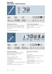
2.1 Quartz discharge tube<br />
The discharge tubes in 1st-generation metal <strong>halide</strong><br />
<strong>lamps</strong> are made of high purity quartz glass. This quartz<br />
material allows <strong>for</strong> stable operation at high temperatures,<br />
is resistant to sudden changes in temperature<br />
<strong>and</strong> is transparent. The well proven HQI <strong>lamps</strong> are produced<br />
in various different <strong>for</strong>ms using this technology.<br />
H ... Hydrargyrum (Greek-Latin <strong>for</strong> mercury)<br />
Q ... Quartz<br />
I ... Iodide<br />
• Well proven lamp technology<br />
• Wide wattage range 70 W – 3500 W<br />
• Colour temperatures up to 7200 K<br />
• Good optical properties thanks to transparent<br />
discharge tube<br />
The <strong>use</strong> of arc tubes made of ceramic material fur<strong>the</strong>r<br />
enhanced some of <strong>the</strong> metal <strong>halide</strong> lamp’s properties.<br />
Ceramic can withst<strong>and</strong> higher temperatures than<br />
quartz glass. This permits higher wall temperatures<br />
<strong>the</strong>reby evaporating more of <strong>the</strong> metal <strong>halide</strong> salts into<br />
<strong>the</strong> gas arc <strong>and</strong> allowing <strong>for</strong> more efficient <strong>use</strong> of <strong>the</strong><br />
chemicals. Ceramic <strong>lamps</strong> offer improved luminous<br />
efficacy <strong>and</strong> colour rendering as a result.<br />
Ceramic arc tubes can be produced with smaller<br />
dimensional tolerances, reducing <strong>the</strong> variation in lighttechnical<br />
<strong>and</strong> electrical parameters.<br />
Ceramic is less susceptible to attacks from <strong>the</strong> aggressive<br />
metal <strong>halide</strong> filling <strong>and</strong> is less permeable <strong>for</strong><br />
filling particles, resulting in a considerably longer<br />
service life compared to quartz tube <strong>lamps</strong>.<br />
Ceramic arc tubes are now available in various different<br />
<strong>for</strong>ms: <strong>the</strong> original cylindrical version <strong>and</strong> <strong>the</strong> improved<br />
round version.<br />
2.2.1 1st generation: cylindrical <strong>for</strong>m<br />
In <strong>the</strong> first version, <strong>the</strong> ceramic arc tube was designed<br />
in a cylindrical <strong>for</strong>m, based on <strong>the</strong> production technology<br />
<strong>for</strong> <strong>the</strong> high-pressure sodium lamp. The arc tube<br />
was made up of cylindrical sub-sections sintered toge<strong>the</strong>r.<br />
The arc tube consisted of a relatively thick plug<br />
at ei<strong>the</strong>r end of <strong>the</strong> tube: this was necessary <strong>for</strong> <strong>the</strong><br />
durability <strong>and</strong> functioning of <strong>the</strong> tube.<br />
2.2.2 2nd generation: freely moldable ceramic,<br />
POWERBALL<br />
A second step with changed production technology<br />
permitted production of freely moldable tube geometries.<br />
This made it possible to produce round ceramic<br />
arc tubes with a constant wall thickness – <strong>the</strong><br />
POWERBALL arc tubes. The round <strong>for</strong>m <strong>and</strong> constant<br />
wall thickness brought considerable advantages. The<br />
possibility of fur<strong>the</strong>r increasing <strong>the</strong> wall temperature<br />
improves luminous efficacy <strong>and</strong> colour rendering. The<br />
absence of <strong>the</strong> thick plug at <strong>the</strong> end of <strong>the</strong> tube reduces<br />
light absorption in this area, resulting in a higher<br />
luminous flux with more uni<strong>for</strong>m irradiation characteristics.<br />
There are fewer differences in <strong>the</strong> wall temperature<br />
between <strong>the</strong> various burning positions <strong>and</strong> <strong>the</strong>re<strong>for</strong>e<br />
also smaller differences in colour between <strong>the</strong><br />
burning positions. The reduced ceramic mass of <strong>the</strong><br />
round tube enables <strong>the</strong> tube to heat up faster, reaching<br />
<strong>the</strong> photometric values more quickly. Similarly, when<br />
<strong>the</strong> lamp goes off, warm re-ignition is possible more<br />
quickly beca<strong>use</strong> <strong>the</strong> required cooler starting temperature<br />
<strong>for</strong> normal ignition devices is achieved faster.<br />
The uni<strong>for</strong>m wall thickness <strong>and</strong> round shape produce a<br />
more even temperature curve along <strong>the</strong> inner tube wall<br />
as shown in Fig. 3, based on <strong>the</strong> temperature shown in<br />
colours diagram. The steeper temperature gradient in<br />
<strong>the</strong> cylindrical ceramic favors chemical transport processes.<br />
During this process, aluminum oxide ceramic<br />
dissolves in <strong>the</strong> liquid metal <strong>halide</strong> melt <strong>and</strong> settles<br />
at cooler points of <strong>the</strong> arc tube. If erosion from <strong>the</strong><br />
wall goes too far, this can lead to leakage in <strong>the</strong> tube,<br />
causing <strong>the</strong> lamp to fail. Failures due to so-called<br />
“ceramic corrosion” are thus less likely to occur in<br />
<strong>lamps</strong> with round ceramic tubes.
Solution of<br />
Alumina<br />
in MH-melt<br />
= Corrosion<br />
Transport of<br />
soluble<br />
alumina in<br />
MH-melt<br />
Deposition of alumina<br />
by saturation of HM-melt<br />
due to cooling<br />
Fig. 3: Comparison of ceramic corrosion between <strong>the</strong> different tube <strong>for</strong>ms<br />
The advantages of POWERBALL technology compared to cylindrical solutions<br />
• Better maintained luminous flux throughout <strong>the</strong> service life<br />
• Improved color rendering, particularly in <strong>the</strong> red<br />
• Improved color stability during <strong>the</strong> service life<br />
• More uni<strong>for</strong>m operation independent of burning position<br />
• More constant luminous intensity distribution<br />
• Faster start-up behavior<br />
9000 h<br />
Convection<br />
Condensation<br />
of <strong>Metal</strong>l Halides<br />
Evaporation<br />
of <strong>Metal</strong> Halides<br />
1100<br />
1060<br />
1020<br />
980<br />
940<br />
12000 h<br />
Convection<br />
Evaporation<br />
of <strong>Metal</strong> Halides<br />
Condensation<br />
of<br />
<strong>Metal</strong> Halides<br />
7
8<br />
3 Ballasts <strong>for</strong> discharge <strong>lamps</strong><br />
Since <strong>the</strong> discharge reacts to increasing lamp current<br />
with falling voltage (which would ca<strong>use</strong> <strong>the</strong> current to<br />
rise indefinitely until <strong>the</strong> f<strong>use</strong> blows or ano<strong>the</strong>r part of<br />
<strong>the</strong> circuit fails), <strong>the</strong> lamp current must be limited by<br />
a ballast during operation. This usually consists of an<br />
inductive circuit (choke), although in rare cases up to<br />
400 W capacitive circuits are also possible (although<br />
this usually results in a shorter service life). In <strong>the</strong><br />
blended lamp (HWL), <strong>the</strong> resistance of <strong>the</strong> filament<br />
serves as a series resistor <strong>for</strong> <strong>the</strong> high-pressure mercury<br />
discharge lamp. In most cases, additionally to <strong>the</strong><br />
current-limiting element, an ignition device is needed<br />
to start discharge (see chapter 4 “Ignition <strong>and</strong> starting<br />
discharge <strong>lamps</strong>”).<br />
In modern luminaires, an electronic ballast fulfils <strong>the</strong><br />
function of igniting <strong>the</strong> lamp, limiting <strong>the</strong> lamp current<br />
<strong>and</strong> controlling <strong>the</strong> lamp wattage.<br />
3.1 Inductive ballasts (chokes)<br />
The voltage across <strong>the</strong> electromagnetic ballast increases<br />
as <strong>the</strong> current increases, <strong>the</strong>re<strong>for</strong>e a stable<br />
working point can be achieved in <strong>the</strong> series connection<br />
of <strong>the</strong> discharge lamp <strong>and</strong> <strong>the</strong> choke.<br />
UNUS K<br />
CPFC<br />
Dr Ch<br />
La<br />
C K … PFC ... Kompensationskondensator<br />
PFC capacitor<br />
La La ... … lamp Lampe<br />
US U... supply voltage<br />
N …Netzspannung<br />
Ch Dr ... … choke Drossel<br />
Fig. 4: Discharge lamp with inductive ballast (ignition<br />
unit has been left out, <strong>the</strong> various possibilities are featured<br />
in chapter 4 “Ignition <strong>and</strong> start-up of discharge<br />
<strong>lamps</strong>”)<br />
Describing <strong>the</strong> relationships of current <strong>and</strong> voltage<br />
requires a system of differential equations which cannot<br />
generally be solved. The following approximation<br />
<strong>for</strong>mulas describe how <strong>the</strong> lamp current <strong>and</strong> lamp<br />
wattage depend on <strong>the</strong> relationship of lamp voltage to<br />
supply voltage [3]:<br />
P<br />
I<br />
US<br />
Z<br />
⎛ n ⎞<br />
⋅ n ⎜1−<br />
⎟<br />
⎝ 3 ⎠<br />
2<br />
2 1/<br />
2<br />
L = [ ( 1−<br />
n ) − 0,<br />
25 n]<br />
2 1/<br />
2<br />
L [ ( 1−<br />
n ) − 0,<br />
25 n]<br />
US<br />
≈<br />
Z<br />
whereby: (1-n/3) ....approximation <strong>for</strong> <strong>the</strong> lamp<br />
power factor λ L<br />
(Gl. 4.1)<br />
(Gl. 4.2)<br />
P L ..... lamp wattage in W<br />
U S ..... supply voltage in V<br />
n ..... ratio of lamp voltage U L to supply voltage U S<br />
Z ..... choke impedance<br />
Charting <strong>the</strong> equations results in <strong>the</strong> curves shown in<br />
Fig. 5. The difference between lamp wattage <strong>and</strong> <strong>the</strong><br />
product of lamp voltage <strong>and</strong> lamp current is called<br />
lamp power factor. It reaches values between 0.7 <strong>and</strong><br />
0.95 depending on <strong>the</strong> operating mode. The yellow<br />
curve was generated by using a higher lamp power<br />
factor λ L (to be more exact: 1.05*(1-n/3)].<br />
Typical voltage <strong>and</strong> current wave<strong>for</strong>ms as shown in<br />
Fig. 6 show that while <strong>the</strong> current is (approximately)<br />
sinusoidal, voltage is not. After <strong>the</strong> current zero crossing,<br />
<strong>the</strong> voltage initially increases (so-called re-ignition<br />
peak) to <strong>the</strong>n fall to a relatively constant value (saddle)<br />
(see also chapter 6.2.2 <strong>and</strong> Fig. 30). Voltage remains<br />
approximately <strong>the</strong> same beyond <strong>the</strong> maximum of <strong>the</strong><br />
current, <strong>and</strong> has <strong>the</strong> same zero crossing as <strong>the</strong> current.<br />
So <strong>the</strong>re are areas with high voltage which count<br />
towards <strong>the</strong> effective value of <strong>the</strong> voltage but don’t<br />
contribute to <strong>the</strong> wattage as <strong>the</strong> current at that point in<br />
time is nearly zero. This results in lamp power factors<br />
deviating from <strong>the</strong> value 1.<br />
If <strong>the</strong> lamp voltage is equal to zero, <strong>the</strong> voltage drop<br />
across <strong>the</strong> choke is <strong>the</strong> entire supply voltage, <strong>and</strong> <strong>the</strong><br />
choke short-circuit current is reached. This is <strong>the</strong> maximum<br />
current that can flow through <strong>the</strong> choke inasmuch<br />
<strong>the</strong> current has no DC component (see chapter<br />
6.2.9 <strong>for</strong> effects of direct current components).<br />
The following curves are typical <strong>for</strong> 150 W <strong>and</strong> apply in<br />
<strong>the</strong> same way to o<strong>the</strong>r wattages.<br />
Lamp power P L in W<br />
180<br />
160<br />
140<br />
120<br />
100<br />
80<br />
60<br />
40<br />
20<br />
P L<br />
I L<br />
5 % higher lamp<br />
power factor<br />
0<br />
0 0,5<br />
U L/US 0<br />
1<br />
Fig. 5: Lamp current I L, lamp wattage P L over <strong>the</strong> ratio<br />
of lamp voltage to supply voltage U L/U S; Z=99 Ω <strong>for</strong> a<br />
150 W lamp<br />
Voltage in V Current in A<br />
Time in ms<br />
Fig. 6: Graph showing lamp voltage <strong>and</strong> current of a<br />
150 W lamp when operated at a choke (applies in <strong>the</strong><br />
same way to o<strong>the</strong>r wattages)<br />
2,5<br />
2<br />
1,5<br />
1<br />
0,5<br />
Lamp current I L in A
This lamp behavior results from <strong>the</strong> relatively flat zero<br />
crossing <strong>for</strong> sinusoidal current. When <strong>the</strong> current approaches<br />
zero, <strong>the</strong> plasma temperature decreases <strong>and</strong><br />
<strong>the</strong> electrodes also cool down. The recombination of<br />
electrons with ions reduces conductivity. After <strong>the</strong> zero<br />
crossing, <strong>the</strong> conductivity is too low to take up <strong>the</strong><br />
current that <strong>the</strong> choke wants to drive. As a result, <strong>the</strong><br />
voltage through <strong>the</strong> lamp increases again significantly<br />
until <strong>the</strong> lamp “reignites”. The higher voltage results<br />
in a higher ionization rate that increases conductivity<br />
again so that voltage falls.<br />
By contrast, current <strong>and</strong> voltage <strong>for</strong> <strong>the</strong> rectangular<br />
wave<strong>for</strong>ms of an electronic ballast change significantly<br />
faster from positive to negative half-wave, or<br />
have a faster commutation times (see chapter 3.2<br />
“Electrical ballasts (ECG)”), so that <strong>the</strong> plasma has<br />
little chance to cool down. The instantaneous voltage<br />
required from <strong>the</strong> electronic ballast is <strong>the</strong>re<strong>for</strong>e significantly<br />
lower than <strong>for</strong> <strong>the</strong> choke. This is one of <strong>the</strong><br />
advantages of electronic ballast, as one of <strong>the</strong> failure<br />
mechanisms of metal <strong>halide</strong> <strong>lamps</strong> is to extinguish<br />
due to high re-ignition voltage. The re-ignition peak<br />
of a lamp normally increases over <strong>the</strong> service life, <strong>and</strong><br />
when it exceeds what <strong>the</strong> supply voltage momentarily<br />
can provide, <strong>the</strong>re is no “re-ignition” <strong>and</strong> <strong>the</strong> lamp<br />
goes out (see also chapter 6.2.2 “Increase of <strong>the</strong><br />
re-ignition peak”).<br />
When operating on a conventional choke, <strong>the</strong> lamp<br />
wattage runs through a maximum depending on <strong>the</strong><br />
lamp voltage (see Fig. 5). The maximum occurs <strong>for</strong> a<br />
lamp voltage of slightly more than half <strong>the</strong> supply voltage.<br />
Near <strong>the</strong> maximum <strong>the</strong> lamp wattage changes<br />
only slightly with <strong>the</strong> lamp voltage. During <strong>the</strong> lamp<br />
service life, <strong>the</strong> lamp voltage increases, as also shown<br />
in chapter 6 “Lamp lifecycle, aging <strong>and</strong> failure behavior”.<br />
In order <strong>for</strong> <strong>the</strong> lamp wattage to change as little<br />
as possible, <strong>the</strong> nominal value <strong>for</strong> lamp voltage is generally<br />
chosen near <strong>the</strong> maximum, <strong>the</strong>re<strong>for</strong>e at about<br />
half <strong>the</strong> supply voltage.<br />
The impedance of <strong>the</strong> choke is rated at a certain supply<br />
frequency <strong>and</strong> certain supply voltage. Deviations<br />
from <strong>the</strong> nominal supply voltage will result in a different<br />
ballast curve <strong>and</strong> a related different working point<br />
<strong>for</strong> <strong>the</strong> lamp <strong>and</strong> <strong>the</strong>re<strong>for</strong>e different lamp wattage. To<br />
limit <strong>the</strong> associated greater spread in <strong>the</strong> lamp parameters,<br />
a maximum deviation of 5% from <strong>the</strong> nominal<br />
values is permitted in <strong>the</strong> short term <strong>for</strong> <strong>the</strong> supply<br />
voltage, or maximum 3% in <strong>the</strong> long term. For deviations<br />
over a longer period of time, suitable choke tap<br />
must be selected. Similarly, <strong>the</strong> choke impedance<br />
must not deviate from <strong>the</strong> nominal values by more than<br />
2% (see also chapter 3.1.3 “Influence of deviations in<br />
supply voltage”).<br />
• Maximum permitted supply voltage deviations:<br />
5% in <strong>the</strong> short-term, 3% in <strong>the</strong> long-term, <strong>use</strong><br />
o<strong>the</strong>r tap on <strong>the</strong> choke if necessary.<br />
• Maximum deviation of choke impedance 2%.<br />
As per <strong>the</strong> IEC 61167 st<strong>and</strong>ard, ballast units <strong>for</strong> MH<br />
<strong>lamps</strong> must by protected from overheating through<br />
rectification. This can be done e.g. with a <strong>the</strong>rmal f<strong>use</strong><br />
(tested according to IEC 598-1, Annex C).<br />
3.1.1 American circuits <strong>for</strong> ballasts<br />
In this context it is important to note that <strong>the</strong> supply<br />
voltage in America has a different frequency (60 Hz).<br />
As <strong>the</strong> inductive resistance of <strong>the</strong> choke depends<br />
on <strong>the</strong> frequency, in this case it is important to <strong>use</strong> a<br />
designated ballast <strong>for</strong> <strong>the</strong> corresponding frequency. In<br />
addition, both <strong>lamps</strong> <strong>and</strong> ballasts in <strong>the</strong> USA are st<strong>and</strong>ardized<br />
by ANSI, <strong>the</strong> American National St<strong>and</strong>ards<br />
Institute. To operate <strong>the</strong> systems correctly, <strong>lamps</strong> must<br />
be operated with corresponding ballasts. Ratings designations<br />
are required by ANSI to be marked clearly on<br />
all products, allowing <strong>use</strong>rs to clearly identify system<br />
agreement.<br />
3.1.1.1 Autoleak trans<strong>for</strong>mer or high reactance autotrans<strong>for</strong>mer<br />
If <strong>the</strong> supply voltage is smaller than around twice <strong>the</strong><br />
lamp voltage, as is <strong>the</strong> case, <strong>for</strong> example, in <strong>the</strong> USA<br />
or Japan, <strong>the</strong>n <strong>the</strong> supply voltage must first be stepped<br />
up. A good way of doing this is <strong>use</strong> an autoleak trans<strong>for</strong>mer.<br />
Part of <strong>the</strong> secondary windings act as lamp<br />
choke. On <strong>the</strong> one h<strong>and</strong>, this saves on material, <strong>and</strong> on<br />
<strong>the</strong> o<strong>the</strong>r h<strong>and</strong>, a higher voltage (open-circuit voltage)<br />
is available to start <strong>the</strong> lamp. These types of ballasts<br />
are typically more economical than a constant wattage<br />
style ballasts at <strong>the</strong> expense of wattage regulation.<br />
US C PFC<br />
Fig. 7: Autoleak trans<strong>for</strong>mer<br />
3.1.1.2 Constant wattage ballast<br />
A constant wattage ballast such as those widely available<br />
in <strong>the</strong> USA consists of an autoleak trans<strong>for</strong>mer in<br />
series with a capacitor. The advantage of this circuit is<br />
<strong>the</strong> reduced impact of fluctuations in <strong>the</strong> supply voltage<br />
<strong>and</strong> <strong>the</strong> possibility of operating <strong>the</strong> lamp at supply<br />
voltages (110/120 V in <strong>the</strong> USA, 100 V in Japan) that<br />
lie within <strong>the</strong> range of <strong>the</strong> lamp voltage.<br />
• The choke must be protected against overheating<br />
according to <strong>the</strong> st<strong>and</strong>ard (<strong>the</strong>rmal f<strong>use</strong>). Fig. 8: Constant wattage ballast<br />
US<br />
Tr<br />
Tr<br />
C<br />
La<br />
La<br />
C PFC ... PFC capacitor<br />
La ... lamp<br />
U S ... supply voltage<br />
Tr ... autoleak trans<strong>for</strong>mer<br />
C ... capacitor<br />
La ... lamp<br />
U S ... supply voltage<br />
Tr ... autoleak trans<strong>for</strong>mer<br />
9
10<br />
3.1.2 Variation in supply voltage <strong>for</strong> adapted<br />
inductance<br />
Some countries have supply voltages that permanently<br />
deviate from 230V. When using correspondingly adapted<br />
inductances, <strong>the</strong> following points must be taken<br />
into account.<br />
3.1.2.1 Operation at supply voltage higher than 230 V<br />
with adapted choke impedance<br />
An increase in supply voltage shifts <strong>the</strong> maximum of<br />
<strong>the</strong> choke characteristic curve (P L over U L/U N). In <strong>the</strong><br />
lamp voltage range of OSRAM <strong>lamps</strong> (approx. 100 V),<br />
<strong>the</strong> change in lamp wattage with changing lamp voltage<br />
is steeper. In addition, <strong>the</strong> maximum wattage that<br />
can be achieved with increasing lamp voltage is larger,<br />
as shown in Fig. 9. Normally, <strong>the</strong> lamp voltage increases<br />
with increasing service life (see also chapter 6<br />
“Lamp service life, aging <strong>and</strong> failure behavior”).<br />
According to equation Eq. 4.1, wattage of about 150 W<br />
is achieved <strong>for</strong> a 150 W choke with a lamp voltage of<br />
100 V. The maximum <strong>the</strong> lamp wattage can increase<br />
to <strong>for</strong> a lamp voltage of 150 V is 175 W. The higher<br />
achievable wattage can reduce <strong>the</strong> service life <strong>and</strong><br />
possibly ca<strong>use</strong> an increase of undesirable effects at<br />
<strong>the</strong> end of <strong>the</strong> service life (e.g. lamp explosion).<br />
OSRAM <strong>lamps</strong> are generally designed to operate at<br />
230 V supply voltage <strong>and</strong> undergo corresponding service<br />
life testing. There are, however, also systems at<br />
400 V, e.g. <strong>for</strong> some discharge <strong>lamps</strong> > 1000 W. For<br />
<strong>the</strong>se <strong>lamps</strong>, <strong>the</strong> following explanations apply in <strong>the</strong><br />
same way. The <strong>use</strong> of high intensity discharge <strong>lamps</strong> is<br />
<strong>the</strong>oretically also possible at 277 V operating voltage<br />
with adapted impedance <strong>and</strong> ignition devices, although<br />
such operation is associated with considerable disadvantages.<br />
a) An increase in negative effects must be expected<br />
at <strong>the</strong> end of <strong>the</strong> service life, beca<strong>use</strong> wattage<br />
rises clearly above <strong>the</strong> nominal wattage when<br />
lamp voltage increases on account of <strong>the</strong> shifted<br />
choke characteristic curve. The increased wattage<br />
input <strong>for</strong> <strong>lamps</strong> with already aged arc tube<br />
wall can ca<strong>use</strong> increased lamp explosion rates,<br />
<strong>for</strong> example. Operation in overload conditions<br />
will probably ca<strong>use</strong> accelerated aging.<br />
b) The steeper characteristic P L(U L) in <strong>the</strong> range of<br />
<strong>the</strong> normal lamp voltage ca<strong>use</strong>s a higher spread<br />
of <strong>the</strong> wattage <strong>and</strong> <strong>the</strong>re<strong>for</strong>e of <strong>the</strong> photometric<br />
data, e.g. perceived colour variation.<br />
We <strong>the</strong>re<strong>for</strong>e discourage operating <strong>the</strong> <strong>lamps</strong> at 277 V<br />
supply voltage. Our <strong>lamps</strong> have been developed <strong>and</strong><br />
undergone service life testing at 230 V supply voltage,<br />
so that we cannot assume any warranty <strong>for</strong> <strong>the</strong> service<br />
life behavior <strong>and</strong> photometric data <strong>for</strong> any deviating<br />
operation.<br />
Lamp power P L in W<br />
200<br />
180<br />
160<br />
140<br />
120<br />
100<br />
80<br />
60<br />
40<br />
20<br />
0<br />
0 0,5<br />
U L/US 0<br />
1<br />
Fig. 9: Lamp current I L, lamp wattage P L over <strong>the</strong> ratio<br />
of lamp voltage to supply voltage U L/U S <strong>for</strong> U S=277 V<br />
3.1.2.2 Operation at supply voltage less than 230 V<br />
with adapted choke impedance<br />
Supply voltages of less than 230 V shift <strong>the</strong> maximum<br />
of <strong>the</strong> choke curve (P L over U L/U S). Operation at 200 V<br />
supply voltage <strong>for</strong> example is more favorable than at<br />
230 V with regard to <strong>the</strong> change in lamp wattage with<br />
lamp voltage. The P L(U L) curve runs flatter in <strong>the</strong> normal<br />
range of lamp voltage. For lamp voltages exceeding<br />
130 V Wattage falls again.<br />
Lamp power P L in W<br />
200<br />
180<br />
160<br />
140<br />
120<br />
100<br />
80<br />
60<br />
40<br />
20<br />
0<br />
0 0,5<br />
U L/US 0<br />
1<br />
Fig. 10: Lamp current I L, lamp wattage P L over <strong>the</strong> ratio<br />
of lamp voltage to supply voltage U L/U S at U N=200 V<br />
There is a major drawback that with lower supply voltage,<br />
<strong>the</strong>re is also less voltage available <strong>for</strong> re-ignition<br />
after <strong>the</strong> current has passed zero crossing. If <strong>the</strong> momentary<br />
supply voltage is lower than <strong>the</strong> re-ignition<br />
voltage, <strong>the</strong> lamp goes off. Normally, <strong>the</strong> lamp voltage<br />
<strong>and</strong> also <strong>the</strong> re-ignition peak increase with increasing<br />
service life (see also chapter 6, “Lamp service life, aging<br />
<strong>and</strong> failure behavior”). That means that a reduction<br />
in supply voltage ca<strong>use</strong>s a shorter service life in many<br />
<strong>lamps</strong>.<br />
3<br />
2,5<br />
2<br />
1,5<br />
1<br />
0,5<br />
3<br />
2,5<br />
2<br />
1,5<br />
1<br />
0,5<br />
Lamp current I L in A<br />
Lamp current I in A<br />
L
3.1.3 Influence of deviations in supply voltage<br />
When operating metal <strong>halide</strong> <strong>lamps</strong> on a choke, <strong>the</strong><br />
lamp parameters change depending on <strong>the</strong> supply<br />
voltage. To limit <strong>the</strong> associated variation in lamp photometrics,<br />
a maximum deviation in supply voltage of<br />
5% from <strong>the</strong> nominal values <strong>for</strong> <strong>the</strong> supply voltage is<br />
permitted in <strong>the</strong> short term, or maximum 3% in <strong>the</strong><br />
long term. For deviations over a longer period of time,<br />
suitable ballast tap must be selected. As choke impedance<br />
also influences <strong>the</strong> lamp parameters via <strong>the</strong> correspondingly<br />
adjusted lamp current, this is allowed to<br />
deviate from <strong>the</strong> nominal values by maximum 2%.<br />
Remote mounting can also ca<strong>use</strong> noticeable decreases<br />
in voltage (see also chapter 7.4 “Leads to<br />
luminaires”).<br />
Long term reductions in lamp wattage ca<strong>use</strong> <strong>the</strong> luminous<br />
flux to decrease, with a shorter service life <strong>and</strong><br />
a deviation in colour from <strong>the</strong> nominal values, as also<br />
explained in chapter 5: “Wattage reduction in high<br />
intensity discharge <strong>lamps</strong>”.<br />
If <strong>the</strong> supply voltage is too high, <strong>the</strong> arc tube is operated<br />
at too hot a temperature, causing increased<br />
blackening <strong>and</strong> a shorter service life.<br />
Percentage of <strong>the</strong> nominal value<br />
UL in %<br />
IL in %<br />
PL in %<br />
FL in %<br />
Percentage of <strong>the</strong> nominal supply voltage<br />
UL ... Lamp voltage<br />
IL ... Lamp current<br />
PL ... Lamp power<br />
FL ... Luminous flux<br />
Fig. 11: Lamp parameters of a typical OSRAM HQI<br />
lamp over supply voltage<br />
Percentage of <strong>the</strong> nominal value<br />
UL in %<br />
IL in %<br />
PL in %<br />
FL in %<br />
Percentage of <strong>the</strong> nominal supply voltage<br />
UL ... Lamp voltage<br />
IL ... Lamp current<br />
PL ... Lamp power<br />
FL ... Luminous flux<br />
Fig. 12: Lamp parameters of a typical OSRAM HCI<br />
lamp over supply voltage<br />
3.1.4 Capacitor <strong>for</strong> power factor correction<br />
The capacitor <strong>for</strong> power factor correction is necessary<br />
to correct <strong>the</strong> power factor of <strong>the</strong> system when<br />
operating discharge <strong>lamps</strong> at electromagnetic ballasts.<br />
Inductively stabilized discharge <strong>lamps</strong> achieve power<br />
factors of only about 0.5 beca<strong>use</strong> of <strong>the</strong> dephased<br />
current flow. The power factor of a load is defined<br />
as <strong>the</strong> ratio of effective power to <strong>the</strong> apparent power<br />
actually withdrawn from <strong>the</strong> grid (kW to kvar) <strong>and</strong> is<br />
referred to as cos ϕ. The closer cos ϕ is to one, <strong>the</strong><br />
smaller is <strong>the</strong> share of wattless power withdrawn from<br />
<strong>the</strong> grid. A higher share of wattless power results in a<br />
higher flow in current <strong>for</strong> which <strong>the</strong> supply lines have<br />
to be rated. Similarly, power dissipation in <strong>the</strong> supply<br />
lines increases in a square progression with <strong>the</strong><br />
current. In order to achieve <strong>the</strong> values dem<strong>and</strong>ed by<br />
<strong>the</strong> utility companies of more than 0.85, a grid parallel<br />
capacitor must be selected according to <strong>the</strong> lamp<br />
or choke current to approximately correct <strong>the</strong> shift<br />
in phase. By including an exactly calculated capacitor,<br />
<strong>the</strong> inductive wattless load required by an electric<br />
consumer can be offset with a capacitive wattless<br />
load. It is thus possible to reduce <strong>the</strong> wattless power<br />
withdrawn from <strong>the</strong> grid; this is called <strong>the</strong> power factor<br />
correction or wattless power compensation.<br />
The capacitors are differentiated as follows,<br />
depending on <strong>the</strong> arrangement <strong>and</strong> <strong>for</strong>m of <strong>use</strong>:<br />
INDIVIDUAL OR FIXED COMPENSATION, where <strong>the</strong><br />
inductive wattless power is corrected directly where<br />
it occurs, relieving <strong>the</strong> strain on <strong>the</strong> leads (typical <strong>for</strong><br />
individual consumers usually working in continuous<br />
mode with constant or relatively large wattage – discharge<br />
<strong>lamps</strong>, asynchronous motors, trans<strong>for</strong>mers,<br />
welding equipment, etc.)<br />
11
12<br />
The parallel capacitor has no influence on lamp<br />
behavior.<br />
GROUP COMPENSATION, where one joint fixed capacitor<br />
is allocated to simultaneously working inductive<br />
consumers, similar to individual correction (motors<br />
located close toge<strong>the</strong>r, discharge <strong>lamps</strong>). Here again<br />
<strong>the</strong> strain on <strong>the</strong> leads is relieved, but only up to <strong>the</strong><br />
point of distribution to <strong>the</strong> individual consumers. Under<br />
unfavorable conditions, resonance can be ca<strong>use</strong>d<br />
in two-phase grids.<br />
CENTRAL COMPENSATION, where a number of capacitors<br />
are connected to a main or sub-distribution<br />
station. This is <strong>the</strong> normal procedure in large electrical<br />
systems with changing load. Here <strong>the</strong> capacitors are<br />
controlled by an electronic controller which constantly<br />
analyzes <strong>the</strong> dem<strong>and</strong> <strong>for</strong> wattless power in <strong>the</strong> grid.<br />
This controller switches <strong>the</strong> capacitors on or off to correct<br />
<strong>the</strong> current wattless power of <strong>the</strong> total load <strong>and</strong><br />
thus reduce overall dem<strong>and</strong> in <strong>the</strong> grid.<br />
Capacitor <strong>for</strong> power factor correction values are<br />
stated <strong>for</strong> every lamp type in <strong>the</strong> Technical In<strong>for</strong>mation<br />
<strong>and</strong> can also be calculated using <strong>the</strong> following equation.<br />
1 2<br />
⎛ 2 2<br />
C ( )⎟<br />
⎞<br />
PFC = × ⎜ US<br />
× IL<br />
− PW<br />
− PW<br />
× tanϕ<br />
2<br />
K Eq. 4.3<br />
2 × π × f × U ⎝<br />
⎠<br />
S<br />
S<br />
C PFC in F Capacitance of <strong>the</strong> capacitor <strong>for</strong> power<br />
factor correction<br />
U S in V Rated supply voltage<br />
f S in Hz Supply frequency<br />
I L in A Lamp rated current<br />
P W in W Total active power (lamp rated wattage plus<br />
choke loss wattage)<br />
ϕ K Tolerable or desirable phase difference between<br />
<strong>the</strong> fundamental waves of <strong>the</strong> supply<br />
voltage <strong>and</strong> <strong>the</strong> supply current.<br />
But this only corrects <strong>the</strong> power factor <strong>for</strong> <strong>the</strong> fundamental<br />
wave. Phase difference remains <strong>for</strong> distortion,<br />
i.e. <strong>the</strong> harmonic waves, between current <strong>and</strong> voltage.<br />
For this reason, <strong>the</strong> overall power factor can also only<br />
reach values between 0.95 <strong>and</strong> 0.98 in practice.<br />
A higher level of harmonic waves can ca<strong>use</strong> resonance<br />
effects <strong>and</strong> destroy <strong>the</strong> lamp. A power factor close to 1<br />
is to be avoided as this can ca<strong>use</strong> resonance between<br />
<strong>the</strong> choke <strong>and</strong> correction capacitor.<br />
While a discharge lamp is starting up, <strong>the</strong> power factor<br />
undergoes significant changes in value. After ignition,<br />
<strong>the</strong> lamp voltage is still very low with current higher<br />
than in steady state. This is why <strong>the</strong> power factor in<br />
this state is still low (inductive). While lamp voltage<br />
increases <strong>and</strong> <strong>the</strong> lamp current falls, <strong>the</strong> power factor<br />
increases to its nominal value of 0.85 – 0.9.<br />
As discharge <strong>lamps</strong> age, it is normal <strong>for</strong> lamp voltage<br />
to increase, causing <strong>the</strong> lamp current to fall according<br />
to <strong>the</strong> ballast curve. Beca<strong>use</strong> <strong>the</strong> capacitor <strong>for</strong> power<br />
factor correction is rated <strong>for</strong> a specific lamp <strong>and</strong> choke<br />
current, <strong>the</strong> power factor varies according to lamp<br />
current. For an extremely high lamp voltage, <strong>the</strong> choke<br />
current is so low that capacitive current exceeds <strong>the</strong><br />
inductive current <strong>and</strong> <strong>the</strong> complete circuit becomes<br />
capacitive.<br />
Under certain conditions, audio frequency central control<br />
systems have to be considered during installation.<br />
In <strong>the</strong>se cases, suitable audio frequency attenuation<br />
chokes are to be provided. This kind of system is still<br />
sometimes <strong>use</strong>d <strong>for</strong> day/night circuits in street lighting,<br />
although directional radio systems are finding increasing<br />
<strong>use</strong> here.<br />
3.2 Electronic control gear (ECG)<br />
Toge<strong>the</strong>r with conventional ballasts, <strong>the</strong> <strong>use</strong> of electronic<br />
ballasts has meanwhile become widely accepted<br />
practice, particularly <strong>for</strong> interior lighting.<br />
Electronic ballasts offer clear advantages compared<br />
to conventional ballasts. The main advantages include<br />
in particular simplified h<strong>and</strong>ling (e.g. lighter ballasts),<br />
lower energy consumption, a positive impact on lamp<br />
service life <strong>and</strong> light quality, <strong>and</strong>, last but not least,<br />
controlled <strong>and</strong> reliable shutdown of <strong>lamps</strong> at <strong>the</strong> end<br />
of <strong>the</strong> service life.<br />
Basically, most of <strong>the</strong> technical in<strong>for</strong>mation provided in<br />
this manual applies to both conventional ballasts <strong>and</strong><br />
electronic ballasts. This refers <strong>for</strong> example to wiring<br />
requirements, wattage-reduced operation of MH <strong>lamps</strong><br />
or instructions <strong>for</strong> luminaire design.<br />
But in addition, <strong>the</strong>re are also considerable differences<br />
between operation on an electronic or magnetic ballast.<br />
The following section briefly explains <strong>the</strong> main differences<br />
<strong>and</strong> <strong>the</strong>ir effects.<br />
3.2.1 Structure <strong>and</strong> functioning of an electronic<br />
ballast<br />
Electronic ballasts mainly consist of units with rectangular<br />
current <strong>and</strong> voltage. In principle, it is also<br />
possible to operate <strong>the</strong> <strong>lamps</strong> with high-frequency<br />
sinusoidal current similar to <strong>the</strong> fluorescent lamp. In<br />
any case, it is important to ensure that no acoustic<br />
resonances occur as <strong>the</strong>se may result in arc instability<br />
(lamp flicker) <strong>and</strong> in severe cases, lamp rupture.
ECG<br />
U S<br />
Luminaire<br />
Lamp<br />
Fig. 13: Simplified circuit diagram showing <strong>the</strong> electronic<br />
operation of high intensity discharge <strong>lamps</strong><br />
Voltage in V Current in A<br />
Time in ms<br />
Fig. 14: Current <strong>and</strong> voltage of a metal <strong>halide</strong> lamp<br />
operated on a rectangular electronic ballast<br />
3.2.2 Service life <strong>and</strong> temperature<br />
There is a significant difference between conventional<br />
<strong>and</strong> electronic ballasts particularly with regard to <strong>the</strong><br />
service life <strong>and</strong> <strong>the</strong>rmal behavior of <strong>the</strong> units.<br />
For a conventional ballast, it can be presumed that <strong>the</strong><br />
service life is defined by <strong>the</strong> choke temperature t w. A<br />
10 °C increase in <strong>the</strong> t w temperature means that <strong>the</strong><br />
service life is halved.<br />
In electronic ballasts, <strong>the</strong>se circumstances are far<br />
more complicated. The mortality rate of individual<br />
components, <strong>the</strong> circuit design <strong>and</strong> above all <strong>the</strong> electronic<br />
load <strong>and</strong> <strong>the</strong> temperatures at which <strong>the</strong> units are<br />
operated have a considerable influence on <strong>the</strong> service<br />
life behavior.<br />
This is why <strong>the</strong> nominal service life of electronic ballasts<br />
is stated in combination with a failure probability.<br />
For example, all units in <strong>the</strong> product family POWER-<br />
TRONIC PTi have a nominal service life of 40,000 hours<br />
with failure probability of maximum 10% when operated<br />
at <strong>the</strong> maximum permissible temperatures.<br />
The service life of electronic ballasts is influenced<br />
directly by <strong>the</strong> temperature at which <strong>the</strong> units are operated.<br />
This is why 2 temperature values are defined<br />
to describe <strong>the</strong> <strong>the</strong>rmal behavior. The ambient temperature<br />
t a describes <strong>the</strong> temperature immediately<br />
surrounding <strong>the</strong> unit <strong>and</strong> thus prevailing around <strong>the</strong><br />
electronic components. To be clear, this is not <strong>the</strong><br />
room temperature or <strong>the</strong> ambient temperature of <strong>the</strong><br />
luminaire.<br />
When an electronic ballast is fitted in a luminaire, <strong>the</strong><br />
real ambient temperature t a of <strong>the</strong> ballast can only be<br />
measured with great difficulty <strong>and</strong> at great ef<strong>for</strong>t. This<br />
is why a second temperature has been stipulated: <strong>the</strong><br />
t c temperature. Basically this is <strong>the</strong> casing temperature<br />
which can be measured by a <strong>the</strong>rmocouple at a<br />
set point – <strong>the</strong> t c point – <strong>and</strong> is defined as maximum<br />
permissible temperature at which safe operation of <strong>the</strong><br />
electronic ballast is still guaranteed. In addition, <strong>the</strong> t c<br />
temperature is set in relation to <strong>the</strong> ballast service life.<br />
That means that <strong>the</strong> measured t c temperature permits<br />
very precise conclusions as to <strong>the</strong> anticipated service<br />
life of <strong>the</strong> electronic ballast.<br />
OSRAM’s HID electronic ballast <strong>for</strong> example principally<br />
reaches its full nominal service life at <strong>the</strong> maximum<br />
permitted t c temperature. In practice, this means<br />
that any temperature levels below <strong>the</strong> t c temperature<br />
always prolong <strong>the</strong> effective service life. As a rule of<br />
thumb, it can be presumed that a temperature 10 °C<br />
below <strong>the</strong> printed maximum t c temperature will double<br />
<strong>the</strong> service life of <strong>the</strong> electronic ballast.<br />
However, it is not advisable to <strong>use</strong> only <strong>the</strong> absolute<br />
maximum tolerable t c value <strong>for</strong> conclusions regarding<br />
<strong>the</strong> quality <strong>and</strong> service life of an electronic ballast. This<br />
is beca<strong>use</strong> on <strong>the</strong> one h<strong>and</strong>, <strong>the</strong> position <strong>and</strong> <strong>the</strong>re<strong>for</strong>e<br />
indirectly also <strong>the</strong> value of <strong>the</strong> t c point can be freely<br />
defined by every electronic ballast manufacturer. On<br />
<strong>the</strong> o<strong>the</strong>r h<strong>and</strong>, <strong>the</strong> rule of stating <strong>the</strong> nominal service<br />
life at <strong>the</strong> maximum permitted t c temperature has not<br />
yet become established throughout <strong>the</strong> electronic<br />
ballast industry. In practice this means that many<br />
electronic ballasts only achieve approx. 50% of <strong>the</strong>ir<br />
nominal service life at maximum t c temperature.<br />
Nominal service life (B10): max. 10% of <strong>the</strong><br />
electronic ballasts have failed<br />
A serious evaluation of <strong>the</strong> electronic ballast<br />
service life is only possible by comparing <strong>the</strong><br />
electronic ballast ambient temperature ta with<br />
<strong>the</strong> corresponding service life.<br />
Comparison of <strong>the</strong> service life using only <strong>the</strong> tc<br />
temperature is not appropriate.<br />
3.2.3 Advantages of operation with electronic<br />
ballast POWERTRONIC PTi<br />
The following table provides an overview of <strong>the</strong> advantages<br />
of operating <strong>lamps</strong> with <strong>the</strong> electronic ballast.<br />
The corresponding values <strong>and</strong> statements are based<br />
on tests <strong>and</strong> experience with POWERTRONIC PTi ballasts,<br />
so that <strong>the</strong>y cannot necessarily be transferred<br />
1:1 to ballasts of o<strong>the</strong>r makes.<br />
In comparing <strong>the</strong> conventional <strong>and</strong> <strong>the</strong> electronic<br />
ballast, <strong>the</strong> per<strong>for</strong>mance of <strong>the</strong> conventional ballast<br />
constitutes <strong>the</strong> reference parameter <strong>and</strong> is given a<br />
value of 100. This is also based on <strong>the</strong> fact that <strong>the</strong><br />
lamp parameters are defined with <strong>the</strong> reference<br />
conventional ballast.<br />
13
14<br />
The main advantages of electronic ballasts are<br />
described in greater detail in <strong>the</strong> following section.<br />
3.2.3.1 Reducing energy consumption<br />
Compared to conventional ballasts, electronic ballasts<br />
can considerably reduce energy consumption over <strong>the</strong><br />
service life. The energy savings result from two factors:<br />
1) Unit power dissipation:<br />
In conventional ballasts a large amount of energy<br />
is lost in dissipated heat on account of <strong>the</strong><br />
design. By contrast, electronic ballasts have a<br />
low-loss design with top quality components,<br />
reducing dissipation to less than 10% of <strong>the</strong><br />
nominal power.<br />
2) Increase in wattage over service life:<br />
The system wattage with conventional ballasts<br />
fluctuates significantly over <strong>the</strong> service life of <strong>the</strong><br />
lamp. This results from <strong>the</strong> change in lamp voltage,<br />
which can increase by up to 30% throughout<br />
<strong>the</strong> service life (see also chapter 3.1.2), resulting<br />
in considerable fluctuations in lamp wattage.<br />
Magnetic ballast Electronic ballast POWERTRONIC<br />
Energy consumption 100 10 to 15% savings over <strong>the</strong> service<br />
life<br />
Lamp service life 100 Up to 30% longer depending on<br />
lamp type <strong>and</strong> kind of <strong>use</strong><br />
Lamp start-up Depends on type: usually approx.<br />
60 to 90 sec. to reach 90% of <strong>the</strong><br />
luminous flux level<br />
Up to 50% faster<br />
Colour stability Colour variation possible Clearly reduced scattering; initial <strong>and</strong><br />
over service life<br />
Cut-out at end of lamp service<br />
life<br />
Not available or only simple<br />
cut-out mechanisms<br />
Permanent parameter control,<br />
intelligent cut-out mechanisms<br />
Ignition cut-out Only with timer ignition units Ignition time limited to 18 min<br />
Light flicker Visible flicker Flicker-free thanks to 165 Hz operation<br />
Consistent wattage Increase in wattage over service<br />
life, also dependent on fluctuations<br />
in temperature <strong>and</strong> supply<br />
voltage, <strong>and</strong> on lead length<br />
H<strong>and</strong>ling 3 components, complicated<br />
wiring<br />
Size <strong>and</strong> weight Heavy, several components, large<br />
in some cases<br />
Power factor correction (PFC) 0.5 – 0.95, considerable aging<br />
fluctuations<br />
+ 3% over <strong>the</strong> entire service life,<br />
regardless of fluctuations in<br />
temperature <strong>and</strong> supply voltage<br />
or lead length<br />
1 unit, simple wiring<br />
Light <strong>and</strong> compact<br />
> 0.95<br />
Noise development Clearly audible humming possible Almost noiseless<br />
Bidirectional data exchange Not possible Generally possible<br />
By contrast, electronic ballasts operate <strong>the</strong><br />
<strong>lamps</strong> always with constant wattage throughout<br />
<strong>the</strong> entire service life. The maximal tolerated<br />
fluctuation is 3%. This means <strong>for</strong> example that<br />
<strong>for</strong> a 70 W ceramic arc tube lamp, <strong>the</strong> electronic<br />
ballast constantly provides <strong>the</strong> lamp with <strong>the</strong><br />
rated 73 W.<br />
3.2.3.1 Lamp service life <strong>and</strong> cut-out at <strong>the</strong> end of <strong>the</strong><br />
service life<br />
A detailed description of <strong>the</strong> lamp service life <strong>and</strong> failure<br />
behavior using conventional ballasts can be found<br />
in chapter 6.<br />
Electronic ballast operation also offers considerable<br />
advantages in terms of lamp service life <strong>and</strong> cut-out<br />
behavior at <strong>the</strong> end of <strong>the</strong> service life.<br />
Comprehensive laboratory tests <strong>and</strong> extensive practical<br />
experience show that operation on electronic ballasts<br />
has a significantly positive influence on <strong>the</strong> lamp<br />
service life. Precise but gentle lamp ignition, a more<br />
stable <strong>the</strong>rmal balance thanks to constant wattage
supply <strong>and</strong>, above all, a clearly reduced tendency to<br />
go out by avoiding re-ignition peaks all leng<strong>the</strong>n <strong>the</strong><br />
lamp economic life <strong>for</strong> ceramic arc tube <strong>lamps</strong> by up<br />
to 30% on average.<br />
The electronic ballast also shows its strengths at <strong>the</strong><br />
end of <strong>the</strong> lamp service life. The ignition time limit<br />
ensures that old <strong>lamps</strong>, where stable operation is no<br />
longer possible, are not subject to endless ignition<br />
attempts. After max. 18 minutes <strong>and</strong> precisely defined<br />
ignition intervals, <strong>the</strong> POWERTRONIC ECG cuts out<br />
automatically. If a lamp goes out 3 times, <strong>the</strong> electronic<br />
ballast also cuts out. This avoids interfering, flickering<br />
light, prevents EMC load on <strong>the</strong> cables <strong>and</strong> also an<br />
excessive load on <strong>the</strong> electronic ballast itself.<br />
Permanent monitoring of parameters such as lamp<br />
voltage or lamp current by <strong>the</strong> integrated micro-controller<br />
<strong>and</strong> alignment with pre-defined nominal values<br />
also makes it possible to turn <strong>lamps</strong> off well be<strong>for</strong>e<br />
<strong>the</strong>y reach critical or undefined conditions which often<br />
can hardly be managed.<br />
3.2.3.3 Light quality, light colour, drop in light output,<br />
start-up<br />
HID <strong>lamps</strong> with electronic ballasts offer considerably<br />
improved colour quality, both when initially installed<br />
<strong>and</strong> throughout <strong>the</strong> service life.<br />
The constant wattage supplied to <strong>the</strong> lamp by <strong>the</strong><br />
electronic ballast can compensate <strong>for</strong> differences in<br />
light quality resulting <strong>for</strong> example from production tolerances<br />
or differing aging states. The result is visibly<br />
more even light colour <strong>and</strong> a more uni<strong>for</strong>m chromaticity<br />
coordinate.<br />
Similarly, supply voltage fluctuations or <strong>the</strong> length of<br />
<strong>the</strong> power leads are no longer relevant when using an<br />
electronic ballast, as <strong>the</strong> constant wattage supply to<br />
<strong>the</strong> lamp means <strong>the</strong>se have no effect.<br />
Lamp electrodes cool down to a lesser extent with<br />
<strong>the</strong> rectangular electronic ballast thanks to <strong>the</strong> steep<br />
electrical transitions through <strong>the</strong> zero crossing. Less<br />
cooling down results in reduced sputter effects of <strong>the</strong><br />
electrodes, which in turn means less bulb blackening.<br />
The more constant, <strong>and</strong> on average slightly higher,<br />
lamp plasma temperature also produces 3% to 5%<br />
more luminous efficacy, which also has a positive influence<br />
in luminous flux behavior in addition to reduced<br />
blackening effects.<br />
Electronic ballasts also have a much faster start-up<br />
behavior than magnetic ballasts. Fig. 24 in chapter<br />
4.7 <strong>for</strong> example clearly shows that a double-ended<br />
quartz lamp operating with an electronic ballast already<br />
produces more than 90% of its max. luminous<br />
flux after approx. 40 seconds. The same luminous flux<br />
level with a conventional ballast takes at least 25 to 30<br />
seconds longer. This at least 50% faster start-up at<br />
<strong>the</strong> electronic ballast is due to <strong>the</strong> higher start-up cur-<br />
rent of <strong>the</strong> electronic ballast, producing a higher wattage<br />
input into <strong>the</strong> lamp which <strong>the</strong>re<strong>for</strong>e heats up more<br />
quickly.<br />
3.2.3.4 Size, weight <strong>and</strong> h<strong>and</strong>ling<br />
Electronic ballasts combine ignition component, compensation<br />
component <strong>and</strong> choke in one unit. This<br />
3-in-1 combination clearly reduces <strong>the</strong> installation<br />
workload, <strong>the</strong> risk of installation errors <strong>and</strong> <strong>the</strong> need<br />
to replace individual faulty units. Multi-lamp electronic<br />
ballasts (e.g. 2x35 W or 2x70 W) duplicate <strong>the</strong>se advantages<br />
beca<strong>use</strong> to connect to 2 luminares, only one<br />
power lead is required.<br />
Electronic ballasts are also lightweight. They weigh<br />
50% to 60% less than magnetic ballasts, which of<br />
course offers direct advantages in terms of luminaire<br />
design: <strong>the</strong>y can be sleeker in structure; a wider range<br />
of materials can be <strong>use</strong>d, <strong>and</strong> a lighter load can be<br />
placed on <strong>the</strong> fastening components.<br />
3.2.3.5 Bidirectional data transfer<br />
Intelligent electronic units will in <strong>the</strong> future offer completely<br />
new possibilities of controlling <strong>and</strong> monitoring<br />
lighting systems, thanks to bidirectional data transfer.<br />
Features such as querying <strong>the</strong> lamp or ballast status,<br />
integration in Building Management Systems (BMS)<br />
<strong>and</strong> central or local actuation <strong>and</strong> management of<br />
lighting solutions will not only bring a clearly exp<strong>and</strong>ed<br />
range of functions but also optimize maintenance <strong>and</strong><br />
repair work. In <strong>the</strong> medium term, it is quite conceivable<br />
to see developments here similar to those in low-pressure<br />
discharge technology.<br />
• Electronic ballasts are state of <strong>the</strong> art.<br />
• Electronic ballasts can be <strong>use</strong>d to achieve<br />
significant increases in quality, reliability <strong>and</strong><br />
safety of lighting systems with metal <strong>halide</strong><br />
<strong>lamps</strong>.<br />
• Most new MH lighting installations today are<br />
already equipped with electronic ballasts.<br />
3.3 Influence of harmonic waves <strong>and</strong> corresponding<br />
filters<br />
The development of modern semiconductor technology<br />
with a significant increase in <strong>the</strong> number of consumers<br />
with solid state switches <strong>and</strong> converter controllers<br />
un<strong>for</strong>tunately results in undesirable side-effects on <strong>the</strong><br />
AC voltage supply by causing considerable inductive<br />
wattless power <strong>and</strong> non-sinusoidal current.<br />
A typical converter current consists of various superimposed<br />
sinusoidal partial currents, i.e. a first<br />
harmonic with <strong>the</strong> supply frequency, <strong>and</strong> a number of<br />
15
16<br />
so-called harmonic waves whose frequencies are a<br />
multiple of <strong>the</strong> supply frequency (in three-phase supplies<br />
<strong>the</strong>se are mainly <strong>the</strong> fifth, seventh <strong>and</strong> eleventh<br />
harmonic waves).<br />
These harmonic waves increase <strong>the</strong> current of <strong>the</strong> capacitor<br />
<strong>for</strong> power factor correction, as <strong>the</strong> reactance<br />
of a capacitor decreases with increasing frequency.<br />
The increasing capacitor current can be accommodated<br />
by improving <strong>the</strong> design of <strong>the</strong> capacitor, but this<br />
does not eliminate <strong>the</strong> risk of resonance phenomena<br />
between <strong>the</strong> power capacitors on <strong>the</strong> one h<strong>and</strong> <strong>and</strong><br />
<strong>the</strong> inductance of <strong>the</strong> feeding trans<strong>for</strong>mer <strong>and</strong> <strong>the</strong> grid<br />
on <strong>the</strong> o<strong>the</strong>r.<br />
If <strong>the</strong> resonance frequency of a resonance circuit<br />
consisting of power capacitors <strong>and</strong> inductance of <strong>the</strong><br />
feeding trans<strong>for</strong>mer is near enough to <strong>the</strong> frequency<br />
of a harmonic wave in <strong>the</strong> grid, this resonance circuit<br />
can amplify <strong>the</strong> oscillation of <strong>the</strong> harmonic waves <strong>and</strong><br />
ca<strong>use</strong> immense overcurrent <strong>and</strong> overvoltage.<br />
The harmonic wave contamination of an AC voltage<br />
supply can have some or all of <strong>the</strong> following effects:<br />
• early failure of capacitors<br />
• premature triggering of protective switches <strong>and</strong><br />
o<strong>the</strong>r safety devices<br />
• failure or malfunction of computers, drivers,<br />
lighting installations <strong>and</strong> o<strong>the</strong>r sensitive<br />
consumers<br />
• <strong>the</strong>rmal overload of trans<strong>for</strong>mers ca<strong>use</strong>d by<br />
increased iron losses<br />
• overload of <strong>the</strong> neutral conductor (particularly<br />
by <strong>the</strong> 3 rd harmonic wave)<br />
• shattering or bursting of discharge <strong>lamps</strong><br />
• <strong>the</strong>rmal overload of <strong>the</strong> lamp choke due to resonance<br />
between choke <strong>and</strong> capacitor <strong>for</strong> power<br />
factor correction. The effects can be similar to<br />
asymmetrical mode (see chapter 6.2.9), which is<br />
why <strong>the</strong> <strong>use</strong> of a choke with <strong>the</strong>rmal protection<br />
can also protect <strong>the</strong> luminaire from burning.<br />
The installation of so-called choked capacitors (capacitor<br />
in series with a filter choke) aims at <strong>for</strong>cing <strong>the</strong><br />
resonance frequency of <strong>the</strong> grid below <strong>the</strong> frequency<br />
of <strong>the</strong> lowest prevailing harmonic wave. This prevents<br />
a resonance between <strong>the</strong> capacitors <strong>and</strong> <strong>the</strong> grid <strong>and</strong><br />
would thus also prevent <strong>the</strong> amplification of <strong>the</strong> harmonic<br />
currents. This kind of installation also has a filtering<br />
effect by reducing <strong>the</strong> level of voltage distortion<br />
in <strong>the</strong> grid. It is <strong>the</strong>re<strong>for</strong>e recommended <strong>for</strong> all cases<br />
where <strong>the</strong> wattage share of <strong>the</strong> loads that generate<br />
harmonic waves is more than 20% of <strong>the</strong> total wattage.<br />
The resonance frequency of a choked capacitor<br />
always lies below <strong>the</strong> frequency of <strong>the</strong> 5 th harmonic<br />
wave.<br />
In <strong>the</strong> electronic ballast OSRAM POWERTRONIC PTi,<br />
<strong>the</strong> influence of harmonic waves on <strong>the</strong> lamp is kept<br />
extensively at bay by <strong>the</strong> ballast design which comprises<br />
an intermediate circuit. The immunity of <strong>the</strong> PTi<br />
input stage to line-related interference is safeguarded<br />
by tests according to <strong>the</strong> IEC 61000 st<strong>and</strong>ard.<br />
Such line-related interference includes e.g.:<br />
• burst as per IEC61000-4-4, 1000V peak, repetition<br />
frequency 5kHz, low-energy pulse<br />
• current feed as per IEC61000-4-6, frequency<br />
range 0.15-80MHz, 3Vrms<br />
• surge as per IEC61000-4-5, 1000V symmetrical,<br />
2000V asymmetrical, high-energy pulse<br />
• voltage interruptions as per IEC61000-4-11<br />
• voltage fluctuations<br />
3.4 Brief voltage interruptions<br />
When <strong>the</strong> lamp current falls, <strong>the</strong> recombination rate<br />
starts to exceed <strong>the</strong> ionization rate, causing a reduction<br />
in plasma conductivity. This occurs with magnetic<br />
ballasts in every half-wave on passing <strong>the</strong> zero crossing<br />
<strong>and</strong> results in <strong>the</strong> so-called re-ignition peak. When<br />
recombination of <strong>the</strong> charged particles has progressed<br />
far enough, <strong>the</strong> remaining quantity of charge carriers is<br />
not sufficient enough to generate an adequate quantity<br />
of new charge carriers when <strong>the</strong> voltage increases<br />
again – <strong>the</strong> lamp goes out. The high pressures in <strong>the</strong><br />
arc tube mean that <strong>the</strong> ignition voltage is now no longer<br />
sufficient to re-ignite <strong>the</strong> lamp. It has to first cool<br />
down <strong>for</strong> a few minutes be<strong>for</strong>e it can ignite again (see<br />
also chapter 4.2 “Warm re-ignition”).<br />
When <strong>the</strong> supply voltage is interrupted, both <strong>the</strong> length<br />
<strong>and</strong> depth of <strong>the</strong> interruption (100% <strong>for</strong> complete<br />
interruption) <strong>and</strong> <strong>the</strong> phasing of <strong>the</strong> interruption are<br />
important. Older <strong>lamps</strong> with <strong>the</strong>ir increase in lamp voltage<br />
<strong>and</strong> higher re-ignition voltage are more sensitive<br />
than unaged <strong>lamps</strong>. The capacitor <strong>for</strong> power factor<br />
correction can act as voltage source during voltage<br />
interruptions, at least in <strong>the</strong> short term, <strong>and</strong> extend <strong>the</strong><br />
time in which a voltage interruption is tolerated be<strong>for</strong>e<br />
<strong>the</strong> lamp goes off. Voltage interruptions just be<strong>for</strong>e <strong>the</strong><br />
zero crossing are more serious, beca<strong>use</strong> <strong>the</strong> plasma<br />
has already cooled down significantly.
3.5 Stroboscopic effect <strong>and</strong> flicker<br />
Operation of a metal <strong>halide</strong> lamp on a magnetic ballast<br />
under supply voltage with 50 Hz frequency results in<br />
periodic fluctuation of <strong>the</strong> luminous flux with double<br />
<strong>the</strong> supply frequency. When <strong>the</strong> current flow drops<br />
near <strong>the</strong> zero crossing, <strong>the</strong> plasma also has far less<br />
radiation. But even on passing <strong>the</strong> zero crossing, <strong>the</strong><br />
luminous flux does not reach zero so that <strong>the</strong> plasma<br />
still has on-going radiation.<br />
The human eye reacts with differing sensitivity to<br />
varying flicker frequencies, <strong>and</strong> can, <strong>for</strong> example, no<br />
longer perceive fluctuations in luminous flux above<br />
100 Hz. Literature provides differing ways of depicting<br />
<strong>the</strong> sensitivity of <strong>the</strong> human eye <strong>for</strong> periodic luminous<br />
flux fluctuations at various frequencies. Fig. 17 shows<br />
an example according to Kelly <strong>and</strong> Henger [1].<br />
When operating at 50 Hz, <strong>the</strong> luminous flux or intensity<br />
fluctuates with wattage, i.e. with 100 Hz as shown in<br />
Fig. 15. Literature <strong>use</strong>s various equations to evaluate<br />
changes in luminous intensity that can be perceived<br />
by <strong>the</strong> human eye. Flicker is evaluated according to<br />
EN 50006 st<strong>and</strong>ard, <strong>for</strong> example, with a flicker factor<br />
F10 as<br />
∑<br />
( f)<br />
F = m²<br />
G²<br />
f )<br />
)<br />
1 0<br />
i<br />
i<br />
i<br />
whereby m(f i ) = time-dependent modulation depth<br />
of <strong>the</strong> luminous intensity<br />
G = filter curve <strong>for</strong> flicker sensitivity<br />
depending on flicker frequency<br />
According to Afshar [2], adapting <strong>the</strong> evaluation also to<br />
short-term changes <strong>and</strong> implementation in a filter <strong>for</strong><br />
a light signal, such as in Fig. 15, results in values <strong>for</strong><br />
<strong>the</strong> flicker factor as shown in Fig. 16. The perceptibility<br />
threshold is assumed to be 1. The values in this example<br />
remain below 1, i.e. no visible changes can be<br />
perceived in <strong>the</strong> light.<br />
Fig. 15: Luminous intensity of a metal <strong>halide</strong> lamp at<br />
50 Hz choke operation, shown in arbitrary units<br />
Fig. 16: Flicker factor calculated from <strong>the</strong> luminous<br />
intensity signal <strong>for</strong> a metal <strong>halide</strong> lamp at 50 Hz choke<br />
operation, shown in arbitrary units<br />
Fig. 17: Eye sensitivity curve <strong>for</strong> flicker as per Kelly<br />
1960 <strong>and</strong> Henger 1985<br />
17
18<br />
There is a delay of just a millisecond between <strong>the</strong><br />
current maximum <strong>and</strong> <strong>the</strong> luminous flux maximum as<br />
shown in <strong>the</strong> following drawing.<br />
+200V<br />
+8A<br />
+7.97V<br />
+400VA<br />
T-<br />
Window 1 M-<br />
-400VA<br />
-0.033V<br />
-8A<br />
-200V<br />
M-<br />
MPower Power DCRMS: 150.52 VA<br />
MImpedance Impedance DCRMS: Under range<br />
M<br />
Ch 1 (red): Lamp voltage Ch 3 (green): Light signal<br />
Ch 2 (blue): Lamp current Ch 4 (black): Lamp power<br />
Fig. 18: Time curve <strong>for</strong> light signal <strong>and</strong> <strong>the</strong> electric parameters of a metal <strong>halide</strong> lamp<br />
In fast-moving or rotating objects, <strong>the</strong> stroboscope effect can ca<strong>use</strong> an optical illusion that <strong>the</strong> object is<br />
moving more slowly or in <strong>the</strong> opposite direction or even at a st<strong>and</strong>still.<br />
Stroboscope effects can be reduced or ruled out by operating luminaire groups on three different phases<br />
or by using electronic ballasts.<br />
3<br />
1<br />
4<br />
2
4 Igniting <strong>and</strong> starting discharge <strong>lamps</strong><br />
Some discharge <strong>lamps</strong> do not require an external<br />
ignition unit, as <strong>the</strong> supply voltage is sufficient to<br />
ignite <strong>the</strong> lamp or beca<strong>use</strong> <strong>the</strong> lamp has an integrated<br />
ignition unit. These <strong>lamps</strong> must not be <strong>use</strong>d in installations<br />
with an external ignition unit or <strong>the</strong>y will fail prematurely<br />
due to internal arcing.<br />
All o<strong>the</strong>r discharge <strong>lamps</strong> must be ignited by an additional<br />
unit. Ignition units or circuits of varying types are<br />
<strong>use</strong>d <strong>for</strong> this purpose.<br />
At room temperature, <strong>the</strong> filling particles are still present<br />
in solid <strong>for</strong>m (metal <strong>halide</strong>s or amalgam) or in liquid<br />
<strong>for</strong>m (mercury). The arc tube contains <strong>the</strong> start gas,<br />
usually an inert gas such as argon or xenon, between<br />
<strong>the</strong> electrodes. The insulating gas filling in <strong>the</strong> arc<br />
tube must be made conductive in order to generate<br />
hot plasma. This is carried out by high-voltage pulses<br />
generated by a separate ignition unit or by <strong>the</strong> ignition<br />
unit in an electronic ballast. Constantly available<br />
free charge carriers (electrons) are accelerated by high<br />
voltage, providing <strong>the</strong>m with sufficient energy to ionize<br />
atoms on impact <strong>and</strong> generate more free charge carriers.<br />
This process, similar to an avalanche, finally produces<br />
conductive hot plasma within which <strong>the</strong> current<br />
flow excites <strong>the</strong> partly evaporated metal <strong>halide</strong> filling<br />
such that light is radiated.<br />
The ignition voltage required to generate a breakdown<br />
between <strong>the</strong> electrodes depends on <strong>the</strong> spacing between<br />
<strong>the</strong> electrodes, <strong>the</strong> filling pressure of <strong>the</strong> gas<br />
between <strong>the</strong> electrodes <strong>and</strong> <strong>the</strong> type of gas. Examples<br />
<strong>for</strong> using <strong>the</strong>se principles include <strong>the</strong> <strong>use</strong> of auxiliary<br />
electrodes or <strong>the</strong> <strong>use</strong> of Penning gases (see chapter<br />
14.4 “Ignition at low ignition voltage (Penning effect)”).<br />
The sockets <strong>and</strong> cables must be suitably designed <strong>for</strong><br />
<strong>the</strong> high ignition voltages. In particular with <strong>the</strong> E27<br />
sockets <strong>for</strong> single-ended screw base discharge <strong>lamps</strong>,<br />
care must be taken that a similar socket (E27) <strong>for</strong> inc<strong>and</strong>escent<br />
<strong>lamps</strong> is not <strong>use</strong>d, which does not meet<br />
<strong>the</strong> requirements.<br />
When <strong>lamps</strong> are defective or no lamp is inserted,<br />
continuous operation of <strong>the</strong> ignition unit can possibly<br />
damage <strong>the</strong> ignition unit or <strong>the</strong> luminaire. It is <strong>the</strong>re<strong>for</strong>e<br />
advisable to switch <strong>the</strong> ignition unit off <strong>for</strong> a period of<br />
time after failed ignition, or to <strong>use</strong> an ignition unit with<br />
timer function.<br />
Preference should be given to using a timer<br />
ignition unit.<br />
4.1 External ignition units<br />
4.1.1 Parallel ignition unit<br />
U US<br />
choke<br />
Capacitor <strong>for</strong><br />
PFC<br />
Pulser<br />
ignition unit<br />
With a pulse ignition unit, <strong>the</strong> choke must be insulated<br />
<strong>for</strong> its surges. The pulse ignition units can normally<br />
take a load of 1000 pF, permitting lead lengths of<br />
about 15 m between lamp <strong>and</strong> choke. During ignition,<br />
<strong>the</strong> lead carries high voltage from <strong>the</strong> choke to <strong>the</strong><br />
lamp so that care must be taken to ensure that <strong>the</strong><br />
supply lead, socket <strong>and</strong> luminaire are adequately in-<br />
sulated <strong>for</strong> <strong>the</strong> corresponding high ignition voltage.<br />
This type of ignition unit is <strong>use</strong>d in single phase grids.<br />
4.1.2 Semi-parallel ignition unit<br />
Luminaire<br />
Lamp<br />
Fig. 19: Simplified circuit diagram <strong>for</strong> conventional<br />
operation of high intensity discharge <strong>lamps</strong> with pulse<br />
ignition unit<br />
U<br />
S<br />
choke<br />
Capacitor <strong>for</strong><br />
PFC<br />
Semi-parallel<br />
ignition unit<br />
Luminaire<br />
Lamp<br />
Fig. 20: Simplified circuit diagram <strong>for</strong> conventional<br />
operation of high intensity discharge <strong>lamps</strong> with a<br />
semi-parallel ignition unit<br />
In <strong>the</strong> semi-parallel ignition unit, part of <strong>the</strong> choke<br />
windings is <strong>use</strong>d to trans<strong>for</strong>m <strong>the</strong> ignition pulses. This<br />
means <strong>the</strong> choke must be adequately insulated <strong>for</strong> <strong>the</strong><br />
high voltage <strong>and</strong> have a tap <strong>for</strong> <strong>the</strong> ignition unit. As<br />
with pulse ignition units, <strong>the</strong> ignition unit can generally<br />
take 1000 pF or approx. 15 m lead length, <strong>and</strong><br />
<strong>the</strong> connection lead between choke <strong>and</strong> lamp must<br />
be insulated <strong>for</strong> <strong>the</strong> corresponding voltage levels. A<br />
capacitor with minimum capacitance depending on <strong>the</strong><br />
unit must be provided <strong>for</strong> compliance with <strong>the</strong> EMC of<br />
<strong>the</strong> ignition unit.<br />
19
20<br />
4.1.3 Superimposed ignitor<br />
U<br />
S<br />
choke<br />
Capacitor <strong>for</strong><br />
PFC<br />
In a superimposed ignition unit, <strong>the</strong> high voltage is<br />
only present at <strong>the</strong> lamp outputs of <strong>the</strong> unit. Depending<br />
on cable <strong>and</strong> structure, ignition units of this type<br />
can normally take loads of 100 pF, corresponding to<br />
a lead length of about 1.5 m.<br />
4.2 Warm re-ignition<br />
Normal ignition voltages in <strong>the</strong> range up to 5 kV do<br />
not permit immediate re-ignition of a lamp which is<br />
still hot. The high operating pressures dem<strong>and</strong> ignition<br />
voltages of e.g. 25 kV. If a lamp goes out <strong>for</strong> instance<br />
beca<strong>use</strong> of a brief interruption in <strong>the</strong> supply voltage, it<br />
must cool down <strong>for</strong> a few minutes (<strong>for</strong> lamp wattages<br />
< 150 W) until <strong>the</strong> falling pressure in <strong>the</strong> arc tube permits<br />
re-ignition <strong>for</strong> normal ignition units in <strong>the</strong> 5kV<br />
range. Higher wattage levels require considerably<br />
longer cooling down periods beca<strong>use</strong> of <strong>the</strong> higher<br />
<strong>the</strong>rmal capacity. The cooling down process depends<br />
also on <strong>the</strong> ambient temperature <strong>and</strong> <strong>the</strong> luminaire. A<br />
narrow, hot luminaire prolongs <strong>the</strong> cooling down procedure,<br />
delaying re-ignition of <strong>the</strong> lamp.<br />
This cool down time must be considered <strong>for</strong> ignition<br />
units with a timer cut-out which are designed to shut<br />
off after a certain period of time with failed ignition.<br />
The design intent assumes that <strong>the</strong> lamp is defective<br />
or not inserted. The selected timer period must be<br />
sufficient to allow <strong>the</strong> lamp enough time to cool down<br />
following a power interruption so that lamp re-ignition<br />
is again possible. The warm re-ignition times of <strong>the</strong><br />
POWERBALL are under 10 minutes, far shorter than<br />
those of <strong>the</strong> cylindrical version.<br />
4.3 Hot re-ignition<br />
Superimposed<br />
ignition unit<br />
Luminaire<br />
Lamp<br />
Fig. 21: Simplified circuit diagram <strong>for</strong> conventional<br />
operation of high intensity discharge <strong>lamps</strong> with a<br />
superimposed ignition unit<br />
The timer period <strong>for</strong> ignition units with warm<br />
re-ignition must be appropriately long enough.<br />
High ignition voltages of 16 to 60 kV are necessary <strong>for</strong><br />
immediate re-ignition of hot metal <strong>halide</strong> <strong>lamps</strong> (hot<br />
re-ignition) on account of <strong>the</strong> high vapor pressures.<br />
The lamp, sockets <strong>and</strong> luminaire must be designed <strong>for</strong><br />
<strong>the</strong>se high voltages, <strong>and</strong> suitable ignition units must<br />
be <strong>use</strong>d. There are two versions of hot re-ignition units<br />
with symmetrical <strong>and</strong> asymmetrical ignition pulses. In<br />
<strong>the</strong> asymmetrical units, care must be paid to correct<br />
polarity of <strong>the</strong> lamp connections!<br />
At present, hot re-ignition is permitted <strong>for</strong> doubleended<br />
quartz <strong>lamps</strong> (with a few exceptions). As far as<br />
ceramic <strong>lamps</strong> are concerned, <strong>the</strong> single-ended HCI-<br />
TM series with G22 socket <strong>and</strong> <strong>the</strong> HCI-TS 250 W are<br />
approved <strong>for</strong> hot re-ignition. Approval of o<strong>the</strong>r doubleended<br />
ceramic <strong>lamps</strong> is in preparation.<br />
4.4 Ignition at low ignition voltage (Penning effect)<br />
Various methods can be <strong>use</strong>d to reduce <strong>the</strong> voltage<br />
necessary to ignite <strong>the</strong> lamp. One such method <strong>use</strong>s<br />
<strong>the</strong> so-called Penning effect. When <strong>the</strong> energy stored<br />
in a meta-stable excitation level of <strong>the</strong> basic gas is<br />
larger than <strong>the</strong> ionization energy of <strong>the</strong> admixture, volume<br />
ionization begins at lower field strengths, resulting<br />
in a larger number of charge carriers at <strong>the</strong> same<br />
voltage than in pure gas. Examples <strong>for</strong> <strong>the</strong> Penning<br />
effect include mercury in argon <strong>for</strong> metal <strong>halide</strong> <strong>lamps</strong><br />
<strong>and</strong> argon in neon <strong>for</strong> some discharge <strong>lamps</strong>.<br />
4.5 Ignition at low ambient temperatures<br />
Most metal <strong>halide</strong> <strong>lamps</strong> with wattages < 400 W<br />
can be operated at ambient temperatures of – 50 °C.<br />
The usually evacuated outer bulb <strong>and</strong> <strong>the</strong> luminaire<br />
ensure that <strong>the</strong> arc tube is <strong>the</strong>rmally decoupled<br />
from <strong>the</strong> surroundings, so that <strong>the</strong> normal operating<br />
parameters are achieved as far as possible. For<br />
HQI 2000 W NI <strong>and</strong> 2000 W DI, ignition is only<br />
permitted to – 20 °C.<br />
In <strong>the</strong> ignition units, <strong>the</strong> ferrite core is sensitive to temperature,<br />
that is, <strong>the</strong> rated ignition voltage is lower at<br />
lower temperatures. Some ignition unit manufacturers<br />
recommend <strong>the</strong> <strong>use</strong> of ignition units without cut-out,<br />
as <strong>the</strong> ferrite core in this case is heated up by <strong>the</strong> losses<br />
during failed ignition attempts so that <strong>the</strong> specified<br />
ignition pulse levels are reached again. There are also<br />
ignition units with an additional integrated resistor <strong>for</strong><br />
heating <strong>the</strong> ignition unit so that <strong>the</strong>se are approved<br />
<strong>for</strong> temperatures down to – 50 °C. Here again, it takes<br />
a while after switching <strong>the</strong> ignition unit on until it has<br />
heated up enough to reach <strong>the</strong> specified ignition pulse<br />
levels.<br />
For specific applications such as in cold storage ho<strong>use</strong>s,<br />
semi-parallel ignition units can be <strong>use</strong>d (which permit<br />
longer lead lengths) that are fitted in warmer zones<br />
outside <strong>the</strong> luminaires.
4.6 Cable capacitance<br />
The capacitance of <strong>the</strong> supply cables between lamp<br />
<strong>and</strong> ignition unit depends on various general conditions.<br />
These include <strong>the</strong> size <strong>and</strong> structure of <strong>the</strong><br />
cable (diameter, distances <strong>and</strong> insulation toge<strong>the</strong>r with<br />
number of individual cables, dielectric coefficients of<br />
<strong>the</strong> materials). The capacitance also depends on <strong>the</strong><br />
grounding <strong>and</strong> shielding of <strong>the</strong> cable <strong>and</strong> where it is<br />
fastened, e.g. close to grounded surfaces. Commonly<br />
<strong>use</strong>d power cables are not suitable <strong>for</strong> this purpose,<br />
beca<strong>use</strong> of <strong>the</strong>ir relatively thin PVC-isolation, where<br />
<strong>the</strong> wires lie comparably close toge<strong>the</strong>r. The capacitance<br />
here is about 100 pF/m. Beca<strong>use</strong> of <strong>the</strong> high<br />
ignition voltage <strong>for</strong> discharge <strong>lamps</strong> <strong>the</strong> lead wires<br />
have thicker insulations <strong>and</strong> <strong>the</strong>y are normally not<br />
placed close to each o<strong>the</strong>r. The capacitance of <strong>the</strong><br />
lead wires will <strong>the</strong>re<strong>for</strong>e be lower than <strong>for</strong> <strong>the</strong> power<br />
cable.Capacitances only <strong>for</strong>m limited resistance to<br />
high-frequency voltage components of <strong>the</strong> ignition<br />
pulse. The capacitance attenuates <strong>the</strong> ignition pulse,<br />
with resulting ignition pulses possibly not reaching <strong>the</strong><br />
amplitudes required to ignite <strong>the</strong> lamp. Certain load<br />
capacitances must <strong>the</strong>re<strong>for</strong>e not be exceeded, depending<br />
on <strong>the</strong> specifications of <strong>the</strong> ignition unit.<br />
4.7 Start-up behavior of metal <strong>halide</strong> <strong>lamps</strong><br />
After igniting <strong>the</strong> lamp <strong>and</strong> heating <strong>the</strong> discharge, <strong>the</strong><br />
discharge runs initially only in <strong>the</strong> start gas. The mercury<br />
<strong>and</strong> <strong>the</strong> metal <strong>halide</strong>s are still in liquid or solid<br />
<strong>for</strong>m on <strong>the</strong> arc tube wall. The voltage across <strong>the</strong><br />
discharge is initially still very low. The start gas argon<br />
radiates a little in <strong>the</strong> visible range (weak violet light),<br />
which is why <strong>the</strong> luminous flux in <strong>the</strong> initial phase is<br />
still very low.<br />
Through power consumption in <strong>the</strong> lamp, first <strong>the</strong> mercury<br />
<strong>and</strong> <strong>the</strong>n also <strong>the</strong> metal <strong>halide</strong>s begin to evaporate.<br />
The individual filling particles evaporate at different<br />
rates, resulting in differing ratios of <strong>the</strong> particles<br />
during runup. The dominance of individual particles<br />
in <strong>the</strong> start-up phase results in <strong>the</strong> colour phenomena<br />
during this period shown in Fig. 22. Only after a few<br />
minutes, having reached <strong>the</strong> steady state, is <strong>the</strong> required<br />
composition achieved, producing <strong>the</strong> full luminous<br />
flux <strong>and</strong> <strong>the</strong> required light colour.<br />
after 20s after 40s after 60s<br />
after 80s<br />
CRI=66 CRI=29 CRI=36<br />
after 100s<br />
after 120s<br />
CRI=70 CRI=85 CRI=92<br />
Fig. 22: Course of light parameters of a HCI-T 150 W/NDL during start-up<br />
21
22<br />
The new round ceramic arc tube (POWERBALL) has a<br />
uni<strong>for</strong>m wall thickness without thick ceramic plugs as<br />
in <strong>the</strong> cylindrical ceramic type. The mass is <strong>the</strong>re<strong>for</strong>e<br />
only about half that of <strong>the</strong> cylindrical version. This<br />
means less energy <strong>and</strong> <strong>the</strong>re<strong>for</strong>e less time is needed<br />
to bring <strong>the</strong> POWERBALL ceramic arc tube up to operating<br />
temperature. The times required to achieve <strong>the</strong><br />
lit-up status are <strong>the</strong>re<strong>for</strong>e clearly shorter than in <strong>the</strong><br />
cylindrical version, as shown in Fig. 23.<br />
Luminous flux in lm<br />
Time in s<br />
cylindrical HCI-T 150 W<br />
Fig. 23: Start-up behavior of luminous flux in various<br />
metal <strong>halide</strong> <strong>lamps</strong> operating with an OSRAM electronic<br />
ballast<br />
The time it takes to reach a steady state depends on<br />
<strong>the</strong> start-up current <strong>and</strong> <strong>the</strong> associated wattage input.<br />
If <strong>the</strong> current is too high, <strong>the</strong> electrodes will be damaged,<br />
causing <strong>the</strong> walls to blacken. The st<strong>and</strong>ard <strong>for</strong><br />
metal <strong>halide</strong> <strong>lamps</strong> (IEC 61667) <strong>the</strong>re<strong>for</strong>e limits <strong>the</strong><br />
start-up current to twice <strong>the</strong> nominal lamp current.<br />
With OSRAM Powertronic, <strong>the</strong> start-up is faster than<br />
with a conventional ballast, as shown in <strong>the</strong> following<br />
Fig. 24.<br />
Luminous flux in lm<br />
HQI-T 150 W at OSRAM PTU<br />
HQI-T 150 W at CCG<br />
Time in s<br />
Fig. 24: Start-up behavior of luminous flux of a HQI-T<br />
at various ballasts
5 Reducing <strong>the</strong> wattage of high intensity discharge <strong>lamps</strong><br />
5.1 Introduction<br />
High intensity discharge <strong>lamps</strong> generate light by exciting<br />
mercury <strong>and</strong> o<strong>the</strong>r metals within an arc tube into<br />
a plasma generated by <strong>the</strong> current flow between two<br />
electrodes.<br />
Discharge <strong>lamps</strong> must be operated with a ballast <strong>and</strong><br />
are rated <strong>for</strong> a certain lamp wattage. Ei<strong>the</strong>r conventional<br />
chokes or electronic ballasts can be <strong>use</strong>d.<br />
To change <strong>the</strong> nominal lamp wattage of a lamp, <strong>the</strong><br />
following general physical conditions are significant <strong>for</strong><br />
<strong>the</strong> resulting effects:<br />
• The electrodes of discharge <strong>lamps</strong> are rated <strong>for</strong><br />
a certain lamp current. If <strong>the</strong> current is too high,<br />
parts of <strong>the</strong> electrodes melt <strong>and</strong> evaporate. If<br />
<strong>the</strong> current is too low, <strong>the</strong> electrode is operated<br />
in cold state. This changes <strong>the</strong> mechanisms <strong>for</strong><br />
releasing electrons from <strong>the</strong> electrode with more<br />
electrode material being deposited on <strong>the</strong> tube<br />
wall. Deviations in lamp current from <strong>the</strong> nominal<br />
value in both directions can <strong>the</strong>re<strong>for</strong>e ca<strong>use</strong><br />
blackening of <strong>the</strong> arc tube wall with a decline<br />
in luminous flux, toge<strong>the</strong>r with negative effects<br />
on <strong>the</strong> light colour <strong>and</strong> possibly also on <strong>the</strong> service<br />
life.<br />
• The partial vapor pressure of <strong>the</strong> filling particles<br />
responsible <strong>for</strong> generating light depends on <strong>the</strong><br />
temperature of <strong>the</strong> arc tube wall. A change in<br />
<strong>the</strong> arc tube wall temperature resulting from a<br />
change in lamp wattage influences <strong>the</strong> composition<br />
of <strong>the</strong> filling in <strong>the</strong> plasma arc <strong>and</strong> thus <strong>the</strong><br />
electrical <strong>and</strong> photometric properties of <strong>the</strong><br />
lamp.<br />
• At higher arc tube wall temperatures, <strong>the</strong> metals<br />
do not recombine with <strong>the</strong> iodides <strong>and</strong> <strong>the</strong> pure<br />
metals can migrate into <strong>the</strong> wall (applies to quartz<br />
arc tubes).<br />
Wattage reduction has <strong>the</strong> following side effects:<br />
• Drop in luminous flux through blackening of <strong>the</strong><br />
arc tube<br />
• Change in color properties<br />
• Reduction in service life<br />
5.2 Wattage reduction techniques<br />
The following dimming methods are generally known<br />
(by conventional means or electronic ballast):<br />
• Reduction in supply voltage<br />
• Phase control: leading edge, trailing edge<br />
• Increase in choke impedance or decrease in lamp<br />
current (amplitude modulation)<br />
• Change in frequency <strong>for</strong> high-frequency operation<br />
5.2.1 Reducing <strong>the</strong> supply voltage<br />
A reduction in supply voltage beyond recommended<br />
limits (see sections 3.1.2 <strong>and</strong> 3.1.3) will decrease <strong>the</strong><br />
lamp wattage. Reducing lamp wattage results in decreased<br />
lamp voltage <strong>and</strong> re-ignition peak voltage, <strong>and</strong><br />
is generally to a lesser extent than <strong>the</strong> supply voltage.<br />
This reduction in <strong>the</strong> gap between <strong>the</strong> re-ignition peak<br />
<strong>and</strong> <strong>the</strong> supply voltage makes it more probable that<br />
<strong>the</strong> lamp will go out. This applies particularly to aged<br />
<strong>lamps</strong> where <strong>the</strong> lamp voltage <strong>and</strong> re-ignition voltage<br />
have already increased.<br />
Fig. 25 shows, as an example, <strong>the</strong> behavior of certain<br />
lamp types on reducing <strong>the</strong> supply voltage. Here <strong>the</strong><br />
ratio of re-ignition voltage to effective supply voltage<br />
(U LS/U S ) has been st<strong>and</strong>ardized to 1 <strong>for</strong> 220 V supply<br />
voltage. It can be seen that when <strong>the</strong> supply voltage<br />
decreases, this ratio generally assumes values of<br />
greater than 1. This also means that <strong>the</strong> gap between<br />
ULS/US referred to <strong>the</strong> ratio at 220 V<br />
-1,4<br />
1,3<br />
1,2<br />
1,1<br />
1<br />
0,9<br />
ULS/US referred to <strong>the</strong> ratio at 220 V<br />
HCI-TM 250 W/WDL<br />
HCI-TS 70 W/WDL<br />
HCI-TT 150 W/WDL<br />
HQI-TS 150 W/WDL<br />
HQI-TS 150 W/NDL<br />
140 150 160 170 180 190 200 210 220 230 240 250 260<br />
Supply voltage US in V<br />
Fig. 25: Relative change in <strong>the</strong> re-ignition peak (U LS )<br />
to supply voltage (U S ) referred to <strong>the</strong> ratio at 220 V <strong>for</strong><br />
various metal <strong>halide</strong> <strong>lamps</strong><br />
23
24<br />
re-ignition voltage <strong>and</strong> <strong>the</strong> current supply voltage decreases.<br />
If <strong>the</strong> re-ignition voltage exceeds <strong>the</strong> supply<br />
voltage, <strong>the</strong> lamp goes out (see also chapter 6.2.2<br />
“Increase in re-ignition peak”).<br />
This means that HCI POWERBALL must not be<br />
dimmed by reducing <strong>the</strong> supply voltage, as <strong>the</strong> reignition<br />
peak can ca<strong>use</strong> earlier extinguishing of <strong>the</strong><br />
lamp or flicker.<br />
5.2.2 Phase control: leading edge, trailing edge<br />
Fig. 26 <strong>and</strong> 27 show <strong>the</strong> decrease in effective supply<br />
voltage by phase control with leading edge or trailing<br />
edge. There are also variations in which <strong>the</strong> supply<br />
voltage is reduced in <strong>the</strong> middle <strong>and</strong> not be<strong>for</strong>e or<br />
after <strong>the</strong> zero crossing. In o<strong>the</strong>r versions, <strong>the</strong> supply<br />
voltage in <strong>the</strong> leading edge phase is only decreased<br />
<strong>and</strong> not reduced to zero.<br />
U,I<br />
Fig. 26: Principle of phase control with leading edge<br />
(idealized diagram)<br />
U,I<br />
U B<br />
� �<br />
�<br />
U L<br />
U L<br />
�<br />
U B<br />
U B Supply voltage<br />
U L Lamp voltage<br />
� Ignition angle<br />
� Current flow angle<br />
U B Supply voltage<br />
U L Lamp voltage<br />
� Ignition angle<br />
� Current flow angle<br />
Fig. 27: Principle of phase control with trailing edge<br />
(idealized diagram)<br />
For <strong>the</strong> phase control with leading edge, <strong>the</strong> resulting<br />
intervals with no current result in a greater cooling<br />
down of plasma end electrodes, thus increasing <strong>the</strong><br />
re-ignition peak, causing <strong>the</strong> lamp to go off earlier.<br />
For <strong>the</strong> phase control with trailing edge or o<strong>the</strong>r<br />
methods where supply voltage is temporarily switched<br />
off or reduced, suitable means are required to provide<br />
an uninterrupted, “smooth” lamp current to prevent <strong>the</strong><br />
lamp from flickering <strong>and</strong> going off.<br />
Increased blackening <strong>and</strong> <strong>the</strong>re<strong>for</strong>e a drop in luminous<br />
flux must be expected in all versions compared to fullload<br />
operation.<br />
t<br />
t<br />
5.2.3 Increasing choke impedance or decreasing<br />
lamp current<br />
Increasing choke impedance reduces <strong>the</strong> current<br />
through <strong>the</strong> lamp. The supply voltage remains <strong>the</strong><br />
same so that <strong>the</strong> voltage is still high enough to re-ignite<br />
<strong>the</strong> lamp. The flatter zero crossing of <strong>the</strong> current<br />
can however be expected to ca<strong>use</strong> greater cooling<br />
down of plasma <strong>and</strong> electrodes, with greater blackening<br />
as a result of <strong>the</strong> processes at <strong>the</strong> electrode during<br />
re-ignition. The blackening <strong>the</strong>re<strong>for</strong>e ca<strong>use</strong>s a greater<br />
drop in luminous flux compared to full-load operation.<br />
l<br />
Fig. 28: Amplitude modulation e.g. by choke changeover<br />
The least disadvantages are to be expected by reducing<br />
current in rectangular mode. The steep zero crossings<br />
mean that lower re-ignition peaks <strong>and</strong> less blackening<br />
from sputtering can be expected.<br />
If a switchover to o<strong>the</strong>r chokes is <strong>use</strong>d <strong>for</strong> dimming<br />
<strong>lamps</strong> with a wattage > 400 W, <strong>the</strong>y must be left to<br />
burn at 100% <strong>for</strong> at least 1 hour.<br />
5.2.4 Change in frequency <strong>for</strong> high-frequency mode<br />
A change in wattage when using an inductive ballast<br />
can also be achieved by varying <strong>the</strong> frequency of <strong>the</strong><br />
power supply, as <strong>the</strong> inductive resistance of <strong>the</strong> choke<br />
depends on frequency. The change in choke impedance<br />
at low frequencies has been dealt with in <strong>the</strong><br />
preceding chapter 5.2.3.<br />
If <strong>the</strong> change in impedance is ca<strong>use</strong>d by changing <strong>the</strong><br />
frequency in radiofrequency operation, in discharge<br />
<strong>lamps</strong> <strong>the</strong> possible occurrence of acoustic resonances<br />
has to be considered. Resonance in <strong>the</strong> discharge<br />
tube can ca<strong>use</strong> <strong>the</strong> plasma to start to oscillate depending<br />
on <strong>the</strong> arc tube geometry <strong>and</strong> plasma temperature.<br />
This can ca<strong>use</strong> <strong>the</strong> lamp to flicker or go off,<br />
<strong>and</strong> in extreme cases, destruction of <strong>the</strong> lamp should<br />
<strong>the</strong> arc attach to <strong>the</strong> arc tube wall due to severe resonance.<br />
This is why a currently proposed st<strong>and</strong>ard <strong>for</strong><br />
electronic operation of metal <strong>halide</strong> <strong>lamps</strong> limits <strong>the</strong><br />
amount of high-frequency oscillations.<br />
It is difficult to find reliably resonance-free operating<br />
windows, <strong>for</strong> various reasons: <strong>the</strong> resonance<br />
frequencies change during <strong>the</strong> start-up <strong>and</strong> also dur-<br />
t
ing <strong>the</strong> course of <strong>the</strong> service life. Lamps of differing<br />
geometries <strong>and</strong> filling also show different resonance<br />
frequencies. A reduction in wattage also changes <strong>the</strong><br />
resonance frequencies due to <strong>the</strong> change in plasma<br />
temperature.<br />
5.3 Recommendations <strong>for</strong> reducing <strong>the</strong> wattage in<br />
discharge <strong>lamps</strong><br />
5.3.1 <strong>Metal</strong> <strong>halide</strong> <strong>lamps</strong>:<br />
Operation of OSRAM HCI ® POWERSTAR <strong>and</strong> OSRAM<br />
HQI ® <strong>lamps</strong> with reduced power is not permitted as<br />
this can ca<strong>use</strong> considerable color deviations, poorer<br />
maintenance <strong>and</strong> shorter service lives.<br />
Basically it is possible to dim POWERBALL HCI ® .<br />
While <strong>the</strong> higher <strong>the</strong>rmal load capacity of <strong>the</strong> round<br />
ceramic arc tube permits an improved dimming behavior<br />
in terms of luminous efficacy <strong>and</strong> colour rendering<br />
compared to metal <strong>halide</strong> <strong>lamps</strong> with quartz arc tube<br />
or with <strong>the</strong> normal cylindrical ceramic tube, dimming<br />
still ca<strong>use</strong>s a shift in <strong>the</strong> chromaticity coordinate.<br />
Dimmed <strong>lamps</strong> show a greater drop in light output <strong>and</strong><br />
wider colour spread throughout <strong>the</strong> service life. OS-<br />
RAM <strong>the</strong>re<strong>for</strong>e recommends not to dim currently available<br />
<strong>lamps</strong>, as dimming changes <strong>the</strong> properties<br />
of POWERBALL HCI ® .<br />
If dimming is required, it is recommended that only<br />
adjustable rectangular electronic ballasts are <strong>use</strong>d,<br />
dimming to max. 50% of <strong>the</strong> lamp wattage.<br />
In any case, <strong>the</strong> lamp should run <strong>for</strong> at least 15 minutes<br />
with 100% wattage after being switching on so<br />
that <strong>the</strong> lamp can light up correctly.<br />
There is no warranty <strong>for</strong> dimmed POWERBALL HCI ® .<br />
Dimming ca<strong>use</strong>s a drop in light output <strong>and</strong> color<br />
change.<br />
Rectangular mode is recommended <strong>for</strong> dimming.<br />
There is no warranty <strong>for</strong> dimmed POWERBALL<br />
HCI ® .<br />
5.3.2 Dimming <strong>for</strong> o<strong>the</strong>r discharge <strong>lamps</strong><br />
High pressure mercury <strong>lamps</strong>:<br />
These <strong>lamps</strong> can be dimmed to 50% of <strong>the</strong> rated<br />
wattage, whereby <strong>the</strong>y must be started up with 100%<br />
wattage. Dimming is possible by voltage reduction,<br />
phase control <strong>and</strong> amplitude modulation.<br />
High pressure sodium <strong>lamps</strong>:<br />
When reducing <strong>the</strong> wattage, it is important to note that<br />
<strong>the</strong> <strong>lamps</strong> must be started up with 100% rated wattage<br />
<strong>and</strong> that dimming level should not fall below 50%<br />
of <strong>the</strong> rated wattage. Dimming is possible with phase<br />
control <strong>and</strong> amplitude control.<br />
25
26<br />
6 Lamp service life, aging <strong>and</strong> failure behavior<br />
6.1 Lamp service life <strong>and</strong> aging behavior<br />
All lamp-specific electrical <strong>and</strong> photometric data are<br />
ascertained after operating <strong>for</strong> 100 hours under laboratory<br />
conditions using reference ballasts (according to<br />
IEC). The service life data are determined under controlled<br />
laboratory conditions with a switching rhythm of<br />
11 h on / 1 h off. In practice, noticeable deviations can<br />
occur due to deviating supply voltage, ambient temperature<br />
<strong>and</strong> o<strong>the</strong>r general conditions. For metal <strong>halide</strong><br />
<strong>lamps</strong>, <strong>the</strong>re can be individual differences in colour<br />
from lamp to lamp, ca<strong>use</strong>d by external influences such<br />
as supply voltage, control gear, burning position <strong>and</strong><br />
luminaire design.<br />
Unless stated o<strong>the</strong>rwise, <strong>the</strong> specifications apply to<br />
TS types <strong>for</strong> horizontal burning position <strong>and</strong> to T <strong>and</strong><br />
E types up to 250 W <strong>for</strong> base up burning position. For<br />
<strong>lamps</strong> > 400 W, <strong>the</strong> horizontal burning position applies<br />
<strong>for</strong> <strong>the</strong> T-lamp. For <strong>lamps</strong> with 400 W, <strong>the</strong> burning position<br />
depends on <strong>the</strong> type (as stated in <strong>the</strong> catalogue).<br />
Should deviating burning positions be <strong>use</strong>d in practice,<br />
this could ca<strong>use</strong> changes in luminous flux, colour<br />
temperature <strong>and</strong> service life. The HCI POWERBALL<br />
with its round arc tube is less critical than conventional<br />
cylindrical ceramic tubes.<br />
The luminous flux is generally independent of <strong>the</strong> ambient<br />
temperature itself outside <strong>the</strong> luminaire. However,<br />
too high ambient temperatures can ca<strong>use</strong> increased<br />
arc tube blackening in <strong>the</strong> long run. Also, special ignition<br />
units are required <strong>for</strong> lower ambient temperatures<br />
down to approx. – 50 C°. HQI-2000 W <strong>lamps</strong> with integrated<br />
auxiliary discharge are only permitted to – 20 °C.<br />
HQI-TS <strong>and</strong> HCI-TS <strong>lamps</strong> are measured <strong>and</strong> rated<br />
within a luminaire simulator <strong>for</strong> proper photometric <strong>and</strong><br />
electrical per<strong>for</strong>mance. This is required to compensate<br />
<strong>for</strong> loss in <strong>the</strong>rmal per<strong>for</strong>mance which would o<strong>the</strong>rwise<br />
be generated by <strong>the</strong> luminaire. Details on luminaire<br />
simulator (Quartz tubes around <strong>the</strong> lamp) <strong>for</strong> determining<br />
<strong>the</strong> lamp data <strong>for</strong> HQI ® -TS <strong>and</strong> HCI ® -TS can be<br />
found in IEC 61167, paragraph 1.7.<br />
The mean service life stated in <strong>the</strong> documents (B50<br />
value) is <strong>the</strong> burning time within which maximum half<br />
of <strong>the</strong> <strong>lamps</strong> can have failed, i.e. <strong>the</strong> survival rate at<br />
this point in time is at least 50%. This is a value normally<br />
indicated by all lamp manufacturers. Apart from<br />
<strong>the</strong> B50 value, it is also common practice to indicate<br />
<strong>the</strong> times e.g. at which 10% or 3% of <strong>the</strong> <strong>lamps</strong> failed<br />
(B10 or B3).<br />
The economic life is obtained by including <strong>the</strong> decrease<br />
in luminous flux over <strong>the</strong> service life in <strong>the</strong><br />
calculation. Multiplying <strong>the</strong> survival rate by <strong>the</strong> maintenance<br />
of <strong>the</strong> luminous flux provides <strong>the</strong> decline in<br />
luminous flux of <strong>the</strong> installation. These factors are<br />
considered when preparing a maintenance schedule<br />
according to EN12464 (see also 7.5 Maintenance of<br />
lighting systems with metal <strong>halide</strong> <strong>lamps</strong>).<br />
Mean service life (B50):<br />
max. half <strong>the</strong> <strong>lamps</strong> have failed.<br />
Economic life:<br />
on account of <strong>the</strong> decrease in luminous flux <strong>and</strong><br />
<strong>the</strong> increasing failure rate, <strong>the</strong> illumination level of<br />
<strong>the</strong> installation has fallen below a required value.<br />
Data on lamp survival behavior <strong>and</strong> luminous flux behavior<br />
can be found in <strong>the</strong> corresponding Technical<br />
In<strong>for</strong>mation.<br />
One main reason <strong>for</strong> <strong>the</strong> reduction in luminous flux is<br />
blackening of <strong>the</strong> arc tube by electrode material which<br />
has settled on <strong>the</strong> tube wall throughout <strong>the</strong> service life.<br />
Frequent switching, overload operation, <strong>use</strong> in confined<br />
luminaires or high ambient temperatures can add<br />
to this blackening process <strong>and</strong> thus clearly reduce <strong>the</strong><br />
service life. Operation at reduced wattage also ca<strong>use</strong>s<br />
increased tube blackening, as explained in chapter 5<br />
“Reducing <strong>the</strong> wattage of high-intensity discharge<br />
<strong>lamps</strong>”.<br />
6.2 Failure mechanisms of metal <strong>halide</strong> <strong>lamps</strong><br />
The following failure mechanisms are possible <strong>for</strong><br />
metal <strong>halide</strong> <strong>lamps</strong> <strong>and</strong> <strong>the</strong> probability increases as <strong>the</strong><br />
lamp gets older.<br />
• Leaking arc tube<br />
• Increase in re-ignition peak, finally <strong>the</strong> lamp<br />
goes out<br />
• Broken leads<br />
• Leaking outer bulb<br />
• Ignition failure<br />
• Breakage or wear of <strong>the</strong> electrodes in <strong>the</strong><br />
arc tube<br />
• Scaling of <strong>the</strong> base contacts by arcing in<br />
<strong>the</strong> socket<br />
• Bursting of <strong>the</strong> lamp
Glow discharge Arc discharge Inc<strong>and</strong>escent lamp mode<br />
Fig. 29: Various states of outer bulb discharge<br />
6.2.1 Leaking arc tube<br />
High temperatures <strong>and</strong> pressures in <strong>the</strong> arc tube, <strong>the</strong><br />
aggressive chemical substances in <strong>the</strong> tube <strong>and</strong> <strong>the</strong><br />
<strong>the</strong>rmal cycling of a lamp place extreme strains on<br />
<strong>the</strong> arc tube. This can ca<strong>use</strong> <strong>the</strong> tube to leak, allowing<br />
starting gas <strong>and</strong> filling particles to enter <strong>the</strong> outer bulb.<br />
Depending on <strong>the</strong> size of <strong>the</strong> leak, this effect is usually<br />
a gradual process. It is initially noticed by a considerable<br />
change in <strong>the</strong> light colour. Increasing leaks of<br />
starting gas into <strong>the</strong> outer bulb can result in <strong>the</strong> discharge<br />
process moving from <strong>the</strong> arc tube to outer bulb<br />
discharge.<br />
– For <strong>lamps</strong> with evacuated outer bulb, various abnormal<br />
discharge states can occur, depending on<br />
tube filling pressure <strong>and</strong> outer bulb volume.<br />
– For <strong>lamps</strong> with gas-filled outer bulb, usually<br />
<strong>lamps</strong> > 400 W, glow discharge <strong>and</strong> inc<strong>and</strong>escent<br />
mode do not occur. Particularly in <strong>lamps</strong> operating<br />
with ignition units, <strong>the</strong> described faults result<br />
in a direct arc discharge. In extreme ca<strong>use</strong>s, this<br />
can ca<strong>use</strong> <strong>the</strong> lamp to burst.<br />
In <strong>the</strong> case of glow discharge, <strong>the</strong> voltage across<br />
<strong>the</strong> lamp is high but only very low current. Sputtering<br />
ca<strong>use</strong>s material to be deposited on <strong>the</strong> outer bulb. It is<br />
possible <strong>for</strong> glow discharge to precede arc discharge.<br />
The temperatures in <strong>the</strong> pinched area are lower than in<br />
normal operation.<br />
In <strong>the</strong> case of arc discharge, <strong>the</strong> voltage across <strong>the</strong><br />
lamp is low <strong>and</strong> <strong>the</strong> current is limited by <strong>the</strong> choke.<br />
The attachment of <strong>the</strong> arc onto <strong>the</strong> leads in <strong>the</strong> outer<br />
bulb can ca<strong>use</strong> <strong>the</strong>se to melt. The high temperatures<br />
ca<strong>use</strong> <strong>the</strong> material of <strong>the</strong> leads to evaporate <strong>and</strong> <strong>the</strong>n<br />
settle on <strong>the</strong> outer bulb. The hot arc near <strong>the</strong> pinching<br />
area can result in high temperatures (in extreme cases<br />
<strong>the</strong>y can exceed 800 °C).<br />
If metallic coatings in <strong>the</strong> pinching area <strong>for</strong>m through<br />
material deposition from <strong>the</strong> leads so that <strong>the</strong>y <strong>for</strong>m a<br />
continuous conductive layer between <strong>the</strong> leads, <strong>the</strong>n<br />
<strong>the</strong> result in <strong>the</strong> so-called inc<strong>and</strong>escent mode. The<br />
metal coating offers sufficient resistance that power is<br />
consumed <strong>and</strong> <strong>the</strong> coating begins to glow. It is hereby<br />
possible that electrical values similar to normal operation<br />
are reached, which would make it impossible <strong>for</strong><br />
an electronic ballast <strong>for</strong> example to detect this abnormal<br />
situation. This also ca<strong>use</strong>s high temperatures in<br />
<strong>the</strong> pinching area.<br />
Glow <strong>and</strong> arc discharges can be detected by current<br />
<strong>and</strong> voltage values deviating from <strong>the</strong> normal levels,<br />
so that an electronic ballast with a corresponding automatic<br />
cut-out feature can switch off such <strong>lamps</strong>. In<br />
addition, <strong>the</strong> luminaire design must <strong>use</strong> components<br />
resilient to high <strong>the</strong>rmal loads so that no damage will<br />
be ca<strong>use</strong>d by possibly high temperatures.<br />
6.2.2 Increase in re-ignition peak<br />
The re-ignition peak is a peak in <strong>the</strong> lamp voltage after<br />
<strong>the</strong> zero crossing of current <strong>and</strong> voltage. For sinusoidal<br />
lamp current, <strong>the</strong> current decreases gradually be<strong>for</strong>e<br />
<strong>the</strong> zero crossing. As <strong>the</strong> plasma is heated by <strong>the</strong><br />
current flow, a decrease in current ca<strong>use</strong>s <strong>the</strong> plasma<br />
to cool down <strong>and</strong> reduces its conductivity. After <strong>the</strong><br />
zero crossing, <strong>the</strong> cooled plasma can initially no longer<br />
conduct <strong>the</strong> current through <strong>the</strong> lamp. As <strong>the</strong> current<br />
does not rise through <strong>the</strong> lamp, an increasing amount<br />
of supply voltage falls across <strong>the</strong> lamp. The rise in<br />
voltage ca<strong>use</strong>s <strong>the</strong> ionization of <strong>the</strong> plasma <strong>and</strong> <strong>the</strong>re<strong>for</strong>e<br />
<strong>the</strong> current to increase again, meaning <strong>the</strong> plasma<br />
is reignited, hence <strong>the</strong> name “re-ignition peak”. If <strong>the</strong><br />
re-ignition peak exceeds <strong>the</strong> level that can be provided<br />
by <strong>the</strong> supply voltage, <strong>the</strong> lamp goes out.<br />
27
28<br />
This is one of <strong>the</strong> advantages of <strong>the</strong> rectangular electronic<br />
ballast. As <strong>the</strong> zero crossing <strong>for</strong> current is very<br />
steep, <strong>the</strong> events of limited current availability are<br />
very short <strong>and</strong> <strong>the</strong> plasma has little chance to cool<br />
down.<br />
Lamp voltage Supply voltage Lamp current<br />
The lamp voltage <strong>and</strong> <strong>the</strong> re-ignition peak increase<br />
with progressing lamp age; in addition, this parameter<br />
also depends on <strong>the</strong> ambient temperature <strong>and</strong> increases<br />
while <strong>the</strong> lamp is heating up. This results in what is<br />
known as cycling, where <strong>the</strong> lamp periodically goes off<br />
<strong>and</strong> on again. The re-ignition voltage increases while<br />
<strong>the</strong> lamp is heating up <strong>and</strong> continues to increase until<br />
<strong>the</strong> luminaire is completely heated through. This is why<br />
it can happen that <strong>the</strong> lamp does not go off until after<br />
several or even many minutes of burning time.<br />
Supply voltage Lamp voltage Lamp current<br />
Re-ignition peak<br />
Fig. 30: Re-ignition peak, supply voltage <strong>and</strong> lamp current<br />
Fig. 31: A lamp goes out beca<strong>use</strong> <strong>the</strong> re-ignition peak<br />
is too high<br />
Fig. 31 shows a lamp with high re-ignition peak. After<br />
<strong>the</strong> zero crossing, <strong>the</strong> current barely starts to flow. This<br />
is why <strong>the</strong> voltage loss across <strong>the</strong> choke is low <strong>and</strong><br />
nearly <strong>the</strong> entire voltage supply falls across <strong>the</strong> lamp,<br />
with lamp voltage following supply voltage. The current<br />
flow decreases even fur<strong>the</strong>r from period to period,<br />
so that conductivity continues to fall; in <strong>the</strong> end, <strong>the</strong><br />
voltage required to re-ignite <strong>the</strong> plasma is higher than<br />
<strong>the</strong> supply voltage � <strong>the</strong> lamp stays off after <strong>the</strong> zero<br />
crossing.<br />
A decline in <strong>the</strong> supply voltage can also ca<strong>use</strong> <strong>the</strong><br />
lamp to go out. It is only when <strong>the</strong> lamp has cooled<br />
down sufficiently that re-ignition is possible with <strong>the</strong><br />
normal ignition units. After “cycling” <strong>for</strong> a long time,<br />
it is possible that <strong>the</strong> lamp will not ignite at all.<br />
This fault is not critical if <strong>the</strong> ignition unit does not<br />
suffer from <strong>the</strong> frequent ignition attempts.<br />
6.2.3 Broken lead or broken weld<br />
This can be ca<strong>use</strong>d by material fatigue or extreme<br />
mechanical load. Normally this is a non-critical fault;<br />
in very rare cases, a loose contact can ca<strong>use</strong> high<br />
induced voltages.<br />
Lamps with gas-filled outer bulb <strong>for</strong> supply voltages of<br />
400 V can <strong>for</strong>m an arc when a lead is broken or a weld<br />
comes loose. Due to <strong>the</strong> current-limiting choke, this<br />
arc can persist <strong>for</strong> a longer period of time <strong>and</strong> ca<strong>use</strong><br />
<strong>the</strong> lamp to burst. Such arcing occurs both in <strong>lamps</strong><br />
with an ignition unit <strong>and</strong> <strong>lamps</strong> with auxiliary starter<br />
electrode (<strong>lamps</strong> <strong>for</strong> ignition at supply voltage with a<br />
wattage of 2000 W).<br />
6.2.4 Leaking outer bulb<br />
Mechanical impacts can ca<strong>use</strong> <strong>the</strong> outer bulb to leak<br />
so that air penetrates. Given <strong>the</strong> high temperatures,<br />
leads oxidize when oxygen is present, causing an<br />
open in <strong>the</strong> circuit. This is a non-critical fault; <strong>the</strong> lamp<br />
no longer ignites. Ignition units without cut-out can,<br />
however, fail prematurely due to permanently generating<br />
ignition pulses.<br />
6.2.5 Lamps that do not ignite<br />
This can result from open electrical connections within<br />
<strong>the</strong> lamp or extreme aging <strong>and</strong> is actually a non-critical<br />
fault. Ignition units without cut-out can, however,<br />
fail prematurely due to permanently generating ignition<br />
pulses.
6.2.6 Breakage or differing wear of <strong>the</strong> electrodes<br />
Breakage of an electrode or differing wear in <strong>the</strong> electrodes<br />
with choke operation can ca<strong>use</strong> a flow of asymmetric<br />
current with DC components, which can result<br />
in <strong>the</strong> choke overheating. This effect of asymmetrical<br />
conductivity is dealt with in greater detail below.<br />
A broken electrode in a ceramic lamp can ca<strong>use</strong> leaks<br />
in <strong>the</strong> arc tube as a result of overheating capillaries,<br />
with <strong>the</strong> effects described above. In rare cases, a discharge<br />
attachment near <strong>the</strong> arc tube wall in ceramic<br />
<strong>lamps</strong> can ca<strong>use</strong> <strong>the</strong> arc tube to burst.<br />
A broken electrode in a lamp with quartz arc tube can,<br />
after a longer period of time, ca<strong>use</strong> <strong>the</strong> arc tube wall to<br />
bulge <strong>and</strong> possibly leak or burst, if <strong>the</strong> discharge still<br />
persists.<br />
6.2.7 Scaling of <strong>the</strong> base / socket<br />
Particularly in <strong>the</strong> case of old ignition units without<br />
automatic cut-out <strong>and</strong> aged <strong>lamps</strong> or soiled contacts,<br />
high transition resistances can ca<strong>use</strong> oxidation <strong>and</strong><br />
thus overheating of <strong>the</strong> contacts. When ignition pulses<br />
persist <strong>for</strong> a longer period of time, if <strong>lamps</strong> have gone<br />
out beca<strong>use</strong> <strong>the</strong> re-ignition peak is too high or if <strong>the</strong><br />
lamp has not ignited, it is possible <strong>for</strong> arc-over to occur<br />
in <strong>the</strong> socket. If scaling has occurred, <strong>the</strong> socket<br />
must be replaced as well as <strong>the</strong> lamp.<br />
Vibrations can ca<strong>use</strong> <strong>the</strong> lamp to become loose with<br />
<strong>the</strong> possibility of arc-overs <strong>and</strong> scaling ca<strong>use</strong>d by <strong>the</strong><br />
resulting poor contact. This is why a suitable lamp<br />
holder is compulsory outdoors (see st<strong>and</strong>ard IEC 60238<br />
“Edison screw holders”, section 2.23 “Lamp holder<br />
with retention device”, test conditions in section<br />
12.14), <strong>and</strong> recommended indoors should vibrations<br />
occur. Suspending <strong>the</strong> luminaire on a chain attenuates<br />
vibrations compared to suspending it on a rope.<br />
6.2.8 Bursting of <strong>the</strong> lamp<br />
It is generally possible <strong>for</strong> <strong>the</strong> arc tubes of metal <strong>halide</strong><br />
<strong>lamps</strong> to burst. This is very rare <strong>for</strong> ceramic metal <strong>halide</strong><br />
<strong>lamps</strong>; <strong>the</strong> probability is greater in <strong>lamps</strong> with a<br />
very old quartz arc tubes. With progressing age, <strong>the</strong><br />
quartz crystallization increases, making it brittle. However,<br />
<strong>the</strong> <strong>lamps</strong> normally fail by going out.<br />
During operation, <strong>the</strong> arc tube is under great pressure.<br />
When <strong>the</strong> arc tube bursts, fragments can fly at<br />
great speed, destroying <strong>the</strong> outer bulb when <strong>the</strong>y hit it.<br />
When <strong>the</strong> outer bulb is broken after <strong>the</strong> tube has burst,<br />
very hot fragments of <strong>the</strong> arc tube come into contact<br />
with <strong>the</strong> luminaire.<br />
OSRAM <strong>the</strong>re<strong>for</strong>e strictly differentiates between <strong>lamps</strong><br />
<strong>for</strong> open <strong>and</strong> closed luminaires. Lamps <strong>for</strong> open luminaires<br />
have a mechanical safeguard around <strong>the</strong> arc<br />
tube to ensure that all fragments remain intact within<br />
<strong>the</strong> outer bulb should <strong>the</strong> arc tube burst. Compliance<br />
with this requirement is ensured through inho<strong>use</strong> tests<br />
at OSRAM, which are much more stringent than in<br />
actual operation <strong>and</strong> in some published st<strong>and</strong>ards, <strong>for</strong><br />
example, ANSI St<strong>and</strong>ards.<br />
This is <strong>the</strong> corresponding pictogram <strong>for</strong><br />
<strong>lamps</strong> of this kind as per IEC 62035.<br />
As it is generally not possible to rule out <strong>the</strong> possibility<br />
of <strong>the</strong> lamp bursting <strong>for</strong> all o<strong>the</strong>r <strong>lamps</strong>, metal<br />
<strong>halide</strong> <strong>lamps</strong> must be operated in closed luminaires,<br />
which are designed to contain all hot<br />
fragments of <strong>the</strong> lamp in <strong>the</strong> case of it<br />
bursting. The corresponding pictogram<br />
<strong>for</strong> lamp <strong>and</strong> luminaire according to<br />
IEC 62035 is shown on <strong>the</strong> right.<br />
Silicate glass panes are recommended as a cover<br />
screen. When plastic screens are <strong>use</strong>d, it is important<br />
to ensure that <strong>the</strong> hot parts of <strong>the</strong> lamp will not melt or<br />
set fire to <strong>the</strong> screen should <strong>the</strong> lamp burst.<br />
The cover screen must be both resistant to temperature<br />
change <strong>and</strong> break-proof.<br />
6.2.9 Rectifying effect<br />
High intensity discharge <strong>lamps</strong> can assume an asymmetrical<br />
mode (rectifying effect). There are various<br />
possible ca<strong>use</strong>s:<br />
• Differently heated electrodes:<br />
This is typical when <strong>the</strong> lamp starts, but is normally<br />
only short-lived. The DC component sends<br />
<strong>the</strong> choke into saturated state, <strong>the</strong> magnetic<br />
resistance decreases <strong>and</strong> current is limited to a<br />
lesser extent, shown as an example in Fig. 32.<br />
This effect is described in <strong>the</strong> st<strong>and</strong>ards as „inrush<br />
current“ (IEC 61167).<br />
• Malfunction of one of <strong>the</strong> electrodes:<br />
This can be ca<strong>use</strong>d by differently worn electrodes,<br />
or in rare cases by a broken electrode.<br />
The result is longer asymmetrical lamp current,<br />
or if an electrode has broken off, a permanently<br />
asymmetrical lamp current.<br />
29
30<br />
The effects are similar to rectifying effect at <strong>the</strong><br />
start, but <strong>the</strong> longer persistence can ca<strong>use</strong> overheating<br />
of <strong>the</strong> choke <strong>and</strong> ignition unit.<br />
• Discharge in <strong>the</strong> outer bulb:<br />
As <strong>the</strong> leads are not geometrically <strong>the</strong> same, <strong>the</strong><br />
discharge generated between <strong>the</strong>m can be asymmetrical,<br />
with <strong>the</strong> effects described above.<br />
Fig. 32: Asymmetrical conductivity with lamp current <strong>and</strong> lamp voltage during a normal lamp start. This is only a<br />
transient effect which ca<strong>use</strong>s no harm.
Rectifying effect ca<strong>use</strong>s a high DC current component.<br />
As a result, <strong>the</strong> choke goes into saturated state with<br />
a marked decrease in choke impedance. In extreme<br />
cases, <strong>the</strong> lamp current is only limited by <strong>the</strong> choke’s<br />
ohmic resistance.<br />
Permanently excessive current ca<strong>use</strong>s a dramatic increase<br />
in <strong>the</strong> temperature of <strong>the</strong> choke windings until<br />
<strong>the</strong> insulation is destroyed <strong>and</strong> short circuits occur<br />
between <strong>the</strong> choke windings.<br />
These phenomena can occur with metal <strong>halide</strong> <strong>lamps</strong><br />
(see warning in IEC 61167) so that <strong>the</strong> st<strong>and</strong>ards have<br />
stipulated safety measures <strong>for</strong> luminaires (see IEC<br />
60598-1 Paragraph 12.5.1). Similar regulations exist<br />
<strong>for</strong> high intensity sodium vapor <strong>lamps</strong> in <strong>the</strong> IEC 60662<br />
st<strong>and</strong>ard.<br />
A safety measure in <strong>the</strong> circuit such as a <strong>the</strong>rmal<br />
switch or a <strong>the</strong>rmal f<strong>use</strong>, integrated into <strong>the</strong> magnetic<br />
ballast, protects <strong>the</strong> circuit from such damage.<br />
In accordance with a declaration issued by lamp manufacturers<br />
in reaction to st<strong>and</strong>ard EN 62035, published<br />
by <strong>the</strong> LIF (Lighting Industry Federation Ltd) in Technical<br />
Statement No. 30, <strong>and</strong> by <strong>the</strong> ZVEI in <strong>the</strong> “Lamp<br />
manufacturers statement regarding EN 62035”, certain<br />
<strong>lamps</strong> do not require any safety measures to prevent<br />
asymmetrical conductivity. As far as OSRAM’s metal<br />
<strong>halide</strong> <strong>lamps</strong> are concerned, this refers to <strong>lamps</strong> with<br />
wattage levels of 1000 W <strong>and</strong> more.<br />
Although asymmetrical conductivity is generally possible<br />
in <strong>lamps</strong> with wattages > 1000 W both during <strong>the</strong><br />
start <strong>and</strong> in steady state, <strong>the</strong> dimensions of <strong>the</strong> arc<br />
tube <strong>and</strong> lamp components means that <strong>the</strong> tendency<br />
to asymmetrical conductivity is far less than with<br />
smaller wattage levels, <strong>and</strong> is weak enough in steady<br />
state that no safety measures against asymmetrical<br />
conductivity are required.<br />
OSRAM PTi is not affected by asymmetrical conductivity,<br />
as current <strong>and</strong> voltage are monitored <strong>and</strong> controlled,<br />
which is why it is recommended <strong>for</strong> <strong>the</strong> operation<br />
of discharge <strong>lamps</strong>.<br />
6.2.10 Conclusions<br />
• Safe operation of metal <strong>halide</strong> <strong>lamps</strong> depends<br />
on <strong>the</strong> <strong>use</strong> of luminaire parts (lamp holder, leads<br />
etc.) which can withst<strong>and</strong> <strong>the</strong> high temperatures<br />
that can possibly occur in <strong>the</strong> case of outer bulb<br />
discharge.<br />
• Apart from burst-protected <strong>lamps</strong> <strong>for</strong> operation<br />
in open luminaires, all <strong>lamps</strong> must be operated<br />
in closed luminaires.<br />
• All metal <strong>halide</strong> <strong>lamps</strong> with small wattage must<br />
be equipped with a safeguard to protect <strong>the</strong><br />
lamp from <strong>the</strong> effects of asymmetrical conductivity<br />
(e.g. chokes with <strong>the</strong>rmal protection).<br />
• It is advisable to <strong>use</strong> ignition units with time<br />
cut-out.<br />
• The <strong>use</strong> of electronic ballasts is beneficial if <strong>the</strong><br />
electronic ballast has a corresponding cut-out<br />
mechanism.<br />
It is wise not to operate metal <strong>halide</strong> <strong>lamps</strong> right up<br />
to <strong>the</strong> end of <strong>the</strong>ir natural service life, but to replace<br />
<strong>the</strong>m at <strong>the</strong> end of <strong>the</strong> economic life. This is appropriate<br />
beca<strong>use</strong> <strong>the</strong> luminous flux decreases noticeably<br />
on exceeding <strong>the</strong> economic life, <strong>and</strong> <strong>the</strong> probability of<br />
undesirable effects increases at <strong>the</strong> end of <strong>the</strong> service<br />
life.<br />
Lamps should be replaced be<strong>for</strong>e reaching <strong>the</strong><br />
economic life if<br />
• <strong>the</strong> light colour of <strong>the</strong> lamp changes noticeably,<br />
• <strong>the</strong> luminous flux decreases considerably,<br />
• <strong>the</strong> lamp will not ignite,<br />
• <strong>the</strong> lamp goes on <strong>and</strong> off intermittently (“cycling”).<br />
On complying with all safety measures, metal<br />
<strong>halide</strong> <strong>lamps</strong> are safe to operate <strong>and</strong> provide a<br />
brilliant, efficient light.<br />
31
32<br />
7 Luminaire design <strong>and</strong> planning of lighting systems<br />
7.1 Measuring temperatures, ambient temperature<br />
7.1.1 General physical conditions <strong>for</strong> temperature<br />
limits <strong>for</strong> outer bulbs <strong>and</strong> pinches in metal<br />
<strong>halide</strong> <strong>lamps</strong><br />
When <strong>the</strong> limit values <strong>for</strong> pinch temperature or outer<br />
bulb temperature <strong>for</strong> hard <strong>and</strong> soft glass are exceeded,<br />
<strong>the</strong> following can be expected:<br />
• <strong>the</strong> foil oxidizes<br />
• <strong>the</strong> evacuated outer tube collapses <strong>and</strong> <strong>the</strong><br />
gas-filled outer tube blows out when <strong>the</strong> glass<br />
turns soft<br />
• <strong>the</strong> cement in screw-base <strong>lamps</strong> crumbles<br />
Although quartz glass can withst<strong>and</strong> far higher temperatures<br />
than <strong>the</strong> stated limit values, it is possible <strong>for</strong> <strong>the</strong><br />
arc tube to overheat when <strong>the</strong> stated limit values <strong>for</strong><br />
<strong>the</strong> outer bulb are exceeded, with <strong>the</strong> following effects:<br />
• change in colour properties<br />
• leaking arc tube<br />
• blackening of <strong>the</strong> arc tube <strong>and</strong> deterioration in<br />
luminous flux maintenance<br />
The outer bulb temperature is only an indirect indicator<br />
<strong>for</strong> arc tube load! Outer bulb <strong>and</strong> arc tube are<br />
coupled by radiation <strong>and</strong> to a small extent by <strong>the</strong>rmal<br />
conduction via <strong>the</strong> leads.<br />
While it is important to limit <strong>the</strong> outer bulb temperature,<br />
it is worthy to note that an inadequately designed<br />
reflector can still ca<strong>use</strong> <strong>the</strong> arc tube to overheat without<br />
any major change in <strong>the</strong> outer bulb temperature<br />
(see also chapter 7.9 “Optical design of reflectors”).<br />
One indication that <strong>the</strong> design of a luminaire is in-<br />
sufficient comes from comparing <strong>the</strong> lamp voltage<br />
measured when burning freely outside <strong>the</strong> luminaire,<br />
<strong>and</strong> inside <strong>the</strong> luminaire after being left long enough<br />
to stabilize. The increased lamp voltage measured in<br />
<strong>lamps</strong> < 400 W in <strong>the</strong> luminaire should not exceed 5 V.<br />
There is no notable difference in <strong>the</strong> lamp voltage<br />
inside <strong>the</strong> luminaire <strong>for</strong> <strong>lamps</strong> with wattage input<br />
> 1000 W, outer bulb <strong>and</strong> free-burning operation. But<br />
soiling of <strong>the</strong> outer bulb ca<strong>use</strong>d by evaporation from<br />
luminaire components can ca<strong>use</strong> <strong>the</strong> lamp voltage<br />
over its service life to increase more than in free-burning<br />
operation. This increase depends on <strong>the</strong> level of<br />
surface soiling in <strong>the</strong> lamp <strong>and</strong> can <strong>the</strong>re<strong>for</strong>e not be<br />
put in figures. To avoid this effect, it is recommended<br />
to <strong>use</strong> temperature- <strong>and</strong> UV-resistant materials in <strong>the</strong><br />
luminaire.<br />
Foil<br />
Heat flow<br />
Arc tube<br />
Radiation<br />
Outer bulb<br />
Capillary<br />
Fig. 33: Diagram to show <strong>the</strong>rmal coupling of arc tube<br />
<strong>and</strong> outer bulb<br />
7.1.2 2 Measurement with <strong>the</strong>rmocouple<br />
Measurement with <strong>the</strong>rmocouple is a simple, practical<br />
method of obtaining measured values.<br />
Fig. 34: Affixing <strong>the</strong> <strong>the</strong>rmocouple to <strong>the</strong> outer bulb<br />
Fig. 35: Clamping <strong>the</strong> <strong>the</strong>rmocouple on <strong>the</strong> outer bulb<br />
using a spring element<br />
Please adhere to <strong>the</strong> following to properly measure<br />
with a <strong>the</strong>rmocouple:<br />
• Good contact with <strong>the</strong> surface being measured<br />
• Low heat dissipation from <strong>the</strong> connection point<br />
<strong>and</strong> <strong>the</strong>re<strong>for</strong>e<br />
– <strong>the</strong>rmocouple wire with a small diameter<br />
– <strong>the</strong>rmocouple wire parallel to <strong>the</strong> surface being<br />
measured<br />
• When measuring <strong>the</strong> outer bulb temperature,<br />
corresponding evaluation must consider <strong>the</strong><br />
radiation (cooling-down curve)
The radiation of <strong>the</strong> arc tube heats up <strong>the</strong> <strong>the</strong>rmocouple<br />
on <strong>the</strong> outer bulb above <strong>the</strong> temperature of <strong>the</strong><br />
quartz glass on which it is positioned. Beca<strong>use</strong> of <strong>the</strong><br />
low <strong>the</strong>rmal capacity, <strong>the</strong> <strong>the</strong>rmocouple cools down<br />
quickly to <strong>the</strong> temperature of <strong>the</strong> quartz glass, after<br />
switching off <strong>the</strong> lamp, <strong>and</strong> <strong>the</strong>n cools down slowly<br />
with <strong>the</strong> quartz, as shown in Fig. 36 <strong>and</strong> Fig. 37. The<br />
flat part of <strong>the</strong> cooling curve can be extrapolated back<br />
to <strong>the</strong> switch-off point to ascertain <strong>the</strong> temperature of<br />
<strong>the</strong> outer bulb during operation.<br />
The measurement must be made under worst case<br />
conditions, i.e. <strong>for</strong> <strong>the</strong> pinch temperature: base up<br />
burning position, <strong>for</strong> <strong>the</strong> outer bulb temperature:<br />
horizontal burning position (if permitted).<br />
Compliance with <strong>the</strong> outer bulb temperature is not<br />
always sufficient to design a “good” luminaire.<br />
measured temperature in °C<br />
500<br />
400<br />
300<br />
200<br />
100<br />
T m1 temperature read when switching off, includes additional heating up of<br />
<strong>the</strong> <strong>the</strong>rmocouple by radiation<br />
T m2 extrapolated temperature of <strong>the</strong> quartz glass when switching off<br />
0 0 50 100 150 200 250 300 350<br />
cooling time in s<br />
Fig. 36: Cooling curve <strong>for</strong> HCI-T 150 W/830 PB in<br />
closed luminaire, lamp wattage 180 W<br />
°C 530<br />
520<br />
T temperature read when switching off, includes additional heating up of<br />
m1<br />
<strong>the</strong> <strong>the</strong>rmocouple by radiation<br />
510<br />
500<br />
490<br />
480<br />
470<br />
460<br />
450<br />
440<br />
430<br />
420<br />
410<br />
400<br />
390<br />
T extrapolated temperature of <strong>the</strong> quartz glass when switching off<br />
m2<br />
380<br />
0 5 10 15 20 25 30 35<br />
Fig. 37: Cooling curve <strong>for</strong> HCI-T 150 W/830 PB in<br />
closed luminaire, lamp wattage 180 W<br />
sec<br />
7.1.3 Measuring points <strong>for</strong> <strong>the</strong>rmocouples in<br />
different lamp types<br />
The specific limit values are stated in <strong>the</strong> Technical<br />
In<strong>for</strong>mation.<br />
The measured values are to be ascertained under <strong>the</strong><br />
worst case conditions.<br />
Both supply voltage <strong>and</strong> choke impedance influence<br />
lamp wattage. A lower choke impedance <strong>and</strong> higher<br />
supply voltage each ca<strong>use</strong> an increase in lamp wattage.<br />
As <strong>the</strong> limit temperatures also increase with increasing<br />
lamp wattage, <strong>the</strong> worst case is to be ascertained<br />
at <strong>the</strong> maximum possible lamp wattage. To cover<br />
all possible parameters such as choke impedance,<br />
spread of lamp wattage <strong>and</strong> supply voltage tolerance.<br />
Lamp wattage should be set to approximately 20%<br />
above <strong>the</strong> normal wattage <strong>for</strong> measurement purposes.<br />
The operating temperatures of a lamp differ according<br />
to <strong>the</strong> burning position. The worst case operation is<br />
<strong>the</strong> base up burning position <strong>for</strong> pinch or base edge<br />
temperature measurements <strong>and</strong> <strong>the</strong> horizontal burning<br />
position <strong>for</strong> <strong>the</strong> outer bulb temperature measurement,<br />
insofar as this is possible with <strong>the</strong> permitted burning<br />
positions.<br />
Temperature measurement <strong>lamps</strong> prepared with <strong>the</strong>rmocouples<br />
are available from OSRAM on request <strong>for</strong><br />
a fee.<br />
33
34<br />
7.1.3.1 HCI-TC G8.5<br />
•<br />
Pinch temperature<br />
(in base up burning position)<br />
Outer bulb temperature<br />
(in horizontal burning position)<br />
7.1.3.2 HCI-T / HQI-T G12<br />
(similar <strong>for</strong> <strong>the</strong> HCI-TM G22)<br />
•<br />
7.1.3.3 HCI-TF, GU 6.5<br />
•<br />
•<br />
Pinch temperature<br />
(in base up burning position)<br />
Outer bulb temperature<br />
(in horizontal burning position)<br />
•<br />
Pinch temperature<br />
(in base up burning position)<br />
Outer bulb temperature<br />
(in horizontal burning position)<br />
•<br />
7.1.3.4 HCI-E <strong>and</strong> E/P / HQI E27 <strong>and</strong> E40<br />
•<br />
Base edge temperature<br />
(in base up burning position)<br />
Outer bulb temperature<br />
(in horizontal burning position)<br />
•<br />
7.1.3.5 HCI-T <strong>and</strong> TT / HQI-T E27 <strong>and</strong> E40<br />
•<br />
7.1.3.6 HCI-R111<br />
Base edge temperature<br />
(in base up burning position)<br />
•<br />
•<br />
Outer bulb temperature<br />
(in horizontal burning position)<br />
•<br />
•<br />
Glare shield cap temperature<br />
(in base down burning position)<br />
Base edge temperature<br />
(in base up burning position)<br />
Reflector edge temperature<br />
(in base up burning position)
7.1.3.7 HCI-TS / HQI-TS Rx7s, Rx7s-24, Fc2<br />
•<br />
•<br />
7.1.3.8 HCI-PAR E27<br />
•<br />
•<br />
•<br />
Outer bulb temperature<br />
(in horizontal burning position)<br />
Pinch temperature<br />
(in horizontal burning position)<br />
Base edge temperature<br />
(in base up burning position)<br />
Reflector neck temperature<br />
(in base up burning position)<br />
Reflector edge temperature<br />
(in horizontal burning position)<br />
7.1.3.9 HQI-TS long arc <strong>and</strong> short arc ≥ 1000 W<br />
•<br />
•<br />
7.1.3.10 HQI-T, ≥ 1000 W<br />
•<br />
•<br />
Pinch temperature<br />
(in horizontal burning position)<br />
Outer bulb temperature<br />
(in horizontal burning position)<br />
Measurement with radiation pyrometry<br />
Base edge temperature<br />
(in base up burning position)<br />
Outer bulb temperature<br />
(in base up burning position)<br />
•<br />
Outer bulb temperature<br />
(in horizontal burning position)<br />
Base edge temperature<br />
(in horizontal burning position)<br />
The temperature limits <strong>for</strong> <strong>lamps</strong> where only one burning position is permitted are determined in <strong>the</strong> allowed<br />
burning position.<br />
•<br />
35
36<br />
7.2 Influence of ambient temperature on ballasts<br />
<strong>and</strong> luminaires<br />
As <strong>the</strong> ambient temperature increases, <strong>the</strong> temperature<br />
of <strong>the</strong> luminaire components also increases at<br />
<strong>the</strong> same rate. The lamp reacts to a higher ambient<br />
temperature with an increase in lamp voltage <strong>and</strong><br />
lamp wattage. This can accelerate corrosion <strong>and</strong> aging<br />
processes. An increased re-ignition peak can result in<br />
failure by <strong>the</strong> lamp going off at an earlier point in <strong>the</strong><br />
service life.<br />
Higher temperatures at choke <strong>and</strong> ignition unit mean<br />
a reduced service life <strong>for</strong> <strong>the</strong>se parts or also earlier<br />
failures. The limit temperatures <strong>for</strong> chokes is generally<br />
130 °C, <strong>and</strong> 70 °C to 105 °C <strong>for</strong> ignition units (consider<br />
manufacturer’s instructions). A higher ambient temperature<br />
means that luminaires are increasingly switched<br />
off, triggered by <strong>the</strong> <strong>the</strong>rmal protection.<br />
It can <strong>the</strong>re<strong>for</strong>e be assumed that <strong>the</strong> high ambient<br />
temperature has a distinctly negative influence on <strong>the</strong><br />
service life of <strong>lamps</strong> <strong>and</strong> luminaires.<br />
Luminaire design has a great influence on <strong>the</strong> temperature<br />
of <strong>the</strong> parts. Heat-generating parts such as<br />
chokes <strong>and</strong> filter coils can be mounted on materials<br />
with good heat conducting properties <strong>and</strong> adequate<br />
ventilation openings to ensure <strong>the</strong>re is ample heat<br />
dissipation. The greatest possible spacing should be<br />
kept between heat-sensitive parts such as ignition unit<br />
<strong>and</strong> capacitors, <strong>and</strong> heat-generating parts. If necessary,<br />
<strong>for</strong>ced cooling should be provided by ventilation<br />
elements.<br />
At <strong>the</strong> end of <strong>the</strong> lamp service life, far higher temperatures<br />
than normal can occur in <strong>the</strong> pinch area ca<strong>use</strong>d<br />
by outer bulb discharges (see also chapter 6.2 “Failure<br />
mechanisms of metal <strong>halide</strong> <strong>lamps</strong>”). The socket in <strong>the</strong><br />
immediate vicinity of this point must be rated <strong>for</strong> that<br />
temperature.<br />
7.3 Lamp holder<br />
<strong>Metal</strong> <strong>halide</strong> <strong>and</strong> high-pressure sodium <strong>lamps</strong> have<br />
many different bases. These include <strong>for</strong> example<br />
Rx7s, Fc2, G8.5, GX10, GX8.5, GU6.5, G12, G22, E27,<br />
E40 <strong>and</strong> K12s, depending on whe<strong>the</strong>r <strong>the</strong> <strong>lamps</strong> are<br />
single- or double-ended. All sockets must be rated <strong>for</strong><br />
<strong>the</strong> typical conditions <strong>for</strong> discharge <strong>lamps</strong>, i.e. high<br />
ignition voltage <strong>and</strong> high temperatures. It is up to <strong>the</strong><br />
<strong>use</strong>r to make an appropriate selection <strong>and</strong> to ensure<br />
that <strong>the</strong> lamp holders are installed correctly according<br />
to <strong>the</strong> corresponding regulations (e.g. IEC 60598 /<br />
VDE 0711, IEC 60335 / VDE 0700). Sockets consist<br />
of several parts, each with <strong>the</strong>ir own function limits.<br />
Exceeding <strong>the</strong>se limits ca<strong>use</strong>s premature failure of <strong>the</strong><br />
sockets.<br />
Temperature <strong>and</strong> ignition voltage are critical, beca<strong>use</strong><br />
<strong>the</strong> effects of exceeding <strong>the</strong> limit values are<br />
often only detected after a longer period of time.<br />
This results in a sudden, not gradual, decrease in<br />
service life.<br />
Please note that <strong>lamps</strong> vary in wattage (permitted<br />
up to +12%) <strong>and</strong> temperature, <strong>and</strong> that according<br />
to IEC 60926, ignition units may generate output<br />
voltages of up to 30% above <strong>the</strong> nominal value.<br />
• Ignition voltages:<br />
The socket must be rated <strong>for</strong> <strong>the</strong> corresponding<br />
ignition voltage.<br />
When mounting <strong>the</strong> socket <strong>and</strong> <strong>the</strong> supply leads<br />
in <strong>the</strong> luminaire, it is important to consider <strong>the</strong> required<br />
creepage distance <strong>and</strong> clearance, as well<br />
as distances in <strong>the</strong> insulation. The luminaire IEC<br />
60598-1 st<strong>and</strong>ard corresponding to EN 60598-1<br />
defines <strong>the</strong> safety requirements <strong>for</strong> ignition voltage<br />
regarding creepage <strong>and</strong> clearance distances.<br />
Particularly when using high-pressure discharge<br />
<strong>lamps</strong> with Edison bases E27 <strong>and</strong> E40, care is<br />
required to ensure that <strong>the</strong> sockets are approved<br />
<strong>for</strong> discharge <strong>lamps</strong>. Suitable sockets are marked<br />
with <strong>the</strong> value to max. “5 kV” <strong>and</strong> comply with<br />
<strong>the</strong> increased creepage <strong>and</strong> clearance distances<br />
required in <strong>the</strong> socket st<strong>and</strong>ards IEC 60238 or<br />
EN 60238 (VDE 0616 Part 1). In <strong>the</strong> same way,<br />
<strong>the</strong> o<strong>the</strong>r base systems are subject to <strong>the</strong> socket<br />
st<strong>and</strong>ards <strong>for</strong> special sockets IEC 60838-1 or<br />
EN 60838-1 (VDE 0616 Part 5).<br />
CAUTION : Do not <strong>use</strong> sockets <strong>for</strong> inc<strong>and</strong>escent<br />
<strong>lamps</strong>, e.g. E27 or R7s. Sockets <strong>for</strong> discharge<br />
<strong>lamps</strong> must be <strong>use</strong>d to h<strong>and</strong>le corresponding<br />
ignition voltage.<br />
• Temperature code Txxx (continuous <strong>use</strong><br />
temperature)<br />
This is <strong>the</strong> highest temperature <strong>for</strong> which <strong>the</strong><br />
socket was designed. The temperature is measured<br />
at <strong>the</strong> socket contact. If <strong>the</strong> heat resistance<br />
of insulation, terminals <strong>and</strong> leads deviate from<br />
this temperature limit, <strong>the</strong>n separate limit values<br />
are stated.<br />
At <strong>the</strong> end of <strong>the</strong> lamp service life, higher temperatures<br />
than normal can occur in <strong>the</strong> pinch area<br />
ca<strong>use</strong>d by outer bulb discharges. The socket must<br />
be rated accordingly (see also chapter 6.2.1 Leaking<br />
arc tube).<br />
When replacing such <strong>lamps</strong>, <strong>the</strong> socket must<br />
always be checked <strong>for</strong> signs of damage <strong>and</strong> replaced<br />
if necessary, beca<strong>use</strong> a damaged socket<br />
would also damage <strong>the</strong> new lamp.
• Rated current <strong>and</strong> rated voltage<br />
The socket must be chosen according to <strong>the</strong><br />
lamp parameters. The rated current in this case<br />
is <strong>the</strong> highest continuous load current, <strong>and</strong> <strong>the</strong><br />
rated voltage is <strong>the</strong> highest voltage <strong>for</strong> which <strong>the</strong><br />
socket is designed.<br />
CAUTION! Certain sockets such as G12 <strong>and</strong> E27<br />
are <strong>use</strong>d <strong>for</strong> different wattage levels. When inserting<br />
or exchanging <strong>lamps</strong> make sure that <strong>the</strong> right<br />
lamp <strong>for</strong> <strong>the</strong> respective ballast is chosen. O<strong>the</strong>rwise<br />
<strong>the</strong> lamp is operated incorrectly, <strong>and</strong> <strong>the</strong><br />
socket may possibly not be rated <strong>for</strong> <strong>the</strong> deviating<br />
operating conditions.<br />
• Fastening parts<br />
The connection parts, e.g. blade terminals, must<br />
be chosen according to <strong>the</strong> requirements (e.g.<br />
temperature, current load, corrosion resistance).<br />
• Connection leads<br />
The connection leads must be rated accordingly<br />
<strong>for</strong> <strong>the</strong> conditions of <strong>use</strong> with regard to heat <strong>and</strong><br />
UV-resistance, mechanical strength, electric<br />
strength <strong>and</strong> current carrying capacity.<br />
PTFE leads are normally not suitable to h<strong>and</strong>le<br />
ignition voltage. In practice, silicone-insulated<br />
leads with 3.6 mm outer diameter have proven<br />
effective <strong>for</strong> discharge <strong>lamps</strong>. For <strong>lamps</strong> with immediate<br />
hot re-ignition, silicone insulation 7 mm<br />
thick should be <strong>use</strong>d toge<strong>the</strong>r with fiberglass<br />
inlay.<br />
While <strong>the</strong> lamp is starting up, it is possible <strong>for</strong> <strong>the</strong><br />
start-up currents to briefly exceed <strong>the</strong> nominal<br />
values, which must be taken into consideration<br />
when rating <strong>the</strong> socket. Up to 1.5 to 2x <strong>the</strong> operating<br />
current can flow during <strong>the</strong> start-up phase<br />
(within <strong>the</strong> first 5 minutes of operation).<br />
• Isolation of Contact Connections<br />
Care must be taken to electrically isolate <strong>the</strong><br />
connection contacts in <strong>the</strong> installation procedure<br />
if this is not safeguarded by <strong>the</strong> socket alone.<br />
• Lamp pins<br />
Only <strong>use</strong> <strong>lamps</strong> with clean metallic contacts.<br />
Oxidized contacts result in high transition resistances<br />
<strong>and</strong> generate high operating temperatures.<br />
The surface of <strong>the</strong> lamp pins must be smooth <strong>and</strong><br />
must not show any visible traces of mechanical<br />
machining in <strong>the</strong> area of contact with <strong>the</strong> socket<br />
contact, as o<strong>the</strong>rwise <strong>the</strong> socket contacts can be<br />
damaged.<br />
7.4 Leads to luminaires<br />
The lead cables to <strong>the</strong> luminaires must be rated <strong>for</strong><br />
<strong>the</strong>ir conditions of <strong>use</strong>, taking account of adequate<br />
heat <strong>and</strong> UV-resistance, mechanical strength, electric<br />
strength <strong>and</strong> current carrying capacity, as well as giving<br />
due consideration to <strong>the</strong> effect of cable lengths<br />
(e.g. when remote mounting is required). Cable resistance<br />
grows linear to cable length. The resulting voltage<br />
drop across <strong>the</strong> cable reduces <strong>the</strong> effective supply<br />
voltage. The effects are described in chapter 3.1.3<br />
“Influence of deviations in supply voltage”.<br />
Various factors must be considered when choosing<br />
leads in <strong>the</strong> lamp circuit:<br />
• The voltage drop across <strong>the</strong> lead depends on<br />
<strong>the</strong> flowing current <strong>and</strong> can be reduced by using<br />
cable with a larger cross section.<br />
• It should also be borne in mind that cable resistance<br />
increases with higher ambient temperature.<br />
The resistance of a copper cable rises by about<br />
10% <strong>for</strong> an increase in temperature of 25 °C.<br />
• Consideration must be given to <strong>the</strong> voltage drop<br />
in <strong>the</strong> outgoing <strong>and</strong> incoming cable.<br />
• 230 V systems are more sensitive to additional<br />
line resistance than 400 V systems.<br />
In applications dem<strong>and</strong>ing <strong>the</strong> lowest possible colour<br />
scattering, <strong>the</strong> supply conditions should be approximately<br />
<strong>the</strong> same, i.e. supply voltage or line resistance<br />
should be equivalent.<br />
7.5 Maintenance of lighting systems with metal<br />
<strong>halide</strong> <strong>lamps</strong><br />
Since March 2003, <strong>the</strong> EN 12464-1 st<strong>and</strong>ard applies<br />
to interior lighting systems throughout Europe. If a<br />
lighting system is being planned according to this<br />
st<strong>and</strong>ard, it is necessary to draw up a maintenance<br />
plan. This has to take into account influences causing<br />
a drop in luminous flux in <strong>the</strong> system during <strong>the</strong> course<br />
of <strong>the</strong> service life, such as dirt depreciation of luminaires<br />
<strong>and</strong> <strong>the</strong> room itself, toge<strong>the</strong>r with <strong>the</strong> aging of<br />
<strong>the</strong> <strong>lamps</strong> <strong>and</strong> lamp failures. The maintenance factor<br />
replaces <strong>the</strong> previous planning value.<br />
Maintenance factor MF = LLWF x LSF x LMF x RMF<br />
LLMF = lamp luminous flux maintenance factor<br />
LSF = lamp survival factor<br />
LMF = luminaire maintenance factor<br />
RMF = room maintenance factor<br />
Measures to comply with a required minimum lighting<br />
level include regular cleaning of <strong>the</strong> room <strong>and</strong> <strong>the</strong><br />
luminaire, as well as timely replacement of <strong>the</strong> <strong>lamps</strong>.<br />
Timely replacement of <strong>the</strong> <strong>lamps</strong> also ensures avoidance,<br />
<strong>for</strong> <strong>the</strong> most part, of undesirable effects at <strong>the</strong><br />
end of <strong>the</strong> lamp service life.<br />
37
38<br />
Example <strong>for</strong> a maintenance plan<br />
Maintenance plan<br />
Only regular maintenance can ensure compliance with <strong>the</strong> stipulated illuminance levels in <strong>the</strong> EN 12464<br />
st<strong>and</strong>ard <strong>for</strong> <strong>the</strong> lighting system. The following maintenance intervals must <strong>the</strong>re<strong>for</strong>e be followed.<br />
Room<br />
Type of surrounding: Normal<br />
Maintenance interval: every 2 Years<br />
Luminaire XXX<br />
Influence of reflections from <strong>the</strong> room surfaces: medium (Room index 1.1 < k < 3.75)<br />
Luminaire characteristics: direct<br />
Reflector type: B – Reflector open at <strong>the</strong> top<br />
Lamp type : <strong>Metal</strong> Halide lamp (CIE)<br />
Ballast: CCG<br />
Operating hours per year: 3000<br />
Maintenance interval (Luminaire): every 2 Years<br />
Maintenance interval (Lamp): every 3.5 Years<br />
Failed <strong>lamps</strong> are replaced immediately: Yes<br />
Maintenance factor: 0.61<br />
Maintenance instructions:<br />
Lamps must be replaced with suitable replacement <strong>lamps</strong> of <strong>the</strong> same characteristics (luminous flux, light<br />
color, color rendering). Any existing starters should also be replaced during relamping.<br />
The room <strong>and</strong> surfaces deflecting light are to be maintained so as to preserve <strong>the</strong> original reflection<br />
characteristics.<br />
Always comply with <strong>the</strong> manufacturer’s cleaning instructions.<br />
When compiling <strong>the</strong> maintenance plan, consideration<br />
must be given to <strong>the</strong> decrease in luminous flux over<br />
<strong>the</strong> course of <strong>the</strong> lamp service life in <strong>the</strong> <strong>for</strong>m of <strong>the</strong><br />
lamp luminous flux maintenance factor (LLWF).<br />
The CIE has stated a general luminous flux curve <strong>for</strong><br />
metal <strong>halide</strong> <strong>lamps</strong> which results in a maintenance<br />
factor of 0.68, <strong>for</strong> example, <strong>for</strong> 9000 h.<br />
Given <strong>the</strong> lesser drop in luminous flux in HCI ® POWER-<br />
BALL over <strong>the</strong> service life compared to st<strong>and</strong>ard metal<br />
<strong>halide</strong> <strong>lamps</strong> with cylindrical tube, <strong>the</strong> maintenance<br />
factor <strong>for</strong> 9000 h is 0.8.<br />
In practice, this results in <strong>the</strong> following application<br />
cases (see also table 2):<br />
To achieve a constant luminous flux of min. 500 lx<br />
throughout <strong>the</strong> service life, taking cleaning <strong>and</strong> change<br />
intervals into account, <strong>the</strong> following applies initially:<br />
• St<strong>and</strong>ard lamp <strong>and</strong> lamp change after 3 years,<br />
i.e. <strong>for</strong> an LLMF of 0.68 (case 1):<br />
962 lx approx. 17% higher illuminance,<br />
i.e. more luminaires<br />
• HCI ® POWERBALL <strong>and</strong> lamp change after<br />
3 years, i.e. <strong>for</strong> an LLMF of 0.8 (case 2):<br />
820 lx<br />
• St<strong>and</strong>ard lamp <strong>and</strong> lamp change <strong>for</strong> an LLMF of<br />
0.8, here after 14 months (case 3):<br />
820 lx lamp change required after 14 months,<br />
as 80% of <strong>the</strong> initial lumens achieved<br />
after 3500 h.
Table 2: Comparison of change intervals <strong>for</strong> different lamp types<br />
Lamp<br />
HCI-T 70<br />
W/830 PB<br />
Diagrams showing luminous flux behavior <strong>and</strong> survival rate can be found in <strong>the</strong> Technical In<strong>for</strong>mation on<br />
<strong>the</strong> <strong>lamps</strong>.<br />
7.6 St<strong>and</strong>ards <strong>and</strong> directives <strong>for</strong> discharge <strong>lamps</strong><br />
The international body <strong>for</strong> issuing st<strong>and</strong>ards relating to<br />
electrical engineering is <strong>the</strong> IEC (International Electro<br />
Technical Commission). European st<strong>and</strong>ards (EN) are<br />
usually identical with <strong>the</strong> IEC st<strong>and</strong>ards. In addition<br />
to <strong>the</strong> contents adopted by <strong>the</strong> IEC, <strong>the</strong> EN st<strong>and</strong>ards<br />
also include <strong>the</strong> requirement to withdraw contradicting<br />
national st<strong>and</strong>ards within an appropriate period of<br />
time. Fur<strong>the</strong>rmore, safety st<strong>and</strong>ards are listed in <strong>the</strong><br />
low voltage directive, which is m<strong>and</strong>atory <strong>for</strong> <strong>the</strong> CE<br />
symbol <strong>and</strong> <strong>for</strong> test marks.<br />
OSRAM products are constructed according to <strong>the</strong><br />
relevant st<strong>and</strong>ards <strong>and</strong> in compliance with <strong>the</strong> valid<br />
directives.<br />
Case 1 Case 2 Case 3<br />
Maintenance intervall 3 Years 3 Years 1 Year 2 Months<br />
Operating hours /year 3000 3000 3000<br />
Immediate exchange of defect lamp yes yes yes<br />
LLMF according CIE HCI POWERBALL according CIE<br />
RMF 0,95 0,95 0,95<br />
LWF 0,8 0,8 0,8<br />
LSF 1 1 1<br />
LLMF 0,68 0,8 0,8<br />
MF 0,52 0,61 0,61<br />
7.6.1 St<strong>and</strong>ards<br />
The st<strong>and</strong>ards <strong>for</strong> <strong>lamps</strong> <strong>and</strong> accessories are broken<br />
down into safety <strong>and</strong> per<strong>for</strong>mance st<strong>and</strong>ards. While <strong>the</strong><br />
safety st<strong>and</strong>ards stipulate tests regarding electrical,<br />
optical <strong>and</strong> <strong>the</strong>rmal hazards, <strong>the</strong> per<strong>for</strong>mance st<strong>and</strong>ards<br />
look at aspects such as dimensions, electrical description,<br />
luminous flux, service life <strong>and</strong> stipulation of test<br />
procedures.<br />
The following table provides an overview of <strong>the</strong> key<br />
st<strong>and</strong>ards <strong>for</strong> operating high-pressure discharge<br />
<strong>lamps</strong>. It features <strong>the</strong> IEC st<strong>and</strong>ards; <strong>the</strong> corresponding<br />
EN st<strong>and</strong>ards bear <strong>the</strong> same number.<br />
39
40<br />
Table 3: IEC st<strong>and</strong>ards <strong>for</strong> discharge <strong>lamps</strong> <strong>and</strong> accessories<br />
Lamp<br />
Safety Per<strong>for</strong>mance<br />
62035 Discharge <strong>lamps</strong> (excluding<br />
fluorescent <strong>lamps</strong>) –<br />
Safety specifications<br />
Bases, sockets <strong>and</strong> gauges<br />
60188 High-pressure mercury vapour <strong>lamps</strong> –<br />
Per<strong>for</strong>mance specifications<br />
60192 Low-pressure sodium vapour <strong>lamps</strong> –<br />
Per<strong>for</strong>mance specifications<br />
60662 High-pressure sodium vapour <strong>lamps</strong><br />
61167 <strong>Metal</strong> <strong>halide</strong> <strong>lamps</strong><br />
61549 Miscellaneous <strong>lamps</strong><br />
60061-1 Lamp caps <strong>and</strong> holders toge<strong>the</strong>r with gauges <strong>for</strong> <strong>the</strong> control of interchangeability <strong>and</strong> safety;<br />
Part 1: General requirements <strong>and</strong> tests<br />
60061-2 Lamp caps <strong>and</strong> holders toge<strong>the</strong>r with gauges <strong>for</strong> <strong>the</strong> control of interchangeability <strong>and</strong> safety;<br />
Part 2: General requirements <strong>and</strong> tests<br />
60061-3 Lamp caps <strong>and</strong> holders toge<strong>the</strong>r with gauges <strong>for</strong> <strong>the</strong> control of interchangeability <strong>and</strong> safety;<br />
Part 3: General requirements <strong>and</strong> tests<br />
60061-4 Lamp caps <strong>and</strong> holders toge<strong>the</strong>r with gauges <strong>for</strong> <strong>the</strong> control of interchangeability <strong>and</strong> safety;<br />
Part 4: General requirements <strong>and</strong> tests<br />
60238 Edison screw lamp holders<br />
60399<br />
60838<br />
Accessories<br />
Barrel thread <strong>for</strong> lamp holders with shade holder ring<br />
Miscellaneous lamp holders<br />
Safety Per<strong>for</strong>mance<br />
60155 Glow-starters <strong>for</strong> fluorescent <strong>lamps</strong> 60155 Glow-starters <strong>for</strong> fluorescent <strong>lamps</strong><br />
61048 Auxiliaries <strong>for</strong> <strong>lamps</strong> – Capacitors <strong>for</strong><br />
<strong>use</strong> in tubular fluorescent <strong>and</strong> o<strong>the</strong>r<br />
discharge lamp circuits – General <strong>and</strong><br />
safety requirements<br />
61347-1 Lamp control gear – Part 1:<br />
General <strong>and</strong> safety requirements<br />
61347-2-1 Lamp control gear – Part 2-1:<br />
Particular requirements <strong>for</strong> starting<br />
devices (o<strong>the</strong>r than glow starters)<br />
61347-2-4 Lamp control gear – Part 2-4:<br />
Particular requirements <strong>for</strong> d.c.<br />
supplied electronic ballasts <strong>for</strong><br />
general lighting<br />
61347-2-5 Lamp control gear – Part 2-5:<br />
Particular requirements <strong>for</strong> d.c.<br />
supplied electronic ballasts <strong>for</strong> public<br />
transport lighting<br />
61049 Capacitors <strong>for</strong> <strong>use</strong> in tubular fluorescent<br />
<strong>and</strong> o<strong>the</strong>r discharge lamp<br />
circuits – Per<strong>for</strong>mance requirements<br />
–<br />
60927 Auxiliaries <strong>for</strong> <strong>lamps</strong> – Starting<br />
devices o<strong>the</strong>r than glow starters) –<br />
per<strong>for</strong>mance requirements<br />
60925<br />
DC supplied electronic ballasts <strong>for</strong><br />
tubular fluorescent <strong>lamps</strong> –<br />
Per<strong>for</strong>mance requirements
Accessories<br />
Safety Per<strong>for</strong>mance<br />
61347-2-6 Lamp control gear – Part 2-6:<br />
Particular requirements <strong>for</strong> d.c.<br />
supplied electronic ballasts <strong>for</strong><br />
aircraft lighting<br />
61347-2-9 Lamp control gear – Part 2-9:<br />
Particular requirements <strong>for</strong> ballasts<br />
<strong>for</strong> discharge <strong>lamps</strong> (excluding<br />
fluorescent <strong>lamps</strong>)<br />
61347-2-12 Lamp control gear – Part 2-12:<br />
Particular requirements <strong>for</strong> d.c. <strong>and</strong><br />
a.c. supplied electronic ballasts <strong>for</strong><br />
discharge <strong>lamps</strong> (excluding fluorescent<br />
<strong>lamps</strong>)<br />
Luminaires<br />
60598-1 Luminaires – Part 1: General requirements <strong>and</strong> tests<br />
EMC<br />
Not all <strong>lamps</strong> are covered by data sheet in <strong>the</strong> lamp<br />
st<strong>and</strong>ards, but <strong>the</strong> application range of every st<strong>and</strong>ard<br />
applies to all <strong>lamps</strong> of <strong>the</strong> corresponding type.<br />
Vibration <strong>and</strong> impact tests are covered by IEC<br />
60068-2-6 Fc <strong>and</strong> IEC 60068-2-29 Eb.<br />
7.6.2 Directives<br />
“CE” st<strong>and</strong>s <strong>for</strong> “Communauté Européenne” (European<br />
Community) <strong>and</strong> indicates compliance of a product<br />
with <strong>the</strong> corresponding European Directives. The<br />
CE mark addresses authorities <strong>and</strong> is applied by <strong>the</strong><br />
manufacturer. CE marking was created primarily to<br />
warrant safe products <strong>for</strong> <strong>the</strong> end consumer in <strong>the</strong> free<br />
movement of goods within <strong>the</strong> European Economic<br />
Area (EEA) <strong>and</strong> its European Community (EC). The CE<br />
mark is frequently called a “passport” <strong>for</strong> <strong>the</strong> European<br />
Single Market. The key directives <strong>for</strong> lighting products<br />
with corresponding compliance confirmed by application<br />
of <strong>the</strong> CE mark are <strong>the</strong> electromagnetic compatibility<br />
directive (EMC, 89/336/EEC) <strong>and</strong> <strong>the</strong> electrical<br />
equipment directive (73/23/EEC), also called <strong>the</strong> “low<br />
voltage directive”. The low voltage directive dem<strong>and</strong>s<br />
that <strong>the</strong> product does not ca<strong>use</strong> any harm to persons,<br />
animals <strong>and</strong> things. Compliance with <strong>the</strong> low voltage<br />
directive can also be verified by compliance with <strong>the</strong><br />
safety st<strong>and</strong>ards.<br />
60923 Auxiliaries <strong>for</strong> <strong>lamps</strong> – Ballasts <strong>for</strong><br />
discharge <strong>lamps</strong> (excluding tubular<br />
fluorescent <strong>lamps</strong> ) – Per<strong>for</strong>mance<br />
requirements<br />
In work<br />
CISPR15 Limits <strong>and</strong> methods of measurement of radio disturbance characteristics of electrical lighting<br />
<strong>and</strong> similar equipment<br />
61547 Equipment <strong>for</strong> general lighting purposes – EMC immunity requirements<br />
61000-3-2 Electromagnetic compatibility (EMC) – Part 3-2: Limits – Limits <strong>for</strong> harmonic current<br />
emissions (equipment input current ≤ 16 A per phase)<br />
OSRAM lighting products marked with “CE” fulfill <strong>the</strong><br />
safety <strong>and</strong> EMC st<strong>and</strong>ards where applicable <strong>for</strong> <strong>the</strong><br />
specific product (see table 3).<br />
7.6.3 Certificates<br />
On <strong>the</strong> initiative of European manufacturer’s associations,<br />
European test <strong>and</strong> certification bodies have<br />
agreed to provide a uni<strong>for</strong>m European evaluation of<br />
electrical products in order to indicate to <strong>the</strong> buyer<br />
of a product that it is safe <strong>and</strong> complies with state-<br />
of-<strong>the</strong>-art technology. This resulted in <strong>the</strong> ENEC<br />
agreement <strong>and</strong> <strong>the</strong> ENEC mark (ENEC = European<br />
Norms Electrical Certification). Prerequisite <strong>for</strong> being<br />
granted an ENEC certificate is compliance of <strong>the</strong><br />
product with <strong>the</strong> corresponding European safety <strong>and</strong><br />
per<strong>for</strong>mance st<strong>and</strong>ards. The production procedure<br />
must have a quality management system (e.g. based<br />
on DIN EN ISO 9002). The corresponding certification<br />
body carries out regular audits to monitor whe<strong>the</strong>r <strong>the</strong><br />
system requirements are being met. The number next<br />
to <strong>the</strong> ENEC symbol identifies <strong>the</strong> certification body.<br />
All current certification bodies that have signed <strong>the</strong><br />
ENEC agreement can be found toge<strong>the</strong>r with <strong>the</strong><br />
corresponding countries <strong>and</strong> <strong>the</strong> register of issued<br />
ENEC approvals on <strong>the</strong> ENEC internet website<br />
www.enec.com.<br />
41
42<br />
If an ENEC mark is issued <strong>for</strong> a product by a certification<br />
body, <strong>the</strong>n <strong>the</strong> European certifying bodies participating<br />
in <strong>the</strong> ENEC agreement treat this product as<br />
if <strong>the</strong>y had tested <strong>and</strong> certified it <strong>the</strong>mselves. Fur<strong>the</strong>r<br />
testing <strong>and</strong> certification by one of <strong>the</strong>se bodies is no<br />
longer necessary.<br />
The ENEC mark can be obtained <strong>for</strong> luminaires <strong>for</strong><br />
which a European st<strong>and</strong>ard exists. Luminaire accessories<br />
such as ballasts, ignition units, lamp sockets <strong>and</strong><br />
capacitors can also be issued an ENEC mark if <strong>the</strong>y<br />
satisfy <strong>the</strong> corresponding EN st<strong>and</strong>ard.<br />
7.7 Radio interference<br />
Selected luminaires must comply with <strong>the</strong> international<br />
requirements such as CISPR 15 <strong>and</strong> CISPR-22 A or B,<br />
<strong>and</strong> in practice, radio interference is low enough so<br />
that no negative effects are expected on <strong>the</strong> environment.<br />
Even though ignition pulses from an ignition unit without<br />
cut-out can ca<strong>use</strong> radio interference if with a defective<br />
lamp, <strong>the</strong>re are no regulations <strong>for</strong> this case. The<br />
interferences can be extensive. One solution is swift<br />
replacement of <strong>the</strong> defective lamp or <strong>use</strong> of ignition<br />
units with a cut-out feature. These detect <strong>the</strong> defect or<br />
<strong>the</strong> absence of <strong>the</strong> lamp <strong>and</strong> switch off <strong>the</strong> ignition unit<br />
after a limited time period of futile ignition attempts.<br />
The unit has to be disconnected from <strong>the</strong> grid power<br />
supply to reset <strong>the</strong> timer.<br />
7.8 RoHS con<strong>for</strong>mity<br />
All products brought onto <strong>the</strong> market in Member States<br />
of <strong>the</strong> European Union by OSRAM since 1 July 2006<br />
comply with <strong>the</strong> requirements of <strong>the</strong> EC directive<br />
2002/95/EC “on <strong>the</strong> restriction of <strong>the</strong> <strong>use</strong> of certain<br />
hazardous substances in electrical <strong>and</strong> electronic<br />
equipment” (RoHS).<br />
As a fundamental rule, our products contain no cadmium,<br />
hexavalent chromium, polybrominated biphenyls<br />
(PBB), polybrominated diphenyle<strong>the</strong>r (PBDE) or lead,<br />
<strong>and</strong> fulfill <strong>the</strong> requirements of <strong>the</strong> directive <strong>for</strong> <strong>the</strong> <strong>use</strong><br />
of mercury.<br />
7.9 Optical design of reflectors<br />
While <strong>the</strong> mercury in metal <strong>halide</strong> <strong>lamps</strong> evaporates<br />
completely when operated at full power, <strong>the</strong> metal <strong>halide</strong>s<br />
are in saturated state. There is <strong>the</strong>re<strong>for</strong>e always a<br />
surplus of condensed metal <strong>halide</strong>s at <strong>the</strong> “cold spot”<br />
in <strong>the</strong> arc tube. The balance between condensed <strong>and</strong><br />
evaporated part of metal <strong>halide</strong>s depends on <strong>the</strong> temperature<br />
of <strong>the</strong> arc tube wall. The coldest spot of <strong>the</strong><br />
tube where <strong>the</strong> metal <strong>halide</strong>s have condensed is usually<br />
at <strong>the</strong> bottom of <strong>the</strong> tube. The light radiated by <strong>the</strong><br />
plasma projects <strong>the</strong> condensate so that <strong>the</strong> reflector<br />
has to mix <strong>the</strong> emitted light <strong>for</strong> uni<strong>for</strong>m emission. Particularly<br />
in horizontal burning position, radiation from<br />
<strong>the</strong> upper half <strong>and</strong> <strong>the</strong> lower half of <strong>the</strong> arc tube have<br />
to be superimposed <strong>and</strong> mixed in <strong>the</strong> projection.<br />
When designing reflectors, care is also required to<br />
ensure that as little radiation as possible is reflected<br />
back to <strong>the</strong> lamp, whereby <strong>the</strong> seals <strong>and</strong> pinch of <strong>the</strong><br />
arc tube <strong>and</strong> <strong>the</strong> getter pellet are particularly sensitive.<br />
This has to be observed particularly with parallel<br />
surfaces ring-like around <strong>the</strong> lamp, e.g. at <strong>the</strong> reflector<br />
neck or with anti-glare caps. Reflection back onto <strong>the</strong><br />
lamp can ca<strong>use</strong> a temperature overload of sensitive<br />
parts <strong>and</strong> a premature failure of <strong>the</strong> lamp. Shiny or<br />
reflecting surfaces must be avoided in this area. One<br />
possible remedy here is matting or s<strong>and</strong>blasting <strong>the</strong><br />
reflector surfaces.
8 Light <strong>and</strong> colour<br />
Light is <strong>the</strong> part of <strong>the</strong> electromagnetic spectrum<br />
which can be seen with <strong>the</strong> eye. By definition, <strong>the</strong> perceptible<br />
wavelength range is 380-780 nm, although<br />
radiation can also be perceived as colour in <strong>the</strong> near<br />
infrared range. Similar to visible light, ultraviolet <strong>and</strong><br />
infrared variation belong to <strong>the</strong> electromagnetic spectrum.<br />
Fig. 38: Visible light as part of <strong>the</strong> electromagnetic<br />
spectrum<br />
Different wavelengths can be perceived to different<br />
extents. The maximum of <strong>the</strong> sensitivity curve <strong>for</strong><br />
photopic vision is at 555 nm. The light output (luminous<br />
flux) is ascertained by multiplying <strong>the</strong> physical<br />
radiation output with <strong>the</strong> eye sensitivity curve V(λ)<br />
(see Fig. 40).<br />
If <strong>the</strong> entire radiation output is emitted monochromatically<br />
in <strong>the</strong> wavelength of maximum eye sensitivity<br />
(555 nm), <strong>the</strong>n <strong>the</strong> <strong>the</strong>oretical maximum luminous efficacy<br />
is 683 lm/W. With uni<strong>for</strong>m distribution of radiation<br />
over <strong>the</strong> range of 380 – 780 nm, approx. 196 lm/W is<br />
possible.<br />
Luminous flux<br />
Luminous flux is <strong>the</strong> light output<br />
of a light source.<br />
Unit: 1 lumen (lm)<br />
Fig. 39: Definition of luminous flux<br />
(Night vision) (Day vision)<br />
L < 0,1 cd/m2 V’(λ)<br />
V(λ)<br />
L > 30 cd/m2 Fig. 40: Spectral brightness sensitivity<br />
V(λ) <strong>for</strong> photopic vision <strong>and</strong><br />
V'(λ) <strong>for</strong> scotopic vision<br />
Light intensity<br />
Light intensity<br />
Light intensity is <strong>the</strong> measure<br />
of lightoutput in a specified<br />
direction.<br />
Unit: 1 c<strong>and</strong>ela (cd)<br />
Fig. 41: Definition of luminous intensity<br />
Illumination<br />
Average illumination of a<br />
surface is luminous flux<br />
per unit area.<br />
Lux<br />
Fig. 42: Definition of illuminance<br />
visible surface<br />
Light intensity<br />
illuminated<br />
surface<br />
Fig. 43: Definition of luminance<br />
Luminance<br />
Luminance is <strong>the</strong> measure of<br />
<strong>the</strong> brightness that <strong>the</strong> eye has<br />
of a surface.<br />
Unit: 1 c<strong>and</strong>ela/m 2 (cd/m 2 )<br />
Luminance depends on <strong>the</strong><br />
surface of <strong>the</strong> area seen by <strong>the</strong><br />
eye <strong>and</strong> on <strong>the</strong> luminous<br />
intensity, radiated from <strong>the</strong><br />
surface towards <strong>the</strong> eye.<br />
Luminous = Irradiated light in Lumen (lm) (Gl. 9.1)<br />
efficacy spent electrical power in watt<br />
43
44<br />
8.1 Night vision<br />
The luminous flux, measured in lumens, is <strong>the</strong> irradiated<br />
output of a light source evaluated by <strong>the</strong> eye. It<br />
is defined by multiplying <strong>the</strong> physical radiation output<br />
with <strong>the</strong> eye sensitivity curve V(λ). St<strong>and</strong>ard luminous<br />
flux measurements only consider <strong>the</strong> reaction of <strong>the</strong><br />
eye at high illuminance levels (photopic vision) as is<br />
typical <strong>for</strong> daylight <strong>and</strong> indoor illumination. Luminous<br />
flux measurements measure photopic light as perceived<br />
by <strong>the</strong> central region of <strong>the</strong> eye.<br />
When <strong>the</strong> illumination level is very low, <strong>for</strong> example at<br />
night by star light, <strong>the</strong> vision conditions are said to be<br />
scotopic. The reaction of <strong>the</strong> eye changes under <strong>the</strong>se<br />
circumstances. The eye sensitivity curve <strong>for</strong> low illumination<br />
levels (less than 0.1 cd/m²) is <strong>the</strong> V'(λ) curve, as<br />
shown in <strong>the</strong> figure 40.<br />
Sensitivity <strong>for</strong> red <strong>and</strong> yellow light decreases, while<br />
<strong>the</strong>re is better perception of blue light. When luminous<br />
flux is measured under photopic conditions, this does<br />
not correspond to what <strong>the</strong> eye perceives at low light<br />
levels. The reaction of <strong>the</strong> eye does not change suddenly<br />
from high to low illumination levels. The change<br />
is gradual when <strong>the</strong> illumination level decreases to<br />
Fig. 44: Physical radiation output in W per 1000 lm <strong>and</strong> per 5 nm<br />
In Fig. 45, <strong>the</strong> physical radiation output has been multiplied<br />
by <strong>the</strong> V(λ) curve to ascertain <strong>the</strong> luminous flux<br />
per 5 nm in each case. Integration of <strong>the</strong> values <strong>for</strong> all<br />
wavelengths between 380 nm <strong>and</strong> 780 nm results in<br />
<strong>the</strong> specified 1000 lm <strong>for</strong> both light sources.<br />
twilight <strong>and</strong> typical street lighting conditions. This is<br />
called mesopic vision which lies between photopic <strong>and</strong><br />
scotopic vision.<br />
The change in eye sensitivity comes from <strong>the</strong> presence<br />
of two types of light receivers on <strong>the</strong> retina: rods <strong>and</strong><br />
cones. The rods are responsible <strong>for</strong> vision under low<br />
illuminance <strong>and</strong> are located in <strong>the</strong> peripheral field of<br />
vision. The rods are sensitive to scotopic light while<br />
<strong>the</strong> cones react to photopic light. When <strong>the</strong> illumination<br />
level decreases, <strong>the</strong> rods are <strong>the</strong>re<strong>for</strong>e more active,<br />
while <strong>the</strong> cones become inactive.<br />
The effective, seen “lumen” will differ from <strong>the</strong> measured<br />
photopic luminous flux. When <strong>the</strong> illumination<br />
level falls, <strong>the</strong> effective “luminous flux”, e.g. of yellow<br />
high-pressure sodium <strong>lamps</strong>, decreases while <strong>the</strong><br />
effective “luminous flux” of white light with a higher<br />
share of green/blue light increases.<br />
Figure 44 shows <strong>the</strong> radiation output of a HCI-TC 70<br />
W/NDL <strong>and</strong> a NAV-T 400 W Super 4Y, normalized in<br />
<strong>the</strong> interests of comparability to a luminous flux of<br />
1000 lm. The diagram shows <strong>the</strong> relative distribution of<br />
<strong>the</strong> radiation in <strong>the</strong> spectrum.<br />
The NAV lamp radiates more light in <strong>the</strong> range around<br />
580 nm, which is near <strong>the</strong> maximum of <strong>the</strong> V(λ) curve.<br />
This contributes to a high luminous efficacy. On <strong>the</strong><br />
o<strong>the</strong>r h<strong>and</strong>, <strong>the</strong>re are some gaps in <strong>the</strong> spectrum,<br />
particularly in <strong>the</strong> blue part of <strong>the</strong> spectrum, which is<br />
responsible <strong>for</strong> <strong>the</strong> poorer colour rendering compared<br />
to <strong>the</strong> metal <strong>halide</strong> lamp.
Fig. 45: Relative luminous flux in lumen per 1000 lm <strong>and</strong> per 5 nm<br />
In Fig. 46, <strong>the</strong> radiation output has been multiplied by<br />
<strong>the</strong> V'(λ) curve <strong>for</strong> illumination levels below 0.1 cd/m².<br />
The diagram shows that <strong>the</strong> perceived illumination<br />
level of <strong>the</strong> metal <strong>halide</strong> lamp is far higher (in this example<br />
about three times higher) than <strong>the</strong> high-pressure<br />
sodium vapor lamp.<br />
Illumination levels in street lighting are higher than<br />
0.1 cd/m², resulting in a sensitivity between photopic<br />
<strong>and</strong> scotopic vision.<br />
Fig. 46: Equivalent to luminous flux, taking account of an eye sensitivity curve at a low illumination level V'(λ)<br />
45
46<br />
8.2 Colour rendering<br />
Colour is a sensory impression conveyed by <strong>the</strong> eye.<br />
The evaluation of a colour stimulus by <strong>the</strong> eye ca<strong>use</strong>s<br />
a uni<strong>for</strong>m effect (colour stimulus specification). This<br />
can be described by colourimetric numbers (e.g. x,<br />
y <strong>and</strong> z in <strong>the</strong> CIE 1931 or CIE 1976 colour space or<br />
L, a <strong>and</strong> b in <strong>the</strong> CIE 1976 (L*a*b*) space or W, U <strong>and</strong><br />
V in <strong>the</strong> CIE 1964 colour space (W*, U*, V*)). But <strong>the</strong><br />
perceived colour (<strong>the</strong> subjective impression) depends<br />
on <strong>the</strong> general conditions (colour mood, surrounding<br />
surfaces, luminance).<br />
The primary colours, i.e. saturated monochromatic colours,<br />
run around <strong>the</strong> periphery of <strong>the</strong> colour triangle.<br />
An ideal black body (or Planck radiator) radiates an<br />
electromagnetic spectrum depending on its temperature.<br />
The colour thus depending on temperature is<br />
depicted in <strong>the</strong> Planck curve, this is <strong>the</strong> so-called<br />
“colour temperature”.<br />
Colours on <strong>the</strong> Planck curve are marked with <strong>the</strong><br />
corresponding colour temperature; chromaticity coordinates<br />
deviating only slightly from <strong>the</strong> Planck curve<br />
(within <strong>the</strong> range of <strong>the</strong> Judd straight lines, corresponding<br />
to a distance of approx. 5.4 threshold<br />
value units) are marked with <strong>the</strong> correlated colour<br />
temperature. Fig. 47: St<strong>and</strong>ard colour chart as per DIN 5033<br />
CRI: 50<br />
Reference color temperature 4000K<br />
Fig. 48: Defining <strong>the</strong> colour rendering indices in comparison <strong>for</strong> two light sources<br />
One way of showing <strong>the</strong> colour impression is <strong>the</strong> st<strong>and</strong>ard<br />
chart as per DIN 5033 – basic stimulus.<br />
HQL-St<strong>and</strong>ard HCI - NDL<br />
R 1: 46<br />
R 2: 61<br />
R 3: 54<br />
R 4: 46<br />
R 5: 43<br />
R 6: 36<br />
R 7: 66<br />
R 8: 44<br />
R 1: 99<br />
R 2: 97<br />
R 3: 88<br />
R 4: 96<br />
R 5: 97<br />
R 6: 95<br />
R 7: 96<br />
R 8: 93<br />
CRI: 95
Larger deviations are associated with a clear tint. The<br />
distance to Planck is also known as <strong>the</strong> chromaticity<br />
gap ∆c.<br />
Colour rendering is specified by irradiating defined test<br />
colours in succession with a reference source (an ideal<br />
Planck radiator with <strong>the</strong> temperature <strong>and</strong> <strong>the</strong>re<strong>for</strong>e colour<br />
temperature of <strong>the</strong> test light source) <strong>and</strong> with <strong>the</strong><br />
test light source. The specific resultant colour shift ∆E i<br />
is defined <strong>for</strong> every test colour i in <strong>the</strong> uni<strong>for</strong>m colour<br />
space CIE 1964 (W*, U*, V*).<br />
The specific colour rendering index R i is defined as<br />
follows<br />
R i = 100 – 4.6 ∆e i<br />
Every special colour rendering index can <strong>the</strong>re<strong>for</strong>e<br />
reach a maximum value of 100 when <strong>the</strong> test colour<br />
appears identical under reference <strong>and</strong> test light<br />
source. Negative values are also possible with greater<br />
deviations (<strong>and</strong> hence larger ∆E i ).<br />
8.2.1 Test colours from st<strong>and</strong>ard DIN 6169<br />
The arithmetic mean from <strong>the</strong> first 8 test colours<br />
(see Table 4) shows <strong>the</strong> general colour rendering index<br />
CRI or R a.<br />
The general colour rendering index results in <strong>the</strong><br />
colour rendering levels <strong>for</strong> light sources given in<br />
Table 5.<br />
specific Color rendering index<br />
HQI-T POWERSTAR<br />
Table 4: Test colours from DIN 6169<br />
R1 – Dusky pink<br />
R3 – Yellow green<br />
R5 – Turquoise blue<br />
R7 – Aster violet<br />
R9 – Red<br />
R11 – Green<br />
R13 – Skin colour<br />
Testcolours<br />
Saturated colours <strong>and</strong> additional test colours<br />
Apart from <strong>the</strong> first 8 colour rendering indexes,<br />
DIN 6169 also defines o<strong>the</strong>r test colours, which are<br />
four saturated colours <strong>and</strong> additional test colours. The<br />
fur<strong>the</strong>r test colours permit a more precise description<br />
of <strong>the</strong> colour rendering properties of <strong>the</strong> light source.<br />
In principle it is possible to define any r<strong>and</strong>om number<br />
of many different test colours.<br />
Table 5: Colour rendering levels<br />
Thanks to a higher possible wall load, <strong>the</strong> colour rendering<br />
properties when using POWERBALL technology<br />
have been visibly improved compared to <strong>the</strong> lamp with<br />
cylindrical ceramic arc tube. A fur<strong>the</strong>r improvement<br />
HCI-T POWERSTAR<br />
cylindrical<br />
Fig. 49: Comparison of <strong>the</strong> specific colour rendering indices <strong>for</strong> various metal <strong>halide</strong> <strong>lamps</strong><br />
R2 – Mustard yellow<br />
R4 – Light green<br />
R6 – Sky blue<br />
R8 – Syringa violet<br />
R10 – Yellow<br />
R12 – Blue<br />
R14 – Leaf green<br />
Evaluation Colour rendering level Colour rendering index CRI<br />
Very good 1A > 90<br />
Very good 1B 80 – 90<br />
Good 2A 70 – 80<br />
Good 2B 60 – 70<br />
Suboptimal 3 40 – 60<br />
Suboptimal 4 20 – 40<br />
47
48<br />
has become possible due to additional adaptation of<br />
<strong>the</strong> HCI Shoplight, which achieves <strong>the</strong> best colour rendering<br />
properties of all metal <strong>halide</strong> <strong>lamps</strong>. Figure 49<br />
shows <strong>the</strong> values of <strong>the</strong> colour rendering indices 1 to<br />
16 <strong>for</strong> four different lamp types with <strong>the</strong> correlated colour<br />
temperature of 3000 K. The advantages can best<br />
be seen <strong>for</strong> colour rendering index R9 <strong>for</strong> saturated<br />
red, but <strong>the</strong> superiority of POWERBALL technology is<br />
also apparent <strong>for</strong> <strong>the</strong> o<strong>the</strong>r colour rendering indices.<br />
HCI POWERBALL excellent color rendering with<br />
highest luminous efficacy<br />
HCI Shoplight best color rendering with<br />
high luminous efficacy<br />
8.3 Light <strong>and</strong> quality of life<br />
It has been a known fact <strong>for</strong> many years that as well as<br />
its known visual effects, light also has o<strong>the</strong>r biological<br />
effects on <strong>the</strong> human body. The most acknowledged<br />
effect is <strong>the</strong> way light influences <strong>the</strong> day-<strong>and</strong>-night<br />
cycle. This influence is also perceived by <strong>the</strong> eyes, not<br />
however via <strong>the</strong> vision center in <strong>the</strong> brain but via o<strong>the</strong>r<br />
Visual center<br />
Ganglion cell<br />
in upper cervical<br />
vertebra<br />
Pineal gl<strong>and</strong><br />
pineal gl<strong>and</strong><br />
release of<br />
melatonin<br />
Fig. 50: How light affects on <strong>the</strong> human brain<br />
Spinal cord<br />
nerve cells that affect <strong>the</strong> pineal gl<strong>and</strong> <strong>and</strong> hence <strong>the</strong><br />
<strong>for</strong>ming of <strong>the</strong> sleep hormone melatonin. Bright light<br />
suppresses <strong>the</strong> <strong>for</strong>mation of melatonin, reducing <strong>the</strong><br />
level of melatonin in <strong>the</strong> bloodstream. This is called<br />
melatonin suppression.<br />
The SCN is a collection of several thous<strong>and</strong> nerve<br />
cells, located above <strong>the</strong> intersection of <strong>the</strong> optic<br />
nerves (chiasma). This is deemed today to be <strong>the</strong> main<br />
regulator of <strong>the</strong> inner clock (master clock).<br />
Scientific studies on how light <strong>for</strong>ms or suppresses <strong>the</strong><br />
sleeping hormone melatonin have shown that toge<strong>the</strong>r<br />
with <strong>the</strong> visual path which is responsible <strong>for</strong> vision,<br />
<strong>the</strong>re is also a non-visual path which, independent of<br />
<strong>the</strong> visual system, controls melatonin production <strong>and</strong><br />
<strong>the</strong>re<strong>for</strong>e <strong>the</strong> circadian rhythm (daylight rhythm).<br />
While <strong>the</strong> visual path leads directly from <strong>the</strong> eye to <strong>the</strong><br />
vision center of <strong>the</strong> brain via <strong>the</strong> optic nerve, <strong>the</strong> nonvisual<br />
path is coupled via <strong>the</strong> suprachiasmatic nucleus<br />
(SCN) to <strong>the</strong> pineal gl<strong>and</strong> <strong>and</strong> controls melatonin production.<br />
This process is relatively slow, in time constants<br />
of several minutes, while <strong>the</strong> process of vision<br />
takes place within a few 10 ms.<br />
Suprachiasmatic<br />
Nucleus (SCN)<br />
Retinohypothalamic<br />
tract (RHT)<br />
Light
And so we distinguish between <strong>the</strong> visual path, responsible<br />
<strong>for</strong> all visual tasks such as recognizing pictures,<br />
perceiving brightness, contrast, shapes, etc.,<br />
<strong>and</strong> <strong>the</strong> non-visual path, or also “biological path”,<br />
which controls in particular <strong>the</strong> circadian rhythms <strong>and</strong><br />
also influences biological functions such as hormone<br />
production, <strong>the</strong> blood circulation <strong>and</strong> <strong>the</strong> metabolism.<br />
The non-visual path is essentially independent of <strong>the</strong><br />
visual path.<br />
Non-visual path<br />
• Cirkadian rhythm<br />
• Alertness<br />
• Tiredness<br />
• Hormone production<br />
• Vitality<br />
• Recovery<br />
• Blood circulation<br />
• Metabolism<br />
Scientific studies (Prof. Brainard, Thomas Jefferson<br />
University, Philadelphia) have established that melatonin<br />
suppression depends not only on brightness but<br />
also on <strong>the</strong> wavelength of <strong>the</strong> light <strong>use</strong>d. Light in <strong>the</strong><br />
blue spectral range of about 460 nm has <strong>the</strong> strongest<br />
effect on suppressing melatonin.<br />
The course of <strong>the</strong> sensitivity curve measured by Brainard<br />
<strong>for</strong> melatonin suppression shows no correlation to<br />
<strong>the</strong> course of <strong>the</strong> previously mentioned eye sensitivity<br />
curves <strong>for</strong> <strong>the</strong> red, green or blue photoreceptors in <strong>the</strong><br />
eye.<br />
This made it apparent that <strong>the</strong>re is a fur<strong>the</strong>r previously<br />
unknown type of light-sensitive cell in <strong>the</strong> eye responsible<br />
<strong>for</strong> <strong>the</strong> circadian effect of light.<br />
Prof. Gall from <strong>the</strong> “Lichttechnisches Institut” at <strong>the</strong><br />
University of Ilmenau has recognized that <strong>the</strong> sensitivity<br />
curve <strong>for</strong> melatonin suppression published by<br />
Brainard is very similar to <strong>the</strong> known curve V(λ) which<br />
describes eye sensitivity <strong>for</strong> seeing brightness. Only<br />
<strong>the</strong> spectral position is shifted towards blue.<br />
Gall <strong>the</strong>re<strong>for</strong>e suggested a C(λ) curve which could<br />
<strong>for</strong>m <strong>the</strong> basis <strong>for</strong> designing a measuring system <strong>for</strong><br />
circadian light data.<br />
These weighting factors can be taken into account in<br />
order to consider <strong>the</strong> biological effect of light sources.<br />
8.4 UV radiation<br />
Light<br />
Visual path<br />
• Recognizing pictures<br />
• Brightness, illuminance<br />
• Contrast<br />
• Shapes<br />
• Movement<br />
• Perception<br />
• In<strong>for</strong>mation<br />
The ACGIH values stated in <strong>the</strong> Technical In<strong>for</strong>mation<br />
refer to so-called “effective” UV radiation shares. That<br />
spectral sensitivity<br />
circadian function visual sensitivity<br />
wavelength [nm]<br />
Fig. 51: Definition of a circadian function C(λ) by Gall<br />
et. al. in analogy to <strong>the</strong> photometric function V(λ) as<br />
st<strong>and</strong>ardized by <strong>the</strong> CIE.<br />
means that <strong>the</strong> UV radiation of <strong>the</strong> lamp in <strong>the</strong> range of<br />
250 – 400 nm is weighted with a so-called evaluation<br />
function (see Fig. 52), similar to V(λ) evaluation of visible<br />
radiation.<br />
This evaluation curve shows <strong>the</strong> generalized sensitivity<br />
of human tissue to UV radiation over wavelength <strong>and</strong><br />
has been defined by <strong>the</strong> ICNIRP (International Commission<br />
on Non-Ionizing Radiation Protection).<br />
This evaluation curve is <strong>use</strong>d today by nearly all national<br />
<strong>and</strong> international bodies (st<strong>and</strong>ardization, professional<br />
associations, etc.). The ACGIH (American<br />
Conference of Governmental Industrial Hygienists)<br />
<strong>use</strong>s this evaluation <strong>for</strong> workplace guidelines.<br />
The NIOSH (National Institute <strong>for</strong> Occupational Health<br />
<strong>and</strong> Safety) is an American federal authority that researches<br />
occupational health <strong>and</strong> safety <strong>and</strong> issues<br />
corresponding recommendations.<br />
The maximum daily dose (8h working day) permitted<br />
according to <strong>the</strong> ICNIRP is 30 J/m². With a mean illuminance<br />
of 500 lx, this dose is achieved with an effective<br />
UV radiation of approx. 2 mW/klm. The IEC 61167<br />
data sheets <strong>for</strong> metal <strong>halide</strong> <strong>lamps</strong> indicate <strong>the</strong> maximum<br />
values of <strong>the</strong> generated effective UV radiation.<br />
IEC 62035 states <strong>the</strong> limit values <strong>for</strong> UV radiation<br />
(2 mW/klm resp. 6 mW/klm) <strong>for</strong> high-intensity discharge<br />
<strong>lamps</strong> as an indication <strong>for</strong> <strong>the</strong> luminaire manufacturer.<br />
OSRAM metal <strong>halide</strong> <strong>lamps</strong> comply with <strong>the</strong> limit<br />
value of 2 mW/klm or fall noticeably below this<br />
level, depending on <strong>the</strong> lamp type.<br />
Detailed values are contained in <strong>the</strong> Technical<br />
In<strong>for</strong>mation.<br />
The HQI <strong>lamps</strong> without outer bulb in wattage<br />
classes 1000 W <strong>and</strong> 2000 W are exceptions. In<br />
this case, <strong>the</strong> luminaire needs to be equipped<br />
with special protection measures.<br />
49
50<br />
This topic is also covered in ANSI/IESNA RP-27 Photobiological<br />
Safety <strong>for</strong> Lamps – Risk Group Classification<br />
<strong>and</strong> Labeling with <strong>the</strong> same recommended limits<br />
as IEC guidelines.<br />
St<strong>and</strong>ardization of UV variables per “klm” or “lm” offers<br />
<strong>the</strong> advantage of being able to make direct comparison<br />
of <strong>the</strong> relative radiation shares of various lamp<br />
types <strong>and</strong> wattage classes with regard to <strong>the</strong> same<br />
application illuminances.<br />
As a comparison:<br />
• Tubular Fluorescent T8 & T5 have an ACGIH UV<br />
value of approx. 0.2 mW/klm (with possible minor<br />
fluctuations depending on wattage class <strong>and</strong> light<br />
colour).<br />
• Compact <strong>lamps</strong> have a lower 0.03 mW/klm<br />
Fig. 52: Evaluation function <strong>for</strong> <strong>the</strong> sensitivity of human<br />
tissue to UV radiation as per ICNIRP<br />
8.4.1 Fading effect<br />
The colour change in light-sensitive materials resulting<br />
from irradiation with light sources depends on<br />
• irradiance or illuminance,<br />
• spectral distribution of <strong>the</strong> radiation from <strong>the</strong><br />
light source,<br />
• spectral object sensitivity (effect function) <strong>and</strong><br />
• irradiation time.<br />
If daylight contributes to <strong>the</strong> lighting e.g. via skylights<br />
or shop windows, this has to be considered as part of<br />
<strong>the</strong> irradiation as well. Daylight contains considerable<br />
amounts of light in <strong>the</strong> UV range und short-wave visible<br />
light.<br />
In new objects, colour change is strongest during <strong>the</strong><br />
initial period of light exposure. Old wall carpets <strong>for</strong> example<br />
which have been exposed to light <strong>for</strong> centuries,<br />
show hardly any remaining sensitivity to radiation.<br />
Fading occurs not only due to UV but also with shortwave<br />
visible light, depending on <strong>the</strong> spectral object<br />
sensitivity (effect function) of <strong>the</strong> irradiated object.<br />
There is plenty of in<strong>for</strong>mation on this subject in <strong>the</strong><br />
Division 6 report of <strong>the</strong> CIE (CIE technical collection)<br />
entitled “On <strong>the</strong> Deterioration of Exhibited Objects by<br />
Optical Radiation”. Although this deals with objects in<br />
m<strong>use</strong>ums, <strong>the</strong> results are also applicable <strong>for</strong> example<br />
to shop window lighting. A stronger fading effect could<br />
be achieved by stronger focusing of <strong>the</strong> light or by a<br />
higher luminous flux in <strong>the</strong> lamp.<br />
A numerical definition of colour change generated by<br />
irradiation must be expressed in <strong>the</strong> <strong>for</strong>m of colourimetric<br />
differences ∆E* ab. In this way, it is possible to<br />
express exactly every fading, blackening <strong>and</strong> yellowing<br />
or basically every colour change. Effective radiation<br />
resulting in a colour change of exactly ∆E* ab = 1, is<br />
called threshold effective radiant exposure. This value<br />
is important, as experience shows that colour changes<br />
in this magnitude can be perceived by <strong>the</strong> average<br />
observer on comparing unexposed areas of a sample<br />
with exposed parts.<br />
O<strong>the</strong>r limit values can be <strong>use</strong>d (∆E* ab = 2, 3, 4, etc.)<br />
if <strong>the</strong> correspondingly larger colour differences are<br />
acceptable.<br />
8.4.2 Protective measures to reduce fading<br />
Every protective measure must refer to a reduction in<br />
effective radiant exposure Hdm. Effective radiant<br />
exposure Hdm is <strong>the</strong> product of <strong>the</strong> radiation time<br />
tdm <strong>and</strong> effective irradiance Edm.<br />
Reduction can consist of:<br />
• avoiding <strong>the</strong> critical wavelengths by using<br />
corresponding filters according to <strong>the</strong> spectral<br />
sensitivity of <strong>the</strong> irradiated object<br />
• reducing <strong>the</strong> irradiance<br />
• reducing <strong>the</strong> exposure time<br />
• enlarging <strong>the</strong> distance to <strong>the</strong> luminaire<br />
Remarks on filtering <strong>the</strong> critical wavelengths:<br />
Relative spectral sensitivity <strong>for</strong> most samples is not<br />
only very high in <strong>the</strong> ultraviolet range of irradiation,<br />
<strong>and</strong> also still fairly high in <strong>the</strong> visible range <strong>for</strong> many<br />
exhibits. This would mean that <strong>the</strong> short-wave visible<br />
range also has to be filtered. To what extent this is feasible<br />
depends on <strong>the</strong> colour rendering characteristics<br />
<strong>and</strong> <strong>the</strong> changed colour temperature of <strong>the</strong> remaining<br />
visible radiation.
9 Disposal of discharge <strong>lamps</strong><br />
High-pressure discharge <strong>lamps</strong> contain small quantities<br />
of mercury as an environment-relevant substance.<br />
<strong>Metal</strong> <strong>halide</strong> <strong>lamps</strong> can also contain thallium iodide as<br />
an additive. This is why discharge <strong>lamps</strong> must be disposed<br />
of separately from domestic waste <strong>and</strong> industrial<br />
waste similar to domestic waste. The last owner<br />
is obliged to dispose of <strong>the</strong> discharge lamp using <strong>the</strong><br />
correct procedure.<br />
Breakage of high-pressure discharge <strong>lamps</strong> emits<br />
traces of toxic mercury <strong>and</strong> thallium <strong>halide</strong>s.<br />
More in<strong>for</strong>mation on h<strong>and</strong>ling discharge <strong>lamps</strong> is<br />
available at<br />
http://www.osram.com/weee<br />
In any case <strong>the</strong> legal regulations of <strong>the</strong> respective<br />
country have to be respected.<br />
9.1 Statutory requirements<br />
Directive 2002/96/EC WEEE (waste of electrical <strong>and</strong><br />
electronic equipment) came into effect on 13 February<br />
2003. It applies in all Member States of <strong>the</strong> European<br />
Union.<br />
Similar systems are also in <strong>use</strong> in some non-European<br />
countries.<br />
The main aim of this EU directive is <strong>the</strong> re-<strong>use</strong>, material<br />
recycling <strong>and</strong> o<strong>the</strong>r <strong>for</strong>ms of recycling of such waste<br />
products in order to reduce <strong>the</strong> quantity of waste <strong>and</strong><br />
to protect resources, particularly by means of re<strong>use</strong><br />
<strong>and</strong> recycling.<br />
• All manufacturers <strong>and</strong> importers of electrical <strong>and</strong><br />
electronic equipment are obliged to take back<br />
<strong>the</strong>ir products <strong>and</strong> to ensure that <strong>the</strong>y are treated,<br />
re<strong>use</strong>d or recycled.<br />
OSRAM <strong>lamps</strong> intended <strong>for</strong> recycling are<br />
marked with this symbol.<br />
General in<strong>for</strong>mation on disposal can be found at<br />
http://www.osram.com/weee<br />
9.2 Collection, transport <strong>and</strong> disposal of discharge<br />
<strong>lamps</strong> at end-of-life<br />
During transport to disposal or collection points, please<br />
make sure that <strong>the</strong> <strong>lamps</strong> are adequately protected<br />
from breakage, which would result in <strong>the</strong> emission of<br />
mercury.<br />
Transport of <strong>the</strong> <strong>use</strong>d discharge <strong>lamps</strong> by <strong>the</strong> last<br />
owner is not subject to transport permission. The<br />
<strong>lamps</strong> do not constitute dangerous cargo in accordance<br />
with <strong>the</strong> corresponding regulations GGVS,<br />
GGVE <strong>and</strong> ADR <strong>and</strong> RID.<br />
9.3 Ordinance on Hazardous Substances<br />
Discharge <strong>lamps</strong> (fluorescent <strong>lamps</strong>, compact fluorescent<br />
<strong>lamps</strong>, high-pressure mercury vapor <strong>lamps</strong>, metal<br />
<strong>halide</strong> <strong>lamps</strong>, high-pressure <strong>and</strong> low-pressure sodium<br />
vapor <strong>lamps</strong>) are not subject to m<strong>and</strong>atory marking<br />
according to <strong>the</strong> Ordinance on Hazardous Substances.<br />
51
52<br />
10 List of abbreviations<br />
ACGIH American Conference of Governmental Industrial Hygienists<br />
AGLV Arbeitsgemeinschaft Lampen-Verwertung (Lamp recycling consortium)<br />
ANSI American National St<strong>and</strong>ards Institute<br />
CE Communauté Européenne (European Community)<br />
CIE Commission Internationale de l‘Eclairage (International Lighting Commission)<br />
DALI Digital Addressable Lighting Interface (communications st<strong>and</strong>ard <strong>for</strong> lighting systems)<br />
CISPR Comité international spécial des perturbations radioélectriques<br />
(Special International Committee <strong>for</strong> Electromagnetic Interference)<br />
ELMAPS European lamp Manufacturers association <strong>for</strong> <strong>the</strong> preparation of st<strong>and</strong>ards<br />
EMC Electromagnetic Compatibility<br />
EN European st<strong>and</strong>ards<br />
ENEC European Norms Electrical Certification<br />
ECG electronic control gear<br />
ICNIRP International Commission on Non-Ionizing Radiation Protection<br />
IEC International Electro technical Commission<br />
CCG Conventional Control gear (choke)<br />
LIF Lighting Industry Federation Ltd<br />
LSF Lamp survival factor (as per st<strong>and</strong>ard EN 12464)<br />
LLMF Lamp luminous flux maintenance factor (as per st<strong>and</strong>ard EN 12464)<br />
LWF Luminaire Maintenance factor (as per st<strong>and</strong>ard EN 12464)<br />
NIOSH National Institute <strong>for</strong> Occupational Safety <strong>and</strong> Health<br />
PCA polycrystalline Alumina<br />
RWF Room Maintenace factor (as per st<strong>and</strong>ard EN 12464)<br />
SCN suprachiasmatic Nucleus<br />
WEEE Waste Electrical <strong>and</strong> Electronic Equipment<br />
WF Maintenance factor (as per st<strong>and</strong>ard EN 12464)<br />
ZVEI<br />
Zentralverb<strong>and</strong> Elektrotechnik- und Elektronikindustrie e.V.<br />
(Central Federation of <strong>the</strong> Electrical <strong>and</strong> Electronic Industry)
11 Literature:<br />
[1] Kelly, D. H. (1961) Visual Response to Time-Dependent Stimuli. I. Amplitude Sensitivity Measurements.<br />
JOURNAL OF THE OPTICAL SOCIETY OF AMERICA Vol. 51, Nr 4 On Pages: 422-429<br />
Henger, U. (1986) Untersuchungen zur Entwicklung eines Messgerätes zur Bestimmung des Flickerfaktors.<br />
Licht 86 7. Lichttechnische Gemeinschaftstagung.<br />
[2] Afshar, F. 2006. Light Flicker-Factor as a Diagnostic Quantity <strong>for</strong> <strong>the</strong> Evaluation of Discharge Instabilities<br />
in HID Lamps. LEUKOS Vol. 3 No 1, July 2006<br />
[3] Sturm: ” Betriebsgeräte und Schaltungen für elektrische Lampen“, Siemens AG Verlag<br />
53
Global presence.<br />
OSraM supplies customers in around 150 countries.<br />
• 73 companies <strong>and</strong> sales offices <strong>for</strong> 111 countries<br />
• 38 countries served by local agents or OSraM GmbH, Munich<br />
OSRAM associated companies <strong>and</strong> support centres.<br />
albania<br />
argentina<br />
asia Pacific Hongkong<br />
australia<br />
austria<br />
azerbaijan<br />
Belarus<br />
Benelux<br />
Bosnia-Herzegovina<br />
Brazil<br />
Bulgaria<br />
canada<br />
chile<br />
china<br />
croatia<br />
czechia<br />
Denmark<br />
egypt<br />
estonia<br />
Finl<strong>and</strong><br />
France<br />
Great Britain<br />
Greece<br />
Hungary<br />
India<br />
Indonesia<br />
Iran<br />
Italy<br />
Japan<br />
Kazakhstan<br />
Kenya<br />
OSRAM GmbH<br />
Head Office<br />
Hellabrunner Strasse 1<br />
81543 MUnIcH<br />
GerMany<br />
Fon +49 (0)89-6213-0<br />
Fax +49 (0)89-6213-20 20<br />
www.osram.com<br />
56<br />
Korea<br />
Latvia<br />
Lithuania<br />
Macedonia<br />
Malaysia<br />
Mexico<br />
Moldova<br />
norway<br />
OSraM region <strong>and</strong>ina<br />
Pakistan<br />
Philippines<br />
Pol<strong>and</strong><br />
Portugal<br />
rumania<br />
russia<br />
Serbia-Montenegro<br />
Singapore<br />
Slovakia<br />
South africa<br />
Spain<br />
Sweden<br />
Switzerl<strong>and</strong><br />
Taiwan<br />
Thail<strong>and</strong><br />
Tunisia<br />
Turkey<br />
Ukraine<br />
United arab emirates<br />
USa<br />
Vietnam<br />
106 T020 GB 12/07 mm OSraM HID Subject to modification without notice. errors <strong>and</strong> omissions excepted. z Printed on paper treated with chlorine-free bleach.