IBM 2250 Display Unit Model 4 - All about the IBM 1130 Computing ...
IBM 2250 Display Unit Model 4 - All about the IBM 1130 Computing ...
IBM 2250 Display Unit Model 4 - All about the IBM 1130 Computing ...

Create successful ePaper yourself
Turn your PDF publications into a flip-book with our unique Google optimized e-Paper software.
File No. <strong>1130</strong>-03 4<br />
Form A27-2723-0<br />
Systems Reference Library<br />
<strong>IBM</strong> <strong>1130</strong> <strong>Computing</strong> System Component Description<br />
<strong>IBM</strong> <strong>2250</strong> <strong>Display</strong> <strong>Unit</strong> <strong>Model</strong> 4<br />
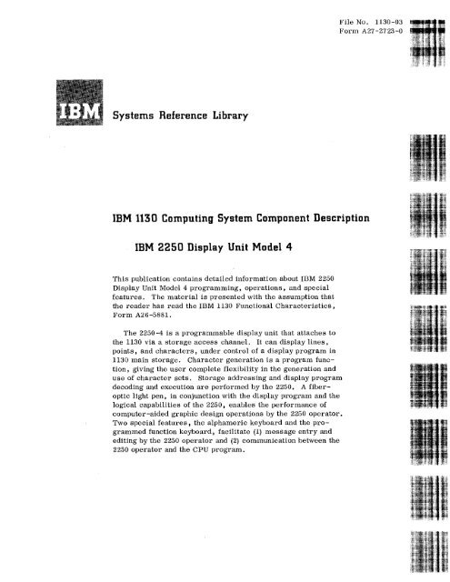
This publication contains detailed information <strong>about</strong> <strong>IBM</strong> <strong>2250</strong><br />
<strong>Display</strong> <strong>Unit</strong> <strong>Model</strong> 4 programming, operations, and special<br />
features. The material is presented with <strong>the</strong> assumption that<br />
<strong>the</strong> reader has read <strong>the</strong> <strong>IBM</strong> <strong>1130</strong> Functional Characteristics,<br />
Form A26-5881.<br />
The <strong>2250</strong>-4 is a programmable display unit that attaches to<br />
<strong>the</strong> <strong>1130</strong> via a storage access channel. It can display lines,<br />
points, and characters, under control of a display program in<br />
<strong>1130</strong> main storage. Character generation is a program function,<br />
giving <strong>the</strong> user complete flexibility in <strong>the</strong> generation and<br />
use of character sets. Storage addressing and display program<br />
decoding and execution are performed by <strong>the</strong> <strong>2250</strong>, A fiberoptic<br />
light pen, in conjunction with <strong>the</strong> display program and <strong>the</strong><br />
logical capabilities of <strong>the</strong> <strong>2250</strong>, enables <strong>the</strong> performance of<br />
computer-aided graphic design operations by <strong>the</strong> <strong>2250</strong> operator.<br />
Two special features, <strong>the</strong> alphameric keyboard and <strong>the</strong> programmed<br />
function keyboard, facilitate (1) message entry and<br />
editing by <strong>the</strong> <strong>2250</strong> operator and (2) communication between <strong>the</strong><br />
<strong>2250</strong> operator and <strong>the</strong> CPU program.
First Edition<br />
Specifications contained herein are subject<br />
to change from time to time. Any such<br />
change will be reported in subsequent<br />
revisions or Technical Newsletters.<br />
Copies of this and o<strong>the</strong>r <strong>IBM</strong> Publications can be obtained through <strong>IBM</strong> Branch Offices.<br />
Address comments concerning <strong>the</strong> contents of this publication to:<br />
<strong>IBM</strong> Corporation, Product Publications, Dept. 528, Kingston, New York 12401<br />
0 International Business Machines Corporation 1967
CONTENTS<br />
INTRODUCTION 5<br />
<strong>2250</strong>-4 DISPLAY SECTION 8<br />
<strong>Display</strong>s 9<br />
Graphic Mode 9<br />
Character Mode 11<br />
Light Pen 13<br />
Alphameric Keyboard 13<br />
Programmed Function Keyboard . . . . . 15<br />
<strong>2250</strong> Operator Control 16<br />
Metering 16<br />
<strong>2250</strong>-4 CHANNEL INTERFACE SECTION 17<br />
General 17<br />
Subroutines 18<br />
Graphic Subroutines 18<br />
Character Generation 18<br />
<strong>Display</strong> Orders 19<br />
Set Graphic Mode (Vector/Point) (SGMV, SGMP). 19<br />
Long Absolute XY (MBA, DBA) 19<br />
Short Absolute X/Y (MBAX, MBAY, DBAX, DBAY) . 19<br />
Incremental XY (MBI, DBI) 19<br />
Set Character Mode (Basic/Large) (SCMB, SCML). 20<br />
Stroke Data (MBS, DBS) 21<br />
Character Control Words (CS) 22<br />
Control Orders 23<br />
Branch and Interrupt Orders 23<br />
Short Branch (GSB) 23<br />
Long Branch/Interrupt (GB, GBE, GBC, GBCE,<br />
GI, GIC) 23<br />
Set Pen Mode (SPM, GNOP) 25<br />
Start Timer (STMR) 25<br />
Subroutine Linkage Orders 26<br />
Revert (RVT) 26<br />
Store Revert Register (SRVT) 26<br />
<strong>2250</strong>-4 OPERATIONS WITH THE <strong>1130</strong> 27<br />
Commands 27<br />
Initiate Write 27<br />
Start Regeneration 27<br />
Set Programmed Function Indicators 27<br />
Read Status 28<br />
Control 29<br />
No Operation 29<br />
Reset <strong>Display</strong> 29<br />
Sense Interrupt 30<br />
Sense DSW 30<br />
Interrupts 31<br />
Order Controlled Interrupt 31<br />
Keyboard Interrupt 31<br />
Detect Interrupt 32<br />
Error Recovery Procedures 32<br />
APPENDIX A. HEXADECIMAL - DECIMAL CONVERSION . 33<br />
ILLUSTRATIONS<br />
Frontispiece <strong>IBM</strong> <strong>2250</strong> <strong>Display</strong> <strong>Unit</strong> <strong>Model</strong> 4<br />
1 Typical <strong>1130</strong>/<strong>2250</strong>-4 System<br />
Configurations<br />
2 Functional Sections of <strong>2250</strong>-4<br />
3 <strong>Display</strong> Area Coordinate Addressing<br />
System<br />
4 Extended Grid for Incremental Deflection<br />
Off <strong>Display</strong> Area<br />
5 Character Grid Coordinate System •<br />
6 Strokes That Form'<strong>the</strong> Letter "A" . .<br />
7<br />
8<br />
5 9<br />
8 10<br />
11<br />
9<br />
12<br />
10<br />
11 13<br />
12<br />
Character <strong>Display</strong> Characteristics . . 12<br />
Fiber Optic Light Pen 14<br />
Alphameric Keyboard 14<br />
Programmed Function Keyboard . . . 15<br />
Decimal-Hexadecimal Conversion Chart<br />
for Incremental Orders 21<br />
Programmed Function Keyboard Overlay<br />
(Top View) 29<br />
Alphameric Keyboard Code Assignments. 29
<strong>IBM</strong> <strong>2250</strong> <strong>Display</strong> <strong>Unit</strong> <strong>Model</strong> 4
INTRODUCTION<br />
The <strong>IBM</strong> <strong>2250</strong> <strong>Display</strong> <strong>Unit</strong> <strong>Model</strong> 4 (Frontispiece)<br />
is a programmable device which attaches to <strong>the</strong><br />
<strong>IBM</strong> <strong>1130</strong> computing system and operates under<br />
control of a stored program in <strong>the</strong> 1131 Central<br />
Processing <strong>Unit</strong> (CPU). Two basic <strong>2250</strong>-4/<strong>1130</strong><br />
system configurations (Figure 1) are available to<br />
supplement <strong>IBM</strong>'s display products: (1) a standalone<br />
configuration, in which <strong>the</strong> <strong>1130</strong> is <strong>the</strong> host<br />
processor, and (2) a remote configuration, in which<br />
<strong>the</strong> <strong>1130</strong> attaches to <strong>IBM</strong> System/360 via <strong>the</strong> <strong>1130</strong><br />
synchronous communications adapter and an <strong>IBM</strong><br />
2701 Data Adapter <strong>Unit</strong>.<br />
The remote configuration, which enables<br />
installation of <strong>the</strong> <strong>2250</strong>-4 at a location remote from<br />
<strong>the</strong> System/360, provides a user situated distant<br />
from <strong>the</strong> central computer convenient access to<br />
powerful graphic data processing facilities. In this<br />
configuration, <strong>the</strong> <strong>1130</strong> can function as a dedicated<br />
graphics processor, performing unique graphic<br />
functions such as light-pen tracking, image<br />
selection, and display manipulation. In addition, <strong>the</strong><br />
central computer would be used for computational<br />
operations and for access to large data bases.<br />
Thus, <strong>the</strong> <strong>1130</strong> can (1) respond rapidly to display<br />
and conversational functions which, by virtue of<br />
<strong>the</strong>ir association with <strong>the</strong> user require fast response<br />
(in milliseconds), and (2) refer <strong>the</strong> computational<br />
functions for which <strong>the</strong> user can tolerate significantly<br />
a. Stand-Alone Configurations<br />
1132<br />
Printer<br />
1442 Card<br />
Read/Punch<br />
1131 CPU<br />
Disk<br />
SAC<br />
1627<br />
Plotter<br />
2310 Disk<br />
1133<br />
-- --- ---- ----<br />
SAC II<br />
<strong>2250</strong>-4<br />
b. Remote Configuration<br />
<strong>IBM</strong> System/360<br />
<strong>IBM</strong> 2701<br />
Data<br />
Adapter<br />
Un it<br />
Disk J<br />
Multiplexer<br />
Channel<br />
1131 CPU<br />
-----I<br />
Synchronous<br />
To 1133<br />
Data<br />
Data<br />
Set Set Data<br />
or <strong>2250</strong>-4<br />
Adapter<br />
To o<strong>the</strong>r I/0<br />
Figure 1. Typical <strong>1130</strong>/<strong>2250</strong>-4 System Configurations<br />
Introduction 5
longer delays (in seconds or minutes) to System/360<br />
for execution.<br />
The stand-alone configuration is a low-cost<br />
graphic data processing system which makes <strong>the</strong><br />
advantages of graphic data processing available to<br />
more users. In this configuration, <strong>the</strong> complete<br />
graphics application, including unique graphic<br />
functions and computational operations, can be<br />
performed by <strong>the</strong> <strong>1130</strong>.<br />
In ei<strong>the</strong>r configuration, <strong>the</strong> <strong>1130</strong> can function as<br />
a general-purpose computing system. It is<br />
available with a variety of input/output (I/O) devices<br />
and with comprehensive programming support.<br />
The <strong>2250</strong>/<strong>1130</strong> system offers fast man-machine<br />
communication and direct program control. The<br />
user can communicate with <strong>the</strong> computer in his<br />
natural technical language during execution of his<br />
problem. Logical capabilities in <strong>the</strong> <strong>2250</strong> enable<br />
<strong>the</strong> CPU program to effectively interpret user<br />
actions in connection with displayed images. In<br />
addition, <strong>the</strong> <strong>1130</strong> performs fast interrupt processing,<br />
and CPU processing can be overlapped<br />
with display program operations. Thus, <strong>the</strong> combined<br />
<strong>1130</strong> and <strong>2250</strong> form an effective and balanced<br />
graphic processing system.<br />
The <strong>2250</strong>-4 is a sit-down cathode-ray tube (CRT)<br />
display console for a single user. In addition to<br />
displaying graphic and alphameric information, <strong>the</strong><br />
<strong>2250</strong> offers man-machine interaction through its<br />
light pen (standard feature) and two keyboards<br />
(special features). Using <strong>the</strong>se facilities, a programmer<br />
can furnish computer-aided design<br />
capabilities whereby <strong>the</strong> <strong>2250</strong> user can create,<br />
modify, and add graphic and alphameric data into<br />
<strong>the</strong> system through <strong>the</strong> display screen.<br />
The <strong>2250</strong> attaches to <strong>the</strong> <strong>1130</strong> via a <strong>1130</strong> Storage<br />
Access Channel (SAC or SAC II) as shown in<br />
Figure 1. The <strong>1130</strong> operates and controls <strong>the</strong> <strong>2250</strong><br />
through commands and through a display order program<br />
sent from CPU storage to <strong>the</strong> <strong>2250</strong> via SAC.<br />
A display program comprising a series of orders<br />
(intermixed image and control information) can be<br />
sent to <strong>the</strong> <strong>2250</strong> up to 40 times a second (25ms<br />
frame time). This arrangement enables <strong>1130</strong> and<br />
<strong>2250</strong> operations to be asynchronous. Once <strong>2250</strong><br />
operations have been started, <strong>the</strong> <strong>2250</strong> addresses<br />
CPU storage as required to execute <strong>the</strong> display<br />
program, stealing memory cycles from <strong>the</strong> CPU<br />
without CPU program intervention. In <strong>the</strong> <strong>1130</strong><br />
system, I/O devices have higher cycle-stealing<br />
priority than <strong>the</strong> CPU; thus, memory-cycle<br />
demands by <strong>the</strong> <strong>2250</strong> always have higher priority<br />
than those of <strong>the</strong> CPU program. Note that <strong>2250</strong><br />
cycle-stealing is prevented from causing significant<br />
interference with o<strong>the</strong>r <strong>1130</strong> I/0 device operations;<br />
devices that operate synchronously with <strong>the</strong> CPU<br />
are assigned higher priority than <strong>the</strong> <strong>2250</strong> to<br />
eliminate <strong>2250</strong> interference with synchronous<br />
operations.<br />
Images in <strong>the</strong> form of alphameric characters,<br />
straight lines, and points are displayed on <strong>the</strong><br />
12-inch by 12-inch area of <strong>the</strong> CRT screen. This<br />
display area is divided into a 1,024X-by-1,024Y<br />
position grid. Points can be plotted at any intersection<br />
on this grid, and straight-line segments<br />
can be drawn between any two intersections;<br />
absolute and incremental positioning can be specified<br />
by image information from <strong>the</strong> display program.<br />
Character generation is a programmable<br />
function, giving <strong>the</strong> user complete flexibility in <strong>the</strong><br />
generation and use of character sets. Characters<br />
represented by <strong>the</strong>ir component strokes are stored<br />
as subroutines in CPU storage. In addition, <strong>the</strong><br />
capability to subscript and superscript characters<br />
is provided. These capabilities are particularly<br />
important in scientific applications that require<br />
<strong>the</strong> display of special symbols (such as Greek<br />
alphabetics). Inherently upper and lower-case is<br />
part of this programmable character set feature.<br />
The fiber-optic light pen provided, toge<strong>the</strong>r with<br />
<strong>the</strong> logical capabilities of <strong>the</strong> <strong>2250</strong>, enable <strong>the</strong> user<br />
to identify elements of displayed data to ei<strong>the</strong>r <strong>the</strong><br />
display program or <strong>the</strong> CPU program. Light-pen<br />
operations are enabled and controlled by <strong>the</strong> display<br />
program. The user can identify an element ei<strong>the</strong>r<br />
by pointing <strong>the</strong> light pen at <strong>the</strong> element and causing<br />
depression of <strong>the</strong> tip switch at <strong>the</strong> end of <strong>the</strong> pen or<br />
by pointing <strong>the</strong> pen at <strong>the</strong> element; <strong>the</strong> method of<br />
identification is determined by <strong>the</strong> display program.<br />
Two special features are available for <strong>the</strong> <strong>2250</strong>:<br />
(1) <strong>the</strong> alphameric keyboard, for message entry and<br />
editing, and (2) <strong>the</strong> programmed function keyboard,<br />
for application flexibility. With <strong>the</strong> typewriter-like<br />
alphameric keyboard, <strong>the</strong> user can enter alphameric<br />
messages consisting of letters, numbers, and/or<br />
special symbols into <strong>the</strong> display program for display<br />
and editing. The programmed function keyboard<br />
provides communication between <strong>the</strong> user and a<br />
CPU program. The keyboard consists of keys,<br />
indicators, and sensing switches for use with<br />
replaceable descriptive overlays. The function of<br />
each key and indicator is defined by <strong>the</strong> CPU program.<br />
Punches in <strong>the</strong> top edge of each overlay<br />
identify <strong>the</strong> overlay to <strong>the</strong> CPU program; key and/or<br />
indicator labels can be placed on <strong>the</strong> overlay to<br />
identify <strong>the</strong> key and indicator functions to <strong>the</strong><br />
operator. Each key can be used by <strong>the</strong> program to<br />
initiate a subroutine associated with <strong>the</strong> respective<br />
overlay, <strong>the</strong>reby performing <strong>the</strong> indicated function.<br />
For example, depression of a key might result in<br />
<strong>the</strong> enlargement, reduction, or deletion of <strong>the</strong><br />
displayed image.<br />
The <strong>1130</strong>/<strong>2250</strong> system is personalized and<br />
6
compact. Because <strong>the</strong> <strong>2250</strong> is located close to <strong>the</strong><br />
<strong>1130</strong>, <strong>the</strong> system can be operated as a single unit.<br />
The extended table top on <strong>the</strong> <strong>2250</strong> provides a convenient<br />
workspace for <strong>the</strong> system user. In addition,<br />
<strong>the</strong> 1131's internal disk drive is easily accessible<br />
from <strong>the</strong> display user position; thus, <strong>the</strong> user has<br />
easy access to removable 2315 disk cartridges,<br />
which can be used to retain data and programs<br />
relating to his applications.<br />
The logical capabilities of <strong>the</strong> <strong>2250</strong>, combined<br />
with <strong>the</strong> stored program facility provided by <strong>the</strong><br />
<strong>1130</strong>, allow <strong>the</strong> user great flexibility in designing<br />
his "man-machine" interface. The simplicity and<br />
versatility of <strong>the</strong> <strong>1130</strong> and its programming support<br />
enable <strong>the</strong> user to take advantage of this inherent<br />
flexibility.<br />
Introduction 7
<strong>2250</strong>-4 DISPLAY SECTION<br />
The <strong>2250</strong>-4, under control of <strong>the</strong> display program<br />
in <strong>1130</strong> storage, generates images on <strong>the</strong> 12-inch<br />
by 12-inch usable display area of a 21-inch cathoderay-tube<br />
(CRT). An image can comprise straight<br />
lines (vectors), points, and characters.<br />
A visible display is produced when an electron<br />
beam in <strong>the</strong> CRT strikes <strong>the</strong> phosphor-coated CRT<br />
screen, causing <strong>the</strong> portion of <strong>the</strong> coating struck<br />
by <strong>the</strong> beam to glow briefly. Normally, <strong>the</strong> glow<br />
fades within a fraction of a second, too soon for <strong>the</strong><br />
human eye to carefully perceive and identify <strong>the</strong><br />
image. For this reason, <strong>the</strong> display must be<br />
redrawn continuously (regenerated) at a rate that<br />
will cause <strong>the</strong> display to appear steady and sta-<br />
tionary to <strong>the</strong> observer. Regeneration is performed<br />
automatically under control of <strong>the</strong> display<br />
program.<br />
Storage addressing is performed in <strong>the</strong> <strong>2250</strong><br />
channel interface section (Figure 2). Once regeneration<br />
is started by an <strong>1130</strong> I/0 control command,<br />
<strong>the</strong> <strong>2250</strong> channel interface section continuously<br />
fetches orders and data from <strong>the</strong> display program<br />
in storage. Orders are decoded in this section,<br />
and deflection information is transferred to <strong>the</strong><br />
<strong>2250</strong> display section, where it is used to draw <strong>the</strong><br />
appropriate display. Regeneration is accomplished<br />
by continuously repeating <strong>the</strong> display program.<br />
Orders and data in <strong>the</strong> display program can be<br />
[<br />
Into rupt<br />
Control<br />
Address<br />
Decode<br />
Storage<br />
Buffer<br />
Register<br />
A<br />
1131<br />
Storage Access Channel<br />
<strong>2250</strong>-4<br />
Address<br />
Register<br />
Data Register<br />
Channel<br />
Interface<br />
Section<br />
Revert<br />
Register<br />
<strong>Display</strong><br />
Section<br />
Intensity<br />
Stroke<br />
Register<br />
Character<br />
Stroke<br />
Deflection<br />
X<br />
Deflection<br />
Deflection<br />
Register<br />
Register<br />
r 1<br />
Main Deflection<br />
Light Pen<br />
Control<br />
Various<br />
Light<br />
Alphameric<br />
Pen I Keyboard I<br />
I<br />
I<br />
I<br />
Programmed I<br />
Function I<br />
Keyboard I<br />
Figure 2. Functional Sections of <strong>2250</strong>-4<br />
8
modified during regeneration, as directed by <strong>the</strong><br />
CPU program or by <strong>the</strong> display program itself, to<br />
update or change <strong>the</strong> display.<br />
The <strong>2250</strong> display section also performs various<br />
nondisplay services for <strong>the</strong> user by providing <strong>the</strong><br />
interface between <strong>the</strong> user and <strong>the</strong> problem program<br />
with <strong>the</strong> following devices:<br />
1. Programmed function keyboard. Provides<br />
keys and overlays (for user communication to<br />
<strong>the</strong> program) and indicators (for program<br />
communication to <strong>the</strong> user).<br />
2. Alphameric keyboard. Enables <strong>the</strong> user to<br />
change, edit, and/or create character<br />
displays. Note that alphameric keyboard key<br />
codes can be interpreted by <strong>the</strong> CPU program<br />
and used for control purposes in a<br />
manner similar to operations with <strong>the</strong> programmed<br />
function keyboard.<br />
3. Light pen. Provides <strong>the</strong> means by which <strong>the</strong><br />
program can identify <strong>the</strong> storage address of<br />
<strong>the</strong> order that initiated display of a vector,<br />
point, or character at which <strong>the</strong> user is pointing<br />
a pen-like device. This information can<br />
be used for operations as determined by <strong>the</strong><br />
display program, by <strong>the</strong> alphameric keyboard,<br />
or by <strong>the</strong> programmed function keyboard.<br />
Thus, <strong>the</strong> light pen enables <strong>the</strong> user to enter<br />
and manipulate graphic information.<br />
DISPLAYS<br />
Information positioning on <strong>the</strong> <strong>2250</strong> display area is<br />
controlled by a display program in <strong>1130</strong> storage.<br />
This program is sent to <strong>the</strong> <strong>2250</strong>, by 16-bit word,<br />
via <strong>the</strong> <strong>1130</strong> storage access channel. Orders in<br />
this program specify electron beam deflection to<br />
horizontal (X) and vertical (Y) coordinates on a<br />
square grid composed of possible electron-beamdeflection<br />
end points. This grid, called <strong>the</strong><br />
"reference grid", covers (logically) <strong>the</strong> 12-inch by<br />
12-inch display area on <strong>the</strong> face of <strong>the</strong> CRT; it<br />
comprises 1,024 equally spaced X positions and<br />
1,024 equally spaced Y positions (Figure 3).<br />
Positioning orders in <strong>the</strong> display program select<br />
<strong>the</strong> X and Y coordinates for each element of a <strong>2250</strong><br />
display (each point, line end point, and character<br />
area centroid). The grid of addressable coordinates<br />
is called a "raster". The distance between two<br />
sequentially addressable lines on <strong>the</strong> raster is<br />
called a "raster unit". Thus, a raster unit represents<br />
1/1,023 of <strong>the</strong> image (in ei<strong>the</strong>r <strong>the</strong> X or <strong>the</strong><br />
Y direction).<br />
The <strong>2250</strong> can display information in ei<strong>the</strong>r of two<br />
modes: Graphic or Character. Graphic mode is <strong>the</strong><br />
normal <strong>2250</strong> mode of operation. As such, it is<br />
retained through interrupts and Character mode<br />
operations, even when it has not been set previously.<br />
Y Axis<br />
1023<br />
0512<br />
0256 —<br />
0128 —<br />
0064 -<br />
0000<br />
0000 10128<br />
0064<br />
X = 0256<br />
Y = 0512<br />
0256 C,112<br />
X Axis<br />
Note: One raster unit = 0.0117 inch, 85 raster units = 1.0 inch,<br />
and 1023 raster units = 12 inches.<br />
Figure 3. <strong>Display</strong> Area Coordinate Addressing System<br />
Graphic Mode<br />
1023<br />
Ei<strong>the</strong>r vector or point operations can be performed<br />
by <strong>the</strong> <strong>2250</strong> in Graphic mode; if no specific Graphic<br />
mode has been set previously by an order from <strong>the</strong><br />
display program, Vector mode is set automatically.<br />
In Graphic mode, <strong>the</strong> <strong>2250</strong> can receive, from <strong>the</strong><br />
display program, ei<strong>the</strong>r (1) electron beam positioning<br />
orders, or (2) an order to establish a different<br />
mode of operation, such as to set Point mode from<br />
Vector mode or to enter Character mode from<br />
Graphic mode.<br />
When <strong>the</strong> <strong>2250</strong> is in Graphic mode, positioning<br />
orders from <strong>the</strong> display program directs electron<br />
beam movement (deflection) on <strong>the</strong> reference grid.<br />
Positioning orders address <strong>the</strong> X, Y coordinates to<br />
which <strong>the</strong> electron beam is to be repositioned.<br />
Beam deflection is always from <strong>the</strong> previously<br />
addressed coordinates (where <strong>the</strong> beam is currently<br />
positioned) to <strong>the</strong> new coordinates. If <strong>the</strong> <strong>2250</strong> is in<br />
Vector mode and a vector is to be displayed, <strong>the</strong><br />
beam is turned on (unblanked) as it is being<br />
repositioned, displaying a line between <strong>the</strong> current<br />
position and <strong>the</strong> new position specified; in point mode,<br />
<strong>the</strong> beam is unblanked after it has been repositioned,<br />
displaying a point at <strong>the</strong> new position. Points plotted<br />
4 or more raster units apart can be distinguished by<br />
<strong>the</strong> viewer as distinct points.<br />
Positioning orders can also reposition <strong>the</strong><br />
electron beam without causing a visible line or point<br />
to appear on <strong>the</strong> display. This capability is used<br />
to select a starting location for displaying charac-<br />
<strong>2250</strong>-4 <strong>Display</strong> Section 9
ters or to start <strong>the</strong> display of a new set of vectors<br />
or points. The positioning order for each vector<br />
and point contains a beam control bit, which<br />
specifies whe<strong>the</strong>r <strong>the</strong> <strong>2250</strong> is to display <strong>the</strong><br />
associated vector or point or is to reposition <strong>the</strong><br />
beam without causing a display.<br />
The positioning order for each deflection specifies<br />
not only <strong>the</strong> new beam position and beam condition;<br />
it also specifies <strong>the</strong> format in which <strong>the</strong> new<br />
position is presented. The new position for each<br />
deflection can be presented in any of three formats:<br />
long absolute, short absolute, or incremental.<br />
Operations performed by <strong>the</strong> <strong>2250</strong> are different for<br />
each type of order.<br />
Long-absolute orders specify <strong>the</strong> actual X, Y<br />
coordinates to which <strong>the</strong> beam is to be deflected.<br />
Each pair of long-absolute order words addresses<br />
one pair of coordinates on <strong>the</strong> reference grid (e. g. ,<br />
X = 0512, Y = 1016). Any grid position can be<br />
addressed, and a deflection of any length and in any<br />
direction can be specified.<br />
Short-absolute orders specify deflection ei<strong>the</strong>r<br />
in <strong>the</strong> horizontal (X) direction or in <strong>the</strong> vertical (Y)<br />
direction, but not both. Each short-absolute order<br />
addresses one X or Y coordinate on <strong>the</strong> reference<br />
grid; <strong>the</strong> axis not specified in <strong>the</strong> data remains<br />
unchanged. The beam is deflected horizontally or<br />
vertically to <strong>the</strong> addressed coordinate. For<br />
example, if <strong>the</strong> beam is at position X = 0512,<br />
Y = 0512, only four short-absolute orders are<br />
needed to draw a box; each order might specify a<br />
coordinate as follows:<br />
1. Y = 0612<br />
2. X = 0612<br />
3. Y = 0512<br />
4. X = 0512<br />
Incremental positioning orders specify <strong>the</strong><br />
amount and direction of beam deflection relative to<br />
<strong>the</strong> current beam position. Each incremental order<br />
specifies one increment (up to X = +63 or -64,<br />
Y = +63 or -64, a displacement of 0.74 inch) of<br />
beam deflection. For example, if <strong>the</strong> current beam<br />
position on <strong>the</strong> reference grid is X = 0512, Y = 1016,<br />
and if an incremental order specifies X = +20,<br />
Y = -40, beam deflection will be to position X = 0532,<br />
Y = 0976 on <strong>the</strong> reference grid. Thus, <strong>the</strong> tX, ±Y<br />
incremental value is added to <strong>the</strong> absolute value of<br />
<strong>the</strong> current beam position, resulting in a new<br />
absolute value for <strong>the</strong> new beam position.<br />
When incremental orders cause <strong>the</strong> beam to<br />
move outside <strong>the</strong> reference grid area, and when<br />
a total displacement of 1,024 raster units beyond<br />
<strong>the</strong> perimeter in <strong>the</strong> X or Y direction is not<br />
exceeded, <strong>the</strong> vectors and/or points so displaced<br />
will be blanked and <strong>the</strong> X and/or Y overflow bit(s)<br />
will be set. In this case <strong>the</strong> X, Y deflection<br />
registers will contain <strong>the</strong> value of a wraparound<br />
position; e. g. , when <strong>the</strong> beam is moved 10 raster<br />
units in <strong>the</strong> +X direction from position X = 1023,<br />
Y = N, <strong>the</strong> wraparound position is X = 10, Y = N,<br />
and <strong>the</strong> X overflow bit is set. Unless <strong>the</strong> overflow<br />
limit of 1,024 raster units is exceeded (Figure 4),<br />
<strong>the</strong> displaced beam can be returned to <strong>the</strong> normal<br />
grid area; <strong>the</strong>n, displaying will resume when a<br />
positioning order specifies an unblanked deflection<br />
that is entirely within <strong>the</strong> normal display area.<br />
Y Axis<br />
-1024 0 -1023 1-2047<br />
X Axi,<br />
Note: Using Incremental Graphic orders and/or incrementally positioned characters,<br />
any element within <strong>the</strong> double-crosshatched area can be displayed on <strong>the</strong><br />
image area without causing wraparound .<br />
Figure 4. Extended Grid for Incremental Deflection Off <strong>Display</strong><br />
Area<br />
When a portion of a display is blanked because<br />
of a beam displacement condition, <strong>the</strong> display program<br />
can return that portion to <strong>the</strong> visible display<br />
area by issuing (1) a long-• absolute order, (2) incremental<br />
orders in <strong>the</strong> opposite direction, or (3) one<br />
or two short--absolute orders, depending on<br />
whe<strong>the</strong>r <strong>the</strong> beam is off in one direction (X or Y) or<br />
is off in both directions (X and Y).<br />
Electron beam deflection to <strong>the</strong> previously<br />
addressed coordinate can still be in progress when<br />
<strong>the</strong> next coordinate data is received. When <strong>the</strong><br />
deflection currently in process is completed, <strong>the</strong><br />
beam bit is sent to <strong>the</strong> intensity control section, and<br />
<strong>the</strong> new X, Y coordinates are sent to <strong>the</strong> main<br />
deflection section.<br />
The main deflection section applies X and Y<br />
analog values for <strong>the</strong> current beam position to <strong>the</strong><br />
deflection coil of <strong>the</strong> CRT until a new positioning<br />
order is received, at which time <strong>the</strong> analog values<br />
start changing to reflect <strong>the</strong> new position. As <strong>the</strong><br />
analog values change, <strong>the</strong> beam moves, causing <strong>the</strong><br />
10
image to be displayed. If <strong>the</strong> beam bit specifies<br />
a blanked deflection, <strong>the</strong> beam moves without<br />
being displayed. If <strong>the</strong> beam bit specifies an<br />
unblanked deflection, <strong>the</strong> electron beam is moved<br />
and unblanked as required to display a vector or<br />
point.<br />
The X and Y position registers always contain<br />
<strong>the</strong> absolute X, Y address of <strong>the</strong> current beam<br />
position in digital form; <strong>the</strong> contents of <strong>the</strong>se<br />
registers can be retrieved to reconstruct <strong>the</strong> most<br />
recent positioning data.<br />
Note that long-absolute, short-absolute, and<br />
incremental orders can be intermixed since each<br />
is uniquely identified and does not require a mode<br />
to be set. In addition, any nongraphic order can<br />
be intermixed with graphic data without terminating<br />
<strong>the</strong> Graphic mode (point or vector).<br />
110<br />
101<br />
100<br />
Last Graphic Coordinate<br />
(X = 0205, se 0512)<br />
110<br />
101<br />
100<br />
Character Grid Area--<br />
0512<br />
Reference Grid<br />
0205<br />
Character Mode<br />
The set of characters that can be displayed by <strong>the</strong><br />
<strong>2250</strong> in Character mode is defined by <strong>the</strong> programmer.<br />
This character set resides in <strong>1130</strong><br />
storage as a subroutine of <strong>the</strong> display program and<br />
can comprise any number of characters in any font;<br />
<strong>the</strong>se characters can be modified at any time during<br />
execution of <strong>the</strong> display program. Characters in<br />
this set can be displayed in ei<strong>the</strong>r of two sizes,<br />
basic or large, as determined by <strong>the</strong> character mode<br />
order.<br />
In Character mode, <strong>the</strong> current X, Y position<br />
of <strong>the</strong> beam on <strong>the</strong> 1,024-by-1,024 position display<br />
area becomes <strong>the</strong> center of a basic-size or largesize<br />
character area, which is maintained throughout<br />
one Character mode operation. The program<br />
normally places <strong>the</strong> beam at a starting position on<br />
<strong>the</strong> display area (using a blanked point or vector)<br />
before a character display operation is started.<br />
The character area is divided into a grid format<br />
of 6X-by-7Y addressable points (Figure 5); note<br />
that character grid points do not coincide with <strong>the</strong><br />
1,024-by-1,024 points on <strong>the</strong> reference grid. A<br />
character is drawn in this area with a series of<br />
high-speed deflections, or "strokes". An average<br />
of six such strokes is required to form one uppercase<br />
character; lower-case characters may require<br />
more strokes. Two stroke end points are specified<br />
in each word of stroke data from <strong>the</strong> display program.<br />
The character deflection section (Figure 2)<br />
converts each stroke end point to X and Y analog<br />
signals; <strong>the</strong>se are applied to <strong>the</strong> high-speed<br />
character stroke deflection coil of <strong>the</strong> CRT.<br />
The main deflection system and <strong>the</strong> character<br />
deflection system operate independently. The main<br />
deflection system maintains <strong>the</strong> current beam<br />
position (<strong>the</strong> center point of <strong>the</strong> character grid) by<br />
supplying a constant X and Y analog current to <strong>the</strong><br />
Y Axis<br />
011<br />
010<br />
001<br />
011<br />
010<br />
001<br />
Basic<br />
000<br />
000 001<br />
Large<br />
000<br />
000 001 010 011 100 101<br />
X Axis<br />
Figure 5. Character Grid Coordinate System<br />
010 0 1 100 101 110<br />
main deflection yoke. At <strong>the</strong> same time, <strong>the</strong><br />
character deflection system offsets <strong>the</strong> beam to<br />
position X = 000, Y = 000 of <strong>the</strong> character grid upon<br />
entering Character mode and <strong>the</strong>n forms a character<br />
by moving <strong>the</strong> beam at high speed between various<br />
addressed points in <strong>the</strong> character grid area.<br />
Figure 6 illustrates <strong>the</strong> strokes used to form <strong>the</strong><br />
character "A".<br />
Figure 7 shows <strong>the</strong> characteristics of a<br />
character display. Character spacing is an automatic<br />
function of <strong>the</strong> <strong>2250</strong>. A special bit, called<br />
<strong>the</strong> "revert" bit, is set in <strong>the</strong> last data word for<br />
each character. (The revert bit is used during<br />
o<strong>the</strong>r operations, as described later in this document.)<br />
This bit causes <strong>the</strong> main deflection system<br />
to move <strong>the</strong> electron beam in <strong>the</strong> +X direction to<br />
<strong>the</strong> new character area center point. The beam is<br />
moved a distance of 14 raster units when displaying<br />
basic-size characters or 21 raster units when<br />
displaying large-size characters. The program can<br />
initiate additional spaces of 14 or 21 raster units<br />
110<br />
<strong>2250</strong>-4 <strong>Display</strong> Section 11
:Basic: 0.12" (nominal)<br />
- large: 0.18" (nominal)<br />
rim<br />
4■<br />
(I)<br />
A<br />
4 ■/ iii.<br />
Or<br />
•E►<br />
r 1<br />
0 I 2 3 4 5 6<br />
E 4--<br />
1411P A■<br />
v<br />
k •<br />
I 10<br />
A<br />
Nom<br />
'Al<br />
D<br />
MEM I up...<br />
ral<br />
gh,••o<br />
Graphic XY Position<br />
Legend<br />
Character Size<br />
Characteristics<br />
Basic Large<br />
Characters per Line (Max.) 74 49<br />
Lines per <strong>Display</strong> (Max.) 52 35<br />
Number of characters on d.sploy (max)* 11,848 1,715<br />
Character Grid:<br />
A Width 10 RU 15 RU<br />
I. Circled lill1111,1L refel to <strong>the</strong> SC(4,...11", in which<br />
<strong>the</strong> deflection end points ale addressed.<br />
2 Deflect ion oh occuts automatically upon entering<br />
Character mode. Deflection ba occurs when leaving<br />
Character mode, in grid position following lost<br />
character in sh ;lig.<br />
Figure 6. Strokes That Form <strong>the</strong> Letter "A"<br />
each by sending <strong>the</strong> <strong>2250</strong> one two-stroke character<br />
word for each space; this word would specify two<br />
blanked strokes and should have <strong>the</strong> revert bit set.<br />
Hence, one space character would result in a<br />
distance of 28 or 42 raster units between <strong>the</strong> center<br />
point of <strong>the</strong> previously specified character area<br />
and <strong>the</strong> center point of <strong>the</strong> next area.<br />
In addition to stroke words, <strong>the</strong> program can<br />
also send control words to <strong>the</strong> <strong>2250</strong> during<br />
Character mode operations. A control word specifies<br />
any one of five functions: new line, null,<br />
subscript, superscript, or no-operation. These<br />
functions are described in <strong>the</strong> following paragraphs.<br />
Initial character positioning can be accomplished<br />
by an absolute or incremental Graphic mode order.<br />
For establishing a method of line spacing, characters<br />
that follow a long-absolute order are considered<br />
to be "absolutely positioned," and<br />
characters that follow an incremental order are<br />
"incrementally positioned." Intervening shortabsolute<br />
orders, though executed, do not establish<br />
a method of line spacing; instead, <strong>the</strong> most recent<br />
long-absolute or incremental order is <strong>the</strong> determining<br />
factor.<br />
B Height 14 RU 21 RU<br />
C Character Spacing 14 RU 21 RU<br />
D Line Spacing 20 RU 30 RU<br />
L Horizontal Character <strong>Unit</strong> 1.7 RU 2.5 RU<br />
F Vertical Character <strong>Unit</strong> 2.0 RU 3.0 RU<br />
C X Offset 6.0 RU 9.0 RU<br />
II Y Offset 7.0 RU 10.5 RU<br />
I and J Superscript and Subscr ipt Offset 6 RU 9 RU<br />
1." Not flicker-free display<br />
Figure 7. Character <strong>Display</strong> Characteristics<br />
Line spacing is initiated ei<strong>the</strong>r by <strong>the</strong> display<br />
program or by <strong>the</strong> <strong>2250</strong>. A new line (NL) control<br />
word from <strong>the</strong> display program causes <strong>the</strong> <strong>2250</strong><br />
to reset <strong>the</strong> X deflection register to zero and to<br />
decrement <strong>the</strong> Y deflection register by 20 or 30<br />
raster units as determined by character size.<br />
Successive NL control words cause successive<br />
lines to be stepped. If <strong>the</strong> Y deflection register<br />
underflows (decrements below Y = 0000), and if <strong>the</strong><br />
characters were absolutely positioned, wraparound<br />
occurs so that <strong>the</strong> new line is positioned at <strong>the</strong> top<br />
of <strong>the</strong> display area. If underflow occurs during <strong>the</strong><br />
display of incrementally positioned characters,<br />
subsequent lines are positioned below <strong>the</strong> image<br />
area (Figure 4). In addition, subsequent characters<br />
are blanked until <strong>the</strong> beam is returned to <strong>the</strong> image<br />
area, ei<strong>the</strong>r by a second Y deflection register<br />
12
underflow (decremented to below Y = 1024) or by<br />
one or more Graphic mode orders.<br />
Automatic line spacing is performed during<br />
display of absolutely positioned characters whenever<br />
a character space operation causes <strong>the</strong> X<br />
deflection register to overflow (to increment above<br />
X = +1023). If an NL control word is not received,<br />
<strong>the</strong> <strong>2250</strong> (1) displays characters to <strong>the</strong> end of a<br />
line, (2) automatically resets <strong>the</strong> X deflection<br />
register to zero, (3) decrements <strong>the</strong> Y deflection<br />
register by 20 or 30 raster units, depending on<br />
character size, and (4) continues <strong>the</strong> display of<br />
characters.<br />
Automatic line spacing is not performed when<br />
incrementally positioned characters are displayed.<br />
In this case, <strong>the</strong> X deflection register is not reset<br />
if overflow occurs during character spacing. Thus,<br />
blanked characters are positioned to <strong>the</strong> right of<br />
<strong>the</strong> display area, in <strong>the</strong> same line. If <strong>the</strong> X<br />
deflection register overflows a second time (increments<br />
beyond X = 2047), wraparound occurs; <strong>the</strong><br />
line of characters reappears at <strong>the</strong> left side of <strong>the</strong><br />
visible image area. Note that <strong>the</strong> Y deflection<br />
register is not decremented; thus, line spacing does<br />
not occur. When outside <strong>the</strong> image area, in <strong>the</strong> X<br />
direction, <strong>the</strong> beam can be returned (1) by an NL<br />
control word, (2) by Graphic orders, or (3) by <strong>the</strong><br />
second X deflection register overflow.<br />
The null control word does not cause a display,<br />
does not affect <strong>the</strong> X, Y position registers, and does<br />
not cause character spacing. It can be used as <strong>the</strong><br />
last word of a character to permit superimposed<br />
characters and can be used in character strings to<br />
reserve storage space for characters added by <strong>the</strong><br />
operator.<br />
The subscript control word causes <strong>the</strong> character<br />
grid to be offset downward from its normal position<br />
by three vertical character units (Figure 7). The<br />
grid remains in this offset position (1) until a<br />
character space is performed (initiated by receipt<br />
of a stroke word with <strong>the</strong> revert bit set), (2) until<br />
a superscript control function is executed, and<br />
(3) until a null control function is executed. The<br />
subscript function enables <strong>the</strong> drawing of subscripts,<br />
of lower-case letters that extend below <strong>the</strong><br />
line, or of strokes (such as underlines) beneath<br />
normally positioned characters.<br />
The superscript control word causes <strong>the</strong> character<br />
grid to be offset upward from its normal<br />
position by three character units (Figure 7). The<br />
grid remains offset until a revert-initiated character<br />
space if performed or until subscript or null control<br />
function is executed. The superscript function<br />
enables <strong>the</strong> drawing of superscripts and of strokes<br />
above normally positioned characters.<br />
Control words that contain undefined codes are<br />
no-op'ed. However, a revert bit in <strong>the</strong>se words,<br />
if set, causes execution of <strong>the</strong> revert function.<br />
Thus, no-op's can be used to reserve CPU storage<br />
locations for later use by a program.<br />
LIGHT PEN<br />
The light pen, a fiber-optic device (Figure 8),<br />
provides two independent inputs to <strong>the</strong> <strong>2250</strong>; lightpen<br />
detect status and light-pen switch status. First,<br />
<strong>the</strong> user points <strong>the</strong> light pen at <strong>the</strong> section of<br />
displayed image he wants to identify to <strong>the</strong> display<br />
program or <strong>the</strong> CPU program. A light-pen detect<br />
can occur whenever light from <strong>the</strong> CRT beam passes<br />
within <strong>the</strong> light pen field of view. In addition, when<br />
<strong>the</strong> light pen is in <strong>the</strong> desired position, <strong>the</strong> user can<br />
press <strong>the</strong> pen tip against <strong>the</strong> CRT faceplate to<br />
activate <strong>the</strong> tip-switch.<br />
Activation of <strong>the</strong> light-pen switch and <strong>the</strong> occurrence<br />
of a light-pen detect are independent functions,<br />
and <strong>the</strong>ir significance is determined by <strong>the</strong> display<br />
program. The display program can disable (or<br />
ignore) light-pen detects and ignore switch<br />
closures, or it can establish that any one of <strong>the</strong><br />
following conditions is significant:<br />
1. Light-pen switch closed (detect or no detect).<br />
2. Light-pen detect (switch open or closed).<br />
3. Light pen detect and light pen switch closed.<br />
Following <strong>the</strong> occurrence of <strong>the</strong> significant condition(s),<br />
<strong>the</strong> program can interrupt <strong>the</strong> CPU or<br />
can branch operations to a new storage address.<br />
When light-pen detects are enabled (or made<br />
significant) by <strong>the</strong> program, a detect occurs each<br />
time <strong>the</strong> unblanked beam passes within <strong>the</strong> light pen<br />
field of view. This "continuous detects" mode can<br />
be used in graphic design operations such as light<br />
pen tracking. In addition, <strong>the</strong> display program can<br />
ignore <strong>the</strong> light pen while certain information (such<br />
as a background grid) is being displayed, inhibiting<br />
light-pen-initiated operations on that information.<br />
Two small beams of light projected by <strong>the</strong> light<br />
pen appear as two small dots on <strong>the</strong> CRT faceplate.<br />
These dots assist <strong>the</strong> user in aiming <strong>the</strong> light pen<br />
by "bracketing" <strong>the</strong> image section that is within <strong>the</strong><br />
light pen field of view.<br />
ALPHAMERIC KEYBOARD<br />
This special feature provides a typewriter-like<br />
keyboard with which <strong>the</strong> user can compose and/or<br />
modify messages (on <strong>the</strong> CRT display area) not<br />
protected by <strong>the</strong> CPU program from keyboard<br />
action. Identification (to <strong>the</strong> user) of <strong>the</strong> character<br />
or character position that can be modified or<br />
inserted by <strong>the</strong> keyboard is a program function.<br />
The keyboard (Figure 9) has 44 character keys<br />
and a SHIFT key, which provide a selection of 90<br />
EBCDIC characters (Figure 13). Each alphabetic<br />
<strong>2250</strong>-4 <strong>Display</strong> Station 13
Figure 8. Fiber Optic Light Pen<br />
Figure 9. Alphameric Keyboard<br />
14
key can provide <strong>the</strong> upper- or lower-case character<br />
as selected by <strong>the</strong> user. In addition to standard<br />
character keys, <strong>the</strong> following function keys are<br />
provided:<br />
SHIFT: When depressed, allows selection of<br />
any upper-case alphabetic character or any of <strong>the</strong><br />
upper characters identified on <strong>the</strong> dual-character<br />
keys. When released, any lower-case alphabetic<br />
character or lower dual-character-key character<br />
can be selected.<br />
LOCK: Holds SHIFT key in <strong>the</strong> down position.<br />
ALTN CODING: <strong>All</strong>ows selection of NULL, END,<br />
or CANCEL; when pressed with any o<strong>the</strong>r key,<br />
generates a null code.<br />
CONTINUE: When held down with a character<br />
or control key, <strong>the</strong> character or control key code<br />
is entered once per regeneration cycle until <strong>the</strong><br />
CONTINUE key is released.<br />
END, CANCEL, ADVANCE, BACKSPACE, and<br />
JUMP: The functions of <strong>the</strong>se keys are established<br />
by <strong>the</strong> CPU program. Each key sets a unique bit<br />
which can be retrieved by <strong>the</strong> program.<br />
Each time a key o<strong>the</strong>r than SHIFT, LOCK, ALTN<br />
CODING, or CONTINUE is depressed, <strong>the</strong> keyboard<br />
locks, regeneration is terminated at completion<br />
of <strong>the</strong> current cycle, and an interrupt is requested.<br />
The CPU program can respond to this request by<br />
issuing commands to read <strong>the</strong> key code and to<br />
unlock <strong>the</strong> keyboard.<br />
PROGRAMMED FUNCTION KEYBOARD<br />
The programmed function keyboard (Figure 10)<br />
contains 32 keys, 32 indicators, and eight switches<br />
which sense a code punched into <strong>the</strong> top edge of an<br />
overlay (Figure 12). The application program<br />
defines <strong>the</strong> function of each key and indicator. Each<br />
of 256 possible coded overlays identifies <strong>the</strong> function<br />
of <strong>the</strong> keys and indicators, both to <strong>the</strong> operator and<br />
to <strong>the</strong> CPU program; key and/or indicator labels<br />
can be placed on <strong>the</strong> overlays. Each key can be<br />
used by <strong>the</strong> program to initiate a subroutine associated<br />
with <strong>the</strong> respective overlay. When a key is<br />
pressed, <strong>the</strong> keyboard is electrically locked (keys<br />
can be pressed, but <strong>the</strong>y have no effect), regeneration<br />
is stopped, and a CPU interrupt is requested.<br />
The CPU program can respond to this interrupt by<br />
issuing an I/0 Control command (IOCC) to read <strong>the</strong><br />
key and overlay codes. Then, <strong>the</strong> CPU program<br />
can perform <strong>the</strong> indicated function and restart <strong>the</strong><br />
display, <strong>the</strong>reby unlocking <strong>the</strong> keyboard. For<br />
example, depression of a key might result in <strong>the</strong><br />
enlargement, reduction, or deletion of a displayed<br />
image.<br />
Plastic overlays (PN 5704496) are available<br />
directly from <strong>the</strong> DP Administration Operations<br />
Office (A00). One overlay punch (PN 5704549) per<br />
installation is furnished to each customer at no<br />
charge. Additional punches can be ordered on an<br />
Figure 10. Programmed Function Keyboard<br />
<strong>2250</strong>-4 <strong>Display</strong> Section 15
MES from <strong>IBM</strong> Kingston.<br />
Each of <strong>the</strong> 32 programmed function keyboard<br />
keys has a built-in indicator. Operation of <strong>the</strong>se<br />
indicators is independent of <strong>the</strong> operation of <strong>the</strong><br />
keys; however, <strong>the</strong> indicators can be used for<br />
associated functions such as informing <strong>the</strong> operator<br />
of <strong>the</strong> keys that can be, or have been, activated.<br />
<strong>2250</strong> OPERATOR CONTROL<br />
The <strong>2250</strong> is equipped with a BRIGHTNESS control<br />
with which <strong>the</strong> operator can adjust <strong>the</strong> light intensity<br />
of <strong>the</strong> overall display for a given regeneration<br />
rate. Improper adjustment of this control might<br />
result in faulty light pen operation.<br />
METERING<br />
The <strong>2250</strong> is metered as an assignable unit on <strong>the</strong><br />
<strong>1130</strong>. It contains a usage meter to record customer<br />
run time and an Enable/Disable switch. The <strong>2250</strong><br />
records time when all of <strong>the</strong> following conditions<br />
are met:<br />
1. Power is on (controlled at 1131).<br />
2. The <strong>2250</strong> is in <strong>the</strong> enabled state.<br />
3. The CPU or cycle-steal I/0 devices are<br />
running (not in CE mode). (Cycle-steal I/0<br />
devices include disks, 2501, 1403, 1132, and<br />
<strong>2250</strong>.)<br />
The Enable/Disable switch allows <strong>the</strong> <strong>2250</strong> to<br />
become logically enabled or disabled. When <strong>the</strong><br />
<strong>2250</strong> is logically disabled, <strong>the</strong> usage meter is<br />
prevented from recording time and <strong>the</strong> <strong>2250</strong> is<br />
prevented from operating; it is logically disconnected<br />
(off-line) from <strong>the</strong> <strong>1130</strong>, and signals are not<br />
transmitted across <strong>the</strong> interface. When <strong>the</strong> <strong>2250</strong><br />
is enabled, it is on-line, and <strong>the</strong> usage meter<br />
records time.<br />
The Enable/Disable switch setting may be<br />
changed at any time. However, <strong>the</strong> <strong>2250</strong> state does<br />
not change until <strong>the</strong> following conditions occur<br />
simultaneously for a minimum period of lusec:<br />
(1) <strong>the</strong> CPU is in <strong>the</strong> Wait state or in CE mode, and<br />
(2) all I/O operations (including those of <strong>the</strong> <strong>2250</strong>)<br />
are stopped. Note that <strong>the</strong> usage meter does not<br />
record time when <strong>the</strong> <strong>1130</strong> is in CE mode or when<br />
<strong>the</strong> CPU and cycle-steal I/0 devices are not<br />
running.<br />
16
Form A27-2723-0<br />
Page Revised 9/8/67<br />
By TNL N27-2915<br />
<strong>2250</strong>-4 CHANNEL INTERFACE SECTION<br />
GENERAL<br />
The <strong>2250</strong>-4 channel interface section (Figure 2)<br />
interfaces <strong>the</strong> storage access channel and <strong>the</strong> <strong>2250</strong>-4<br />
display section. It decodes and executes orders<br />
and commands, addresses CPU storage, and<br />
handles data transferred to or from CPU storage.<br />
Information transfer across <strong>the</strong> storage access<br />
channel/<strong>2250</strong> interface is by 16-bit word.<br />
An address register in <strong>the</strong> <strong>2250</strong> channel section<br />
specifies, to CPU storage, <strong>the</strong> location at which<br />
information will be stored or from which it will be<br />
retrieved for <strong>2250</strong> operations. This address<br />
register is loaded initially by an Initiate Write<br />
(Start Regeneration) command from <strong>the</strong> CPU program;<br />
it can <strong>the</strong>n be stepped automatically by <strong>the</strong><br />
<strong>2250</strong>, altered by <strong>the</strong> display program, or reloaded<br />
by <strong>the</strong> CPU program. Thus, display regeneration<br />
can be performed without CPU intervention.<br />
The display program consists of display orders,<br />
associated data for image generation, and control<br />
orders for various nondisplay functions. Table 1<br />
lists <strong>the</strong> <strong>2250</strong> order set. Undefined order codes<br />
received by <strong>the</strong> <strong>2250</strong> are treated as no-operation<br />
orders or are interpreted as data if in <strong>the</strong> appropriate<br />
format.<br />
The CPU program initiates <strong>2250</strong> operations by<br />
issuing an Execute I/0 (XIO) instruction. The I/0<br />
Control command (IOCC) at <strong>the</strong> effective storage<br />
address specified by MO is <strong>the</strong>n sent to <strong>the</strong> <strong>2250</strong>.<br />
If <strong>the</strong> IOCC is Initiate Write (Start Regeneration),<br />
<strong>the</strong> <strong>2250</strong> fetches display program information from<br />
main storage, starting at <strong>the</strong> IOCC-specified<br />
address.<br />
Table 1. <strong>2250</strong>-4 Order Set<br />
Type Name Variation(s) Mnemonic Comments<br />
<strong>Display</strong> Set Graphic Vector SGMV<br />
Orders Mode<br />
Point<br />
SGMP<br />
Long Absolute XY DBA Beam on<br />
Absolute XY Absolute XY MBA Beam off<br />
Short<br />
Absolute XY<br />
Absolute X DBAX Beam on,<br />
X deflection<br />
Absolute X MBAX Beam off,<br />
X deflection<br />
Absolute Y DBAY Beam on,<br />
Y deflection<br />
Absolute Y MBAY Beam off,<br />
Y deflection<br />
Incremental Incremental DBI Beam on<br />
XY<br />
XY<br />
Set Charaeter<br />
Mode<br />
Incremental MBI Beam off<br />
XY<br />
Basic<br />
Large<br />
SCMB<br />
SCML<br />
Type Name Variation(s) Mnemonic Comments<br />
Control Short Branch GSB One Word<br />
Orders<br />
Long Branch/ Uncondi- GB <strong>All</strong> variations<br />
Interrupt tional Branch are two words,<br />
and can be<br />
Unconditional<br />
Branch,<br />
External<br />
GBE coded as 2-<br />
word no-op.<br />
Long Branches<br />
can be direct<br />
Conditional GBC or indirect.<br />
Branch,<br />
Conditional<br />
Branch,<br />
External<br />
Unconditional<br />
Interrupt<br />
Conditional<br />
Interrupt<br />
GBCE<br />
GI<br />
GIC<br />
Set Pen Set Pen SPM Several options<br />
Mode Mode selected by<br />
modifiers.<br />
Graphic<br />
No-Operation<br />
GNOP<br />
Data Character Stroke DBS Beam on<br />
Words<br />
Stroke Word<br />
(2-stroke<br />
mnemonics<br />
generate one<br />
stroke word)<br />
Stroke MBS Beam off<br />
Control<br />
Word<br />
CS<br />
Control code<br />
Start<br />
Timer<br />
Revert<br />
Store Revert<br />
Register<br />
STMR<br />
RVT<br />
SRVT<br />
NOTE: The mnemonics shown are those used by <strong>the</strong> <strong>IBM</strong> <strong>1130</strong> Disk Monitor Assembler.<br />
<strong>2250</strong>-4 Channel Interface Section 17
<strong>Display</strong> program information consists of orders<br />
and data. Orders ei<strong>the</strong>r initiate a <strong>2250</strong> operation<br />
or establish a mode. Order-initiated operations<br />
include point and vector plotting, branching, and<br />
CPU interrupt generation. Two orders, Set<br />
Graphic Mode and Set Pen Mode, establish a<br />
Graphic mode and a Light Pen mode respectively.<br />
The <strong>2250</strong> is always in one of two Graphic modes<br />
and in one of four Light Pen modes.<br />
Data is defined as information that does not<br />
contain an operation code. Character stroke words<br />
are <strong>the</strong> only data received by <strong>the</strong> <strong>2250</strong>. Although<br />
a character stroke word may contain one or more<br />
control bits, <strong>the</strong>se bits are used directly to perform<br />
an operation.<br />
SUBROUTINES<br />
Single-level subroutines (linkage from <strong>the</strong> main<br />
order program to <strong>the</strong> order subroutine and return<br />
to <strong>the</strong> main order program) are used frequently in<br />
graphic application. Thus, facilities for a rapid<br />
(unconditional) branch to a subroutine and return<br />
from <strong>the</strong> subroutine are provided. Since characters<br />
are similar to single-level subroutines, rapid<br />
branching significantly reduces character display<br />
time.<br />
Orders in <strong>the</strong> display program enable multiplelevel<br />
subroutine linkages to be performed. A<br />
single-level subroutine facility does not allow<br />
characters to be displayed as part of a subroutine,<br />
nor does it permit <strong>the</strong> organization of an image in<br />
a hierarchy of graphic segments represented by<br />
multiple-level subroutines, as follows:<br />
Main Program 1st Level Subroutine<br />
Image .
The first branch order transfers program<br />
execution to <strong>the</strong> character stroke words representing<br />
<strong>the</strong> character. The last character stroke<br />
word of <strong>the</strong> character contains <strong>the</strong> revert bit, which,<br />
when decoded, causes an automatic branchback to<br />
<strong>the</strong> main display list. In addition, <strong>the</strong> beam<br />
automatically steps in <strong>the</strong> +X direction to <strong>the</strong> next<br />
character position. Control codes within <strong>the</strong><br />
character stroke word are used (1) to suppress<br />
spacing, (2) to position <strong>the</strong> beam to a new line,<br />
(3) to position <strong>the</strong> beam to a point above or below a<br />
line to allow certain lower-case letters (such as y<br />
and p) to be drawn, and (4) to reserve a location<br />
in CPU storage for later use by a program.<br />
If, after branching back from a character subroutine,<br />
<strong>the</strong> next order in <strong>the</strong> main display list is<br />
not a branch order, Graphic mode is re-entered<br />
automatically. If a specific Graphic mode (Vector<br />
or Point) has been set previously, that mode<br />
remains set. O<strong>the</strong>rwise, Graphic mode (vector) is<br />
set automatically. If a branch/interrupt to a<br />
noncharacter subroutine is needed immediately<br />
after a series of branches to character subroutines,<br />
a nonbranch type of order such as Set Pen Mode<br />
is inserted after <strong>the</strong> last branch to <strong>the</strong> character<br />
subroutine. This order causes Character mode to<br />
be left and Graphic mode to be re-entered automatically.<br />
DISPLAY ORDERS<br />
<strong>Display</strong> orders set point mode, return <strong>the</strong> <strong>2250</strong> to<br />
vector mode, or direct <strong>the</strong> <strong>2250</strong> to position and<br />
blank or unblank <strong>the</strong> electron beam. <strong>Display</strong> mode<br />
operations by <strong>the</strong> <strong>2250</strong> are described in <strong>the</strong><br />
preceding section of this publication. In summary,<br />
<strong>the</strong> Set Graphic Mode order specifies <strong>the</strong> display<br />
of vectors or of points under direction of graphic<br />
orders from <strong>the</strong> display program. These orders<br />
can be in long absolute, short absolute, and/or<br />
incremental format (<strong>the</strong>se formats can be intermixed).<br />
The set Character Mode order specifies<br />
ei<strong>the</strong>r basic or large character size; stroke data<br />
from a stroke table in <strong>the</strong> display program directs<br />
electron beam movement to form characters.<br />
Programming Note: For improved image accuracy<br />
on complete images that are displayed in less than<br />
25ms, <strong>the</strong> beam should be returned to <strong>the</strong> center of<br />
<strong>the</strong> display area (X = 512, Y = 512) after <strong>the</strong> image<br />
is displayed.<br />
Set Graphic Mode (Vector/Point) (SGMV, SGMP)<br />
This order prepares <strong>the</strong> <strong>2250</strong> to operate with Long<br />
Absolute, Short Absolute, and Incremental orders,<br />
which can be intermixed. Graphic mode is entered<br />
automatically following execution of any order o<strong>the</strong>r<br />
than a branch that is in a character sequence. The<br />
<strong>2250</strong> is placed in <strong>the</strong> Graphic mode established by<br />
<strong>the</strong> most recent Set Graphic Mode order. If a mode<br />
was not established previously, <strong>the</strong> <strong>2250</strong> is placed<br />
in Graphic (Vector) mode.<br />
Long Absolute XY (MBA, DBA)<br />
N<br />
Nil<br />
Fi-f<br />
0 1 0 B X Coordinate<br />
A<br />
Y Coordinate<br />
0 2 3 4 5 6 15<br />
Note: Beam (B) bit = 1 for beam on (DBA), or = 0 for beam off (MBA)<br />
Each Long Absolute XY order identifies one beam<br />
deflection end point. Bits 0-2 in <strong>the</strong> first word<br />
identify <strong>the</strong> order as Long Absolute XY. Bits 6-15<br />
in each word address <strong>the</strong> actual reference grid<br />
coordinates to which <strong>the</strong> electron beam is to move.<br />
A deflection of any length and in any direction can<br />
be specified.<br />
A vector or point, as determined by <strong>the</strong> current<br />
<strong>2250</strong> Graphic mode, is displayed if <strong>the</strong> beam bit is<br />
1, or <strong>the</strong> beam is repositioned without causing a<br />
display if <strong>the</strong> beam bit is 0.<br />
Short Absolute X/Y (MBAX, MBAY, DBAX, DBAY)<br />
0 1 1 X/Y X or Y Coordinate<br />
0 1 2 3 4 5 6 15<br />
Notes: 1. Beam (B) bit = 1 for beam on (DBAX or DBAY), or = 0 for beam off<br />
(MBAX or MBAY)<br />
2. X/Y bit = 0 if an X coordinate is in bits 6-15, or = 1 if a Y coordinate<br />
is in bits 6-15.<br />
Each one-word Short Absolute X/Y order causes<br />
beam deflection ei<strong>the</strong>r in <strong>the</strong> horizontal direction or<br />
in <strong>the</strong> vertical direction, whichever is specified by<br />
bit 4. Bits 6-15 address <strong>the</strong> actual X or Y reference<br />
grid position to which <strong>the</strong> electron beam is to be<br />
deflected. This order can be used to display a<br />
horizontal or vertical line or to display a point, as<br />
determined by <strong>the</strong> current <strong>2250</strong> Graphic mode. It<br />
can also be used for electron beam positioning<br />
without causing a display, as determined by <strong>the</strong><br />
beam bit.<br />
Incremental XY (MBI, DBI)<br />
S X X Increment (AX) SY Increment (AY)<br />
0 0 1 1 0 0 1 0 *V/P<br />
0 1 2 7 8 9 10 15<br />
0 3 4 7 8 14 15<br />
Note: Bit 15 = 0 for vector operations (SGMV), or = 1 for point operations (SGMP)<br />
Notes: 1. Beam (B) bit = I for beam on (DBI), or e 0 for beam off (MBI),<br />
2. Sign (S X or Sy) = 1 when associated increment is negative, or = 0 if <strong>the</strong><br />
increment is positive.<br />
<strong>2250</strong>-4 Channel Interface Section 19
Incremental graphic orders provide <strong>the</strong> capability<br />
of displaying a graphic image by specifying<br />
incremental displacement from an absolute beam<br />
position. A maximum displacement of +63 or -64<br />
raster units can be specified for X and for Y. Each<br />
displacement value can be positive or negative;<br />
when negative, <strong>the</strong> data is presented in 2's complement<br />
form. The incremental X and Y values are<br />
added to <strong>the</strong> absolute X and Y values (<strong>the</strong> current<br />
beam position), providing a new absolute value for<br />
a new beam position. Figure 11 is a chart that<br />
shows conversion from decimal raster units to<br />
hexadecimal coding.<br />
The Sx and S bits in each incremental order<br />
word are <strong>the</strong> signs of <strong>the</strong> X and Y increments,<br />
respectively. A 0 sign bit signifies a positive<br />
increment, whereas a 1 sign bit signifies a negative<br />
increment in 2's complement form. The beam<br />
bit is a 1 if a point or vector is to be displayed, or<br />
it is a 0 if <strong>the</strong> beam is to be repositioned without<br />
causing a display.<br />
Each incremental deflection starts at <strong>the</strong> current<br />
beam position and ends at an X, Y position determined<br />
by <strong>the</strong> <strong>2250</strong> as follows:<br />
X new = X current ± X,<br />
Y new = Y current f y,<br />
Note that a string of incremental vectors or<br />
points can be moved <strong>about</strong> <strong>the</strong> screen without<br />
affecting <strong>the</strong>ir length or orientation by changing <strong>the</strong><br />
absolute starting position of <strong>the</strong> string. For<br />
example, a string of incremental orders to form a<br />
resistor could be in a subroutine; this string could<br />
be used to display <strong>the</strong> resistor any number of times,<br />
anywhere on <strong>the</strong> screen, as determined by <strong>the</strong> main<br />
program:<br />
Branch<br />
Continuation of program<br />
Positioning Vector<br />
Branch<br />
O<br />
String of incremental<br />
orders (resistor)<br />
Incremental orders and absolute orders can be<br />
intermixed because all are uniquely identified, and<br />
a mode need not be set for <strong>the</strong>ir operation. Any<br />
nongraphic orders can also be inserted between<br />
graphic orders without terminating <strong>the</strong> Graphic<br />
mode, as can commands and interrupts.<br />
If an X or Y increment causes <strong>the</strong> beam to move<br />
outisde <strong>the</strong> 1,024 raster-unit image area, <strong>the</strong> point<br />
or entire vector will be blanked, as will all subsequent<br />
increments until <strong>the</strong> beam is returned to<br />
<strong>the</strong> usable image area; both end points of a vector<br />
must be on <strong>the</strong> image area for <strong>the</strong> vector to be<br />
displayed. The beam can be returned in ei<strong>the</strong>r of<br />
two ways: by incremental movement in <strong>the</strong> opposite<br />
direction, or by an absolute positioning operation.<br />
If it is returned by an unblanked Long Absolute<br />
Vector order, <strong>the</strong> beam will be moved (blanked)<br />
from a wrap-around position to <strong>the</strong> end point specified<br />
in <strong>the</strong> vector data. Note that if beam displacement<br />
outside <strong>the</strong> image area exceeds +2047 or<br />
-1024 (X or Y), <strong>the</strong> beam may wrap around (may<br />
reappear on <strong>the</strong> opposite side of <strong>the</strong> usable display<br />
area). A Short Absolute X/Y order will return <strong>the</strong><br />
beam to <strong>the</strong> image only if it is off-screen in <strong>the</strong><br />
direction selected by X/Y bit.<br />
Set Character Mode (Basic/Large) (SCMB, SCML)<br />
0 0 1 I<br />
0 0 1 1 O's B/L<br />
0 3 4 7 8 14 15<br />
Note: Bit 15 = 0 for basic - size characters (SCMB), or = 1 for large size characters (SCML)<br />
This order places <strong>the</strong> <strong>2250</strong> in Character mode and<br />
specifies that large- or basic-size characters are<br />
to be drawn (Figure 7). The set of characters that<br />
can be displayed by <strong>the</strong> <strong>2250</strong> is defined by <strong>the</strong> programmer.<br />
This character set resides in CPU<br />
storage as a stroke table or list in <strong>the</strong> display program.<br />
It can comprise any number of characters<br />
in any font and can be modified at any time during<br />
execution of <strong>the</strong> display program.<br />
When entering Character mode, <strong>the</strong> current<br />
beam position on <strong>the</strong> reference grid becomes <strong>the</strong><br />
center of a character area. (Normally, <strong>the</strong> program<br />
uses a blanked point or vector to establish a<br />
starting position before entering Character mode. )<br />
This character area is divided into a logical grid of<br />
seven X by eight Y addressable positions (Figure 5).<br />
A character is drawn in this area with a series of<br />
high-speed strokes between addressable positions,<br />
as specified by stroke data from <strong>the</strong> display program.<br />
In addition, character control data can be<br />
interleaved with stroke data to specify a subscript,<br />
superscript, new line, or null function.<br />
Upon entering Character mode, <strong>the</strong> beam is<br />
offset automatically to position X = 0, Y 0 in <strong>the</strong><br />
first character area and is spaced automatically to<br />
this position in subsequent character areas. The<br />
beam is reset to <strong>the</strong> center of <strong>the</strong> character area<br />
upon leaving Character mode.<br />
In Character mode, only Short Branch and Long<br />
Branch/Interrupt orders can be executed without<br />
20
1st Char./<br />
3.-d Char .<br />
2nd/4th Hex Character of Order<br />
3rd Char.<br />
(Beam off)<br />
(Beam on) 0 1 2 3 4 5 6 7 8 9 A B C D E F<br />
8 0 +0 +1 +2 +3 +4 +5 +6 +7 +8 +9 +10 +11 +12 +13 +14 +15<br />
9 1 +16 +17 +18 +19 +20 +21 +22 +23 +24 f 25 +26 +27 +28 +29 +30 +31<br />
A 2 I32 +33 +34 +35 +36 +37 +38 +39 +40 +41 +42 +43 +44 +45 +46 +47<br />
B 3 +48 +49 +50 +51 +52 +53 +54 +55 +56 +57 +58 +59 +60 +61 +62 +63<br />
C 4 -64 -63 -62 -61 -60 -59 -58 -57 -56 -55 -54 -53 -52 -51 -50 -49<br />
D 5 -48 -47 -46 -45 -44 -43 -42 -41 -40 -39 -38 -37 -36 -35 -34 -33<br />
E 6 -32 -31 -30 -29 -28 -27 -26 -25 -24 -23 -22 -21 -20 -19 -18 -17<br />
F 7 -16 -15 -14 -13 -12 -11 -10 -9 -8 -7 -6 -5 -4 -3 -2 -1<br />
Number of Raster <strong>Unit</strong>s<br />
1<br />
Examples:<br />
AX<br />
AY<br />
Order Code (Hex)<br />
Beam on<br />
Beam off<br />
1st Char 2nd Char 3rd Char 41h Char<br />
-23 +27 E99B E91B<br />
+62 +6 BE86 8E06<br />
-36 -51 DCCD DC4D<br />
+63 -64 BFCO BF40<br />
AX<br />
B S F AY<br />
0 1 2 3 4 7 8 9 10 11 12 15<br />
B = Beam hit (1 = unblanked)<br />
Figure 11. Decimal-Hexadecimal Conversion Chart for Incremental Orders<br />
causing <strong>the</strong> <strong>2250</strong> to leave Character mode. (For<br />
maximum efficiency in generating characters,<br />
Short Branch orders should be used because <strong>the</strong>ir<br />
execution is overlapped with character spacing<br />
operations. ) The Set Character Mode order should<br />
be followed by a branch order pointing to <strong>the</strong> character<br />
subroutine for <strong>the</strong> first character to be generated.<br />
Then, <strong>the</strong> strokes to form this character are<br />
drawn sequentially until a stroke word having <strong>the</strong><br />
revert bit set is received by <strong>the</strong> <strong>2250</strong>; after both<br />
strokes in this word are drawn, control is reverted<br />
to <strong>the</strong> main program location following <strong>the</strong> branch.<br />
If this location also contains a branch order,<br />
character generation continues as above. Character<br />
mode is terminated when a nonbranch order is<br />
decoded in <strong>the</strong> main order program, allowing <strong>the</strong><br />
previously selected Graphic mode (vector or point)<br />
to continue.<br />
<strong>All</strong> words in a stroke table are treated as<br />
stroke or control data; orders in a stroke table are<br />
not decoded. Branches to null strokes can be used<br />
to reserve locations in <strong>the</strong> character string without<br />
spacing. If <strong>the</strong> light pen detects a stroke, <strong>the</strong> detect<br />
status bit is not set (and an interrupt is not<br />
requested) until <strong>the</strong> revert function and spacing are<br />
completed.<br />
Programming Notes:<br />
I. A Set Character Mode (basic or large) order<br />
establishes Character mode until Character<br />
mode is terminated with a nonbranch/noninterrupt<br />
order.<br />
2. If Character mode is not terminated with a<br />
nonbranch/noninterrupt order, <strong>the</strong> order at<br />
<strong>the</strong> branch destination address order will be<br />
treated as stroke data.<br />
Stroke Data (MBS, DBS)<br />
Each stroke data word contains two stroke endpoint<br />
addresses, a beam (B) bit for each stroke,<br />
a length (L) bit, and a revert (R) bit:<br />
Stroke<br />
Data<br />
Word<br />
L xl 81 YI<br />
stroke 1 stroke 2<br />
0 1 3 4 5 7 8 9<br />
The first stroke addressed by this word is drawn<br />
from <strong>the</strong> current beam position on <strong>the</strong> character<br />
grid to <strong>the</strong> X 1 , Y1 position; it is intensified if B 1<br />
= 1<br />
(DBS). The second stroke is drawn from X 1 , Y1<br />
to X 2, Y 2 and is intensified if B 2 - 1. Points can<br />
be displayed by positioning <strong>the</strong> beam with a blanked<br />
stroke (MBS) and <strong>the</strong>n addressing one or more<br />
unblanked strokes to <strong>the</strong> current beam position,<br />
<strong>the</strong>reby causing <strong>the</strong> beam intensification without<br />
deflection.<br />
Bit 0 (<strong>the</strong> L bit) is used to regulate stroke<br />
intensity and should be a 1 if ei<strong>the</strong>r stroke in <strong>the</strong><br />
X2<br />
B2<br />
Y2<br />
11 12 13 15<br />
<strong>2250</strong>-4 Channel Interface Section 21
X 2<br />
8 2<br />
Y 2<br />
data word is greater than two character units long.<br />
B 1 y i<br />
R<br />
Programmed intensity enables <strong>the</strong> generation of<br />
characters that have nearly uniform intensity for<br />
around. Thus, operations can be with a 24-by-24-<br />
inch image, of which any 12-by-12-inch square is<br />
visible at any one time (see Figure 4).<br />
all strokes, regardless of <strong>the</strong> stroke lengths.<br />
Visual inspection of a character for uniform<br />
Programming Note: The most recent Long Absolute<br />
intensity might be necessary to verify <strong>the</strong> setting<br />
or Incremental order determines whe<strong>the</strong>r <strong>the</strong><br />
of a length bit. The user should experiment with<br />
characters are absolutely positioned or are<br />
this control to achieve optimum results.<br />
incrementally positioned. Intervening Short<br />
Bit 8, <strong>the</strong> revert bit, is set to identify <strong>the</strong> last<br />
Absolute orders, though executed, are not used for<br />
data word of a character. After <strong>the</strong> two strokes in<br />
this determination.<br />
this last word are drawn, control of <strong>the</strong> <strong>2250</strong><br />
reverts from <strong>the</strong> character stroke table back to <strong>the</strong><br />
main program. Also, <strong>the</strong> beam is stepped 14 or 21<br />
Character Control Words (CS)<br />
raster units in <strong>the</strong> +X direction to position X = 0,<br />
Y = 0 of <strong>the</strong> next character area. Note that a oneword<br />
character that specifies two blanked strokes<br />
Any one of five functions can be specified in a<br />
character control word: subscript, no-operation,<br />
with <strong>the</strong> revert bit set could be used as a space<br />
superscript, new line, or null. Coding of <strong>the</strong><br />
control word is as follows:<br />
character to obtain additional space (in multiples<br />
of 14 or 21 raster units) between characters.<br />
As an example of how stroke data can be used<br />
0 1 3 4 5 7 8 9 15<br />
to form a character, consider <strong>the</strong> letter "A" shown<br />
Function<br />
1 1 1<br />
in Figure 6. This letter could be drawn from two<br />
Code<br />
data words, as follows:<br />
010111<br />
1<br />
1<br />
0 1 1<br />
1 0<br />
0 I 1 0<br />
First Word<br />
Second (last)<br />
Word<br />
1 0 1 1 1 1 1 1 0 1 1 0 1 0 0 0<br />
1 1 0 I 0 0 1 0 1 0 0 1 1 0 1 0<br />
0 I 3 4 5 7 8 9 11 12 13 15<br />
Ei<strong>the</strong>r <strong>the</strong> display program or <strong>the</strong> <strong>2250</strong> can<br />
initiate line spacing. Program-initiated line<br />
spacing is described under Character Control<br />
Words following this discussion. The <strong>2250</strong><br />
initiates line spacing automatically only if <strong>the</strong><br />
characters were initially positioned by a Long<br />
Absolute Graphic (Point or Vector) order (were<br />
absolutely positioned). When <strong>the</strong> X deflection<br />
register overflows (increments past 1023), it is<br />
reset to 0, and <strong>the</strong> Y deflection register is decremented<br />
20 or 30 raster units to a new line.<br />
If <strong>the</strong> characters were incrementally positioned,<br />
line spacing is not performed when <strong>the</strong> X deflection<br />
register overflows. The line continues to <strong>the</strong> right<br />
of <strong>the</strong> image area, and all characters are blanked<br />
until <strong>the</strong> X deflection register overflows a second<br />
time (increments past X = 2047), at which time<br />
wraparound occurs; <strong>the</strong>n, characters are again<br />
displayed in <strong>the</strong> same line on <strong>the</strong> image area,<br />
starting at <strong>the</strong> left side. Thus, positioning<br />
operations for incrementally positioned characters<br />
and for incremental graphics are similar. This<br />
feature enables any displayed element to be moved<br />
anywhere on <strong>the</strong> image area without causing wrap-<br />
*Revert<br />
1 1 0 1 0 l R Superscript<br />
1 1<br />
1 1 1 1 1 1 1 New Line<br />
Undefined function codes are treated as no-op's;<br />
<strong>the</strong> revert bit is honored in words with undefined<br />
codes. Control words are identified by I 's in<br />
bits 1-3.<br />
Subscript. This code causes <strong>the</strong> character grid to<br />
be offset downward from <strong>the</strong> normal position by<br />
three character units (Figure 7). The grid is<br />
returned to its normal position following execution<br />
of a null control function or of a stroke word with<br />
<strong>the</strong> revert bit set; a superscript control function<br />
will move <strong>the</strong> grid to <strong>the</strong> superscript position.<br />
Null. This code causes <strong>the</strong> revert function to be<br />
executed; however, character spacing is suppressed.<br />
It can be used to reserve locations in <strong>the</strong> character<br />
string without adding character spaces and to<br />
superimpose characters when used as <strong>the</strong> last<br />
stroke word of a character.<br />
Superscript. This code causes <strong>the</strong> character grid<br />
to be offset upward from <strong>the</strong> normal position by<br />
three character units (Figure 7) and causes <strong>the</strong><br />
next location in <strong>the</strong> stroke table to be skipped. This<br />
skip function enables formation of a superscript,<br />
subscript, or normal character from one set of<br />
22
character data. Word arrangement in storage would<br />
be as follows:<br />
Location Character Subroutine<br />
N<br />
N+1<br />
N+2<br />
Superscript word<br />
Subscript word<br />
Character<br />
Stroke Words<br />
Branch orders enable regeneration, logical<br />
decision making, character generation, and order<br />
subroutining. There are two branch orders: Short<br />
Branch and Long Branch/Interrupt. Short Branch<br />
is used for unconditional branching within <strong>the</strong> first<br />
8,192 words of storage, whereas Long Branch/<br />
Interrupt is used for conditional or unconditional<br />
branching to any location in storage, for interrupting<br />
<strong>the</strong> CPU, and for no-operations (no-op's).<br />
Short Branch (GBS)<br />
A superscript is drawn from <strong>the</strong> stroke data when<br />
<strong>the</strong> main program branches to location N; in this<br />
case, location N+1 is skipped. A subscript charac•<br />
ter is drawn when <strong>the</strong> branch is to location N+1,<br />
and a normal character is drawn when <strong>the</strong> branch<br />
is to location N+2. The grid is returned from <strong>the</strong><br />
superscript position to its normal position following<br />
execution of a null function or of a stroke word with<br />
<strong>the</strong> revert bit set; a subscript function will move<br />
<strong>the</strong> grid to <strong>the</strong> subscript position.<br />
New Line. This code effects a "carriage return"<br />
function by resetting <strong>the</strong> X deflection register to<br />
zero and decrementing <strong>the</strong> Y deflection register by<br />
20 or 30, according to character size. If <strong>the</strong> Y<br />
deflection register underflows, and if <strong>the</strong> characters<br />
were absolutely positioned, <strong>the</strong> new line is at<br />
<strong>the</strong> X wraparound position. If <strong>the</strong> Y deflection<br />
register underflows, and if <strong>the</strong> characters were<br />
incrementally positioned, <strong>the</strong> new line falls below<br />
<strong>the</strong> reference grid area (see Figure 4); in this case,<br />
subsequent characters will be blanked until returned<br />
to <strong>the</strong> reference grid area by Graphic orders or by<br />
a second underflow.<br />
No-Operation. Reserves locations in <strong>the</strong> stroke<br />
subroutine for later use by <strong>the</strong> program.<br />
CONTROL ORDERS<br />
Control orders are provided for (1) conditional and<br />
unconditional branching, (2) conditional and unconditional<br />
interrupting of <strong>the</strong> CPU, (3) light pen<br />
control, (4) regeneration rate control, and (5) subroutine<br />
linkage.<br />
Branch and Interrupt Orders<br />
A branch order is normally <strong>the</strong> last order in <strong>the</strong><br />
main routine of a display program. This order<br />
accomplishes display regeneration by branching to<br />
<strong>the</strong> first order in <strong>the</strong> main routine, resulting in<br />
repeated operation of <strong>the</strong> display program. Branch<br />
orders are also used in Character mode to reference<br />
<strong>the</strong> character stroke table.<br />
0 0 0 Address<br />
0 2 3 15<br />
This order causes an unconditional branch to any<br />
location within <strong>the</strong> first 8,192-word block of CPU<br />
storage. As it is executed, a full 16-bit return<br />
address (address of <strong>the</strong> location that follows <strong>the</strong><br />
Short Branch order location in storage) is saved in<br />
<strong>the</strong> revert register. A Store Revert Register order<br />
can be used to store <strong>the</strong> return address in <strong>the</strong> display<br />
program. Ei<strong>the</strong>r a Revert order, or a character<br />
stroke or control word with <strong>the</strong> revert bit set, will<br />
branch operations back to <strong>the</strong> address specified by<br />
<strong>the</strong> revert register.<br />
Long Branch/Interrupt (GB, GBE, GBC, GBCE, GI,<br />
GIC)<br />
0 0 1 0 I/B N 0 0 IA O's S<br />
Address or Program ID Data<br />
0 3 4 5 6 7 8 9 13 14 15<br />
NOTES:<br />
1. I/B bit = 0 for interrupt, or 1 for branch<br />
2. N bit = 1 for 2-word no-op<br />
3. IA bit = 1 for indirect addressing, or 0 for<br />
direct addressing<br />
4. D bit = 1 for light pen detect condition<br />
5. S bit = 1 for light pen switch condition<br />
This order can be used for any of <strong>the</strong> following<br />
functions, depending on <strong>the</strong> configuration of modifier<br />
bits in <strong>the</strong> first word:<br />
Function<br />
Unconditional Branch<br />
Unconditional Branch, External<br />
Conditional Branch<br />
Conditional Branch, External<br />
Unconditional Interrupt<br />
Conditional Interrupt<br />
Mnemonic<br />
GB<br />
GBE<br />
GBC<br />
GBCE<br />
GI<br />
GIC<br />
<strong>2250</strong>-4 Channel Interface Section 23
Bits 4 and 5 of <strong>the</strong> first word identify <strong>the</strong> order<br />
function:<br />
Bits 4 (I/S)<br />
0<br />
1<br />
Bit 14 (D)<br />
0<br />
0<br />
0<br />
1<br />
Bit 5 (N)<br />
0<br />
0<br />
Function<br />
Interrupt<br />
Branch<br />
2-word no-op<br />
2-word no-op<br />
If a branch or interrupt function is specified, <strong>the</strong><br />
configuration of bits 14 and 15 (<strong>the</strong> D and S bits)<br />
determines whe<strong>the</strong>r <strong>the</strong> branch or interrupt is<br />
conditional:<br />
Bit 15 (S) Condit ions<br />
0 None (unconditional)<br />
Light pen switch<br />
closed; detect or no<br />
detect<br />
0 Light pen detect;<br />
switch open or closed<br />
Switch closed and<br />
detect<br />
When nei<strong>the</strong>r bit is set, <strong>the</strong> branch or interrupt is<br />
unconditional. When ei<strong>the</strong>r or both bits are set, <strong>the</strong><br />
detect status bit and/or <strong>the</strong> light pen switch bit in <strong>the</strong><br />
device status word (DSW) is tested. If <strong>the</strong> tested<br />
bit(s) is not a 1 (as specified by a 1 in bit 14 and/or<br />
15), <strong>the</strong> order is handled as a 2-word no-op. If <strong>the</strong><br />
tested bit(s) is a 1, a branch or interrupt is performed.<br />
The detect status bit is reset after it is<br />
tested if a branch or interrupt is performed.<br />
An interrupt order (ei<strong>the</strong>r unconditional or<br />
conditional with condition(s) met) stops regeneration<br />
of <strong>the</strong> display program, sets <strong>the</strong> order controlled<br />
interrupt bit (bit 0) in <strong>the</strong> DSW, and initiates an<br />
interrupt request to <strong>the</strong> CPU. Note that a detect or<br />
detect-and-switch-closed interrupt can be initiated<br />
only when light pen interrupts are deferred (by a<br />
Set Pen Mode order); when light pen interrupts are<br />
not deferred, a detect causes an immediate<br />
interrupt. The CPU program normally responds to<br />
this interrupt with Read Status command, fetching<br />
<strong>the</strong> DSW and o<strong>the</strong>r data to determine <strong>the</strong> cause of <strong>the</strong><br />
interrupt .<br />
Before a branch order (ei<strong>the</strong>r unconditional or<br />
conditional with condition(s) met) is executed, <strong>the</strong><br />
status of bit 8 in <strong>the</strong> first word is checked. If this<br />
bit is 0 (direct addressing specified), <strong>the</strong> order<br />
causes a branch to <strong>the</strong> storage location specified<br />
by <strong>the</strong> address word in <strong>the</strong> order.<br />
If indirect addressing is specified (bit 8 = 1), <strong>the</strong><br />
branch destination is specified in <strong>the</strong> location<br />
addressed by <strong>the</strong> order. For example, if address<br />
N is identified in <strong>the</strong> second word of this order, <strong>the</strong><br />
branch is to <strong>the</strong> location specified by <strong>the</strong> contents<br />
of address N.<br />
When a branch is executed, a 16-bit return<br />
address is saved in <strong>the</strong> revert register. (The<br />
return address is <strong>the</strong> address of <strong>the</strong> location that<br />
follows <strong>the</strong> Long Branch/Interrupt order location in<br />
storage. ) This address is used (1) in Character<br />
mode when returning from <strong>the</strong> stroke table to <strong>the</strong><br />
main program and (2) when executing a Revert order<br />
or a Store Revert Register order.<br />
NOTE: A branch order must not specify an address<br />
that is beyond <strong>the</strong> physical limits of CPU storage;<br />
if it does, wraparound will occur. (The excess<br />
high-order address bits are ignored, and <strong>the</strong><br />
remaining address bits specify <strong>the</strong> branch destination.<br />
)<br />
When interrupt is specified, <strong>the</strong> second word of<br />
<strong>the</strong> order can be used by <strong>the</strong> programmer for<br />
specific graphic program identification data. For<br />
example, by interpreting a code in this field, <strong>the</strong><br />
CPU can "simulate" functions not provided by <strong>the</strong><br />
order set (e.g. , Scale, Rotate, Translate, Count,<br />
etc. ). This facility enables a user to customize<br />
<strong>the</strong> order set according to his application.<br />
Each Conditional and Unconditional Branch<br />
External order (GBE and GBCE) causes a branch to<br />
an external order program. The second word of<br />
<strong>the</strong> order contains <strong>the</strong> symbolic name of <strong>the</strong> external<br />
program. The <strong>1130</strong> disk monitor creates a conditional<br />
branch (indirect addressing specified) to<br />
<strong>the</strong> named order program.<br />
The following is an example of conditional<br />
interrupting in multiple-level subroutines:<br />
SUBR N SRVT<br />
/ A<br />
Address<br />
SPINA ED t DI<br />
DBI X, Y<br />
DBI X, Y<br />
Graphic orders<br />
GIC D<br />
}<br />
Return linkage<br />
Enable LP detects, defer LP interrupts<br />
Draw resistor<br />
If detect, interrupt to CPU routine which<br />
would it-lc:lease value of resistor<br />
Return linkage to main program<br />
24
Form A27-2723-0<br />
Page revised 12/21/67<br />
By TNL N27-2918<br />
This subroutine example represents a resistor, and<br />
a light-pen detect condition indicates that <strong>the</strong><br />
operator wishes to increase <strong>the</strong> value of <strong>the</strong> resistor<br />
by a specified amount. If a light-pen detect occurs<br />
during execution of this subroutine, a conditional<br />
interrupt on detect (GIC D) is taken to a CPU<br />
routine, which would increase <strong>the</strong> value of <strong>the</strong><br />
resistor. O<strong>the</strong>rwise, an unconditional branch<br />
with indirect addressing specified provides <strong>the</strong><br />
first leg of a return linkage to <strong>the</strong> main program.<br />
Note that <strong>the</strong> Set Pen Mode (SPM) order enables<br />
light-pen detects (ED) and defers light-pen interrupts<br />
(DI). If light-pen interrupts were not deferred, <strong>the</strong><br />
first detect during execution of this subroutine<br />
would cause an immediate interrupt; thus, <strong>the</strong> conditional<br />
interrupt order would not be reached.<br />
An example of how a conditional branch could be<br />
used to verify a light-pen detect to a graphic subroutine<br />
or entity is as follows:<br />
N<br />
N+2<br />
Main program<br />
MBA X, Y<br />
SPM<br />
GBC D<br />
Address<br />
SUBR<br />
SRVT<br />
Address N42<br />
DB1 X, Y<br />
Graphic orders<br />
GB I<br />
SUBRA 1<br />
Detects are enabled and light-pen interrupts<br />
deferred before branching to <strong>the</strong> subroutine. After<br />
<strong>the</strong> subroutine is executed, displaying an element<br />
or entity, <strong>the</strong> main program is re-entered, and a<br />
conditional branch order (GBC D) is executed. If<br />
a light-pen detect occurred during subroutine<br />
execution, a branch is executed to a verification<br />
subroutine.<br />
Set Pen Mode (SPM, GNOP)<br />
tested by Long Branch/Interrupt orders. Note<br />
that execution of a Reset <strong>Display</strong> command also<br />
resets Light Pen mode to disable light-pen detects<br />
and defer light-pen interrupts and resets <strong>the</strong> detect<br />
interrupt and detect status bits in <strong>the</strong> DSW.<br />
Light-pen switch operation is independent of<br />
light-pen detect circuitry. Switch status is<br />
sampled once per regeneration cycle. Long Branch/<br />
Interrupt orders, by testing <strong>the</strong> detect status and<br />
light pen switch DSW bits, can branch or interrupt<br />
as required to support light-pen operations.<br />
A light pen mode is established by <strong>the</strong> status of<br />
bits 12-15 in <strong>the</strong> Set Pen Mode order. The possible<br />
combinations of <strong>the</strong>se bits and <strong>the</strong> purpose of each<br />
combination are as follows:<br />
1. Bits 12-15 = 0 1 X X (Disable Light Pen<br />
Detect): Inhibits a detect from setting <strong>the</strong><br />
DSW detect status bit.<br />
2. Bits 12-15 = 1 0 X X (Enable Light Pen<br />
Detects): Permits a detect to set <strong>the</strong> detect<br />
status bit.<br />
3. Bits 12-15 = 0 0 X X or 1 1 X X: Light<br />
Pen Detect mode is not changed.<br />
4. Bits 12-15 = X X 0 1 (Defer Light Pen<br />
Interrupts): Inhibits a Detect Interrupt from<br />
being generated when <strong>the</strong> DSW detect status<br />
bit is set, <strong>the</strong>reby allowing this status bit to<br />
be tested by a Long Branch/Interrupt order.<br />
5. Bits 12-15 = X X 1 0 (Enable Light Pen<br />
Interrupts): Permits a Detect Interrupt to be<br />
generated when <strong>the</strong> DSW detect status bit is<br />
set. If <strong>the</strong> detect status bit is set when this<br />
Set Pen Mode order is decodea, an interrupt<br />
is generated immediately. The detect status<br />
bit is reset when <strong>the</strong> detect interrupt bit is<br />
set.<br />
6. Bits 12-15 =X X 0 0 or X X 1 1: Light<br />
pen interrupt mode is not changed.<br />
7. Bits 12-15 = 0000, 0011, 1100, 1111 (No<br />
Operation): The order is treated as a oneword<br />
no-op.<br />
Programming Note: The configuration of all 0's in<br />
bits 8-15 of <strong>the</strong> Set Pen Mode order is reserved for<br />
<strong>the</strong> one-word no-op (GNOP) order.<br />
0 0 1 1 0 0 0 1 ED DD El DI Start Timer (STMR)<br />
0 3 4 7 8 11 12 13 14 15<br />
Notes. I. Bit 12 = 1 to enable light pen detects.<br />
2. Bit 13 = 1 to disable light pen detects.<br />
3. Bit 14 = 1 to enable light pen detect interrupts.<br />
4. Bit 15 = 1 to defer light pen detects interrupts.<br />
This order establishes <strong>the</strong> mode of light-pen<br />
operation in <strong>the</strong> <strong>2250</strong>. It can enable or disable<br />
light-pen detects and can enable or defer interrupts<br />
when a detect does occur. Deferred detects can be<br />
0 0 1 I 0 1 0 0<br />
0 3 4 7 8 15<br />
This order prevents <strong>the</strong> <strong>2250</strong> from using unnecessary<br />
storage cycles when executing a short display program,<br />
<strong>the</strong>reby freeing storage cycles for o<strong>the</strong>r<br />
programs. It is used with a branch order to control<br />
regeneration. (The branch order is necessary<br />
<strong>2250</strong>-4 Channel Interface Section 25
to loop from <strong>the</strong> end of <strong>the</strong> display program to <strong>the</strong><br />
beginning, <strong>the</strong>reby maintaining continuous regeneration<br />
without CPU program intervention. ) The<br />
Start Timer order causes a 25ms timer to be<br />
tested. If <strong>the</strong> timer is running, storage accessing<br />
for information following <strong>the</strong> Start Timer order is<br />
delayed. When <strong>the</strong> timer stops, completing <strong>the</strong><br />
current 25ms time period, it is restarted, and<br />
storage accessing automatically is resumed.<br />
The Start Timer order should be included in<br />
each regeneration sequence. The regeneration<br />
rate is variable up to a rate of 40cps (25ms frame<br />
time) and is determined by <strong>the</strong> regeneration timer<br />
or by <strong>the</strong> amount of displayed information.<br />
(Messages that require less than 25ms to regenerate<br />
are displayed at <strong>the</strong> maximum rate of 40cps. )<br />
Note that a flicker-free display image can be<br />
obtained with a regeneration rate of 35 to 40cps.<br />
The Start Timer order also allows keyboard<br />
interrupts and initiates testing of <strong>the</strong> light-pen<br />
switch. An alphameric or programmed function<br />
keyboard interrupt can be generated only during<br />
execution of a Start Timer order.<br />
Programming Notes:<br />
1. Failure to use a Start Timer order in a<br />
short display program may result in damage<br />
to <strong>the</strong> CRT screen or in variable intensity.<br />
2. The Start Timer order should be used as <strong>the</strong><br />
first order in a sequence of graphic orders<br />
that generates a particular display.<br />
Subroutine Linkage Orders<br />
Subroutine linkage in <strong>the</strong> display program is<br />
accomplished by means of a revert register. Each<br />
time a branch order is executed, a return address<br />
is saved in <strong>the</strong> revert register. This address<br />
points to <strong>the</strong> storage location following <strong>the</strong> location<br />
that contains <strong>the</strong> branch order. The return address<br />
is used by two orders: Revert and Store Revert<br />
Register.<br />
Revert (RVT)<br />
0 0 1 1 0 I 1 0<br />
0 3 4 7 8 /5<br />
Main Program<br />
,yzse,,A;<br />
0 0 I I 0 1 0 1<br />
Revert Regi ter Storage<br />
Subroutine<br />
A Ns g<br />
A<br />
Subroutine orders<br />
(non-branch)<br />
N GSB A or data<br />
N+1<br />
r/A<br />
0 3 4 7 8 15<br />
RVT<br />
V<br />
In this example, address N+1 is placed in <strong>the</strong> revert<br />
register as <strong>the</strong> Short Branch order is executed.<br />
This address is <strong>the</strong>n placed in <strong>the</strong> address register<br />
when <strong>the</strong> Revert order is executed, effecting a<br />
return of operations to address N+1. Note that <strong>the</strong><br />
same function is performed when <strong>the</strong> revert bit is<br />
set in a character data stroke word.<br />
Store Revert Register (SRVT)<br />
N<br />
N+1<br />
This order causes <strong>the</strong> revert register contents to be<br />
placed into storage as <strong>the</strong> second word of this order.<br />
It is used when more than one branch is to be<br />
executed before returning to <strong>the</strong> main program (i.e. ,<br />
for multilevel subroutining). For example, a<br />
Store Revert Register order would be executed<br />
before a second branch is issued. After <strong>the</strong> second<br />
branch, a third branch, with indirect addressing<br />
specified, can be used to return by way of <strong>the</strong><br />
stored revert register contents as follows:<br />
Main Program<br />
Revert<br />
1st Subrou ine Reg<br />
SRVT<br />
A GSB B11 Arl<br />
Art<br />
1<br />
Non-branch<br />
orders<br />
and/or data<br />
BIN • GB 1<br />
Var.<br />
2nd Subroutine<br />
Non-branch,<br />
orders<br />
and/or data<br />
GOB C C N RVT<br />
Bit<br />
This order causes <strong>the</strong> revert register contents (<strong>the</strong><br />
return address) to be loaded into <strong>the</strong> address<br />
register. It is used to return from a single-level<br />
subroutine, as follows:<br />
Since <strong>the</strong> revert register contents can be modified<br />
only by a branch order, interrupted subroutines<br />
can be restarted at <strong>the</strong> point of interrupt.<br />
26
<strong>2250</strong>-4 OPERATIONS WITH THE <strong>1130</strong><br />
COMMANDS<br />
The CPU uses I/0 control commands (IOCC's) to<br />
control <strong>2250</strong>-4 operations. An IOCC consists of<br />
two words, as follows:<br />
EA<br />
EA-F1<br />
Address<br />
0 4 5 7 8 15<br />
The first word is at an even storage address and<br />
contains a 16-bit storage address. An IOCC must<br />
be at an even effective address (EA). The second<br />
word of <strong>the</strong> IOCC, stored in <strong>the</strong> next sequential<br />
location, is divided into three control fields: (1)<br />
<strong>the</strong> device address (25 decimal for <strong>the</strong> <strong>2250</strong>-4), (2)<br />
<strong>the</strong> command function code, and (3) <strong>the</strong> command<br />
modifier code. When an Execute I/0 (XIO) instruction<br />
is executed, <strong>the</strong> odd word of <strong>the</strong> IOCC is sent<br />
to <strong>the</strong> <strong>2250</strong>, via <strong>the</strong> storage access channel, before<br />
<strong>the</strong> even word.<br />
Seven functional commands can be executed by<br />
<strong>the</strong> <strong>2250</strong>:<br />
Function<br />
Modifier<br />
Name Code Name Code<br />
Initiate Write 101 Start Regeneration 0--000--<br />
Initiate Write 101 Set PF Indicators 1--000--<br />
Initiate Read 110 Read Status ---000--<br />
Control 100 No Operation 0--000--<br />
Control 100 Reset <strong>Display</strong> 1--000--<br />
Sense Interrupt 011 Sense Interrrupt<br />
Sense Device 111 Sense DSW ---000-R<br />
Notes:<br />
1. A dash (-) in <strong>the</strong> Modifier Code represents a bit that is not decoded<br />
by <strong>the</strong> <strong>2250</strong>.<br />
2. The "R" in <strong>the</strong> modifier code for Sense DSW is a 1 to reset<br />
interrupt request.<br />
Command modifier bits 11, 12, and 13 must be<br />
0's; unassigned modifier bits are not decoded. Unassigned<br />
function codes are treated as no-operation<br />
commands by <strong>the</strong> <strong>2250</strong>. The execution time of each<br />
command is equal to <strong>the</strong> Execute I/0 instruction time<br />
plus one core storage cycle time for each cycle steal<br />
required for data transfer.<br />
Initiate Write<br />
Device.Address<br />
1 1 0 0 1<br />
Function<br />
Modifier<br />
Both Initiate Write commands (Start Regeneration<br />
and Set Programmed Function Indicators) cause <strong>the</strong><br />
corresponding even IOCC word (a 16-bit CPU storage<br />
address) to be loaded into <strong>the</strong> <strong>2250</strong> address register.<br />
Words are <strong>the</strong>n accessed from CPU storage by cycle<br />
stealing, starting at this address. An Initiate Write<br />
command can be executed only when <strong>the</strong> <strong>2250</strong> is not<br />
busy (not regenerating) and is treated as a no-operation<br />
command when <strong>the</strong> <strong>2250</strong> is busy. A Reset <strong>Display</strong><br />
command can be used to stop regeneration.<br />
Start Regeneration<br />
EA<br />
Address<br />
EA+1 1 1 0 0 1 1 0 1 0 0 0 0<br />
A<br />
0 4 5 7 8 9 10 11 12 13 14 15<br />
This command starts execution of <strong>the</strong> display program<br />
at <strong>the</strong> address specified in <strong>the</strong> even command<br />
word. Regeneration continues under control of<br />
orders in <strong>the</strong> display program until terminated by<br />
a Reset <strong>Display</strong> command or by a <strong>2250</strong> interrupt;<br />
<strong>the</strong> busy bit in <strong>the</strong> DSW is set during regeneration.<br />
The Start Regeneration command also clears <strong>the</strong><br />
interrupt status indicators (DSW bits 0-2) and, if <strong>the</strong><br />
keyboard interrupt bit is set, unlocks <strong>the</strong> <strong>2250</strong> keyboards,<br />
resets <strong>the</strong> data available bit, and clears<br />
Read Status command response words 4 and 5.<br />
Set Programmed Function Indicators<br />
EA<br />
Address<br />
1 0 0 I 1 0 I 1 0 0 0<br />
7'77<br />
0 4 5 7 8 9 10 11 13 14 15<br />
This command is used to load <strong>the</strong> programmed<br />
function keyboard indicators with <strong>the</strong> contents of<br />
two consecutive words in CPU storage; <strong>the</strong> first of<br />
<strong>the</strong>se two words is specified by <strong>the</strong> address word of<br />
this command. Two cycle-steal operations are<br />
performed.<br />
Each bit in <strong>the</strong> two indicator words corresponds<br />
to one programmed function keyboard indicator, as<br />
follows:<br />
EA<br />
EA+1<br />
0 Indicators 1-14 15<br />
16 Indicators 17-30 3<br />
0 15<br />
<strong>All</strong> 1 bits cause <strong>the</strong>ir associated indicators to light,<br />
and all 0 bits cause <strong>the</strong>ir associated indicators to be<br />
<strong>2250</strong>-4 Operations with <strong>1130</strong> 27
turned off. No interrupts are generated.<br />
<strong>All</strong> programmed function indicators are turned<br />
off by a power-on reset (generated when <strong>1130</strong> power<br />
is turned on) and by a manual reset (generated when<br />
<strong>the</strong> 1131 RESET pushbutton is pressed). When a<br />
Reset <strong>Display</strong> command is executed, <strong>the</strong> odd word<br />
of <strong>the</strong> Reset <strong>Display</strong> IOCC (at EA+1) is imaged twice,<br />
once in indicators 0-15 and once in indicators 16-31.<br />
Read Status<br />
EA<br />
EA+1<br />
Legend: Ox = X Overflow<br />
0 1 2 3 4 5 6 7 8 15<br />
0 = Y Overflow<br />
DA = Data Available<br />
E = End Key<br />
C =Cancel Key<br />
Add ess<br />
A Advance Key<br />
BK = Backspace Key<br />
0 0 0<br />
J = Jump Key<br />
PF = Programmed Function Keyboard<br />
A/N = Alphameric Keyboard<br />
13 14 15<br />
This command causes six words of <strong>2250</strong> status information<br />
to be placed, by cycle-stealing, into CPU<br />
storage, starting at <strong>the</strong> address specified in <strong>the</strong><br />
command. The original contents of <strong>the</strong> <strong>2250</strong> address<br />
register are saved (as <strong>the</strong> first word of status information)<br />
before <strong>the</strong> command address word is<br />
loaded but are not restored after execution of <strong>the</strong><br />
command.<br />
A Read Status command is normally issued<br />
immediately after a Sense Interrupt command in<br />
response to a <strong>2250</strong> interrupt; however, it can be<br />
executed any time <strong>the</strong> <strong>2250</strong> is not busy. Interrupts<br />
are not generated by <strong>the</strong> Read Status command, and<br />
<strong>the</strong> <strong>2250</strong> interrupt request is reset (if set). The<br />
six words of status information read by this command<br />
are as follows:<br />
Stored EA<br />
EA+1<br />
EAl2<br />
EA+3<br />
EA14<br />
0,445<br />
1 I 0 0 I 1 1<br />
0 4 5<br />
/./<br />
0 /<br />
/ ///7<br />
7 8 10 11<br />
Original Contents of <strong>2250</strong> Address Reg<br />
Device Status Word<br />
O's 0 x<br />
X Deflection Reg Contents<br />
O's Off. Y Deflection Reg Contents<br />
DA 0 0 PF Key Code Overlay Code<br />
DA 0 0 E CA BK J A/N Key Code<br />
These words reflect <strong>the</strong> status of <strong>the</strong> address register,<br />
DSW, X and Y deflection registers, programmed<br />
function keyboard, and alphameric keyboard at<br />
<strong>the</strong> time of <strong>the</strong> preceding interrupt. If a keyboard<br />
is not attached to <strong>the</strong> <strong>2250</strong> or does not have data<br />
available, <strong>the</strong> appropriate data available bit (bit 0)<br />
will be a zero. The DSW contents are defined in<br />
<strong>the</strong> Sense DSW command description. The address<br />
register contents in <strong>the</strong> first word of this response,<br />
to be meaningful, may require modification as specified<br />
by address displacement bits 14 and 15 in <strong>the</strong><br />
DSW. The Read Status response is fur<strong>the</strong>r described<br />
in <strong>the</strong> Interrupts section of this document.<br />
A deflection register overflow bit is 1 only when<br />
<strong>the</strong> beam is outside <strong>the</strong> visible image area; <strong>the</strong> beam<br />
is always blanked in this case. The beam can be<br />
moved outside <strong>the</strong> image area only during Incremental<br />
Graphic mode operations or during incrementally<br />
positioned Character mode operation.<br />
Once outside <strong>the</strong> image area, Short Absolute orders<br />
can move <strong>the</strong> beam without returning it to <strong>the</strong> image<br />
area.<br />
In Incremental mode, <strong>the</strong> beam can be returned<br />
to <strong>the</strong> image area (Figure 4) by issuing (1) a Long<br />
Absolute Graphic mode order, (2) Incremental<br />
Graphic mode orders in <strong>the</strong> reverse direction, (3)<br />
one Short Absolute Graphic mode order if <strong>the</strong> beam<br />
is off <strong>the</strong> screen ei<strong>the</strong>r vertically or horizontally<br />
(one overflow bit is set), or (4) two Short Absolute<br />
Graphic mode orders (both overflow bits are set).<br />
In Character mode, <strong>the</strong> beam can be returned by<br />
issuing a new line character control word (if <strong>the</strong> X<br />
overflow bit is set and execution of a new line<br />
function will not cause Y underflow) or by <strong>the</strong> same<br />
methods described in <strong>the</strong> preceding sentence for<br />
Incremental mode.<br />
Keyboard data might be ei<strong>the</strong>r in word 4 or in<br />
word 5 of <strong>the</strong> status information but not in both wordE<br />
at <strong>the</strong> same time. Bit 0 is set to 1 if data is available<br />
in <strong>the</strong> word. When one of <strong>the</strong> 32 programmed<br />
function keyboard keys has been depressed, bits<br />
3-7 of word 4 contain a five-bit binary key code<br />
which corresponds to <strong>the</strong> depressed key. In addition,<br />
bits 8-15 contain an eight-bit binary code<br />
which represents one of 256 possible keyboard overlays.<br />
Figure 12 is a drawing of an overlay. The circle8<br />
on this overlay represent <strong>the</strong> holes through which <strong>the</strong><br />
keys/indicators protrude. The number at <strong>the</strong> upper<br />
left of each circle is <strong>the</strong> code of <strong>the</strong> associated key/<br />
indicator; <strong>the</strong> binary configuration of this code for a<br />
key that has been depressed is used in bits 3-7 of<br />
word 4 as follows:<br />
Depressed Key Key Code (bits 3-7)<br />
0 0 0 0 0 0<br />
1 0 0 0 0 1<br />
30 1 1 1 1 0<br />
31 1 1 1 1 1<br />
Located at <strong>the</strong> top edge of <strong>the</strong> overlay are notch<br />
positions, numbered 0 through 7. Bits 8-15 of<br />
word 4 are a direct image of <strong>the</strong> notches in <strong>the</strong><br />
overlay being used; each 1 bit represents a notch<br />
in <strong>the</strong> corresponding overlay position, as follows:<br />
28
I<br />
Overlay Notch(es) Overlay code (bits 8-15)<br />
None 0 0 0 0 0 0 0 0<br />
7 0 0 0 0 0 0 0 1<br />
6 0 0 0 0 0 0 1 0<br />
6, 7 0 0 0 0 0 0 1 1<br />
0-6 1 1 1 1 1 1 1 0<br />
0-7 or<br />
no overlay<br />
1 1 1 1 1 1 1 1<br />
i<br />
MI MI INIF IMF II 1111, w<br />
00 '0<br />
40 0 60<br />
100 110 120<br />
4 5 6<br />
0<br />
20 30<br />
Overlay Code<br />
70 80 90<br />
130 140 150<br />
8-15; bits 8-11 contain <strong>the</strong> first hexadecimal character,<br />
and bits 12-15 contain <strong>the</strong> second. For<br />
example, <strong>the</strong> code for "w" (A6) is 1010 0110 in<br />
bits 8-15.<br />
Bits<br />
4-7<br />
Key Code (Hexdecimal) (see note)<br />
Bits 0 - 3<br />
0 I 2 3 4 5 6 7 8 9 ABM<br />
0 NUL SP & - 0<br />
1 o j A J<br />
1<br />
2<br />
3<br />
4<br />
b<br />
c<br />
cl<br />
k<br />
m<br />
s<br />
t<br />
u<br />
B<br />
C<br />
D<br />
K<br />
L<br />
M<br />
N<br />
S<br />
T<br />
U<br />
V<br />
2<br />
3<br />
4<br />
5<br />
5 e n v E<br />
6 1 a w F<br />
p x<br />
8 h p y<br />
9 z<br />
A 0 I<br />
B<br />
C < a<br />
D ( )<br />
E<br />
Legend: Examples: Note<br />
SP - Space Character Code Character code assignments o<strong>the</strong>r than<br />
NUL - Null A C 1 those shown within <strong>the</strong> heavily outlined<br />
9 F9 portions of <strong>the</strong> chair obove are unde-<br />
6C<br />
fined. The characters that would be<br />
NUL 00 indicated by :hese codes are not<br />
specified. Also, a character that<br />
would be indicated by <strong>the</strong> <strong>2250</strong> <strong>Model</strong><br />
4 for a given undefined character code<br />
may be different for o<strong>the</strong>r devices.<br />
<strong>IBM</strong> reserves <strong>the</strong> right to change at any<br />
time <strong>the</strong> character indicated by <strong>the</strong><br />
<strong>2250</strong> for an undefined character code.<br />
G<br />
H<br />
0<br />
P<br />
Q<br />
R<br />
W<br />
X<br />
Y<br />
Z<br />
6<br />
7<br />
8<br />
9<br />
16(D 170 180<br />
22C) 230 240<br />
28(9 29C)<br />
190 200 210<br />
250 260 20<br />
300 310<br />
Figure 13. Alphameric Keyboard Code Assignments<br />
Control<br />
During control command execution, <strong>the</strong> <strong>2250</strong> address<br />
register is not loaded by an address from <strong>the</strong> IOCC,<br />
cycle steals are not used, and interrupts are not<br />
generated.<br />
No-Operation<br />
Figure 12. Programmed Function Keyboard Overlay (Top View)<br />
Overlays can be marked by typewriter, ball-point<br />
pen, pencil, etc. A clear lacquer spray is suggested<br />
for fixing <strong>the</strong> markings on <strong>the</strong> overlay (to prevent<br />
smudging).<br />
When an alphameric keyboard key has been depressed,<br />
word 5 of <strong>the</strong> status information identifies<br />
<strong>the</strong> depressed key and bit 0 is set to 1. Bits 3-7<br />
identify <strong>the</strong> END, CANCEL, ADVANCE, BACK-<br />
SPACE, and JUMP keys, respectively. If all of<br />
<strong>the</strong>se bits are zero, a character key is identified<br />
by a code in bits 8-15. If any of bits 3-7 is a one,<br />
bits 8 to 15 will be zero. Figure 13 shows <strong>the</strong><br />
possible codes (in hexadecimal) that can be in bits<br />
EA<br />
EA+1 I I 0 0 1 I 0 0 0<br />
0 0 0<br />
A<br />
0 4 5 7 8 9 10 13 14 15<br />
This command is ignored by <strong>the</strong> <strong>2250</strong>. It is reserved<br />
as a no-operation and will not be assigned a function<br />
in <strong>the</strong> future.<br />
Reset <strong>Display</strong><br />
EA<br />
EA+1<br />
rez<br />
/<br />
1 1 0 0 1 1 0 0 1 / 0 0 0<br />
// /4.<br />
0 4 5 7 8 9 10 11 13 14 15<br />
<strong>2250</strong>-4 Operations with <strong>1130</strong> 29
This command immediately stops regeneration and<br />
generates a unit reset in <strong>the</strong> <strong>2250</strong>, causing all registers,<br />
controls, and keyboards to be reset. Zero<br />
is <strong>the</strong> reset state of all registers except <strong>the</strong> X and<br />
Y deflection registers, which are reset to 512 each<br />
(<strong>the</strong> center of <strong>the</strong> reference grid). The <strong>Display</strong><br />
mode is reset to Graphic mode (vector), and lightpen<br />
control is reset to <strong>the</strong> disable-detects and deferinterrupts<br />
condition. In addition, all pending interrupts<br />
are cleared, and <strong>the</strong> <strong>2250</strong> is made not busy.<br />
In addition, <strong>the</strong> bit configuration in <strong>the</strong> odd word of<br />
<strong>the</strong> Reset <strong>Display</strong> IOCC (at EA+1) is imaged twice<br />
in <strong>the</strong> programmed function indicators, once in<br />
indicators 0-15, and again in indicators 16-31;<br />
each 1-bit lights two indicators, and each 0-bit<br />
clears two.<br />
Sense Interrupt<br />
regenerating (is busy), only bit 8 of <strong>the</strong> DSW is set<br />
When <strong>the</strong> <strong>2250</strong> is not busy, <strong>the</strong> DSW contents describe<br />
<strong>the</strong> control status of <strong>the</strong> <strong>2250</strong>, as follows:<br />
DSW 0I K 0 0 D 0 0 C 0 0 0 AD<br />
0 2 3 4 5 6 7 8 9 10 11 12 13 14 15<br />
01 - Order Controlled Interrupt B - Busy<br />
KT - Keyboard Interrupt<br />
C - Character Mode<br />
DI - Detect Interrupt<br />
P - Point Mode<br />
DS - Detect Status<br />
AD - Address Displacement<br />
5 - Light Pen Switch Status<br />
Table 2 gives <strong>the</strong> meaning of <strong>the</strong>se bits.<br />
Table 2. Interpretation of DSW<br />
Bit(s) Name Indication<br />
EA<br />
EArl<br />
4 5 7 8 15<br />
The <strong>2250</strong> executes this command (1) if <strong>the</strong> <strong>2250</strong> is<br />
requesting an interrupt and (2) if interrupt level 3<br />
is active in <strong>the</strong> <strong>1130</strong>. If <strong>the</strong>se conditions are met,<br />
<strong>the</strong> <strong>2250</strong> sends <strong>the</strong> following word to <strong>the</strong> 1131:<br />
0', 1 O's<br />
1<br />
0 3 4 5 15<br />
At <strong>the</strong> 1131 accumulator, bit 4 is logically ORred<br />
into <strong>the</strong> level-3 interrupt level status word with bits<br />
from o<strong>the</strong>r devices with level-3 interrupts pending.<br />
The <strong>1130</strong> program responds to this interrupt (if <strong>the</strong><br />
<strong>2250</strong> has highest priority) with a Read Status command<br />
to identify <strong>the</strong> interrupting condition. If an<br />
interrupt is not pending, or if interrupt level 3 is<br />
not active, <strong>the</strong> <strong>2250</strong> handles <strong>the</strong> Sense Interrupt<br />
command as a no-operation. Note that device address<br />
bits 0 to 4 are ignored at all times.<br />
Sense DSW<br />
EA<br />
EA-1 1 1 0 0 1 1 1 1<br />
0 4 5 7 8 10 11 12 13 14 15<br />
• Reset (1): II set to I, causes interrupt request to be reset.<br />
This command causes <strong>the</strong> <strong>2250</strong> to send a device<br />
status word (DSW) to <strong>the</strong> 1131, where it is loaded<br />
into <strong>the</strong> accumulator. Cycle steals are not used,<br />
and interrupts are not generated. If <strong>the</strong> <strong>2250</strong> is<br />
0 Order Controlled Long Branch/Interrupt order caused<br />
Interrupt<br />
<strong>the</strong> interrupt.<br />
1 Keyboard Inter- A key has been depressed on ei<strong>the</strong>r<br />
rupt<br />
keyboard, and data is available.<br />
2 Detect Interrupt Light pen has detected a point<br />
vector, or character with interrupts<br />
enabled.<br />
3 Reserved (must<br />
be 0's)<br />
4 Detect Status Light pen has detected a point,<br />
vector, or character with interrupts<br />
deferred. This bit is reset whenever<br />
it is tested successfully or when<br />
DSW bit 2 is set.<br />
5, 6 Reserved (must<br />
be 0's)<br />
7 Light Pen Switch Light pen switch was closed when '<br />
Status<br />
last Start Timer order was executed.<br />
8 Busy <strong>Display</strong> is currently regenerating in<br />
Cycle Steal mode. This bit is always<br />
0 if interrupt has occurred<br />
and/or display is not regenerating.<br />
9 Character Mode A 1 when in Basic or Large Character<br />
mode; 0 when in Graphic<br />
mode.<br />
10 Point Mode Significant if bit 9 = 0; bit 10 = 1<br />
for Point mode, or = 0 for Vector<br />
mode.<br />
11-13 Reserved (must<br />
be 0)<br />
14,15 Address Displace- Indicates number of locations <strong>the</strong><br />
ment<br />
address register (in first word of<br />
read status response) is ahead of<br />
address of order being executed<br />
when Detect Interrupt occurred.<br />
Contains indeterminate value at<br />
any o<strong>the</strong>r time. Reset to 01.<br />
30
NOTE: The DSW is reset to 0001 16 by <strong>2250</strong> unit<br />
reset; DSW bits 0-4 are reset by a Start Regeneration<br />
command. A nonzero DSW indicates <strong>the</strong> <strong>2250</strong><br />
is logically enabled (on-line).<br />
INTERRUPTS<br />
<strong>All</strong> interrupts stop regeneration and request a level-<br />
3 interrupt. When a Sense Interrupt command is<br />
executed and <strong>the</strong> <strong>2250</strong> has an interrupt, bit 4 is set<br />
in <strong>the</strong> level-3 interrupt level status word at <strong>the</strong> 1131<br />
accumulator.<br />
Following <strong>the</strong> interrupt, a Read Status command<br />
can be used to read <strong>the</strong> current contents of significant<br />
registers (six words in all) <strong>the</strong> CPU storage.<br />
The <strong>2250</strong> address register contents are in <strong>the</strong> first<br />
word of status information. This address always<br />
points <strong>the</strong> CPU storage location that would have<br />
been accessed next if <strong>the</strong> interrupt had not occurred..<br />
The significance of this address depends on <strong>the</strong> type<br />
of interrupt generated. In all cases, <strong>the</strong> DSW identifies<br />
<strong>the</strong> interrupt cause. The DSW is <strong>the</strong> second<br />
word of status information sent by <strong>the</strong> <strong>2250</strong> in response<br />
to a Read Status command and in <strong>the</strong> only<br />
response to a Sense DSW command. A Shift Left<br />
and Count instruction can be used by <strong>the</strong> 1131 program<br />
to interrupt <strong>the</strong> DSW because <strong>the</strong> left-most<br />
1-bit identifies <strong>the</strong> interrupt.<br />
Bits 0-2 of <strong>the</strong> DSW (<strong>the</strong> interrupt status) are<br />
reset by <strong>the</strong> next Start Regeneration command.<br />
The interrupt request is reset ei<strong>the</strong>r by <strong>the</strong> Read<br />
Status command or by a Sense DSW command with<br />
bit 15 set to 1, whichever occurs first. An interrupt<br />
does not affect <strong>the</strong> current <strong>2250</strong> display mode<br />
(Graphic or Character) and does not change <strong>the</strong><br />
contents of <strong>the</strong> revert register or <strong>the</strong> X and Y deflection<br />
registers.<br />
Order Controlled Interrupt<br />
A 1 in DSW bit 0 indicates <strong>the</strong> occurrence of an<br />
order controlled interrupt. This interrupt is<br />
generated when <strong>the</strong> <strong>2250</strong> is executing ei<strong>the</strong>r <strong>the</strong><br />
Unconditional or Conditional Interrupt variation<br />
of <strong>the</strong> Long Branch/Interrupt order; <strong>the</strong> Conditional<br />
Interrupt variation can cause an interrupt only<br />
when <strong>the</strong> light-pen detect and/or light-pen switch<br />
status bits are tested successfully by <strong>the</strong> order.<br />
Following execution of a Read Status command,<br />
<strong>the</strong> address in <strong>the</strong> first word of status information<br />
points to <strong>the</strong> second word of <strong>the</strong> Long Branch/<br />
Interrupt order, which may contain an address or<br />
o<strong>the</strong>r interrupt identification data. Bits 4 and 7 of<br />
<strong>the</strong> DSW indicate <strong>the</strong> light-pen detect and light-pen<br />
switch status at <strong>the</strong> time of interrupt; bit 4 is reset<br />
after it is tested successfully.<br />
Keyboard Interrupt<br />
A 1 in DSW bit 1 indicates <strong>the</strong> occurrence of a keyboard<br />
interrupt. It is set when a key has been depressed<br />
ei<strong>the</strong>r on <strong>the</strong> alphameric keyboard or on<br />
<strong>the</strong> programmed function keyboard and <strong>the</strong> next<br />
Start Timer order is decoded. A Read Status command<br />
reads <strong>the</strong> appropriate keyboard (response word<br />
4 or 5). Both keyboards are locked and light-pen<br />
detects are inhibited at <strong>the</strong> time of interrupt; <strong>the</strong>y<br />
remain in this condition until a Start Regeneration<br />
command is executed.<br />
A keyboard interrupt can occur only during execution<br />
of a Start Timer order. If both keyboards are<br />
activated simultaneously, <strong>the</strong> programmed function<br />
keyboard is given priority by <strong>the</strong> <strong>2250</strong>, causing <strong>the</strong><br />
interrupt; in this case, <strong>the</strong> alphameric keyboard is<br />
locked out. Bits 4 and 7 of <strong>the</strong> DSW indicate <strong>the</strong><br />
light-pen detect and light-pen switch status at <strong>the</strong><br />
time of interrupt.<br />
Following depression of an alphameric keyboard<br />
key o<strong>the</strong>r than SHIFT, LOCK, ALTN CODING, or<br />
CONTINUE, or following depression and release of<br />
a programmed function keyboard key, <strong>the</strong> following<br />
sequence occurs:<br />
1. A data available bit is set in <strong>the</strong> DSW, and<br />
both keyboards are locked.<br />
2. The next Start Timer order checks <strong>the</strong> data<br />
available bits and, since one is set, requests<br />
an interrupt and sets <strong>the</strong> keyboard interrupt<br />
bit in <strong>the</strong> DSW. At this time, regeneration<br />
is stopped, and <strong>the</strong> address register points<br />
to <strong>the</strong> Start Timer order location +1.<br />
3. The CPU program should respond to this<br />
interrupt with a Read Status command. The<br />
<strong>2250</strong> response to this command includes <strong>the</strong><br />
DSW, which identifies <strong>the</strong> interrupt, and a<br />
set data available bit, which identifies <strong>the</strong><br />
interrupting keyboard and <strong>the</strong> response word<br />
that contains <strong>the</strong> keyboard information.<br />
4. The next Start Regeneration command resets<br />
<strong>the</strong> keyboard interrupt bit in <strong>the</strong> DSW, resets<br />
both keyboard words in <strong>the</strong> Read Status command<br />
response (because a data available bit<br />
is set), and unlocks both keyboards.<br />
Between <strong>the</strong> setting of a data available bit and<br />
receipt of a Start Timer order, if a light-pen or<br />
order-controlled interrupt occurs, <strong>the</strong> interrupt is<br />
taken. After <strong>the</strong> CPU program analyzes <strong>the</strong> Read<br />
Status command response for light-pen or orderassociated<br />
information, it can examine <strong>the</strong> data<br />
available bits and satisfy <strong>the</strong> keyboard operation at<br />
<strong>the</strong> same time. O<strong>the</strong>rwise, when regeneration is<br />
started, <strong>the</strong> next Start Timer order will generate<br />
a Keyboard Interrupt.<br />
<strong>2250</strong>-4 Operations with <strong>1130</strong> 31
Detect Interrupt<br />
This interrupt is indicated by a 1 in DSW bit 2. It<br />
is generated when <strong>the</strong> <strong>2250</strong> is enabled for light-pen<br />
interrupts (by a Set Pen Mode order) and a detect<br />
has occurred.<br />
When a detect occurs while <strong>the</strong> <strong>2250</strong> is not enabled<br />
for light pen-interrupts, execution of a Set Pen Mode<br />
order to enable interrupts causes an immediate interrupt<br />
unless <strong>the</strong> detect condition is reset before execution<br />
of <strong>the</strong> order. In this case, <strong>the</strong> address in <strong>the</strong><br />
first read status response word will be one higher<br />
than <strong>the</strong> address of <strong>the</strong> Set Pen Mode order; <strong>the</strong>refore,<br />
bits 14 and 15 of <strong>the</strong> DSW (<strong>the</strong> address displacement<br />
bits) will be 0 and 1 respectively. Note that <strong>the</strong><br />
detect status bit is always reset by a Detect Interrupt.<br />
If <strong>the</strong> <strong>2250</strong> is enabled for light-pen detects when<br />
a detect occurs, <strong>the</strong> address in <strong>the</strong> first read status<br />
response word depends on <strong>the</strong> type of data detected.<br />
Bits 9 and 10 of <strong>the</strong> DSW identify <strong>the</strong> display mode<br />
ad Character, Vector, or Point. Bits 14 and 15 of<br />
<strong>the</strong> DSW specify a displacement. This displacement<br />
should be subtracted from <strong>the</strong> read status response<br />
word 0 contents to obtain <strong>the</strong> address of (1) <strong>the</strong> first,<br />
or only, graphic positioning order causing display of<br />
<strong>the</strong> detected element or (2) <strong>the</strong> branch order to <strong>the</strong><br />
detected character. Light-pen switch status at <strong>the</strong><br />
time read status was executed is indicated in DSW<br />
bit 7. In addition, <strong>the</strong> contents of <strong>the</strong> X and Y deflection<br />
registers (read status response words 2<br />
and 3) might be significant.<br />
If <strong>the</strong> light pen detects a character stroke, <strong>the</strong><br />
light pen detect DSW bit is not set and <strong>the</strong> interrupt<br />
is not generated (1) until <strong>the</strong> Revert function, character<br />
space, and (if necessary) line space are completed,<br />
or (2), if not character space (e.g. a Null<br />
character follows), until <strong>the</strong> beam is repositioned<br />
to X = 000, Y = 000 of <strong>the</strong> character grid.<br />
ERROR RECOVERY PROCEDURES<br />
Two types of error procedures may be used for <strong>2250</strong><br />
errors. The first is a programmed recovery procedure<br />
for errors detected by <strong>the</strong> program. The<br />
second is a manual recovery procedure for errors<br />
detected by <strong>the</strong> operator. Both involve a single retry<br />
Ṫhe programmed recovery procedure consists of<br />
(1) issuing a Reset <strong>Display</strong> command and (2) restarting<br />
<strong>the</strong> display at <strong>the</strong> first order in <strong>the</strong> display<br />
order list. An error halt and optional error recording<br />
may follow an unsuccessful retry. This procedure<br />
can be used for <strong>the</strong> following error conditions when<br />
detected by <strong>the</strong> program.<br />
1. <strong>2250</strong> fails to become busy after issuing a<br />
Start Regeneration command (DSW bit 8 = 0).<br />
2. <strong>2250</strong> interrupts but remains busy (DSW bit 8=1).<br />
3. <strong>2250</strong> interrupts, but no interrupt bits are set<br />
(DSW bits 0-2 are O's).<br />
4. Busy clear, but Read Status command fails to<br />
execute (no data transferred).<br />
5. Reset command fails to clear busy or o<strong>the</strong>r<br />
DSW bits.<br />
6. More than one interrupt bit set at same time.<br />
7. Keyboard interrupt bit set, but no data available<br />
bits set in keyboard data words.<br />
8. Both alphameric and programmed function<br />
keyboard data available on single interrupt.<br />
The manual recovery procedure consists of (1)<br />
manually resetting <strong>the</strong> <strong>1130</strong>/<strong>2250</strong> system and, <strong>the</strong>n,<br />
(2) ei<strong>the</strong>r restarting or reloading <strong>the</strong> program, depending<br />
on <strong>the</strong> error detected. This procedure<br />
should be used for error conditions that can be detected<br />
by <strong>the</strong> operator but not by <strong>the</strong> program. The<br />
following errors require this procedure:<br />
1. <strong>Display</strong> and CPU stop with <strong>the</strong> Parity Check<br />
light lit on <strong>the</strong> 1131. This indicates that a<br />
location in CPU storage, accessed ei<strong>the</strong>r by<br />
<strong>the</strong> CPU or by <strong>the</strong> I/0 device, contains bad<br />
parity. The program should be reloaded to<br />
continue after manually resetting <strong>the</strong> system.<br />
2. <strong>2250</strong> and/or CPU program hangs up, but not<br />
as a result of a programmed stop. The manual<br />
procedure in this case is to reset <strong>the</strong> system<br />
and attempt a restart at a start-over point in<br />
<strong>the</strong> program or monitor. If this fails, reload<br />
<strong>the</strong> program.<br />
3. <strong>2250</strong> manual input devices (light pen, alphameric<br />
keyboard, or programmed function<br />
keyboard) fail to interrupt <strong>the</strong> CPU and <strong>2250</strong>,<br />
or <strong>the</strong> program appears to respond to a key<br />
code o<strong>the</strong>r than that manually entered. The<br />
initial recovery procedure here is to retry <strong>the</strong><br />
failing input device. If this fails, reset <strong>the</strong><br />
system and restart <strong>the</strong> program at a startover<br />
point in <strong>the</strong> program or monitor.<br />
4. <strong>2250</strong> displays a distorted or incorrect image<br />
on <strong>the</strong> screen. Reset <strong>the</strong> system and restart<br />
<strong>the</strong> program at a start-over point in <strong>the</strong> program<br />
or monitor.<br />
An error-recording subroutine may be called in <strong>the</strong><br />
event of an unsuccessful retry. This subroutine<br />
would be callable ei<strong>the</strong>r by <strong>the</strong> graphic I/0 subroutines<br />
or by <strong>the</strong> user. A Read Status command<br />
would be issued by this subroutine to recover <strong>2250</strong><br />
status information; this information could <strong>the</strong>n be<br />
printed with a core dump of significant program<br />
locations.<br />
Since program errors can cause some, but not<br />
all, of <strong>the</strong> above error conditions, <strong>the</strong> programmer<br />
should recheck his program (if <strong>the</strong> above procedure<br />
fails) before calling <strong>the</strong> customer engineer.<br />
32
APPENDIX A: HEXADECIMAL-DECIMAL CONVERSION<br />
The table in this appendix provides for direct conversion<br />
of decimal and hexadecimal numbers in <strong>the</strong>se<br />
ranges:<br />
Hexadecimal Decimal<br />
000 to FFF 0000 to 4095<br />
For numbers outside <strong>the</strong> range of <strong>the</strong> table, add<br />
<strong>the</strong> following values to <strong>the</strong> table figures:<br />
Hexadecimal Decimal<br />
1000 4096<br />
2000 8192<br />
3000 12288<br />
Hexadecimal<br />
Decimal<br />
4000 16384<br />
5000 20480<br />
6000 24576<br />
7000 28672<br />
8000 32768<br />
9000 36864<br />
A000 40960<br />
B000 45056<br />
0000 49152<br />
D000 53248<br />
E000 57344<br />
F000 61440<br />
0 r - - 1 r r 9<br />
r<br />
r<br />
-J<br />
I<br />
I<br />
0 1 2<br />
-AFT<br />
3 4<br />
00 - 0000 0001 0002 0003 0004<br />
01 _ 0016 0017 0018 0019 0020<br />
02 _ 0032 0033 0034 0035 0036<br />
03 _ 0048 0049 0050 0051 0052<br />
04 _ 0064 0065 0066 0067 0068<br />
05 _ 0080 0081 0082 0083 0084<br />
06 _ 0098 0097 0098 0099 0100<br />
07 _ 0112 0113 0114 0115 0116<br />
08 _ 0128 0129 0130 0131 0132<br />
09 _ 0144 0145 0146 0147 0148<br />
OA _ 0160 0161 0162 0163 0164<br />
OB _ 0176 0177 0178 0179 0180<br />
OC _ 0192 0193 0194 0195 0196<br />
OD_ 0208 0209 0210 0211 0212<br />
OE _ 0224 0225 0226 0227 0228<br />
OF _ 0240 0241 0242 0243 0244<br />
10 _ 0256 0257 0258 0259 0260<br />
II _ 0272 0273 0274 0275 0276<br />
12 _ 0288 0289 0290 0291 0292<br />
13 - 0304 0305 0306 0307 0308<br />
14 _ 0320 0321 0322 0323 0324<br />
15 _ 0336 0337 0338 0339 0340<br />
16 - 0352 0353 0354 0355 0356<br />
17 - 0368 0369 0370 0371 0372<br />
18 _ 0384 0385 0386 0387 0388<br />
19 _ 0400 0401 0402 0403 0404<br />
IA_ 0416 0417 0418 0419 0420<br />
1B - 0432 0433 0434 0435 0436<br />
IC_ 0448 0449 0450 0451 0452<br />
ID- 0464 0465 0466 0467 0468<br />
1;E' 0461 0482;:: : ;0:483: 0484<br />
IF _ 0496 0497 0498 0499 0500<br />
5 6 7 8 A B C D E F<br />
0005 0006 0007 0008 ,:0000 . : 0010 0011 0012 0013 0014 0015<br />
0021 0022 0023 0024 "0025 : 0026 0027 0028 0029 0030 0031<br />
0037 0038 0039 0040 ::004r. 0042 0043 0044 0045 0046 0047<br />
0053 0054 0055 0056 0057 :. 0058 0059 0060 0061 0062 0063<br />
0069 0070 0071 0072 :.6073 0074 0075 0076 0077 0078 0079<br />
0085 0086 0087 0088 00.80i. 0090 0091 0092 0093 0094 0095<br />
0101 0102 0103 0104 .0105i 0106 0107 0108 0109 0110 0111<br />
0117 0118 0119 0120 •0121::. 0122 0123 0124 0125 0126 0127<br />
0133 0134 0135 0136 :0137: . 0138 0139 0140 0141 0142 0143<br />
0149 0150 0151 0152 0153 0154 0155 0156 0157 0158 0159<br />
0165 0166 0167 0168 0189' 0170 0171 0172 0173 0174 0175<br />
0181 0182 0183 0184 :0185: 0186 0187 0188 0189 0190 0191<br />
0197 0198 0199 0200 0211:1, 0202 0203 0204 0205 0206 0207<br />
0213 0214 0215 0216 0218 0219 0220 0221 0222 0223<br />
0229 0230 0231 0232 020 : 0234 0235 0236 0237 0238 0239<br />
0245 0248 0247 0248 . 0250 0251 0252 0253 0254 0255<br />
0261 0262 0263 0264 0266 0267 0268 0269 0270 0271<br />
0277 0278 0279 0280 •0281 0282 0283 0284 0285 0286 02)37<br />
0293 0294 0295 0296 029EWr` 0298 0299 0300 0301 0302 0303<br />
0309 0310 0311 0312 : •0313:; 0314 0315 0316 0317 0318 0319<br />
0325 0326 0327 0328 :DM 0330 0331 0332 0333 0334 0335<br />
0341 0342 0343 0344 0346 0347 0348 0349 0350 0351<br />
0357 0358 0359 0360 0361 0362 0363 0364 0365 0366 0367<br />
0373 0374 0375 0376 0011: 0378 0379 0380 0381 0382 0383<br />
0389 0390 0391 0392 0394 0395 0396 0397 0398 0399<br />
0405 0406 0407 0408 j0409 . : 0410 0411 0412 0413 0414 0415<br />
0421 0422 0423 0424 O42 . 0426 0427 0428 0429 0430 0431<br />
0437 0438 0439 0440 •':!0441: 0443 0444 0445 0446 0447<br />
0453 0454 0455 0458 9457 0458 0459 0460 0481 0462 0463<br />
0469 0470 0471 0472 : 0473 0474 0475 0476 0477 0478 0479<br />
0485 0486 048/ 0484 0490 0491 0492 0493 0494 0495<br />
0501 0502 0503 0504 050 0506 0507 0508 0509 0510 0511<br />
Appendix 33
f-<br />
0<br />
1 2 3 4 5 8 7 8 9 A B CD E F<br />
20 - 0512 0513 0514 0515 0516 0517 0518 0519 0520 0521 0522 0523 0524 0525 0526 0527<br />
21 - 0528 0529 0530 0531 0532 0533 0534 0535 0538 0537 0538 0539 0540 0541 0542 0543<br />
22 - 0544 0545 0548 0547 0548 0549 0550 0551 0552 0553 0554 0555 0556 0557 0558 0559<br />
23 - 0560 0561 0562 0563 0564 0565 0566 0587 0568 0569 0570 0571 0572 0573 0574 0575<br />
24 - 0578 0577 0578 0579 0580 0581 0582 0583 0584 0585 0586 0587 0588 0589 0590 0591<br />
25 - 0592 0593 0594 0595 0596 0597 0598 0599 0600 0601 0602 0603 0804 0605 0808 0607<br />
26 - 0608 0809 0610 0611 0612 0613 0814 0815 0616 0617 0818 0619 0620 0621 0622 0623<br />
27 - 0624 0625 0626 0627 0628 0629 0630 0631 0632 0633 0634 0635 0636 0637 0638 0639<br />
28 - 0640 0641 0642 0643 0644 0645 0848 0647 0848 0649 0650 0651 0652 0653 0654 0855<br />
29 - 0656 0657 0658 0659 0660 0661 0662 0663 0864 0665 0666 0667 0668 0669 0670 0671<br />
2A - 0672 0673 0674 0675 0878 0677 0878 0679 0680 0681 0682 0683 0684 0685 0886 0687<br />
2B - 0688 0689 0690 0691 0692 0693 0694 0695 0696 0697 0698 0699 0700 0701 0702 0703<br />
2C- 0704 0705 0706 0707 0708 0709 0710 0711 0712 0713 0714 0715 0718 0717 0718 0719<br />
2D- 0720 0721 0722 0723 0724 0725 0726 0727 0728 0729 0730 0731 0732 0733 0734 0735<br />
2E - 0738 0737 0738 0739 0740 0741 0742 0743 0744 0745 0746 0747 0748 0749 0750 0751<br />
2F- 0752 0753 0754 0755 0756 0757 0758 0759 0760 0761 0762 0763 0784 0765 0766 0767<br />
30 - 0768 0769 0770 0771 0772 0773 0774 0775 0776 0777 0778 0779 0780 0781 0782 0783<br />
31 - 0784 0785 0786 0787 0788 0789 0790 0791 0792 0793 0794 0795 0798 0797 0798 0799<br />
32 - 0800 0801 0802 0803 0804 0805 0806 0807 0808 0809 0810 0811 0812 0813 0814 0815<br />
33 - 0818 0817 0818 0819 0820 0821 0822 0823 0824 0825 0826 0827 0828 0829 0830 0831<br />
34 - 0832 0833 0834 0835 0836 0837 0838 0839 0840 0841 0842 0843 0844 0845 0848 0847<br />
35 - 0848 0849 0850 0851 0852 0853 0854 0855 0856 0857 0858 0859 0860 0861 0862 0863<br />
36 - 0864 0865 0866 0867 0868 0869 0870 0871 0872 0873 0874 0875 0876 0877 0878 0879<br />
37 - 0880 0881 0882 0883 0884 0885 0886 0887 0888 0889 0890 0891 0892 0893 0894 0895<br />
38 - 0896 0897 0898 0899 0900 0901 0902 0903 0904 0905 0906 0907 0908 0909 0910 0911<br />
39 - 0912 0913 0914 0915 0916 0917 0918 0919 0920 0921 0922 0923 0924 0925 0926 0927<br />
3A- 0928 0929 0930 0931 0932 0933 0934 0935 0936 0937 0938 0939 0940 0941 0942 0943<br />
3B- 0944 0945 0948 0947 0948 0949 0950 0951 0952 0953 0954 0955 0956 0957 0958 0959<br />
3C- 0960 0961 0962 0963 0964 0965 0966 0967 0968 0989 0970 0971 0972 0973 0974 0975<br />
3D_ 0978 0977 0978 0979 0980 0981 0982 0983 0984 0985 0986 0987 0988 0989 0990 0991<br />
3E - 0992 0993 0994 0995 0996 0997 0998 0999 1000 1001 1002 1003 1004 1005 1008 1007<br />
3F - 1008 1009 1010 1011 1012 1013 1014 1015 1018 1017 1018 1019 1020 1021 1022 1023<br />
0 1 2 3 4 5 6 7 8 9 A B C D E F<br />
40 - 1024 1025 1026 1027 1028 1029 1030 1031 1032 1033 1034 1035 1036 1037 1038 1039<br />
41 - 1040 1041 1042 1043 1044 1045 1046 1047 1048 1049 1050 1051 1052 1053 1054 1055<br />
42 _ 1056 1057 1058 1059 1060 1061 1062 1063 1064 1065 1066 1067 1068 1069 1070 1071<br />
43 _ 1072 1073 1074 1075 1076 1077 1078 1079 1080 1081 1082 1083 1084 1085 1086 1087<br />
44 - 1088 1089 1090 1091 1092 1093 1094 1095 1096 1097 1098 1099 1100 1101 1102 1103<br />
45 - 1104 1105 1106 1107 1108 1109 1110 1111 1112 1113 1114 1115 1116 1117 1118 1119<br />
46 - 1120 1121 1122 1123 1124 1125 1126 1127 1128 1129 <strong>1130</strong> 1131 1132 1133 1134 1135<br />
47 - 1138 1137 1138 1139 1140 1141 1142 1143 1144 1145 1146 1147 1148 1149 1150 1151<br />
48 .. 1152 1153 1154 1155 1156 1157 1158 1159 1160 1161 1162 1163 1164 1185 1166 1167<br />
49 .. 1168 1169 1170 1171 1172 1173 1174 1175 1176 1177 1178 1179 1180 1181 1182 1183<br />
4A_. 1184 1185 1186 1187 1188 1189 1190 1191 1192 1193 1194 1195 1196 1197 1198 1199<br />
4B _ 1200 1201 1202 1203 1204 1205 1206 1207 1208 1209 1210 1211 1212 1213 1214 1215<br />
4C_ 1216 1217 1218 1219 1220 1221 1222 1223 1224 1225 1226 1227 1228 1229 1230 1231<br />
4D_ 1232 1233 1234 1235 1236 1237 1238 1239 1240 1241 1242 1243 1244 1245 1246 1247<br />
4E _ 1248 1249 1250 1251 1252 1253 1254 1255 1258 1257 1258 1259 1260 1281 1262 1283<br />
4F - 1264 1265 1288 1267 1268 1269 1270 1271 1272 1273 1274 1275 1276 1277 1278 1279<br />
50 _ 1280 1281 1282 1283 1284 1285 1288 1287 1288 1289 1290 1291 1292 1293 1294 1295<br />
51 - 1296 1297 1298 1299 1300 1301 1302 1303 1304 1305 1308 1307 1308 1309 1310 1311<br />
52 - 1312 1313 1314 1315 1316 1317 1318 1319 1320 1321 1322 1323 1324 1325 1326 1327<br />
53 - 1328 1329 1330 1331 1332 1333 1334 1335 1336 1337 1338 1339 1340 1341 1342 1343<br />
54 - 1344 1345 1346 1347 1348 1349 1350 1351 1352 1353 1354 1355 1356 1357 1358 1359<br />
55 - 1360 1361 1382 1363 1364 1365 1366 1367 1368 1369 1370 1371 1372 1373 1374 1375<br />
56 - 1376 1377 1378 1379 1380 1381 1382 1383 1384 1385 1386 1387 1388 1389 1390 1391<br />
57 - 1392 1393 1394 1395 1398 1397 1398 1399 1400 1401 1402 1403 1404 1405 1406 1407<br />
58 - 1408 1409 1410 1411 1412 1413 1414 1415 1416 1417 1418 1419 1420 1421 1422 1423<br />
59 - 1424 1425 1426 1427 1428 1429 1430 1431 1432 1433 1434 1435 1436 1437 1438 1439<br />
5A - 1440 1441 1442 1443 1444 1445 1446 1447 1448 1449 1450 1451 1452 1453 1454 1455<br />
5B- 1456 1457 1458 1459 1460 1481 1482 1483 1464 1485 1466 1487 1468 1469 1470 1471<br />
5C- 1472 1473 1474 1475 1476 1477 1478 1479 1480 1481 1482 1483 1484 1485 1488 1487<br />
513... 1488 1489 1490 1491 1492 1493 1494 1495 1496 1497 1498 1499 1500 1501 1502 1503<br />
5E - 1504 1505 1506 1507 1508 1509 1510 1511 1512 1513 1514 1515 1518 1517 1518 1519<br />
5F - 1520 1521 1522 1523 1524 1525 1526 1527 1528 1529 1530 1531 1532 1533 1534 1535<br />
E j ,<br />
°<br />
34
--- 0 1 2 3 4 5 6 7 8 9 A B C D E F<br />
60 - 1536 1537 1538 1539 1540 1541 1542 1543 1544 1545 1548 1547 1548 1549 1550 1551<br />
61 - 1552 1553 1554 1555 1556 1557 1558 1559 1560 1561 1562 1563 1564 1565 1568 1567<br />
62 - 1568 1569 1570 1571 1572 1573 1574 1575 1576 1577 1578 1579 1580 1581 1582 1583<br />
63 - 1584 1585 1586 1587 1588 1589 1590 1591 1592 1593 1594 1595 1596 1597 1598 1599<br />
64 _ 1600 1601 1602 1603 1604 1605 1608 1607 1608 1609 1610 1611 1612 1613 1614 1615<br />
65 - 1616 1617 1618 1619 1620 1621 1622 1623 1624 1625 1628 1827 1628 1629 1630 1631<br />
66 1632 1633 1634 1635 1636 1637 1638 1639 1640 1641 1642 1643 1644 1645 1646 1647<br />
67 _ 1648 1649 1650 1651 1652 1653 1654 1655 1656 1657 1658 1659 1660 1661 1662 1663<br />
68 - 1664 1665 1666 1667 1668 1669 1670 1671 1672 1673 1674 1675 1676 1677 1678 1679<br />
69 -<br />
6A _<br />
1680<br />
1696<br />
1681<br />
1697<br />
1682<br />
1698<br />
1683<br />
1699<br />
1684<br />
1700<br />
1685<br />
1701<br />
1886<br />
1702<br />
1687<br />
1703<br />
1688<br />
1704<br />
1689<br />
1705<br />
1690<br />
1706<br />
1691<br />
1707<br />
1692<br />
1708<br />
1693<br />
1709<br />
1694<br />
1710<br />
1695<br />
1711<br />
613_ 1712 1713 1714 1715 1716 1717 1718 1719 1720 1721 1722 1723 1724 1725 1726 1727<br />
6C_ 1728 1729 1730 1731 1732 1733 1734 1735 1738 1737 1738 1739 1740 1741 1742 1743<br />
6D_ 1744 1745 1746 1747 1748 1749 1750 1751 1752 1753 1754 1755 1758 1757 1758 1759<br />
6E_ 1760 1761 1762 1763 1764 1765 1766 1767 1768 1769 1770 1771 1772 1773 1774 1775<br />
6F- 1776 1777 1778 1779 1780 1781 1782 1783 1784 1785 1786 1787 1788 1789 1790 1791<br />
70 - 1792 1793 1794 1795 1796 1797 1798 1799 1800 1801 1802 1803 1804 1805 1806 1807<br />
71 - 1808 1809 1810 1811 1812 1813 1814 1815 1816 1817 1818 1819 1820 1821 1822 1823<br />
72 - 1824 1825 1826 1827 1828 1829 1830 1831 1832 1833 1834 1835 1836 1837 1838 1839<br />
73 - 1840 1841 1842 1843 1844 1845 1848 1847 1848 1849 1850 1851 1852 1853 1854 1855<br />
74 - 1856 1857 1858 1859 1860 1861 1862 1863 1864 1865 1866 1867 1.888 1869 1870 1871<br />
75 - 1872 1873 1874 1875 1876 1877 1878 1879 1880 1881 1882 1883 1884 1885 1886 1887<br />
76 - 1888 1889 1890 1891 1892 1893 1894 1895 1896 1897 1898 1899 1900 1901 1902 1903<br />
77 - 1904 1905 1906 1907 1908 1909 1910 1911 1912 1913 1914 1915 1918 1917 1918 1919<br />
78 - 1920 1921 1922 1923 1924 1925 1926 1927 1928 1929 1930 1931 1932 1933 1934 1935<br />
79 - 1936 1937 1938 1939 1940 1941 1942 1943 1944 1945 1946 1947 1948 1949 1950 1951<br />
7A- 1952 1953 1954 1955 1956 1957 1958 1959 1960 1961 1962 1963 1964 1965 1966 1967<br />
7B- 1968 1969 1970 1971 1972 1973 1974 1975 1976 1977 1978 1979 1980 1981 1982 1983<br />
7C_ 1984 1985 1986 1987 1988 1989 1990 1991 1992 1993 1994 1995 1996 1997 1998 1999<br />
7D_ 2000 2001 2002 2003 2004 2005 2006 2007 2008 2009 2010 2011 2012 2013 2014 2015<br />
7E_ 2016 2017 2018 2019 2020 2021 2022 2023 2024 2025 2026 2027 2028 2029 2030 2031<br />
7F_ 2032 2033 2034 2035 2036 2037 2038 2039 2040 2041 2042 2043 2044 2045 2046 2047<br />
0 1 2 3 4 5 6 7 8 9 A B C D E F<br />
80 - 2048 2049 2050 2051 2052 2053 2054 2055 2058 2057 2058 2059 2060 2061 2062 2063<br />
81 _ 2064 2065 2066 2067 2068 2069 2070 2071 2072 2073 2074 2075 2078 2077 2078 2079<br />
82 - 2080 2081 2082 2083 2084 2085 2088 2087 2088 2089 2090 2091 2092 2093 2094 2095<br />
83 - 2096 2097 2098 2099 2100 2101 2102 2103 2104 2105 2106 2107 2108 2109 2110 2111<br />
84_ 2112 2113 2114 2115 2116 2117 2118 2119 2120 2121 2122 2123 2124 2125 2126 2127<br />
85 - 2128 2129 2130 2131 2132 2133 2134 2135 2136 2137 2138 2139 2140 2141 2142 2143<br />
86 - 2144 2145 2146 2147 2148 2149 2150 2151 2152 2153 2154 2155 2156 2157 2158 2159<br />
87 - 2160 2161 2162 2163 2164 2165 2168 2167 2168 2169 2170 2171 2172 2173 2174 2175<br />
88 - 2178 2177 2178, 2179 2180 2181 2182 2183 2184 2185 2186 2187 2188 2189 2190 2191<br />
89 - 2192 2193 2194 2195 2196 2197 2198 2199 2200 2201 2202 2203 2204 2205 2206 2207<br />
8A- 2208 2209 2210 2211 2212 2213 2214 2215 2216 2217 2218 2219 2220 2221 2222 2223<br />
8B - 2224 2225 2226 2227 2228 2229 2230 2231 2232 2233 2234 2235 2236 2237 2238 2239<br />
8C_ 2240 2241 2242 2243 2244 2245 2246 2247 2248 2249 <strong>2250</strong> 2251 2252 2253 2254 2255<br />
8D_ 2256 2257 2258 2259 2260 2261 2262 2263 2264 2265 2266 2267 2268 2289 2270 2271<br />
8E_ 2272 2273 2274 2275 2278 2277 2278 2279 2280 2281 2282 2283 2284 2285 2286 2287<br />
8F_ 2288 2289 2290 2291 2292 2293 2294 2295 2296 2297 2298 2299 2300 2301 2302 2303<br />
90 _ 2304 2305 2306 2307 2308 2309 2310 2311 2312 2313 2314 2315 2316 2317 2318 2319<br />
91 _ 2320 2321 2322 2323 2324 2325 2326 2327 2328 2329 2330 2331 2332 2333 2334 2335<br />
92 _ 2336 2337 2338 2339 2340 2341 2342 2343 2344 2345 2346 2347 2348 2349 2350 2351<br />
93 - 2352 2353 2354 2355 2358 2357 2358. 2359 2360 2361 2362 2363 2364 2385 2386 2387<br />
94 - 2368 2369 2370 2371 2372 2373 2374 2375 2376 2377 2378 2379 2380 2381 2382 2383<br />
95 - 2384 2385 2386 2387 2388 2389 2390 2391 2392 2393 2394 2395 2398 2397 2398 2399<br />
96 - 2400 2401 2402 2403 2404 2405 2406 2407 2408 2409 2410 2411 2412 2413 2414 2415<br />
97 - 2416 2417 2418 2419 2420 2421 2422 2423 2424 2425 2428 2427 2428 2429 2430 2431<br />
98 - 2432 2433 2434 2435 2436 2437 2438 2439 2440 2441 2442 2443 2444 2445 2446 2447<br />
99 _ 2448 2449 2450 2451 2452 2453 2454 2455 2456 2457 2458 2459 2460 2481 2462 2463<br />
9A_ 2464 2465 2486 2467 2488 2469 2470 2471 2472 2473 2474 2475 2476 2477 2478 2479<br />
9B _ 2480 2481 2482 2483 2484 2485 2486 2487 2488 2489 2490 2491 2492 2493 2494 2495<br />
9C _ 2496 2497 2498 2499 2500 2501 2502 2503 2504 2505 2506 2507 2508 2509 2510 2511<br />
9D_ 2512 2513 2514 2515 2516 2517 2518 2519 2520 2521 2522 2523 2524 2525 2526 2527<br />
9E- 2528 2529 2530 2531 2532 2533 2534 2535 2538 2537 2538 2539 2540 2541 2542 2543<br />
9F - 2544 2545 2546 2547 2548 2549 2550 2551 2552 2553 2554 2555 2556 2557 2558 2559<br />
111315<br />
Appendix 35
T<br />
0 1 2 3 4 5 6 7 8 9 A B CD E F<br />
/<br />
AO- 2560 2561 2562 2563 2564 2585 2568 2587 2568 2589 2570 2571 2572 2573 2574 2575<br />
Al _ 2576 2577 2578 2579 2580 2581 2582 2583 2584 2585 2586 2587 2588 2589 2590 2591<br />
A2 _ 2592 2593 2594 2595 2596 2597 2598 2599 2600 2601 2602 2603 2604 2605 2606 2607<br />
A3 _ 2608 2609 2810 2611 2612 2613 2614 2615 2616 2617 2618 2619 2620 2621 2622 2623<br />
A4 _ 2624 2625 2826 2627 2628 2629 2630 2631 2632 2633 2634 2635 2836 2637 2638 2639<br />
A5 _ 2640 2641 2642 2643 2644 2645 2646 2647 2648 2699 2650 2651 2652 2653 2654 2655<br />
A6 - 2656 2657 2658 2659 2660 2661 2662 2663 2664 2665 2666 2667 2688 2689 2670 2671<br />
A7 _ 2672 2673 2674 2675 2676 2677 2678 2679 2680 2681 2682 2683 2684 2685 2686 2687<br />
A8 _ 2688 2689 2690 2691 2692 2693 2694 2695 2696 2697 2698 2699 2700 2701 2702 2703<br />
A9 - 2704 2705 2706 2707 2708 2709 2710 2711 2712 2713 2714 2715 2716 2717 2718 2719<br />
AA _ 2720 2721 2722 2723 2724 2725 2726 2727 2728 2729 2730 2731 2732 2733 2734 2735<br />
AB _ 2736 2737 2738 2739 2740 2741 2742 2743 2744 2745 2746 2747 2748 2749 2750 2751<br />
AC _ 2752 2753 2754 2755 2758 2757 2758 2759 2760 2761 2762 2763 2764 2765 2766 2767<br />
AD -- 2768 2789 2770 2771 2772 2773 2774 2775 2776 2777 2778 2779 2780 2781 2782 2783<br />
AE _ 2784 2785 2786 2787 2788 2789 2790 2791 2792 2793 2794 2795 2796 2797 2798 2799<br />
A F _ 2800 2801 2802 2803 2804 2805 2806 2807 2808 2809 2810 2811 2812 2813 2814 2815<br />
BO _ 2818 2817 2818 2819 2820 2821 2822 2823 2824 2825 2826 2827 2828 2829 2830<br />
B1 _ 2832 2833 2834 2835 2836 2837 2838 2839 2840 2841 2842 2843 2844 2845 2846<br />
2831<br />
2847<br />
B2 - 2848 2849 2850 2851 2852 2853 2854 2855 2856 2857 2858 2859 2860 2861 2862 2863<br />
B3 - 2864 2865 2866 2867 2868 2869 2870 2871 2872 2873 2874 2875 2876 2877 2878 2879<br />
B4 _<br />
85 _<br />
2880<br />
2896<br />
2881<br />
2897<br />
2882<br />
2898<br />
2883<br />
2899<br />
2884<br />
2900<br />
2885<br />
2901<br />
2886<br />
2902<br />
2887<br />
2903<br />
2888<br />
2904<br />
2889<br />
2905<br />
2890<br />
2906<br />
2891<br />
2907<br />
2892<br />
2908<br />
2893<br />
2909<br />
2894<br />
2910<br />
2895<br />
2911<br />
B6 - 2912 2913 2914 2915 2916 2917 2918 2919 2920 2921 2922 2923 2924 2925 2928 2927<br />
B7 - 2928 2929 2930 2931 2932 2933 2934 2935 2936 2937 2938 2939 2940 2941 2942 2943<br />
B8 _ 2944 2945 2946 2947 2948 2949 2950 2951 2952 2953 2954 2955 2956 2957 2958 2959<br />
B9 _ 2960 2961 2962 2963 2964 2965 2966 2967 2968 2969 2970 2971 2972 2973 2974 2975<br />
BA _ 2976 2977 2978 2979 2980 2981 2982 2983 2984 2985 2986 2987 2988 2989 2990 2991<br />
BB - 2992 2993 2994 2995 2996 2997 2998 2999 3000 3001 3002 3003 3004 3005 3006 3007<br />
BC _ 3008 3009 3010 3011 3012 3013 3014 3015 3016 3017 3018 3019 3020 3021 3022 3023<br />
BD _ 3024 3025 3026 3027 3028 3029 3030 3031 3032 3033 3034 3035 3036 3037 3038 3039<br />
BE _ 3040 3041 3042 3043 3094 3045 3046 3047 3048 3049 3050 3051 3052 3053 3054 3055<br />
BF - 3056 3057 3058 3059 3060 3061 3062 3063 3064 3065 3066 3067 3068 3069 3070 3071<br />
0 1 2 3 4 5 6 7 8 9 A B C D E F<br />
CO - 3072 3073 3079 3075 3076 3077 3078 3079 3080 3081 3082 3083 3084 3085 3086 3087<br />
C1 _ 3088 3089 3090 3091 3092 3093 3094 3095 3096 3097 3098 3099 3100 3101 3102 3103<br />
C2 - 3104 3105 3106 3107 3108 3109 3110 3111 3112 3113 3114 3115 3118 3117 3118 3119<br />
C3 - 3120 3121 3122 3123 3124 3125 3126 3127 3128 3129 3130 3131 3132 3133 3134 3135<br />
C4 - 3136 3137 3138 3139 3140 3141 3142 3143 3144 3145 3146 3147 3198 3149 3150 3151<br />
C5 - 3152 3153 3154 3155 3156 3157 3158 3159 3160 3161 3162 3163 3164 3165 3166 3167<br />
C6 - 3168 3169 3170 3171 3172 3173 3174 3175 3176 3177 3178 3179 3180 3181 3182 3183<br />
C7 - 3184 3185 3186 3187 3188 3189 3190 3191 3192 3193 3194 3195 3196 3197 3198 3199<br />
C8 - 3200 3201 3202 3203 3204 3205 3206 3207 3208 3209 3210 3211 3212 3213 3214 3215<br />
C9 -<br />
CA _<br />
3216<br />
3232<br />
3217<br />
3233<br />
3218<br />
3234<br />
3219<br />
3235<br />
3220<br />
3236<br />
3221<br />
3237<br />
3222<br />
3238<br />
3223<br />
3239<br />
3224<br />
3240<br />
3225<br />
3241<br />
3226<br />
3242<br />
3227<br />
3243<br />
3228<br />
3244<br />
3229<br />
3245<br />
3230<br />
3246<br />
3231<br />
3247<br />
CB - 3248 3249 3250 3251 3252 3253 3254 3255 3256 3257 3258 3259 3260 3261 3262 3263<br />
CC _ 3264 3265 3266 3267 3268 3269 3270 3271 3272 3273 3274 3275 3276 3277 3278 3279<br />
CD_ 3280 3281 3282 3283 3284 3285 3286 3287 3288 3289 3290 3291 3292 3293 3294 3295<br />
CE - 3296 3297 3298 3299 3300 3301 3302 3303 3304 3305 3306 3307 3308 3309 3310 3311<br />
CF - 3312 3313 3314 3315 3316 3317 3318 3319 3320 3321 3322 3323 3324 3325 3326 3327<br />
DO - 3328 3329 3330 3331 3332 3333 3334 3335 3336 3337 3338 3339 3340 3341 3342 3343<br />
D1 _ 3344 3345 3346 3347 3348 3349 3350 3351 3352 3353 3354 3355 3356 3357 3358 3359<br />
D2 - 3380 3361 3362 3363 3364 3365 3366 3367 3368 3369 3370 3371 3372 3373 3374 3375<br />
D3 _ 3376 3377 3378 3379 3380 3381 3382 3383 3384 3385 3386 3387 3388 3389 3390 3391<br />
D4 - 3392 3393 3394 3395 3396 3397 3398 3399 3400 3401 3402 3403 3404 3405 3406 3407<br />
D5 - 3408 3409 3410 3411 3412 3413 3414 3415 3416 3417 3418 3419 3420 3921 3422 3423<br />
D8 - 3424 3425 3426 3427 3428 3429 3430 3431 3432 3433 3434 3435 3436 3437 3438 3439<br />
D7 - 3440 3441 3442 3443 3444 3445 3446 3447 3448 3449 3450 3451 3452 3453 3454 3455<br />
D8 - 3456 3457 3458 3459 3480 3461 3462 3463 3464 3465 3466 3467 3468 3469 3470 3471<br />
D9 - 3472 3473 3474 3475 3476 3477 3478 3479 3480 3481 3482 3483 3484 3485 3488 3487<br />
DA_ 3488 3489 3490 3491 3492 3493 3494 3495 3496 3497 3498 3499 3500 3501 3502 3503<br />
DB _ 3504 3505 3506 3507 3508 3509 3510 3511 3512 3513 3514 3515 3516 3517 3518 3519<br />
DC - 3520 3521 3522 3523 3524 3525 3528 3527 3528 3529 3530 3531 3532 3533 3534 3535<br />
DD_ 3536 3537 3538 3539 3540 3541 3592 3543 3544 3545 3546 3547 3548 3549 3550 3551<br />
DE _ 3552 3553 3554 3555 3556 3557 3558 3559 3560 3581 3562 3563 3564 3585 3566 3567<br />
DF _ 3568 3569 3570 3571 3572 3573 3574 3575 3576 3577 3578 3579 3580 3581 3582 3583<br />
111316<br />
36
4---0 1 2 3 4 5 6 7 8 9 A B C DE F<br />
E0 _ 3584 3585 3586 3587 3583 3589 3590 3591 3592 3593 3594 3595 3596 3597 3598 3599<br />
E1 _ 3600 3601 3602 3603 3604 3605 3606 3607 3608 3609 3610 3611 3612 3613 3614 3615<br />
E2 _ 3616 3617 3618 3619 3620 3621 3622 3623 3624 3625 3628 3627 3628 3629 3630 3631<br />
E3 _ 3632 3633 3834 3635 3636 3637 3638 3639 3640 3641 3642 3643 3644 3645 3646 3647<br />
E4 _ 3648 3649 3650 3651 3652 3653 3654 3655 3656 3657 3658 3659 3660 3661 3662 3663<br />
E5 _ 3664 3665 3666 3667 3668 3669 3870 3671 3872 3673 3674 3675 3676 3677 3678 3679<br />
E6 _ 3680 3681 3682 3683 3684 3685 3686 3687 3688 3689 3690 3691 3692 3893 3694 3695<br />
E7 _ 3696 3697 3698 3699 3700 3701 3702 3703 3704 3705 3706 3707 3708 3709 3710 3711<br />
E8 _ 3712 3713 3714 3715 3716 3717 3718 3719 3720 3721 3722 3723 3724 3725 3728 3727<br />
E9 _ 3728 3729 3730 3731 3732 3733 3734 3735 3736 3737 3738 3739 3740 3741 3742 3743<br />
EA _ 3744 3745 3746 3747 3748 3749 3750 3751 3752 3753 3754 3755 3756 3757 3758 3759<br />
EB _ 3760 3761 3762 3763 3764 3765 3766 3767 3768 3769 3770 3771 3772 3773 3774 3775<br />
EC_ 3776 3777 3778 3779 3780 3781 3782 3783 3784 3785 3788 3787 3788 3789 3790 3791<br />
ED_ 3792 3793 3794 3795 3796 3797 3798 3799 3800 3801 3802 3803 3804 3805 3806 3807<br />
EE _ 3808 3809 3810 3811 3812 3813 3814 3815 3816 3817 3818 3819 3820 3821 3822 3823<br />
EF _ 3824 3825 3826 3827 3828 3829 3830 3831 3832 3833 3834 3835 3836 3837 3838 3839<br />
FO _ 3840 3841 3842 3843 3844 3845 3846 3847 3848 3849 3850 3851 3852 3853 3854 3855<br />
Fl _ 3856 3857 3858 3859 3860 3861 3862 3863 3864 3865 3868 3867 3868 3869 3870 3871<br />
F2 _ 3872 3873 3874 3875 3876 3877 3878 3879 3880 3881 3882 3883 3884 3885 3886 3887<br />
F3 _ 3888 3889 3890 3891 3892 3893 3894 3895 3896 3897 3898 3899 3900 3901 3902 3903<br />
F4 _ 3904 3905 3906 3907 3908 3909 3910 3911 3912 3913 3914 3915 3916 3917 3918 3919<br />
F5 - 3920 3921 3922 3923 3924 3925 3926 3927 3928 3929 3930 3931 3932 3933 3934 3935<br />
F6 - 3936 3937 3938 3939 3940 3941 3942 3943 3944 3945 3946 3947 3948 3949 3950 3951<br />
F7 _ 3952 3953 3954 3955 3956 3957 3958 3959 3960 3961 3962 3963 3964 3965 3966 3967<br />
F8 _ 3968 3969 3970 3971 3972 3973 3974 3975 3976 3977 3978 3979 3980 3981 3982 3983<br />
F9 - 3984 3985 3986 3987 3988 3989 3990 3991 3992 3993 3994 3995 3996 3997 3998 3999<br />
FA _ 4000 4001 4002 4003 4004 4005 4006 4007 4008 4009 4010 4011 4012 4013 4014 4015<br />
F B _ 4016 4017 4018 4019 4020 4021 4022 4023 4024 4025 4028 4027 4028 4029 4030 4031<br />
FC - 4032 4033 4034 4035 4036 4037 4038 4039 4040 4041 4042 4043 4044 4045 4046 4047<br />
FD_ 4048 4049 4050 4051 4052 4053 4054 4055 4056 4057 4058 4059 4060 4061 4062 4063<br />
FE _ 4064 4065 4066 4067 4068 4069 4070 9071 4072 4073 4074 4075 4076 9077 4078 4079<br />
FF .- 4080 4081 4082 4083 4084 4085 4086 4087 4088 4089 4090 4091 4092 4093 4094 4095<br />
11317 I<br />
Appendix 37
Form A27-2723-0<br />
Page Added 9/8/67<br />
By TNL N27-2915<br />
INDEX<br />
Absolutely positioned characters, definition 12<br />
Alphameric keyboard:<br />
Functional description 14<br />
General 6, 9<br />
Key code assignments 29<br />
Photograph 14<br />
Physical description 13<br />
Basic data flow and control diagram of <strong>2250</strong>-4 8<br />
Branch and interrupt orders:<br />
Long Branch/Interrupt 23<br />
Short Branch 23<br />
BRIGHTNESS operator control 16<br />
Character control words:<br />
General 6<br />
New Line (NL) 12, 23<br />
No Operation 13, 23<br />
Null 13, 22<br />
Subscript 13, 22<br />
Supercript 13, 22<br />
Character mode:<br />
Absolutely positioned character, definition 12<br />
Character deflection system 11<br />
Character display characteristics 12<br />
Character sizes 11, 20<br />
Character spacing 11, 22<br />
Control words 12, 22<br />
Data 18<br />
Grid coordinate system 11<br />
Incrementally positioned characters, definition 12<br />
Line spacing 12, 13, 22<br />
Orders 20<br />
Positioning 12, 21<br />
Revert bit 11, 21<br />
Stroke subroutine 11<br />
Strokes 11, 21<br />
Strokes that form letter "A" 12<br />
Character subroutines 18, 23<br />
Commands:<br />
No Operation 29<br />
Read Status 28<br />
Reset <strong>Display</strong> 29<br />
Sense DSW 30<br />
Sense Interrupt 30<br />
Set Programmed Function Indicators 27<br />
Start Regeneration 27<br />
Control commands 29<br />
Control orders:<br />
Branch and interrupt 23<br />
Set Pen Mode 25<br />
Start Timer 25<br />
Subroutine linkage 26<br />
Coordinate addressing system, display area 9<br />
Data:<br />
Definition 18<br />
Stroke 21<br />
Data flow and control diagram, basic 8<br />
Defer light pen interrupts 25<br />
Deflection overflow 10<br />
Device status word (DSW) 30<br />
Disable light pen detects 25<br />
<strong>Display</strong> regeneration:<br />
General information 8<br />
Start Regeneration command 27<br />
Electron beam:<br />
Blanking and unblanking 9<br />
Positioning 9<br />
<strong>1130</strong> <strong>Computing</strong> System:<br />
Remote configuration 5<br />
Stand-alone configuration S<br />
Storage access channels (SAC and SAC II) 5, 6<br />
Enable light pen detects 25<br />
Enable light pen interrupts 25<br />
Error recovery procedures 32<br />
Examples of order usage in programs:<br />
Character control words 23<br />
Character generation 18<br />
Conditional branch 25<br />
Conditional interrupt 24<br />
Incremental XY orders 20<br />
Revert order 26<br />
Store Revert Register order 26<br />
Execute I/O instruction 17<br />
Graphic mode:<br />
General description 9<br />
Orders 19<br />
Positioning orders, general 10<br />
Graphic subroutines 18, 20, 25<br />
Hierarchy of graphic segments 18<br />
Incremental XY orders:<br />
Decimal-hexadecimal conversion chart 21<br />
Extended grid 10<br />
Functional description 10<br />
Incrementally positioned characters, definition 12<br />
Indicators, programmed function keyboard description 16<br />
Indirect addressing, long Branch orders 24<br />
Initiate Read command 28<br />
Initiate Write commands 27<br />
Interrupts:<br />
Keyboard 31<br />
Light-pen detect 32<br />
Order-controlled 24, 31<br />
Keyboard Interrupt 31<br />
38
Form A27-2723-0<br />
Page Added 9/8/67<br />
By TNL N27-2915<br />
Light pen:<br />
Functional description 13<br />
General 6, 9<br />
Inputs to <strong>2250</strong>-4 13<br />
Photograph 14<br />
Light-pen detect interrupt 32<br />
Light Pen mode 13, 25<br />
Line spacing, Character :node 12, 13<br />
Long Absolute XY order 10, 19<br />
Manual recovery procedure 32<br />
Metering of <strong>2250</strong>-4 16<br />
Modes:<br />
Character 11, 20<br />
Graphic 9, 19<br />
Light Pen 13, 25<br />
Multiple-level subroutines, general 18, 24, 26<br />
New Line (NL) character control word 12, 23<br />
No Operation:<br />
Character control word 13, 23<br />
Command 27<br />
Order (one word no-op) 25<br />
Order (two-word no op) 23<br />
Null character control word 13, 22<br />
Operator control (BRIGHTNESS) 16<br />
Order-controlled interrupt 24, 31<br />
Orders:<br />
Incremental X/Y 19<br />
Long Absolute 19<br />
Long Branch/Interrupt 23<br />
Mnemonic listing 17<br />
No operation, one-word 25<br />
No operation, two-word 24<br />
Revert 26<br />
Set Character Mode (Basic/Large):<br />
Character control words 22<br />
Description 20<br />
Stroke data 21<br />
Set Graphic Mode (Vector/Point) 19<br />
Set Pen Mode 25<br />
Short Absolute X/Y 19<br />
Short Branch 23<br />
Start Timer 25<br />
Store Revert Register 26<br />
Overflow, deflection 10<br />
Overlay, programmed function keyboard:<br />
Coding 29<br />
Description 15<br />
Point mode 9, 19, 19<br />
Programmed function keyboard:<br />
Functional description 15<br />
General 6, 9<br />
Key and overlay coding 28<br />
Photograph 15<br />
Programmed recovery procedure 32<br />
Raster unit, definition 9<br />
Read Status command 28<br />
Reset <strong>Display</strong> command 29<br />
Revert order 26<br />
Sense DSW Command 30<br />
Sense Interrupt command 30<br />
Set Pen Mode order 25<br />
Set Programmed Function Indicator commands 27<br />
Short Absolute X/Y order 10, 19<br />
Single-level subroutines 18, 26<br />
Special features:<br />
Alphameric keyboard 6, 9<br />
Programmed function keyboard 6, 9<br />
Start Regeneration command 27<br />
Start Timer Order 25<br />
Storage access channels (SAC or SAC II):<br />
Store Revert Register order 26<br />
Stroke data 21<br />
Subroutines 18<br />
Subscript character control word 13, 22<br />
Superscript character control word 13, 22<br />
<strong>2250</strong>-4:<br />
Channel interface section 17<br />
Commands 27<br />
<strong>Display</strong> section 8<br />
Functional sections 8<br />
General description 6<br />
Main deflection section 10<br />
Metering 16<br />
Operations with <strong>the</strong> <strong>1130</strong> 27<br />
Orders 19<br />
Storage addressing 8<br />
Vector mode 9, 10, 19<br />
X, Y position registers:<br />
Contents 11<br />
Read Status command 28<br />
Index 39
A27-2723-0<br />
International Business Machines Corporation<br />
Data Processing Division<br />
112 East Post Road, White Plains, N.Y.10601<br />
[USA Only]<br />
<strong>IBM</strong> World Trade Corporation<br />
821 <strong>Unit</strong>ed Nations Plaza, New York, New York 10017<br />
[International]
<strong>IBM</strong> Technical Newsletter<br />
File Number <strong>1130</strong>-03<br />
Re: Form No. A27-2723-0<br />
This Newsletter No. N27-2915<br />
Date September 8, 1967<br />
Previous Newsletter Nos. None<br />
INCLUSION OF INDEX<br />
<strong>IBM</strong> <strong>1130</strong> COMPUTING SYSTEM COMPONENT DESCRIPTION<br />
<strong>IBM</strong> <strong>2250</strong> DISPLAY UNIT MODEL 4<br />
Form A27-2723-0<br />
Insert new pages 38 and 39 and update <strong>the</strong> Contents page by adding "INDEX 38"<br />
under "APPENDIX A. HEXADECIMAL-DECIMAL CONVERSION---33". Also insert<br />
revised page 17, on which <strong>the</strong> format of Table 1 has been revised; (note that <strong>the</strong> technical<br />
content of this page is unchanged).<br />
File this newsletter at <strong>the</strong> back of <strong>the</strong> publication. It will provide a reference to changes,<br />
a method of determining that all amendments have been received, and a check for determining<br />
whe<strong>the</strong>r <strong>the</strong> publication contains <strong>the</strong> proper changes.<br />
International Business Machines Corp., Product Publications Dept., Neighborhood Road, Kingston, N .Y . 12401<br />
PRINTED IN U. S.A. N27-2915 (A27-2723-0) Page 1 of 1
<strong>IBM</strong> Technical Newsletter File Number <strong>1130</strong>-03<br />
Re: Form No.<br />
A27-2723-0<br />
This Newsletter No. N27-2918<br />
Date December 21, 1967<br />
Previous Newsletter Nos. N27-2915<br />
CORRECTION TO <strong>IBM</strong> SYSTEM/360 COMPONENT DESCRIPTION, <strong>IBM</strong> <strong>2250</strong><br />
DISPLAY UNIT MODEL 4, FORM A27-2723-0<br />
Replace page 25 with <strong>the</strong> page attached to this Newsletter. An error in <strong>the</strong> Set Pen<br />
Mode order bit configuration is corrected (bit 6 is changed to equal 0); this correction<br />
is indicated by a vertical line to <strong>the</strong> left of <strong>the</strong> change.<br />
File this cover letter at <strong>the</strong> back of <strong>the</strong> publication. It will <strong>the</strong>n serve as a record of<br />
changes received and incorporated.<br />
International Business Machines Corp., Product Publications Dept., Neighborhood Road, Kingston, N .Y . 12401<br />
PRINTED IN U.S.A.<br />
N27-2918 (A27-2723-0) Page 1 of 1
<strong>2250</strong>-4 CHANNEL INTERFACE SECTION<br />
GENERAL<br />
The <strong>2250</strong>-4 channel interface section (Figure 2)<br />
interfaces <strong>the</strong> storage access channel and <strong>the</strong> <strong>2250</strong>-4<br />
display section. It decodes and executes orders<br />
and commands, addresses CPU storage, and<br />
handles data transferred to or from CPU storage.<br />
Information transfer across <strong>the</strong> storage access<br />
channel/<strong>2250</strong> interface is by 16-bit word.<br />
An address register in <strong>the</strong> <strong>2250</strong> channel section<br />
specifies, to CPU storage, <strong>the</strong> location at which<br />
information will be stored or from which it will be<br />
retrieved for <strong>2250</strong> operations. This address<br />
register is loaded initially by an Initiate Write<br />
(Start Regeneration) command from <strong>the</strong> CPU program;<br />
it can <strong>the</strong>n be stepped automatically by <strong>the</strong><br />
<strong>2250</strong>, altered by <strong>the</strong> display program, or reloaded<br />
by <strong>the</strong> CPU program. Thus, display regeneration<br />
can be performed without CPU intervention.<br />
The display program consists of display orders,<br />
associated data for image generation, and control<br />
orders for various nondisplay functions. Table 1<br />
lists <strong>the</strong> <strong>2250</strong> order set. Undefined order codes<br />
received by <strong>the</strong> <strong>2250</strong> are treated as no-operation<br />
orders or are interpreted as data if in <strong>the</strong> appropriate<br />
format.<br />
Table 1. <strong>2250</strong>-4 Order Set<br />
Type Name Variation(s) Mnemonic Comments<br />
<strong>Display</strong> Set Graphic Vector SGMV<br />
Orders Mode Point SGMP<br />
Long Absolute XY DBA Beam on<br />
Absolute Absolute XY MBA Beam off<br />
XY<br />
Short<br />
Absolute<br />
Absolute X DBAX Beam on, X<br />
deflection<br />
X/Y Absolute X MBAX Beam off, X<br />
deflection<br />
Absolute Y DBAY Beam on, Y<br />
deflection<br />
Absolute Y MBAY Beam off, Y<br />
deflection<br />
Incremental Incremental DBI Beam on<br />
XY<br />
XY<br />
Incremental MBI Beam off<br />
XY<br />
Set Character<br />
Mode<br />
Basic<br />
Large<br />
SCMB<br />
SCML<br />
........-. ..---- ...■-• ,...--<br />
Type Name Variation(s) Mnemonic Comments<br />
Data Character Stroke DBS Beam on<br />
Words Stroke Stroke MBS Beam off<br />
Word (2-<br />
stroke<br />
mnemonics<br />
generate one<br />
stroke word)<br />
Control<br />
Word<br />
CS Control code<br />
Control Short Branch GSB One Word<br />
Orders<br />
Long Branch/ Uncon- GB <strong>All</strong> variations<br />
Interrupt ditional<br />
Branch<br />
are two words,<br />
and can be<br />
GBE coded as 2-<br />
word no-op.<br />
Long Branches<br />
can be direct<br />
Unconditional<br />
Branch,<br />
External<br />
Conditional GBC or indirect.<br />
Branch,<br />
Conditional GBCE<br />
Branch,<br />
External<br />
Unconditional<br />
GI<br />
Interrupt<br />
Conditional GIC<br />
Interrupt<br />
Set Pen Set Pen SPM Several opti ons<br />
Mode- Mode selected by<br />
Graphic GNOP modifiers.<br />
No-Operati<br />
on<br />
Start<br />
Timer<br />
Revert<br />
Store Revert<br />
Register<br />
STMR<br />
RVT<br />
SRVT<br />
NOTE: The mnemonics shown are those used by <strong>the</strong> <strong>IBM</strong> <strong>1130</strong><br />
Disk Monitor Assembler.<br />
The CPU program initiates <strong>2250</strong> operations by<br />
issuing an Execute I/0 (X10) instruction. The I/0<br />
Control command (IOCC) at <strong>the</strong> effective storage<br />
address specified by X[0 is <strong>the</strong>n sent to <strong>the</strong> <strong>2250</strong>.<br />
If <strong>the</strong> IOCC is Initiate Write (Start Regeneration),<br />
<strong>the</strong> <strong>2250</strong> fetches display program information from<br />
main storage, starting at <strong>the</strong> IOCC-specified<br />
address.<br />
<strong>2250</strong>-4 Channel Interface Section 17
<strong>Display</strong> program information consists of orders<br />
and data. Orders ei<strong>the</strong>r initiate a <strong>2250</strong> operation<br />
or establish a mode. Order-initiated operations<br />
include point and vector plotting, branching, and<br />
CPU interrupt generation. Two orders, Set<br />
Graphic Mode and Set Pen Mode, establish a<br />
Graphic mode and a Light Pen mode respectively.<br />
The <strong>2250</strong> is always in one of two Graphic modes<br />
and in one of four Light Pen modes.<br />
Data is defined as information that does not<br />
contain an operation code. Character stroke words<br />
are <strong>the</strong> only data received by <strong>the</strong> <strong>2250</strong>. Although<br />
a character stroke word may contain one or more<br />
control bits, <strong>the</strong>se bits are used directly to perform<br />
an operation.<br />
SUBROUTINES<br />
Single-level subroutines (linkage from <strong>the</strong> main<br />
order program to <strong>the</strong> order subroutine and return<br />
to <strong>the</strong> main order program) are used frequently in<br />
graphic application. Thus, facilities for a rapid<br />
(unconditional) branch to a subroutine and return<br />
from <strong>the</strong> subroutine are provided. Since characters<br />
are similar to single-level subroutines, rapid<br />
branching significantly reduces character display<br />
time.<br />
Orders in <strong>the</strong> display program enable multiplelevel<br />
subroutine linkages to be performed. A<br />
single-level subroutine facility does not allow<br />
characters to be displayed as part of a subroutine,<br />
nor does it permit <strong>the</strong> organization of an image in<br />
a hierarchy of graphic segments represented by<br />
multiple-level subroutines, as follows:<br />
Main Program<br />
Image<br />
1st Level Subroutine 2nd Level Subroutine<br />
Entities<br />
–I. 1 Entities<br />
Graphic Subroutines<br />
A graphic subroutine is a sequence of display orders<br />
which forms a logical element of entity. This<br />
method of graphic data organization substantially<br />
improves <strong>the</strong> efficiency of <strong>the</strong> CPU in <strong>the</strong> generation<br />
of graphic data. For example, <strong>the</strong> generation program<br />
can insert a vector to position <strong>the</strong> beam and<br />
<strong>the</strong>n can provide a linkage to a subroutine representing<br />
a logic block in a logic diagram.<br />
Using incremental vectors, <strong>the</strong> subroutine can<br />
generate a display of <strong>the</strong> logic block <strong>about</strong> <strong>the</strong><br />
original reference point; <strong>the</strong>n, linkage can be made<br />
back to <strong>the</strong> main sequence of display orders. The<br />
alternative is to require <strong>the</strong> CPU to place a copy of<br />
<strong>the</strong> logic block orders in <strong>the</strong> main graphic order<br />
sequence every time it appears in <strong>the</strong> displayed<br />
image. Consequently, <strong>the</strong> graphic subroutine<br />
capability substantially reduces storage requirements<br />
in instances where an image entity appears<br />
repetitively in a display.<br />
In applications where <strong>the</strong> display images<br />
comprise groups of elements (e. g. , resistors,<br />
capacitors, logic blocks, etc. ), graphic subroutines,<br />
toge<strong>the</strong>r with <strong>the</strong> "defer light pen<br />
interrupt" light-pen control order, allow <strong>the</strong><br />
correlation of a light-pen detect with a group of<br />
elements. In many cases, identification of <strong>the</strong> group<br />
is required, ra<strong>the</strong>r than <strong>the</strong> particular element in<br />
<strong>the</strong> group which was detected.<br />
Character Generation<br />
Character generation is a programmable function,<br />
allowing <strong>the</strong> user complete flexibility in <strong>the</strong> generation<br />
and use of character sets. Characters<br />
represented by <strong>the</strong>ir component strokes are stored<br />
in <strong>1130</strong> storage. Up to two character strokes are<br />
contained within <strong>the</strong> 16-bit <strong>1130</strong> word. The character<br />
stroke words are organized so that each character<br />
can be represented by a subroutine of stroke<br />
words. Characters, <strong>the</strong>n, can be drawn by <strong>the</strong><br />
following general sequence of display orders:<br />
Entities<br />
Main <strong>Display</strong> List<br />
Character Subroutine<br />
Notes: 1. Examples of elements are elevation, plan, and end-views of a part.<br />
2. Examples of entities are bolt heads, brackets, and supports.<br />
zz'<br />
First Stroke Word of character<br />
Each graphic sub-picture (element) and each<br />
entity can be represented as a subroutine. This is<br />
useful in representing display images and performing<br />
manipulations on <strong>the</strong>m. The multiple-level<br />
subroutine linkage is accomplished by:<br />
1. Storing <strong>the</strong> return address (i. e. , <strong>the</strong> address<br />
of <strong>the</strong> order following a branch order) in a<br />
particular core storage location.<br />
2. Branching indirectly to <strong>the</strong> location of <strong>the</strong><br />
return address; thus, <strong>the</strong> ultimate branch<br />
would be <strong>the</strong> next-higher subroutine level.<br />
wir 4<br />
R evert<br />
V<br />
Last stroke word of character<br />
18
This subroutine example represents a resistor, and<br />
a light-pen detect condition indicates that <strong>the</strong><br />
operator wishes to increase <strong>the</strong> value of <strong>the</strong> resistor<br />
by a specified amount. If a light-pen detect occurs<br />
during execution of this subroutine, a conditional<br />
interrupt on detect (GIC D) is taken to a CPU<br />
routine, which would increase <strong>the</strong> value of <strong>the</strong><br />
resistor. O<strong>the</strong>rwise, an unconditional branch<br />
with indirect addressing specified provides <strong>the</strong><br />
first leg of a return linkage to <strong>the</strong> main program.<br />
Note that <strong>the</strong> Set Pen Mode (SPM) order enables<br />
light-pen detects (ED) and defers light-pen interrupts<br />
(DI). If light-pen interrupts were not deferred, <strong>the</strong><br />
first detect during execution of this subroutine<br />
would cause an immediate interrupt; thus, <strong>the</strong> conditional<br />
interrupt order would not be reached.<br />
An example of how a conditional branch could be<br />
used to verify a light-pen detect to a graphic subroutine<br />
or entity is as follows:<br />
N<br />
N+2<br />
Main program<br />
MBA X, Y<br />
SPM<br />
GB<br />
SUER<br />
GBC D<br />
Address<br />
SUBR<br />
SRVT<br />
Address N+2<br />
DBI X, Y<br />
Graphic orders<br />
GB I<br />
SUBR+1<br />
Detects are enabled and light-pen interrupts<br />
deferred before branching to <strong>the</strong> subroutine. After<br />
<strong>the</strong> subroutine is executed, displaying an element<br />
or entity, <strong>the</strong> main program is re-entered, and a<br />
conditional branch order (GBC D) is executed. If<br />
a light-pen detect occurred during subroutine<br />
execution, a branch is executed to a verification<br />
subroutine.<br />
Set Pen Mode (SPM, GNOP)<br />
tested by Long Branch/Interrupt orders. Note<br />
that execution of a Reset <strong>Display</strong> command also<br />
resets Light Pen mode to disable light-pen detects<br />
and defer light-pen interrupts and resets <strong>the</strong> detect<br />
interrupt and detect status bits in <strong>the</strong> DSW.<br />
Light-pen switch operation is independent of<br />
light-pen detect circuitry. Switch status is<br />
sampled once per regeneration cycle. Long Branch/<br />
Interrupt orders, by testing <strong>the</strong> detect status and<br />
light pen switch DSW bits, can branch or interrupt<br />
as required to support light-pen operations.<br />
A light pen mode is established by <strong>the</strong> status of<br />
bits 12-15 in <strong>the</strong> Set Pen Mode order. The possible<br />
combinations of <strong>the</strong>se bits and <strong>the</strong> purpose of each<br />
combination are as follows:<br />
1. Bits 12-15 = 0 1 X X (Disable Light Pen<br />
Detect): Inhibits a detect from setting <strong>the</strong><br />
DSW detect status bit.<br />
2. Bits 12-15 = 1 0 X X (Enable Light Pen<br />
Detects): Permits a detect to set <strong>the</strong> detect<br />
status bit.<br />
3. Bits 12-15 = 0 0 X X or 1 1 X X: Light<br />
Pen Detect mode is not changed.<br />
4. Bits 12-15 = X X 0 1 (Defer Light Pen<br />
Interrupts): Inhibits a Detect Interrupt from<br />
being generated when <strong>the</strong> DSW detect status<br />
bit is set, <strong>the</strong>reby allowing this status bit to<br />
be tested by a Long Branch/Interrupt order.<br />
5. Bits 12-15 = X X 1 0 (Enable Light Pen<br />
Interrupts): Permits a Detect Interrupt to be<br />
generated when <strong>the</strong> DSW detect status bit is<br />
set. If <strong>the</strong> detect status bit is set when this<br />
Set Pen Mode order is decoded, an interrupt<br />
is generated immediately. The detect status<br />
bit is reset when <strong>the</strong> detect interrupt bit is<br />
set.<br />
6. Bits 12-15 = X X 0 0 or •X X 1 1: Light<br />
pen interrupt mode is not changed.<br />
7. Bits 12-15 = 0000, 0011, 1100, 1111 (No<br />
Operation): The order is treated as a oneword<br />
no-op.<br />
Programming Note: The configuration of all 0's in<br />
bits 8-15 of <strong>the</strong> Set Pen Mode order is reserved for<br />
<strong>the</strong> one-word no-op (GNOP) order.<br />
0 0 I 1 0 0 I 1 ED DD El DI Start Timer (STMR)<br />
3 4 7 8 11 12 13 14 15<br />
Notes: 1. Bit 12 = 1 to enable ligkt pen detects.<br />
2. Bit 13 = I to disable light pen detects.<br />
3. Bit 14 = 1 to enable light pen detect inter: opts.<br />
4. Bit 15 = I to defer light pen detects interrupts.<br />
This order establishes <strong>the</strong> mode of light-pen<br />
operation in <strong>the</strong> <strong>2250</strong>. It can enable or disable<br />
light-pen detects and can enable or defer interrupts<br />
when a detect does occur. Deferred detects can be<br />
0 0 1 0 7 0 0<br />
0 3 4 7 8 15<br />
This order prevents <strong>the</strong> <strong>2250</strong> from using unnecessary<br />
storage cycles when executing a short display program,<br />
<strong>the</strong>reby freeing storage cycles for o<strong>the</strong>r<br />
programs. It is used with a branch order to control<br />
regeneration. (The branch order is necessary<br />
<strong>2250</strong>-4 Channel Interface Section 25
to loop from <strong>the</strong> end of <strong>the</strong> display program to <strong>the</strong><br />
beginning, <strong>the</strong>reby maintaining continuous regeneration<br />
without CPU program intervention. ) The<br />
Start Timer order causes a 25ms timer to be<br />
tested. If <strong>the</strong> timer is running, storage accessing<br />
for information following <strong>the</strong> Start Timer order is<br />
delayed. When <strong>the</strong> timer stops, completing <strong>the</strong><br />
current 25ms time period, it is restarted, and<br />
storage accessing automatically is resumed.<br />
The Start Timer order should be included in<br />
each regeneration sequence. The regeneration<br />
rate is variable up to a rate of 40cps (25ms frame<br />
time) and is determined by <strong>the</strong> regeneration timer<br />
or by <strong>the</strong> amount of displayed information.<br />
(Messages that require less than 25ms to regenerate<br />
are displayed at <strong>the</strong> maximum rate of 40cps. )<br />
Note that a flicker-free display image can be<br />
obtained with a regeneration rate of 35 to 40cps.<br />
The Start Timer order also allows keyboard<br />
interrupts and initiates testing of <strong>the</strong> light-pen<br />
switch. An alphameric or programmed function<br />
keyboard interrupt can be generated only during<br />
execution of a Start Timer order.<br />
Programming Notes:<br />
1. Failure to use a Start Timer order in a<br />
short display program may result in damage<br />
to <strong>the</strong> CRT screen or in variable intensity.<br />
2. The Start Timer order should be used as <strong>the</strong><br />
first order in a sequence of graphic orders<br />
that generates a particular display.<br />
Subroutine Linkage Orders<br />
Subroutine linkage in <strong>the</strong> display program is<br />
accomplished by means of a revert register. Each<br />
time a branch order is executed, a return address<br />
is saved in <strong>the</strong> revert register. This address<br />
points to <strong>the</strong> storage location following <strong>the</strong> location<br />
that contains <strong>the</strong> branch order. The return address<br />
is used by two orders: Revert and Store Revert<br />
Register.<br />
Revert (RVT)<br />
0 0 I I 0 1 I 0<br />
0 3 4 7 8 15<br />
This order causes <strong>the</strong> revert register contents (<strong>the</strong><br />
return address) to be loaded into <strong>the</strong> address<br />
register. It is used to return from a single-level<br />
subroutine, as follows:<br />
N<br />
N+1<br />
Main Program<br />
0 0 1 I<br />
0 1 0 1<br />
Revert Regi ter Storage<br />
Subroutine<br />
Subroutine orders<br />
(non-branch)<br />
or dato<br />
In this example, address N41 is placed in <strong>the</strong> revert<br />
register as <strong>the</strong> Short Branch order is executed.<br />
This address is <strong>the</strong>n placed in <strong>the</strong> address register<br />
when <strong>the</strong> Revert order is executed, effecting a<br />
return of operations to address N+1. Note that <strong>the</strong><br />
same function is performed when <strong>the</strong> revert bit is<br />
set in a character data stroke word.<br />
Store Revert Register (SRVT)<br />
N<br />
N+1<br />
0 3 4 7 8 15<br />
This order causes <strong>the</strong> revert register contents to be<br />
placed into storage as <strong>the</strong> second word of this order.<br />
It is used when more than one branch is to be<br />
executed before returning to <strong>the</strong> main program (i.e. ,<br />
for multilevel subroutining), For example, a<br />
Store Revert Register order would be executed<br />
before a second branch is issued. After <strong>the</strong> second<br />
branch, a third branch, with indirect addressing<br />
specified, can be used to return by way of <strong>the</strong><br />
stored revert register contents as follows:<br />
1st Subrou tne<br />
Main Program rmr,<br />
;/<br />
V A<br />
SRVT<br />
A GSB B B41 Art<br />
Art<br />
B N<br />
Non-branch<br />
orders<br />
and/or data<br />
GSB C<br />
GB I<br />
Br I<br />
rfffOrA'<br />
Revert<br />
Reg<br />
C N<br />
RVT<br />
Agt<br />
2nd Subroutine<br />
Non-branch.<br />
orders<br />
and/or data<br />
Since <strong>the</strong> revert register contents can be modified<br />
only by a branch order, interrupted subroutines<br />
can be restarted at <strong>the</strong> point of interrupt.<br />
RVT<br />
26
4--0<br />
EO _ 3584<br />
E 1 _ 3600<br />
E2 _ 3616<br />
E3 _ 3632<br />
E4 _ 3648<br />
E5 _ 3664<br />
E6 _ 3680<br />
E7 - 3696<br />
E8 _ 3712<br />
E9 _ 3728<br />
EA _ 3744<br />
E B _ 3760<br />
EC_ 3776<br />
ED_ 3792<br />
EE - 3808<br />
EF - 3824<br />
FO _ 3840<br />
Fl _ 3858<br />
F2 - 3872<br />
F3 - 3888<br />
F9 _ 3904<br />
F5 - 3920<br />
F6 - 3936<br />
F7 - 3952<br />
F8 _ 3988<br />
F9 - 3984<br />
FA _ 4000<br />
FB - 4016<br />
FC - 4032<br />
FD_ 4048<br />
FE _ 4064<br />
FF - 4080<br />
1 2 3 4 5 6 7 8 9 A B CD E F<br />
3585 3586 3587 3583 3589 3590 3591 3592 3593 3594 3595 3596 3597 3598 3599<br />
3601 3602 3603 3604 3605 3606 3607 3608 3609 3610 3611 3612 3613 3614 3615<br />
3617 3618 3619 3620 3621 3622 3623 3624 3625 3626 3627 3628 3829 3630 3631<br />
3633 3634 3635 3636 3637 3638 3639 3640 3641 3642 3643 3644 3645 3646 3647<br />
3649 3650 3651 3652 3653 3654 3655 3656 3657 3858 3659 3660 3661 3662 3663<br />
3665 3666 3667 3668 3669 3870 3871 3672 3673 3674 3675 3676 3677 3878 3679<br />
3681 3682 3683 3684 3685 3686 3687 3688 3689 3690 3691 3692 3693 3694 3695<br />
3697 3698 3699 3700 3701 3702 3703 3704 3705 3706 3707 3708 3709 3710 3711<br />
3713 3714 3715 3716 3717 3718 3719 3720 3721 3722 3723 3724 3725 3726 3727<br />
3729 3730 3731 3732 3733 3734 3735 3736 3737 3738 3739 3740 3741 3742 3743<br />
3745 3746 3747 3748 3749 3750 3751 3752 3753 3754 3755 3756 3757 3758 3759<br />
3761 3782 3763 3764 3765 3766 3767 3768 3769 3770 3771 3772 3773 3774 3775<br />
3777 3778 3779 3780 3781 3782 3783 3784 3785 3786 3787 3788 3789 3790 3791<br />
3793 3794 3795 3796 3797 3798 3799 3800 3801 3802 3803 3804 3805 3806 3807<br />
3809 3810 3811 3812 3813 3814 3815 3816 3817 3818 3819 3820 3821 3822 3823<br />
3825 3826 3827 3828 3829 3830 3831 3832 3833 3834 3835 3836 3837 3838 3839<br />
3841 3842 3843 3844 3845 3846 3847 3848 3849 3850 3851 3852 3853 3854 3855<br />
3857 3858 3859 3860 3861 3862 3863 3864 3865 3866 3887 3868 3869 3870 3871<br />
3873 3874 3875 3876 3877 3878 3879 3880 3881 3882 3883 3884 3885 3886 3887<br />
3889 3890 3891 3892 3893 3894 3895 3896 3897 3898 3899 3900 3901 3902 3903<br />
3905 3906 3907 3908 3909 3910 3911 3912 3913 3914 3915 3916 3917 3918 3919<br />
3921 3922 3923 3924 3925 3926 3927 3928 3929 3930 3931 3932 3933 3934 3935<br />
3937 3938 3939 3940 3941 3942 3943 3944 3945 3946 3947 3948 3949 3950 3951<br />
3953 3954 3955 3956 3957 3958 3959 3960 3961 3962 3963 3964 3965 3968 3967<br />
3969 3970 3971 3972 3973 3974 3975 3976 3977 3978 3979 3980 3981 3982 3983<br />
3985 3986 3987 3988 3989 3990 3991 3992 3993 3994 3995 3996 3997 3998 3999<br />
4001 4002 4003 4004 4005 4006 4007 4008 4009 4010 4011 4012 4013 4014 4015<br />
4017 4018 4019 4020 4021 4022 4023 4024 4025 4026 4027 4028 4029 4030 4031<br />
4033 4034 4035 4036 4037 4038 4039 4040 4041 4042 4043 4044 4045 4046 4047<br />
4049 4050 4051 4052 4053 4054 4055 4056 4057 4058 4059 4060 4081 4062 4063<br />
4065 4068 4067 4068 4089 4070 4071 4072 4073 4074 4075 4076 4077 4078 4079<br />
4081 4082 4083 4084 4085 4086 4087 4088 4089 4090 4091 4092 4093 4094 4095<br />
Appendix 37
READER'S COMMENT FORM<br />
<strong>IBM</strong> <strong>1130</strong> <strong>Computing</strong> System Component Description Form A27-2723-0<br />
<strong>IBM</strong> <strong>2250</strong> <strong>Display</strong> <strong>Unit</strong> <strong>Model</strong> 4<br />
• How did you use this publication<br />
As a reference source<br />
As a classroom text<br />
As a self-study text<br />
• Based on your own experience, rate this publication . . .<br />
As a reference source:<br />
Very Good Fair Poor Very<br />
Good<br />
Poor<br />
As a text:<br />
Very Good Fair Poor Very<br />
Good<br />
Poor<br />
• What is your occupation<br />
• We would appreciate your o<strong>the</strong>r comments; please give specific page and line references<br />
where appropriate. If you wish a reply, be sure to include your name and address.<br />
• Thank you for your cooperation. No postage necessary if mailed in <strong>the</strong> U.S.A.
A27-2723-0<br />
YOUR COMMENTS PLEASE...<br />
This SRL bulletin is one of a series which serves as reference sources for systems analysts,<br />
programmers and operators of <strong>IBM</strong> systems. Your answers to <strong>the</strong> questions on <strong>the</strong> back<br />
of this form, toge<strong>the</strong>r with your comments, will help us produce better publications for<br />
your use. Each reply will be carefully reviewed by <strong>the</strong> persons responsible for writing<br />
and publishing this material. <strong>All</strong> comments and suggestions become <strong>the</strong> property of <strong>IBM</strong>.<br />
Please note: Requests for copies of publications and for assistance in utilizing your <strong>IBM</strong><br />
system should be directed to your <strong>IBM</strong> representative or to <strong>the</strong> <strong>IBM</strong> sales office serving<br />
your locality.<br />
fold<br />
fold<br />
FIRST CLASS<br />
PERMIT NO. 116<br />
KINGSTON, N.Y.<br />
BUSINESS REPLY MAIL<br />
NO POSTAGE NECESSARY IF MAILED IN THE UNITED STATES<br />
POSTAGE WILL BE PAID BY .<br />
<strong>IBM</strong> Corporation<br />
CPO Box 120<br />
Kingston, N.Y. 12401<br />
Attention: Product Publications, Dept. 520<br />
fold<br />
fold<br />
1n3<br />
International Business Machines Corporation<br />
Data Processing Division<br />
112 East Post Road, White Plains, N.Y.10601<br />
[USA Only]<br />
<strong>IBM</strong> World Trade Corporation<br />
821 <strong>Unit</strong>ed Nations Plaza, NewYork, New York 10 017<br />
[International]