2009 Pilot Remote Control Engine Starter - Bernardi Parts
2009 Pilot Remote Control Engine Starter - Bernardi Parts
2009 Pilot Remote Control Engine Starter - Bernardi Parts

You also want an ePaper? Increase the reach of your titles
YUMPU automatically turns print PDFs into web optimized ePapers that Google loves.
INSTALLATION<br />
INSTRUCTIONS<br />
Accessory<br />
REMOTE CONTROL<br />
ENGINE STARTER<br />
Application<br />
<strong>2009</strong> PILOT<br />
Publications No.<br />
AII 39404-39646<br />
Issue Date<br />
MAY 2008<br />
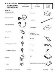
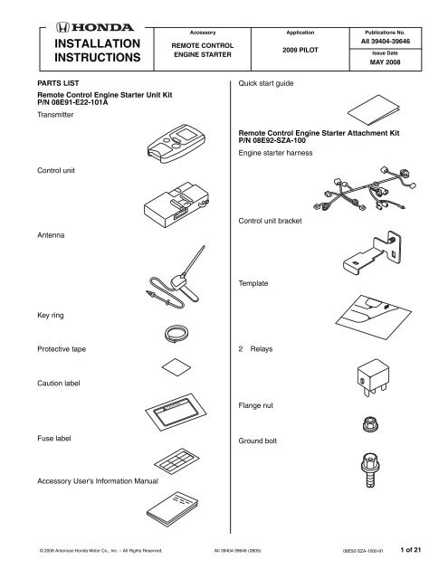
PARTS LIST<br />
<strong>Remote</strong> <strong>Control</strong> <strong>Engine</strong> <strong>Starter</strong> Unit Kit<br />
P/N 08E91-E22-101A<br />
Transmitter<br />
Quick start guide<br />
<strong>Remote</strong> <strong>Control</strong> <strong>Engine</strong> <strong>Starter</strong> Attachment Kit<br />
P/N 08E92-SZA-100<br />
<strong>Engine</strong> starter harness<br />
<strong>Control</strong> unit<br />
<strong>Control</strong> unit bracket<br />
Antenna<br />
Template<br />
Key ring<br />
Protective tape<br />
2 Relays<br />
Caution label<br />
Flange nut<br />
Fuse label<br />
Ground bolt<br />
Accessory User’s Information Manual<br />
© 2008 American Honda Motor Co., Inc. – All Rights Reserved.<br />
AII 39404-39646 (0805)<br />
08E92-SZA-1000-91 1 of 21
16 Wire ties<br />
Illustration of the <strong>Engine</strong> <strong>Starter</strong> Installed on the<br />
Vehicle<br />
ANTENNA<br />
ENGINE STARTER<br />
HARNESS<br />
Long wire tie<br />
5 Urethane tapes<br />
TOOLS AND SUPPLIES REQUIRED<br />
Flat-tip screwdriver<br />
Phillips screwdriver<br />
Small flat-tip screwdriver<br />
Ratchet<br />
8 mm and10 mm Sockets<br />
Combination wrench<br />
Isopropyl alcohol<br />
Shop towel<br />
Tape measure<br />
Scissors<br />
Small rubber mallet<br />
Honda Diagnostic System (HDS)<br />
Masking tape<br />
Needle nose pliers<br />
Plastic trim tool<br />
T/N SILTRIMTL 10<br />
INSTALLATION<br />
NOTE:<br />
CONTROL<br />
UNIT<br />
FUSE CASES<br />
(3A, 3A, 40A)<br />
Customer Information: The information in this<br />
installation instruction is intended for use only by skilled<br />
technicians who have the proper tools, equipment, and<br />
training to correctly and safely add equipment to your<br />
vehicle. These procedures should not be attempted by<br />
“do-it-yourselfers.”<br />
This antenna should only be installed if the ambient<br />
air temperature 15°C (60°F) or above.<br />
1. Make sure you have the anti-theft code for the radio,<br />
then write down the radio station presets.<br />
2. Disconnect the negative cable from the battery.<br />
792001AY<br />
2 of 21 AII 39404-39646 (0805)<br />
© 2008 American Honda Motor Co., Inc. – All Rights Reserved.
Setting the <strong>Control</strong> Unit<br />
3. Touch the metal part of the screwdriver to any metal<br />
part of the vehicle to discharge any static electricity.<br />
CONTROL<br />
UNIT<br />
6. Using isopropyl alcohol on a shop towel, clean the<br />
area where the protective tape will attach. Remove<br />
the adhesive backing from the protective tape, attach<br />
the protective tape to the control unit over the<br />
switches.<br />
CONTROL<br />
UNIT<br />
SMALL<br />
FLAT-TIP<br />
SCREW-<br />
DRIVER<br />
Discharge any<br />
static electricity.<br />
SWITCHES<br />
SWITCHES<br />
SET<br />
PROTECTIVE<br />
TAPE<br />
ADHESIVE<br />
BACKING<br />
SWITCHES<br />
Clean with<br />
isopropyl alcohol.<br />
772505AS<br />
SW:1 RR Junction unit -----------------------> OFF<br />
SW:2 Trunk or Tailgate ----------------------> OFF<br />
SW:3 Smart Entry -----------------------------> OFF<br />
SW:4 Horn or Buzzer Answerback ------> OFF<br />
Removing the Vehicle <strong>Parts</strong><br />
7. Using a plastic trim tool, disengage the eight<br />
retaining tabs and remove left and right lens from the<br />
roof console.<br />
ROOF<br />
CONSOLE<br />
SW:5 Trunk Main SW -------------------------> OFF<br />
SW:6 Reserve ----------------------------------> ON<br />
7D2550AK<br />
4. Check a location of the switches on the control unit.<br />
RIGHT<br />
LENS<br />
NOTE:<br />
• The switches must be selected before the<br />
control unit is plugged in.<br />
• If the switch setting is not correct the remote<br />
engine starter will not operate correctly.<br />
• If you change the switch settings with the unit<br />
connected, you must disconnect the unit then<br />
reconnect it before the settings change.<br />
5. Using a small flat-tip screwdriver, adjust the switches<br />
on the control unit as shown.<br />
LEFT<br />
LENS<br />
4 RETAINING<br />
TABS<br />
4 RETAINING<br />
TABS<br />
PLASTIC TRIM<br />
TOOL<br />
700602BB<br />
© 2008 American Honda Motor Co., Inc. – All Rights Reserved.<br />
AII 39404-39646 (0805)<br />
3 of 21
8. Open the sunglass holder.<br />
11. Flip down the left sunvisor.<br />
VEHICLE<br />
CONNECTOR<br />
HOLDER<br />
FLAT-TIP<br />
SCREWDRIVER<br />
Push and hold the<br />
retaining tab.<br />
ROOF<br />
CONSOLE<br />
SUNGLASS<br />
HOLDER<br />
(Open. )<br />
VANITY<br />
MIRROR<br />
LIGHT<br />
CONNECTOR<br />
Push upward.<br />
Rotate<br />
towards<br />
the door.<br />
LEFT<br />
SUNVISOR<br />
(Turn rearward.)<br />
2 SCREWS<br />
(Black)<br />
2 SCREWS<br />
(Silver)<br />
700603BB<br />
9. Remove the roof console (two black screws, two<br />
silver screws, and unplug the vehicle connectors).<br />
10. Rotate the two sunvisor holders 45°, and remove the<br />
two sunvisor holders.<br />
SUNVISOR<br />
HOLDER<br />
840902AY<br />
12. Locate the slot in the sunvisor holder, and insert a<br />
flat-tip screwdriver into the slot. Push in and hold the<br />
retaining tab.<br />
13. While holding the retaining tab, push up on the left<br />
sunvisor and rotate towards the door to remove the<br />
sunvisor. Unplug the vanity mirror light connector.<br />
If the retaining tab did not stay pushed in, return the<br />
left sunvisor to its original position and repeat steps<br />
11 through 13.<br />
Turn.<br />
2 SUNVISOR<br />
HOLDERS<br />
700215BE<br />
4 of 21 AII 39404-39646 (0805)<br />
© 2008 American Honda Motor Co., Inc. – All Rights Reserved.
14. Using a plastic trim tool, open the lid of the left A-<br />
pillar trim (two retaining tabs).<br />
LEFT<br />
A-PILLAR TRIM<br />
LEFT<br />
A-PILLAR TRIM<br />
LID<br />
2 RETAINING<br />
TABS<br />
18. Shift the select knob to “D” position by pressing down<br />
on the shift lock stopper with the ignition key.<br />
Remove the left side center panel (eight clips and<br />
unplug the vehicle connectors).<br />
LEFT SIDE<br />
CENTER<br />
PANEL<br />
VEHICLE<br />
CONNECTOR<br />
8 CLIPS<br />
BOLT<br />
WEATHERSTRIP<br />
(Release.)<br />
CLIP<br />
15. Remove the bolt from the left A-pillar trim.<br />
16. Remove the weatherstrip and remove the left A-pillar<br />
trim (one clip).<br />
17. Pull off the weatherstrip, remove the left side<br />
dashboard cover (seven retaining tabs).<br />
792203AE<br />
IGNITION KEY<br />
SELECT<br />
KNOB<br />
VEHICLE<br />
CONNECTOR<br />
(If equipped)<br />
792808AE<br />
19. Remove the driver’s dashboard lower cover (12 clips,<br />
one self-tapping screw and unplug the vehicle<br />
connectors). Remove the A/C sensor (two remaining<br />
tabs).<br />
WEATHERSTRIP<br />
(Release.)<br />
12 CLIPS<br />
A/C SENSOR<br />
2 RETAINING<br />
TABS<br />
7 RETAINING<br />
TABS<br />
LEFT SIDE<br />
DASHBOARD<br />
COVER<br />
792403CE<br />
SELF-TAPPING<br />
SCREW<br />
VEHICLE<br />
CONNECTOR<br />
DRIVER’S<br />
DASHBOARD<br />
COVER<br />
A/C SENSOR<br />
792205CE<br />
© 2008 American Honda Motor Co., Inc. – All Rights Reserved.<br />
AII 39404-39646 (0805)<br />
5 of 21
20. Lower the tilt lever and pull the steering wheel out.<br />
4 RETAINING<br />
TABS<br />
UPPER<br />
STEERING<br />
COLUMN<br />
COVER<br />
2 SELF-TAPPING<br />
SCREWS<br />
Routing the <strong>Engine</strong> <strong>Starter</strong> Harness<br />
23. Attach the one 40 A fuse label to the engine starter<br />
harness fuse block.<br />
FUSE LABEL<br />
(3 A)<br />
FUSE LABEL<br />
(40 A)<br />
Push.<br />
TILT LEVER<br />
21. Remove the upper steering column cover:<br />
• Remove the two self-tapping screws.<br />
792404CE<br />
• Push the upper cover inward at the areas shown<br />
to release the four retaining tabs.<br />
22. Remove the lower steering column cover (two selftapping<br />
screws and one screw).<br />
FUSE BLOCK<br />
ENGINE<br />
STARTER<br />
HARNESS<br />
24. Attach the 3 A fuse label to the engine starter<br />
harness fuse block.<br />
840903AY<br />
25. Install the two relays to the engine starter harness<br />
relay blocks.<br />
LOWER<br />
STEERING<br />
COLUMN<br />
COVER<br />
(2) 4- RELAYS<br />
ENGINE<br />
STARTER<br />
HARNESS<br />
RELAY<br />
BLOCK<br />
SCREW<br />
2 SELF-TAPPING<br />
SCREWS<br />
792003BY<br />
792405AE<br />
6 of 21 AII 39404-39646 (0805)<br />
© 2008 American Honda Motor Co., Inc. – All Rights Reserved.
26. Plug the engine starter harness 28-pin connector<br />
into the control unit.<br />
28. Secure the control unit to the vehicle bracket with a<br />
6 mm flange nut.<br />
STEERING<br />
WHEEL<br />
28-PIN<br />
CONNNECTOR<br />
CONTROL<br />
UNIT<br />
STEERING<br />
SHAFT<br />
ENGINE<br />
STARTER<br />
HARNESS<br />
792004AY<br />
27. Install the control unit bracket to the control unit.<br />
VEHICLE<br />
BRACKET<br />
Hold against<br />
the brackets.<br />
CONTROL<br />
UNIT<br />
CONTROL<br />
UNIT<br />
BRACKET<br />
CONTROL<br />
UNIT<br />
BRACKET<br />
CONTROL<br />
UNIT<br />
VEHICLE<br />
BRACKET<br />
FLANGE NUT,<br />
6 mm<br />
CONTROL<br />
UNIT<br />
STEERING<br />
SHAFT<br />
792401CY<br />
792005AY<br />
© 2008 American Honda Motor Co., Inc. – All Rights Reserved.<br />
AII 39404-39646 (0805)<br />
7 of 21
29. Install the engine starter harness fuse block clip on<br />
the control unit bracket.<br />
31. Route the engine starter harness relay block to the<br />
right side of the vehicle.<br />
ENGINE<br />
STARTER<br />
HARNESS<br />
VEHICLE<br />
RELAY BLOCK<br />
CLIP<br />
FUSE BLOCK<br />
CONTROL<br />
UNIT<br />
BRACKET<br />
792402AY<br />
ENGINE<br />
STARTER<br />
HARNESS<br />
RELAY<br />
BLOCK<br />
792404AY<br />
30. Install the engine starter harness clip on the vehicle<br />
bracket.<br />
ENGINE<br />
STARTER<br />
HARNESS<br />
32. Install the engine starter harness relay block on the<br />
vehicle relay block.<br />
33. Remove the blue tape from the vehicle 4-pin<br />
connector . Plug the engine starter harness 4-pin<br />
connector to the vehicle 4-pin connector.<br />
STEERING<br />
WHEEL<br />
VEHICLE<br />
4-PIN<br />
CONNECTOR<br />
(WHITE)<br />
CLIP<br />
VEHICLE<br />
BRACKET<br />
792403AY<br />
ENGINE<br />
STARTER<br />
HARNESS<br />
BLUE TAPE<br />
(Remove.)<br />
4-PIN CONNECTOR<br />
792501AY<br />
8 of 21 AII 39404-39646 (0805)<br />
© 2008 American Honda Motor Co., Inc. – All Rights Reserved.
34. Secure the 4-pin connector to the vehicle harness<br />
with one wire tie.<br />
36. Locate and remove the blue tape from the vehicle 2-<br />
pin connectors (white), and unplug the vehicle 2-pin<br />
connectors as shown.<br />
WIRE TIE<br />
FUSE BOX<br />
VEHICLE 2-PIN<br />
CONNECTORS<br />
(WHITE)<br />
VEHICLE<br />
HARNESS<br />
BLUE<br />
TAPE<br />
4-PIN CONNECTORS<br />
792502AY<br />
35. Align the green-taped part of the engine starter<br />
harness with the vehicle clip. Secure the engine<br />
starter harness to the vehicle harness with one wire<br />
tie.<br />
STEERING<br />
SHAFT<br />
7D0701BE<br />
37. Plug the engine starter harness 2-pin connectors to<br />
the vehicle 2-pin connectors as shown.<br />
WIRE TIE<br />
VEHICLE<br />
HARNESS<br />
ENGINE<br />
STARTER<br />
HARNESS<br />
FUSE<br />
BOX<br />
VEHICLE<br />
2-PIN<br />
CONNECTORS<br />
2-PIN<br />
CONNECTORS<br />
FUSE<br />
BOX<br />
VEHICLE<br />
CLIP<br />
GREEN<br />
TAPE<br />
792503BY<br />
ENGINE STARTER<br />
HARNESS<br />
STEERING<br />
SHAFT<br />
792706BY<br />
38. Route the engine starter harness 2-pin connectors<br />
behind the fuse box as shown.<br />
© 2008 American Honda Motor Co., Inc. – All Rights Reserved.<br />
AII 39404-39646 (0805)<br />
9 of 21
39. Secure the 2-pin connectors to the vehicle harness<br />
with one wire tie.<br />
42. Route the engine starter harness ground terminal as<br />
shown.<br />
FUSE<br />
BOX<br />
ENGINE STARTER<br />
HARNESS<br />
PARKING<br />
BRAKE<br />
LEVER<br />
ENGINE STARTER<br />
HARNESS GROUND<br />
TERMINAL<br />
VEHICLE<br />
HARNESS<br />
WIRE TIE<br />
2-PIN<br />
CONNECTORS<br />
STEERING<br />
SHAFT<br />
792707EY<br />
40. Cut the urethane tape into two equal parts, and cut<br />
one half of the urethane tape to the dimension<br />
shown.<br />
PARKING BRAKE<br />
LEVER<br />
VEHICLE<br />
BOLT<br />
(Discard.)<br />
GROUND<br />
BOLT<br />
FUSE<br />
BOX<br />
43. Remove and discard the vehicle bolt near the<br />
parking brake lever, install the engine starter<br />
harness ground terminal with the ground bolt<br />
including the kit.<br />
792708BY<br />
44. Loosely secure the engine starter harness to the<br />
vehicle harness with two wire ties.<br />
2 WIRE TIES<br />
(Loosely secure.)<br />
10 mm<br />
URETHANE<br />
TAPE<br />
URETHANE<br />
TAPE<br />
VEHICLE<br />
BRACKET<br />
7D2401AB<br />
41. Clean the vehicle bracket surface where the<br />
urethane tape will attach with isopropyl alcohol.<br />
Attach the urethane tape that you cut in step 40 to<br />
the vehicle bracket as shown.<br />
ENGINE<br />
STARTER<br />
HARNESS<br />
VEHICLE<br />
HARNESS<br />
792709BY<br />
10 of 21 AII 39404-39646 (0805)<br />
© 2008 American Honda Motor Co., Inc. – All Rights Reserved.
45. Route the engine starter harness 5-pin connector to<br />
the ignition switch.<br />
IGNITION<br />
SWITCH<br />
47. Unplug the vehicle 8-pin connector, and plug it into<br />
the engine starter harness 8-pin connectors. Plug<br />
the remaining engine starter harness 8-pin<br />
connector into the wiper switch.<br />
5-PIN<br />
CONNECTOR<br />
8-PIN<br />
CONNECTORS<br />
VEHICLE<br />
8-PIN<br />
CONNECTOR<br />
ENGINE<br />
STARTER<br />
HARNESS<br />
792601BY<br />
BODY<br />
SWITCH<br />
ENGINE<br />
STARTER<br />
HARNESS<br />
WIPER<br />
SWITCH<br />
792702AY<br />
48. Route the engine starter harness into the harness<br />
case.<br />
46. Unplug the vehicle 12-pin connector, and plug it into<br />
the engine starter harness 12-pin connectors. Plug<br />
the remaining engine starter harness 12-pin<br />
connector into the turn signal switch.<br />
HARNESS<br />
CASE<br />
VEHICLE<br />
12-PIN<br />
CONNECTOR<br />
12-PIN<br />
CONNECTORS<br />
ENGINE<br />
STARTER<br />
HARNESS<br />
TURN<br />
SIGNAL<br />
SWITCH<br />
FRONT<br />
ENGINE<br />
STARTER<br />
HARNESS<br />
792703AY<br />
BODY<br />
SWITCH<br />
792701AY<br />
© 2008 American Honda Motor Co., Inc. – All Rights Reserved.<br />
AII 39404-39646 (0804)<br />
11 of 21
49. Secure the 12-pin and 8-pin connectors to the<br />
harness case with two wire ties.<br />
HARNESS<br />
CASE<br />
12-PIN<br />
CONNECTORS<br />
50. Unplug the vehicle 5-pin connector from the ignition<br />
switch, and plug the engine starter harness 5-pin<br />
connector into the ignition switch.<br />
Connector unlock<br />
2<br />
Pull.<br />
1<br />
Push.<br />
Connector lock<br />
Push.<br />
2<br />
3<br />
1<br />
5-PIN<br />
CONNECTOR<br />
FRONT<br />
8-PIN<br />
CONNECTORS<br />
ENGINE<br />
STARTER<br />
HARNESS<br />
2 WIRE TIES<br />
792704BY<br />
VEHICLE<br />
5-PIN<br />
CONNECTOR<br />
5-PIN<br />
CONNECTOR<br />
ENGINE<br />
STARTER<br />
HARNESS<br />
URETHANE<br />
TAPE<br />
5-PIN<br />
CONNECTOR<br />
792602CY<br />
51. Plug the engine starter harness 5-pin connector into<br />
the vehicle 5-pin connector.<br />
NOTE: Check that the engine starter harness 5-pin<br />
connector is connected to the vehicle connector and<br />
locked securely. A loosely connected can cause engine to<br />
stall during driving.<br />
52. Wrap one urethane tape around the joint 5-pin<br />
connector.<br />
12 of 21 AII 39404-39646 (0805)<br />
© 2008 American Honda Motor Co., Inc. – All Rights Reserved.
53. Secure the joint of the engine starter harness 5-pin<br />
connector and vehicle 5-pin connector to the<br />
between the vehicle harness and the engine starter<br />
harness with one long wire tie.<br />
55. Secure the engine starter harness to the vehicle<br />
harness with one wire tie as shown.<br />
IGNITION SWITCH<br />
ENGINE<br />
STARTER<br />
HARNESS<br />
VEHICLE<br />
HARNESS<br />
LONG<br />
WIRE TIE<br />
5-PIN<br />
CONNECTOR<br />
<br />
VEHICLE<br />
HARNESS<br />
ENGINE<br />
STARTER<br />
HARNESS<br />
WIRE<br />
TIE<br />
792705CY<br />
LONG<br />
WIRE TIE<br />
VEHICLE<br />
HARNESS<br />
5-PIN<br />
CONNECTOR<br />
792603DY<br />
54. Unplug the vehicle 7-pin connector from the ignition<br />
switch, and plug the engine starter harness 7-pin<br />
connectors to the ignition switch and vehicle 7-pin<br />
connector.<br />
Antenna Installation<br />
56. Bend the antenna plate according to the full scale<br />
drawing shown.You can easily work two needle nose<br />
piliers as shown<br />
VEHICLE<br />
7-PIN<br />
CONNECTOR<br />
IGNITION<br />
SWITCH<br />
ANTENNA<br />
13 mm<br />
8 mm<br />
PLATE<br />
NEEDLE NOSE<br />
PLIERS<br />
7-PIN<br />
CONNECTOR<br />
ENGINE<br />
STARTER<br />
HARNESS<br />
7-PIN<br />
CONNECTOR<br />
792604DY<br />
SCALE<br />
792710AY<br />
© 2008 American Honda Motor Co., Inc. – All Rights Reserved.<br />
AII 39404-39646 (0805)<br />
13 of 21
57. Starting near the antenna end of the cable, wrap<br />
three urethane tapes around the antenna cable at<br />
the measurements shown.<br />
59. Secure the template to the windshield with masking<br />
tapes by aligning it with the edge of the black ceramic<br />
paint as shown.<br />
ANTENNA<br />
CABLE<br />
ANTENNA<br />
BLACK<br />
CERAMIC<br />
PAINT<br />
410 mm<br />
40 mm<br />
URETHANE<br />
TAPE<br />
40<br />
mm<br />
FRONT<br />
WINDOW<br />
701015AB<br />
MIRROR<br />
TEMPLATE<br />
MASKING<br />
TAPES<br />
6N3002AK<br />
58. Using scissors, cut out the template.<br />
60. Using isopropyl alcohol on a shop towel, clean the<br />
area where the antenna will attach. Allow to dry<br />
before proceeding.<br />
Cut out.<br />
TEMPLATE<br />
Cut out.<br />
HEADLINER<br />
TEMPLATE<br />
7209041K<br />
PLATE<br />
ANTENNA<br />
ADHESIVE<br />
BACKING<br />
6N3004BK<br />
61. Remove the adhesive backing from the antenna,<br />
insert the antenna plate under the headliner, and<br />
attach the antenna to the windshield aligning the<br />
template.<br />
62. Remove the template.<br />
14 of 21 AII 39404-39646 (0805)<br />
© 2008 American Honda Motor Co., Inc. – All Rights Reserved.
63. Route the antenna cable to the left side of the<br />
vehicle, and push it into the headliner as shown. Be<br />
careful not to crease the headliner.<br />
HEADLINER<br />
65. Clean the vehicle panel surface where the urethane<br />
tape will attach with isopropyl alcohol. Secure the<br />
antenna cable to the vehicle panel with the<br />
remaining part of the urethane tape you cut in step<br />
40. Be careful no to crease the headliner.<br />
Remains of urethane tape<br />
cut in step 40.<br />
HEADLINER<br />
VEHICLE<br />
PANEL<br />
ANTENNA<br />
CABLE<br />
6N30050K<br />
ANTENNA<br />
CABLE<br />
URETHANE<br />
TAPE<br />
64. Clean the vehicle panel surface where the urethane<br />
tape will attach with isopropyl alcohol. Secure the<br />
antenna cable to the vehicle panel with the smaller<br />
part urethane tape that you cut into two in step 40.<br />
Be careful not to crease the headliner.<br />
701017BB<br />
66. Route the antenna cable along the left A-pillar and<br />
secure the antenna cable to the vehicle harness with<br />
four wire ties as shown.<br />
VEHICLE<br />
PANEL<br />
ANTENNA<br />
CABLE<br />
ANTENNA<br />
CABLE<br />
HEADLINER<br />
1/2 of urethane<br />
tape cut in step 40.<br />
URETHANE TAPE<br />
VEHICLE<br />
HARNESS<br />
4 WIRE TIES<br />
LEFT<br />
A-PILLAR<br />
701016BB<br />
792711AY<br />
© 2008 American Honda Motor Co., Inc. – All Rights Reserved.<br />
AII 39404-39646 (0805)<br />
15 of 21
67. Secure the antenna cable to the vehicle harness with<br />
one wire tie.<br />
69. Route the antenna cable terminal to right side of the<br />
vehicle, and plug it to the control unit as shown.<br />
VEHICLE<br />
HARNESS<br />
ANTENNA<br />
CABLE<br />
ANTENNA<br />
CABLE<br />
ANTENNA<br />
CABLE<br />
TERMINAL<br />
WIRE TIE<br />
DRIVER’S<br />
DASHBOARD<br />
COVER<br />
OPENING<br />
700101AY<br />
68. Route the antenna cable along the engine starter<br />
harness. Secure the antenna cable to the vehicle<br />
harness with the two wire ties that loosely secure the<br />
engine starter harness in step 44.<br />
CONTROL<br />
UNIT<br />
700103AY<br />
ANTENNA<br />
CABLE<br />
70. Secure the engine starter harness and antenna<br />
cable with one wire tie as shown.<br />
2 WIRE TIES<br />
2 WIRE TIES ANTENNA CABLE<br />
(Bundle the excess.)<br />
FUSE<br />
BOX<br />
VEHICLE<br />
HARNESS<br />
700102BY<br />
ENGINE<br />
STARTER<br />
HARNESS<br />
ANTENNA<br />
CABLE<br />
WIRE TIE<br />
700104AY<br />
71. Bundle the excess of the antenna cable. Secure the<br />
antenna cable to the engine starter harness with two<br />
wire ties.<br />
16 of 21 AII 39404-39646 (0805)<br />
© 2008 American Honda Motor Co., Inc. – All Rights Reserved.
72. Using isopropyl on a shop towel, clean the hood<br />
where the caution label will attach.<br />
REMOTE ENGINE STARTER REGISTRATION<br />
1. Acquire the PCM Code from the Interactive Network.<br />
HOOD<br />
CAR ICON<br />
CAUTION<br />
LABEL<br />
ADHESIVE<br />
BACKING<br />
73. Attach the caution label to the hood in the area<br />
shown.<br />
74. Check that all wire harnesses and cables are routed<br />
properly and that all connectors are plugged in.<br />
75. Reinstall all removed parts. Check that all clips and<br />
other fasteners are installed securely. Take care not<br />
to pinch the side curtain airbag with the clip during<br />
reinstallation of the left front A-pillar trim. Do not<br />
push the front pillar trim excessively.<br />
76. Reconnect the negative cable to the battery.<br />
Check that the electrical accessory and other<br />
electrical systems function properly.<br />
77. Enter the customer’s radio anti-theft code and reset<br />
the radio station presets.<br />
78. Reset the clock on models without navigation.<br />
79. Do the “REMOTE ENGINE STARTER<br />
REGISTRATION” and “FUNCTION CHECK.”<br />
7D0702AE<br />
2. Connect the HDS tester to the OBD II data link<br />
connector, then turn the ignition switch to the ON (II).<br />
3. Start the HDS, and click the car icon.<br />
792901AH<br />
4. Input the VIN and other required information into the<br />
HDS, then click the check button.<br />
Input the VIN and other<br />
required information.<br />
CHECK BUTTON<br />
752502AS<br />
5. Select the Honda Systems, then click the check<br />
button.<br />
© 2008 American Honda Motor Co., Inc. – All Rights Reserved.<br />
AII 39404-39646 (0805)<br />
17 of 21
A “REMARKS” message.<br />
Select<br />
“Honda Systems.”<br />
CHECK BUTTON<br />
752503AS<br />
CHECK BUTTON<br />
752505AS<br />
6. Select the R/C ENG STARTER and click the check<br />
button.<br />
8. Select REGISTER REMOTE CONTROL ENGINE<br />
STARTER UNIT, then click the check button.<br />
Select<br />
“R/C ENG STARTER.”<br />
CHECK BUTTON<br />
752504AS<br />
7. A REMARKS massage will display. Click on the<br />
check button.<br />
Select<br />
“REGISTER REMOTE CONTROL<br />
ENGINE STARTER UNIT.”<br />
CHECK BUTTON<br />
752506AS<br />
9. The following message will display: Obtain PCMcode<br />
(IMMOBILIZER PCM CODE) from iN. This<br />
18 of 21 AII 39404-39646 (0805)<br />
© 2008 American Honda Motor Co., Inc. – All Rights Reserved.
vehicle’s VIN will be required to obtain the<br />
password. (USA). Click on the check button.<br />
“The registration of the <strong>Remote</strong> <strong>Control</strong><br />
<strong>Engine</strong> <strong>Starter</strong> Unit has been completed”.<br />
“Obtain PCM-code” message.<br />
CHECK BUTTON<br />
CHECK BUTTON<br />
752507AS<br />
10. Input the PCM Code, then click the check button.<br />
NOTE: To ensure security, the PCM code (password)<br />
is changed everyday, so it is impossible to register<br />
the remote control engine starter if the dates of the<br />
PCM code acquisition and registration are different.<br />
The date of the HDS tester should also be the same.<br />
752510AS<br />
12. The following message will display: Check that the<br />
engine can be started by the Transmitter. is<br />
shown, then click on the check button.<br />
“Check that the engine can be started by<br />
the Transmitter”.<br />
Input the PCM Code.<br />
CHECK BUTTON<br />
752511AS<br />
CHECK BUTTON<br />
13. Perform the function test on the next page then<br />
disconnect the HDS.<br />
752509AS<br />
11. The following message will display: The registration<br />
of the <strong>Remote</strong> <strong>Control</strong> <strong>Engine</strong> <strong>Starter</strong> Unit has<br />
been completed. Click on the check button.<br />
© 2008 American Honda Motor Co., Inc. – All Rights Reserved.<br />
AII 39404-39646 (0805)<br />
19 of 21
FUNCTION CHECK<br />
Operating Conditions<br />
• Hood is closed<br />
• Shift lever in park<br />
• The key is out of the ignition<br />
• All doors and tailgate closed and locked<br />
Inspection<br />
1. Within 1 second, press the command button, and then the start button on the transmitter.<br />
The engine should start if all operating conditions are met.<br />
Does the engine start<br />
Yes - Operation is normal.<br />
No:<br />
• Make sure all “Operating Conditions” are met.<br />
• Check the engine starter harness connections.<br />
• Connect the HDS and check for an indicated failure.<br />
(Refer to the appropriate service manual for details.)<br />
2. Press the command button on the transmitter, and within 1 second,<br />
press the stop button. The engine should stop.<br />
Does the engine stop<br />
Yes - Operation is normal.<br />
No - Check the engine starter harness connections.<br />
3. After the engine has stopped, start the engine again, and check that<br />
the engine stops after each of the following conditions:<br />
STOP<br />
BUTTON<br />
TRANSMITTER<br />
DISPLAY<br />
COMMAND<br />
BUTTON<br />
START<br />
BUTTON<br />
732904AY<br />
NOTE:<br />
• After each test the ignition key must be cycled, or the driver’s door must be opened and closed.<br />
• Move the shift lever out of the P position.<br />
• Unlock or open the doors or the tailgate.<br />
• Open the hood.<br />
• Insert the key in the ignition.<br />
• Press on the brake pedal.<br />
Does the engine stop after each of these tests<br />
Yes - Operation is normal.<br />
No - Check the engine starter harness connections.<br />
4. Check that the power window or the moon roof does not function when the engine is started with the transmitter.<br />
5. Press the command button on the transmitter two times and check the vehicle condition on the display.<br />
20 of 21 AII 39404-39646 (0805)<br />
© 2008 American Honda Motor Co., Inc. – All Rights Reserved.
6. Check the operation of the transmitter when the<br />
vehicle is 100 m to 150 m (325 to 490 ft.) away, and<br />
in direct sight.<br />
How to Program an Additional Transmitter<br />
1. Connect the HDS to the data link connector.<br />
2. Start the HDS and click on the car icon.<br />
3. Input the vehicle’s VIN and other required<br />
information.<br />
4. Select Honda Systems.<br />
5. Select R/C <strong>Engine</strong> <strong>Starter</strong>.<br />
6. Select REGISTER NEW TRANSMITTER.<br />
7. When “Ready to program the new transmitter”<br />
shows, select ENTER.<br />
8. Press and release the Command button.<br />
9. Press and release the Stop button.<br />
10. Perform the function check on both transmitters.<br />
NOTE: Only 2 remotes can be stored in the system’s<br />
memory.<br />
© 2008 American Honda Motor Co., Inc. – All Rights Reserved.<br />
AII 39404-39646 (0805)<br />
21 of 21