group 9 Ignition System.pdf
group 9 Ignition System.pdf
group 9 Ignition System.pdf

Create successful ePaper yourself
Turn your PDF publications into a flip-book with our unique Google optimized e-Paper software.
9-<br />
PART 9-1<br />
PAGE<br />
General <strong>Ignition</strong> Service 9-1<br />
PART 9-2<br />
Loadomatic Distributors 9-25<br />
PART 9.3<br />
Dual Advance Distributors 9-29<br />
PART 9-4<br />
PAGE<br />
Centrifugal Advance<br />
Distributors 9-37<br />
PART 9-5<br />
Specifications 9-43<br />
9-1-<br />
Section<br />
Page<br />
1 Diagnosis and Testing 9-1<br />
General Information 9-1<br />
<strong>Ignition</strong> <strong>System</strong> Tests-Conventional<br />
Test Equipment 9-3<br />
<strong>Ignition</strong> <strong>System</strong> Tests-Rotunda<br />
Oscilloscope Testers 9-6<br />
Distributor Checks 9-15<br />
Distributor Tests-Rotunda ARE-27-44<br />
Dwell Tester ~ ,9-16<br />
Distributor Tests-Rotunda ARE-236<br />
Distributor Tester 9-16<br />
Distributor Tests-Rotunda ARE-j4-16<br />
Distributor Tester 9-16<br />
Section<br />
Page<br />
2 Common Adjustments and Repairs<br />
Breaker Points and Condenser<br />
9-19<br />
9-19<br />
I gmtlon .. T lmmg .. 920 -<br />
Spark Plug Wire Replacement 9-21<br />
Spark Plugs , 9-22<br />
Resistance Wire Replacement 9-22<br />
3 Cleaning and Inspection 9-23<br />
Spark Plugs 9-23<br />
Distributors 9-23<br />
Secondary Wiring 9-24<br />
Coil... ... 9-24<br />
Distributor Cap 9-24<br />
Rotor 9-24<br />
This part covers ignition system<br />
description and operation, general<br />
ignition system diagnosis, tests, adjustments<br />
and repair operations, In<br />
addition, the cleaning and inspection<br />
procedures are covered.<br />
For distributor removal, disassembly,<br />
assembly, installation, major repair<br />
procedures and specifications,<br />
refer to the pertinent part of this<br />
<strong>group</strong>.<br />
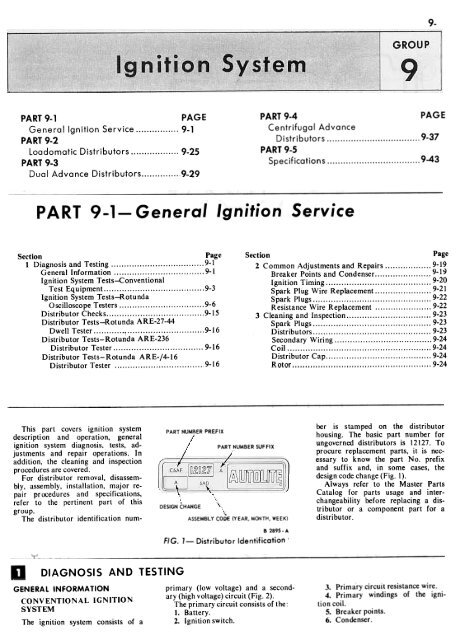
The distributor identification num-<br />
PART NUMBER PREFIX<br />
A<br />
PART NUMBER SUFFIX<br />
DES.lGN CHANGE \<br />
"-<br />
ASSEMBLY CODE (YEAR, MONTH,WEEK)<br />
B 2895-A<br />
FIG. 1- Distributor Identification'<br />
ber is stamped on the distributor<br />
housing. The basic part number for<br />
ungoverned distributors is 12127. To<br />
procure replacement parts, it is necessary<br />
to know the part No. prefix<br />
and suffix and, in some cases, the<br />
design code change (Fig. I).<br />
Always refer to the Master Parts<br />
Catalog for parts usage and interchangeability<br />
before replacing a distributor<br />
or a component part for a<br />
distributor.<br />
DIAGNOSIS AND TESTING<br />
GENERAL INFORMATION<br />
primary (low voltage) and a second-<br />
CONVENTIONAL IGNITION ary (high.voltage) cir.cuit (F.ig. 2).<br />
SYSTEM The primary circuit consists of the:<br />
I. Battery.<br />
The ignition system consists of a 2. <strong>Ignition</strong> switch.<br />
3. Primary circuit resistance wire.<br />
4. Primary windings of the ignition<br />
coil.<br />
5. Breaker points.<br />
6. Condenser.
The secondary circuit consists of<br />
the:<br />
I. Secondary windings of the ignition<br />
coil.<br />
2. Distributor rotor.<br />
3. Distributor cap.<br />
4. High tension wires.<br />
5. Spark plugs.<br />
IGNITION<br />
When the breaker points are<br />
closed, the primary or low voltage<br />
current flows from the battery<br />
through the ignition switch to the<br />
primary windings in the coil, then to<br />
ground through the closed breaker<br />
points. When the breaker points<br />
open, the magnetic field built up in<br />
Red-G,een<br />
the primary windings of the coil<br />
moves through the secondary windings<br />
of the coil producing high voltage<br />
current. High voltage current is<br />
produced each time the breaker<br />
points open. The high voltage flows<br />
through the coil high tension lead to<br />
the distributor cap where the rotor<br />
distributes it to one of the spark plug<br />
terminals in the distributor cap. This<br />
process is repeated for every power<br />
stroke of the engine.<br />
TRANSISTOR<br />
SYSTEM<br />
IGNITION<br />
The permatuned transistor ignition<br />
system is standard on 427 engines.<br />
Fig. 3 shows a schematic of the transistor<br />
ignition system.<br />
The ignition coil primary in the<br />
transistor system is designed to draw<br />
12 amperes peak current, or approximately<br />
5.5 amperes average current<br />
as indicated on a conventional ammeter,<br />
in order to provide high spark<br />
plug voltage at the higher engine<br />
speeds.<br />
The transistor in the system acts<br />
as a heavy duty switch or relay. It is<br />
similar in action to a horn relay, except<br />
that it has no moving parts,<br />
and thus acts with very little time<br />
lag. The transistor is connected between<br />
the battery and the coil, and<br />
is used to make and break the coil<br />
primary circuit.
~<br />
B1844-B<br />
into the circuit. Do not connect a<br />
tachometcr or dwell meter into the<br />
circuit in any other manner. or readings<br />
will be inaccurate and damage<br />
may occur to the transistor. or<br />
change its operating characteristics.<br />
Connect the tachometer red lead<br />
to the tachometer block red (small)<br />
terminal and black lead to the black<br />
(large) terminal.<br />
IGNITION SYSTEM TESTS<br />
CONVENTIONAL TEST<br />
EQUIPMENT<br />
FIG. 4-Amplifier Assembly CONVENTIONAL IGNITION<br />
SYSTEM<br />
The distributor controls the transistor.<br />
The 7.l-7.9-ohm resistor, connected<br />
between the distributor and<br />
Trouble Isolation<br />
the transistor (in the wiring harness),<br />
limits the transistor control current<br />
(and distributor point current) to<br />
0.5 ampere. The low distrib4lor<br />
point current eliminates pitting and<br />
gives long distributor point life.<br />
The amplifier assembly (Fig. 4) is<br />
mounted under the instrument panel<br />
to protect the parts from engine<br />
heat.<br />
A ceramic ballast resistor block<br />
and a tachometer connector block<br />
are mounted in the engine compartment.<br />
A 2-ampere fuse between the<br />
black (large) terminal of the tach<br />
block and the coil primary circuit<br />
prevents the transistor from being<br />
damaged by the application of external<br />
devices other than normal<br />
testing equipment.<br />
The tachometer block is used to<br />
connect a tachometer or dwell meter<br />
,~"<br />
<strong>Ignition</strong> system troubles are<br />
caused by a failure in the primary<br />
and/or the secondary circuit or incorrect<br />
ignition timing. If an engine<br />
trouble has been traced to the ignition<br />
system from the Engine<br />
Trouble Diagnosis Guide, the trouble<br />
can be found by performing an<br />
ignition system test on a scope or by<br />
further isolating the trouble to the<br />
primary or secondary circuit as<br />
follows:<br />
1. Disconnect the brown wire<br />
from the starter relay I terminal<br />
and the red and blue wire from the<br />
starter relay S terminal.<br />
2. Remove the coil high tension<br />
lead from the distributor cap.<br />
3. Turn on the ignition switch.<br />
4. While holding the high tension<br />
lead approximately 3/16 inch from the<br />
cylinder head or any other good<br />
ground, crank the engine by using<br />
an auxiliary starter switch between<br />
the starter relay battery and S terminals.<br />
If the spark is good, the trouble<br />
lies in the secondary circuit.<br />
If there is no spark or a weak<br />
spark, the trouble is in the primary<br />
circuit, coil to distributor high tension<br />
lead, or the coil.<br />
Primary Circuit. A breakdown or<br />
energy loss in the primary circuit<br />
can be caused by:<br />
I. Defective primary wiring, or<br />
loose or corroded terminals.<br />
2. Burned, shorted, sticking or<br />
improperly adjusted breaker points.<br />
3. A defective coil.<br />
4. A defective condenser.<br />
To isolate a trouble in the primary<br />
circuit, proceed as follows:<br />
Turn the ignition switch off and<br />
remove the auxiliary starter switch<br />
from the starter relay.<br />
Install the coil high tension lead<br />
in the distributor cap, the red and<br />
blue wire on the starter relay S<br />
terminal and the brown wire on the<br />
starter relay I terminal.<br />
Now perform a primary circuit<br />
test.<br />
Secondary Circuit. A breakdown<br />
or energy loss in the secondary circuit<br />
can be caused by:<br />
I. Fouled or improperly adjusted<br />
spark plugs.<br />
2. Defective high tension wiring.<br />
3. High tension leakage across the<br />
coil, distributor cap or rotor resulting<br />
from an accumulation of dirt.<br />
To isolate a trouble in the ~econdary<br />
circuit, proceed as follows:<br />
Turn the ignition switch off and<br />
remove the auxiliary starter switch<br />
=',<br />
rl<br />
Red<br />
TO<br />
DISTRIBUTOR<br />
HOUSING<br />
I~, ...<br />
Black<br />
D<br />
82000. C<br />
FIG. 5-B_attery to Coil and Starting<br />
<strong>Ignition</strong> Circuit Tes,'<br />
82002- C B2004-C<br />
Resistance Wire Test<br />
FIG. 6-lgnition Switch Test FIG. 7-
9-4 GROUP 9-lgnition <strong>System</strong><br />
from the starter relay.<br />
Install the coil high tension lead in<br />
the distributor cap, the red and blue<br />
wire on the starter relay S terminal<br />
and the brown wire on the starter<br />
relay I terminal.<br />
Now perform a secondary circuit<br />
test.<br />
Primary Circuit Tests<br />
A complete test of the primary<br />
circuit consists of checking the circuit<br />
from the battery to the coil, the<br />
circuit from the coil to ground, and<br />
the starting ignition circuit.<br />
Excessive voltage drop in the primary<br />
circuit will reduce the<br />
secondary output of the ignition coil,<br />
resulting in hard starting and poor<br />
performa nce.<br />
Battery to Coil Test<br />
I. Connect the voltmeter reads as<br />
shown in Fig. 5.<br />
2. Install a jumper wire from the<br />
distributor terminal of the coil to a<br />
good ground on the distributor<br />
housing.<br />
3. Turn the lights and accessories<br />
off.<br />
4. Turn the ignition switch on.<br />
5. If the voltmeter reading is<br />
between 4.5 and 6.9 volts, the primary<br />
circuit from the battery to the coil is<br />
satisfactory.<br />
6. If the voltmeter reading is<br />
greater than 6.9 volts, check the following:<br />
The battery and cables for loose<br />
connections or corrosion.<br />
The primary wiring for worn insulation,<br />
broken strands, and loose<br />
or corroded terminals.<br />
The resistance wire for defects.<br />
The starter relay to ignition switch<br />
for defects.<br />
If the voltmeter reading is less<br />
than 4.5 volts the resistance wire<br />
should be replaced.<br />
Starting <strong>Ignition</strong> Circuit Test<br />
1. ,Connect the voltmeter leads as<br />
shown in Fig. 5.<br />
2. Disconnect and ground the coil<br />
to distributor high tension lead at the<br />
distributor.<br />
3. With the ignition switch off,<br />
crank the engine by installing a<br />
jumper wire between the battery and<br />
the S terminal of the starter relay<br />
while observing the voltage drop.<br />
4. If the voltage drop is 0.1 volt<br />
or less, the starting ignition circuit is<br />
satisfactory.<br />
5. If the voltage drop is greater<br />
than 0.1 volt, clean and tighten the<br />
termin~ls in the circuit or replaoe<br />
the wiring as necessary.<br />
<strong>Ignition</strong> Switch Test<br />
I. Connect the voltmeter leads as<br />
shown in Fig. 6.<br />
2. Install a jumper wire from the<br />
distributor terminal of the coil to a<br />
good ground on the distributor body.<br />
3. Turn all of the accessories and<br />
lights off.<br />
4. Turn the ignition switch on.<br />
5. If the voltmeter reading is 0.3<br />
volt or less, the ignition switch and<br />
the relay to switch wire are satisfactory.<br />
6. If the voltmeter reading is<br />
greater than 0.3 volt, either the ignition<br />
switch and/or the wire are defective.<br />
Resistance Wire Test<br />
I. Connect the voltmeter leads as<br />
shown in Fig. 7.<br />
2. Install a jumper wire from the<br />
distributor terminal of the coil to a<br />
good ground on the distributor housing.<br />
3. Turn all of the accessories and<br />
lights off.<br />
4. Turn the ignition switch on.<br />
5. If the voltmeter reading is between<br />
6.6 and 4.5 volts the resistance<br />
wire is satisfactory.<br />
6. If the voltmeter reading is<br />
greater thant 6.6 volts, or less than<br />
4.5 replace the resistance wire.<br />
7. Turn the ignition switch off.<br />
Disconnect the voltmeter leads. Remove<br />
the jumper wire connected to<br />
the coil DIST terminal and the distributor.<br />
Remove the jumper wire<br />
connected to the coil BAT terminal<br />
and the coil BAT lead. Connect the<br />
BA T lead to the BAT terminal and go<br />
on to the Coil to Ground Test.<br />
Coil To Ground Test<br />
I. Connect the voltmeter leads as<br />
shown in Fig. 8.<br />
2. Close the breaker points.<br />
3. Turn all lights and accessories<br />
off.<br />
4. Turn the ignition switch on.<br />
5. If the voltmeter reading is 0.1<br />
volt or less, the primary circuit from<br />
coil to ground is satisfactory.<br />
6. If the voltmeter reading is<br />
greater than o. I volt, test the voltage<br />
drop between each of the following:<br />
The coil and the breaker point connections<br />
of the coil to distributor primary<br />
wire.<br />
The movable breaker point and<br />
the breaker plate.<br />
The breaker plate and the distributor<br />
housing.<br />
The distributor housing and engine<br />
ground.<br />
Rotundo RE.I6-31 or<br />
RE.27.44 Tester-=<br />
Rp-i<br />
FIG. 8-Coil<br />
'Slack<br />
to Ground Test<br />
82008- C<br />
7. Turn the ignition switch off.<br />
Disconnect the voltmeter leads. Remove<br />
the jumper wire connected to the<br />
coil DIST terminal and the distributor<br />
primary wire. Connect the distributor<br />
primary wire to the DIST<br />
terminal of the coil.<br />
Breaker Points. Clean and inspect<br />
the breaker points by following the<br />
procedure under Cleaning and Inspection<br />
(Section 3 of this part).<br />
The breaker point dwell can be<br />
checked with a distributor tester or<br />
a dwell meter by following the procedure<br />
under Distributor Tests in<br />
this section of the manual.<br />
The breaker point resistance can<br />
be checked with a Rotunda ARE-1416<br />
distributor tester by following the<br />
procedure under Distributor Tests<br />
in this section of the manual.<br />
Coil. Clean and inspect the coil by<br />
following the procedure under<br />
Cleaning and Inspection (Section 3<br />
of this part).<br />
Check the coil on a coil tester by<br />
following the manufacturers instructions.<br />
Secondary Circuit Tests<br />
Distributor Cap. Clean and inspect<br />
the distributor cap by following<br />
the procedure under Cleaning and<br />
I nspection (Section 3 of this part).<br />
Rotor. Clean and inspect the rotor<br />
by following the procedure under<br />
Cleaning and Inspection (Section<br />
3 of this part).<br />
Secondary (High Tension) Wires.<br />
The secondary wires include the<br />
wires connecting the distributor cap<br />
to the sp:irk plu~s and the wire con-
~<br />
PART 9-1-General<br />
<strong>Ignition</strong> Service<br />
9-5<br />
necting the center terminal of the<br />
distributor cap to the center terminal<br />
of the ignition coil.<br />
Clean and inspect the secondary<br />
wiring by following the procedure<br />
under Cleaning and Inspection<br />
(Section 3 of this part).<br />
These wires are the radio resistance-type<br />
which filter out the high<br />
frequency electrical impulses that<br />
are the source of ignition noise interference.<br />
The resistance of each<br />
wire should not exceed 1000. ohms<br />
per inch. When checking the resistance<br />
of the wires or setting ignition<br />
timing, do not puncture the wires<br />
with a probe. The probe may cause a<br />
separation in the conductor.<br />
When removing the wires from<br />
the spark plugs grasp and twist the<br />
moulded cap, then pull the cap off<br />
the spark plug. Do not pull on the<br />
wire because the wire connection inside<br />
the cap may become separated<br />
or the insulator may be damaged.<br />
To check the spark intensity at the<br />
spark plugs, proceed as follows:<br />
1. Disconnect a spark plug wire.<br />
Check the spark intensity of one wire<br />
at a time.<br />
2. Install a terminal adapter in the<br />
terminal of the wire to be checked.<br />
Hold the adapter approximately 3/16-<br />
inch from the exhaust manifold and<br />
crank the engine, using a remote<br />
starter switch. The spark should<br />
jump the gap regularly.<br />
3. If the spark intensity of all the<br />
wires is satisfactory, the coil, condenser,<br />
rotor, distributor cap and the<br />
secondary wires are probably satisfactory.<br />
If the spark is good at only some<br />
wires, check the resistance of the<br />
faulty leads.<br />
If the spark is equal at all wires,<br />
but weak or intermittent, check the<br />
coil, distributor cap and the coil to<br />
distributor high tension wire.<br />
Spark Plugs. Inspect, clean and<br />
gap the plugs following the insturctions<br />
in Sections 2 and 3. After the<br />
proper gap is obtained, check the<br />
plugs on a testing machine. Compare<br />
the sparking efficiency of the<br />
cleaned and gapped plug with anew<br />
plug. Replace the plug if it fails to<br />
meet 70% of the new plug performance.<br />
Test the plugs for compression<br />
NO SPARK AT COIL<br />
.&<br />
WITH IGNITION ON AND BROWN WIRE DISCONNECTED FROM STARTER<br />
RELAY. CONNECT DWELL METER TO TACH BLOCK AND CRANK ENGINE<br />
.0 :t ..Q.<br />
0° DWELL 0° TO 45° DWELL 45° DWELL<br />
leakage at the insulator seal. Apply<br />
a coating of oil to the shoulder of<br />
the plug where the insulator projects<br />
through the shell, and to the top of<br />
the plug, where the center electrode<br />
and terminal project from the insulator.<br />
Place the spark plug under pressure<br />
with the tester's high tension<br />
wire removed from the spark plug.<br />
Leakage is indicated by air bubbling<br />
through the oil. If the test indicates<br />
compression leakage, replace the<br />
plug. If the plug is satisfactory, wipe<br />
it clean.<br />
<strong>Ignition</strong> Timing. Incorrect ignition<br />
timing can be caused by:<br />
1. Timing incorrectly adjusted.<br />
2. Distributor bushing and/or<br />
shaft worn, or a bent distributor<br />
shaft.<br />
3. Defective vacuum advance system.<br />
4. Defectivt: centrifugal advance<br />
system.<br />
TRANSISTOR<br />
SYSTEM<br />
IGNITION<br />
Do not use any other testing procedures<br />
or conventional short-cuts<br />
TROUBLE<br />
IS NOT IN<br />
TRANSISTOR<br />
CIRCUIT<br />
..r-:;.<br />
1. NO POWER FROM IGNITION<br />
SWITCH.<br />
2. POINTS ARE NOT OPENING<br />
3. AMPLIFIER IS MALFUNCTIONING<br />
-0<br />
DISCONNECT THE DISTR!BU10RLEAD.<br />
CONNECT A VOL TMETERTO;THe TACH<br />
6LOCK RED T~R~INALAND TOTijE<br />
DISTRIBUTOR LEAD CRANK ENGINE<br />
"-;'-<br />
NO VO,-T AGE<br />
STEADY<br />
"OJ<br />
"L. ~<br />
vnLTAGE<br />
OPEN CIRCUIT IN LEAD<br />
BETWEEN AMPLIFIER<br />
AND DISTRIBUTOR<br />
QUICK DISCONNECT<br />
~:><br />
0° DwELL<br />
I POINTS ARE NOT OPENING j<br />
-'-}..<br />
DISCONNECT DISTRIBUTOR l FAD AND CRA~K E~GI~I<br />
0<br />
45° DWELL<br />
~<br />
1. NO POWER FRW IGNITION SWITCH.<br />
2. AMPLIFIER IS MALFUNCTIONING.<br />
~<br />
CONNECT OlSTR4BUTOR LEAO. CONNECT VOLTMETER<br />
-&<br />
TO R~D TERMINAL OF TACH BLOCK<br />
AND TO GROUND. CRANK ENGINE.<br />
I -6<br />
NO VOLTAGE<br />
..1. ),<br />
NO POWER FROM IGNITION SWITCH<br />
STEADY VOLTAGE<br />
i AMPLIF.l.ER IS MALFUNCTIONING<br />
FIG. 9- Transistor <strong>Ignition</strong> <strong>System</strong> Test Procedures<br />
B2273-C
than those listed below, or extensive<br />
damage can result to the system.<br />
Trouble Isolation<br />
<strong>Ignition</strong> troubles are caused by a<br />
failure in the primary or secondary<br />
circuit, or incorrect ignition timing.<br />
Isolate the trouble as follows:<br />
I. Remove the coil high tension<br />
lead from the distributor cap.<br />
2. Disconnect the brown wire from<br />
the starter relay I terminal and the<br />
red and blue wire from the starter<br />
relay S terminal.<br />
3. Turn the ignition switch on.<br />
4. While holding the high tension<br />
lead approximately 1/4 inch from a<br />
good engine ground, crank the<br />
engine by using an auxiliary starter<br />
switch between the starter relay<br />
battery and S terminals.<br />
If the spark is good, the trouble<br />
lies in the secondary (high voltage)<br />
circuit. If there is no spark or a weak<br />
spark, the trouble is in the primary<br />
(low voltage) circuit.<br />
Primary Circuit. A breakdown or<br />
energy loss in the primary circuit<br />
can be caused by:<br />
I. Defective primary wiring.<br />
2. Improperly adjusted, contaminated<br />
or defective distributor points.<br />
3. Defective amplifier assembly.<br />
The trouble can be isolated by performing<br />
a primary circuit test.<br />
Secondary Circuit. A breakdown or<br />
energy loss in the secondary circuit<br />
can be caused by:<br />
I. Fouled or improperly adjusted<br />
spark plugs.<br />
2. Defective high voltage wiring.<br />
3. High voltage leakage aC[i>SS the<br />
coil distributor cap or rotor.<br />
To isolate a trouble in the secondary<br />
circuit, turn the ignition switch<br />
off, remove the auxiliary starter<br />
switch from the starter relay, install<br />
the coil high tension lead in the distributor<br />
cap, the red and blue wire<br />
to the starter relay (this goes on the<br />
S terminal) and the brown wire to<br />
the starter relay (this goes on the<br />
I terminal) and perform a secondary<br />
circuit test.<br />
Primary Circuit Tests<br />
When diagnosis procedures isolate<br />
trouble to the primary circuit, make<br />
the following tests to locate the defective<br />
item. Do not use any other<br />
procedure, confentional short-cut,<br />
or connect test equipment in any<br />
other manner than that describ.:d,<br />
or extensife damage can be caused<br />
to the transistor ignition system.<br />
Fig. 9 shows the transistor ignition<br />
system tests in outline form.<br />
Connect a dwell meter to the ta-<br />
chometer block. Connect the black<br />
lead to the black (large) terminal<br />
and the red lead to the red (small)<br />
terminal.<br />
With the auxiliary starter switch<br />
installed and the ignition switch on<br />
as in the trouble isolation procedures,<br />
ground the coil high tension wire<br />
and crank the engine with the auxiliary<br />
starter and observe the dwell<br />
reading. 0 0 Dwell. A dwell reading of 0 0<br />
indicates:<br />
I. The distributor points are contaminated<br />
or are not closing.<br />
2. An open circuit in the distributor<br />
lead to the amplifier.<br />
To determine which item listed is<br />
causing the trouble, proceed as follows:<br />
Disconnect the distributor lead at<br />
the bullet connector and connect a<br />
voltmeter red lead to th~ red (small)<br />
tach block terminal and the voltmeter<br />
black lead to the distributor<br />
lead from the distributor. Do not<br />
connect the voltmeter to the lead<br />
from the amplifier. Crank the engine<br />
and note the voltmeter reading.<br />
If a steady indication of voltage<br />
is obtained, the trouble is in the distributor<br />
lead to the amplifier. Absence<br />
of any voltage indication on<br />
the voltmeter shows that there is an<br />
open circuit between the distributor<br />
lead and the breaker point ground.<br />
00 to 450 Dwell. A dwell reading<br />
between 0 0 and 450 indicates:<br />
I. The transistor and the primary<br />
circuit are functioning properly.<br />
2. The trouble could be in the<br />
secondary circuit.<br />
450 Dwell. A dwell reading of 45 0<br />
indicates:<br />
I. No power from the ignition<br />
switch.<br />
2. The distributor points are<br />
closed and not opening.<br />
3. Defective amplifier assembly.<br />
To determine which of the three<br />
items listed is causing the trouble,<br />
proceed as follows:<br />
Disconnect the distributor lead at<br />
the bullet connector, and crank the<br />
engine. If the dwell meter indicates<br />
0 0 dwell, the distributor points are<br />
not opening. If 45 0 dwell is indicated,<br />
the amplifier is malfunctioning or<br />
there is no power from the ignition<br />
switch.<br />
Use a voltmeter or test light to<br />
determine if the transistor (amplifier<br />
assembly) is at fault. Connect<br />
the voltmeter to the red-green lead<br />
terminal of the ballast resistor and to<br />
ground. Crank the engine.<br />
Absence of any voltage indication<br />
on the voltmeter shows there is an<br />
open cirwit, or no power between<br />
the ignition switch and the amplifier.<br />
The ballast resistor could be defective.<br />
Replace it with a known good<br />
ballast resistor, and repeat the test.<br />
A steady indication of voltage on<br />
the voltmeter indicates either a defective<br />
amplifier or the coil to amplifier<br />
lead is defective or improperly<br />
connected to the ballast resistor.<br />
Proceed as follows:<br />
I. Disconnect the amplifier at the<br />
quick disconnect.<br />
2. Connect an ohmmeter across<br />
the outside terminals of the amplifier<br />
side of the quick disconnect.<br />
3. Reverse the ohmmeter leads.<br />
If a very high resistance is obtained<br />
one way and a very low or<br />
zero resistance is obtained the other<br />
way, the amplifier is not defective.<br />
Check the coil to amplifier wiring<br />
for a loose connection or defective<br />
wiring.<br />
After a repair has been made, run<br />
through the test again to check for<br />
any other malfunctions.<br />
Secondary Cir1:uit Tests<br />
Refer to the conventional ignition<br />
system secondary circuit tests for the<br />
proper procedure.<br />
IGNITION SYSTEM TESTS-<br />
ROTUNDA OSCILLOSCOPE<br />
TESTERS<br />
The following is a complete stepby-step<br />
procedure for connecting the<br />
scope, checking the ignition system<br />
primary and secondary circuits and<br />
checking the engine dynamic compression<br />
(ARE-881 only).<br />
The primary and secondary superimposed<br />
pattern checks can be performed<br />
with the engine cranking.<br />
This allows the dwell, coil and condenser<br />
to be checked if the engine<br />
will not start.<br />
TEST CONNECTIONS-<br />
ARE-27-S5, AND ARE-881<br />
The test connections for the ARE-<br />
27-55 tester are shown in Fig. 10<br />
and the test connections for the ARE-<br />
881 tester are shown in Fig. II.<br />
I. With the tester turned off,<br />
plug the power plug into a proper<br />
AC outlet.<br />
2. Disconnect the distributor primary<br />
wire at the coil. Connect a<br />
jumper wire to the coil DIST terminal<br />
and the distributor primary wire.<br />
Cnnect the green lead to the jumper<br />
wire.<br />
3. Remove the No. I plug wire<br />
from the distributor cap; place the<br />
blue pickup in the cap, and place the<br />
plug wire in the pickup.<br />
4, On the ARE-27-55 tester. con-
PART 9-1-General<br />
<strong>Ignition</strong> Service<br />
9-7<br />
. .<br />
..<br />
SEt 15 KV<br />
PRI. .30 KV<br />
OFF.<br />
. TIMING<br />
LIGHT<br />
TEST<br />
SELECTOR<br />
~<br />
tween the battery and S terminals<br />
of the starter relay. With the ignition<br />
switch ON, tap the auxiliary starter<br />
switch until the lowest voltmeter reading<br />
is obtained.<br />
4. Depress the PT. RES. pushbuttom.<br />
5. The voltmeter pointer should<br />
read in the l2V black, PT. RES.<br />
area. If it doesn't, check for improper<br />
breaker point spring tension,<br />
a loose or defective primary or<br />
ground wire or for burned or pitted<br />
points.<br />
6. Connect the high tension wire<br />
to the distributor.<br />
7. Turn the ignition switch OFF<br />
and turn the VOLTS switch to the<br />
20V position.<br />
8. Remove the auxiliary starter<br />
switch from the !tarter relay and<br />
connect the brown wire and the red<br />
and blue wire to the starter relay.<br />
IGNITION<br />
TIMING<br />
TO BATTERY<br />
DISTRIBUTOR<br />
Red<br />
'Blue I<br />
Black (GND.)<br />
ENGINE<br />
BLOCK<br />
The following procedure checks<br />
the initial ignition timing and the ignition<br />
advance mechanism.<br />
Section 2 of this part gives the ignition<br />
timing mark locations.<br />
Disconnect the distributor vacuum<br />
line (if so equipped). Clean and<br />
mark the desired timing mark if using<br />
the ARE-27-55 tester or the TDC<br />
timing mark if using the ARE-881<br />
tester.<br />
FIG. 10-Rotunda<br />
III<br />
ARE-27-55 Test Cor nections<br />
nect the black lead to a good ground.<br />
5. Clip the red pickup over the<br />
coil-to-distributor high tension wire.<br />
6. If the engine timing is to be<br />
checked, plug the timing light into<br />
its socket.<br />
The following steps pertain to the<br />
ARE-881 tester only.<br />
7. Disconnect the battery positive<br />
and negative cables at the battery.<br />
8. Install the battery adapter on<br />
the positive battery post.<br />
9. Connect the battery positive<br />
ca ble to the battery adapter.<br />
10. Connect the shunt spade terminal<br />
and the yellow lead to the battery<br />
cable post on the battery<br />
adapter.<br />
11. Connect the shunt to the<br />
adapter.<br />
12. Connect the battery negative<br />
cable to the battery negative terminal<br />
and connect the black lead to<br />
the battery negative terminal.<br />
NO. I SPARK PLUG/<br />
B1991.D<br />
13. Turn the ground polarity<br />
switch to the minus position. Turn<br />
the VOLTS switch to the 20-volt position.<br />
POINT RESISTANCE TEST<br />
ARE-88I TESTER<br />
Conventional <strong>Ignition</strong> <strong>System</strong><br />
This test checks the voltage drop<br />
from the distributor terminal of the<br />
coil, through the primary wire and<br />
the breaker points and to ground.<br />
I. Remove and ground the high<br />
tension wire from the center of the distributor.<br />
2. Depress the VOLT AMP pushbutton<br />
and turn the VOLTS switch<br />
to the PT. RES. position.<br />
3. Disconnect the brown wire (I<br />
terminal) and the red and blue wire<br />
(S terminal) at the starter relay. Install<br />
an auxiliary starter switch be-<br />
ARE-27-55 Tester<br />
1. Start the engine and allow it to<br />
warm up.<br />
2. Turn the TEST SELECTOR to<br />
the TIMING LIGHT position.<br />
3. Operate the engine at the specified<br />
idle rpm and point the timing<br />
light toward the pointer. The desired<br />
timing mark should line up with the<br />
pointer. If it doesn't, loosen the distributor<br />
hold-down bolt and rotate<br />
the distributor until the mark lines<br />
up with the pointer. No\\ tighten the<br />
hold-down bolt and check the timing<br />
again in case the timing changed<br />
while the distributor hold-down bolt<br />
was being tightened.<br />
4. Connect the distributor vacuum<br />
line (if so equipped).<br />
5. With the timing light pointed<br />
towards the timing marks, accelerate<br />
the engine to see if the timing<br />
advances.<br />
ARE-SSl Tester<br />
1. Turn the RPM selector to the<br />
800 position.<br />
2. Depress the ADVANCE TIM-<br />
ING pushbutton.<br />
3. Start the engine and allow it<br />
to warm up.
9-8 GROUP 9-lgnition <strong>System</strong><br />
probably operating within specifications.<br />
If the advance with the distributor<br />
vacuum line disconnected is correct<br />
and the advance with the distributor<br />
vacuum line connected is incorrect,<br />
the vacuum advance needs adjustment<br />
on a distributor tester.<br />
If the advance with the distributor<br />
vacuum line disconnected is incorrect<br />
and the advance with the distributor<br />
vacuum line connected is incorrect,<br />
the centrifugal advance and possibly<br />
the vacuum advance needs adjustment<br />
on a distributor tester.<br />
PRIMARY CIRCUIT<br />
SUPERIMPOSED PATTERN<br />
Black<br />
(<br />
~ '<br />
n-8 ,..,<br />
.<br />
'3 Yellow<br />
SHUNT "\ ("\ ~<br />
- +<br />
"".8-"<br />
trReci<br />
This pattern shows the individual<br />
firing patterns as seen by the primary<br />
circuit. The individual firing<br />
patterns are superimposed to give<br />
the appearance of one firing pattern.<br />
The primary circuit superimposed<br />
pattern will indicate incorrect battery<br />
polarity, incorrect dwell angle,<br />
excessive primary circuit resistance,<br />
partially shorted condenser, uneven<br />
distributor cam lobes, bent distributor<br />
shaft or worn distributor bushings.<br />
Proced ure<br />
ARE-27-55 Tester<br />
~<br />
BATTERY<br />
BATTERY PC<br />
FIG. ll-Rotundo<br />
ADAPTER<br />
BATTERY<br />
CABLE<br />
\.;~<br />
~<br />
ARE-881 Test Connections<br />
4. Operate the engine at the specified<br />
idle rpm.<br />
5. Point the timing light toward<br />
the timing pointer and turn the AD-<br />
V ANCE control until the TDC mark<br />
lines up with the pointer. The IG-<br />
NITION ADVANCE scale of the<br />
VOLTS meter will indicate the initial<br />
timing. If the initial timing is<br />
incorrect, loosen the distributor holddown<br />
bolt and rotate the distributor<br />
until the desired timing is obtained.<br />
Tighten the distributor hold-down<br />
bolt and check the timing again in<br />
case the timing changed while the<br />
distributor hold-down bolt was being<br />
tightened.<br />
6. Connect the distributor vacuum<br />
line (if so equipped).<br />
7. Turn the RPM switch to the<br />
,<br />
Green<br />
"' -<br />
DISTRIBUTDR TERMINAL<br />
/:j<br />
82280.C<br />
8000 position and adjust the engine<br />
speed to 2000 rpm.<br />
8. Point the timing light toward<br />
the timing pointer and turn the<br />
ADV ANCE control until the TDC<br />
mark lines up with the pointer. The<br />
IGNITION ADVANCE scale of the<br />
VOLTS meter will indicate the total<br />
ignition advance for 2000 rpm.<br />
VVhen checking the advance at<br />
2000 rpm, the total ignition advance<br />
should be the sum of the initial timing<br />
and the 2000 rpm advance specification<br />
given with the distributor vacuum<br />
line connected.<br />
If the advance with the distributor<br />
vacuum line connected is correct, the<br />
total advance at 2000 rpm is correct.<br />
This means that the vacuum and<br />
centrifugal advance mechanisms are<br />
I. With the engine running at<br />
1000 rpm, turn the TEST SELEC-<br />
TOR switch to the PRI. position.<br />
2. Adjust the PARADE control to<br />
position the left end of the pattern<br />
at the 6-cyl 60 0 dwell mark on the<br />
scope screen.<br />
3. Adjust the EXPAND control<br />
so that the right end of the pattern<br />
is at the 6-cyl 0 0 dwell mark on the<br />
scope screen.<br />
ARE-881 Tester<br />
I. Turn the RPM selector to the<br />
1600 rpm position. Start the engine<br />
and adjust it to 1000 rpm.<br />
2. Depress the PRI. pushbutton<br />
on the console panel.<br />
3. Adjust the PARADE control to<br />
position the left end of the pattern<br />
at the 6-cyl 60 0 dwell mark on the<br />
scope screen.<br />
4. Adjust the EXPAND control<br />
so that the right end of the pattern<br />
is at the 6-cyl 0 0 dwell mark on the<br />
scope screen.<br />
Results<br />
A normal test pattern is shown in<br />
Fig. 12.<br />
Point A indicates the spark plug<br />
firing line which is the time when the
PRIMARY CIRCUIT RESISTANCE<br />
NO PLUG FIRING OSCillATION<br />
. SHORT SPARK liNE<br />
.<br />
CONDENSER<br />
BEFORE POINTS<br />
DISCHARGED<br />
CLOSE<br />
~v.~.~~,~_.,-<br />
OSCILLATI~S<br />
PARTIALLY SHORTED CONDENSER<br />
DWELL TOO 5 HORT<br />
B 2946-A<br />
F'~ J<br />
Primnrv rirro,it .c.uDerimDosed Pattern!
9-10 GROUP 9-lgnition <strong>System</strong><br />
points open. The pattern between A<br />
and 8 is the spark plug firing time.<br />
At 8, the coil energy is used up<br />
sufficiently so that the plug no longer<br />
fires and only the energy stored in<br />
the breaker point condenser remains.<br />
The coil/condenser oscillation which<br />
is indicated in the pattern between 8<br />
and C is completely used up at C<br />
which is the points close mark. The<br />
portion of the pattern between C and<br />
D is the points close time, which is cam<br />
angle or dwell time. At D, the points<br />
again open and the firing cycle repeats.<br />
If the firing line is not below the 0<br />
horizontal line and there are no oscillations<br />
at point C, there is an open<br />
circuit at the coil high tension tower.<br />
This could be caused by a broken<br />
wire inside the coil tower, or a<br />
broken center contact on the distributor<br />
rotor.<br />
If the dwell time is too long or<br />
short (Fig. 12), the breaker points<br />
are incorrectly set (the larger the gap,<br />
the smaller the dwell).<br />
If point A is at a reduced height,<br />
and the distance to 8 is short or nonexistent<br />
(Fig. 12), there is a high resistance<br />
in the coil primary circuit.<br />
This could be caused by a fouled<br />
plug, defective ignition switch, or a<br />
bad wire or connection. If the scope<br />
pattern is still the same after the<br />
above ignition parts have been<br />
checked and proven satisfactory, run<br />
the 15 KV test to check for a gasket<br />
leak or a lean fuel mixture.<br />
If point A is at a greatly reduced<br />
height and there are no oscillations<br />
at point 8, the condenser is partially<br />
shorted (Fig. 12).<br />
If there is a variation of more<br />
than 30 at point C, the cam lobes are<br />
uneven, the distributor shaft is bent,<br />
or the distributor bushings are worn<br />
(Fig. 12).<br />
SECONDARY CIRCUIT<br />
SUPERIMPOSED PATTERN<br />
This pattern shows the individual<br />
firing patterns as seen by the seccondary<br />
circuit. The individual firing<br />
patterns are superimposed to give the<br />
appearance of one firing pattern.<br />
The secondary circuit superimposed<br />
pattern will indicate arching<br />
breaker points, defective coil or coil<br />
high tension wire, excessive resistance<br />
in the distributor cap, rotor,<br />
secondary wiring or spark plugs or<br />
a loose connection in the primary<br />
circuit.<br />
The ignition system, as seen by<br />
the secondary circuit, can be further<br />
checked by checking th~ 15 KV and<br />
30 KVpatterns.<br />
Procedure<br />
ARE-27-55 Tester<br />
1. With the engine running at<br />
1000 rpm, turn the TEST SELEC-<br />
TOR switch to the SEC. position.<br />
2. Adjust the PARADE control<br />
so that the left end of the pattern is<br />
at the 6-cyl 600 dwell mark on the<br />
scope screen.<br />
3. Adjust the EXPAND control<br />
so that the right end of the pattern<br />
is at the 6-cyl 0 0 dwell mark on the<br />
scope screen.<br />
ARE-881 Tester<br />
The procedure is the same as the<br />
procedure for the primary (superimposed)<br />
except, the SEC. pushbutton<br />
are burned or badly pitted.<br />
If there are no condenser oscillations<br />
between 8 and C and no damped<br />
oscillations at point C (Fig. 13),<br />
there are shorted primary windings in<br />
the coil.<br />
If the plug firing line is sloping<br />
downward greatly from A to 8 (Fig.<br />
13), there is a high resistance in the<br />
spark plug wires, distributor cap<br />
or rotor (resistor plugs will cause a<br />
slight slope). If the plug firing line is<br />
sistance sloping in upward, the spark there plugs. is a high . re-<br />
If the dwell line between points C<br />
and D is not the smooth line shown,<br />
there is a loose connection in the<br />
primary circuit. Check the primary<br />
circuit for loose connections, damaged<br />
wires or a defective starter<br />
switch.<br />
is depressed instead of the PRI. pushbutton.<br />
SECONDARY CIRCUIT<br />
15 KV PATTERN<br />
Results<br />
A normal test pattern is shown in<br />
Fig. 13.<br />
Point A is the points open time.<br />
The height of the pattern at point A<br />
indicates the high tension voltage<br />
required to overcome the spark plug<br />
gap resis~ance.<br />
The pattern between A and B is<br />
the plug firing line. Notice that this<br />
portion of the pattern is quite thick. Remember<br />
that this pattern is actually<br />
6 or 8 firing patterns superimposed<br />
one on top of the other. This increase<br />
in thickness of the pattern at B is<br />
caused by slight variations in the<br />
plug gap, distributor rotor gap<br />
and slight differences in the resistance<br />
of the individual spark plug circuits.<br />
The pattern area between points<br />
Band C shows the coil/condenser<br />
oscillations to be correct. No point<br />
bounce at C indicates correct breaker<br />
point spring tension (Fig. 13).<br />
The few so-called damped oscillations<br />
appearing at C are normal<br />
and .are caused by the surge of current<br />
through the coil primary winding<br />
when the breaker points first<br />
close.<br />
This current levels off and decreases<br />
slightly toward the points<br />
open position at D as indicated by<br />
the slight downward slope of the<br />
curve at about the 8-cyl 15" mark<br />
on the cam angle scale.<br />
To observe the coil/condenser oscillations<br />
and the damped oscillations<br />
at C in the greater detail, adjust the<br />
expand control so that the pattern<br />
area between points Band C nearly<br />
fills the screen.<br />
If there is erratic action at points<br />
Band C, and there is a blotch above<br />
Doint D (Fie. 13). the breaker Doints<br />
This pattern shows the individual<br />
firing patterns as seen by the secondary<br />
circuit. The individual firing patterns<br />
are paraded from left to right<br />
in order of firing order.<br />
The secondary circuit 15 K V pattern<br />
will indicate weak breaker point<br />
spring tension, improper breaker<br />
point contact, incorrect condenser<br />
ca pacitance, excessive resistance in<br />
the distributor cap terminal or a<br />
spark plug wire, shorted or improperl-y:<br />
adjusted spark plugs, partially<br />
shorted coil primary windings<br />
or an incorrect idle fuel mixture.<br />
Procedure<br />
ARE-27-55 Tester<br />
I. With the engine operating at<br />
1000 rpm. ~urn the test selector switch<br />
to the 15 KV position.<br />
2. "Adjust the PARADE control<br />
so that the left end of the pattern is<br />
at the 6-cyl 600 dwell mark on the<br />
scope screen.<br />
3. Adjust the EXPAND control<br />
so that the right end of the pattern is<br />
at the 6-cyl 00 dwell mark on the<br />
scope screen (Fig. 14).<br />
ARE-881 Tester<br />
I. With the RPM selectur at the<br />
1600 posi tion and t he engine operating<br />
at 1000 rpm. depress the<br />
15 KV pushbutton.<br />
2. Adjust the PARADE control<br />
so that the left end of the pattern is<br />
at the 6-cyl 600 dwell mark on the<br />
scope screen.<br />
3. Adjust the EXPAND control<br />
so that the right end of the pattern<br />
is at the 6-cyl 00 dwell mark on the<br />
~r(\.v. ~rrppn (Fio 14\
..P<br />
PART 9-1-General <strong>Ignition</strong> Service 9-<br />
REVERSED COIL POLARITY<br />
I<br />
OSCILLAT10NS MISSING<br />
ARCING POINTS<br />
SHORTED COIL<br />
MUL TIPLE SPARK LINE<br />
.OSCILLATI~S BELOW<br />
REFERENCE LINE<br />
_A_b<br />
~-~.,.I<br />
BOUNCING POINTS<br />
HIGH SECONOARY RESISTANCE<br />
B 2945.A<br />
FIG. 13-Secondary Circuit Superimposed Patterns
9-12 GROUP 9-lgnition <strong>System</strong><br />
NORMAL PARADED PATTERN<br />
NORMAL EXPANDED PATT<br />
SPARK PLUG RESISTANCE<br />
SPARK PLUG CIRCUIT RESISTANCE<br />
2944-A<br />
FIG. 14-Normal Secondary Circuit 15 KV Patterns
PART 9- .General <strong>Ignition</strong> Service 9-13<br />
Results<br />
A normal eight cylinder engine<br />
15 KV pattern is shown in Fig. 14.<br />
The six cylinder pattern would have<br />
six similar images. The spark plug<br />
line (A) for the No. I spark plug is<br />
on the extreme right hand side of the<br />
screen. The remainder of the No. I firing<br />
pattern is on the left side of the<br />
screen. The remainder of the patterns<br />
are shown from left to right in their<br />
firing order.<br />
With the exception of the No. I<br />
spark plug line (which should be<br />
shorter than the others), the patterns<br />
should be similar. If one of the patterns<br />
differs from the others, adjust<br />
the expand and parade controls until<br />
that pattern fills the screen in the<br />
same manner as in the secondary<br />
test (Fig. 14).<br />
The following list of symptoms<br />
will refer to Fig. 14.<br />
The condenser oscillation signal<br />
from 8 to C should diminish to a<br />
straight line at C. If it doesn't, the<br />
condenser capacitance is incorrect.<br />
If the plug firing line (A) is higher<br />
than the rest and the plug firing<br />
line (8) is sloped downward at an<br />
unusually large slope, there is excessive<br />
resistance in the high tension<br />
wire to that cylinder or in the distributor<br />
cap.<br />
If the plug firing line (A) is low<br />
and the firing line is long and nearly<br />
straight, the spark plug is shorted,<br />
fouled, or gapped too close.<br />
If all of the plug firing lines (A)<br />
are at varied heights, check the idle<br />
adjustment of the carburetor (always<br />
adjust the idle mixture on the rich<br />
side).<br />
SECONDARY CIRCUIT<br />
30 KV PATTERN<br />
This pattern is like the 15 K Y pattern<br />
with the exception of the height.<br />
The height has been reduced to allow<br />
for checking the coil reserve.<br />
The secondary circuit 30 KY pattern<br />
will indicate excessive resistance<br />
in the plugs, insufficient coil reserve<br />
voltage or leakage at the rotor, distributor<br />
cap or spark plug wire.<br />
Procedure<br />
ARE-27-55 Tester<br />
I. With th~ engine running at 600<br />
rpm, turn the test selector switch to<br />
the 30 K V position.<br />
2. Adjust the PARADE 'Control<br />
so that the left end of the pattern is<br />
at the 6-cyl 60 0 dwell mark .on the<br />
scope screen.<br />
3. Adjust the EXPAND control so<br />
that the right end of the pattern is<br />
at the 6-cyl 00 dwell mark on the<br />
scope screen (Fig. 15).<br />
A RE-88 I Tester<br />
I. With the RPM selector at the<br />
1600 position and the engine operating<br />
at 600 rpm, depress the 30 KY<br />
pushbutton.<br />
2. Adjust the PARADE control<br />
so that the left end of the pattern is<br />
at the 6-cyl 600 dwell mark on the<br />
scope screen.<br />
3. Adjust the EXPAND control<br />
so that the right end of the pattern is<br />
at the 6-cyl 0 0 dwell mark on the<br />
scope screen (Fig. 15).<br />
Results<br />
A normal eight cylinder engine<br />
30 KV pattern is shown in Fig. 15.<br />
The six cylinder pattern would have<br />
six similar images. The spark plug<br />
firing line (A) for the No. I spark<br />
plug is on the extreme right hand side<br />
of the screen. The remainder of the No.<br />
I firing pattern is on the left side of<br />
the screen. The remainder of the patterns<br />
are shown from left to right in<br />
their firi ng order.<br />
Notice the average height of the<br />
plug firing lines. Increase the speed<br />
of the engine and notice the height of<br />
the dotted lines. The difference is the required<br />
ignition output under load.<br />
The maximum should be between<br />
13.5 and 15 KV.<br />
If the maximum for one or more<br />
of the plugs is above 15 KV (Fig.<br />
15), check the complete circuit(s) of<br />
the plug(s) for any trouble that<br />
would cause resistance. If the maximum<br />
does not increase during the<br />
increase in engine speed, check for a<br />
fouled or improper gapped spark<br />
plug or for very low compression.<br />
Remove the high tension wire at<br />
the distributor cap for any plug except<br />
No. I. Notice the change between<br />
the average points open line<br />
and the points open line of the cylinder<br />
with the high tension wire removed.<br />
This height difference is the<br />
coil reserve. The coil reserve spould<br />
be at least 20 KV. If it is less than<br />
20 KV, replace the coil.<br />
Remove and do not ground one<br />
spark plug wire at the spark plug. If<br />
a plug firing line shows up on the<br />
scope for that cylinder. chcck the<br />
plug wirc, rotor and distributor cap<br />
~for bad insulation.<br />
DYNAMIC COMPRESSION<br />
TEST-ARE-88I TESTER<br />
Procedure<br />
I. Turn the RPM selector to the<br />
1600 position and depress the DY-<br />
NAMIC COMPRESSION pushbutton.<br />
2. On a car equipped with a transistor<br />
ignition system, insert the ARE-<br />
SOO adapter into the test circuit. To<br />
do this, proceed as follows:<br />
Remove the ARE-881 green lead<br />
and connect it to the ARE-SOO green<br />
lead.<br />
Connect the ARE-SOO red lead to<br />
the coil positive (+ ) terminal.<br />
Connect the ARE-SOO black lead<br />
to the coil negative (-) terminal.<br />
Turn the ARE-SOO control switch<br />
to the DYNAMIC COMPRESSION<br />
position.<br />
3. Adjust the engine to ISOO rpm.<br />
4. Adjust the EXPAND and PA-<br />
RADE controls so that the six patterns<br />
(6-cyl) or eight patterns (8-<br />
cyl) fill the scope screen dwell range.<br />
5. Press and turn the BALANCE<br />
TO LINE control to position the<br />
needle on the DYNAMIC COM-<br />
PRESSION scale at the 0 mark. Hold<br />
the BALANCE TO LINE control<br />
in until you are ready to read the<br />
dynamic compression.<br />
6. The shorting pattern indication<br />
as shown at S in Fig. 16 will appear<br />
at point A.<br />
7. Turn the CYLINDER SELEC-<br />
TOR control clockwise from its OFF<br />
position. As the switch is turned clockwise,<br />
the pattern indication will move<br />
to the right across the scope.<br />
8. When the pattern indication<br />
passes through the firing pattern for<br />
cylinder number S, the plug firing<br />
line will disappear as shown for the<br />
fourth cylinder in the firing order<br />
(cylinder number 2) and the engine<br />
will miss on the number S cylinder.<br />
9. Release the BALANCE TO<br />
LINE control and observe the dynamic<br />
compression meter reading for the<br />
number S cylinder.<br />
10. Continue to rotate the CYL-<br />
INDER SELECTOR control to duplicate<br />
the above condition for each<br />
cylinder in the system except number<br />
one (last plug firing line).<br />
II. Turn the CYLINDER SE-<br />
LECTOR control to its maximum<br />
clockwise rotation.<br />
12. Turn the NO. I CYL., switch<br />
on.<br />
13. Slowly turn the CYLINDER<br />
SELECTOR control counterclockwise<br />
until the pattern shown in Fig. 16 is<br />
obtained.<br />
14. Observe the dynamic compression<br />
meter reading for the number<br />
I cylinder.<br />
NOTE: If the engine rpm should<br />
change from 1500 rpm. set the ~peed<br />
back to 1500 rpm and repeat step 5.
9-14 GROUP 9-lgnition <strong>System</strong><br />
NORMAL PARADED PATTERN ACCELERATION PATTERN<br />
r~"<br />
-TOTAL"<br />
- COIL.<br />
-OUTPUT"<br />
COIL OUTPUT ROTOR AIR GAP TEST<br />
B 2943.A<br />
FIG. 15-Normal Secondary Circuit 30 KV Pattern
PART 9-1-General<br />
<strong>Ignition</strong> Service<br />
9.15<br />
FIG. 16.<br />
NO.1 CYLINDER<br />
Dynamic Compression Pattern<br />
TEST<br />
B 2942-<br />
Results<br />
The readings obtained are relative<br />
readings. However, if the engine compression<br />
and firing conditions are<br />
normal, the readings for all cylinders<br />
\/il1 be approximately the same.<br />
If the readings are not within 3<br />
divisions of each other, the cylinder(s)<br />
with the low reading(s) are<br />
not operatirlg as efficiently as the<br />
other cylinders.<br />
A cylinder (or cylinders) that is<br />
not operating efficiently indicates<br />
one or more of the fol1owing causes:<br />
Low Compression caused by worn<br />
piston rings, leaking valves, leaking<br />
cylinder head gasket and/or damaged<br />
piston or rings.<br />
Intake Vacuum Leak caused by<br />
leaking manifold, carburetor or carburetor<br />
spacer gaskets.<br />
Malfunctioning Crankcase Ventilation<br />
Regulator Valve.<br />
Carburetor Air Cleaner Restricted.<br />
I. Mount a dial indicator on the<br />
distributor so that the indicator point<br />
rests on the rotor, 5/8-inch f~om the<br />
center.<br />
2. Turn the rotor as far as it will<br />
go and set the indicator on zero.<br />
3. Turn the rotor in the opposite<br />
direction and note the reading on<br />
the dial indicator. This is the backlash.<br />
4. The backlash should be 0.003<br />
to 0.005 inch. If the backlash is not<br />
to specifications, it indicates an incorrect<br />
number of teeth on the distributor<br />
or camshaft gear, or excessively<br />
worn gears.<br />
DISTRIBUTOR<br />
END PLAY<br />
SHAF1<br />
If the shaft end play is not to<br />
specifications, check the location of<br />
the gear on the shaft (6-cyl. engine<br />
distributor) or the distributor shaft<br />
collar (8-cyl. engine distributor).<br />
it will go and set the dial indicator<br />
on zero.<br />
3. Pull the distributor shaft upward<br />
as far as it will go and read the<br />
end play. The end play should be<br />
within specifications with the distributor<br />
removed or installed.<br />
8-
9-16<br />
GROUP 9-lgnition <strong>System</strong><br />
3. Push the distributor shaft upward<br />
as far as it will go, and check<br />
the end play with a feeler gauge<br />
placed between the collar and the<br />
distributor base. The end play should<br />
be within the specified limits. If the<br />
shaft end play is not to specifications,<br />
check the location of the distributor<br />
shaft collar.<br />
DISTRIBUTOR TESTS-<br />
ROTUNDA ARE-27-44 WELL<br />
TESTER<br />
TEST CONNECTIONS<br />
Conventional <strong>Ignition</strong> <strong>System</strong><br />
Distributor<br />
I. Disconnect the distributor primary<br />
wire at the coil. Connect a short jumper<br />
wire to the DIST terminal of the coil<br />
and the distributor primary wire.<br />
Connect the red lead to the jumper<br />
wire.<br />
2. Connect the black lead to a<br />
good ground on the engine.<br />
Transistor <strong>Ignition</strong> <strong>System</strong><br />
Distributor<br />
1. Connect the red lead to the red<br />
(small) tach block terminal.<br />
2. Connect the black lead to the<br />
black (large) tach block terminal.<br />
DWELL ANGLE CHECK<br />
1. Connect the tester.<br />
2. Turn the test control knob to<br />
the set position.<br />
3. Adjust the set control knob until<br />
the reed Ie on the dwell meter<br />
lines up with the set line.<br />
4. Start the engine and let it idle.<br />
5. Turn the test control knob to<br />
the 8 CYL position for eight cylinder<br />
engi res or to the 6 CYL position<br />
for 6 cylinder engines.<br />
6. Read the dwell angle on the<br />
dwell meter and compare the reading<br />
to specifications.<br />
7. Turn off the engine.<br />
8. If the dwell angle was below<br />
the specified amount, the breaker<br />
point gap is too large. If the dwell<br />
angle was above the specified<br />
amount, the breaker point gap is too<br />
small.<br />
On dual point distributors, the<br />
gaps of both breaker point assemblies<br />
should be the same.<br />
If the dwell is to specifications,<br />
turn the test selector knob to the<br />
OFF position and disconnect the<br />
tester leads and jumper wire.<br />
DWELL ANGLE<br />
ADJUSTMENT<br />
If the dwell angle is not within<br />
specifications, proceed as follows:<br />
I. Remove the coil high tension<br />
lead from the distributor and ground<br />
it.<br />
2. Remove the distributor cap and<br />
place it out of the way.<br />
3. Disconnect the brown wire<br />
(I terminal) and the red and blue<br />
wire (S terminal) from the starter relay.<br />
4. Loosen the breaker point assembly<br />
retaining screw near the<br />
breaker point contacts.<br />
5. With the ignition on, crank the<br />
engine with an auxiliary starter<br />
switch connected between the battery<br />
and S terminals of the starter<br />
relay and adjust the gap to specifications.<br />
6. Release the auxiliary starter<br />
switch arxi tighten the breaker point<br />
assembly retaining screw.<br />
7. Since the adjustment may have<br />
changed when the retaining screw<br />
was tightened, crank the engine<br />
again with the auxiliary starter<br />
switch and check the dwell. When the<br />
dwell is properly adjusted, remove the<br />
jumper wire, auxiliary starter switch<br />
and tester leads and install the distributor<br />
cap, coil high tension lead<br />
and starter relay wires.<br />
On dual-point distributors, when<br />
the combined dwell has been set to<br />
specifications, the individual dwell<br />
settings should be checked. To check<br />
the individual dwell settings, block<br />
one set of points open with a piece<br />
of insulating material and check the<br />
dwell of the other set. The individual<br />
dwell settings should be the same.<br />
DISTRIBUTOR TESTS-<br />
ROTUNDA DISTRIBUTOR<br />
TESTER<br />
MOUNTING<br />
ARE-236 Tester<br />
DISTRIBUTOR<br />
I. Adjust the distributor support<br />
arm in relation to the distributor<br />
shaft length.<br />
2. Set the distributor in the support<br />
arm and enter the lower end of<br />
the distributor shaft in the Syncrograph<br />
chuck.<br />
3. Tighten the chuck on the distributor<br />
shaft, using the wrench located<br />
near the support arm column.<br />
4. Align the distributor shaft by<br />
shifting the support arm and distributor,<br />
and tighten the clamp screw.<br />
5. Clamp the distributor securely<br />
in the distributor support arm clamp<br />
so that it will not turn in its mounting.<br />
6. Connect the Synchrograph test<br />
lead to the primary or distributortransistor<br />
lead wire of the distributor.<br />
7. Connect the tester vacuum line<br />
to the vacuum diaphragm fitting.<br />
Since the transistor ignition distributor<br />
does not hafe a condenser. it will<br />
be necessary to install one in the<br />
circuit of the tester (Fig. 17).<br />
ARE-14-16 Tester<br />
I. Clamp the distributor securely<br />
in the distributor support arm clamp<br />
so that it will not turn in its mounting.<br />
2. Loosen the hand-operated locking<br />
screw on the side of distributor<br />
support arm, and adjust the support<br />
arm column up or down by turning<br />
the crank on the knob at the top<br />
of the column until the distributor<br />
shaft or adapter shaft can be securely<br />
fastened in the driving chuck.<br />
3. Securely tighten the drive<br />
chuck to the distributor drive shaft<br />
by means of the chuck key, attached<br />
by a chain to the Synchrograph.<br />
4. Rotate the drive chuck by hand<br />
to make sure the distributor shaft<br />
turns freely and then tighten the locking<br />
screw on the distributor support<br />
arm.<br />
5. Connect the Synchrograph test<br />
lead to the primary or distributortransistor<br />
lead wire of the distributor.<br />
BREAKER POINT<br />
RESIST ANCE<br />
ARE-14-16 Tester<br />
1. Turn the test selector to the<br />
POINT RES. position.<br />
2. Revolve the chuck by hand until<br />
the distributor breaker contacts<br />
are closed.<br />
3. The meter pointer on the cam<br />
angle meter should read in the OK<br />
zone at the left side of the meter scale.<br />
If the meter pointer does not fall in<br />
the OK zone, there is excessive resistance<br />
caused by a faulty contact<br />
across the distributor points, a faulty<br />
primary lead, or a poorly grounded<br />
base plate. A faulty contact across<br />
the distributor points indicates improper<br />
spring tension or burned or<br />
pitted points.<br />
INSULATION AND LEAKAGE<br />
ARE-236 and ARE-14-16<br />
Testers<br />
I. Turn the test selector to the<br />
cam angle position and revolve the<br />
chuck by hand until the distributor<br />
breaker contacts are open.<br />
2. The cam angle meter should<br />
show a zero reading. If a zero reading<br />
is not obtained, a short circuit<br />
to ground exists.
PART 9-1-General <strong>Ignition</strong> Service 9-17<br />
A short could be caused by poor<br />
primary wire insulation, a shorted<br />
condenser or a short between the<br />
breaker arm and breaker plate.<br />
MECHANICAL<br />
OPERATION<br />
1. Turn the OFF, SET, CAM,<br />
SYNC. switch to the SET position.<br />
2. Adjust the SET TACH control<br />
so that tachometer pointer is on the<br />
SET line.<br />
3. Turn the OFF, SET, CAM,<br />
SYNC. switch to the SYNC. position.<br />
4. On an ARE-14-16 Tester,<br />
turn the test selector to the SYNCHRO.<br />
position and check to make sure that<br />
the drive chuck is securely tightened<br />
on the distributor shaft.<br />
5. Turn the MOTOR switch to<br />
the LEFT for 8 cylinder cars or to<br />
the RIGHT for 6 cylinder cars.<br />
6. Adjust the speed control to vary<br />
the distributor speed between 400<br />
and 4000 engine rpm, or at the<br />
maximum speed of the engine on<br />
which the distributor is used. Erratic<br />
or thin faint flashes of light preceding<br />
the regular flashes as the speed<br />
of rotation is increased can be due<br />
to weak breaker arm spring tension<br />
or binding of the breaker arm on the<br />
pivot pin.<br />
7. Operate the distributor at approximately<br />
2500 engine rpm and<br />
move the protractor scale so that<br />
the zero degree mark on the scale is<br />
opposite one of the neon flashes. The<br />
balance of all the flashes should<br />
come within 10 plus or minus, evenly<br />
uround the protractor scale. A<br />
variation larger than I 0 or erratic<br />
or wandering flashes may be caused<br />
by a worn cam or distributor shaft<br />
or a bent distributor shaft.<br />
DWEL<br />
ANGLE<br />
Single Point Distributors<br />
t. On an ARE-236 Tester turn the<br />
OfF, SET, CAM, SYNC. switch to<br />
the CAM position. Operate the distributor<br />
at about 1000 rpm.<br />
2. On a ARE-i4-16 Tester, turn<br />
the cylinder selector to the 8 position.<br />
Turn the test selector switch to the<br />
cam angle position and operate the<br />
distributor at approximately 1000<br />
engine rpm.<br />
3. Adjust the breaker point gap<br />
until the dwell angle is to specifications.<br />
Dual Point Distributors<br />
I. Turn the OFF, SET, CAM,<br />
SYNC. switch to the CAM position.<br />
Operate the distributor at about<br />
1000 rom.<br />
2. Adjust the bleaker points until<br />
the combined dwell is to specifications<br />
and the individual dwell settings<br />
are the same.<br />
The individual dwell settings are<br />
checked by isolating one set of points<br />
from the circuit. This is done by<br />
placing a piece of insulating material<br />
between the contacts.<br />
BREAKER PLATE WEAR<br />
A worn breaker plate on the loadomatic<br />
or dual advance distributors<br />
will cause the breaker point gap and<br />
contact dwell to change as engine<br />
speed and load conditions are varied.<br />
On the loadomatic distributor,<br />
there should not be over a 3 0 variation<br />
in dwell between engine idle<br />
speed and 2500 rpm. If the contact<br />
dwell changes more than 3 0., the plate<br />
and bushing should be replaced.<br />
On the dual advance distributor,<br />
adjust the test set to 0 0 advance,<br />
0 inches vacuum, and 1000 rpm. Adjust<br />
the dwell angle to 260 . Apply<br />
vacuum to the distributor diaphragm<br />
and increase it very slowly while observing<br />
the indicated dwell angle.<br />
The maximum dwell angle variation<br />
should not exceed 60 when going<br />
from zero to maximum vacuum at<br />
constant rpm. If the dwell angle<br />
variation exceeds this limit, there is<br />
excessive wear at the stationary subplate<br />
pin or the diaphragm rod is<br />
bent or distorted.<br />
DISTRIBUTOR<br />
ADVANCE<br />
SPARK<br />
The spark advance is checked to<br />
determine if the ignition timing advances<br />
in proper relation to engine<br />
speed and load.<br />
Loadomatic Distributor<br />
1. Check the breaker point contact<br />
dwell. If the contact dwell is not<br />
within specifications, adjust the<br />
breaker points.<br />
2. Check the breaker arm spring<br />
tension. Adjust it if necessary.<br />
3. Adjust the test set to 0° advance.<br />
0 inch vacuum and the initial<br />
rpm setting listed in the specifications.<br />
4. Check the operation of the<br />
vacuum advance at the lowest and<br />
highest vacuum and rpm settings<br />
given in the specifications.<br />
If the spark advance is not within<br />
the limits under low vacuum, the primary<br />
spring adjustment is at fault.<br />
If the spark advance is not within<br />
the limi ts under high vacuum, the<br />
secondary spring adjustment is at<br />
fault.<br />
To adjust the spark advance, release<br />
the tension on the retard<br />
springs by turning the adjusting<br />
posts as required (Fig. 18). Adjust<br />
the primary spring (spring closest to<br />
the vacuum chamber) first, for the<br />
low vacuum settings. Adjust the secondary<br />
spring last, for the high<br />
vacuum settings. As a final check,<br />
check the advance throughout the<br />
entire range.<br />
ADJUSTING POSTS Tnn/-KD.llln. TK-4J9-A<br />
CONTROLS ~ LOW<br />
~~ CONTROLS HIGH<br />
VACUUM ADVANCE<br />
FIG. 18-Spark<br />
Adjustment<br />
VACUUM ADVANCE<br />
82137oC<br />
Advance<br />
If it is impossible to adjust both<br />
springs to give the correct spark advance<br />
throughout the range, one or<br />
both springs should be replaced and<br />
the spark advance readjusted. If the<br />
advan~ characteristics still cannot<br />
be brought within specifications,<br />
check the diaphragm assembly as<br />
follows:<br />
Adjust the vacuum pressure of a<br />
distributor tester to its maximum position.<br />
Hold your hand over the end<br />
of the tester's vacuum hose and note<br />
the maximum reading obtained. Do<br />
not exceed 25 inches Hg.<br />
If the maximum reading is 25<br />
inches Hg or less, connect the tester's<br />
vacuum line to the vacuum fitting<br />
on the diaphragm without<br />
changing any of the adjustments.<br />
The maximum gauge reading should<br />
not be less than it was above. If<br />
it is less, the diaphragm is leaking<br />
and should be replaced.<br />
Dual Advance Distributor<br />
1. Check the contact dwell. If the<br />
contact dwell is not within specifications,<br />
adjust the breaker points.<br />
2. Check the breaker arm spring<br />
tension and adjust it, if necessary.<br />
The dual advance distributor has<br />
two independently operated spark<br />
advance systems. Each system is adjusted<br />
separately. Adjust the centrif-
9-18 GROUP 9-lgnition <strong>System</strong><br />
CENTRIFUGAL ADVANCF ADIIJ~TMFNT Hnl F= CENTRIFUGAL ADVANCE ADJUSTMENT HOLE<br />
SPACING WASHERS<br />
FIG. 20-Vacuum<br />
Adjustment<br />
Advance<br />
82011-8<br />
. ---<br />
Screwdriver 82010-8<br />
FIG. 19-Centrifugal Advance<br />
Adjustment<br />
ugal ad~ance before adjusting the<br />
~acuum ad~ance.<br />
Centrifugal Advance<br />
I. Operate the distributor in the<br />
direction of rotation (counterclockwise)<br />
and adjust the speed to the initial<br />
rpm setting listed in the specifications.<br />
Move the protractor scale so that one<br />
of the flashes lines up with the zero degree<br />
mark.<br />
2. Slowly increase the rpm to the<br />
setting specified for the first advance<br />
reading listed in the specifications.<br />
If the correct advance is not indicated<br />
at this rpm, stop the distributor<br />
and bend one spring adjustment<br />
bracket to change its tension (Fig.<br />
19). Bend the adjustment bracket<br />
away from the distributor shaft to<br />
decrease advance (increase spring<br />
tension) and toward the shaft to increase<br />
advance (decrease spring tension).<br />
After the adjustment is made,<br />
identify the bracket.<br />
3. After an adjustment has been<br />
made to one spring, check the minimum<br />
advance point again.<br />
4. Operate the distributor at the<br />
specified rpm to give an advance<br />
just below the maximum. If this advance<br />
is not to specifications, stop<br />
the distributor and bend the other<br />
spring bracket to give the correct<br />
advance.<br />
5. Check the advance at all rpm<br />
settings listed in the specifications.<br />
Operate the distributor both up and<br />
down the rpm range.<br />
Vacuum Advance<br />
1. Connect the test set vacuum<br />
line to the fitting on the diaphragm.<br />
2. Set the test set at 00 advance,<br />
0 vacuum, and at 1000 rpm.<br />
3. Check the advance at the first<br />
vacuum setting given in the specifications.<br />
4. If the advance is incorrect,<br />
change the calibration washers between<br />
the vacuum chamber spring<br />
and nut (Fig. 20). After installing or<br />
removing the washers, position the<br />
gasket in place and tighten the nut.<br />
The addition of a washer will decrease<br />
advance and the removal of a<br />
washer will increase advance.<br />
5. After one vacuum setting has<br />
been adjusted, the others should be<br />
checked. Do not change the original<br />
rpm setting when going to a different<br />
vacuu m setting. If the other settings<br />
are not within limits, there is<br />
incorrect spring tension, leakage in<br />
the vacuum chamber and/or line, or<br />
the wrong fibre stop has been installed<br />
in the vacuum chamber of<br />
the diaphragm housing.<br />
To check the diaphragm for leakage:<br />
Remove the vacuum line from the<br />
distributor. Adjust the vacuum pressure<br />
of a distributor tester to its<br />
maximum position. Hold your hand<br />
over the end of the tester's vacuum<br />
hose and note the maximum reading<br />
obtained. Do not exceed 25 inches<br />
Hg.<br />
If the maximum reading is 25<br />
inches Hg or less, connect the tester's<br />
vacuum line to the vacuum fitting<br />
on the diaphragm without<br />
changing any of he adjustments.<br />
The maximum gauge reading should<br />
not be less than it was above. If it is<br />
less, the diaphragm is leaking and<br />
should be replaced.<br />
Centrifugal Advance Distributor<br />
I. On a high performance centrifugal<br />
advance distributor, check<br />
the gap of the breaker point assembly(ies)<br />
or the dwell (combined<br />
~",..11 nn ~.."I "nint.\<br />
Screwdriver 82326.8<br />
FIG. 21-Centrifugal Advance<br />
Distributor Advance Adjustment<br />
2. Check the breaker arm spring<br />
tension and adjust it if necessary.<br />
3. Turn the OFF, SET, CAM,<br />
SYNC, switch to SYNC. position.<br />
4. Operate the distributor in the<br />
direction of rotation and adjust the<br />
speed to the initial rpm setting listed<br />
in the specifications. Move the protractor<br />
scale so that one of the<br />
flashes lines up with the zero degree<br />
mark.<br />
5. Slowly increase the rpm to the<br />
setting specified for the first advance<br />
reading listed in the specifications.<br />
If the correct advance is not indicated<br />
at this rpm, stop the distributl'O<br />
and bend one spring adjustment<br />
bracket to change its tension (Fig.<br />
21). Bend the adjustment bracket<br />
a way from the distributor shaft to<br />
decrease advance (increase spring<br />
tension) and toward the shaft to increase<br />
advance (decrease spring<br />
tension). After the adjustment is<br />
made, identify the bracket.<br />
6. After an adjustment has been<br />
made to one spring, check the minimum<br />
advance point again.<br />
7. Operate the distributor at the<br />
specified rpm to give an advance<br />
just below the maximum. If this advance<br />
is not to specifications, stop<br />
the distributor and bend the other<br />
spring bracket to give the correct<br />
advance.<br />
s. Check the advance at all rpm<br />
settings listed in the specifications.<br />
Operate the distributor both up and<br />
down the rpm range.<br />
Lack of synchronization. excessive<br />
cam wear, worn bearings, or weak<br />
breaker arm spring tension causing<br />
contact point chatter are all disclosed<br />
by uneven or intermittent<br />
fl~~h,,~ ~rmlnn thp nrntr"C'tnr ~C'"lp
PART 9-1-General<br />
<strong>Ignition</strong> Service<br />
9-19<br />
COMMON ADJUSTMENTS AND REPAIRS<br />
BREAKER POINTS AND<br />
CONDENSER<br />
REPLACEMENT<br />
Loadomatic Distributors<br />
Removal<br />
Remove the distributor cap and<br />
rotor.<br />
2. Disconnect the condenser and<br />
primary lead wires from the breaker<br />
point assembly.<br />
3. Remove the breaker point assembly<br />
and condenser retaining<br />
screws and lift the breaker point<br />
assembly and condenser out of the<br />
distributor.<br />
Installation<br />
I. Place the breaker point assembly<br />
and condenser in position on the<br />
breaker plate and install the screws.<br />
Be sure that the ground wire is<br />
under the breaker point assembly<br />
screw nearest the breaker point contacts.<br />
Align and adjust the breaker<br />
points.<br />
2. Connect the primary and condenser<br />
wires to the breaker point assembly.<br />
3. Install the rotor and distributor<br />
cap.<br />
Dual Advance Distributors-<br />
Conventional <strong>Ignition</strong> <strong>System</strong><br />
Remo~al<br />
1. Remove the distributor cap and<br />
the rotor.<br />
2. Disconnect the primary and the<br />
condenser wires from the breaker<br />
point assembly.<br />
3. Remove the breaker point assembly<br />
and condenser retaining<br />
screws. Lift the breaker point assembly<br />
and condenser out of the distributor.<br />
Installation<br />
denser wires to the breaker point<br />
assembly.<br />
4. Install the rotor and the distributor<br />
cap.<br />
Dual Advance Distributor-<br />
Transistor <strong>Ignition</strong> <strong>System</strong><br />
Remoyal<br />
1. Remove the distributor cap, the<br />
rotor, and the dust cover.<br />
2. Disconnect the distributortransistor<br />
wire from the breaker<br />
point assembly.<br />
3. Remove the retaining screws<br />
from the breaker point assembly and<br />
lift the breaker point assembly out<br />
of the distributor.<br />
Installation<br />
1. flare the breaker point assembly<br />
in position and install the retaining<br />
screws. Be sure to place the<br />
ground wire under the bleaker point<br />
assembly screw farthest from the<br />
breaker point contacts.<br />
2. Align and adjust the breaker<br />
point assembly.<br />
3. Connect the distributor-transistor<br />
wire to the breaker point assembly.<br />
4. Install the dust cover, the rotor,<br />
and the distributor cap.<br />
Centrifugal Advance<br />
Dis tribu tor- Conventiona I<br />
<strong>Ignition</strong> <strong>System</strong><br />
Remo~al<br />
1. Remove the distributor cap and<br />
the rotor.<br />
/<br />
\<br />
2. Disconnect the primary lead.<br />
the jumper strap, and the condenser<br />
lead from the breaker point assemblies.<br />
3. Remove the retaining screws<br />
from the breaker point assemblies<br />
and the condenser. Lift the breaker<br />
point assemblies and the condenser<br />
out of the distributor.<br />
Installation<br />
1. Place the breaker point assemblies<br />
and the condenser in position<br />
and install the retaining screws.<br />
2. Align and adjust the breaker<br />
point assemblies.<br />
3. Connect the primary lead, the<br />
jumper strap, and the condenser lead<br />
to the breaker point assemblies.<br />
4. Install the rotor and the<br />
distributor cap.<br />
Centrifugal Advance<br />
Distributor- Transistor<br />
<strong>Ignition</strong> <strong>System</strong><br />
The replacement procedure is the<br />
same as the dual advance distributor<br />
with a transistor ignition system.<br />
BREAKER POINT<br />
ALIGNMENT<br />
The ~nted-type breaker points<br />
must be accurately aligned and strike<br />
squarely in order to realize the full<br />
advantages provided by this design<br />
and assure normal breaker point life.<br />
Any misalignment of the breaker<br />
point surfaces will cause premature<br />
wear, overheating and pitting.<br />
1. Turn the cam so that the break-<br />
Too/-KD.111<br />
1. Place the breaker point assembly<br />
and the condenser in position and<br />
install the retaining screws. Be sure<br />
to place the ground wire under the<br />
breaker point assembly screw farthest<br />
from the breaker point contacts<br />
on an eight cylinder engine distributor<br />
or under the condenser retaining<br />
screw on a six cylinder engine distributor.<br />
2. Align and adjust the breaker<br />
point assembly.<br />
3. Connect the primary and con- FIG. 22-Breaker Point Alignment<br />
\<br />
-~<br />
BEND STATIONARY BRACKET 82012-0<br />
FIG. 23-Aligning<br />
Breaker Points
9-20 GROUP 9-lgnition <strong>System</strong><br />
T__I_Kn_111 -. TK_dI9-A<br />
Feeler Gouoe Distributor Tests-Rotunda<br />
27-55 Dwell Tester.<br />
ARE.<br />
FIG. 24-Adjusting<br />
Poi nt Gap<br />
New Breaker<br />
er points are closed and check the<br />
alignment of the points (Fig. 22).<br />
If the distributor is in the engine,<br />
close the points by proceeding as follows:<br />
Disconnect the brown wire and<br />
the red and blue wire from the<br />
starter relay and, with the ignition<br />
switch off, crank the engine by using<br />
an auxiliary starter switch between<br />
the Sand Ihe battery terminals of<br />
the starter relay.<br />
2. Align the breaker points to<br />
make full face contact by bending<br />
the stationary breaker point bracket<br />
(Fig. 23.) Do not bend the breaker<br />
arm.<br />
3. After the breaker points have<br />
been properly aligned, adjust the<br />
breaker point gap or dwell.<br />
LESS TENSION<br />
FIG. 26-Adjusting<br />
Spring Tension<br />
B2013-A<br />
Breaker Point<br />
BREAKER POINT GAP<br />
ADJUSTMENT<br />
A scope, a dwell meter, or a feeler<br />
gauge can be used to check the gap<br />
of new breaker points.<br />
A scope or a dwell meter can be<br />
used to check the"gap of used breaker<br />
points. Due to the roughness of<br />
used .points, it is not advisable to use<br />
a feeler gauge to check the gap.<br />
To check and adjust the breaker<br />
points with a feeler gauge:<br />
1. Check and adjust the breaker<br />
point alignment.<br />
2. Rotate the distributor until the<br />
rubbing block rests on the peak of a<br />
cam lobe.<br />
If the distributor is in the engine,<br />
place the rubbing block on the peak<br />
of the cam by proceeding as follows:<br />
Disconnect the brown wire and the<br />
red and blue wire from the starter<br />
relay and, with the ignition switch<br />
off, crank the engine by using an<br />
auxiliary starter switch between the<br />
"s" and battery terminals of the<br />
starter relay.<br />
Insert the correct blade of a clean<br />
feeler gauge between the breaker<br />
points (Fig. 24).<br />
Apply a light film of distributor<br />
cam lubricant (C4AZ-19D530-A) to<br />
the cam when new points are installed.<br />
Do not use engine oil to<br />
lubricate the distributor cam.<br />
Set the ignition timing.<br />
If a scope or a dwell meter is used<br />
to adjust new points, be sure the<br />
points are in proper alignment. Also,<br />
set the contact dwell to the low setting.<br />
To check and adjust the breaker<br />
points with a scope, refer to <strong>Ignition</strong><br />
<strong>System</strong> Test-Rotunda Oscilloscope<br />
Testers.<br />
To check and adjust the breaker<br />
points with a dwell meter, refer to<br />
BREAKER POINT SPRING<br />
TENSION ADJUSTMENT<br />
Correct breaker point spring tension<br />
is essential to proper engine operation<br />
and normal breaker point<br />
life. If the spring tension is too great,<br />
rapid wear of the breaker arm rubbing<br />
block will result, causing the<br />
breaker point gap to close up and<br />
retard the spark timing. If the spring<br />
tension is too weak, the breaker arm<br />
will flutter at high engine rpm resulting<br />
in an engine miss.<br />
To check the spring tension on<br />
either the pivot-type or the pivotless<br />
breaker points, place the hooked end<br />
of the spring tension gauge over the<br />
movable breaker point. Pull the<br />
gauge at a right angle (900 ) to the<br />
movable arm until the breaker points<br />
just start to open (Fig. 25). If the<br />
tension is not within specifications,<br />
adjust the spring tension on the<br />
pivot-type points or replace the<br />
breaker point assembly on the pivotless<br />
points.<br />
To adju"t the spring tension (Fig.<br />
27):<br />
I. Disconnect the primary or distributor-transistor<br />
lead wire and the<br />
condenser lead if so equipped, and<br />
the jumper strap on the centrifugal<br />
advance distributor at the breaker<br />
point assembly primary terminal.<br />
2. Loosen the nut holding the<br />
spring in position. Move the spring<br />
toward the breaker arm pivot to<br />
decrease tension and in the opposite<br />
direction to increase tension.<br />
3. Tighten the lock nut; then check<br />
spring tension. Repeat the adjustment<br />
until the specified spring<br />
tension is obtained.<br />
4. Install the primary or distributor-transistor<br />
lead wire, the condenser<br />
lead (if so equipped) and the<br />
jumper strap on the centrifugal advance<br />
distributor with the lockwasher<br />
and tighten the nut securely.<br />
On the centrifugal advance distributor<br />
with dual breaker points,<br />
loosen the lock nut holding the<br />
jumper strap to the other breaker<br />
point assembly and follow steps 2<br />
and 3. After the adjustment has been<br />
completed, connect the jumper strap.<br />
IGNITION TIMING<br />
TIMING<br />
MARK LOCATIONS<br />
Six Cylinder Engines<br />
The timing pointer (Fig. 27), has<br />
five timing marks ranging from top<br />
dead center (TDC) to 140 before top
FIG. 27- Typical Six-Cylinder<br />
Engine Timing Marks<br />
FIG. 28-289<br />
Marks<br />
81474-8<br />
V-8 Engine Timing<br />
dead center (BTDC). The crankshaft<br />
pulley or damper has a timing notch.<br />
V-8 Engines<br />
The crankshaft damper for the<br />
289 V -8 engine (Fig. 28) has five<br />
timing marks ranging from top dead<br />
center (TDC to 120 before top dead<br />
center (B_TDC).<br />
The 390 and 427 V-8 engines<br />
(Fig. 29) have 4 timing marks ranging<br />
from top dead center (TDC) to<br />
300 before top dead center (BTDC).<br />
ADJUSTMENT<br />
The procedure for checking and<br />
adjusting the ignition timing with a<br />
scope is given in Section I of this<br />
part.<br />
To check and adjust the timing<br />
with a Rotunda 13-07 power timing<br />
light, proceed as follows:<br />
1. Remove the plug wire from the<br />
number I spark plug.<br />
2. Install the spark plug adaptor<br />
on the spark plug.<br />
3. Connect the plug wire to the<br />
spark plug adaptor.<br />
4. Clamp the timing light spark<br />
plug lead to the spark plug adaptor.<br />
5. Connect the timing light battery<br />
leads to the battery terminals.<br />
6. Disconnect the distributor vacuum<br />
line (if so equipped).<br />
7. If necessary, clean and mark<br />
the timing marks.<br />
8. Operate the engine at the<br />
specified idle rpm and point the timing<br />
light at the timing pointer.<br />
9. If the timing is incorrect, loosen<br />
the distributor hold down bolt and<br />
rotate the distributor until the desired<br />
initial advance is obtained.<br />
10. Tighten the distributor hold<br />
down bolt and check the timing<br />
again.<br />
11. Tur n off the engine.<br />
12. Remove the timing light and<br />
connect the vacuum line.<br />
SPARK PLUG WIRE<br />
REPLACEMENT<br />
When removing the wires from<br />
the spark plugs, grasp, twist and pull<br />
the moulded cap only. Do not pull<br />
on the wire because the wire connection<br />
inside the cap may become<br />
separated or the boot may be damaged.<br />
240 SIX<br />
The ignition wiring installation for<br />
this engine is shown in Fig. 30.<br />
Removal<br />
I. Disconnect the wires at the<br />
spark plugs and at the distributor<br />
cap.<br />
2. Remove the coil high tension<br />
lead.<br />
Cleaning and Inspection<br />
Refer to Part 9-1, Section 3 for<br />
the proper cleaning and inspection<br />
procedures.<br />
FIG. 29- Typical 390 and 427<br />
V-8 Engine Timing Marks<br />
Installation<br />
I. Connect the wires to the proper<br />
spark plugs.<br />
2. Install the boots on the distributor<br />
end of the wires and install<br />
the wilt:s in the correct sockets in the<br />
distributor cap. Be sure the wires are<br />
forced all the way down into their<br />
sockets and that they are held firmly<br />
in position. The No. I socket is identified<br />
on the cap. Install the wires in a<br />
clockwise direction in the firing o:-der<br />
(1-5-3-6-2-4) starting at the No. I<br />
socket.<br />
3. Install the coil high tension<br />
lead. Push all boots into position.<br />
ALLV8ENGINES<br />
The ignition wiring installation is<br />
shown in Fig. 31.<br />
Removal<br />
I. Disconnect the wires from the<br />
spark plugs and distributor cap.<br />
2. Pull the wires from the braLkets<br />
on the valve rocker arm covers and<br />
remove the wires.<br />
3. Remove the coil high tension<br />
lead.<br />
Cleaning and Inspection<br />
Refer to Part 9-1. Section 3 for<br />
the cleaning and inspection procedures.<br />
Installation<br />
I. Insert each wire in the proper<br />
socket of the distributor cap. Be sure<br />
the wires are forced all the way down<br />
into their sockets. The No. I socket<br />
is identified on the cap. Install the<br />
wires in a counterclockwise direction<br />
in the firing order (1-5-4-2-6-3-7-8)
9-22 GROUP 9-lg{)ition <strong>System</strong><br />
spark plug by grasping, twisting and<br />
then pulling the moulded cap of the<br />
wire only. Do not pull on the wire<br />
because the wire connection inside<br />
the cap may become separated or<br />
the boot may be damaged.<br />
2. Clean the area around each<br />
spark plug port with compressed air,<br />
then remove the spark plugs.<br />
CLEANING<br />
AND INSPECTION<br />
FIG. 30-240<br />
Six <strong>Ignition</strong> Wiring<br />
Refer to Part 9-1, Section 3 for<br />
the cleaning and inspection procedures.<br />
ADJUSTMENT<br />
Set the spark plug gap to specifications<br />
by bending the ground electrode<br />
(Fig. 32).<br />
INST ALLA TION<br />
1. Install the spark plugs and<br />
torque each plug to 15-20 ft-lbs.<br />
When a new spark plug is installed<br />
in a new replacement cylinder head,<br />
torque the plug to 20-30 ft-lbs.<br />
2. Connect the spark plug wires.<br />
RESISTANCE WIRE<br />
REPLACEMENT<br />
CONVENTIONAL<br />
SYSTEM<br />
IGNITION<br />
FIG. 31-<br />
Typical V-8 <strong>Ignition</strong> Wiring<br />
FIRING ORDER-l.S.4.2.6.3-i;!<br />
B2584.A<br />
starting at the No 1 socket. Cylinders<br />
are numbered from front to rear;<br />
right bank 1-23-4, lcftbank 5-6-7-8.<br />
2. Remove the brackets from the<br />
old spark plug wire set and install<br />
them on the new set in tht same relative<br />
position. Install lhe wires in the<br />
brackcts on the valve rocker arm<br />
covers (Fig. 32). Connect the wires<br />
to the proper spark plugs. Install the<br />
coil high tension lead. Be sure the<br />
No.7 spark plug wire is positioned<br />
in the bracket as shoWI! il1 Fig, 32.<br />
-~;'C81391.C<br />
SPARK PLUGS<br />
FIG. 32-Checking Spark Plug Gap<br />
REMOVAL<br />
1. Removt; thc wire fror ..} each<br />
1. Disconnect the battery.<br />
2. Disassemble the cluster housing<br />
from the instrument panel to expose<br />
the main instrument panel wiring.<br />
3. Looking through the cluster<br />
opening near the center of the instrument<br />
panel, locate the single female<br />
connector with the red-green stripe<br />
and the red-yellow stripe wire. Ulsconnect<br />
the pink resistor wire and cut as<br />
close to the harness as possible.<br />
4. Connect the new resistor wire<br />
assembly and route through the existing<br />
retainers along the harness to<br />
the multiple connector on the left<br />
hand side of the dash panel. Use tape<br />
to supplement the existing retainers<br />
to prevent wire from hanging loosely.<br />
5. Cut the damaged pink resistor<br />
wire approximately I inch from the<br />
multiple connector and tape to the<br />
red-green stripe wire for the purpose<br />
of insulation.<br />
6. Cut the red-green stripe wire<br />
approximately I inch from the taped<br />
portion and assemble a blJllet terminal<br />
to each of the wire ends. Assemble<br />
a double connector between the<br />
two ~ire ends. Connect the remaining<br />
end of the new resistor wire into the<br />
double connector.<br />
7. Connect the battery.
CLEANING AND INSPECTION<br />
SPARK PLUGS<br />
Examine the firing ends of the<br />
spark plugs, noting the type of deposits<br />
and the degree of electrode<br />
erosion. Refer to Fig. 33 for the various<br />
types of spark plug fouling and<br />
their causes.<br />
Clean the plugs on a sand blast<br />
cleaner, following the manufacturer's<br />
instructions. Do not prolong the use<br />
of the abrasive blast as it will erode<br />
the insulator and electrode.<br />
Clean the electrode surfaces with<br />
a small file (Fig. 34). Dress the electrodes<br />
to obtain flat parallel surfaces<br />
on both the center and side electrodes.<br />
After cleaning, examine the plug<br />
carefully for cracked or broken insulators,<br />
badly pitted electrodes, and<br />
other signs of failure. Replace as required.<br />
DISTRIBUTORS<br />
Soak all parts of the distributor<br />
assembly (except the condenser,<br />
breaker point assembly, lubricating<br />
wick, vacuum diaphragm, distributor<br />
base oil seal and electrical wiring)<br />
in a mild cleaning solvent or<br />
mineral spirits. Do not use a harsh<br />
cleaning solution. Wipe all parts that<br />
can not be immersed in a solvent<br />
with a clean dry cloth.<br />
After foreign deposits have been<br />
loosened by soaking, scrub the parts<br />
with a soft bristle brush. Do not use<br />
a wire brush, file, or other abrasive<br />
object. Dry the parts with compressed<br />
air.<br />
Examine the bushing surface(s)<br />
of the distributor shaft and the bushing(s)<br />
for wear.<br />
Inspect the distributor cam lobes<br />
for scoring and signs of wear. If any<br />
lobe is scored or worn, replace the<br />
cam assembly (dual advance and<br />
centrifugal advance distributor) or<br />
the shaft on a loadomatic distributor.<br />
Inspect the breaker plate assembly<br />
for signs of distortion. In addition,<br />
on the dual advance distributor, inspect<br />
the stationary sub-plate for<br />
worn nylon contact buttons. Replace<br />
the breaker plate assembly if it is<br />
defective.<br />
The breaker point assembly(ies)<br />
and condenser (if so equipped)<br />
should be replaced whenever the distributor<br />
is overhauled.<br />
Inspect all electrical wiring for<br />
fraying, breaks, etc., and replace any<br />
that are not in good condition.<br />
FIG. 33-Spark<br />
Plug Inspection<br />
82581.8
CONDITION<br />
CAUSED BY<br />
Any discoloration other than a frosted slate<br />
grey shall be considered as burned points.<br />
BURNED<br />
- ---<br />
EXCESSIVE METAL<br />
TRANSFER OR PITTING<br />
Incorrect alignment.<br />
Incorrect voltage regulator setting.<br />
Radio condenser installed to the distributor<br />
s ide of the coil.<br />
<strong>Ignition</strong> condenser of improper capacity.<br />
Extended operation of the engine at speeds<br />
other than normal.<br />
81443-8<br />
FI G. 35-<br />
Breake r Point Inspection<br />
FIG. 34-<br />
Electrode<br />
Cleaning Spark Plug<br />
Check the distributor base for<br />
cracks or other damage.<br />
On a loadomatic or dual advance<br />
distributor, check the diaphragm<br />
housing, bracket,)' and rod for damage.<br />
Check the vacuum line fitting<br />
for stripped threads or other damage.<br />
Test the vacuum fittings, case,<br />
and diaphragm for leakage as explained<br />
under "Distributor Tests."<br />
Replace all defective parts.<br />
The breaker point assembly consists<br />
of the stationary point bracket<br />
assembly, breaker arm and the mirmary<br />
wire terminal.<br />
Breaker points should be inspected.<br />
cleaned and adjusted as neces-<br />
sary. Breaker points can be cleaned<br />
with chloroform and a stiff bristle<br />
brush. Replace the breaker point assembly<br />
if the contacts are badly<br />
burned or excessive metal transfer<br />
between the points is evident (Fig.<br />
35). Metal transfer is considered excessive<br />
when it equals or exceeds the<br />
gap setting.<br />
SECONDARY WIRING<br />
Wipe the wires with a damp cloth<br />
and check for fraying, breaks or<br />
cracked insulation. Inspect the terminals<br />
and boots for looseness or<br />
corrosion. Replace any wires that are<br />
not in good condition.<br />
COIL<br />
Wipe the coil with a damp cloth<br />
and check for any cracks or other<br />
defects.<br />
DISTRIBUTOR CAP<br />
Clean the distributor cap with a<br />
soft bristle brush and mild cleaning<br />
solvent or mineral spirits. Dry the<br />
cap with compressed air. Inspect the<br />
cap for cracks, burned contacts, permanent<br />
carbon tracks or dirt or corrosion<br />
in the sockets. Replace the<br />
cap if it is defective.<br />
ROTOR<br />
Clean the rotor with a soft bristle<br />
brush and mild cleaning solvent or<br />
mineral spirits. Dry the rotor with<br />
compressed air. Inspect the rotor for<br />
cracks or burning. Replace the<br />
rotor if it is defective.
2 In-Vehicle Adjustments and Repairs<br />
Bench<br />
Disassembly<br />
Assembly<br />
R<br />
atic<br />
9-25<br />
Section<br />
1 Description and Operation ,<br />
Breaker Point and Condenser Replacement<br />
3 Removal<br />
Vacuum and Diaphragm Installation<br />
Replacement<br />
Page<br />
9-25<br />
9-25<br />
9-25<br />
9-25<br />
9-26<br />
Section<br />
4 Major Installation Removal Repair Operations<br />
Page<br />
.9-26<br />
.9-26<br />
.9-26<br />
.9-26<br />
.9-27<br />
DESCRIPTION AND OPERATION<br />
The direction of distributor rotation<br />
is clockwise as viewed from the<br />
top of the distributor.<br />
Engine speed and load requirements<br />
are satisfied by the action of<br />
the breaker plate which is controlled<br />
by a vacuum-actuated diaphragm<br />
working against the tension of two<br />
calibrated breaker plate springs (Figs.<br />
I and 2). The breaker plate is free to<br />
rotate on the shaft bushing. The diaphragm<br />
moves the breaker plate in<br />
a counterclockwise direction to advance<br />
the spark. and the springs<br />
move the plate in a clockwise direction<br />
to retard the spark. The degree<br />
of spark advance is determined by the<br />
strength of the vacuum acting on the<br />
diaphragm.<br />
Vacuum is transmitted to the distributor<br />
diaphragm from t~.o interconnected<br />
passages in the carburetor.<br />
The opening of one passage is in the<br />
throat of the venturi and the opening(s)<br />
of the other passage is in the<br />
throttle bore just above the closed<br />
throttle plate.<br />
FIG, Breaker Plate Installation<br />
All manifold vacuum to the distributor<br />
passes through a spark control<br />
valve located in the carburetor throttle<br />
body or main body. Under steady<br />
part throttle operation. the spark<br />
valve is held open against the pressure<br />
of a calibrated spring. A combination<br />
of atmospheric pressure outside<br />
the spark valve diaphragm and<br />
manifold vacuum from within holds<br />
the spark valve open. When accelerating,<br />
manifold vacuum momentarily<br />
drops below a predetermined point<br />
and the calibrated spring closes the<br />
spark valve shutting off the manifold<br />
vacuum port. Vacuum from the venturi<br />
prevents full spark retard.<br />
As engine speed approaches the<br />
throttle setting, manifold vacuum increases<br />
sufficiently to open the spark<br />
valve and allow a higher vacuum to<br />
operate the distributor.<br />
At high engine speed, manifold<br />
FIG. 2- .Spark Advance Mechanism<br />
vacuum falls and the valve closes.<br />
This prevents loss of venturi vacuum<br />
due to bleed back caused by the<br />
lower manifold vacuum. This assures<br />
full spark advance at high engine<br />
speed.<br />
The spark valve functions in a similar<br />
manner to provide an intermediate<br />
spark retard whenever the load<br />
on the engine is increased to a degree<br />
where normal road load spark advance<br />
would be too great and the<br />
wide-open throttle spark retard would<br />
reduce the efficiency of the engine.<br />
IN-VEHICLE ADJUSTMENTS AND REPAIRS<br />
BREAKER POINT AND/OR<br />
CONDENSER REPLACEMENT<br />
The replacement procedures are<br />
covered in Part 9-1. Section 2.<br />
VACUUM DIAPHRAGM<br />
REPLACEMENT<br />
REMOVAL<br />
I. Remove the distributor cap and<br />
rotor,<br />
2. Remove the vacuum line from<br />
the diaphragm.<br />
3. Remove the spring clip that secures<br />
the diaphragm link to the<br />
breaker plate.<br />
4. Remove the diaphragm retaining<br />
screws and remove the diaphragm.<br />
INST ALL A TION<br />
I. Install the vacuum unit on the<br />
distributor body. Insert the tip of the<br />
vacuum rod through the breaker<br />
plate and attach the rod with the<br />
spring clip.<br />
2. Install the vacuum line in the<br />
diaphragm assembly and tighten the<br />
fitting.<br />
3. Install the rotor and distributor<br />
cap.<br />
ADJUSTMENTS<br />
Refer to Part 9-1 for the proper<br />
procedures for adjusting the breaker<br />
points and spark advance.
9-26<br />
GROUP 9-lgnition <strong>System</strong><br />
REMOVAL AND INST ALLA TION<br />
REMOVAL<br />
I. Disconnect the primary wire at<br />
the coil and remove the distributor<br />
cap.<br />
2. Disconnect the vacuum line at<br />
the distributor.<br />
3. Scribe a mark on the distributor<br />
body, indicating the position of the<br />
rotor, and scribe another mark on the<br />
body and engine block, indicating the<br />
position of the body in the block.<br />
These lines will be used as guides<br />
when installing the distributor in the<br />
correctly timed engine.<br />
4. Remove the retaining bolt and<br />
lock washer and lift the distributor<br />
out of the block.<br />
Do not rotate the crankshaft while<br />
the distributor is removed, or it will<br />
be necessary to time the engine.<br />
INSTAllATION<br />
1. If the crankshaft has not been<br />
rotated while the distributor was removed,<br />
position the distributor in the<br />
block with the rotor aligned with the<br />
mark previously scribed on the distributor<br />
body.<br />
Install the distributor retaining<br />
screw.<br />
2. If the crankshaft has been rotated<br />
while the distributor was removed,<br />
rotate the crankshaft until<br />
the No. I piston is on TDC after the<br />
compression stroke. Position the distributor<br />
in the block with the rotor at<br />
the No. I firing position. Make sure<br />
the oil pump intermediate drive shaft<br />
is properly seated in the oil pump.<br />
Install, but do not tighten, the distributor<br />
retaining bolt. Rotate the<br />
distributor body clockwise until the<br />
breaker points are just starting to<br />
open. Tighten the retaining bolt.<br />
3. Connect the distributor primary<br />
wire and install the distributor cap.<br />
4. Start the engine and adjust the<br />
ignition timing to specifications with<br />
a timing light. Connect the distributor<br />
vacuum line, and check the advance<br />
with the timing light when the<br />
engine is accelerated.<br />
MAJOR REPAIR OPERATIONS<br />
To perform the operations in this<br />
section, it will be necessary to remove<br />
the distributor from the vehicle.<br />
BENCH DISASSEMBLY<br />
The distributor assembly is shown<br />
in Fig. 3.<br />
1. Install the distributor in a vise.<br />
2. Remove the rotor and retaining<br />
clip.<br />
3. Remove the the vacuum diaphragm<br />
rod and spring clip. Push the diaphragm<br />
rod out of the plate. Remove<br />
the vacuum diaphragm unit from the<br />
distributor.<br />
4. Disconnect the primary and<br />
condenser wires from the breaker<br />
point terminal. Working from the inside<br />
of the distributor. pull the primary<br />
wire through the opening in the<br />
distributor.<br />
5. Remove the condenser.<br />
6. Remove the breaker point assembly.<br />
7. Release the tension on the return<br />
springs and disconnect the<br />
springs. Do not stretch the springs as<br />
distortion may result, making it impossible<br />
to obtain an adjustment. If<br />
the springs are distorted, discard<br />
them.<br />
8. Remove the distributor from the<br />
vise. Remove the distributor cap<br />
clamps.<br />
9. Drive out the drive gear pin<br />
with a punch (Fig. 4).<br />
10. If the gear and shaft are to be<br />
used again, mark the gear and shaft<br />
so that the pin holes can be easily<br />
aligned for assembly. FIG. 3-Distributor Assembly
PART 9.2-Loadomatic Distributors<br />
9-27<br />
FIG. 6--Bushing<br />
Removal<br />
FIG. 4-Gear<br />
Installation<br />
Pin Removal or<br />
II. Press the gear off the shaft<br />
(Fig. 5). Slide the distributor shaft<br />
out of the body.<br />
12. Position the distributor in a<br />
vise.<br />
13. Remove the lock ring attaching<br />
the breaker plate to the upper<br />
bushing. Lift the breaker plate from<br />
the body.<br />
14. Remove the ground wire.<br />
IS. Remove the oil filler cap and<br />
the oil wick.<br />
16. Compress and insert the slotted<br />
end of the bushing removal tool in<br />
the distributor body. Allow it to expand<br />
and butt against the bushing.<br />
Drive out the bushing (Fig. 6).<br />
BENCH ASSEMBLY<br />
I. Oil the bushing and position it<br />
in the body with the lock ring end up.<br />
Install the bushing (Fig. 7). Press the<br />
tool until the bushing bottoms firmly<br />
against the distributor body.<br />
2. Burnish the bushing to the<br />
proper size (Fig. 8).<br />
3. Install the ground wire. Position<br />
the breaker plate in the body. Install<br />
the lock ring to secure the plate.<br />
4. Positi(\n a new breaker point<br />
assembly on the breaker plate. Be<br />
sure the pivot pin enters the h(\le in<br />
the breaker plate.<br />
S. Connect the ~round wire under<br />
the breaker point screw at the end<br />
closest to the adjustment slot. Install<br />
the other screw and lock washer at<br />
the opposite end of the assembly.<br />
6. Install a new condenser. Pass<br />
the primary wire assembly through<br />
the opening in the distributor, working<br />
from the inside to the outside of<br />
the distributor ho'l."ing. Pull the wire<br />
through the opening until the 10C::lting<br />
stop is flush with the inside of the distributor.<br />
Place the condenser l-:ad,<br />
primary lead, lock washer. and nut<br />
on the primary terminal.<br />
7. Install the return springs on the<br />
adjustment and breaker plate posts.<br />
Make certain that. the primary<br />
spring is installed I:losest. to the condenser.<br />
8. Install the va
9-28 GROUP 9-lgnition <strong>System</strong><br />
gear and shaft. Install the distributor<br />
cap clamps. Lubricate the cam with<br />
distributor cam lubricant.<br />
14. Fill the oil reservoir with ap-<br />
proximately 40 drops of engine oil.<br />
Install the oil wick and the filler cap.<br />
15. Refer to Part 9-1 and adjust<br />
the breaker point spring tension, align<br />
the breaker points, and adjust the<br />
gap. Check the vacuum advance, and<br />
the breaker point dwell and resistance.
2 1 Description In-Vehicle Adjustments and Operation<br />
and Repairs<br />
9-29<br />
Section<br />
Breaker Point and Condenser Replacement<br />
Vacuum Breaker t>late Diaphragm and Sub-Plate Replacement Replacement..<br />
Cam and Centrifugal Advance Mechanism<br />
Page<br />
9-29<br />
9-30<br />
9-30<br />
9-30<br />
9-30<br />
Replacement<br />
9-31<br />
Section<br />
3 Removal and installation<br />
4 Major Removal Installation Repair Operations<br />
Bench<br />
Disassembly<br />
Assembly<br />
Page<br />
9- 32<br />
9-32<br />
9-32<br />
9-32<br />
9-32<br />
9-34<br />
DESCRIPTION AND OPERATION<br />
The dual advance distributor has<br />
two independently operated spark<br />
advance systems. A centrifugal advance<br />
mechanism is located below<br />
the stationary sub-plate assembly,<br />
and a vacuum operated spark control<br />
diaphragm is located on the side<br />
of the distributor base (Figs. I and 2).<br />
As speed increases, the centrifugal<br />
weights cause the cam to advance or<br />
move ahead with respect to the distributor<br />
drive shaft. The rate of advance<br />
is controlled by calibrated<br />
springs.<br />
The vacuum advance mechanism<br />
has a spring-loaded diaphragm<br />
which is connected to the breaker<br />
plate. The spring-loaded side of the<br />
diaphragm is airtight and is connected<br />
through a vacuum line to the<br />
carburetor throttle bore. When the<br />
throttle plates open, the distributor<br />
vacuum passage is exposed to manifold<br />
vacuum, which causes the diaphragm<br />
to move against the tension<br />
of the spring. This action causes the<br />
movable breaker plate to pivot on<br />
the stationary sub-plate. The break-<br />
er point rubbing block, which is<br />
positioned on the opposite side of<br />
the cam from the pivot pin, then<br />
moves against distributor rotation<br />
and advances the spark timing. As<br />
the movable breaker plate is rotated<br />
from retard position to full advance<br />
position, the dwell decreases slightly.<br />
This is because the breaker point<br />
rubbing block and 1 h~ cam rotate on<br />
different axes.<br />
HYPALON COVERED STDP<br />
CAM PLATE CONTROL SLOT<br />
"<br />
CAMASSEMBLY<br />
~<br />
WEIGHT<br />
ADVANCE ADJUSTING BRACKET<br />
WEIGHT SPRING<br />
WEIGHT<br />
STATIONARY SUB.PLATE<br />
CALIBRATING WASHER<br />
\<br />
VACUUM FITTING<br />
RETURN SPRING<br />
WEIGHT<br />
SPRING<br />
.QI<br />
..<br />
~<br />
FIBER STOP<br />
)VANCE ADJUSTINy BRACKET<br />
LUBRICATING WICK<br />
./<br />
DIAPHRAGM LINK<br />
F\DIAPHRAGM<br />
~<br />
FIG. 1<br />
Advance Mechanisms<br />
Six Cylinde r Engines.<br />
MOVABLE BREAKER POINT AND CONDENSER PLATE
ADVANCE ADJUSTING BRACKET<br />
LUBRICATING WICK<br />
DISTRIBUTOR CAP<br />
COIL HIGH TENSION WIRE TERMINAL<br />
WEIGHT SPRING<br />
CAM ASSEMBLY<br />
WEIGHT<br />
ROTOR<br />
CAM ASSEMBLY<br />
MOVABLE BREAKER<br />
RETURN SPRING<br />
WEIGHT<br />
WEIGHT SPRING<br />
, ""ADVANCE<br />
CAM PLATE<br />
CONTROL SLOT<br />
DISTRIBUTOR SHAFT<br />
ADJUSTING BRACKET<br />
"-<br />
STOP PLATE<br />
..<br />
VACUUM FITTING<br />
F IBER".STOP<br />
I<br />
DIAPHRAGM LEVER<br />
STATIONARY<br />
SUB.PLATE<br />
B2706-A<br />
FIG. 2-Advance Mechanisms- .Y-8 Engines<br />
IN-VEHICLE ADJUSTMENTS AND REPAIRS<br />
BREAKER POINT AND<br />
CONDENSER REPLACEMENT<br />
The replacement procedures are<br />
covered in Part 9-1, Section 2.<br />
BREAKER PLATE AND<br />
SUB-PLA TE REPLACEMENT<br />
Refer to Figs. 3, 4, and 5 for the<br />
proper location of parts.<br />
REMOVAL<br />
I. Remove the distributor cap and<br />
the rotor.<br />
VACUUM DIAPHRAGM<br />
REPLACEMENT<br />
REMOVAL<br />
I. Remove the distributor cap and<br />
the rotor.<br />
2. Remove the vacuum line from<br />
the diaphragm fitting.<br />
3. Rem()ve the spring clip that secures<br />
the diaphragm link to the movable<br />
breaker plate.<br />
4. Remove the diaphragm retaining<br />
screws and slide the diaphragm<br />
out of the distributor.<br />
INST ALLA TION<br />
1. Slide the diaphragm into the<br />
opening in the distributor and place<br />
the link in its position.<br />
2. Install the spring clip that secures<br />
the diaphragm link to the<br />
movable breaker plate and the diaphragm<br />
retaining screws.<br />
3. Install the vacuum line on the<br />
diaphragm fitting.<br />
4. Install the rotor and the distributor<br />
cap.<br />
FIG. 3. Breaker Plate Installed<br />
BREAKER POINT ASSEMBLy<br />
.Pivot- Type Points V.8 Engines<br />
82274.8
PART 9-3-Dual Advance Distributors<br />
9-31<br />
VACUUM DIAPHRAGM GROUND WIRE<br />
.ATE<br />
BREAKER POINT AND<br />
2. Remove the breaker point assembly,<br />
the condenser, and the vacuum<br />
diaphragm.<br />
3. Working from the inside of the<br />
distributor, pull the primary wire<br />
through the opening in the distributor.<br />
4. Remove the spring clip, the flat<br />
washer, and the spring washer securing<br />
the breaker plate to the sub-plate.<br />
5. Remove the sub-plate retaining<br />
screws and lift both plates out of the<br />
distributor.<br />
INST ALLA TION<br />
PRIMARY WIRE<br />
DIAPHRAGM LINK<br />
LINK Sf<br />
DISTRIBUTOR HOUSING<br />
_.,~~,,~., , ~'" r ASSEMBLY<br />
FIG. 4-Breaker Plate Installed-Pivotless Points V-8 Engines<br />
62275-6<br />
I. Place the breaker plate in position<br />
on the sub-plate.<br />
2. Install the spring washer, the<br />
flat washer, and the spring clip that<br />
secures the breaker plate to the subplate.<br />
3. Install the sub-plate hold down<br />
screws (the ground wire should be<br />
under the sub-plate hold down screw<br />
near the primary wire opening in the<br />
distributor).<br />
4. Working from the inside of the<br />
distributor, push the primary wire<br />
through the opening in the distributor.<br />
5. Install the breaker point assembly,<br />
the condenser and the vacuum<br />
diaphragm.<br />
6. Install the rotor and the distributor<br />
cap.<br />
VACUUM DIAPHRAGM<br />
DIAPHRAGM LI~K<br />
BREAKER POINT ASSEMBLY<br />
CAM AND CENTRIFUGAL<br />
ADVANCE MECHANISM<br />
REPLACEMENT<br />
REMOVAL<br />
'RIMARY WIRE<br />
STATIONARY SUB-PLATE<br />
GROUNO WIRE<br />
8)<br />
01<br />
.::;...,<br />
CONDENSER WIRE<br />
"" /' / MOVABLE BREAKER ' POINT<br />
DISTRIBUTOR HOUSING<br />
AND CONDENSER PLATE<br />
CONDENSER<br />
(CONVENTIONAL IGNITION SYSTEM ONLY)<br />
B2704-A<br />
I. Remove the distributor cap and<br />
the rotor.<br />
2. Working from the inside of the<br />
distributor. pull the primary wire<br />
through the opening in the distributor.<br />
3. Remove the sub-plate retaining<br />
screws and lift the plate assembly<br />
ou t of the distribu tor.<br />
4. Mark one of the distributor<br />
weight springs and its bracket!;. Also<br />
mark one of t~ weights and its pivot<br />
pin. "<br />
5. Carefully! unhook and remove<br />
the weight spr~gs.<br />
6. Lift tlJe( lubricating wick from<br />
the ca~~sembly. Remove the cam<br />
assenTlJly retainer and lift the cam assembly<br />
off the distributor shaft. Rem<br />
ove the thrust washer.<br />
7. If replacing the weights, remove<br />
the weight retainers and lift the<br />
weights out of the distributor.<br />
INSTALLATION<br />
FIG.S. Breaker Plate Installed -Six Cylinder Engines I. If the weights were removed, fill
9-32 GROUP 9-lgnition <strong>System</strong><br />
the grooves in the weight pivot pins with<br />
distributor cam lubricant (C4AZ-<br />
19 D530-A).<br />
2. Position the weights in the distributor<br />
(the marked weight is placed<br />
on the marked pivot pin) and install<br />
the weight retainers.<br />
3. Place the thrust washer on the<br />
shaft.<br />
4. Fil1 the grooves in the upper<br />
portion of the distributor shaft with<br />
distributor cam lubricant (C4AZ-<br />
19D530-A).<br />
5. Instal1 the cam assembly. Be<br />
sure that the marked spring bracket<br />
on the cam assembly is near the<br />
marked spring bracket on the stop<br />
plate.<br />
If a new cam is being installed,<br />
make sure that the cam is installed<br />
with the hypalon covered stop in the<br />
correct cam plate control slot. This<br />
can be done by measuring the length<br />
of the slot used on the old cam and<br />
by using the corresponding slot on the<br />
new cam. Some of the cams will have<br />
the size of the slot in degrees<br />
stamped near the slot. If the wrong<br />
slot is used, an incorrect maximum<br />
advance will be obtained.<br />
Place a light film of distributor<br />
cam lubricant on the distributor cam<br />
lobes. Install the retainer and the<br />
wick. Saturate the wick with SAE<br />
lOW engine oil.<br />
6. Install the weight springs. Be<br />
sure that the marked spring is attached<br />
to the marked spring brackets.<br />
7. Install the sub-plate assembly.<br />
8. Working from the inside of the<br />
distributor, push the primary wire<br />
through the opening in the distributor.<br />
9. Install the rotor and the distributor<br />
cap.<br />
ADJUSTMENTS<br />
Refer to Part 9-1, Section 2 for<br />
the adjustment procedures.<br />
REMOVAL AND INSTALLATION<br />
REMOVAL<br />
I. Disconnect the primary wire at<br />
the coil. Disconnect the vacuum advance<br />
line at the distributor. Remove<br />
the distributor cap.<br />
2. Scribe a mark on the distributor<br />
body and engine block indicating<br />
the position of the body in the block,<br />
and scribe another mark on the distributor<br />
body indicating the position<br />
of the rotor. These marks can be used<br />
as guides w hen installing the distributor<br />
in a correctly timed engine.<br />
3. Remove the distributor hold<br />
down bolt and clamp. Lift the distributor<br />
out of the block.<br />
Do not rotate the crankshaft while<br />
the distributor is removed, or it will<br />
be necessary to time the engine.<br />
INSTALLATION<br />
I. If the crankshaft was rotated<br />
while the distributor was removed<br />
from the engine, it will be necessary<br />
to time the engine. Rotate the crankshaft<br />
until No. I piston is on TDC<br />
after the compression stroke. Align<br />
the TDC mark on the timing pointer<br />
with the timing pin on the crankshaft<br />
damper. Position the distributor in<br />
the block with the rotor at the No. I<br />
firing position.<br />
Make sure the oil pump intermediate<br />
shaft properly engages the distributor<br />
shaft. It may be necessary to<br />
crank the engine with the starter,<br />
after the distributor drive gear is<br />
partially engaged, in order to engage<br />
the oil pump intermediate shaft.<br />
Install, but do not tighten, the retaining<br />
clamp and bolt. Rotate the<br />
distributor body counterclockwise<br />
until the breaker points are just starting<br />
to open. Tighten the clamp.<br />
2. If the crankshaft has not been<br />
rotated, position the distributor in the<br />
block with the rotor aligned with the<br />
mark previously scribed on the distributor<br />
body, and the marks on the<br />
distributor body and engine block in<br />
alignment. Install the retaining<br />
clamp.<br />
3. Install the distributor cap.<br />
4. Connect the primary wire to the<br />
coil.<br />
5. Check the ignition timing with<br />
a timing light and adjust to specifications<br />
if necessary. Connect the vacuum<br />
line, and check the advance with<br />
the timing light when the engine is<br />
accelerated.<br />
MAJOR REPAIR OPERATIONS<br />
To perform the operations in this<br />
section, it will be necessary to remove<br />
the distributor from the engine and<br />
place it in a vise.<br />
BENCH DISASSEMBLY<br />
The distributor assembly is shown<br />
in Fig. 6 and 7.<br />
I. Remove the rotor.<br />
2. Disconnect the primary and the<br />
condenser wires from the breaker<br />
point assembly.<br />
3. Remove the breaker point assembly<br />
and condenser retaining<br />
screws. Lift the breaker point assem-<br />
bly and condenser out of the distributor.<br />
4. Remove the spring clip that secures<br />
the diaphragm link to the<br />
moveable breaker plate.<br />
5. Remove the diaphragm retaining<br />
screws and slide the diaphragm<br />
out of the distributor.<br />
6. Working from the inside of the<br />
distributor, pull the primary wire<br />
through the opening in the distributor.<br />
7. Remove the ~pring clip, the flat<br />
washer, and the spring washer securing<br />
the breaker plate to the sub-plate.<br />
8. Remove the sub-plate retaining<br />
screws and lift both plates out of the<br />
distributor.<br />
9. Mark one of the distributor<br />
weight springs and its brackets. Also<br />
mark one of the weights and its pivot<br />
pin.<br />
10. Carefully unhook and remove<br />
the weight springs.<br />
II. Lift the lubricating wick from<br />
the cam assembly. Remove the cam<br />
assembly retainer and lift the cam assembly<br />
off the distributor shaft. Remove<br />
the thrust washer.<br />
12. Remove the weight retainers<br />
and lift the weights out of the distributor.
CAM ASSEMBL Y-<br />
RET AINER-1217i,<br />
WE IGHT RET AINER-379023<br />
PIN-1214S-j LOWER BUSHING CO}~~.-t>RIVE GEAR-12390<br />
CLAMP-121d4 ~<br />
r "4 '--- PIN~67555<br />
HOUSING-12130.<br />
,<br />
OIL SEAL-12143<br />
SPRING-12191 or 12192<br />
_.: ASSEMBLY-<br />
WEIGHT -12fii\<br />
12370<br />
I<br />
;~ ,.<br />
STATIONARY S\,!B.~LATE-121S1" ~ n<br />
>"<br />
UPPER BUSHING... .<br />
12120 II c<br />
1.\(<br />
CLAMP-<br />
:-12175 " 12144<br />
MOVEABLE BREAKER PLATE-12151. ~~.' ~~SPRING-12191 or 12192<br />
BREAKER POINT ASSEMBLY-12!71 . t.~--WEIGHT-12188<br />
\ THRUST WASHER-<br />
CONOENSER-12300<br />
\-Fif'<br />
~ \1'<br />
~<br />
"<br />
., ! 12179<br />
" "-<br />
"t!~""-~SPRING<br />
.-<br />
LUBRICATING WICK-12133<br />
WASHER-372395<br />
"-12264<br />
--"""PRIMARY WIRE-12216<br />
.<br />
PIN-12145<br />
~STOP<br />
,I<br />
CALIBRATING WASHERS<br />
GASKET<br />
VACUUM CONNECTION<br />
82265-8<br />
FIG. 6.<br />
Distributor Assembly V-8 Eng ines<br />
FIG. 7. Distributor Assembly Six Cylinder Engines<br />
13. Remove the distributor cap<br />
clamps.<br />
14. If the gear and shaft are to<br />
be used again, mark the gear and the<br />
shaft so that the pin holes can be<br />
easily aligned for assembly. Remove<br />
the gear roll pin (Fig. 8), and then<br />
remove the gear (Fig. 9).<br />
15. Remove the shaft collar roll<br />
pin (Fig. 10).<br />
16. Invert the distributor and place<br />
it on a support plate in a position<br />
that will allow the distributor shaft<br />
to clear the support plate and press<br />
the shaft out of the collar and the
9-34 GROUP 9-lgnition <strong>System</strong><br />
~-- ,~ Too/-12132.H<br />
1<br />
FIG. 8-Gear<br />
Installation-<br />
Pin Removal or<br />
Typical<br />
-81036 -c<br />
FIG. 13-Upper Bushing<br />
Removal-Typical<br />
FIG. 9. Gear Removal FIG. Shaft Remova I<br />
~='---<br />
FIG. la-Collar<br />
Installation<br />
- Too/-T52L. ,'2i3I-CAD<br />
Bl038-C<br />
Pin Removal or<br />
Tool-12132.H<br />
distributor housing (Fig. II).<br />
17. Refer to Figs. 12 and 13 and<br />
remove the distributor shaft upper<br />
and lower bushings.<br />
BENCH ASSEMBLY<br />
ORIGINAL<br />
SHAFT AND GEAR<br />
FIG. 14-Upper Bushing<br />
Installation<br />
1. Oil the new upper bushing, and<br />
position it on the bushing replacer<br />
tool. Install the bushing (Fig. 14).<br />
When the tool bottoms against the<br />
distributor base, the bushing will be<br />
lower Bushing<br />
installed to the correct depth.<br />
- Typical<br />
2. Burn the bushing to the proper<br />
size (Fig. 15).<br />
the shaft and align the holes in the<br />
3. Invert the distributor and install collar and the shaft, then install a<br />
and burnish the lower bushing in a new pin. Install the distributor cap<br />
similar manner.<br />
clamps.<br />
4. Oil the ~ haft and ~lide it into 6. Check the shaft end play with<br />
the distributor body.<br />
a feeler gauge placed between the<br />
5; Place the collar in position on collar and the base of the distributor. FIG. 15-Burnishing Bushing
PART 9-3-Dual Advance Distributors<br />
9-35<br />
TIGHTEN SCREW<br />
ENOUGH TO<br />
REMOVE ALL<br />
SHAFT END PLAY<br />
FIG. 16-0riginal Shaft and<br />
Gear Installation<br />
If the end play is not within specifications,<br />
replace the shaft and gear.<br />
7. Attach the distributor shaft<br />
supporting tool to the distributor.<br />
Tighten the backing screw in the tool<br />
enough to remove all shaft end play.<br />
8. Install the assembly in a press.<br />
Press the gear on the shaft (Fig. 16),<br />
using the marks made on the gear<br />
and shaft as guides to align the pin<br />
holes.<br />
9. Remove the distributor from the<br />
press. Install the gear retaining pin<br />
(Fig. 6).<br />
10. Position the distributor in a<br />
vise. Fill the grooves in the weight<br />
piv:)t pins with a distributor cam lubricant.<br />
11. Posi tion the weights in the distributor<br />
(the marked weight is placed<br />
on the marked pivot pin) and install<br />
the weight retainers.<br />
12. Place the thrust washer on the<br />
shaft.<br />
13. Fill the grooves in the upper<br />
portion of the distributor shaft with<br />
distributor cam lubricant (C4AZ-<br />
19D530-A).<br />
14." Install the cam assembly. Be<br />
sure that the marked spring bracket<br />
on the cam assembly is near the<br />
marked spring bracket on the stop<br />
plate.<br />
If a new cam is being installed,<br />
make sure that the cam is installed<br />
with the hypalon covered stop in the<br />
correct cam plate control slot. This<br />
can be done by measuring the length<br />
of the slot used on the old cam and<br />
by using the correspondi ng slot on the<br />
new cam. Some of the cams will have<br />
the size of the slot in degrees stamped<br />
near the slot. If the wrong slot is<br />
used, an incorrect maximum ad~ance<br />
will be obtained.<br />
Place a light film of distributor<br />
cam lubricant on the distributor cam<br />
lobes. Install the retainer and the<br />
Tool-T57L-12390.A<br />
Detoil 3<br />
wick. Saturate the wick with SAE<br />
lOW engine oil.<br />
15. Install the weight springs. Be<br />
!lire that the marked spring is attached<br />
to the marked spring brackets. PRESS ON GEAR UNTIL<br />
IT BOTTEMS WITH<br />
16. Place the breaker plate in position<br />
on the sub-plate.<br />
SPECiFIEO END PLAY<br />
17. Install the spring washer, the<br />
flat washer, and the spring clip that<br />
secures the breaker plate to the subplate.<br />
~<br />
Tool-T57L.12390.A<br />
Detail I<br />
Too/-TS7L-12390-A<br />
18. Install the sub-plate hold down<br />
screws (the ground wire should be<br />
under the sub-plate hold down screw<br />
near the primary wire opening in the<br />
distributor).<br />
19. Working from the inside of the<br />
distributor, push the primary wire<br />
through the opening in distributor.<br />
20. Slide the diaphragm into the<br />
opening in the distributor and place<br />
the link in its position.<br />
21. Install the spring clip that secures<br />
the diaphragm link to the<br />
moveable breaker plate.<br />
22. Place the breaker point assembly<br />
and the condenser in position<br />
and install the retaining screws. Be<br />
sure to place the ground wire under<br />
the breaker point assembly screw farthest<br />
from the breaker point contacts.<br />
Align and adjust the breaker point assembly<br />
by following the procedure<br />
in Part9-1.<br />
23. Connect the primary and condenser<br />
leads to the breaker point assembly.<br />
24. Install the rotor and the distributor<br />
cap.<br />
25. Check and adjust (if necessary)<br />
the centrifugal and vacuum<br />
advance (Refer to Part 9-1, Section<br />
I).<br />
NEW SHAFT AND GEAR<br />
-SIX-CYLINDER ENGINES<br />
The ~haft and gear are replaced as<br />
an assembly. One part should not be<br />
replaced without replacing the other.<br />
Refer to Fig. 4 for the correct location<br />
of the parts.<br />
I. Follow steps I, 2, and 3 under<br />
Installing Original Shaft and Gear.<br />
2. Attach the distributor shaft supporting<br />
tool to the distributor and<br />
install the assembly in a vise. Insert a<br />
0.003 inch feeler gauge between the<br />
backing screw and the shaft. Tighten<br />
the backing screw on the tool enough<br />
to remove all shaft end play. Remove<br />
the feeler gauge and allow the shaft to<br />
rest on the backing screw. Place the<br />
gear thrust washer in position. Press<br />
the gear on the shaft until it bottoms<br />
on the gear thrust washer (Fig. 17).<br />
Drill a 1/8 inch hole through the shaft<br />
using the access opening in the gear<br />
as a pilot.<br />
. Arbor Press Ram<br />
Toof-<br />
.T65L.12390-B<br />
T IGHTEH SCREW<br />
I UNtiL SPECIFIED<br />
END PLAY IS<br />
~ OBTAINED BETWEEN<br />
SCREW A~D SHAFT<br />
FIG. 17-New Shaft and Gear<br />
Installation<br />
FIG. 18-New shaft and Gear<br />
Installation-V-8 Engines<br />
B1387-D<br />
3. Remove the distributor from the<br />
press and remove the support tool.<br />
Install the gear retaining pin (Fig. 8).<br />
4. Complete the assembly by following<br />
steps 8 thru 23 under Installing<br />
Original Shaft and Gear.<br />
NEW SHAFT AND GEAR<br />
-V-8 EN(;IN"~S<br />
The shaft and gear are replaced<br />
as an assembly. One part should not<br />
be replaced without replacing the<br />
other. Refer to Fig. 5 for the correct<br />
location of the parts.<br />
I. Follow steps I, 2, 3, and 4 under<br />
"Installing Original Shaft and<br />
Gear Conventional <strong>Ignition</strong> <strong>System</strong><br />
Distributor ."<br />
2. Attach the distributor shaft supporting<br />
tool to the distributor and<br />
install the assembly in a vise. Insert
9-36 GROUP 9-lgnition <strong>System</strong><br />
a O.O24-inch feeler gauge between<br />
the backing screw and the shaft.<br />
Tighten the backing screw on the<br />
tool enough to remove all shaft end<br />
play. Remove the feeler gauge and<br />
allow the shaft to rest on the backing<br />
screw. Slide the collar on the<br />
shaft. While holding the collar in<br />
place against 1he distributor base<br />
(Fig. 18). drill a 1/8-inch hole through<br />
the shaft using the access opening<br />
in the collar as a pilot.<br />
3. Position the gear on the end of<br />
the shaft. Install the assembly in a<br />
press.<br />
4. With the backing screw on the<br />
support tool tightened enough to remove<br />
all end play. press the gear on<br />
the shaft to the specified distance<br />
from the bottom face of the gear to<br />
the bottom face of the distributor<br />
mounting flange (Fig. 18). Drill a<br />
I/~-inch hole through the shaft using<br />
the hole in the gear as a pilot.<br />
5. Remove the distributor from<br />
the press and remove the support<br />
tool. Install the collar retaining pin<br />
(Fig. 8) and the gear retaining pin<br />
(Fig. 6).<br />
6. Complete the assembly by following<br />
steps 9 thru 25 under Installing<br />
Origi nal Shaft and Gear.
Bench<br />
Disassembly<br />
Assembly<br />
9-37<br />
Section<br />
2 1 In-Vehicle Description Breaker rekaerB Point Adjustments and Operation and Replacement Condenser and Repairs Plate<br />
Cam Replacement and Centrifugal Advance Mechanism<br />
Replacement<br />
Page<br />
9-37<br />
9-37<br />
9-37<br />
9-37<br />
3 Removal and Installation<br />
4 Major Installation Removal Repair Operations<br />
9-39<br />
9-39<br />
9-39<br />
9-39<br />
.9-39<br />
.9-41<br />
DESCRIPTION AND OPERATION<br />
The centrifugal advance distributor<br />
is a straight mechanical-type unit.<br />
A governor-type centrifugal advance<br />
is located below the stationary<br />
breaker plate (Fig. I). Two centrifugal<br />
weights cause the cam to advance<br />
or move ahead with respect<br />
to the distributor drive shaft the<br />
rate of advance is controlled by two<br />
calibrated springs.<br />
The conventional ignition system<br />
distributor has dual breaker points.<br />
The breaker points are located on<br />
the stationary breaker plate and are<br />
connected in parallel with an insulated<br />
jumper strap. One breaker<br />
point assembly closes the primary<br />
circuit and the other opens the primary<br />
circuit. This type of construction<br />
results in a greater amount of<br />
dwell with approximately the same<br />
amount of gap spacing as the single<br />
breaker point distributor. The breaker<br />
arm spring tension is greater<br />
than on the loadomatic or dual advance<br />
distributors. This increased<br />
dwell and breaker arm spring tension<br />
assures reserve spark plug voltage<br />
for high speed performance.<br />
On a transistorized ignition system<br />
distributor, there is only one set<br />
of breaker points. The transistorized<br />
ignition system distributor also has a<br />
dust cover but no condenser.<br />
FIG. 1<br />
Centrifugal Advance Mechanism<br />
IN-VEHICLE ADJUSTMENTS AND REPAIRS<br />
BREAKER POINT AND<br />
CONDENSER REPLACEMENT<br />
The replacement procedures are<br />
covered in Part 9-1, Section 2.<br />
CONVENTIONAL IGNITION<br />
SYSTEM DISTRIBUTOR<br />
Removal<br />
1. Remove the distributor cap and<br />
the rotor.<br />
2. Remove the breaker point assemblies<br />
and the condenser.<br />
3. Working from the inside of the<br />
distributor, pull the primary wire<br />
through the opening in the distributor.<br />
4. Remove the breaker point and<br />
condenser plate retaining screws and<br />
lift the plate out of the distributor.<br />
Installation<br />
The breaker point and condenser<br />
plate assembly installation is shown<br />
in Fig. 2.<br />
I. Place the breaker point and<br />
condenser plate in position and install<br />
the retaining screws.<br />
2. Working from the inside of the<br />
distributor, push the primary wire<br />
through the opening in the distributor<br />
housing. ///<br />
3. Install the breaker point as;;emblies<br />
and the condenser. (
9-38 GROUP 9-lgnition <strong>System</strong><br />
FIG. 2- Breaker Plate Installed<br />
4. Install the rotor and the distributor<br />
cap.<br />
TRANSISTOR IGNITION<br />
SYSTEM DISTRIBUTOR<br />
Removal<br />
1. Remove the distributor cap, the<br />
rotor, the dust cover, and the breaker<br />
point assembly.<br />
2. Working from the inside of the<br />
distributor, pull the distributor-transistor<br />
lead through the opening in<br />
the distributor.<br />
3. Remove the breaker point and<br />
condenser plate retaining screws and<br />
lift the plate out of the distributor.<br />
Installation<br />
I. Place the breaker point and<br />
condenser plate in position and install<br />
the retaining screws.<br />
2. Working from the inside of the<br />
distributor, push the distributor transistor<br />
wire through the opening in the<br />
distributor housing.<br />
3. Install the breaker point aSsem-<br />
bly, the dust cover, the rotor, and<br />
the distributor cap.<br />
CAM AND CENTRIFUGAL<br />
ADVANCE MECHANISM<br />
REPLACEMENT<br />
CONVENTIONAL AND<br />
TRAN~ISTOR IGNITION<br />
SYSTEM DISTRIBUTORS<br />
Removal<br />
I. Remove the distributor cap, the<br />
rotor, and the dust cover (if so<br />
equipped).<br />
2. Working from the inside of the<br />
distributor, pull the primary wire<br />
through the opening in the distributor.<br />
3. Remove the breaker point and<br />
condenser plate retaining screws and<br />
lift the plate assembly out of the<br />
distributor.<br />
4. Mark one of the distributor<br />
weight springs and its brackets. Also<br />
mark one of the weights and its<br />
pivot pin.<br />
5. Carefully unhook and remove<br />
the weight springs.<br />
6. Lift the lubricating wick from<br />
the cam assembly. Remove the cam<br />
assembly retainer and lift the cam<br />
assembly off the distributor shaft.<br />
Remove the thrust washer.<br />
7. Remove the weight retainers<br />
and lift the weights out of the distributor.<br />
Installation<br />
1. Fill the grooves in the weight<br />
pivot pins with distributor cam lubricant<br />
(C4AZ-19D530-A).<br />
2. Position the weights in the distributor<br />
(the marked weight is<br />
placed on the marked pivot pin)<br />
and install the wei~ht retainers.<br />
3. Place the thrust washer on the<br />
shaft.<br />
4. Fill the grooves in the upper<br />
portion of the distributor shaft with<br />
distributor cam lubricant (C4AZ-<br />
19D530-A).<br />
5. Install the cam assembly. Be<br />
sure that the marked spring bracket<br />
on the cam assembly IS near the<br />
marked spring bracket on the stop<br />
plate.<br />
If a new cam assembly is being installed,<br />
make sure that the cam is<br />
installed with the hypalon covered<br />
stop in the correct cam plate control<br />
slot. This can be done by measuring<br />
the length of the slot used on<br />
the old cam and by using the corresponding<br />
slot on the new cam.<br />
Some of the cams will have the size<br />
of the slot in degrees stamped near<br />
the slot. If the wrong slot is used, an<br />
incorrect maximum advance will be<br />
obtained.<br />
Place a light film of distributor<br />
cam lubricant (C4AZ-19D530-A) on<br />
the distributor cam lobes. Install the<br />
retainer and the wick. Saturate the<br />
wick with SAE lOW engine oil.<br />
6. Install the weight springs.<br />
Be sure that the marked spring is<br />
attached to the marked spring<br />
brackets.<br />
7. Install the breaker point anJ<br />
condenser plate assembly.<br />
8. Working from the inside of the<br />
distributor, push the primary wire<br />
through the opening in the distributor.<br />
9. Install the dust cover (if so<br />
equipped), the rotor, and the distributor<br />
cap.<br />
ADJUSTMENTS<br />
Refer to Part 9-1, Section 3 for<br />
the adjustment procedureso//
PART 9-4-Centrifugal<br />
Advance Distributors<br />
9-39<br />
REMOV AL AND INSTALLATION<br />
REMOV AL<br />
1. Disconnect the primary wire at<br />
the coil or the distributor-transistor<br />
wire at the quick disconnect. Remove<br />
the distributor cap.<br />
2. Scribe a mark on the distributor<br />
body and engine block indicating<br />
the position of the body in the block,<br />
and scribe another mark in the distributor<br />
body indicating the position<br />
of the rotor. The marks can be<br />
used as guides when installing the<br />
distributor in a correctly timed engine.<br />
3. Remove the distributor hold<br />
down cap bolt and clamp, and then<br />
lift the distributor out of the block.<br />
Do not rotate the crankshaft while<br />
the distributor is removed, or it will<br />
be necessary to time the engine.<br />
INSTALLATION<br />
I. If the crankshaft was rotated<br />
while the distributor was removed<br />
from the engine, it will be necessary<br />
to time the engine. Rotate the crankshaft<br />
until No. I piston is on TDC<br />
(after the compression stroke). Align<br />
the TDC mark on the timing pointer<br />
with the timing pin on the crankshaft<br />
damper. Position the distributor<br />
in the block with the rotor at the<br />
No. I firing position.<br />
If the cranksh8ft has not been rotated,<br />
position the distributor in th(.<br />
block with rotor aligned with the<br />
mark previously scribed on the distributor<br />
body, and the marks on the<br />
distributor body and engine block<br />
in alignment. Install the retaining<br />
clamp.<br />
Make sure the oil pump intermediate<br />
shaft properly engages the<br />
distributor shaft. It may be necessary<br />
to crank the engine with the<br />
starter, after the distributor dri ve<br />
gear is partially engaged, in order to<br />
engage the oil pump intermediate<br />
shaft.<br />
2. Install, but do not tighten, the<br />
retaining clamp and bolt. Rotate<br />
the distributor body counterclockwise<br />
until one set of breaker points<br />
are just starting to open. Tighten the<br />
clamp.<br />
3. Install the distributor cap.<br />
4. Connect the primary wire to<br />
the coil or the distributor-transistor<br />
lead wire to the quick disconnect.<br />
5. Check the ignition timing with<br />
a timing light and adjust it if necessary.<br />
MAJOR REPAIR OPERATIONS<br />
To perform the operations in this<br />
section, it will be necessary to remove<br />
the distributor from the car<br />
and place it in a vise.<br />
BfNCH DISASSEMBLY<br />
Refer to Figs. 3 and 4 for the loca.<br />
tion of parts.<br />
CONVENTIONAL IGNITION<br />
SYSTEM DISTRIBUTOR<br />
I. Remove the rotor.<br />
2. Disconnect the primary wire,<br />
the jumper strap, and the condenser<br />
wire from the breaker point assemblies.<br />
3. Remove the retaining screws<br />
from the breaker point assemblies<br />
and condenser. Lift the breaker point<br />
assemblies and the condenser out of<br />
the~istributor .<br />
4. 'Working from the inside of the<br />
distributor, pull the primary wire<br />
through!1 the opening in the distributor.<br />
!<br />
5. Rempve the breaker point and<br />
FI G. 3- Distributor Assembly (Conventional)
9-40 GROUP 9-lgnition <strong>System</strong><br />
FIG. 4<br />
Distributor Assembly (Transistor <strong>Ignition</strong>)<br />
~<br />
Dri(t-<br />
~~ ~<br />
Too/- T~~L..1213.1..CAD 62284.6<br />
FIG. 5-Gear<br />
Installation<br />
Pin Removal or<br />
FIG. 7-Collar<br />
Installation<br />
'"---'<br />
--Tool-T52L-12131.CAD<br />
Pin Removal or<br />
B1O38.C<br />
FIG. 6-Gear<br />
Removal<br />
condenser plate retaining screws and<br />
lift the plate out of the distributor.<br />
6. Mark one of the distributor<br />
weight springs and its brackets. Also<br />
mark one of the weights and its<br />
pivot pin.<br />
7. Carefully unhook and remove<br />
the weight springs.<br />
8. Lift the lubricating wick from<br />
the cam assembly. Remove the cam<br />
assembly retainer and lift the cam<br />
assembly off the distributor shaft.<br />
Remove the thrust washer.<br />
9. Remove the weight retainers<br />
and lift the weights out of the distributor.<br />
10. Remove the distributor cap<br />
clamps.<br />
11. If the gear and shaft are to<br />
be used again, mark the gear and<br />
the shaft so that the pin holes can<br />
be easily aligned for assembly. Remove<br />
the gear roll pin (Fig. 5), and then<br />
remove the gear. (Fig. 6).<br />
12. Remove the shaft collar roll<br />
pin (Fig. 7).<br />
13. Invert the distributor and<br />
place it on a support in a position<br />
that will allow the distributor shaft<br />
to clear the support plate and press<br />
the shaft out of the collar and the<br />
distributor housin~ (Fig. 8).<br />
FIG. 8-Shaft<br />
Removal<br />
14. Remove the distributor shaft<br />
upper bushing (Fig. 9).<br />
15. Remove the distributor shaft<br />
lower bushing (Fig. 10).<br />
TRANSISTOR IGNITION<br />
SYSTEM DISTRIBUTOR<br />
I. Remove the rotor and the dust<br />
cover.
PART 9-4-Centrifugal<br />
Advance Distributors<br />
9-41<br />
FIG. 9-Upper<br />
Bushing Removal<br />
FIG. 13-0riginal<br />
Installation<br />
Shaft and Gear<br />
FIG. ll-Upper<br />
Bushing Installation<br />
FIG. 10- Lower Bushing Removal<br />
2. Disconnect the distributortransistor<br />
wire from the breaker<br />
point assembly.<br />
3. Remove the retaining screws<br />
from the breaker point assembly and<br />
lift the breaker point assembly out<br />
of the distributor.<br />
4. Working from the inside of the<br />
distributor, pull distributor-transistor<br />
wire through the opening in the distributor.<br />
S. Follow steps 5-15 under Conventional<br />
<strong>Ignition</strong> <strong>System</strong> Distributnr<br />
FIG. 12-Burnishing<br />
BENCH ASSEMBLY<br />
ORIGINAL<br />
GEAR<br />
Bushing<br />
SHAFT AND<br />
Conventional <strong>Ignition</strong> <strong>System</strong><br />
Distributor<br />
1. Oil the new upper bushing. and<br />
install it on the bushing replacer<br />
tool. Then install the upper bushing<br />
(Fig. 11). When the tool bottoms<br />
against the distributor base, the<br />
bushing will be installed to the correct<br />
depth.<br />
2. Burnish the bushing to the<br />
proper size (Fig. 12).<br />
3. Invert the distributor and install<br />
the lower bushing in a similar<br />
manner.<br />
4. Oil the ~ haft and ~ Ii de it into<br />
the distributor body.<br />
5. Place the collar in position on<br />
the shaft and align the holes in the<br />
collar and shaft, then install a new<br />
pin (Fig. 6). Install the distributor<br />
cap clamps.<br />
6. Check the shaft end plav with<br />
FIG. 14-New<br />
Installation<br />
Shaft and Gear<br />
82287-8<br />
a feeler gauge placed between the<br />
collar and the base of the distributor.<br />
If the end play is not within limits,<br />
replace the shaft and gear.<br />
7. Attach the distributor shaft supporting<br />
tool to the distributor.<br />
Tighten the backing screw in the tool<br />
enough to remove all shaft end play.<br />
8. Install the assembly in a press.<br />
Press the gear on the shaft (Fig. 13),<br />
using the marks made on the gear<br />
and shaft as guides to align the pin<br />
holes.<br />
9. Remove the distributor from<br />
the press. Install the gear retaining<br />
pin (Fig. 4).<br />
10. Position the distributor in a<br />
vise. Fill' the grooves in the weight<br />
pivot pins with distributor cam lubricant<br />
(C4AZ-19D530-A).<br />
II. Position the weights in the<br />
distributor (the marked weight is<br />
placed on the marked pivot pin) and
9-42 GROUP 9-lgnition <strong>System</strong><br />
install the weight retainers.<br />
12. Place the thrust washer on the<br />
shaft.<br />
13. Fill the grooves in the upper<br />
portion of the distributor shaft with<br />
distributor cam lubricant (C4AZ-<br />
19D530-A).<br />
14. Install the cam assembly. Be<br />
sure that the marked spring bracket<br />
on the cam assembly is near the<br />
marked spring bracket on the stop<br />
plate.<br />
If a new cam assembly is being installed,<br />
make sure that the cam is installed<br />
with the hypalon covered<br />
stop in the correct cam plate control<br />
slot. This can be done by measuring<br />
the length of the slot used on the<br />
old cam and by using the corresponding<br />
slot on the new cam. Some of<br />
the cams will have the size of the<br />
slot in degrees stamped near the slot.<br />
If the wrong slot is used, an incorrect<br />
maximum advance will be obtained.<br />
Place a light film of distributor<br />
cam lubricant (C4AZ-19D530-A)<br />
on the distributor cam lobes. Install<br />
the retainer and the wick. Saturate<br />
the wick with SAE lOW engine oil.<br />
15. Install the weight springs. Be<br />
sure that the marked spring is attached<br />
to the marked spring<br />
brackets.<br />
16. Place the breaker point and<br />
condenser plate in position and install<br />
the retaining screws.<br />
17. Working from the inside of<br />
the distributor, push the primary<br />
wire through the opening in the distributor<br />
housing.<br />
18. Place the breaker point assemblies<br />
and the condenser in position<br />
and install the retaining screws.<br />
19. Align and adjust the breaker<br />
point assemblies by following the<br />
nrnl'pnllrp in P"rt Q-1<br />
20. Connect the primary wire, the<br />
jumper strap, and the condenser<br />
wire to the breaker point assemblies.<br />
21. Install the rotor and the distributor<br />
cap.<br />
22. Check and adjust (if necessary)<br />
the centrifugal advance mechanism<br />
(Refer to Part 9-1).<br />
Transistor <strong>Ignition</strong> <strong>System</strong><br />
Distributor<br />
I. Follow steps 1-16 under<br />
Original Shaft and Gear-Conventional<br />
Ignitioll <strong>System</strong> Distributor.<br />
2. Working from the inside of the<br />
distributor. push the distributortransistor<br />
wire through the opening<br />
in the distributor housing.<br />
3. Placethe breaker point assembly<br />
in position and install the retaining<br />
screws.<br />
4. Align and adjust the breaker<br />
point assembly by following the procedure<br />
in Part 9-1.<br />
5. Connect the distributor-transistor<br />
wire to the breaker point assembly.<br />
6. Check and adjust (if necessary)<br />
the centrifugal advance.<br />
7. Install the dust cover and the<br />
rotor.<br />
NEW SHAFT AND GEAR<br />
Conventional and Transistor<br />
<strong>Ignition</strong> <strong>System</strong> Distributor<br />
The shaft and gear are replaced<br />
as an assembly. One part should not<br />
be replaced without replacing the<br />
other.<br />
1. Follow steps 1,2,3 and 4 under<br />
"Installing Original Shaft and Gear<br />
Conventional <strong>Ignition</strong> <strong>System</strong> Distrihlltnr<br />
"<br />
2. Attach the distributor shaft supporting<br />
tool to the distributor and install<br />
the assembly in a vise. Insert a<br />
0.024-inch feeler gauge between the<br />
backing screw and the shaft. Tighten<br />
the backing screw on the tool enough<br />
to remove all shaft end play, then<br />
remove the feeler gauge and allow<br />
the shaft to rest on the backing<br />
screw. Slide the collar on the shaft.<br />
While holding the collar in place<br />
against the distributor base, drill a<br />
l/8-inch hole through the shaft using<br />
the hole in the collar as a pilot.<br />
3. Position the gear on the end of<br />
the shaft. Install the assembly in a<br />
press.<br />
4. With the backing screw on the<br />
su pport tool tightened enough to<br />
remove all end play, press the gear<br />
on the shaft to the specified distance<br />
from the bottom face of the gear to<br />
the bottom face of the distributor<br />
mounting flange (Fig. 14). Drill a<br />
l/8-inch hole through the shaft using<br />
the hole in the gear as a pilot.<br />
S. Remove the distributor from<br />
the press and remove the support<br />
tool. Install the collar retaining pin<br />
(Fig. 6) and the gear retaining pin<br />
(Fig. 4).<br />
6. On a conventional ignition system<br />
distributor, complete the assembly<br />
by following ~ teps 10 thru 22<br />
under "Installing Original Shaft and<br />
Gear-Conventional <strong>Ignition</strong> <strong>System</strong><br />
Distributor."<br />
On a transistor ignition distributor,<br />
complete the assembly by following<br />
steps 10-16 under Installing<br />
Original Shaft and Gear-Conventional<br />
<strong>Ignition</strong> <strong>System</strong> Distributor<br />
and steps 2-7 under Installing Original<br />
Shaft and Gear-Transistor <strong>Ignition</strong><br />
<strong>System</strong> Distributor.
~ imary<br />
9-43<br />
INITIAL IGNITION TIMING SPECIFICATIONS<br />
. Without Exhau~t £mi~~inn (BTDC) @<br />
With - Exhaust Emission<br />
(BTDC) (J) @<br />
Engine Standard Trans. Automatic Trans.<br />
(j) F~r ,altitude operation. and/or to obtain optimum engine performance and fuel economy. it is permissibieto advance the initial ignition<br />
timing to a ,maximum of 5° over the "normal" setting. No further improvement in engine performance of fuel economy will be achieved<br />
by advancing beyond this point. Advance the timing progressively until engine detonation (spark knock) is evident under actual road<br />
test ac~el~ration, Retard the timinf until the detonation (spark knock) is eliminated.<br />
I2J If the Individual requireme~ts of ~e .vehicle and/O;r the use of sub-standard f,uels, dictate, the ,initial timing may have to be retarded<br />
from the recommended setting to eliminate detonation (spark knock). If retarding IS necessary, It should be ~one progressively and not<br />
to exceed 2°.BTDC.<br />
~ The ignition timing for Exhaust Emission engines must not be advanced from the recommended setting except for pre-delivery.<br />
@ For pre-delivery, add 2° advance.<br />
SPARK PLUG, COIL AND PRIMARY CIRCUIT RESISTOR SPECIFICATIONS<br />
Spar k Plugs<br />
Coi I<br />
Primary Circuit<br />
Resistor<br />
-Engine<br />
Type ~<br />
-Gap (Inches)<br />
--yro-<br />
BF.82<br />
T8M"M<br />
0.032-0.036<br />
!J-~U<br />
I<br />
BF.82<br />
T8M"M<br />
0.032-0.036<br />
15=20-<br />
289 except HP<br />
BF.42<br />
18MM<br />
0.032-0.036<br />
15=20-<br />
I 390 G T<br />
BF.32<br />
18MM<br />
0.032-0.036<br />
15=20<br />
I 390 except G T<br />
BF.42 18MM<br />
0.032-0.036<br />
15=20<br />
I 289 HPand 427<br />
BF.32<br />
18MM 0.032-{).036 15-20<br />
I<br />
Conven lional <strong>Ignition</strong><strong>System</strong><br />
Transistor <strong>Ignition</strong> <strong>System</strong><br />
Resistance (Ohms)<br />
PI<br />
1.40-1.54 (75°F) Primary Resistance (Ohms) 0.226-{).251 (75°F)<br />
Secondary Resistance (Ohms)<br />
7600-8800 (75°F) Secondary Resistance (Ohms) 4900-5680 (75°F)<br />
Amp era g e Draw-( E ngTne S tOjj""i;ed) -Amperage Draw (Engine Cranking) ~<br />
Amperage Draw (Engine Idling)<br />
Resistor (Ohms)<br />
-Conventional <strong>Ignition</strong> s-;;st"em<br />
4.5<br />
2.5<br />
.30 -1.40 (75°F)<br />
Amperage OJ I(Engine Idling)<br />
Transistor <strong>Ignition</strong> <strong>System</strong><br />
Emittor (Ohms)<br />
0.31-0.35 (75°F)<br />
Collector (Ohms)<br />
0.41-0.45 (75°F)<br />
Base (Ohms)<br />
7.1-7.9 (75°F)
Loadomatic ---<br />
9-44 GROUP 9-lgnition <strong>System</strong><br />
DISTRIBUTOR APPLICATION<br />
TABLE<br />
Th' bo., ,"";,.,,,<br />
,.m'" ('2127)" ..mp" '" 'h, ,",,;001., h,,'i~ Th, oom", ."d 'h.,'d "'"<br />
LOADOMA TIC DISTRIBUTOR ADVANCE CHARACTERISTICS<br />
Set Test Stand To 0° At 250 Distributor RPM And 0 Inches of Mercury<br />
--<br />
._.~ , ,<br />
Vacuum<br />
Advance<br />
Distributor<br />
Degrees) At 2000 Distributor (Inches Of<br />
(Distributor Dr<br />
Maxi mum Adva nce<br />
Num ber<br />
Engine RPM<br />
RPM<br />
Mercury)<br />
Camshaft De~rees) -. (Distributor Degrees)<br />
800<br />
n Rn<br />
21/2-31/2<br />
1200<br />
1.80 61/2-71/2 ~ 1/-7 1/<br />
141/2<br />
C5DF.12127.C 26-29 h-Q 1800<br />
141/2<br />
3.00<br />
83/4-10 R ~/4-1n<br />
2000<br />
v.vv<br />
, qn<br />
101/4-111/2<br />
600<br />
0.44 1-2<br />
800<br />
0.80 5-6<br />
C5DF.12f27.E 28-31 R-~l 1200<br />
1.90 81/4-91/4 151/2<br />
1200<br />
2000<br />
3.80 101/4-111/2<br />
Distributor NumberOO And Type<br />
Engine Vehicle Application Without Exhaust Emission<br />
With Exhaust Emission<br />
Stantf~r" Tr~n~. Automatic Trans.<br />
.,-","1<br />
~S!~~d~rd Trans. -Automatic Trans.<br />
1170- Falcon<br />
C5DF.C C5DF.E Loadomatic C5DF-K C5DF.K Loadnmatit; Loadomatic ! C1DF.J Dual Adv. ~,~J.!'.~_.J.r..J..<br />
I All " C7DF.C Dual Adv.<br />
C7DF.D Dual Adv.<br />
12892."-<br />
All C7CJF.A -. -. .. nll~1 Allv<br />
C70F.D Dual Adv. C7AF.AH or<br />
C70F.E Dual Adv.<br />
I --- Rq 4.V . . All except HP Mustang C7ZF.A Dual Adv. 1:77F.A .. nil,! ".-. Arlu C7ZF.C Dual Adv. -C7ZF-D Dual Adv.<br />
1 2894.V HP Mustang C50F.E Centrifugal C50F.E Centrifugal -<br />
3902.V All C7AF.AD or<br />
C7AF.Y, C7AF.AB, or C7AF.Z or<br />
C7AF.AA or<br />
C7AF.A Dual Adv. C7AF.B Dual Adv. C7AF.C Dual Adv. C7AF. Dual Adv.<br />
3904-V ~Qn 4.V All except exceDt GTandGTAModels GTA C7AF-EDuaIAdv. C7AF.EDual Arlv C7MF.G or C7MF.H or<br />
C7MF.H or<br />
C7SF.A Dual Adv. C7SF.B Dual Adv. C7SF.B Dual Adv.<br />
I 3904.V<br />
All GT and GTA Models<br />
C7AF-U Dual Adv. C7AF.U Dual Adv. C70F.F Dual Adv. C7DF.F Dual Adv<br />
47 .-. All C5AF-F Centrifugal C5AF-F Centrifugal -<br />
~<br />
BOO 800<br />
0.79 3/4-13/4<br />
C5DF.12127.K ~~ 22 -.~ 1/2-25 ~;"= 1/2 -<br />
1200<br />
1.90 33/4-43/4 123/4<br />
1600<br />
I .1/~<br />
IfiOO 3.00 53/4-75 2000<br />
3.80 7-8 1/4<br />
800<br />
-1-=-2-<br />
C6AF.12127.Y 191/2-25 1/2<br />
1200 2.10<br />
4 1/2-51/2<br />
1600 I<br />
16"6""<br />
7~ 1/4<br />
123/4<br />
2000<br />
T8O<br />
8 3/4-10
PART 9-5-Specifications<br />
9-45<br />
DUAL ADVANCE<br />
DISTRIBUTOR ADVANCE CHARACTERISTICS<br />
Crankshaft<br />
Advance At<br />
Crankshaft<br />
Advance At<br />
Vacuum Advance<br />
Centrifugal Advance<br />
2000 E~ine 2000 Engine Set Test Stand to 0° at 1000 Distributor rpm Set Test Stand to 0° at 250 Distributor rpm<br />
Distributor rpm With rpm With and 0 I nches of Mercury.<br />
amd 0 Inches of Mercury<br />
Number Distributor Distributor Vacuum Advance Max. Adv.<br />
Advance Max. Adv.<br />
Vacuum Line Vacuum U ne (Inches of (Distributor or (Camshaft Distributor (Distributor or (Camshaft<br />
Connected Disconnected Mercury) Camshaft Degrees) Degr ees) rpm Camshaft Degrees) Degrees)<br />
5 0-1<br />
""3ijO 0-1/2<br />
10 3 1/2~ 3/4 i<br />
500 1/4-11/4<br />
C7AF-A 25-33 7-9 15 7 1/4-10 1/4 I 12 1000 3 1/2-41/2<br />
14<br />
20 9-121<br />
1500<br />
1000<br />
300-<br />
~<br />
C7 AF. B 28-36 10-12<br />
5<br />
10<br />
15<br />
20<br />
5 I<br />
io~<br />
C7AF.C 30-881/2 12-141/2 15 I<br />
20 I<br />
5<br />
TO""<br />
C7AF-D 1281/2-37 101/2-13 15<br />
20<br />
-0-1<br />
3 1/2-6 1/2<br />
7-10<br />
9-12<br />
0-1<br />
3 1/2-c-6 3/4<br />
71/4-101/4<br />
9-12<br />
0-1<br />
3 1/2-6 3/4<br />
7-101/4<br />
9-12<br />
12 1000<br />
1500<br />
"2OQO<br />
-:soD<br />
5 3/4-7 1/4<br />
8 1/4-93/4<br />
0-1/2<br />
11/4-21/2<br />
5-6<br />
7-,8 1/4<br />
9-10 1/2<br />
0-1/2<br />
12<br />
500<br />
1000<br />
2-3<br />
6-7 1/4<br />
16<br />
1500 83/4-101./4<br />
2000 111/2-13<br />
3iiO 0-1/2<br />
500 2-3<br />
12 1000 5 1/4-61/2<br />
16<br />
1500 8-9 1/2<br />
2000 103/4-121/4<br />
0-1/2<br />
"5 0-1<br />
I 300<br />
10 3 1/2-'-63/4<br />
I 600<br />
2 1/4--'3 1/4<br />
C7AF.E 27 1/2-36 1/2 91/2-121/2 i 15 7 1/2-101/2<br />
12 -w-oo 43/4-6 1/4 14<br />
20 9-12<br />
-"l5OO 7-,81/4<br />
~<br />
8 3/4-101/4<br />
300 0-1/2<br />
r=:;= 0-1<br />
1-43/4<br />
500 3 1/2-41/2<br />
C7AF.U 29-371/2 13-151/2 15 7-10<br />
11 -w-oo 61/2-73/4<br />
14<br />
20 8-11<br />
-ysoo 8 1/4-91/2<br />
~<br />
93/4-111/4<br />
5 -0-1<br />
-sOD" 2-3<br />
W 31/2-51/2<br />
~<br />
7 1/4-81/4<br />
C7DF.A 122 1/2-30 1/2 141/2-161/2 15 4-7<br />
~<br />
8 3/4-10<br />
19<br />
W 4-7<br />
~<br />
11 :1/2-123/4<br />
5<br />
10<br />
0-1 1/2<br />
7-10<br />
2000<br />
~OO<br />
1000<br />
121/2-14<br />
1-2<br />
7 1/2-,81/2<br />
C7DF.C 34-42 15-17<br />
15<br />
""20"<br />
9 li2-12 1/2<br />
9 1/2-121/2<br />
121/2 ~<br />
11800<br />
9-10<br />
10...111/2<br />
12000- 101/2-12<br />
5 0-11/2<br />
! 700 5-5 3/4 ,<br />
C7DF-D 34 1/2-42 1/2 151/2-171/2<br />
TO<br />
K<br />
5 1/2-10<br />
91/2-121/2 121/2<br />
1000<br />
1200<br />
1 3/4-83/4'<br />
83/4-9 3/4 19<br />
20 91/2-121/2<br />
1600 10-111,/4<br />
5<br />
2000 111/2-13<br />
0-1.<br />
400 0-1/2<br />
C70F.A 131-39 15-17<br />
10<br />
. 15 71/4-101/4 11 1000 7 1/2-81/2<br />
20 8-11<br />
1500 93/4-11<br />
31/2-61/2<br />
~<br />
43/4-63/4-<br />
14<br />
2000 12-133/4<br />
14
I ;~~~<br />
DUAL ADVANCE<br />
DISTRIBUTOR ADVANCE CHARACTERISTICS (Continued)<br />
Distributor<br />
Number<br />
-Crankshaft<br />
Advance At<br />
2000 Engine<br />
rpm With<br />
Distri butor<br />
Vacuum Line<br />
Connected<br />
Crankshaft<br />
Advance At<br />
2000 Engine<br />
rpm With<br />
Distributor<br />
Vacuum Li ne<br />
Disconnected<br />
! Vacuum Advance<br />
Set Test Stand to 0° at 1000 Distributor<br />
and 0 Inches of Mercury.<br />
( 1";l1es"of<br />
Mercury<br />
Advance<br />
(Distributor or<br />
Camshaft Degrees)<br />
rpm I<br />
I<br />
-MaLAdY:-<br />
(Camshaft<br />
Degrees)<br />
Centrifugal Advance<br />
~lfun-d-toO° at 250 Distributor rpm<br />
and 0 Inches of Mercury.<br />
-Advance<br />
Distributor<br />
rpm<br />
I 300<br />
500<br />
(Distributor or<br />
Camshaft Degrees)<br />
Max. Adv.<br />
(Camshaft<br />
Degrees)<br />
5 0-1<br />
0-1/2<br />
10 5-8<br />
23/4-3 3/4<br />
C70F.B 34 1/2-42 1/2 151/2-171/2 15 91/4-121/4 121/2 1000 7 3/4-8 3/4<br />
20 91/2-121/2<br />
1500 9-101/2<br />
14<br />
2000 101/2-12<br />
5 0-1<br />
3ijij" 0-1/2<br />
C70F.D 35-43 16-18<br />
W 6-9 1/2<br />
600 3-4<br />
K 91/2-121/2 121/2 1000 8-9<br />
W 91/2-121/2<br />
~<br />
101/4-111/2<br />
C70F.E 34-421/2 17-191/2<br />
2000 121/2-14<br />
5<br />
0-1<br />
I 300 0-1/2<br />
10 I 5--81/4<br />
I 600 3 1/4-41/4<br />
~ 81/2-111/2 111/2 1000 8 1/2-93/4<br />
W 81/2-111/2<br />
101/2-113/4<br />
'<br />
! 2000 121/4-133/4<br />
5 0-1<br />
, 300<br />
0-1/2<br />
C70F.F 35-43 19-21<br />
TO" 1-43/4<br />
500 2-3<br />
15 7-10<br />
11 woo 91/2-101/2<br />
20 I 8-11<br />
~<br />
111/4-121/2<br />
16<br />
1iiOO 13-141/2<br />
5 0-3/4 I<br />
~<br />
0-1/2<br />
W 1-43/4<br />
500 2 1/4-31/4<br />
C7SF-A 29-371/2 10-121/2<br />
7-10<br />
121/2 WOO 5-6 1/4<br />
~==~=<br />
I 20 91/2-121/2<br />
~<br />
6 3/4--81/4<br />
14<br />
0-3/4 ~<br />
8 1/2-10<br />
-<br />
5<br />
wo- 0-1/2<br />
I<br />
10 1-43/4<br />
500 2-3<br />
C7SF-B 32-401/2 13-151/2 15 7-io<br />
121/2 Tii"iiii" 6 1/2-73/4<br />
16<br />
I 20 I ,9 1/2-12 1/2<br />
1500 8 3/4-10<br />
WOO 103/4-121/4<br />
5 0-1<br />
300 0-1/2<br />
I 10<br />
3 1/2-63/4<br />
600 2 1/2-31/2<br />
C7ZF.A 29-371/2 13-151/2 15 71/4-101/4 11 1000 6 1/2-73/4<br />
20 8-11<br />
1500 7 1/2--83/4<br />
~<br />
8 1/2-10<br />
5 0-1<br />
300 0-1/2<br />
10 5-8<br />
500 3 1/4-41/4<br />
C7ZF-C 33-411/2 20-221/2 15 6 1/2-91/2<br />
91/2 1000 .10-111/4 14<br />
W 6 1/2-91/2<br />
I 1500 103/4-12<br />
F=~~:~<br />
I 2000 111/4-123/4<br />
0-1<br />
~<br />
0-1/2<br />
3-6<br />
~<br />
13/4-23/4<br />
C7ZF. D 29 1/2-37 1/2 20 1/2-22 1/2 15 41/2-71/2 71/2 T6OO 10 1/4-:'11 1/4<br />
20 4 1/2-71/2<br />
~<br />
11-121/4<br />
14<br />
2000 111/2-13<br />
5 -0-1<br />
300 0-1/2<br />
10<br />
500 2 1/4-31/4<br />
C7MF.G 36-45 17-20 15<br />
20<br />
3 1/2-6 1/2<br />
8-11<br />
91/2-121/2<br />
121/2 1000<br />
1500 .<br />
5-6 1/4<br />
14<br />
6 3/4--81/4<br />
2000 8 1/2-10<br />
I
I<br />
PART 9-S-Specifications<br />
9-47<br />
DUAL ADVANCE DISTRIBUTOR ADVANCE CHARACTERISTICS (Continued)<br />
I Distributor<br />
~. Advance<br />
~ At<br />
2000 Engine<br />
rpm With<br />
Distributor<br />
Vacuum Une<br />
Crankshaft<br />
Advance At<br />
2000 Engine<br />
rpm With<br />
Vacuum Advance<br />
Set Test Stand to 0° at 1000 Distributor<br />
and 0 Inches of Mercury.<br />
-<br />
Number<br />
Distributor Vacuum Advance Max. Adv.<br />
Vacuum Line (Inches of (Distributor or (Camshaft<br />
Connected Disconnected Mercury) Camshaft Degrees) Degr ees) -<br />
I<br />
+<br />
0-1<br />
RPM<br />
Centrifugal Advance<br />
Set Test Stand to 00 at 250 Distributor<br />
and 0 Inches of Mercury.<br />
!<br />
(Distributor Advance or<br />
Distributor<br />
rpm<br />
300<br />
3 1/2-61/2<br />
"5ijO<br />
I C7MF.H 40-48 211/2-24 1/2 15<br />
121/2 1000 6 3/4-73/4<br />
14<br />
20<br />
5<br />
10<br />
C7AF.AA 291/2--38 121/2-15 15<br />
20<br />
I<br />
5<br />
C7AF.AB 26-34 9-11 15<br />
I 20<br />
I<br />
I 5<br />
10<br />
C7AF.AC 32 1/2-40 1/2 13 1/2-15 1/2 15<br />
20<br />
8-11<br />
9 1/2-12 1/2<br />
0-1<br />
41/4-7<br />
I 81/2-111/2 I<br />
I 81/2-111/2!<br />
-0-=1<br />
T5OO<br />
2000<br />
I 300<br />
I 600<br />
111/2 1000<br />
1500<br />
2000<br />
300<br />
10 4-7<br />
600<br />
81/2-111/2<br />
81/2-111/2<br />
0:[<br />
1=5""<br />
7-10<br />
9 1/2-121/2<br />
111/2 1000 !<br />
1500<br />
2000<br />
300<br />
500<br />
121/2<br />
I 1000<br />
I 1500<br />
I<br />
2iiiiO<br />
5 0-1<br />
I 300<br />
10 5-8<br />
I 500<br />
C7AF.AD 26-34<br />
7-9 15 91/2-121/2<br />
20 91/2-121/2<br />
I<br />
I<br />
i<br />
C7AF.AH<br />
36 1/2-44 1/2<br />
28 1/2-36 1/2 141/2-161/2<br />
5 ~ 0-1 !<br />
11/2-41/2<br />
6-91/4<br />
7-10<br />
TO""<br />
1"5""<br />
"20<br />
121/2 1000<br />
1500<br />
~<br />
10<br />
300<br />
500<br />
I 1000<br />
1500<br />
I 2000<br />
I 300<br />
5 0-1<br />
10 ~IT2-<br />
171/2-191/2 15 9 1/2-121/2<br />
121/2<br />
~u i 9 1/2-121/2<br />
-r;oo-<br />
woo-<br />
1500<br />
"2QOO<br />
Camshaft Degrees)<br />
0-1/2<br />
2-3<br />
8 3/4-10<br />
103/4-121/4<br />
0-1/2<br />
2 1/4~ 1/4<br />
6 1/4-7 1/2<br />
8 1/2-9 3/4<br />
101/2-12<br />
0-1/2<br />
3/4-1 3/4<br />
4 1/2-5 1/2<br />
61/2-71/2<br />
8 1/4-9 3/4<br />
0-1/2<br />
1-2<br />
63/4-73/4<br />
8 3/4-10<br />
103/4-121/4<br />
0-1/2<br />
1/4-1 1/4<br />
3 1/2-4 1/2<br />
5 3/4-7 1/4<br />
81/4-93/4 I<br />
0-1/2<br />
3 1/4-4 1/2<br />
8 3/4-9 3/4<br />
9 1/2-11<br />
101/2-12<br />
0-1/2<br />
3/4-1 3/4<br />
7 1/4-8 1/4<br />
91fZ-l0 3/4<br />
10 3/4-12 1/4<br />
rpm<br />
Max. Adv.<br />
(Camshaft<br />
Degrees)<br />
14<br />
14<br />
14<br />
14<br />
14<br />
14