group 15 Lighting, Horns and Instruments.pdf
group 15 Lighting, Horns and Instruments.pdf
group 15 Lighting, Horns and Instruments.pdf

You also want an ePaper? Increase the reach of your titles
YUMPU automatically turns print PDFs into web optimized ePapers that Google loves.
<strong>15</strong>-1<br />
PART <strong>15</strong>.1<br />
PAGE<br />
General <strong>Lighting</strong> System, <strong>Horns</strong><br />
<strong>and</strong> <strong>Instruments</strong> Service <strong>15</strong>-1<br />
PART <strong>15</strong>-2<br />
<strong>Lighting</strong> System <strong>and</strong> <strong>Horns</strong> <strong>15</strong>.9<br />
PART <strong>15</strong>-3<br />
Switches, Circuit Breakers<br />
<strong>and</strong> Fuses <strong>15</strong>-17<br />
PART <strong>15</strong>-4<br />
PAGE<br />
<strong>Instruments</strong> <strong>15</strong>-26<br />
PART <strong>15</strong>-5<br />
Specifications <strong>15</strong>-44<br />
Section<br />
Page<br />
1 Diagnosis <strong>and</strong> Testing <strong>15</strong>-1<br />
Light Trouble Diagnosis Guide <strong>15</strong>-4<br />
Instrument Trouble Diagnosis Guide <strong>15</strong>-5<br />
Horn Trouble Diagnosis Guide <strong>15</strong>-5<br />
Turn Indicator Trouble Diagnosis Guide <strong>15</strong>-6<br />
Seq uential Turn Signal Trouble<br />
Diagnosis Guide <strong>15</strong>-6<br />
Windshield Wiper Trouble Diagnosis Guide <strong>15</strong>-7<br />
Windshield Washer Trouble Diagnosis Guide... <strong>15</strong>-8<br />
Horn Test <strong>15</strong>-1<br />
Headlight Switch <strong>and</strong> Beam Selector<br />
Switch Test , <strong>15</strong>-1<br />
Instrument Voltage Regulator Test <strong>15</strong>-2<br />
Section<br />
Page<br />
Fuel Gauge <strong>and</strong> Fuel-Level Sending<br />
Unit Test <strong>15</strong>-2<br />
Temperature Gauge Test <strong>15</strong>-2<br />
Oil Pressure Indicator Light Test <strong>15</strong>-2<br />
Oil Pressure Indicator Gauge Test <strong>15</strong>-2<br />
Charge Indicator Light Test <strong>15</strong>-2<br />
Ammeter Test <strong>15</strong>-3<br />
Speedometer Tests <strong>15</strong>-3<br />
Temperature Indicating Light Test <strong>15</strong>-3<br />
2 Common Adjustments <strong>and</strong> Repairs <strong>15</strong>-3<br />
Horn Adjustment <strong>15</strong>-3<br />
3 Cleaning <strong>and</strong> Inspection <strong>15</strong>-4<br />
Two Speed Wiper Motor <strong>15</strong>-4<br />
DIAGNOSIS AND TESTING<br />
DIAGNOSIS<br />
Refer to Figs. 4 through 12 for<br />
lighting system horns <strong>and</strong>- instruments<br />
trouble diagnosis.<br />
TESTING<br />
Refer to Wiring Diagram Manual<br />
Form 7795P-67 for locations of wiring<br />
harnesses. Schematics are shown in<br />
Group 19 of this manual.<br />
HORN TEST<br />
The only test necessary on the<br />
horn is for current draw.<br />
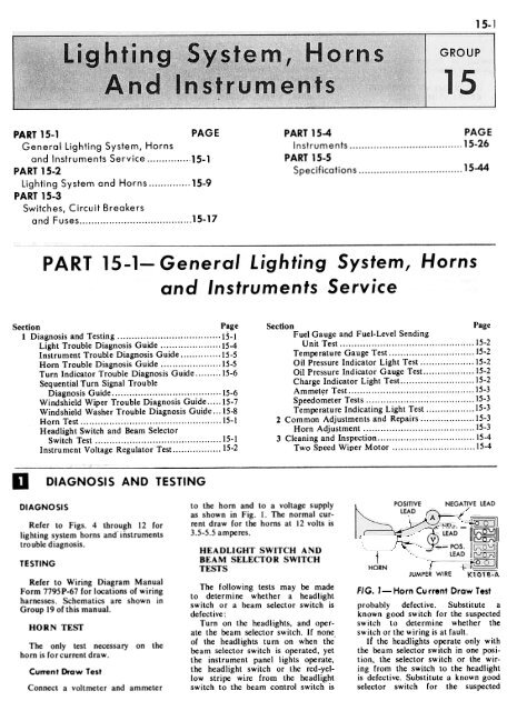
Current Draw Test<br />
Connect a voltmeter <strong>and</strong> ammeter<br />
to the horn <strong>and</strong> to a voltage supply<br />
as shown in Fig. 1. The normal current<br />
draw for the horns at 12 volts is<br />
3.5-5.5 amperes.<br />
HEADLIGHT SWITCH AND<br />
BEAM SELECTOR SWITCH<br />
TESTS<br />
The following tests may be made<br />
to determine whether a headlight<br />
switch or a beam selector switch is<br />
defective:<br />
Turn on the headlights, <strong>and</strong> operate<br />
the beam selector switch. If none<br />
of the headlights turn on when the'<br />
beam selector switch is operated, yet<br />
the instrument panel lights operate,<br />
the headlight switch or the red-yellow<br />
stripe wire from the headlight<br />
switch to the beam control switch is<br />
HORN<br />
FIG. l-Horn<br />
POSITIVE<br />
LEAD<br />
NEGATIVE LEAD<br />
(,~ LEAD -II~II<br />
.J -- pas.<br />
LEAD<br />
JUMPER WIRE<br />
,-- ~.u--<br />
Current Draw Test<br />
probably defective. Substitute a<br />
known good switch for the suspected<br />
switch to determine whether the<br />
switch or the wiring is at fault.<br />
If the headlights operate only with<br />
the beam selector switch in one position.<br />
the selector switch or the wiring<br />
from the switch to the headlight<br />
is defective. Substitute a known good<br />
selector switch for the suspected
<strong>15</strong>-2<br />
GROUP <strong>15</strong>-<strong>Lighting</strong> System, Horn~ And <strong>Instruments</strong><br />
switch to determine whether the<br />
switch or the wiring is at fault.<br />
INSTRUMENT VOLTAGE<br />
REGULATOR TEST<br />
Turn the ignition switch on,<br />
check for voltage at the gauge feed<br />
wire (black with green stripe) at one<br />
of the gauges. The voltage should<br />
oscillate between zero <strong>and</strong> about 10<br />
volts. If it does not, the constant<br />
voltage regulator is defective, or<br />
there is a short to ground between<br />
the voltage regulator <strong>and</strong> the gauges.<br />
If a gauge unit is inaccurate or<br />
does not indicate, replace it with a<br />
new unit. If the gauge unit still is<br />
erratic in its operation, the sending<br />
unit or wiring to the sending unit is<br />
faulty.<br />
If both the fuel gauge <strong>and</strong> the<br />
te mperature gauge indicate improperly<br />
<strong>and</strong> in the same direction, the<br />
constant ~oltage regulator could be<br />
defecti~e, as it supplies both gauges.<br />
FUEL GAUGE AND FUEL<br />
LEVEL SENDING UNIT<br />
TEST<br />
Disconnect the wire from the fuel<br />
level sending unit <strong>and</strong> connect it to<br />
a known good sending unit. Using a<br />
jumper for a ground, connect it to<br />
the sending unit mounting plate <strong>and</strong><br />
car frame. Raise the float arm to<br />
the upper stop, the instrument panel<br />
gauge should read full. Lower the<br />
float arm to the bottom stop, the<br />
gauge should read empty.<br />
If the gauge reads properly, the<br />
sending unit in the gas tank is defective.<br />
If the gauge unit still indicates improperly<br />
or is erratic in its operation,<br />
the gauge unit or the wiring to the<br />
gauge unit is faulty. Repair the wire<br />
or replace the gauge unit.<br />
TEMPERATURE<br />
GAUGE TEST<br />
Start the engine <strong>and</strong> allow it to<br />
run at 1200 rpm for 30 minutes.<br />
Place a thermometer in the coolant<br />
at the radiator filler cap. The temperature<br />
should read a minimum of<br />
1800 F., <strong>and</strong> the gauge in the instrument<br />
panel should indicate within<br />
the normal b<strong>and</strong>.<br />
If the gauge does not indicate,<br />
short the temperature sender unit<br />
terminal wire to ground (ignition<br />
switch on). Do not leave the sender<br />
wire grounded longer than necessary<br />
to make the test, as the gauge may<br />
be damaged. If the gauge now indicates,<br />
the sender unit is defective or<br />
not properly sealed to the engine. Be<br />
sure to ~e an electrically conductive<br />
sealer C3AZ-19554-B. If the gauge<br />
does not indicate, the gauge, the<br />
wires leading to the gauge, or the<br />
constant voltage regulator are at<br />
fault.<br />
OIL PRESSURE INDICATOR<br />
LIGHT TEST<br />
To test the indicator light, turn on<br />
the ignition switch. Do not start the<br />
engine. The light should come on.<br />
Start the engine. Th~ light should go<br />
out, indicating that the oil pressure<br />
has built up a safe value.<br />
To test the oil pressure switch on<br />
the engine, turn the ignition switch<br />
on, engine not running, the indicator<br />
light should come on. If the indicator<br />
light does not come on, short the<br />
terminal of the oil pressure switch<br />
unit to ground. If the light now<br />
comes on, the oil pressure switch is<br />
defective or not properly sealed to<br />
the engine. Be sure to use electrically<br />
conductive sealer C3AZ-19S54-B.<br />
If the light still does not come on,<br />
the bulb is burned out or the wires<br />
from the bulb to the ignition switch<br />
<strong>and</strong> oil pressure switch are defective.<br />
OIL PRESSURE INDICATOR<br />
GAUGE TEST<br />
Remove the oil pressure sender<br />
unit <strong>and</strong> temporarily attach an oil<br />
pressure gauge in its place. Operate<br />
the engine to determine the oil pressure.<br />
If the oil pressure is normal,<br />
the gauge should indicate within the<br />
normal b<strong>and</strong>.<br />
If the gauge did not indicate, momentarily<br />
short the oil pressure<br />
sender wire to ground. Do not leave<br />
the sender wire grounded longer<br />
than necessary to make the test, as<br />
the gauge may be damaged. If the<br />
gauge now indicates, the sender unit<br />
is defective or not properly sealed to<br />
the engine. Be sure to use electrically<br />
conductive sealer C3AZ-<br />
I 9554-B. If the gauge does not indicate,<br />
the jauge. the wires leading<br />
to the gauge or the constant voltage<br />
regulator are at fault.<br />
The sending unit used with the<br />
warning indicator light system is not<br />
interchangeable with the sending unit<br />
used with the gauge system. Refer<br />
to the Ford Car Master Parts Catalog<br />
for proper parts usage.<br />
Misuse of the sending units will<br />
result in inoperative oil pressure<br />
warning systems <strong>and</strong> damaged sending<br />
units or gauges.<br />
CHARGE INDICATOR<br />
TEST<br />
LIGHT<br />
To test the charge indicator light,<br />
turn the ignition switch on with the<br />
engine stopped. The light should<br />
come on. If it does not, the bulb is<br />
burned out, or the wiring to the light<br />
is defective.<br />
An open resistor wire in the Ford<br />
alternator charging system wiring<br />
harness will usually cause the charge<br />
indicator light to stay on until the<br />
engine speed is increased to several<br />
thous<strong>and</strong> rpm. This effect will be noticed<br />
each time the engine is started.<br />
In some cases the light will not go<br />
out at all.<br />
The charge indicator light may be<br />
tested with the use of a test light<br />
containing a trade number 67 or<br />
1<strong>15</strong>5 bulb.<br />
Disconnect the regulator plug<br />
from the regulator. Turn the ignition<br />
switch to ACC position. Touch one<br />
test probe from test light to the ignition<br />
terminal <strong>and</strong> the other to the<br />
regulator base. The test light will<br />
come on if the circuit is in proper<br />
working order. If the <strong>15</strong> ohm resistor<br />
or circuit is open, the indicator<br />
light will operate at full brightness<br />
<strong>and</strong> the test light will be out.<br />
Block - Red<br />
~Stri~e ".<br />
p"",<br />
;HT<br />
'//0<br />
r;:-<br />
w Strip e I<br />
"-- "'V ~,.<br />
RED LIGHT PROVE OUT<br />
SWITCH CONTACTS<br />
CLOSE IN START POSITI~<br />
~ I<br />
IGNITION SWITCH<br />
TERMINAL<br />
K<strong>15</strong>81.~<br />
FIG. 2- Temperature Indicator Light<br />
System
PART <strong>15</strong>-1-General <strong>Lighting</strong> System, <strong>Horns</strong> And <strong>Instruments</strong> Service<br />
<strong>15</strong>-3<br />
AMMETER TEST<br />
To test the ammeter, turn the<br />
headlights on with the engine<br />
stopped. The meter pointer should<br />
move toward the D or discharge<br />
scale. If no movement of the needle<br />
is observed, check the rear of the<br />
meter housing to see if the battery<br />
to circuit breaker wire connections<br />
are loose. If the connections are<br />
tight, <strong>and</strong> the meter does not indicate<br />
a discharge, the meter is inoperative.<br />
If the meter pointer moves<br />
toward the C or charge scale when<br />
the headlights are turned ON, the<br />
wi re connections at the meter are reversed.<br />
When the headlights are<br />
turned on, the battery is reversed, or<br />
the wire passes through the loop in<br />
the wrong direction. Feed the wire<br />
through in the opposite direction to<br />
correct this condition, after checking<br />
first to make sure that the battery is<br />
not reversed.<br />
SPEEDOMETER TESTS<br />
To test the odometer accuracy,<br />
drive the car over a measured mile.<br />
Speedometer accuracy can be<br />
checked by comparing the speedometer<br />
in question against one known<br />
to be accurate, while two cars are<br />
moving at the same speed, or by<br />
timing the car on a measured mile.<br />
The Ford Car Master Parts
<strong>15</strong>-4 GROUP 1 S-Lighti ng System, <strong>Horns</strong> And <strong>Instruments</strong><br />
CLEANING AND INSPECTION<br />
TWO-SPEED WIPER MOTOR<br />
I. Clean the gear housing of all<br />
old grease. Do not allow any cleaning<br />
fluid to contact the armature<br />
shaft <strong>and</strong> output shaft bearings.<br />
2. Wipe all other parts with a<br />
clean cloth.<br />
3. Inspect the gear housing for<br />
cracks or distortion. Replace a<br />
cracked or distorted housing.<br />
4. Check all shafts, bushings, <strong>and</strong><br />
gears for scored surfaces. Replace<br />
defective parts <strong>and</strong> add new grease<br />
to the housing <strong>and</strong> gears.<br />
ALL HEADLIGHTS DO<br />
NOT LIGHT<br />
1. Loose battery cable.<br />
2. Loose quick disconnect or broken<br />
wire from the battery to the<br />
headlight switch.<br />
3. Defective headlight switch.<br />
4. Disconnected or broken wire<br />
from the headlight switch to the<br />
beam selector switch.<br />
S. Loose or broken wire to the<br />
bulbs.<br />
6. Defective beam selector switch.<br />
7. All headlight bulbs burned out.<br />
This may be caused by a defective<br />
or improperly adjusted alternator<br />
voltage regulator (Group 13).<br />
INDIVIDUAL LIGHTS<br />
DO NOT LIGHT<br />
LIGHTS BURN OUT<br />
REPEATEDLY<br />
FIG. 4-Light Trouble Diagnosis Guide<br />
1. Burned out bulb.<br />
2. Loose or broken wires to the<br />
bulb.<br />
I. Loose or corroded electrical<br />
connections.<br />
2. Excessive vibration.<br />
3. Poor ground<br />
3. Improperly adjusted or defective<br />
alternator voltage regulator<br />
(Group 13).
PART 1S-1-General <strong>Lighting</strong> System, <strong>Horns</strong> And <strong>Instruments</strong> Service<br />
<strong>15</strong>-5<br />
OIL PRESSURE INDICATOR<br />
LIGHT INOPERATIVE<br />
1. Indicator bulb burned out.<br />
2. Loose or broken wire from the<br />
light to the indicator switch.<br />
3. Defective oil pressure sender<br />
unit (in this part).<br />
CHARGE INDICATOR<br />
LIGHT INOPERATIVE<br />
CHARGE INDICA TOR<br />
LIGHT STAYS ON AT<br />
IDLE<br />
OIL PRESSURE INDICATOR<br />
GAUGE INOPERATIVE<br />
AMMETER GAUGE<br />
INOPERA TIVE<br />
FUEL GAUGE ERRATIC<br />
OR INOPERATIVE<br />
1. Burned out bulb.<br />
2. Loose or broken wires.<br />
1. Loose or broken drive belt.<br />
2. Parallel resistance wire (<strong>15</strong><br />
-ohm) burned out.<br />
3. Loose connections or broken<br />
wires.<br />
1. Loose or broken wire from the<br />
constant voltage regulator to the oil<br />
pressure gauge.<br />
2. Grounqed or broken wire from<br />
1. Defective gauge (in this part).<br />
2. Loose or broken wires.<br />
1. Loose or broken wire from the<br />
constant voltage regulator to the fuel<br />
gauge.<br />
2. Defective fuel gauge.<br />
3. Loose, broken, or shorted wire<br />
from fuel gauge to the fuel tank<br />
sending unit.<br />
3. Defective alternator regulator.<br />
4. Regulator out of adjustment.<br />
5. Grounded wiring from alterna.<br />
tor to regulator.<br />
6. Defective alternator.<br />
the engine oil pressure sending unit.<br />
3. Defective gauge.<br />
4. Defective oil pressure sending<br />
unit.<br />
3. Charging system malfunction<br />
4. Defective constant voltage regulator.<br />
5. Defective fuel tank sending<br />
unit.<br />
6. Poor ground between fuel tank<br />
<strong>and</strong> body.<br />
TEMPERATURE GAUGE<br />
ERRATIC OR INOPERATIVE<br />
1. Loose or broken wire from constant<br />
voltage regulator to the temperature<br />
gauge.<br />
2. Defective temperature gauge.<br />
3. Loose or broken wire from the<br />
temperature sending unit to the tem-<br />
perature gauge.<br />
4. Defective temperature sending<br />
unit.<br />
5. Defective constant voltage regulator.<br />
FUEL, TEMPERATURE, AND<br />
OIL PRESSURE GAUGES<br />
ERRATIC<br />
1. Loose or corroded constant<br />
voltage regulator ground.<br />
2. Defective constant voltage regulator.<br />
3. Broken or loose wire from or<br />
to the constant voltage regulator.<br />
4. Defective ignition switch.<br />
FIG. 5.<br />
Instrument Trouble Diagnosis Guide<br />
FIG. 6.<br />
Horn Trouble Diagnosis Guide
<strong>15</strong>-6 GROUP <strong>15</strong>-<strong>Lighting</strong> System, <strong>Horns</strong> And <strong>Instruments</strong><br />
OUTSIDE TURN SIGNAL<br />
LIGHTS INOPERATIVE<br />
1. Burned out bulbs, or loose<br />
socket connections.<br />
2. Open connection at turn signal<br />
flasher.<br />
3. Loose or broken wire from<br />
ignition switch to flasher.<br />
4. Defective flasher.<br />
5. Loose or broken wire from<br />
flasher to turn signal switch.<br />
6. Defective turn signal switch.<br />
7. Broken, shorted, or loose wires<br />
from switch to lights.<br />
INSTRUMENT PANEL<br />
TURN SIGNAL LIGHTS<br />
OPERATE INCORRECTLY<br />
I. Burned out bulb, or improper<br />
connection at socket.<br />
2. Loose, broken, or shorted wires<br />
from switch to lights.<br />
3. Inoperative outside turn signal<br />
lights (See above).<br />
TURN SIGNAL<br />
CANCELS IMPROPERLY<br />
I. Cam improperly positioned on<br />
steering wheel hub.<br />
2. Coil spring on switch plate assembly<br />
loose or weak.<br />
FIG. 7<br />
St<strong>and</strong>ard Turn Signal Trouble Diagnosis Guide<br />
All TURN SIGNALS<br />
INOPERA TIVE<br />
I. Defective fuse.<br />
2. Open circuit between fuse panel<br />
<strong>and</strong> turn signal switch.<br />
3. Poor ground for turn signal<br />
relay <strong>and</strong> sequential flasher in luggage<br />
compartment.<br />
4. Defective turn signal switch.<br />
5. Open circuit between turn signal<br />
relay (dash panel) <strong>and</strong> turn signal<br />
switch.<br />
6. Open circuit in turn signal relay<br />
(dash panel).<br />
7. No electrical feed (open wire)<br />
between the turn signal relay (instrument<br />
panel) <strong>and</strong> the sequential flasher<br />
in the luggage compartment.<br />
8. Defective sequential turn signal<br />
flasher assembly (luggage compartment).<br />
LEFT OR RiGHT FRONT<br />
TURN SIGNAL DOES NOT<br />
OPERATE (TURN INDICATOR<br />
LIGHT REMAINS ON AND<br />
REAR LIGHTS OPERATE)<br />
1. Turn signal filament of bulb<br />
burned out.<br />
2. Corrosion or foreign matter on<br />
bulb or socket terminal.<br />
3. Open circuit between the bulb<br />
<strong>and</strong> the t urn signal relay.<br />
4. Defective turn signal relay or<br />
wiring in the luggage compartment.<br />
5. Loose connectors in wiring from<br />
luggage compartment to bulb(s).<br />
REAR TURN SIGNALS<br />
INOPERA TIVE-ONE SIDE,<br />
BOTH SIDES, OR INDIVIDUAL<br />
BULBS (FRONT LIGHTS<br />
FLASH CORRECTLY)<br />
I. Turn signal filament of bulb<br />
burned out.<br />
2. Open circuits in rear turn signal<br />
wiring between turn signal relay<br />
in luggage compartment <strong>and</strong> turn signal<br />
bulbs.<br />
3. Incorrect operation of the turn<br />
signal relay.<br />
4. Open circuit between the sequential<br />
flasher assembly <strong>and</strong> the turn signal<br />
relay.<br />
5. Defective sequential flasher<br />
assembly.<br />
FIG. 8.<br />
.Sequential-Turn SiQnal Trau ble DiaQnosis Guide -External Signals
PART <strong>15</strong>-1-General <strong>Lighting</strong> System, <strong>Horns</strong> And <strong>Instruments</strong> Service<br />
<strong>15</strong>-7<br />
LEFT INDICATOR BULB<br />
FLASHES FOR RIGHT OR<br />
LEFT TURN, OR LEFT ONLY<br />
INDICATOR BULB FLASHES<br />
FOR EMERGENCY FLASHER<br />
1. Open solenoid feed circuit between<br />
turn signal switch <strong>and</strong> the<br />
turn signal indicator relay (4 wire).<br />
2. Wire No. 50 (green-white stripe)<br />
<strong>and</strong> wire No. 49 (white-blue stripe),<br />
are reversed in connector to turn<br />
signal indicator relay (4 wire).<br />
3. Defective turn signal indicator<br />
relay (4 wire).<br />
BOTH INDICA TOR BULBS<br />
FLASH IN EITHER DIRECTION<br />
1. Open circuit between solenoid<br />
of emergency warning relay <strong>and</strong> the<br />
turn signal switch.<br />
2. Defective<br />
relay.<br />
emergency<br />
warning<br />
LEFT OR RIGHT INDICATOR<br />
BULB INOPERATIVE<br />
I. Defective bulb.<br />
2. Inadequate ground at bulb.<br />
socket.<br />
3. Open feed circuit between turn<br />
signal indicator relay (4 wire), <strong>and</strong><br />
bulb.<br />
4. Defective turn signal indicator<br />
relay (4 wire).<br />
BOTH INDICA TOR BULBS<br />
WILL NOT LIGHT<br />
I. Defective bulbs.<br />
2. Open circuit between turn signal<br />
relay (3 wire), <strong>and</strong> the turn signal<br />
indicator relay (4 wire).<br />
3. Open circuit between the turn<br />
signal indicator relay (4 wire), <strong>and</strong><br />
the bulbs.<br />
4. Defective turn signal relay (3<br />
wire).<br />
S. Defective turn signal indicator<br />
relay (4 wire).<br />
ONE INDICA TOR BULB<br />
LIGHTS STEADY, BUT<br />
DOES NOT FLASH<br />
I. Defective turn signal bulb or<br />
bulbs in system.<br />
BOTH INDICA TOR BULBS<br />
LIGHT STEADY, BUT DO<br />
NOT FLASH<br />
I. Defective turn signal indicator<br />
bulb or bulbs in system.<br />
2. Defective turn signal relay (3<br />
wire).<br />
FIG. 9.<br />
.Sequential Turn Signal Trouble Diagnosis Guide Instrument Ponel Bulbs<br />
FIG. 10- Windshield Wiper Trouble Diagnosis Guide
<strong>15</strong>-8 GROUP <strong>15</strong>-<strong>Lighting</strong> System, <strong>Horns</strong> And <strong>Instruments</strong><br />
I. Defective electrical switch assembly<br />
at the foot pedal.<br />
2. Open circuit between foot pedal<br />
switch <strong>and</strong> wiper motor.<br />
3. Defective windshield wiper<br />
switch.<br />
4. Open circuit between windshield<br />
wiper switch <strong>and</strong> wiper motor.<br />
5. Defective wiper motor.<br />
FIG. ll-Foot-Pedal Windshield Washer System Diagnosis Guide<br />
1. No fluid in washer reservoir or<br />
lines.<br />
2. Broken or clogged water lines.<br />
3. Open circuit between switch <strong>and</strong><br />
pump.<br />
4. Open circuit between washer<br />
pump <strong>and</strong> wiper motor.<br />
5. Defective wiper switch.<br />
6. Defective washer pump.<br />
7. Defective switch on wiper motor.<br />
8. Burned, corroded, or damaged<br />
switch plate in wiper motor.<br />
9. Defective wiper motor.<br />
FIG. 12- Electric Windshield Woshe r Pump-DioQnosis<br />
Guide
~<br />
,gnatsuM Cougar<br />
thgiliaT thgiliaT Lens-Cougar<br />
Lens-Mustang<br />
,gnatsuM-thgiL Cougar<br />
thgiliaT thgiliaT Body-Cougar<br />
Body-Falcon<br />
noitatS Wagons<br />
thgiliaT Dor-Fairlane<br />
thgiliaT Body-Mustang<br />
thgiliaT Dor-Cougar<br />
pukcaB Light Body-Cougar, Mustang<br />
thgiliaT Dor-Mustang<br />
Taillight Body Lens <strong>and</strong> BulbsenalriaF<br />
Model 71 ,<br />
<strong>and</strong><br />
Falcon, Fairlane, Mercury Intermediate<br />
Transmission Control Selector Light-<br />
Console Transmission Control Selector<br />
Taillight Lens-Falcon, Mercury<br />
Tail Intermediate <strong>and</strong> Stop Light Bulbs-Except<br />
License Plate Light Assy. -Except<br />
<strong>15</strong>-9<br />
<strong>15</strong>-14<br />
<strong>15</strong>-14<br />
<strong>15</strong>-14<br />
<strong>15</strong>-14<br />
<strong>15</strong>-14<br />
...<strong>15</strong>-<strong>15</strong><br />
<strong>15</strong>-<strong>15</strong><br />
<strong>15</strong>-<strong>15</strong><br />
<strong>15</strong>-<strong>15</strong><br />
<strong>15</strong>-<strong>15</strong><br />
<strong>15</strong>-<strong>15</strong><br />
<strong>15</strong>-<strong>15</strong><br />
<strong>15</strong>-<strong>15</strong><br />
<strong>15</strong>-16<br />
<strong>15</strong>-16<br />
esneciL raguoC Plate <strong>and</strong> Bulb Station <strong>and</strong>/or Wagons<br />
Lens<br />
,<strong>15</strong>-16<br />
<strong>15</strong>-16<br />
DESCRIPTION AND OPERATION<br />
Refer to Wiring Diagram Manual<br />
Form 7795P-67 for locations of wiring<br />
harnesses. Schematics are shown<br />
in Group 19 of this manual.<br />
ORANGE<br />
(VACUUM<br />
SOURCE)<br />
-<br />
WHITE<br />
;1::;;; -,<br />
k,<br />
~.. 0 A 0 .."-- ./""<br />
~---,:,:'/' , C5<br />
'/ "'-:=:--<br />
~ ~~~ /'-. -~~<br />
YELLOW<br />
~\\\\<br />
J"" ~.<br />
RII"D"~~ "'!:LLOW<br />
,<br />
BUMP<br />
-~~<br />
1675~ "":,\ PI:<br />
VAC<br />
MOT<br />
~<br />
'.I~:::24 J¥~<br />
'V~ I'" '<br />
\ ,-<br />
/ .--/ YELLOW<br />
~BUMPER<br />
379352-5<br />
1 ';,<br />
GREEN<br />
HEADLIGHTS<br />
The Falcon <strong>and</strong> Mustang use two<br />
No.2 type sealed-beam headlights.<br />
SOLENOID VAOJUM<br />
i<br />
I<br />
RESERVOIR<br />
13A185<br />
VENT<br />
~;C;"'oi<br />
,.<br />
GREEN<br />
CONNECTOR<br />
13A169<br />
YELLOW<br />
,"<br />
;) "" \ ~ ..."' MOTOR<br />
\ ...<br />
'1'\i:<br />
~;:~~;:- I:'~'<br />
~~~~~<br />
~I<br />
PIN \<br />
13A173<br />
j
<strong>15</strong>-10 GRO UP lS-<strong>Lighting</strong> System, <strong>Horns</strong> And <strong>Instruments</strong><br />
light is in the lower position <strong>and</strong> the<br />
No. 2 light is in the upper position.<br />
The Cougar uses four sealed-beam<br />
headlights. The No. I light is in<br />
the inner position <strong>and</strong> the No.2<br />
light is in the outer position.<br />
A conventional beam selector<br />
switch is located on the floorboard<br />
at the left of the driver.<br />
Quick disconnect terminals are also<br />
provided at the left <strong>and</strong> right of<br />
the radiator support assembly. The<br />
terminals are color coded. Like<br />
colored terminals are connected together.<br />
HEADLIGHT COVERS<br />
-COUGAR<br />
The headlight covers are opened<br />
<strong>and</strong> closed by the use of vacuum<br />
motors. Refer to Fig. I for location<br />
of the headlight cover operating components<br />
<strong>and</strong> installation. Note the<br />
vacuum hose routing, connections <strong>and</strong><br />
color codes.<br />
The headlight switch, when pulIed<br />
fulI out, connects the headlight circuit<br />
to a solenoid. The solenoid operates<br />
vacuum ports in a distribution valve<br />
which applies vacuum to the cover<br />
operating vacuum motors. The solenoid<br />
also opens a vacuum relief (exhaust)<br />
port to that side of the vacuum<br />
motor diaphragm to which vacuum<br />
is not applied. The vacuum exhaust<br />
port is vented through a tube into<br />
the passenger compartment in order<br />
to prevent engine oil fumes from entering<br />
the distribution valve.<br />
Two cover hinge springs, attached<br />
to each cover, function as over-center<br />
type springs, which help hold the<br />
covers in the open or closed position.<br />
Vacuum applied to either side of the<br />
vacuum motor diaphragm during<br />
opening or closing, overcomes this<br />
spring tension.<br />
Two reserve vacuum reservoirs<br />
provide vacuum storage which permits<br />
limited cycling of the headlight<br />
covers without the car engine running.<br />
In case of vacuum loss or solenoid<br />
failure, the covers can be opened or<br />
closed manually as follows: To open<br />
or close the covers, push in the<br />
plunger located on the vacuum distribution<br />
valve (View C, Fig. I), located<br />
behind the left headlights in the<br />
engine compartment; then, if the<br />
covers do not open, open them by<br />
h<strong>and</strong> while the plunger is in the in<br />
position. To reset the system for automatic<br />
operation, press inward on the<br />
end of the plunger so that the plunger<br />
return spring returns the plunger to<br />
the out position.<br />
The headlight covers should be<br />
open (raised) when washing the car<br />
to clean the headlights for safer nighttime<br />
driving.<br />
HORNS<br />
A pair of tuned horns are used.<br />
The horn button closes the circuit to<br />
the horns. One of the horns has a<br />
high-pitched tone; the other has a<br />
low-pitched tone.<br />
IN-VEHICLE ADJUSTMENTS AND REPAIRS<br />
HEADLIGHT ALIGNMENT<br />
All headlight adjustments should<br />
be made with a half-full tank<br />
plus or minus one gallon, with a person<br />
seated in the driver's seat <strong>and</strong> a<br />
person seated in the passenger seat,<br />
the car unloaded <strong>and</strong> the trunk empty<br />
except for the spare tire <strong>and</strong> jacking<br />
equipment, <strong>and</strong> recommended pressure<br />
in all tires. Before each adjustment,<br />
bounce the car by pushing on<br />
the center of both the front <strong>and</strong> rear<br />
bumpers, to level the car.<br />
To align the No. I headlights by<br />
means of a wall screen, select a level<br />
portion of the shop floor. Layout<br />
the floor <strong>and</strong> wall as shown in Fig. 2.<br />
Establish the headlight horizontal<br />
centerline by subtracting 20 inches<br />
from the actual measured height of<br />
the headlight lens center from the<br />
floor <strong>and</strong> addin~ this difference to the<br />
20-inch reference line obtained by<br />
sighting over the uprights to obtain<br />
dimension B (upper diagram Fig.<br />
3). Draw a horizontal line 2 inches<br />
below, <strong>and</strong> parallel to the headlight<br />
horizontal centerline. Then draw the<br />
headlight vertical centerlines on the<br />
screen as measured on the vehicle<br />
(dimension A, upper diagram Fig. 3).<br />
NO.1 HEADLIGHT HIGH<br />
BEAM ADJUSTMENT<br />
Adjust each No. I headlight beam<br />
as shown in Fig. 3 upper diagram.<br />
Cover the No.2 lights when making<br />
this adjustment.<br />
Some states may not approve of<br />
the 2-inch dimension for the No.1<br />
headlights. Check the applicable state<br />
law, as a 3-inch dimension may be<br />
required.<br />
NO.2 HEADLIGHT LOW<br />
BEAM ADJUSTMENT<br />
To align the No.2 headlights. a<br />
new wall chart is used. Dimension B<br />
for the No.2 lights will be different<br />
than B for the No. I lights. but dimension<br />
A which is measured on the car<br />
will be the same as for the No. I<br />
lights. Note that the line of adjustment<br />
of the No.2 lights is the horizontal<br />
centerline of the No.2 lights.<br />
Turn the headlights to low beam <strong>and</strong><br />
adjust each No.2 light as shown in<br />
Fig. 3.<br />
Each headlight can be adjusted by<br />
means of two screws located under<br />
the headlight trim ring. Always bring<br />
each beam into final position by<br />
turning the adjusting screws clockwise<br />
so that the headlights will be<br />
held against the tension springs when<br />
the operation is comoleted (Fig. 4).
PART lS-2-<strong>Lighting</strong> System And <strong>Horns</strong> <strong>15</strong>-<br />
FIG. 2.<br />
Floor <strong>and</strong> Wall Layout<br />
HEADLIGHTS 25 FEET<br />
FROM WAll<br />
NO.1<br />
LIGHT HIGH BEAM DIAGRAM<br />
14 DIMENSION "A" .\<br />
NO.2<br />
LIGHT LOW BEAM DIAGRAM<br />
Kl192-C<br />
FIG. 3-Headlight<br />
Wall Screens
~<br />
..c<br />
0 '"<br />
N<br />
~<br />
Co...<br />
rc<br />
) .-<br />
m<br />
~<br />
!!!<br />
j:illi<br />
,<br />
'"<br />
'"<br />
«,<br />
~<br />
'"<br />
~<br />
I-<br />
::> 7<br />
:;t;j<br />
,., ,::<br />
~~<br />
~<br />
~<br />
""" ~<br />
.-<br />
~<br />
'"<br />
w<br />
><br />
0"<br />
/ '<br />
'" , ~<br />
, t1. ~ "'O uO "'- ,,;1<br />
f-<br />
~<br />
~<br />
'"<br />
::""<br />
-~<br />
~ Z-o<br />
~<br />
-0.<br />
~.<br />
~<br />
w<br />
~~<br />
«;;<br />
'"<br />
-'<br />
, I-<br />
0< .<br />
"- W<br />
w I<br />
a~<br />
~'" 0:<br />
J:<br />
PART 1 S-2-<strong>Lighting</strong> System And <strong>Horns</strong> <strong>15</strong>-13<br />
REMOVAL AND INST ALLA TION<br />
HEADLIGHTS<br />
On the Cougar it will be necessary<br />
to open the hood <strong>and</strong> release the vacuum<br />
valve (place the valve in manual<br />
position) <strong>and</strong> manually open the headlight<br />
cover.<br />
1. Remove the screws <strong>and</strong> remove<br />
the headlight trim ring (Fig. 4).<br />
2. Place a h<strong>and</strong> over the headlight<br />
assembly <strong>and</strong> unhook the spring<br />
from the retaining ring.<br />
3. Remove the retaining ring by<br />
unhooking the ring from the clip located<br />
directly across the bulb from<br />
the spring hook.<br />
4. Pull the headlight bulb forward<br />
<strong>and</strong> disconnect the wiring assembly<br />
plug.<br />
5. Plug in the new bulb <strong>and</strong> place<br />
it in position, locating the bulb glass<br />
tabs in the positioning slots.<br />
6. Hook the retaining ring over<br />
the clip, then over the bulb <strong>and</strong> secure<br />
it with the existing ball-ring<br />
spring.<br />
7. Align the bulb with the wall<br />
screen.<br />
8. Install the trim ring in position<br />
<strong>and</strong> install the retaining screws.<br />
HEADLIGHT COVER VACUUM<br />
MOTOR-COUGAR<br />
REMOVAL<br />
Refer to Group 17 of this manual<br />
for illustration showing grille attaching<br />
parts.<br />
1. Open the hood <strong>and</strong> remove the<br />
four screws which retain the center<br />
grille panel to the hood latch support<br />
brace.<br />
2. Remove the headlight cover return<br />
springs.<br />
3. Remove two capscrews which<br />
retain the grille center.<br />
4. Remove two retaining screws<br />
from the grille outer end.<br />
5. Remove the two stud nuts which<br />
retain the grille outer end.<br />
6. Pull the grille assembly out<br />
from around the headlights.<br />
7. Disconnect the vacuum motor<br />
lower vacuum hose from the vacuum<br />
motor. Remove the through bolt <strong>and</strong><br />
nut from the bottom of the vacuum<br />
motor.<br />
8. Disconnect the headlight wiring<br />
connectors from the headlights <strong>and</strong><br />
lift out the vacuum motor assembly.<br />
INSTAllATION<br />
1. Position the vacuum motor assembly<br />
<strong>and</strong>, reaching under the car,<br />
install the retaining through bolt<br />
<strong>and</strong> nut. Connect the lower vacuum<br />
hose to the vacuum motor.<br />
2. Connect the upper vacuum hose<br />
to the vacuum motor <strong>and</strong> connect the<br />
headlight wiring connector plug.<br />
3. Position the grille in the<br />
grille opening <strong>and</strong> install the two<br />
retaining stud nuts.<br />
4. Install the two grille top retaining<br />
screws <strong>and</strong> the two capscrews<br />
which retain the grille center.<br />
5. Install the two headlight cover<br />
return springs.<br />
6. Install the vacuum motor to<br />
headlight cover retaining clip.<br />
7. Position the center grille panel<br />
to the grille <strong>and</strong> install the four center<br />
panel retaining capscrews.<br />
8. Start the engine <strong>and</strong> check<br />
headlights <strong>and</strong> headlight covers for<br />
proper operation.<br />
WIRING ASSEMBLY-DASH<br />
TO HEADLIGHT JUNCTION<br />
(14290 WIRING HARNESS)<br />
-FAIRLANE, FALCON,<br />
MERCURY INTERMEDIATE<br />
I. Disconnect the battery ground<br />
cable from the battery.<br />
2. Disconnect the harness plug connector<br />
at the dash panel.<br />
3. Open the wiring retainer along<br />
the left fender apron.<br />
4. Disconnect the alternator wiring<br />
connector. Remove the ground wire<br />
retaining screw at the alternator regulator.<br />
Disconnect the left headlight<br />
<strong>and</strong> parking light wiring connectors.<br />
5. Remove the wiring leads (blackyellow<br />
stripe <strong>and</strong> yellow wires) from<br />
the starting motor solenoid. Open the<br />
wiring retaining clips on the right<br />
fender apron. Disconnect the right<br />
headlight <strong>and</strong> the right parking light<br />
wiring connectors.<br />
6. Open the wiring retaining clips<br />
across the top of the radiator support<br />
<strong>and</strong> work the harness out from right<br />
to left. Remove the harness out<br />
through the hole at the alternator<br />
regulator.<br />
7. Position the new wiring assembly<br />
in the engine compartment, working<br />
from left to right through the routing<br />
hole in the left radiator side support<br />
near the alternator regulator.<br />
8. Connect the wiring leads to the<br />
starting motor solenoid. Install the<br />
wiring in the retaining clips on the<br />
right fender apron. Connect the headlights,<br />
parking light <strong>and</strong> horn connectors.<br />
Position the wiring in the retaining<br />
clips across the radiator support.<br />
9. Connect the left headlights,<br />
parking light <strong>and</strong> horn. Connect the alternator<br />
regulator wiring connector.<br />
Install the ground wire <strong>and</strong> radio<br />
suppressor ground wire retaining<br />
screw.<br />
10. Place the wiring harness in the<br />
wiring retainers along the left fender<br />
apron <strong>and</strong> connect the wiring connector<br />
at the dash panel.<br />
11. Connect the battery ground cable<br />
to the battery.<br />
12. Check operation of the headlights,<br />
parking lights <strong>and</strong> horns.<br />
WIRING ASSEMBLY-DASH TO<br />
HEADLIGHT JUNCTION-<br />
COUGAR AND MUSTANG<br />
1. Disconnect the battery ground<br />
cable.<br />
2. Disconnect two multiple connectors<br />
<strong>and</strong> one single connector under<br />
the instrument panel, push the<br />
grommet <strong>and</strong> connectors through the<br />
hole into the engine compartment.<br />
3. Disconnect the dual brake warning<br />
connector at the brake differential<br />
valve.<br />
4. Open the harness retaining clips,<br />
disconnect the wires from the starter<br />
relay, <strong>and</strong> disconnect the alternator<br />
wiring connector.<br />
5. Disconnect the headlight <strong>and</strong><br />
parking light connectors, the voltage<br />
regulator wires <strong>and</strong> radio suppressor,<br />
<strong>and</strong> the horn leads. On the Cougar<br />
disconnect the headlight housing vacuum<br />
solenoid wire.<br />
6. Remove the screws retaining the<br />
headlight <strong>and</strong> regulator ground wires,<br />
open all harness retaining clips <strong>and</strong><br />
remove the harness from the vehicle.<br />
7. Route the new harness <strong>and</strong><br />
close all the retaining clips.<br />
8. Install the screws retaining the<br />
headlight <strong>and</strong> regulator ground wires.<br />
9. Connect the horns, the starter,<br />
the alternator <strong>and</strong> the headlight <strong>and</strong><br />
parking light wires.<br />
10. Connect the voltage regulator,<br />
wire connector, radio suppressor <strong>and</strong><br />
the dual brake warning connector.<br />
On the Cougar also connect the headlight<br />
vacuum solenoid wire.<br />
11. Push the multiple connectors<br />
through the dash, seat the dash grommet<br />
<strong>and</strong> connect the multiple connectors<br />
at the instrument panel.<br />
12. Connect the battery <strong>and</strong> check<br />
the operation of all connected parts.<br />
PARKING<br />
LIGHT HOUSING-ALL<br />
1. Open the hood <strong>and</strong> disconnect<br />
the connector between the radiator<br />
support <strong>and</strong> grille.
<strong>15</strong>-14 GROUP <strong>15</strong>-<strong>Lighting</strong> System, <strong>Horns</strong> And <strong>Instruments</strong><br />
2. Remove the lead wires from the<br />
retaining clips <strong>and</strong> pull the wire<br />
down.<br />
3. Remove the two screws or retaining<br />
nuts from the housing retainer<br />
<strong>and</strong> remove the lamp assembly <strong>and</strong><br />
housing retainer from the bumper or<br />
stone deflector extension.<br />
4. Remove the lens, gasket <strong>and</strong><br />
bulb from the lamp housing.<br />
5. Install the bulb, gasket <strong>and</strong><br />
lens in the housing.<br />
6. Position the housing <strong>and</strong> retainer<br />
to the bumper or stone deflector<br />
extension <strong>and</strong> install the retaining<br />
screws or nuts.<br />
7. Re-route the lead wires back<br />
to the connector at the radiator support<br />
<strong>and</strong> connect the connector.<br />
8. Position the lead wire in the<br />
retaining clips as required.<br />
PARKING LIGHT<br />
To replace the bulb, remove the<br />
lens retaining screws <strong>and</strong> the lens.<br />
HORNS<br />
Disconnect the horn wire from the<br />
terminal. Remove the horn mounting<br />
bracket to horn retaining screws <strong>and</strong><br />
remove the horn.<br />
To install, mount the horn in position,<br />
then connect the horn wire to<br />
the horn terminal.<br />
HORN BUTTON<br />
1. Disconnect the horn wire connector,<br />
that has a yellow <strong>and</strong> a yellow-green<br />
wire in it, under the instrument<br />
panel, to the left of the<br />
steering column.<br />
2. Press down evenly on the horn<br />
button <strong>and</strong> turn counter-clockwise<br />
until it lifts out from the steering<br />
wheel.<br />
3. Remove the horn button <strong>and</strong><br />
spring.<br />
4. The horn button contacts are integral<br />
with the turn signal switch <strong>and</strong><br />
are removed with the switch.<br />
5. Install the horn button spring<br />
<strong>and</strong> button.<br />
6. Connect the horn wire connector<br />
under the instrument panel.<br />
DOME AND COURTESY<br />
LIGHT (S)<br />
On the Mustang Hardtop, the dome<br />
light bulb can be removed by removing<br />
the screws retaining the dome<br />
light lens. To replace the dome light<br />
bulb in the Falcon, Fairlane <strong>and</strong><br />
Mercury Intermediate it is only necessary<br />
to snap out the dome light lens.<br />
To replace the courtesy light bulb<br />
for Mustangs (except Hardtops) pry<br />
the light assembly out of the lower<br />
rear quarter panel. On the Cougar<br />
the courtesy light is located in the<br />
upper rear quarter panel <strong>and</strong> the<br />
bulb can be replaced by snapping out<br />
the light assembly lens.<br />
INSTRUMENT LIGHTS<br />
The instrument cluster bulbs are<br />
retained in plug-in type sockets. The<br />
instrument cluster light bulbs can<br />
be replaced by pulling out the individual<br />
ligr,t sockets from the rear<br />
of the instrument cluster.<br />
On the Mustang <strong>and</strong> Cougar, bulbs<br />
on the right side of the cluster can<br />
be replaced by reaching under the instrument<br />
panel. Bulbs on the left side<br />
of lhe cluster are replaced by removing<br />
the four heater control retaining<br />
screws <strong>and</strong> positioning the heater control<br />
outward to provide access.<br />
WARNING LIGHT BULBS<br />
ROOF CONSOLE-XR-7 COUGAR<br />
I. Remove two console retaining<br />
screws.<br />
2. Pry the console downward to<br />
free the console retaining clips (two)<br />
from the roof.<br />
3. Replace either of the four bulbs<br />
(seat belt, door, parking brake or low<br />
fuel) as required.<br />
4. Snap the console into place <strong>and</strong><br />
install the two retaining screws.<br />
TRANSMISSION CONTROL<br />
SELECTOR LIGHT (ON<br />
STEERING COLUMN)-FALCON,<br />
FAIRLANE AND MERCURY<br />
INTERMEDIATE<br />
I. Disconnect the battery ground<br />
cable from the battery.<br />
2. Remove the horn ring <strong>and</strong> steering<br />
wheel.<br />
3. Remove the light bulb socket<br />
retaining scrl:w <strong>and</strong> pullout the bulb<br />
<strong>and</strong> socket assembly. Replace the<br />
bulb.<br />
4. Position the bulb <strong>and</strong> socket assembly<br />
<strong>and</strong> install the socket retaining<br />
screw.<br />
5. Install the steering wheel <strong>and</strong><br />
horn ring.<br />
6. Connect the battery ground cable<br />
to the battery.<br />
TRANSMISSION CONTROL<br />
SELECTOR LIGHT-MUSTANG<br />
AND COUGAR<br />
I. Remove the four retaining<br />
screws from the selector lever cover<br />
<strong>and</strong>'dial indicator on the floor,<br />
2. Lift the lever cover assembly<br />
<strong>and</strong> replace the bulb.<br />
3. Position the cover to the floor<br />
<strong>and</strong> install the four cover retaining<br />
screws.<br />
TRANSMISSION CONTROL<br />
SELECTOR LIGHT (ON<br />
CONSOLE)-MUSTANG AND<br />
COUGAR<br />
I. Pry the top finish pad cover<br />
from the console.<br />
2. Remove the two retaining<br />
screws from inside the glove box <strong>and</strong><br />
remove the upper finish panel.<br />
3. Position the selector lever in the<br />
one position <strong>and</strong> remove the light socket<br />
<strong>and</strong> bulb from its retainer.<br />
4. Replace the bulb <strong>and</strong> install the<br />
socket in the retainer.<br />
5. Position the finish panel <strong>and</strong> install<br />
the retaining screws.<br />
6. Snap the finish pad cover into<br />
position.<br />
TAilLIGHT lENS-COUGAR<br />
1. Remove the luggage compartment<br />
rear trim panel.<br />
2. Remove the four bulb <strong>and</strong><br />
socket assemblies from the light body.<br />
3. Remove the six nuts retaining<br />
the light assembly to the body back<br />
panel.<br />
4. Remove the light assembly <strong>and</strong><br />
place it on a work bench.<br />
S. Remove ten nuts <strong>and</strong> remove<br />
the lens <strong>and</strong> door from the light body.<br />
Remove the lens from the door.<br />
6. Position the new lens in the<br />
door.<br />
7. Position the lens <strong>and</strong> door assembly<br />
to the light body <strong>and</strong> install<br />
the ten retaining screws.<br />
8. Position the light assembly to<br />
the car body <strong>and</strong> install the six light<br />
assembly retaining nuts.<br />
9. Plug in the light socket <strong>and</strong><br />
bulbs.<br />
10. Install the luggage compartment<br />
rear trim panel.<br />
TAILLIGHT LENS-MUSTANG<br />
I. Open the rear deck <strong>and</strong> remove<br />
the spare tire.<br />
2. Remove the bulb socket from<br />
the rear I ight body.<br />
3. Remove the six plastic covers<br />
from the ends of the bezel assembly<br />
studs <strong>and</strong> also remove the six retaining<br />
nuts.<br />
4. Pull the light body <strong>and</strong> lens<br />
from the studs <strong>and</strong> remove the assembly<br />
from the vehicle.<br />
5. Remove the six retaining screws<br />
from the lens <strong>and</strong> remove the lens<br />
from the body.
PART <strong>15</strong>-2-<strong>Lighting</strong> System And <strong>Horns</strong> <strong>15</strong>-<strong>15</strong><br />
6. Position the lens to the light<br />
body <strong>and</strong> install the six retaining<br />
screws.<br />
7. Position the light body assembly<br />
to the bezel studs <strong>and</strong> install the<br />
six retaining nuts. Install the plastic<br />
covers on the ends of the studs.<br />
8. Plug the bulb <strong>and</strong> socket assembly<br />
into the light body.<br />
9. Replace the spare tire <strong>and</strong><br />
close the rear deck lid.<br />
TAILLIGHT LENS AND/OR<br />
BULB-FALCON, MERCURY<br />
INTERMEDIATE-MODEL 71<br />
1. Remove four screws retaining<br />
the lamp assembly to the quarter<br />
panel.<br />
2. Remove the lens from the lamp<br />
assembly. Remove bulb if necessary.<br />
3. Position the lens to the lamp<br />
assembly.<br />
4. Position the lamp assembly to<br />
the quarter panel <strong>and</strong> install the retaining<br />
screws.<br />
TAIL AND STOP LIGHT<br />
BULBS-EXCEPT STATION<br />
WAGONS<br />
The tail <strong>and</strong> stoplight bulbs may<br />
be replaced, by opening the rear deck<br />
lid <strong>and</strong> pulling the socket <strong>and</strong> bulb<br />
assembly from the rear lamp body.<br />
On the Cougar, it will be necessary<br />
to remove the luggage compartment<br />
liner in order to remove light sockets.<br />
TAILLIGHT BODY. .COUGAR<br />
I. Remove the luggage compartment<br />
rear trim panel.<br />
2. Remove the four bulb <strong>and</strong> socket<br />
assemblies from the light body.<br />
3. Remove the six nuts retaining<br />
the light assembly to the body back<br />
panel <strong>and</strong> remove the assembly.<br />
4. Remove the outer seal from the<br />
light body <strong>and</strong> also remove the four<br />
rubber ring gaskets from the bulb<br />
openings.<br />
5. Remove the ten retaining nuts<br />
<strong>and</strong> remove the lens <strong>and</strong> door assembly<br />
from the light body.<br />
6. If replacement of the light body<br />
is necessary transfer the six studs<br />
to the new light body.<br />
7. Cement the le~s seal to the<br />
light body.<br />
'I<br />
8. Position the lens I, <strong>and</strong> door assembly<br />
to the light b~y <strong>and</strong> install<br />
the ten retaining nuts. \.<br />
9. Install the rubber ring gaskets<br />
in the bulb openings. Cement the<br />
outer seal to the light body.<br />
10. Position the light assembly to<br />
the car body <strong>and</strong> install the six light<br />
assembly retaining nuts.<br />
II. Plug in the light socket <strong>and</strong><br />
bulbs.<br />
12. Install the luggage compartment<br />
rear trim panel. Check the operation<br />
of the lights.<br />
TAILLIGHT BODY-FALCON<br />
I. Open the rear deck lid. Disconnect<br />
the bulb <strong>and</strong> socket from the<br />
back of the taillight housing.<br />
2. Remove the four light body retaining<br />
screws <strong>and</strong> remove the light<br />
body from the quarter panel.<br />
3. Separate the gasket <strong>and</strong> lens<br />
from the light body.<br />
4. Cement the gasket to the light<br />
body. Position the lens to the light<br />
body <strong>and</strong> position the light body to<br />
the quarter panel <strong>and</strong> install the<br />
four retaining screws.<br />
5. Connect the socket <strong>and</strong> bulb to<br />
the light housing.<br />
6. Close the rear deck <strong>and</strong> check<br />
the operation of the light.<br />
TAilLIGHT BODY, lENS AND/<br />
OR BUlBS-FAIRlANE<br />
MODEL 71<br />
1. Remove the four door retaining<br />
screws <strong>and</strong> remove the door.<br />
2. Remove the four screws retaining<br />
the light assembly to the quarter<br />
panel. Remove the bulb socket from<br />
the light assembly <strong>and</strong> remove the<br />
light assembly.<br />
3. Remove the light body gasket.<br />
4. Remove the six lens retaining<br />
screws <strong>and</strong> remove the lens from the<br />
light body.<br />
5. Remove four screws <strong>and</strong> two<br />
back-up light lens retainers <strong>and</strong> gaskets<br />
from the taillight lens.<br />
6. Position the gaskets <strong>and</strong> backup<br />
lens to the rear light lens. Position<br />
the retainers <strong>and</strong> install the four lens<br />
retaining screws.<br />
7. Install a new lens in the light<br />
body <strong>and</strong> install the six lens retaining<br />
screws.<br />
8. Position the light body gasket.<br />
Position the light body to the quarter<br />
panel, insert the light bulb <strong>and</strong> socket<br />
assemblies into the light body <strong>and</strong><br />
install the four light body retaining<br />
screws.<br />
9. Position the rear light door to<br />
the light body <strong>and</strong> install the four retaining<br />
screws.<br />
TAILLIGHT BODY<br />
-MUSTANG<br />
I. Remove the spare wheel <strong>and</strong><br />
tire assembly.<br />
2. Unplug the bulb <strong>and</strong> socket from<br />
the light body.<br />
3. Remove the six plastic covers<br />
from the light body <strong>and</strong> bezel (doors)<br />
retainin~ studs.<br />
4. Remove the six nuts from the<br />
light body <strong>and</strong> bezel (doors) retaining<br />
studs.<br />
s. Pull the light body back <strong>and</strong> off<br />
the studs. The light bezels (doors) can<br />
be replaced if necessary at this time<br />
as the studs are on the bezel <strong>and</strong><br />
these studs <strong>and</strong> nuts retain the light<br />
assembly to the body panel.<br />
6. Remove the gasket seal from the<br />
front of the lens.<br />
7. Remove the six lens retaining<br />
screws from the light body <strong>and</strong> remove<br />
the lens from the light body.<br />
8. Install a new gasket in the light<br />
body. Position the lens to the body<br />
<strong>and</strong> install the six lens retaining<br />
screws.<br />
9. If the bezels (doors) were removed,<br />
position the bezels to the body<br />
panel, using new seals.<br />
10. Position the seal to the lens <strong>and</strong><br />
light body assembly.<br />
11. Position the light body assembly<br />
on the retaining studs <strong>and</strong> install<br />
the six retaining nuts. Install the six<br />
plastic stud covers.<br />
12. Plug the bulb <strong>and</strong> socket assembly<br />
into the light body.<br />
BACKUP LIGHT BODY-<br />
COUGAR AND MUSTANG<br />
I. Open the luggage compartment<br />
<strong>and</strong> remove the luggage compartment<br />
rear trim panel (Cougar only).<br />
2. Fold back the carpet <strong>and</strong> remove<br />
the cover over the quarter panel.<br />
3. Disconnect the backup light<br />
connector, push the grommet through<br />
the side of the inner panel, <strong>and</strong> pull<br />
the lead through the hole.<br />
4. Remove the nuts <strong>and</strong> retainer<br />
<strong>and</strong> remove the backup light from the<br />
lower body panel extension.<br />
5. Transfer the lens, bulb <strong>and</strong> gasket<br />
to the new light body, <strong>and</strong> install<br />
sealer to the new light.<br />
6. Position the light assembly to<br />
the lower body panel extension,<br />
position the retainer, <strong>and</strong> install the<br />
mounting nuts.<br />
7. Route the lead through the hole<br />
<strong>and</strong> push the grommet into place.<br />
8. Connect the backup light connector,<br />
check the operation of the<br />
light, install the quarter panel cover,<br />
<strong>and</strong> position the carpet.<br />
9. Install the luggage compartment<br />
rear trim panel (Cougar only).<br />
TAilLIGHT DOOR-FAIRlANE<br />
All EXCEPT MODEL 71<br />
I. From inside the luggage compartment,<br />
remove the bulb <strong>and</strong> socket<br />
<strong>and</strong> disconnect the two wiring connectors.<br />
2. Remove the five light "~~emhlv
<strong>15</strong>-16<br />
GROUP <strong>15</strong>-<strong>Lighting</strong> System, <strong>Horns</strong> And <strong>Instruments</strong><br />
to quarter panel retaining nuts <strong>and</strong><br />
remove the light assembly.<br />
3. Remove one nut <strong>and</strong> one screw.<br />
Disconnect the back-up light bulb<br />
<strong>and</strong> remove the light body from the<br />
door <strong>and</strong> lens assembly.<br />
4. Remove four screws retaining<br />
the backup light lens <strong>and</strong> taillight<br />
lens to the door with the retainer.<br />
Remove both lenses.<br />
S. Position the taillight lens <strong>and</strong><br />
backup lens to the door. Install the<br />
four retaining screws.<br />
6. Position the light body to the<br />
door. Plug in the backup light bulb<br />
<strong>and</strong> install the one nut <strong>and</strong> screw.<br />
7. Position the light assembly to<br />
the quarter panel <strong>and</strong> install the five<br />
retaining nuts.<br />
8. Plug the taillight bulb <strong>and</strong> socket<br />
assembly into the light body <strong>and</strong><br />
connect the two wiring connectors.<br />
TAILLIGHT DOOR-COUGAR<br />
1. Remove the luggage compartment<br />
rear trim panel.<br />
2. Remove the four bulb <strong>and</strong><br />
socket assemblies from the light body.<br />
3. Remove the six nuts retaining<br />
the light assembly to the body back<br />
panel.<br />
4. Remove the light assembly <strong>and</strong><br />
place it on a work bench.<br />
5. Remove ten nuts <strong>and</strong> remove<br />
the lens <strong>and</strong> door from the light body.<br />
Remove the lens from the door.<br />
6. Position the lens in the<br />
door.<br />
7. Position the lens <strong>and</strong> door assembly<br />
to the light body <strong>and</strong> install<br />
the ten retaining screws.<br />
8. Position the light assembly to<br />
the car body <strong>and</strong> install the six light<br />
assembly retaining nuts.<br />
9. Plug in the light socket <strong>and</strong><br />
bulbs.<br />
10. Install the luggage compartment<br />
rear trim panel.<br />
TAilliGHT<br />
DOOR-MUSTANG<br />
1. Open the rear deck <strong>and</strong> remove<br />
the spare tire.<br />
2. Unplug the bulb <strong>and</strong> socket<br />
from the light body.<br />
3. Remove the six plastic covers<br />
from the light body <strong>and</strong> bezel (door)<br />
retaining studs.<br />
4. Remove the six nuts from the<br />
light body <strong>and</strong> bezel (doors) retaining<br />
studs <strong>and</strong> pull the light body from<br />
the studs.<br />
5. Remove the three door assemblies<br />
from the back panel <strong>and</strong> remove<br />
the seals from the doors.<br />
6. Install the three rubber seals<br />
on the door assemblies <strong>and</strong> install the<br />
door assemblies to the back panel.<br />
7. Position the light body to the<br />
retaining studs <strong>and</strong> install the six<br />
retaining nuts.<br />
8. Install the six plastic stud<br />
covers.<br />
9. Plug the bulb <strong>and</strong> socket assembly<br />
into the light body.<br />
10. Install the spare tire, <strong>and</strong><br />
check the operation of the lights.<br />
LICENSE PLATE LIGHT<br />
ASSEMBLY-EXCEPT COUGAR<br />
AND STATION WAGONS<br />
I. Open the rear deck lid <strong>and</strong><br />
disconnect the license plate light<br />
lead wire <strong>and</strong> feed the wire through<br />
the rear panel.<br />
2. Remove the two screws attaching<br />
the light assembly to the bumper<br />
<strong>and</strong> remove the assembly.<br />
3. Remove the lens bezel, lens<br />
<strong>and</strong> gasket retaining screw <strong>and</strong> remove<br />
the bulb from the assembly.<br />
4. Install the bulb in the assembly.<br />
Position the gasket, lens <strong>and</strong> lens<br />
bezel to the assembly <strong>and</strong> install<br />
the retaining screw.<br />
5. Position the light assembly to<br />
the bumper <strong>and</strong> install the two retaining<br />
screws.<br />
6. Feed the lead wire thru the<br />
rear panel <strong>and</strong> connect the connector.<br />
LICENSE PLATE BULB<br />
AND/OR LENS<br />
On all vehicles except the Cougar<br />
<strong>and</strong> station wagon, the license plate<br />
bulb or lens can be replaced by removing<br />
one screw that retains the<br />
lens, lens bezel <strong>and</strong> gasket to the<br />
light assembly.<br />
On station wagons the bulb or lens<br />
may be replaced by prying the lens<br />
assembly from the bumper <strong>and</strong> then<br />
removing the bulb <strong>and</strong> socket assembly<br />
from the lens.<br />
For the Cougar license plate light<br />
only, it is necessary to open the rear<br />
deck <strong>and</strong> remove the luggage compartment<br />
liner <strong>and</strong> then pull the<br />
light socket from the rear panel.
Headlight Beam Selector Switch<br />
etaidemretnI<br />
dna Cougar.<br />
<strong>15</strong>-17<br />
Section<br />
Page<br />
1 Description <strong>and</strong> Operation <strong>15</strong>-17<br />
Headlight Switch <strong>15</strong>-17<br />
Fuse Panel <strong>15</strong>-17<br />
Mechanical Stoplight Switch <strong>15</strong>-17<br />
2 Removal <strong>and</strong> Installation <strong>15</strong>-22<br />
Headlight Switch-Except Mustang<br />
Headlight <strong>and</strong><br />
Cougar Switch-Mustang <strong>and</strong> Cougar <strong>15</strong>-22<br />
Ignition Switch-All Models<br />
Parking Brake Warning Switch-Cougar<br />
Dome Stoplight Dual Brake Light Switch-All Warning Switch Light Switch-All.<br />
,<br />
<strong>15</strong>-22<br />
<strong>15</strong>-22<br />
,<strong>15</strong>-23<br />
<strong>15</strong>-23<br />
<strong>15</strong>-23<br />
,<strong>15</strong>-23<br />
<strong>15</strong>-24<br />
lartueN roiretnI pU-kcaB Map Light Start Light Switch-Mustang Switch-Cougar (Roof XR-7 Console)<br />
Turn Indicator Switch <strong>and</strong> Wire Assembly...<br />
Windshield Wiper/Washer Switch-Fairlane .<br />
Windshield Wiper/Washer Switch-Falcon ..<br />
Windshield Wiper Switch-Mercury<br />
Windshield Wiper Switch-Mercury<br />
etaidemretnI (Intermitent Wipers)<br />
Windshield Wiper Switch-Mustang<br />
.<strong>15</strong>-24<br />
.<strong>15</strong>-24<br />
<strong>15</strong>-24<br />
<strong>15</strong>-24<br />
.<strong>15</strong>-24<br />
<strong>15</strong>-24<br />
<strong>15</strong>-25<br />
.<strong>15</strong>-25<br />
.<strong>15</strong>-25<br />
,.<strong>15</strong>-25<br />
DESCRIPTION AND OPERATION<br />
Refer to Wiring Diagram Manual<br />
Form 7795P-67 for locations of wiring<br />
harnesses. Schematics are shown<br />
in Group 19 of this manual.<br />
HEADLIGHT SWITCH<br />
A combination headlight switch<br />
<strong>and</strong> two circuit breakers is used (Fig.<br />
I). The headlight circuit is protected<br />
by an 18 ampere circuit breaker<br />
for the Mercury Intermediate <strong>and</strong><br />
Fairlane, a 12 ampere circuit breaker<br />
for the Falcon <strong>and</strong> the Mustang.<br />
The tail, parking, license plate light<br />
<strong>and</strong> horn circuits are protected by a<br />
<strong>15</strong> ampere circuit breaker.<br />
FUSE PANEL<br />
The fuse panel for the Falcon,<br />
Fairlane <strong>and</strong> Mercury Intermediate<br />
is mounted on the dash panel above<br />
the headlight dimmer switch. On the<br />
Mustang <strong>and</strong> Cougar the fuse panel is<br />
mounted above the accelerator pedal.<br />
Figs. 2 through 6 show the fuse locations<br />
in the panel <strong>and</strong> their respective<br />
values.<br />
MECHANICAL<br />
SWITCH<br />
STOP LIGHT<br />
The mechanical stoplight switch<br />
SFE 14 AMP FUSE:<br />
BACK.UP LIGHTS \<br />
WINDSHIELD WASHER<br />
SEA T BELT WARNING<br />
RADIO<br />
TURN SIGNALS<br />
SFE 14 AMP FUSE<br />
HEATER<br />
~<br />
14A HTR<br />
s;::]<br />
r 1<br />
~~s-f:--[T<br />
0 CIG<br />
l LTR. ~<br />
" ~u~~ Wt.RN<br />
0<br />
~<br />
7 o;A nnAA"<br />
nA<br />
/ AGA 2.5 AMP FUSE:<br />
INST. PANEL<br />
CLUSTER LIGHTS<br />
CLOCK LIGHT<br />
TACH().\ETER<br />
LIGHT<br />
ASH TRAY LIGHT<br />
TRANS. SELECTOR<br />
DIAL LIGHT<br />
RADIO LIGHT<br />
SFE 7.5 AMP FUSE:<br />
D~E, COORTESY,<br />
CARGO, MAP<br />
GLOVE BOX AND<br />
LUGGAGE C~P'T<br />
LIGHTS<br />
SFE 20 AMP FUSE:<br />
CIGAR LIGHTER<br />
EMERGENCY WARNING<br />
FLASHER<br />
CLOCK FEED,<br />
KNOB RELEASE BUTTON<br />
~<br />
MERCURY INTERMEDIATE<br />
K1451-A<br />
K 2133-A<br />
FIG.<br />
Headlig ht Switch<br />
FIG. 2-Fuse Panel-Mercury Intermediate
<strong>15</strong>-18<br />
GROUP <strong>15</strong>-Lighti ng System, <strong>Horns</strong> And <strong>Instruments</strong><br />
differs from the hydraulic switch formerly<br />
used. The switch assembly is<br />
installed on the pin of the brake pedal<br />
arm so that it straddles the master<br />
cylinder push rod. The switch assembly<br />
is a slip fit on the pedal arm pin<br />
<strong>and</strong> thus the switch assembly moves<br />
with the pedal arm whenever the<br />
brake pedal is depressed.<br />
The brake pedal arm pin has a designed-in<br />
clearance with the eye of<br />
the master cylinder push rod (Fig.<br />
7). Because of this clearance, whenever<br />
the brake pedal is pushed forward,<br />
the stop light switch contacts,<br />
moving with the pedal arm, are actually<br />
pushed against the end of the<br />
master cylinder push rod, through the<br />
switch actuating pin. It is this movement<br />
of the switch with respect to<br />
the actuating pin <strong>and</strong> master cylinder<br />
push rod that closes the switch<br />
contacts completing the circuit to the<br />
stoplights.<br />
When the brake pedal is released,<br />
the spring in the stop light switch returns<br />
the actuating pin to its normal<br />
position <strong>and</strong> the circuit to the stop<br />
lights opens.<br />
FALCON<br />
K 2134.'"<br />
FIG. 3-Fuse Panel. .Falcon
PART <strong>15</strong>-3-Switches, Circuit Breakers And Fuses <strong>15</strong>-19<br />
SFE 14 AMP FUSE:<br />
BACK.UP LIGHTS<br />
WINDSHIELD WASHER<br />
SEAT BELT WARNING<br />
RADIO<br />
TURN SIGNALS<br />
0<br />
0<br />
SFE 14 .AMP FUSE:<br />
HEATER<br />
14A ACCY<br />
- -<br />
14AHTR<br />
[]<br />
r'-"<br />
~7'<br />
- -<br />
2.5INST. LT,<br />
\--J.<br />
EMER. WARN.<br />
/<br />
s:::J<br />
0 CIG<br />
L TR.-<br />
d'f-<br />
...<br />
...#'<br />
0<br />
7.SA D()y4,E<br />
20A<br />
AGA 2.5 AMP FUSE<br />
INST. PANEL<br />
CLUSTER LIGHTS<br />
CLOCK LIGHT<br />
ASH TRAY LIGHT<br />
TACHOMETER LIGHT<br />
RADIO LIGHT<br />
TRANS. SELECTOR<br />
DIAL LIGHT<br />
'SFE 7.5 AMP FUSE:<br />
DOME, COURTESY,<br />
CARGO, MAP<br />
GLOVE BOX,<br />
LUGGAGE COMP'T.<br />
LIGHTS<br />
DOOR OPEN WARNING<br />
LIGHT (TAXI)<br />
SFE 20 AMP FUSE:<br />
CIGAR LIGHTER<br />
EMERGENCY WARNING<br />
FLASHER<br />
CLOCK FEED<br />
FAIRLANE<br />
FIG. 4-Fuse Panel-Fairlane
<strong>15</strong>-20 GROUP <strong>15</strong>-<strong>Lighting</strong> System, <strong>Horns</strong> And <strong>Instruments</strong><br />
SFE 14 AMP FUSE:<br />
BACK.UP liGHTS<br />
SEAT BEL T WARNING<br />
(MODEL 65 ONLY)<br />
RADIO<br />
TURN SIGNALS<br />
DOOR AJAR WARNING<br />
0<br />
0<br />
- -<br />
14AACCY<br />
~<br />
0<br />
AGA 2.5 AMP FUSE:<br />
INST. PANEL<br />
CLUSTER LIGHTS<br />
RADIO LIGHT<br />
TACHa.-4.ETER<br />
LIGHT<br />
SFE 14 At.\P FUSE:<br />
HEATER<br />
DEFROSTER<br />
14AHTR<br />
s::J 0 CIG<br />
LTR. -<br />
2.5INST. LT<br />
~<br />
p""<br />
7.5A DOME<br />
SFE 7.5 .AMP FUSE:<br />
Da.J.E, COORTESY<br />
MAP LIGHT<br />
GLOVE BOX AND<br />
LUGGAGE Ca.J.P'T<br />
LIGHTS<br />
CLOCK LIGHT<br />
SEAT BELT<br />
WARNING<br />
SF E 14 AMP FUSE:<br />
CIGAR LIGHTER<br />
EMER. WARN.<br />
20A<br />
COUGAR<br />
FIG. 5-Fuse Panel. -Cougar
PART <strong>15</strong>-3-Switches, Circuit Breakers And Fuses <strong>15</strong>-21<br />
SFE 14 AMP FUSE:<br />
BACK.UP<br />
LIGHTS<br />
RADIO<br />
P RN D L LIGHT<br />
TURN<br />
SIGNAL<br />
SFE 14 AMP FUSE:<br />
HEATER<br />
DEFROSTER<br />
14A HTR<br />
7.SA DOME<br />
AGA 2.5 AMP FUSE:<br />
INST. PANEL<br />
CLUSTER LIGHTS<br />
TACHOMETER LIGHT<br />
RADIO LIGHT<br />
(THIS CIRCUIT IS<br />
CONN ECTED INTO THE<br />
<strong>15</strong> AMP C.B. IN THE<br />
HEADLIGHT SWITCH)<br />
SFE 7.5 AMP FUSE:<br />
D()J.E, COORTESY,<br />
MAP LIGHT<br />
GLOVE BOX AND<br />
LUGGAGE Ca.4P'T<br />
LIGHTS<br />
CLOCK LIGHT<br />
SEAT BELT<br />
WARNING<br />
DOOR AJAR WARNING<br />
SFE 20 AMP FUSE:<br />
CIGAR LIGHTER<br />
EMERGENCY WARNING<br />
FLASHER<br />
MUSTANG<br />
FIG. 6.<br />
Fuse Panel-Mustang
<strong>15</strong>-22 GROUP <strong>15</strong>-<strong>Lighting</strong> System, <strong>Horns</strong> And <strong>Instruments</strong><br />
'..,..~-::::..:::..-<br />
Kl582-A<br />
FIG. 7.<br />
Mechanical Stoplight Switch Operation<br />
REMOVAL AND INST ALLA TION<br />
HEADLIGHT SWITCH-EXCEPT<br />
MUSTANG AND COUGAR<br />
1. Disconnect the battery ground<br />
cable.<br />
2. To remove the control knob <strong>and</strong><br />
shaft assembly, place the knob in the<br />
ful1 ON position. Then press the knob<br />
release button on the switch assembly<br />
(Fig. I). Pul1 the knob <strong>and</strong> shaft out<br />
of the switch assembly.<br />
3. Unscrew the mounting nut, remove<br />
the bezel <strong>and</strong> switch, then remove<br />
the junction block from the<br />
switch.<br />
4. To install the switch, connect<br />
the junction block to the headlight<br />
switch, position the switch in the instrument<br />
panel, <strong>and</strong> install the bezel<br />
<strong>and</strong> mounting nut.<br />
S. Install the knob <strong>and</strong> shaft assembly<br />
by inserting it all the way into<br />
the switch until a distinct click is<br />
heard. In some instances it may be<br />
necessary to rotate the shaft slightly<br />
until it engages the switch-contact<br />
carrier.<br />
6. Connect the battery ground cable.<br />
HEADLIGHT SWITCH<br />
AND COUGAR<br />
MUSTANG<br />
I. Disconnect the battery ground<br />
cable from the battery.<br />
2. Remove two screws <strong>and</strong> lower<br />
the parking brake <strong>and</strong> air control.<br />
3. To remove the control knob <strong>and</strong><br />
shaft assembly. place the knob in the<br />
full ON position. Then press the knob<br />
release button on the switch assembly<br />
(Fig. I). Pull the knob <strong>and</strong> shaft out<br />
of the switch assembly.<br />
4. Remove the switch bezel retaining<br />
nut <strong>and</strong> the bezel, then lower the<br />
switch assembly. Disconnect the wiring<br />
junction block from the switch<br />
<strong>and</strong> remove the switch.<br />
5. To install the switch, connect<br />
the junction block to the headlight<br />
switch, position the switch in the instrument<br />
panel, <strong>and</strong> install the bezel<br />
<strong>and</strong> the retaining nut.<br />
6. Install the knob <strong>and</strong> shaft assembly<br />
by inserting it all the way into<br />
the switch until a distinct click is<br />
heard. In some instances it may be<br />
necessary to rotate the shaft slightly<br />
u.ntil it engages the switch-contact<br />
carrier.<br />
7. Position the parking brake <strong>and</strong><br />
air control <strong>and</strong> install the two retaining<br />
screws.c<br />
8. Connect the battery ground cable<br />
to the battery <strong>and</strong> check the<br />
switch operation.<br />
IGNITION SWITCH-<br />
ALL MODELS<br />
1. Disconnect the battery ground<br />
cable from the battery.<br />
2. Insert the ignition key in the<br />
switch. Turn the switch to the accessory<br />
position. Insert a wire pin in<br />
the hole on the ignition switch.<br />
Slightly depress the pin while turning<br />
the key counterclockwise past<br />
the accessory position. This will<br />
release the lock cylinder from the<br />
sw itch assembly. Pull out the lock<br />
cylinder with the key. If only the lock<br />
cylinder is to be replaced, proceed to<br />
step 8.<br />
3. Remove the bezel nut with tool<br />
T65L-700-A.<br />
4. Lower the switch assembly from<br />
the instrument panel <strong>and</strong> remove the<br />
accessory wire retaining nut <strong>and</strong> remove<br />
the accessory <strong>and</strong> gauge feed<br />
wires from the switch.
PART <strong>15</strong>-3-Switches, Circuit Breakers And Fuses <strong>15</strong>-23<br />
,<br />
RETAINER<br />
FIG. 8-Headlight<br />
Switch<br />
K 1070-C<br />
Beam Selector<br />
5. Remove the insulated plug from<br />
the switch <strong>and</strong> remove the switch.<br />
6. To install the switch, connect<br />
the insulated connector plug to the<br />
switch. Install the accessory wire<br />
<strong>and</strong> retaining nut to the stud on the<br />
back of the switch.<br />
7. Position the switch in its retainer<br />
<strong>and</strong> install the bezel nut.<br />
8. Insert the key in the switch<br />
assembly <strong>and</strong> turn the key to the<br />
accessory position. Place the cylinder<br />
<strong>and</strong> key in the switch. Push the cylinder<br />
into the switch until it is fully<br />
seated then turn the key to the lock<br />
position. Turn the key to check the<br />
lock cylinder operation.<br />
9. Connect the battery ground cable<br />
to the battery <strong>and</strong> check the operation<br />
of the switch assembly.<br />
HEADLIGHT BEAM<br />
SELECTOR SWITCH<br />
Lay the floor mat back from the<br />
area of the switch, <strong>and</strong> remove the<br />
mounting screws (Fig. 8). Disconnect<br />
the wire terminal block from the<br />
switch.<br />
To install the switch, connect the<br />
terminal block to the switch <strong>and</strong> install<br />
the switch to the floor. Replace<br />
the floor mat.<br />
PARKING BRAKE WARNING<br />
SWITCH-COUGAR<br />
1. Disconnect the lead wire to the<br />
switch.<br />
2. Remove the nut <strong>and</strong> bolt retaining<br />
the switch assembly to the parking<br />
brake control assembly <strong>and</strong> remove<br />
the switch.<br />
3. Position the parking brake in<br />
the OFF position, then position the<br />
"witrh tn the Inwer end ill the nark-<br />
FIG. 9.<br />
Mechon icol Stoplight Switch Assem bly<br />
ing brake control rod <strong>and</strong> loosely<br />
install the retaining nut <strong>and</strong> bolt.<br />
4. Connect the lead wire to the<br />
switch assembly.<br />
5. With the parking brake in the<br />
OFF position, slide the switch up<br />
the brake control rod until the warning<br />
light goes out. Tighten the retaining<br />
nut <strong>and</strong> bolt to fasten the<br />
switch in position.<br />
6. Check the operation of the parking<br />
brake <strong>and</strong> switch.<br />
STOP LIGHT SWITCH-ALL<br />
1. Disconnect the wires at the con-<br />
"""tnr<br />
2. Remove the hairpin retainer.<br />
slide the stop light switch. the push<br />
rod <strong>and</strong> the nylon washers <strong>and</strong> bushing<br />
away from the pedal, <strong>and</strong> remove<br />
the switch (Fig. 9).<br />
3. Position the switch, push rod,<br />
<strong>and</strong> bushing <strong>and</strong> washers on the<br />
brake pedal pin, in the order shown<br />
in Fig. 9, <strong>and</strong> install the hairpin retainer.<br />
4. Connect the wires at the connector,<br />
<strong>and</strong> install the wires in the<br />
retaining clip (Fig. 9).<br />
DOME LIGHT SWITCH<br />
The dome light switch is part of
<strong>15</strong>-24<br />
GROUP <strong>15</strong>-<strong>Lighting</strong> System, <strong>Horns</strong> And <strong>Instruments</strong><br />
the headlight switch. It is actuated<br />
by rotating the switch control knob<br />
to the maximum counterclockwise<br />
position. The dome light <strong>and</strong> headlight<br />
switch is replaced as a unit<br />
(Fig. 1).<br />
DUAL BRAKE WARNING<br />
LIGHT SWITCH-ALL<br />
1. Disconnect the brake warning<br />
light wire from the switch (mounted<br />
on the pressure differential valve assembly).<br />
To prevent damage to the<br />
brake warning switch wire connector,<br />
exp<strong>and</strong> ttk! plastic lugs to allow removal<br />
of the shell-wire connector<br />
from the switch body.<br />
2. Remove the switch from the<br />
pressure differential valve.<br />
3.. Install the new switch in the<br />
pressure differential valve.<br />
4. Connect the shell-wire connector<br />
to the brake warning light switch.<br />
Make sure that the plastic lugs on<br />
the connector hold the connector securely<br />
to the switch.<br />
Refer to Group 2, Part 1, Brakes<br />
for centralizing differential valve procedures<br />
NEUTRAL START SWITCH<br />
See Group 7 for replacement of<br />
the neutral start switch on cars<br />
equipped with automatic transmissions.<br />
BACK-UP<br />
LIGHT SWITCH<br />
On cars equipped with the steering<br />
column st<strong>and</strong>ard shift, the switch is<br />
located on the lower end of the steering<br />
column.<br />
On cars equipped with a shift lever<br />
directly over either the st<strong>and</strong>ard<br />
or automatic transmission, the backup<br />
light switch is located on the<br />
transmission.<br />
INTERIOR LIGHT SWITCH (S)-<br />
COUGAR XR-7<br />
I. Disconnect the battery ground<br />
cable.<br />
2. Remove the instrument cluster<br />
assembly from the instrument panel.<br />
3. Remove the nut(s) retaining the<br />
toggle switch(s) to the instrument<br />
panel. Pull the switch(s) to the cluster<br />
opening position the switch(s) to the<br />
the switch(s).<br />
4. Connect the switch(s) to the<br />
lead wire(s) <strong>and</strong> working through the<br />
opening position the switch (s) to the<br />
instrument panel <strong>and</strong> install the retaining<br />
nut(s).<br />
s. Install the instrument cluster<br />
in the instrument panel.<br />
6. Connect the battery ground cable.<br />
Check the operation of the<br />
switch(s).<br />
MAP LIGHT SWITCH-<br />
MUSTANG (ROOF CONSOLE)<br />
I. Remove the four console-to-roof<br />
retaining screws (two screws at the<br />
front <strong>and</strong> two screws at the rear).<br />
2. Remove the two switch-to-console<br />
retaining screws. Remove the<br />
ground wire retaining screw above<br />
the windshield. Disconnect the switch<br />
wi ring connectors <strong>and</strong> remove the<br />
switch.<br />
3. Position the new switch to the<br />
console <strong>and</strong> install the two switch-toconsole<br />
retaining screws. Position the<br />
ground wire above the windshield <strong>and</strong><br />
install the retaining screw. Connect<br />
the switch wiring connectors.<br />
4. Position the console to the roof<br />
<strong>and</strong> install the four console-to-roof<br />
retaining screws.<br />
TURN INDICATOR SWITCH<br />
AND WIRE ASSEMBLY<br />
REMOVAL<br />
The emergency warning flasher<br />
switch <strong>and</strong> the turn signal flasher<br />
switch are integral parts of the same<br />
switch assembly.<br />
1. Disconnect the battery ground<br />
cable from the battery.<br />
2. Remove the steering wheel hub.<br />
3. Remove the horn button (three<br />
screws). The springs will fallout.<br />
4. Remove the steering wheel retaining<br />
nut.<br />
S. Using tool 3600-AA, remove the<br />
steering wheel.<br />
6. Remove the turn signal switch<br />
lever. Remove the emergency flasher<br />
control knob. (Disconnect the setspeed<br />
switch wiring connector, if so<br />
equipped).<br />
7. Remove two steering column<br />
upper collar retaining screws <strong>and</strong> remove<br />
the upper collar.<br />
8. Disconnect the turn signal<br />
switch wiring multiple connector (near<br />
bottom of the steering column). It<br />
may be necessary to lower the h<strong>and</strong><br />
brake control <strong>and</strong> left air vent control<br />
on some Mustang <strong>and</strong> Cougar<br />
models to provide access to the turn<br />
signal wiring connector.<br />
9. Remove the wires <strong>and</strong> terminals<br />
from the connector blocks. This can<br />
be done by depressing the tab on the<br />
wire terminal with an awl or, with an<br />
empty ball point pen refill cartridge;<br />
then, pull the wire <strong>and</strong> terminal from<br />
the connector block. Record the color<br />
code <strong>and</strong> location of each wire before<br />
re moving it from the connector block.<br />
Tape the wires together <strong>and</strong> attach<br />
a piece of heavy cord to the wires to<br />
help pull the wires through the steering<br />
column during installation.<br />
10. Remove the plastic cover from<br />
over the wires.<br />
II. Push the lower steering column<br />
collar down. Remove the wiring retaining<br />
clip.<br />
12. Remove the two screws retaining<br />
the switch in the steering<br />
column <strong>and</strong> pull the switch <strong>and</strong> wiring<br />
assembly out of the column.<br />
INSTALLATION<br />
I. Tape the wiring of the replacement<br />
switch assembly together <strong>and</strong><br />
transfer the pull cord used during<br />
removal.<br />
2. Pull the wires down through the<br />
steering column with the cord, <strong>and</strong><br />
position the switch to the steering<br />
column hub.<br />
3. Install the two screws retaining<br />
the switch assembly to the steering<br />
column hub.<br />
4. Install the wiring retaining clip<br />
on the steering column.<br />
S. Install the plastic cover over<br />
the wires.<br />
6. Press the switch wires into the<br />
connector blocks in their correct location<br />
recorded during removal. Plug<br />
the connector blocks together with the<br />
mating connector blocks at the dash<br />
panel.<br />
7. Pull the steering column collar<br />
up <strong>and</strong> snap it in position.<br />
8. Position the upper column <strong>and</strong><br />
install the two retaining screws.<br />
9. Install the emergency flasher<br />
retainer <strong>and</strong> knob.<br />
10. Install the turn signal lever.<br />
II. Position the steering wheel on<br />
the steering shaft <strong>and</strong> install the steering<br />
wheel retaining nut.<br />
12. Install the horn button with<br />
its springs <strong>and</strong> the three retaining<br />
screws.<br />
13. Install the hub.<br />
14. Connect the battery ground<br />
cable to the battery.<br />
IS. Check the operation of the<br />
turn signal emergency flashers <strong>and</strong><br />
horns.<br />
WINDSHIELD WIPER/WASHER<br />
SWITCH-FAIRlANE<br />
I. Disconnect battery ground<br />
cable from the battery.<br />
2. Remove the wiper switch control<br />
knobs.<br />
3. From the lower edge of the instrument<br />
cluster, remove the three<br />
screws which retain the switch assembly<br />
to the instrument panel. Disconnect<br />
the switch wiring connectors<br />
from the switch <strong>and</strong> remove the switch<br />
assembly.
PART <strong>15</strong>-3-Switches, Circuit Breakers And Fuses 1 5-25<br />
4. Remove the retaining screw <strong>and</strong><br />
plastic bar <strong>and</strong> separate the wiper<br />
<strong>and</strong> washer switch.<br />
5. Replace the wiper or washer<br />
switch as required. Position the two<br />
switches together <strong>and</strong> install the<br />
plastic bar <strong>and</strong> retaining screw which<br />
holds the two switches together so<br />
that when the washer switch is turned<br />
on it also actuates the wiper switch.<br />
6. Connect the wiring connectors<br />
to the switch assembly. Position the<br />
switch assembly to the instrument<br />
panel <strong>and</strong> install the three switch assembly<br />
retaining screws.<br />
7. Install the control knobs.<br />
8. Connect the battery ground cable<br />
to the battery.<br />
WINDSHIELD WIPER/WASHER<br />
SWITCH-FALCON<br />
REMOVAL<br />
1. Disconnect the battery ground<br />
cable.<br />
2. Remove the wiper/washer<br />
switch control knobs <strong>and</strong> unplug the<br />
connectors at the switch.<br />
3. Remove the two switch retaining<br />
screws from the cluster <strong>and</strong> remove<br />
the switch from under the instrument<br />
panel.<br />
4. Remove the two screws from<br />
the switch assembly <strong>and</strong> separate the<br />
washer switch from the wiper switch.<br />
INSTALLATION<br />
1. Position the switches together<br />
<strong>and</strong> install the two assembly retaining<br />
screws.<br />
2. Position the switch to the back<br />
of the cluster <strong>and</strong> install the retaining<br />
screws.<br />
3. Connect the switch connectors<br />
<strong>and</strong> install the control knobs.<br />
4. Connect the battery ground cable<br />
<strong>and</strong> check the operation of the<br />
switch.<br />
WINDSHIELD WIPER SWITCH-<br />
MERCURY INTERMEDIATE<br />
(ST ANDARD)<br />
1. Disconnect the battery cable.<br />
2. Remove the wiper switch knob,<br />
bezel nut, <strong>and</strong> bezel.<br />
3. Pull out the switch from under<br />
the instrument panel. Disconnect the<br />
pI ug connector from the switch <strong>and</strong><br />
remove the switch.<br />
4. Position the switch <strong>and</strong> connect<br />
the plug connector.<br />
5. Position the switch in the instrument<br />
panel <strong>and</strong> install the bezel,<br />
bezel nut, <strong>and</strong> knob.<br />
6. Connect the battery cable <strong>and</strong><br />
check the operation of the switch.<br />
WINDSHIELD WIPER<br />
SWITCH-MERCURY<br />
INTERMEDIATE (INTERMITTENT<br />
WIPERS)<br />
1. Disconnect the battery ground<br />
cable from the battery.<br />
2. Loosen the wiper control knob<br />
set screws <strong>and</strong> remove the knob.<br />
3. Remove the bezel nut <strong>and</strong> the<br />
bezel.<br />
4. Lower the switch assembly. Remove<br />
the three vacuum hoses from<br />
the switch. Disconnect the wiring connector<br />
(plug-in type) from the switch<br />
<strong>and</strong> remove the switch assembly.<br />
5. Plug the wiring connector into<br />
the switch. Using the color code provided<br />
on the switch <strong>and</strong> hoses, connect<br />
the vacuum hoses to the switch<br />
<strong>and</strong> position the switch assembly to<br />
the instrument panel.<br />
6. Install the bezel, the bezel nut<br />
<strong>and</strong> the switch knob.<br />
7. Connect the battery ground<br />
cable to the battery.<br />
WINDSHIELD WIPER SWITCH-<br />
MUSTANG AND COUGAR<br />
1. Disconnect the battery ground<br />
cable from the battery.<br />
2. Remove the instrument cluster<br />
assembly. Remove the wire harness<br />
plug from the switch.<br />
3. Remove the two screws retaining<br />
the wiper switch to the instrument<br />
cluster <strong>and</strong> remove the<br />
switch.<br />
4. Position the new switch to the<br />
instrument cluster <strong>and</strong> install the two<br />
switch retaining screws. Plug the<br />
wire harness into the switch. Be sure<br />
that all terminals are properly engaged.<br />
5. Install the instrument cluster.<br />
6. Connect the battery ground cable<br />
to the battery <strong>and</strong> check the operation<br />
of instruments <strong>and</strong> controls. Make<br />
sure that the windshield wiper motor<br />
operates on both speeds <strong>and</strong> parks<br />
properly.
~<br />
1 Diagnosis Speedometer <strong>and</strong> Testing Diagnostic Procedures<br />
rotoMsrepiW Wil Not Operate<br />
egakniL Test<br />
Test<br />
repiW Switch Circuit Breaker Test<br />
2 Description <strong>and</strong> Operation<br />
repiW Motor Park Switch Adjustment<br />
ysioN Wiper System<br />
erutarepmeT Gauge<br />
tnemurtsnI Voltage Regulator<br />
leuF Gauge<br />
nI Park Position<br />
rotoM Park Switch Test<br />
nruT liO liO etaidemretnI<br />
Presure Presure Indicator<br />
Indicator Indicator Light<br />
Gauge<br />
retemodepS Windshield<br />
tnemurtsnI ,gnatsuM-sneL Voltage Cougar Regulator<br />
<strong>and</strong> XR-7<br />
Fuel -Cougar, Gauge-Mercury Gauge-Fairlane<br />
Sending Cougar Unit<br />
XR-7 Intermediate<br />
<strong>and</strong> Mustang<br />
Charge Pressure<br />
Indicator-Mercury Switch<br />
Gauge-Cougar Intermediate<br />
XR-7<br />
Turn Mercury Mustang... Signal Intermediate Flasher .",.",."<br />
Unit<br />
Speedometer Mercury Mustang, Except<br />
Cougar Intermediate Cougar <strong>and</strong> Cougar XR-7<br />
Tachometer Speedometer<br />
Windshield Mercury Mustang Intermediate <strong>and</strong> Wiper Cable<br />
Cougar Motor<br />
XR-7<br />
<strong>15</strong>-26<br />
5-4-<br />
Section<br />
Loose Cable Attaching Nuts ." ' '<br />
Defective Speedometer Head Test ,<br />
Defective Cable Core <strong>and</strong> Housing Test..<br />
Defective Drive <strong>and</strong> Driven Gears Test ...<br />
Windshield Wiper Diagnosis Procedures..<br />
Wiper Switch Test ,<br />
Intermittent Wiper Operation ,<br />
Wipers Current Will Draw Not Test Stop or Will Not Stay<br />
Charge Indicator Light-Except<br />
Charge Mercury Indicator Intermediate Gauge-Mercury<br />
Emergency Warning Flasher-Except<br />
Emergency Cougar Warning Flasher System-<br />
Cougar Wiper-Mercury Intermediate<br />
Foot-Operated Windshield Washer<br />
Electric System-Mustallg Windshield Washer <strong>and</strong> Cougar Pump-<br />
Cougar Adjustment Repairs<br />
34 In-Vehicle Removal Windshield Except <strong>and</strong> Adjustment Mustang Installation Wiper Blade <strong>and</strong> <strong>and</strong> ,<br />
Instrument Panel Cluster~ Control Identification<br />
Instrument Lens-Fairlane Panel Control Identification<br />
Fuel Gauge <strong>and</strong>/or Temperature Gauge<br />
-Falcon<br />
Page<br />
<strong>15</strong>-26<br />
<strong>15</strong>-26<br />
<strong>15</strong>-28<br />
<strong>15</strong>-28<br />
<strong>15</strong>-28<br />
<strong>15</strong>-29<br />
<strong>15</strong>-29<br />
, <strong>15</strong>-29<br />
<strong>15</strong>-29<br />
, <strong>15</strong>-30<br />
<strong>15</strong>-30<br />
<strong>15</strong>-31<br />
<strong>15</strong>-31<br />
<strong>15</strong>-31<br />
<strong>15</strong>-31<br />
<strong>15</strong>-32<br />
<strong>15</strong>-32<br />
<strong>15</strong>-32<br />
<strong>15</strong>-32<br />
<strong>15</strong>-32<br />
<strong>15</strong>-32<br />
<strong>15</strong>-32<br />
<strong>15</strong>-32<br />
<strong>15</strong>-33<br />
,<strong>15</strong>-33<br />
<strong>15</strong>-33<br />
<strong>15</strong>-33<br />
<strong>15</strong>-33<br />
<strong>15</strong>-33<br />
<strong>15</strong>-33<br />
<strong>15</strong>-33<br />
<strong>15</strong>-35<br />
<strong>15</strong>-35<br />
<strong>15</strong>-35<br />
<strong>15</strong>--35<br />
<strong>15</strong>-35<br />
<strong>15</strong>-35<br />
<strong>15</strong>-36<br />
<strong>15</strong>-36<br />
<strong>15</strong>-36<br />
<strong>15</strong>-37<br />
Section<br />
Fuel Gauge <strong>and</strong> Temperature Gauge<br />
Temperature Gauge-Mercury<br />
Pal!e<br />
,..<strong>15</strong>-37<br />
..<strong>15</strong>-37<br />
,..<strong>15</strong>-37<br />
...<strong>15</strong>-38<br />
Intermediate ...<strong>15</strong>-38<br />
Temperature Sending Unit <strong>15</strong>-38<br />
Charge Indicator <strong>and</strong>/or Oil Pressure<br />
Oil Indicator Pressure Gauge-Mustang Sending Unit or Oil<br />
<strong>15</strong>-38<br />
Electric Clock ,<br />
, <strong>15</strong>-39<br />
Mustang <strong>and</strong> Cougar , , <strong>15</strong>-39<br />
Cougar XR-7 (Console Mounted) , , <strong>15</strong>-39<br />
Fairlane Falcon .., <strong>15</strong>-39<br />
, <strong>15</strong>-39<br />
Falcon, Fairlane, Mercury Intermediate<br />
<strong>15</strong>-39<br />
<strong>15</strong>-39<br />
Sequential Turn Signal Relay <strong>and</strong>/or<br />
Emergency Flasher-Cougar Warning Flasher-<br />
Fairlane .<br />
Falcon, Falcon. Fairlane, Mercury Intermediate ...<br />
Windshield Mustang <strong>and</strong> Wiper Cougar Pivot Shaft <strong>and</strong> Link ...<br />
Falcon, Fairlane, Mercury Intermediate<br />
Windshield Mustang <strong>and</strong> Washer Cougar Pump-Falcon,<br />
Fairlane, Intermediate<br />
5 Major Repair Mercury Operations """.."""""""""<br />
Wiper Parts Repair Motor or Disassembly Replacement """.<br />
Wiper Electro-Pneumatic Motor Assembly Governor <strong>and</strong>
PART <strong>15</strong>-4-lnstruments<br />
<strong>15</strong>-27<br />
VISIBLE DEFECTS<br />
FORD-LOW SPEED<br />
FORO-HIGH SPEED<br />
Slight Needle Waver or<br />
Severe Needle Fluctuation<br />
(No Noise)<br />
1. Loose cable nut.<br />
2. Defective speedometer head.<br />
3. Bent cable core at attaching<br />
nut.<br />
4. Kinked or pinched cable housing.<br />
5. Excessive grease in speedometer<br />
head.<br />
6. Defective speed control regulator.<br />
TO GROUND,<br />
Inoperative<br />
1. Broken cable core.<br />
2. Defective drive <strong>and</strong>/or driven<br />
gear.<br />
3. Defective speedometer head.<br />
AUDIBLE DEFECTS<br />
Clicking or Ticking (With<br />
Needle Waver), Grinding<br />
or Ringing<br />
I. Loose cable nut.<br />
2. Defective drive <strong>and</strong>/or driven<br />
gear.<br />
3. Defective speedometer head.<br />
4. No lube on cable.<br />
FIG. 1<br />
High <strong>and</strong> low Speed Motor Test Connections<br />
CONNECT TO POSITiVe TERMINAL OF~ATTERY<br />
K 2141-A<br />
MERCURY INTERMEDIATE (INTERMITTENT SYSTEM)<br />
Using 0 self.powered test lomp 0; Rotundo ohmmeter, check the continuity through<br />
the switch term;nols. Continuity should exist only as indicated in the following<br />
chart. Reploce the switch if it 4oes not meet the specified requirements.<br />
SWITCH POSITION CONTINUITY BETWEEN TERMINALS<br />
Off (Park) 63.763<br />
"c.-, 58.589<br />
Low 58-63.763<br />
High 56-63.763<br />
Intermittent 63.763<br />
56.993<br />
58.590<br />
Washer On 950.951<br />
COLOR CODE OF WIRING TO WIPER SWITCH<br />
56 Blue 763 Orange.'.'ihite<br />
58 Wh;te 950 White.Black<br />
63 Red 951 Green.Black<br />
589 Orange 99:1 Brown-White<br />
590 Blue.White<br />
Using a self.pawered test lamp or Rotunda ohmmeter, check the continuity thraugh<br />
the switch terminals. Continuity should exist only as indicated ;n the fallowing<br />
chart. Replace the switch if it daes nat meet the specified requirements.<br />
SWITCH POSITION CONTINUITY BETWEEN TERMINALS<br />
Off (Park) 763.63<br />
'""" 28-58<br />
Law 763.63.58<br />
High 763-63-56<br />
Washer On 951-950<br />
COLOR CODE OF WIRING TO WIPER SWITCH<br />
28 Black<br />
56 Blue<br />
58 White<br />
63 Red<br />
763 Orange.White<br />
950 White-Black<br />
951 Green.Black<br />
K 1991-A<br />
FIG. 2- WiDer Switch Continuity Test Connections-<br />
.Mercury Intermediate
1 5-28<br />
SPEEDOMETER TESTS<br />
GROUP lS-<strong>Lighting</strong> System, <strong>Horns</strong> And <strong>Instruments</strong><br />
FORD<br />
LOOSE CABLE ATTACHING<br />
NUTS<br />
1. Cable nuts should be tightened<br />
with pliers to approximately 18 to 25<br />
in-lbs.<br />
2. Cable nuts should start <strong>and</strong> run<br />
up freely by han,d for at least three<br />
to four turns.<br />
3. A loose cable nut can cause a<br />
bent cable core. Tightening will not<br />
always correct the problem.<br />
DEFECTIVE SPEEDOMETER<br />
MEA D TEST<br />
Before removing a speedometer<br />
head, disconnect the cable at the<br />
head <strong>and</strong> insert a short section of cable<br />
core in the head. Rotate the section<br />
of core to check for any dragging<br />
or noise. The speedometer shaft<br />
should turn freely <strong>and</strong> evenly.<br />
DEFECTIVE CABLE CORE<br />
AND HOUSING TEST<br />
1. To check for a kinked cable<br />
core remove <strong>and</strong> wipe dry. Lay the<br />
core out straight on a flat surface<br />
<strong>and</strong> roll it back <strong>and</strong> forth. Any kinks<br />
or damage will be seen. Then take<br />
an end in each h<strong>and</strong>, allowing core<br />
FAIRLANE<br />
FIG. 3-Wiper<br />
Using a self.powered test lamp or Rotunda ohmmeter, check the continuity through<br />
the switch terminals. Continuity should exist only as indicated in the fallowing<br />
chart. Replace the switch if it does not meet the specified requirements.<br />
SWITCH POSITION CONTINUITY BETWEEN TERMINALS<br />
Off (Park) 65.763<br />
56.63<br />
58.61<br />
Low 61-63.763<br />
56-58<br />
High 61.763<br />
56.S8<br />
Washer On 763.941<br />
COLOR CODE OF WIRING TO WIPER SWITCH<br />
56 Blue<br />
58 White<br />
61 Yellow<br />
63 Red<br />
65 Green<br />
763 Orange-'¥hite<br />
941 Black.White<br />
Switch Continuity Test Connections-Folcon<br />
MUSTANG<br />
K 2140.A<br />
Using a self.pawered lest lamp ar Ralunda ohmmeter, check the continuity through<br />
the switch lerm;nals. Canlinu;ly should exist only as indicated in the lallow;ng<br />
chart. Reploce the sw;lch if il does not meet the specified requirements.<br />
SWITCH POSITION CONTINUITY BETWEEN TERMINALS<br />
011 (Pork) 63.763<br />
28.58<br />
Low 58-63-763<br />
H;gh 56-63.763<br />
Wosher On 950A.951<br />
COLOR CODE OF WIRING TO WIP ER SWITCH<br />
28 Block<br />
56 Blue<br />
58 Wh;le<br />
63 Red<br />
763 Oronge-While<br />
Using a sell.pawered test lamp or Rotunda ohmmeter, check the continuity thrcugh<br />
the switch terminals. Continuity should exist only as indicated in the fallowing<br />
chart. Replace the switch if it does not meet the specified requirements.<br />
SWITCH POSITION<br />
CONTINUIT.Y BETWEEN TERMINALS<br />
Off (Park) 63.763<br />
28.58<br />
Law 58-63.763<br />
High 56-63.763<br />
Washer On<br />
58A-63A<br />
COLOR CODE OF WIRING TO WIPER SWITCH<br />
28 Black<br />
56 Blue<br />
58 White<br />
63 Red<br />
763 Orange.White<br />
K1983-A<br />
FIG. 4- Wiper Switch Continuity Test Connections-Fairlane <strong>and</strong> Mustang
PART <strong>15</strong>-4-1 nstruments<br />
1 5-29<br />
to hang in approximately a 9-inch<br />
loop. Rotate both ends to be sure<br />
core turns evenly.<br />
2. Routing of the cable housing is<br />
particularly important where the cable<br />
leaves the speedometer head. The<br />
optimum routing would provide that<br />
the cable <strong>and</strong> housing take virtually<br />
no change of direction for at least<br />
a length of 8 inches from the speedometer<br />
head.<br />
3. When installing a new cable<br />
<strong>and</strong> housing it is necessary that the<br />
new assembly be guided <strong>and</strong> routed<br />
properly to eliminate any kinks.<br />
4. Proper lubrication of the cable<br />
core is accomplished by a light application<br />
of 85AZ-19581-A lubricant<br />
after the cable has been wiped clean.<br />
A light film is all that is required.<br />
DEFECTIVE DRIVE AND<br />
DRIVEN GEARS TEST<br />
1. A score nicked or gouged driven<br />
gear is usually indicative of a defective<br />
drive gear on those vehicles<br />
that have the drive gear integral<br />
with the transmission output shaft.<br />
The output shaft should be carefully<br />
inspected for imperfections <strong>and</strong> replaced<br />
if necessary.<br />
2. A driven gear with two or<br />
three adjoining teeth badly scored is<br />
indicative of improper assembly procedure.<br />
The gear should be inserted<br />
in the transmission while simultaneously<br />
turning the drive shaft. This<br />
will insure initial gear engagement<br />
<strong>and</strong> prevent gear damage. Force<br />
should never be used.<br />
3. Whenever a drive gear is replaced,<br />
a new driven gear should also<br />
be installed, regardless of its apparent<br />
condition<br />
ELECTRIC WINDSHIELD WIPER<br />
DIAGNOSIS AND TEST<br />
PROCEDURES<br />
Using a self.pawered test lamp or Rotundo ohmmeter, check the continuity through the switch<br />
terminals. Continuity should exist only as indicoted in the following chart. Replace the switch if it<br />
does not meet the specified requ;rements.<br />
SWITCH POSITION CONTINUITY BETWEEN TERMINALS<br />
Off (Pork) 63.763<br />
28.58<br />
Low 58-63.763<br />
High 56.63.763<br />
Washer On<br />
58A-63A<br />
COLOR COOE OF WIRING TO WIPER SWITCH<br />
28 Block<br />
50 Blue<br />
58 White<br />
63 Red<br />
763 Orange-White<br />
FIG. 5- Wiper Switch Continuity Test Connections. -Cougar<br />
K1993-A<br />
WIPERS WILL NOT<br />
OPERATE (ONE OR<br />
BOTH SPEEDS)<br />
Inoperative wipers may be due to<br />
a defective switch, wiring or motor.<br />
If the wipers fail to operate at both<br />
speeds, binding linkage could be the<br />
cause.<br />
Make a visual inspection of the<br />
wiper system for loose connections,<br />
burned or broken wires, <strong>and</strong> loose or<br />
missing parts. If the wires are burned,<br />
the circuit breaker in the switch is<br />
defective. Replace both the wiring<br />
harness <strong>and</strong> the switch.<br />
Motor Test<br />
Test the motor on the vehicle as
1 5-30 GROUP lS-<strong>Lighting</strong> System, <strong>Horns</strong> And <strong>Instruments</strong><br />
FIG. 7-<br />
COUGAR<br />
Wiper Switch Circuit Breake r Test Connections.<br />
MERCURY INTERMEDIATE<br />
(WITHDUT INTERMITTENT SYSTEM) MERCURY INTERMEDIATE<br />
(WITH INTERMITTENT SYSTEM)<br />
-Mercury Intermediate <strong>and</strong> Cougar<br />
K1994-B<br />
shown in Fig. I. Check that the motor<br />
ground makes contact with the car. If<br />
the motor operates on both speeds in<br />
these checks, the switch or wiring is<br />
defective. Test the switch <strong>and</strong> wiring<br />
according to instructions given in<br />
Wiper Switch Test. If the wipers operate<br />
at one speed but not at the other,<br />
replace the motor. If the wipers will<br />
not operate at either speed, check the<br />
ground by running a jumper from the<br />
ground strap to ground. If the wipers<br />
still will not operate, test the linkage.<br />
linkage Test<br />
Check for correct linkage on the<br />
vehicle, then disconnect the linkage<br />
from the motor <strong>and</strong> move the linkage<br />
(wipers) through their complete<br />
strokes. If there is no bind in the<br />
linkage, replace the motor. Check the<br />
circuit breaker in the windshield wiper<br />
switch before the new motor is installed.<br />
Refer to Wiper Switch Circuit<br />
Breaker Test-High Current Pass Test.<br />
Wiper Switch Test<br />
Check the continuity between terminals<br />
of the switch as shown in Figs.<br />
2, 3, 4 <strong>and</strong> S. (As an alternate procedure<br />
plug a known good switch into<br />
the wiring harness <strong>and</strong> operate). If<br />
the switch is good, the wiring harness<br />
FIG. 8- Wiper Motor Current Draw Test Connections
~<br />
PART <strong>15</strong>-4-lnstruments <strong>15</strong>-3 ]<br />
is defective. Check the continuity of<br />
the wires <strong>and</strong> repair or replace the<br />
defective wiring. Red<br />
/'<br />
~r~<br />
Wiper Switch Circuit<br />
Breaker Test<br />
Connect the variable resistance unit<br />
of a Rotunda Volt-Amp Tester as<br />
shown in Figs. 6 <strong>and</strong> 7. Set the master<br />
control to maximum resistance position<br />
initially to pre~ent damage to the<br />
circuitry <strong>and</strong> ammeter.<br />
Low Current Pass Test. Adjust the<br />
variable resistance until the ammeter<br />
reads 7 1/2 amperes.<br />
The ammeter should indicate 7 1/2<br />
amperes for ten minutes. If the circuit<br />
will not indicate specified current<br />
for ten minutes (current drops to<br />
zero), the circuit breaker is defective.<br />
Replace the switch.<br />
High Current Pass Test. Adjust the<br />
master control until the ammeter indicates<br />
13 amperes. The circuit should<br />
open within 30 seconds (current drops<br />
to zero), otherwise the circuit breaker<br />
is defective <strong>and</strong> the switch must be<br />
reolaced.<br />
INTERMITTENT WIPER<br />
OPERATION (ONE OR<br />
BOTH SPEEDS)<br />
FIG. 9-<br />
It=:-<br />
:t~<br />
g<br />
:HECK TO BE SURE MOTOR IS GROUNDEO<br />
"""--'<br />
y<br />
"White<br />
'MERCURY1NTERMEDIATE,<br />
FAIRLANE, FALCON ONLY<br />
(':IIASHER SWITCH TERMINAL)<br />
MERCURY INTERMEDIATE AND COUGAR<br />
-CONNECT TO POSITIVE<br />
TERMINAL OF BATTERY<br />
Wiper Motor Pork Switch Test Connections<br />
K1996.A<br />
Intermittent operation of the wipers<br />
may be due to a defective switch<br />
(circuit breaker), intermittent ground,<br />
loose connections, or a defective motor.<br />
Intermittent operation at both speeds<br />
may be due to an excessive effort<br />
caused by binding linkage or wrong<br />
wiper blades. Inspect the system for<br />
these defects.<br />
Current Draw Test<br />
Disconnect the linkage. Test the<br />
motor on the vehicle for current draw<br />
at the speed at which intermittent operation<br />
occurs as shown in Fig. 8.<br />
If the current draw exceeds 3 amperes,<br />
replace the motor. If the current draw<br />
is less than 3 amperes, test the switch<br />
for continuity (refer to Wiper Switch<br />
Test), <strong>and</strong> its circuit breaker, for low<br />
current pass (refer to Wiper Switch<br />
Circuit Breaker Test).<br />
WIPERS WILL NOT STOP<br />
OR WILL NOT STOP IN<br />
PARK POSITION<br />
~<br />
8RIDGE .;JI<br />
,l~":,<br />
~<br />
/~<br />
t;;~~/ r<br />
OWER<br />
ONT ACTS<br />
r;;;-=---'<br />
!~~ ~;'<br />
~<br />
)\y<br />
~<br />
~<br />
I~ ~~<br />
PAR;
<strong>15</strong>-32 GROUP5-<strong>Lighting</strong> System, <strong>Horns</strong> And <strong>Instruments</strong><br />
Motor Park Switch Test<br />
Stop the wiper system with the<br />
ignition switch so that the wiper<br />
blades are not in park position. Connect<br />
jumper wires as shown in Fig. 9.<br />
Wipers should not run more than one<br />
full cycle <strong>and</strong> park. If the motor will<br />
not park or will not run to park position,<br />
the park switch is maladjusted<br />
or defective. If the motor stops correctly,<br />
the switch or wiring harness is<br />
defective (see Wiper Switch Test).<br />
NOISY WIPER SYSTEM<br />
Noisy system operation could be<br />
caused by loose or misaligned motor<br />
mounting, improper wiper arms or<br />
blades, or loose or worn linkage.<br />
Disconnect the linkage from the<br />
motor <strong>and</strong> run the motor to determine<br />
whether the noise is caused by the<br />
motor. Check the motor mounting for<br />
misalignment or grounding against<br />
cowl sheet metal.<br />
Visually inspect the linkage for loose<br />
attaching bolts, loose pivots in the<br />
linkage, <strong>and</strong> loose wiper arms or<br />
blades.<br />
WIPER MOTOR PARK<br />
SWITCH ADJUSTMENT<br />
With jumper wires connected as<br />
shown in Fig. 9, the motor should<br />
move to the park position. If it does,<br />
the motor is all right <strong>and</strong> the fault<br />
lies in the panel switch or wiring. If<br />
the motor does not park, proceed<br />
with the following park switch adjustment<br />
(Fig. 10).<br />
Remove the motor thru bolts <strong>and</strong><br />
remove the motor cup <strong>and</strong> armature.<br />
Rotate the output shaft until the<br />
park switch lower contacts are firmly<br />
closed as shown.<br />
Rotate the adjusting screw clockwise<br />
until the park switch lower contacts<br />
just open.<br />
Rotate the adjusting screw counterclockwise<br />
one full turn.<br />
Check the bridge to assure that<br />
the legs are contacting the brush<br />
plate when the lower contacts are<br />
closed.<br />
Install the armature, motor cup<br />
<strong>and</strong> thru bolts.<br />
DESCRIPTION AND OPERATION<br />
Refer to Wiring Diagram Manual<br />
Form 7795P-67 for locations of wiring<br />
hames~e~. Schematics are shown<br />
in Group 19 of this manual.<br />
All of the instruments are electrically<br />
operated except the speedometer.<br />
Brightness of the instrument panel<br />
lights is controlled by a rheostat<br />
on the lighting switch.<br />
INSTRUMENT VOLTAGE<br />
REGULATOR<br />
The ;.;onstant voltage regulator<br />
(Fig. II) used with the fuel, temperature,<br />
<strong>and</strong> oil gauges maintains an<br />
average value of 5.0 volts at the<br />
gauge terminals.<br />
The regulator operates by means<br />
of a bimetallic arm <strong>and</strong> a heating<br />
coil. When the ignition switch is<br />
turned on, the heating coil heats the<br />
bimetallic amI causing it to bend<br />
<strong>and</strong> break the contacts, disconnecting<br />
the voltage supply from the heating<br />
coil. The bimetallic arm then cools<br />
<strong>and</strong> brings the contacts together<br />
again. The making <strong>and</strong> breaking of<br />
the contacts, causes a pulsating voltage,<br />
with an effective average value<br />
of 5.0 volts to be supplied to the<br />
gauges. Although these pulsations are<br />
quite rapid, there is in each gauge a<br />
bimetallic arm which changes temperature<br />
quite slowly, <strong>and</strong> this assures<br />
steady average readings.<br />
As the pulsating voltage would<br />
normally ~dU~ radio interference, a<br />
radio intt:rfcrcn~t: suppression choke<br />
is connected in serit:~ with the constant<br />
voltage regulator supply wire.<br />
FUEL GAUGE<br />
'rhe fuel gaugt: consists of a send-<br />
FIG. 7 7-lnstrument Voltage<br />
Regulator<br />
ing unit, located on the gas tank,<br />
<strong>and</strong> a remote register unit (fuel<br />
gauge) mounted in the instrument<br />
cluster. The remote register unit<br />
pointer is controlled by a bimetallic<br />
arm <strong>and</strong> heating coil. The sending<br />
unit is a rheostat that varies its resistance<br />
depending on the amount of<br />
fuel in the tank. The rheostat is operated<br />
by a float control. As the fuel<br />
level rises or falls the float control<br />
arm moved by the float, varies the<br />
resistance.<br />
TEMPERATURE GAUGE<br />
The temperature gauge system consists<br />
of a sending unit mounted at the<br />
top front of the engine on the V-8<br />
(Fig. 12 or 13), left rear of the engine<br />
on the six, <strong>and</strong> a remote register,<br />
unit, (temperature gauge) mounted<br />
in the instrument cluster.<br />
FIG. 72-Temperature<br />
Oil Pressu re Switch-S<br />
Engine<br />
Sender <strong>and</strong><br />
Cylinde r<br />
Changes of engine temperature<br />
vary the resistance of the sending<br />
unit which in turn operates the temperature<br />
gauge.<br />
CHARGE INDICATOR LIGHT<br />
-EXCEPT MERCURY<br />
INTERMEDIA TE<br />
A red alternator charge indicator<br />
light is used. This light flashes on if<br />
the battery is discharging <strong>and</strong> the alternator<br />
is not supplying current.
PART lS-4-lnstruments 1 5-33<br />
When the ignition switch is closed,<br />
battery current flows through the<br />
charge indicator light <strong>and</strong> IS-ohm<br />
parallel resistor, <strong>and</strong> through the regulator<br />
voltage limiter contacts to the<br />
field.<br />
When the alternator builds up<br />
enough voltage to close the field relay<br />
contacts, full voltage is applied<br />
to the field, <strong>and</strong> the charge indicator<br />
light goes out.<br />
CHARGE INDICATOR GAUGE-<br />
MERCURY INTERMEDIATE<br />
The charge indicator gauge is an<br />
ammeter, which indicates whether<br />
the battery is being charged or discharged.<br />
The ammeter is non-adjustable<br />
<strong>and</strong> should be replaced if proven<br />
to be defective.<br />
OIL PRESSURE INDICATOR<br />
LIGHT<br />
A red indicator light flashes on<br />
when the oil pressure is below a safe<br />
value. The light should come on when<br />
the ignition switch is first turned on,<br />
<strong>and</strong> it should go out when the engine<br />
comes up to speed. The light is connected<br />
between the oil pressure<br />
switch unit mounted on the engine at<br />
the left rear on the six, above the oil<br />
filter on the V-8 (Fig. 12), <strong>and</strong> the coil<br />
terminal of the ignition switch.<br />
The sending unit used with the<br />
warning indicator light system is not<br />
interchangeable with the sending unit<br />
used with the gauge system. Refer<br />
to the Ford Car Master Parts Catalog<br />
for proper parts usage.<br />
Misuse of the sending units will<br />
result in inoperative oil pressure<br />
warning systems <strong>and</strong> damaged sending<br />
units or gauges.<br />
OIL PRESSURE INDICATOR<br />
GAUGE<br />
The meter-type oil pressure gauge<br />
consists of a sending unit on the engine<br />
above the oil filter on the V-8<br />
(Fig. 12), at the left rear on the six,<br />
<strong>and</strong> a remote register unit in the instrument<br />
cluster.<br />
The sending unit operates by varying<br />
resistance according to actual<br />
oil pressure against it, which in turn<br />
operates the oil pressure gauge.<br />
TURN INDICATOR<br />
The turn indicator uses the dual<br />
filament parking lights as indicator<br />
lights.<br />
The turn indicator flasher is located<br />
in the back of the instrument<br />
Danel. The emergency warning flasher<br />
is located on the right side of the<br />
upper steering column hub.<br />
On the Mustang the flasher is<br />
mounted on the front side of the air<br />
duct.<br />
EMERGENCY WARNING<br />
FLASHER-EXCEPT COUGAR<br />
The emergency warning flasher system<br />
is controlled by the emergency<br />
warning switch portion of the turn<br />
signal switch assembly in the steering<br />
column. A separate flasher assembly<br />
is provided for this system. All<br />
turn signal lights can be made to<br />
flash at the same time by pushing in<br />
the actuating knob of the emergency<br />
warning switch located on the side<br />
of the steering column.<br />
EMERGENCY WARNING<br />
FLASHER SYSTEM-COUGAR<br />
The emergency flasher warning<br />
system is controlled by a push-pull<br />
switch located on the right h<strong>and</strong> side<br />
of the steering column opposite the<br />
turn signal indicator lever, <strong>and</strong> is part<br />
of the turn signal switch.<br />
The system utilizes the sequential<br />
turn signal flasher by the use of relays<br />
<strong>and</strong> unique wiring routing.<br />
Signal lights can be made to flash<br />
at the same time by closing the contacts<br />
of the switch by pushing the<br />
switch plunger in. The canceling action<br />
is obtained by manually pulling<br />
the switch plunger out from the<br />
steering column.<br />
SPEEDOMETER<br />
The speedometer is connected to<br />
the output shaft of the transmission<br />
by means of a flexible shaft, <strong>and</strong> a<br />
drive gear located inside the transmission.<br />
The flexible shaft drives the<br />
speedometer which registers speed in<br />
miles per hour <strong>and</strong> also drives an<br />
odometer which records distance<br />
traveled in miles <strong>and</strong> tenths of a mile.<br />
WIPER-<br />
WINDSHIELD<br />
MERCURY INTERMEDIATE<br />
The Mercury Intermediate wiper<br />
provides high <strong>and</strong> low speed constant<br />
wiping action, <strong>and</strong> also intermittent<br />
low speed (6-30 cycles per<br />
minute) intermittent wiping action.<br />
This low speed operation is based<br />
not on a low speed wiping stroke but<br />
on an adjustable dwell period in the<br />
park position.<br />
The intermittent wiper is operated<br />
through the use of a dual knob. The<br />
outer or large knob, when in the center<br />
Dosition. turns the system off.<br />
OIL PRESSURE SWITCH<br />
- TEMPERATURESENOER - --K 1627.A<br />
FIG. 13-Temperature <strong>and</strong> Oil<br />
Pressure Sender-6 Cylinder Engine<br />
When turned fully clockwise, the<br />
wiper is in the constant high speed<br />
setting. When turned fully counterclockwise,<br />
the wiper goes to the<br />
low speed range. The intermittent<br />
wiper action is controlled by the<br />
inner, or small knob.<br />
The intermittent wiper control is<br />
an electro-pneumatic system, a governor<br />
located in the engine compartment,<br />
that allows selection of either<br />
varying dwell between wipe cycles or<br />
continuous wiper action thru application<br />
of variable opposing vacuum <strong>and</strong><br />
pressure within the system.<br />
With the control selector in the instrument<br />
panel turned to intermittent<br />
wiper control, engine manifold vacuum<br />
is applied to the upper chamber<br />
of the governor (Sketch I, Fig. 14).<br />
Atmospheric pressure in the lower<br />
chamber then moves the diaphragm<br />
upward. Simultaneous rotation of the<br />
governor valve cam thru the spiral<br />
action of the follower applies manifold<br />
vacuum to the diaphragm of the<br />
normally closed electrical switch. The<br />
switch diaphragm is moved downward<br />
compressing the diaphragm<br />
spring <strong>and</strong> moving the switch into the<br />
park position. The wiper blades then<br />
move to the park position <strong>and</strong> remain<br />
there. (Sketch II, Fig. 14).<br />
Rotation of the governor valve<br />
cam that applied vacuum to the governor<br />
switch also opened the upper<br />
governor chamber to atmosphere.<br />
The compressed diaphragm spring<br />
applies downward pressure to the diaphragm<br />
creating super atmosphere in<br />
the lower chamber. This is allowed<br />
to bleed off thru a variable orifice<br />
in the cuntrol selector. The size of<br />
this orifice is determined by the position<br />
of the intermittent selector (inner<br />
knob) <strong>and</strong> establishes the length<br />
of wiper cycle dwell (Sketch II, Fig.<br />
1.1\
1 5-34<br />
~<br />
U<br />
I-<br />
~<br />
-'<br />
-(<br />
u<br />
~<br />
I-<br />
U<br />
W -'<br />
W<br />
~<br />
0<br />
z~w<br />
~<br />
'"<br />
GRO UP <strong>15</strong>-<strong>Lighting</strong> System, <strong>Horns</strong> And <strong>Instruments</strong><br />
):): "-<br />
u :) '" '"<br />
> -c '" ~<br />
-I:J>O<br />
"' .J "- -c<br />
,"c-zJ.<br />
'<br />
"f<br />
M<br />
M<br />
-0<br />
~<br />
~<br />
u<br />
.-<br />
~<br />
oJ<br />
~<br />
~<br />
.<br />
ūwoJ<br />
W<br />
Q:<br />
0<br />
ZQ:<br />
W<br />
~<br />
l!)<br />
...<br />
~<br />
a.<br />
3<br />
"U<br />
""ii<br />
:.c III<br />
"U I::<br />
:I:<br />
V<br />
...<br />
~<br />
-'<br />
.5<br />
~<br />
...<br />
u<br />
w<br />
-'<br />
w<br />
~<br />
0<br />
z~w><br />
0<br />
~<br />
'"<br />
~ ffi<br />
::) ~ J:<br />
~ -c '" 0~ ~ ~ ~<br />
0 I- :)<br />
D I,', 'II I~;i " 0<br />
I'" " ..<br />
3<br />
-<br />
I::<br />
~<br />
::<br />
o~ ~<br />
-<br />
I::<br />
...<br />
0<br />
U-<br />
...<br />
0<br />
I::<br />
...<br />
~ 0<br />
~<br />
u<br />
o+.<br />
0<br />
E<br />
:><br />
~<br />
I::<br />
O~UC-<br />
1,1, 'I 1',1-<br />
:;:<br />
G;-<br />
o<br />
...<br />
-<br />
u<br />
~<br />
w<br />
I<br />
~<br />
-<br />
~<br />
Ii:
PART <strong>15</strong>-4-lnstruments<br />
<strong>15</strong>-35<br />
As the diaphragm moves downward,<br />
the governor valve cam is rotated<br />
thru the spiral action of the<br />
cam follower, opening the lower<br />
chamber of the electrical switch diaphragm<br />
to atmosphere. The compressed<br />
diaphragm spring moves the<br />
switch into the closed position, actuating<br />
the wiper motor. Simultaneously,<br />
the rotational movement of<br />
the valve cam applies manifold vacuum<br />
to the upper chamber of the<br />
governor, thus beginning a new cycle.<br />
If the engine is subjected to sudden<br />
acceleration as in passing, the available<br />
manifold vacuum will be greatly<br />
reduced. When the vacuum loss<br />
becomes sufficient to allow the electrical<br />
switch diaphragm spring to<br />
overcome the vacuum, the switch<br />
will be moved to the closed position<br />
providing continuous wiper operation.<br />
This will continue until the engine<br />
has returned to an operating<br />
condition that will provide normal<br />
manifold vacuum. The wipers will<br />
then return to whatever wiper cycle<br />
dwell has been previously selected.<br />
In the same manner as above, under<br />
engine acceleration, if any loss<br />
of vacuum or pressure in the intermittent<br />
control system occurs due to<br />
a mechanical failure or malfunction,<br />
the wipers will automatically shift to<br />
continuous operation, thereby rendering<br />
the system fail safe (Sketch III,<br />
Fig. 14).<br />
FOOT-OPERATED WINDSHIELD<br />
WASHER SYSTEM-MUSTANG<br />
AND COUGAR<br />
The windshield washer system utilizes<br />
a foot operated bellows type<br />
pump <strong>and</strong> electrical switch assembly,<br />
co-ordinated with the wiper motor<br />
through the electrical windshield wiper<br />
switch. Pump operation is obtained by<br />
depressing <strong>and</strong> releasing the foot<br />
pedal with a pumping action to eject<br />
a spray of water onto the windshield<br />
glass.<br />
The washer pump system is co-ordinated<br />
with the windshield wipers by<br />
means of a switch attached to the<br />
washer pump which is actuated when<br />
the pump pedal is depressed. Closing<br />
of the switch contacts completes a<br />
circuit which operates the wiper motor<br />
at low speed. When the pump<br />
pedal is released, the contact positions<br />
are changed causing the wiper<br />
motor to cycle to the OFF (Park)<br />
position.<br />
ELECTRIC WINDSHIELD<br />
WASHER PUMP-EXCEPT<br />
MUSTANG AND COUGAR<br />
The windshield washer pump for<br />
the Falcon, Fairlane, Mercury Intermediate<br />
<strong>and</strong> Mustang is an electrically<br />
powered system consisting of a<br />
control switch, washer pump, washer<br />
reservoir, <strong>and</strong> water lines. The washer<br />
pump is designed to eject an interrupted<br />
stream of fluid only when<br />
the windshield wiper motor is in<br />
operation <strong>and</strong> as long as the control<br />
switch is held in the closed position.<br />
IN-CAR ADJUSTMENTS AND REPAIRS<br />
WINDSHIELD WIPER<br />
BLADE ADJUSTMENT<br />
Turn the ignition switch to the ac.<br />
cessory position momentarily, with<br />
the wiper switch off. After bringing<br />
the pivot shafts to their park positions,<br />
install the wiper blades so<br />
that they lie flat against the lower<br />
edge of the windshield.<br />
REMOVAL AND INST ALLA TION<br />
INSTRUMENT ClUSTER-<br />
EXCEPT MUSTANG AND<br />
COUGAR<br />
1. Disconnect the battery cable.<br />
2. Disconnect the speedometer cable<br />
from the speedometer head.<br />
3. Remove the screws retaining<br />
the instrument cluster assembly<br />
to the instrument panel <strong>and</strong> tilt the<br />
cluster forward.<br />
4. Disconnect the wiring <strong>and</strong> the<br />
bulb sockets <strong>and</strong> remove the cluster<br />
assembly.<br />
s. Position the cluster <strong>and</strong> connect<br />
the wiring <strong>and</strong> the bulb sockets.<br />
6. Install the instrument cluster assembly<br />
to the instrument panel with<br />
the six retaining screws.<br />
7. Connect the speedometer cable<br />
<strong>and</strong> the battery cable.<br />
8. Check the operation of all<br />
gauges, lights, <strong>and</strong> signals.<br />
To replace the fuel gauge, temperature<br />
gauge, oil pressure gauge,<br />
charge indicator gauge, <strong>and</strong> speedometer,<br />
it is necessary to remove the<br />
instrument cluster assembly.<br />
INSTRUMENT CLUSTER<br />
COUGAR AND COUGAR XR-7<br />
REMOVAL<br />
Instrument cluster components are<br />
accessible by removing the cluster as<br />
an assembly.<br />
I. Disconnect the battery ground<br />
cable from the battery.<br />
2. Cover the steering column to<br />
prevent paint damage.<br />
3. Remove the instrument panel,<br />
front pad assembly retaining screws<br />
<strong>and</strong> remove the pad assembly.<br />
4. Remove the four screws retaining<br />
the heater control assembly to<br />
the instrument panel <strong>and</strong> position the<br />
control assembly outward.<br />
S. Reaching through the heater<br />
control opening, disconnect the speedometer<br />
cable from the speedometer.<br />
6. Remove the three ash tray receptacle<br />
retaining screws. Disconnect<br />
the cigar lighter element wiring connector<br />
<strong>and</strong> remove the ash tray<br />
receptacle.<br />
7. Reaching through the ash tray<br />
opening, remove the nut <strong>and</strong> washer<br />
which retains the inboard end of the<br />
instrument cluster to the instrument<br />
panel.<br />
8. Re move the seven external<br />
screws retaining the instrument cluster<br />
to the instrument panel.<br />
9. Position the cl uster assembly<br />
outward, disconnect the two multiple<br />
connectors <strong>and</strong> remove the instrument<br />
cluster assembly.<br />
INSTALLATION<br />
1. To install, position the cluster<br />
assembly on the steering column <strong>and</strong><br />
connect the multiple connectors.<br />
2. Position the cluster assembly<br />
to the instrument panel <strong>and</strong> install<br />
the seven external retaining screws.<br />
3. Reaching through the ash tray<br />
opening, install the instrument cluster<br />
assembly inboard end retaining nut<br />
<strong>and</strong> washer.<br />
4. Position the ash receptacle <strong>and</strong><br />
install the three retaining screws.<br />
5. Reaching through the heater<br />
control opening, connect the speedometer<br />
cable to the speedometer.
1 5-36 GROUP lS-<strong>Lighting</strong> System, <strong>Horns</strong> And <strong>Instruments</strong><br />
6. Pos ition the heater control to<br />
the instrument panel <strong>and</strong> install the<br />
four retaining screws.<br />
7. Position the front instrument<br />
panel pad <strong>and</strong> install the pad retaining<br />
screws.<br />
8. Connect the battery ground<br />
cable to the battery.<br />
9. Check the instruments <strong>and</strong> cluster<br />
bulbs for proper operation. Remove<br />
the steering column protective cover.<br />
INSTRUMENT CLUSTER<br />
-MUSTANG<br />
Instrument cluster components are<br />
accessible by removing the cluster as<br />
an assembly.<br />
1. Disconnect the battery ground<br />
cable from the battery.<br />
2. Cover the steering column to<br />
prevent paint damage.<br />
3. Remove the four screws retaining<br />
the heater control assembly to the<br />
instrument panel <strong>and</strong> position the control<br />
assembly outward.<br />
4. Reaching through the heater control<br />
opening, disconnect the speedometer<br />
cable from the speedometer.<br />
5. Remove the three ash tray receptacle<br />
retaining screws. Disconnect<br />
the cigar lighter element wiring connector<br />
<strong>and</strong> remove the ash tray receptacle.<br />
6. Reaching through the ash tray<br />
opening, remove the nut which retains<br />
the inboard end of the instrument<br />
cluster to the instrument panel.<br />
7. Remove the six external screws<br />
retaining the instrument cluster to the<br />
instrument panel.<br />
8. Position the cluster assembly outward,<br />
disconnect the two multiple<br />
connectors <strong>and</strong> remove the instrument<br />
cluster assembly.<br />
9. To install, position the cluster<br />
assembly on the steering column <strong>and</strong><br />
connect the multiple connectors.<br />
10. Position the cluster assembly to<br />
the instrument panel <strong>and</strong> install the<br />
six external retaining screws.<br />
11. Reaching through the ash tray<br />
opening, install the instrument cluster<br />
assembly inboard end retaining nut<br />
<strong>and</strong> washer.<br />
12. Position the ash receptacle <strong>and</strong><br />
install the three retaining screws.<br />
13. Reaching through the heater<br />
control opening, connect the speedometer<br />
cable to the speedometer.<br />
14. Position the heater control to<br />
the instrument panel <strong>and</strong> install the<br />
four retaining screws.<br />
<strong>15</strong>. Connect the battery ground cable<br />
to the battery.<br />
16. Check the instrument <strong>and</strong> cluster<br />
bulbs for proper operation. Remove<br />
the steering column protective<br />
cover.<br />
INSTRUMENT PANEL CONTROL<br />
IDENTIFICATION LENS-<br />
FAIRLANE<br />
I. Disconnect the battery ground<br />
cable.<br />
2. Remove the radio knobs <strong>and</strong><br />
nuts.<br />
3. Disconnect the speedometer cable.<br />
4. Remove the screws from the<br />
cluster assembly <strong>and</strong> position it outward.<br />
5. Disconnect the bulbs, constant<br />
voltage regulator <strong>and</strong> ground wire,<br />
clock <strong>and</strong> the fuel gauge. Move the<br />
cluster assembly to a bench.<br />
6. Remove the clock knob <strong>and</strong> the<br />
screws retaining the rear cluster cover<br />
which retains the speedometer,<br />
clock, fuel gauge. <strong>and</strong> bulbs for the<br />
alternator, oil pressure, <strong>and</strong> hot <strong>and</strong><br />
cold water temperature.<br />
7. Remove the screws from the<br />
right side front of the cluster. Remove<br />
the mask <strong>and</strong> the lens.<br />
8. Insert <strong>and</strong> position the new lens<br />
<strong>and</strong> retaining screws.<br />
9. Position the rear cover assembly<br />
to the front of the cluster <strong>and</strong><br />
install the retaining screws. Install<br />
the clock knob <strong>and</strong> screw.<br />
10. Position the cluster assembly<br />
<strong>and</strong> connect all leads <strong>and</strong> bulbs.<br />
II. Position the cluster assembly<br />
to the instrument panel <strong>and</strong> install<br />
the retaining screws.<br />
12. Position the radio to the cluster<br />
<strong>and</strong> install the nuts <strong>and</strong> bulbs.<br />
13. Connect the speedometer cable<br />
14. Connect the battery <strong>and</strong> check<br />
the operation of all disconnected<br />
parts.<br />
IN STRUMENT PANEL<br />
CONTROL IDENTIFICATION<br />
LENS-MUSTANG, COUGAR<br />
AND COUGAR XR-7<br />
I. Remove the instrument cluster<br />
from the instrument panel (in this<br />
part).<br />
2. Remove the nine cluster rear<br />
housing retaining screws <strong>and</strong> remove<br />
the rear cl uster housing <strong>and</strong> gauges.<br />
3. Remove three lens retaining<br />
screws <strong>and</strong> remove the lens <strong>and</strong> mask.<br />
4. Position a new lens <strong>and</strong> mask in<br />
the cluster <strong>and</strong> install the three lens<br />
retaining screws.<br />
5. Position the rear housing to the<br />
cluster <strong>and</strong> install the nine rear housing<br />
retaining screws.<br />
6. Install the instrument cluster in<br />
the instrument panel.<br />
7. Check the gauge operation.<br />
INSTRUMENT VOLTAGE<br />
REGULATOR-MERCURY<br />
INTERMEDIATE<br />
I. Disconnect the battery ground<br />
cable.<br />
2. Disconnect the two leads from<br />
the regulator.<br />
3. Remove the regulator mounting<br />
screw <strong>and</strong> the regulator.<br />
4. Transfer the radio choke to the<br />
new regulator <strong>and</strong> install the regulator.<br />
5. Connect the regulator leads.<br />
6. Connect the battery <strong>and</strong> check<br />
the regulator operation.<br />
INSTRUMENT VOLTAGE<br />
REGULATOR-FALCON<br />
1. Disconnect the battery ground<br />
cable from the battery.<br />
2. Disconnect the two spade wiring<br />
connectors from the regulator.<br />
3. Remove the screw which retains<br />
the regulator to the back of the instrument<br />
cluster <strong>and</strong> remove the regulator.<br />
4. Position the replacement regulator<br />
on the back of the instrument<br />
cluster <strong>and</strong> install the regulator retaining<br />
screw.<br />
5. Connect the wiring connectors to<br />
the regulator terminals.<br />
6. Connect the battery ground cable<br />
to the battery.<br />
7. Check the instruments for proper<br />
operation.<br />
INSTRUMENT VOLTAGE<br />
REGULA TOR-FAIRLANE<br />
I. Disconnect the battery ground<br />
cable.<br />
2. Remove the radio knobs, mounting<br />
nuts <strong>and</strong> radio.<br />
3. Remove the screws retaining<br />
the cluster assembly to the instrument<br />
panel. Position the cluster outward.<br />
S. Disconnect the wire leads <strong>and</strong><br />
remove the mounting screw from the<br />
constant voltage regulator <strong>and</strong> remove<br />
the regulator.<br />
6. Position the new constant voltage<br />
regulator, install the mounting<br />
screw <strong>and</strong> connect the wire leads.<br />
7. Position the cluster assembly to<br />
the instrument panel <strong>and</strong> install the<br />
retaining screws.<br />
8. Position the radio to the cluster<br />
<strong>and</strong> install the nuts <strong>and</strong> knobs.<br />
9. Connect the speedometer cable.<br />
10. Connect the battery <strong>and</strong> check<br />
the operation of all disconnected<br />
parts.
PART lS-4-lnstruments <strong>15</strong>.37<br />
INSTRUMENT VOLTAGE<br />
REGULA TOR-MUST ANG<br />
1. Remove the instrument cluster<br />
from the instrument panel.<br />
2. Remove the wiring connectors<br />
from the regulator terminals.<br />
3. Remove the regulator retaining<br />
screw <strong>and</strong> remove the regulator.<br />
4. Position the new regulator <strong>and</strong><br />
install the retaining screw.<br />
5. Connect the wiring connectors to<br />
the regulator terminals.<br />
6. Install the instrum~nt cluster to<br />
the instrument panel.<br />
7. Check the gauge operation.<br />
IN STRUMENT VOLTAGE<br />
REGULATOR-COUGAR<br />
1. Disconnect the ground cable<br />
from the battery.<br />
2. Remove the four screws retaining<br />
the heater control to the instrument<br />
panel <strong>and</strong> position the control<br />
assembly outward.<br />
3. Reaching through the heater<br />
control opening, disconnect the spade<br />
connectors from the constant voltage<br />
regulator (located to the left of the<br />
speedometer).<br />
4. Remove the nut <strong>and</strong> washer<br />
which retains the regulator to the<br />
stud on the back of the instrument<br />
cluster.<br />
S. Position the replacement regulator<br />
on the mounting stud <strong>and</strong> install<br />
the retaining nut <strong>and</strong> washer.<br />
6. Connect the wiring connectors<br />
to the regulator.<br />
7. Position the heater control to<br />
the instrument panel <strong>and</strong> install the<br />
four retaining screws.<br />
8. Connect the battery ground cable<br />
to the battery.<br />
9. Check the gauge operation.<br />
FUEL GAUGE AND/OR<br />
TEMPERA TURE GAUGE<br />
-FALCON<br />
REMOVAL<br />
I. Disconnect the ground cable<br />
from the battery.<br />
2. Disconnect the speedometer cable<br />
from the spet:dometer.<br />
3. Cover the steering column to prevent<br />
paint damage.<br />
4. Disconnect the windshield washer/wiper<br />
switch wiring connt:ctor<br />
plugs.<br />
5. Remove thl heater control<br />
knobs.<br />
6. Remove the two heater controlto-instrument<br />
panel retaining screws.<br />
7. Remove the six screws which retain<br />
the instrument cluster tv the instrument<br />
pant:l.<br />
8. Remove two nuts at the lower<br />
edge of the heater control which retain<br />
the control to the instrument<br />
cluster.<br />
9. Disconnect the bulb <strong>and</strong> wiring<br />
connector <strong>and</strong> remove the instrument<br />
cl Uster.<br />
10. Removc the screws which retain<br />
the rear cluster cover to the<br />
cluster.<br />
II. Remove the four nuts which retain<br />
the fuel <strong>and</strong> temperature gauges<br />
to the covcr <strong>and</strong> remove the temperature<br />
or fuel gauge as required.<br />
INSTAL.<br />
ATION<br />
I. Position the gauge assembly to<br />
the cluster cover <strong>and</strong> install the gauge<br />
retaining nuts.<br />
2. Position the cluster cover assembly<br />
to the cluster <strong>and</strong> install the cluster<br />
cover retaining screws.<br />
3. Secure all bulbs <strong>and</strong> wiring connectors<br />
in the cluster cover.<br />
4. Position the heater control on<br />
the cluster <strong>and</strong> install the two heater<br />
control retaining nuts.<br />
5. Position the cluster assembly to<br />
the instrument panel, connect the wiring<br />
connectors <strong>and</strong> install the clusterto-instrument<br />
panel retaining screws.<br />
6. Install the two top heater control<br />
retaining screws.<br />
7. I nstall the heate r control knobs.<br />
8. Connect the windshield wiper /<br />
washer switch wiring connector.<br />
9. Coilnect the speedometer cable<br />
to the speedometer.<br />
10. Connect the battery ground cable<br />
to the battery.<br />
II. Check the operation of instruments<br />
<strong>and</strong> controls.<br />
FUEL GAUGE AND<br />
TEMPERA TURE GAUGE-<br />
COUGAR, COUGAR XR-7<br />
AND MUSTANG<br />
The fuel <strong>and</strong> tcmpcrature gaugcs<br />
are replal:Cd as a unit.<br />
I. Remove the instrument cluster.<br />
Sec Instrumcnt Cluster Asst:mbly -<br />
<strong>15</strong>-38 GRO UP <strong>15</strong>-<strong>Lighting</strong> System, <strong>Horns</strong> And <strong>Instruments</strong><br />
9. Install the new fuel gauge with<br />
mounting nuts.<br />
10. Position the speedometer <strong>and</strong><br />
install the retaining screws at the<br />
rear. Install the four rubber insulators<br />
in the front.<br />
11. Position the rear cover assembly<br />
to the front of the cluster <strong>and</strong><br />
install the retaining screws. Install<br />
the clock knob <strong>and</strong> screw.<br />
12. Position the cluster assembly.<br />
Connect all of the wire leads <strong>and</strong><br />
bulbs.<br />
13. Position the cluster assembly<br />
to the instrument panel <strong>and</strong> install<br />
the retaining screws.<br />
14. Position the radio to the cluster<br />
<strong>and</strong> install the mounting nuts <strong>and</strong><br />
knobs.<br />
<strong>15</strong>. Connect the speedometer cahie.<br />
16. Connect the battery <strong>and</strong> check<br />
the operation of all disconnected parts.<br />
FUEL SENDING UNIT<br />
Remove the fuel from the fuel<br />
tank.<br />
2. Disconnect the fuel gauge sending<br />
unit wire from the sending unit.<br />
3. Loosen the hose clamp <strong>and</strong> disconnect<br />
the tank line at the sending<br />
unit.<br />
4. Remove any dirt that has accumulated<br />
around the sending unit<br />
so that it will not enter the tank.<br />
5. Turn the sending unit retaining<br />
ring counterclockwise <strong>and</strong> remove<br />
the unit, retaining ring, <strong>and</strong> mounting<br />
gasket.<br />
6. Clean the fuel gauge sending<br />
unit mounting surface at the fuel<br />
tank.<br />
7. Position the sending unit <strong>and</strong><br />
mounting gasket on the fuel tank <strong>and</strong><br />
secure with the retaining ring.<br />
8. Connect the sending unit wire<br />
<strong>and</strong> the fuel tank line.<br />
9. Fill the tank with the fuel removed.<br />
10. Check the fuel gauge operation<br />
<strong>and</strong> check for leaks.<br />
TEMPERA TURE GAUGE-<br />
MERCURY INTERMEDIATE<br />
REMOVAL<br />
6. Disconnect the wiring connector<br />
plug <strong>and</strong> remove the cluster assembly<br />
from the instrument panel.<br />
7. Remove the ten cluster rear<br />
cover retaining screws <strong>and</strong> remove the<br />
cluster rear cover.<br />
8. Disconnect the gauge wiring<br />
connectors. Remove the two gauge<br />
retaining nuts <strong>and</strong> insulators. Remove<br />
the gauge.<br />
INST ALLA TIO N<br />
1. Position the gauge in the<br />
cluster cover <strong>and</strong> install the retaining<br />
nuts <strong>and</strong> insulators. Connect the<br />
gauge wiring connectors.<br />
2. Position the cluster rear cover<br />
to the cluster <strong>and</strong> install the ten retaining<br />
screws.<br />
3. Install the clock reset knob.<br />
4. Position the cluster assembly to<br />
the instrument panel <strong>and</strong> connect the<br />
clock wires. the cluster multiple wiring<br />
connector <strong>and</strong> the speedometer<br />
cable.<br />
5. Install the cluster assemblyto-instrument<br />
panel retaining screws.<br />
6. Connect the battery ground<br />
cable to the battery.<br />
7. Check the operation of the instruments<br />
<strong>and</strong> controls.<br />
TEMPERA TURE SENDING UNIT<br />
I. Disconnect the temperature sending<br />
unit wire from the sending unit.<br />
2. Prepare the new temperature<br />
sending unit for installation by applying<br />
a small amount of conductive<br />
water resistant sealer C3AZ-19554-<br />
B, to the threads.<br />
3. Remove the temperature sending<br />
unit from the cylinder head <strong>and</strong><br />
immediately install the new temperature<br />
sending unit.<br />
4. Connect the wire to the temperature<br />
sellding unit.<br />
5. Start the engine <strong>and</strong> check the<br />
sending unit operation.<br />
I. Disconnect the battery ground<br />
cable from the battery.<br />
2. Remove the clock reset knob.<br />
3. Cover the steering column to<br />
prevent paint damage.<br />
4. Remove the eight instrument<br />
cluster-lo-instrument panel retaining<br />
screws.<br />
5. Position the clutch outward.<br />
Disconnect the clock wires. Disconnect<br />
the speedometer cable from the speedometer.<br />
CHARGE INDICATOR<br />
AND/OR OIL PRESSURE<br />
INDICATOR GAUGE-<br />
MUSTANG<br />
I. Remove the instrument cluster<br />
from the instrument panel.<br />
2. Remove the nine cluster rear<br />
housing retaining screws <strong>and</strong> remove<br />
the cluster rear housing.<br />
3. Remove the four nuts retaining<br />
the gauges in their housing <strong>and</strong> remove<br />
the gauge to be replaced.<br />
4. Position the gauge in the housing<br />
<strong>and</strong> install the four retaining<br />
nuts.<br />
S. Position the cluster rear housing<br />
assembly to the cluster <strong>and</strong> install<br />
the nine retaining screws.<br />
. 6. Install the instrument cluster in<br />
the instrument panel.<br />
7. Check the gauge operation<br />
01 L PRESSURE SENDING UNIT<br />
OR OIL PRESSURE SWITCH<br />
To replace the unit, disconnect the<br />
wire from the terminal. Remove the<br />
unit from the engine. Apply conductive<br />
sealer C3AZ-19554-B to the<br />
threads of the new unit <strong>and</strong> install<br />
the unit. Connect the wire to the terminal<br />
<strong>and</strong> check the operation of the<br />
unit.<br />
The sending unit used with the<br />
warning indicator light system is not<br />
interchangeable with the sending unit<br />
used with the gauge system. Refer<br />
to the Ford Car Master Parts Catalog<br />
for proper parts usage.<br />
Misuse of the sending units will<br />
result in inoperative oil pressure<br />
warning systems <strong>and</strong> damaged<br />
sending units or gauges.<br />
CHARGE INDICATOR<br />
GAUGE-MERCURY<br />
INTERMEDIATE<br />
I. Disconnect the battery.<br />
2. Disconnect the speedometer cable.<br />
3. Remove the screws retaining<br />
the cluster assembly to the instrument<br />
panel <strong>and</strong> position it outward.<br />
4. Disconnect the bulbs, temperature<br />
gauge, fuel gauge, constant<br />
voltage regulator, <strong>and</strong> charge indicator<br />
<strong>and</strong> remove the assembly to<br />
a bench.<br />
5. Remove the screws retaining<br />
the back cover of the cluster to the<br />
front of the cluster. There is no clock<br />
in this cluster. The light for the oil<br />
pressure indicator is in the charge indicator<br />
gauge.<br />
6. Remove the nuts retaining the<br />
charge indicator gauge.<br />
7. Position the new gauge <strong>and</strong><br />
install the retaining nuts.<br />
8. Position the rear cover to the<br />
front of the cluster <strong>and</strong> install the retaining<br />
screws. The rear cover retains<br />
all the gauges <strong>and</strong> the speedometer<br />
head.<br />
9. Position the cluster assembly<br />
<strong>and</strong> connect all leads <strong>and</strong> bulbs.<br />
10. Install the cluster assembly<br />
to the instrument panel <strong>and</strong> secure it<br />
with screws.<br />
II. Connect the speedometer cable<br />
12. Connect the battery <strong>and</strong> check<br />
the operation of all disconnected<br />
pa rts.<br />
CHARGE INDICATOR<br />
GAUGE-COUGAR XR-7<br />
1. Disconnect the battery ground<br />
cable.
PART <strong>15</strong>-4-lnstruments <strong>15</strong>-39<br />
2. Remove the instrument cluster<br />
assembly (in this part).<br />
3. Remove the nine rear cluster<br />
housing retaining screws <strong>and</strong> remove<br />
the cluster housing.<br />
4. Disconnect the two push on<br />
connectors <strong>and</strong> remove the two charge<br />
indicator gauge retaining nuts <strong>and</strong><br />
remove the gauge.<br />
S. Position the gauge assembly<br />
to the cluster housing <strong>and</strong> install the<br />
two retaining nuts <strong>and</strong> connect the<br />
push on connectors.<br />
6. Position the cluster rear housing<br />
assembly <strong>and</strong> install the nine<br />
retaining screws.<br />
7. Install tll.:. instrument cluster<br />
in the instrument panel.<br />
8. Connect the battery ground<br />
cable <strong>and</strong> check the operation of the<br />
gauge.<br />
ELECTRIC CLOCK-MUSTANG<br />
AND COUGAR<br />
1. Remove the instrument cluster<br />
(in this section).<br />
2. Remove the clock re-set knob<br />
<strong>and</strong> nut.<br />
3. Disconnect the wiring connector<br />
from the clock. Remove three clock<br />
retaining screws <strong>and</strong> remove the clock.<br />
4. Position the clock to the instrument<br />
cluster. Install the three retaining<br />
screws <strong>and</strong> connect the wiring connector.<br />
S. Install the instrument cluster in<br />
the instrument panel. Install the clock<br />
reset knob.<br />
4. Remove the two clock retaining<br />
screws <strong>and</strong> remove the clock from underneath<br />
the instrument panel. Use care,<br />
as the clock h<strong>and</strong>s are unprotected.<br />
s. Carefully position the replacement<br />
clock to the instrument panel <strong>and</strong><br />
install the two retaining screws.<br />
6. Connect the clock wiring connector<br />
to the cloc k.<br />
7. Install the clock set knob <strong>and</strong><br />
set the clock.<br />
8. Connect the battery ground<br />
cable to the battery.<br />
ELECTRIC CLOCK<br />
FALCON<br />
I. Disconnect the battery ground<br />
cable from the battery.<br />
2. From underneath the instrument<br />
panel, disconnect the clock wire connectors<br />
(blue <strong>and</strong> blue-red wires).<br />
3. Remove the nut <strong>and</strong> washer with<br />
spacer assembly which retains the<br />
clock to the instrument panel.<br />
4. Pul\ the clock wires through<br />
the instrument panel <strong>and</strong> remove the<br />
clock.<br />
5. Position the replacement clock<br />
to the instrument panel <strong>and</strong> route the<br />
clock wires through the instrument<br />
panel.<br />
6. Install the spacer, nut <strong>and</strong><br />
washer assembly which retains the<br />
clock to the instrument panel.<br />
7. Connect the clock wiring connectors.<br />
8. Connect the battery ground<br />
cable to the battery.<br />
6. Check the clock operation. ELECTRIC CLOCK-<br />
MERCURY INTERMEDIATE<br />
ELECTRIC CLOCK-COUGAR<br />
XR-7 (CONSOLE MOUNTED)<br />
1. Remove the radio control knobs.<br />
2. Remove the two screws which<br />
retain the console front pad. Pry out<br />
the pad (four retaining clips).<br />
3. Disconnect the two wiring connectors<br />
<strong>and</strong> the bulb from the clock.<br />
4. Remove the three nuts which<br />
retain the clock to the pad <strong>and</strong> remove<br />
the clock from the pad.<br />
5. To install the clock, position it<br />
to the console pad <strong>and</strong> install the<br />
three retaining nuts.<br />
6. Connect the two clock wiring connectors<br />
<strong>and</strong> the clock bulb.<br />
7. Snap the console pad in place<br />
at the radio <strong>and</strong> install the two pad<br />
retaining screws <strong>and</strong> the radio control<br />
knobs.<br />
ELECTRIC CLOCK-FAIRLANE<br />
1. Disconnect the battery ground<br />
cable from the battery.<br />
2. Remove the clock set knob.<br />
3. Disconnect the clock wiring connector<br />
from the clock.<br />
1. Disconnect the battery ground<br />
cable.<br />
2. Remove the clock reset knob<br />
(one screw).<br />
3. Disconnect the clock wire <strong>and</strong><br />
light socket.<br />
4. Remove the clock retainin~<br />
screws <strong>and</strong> remove the clock.<br />
5. Position the new clock <strong>and</strong><br />
install the retaining screws.<br />
6. Install the light socket <strong>and</strong> wire<br />
lead.<br />
7. Install the reset knob, connect<br />
the battery cable, set the clock <strong>and</strong><br />
check its operation.<br />
TURN SIGNAL FLASHER<br />
UNIT-MUSTANG<br />
1. If equipped with air conditioning,<br />
remove the three ash tray retaining<br />
screws <strong>and</strong> remove the ash tray<br />
to provide access.<br />
2. Push in <strong>and</strong> twist the flasher<br />
unit, then pull outward.<br />
3. Disconnect the flasher wiring<br />
leads from the flasher <strong>and</strong> remove the<br />
flasher.<br />
4. Connect the wiring leads to<br />
the flasher. Position the flasher <strong>and</strong><br />
push in with a twisting motion to<br />
lock it in place.<br />
5. Install the ash tray if removed.<br />
6. Check turn signals for proper<br />
operation.<br />
TURN SIGNAL FLASHER<br />
UNIT-FALCON, FAIRLANE AND<br />
MERCURY INTERMEDIATE<br />
I. Reaching behind the instrument<br />
panel, push in <strong>and</strong> twist the flasher<br />
unit; then, pull outward.<br />
2. Disconnect the flasher wiring<br />
leads from the flasher <strong>and</strong> remove the<br />
flasher unit.<br />
3. Connect the flasher wiring<br />
leads to the flasher. Position the<br />
flasher <strong>and</strong> push in with a twisting<br />
motion to lock it in place.<br />
4. Check turn signals for proper<br />
operation.<br />
SEQUENTIAL TURN SIGNAL<br />
RELAY AND/OR FLASHER-<br />
COUGAR<br />
I. Open the luggage compartment<br />
door.<br />
2. Fold back the floor mat <strong>and</strong><br />
from over the left quarter well remove<br />
the retaining screws from the left<br />
quarter panel well cover <strong>and</strong> remove<br />
the panel.<br />
3. Disconnect five multiple wiring<br />
connectors <strong>and</strong> remove the relay<br />
assembly from its two retaining hooks<br />
in the quarter panel.<br />
4. Carefully unwrap or cut the<br />
sound deadening insulation from<br />
around the relay assembly.<br />
5. Remove two screws <strong>and</strong> nuts<br />
<strong>and</strong> remove the relay or flasher assembly<br />
from its rubber mounting<br />
pad.<br />
6. Position the new relay or<br />
flasher to the mounting pad <strong>and</strong><br />
install the retaining screws <strong>and</strong> nut$.<br />
7. Position the sound deadner insulation<br />
around the assembly <strong>and</strong><br />
wrap it with tape.<br />
8. Connect the five multiple wiring<br />
connectors <strong>and</strong> position the relay<br />
assembly on the hooks in the quarter<br />
panel.<br />
9. Check turn signals for proper<br />
operation.<br />
10. Install the quarter panel<br />
well cover <strong>and</strong> floor mat.<br />
EMERGENCY WARNING<br />
FLASHER-EXCEPT COUGAR<br />
Pull the flasher unit from the retaining<br />
clip, <strong>and</strong> disconnect the wire.<br />
Refer to Group 19 for location of the<br />
flasher unit.
1 5-40<br />
GROUP <strong>15</strong>-<strong>Lighting</strong> System, <strong>Horns</strong> And <strong>Instruments</strong><br />
SPEEDOMETER-MERCURY<br />
INTERMEDIATE<br />
REMOVAL<br />
INST ALLA TION<br />
1. Position the speedometer <strong>and</strong> install<br />
the two retaining screws.<br />
2. Position the cluster rear housing<br />
assembly to cluster housing <strong>and</strong><br />
install the ten retaining screws.<br />
3. Install the clock set knob.<br />
4. Position the cluster assembly at<br />
the instrument panel opening. Connect<br />
the clock, main wiring connector<br />
<strong>and</strong> the speedometer cable.<br />
5. Position the cluster assembly in<br />
the instrument panel <strong>and</strong> install the<br />
eight cluster assembly retaining<br />
screws.<br />
6. Connect the battery ground<br />
cable to the battery.<br />
7. Check the operation of the instruments<br />
<strong>and</strong> controls.<br />
SPEEDOMETER-MUSTANG<br />
COUGAR AND COUGAR XR-7<br />
1. Disconnect the battery ground<br />
cable from the battery.<br />
2. Remove the instrument cluster<br />
assembly. Remove the trip reset knob<br />
(if so equipped).<br />
3. Remove the nine rear cluster<br />
housing retaining screws <strong>and</strong> remove<br />
the rear cl uster housing <strong>and</strong> gauges.<br />
4. Remove the two speedometer retaining<br />
screws <strong>and</strong> remove the speedometer<br />
from the rear cluster housing.<br />
5. Position the speedometer in the<br />
rear cluster housing <strong>and</strong> install the<br />
two retaining screws.<br />
6. Position the rear cluster housing<br />
to the cluster <strong>and</strong> install the nine<br />
retaining ~crews.<br />
7. Install the instrument cluster in<br />
the instrument panel. Install the trip<br />
reset knob (if so equipped).<br />
FIG. <strong>15</strong> Speedometer Driven Gear Retainer <strong>and</strong> Mounting<br />
8. Check speedometer operation IS. Connect the battery ground<br />
cable <strong>and</strong> check the operation of the<br />
SPEEDOMETER-FAIRLANE<br />
disconnected parts.<br />
I. Disconnect the battery ground<br />
cable from the battery.<br />
2. Remove the clock set knob.<br />
3. Cover the steering column to prevent<br />
paint damage.<br />
4. Remove the eight instrument<br />
cluster retaining screws.<br />
5. Position the instrument cluster<br />
outward. Disconnect the clock wire,<br />
speedometer cable, two warning light<br />
bulbs <strong>and</strong> the main wiring connector.<br />
Remove the instrument cluster assembly.<br />
6. Remove the ten screws which retain<br />
the rear cluster cover to the<br />
cluster housing <strong>and</strong> remove the<br />
cluster rear cover.<br />
7. Remove the two speedometer retaining<br />
screws <strong>and</strong> remove the speedometer.<br />
1. Disconnect t!;le battery ground<br />
cable.<br />
2. Remove the radio knobs,<br />
mounting nuts, <strong>and</strong> radio.<br />
3. Disconnecthe speedometer cable.<br />
4. Remove the screws retaining<br />
the cluster assembly to the instrument<br />
panel. Position the cluster assemblyoutward.<br />
5. Disconnect the bulbs, constant<br />
voltage regulator <strong>and</strong> its ground<br />
wire, the clock <strong>and</strong> the fuel gauge.<br />
6. Remove the cluster assembly to<br />
a bench.<br />
7. Remove the clock knob <strong>and</strong> the<br />
screws retaining the rear cluster cover.<br />
The cover retains the speedometer,<br />
clock, fuel gauge, the bulbs for<br />
the alternator charge indicator, oil<br />
pressure, <strong>and</strong> the hot <strong>and</strong> cold engine<br />
temperature indicators.<br />
8. Remove the screws retaining<br />
the speedometer head to the cover<br />
<strong>and</strong> the four rubber insulators. Remove<br />
the speedometer head.<br />
9. Position the speedometer <strong>and</strong><br />
install the retaining screws at the<br />
rear. Install the four rubber insulators.<br />
10. Position the rear cover assembly<br />
to the front of the cluster. Install<br />
the retaining screws. Install the<br />
clock knob.<br />
Connect 11. Position all leads the <strong>and</strong> cluster bulbs. assemblv. .<br />
12. Position the cluster assembly<br />
to the instrument panel. Install the<br />
retaining screws.<br />
13. Position the radio to the cluster<br />
<strong>and</strong> install the mounting nuts <strong>and</strong><br />
knobs.<br />
14. Connect the speedometer cable<br />
SPEEDOMETER -FALCON<br />
Disconnect the battery ground<br />
cable.<br />
2. Disconnect the speedometer<br />
cable.<br />
3. Remove the instrument cluster<br />
assembly.<br />
4. Remove the six screws retaining<br />
the instrument cluster back plate<br />
assembly <strong>and</strong> remove the back plate<br />
assembly.<br />
5. Remove the two screws retaining<br />
the speedoh1eter, the two screws<br />
retaining the speedometer dial to the<br />
back pia te, <strong>and</strong> remove the speedometer<br />
assembly.<br />
6. Position the speedometer <strong>and</strong><br />
install the two speedometer dial retaining<br />
screws <strong>and</strong> the two speedometer<br />
retaining screws.<br />
7. Position the back plate assembly<br />
<strong>and</strong> install the six retaining<br />
screws.<br />
8. Install the instrument cluster assembly<br />
to the instrument panel.<br />
9. Connect the speedometer cable,<br />
avoiding sharp bends.<br />
10. Connect the battery ground<br />
cable.<br />
SPEEDOMETER CABLE<br />
To replace the speedometer drive<br />
cable, disconnect the cable housing<br />
from the speedometer, <strong>and</strong> pull the<br />
cable out of the housing. Wipe off<br />
all of the old lubricant. Lubricate<br />
the new cable with cable lubricant<br />
B5AZ-19581-A (do not over lubricate),<br />
insert it all the way into the<br />
housing, <strong>and</strong> twist it slightly to make<br />
sure that the sQuared drive is
PART <strong>15</strong>-4-lnstruments <strong>15</strong>-4<br />
engaged in the speedometer driven<br />
gear. If a speedometer cable is broken,<br />
it will be necessary to disconnect<br />
both ends of the cable housing in<br />
order to remove the broken sections.<br />
Tighten the mounting bolt to 3-4 1/2<br />
foot-pounds torque (Fig. <strong>15</strong>).<br />
The speedometer driven gear is<br />
held on to the speedometer cable<br />
housing by a retainer clip. When replacing<br />
the driven gear, make certain<br />
that the gear is secure by placing<br />
the gear in position before inserting<br />
the retainer clip through the gear<br />
slots.<br />
TACHOMETER-MERCURY<br />
INTERMEDIATE<br />
Disconnect the battery ground<br />
cable.<br />
2. Remove the eight retaining<br />
screws from the cluster <strong>and</strong> position<br />
the cluster assembly out.<br />
3. Disconnect the tachometer,<br />
speedometer cable <strong>and</strong> the park <strong>and</strong><br />
seat belt bulbs.<br />
4. Disconnect the multiple conconnector<br />
<strong>and</strong> remove the cluster assembly.<br />
5. Remove the two retaining screws<br />
from the tachometer <strong>and</strong> remove the<br />
tachometer from the cluster.<br />
6. Position the tachometer to<br />
the cluster <strong>and</strong> install the retaining<br />
screws.<br />
7. Connect the tachometer, speedometer<br />
cable <strong>and</strong> park <strong>and</strong> seat belt<br />
bulbs. Also, connect the multiple<br />
connector.<br />
8. Position the cluster to the<br />
instrument panel <strong>and</strong> install the<br />
eight retaining screws.<br />
9. Connect the battery ground<br />
cable <strong>and</strong> check the operation of the<br />
tachometer.<br />
T A CHOMETER-MU 5T ANG<br />
AND COUGAR XR-7<br />
I. Disconnect the battery ground<br />
cable from the battery.<br />
2. Remove the instrument cluster<br />
assembly (Refer to Part 4).<br />
3. Remove the nine rear cluster<br />
housing retaining screws <strong>and</strong> remove<br />
the rear cluster housing <strong>and</strong> gauges.<br />
4. Remove the two tachometer retaining<br />
nuts <strong>and</strong> remove the speedometer<br />
from the rear cluster housing.<br />
S. Position the tachometer in the<br />
rear cluster housing <strong>and</strong> install the<br />
two retaining nuts.<br />
6. Position the rear cluster housing<br />
to the cluster <strong>and</strong> install the nine<br />
retaining screws.<br />
7. Install the instrument cluster in<br />
the instrument panel.<br />
R. Check tachometer oneration<br />
WINDSHIELD WIPER MOTOR<br />
FALCON, FAIRLANE AND<br />
MERCURY INTERMEDIATE<br />
1. Disconnect the wiper motor wiring<br />
connector.<br />
2. Remove the wiper arm <strong>and</strong><br />
blade assemblies.<br />
3. Remove the cowl top grille panel<br />
retaining screws <strong>and</strong> remove the cowl<br />
top grille.<br />
4. Remove the wiper link retaining<br />
clip from the wiper motor arm.<br />
5. Remove the four wiper motor retaining<br />
bolts <strong>and</strong> remove the wiper<br />
motor <strong>and</strong> mounting bracket.<br />
6. Transfer the wiper motor mounting<br />
bracket <strong>and</strong> related parts to the<br />
replacement wiper motor.<br />
7. Position the wiper motor <strong>and</strong><br />
mounting bracket to the dash panel<br />
<strong>and</strong> install the four retaining bolts.<br />
8. Position the wiper link on the<br />
motor drive arm <strong>and</strong> install the retaining<br />
clip.<br />
9. Install the cowl top grille panel.<br />
10. Connect the wiper motor wiring<br />
connectors.<br />
11. Check the wiper motor operation.<br />
12. Install the wiper arm <strong>and</strong><br />
blade assemblies.<br />
WINDSHIELD WIPER MOTOR-<br />
MUSTANG AND COUGAR<br />
1. Disconnect the battery ground<br />
cable.<br />
2. Remove the courtesy light. If<br />
the vehicle is equipped with a hang<br />
on air conditioner, lower the air conditioner<br />
to the floor.<br />
3. Disconnect the wiper motor plug<br />
connector.<br />
4. Remove the nut retaining the<br />
pivot arm <strong>and</strong> wiper arms to the<br />
motor.<br />
5. Remove the bolts <strong>and</strong> star washers<br />
retaining the motor to the mounting<br />
bracket, <strong>and</strong> remove the motor.<br />
6. Position the fIat washers to<br />
the motor, position the motor to the<br />
mounting bracket <strong>and</strong> install the retaining<br />
bolts <strong>and</strong> star washers.<br />
7. Position the pivot arm <strong>and</strong> wiper<br />
arms to the motor. <strong>and</strong> install the retaining<br />
nut.<br />
8. Connect the motor wire plug,<br />
connect the battery, check the motor<br />
operation, <strong>and</strong> install the courtesy<br />
light.<br />
WINDSHIELD WIPER PIVOT<br />
SHAFT AND LINK-FALCON,<br />
FAIRLANE AND MERCURY<br />
INTERMEDIATE<br />
1. Remove the wiper arms <strong>and</strong><br />
hlades<br />
2. Remove the cowl top grille panel<br />
retaining screws <strong>and</strong> remove the cowl<br />
top grille panel.<br />
3. Remove the drive arm to pivot<br />
retaining clip.<br />
4. Remove the three retaining screws<br />
from each pivot <strong>and</strong> remove the pivot<br />
shaft <strong>and</strong> link assembly.<br />
5. Transfer the right pivot if necessary<br />
(the left pivot is part of the<br />
link assembly).<br />
6. Position the pivot shaft <strong>and</strong> link<br />
assembly in the cowl <strong>and</strong> install the<br />
pivot shaft retaining screws.<br />
7. Position the left link on the<br />
motor drive arm <strong>and</strong> install the retaining<br />
clip.<br />
8. Install the wiper arms <strong>and</strong><br />
blades.<br />
9. Check the wiper operatiun.<br />
10. Install the cowl top grille<br />
panel.<br />
WINDSHIELD WIPER PIVOT<br />
SHAFT AND LINK-MUSTANG<br />
AND COUGAR<br />
,[F'<br />
SIDE<br />
I. Disconnect the battery ground<br />
cable from the battery.<br />
2. Remove the wiper arm <strong>and</strong><br />
blade assembly.<br />
3. Remove the four screws which<br />
retain the heater control to the instrument<br />
panel IInd position the heater<br />
control outward.<br />
4. Remove the I.:lip which retains<br />
the link to the motor drive.<br />
5. Working through the heater<br />
control opening, remove the three pivot<br />
shaft retaining bolts. Remove the<br />
pivot <strong>and</strong> link out th rough the heater<br />
control opening.<br />
6. Install a new gasket on the<br />
pivot. Position the pivot through the<br />
heater control opening <strong>and</strong> install<br />
the three retaining bolts.<br />
7. Install the I.:lip which retains<br />
the link to the motor drive.<br />
8. Install the heater control assembly.<br />
9. Install the arm <strong>and</strong> blade assemblv.<br />
RIGHT SIDE<br />
I. Dis(;onnt:(;t the battt:ry gr\)UI1(1<br />
cable from tht: battt:ry.<br />
2. Remove the wipt:r arm <strong>and</strong> bl:lo\:<br />
asst:mbly.<br />
3. Removt: the glove box I:,...,<br />
rt:taining s(;rews <strong>and</strong> remove th\: gllWC<br />
box liner.<br />
4. Working through the glove box<br />
opt:ning, rt:move the thret: bolts whi(;h<br />
retain the pivot assembly to tht: cowl<br />
panel. Rt:move tht: clip whil.:h retains<br />
the link to the wiper motor drive <strong>and</strong>
<strong>15</strong>-42 GROUP5-<strong>Lighting</strong> System, <strong>Horns</strong> And <strong>Instruments</strong><br />
remove the pivot <strong>and</strong> link assembly<br />
out through the glove box opening.<br />
5. Install a new gasket on the<br />
pivot. Position the pivot <strong>and</strong> link assembly<br />
through the glove box opening<br />
<strong>and</strong> install the three pivot retaining<br />
bolts. Install the link retaining<br />
clip on the wiper motor drive.<br />
6. Install the glove box liner.<br />
7. Connect the battery ground<br />
cable on the battery.<br />
8. Install the wiper arm <strong>and</strong><br />
blade asembly.<br />
WINDSHIELD WASHER PUMP-<br />
FALCON, FAIRLANE AND<br />
MERCURY INTERMEDIATE<br />
1. Disconnect the washer pump<br />
wiring connectors.<br />
2. Remove the inlet <strong>and</strong> outlet<br />
hoses from the washer pump. Position<br />
the inlet hose upward to prevent draining<br />
the washer reservoir.<br />
3. Remove the two screws which<br />
retain the washer pump to the fender<br />
apron <strong>and</strong> remove the washer pump.<br />
4. Position the washer pump to<br />
the fender apron <strong>and</strong> install the two<br />
retaining screws.<br />
5. Connect the inlet <strong>and</strong> outlet<br />
hoses to the washer pump.<br />
6. Connect the washer pump wiring<br />
connectors.<br />
MAJOR REPAIR OPERATIONS<br />
WIPER MOTOR DISASSEMBLY<br />
I. Remove the gear cover retaining<br />
screws, ground terminal <strong>and</strong> cover(Fig.16).<br />
2. Remove the gear <strong>and</strong> pinion retainer.<br />
3. Remove the idler gear <strong>and</strong> pinion<br />
<strong>and</strong> thrust washer.<br />
4. Remove the motor through<br />
bolts, motor housing, switch terminal<br />
insulator sleeve, <strong>and</strong> armature. Do<br />
not pound the motor housing magnet<br />
assembly as the ceramic magnets<br />
may be damaged.<br />
5. Mark the position of the output<br />
arm with respect to the output shaft,<br />
for assembly. Remove the output<br />
arm retaining nut, output arm,<br />
spring washer, flat washer, output<br />
gearshaft assembly, thrust washer,<br />
<strong>and</strong> parking switch lever <strong>and</strong> parking<br />
switch lever washer.<br />
6. Remove the brushes <strong>and</strong> brush<br />
springs.<br />
7. Remove the brush plate <strong>and</strong><br />
switch assembly, <strong>and</strong> remove the<br />
switch contact to parking lever pin<br />
from the gear housing.<br />
PARTS REPAIR OR<br />
REPLACEMENT<br />
All parts on both the single-speed<br />
<strong>and</strong> two-speed wiper are replaced<br />
<strong>and</strong> not repaired.<br />
WIPER MOTOR ASSEMBLY<br />
I. Install the parking switch lever<br />
washer.<br />
2. Install the parking switch lever<br />
on the gear <strong>and</strong> pinion shaft with the<br />
cam rider pointing toward the gear<br />
housing output shaft hole. Make certain<br />
that the lever bottoms against<br />
the casting.<br />
3. Apply a film of Sun Prestige<br />
grease to the output gear teeth <strong>and</strong><br />
shaft bearing surface. Insert the shaft<br />
in the bearing. Make certain that<br />
the parking switch lever is clear of<br />
the cam <strong>and</strong> gear assembly.<br />
4. Place the spacer washer <strong>and</strong><br />
spring washer on the shaft, position<br />
the output arm on the shaft in the<br />
FIG. 16-Disassembled Wiper Motor<br />
1632-8
PART 5-4-1 nstru m ents 1 5-43<br />
marked position from which it was<br />
removed, <strong>and</strong> install the mounting<br />
nut.<br />
s. Position the brush springs <strong>and</strong><br />
brushes in the holders <strong>and</strong> wrap wire<br />
around them to hold them in the<br />
fully retracted position. Push the insulated<br />
brush connector onto the<br />
switch terminal.<br />
6. Place the switch-contact to<br />
parking-lever pin in the gear housing.<br />
Position the brush plate assembly<br />
to the housing <strong>and</strong> install the<br />
mounting screws.<br />
Make the park switch contact<br />
points adjustment covered under<br />
Wiper Motor Park Switch Test <strong>and</strong><br />
Adjustment in Section 1.<br />
7. Apply Sun Prestige grease to<br />
the ball bearing in the end of the<br />
armature shaft. Position the armature<br />
shaft in the gear housing <strong>and</strong><br />
remove the brush retracting wires.<br />
8, Holding the armature in position,<br />
install the terminal insulating<br />
sleeve, motor housing <strong>and</strong> magnet<br />
assembly, <strong>and</strong> through bolts. Seal<br />
the area where the terminal insulator<br />
sleeve seats against the motor <strong>and</strong><br />
gear housings.<br />
9. Apply Sun Prestige grease to<br />
the worm gear <strong>and</strong> idler gear, <strong>and</strong><br />
install the idler gear, thrust washer<br />
<strong>and</strong> retainer.<br />
10. Apply a generous amount of<br />
Sun Prestige grease to the area<br />
around the end of the armature<br />
shaft. Install the gear housing cover<br />
<strong>and</strong> ground terminal.<br />
ELECTRO-PNEUMA TIC<br />
GOVERNOR AND CONTROL<br />
SELECTOR<br />
INTERMEDIATE<br />
SWITCH-MERCURY<br />
The electro-pneumatic governor<br />
<strong>and</strong> the control selector switch are<br />
serviced as assemblies only. Should<br />
any internal component become defective<br />
the complete assembly must<br />
be<br />
replaced.<br />
In the event of sus~cted partial<br />
or total blockage of internal passages,<br />
light air pressure may be applied<br />
in an attempt to remove the<br />
cause<br />
of blockage.<br />
Although the vacuum hoses are an<br />
integral part of the wiring harness<br />
assembly, individ ual hoses may be replaced<br />
if required.
1 5-44<br />
MERCURY INTERMEDIATE, FALCON, FAIRLANE, AND MUSTANG - BULB CHART<br />
light Description<br />
Ash Receptacle,<br />
-<br />
1ar Lightor<br />
Backup Lights-Sedan<br />
Station Wagon<br />
Courtesy Lamp<br />
(Console)<br />
(Convertible <strong>and</strong> Inst. Panel<br />
(Door Mounting or Armrest)<br />
-<br />
Mercury Intermediate Falcon Fairlane Mustang<br />
Bulb C<strong>and</strong>ela or Bulb C<strong>and</strong>ela or Bulb C<strong>and</strong>ela or Bulb C<strong>and</strong>ela or<br />
No. Wattage No. Wattage No. Wattage No. Wattage<br />
1445 1.5C. 1895 2C.<br />
Ti56<br />
1<strong>15</strong>6<br />
631<br />
631<br />
Cargo Lamp (Station --- Wagon)<br />
1003<br />
Dome Lamp<br />
1003"<br />
Engine Compartment<br />
631<br />
Glove Compartment or Console 1 1895<br />
-- --.,-i<br />
Headlamps Hi.Lo Beam (Outer or Upper) : 4002<br />
Hi Beam (Inner or Lower) i<br />
~~<br />
4001<br />
32C.<br />
32C.<br />
6C.<br />
6C.<br />
<strong>15</strong>C.<br />
<strong>15</strong>C.<br />
6C.<br />
2C.<br />
37.5.50W<br />
37.5W<br />
6C.<br />
6C.<br />
4.32C.<br />
30W<br />
4.32C.<br />
1<strong>15</strong>6<br />
1076<br />
1<strong>15</strong>6<br />
1<strong>15</strong>6<br />
631 6C 631<br />
1003<br />
1003<br />
631<br />
1895<br />
6012<br />
97<br />
rn<br />
631<br />
""i""i57<br />
4405"<br />
1<strong>15</strong>7<br />
<strong>15</strong>C.<br />
<strong>15</strong>C.<br />
6C.<br />
2C.<br />
40.50W<br />
4C.<br />
6C.<br />
6C.<br />
4.32C.<br />
30W<br />
4.32C.<br />
631<br />
1003<br />
1003<br />
631<br />
1895""<br />
4002<br />
4001<br />
97<br />
631<br />
631<br />
1<strong>15</strong>7<br />
44ii5<br />
1W<br />
32C.<br />
32C.<br />
6C.<br />
6C.<br />
<strong>15</strong>C.<br />
<strong>15</strong>C.<br />
6C.<br />
2C.<br />
37.5-50W<br />
37.5W<br />
4C.<br />
6C.<br />
6C.<br />
4.32C.<br />
30W<br />
4.32C.<br />
1142<br />
1895<br />
631<br />
1004 ~<br />
1003<br />
631<br />
1445<br />
6012 J:<br />
97<br />
~<br />
631<br />
1<strong>15</strong>7.A<br />
4405<br />
1<strong>15</strong>7<br />
2IC.<br />
2C.<br />
6C.<br />
<strong>15</strong>C.<br />
<strong>15</strong>C.<br />
6C.<br />
1.5C.<br />
40.50W<br />
4C.<br />
6C.<br />
6C.<br />
412c:<br />
3aW<br />
4-32C.<br />
BULB CHART (Continued)<br />
light Description<br />
,<br />
, Instrument<br />
Cock & Ignition<br />
Panel Illumination<br />
Key -<br />
Mercury Intermediate Falcon<br />
Fairlane Mustang<br />
Bulb C<strong>and</strong>ela or Bulb C<strong>and</strong>ela or Bulb C<strong>and</strong>ela or Bulb C<strong>and</strong>ela or<br />
No. Wattage No. Wattage No. Wattage No. Wattage<br />
1895<br />
1895<br />
1895<br />
1893<br />
326.<br />
32c:-<br />
""iC:-<br />
""iC:-<br />
""iC:-<br />
1.9C.<br />
""iC:-<br />
1.5C.<br />
2C. 1<br />
3C.<br />
2C.<br />
2C.<br />
1.5C.<br />
~<br />
1.5C.<br />
2C.<br />
1895<br />
1895<br />
1895<br />
1895<br />
1895<br />
1445<br />
1895<br />
2C.<br />
2C.<br />
2C.<br />
2C.<br />
2C.<br />
1.5C.<br />
2C:"--<br />
1895 ,1)<br />
1895<br />
1895<br />
1893<br />
1895<br />
1445<br />
~<br />
2C.<br />
2C.<br />
2C.<br />
l.9C.<br />
2C.<br />
-<br />
l.5C.<br />
2C.<br />
1895 2C.<br />
2C.<br />
1895 K<br />
1895 K<br />
1895 2C.<br />
1895<br />
1895<br />
1895<br />
1895<br />
1895<br />
2C.<br />
2C.<br />
2C:--<br />
2C.<br />
2C ~<br />
1895<br />
1895<br />
1895<br />
1895<br />
257<br />
2 R.PO<br />
~ 1895G Bl<br />
2C.<br />
2C.<br />
~<br />
~<br />
1.6C.<br />
1895<br />
2C.<br />
1895 2C.<br />
1895 2C.<br />
257<br />
1.6C.<br />
1891 2C.<br />
>[ States of Minnesota <strong>and</strong> Wisconsin
I<br />
PART lS-S-Specifications <strong>15</strong>-45<br />
COUGAR BULB CHART<br />
I<br />
Light Description<br />
I Headlight-Hi-lo Beam (Outer)<br />
I Headlight-Hi Beam (Inner)<br />
I , Front Parking - <strong>and</strong> Turn Signal -<br />
! Rear <strong>and</strong> St. 00 <strong>and</strong> -- Turn Signal<br />
! License Plate<br />
i<br />
, "C"<br />
Map Light<br />
Pillar Light<br />
Auto- Trans. Quadrant<br />
: Turn Signal Indicator<br />
Door Cou~tesy<br />
Luggage Compartment<br />
Glove Compartment<br />
Back-up Light<br />
Dome<br />
! Speedometer<br />
Bulb<br />
No.<br />
4002<br />
4001<br />
1<strong>15</strong>7A<br />
1<strong>15</strong>7<br />
~<br />
631<br />
1003<br />
<strong>15</strong>8<br />
53X<br />
1816<br />
631<br />
631<br />
1<strong>15</strong>6<br />
1816<br />
1445<br />
C<strong>and</strong>ela or<br />
Wattage<br />
37.5 & 50 Watts<br />
37.5 Watts<br />
4.32C.<br />
4.32C.<br />
4C.<br />
6C.<br />
l5C.<br />
2C.<br />
lC.<br />
3C.<br />
6C.<br />
6C.<br />
32C.<br />
3C.<br />
1.5C.<br />
Light Description<br />
i Gages<br />
i Hi. Beam<br />
I Turn Signal I Clock -<br />
1:1) Turn Signal Indicator<br />
Courtesy Light<br />
H<strong>and</strong> Brake Signal<br />
Radio AM<br />
SpQtlight<br />
Console Light<br />
Low Fuel Warning<br />
Emergency Flasher Warning<br />
Door Lock Warning<br />
Seat Belt Warning<br />
Bulb<br />
No.<br />
1895<br />
1895<br />
1895<br />
1895<br />
1895.G<br />
631<br />
1895<br />
1893<br />
4405<br />
1816<br />
1445<br />
1445<br />
256<br />
For States of Minnesota <strong>and</strong> Wisconsin<br />
1445<br />
C<strong>and</strong>ela or<br />
Wattage<br />
2C.<br />
2C.<br />
2C.<br />
2C.<br />
2C.<br />
6C.<br />
2C.<br />
1.9C.<br />
30 Watts<br />
3C.<br />
1.5C.<br />
1.5C.<br />
1.6C.<br />
1.5C.<br />
CIRCUIT PROTECTION<br />
Ash Tray Light<br />
Back Up Light<br />
Cargo Light<br />
Cigar Lighter<br />
Clock<br />
Clock Light<br />
Courtesy Lights<br />
Dome Lights<br />
MERCURY INTERMEDIATE, FALCON, FAIRLANE. COUGAR AND MUSTANG<br />
Protective Device - Fuses in Amperes<br />
Fuse Panel Circuits<br />
Door Ajar Warning (Door Dpen Warnini. Fairlane Taxi)<br />
Seat Belt Warning Light (Inst. or Safety Cony. Panel)<br />
Seat Belt Warning -Cougar Model 65B Only<br />
Tachometer Light<br />
Transmission Sel( ictal Light<br />
Turn Signals<br />
Windshied Washers<br />
Mercury<br />
Intermediate<br />
AGA.2.5<br />
SFE.14<br />
SFE.7.5<br />
SFE.20<br />
SFE.20<br />
AGA.2.5<br />
SFE.7.5<br />
SFE-7.5<br />
SFE-20<br />
SFE-7.5<br />
SFE-14<br />
AGA-2.5<br />
SFE-7.5<br />
SFE-7.5<br />
SFE-14<br />
AGA-2.5<br />
SFE-14<br />
AGA.2.5<br />
I .~. ~.<br />
i AGA.2.5<br />
~l4<br />
~<br />
SFE.7.5 I SFE.7.5 I SFE.7.5 I SFE-7.5<br />
SFE.7.5 SFE.14 I V'-"- ~~~- 7 ~<br />
SFE.20 SFE.20 SFE.14 SFE.20<br />
SFE.7.5 SFE.7.5 SFE.7.5 SFE.7.5<br />
SFE-14 SFE.14 I SFE.14 l-sfm
1 5.46 GROUP <strong>15</strong>-<strong>Lighting</strong> System, <strong>Horns</strong> And <strong>Instruments</strong><br />
CIRCUIT PROTECTION -MERCURY INTERMEDIATE, FALCON, FAIRLANE, COUGAR AND MUSTANG (Continued)<br />
Miscellaneous Circuits<br />
Headlights<br />
Tail lights, Stop Lights, license lights,<br />
Parking Lights <strong>and</strong> <strong>Horns</strong><br />
Taillights (Cougar)<br />
Emergency Warning Flasher<br />
Windshield Wipers<br />
Intermittent Windshield<br />
Wipers<br />
Convertible Top<br />
Power Windows, Power Seats <strong>and</strong><br />
Back Window Control<br />
Overdrive<br />
Ai r Condi1ioner (Integrated)<br />
Air Conditioner (Economy)<br />
Speed Control<br />
Motors: Windshield Wiper, Convertible<br />
Top, Power Windows <strong>and</strong> Power Seats<br />
Transmission Selector Light (Console)<br />
Parking Brake Warning<br />
Location<br />
I n Headlight Switch<br />
I n Headlight Switch<br />
Near Left Rear Light Assy.<br />
Windshield Wiper Bracket<br />
Windshield Wiper Switch<br />
Windshield Wiper Switch<br />
Between Starter Relay <strong>and</strong><br />
J unction Block<br />
On Starter Relay<br />
Clip to Overdrive Relay<br />
Acc. Terminal Ignition Switch<br />
In-line From Acc. Terminal Of<br />
Ignition Switch<br />
In-Line From Acc. Terminal Of<br />
Ignition Switch<br />
Integral Part of Motor<br />
In. Li ne<br />
In.Line<br />
Protective Device-Fuse or Circuit Breaker (C.B.) in Amperes<br />
--<br />
Mercury<br />
Intermediate<br />
+.ff<br />
t7ff<br />
18 C.B<br />
<strong>15</strong> C.B<br />
Safety<br />
Link<br />
Falcon<br />
12 C.B.<br />
<strong>15</strong> C.B.<br />
-<br />
6 C.B.<br />
Fairlane<br />
18 C.B.<br />
<strong>15</strong> C.B.<br />
-<br />
6 C.B.<br />
Safety<br />
link<br />
20 C.B 20 C.B 2O"""C:B<br />
-I<br />
25 CoB. '<br />
25 C.B.<br />
AGC-<strong>15</strong> AGC-<strong>15</strong><br />
~<br />
Cougar<br />
18 C.B.<br />
<strong>15</strong> C.B<br />
tiC.B. <strong>15</strong> 6 C.B.<br />
Mustang<br />
12 C.B.<br />
<strong>15</strong> C.B.<br />
-<br />
6 C.B.<br />
Safely<br />
Li nk<br />
SFf2O<br />
I 25 C.B. ! 25 C.B.<br />
AGC.<strong>15</strong><br />
SFff5<br />
AGC-<strong>15</strong><br />
SFE.7.5<br />
C.B C.B C.B C.B ""C:B<br />
~<br />
AGW-4<br />
AGW-4<br />
AGW-4<br />
AGW-4<br />
AGW-4<br />
i SFE.7.5 I SFE.7.5