group 8 Engine.pdf - Index of
group 8 Engine.pdf - Index of
group 8 Engine.pdf - Index of

Create successful ePaper yourself
Turn your PDF publications into a flip-book with our unique Google optimized e-Paper software.
yw ee - utomatlc ransmlsslons<br />
8-1<br />
PART 8-1<br />
PAGE<br />
General <strong>Engine</strong> Service 8-1<br />
PART 8-2<br />
170 And 200 Six 8-30<br />
PART 8-3<br />
289 V-8 8-59<br />
PART 8-4<br />
PAGE<br />
390 V-B , 8-93<br />
PART 8-5<br />
Specifications 8-132<br />
8-1-<br />
Section<br />
1 Diagnosis and Testing<br />
Page<br />
8-2<br />
Camshaft Lobe Lift 8-2<br />
Manifold Vacuum Test , 8-2<br />
Compression Te~( 8-3<br />
Hydraulic Valve Lifter Tests 8-3<br />
Positive Crankcase Ventilation<br />
System Test 8-4<br />
Thermactor System Tests 8-5<br />
Crankshaft End Play 8-6<br />
Flywheel Face Runout-Manual-Shift<br />
Transmissions 8-7<br />
Flywheel Runout-Automatic Transmission 8-7<br />
Flywheel Ring Gear Runout 8-7<br />
Camshaft End Play 8-7<br />
Timing Chain Deflection 8-7<br />
2 Common Adjustments and Repairs 8-7<br />
Valve Clearance-Hydraulic Valve<br />
Lifters, 170 and 200 Six 8-7<br />
Valve Clearance-Hydraulic Valve<br />
Lifters, 289 Regular V-8 8-8<br />
Valve Clearance-Hydraulic Valve<br />
Lifters, 390 V-8 8-9<br />
Valve Lash-Mechanical Tappets, 289<br />
High Performance V-8 8.9<br />
Valve Lash-Mechanical Tappets,427 V-8 8-10<br />
Valve Rocker Arm and/or Shaft Assembly 8-10<br />
Push Rods 8-10<br />
Cylinder Heads 8-11<br />
Valves 8-12<br />
Camshaft 8-13<br />
Crankshaft 8-13<br />
Pistons, Pins and Rings 8-13<br />
Thermactor Air Supply Pump 8-14<br />
Cylinder Block 8-15<br />
Flywheel Ring Gear-Manual-Shift<br />
Transmissions 8-16<br />
3 Cleaning and Inspection 8-16<br />
Valve Rocker Arm and/or Shaft Assembly 8-16<br />
Intake Manifold 8-17<br />
Exhaust Manifolds<br />
Push Rods<br />
,<br />
;..:<br />
8-17<br />
8-17<br />
Cylinder Heads 8-17<br />
Hydraulic Valve Lifters 8-19<br />
Mechanical Tappets 8-19<br />
Timing Chain and Sprockets 8-19<br />
Camshaft 8-19<br />
Crankshaft Vibration Damper and Sleeve 8-19<br />
Crankshaft 8-19<br />
Flywheel-Manual-Shift Transmissions 8-19<br />
FlhlA . T .' 8-20<br />
Connecting Rods 8-20<br />
Pistons, Pins and Rings 8-20<br />
Main and Connecting Rod Bearings 8-21<br />
Cylinder Block 8-21<br />
Oil Pan ... ... 8-21<br />
Oil Pump 8-22<br />
Positive Crankcase Ventilation System 8-22<br />
Thermactor Exhaust Emission Control<br />
System 8-22<br />
This part covers engine diagnosis,<br />
tests and adjustment and repair procedures.<br />
In addition, the cleaning and<br />
inspection procedures are covered.<br />
For engine removal, disassembly,<br />
assembly, installation and major repair<br />
procedures, refer to the pertinent<br />
part <strong>of</strong> this <strong>group</strong>.<br />
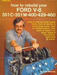
An engine identification tag is<br />
attached to the engine. The symbol<br />
code (Fig. I) identifies each engine<br />
for determining par:ts usage; i.e..<br />
en~ine cubic inch displacement and<br />
MODEL YEAR<br />
model year. The change level and<br />
engine code number determine if<br />
parts are peculiar to a specific<br />
engine. The engine plant code designates<br />
where and when the engine was<br />
built. It is imperitive that the codes on<br />
the engine identification tag be<br />
used when ordering parts or making<br />
inquiries about the engine. The<br />
pertinent codes are shown in the<br />
Master Parts Catalog to designate<br />
unique parts. (JANUARY) A2125.D<br />
FIG. 1-Enaine Identification Tag
8-2 GROUP 8-<strong>Engine</strong><br />
DIAGNOSIS AND TESTING<br />
DIAGNOSIS<br />
ENGINE<br />
On engines equipped with a<br />
Thermactor exhaust emission control<br />
system, disconnect the Thermactor<br />
system before performing engine<br />
diagnosis procedures. Disconnect<br />
the backfire suppressor valve vacuum<br />
sensing and air supply lines at<br />
the intake manifold connections. Plug<br />
the manifold connections to preclude<br />
leakage.<br />
<strong>Engine</strong> performance complaints<br />
usually fall under one <strong>of</strong> the basic<br />
headings listed in the Diagnosis<br />
Guide (Fig. 51). When a particular<br />
trouble can not be traced to a definite<br />
cause by a simple check, the possible<br />
items that could be at fault are listed<br />
in the order <strong>of</strong> their probable occurrence.<br />
Check the items in the order<br />
listed. For example, under Poor Acceleration,<br />
the ignition system is listed<br />
as a probable cause <strong>of</strong> the trouble. All<br />
the conventional ignition system items<br />
that affect acceleration are listed.<br />
Check all these items before proceeding<br />
to the next probable cause.<br />
IGNITION<br />
SYSTEM<br />
For diagnosis procedures <strong>of</strong> ignition<br />
system malfunctions, refer to<br />
Group 9.<br />
TESTING<br />
CAMSHAFT<br />
LOBE LIFT<br />
Check the lift <strong>of</strong> each lobe in<br />
consecutive order and make a note<br />
<strong>of</strong> the readings.<br />
I. Remove the air cleaner. Remove<br />
the heater hose and positive crankcase<br />
ventilation line from the rocker arm<br />
cover. Remove the valve rocker arm<br />
cover(s).<br />
2. On a 170 or 200 six or a 390<br />
V-8, remove the valve rocker arm<br />
shaft assemblies and install a solid<br />
tappet-type push rod in the push<br />
rod bore <strong>of</strong> the camshaft lobe to be<br />
checked or use the adapter for ballend<br />
push rods shown in Fig. 2.<br />
On a 289 V-8, remove the rocker<br />
arm stud nut, fulcrum seat and<br />
rocker arm. Use the adapter for<br />
ball-end push rods (Fig. 3).<br />
3. On a 427 V-8, if only one camshaft<br />
lobe is to be checked, loosen<br />
the lash adjusting screw. Slide the<br />
rocker arm assembly serving the<br />
camshaft lobe to be checked to one<br />
side. Secure it in this position with<br />
safety wire. To move the rocker<br />
arm on either end <strong>of</strong> the shaft, remove<br />
the retaining pin and washers,<br />
and slide the rocker arm <strong>of</strong>f the shaft.<br />
If an <strong>of</strong> the cam lobes are to be<br />
FIG. 2-Camshaft<br />
and 200 Six<br />
Lobe Lift-170<br />
FIG. 3-Camshaft lobe lift-289 V-8<br />
checked, remOfe the rocker arm<br />
shaft assembly(ies).<br />
4. Make sure the push rod is in<br />
the valve lifter socket. Install a dial<br />
indicator in such a manner as to<br />
have the ball socket adapter <strong>of</strong> the<br />
indicator on the end <strong>of</strong> the push<br />
rod and in the same plane as the<br />
push rod movement (Fig. 2 or 3).<br />
On a socket-type push rod, position<br />
the actuating point <strong>of</strong> the indicator<br />
in the push rod socket and in<br />
the same plane as the push rod<br />
movement (Fig. 2).<br />
5. Disconnect the brown lead<br />
(I terminal) and the red and blue<br />
lead (S terminal) at the starter<br />
relay. Install an auxiliary starter<br />
switch between the battery and S<br />
terminals <strong>of</strong> the starter relay. Crank<br />
the engine with the ignition switch<br />
OFF.<br />
Bump the crankshaft over until<br />
the tappet or liftel: is on the base<br />
circle <strong>of</strong> the camshaft lobe. At this<br />
point, the push rod will be in its<br />
lowest position.<br />
6. Zero the dial indicator. Continue<br />
to rotate the crankshaft slowly<br />
until the push rod is in the fully<br />
raised position.<br />
7. Compare the total lift recorded<br />
on the indicator with specifications.<br />
8. To check the accuracy <strong>of</strong> the<br />
original indicator reading, continue<br />
to rotate the crankshaft until the<br />
indicator reads zero. If the lift on<br />
any lobe is below specified wear<br />
limits, the camshaft and the valve<br />
lifters operating on the worn lobe(s)<br />
must be replaced.<br />
9. On a 170 or 200 six or a 390<br />
V -8, install the rocker arm shaft<br />
assemblies.<br />
On a 289 V -8, lubricate the rocker<br />
arm fulcrum seat area with Lubriplate,<br />
and install the rocker arm,<br />
fulcrum seat and stud nut. Adjust the<br />
valve clearance (Section 2).<br />
On a 289 high performance V-8,<br />
install the rocker arm, fulcrum seat<br />
and stud nut. Perform a preliminary<br />
valve lash adjustment.<br />
On a 427 V-8, position the valve<br />
rocker arm. If an end valve rocker<br />
arm was removed, slide it into position<br />
on the shaft and install the<br />
washers and retaining pin. Tighten the<br />
valve lash adjusting screw to hold the<br />
rocker arm and push rod in alignment.<br />
Adjust the valve lash on all<br />
rocker arms that had been moved out<br />
<strong>of</strong> position. Install the valve rocker<br />
arm cover(s) and partially tighten<br />
the retaining bolts. Operate the engine<br />
until normal operating temperature<br />
has been reached. Remove the valve<br />
rocker arm cover(s). Check and adjust<br />
the valve lash (Section 2).<br />
10. Install the valve rocker arm<br />
cover(s), hoses and the air cleaner.<br />
MANIFOLD VACUUM TEST<br />
A manifold vacuum test aids in<br />
determining the condition <strong>of</strong> an engine<br />
and in helping to locate the<br />
cause <strong>of</strong> poor engine performance.<br />
To check manifold vacuum:<br />
I. Operate the engine for a minimum<br />
<strong>of</strong> 30 minutes at 1200 rom
PART 8-1-General <strong>Engine</strong> Service 8-3<br />
Gauge Reading<br />
Refer to Part 8-5<br />
Low and steady.<br />
Very low<br />
Needle fluctuates steadily as<br />
speed increases.<br />
Gradual drop in reading at<br />
engine idle.<br />
Intermittent fluctuation.<br />
Slow fluctuation or drifting <strong>of</strong><br />
the needle.<br />
FIG. 4- Manifold Vacuum Gauge Readings<br />
or until the engine is at normal<br />
operating temperature.<br />
2. On 6-cylinder engines, install<br />
an accurate, sensitive vacuum gauge<br />
in the intake manifold fitting.<br />
On a V -8, engine, remove the plug<br />
or power brake line at the rear <strong>of</strong><br />
the intake manifold and install an<br />
accurate, sensitive vacuum gauge.<br />
3. Operate the engine at recommended<br />
idle rpm, with the transmission<br />
selector lever in neutral.<br />
4. Check the vacuum reading on<br />
the gauge.<br />
Test Conclusions<br />
Manifold vacuum is affected by<br />
carburetor adjustment, valve timing,<br />
ignition timing, the condition <strong>of</strong> the<br />
valves, cylinder compression, the condition<br />
<strong>of</strong> the positive crankcase ventilation<br />
system, and leakage <strong>of</strong> the<br />
manifold, carburetor, carburetor<br />
spacer or cylinder head gaskets.<br />
Because abnormal gauge readings<br />
may indicate that more than one <strong>of</strong><br />
the above factors are at fault, exercise<br />
caution in analyzing an abnormal<br />
reading. For example, if the<br />
vacuum is low, the correction <strong>of</strong> one<br />
item may increase the vacuum<br />
enough so as to indicate that the<br />
trouble has been corrected. It is important,<br />
therefore, that each cause<br />
EnQine Condition<br />
Normal engine idle manifold vacuum.<br />
Loss <strong>of</strong> power in all cylinders possibly<br />
caused by late ignition or valve<br />
timing, or loss <strong>of</strong> compression due to<br />
leakage around the piston rings.<br />
Intake mtlnifold, carburetor, spacer<br />
or cylinder head gasket leak.<br />
A partial or complete loss <strong>of</strong> power<br />
in one or more cylinders caused by a<br />
leaking valve, cylinder head or intake<br />
manifold gasket, a defect in the ignition<br />
system, or a weak valve spring.<br />
Excessive back pressure in the exhaust<br />
system.<br />
An occasional loss <strong>of</strong> power possibly<br />
caused by a defect in the ignition<br />
system or a sticking valve.<br />
Improper idle mixture adjustment<br />
or carburetor, spacer or intake manifold<br />
gasket leak or restricted crankcase-ventilation<br />
system.<br />
<strong>of</strong> an abnormal reading be illvestigated<br />
and further tcsts conducted,<br />
where necessary, in order to arrive<br />
at the correct diagnosis <strong>of</strong> the<br />
trouble.<br />
Fig. 4 lists various types <strong>of</strong> readings<br />
and their possible causes.<br />
Allowance should be made for the<br />
effect <strong>of</strong> altitude on the gauge reading.<br />
The engine vacuum will decrease<br />
with an increase in altitude.<br />
COMPRESSION TEST<br />
Dynamic Compression Test<br />
To perform a dynamic c6mpresthe<br />
procedures in<br />
sion check, follow<br />
Part 9-1, Section I under Ignition<br />
System Tests- Rotunda Testers.<br />
Compression Gauge Check<br />
1. Be sure the crankcase oil is at<br />
the proper level. Be sure the battery<br />
is fully charged. Operate the engine<br />
for a minimum <strong>of</strong> 30 minutes at<br />
1200 rpm or until the engine is at<br />
normal operating temperature. Turn<br />
the ignition switch <strong>of</strong>f, then remove<br />
all the spark plugs.<br />
2. Set the throttle plates (primary<br />
throttle plates only on a 4-barrel<br />
carburet.or) and choke plate in the<br />
wide open position.<br />
3. Install a compression gauge in<br />
No. I cylinder.<br />
4. Disconnect the brown lead<br />
(I terminal) and the red and blue<br />
lead (8 terminal) at the starter<br />
relay. Install an auxiliary starter<br />
switch between the battery and 8<br />
terminals <strong>of</strong> the starter relay. Using<br />
an auxiliary starter switch, crank the<br />
engine (with the ignition switch <strong>of</strong>f)<br />
a minimum <strong>of</strong> five pumping strokes,<br />
and record the highest reading.<br />
Note the number <strong>of</strong> compression<br />
strokes required to obtain the highest<br />
reading.<br />
5. Repeat the test on each cylinder,<br />
cranking the engine the same<br />
number <strong>of</strong> times for each cylinder<br />
as was required to obtain the highest<br />
reading on the No. I cylinder.<br />
Test Conclusions<br />
A variation <strong>of</strong> 20 psi from specified<br />
pressure is satisfactory. However, the<br />
compression <strong>of</strong> all cylinders should be<br />
uniform within 20 psi.<br />
A reading <strong>of</strong> more than the allowable<br />
tolerance above normal indicates<br />
excessive deposits in the cylinder<br />
or wrong cylinder head(s) on<br />
the engine.<br />
A reading <strong>of</strong> more than the allowable<br />
tolerance below normal indicates<br />
leakage at the cylinder head<br />
gasket, piston rings or valves or<br />
wrong cylinder head(s) on the engine.<br />
A low, even compression in two<br />
adjacent cylinders indicates a cylinder<br />
head gasket leak. This should be<br />
checked before condemning the<br />
rings or valves.<br />
To determine whether the rings or<br />
the valves are at fault, squirt the<br />
equivalent <strong>of</strong> a tablespoon <strong>of</strong> heavy<br />
oil into the combustion chamber.<br />
Crank the engine to distribute the<br />
oil and repeat the compression test.<br />
The oil will temporarily seal leakage<br />
past the rings. If approximately the<br />
same reading is obtained, the rings<br />
are satisfactory, but the valves are<br />
leaking. If the compression has increased<br />
substantially over the original<br />
reading, there is leakage past<br />
the rings.<br />
During a compression test, if the<br />
pressure fails to climb steadily and<br />
remains the same during the first<br />
two successive strokes, but climbs<br />
higher on the succeeding strokes, or<br />
fails to climb during the entire test,<br />
it indicates a sticking valve.<br />
HYDRAULIC VALVE<br />
LIFfER TESTS<br />
Dirt, deposits <strong>of</strong> gum and varnish<br />
and air bubbles in the lubricating oil
8-4 GROUP 8-<strong>Engine</strong><br />
FIG. 5-Placing<br />
lifter Plunger<br />
FIG. 6-Adjusting<br />
A1894-A<br />
Steel Ball in Valve<br />
- A1895-A -<br />
the Ram length<br />
can cause hydraulic valve lifter failure<br />
or malfunction.<br />
Dirt, gum and farnish can keep<br />
a check falfe from seating and<br />
cause a loss <strong>of</strong> hydraulic pressure.<br />
An open valve disc will cause the<br />
plunger to force oil back into the<br />
valve lifter reservoir during the time<br />
the push rod is being lifted to force<br />
the valve from its seat.<br />
Air bubbles in the lubricating system<br />
can be caused by too much oil<br />
in the system or too Iowan oil level.<br />
Air may also be drawn into the<br />
lubricating system through an opening<br />
in a damaged oil pick-up tube.<br />
Air in the hydraulic system can<br />
cause a loss <strong>of</strong> hydraulic pre~sure in<br />
the falfe lifter.<br />
ward. Pour hydraulic tester fluid<br />
into the cup to a level that will<br />
cover the valve lifter assembly. The<br />
fluid can be purchased from the<br />
manufacturer <strong>of</strong> the tester. Do not<br />
use kerosene or any other fluid, for<br />
they will not provide an accurate test.<br />
3. Plare a 5/l6-inch steel ball<br />
in the plunger cup (Fig. 5).<br />
4. Adjust the length <strong>of</strong> the ram<br />
so that the pointer is 1/16-inch<br />
below the starting mark when the<br />
ram contacts the valve lifter plunger<br />
(Fig. 6) to facilitate timing as<br />
the pointer passes the Start Timing<br />
Mark.<br />
Use the center mark on the pointer<br />
scale as the Stop Timing point<br />
instead <strong>of</strong> the origninal Stop Timing<br />
mark at the top <strong>of</strong> the scale.<br />
5. Work the valve lifter plunger<br />
up and down until the lifter fills<br />
with fluid and all traces <strong>of</strong> air bubbles<br />
have disappeared.<br />
6. Allow the ram and weight to<br />
force the valve lifter plunger downward.<br />
Measure the exact time it<br />
takes for the pointer to travel from<br />
the Start Timing to the Stop Timing<br />
marks <strong>of</strong> the tester.<br />
7. A valve lifter that is satisfactory<br />
must have a leak-down rate<br />
(time in seconds) within [he minimum<br />
and maximum limits specified.<br />
8. If the valve lifter is not within<br />
specifications, replace it with a new<br />
lifter.<br />
9. Remove the fluid from the cup<br />
and bleed the fluid from the lifter<br />
by depressing the plunger up and<br />
down. This step will aid in depressing<br />
the lifter plungers when<br />
checking the valve clearance.<br />
POSITIVE CRANKCASE<br />
VENTILATION SYSTEM TEST<br />
A malfunctioning positive crankcase<br />
ventilation system may be indicated<br />
by loping or rough engine<br />
idle. Do not attempt to compensate<br />
for this poor idle condition by disconnecting<br />
the crankcase ventilation<br />
system and/or making carburetor<br />
adjustments. The removal <strong>of</strong> the<br />
crankcase ventilation system from<br />
the engine will adversely affect the<br />
fuel economy and engine ventilation<br />
with resultant shortening <strong>of</strong> engine<br />
life.<br />
To determine whether the loping<br />
or rough idle condition is caused<br />
by a malfunctioning crallkcase ventilation<br />
system. perform either <strong>of</strong><br />
the following tests.<br />
Regulator Valve Test<br />
Assembled valve lifters can be<br />
tested with tool 6500-E to check the<br />
leak down rate. The leak down rate<br />
specification (Part 8-5) is the time<br />
in seconds for the plunger to move<br />
the length (Part 8-5) <strong>of</strong> its travel<br />
while under a 50 lb. load. Test the<br />
valve lifters as follows:<br />
1. Disassemble and clean the liter<br />
to remOfe all traces <strong>of</strong> engine<br />
oil. Lifters cannot be checked with<br />
engine oil in them. Only the testing<br />
fluid can be used.<br />
2. Place the valve lifter in the<br />
tester, with the plunger facing up- FIG. 7-AC Positive Crankcase Ventilation System Tester<br />
Install a known good regulator<br />
valve in the crankcase ventilation system.<br />
Start the engine and compare the<br />
engine idle condition to the prior<br />
idle condition.<br />
If the loping or rough idle condition<br />
remains when the good regulator<br />
valve is installed, the crankcase<br />
ventilation regulator valve is<br />
not at fault. Check the crankcase<br />
ventilation system for restriction at<br />
the intake manifold or carburetor<br />
spacer. If the system is not restricted,<br />
further engine component diagnosis<br />
will have to be conducted to<br />
find the malfunction.<br />
If the idle contition is found to<br />
be satisfactory, leave the new regulator<br />
valve installed and clean the<br />
hoses, fittings, etc.
PART 8-1-Genera\ <strong>Engine</strong> Service 8-5<br />
GREEN<br />
COLOR<br />
GREEN AND YELLOW<br />
YELLOW<br />
YELLOW AND RED<br />
RED<br />
FIG. 8-Diagnosis <strong>of</strong> Air Intake Test<br />
Air Intake Test<br />
This test uses the AC positive<br />
crankcase ventilation tester (Fig. 7)<br />
which is operated by engine vacuum<br />
through the oil filler opening. Follow<br />
the procedures described below to<br />
install the tester and check the crankcase<br />
ventilation system for faulty<br />
operation.<br />
1. With the engine at normal<br />
operating temperature, remove the<br />
oil filler cap and the dipstick.<br />
2. Connect one end <strong>of</strong> the hose<br />
to the tester body and connect the<br />
other end <strong>of</strong> the hose to the tester<br />
adapter.<br />
3. Use the dipstick hole plug to<br />
plug the opening in the dipstick<br />
tube.<br />
4. Insert the tester adapter in the<br />
filler cap opening and turn the selector<br />
knob (Fig. 7) to number 2<br />
for the 289, 390 and 427 V -8 or number<br />
4 for the 170 and 200 Six.<br />
5. Start the engine and let it idle.<br />
6. With the plugs secure, and<br />
the tube free <strong>of</strong> kinks, hold the<br />
tester body upright and note the<br />
color in the tester windows. Fig. 8<br />
lists the various colors and the<br />
probable cause or related condition<br />
<strong>of</strong> the crankcase ventilation system.<br />
7. Clean or replace the malfunctioning<br />
or defective components,<br />
CAUSE<br />
System operating properly<br />
Regulator valve or system partially<br />
plugged.<br />
Slight kink in tester hose.<br />
Slight engine blow-by.<br />
Plugs from the kit or the engine<br />
vacuum lines are not properly sealed.<br />
Tester knob improperly set.<br />
Regulator valve or system partially<br />
plugged.<br />
Tester hose kinked or blocked.<br />
Blow-by at maximum capacity <strong>of</strong><br />
regulator valve.<br />
Plugs from the kit or the engine<br />
vacuum lines are not properly sealed.<br />
Tester knob improperly set.<br />
Regulator valve or system partially<br />
or fully plugged.<br />
More engine blow-by than regulator<br />
valve can handle.<br />
Vent hose plugged or collapsed.<br />
Regulator valve or system fully<br />
plugged or stuck.<br />
Vent hose plugged or collapsed.<br />
Extreme blow-by.<br />
and repeat the test to ensure that<br />
the crankcase ventilation system is<br />
operating satisfactorily.<br />
THERMACTOR SYSTEM<br />
TESTS-BYP ASS TYPE<br />
BACKFIRE SUPPRESSOR<br />
VALVE<br />
The following procedures are recommended<br />
for checking and/or<br />
verifying that the various components<br />
<strong>of</strong> the Thermactor exhaust emission<br />
control system are operating properly.<br />
The engine and all components must<br />
be normal operating temperatures<br />
when the tests are performed. A preliminary<br />
"Diagnosis Guide" is included<br />
at the end <strong>of</strong> this Part (Fig.<br />
52) as an aid in trouble shooting the<br />
Thermactor exhaust emission control<br />
system.<br />
Prior to performing any extensive<br />
test or diagnosis <strong>of</strong> the Thermactor<br />
system, it must be determined<br />
that the engine as a unit is functioning<br />
properly. Disconnect the backfire<br />
suppressor valve vacuum sensing<br />
line at the intake manifold. Plug the<br />
manifold connection to preclude leakage.<br />
Normal engine diagnosis procedures<br />
can then be performed.<br />
Check Valve Test<br />
This test can be performed at the<br />
same time as the A ir Pump Test.<br />
1. Operate the engine until it<br />
reaches normal operating temperature.<br />
2. Inspect all hoses and hose connections<br />
for obvious leaks and correct<br />
as necessary before checking the<br />
check valve operation.<br />
3. Disconnect the air supply hose(s)<br />
at the check valve(s).<br />
4. Visual1y inspect the position <strong>of</strong><br />
the valve plate inside the valve body.<br />
It should be lightly positioned against<br />
the valve seat-away from the air<br />
manifold.<br />
5. Insert a probe into the hose connection<br />
on the check valve and depress<br />
the valve plate. It should freely return<br />
to the original position, against the<br />
valve seat, when released.<br />
If equipped with two check valve<br />
assemblies, check both valves for free<br />
operation.<br />
6. Leave the hose(s) disconnected<br />
and start the engine. Slowly increase<br />
the engine speed to 1500 rpm and watch<br />
for exhaust gas leakage at the check<br />
valve(s). There should not be any exhaust<br />
leakage. The valve may flutter<br />
or vibrate at idle speeds, but this is<br />
normal due to the exhaust pulsations<br />
in the manifold.<br />
7. If the check valve(s) does not<br />
meet the recommended conditions<br />
(steps 4,5 and 6), replace it.<br />
Backfire Suppressor Valve Air<br />
Leakage Test<br />
Air Gulp and Air Bypass Type Systems.<br />
With the backfire suppressor<br />
valve connected in the Themactor System,<br />
set the idle to the specified engine<br />
RPM and adjust the carburetor<br />
fuel air mixture screws (Part 10-1).<br />
If the idle remains rough or it is<br />
impossible to reduce the engine idle<br />
speed to the specified RPM, disconnect<br />
the following:<br />
Air Gulp System. Disconnect the<br />
vacuum sensing tube at the valve and<br />
plug the tube end.<br />
Disconnect the hose connecting the<br />
intake manifold to the backfire suppressor<br />
valve at the valve end and<br />
plug the hose.<br />
Air Bypass System. Disconnect the<br />
vacuum sensing tube at the valve and<br />
plug the tube end.<br />
If the idle can now be smoothed,<br />
or specified RPM achieved, the valve<br />
is defective. Replace the valve.<br />
If there is no difference in idle<br />
quality or RPM, reconnect the hose<br />
and line and check the induction system<br />
or base engine for other possible<br />
causes <strong>of</strong> poor idle quality or high<br />
idle RPM.
8-6 GROUP 8-<strong>Engine</strong><br />
Backfire Suppressor Valve<br />
Function Test<br />
ADAPTER FOR FUEL PUMP TEST GAUGE<br />
(CALIBRA TEO IN 1/4 PSI INCREMENTS)<br />
Air Gulp System.<br />
1. Disconnect the rubber hose connecting<br />
tbe air pump to the backfire<br />
suppressor valve at the valve. Make<br />
certain the hose leading to the intake<br />
manifold is free <strong>of</strong> kinks.<br />
2. Open and close the throttle rapidly.<br />
A loud sucking noise should be<br />
heard if the valve is functioning properly.<br />
3. If the sucking noise is not heard<br />
and the engine backfires through the<br />
exhaust system during deceleration,<br />
the backfire suppressor valve should<br />
be replaced.<br />
Air Bypass System.<br />
1. Disconnect the rubber hose connecting<br />
the backfire suppressor valve<br />
to the carburetor air cleaner or air<br />
supply pump air filter, at the valve<br />
end.<br />
2. Open and close the throttle rapidly;<br />
an escaping compressed air<br />
noise should be heard from the valve<br />
on rapid opening <strong>of</strong> the throttle and<br />
during deceleration. This is normal.<br />
3. If the compressed air noise is<br />
not heard during deceleration, the<br />
backfire suppressor valve should be<br />
replaced.<br />
11/32 INCH<br />
DIA. DRILL<br />
I<br />
I 1/2" PIPE PLUG<br />
1/2"PIPE TEE<br />
, PIPE SEA LER<br />
1/2" x 2" PIPE""- ~<br />
(THREADED ONE END ONLY)<br />
A2319-A<br />
FIG. 9-Air<br />
Gauge Adapter<br />
Supply Pump Test<br />
test gauge. The air pressure should<br />
be one (1) psi or more.<br />
8. If the air pressure does not<br />
meet or &lrpass the above pressures,<br />
disconnect and plug the air supply<br />
hose to the backfire suppressor valve.<br />
Clamp the plug in place, and repeat<br />
the pressure test.<br />
If the air pump pressure still<br />
doesn't meet the minimum requirement,<br />
install a new air pump filter<br />
element and repeat the pump test.<br />
Replace the air pump filter element<br />
and/or air pump as determined by<br />
the result <strong>of</strong> this test.<br />
CRANKSHAFT<br />
END PLAY<br />
FIG. 11<br />
Runout<br />
FIG. 13.<br />
Play<br />
. Typica I Flywheel Face<br />
Air Supply Pump Test<br />
--<br />
A2180-B<br />
1. Assemble a test gauge adapter<br />
as shown in Fig. 9,. and install a<br />
FIG. 72- Typical Flywheel Ring<br />
fuel pump test gaugt; on the adapter.<br />
Gear Runout<br />
The test gauge used must be accurate<br />
and readable in 1/4 psi increments.<br />
2. Operate the engine until it<br />
reaches normal operating temperature.<br />
A1398-B<br />
3. Inspect all hoses and hose connections<br />
for leaks and correct as nec-<br />
FIG. 10- Typical Crankshaft End<br />
essary before checking the air supply Play<br />
pump.<br />
4. Check the air pump belt tension<br />
and adjust to specifications.<br />
5. Disconnect the air supply<br />
hose(s) at the air manifold check<br />
valve(s). If there are two check<br />
valves, close <strong>of</strong>f one hose by inserting<br />
a suitable plug in the end <strong>of</strong> the<br />
hose. Use a hose clamp and secure<br />
the plug so it will not blowout.<br />
6. Insert the open pipe end <strong>of</strong> the<br />
test gauge adapter in the other air<br />
supply hose. Oamp the hose securely<br />
to the adapter to prefent it from<br />
blowing out.<br />
Position the adapter and test<br />
gauge so that the air blast emitted<br />
through the drilled pipe plug will be<br />
harmlessly dissipated. .<br />
7. Install a tachometer on the engine.<br />
Start the engine and slowly increase<br />
the engine !peed to 1500 rpm.<br />
Oh~rve the nre~~ure nroduced at the<br />
I. Force the crankshaft toward<br />
the rear <strong>of</strong> the engine.<br />
2. Install a dial indicator so that<br />
the contact point rests against the<br />
Typical Camshaft End<br />
crankshaft flange and the indicator<br />
axis is parallel to the crankshaft axis<br />
(Fig. 10).<br />
3. Zero the dial indicator. Push<br />
the crankshaft forward and note the<br />
reading on the dial.<br />
4. If the end play exceeds the<br />
wear limit, replace the thrust bearing.<br />
If the end play is less than<br />
the minimum limit. in!;nect the
PART 8-I-General <strong>Engine</strong> Service 8-7<br />
~ - -<br />
TAKE UP SLACK ON LEFT SIDE, ESTABLISH<br />
REFERENCE POINT. MEASURE DISTANCE A.<br />
TAKE UP SLACK ON RIGHT SIDE. FORCE<br />
LEFT SIDE OUT MEASURE DISTANCE 8.<br />
DEFLECTION IS A MINUS 8. A 1284-C<br />
FIG. 14- Typical Timing Chain<br />
Deflection<br />
thrust bearing faces for scratches,<br />
burrs, nicks or dirt. If the thrust<br />
faces are not defective or dirty, they<br />
probably were not aligned properly.<br />
Install the thrust bearing and align<br />
the faces following the procedure<br />
recommended under Main Bearing<br />
Replacement in the pertinent engine<br />
section. Check the crankshaft<br />
end play.<br />
FLYWHEEL FACE RVNOVT<br />
MAN VAL-SHIFT<br />
TRANSMISSIONS<br />
Install a dial indicator so that the<br />
indicator point bears against the flywheel<br />
face (Fig. 11). Turn the flywheel<br />
making sure that it is full forward<br />
or rearward so that crankshaft<br />
end play will not be indicated as flywheel<br />
runout.<br />
If the clutch face runout exceeds<br />
the specifications, remove the flywheel<br />
and c heck for burrs between<br />
the flywheel and the face <strong>of</strong> the<br />
crankshaft mounting flange. If no<br />
burrs exist, check the runout <strong>of</strong> the<br />
crankshaft mounting flange. Replace<br />
the flywheel or machine the crankshaft<br />
flywheel mounting face if the<br />
mounting flange runout is excessive.<br />
If the ring gear runout exceeds<br />
specifications, replace it or reinstall<br />
it on the flywheel, following the<br />
procedure under Ring Gear Replacement<br />
this part Section 2.<br />
FLYWHEEL RUNOUT-<br />
AUTOMATIC TRANSMISSION<br />
Remove the spark plugs.<br />
Install a dial indicator so that the<br />
indicator point rests on the face <strong>of</strong><br />
the ring gear adjacent to the gear<br />
teeth.<br />
Push the flywheel and crankshaft<br />
forward or backward as far as possible<br />
to prevent crankshaft end<br />
play from being indicated as flywheel<br />
runout.<br />
Set the indicator dial on the<br />
zero mark. Turn the flywheel one<br />
complete revolution while observing<br />
the total indicator reading (T.I.R.).<br />
If the T .I.R. exceeds specifications,<br />
the flywheel and ring gear assembly<br />
must be replaced.<br />
FLYWHEEL RING GEAR<br />
RUNOUT<br />
Install the dial indicator so that<br />
the point rests on a tooth <strong>of</strong> the<br />
ring gear (Fig. 12), and check the<br />
outside diameter (0.0.) <strong>of</strong> the<br />
assembled flywheel and ring gear.<br />
For this check, carefully adjust the<br />
indicator on the gear tooth so that<br />
the indicator point is near the extreme<br />
limit <strong>of</strong> its travel. This will<br />
prevent the indicator point from<br />
catching between the gear teeth as<br />
the flywheel is turned. Set the indicator<br />
dial on the zero mark and<br />
slowly turn the flywheel through one<br />
revolution while observing the total<br />
indicator reading. The T.I.R. must<br />
be within specifications, or the ring<br />
gear (standard transmission) or flywheel<br />
and ring gear assembly (automatic<br />
transmission) must be replaced.<br />
CAMSHAFT<br />
END PLAY<br />
On all V -8 engines, prying against<br />
the aluminum-nylon camshaft sprocket,<br />
with the valve train load on the<br />
camshaft, can break or damage the<br />
sprocket. Therefore, the rocker arm<br />
adjusting nuts must be backed <strong>of</strong>f, or<br />
the rocker arm and shaft assembly<br />
must be loosened sufficiently to free<br />
the camshaft. After checking the camshaft<br />
end play, adjust the valve clearance.<br />
Push the camshaft toward the rear<br />
<strong>of</strong> the engine. Install a dial indicator<br />
so that the indicator point is on the<br />
camshaft sprocket retaining ~crew<br />
(Fig. 13). Zero the dial indicator.<br />
Position a large screw driver between<br />
the camshaft sprocket and the block.<br />
Pull the camshaft forward and release<br />
it. Compare the dial indicator<br />
reading with specifications. If the<br />
end play is excessive, replace the<br />
thrust plate. Remove the dial indicator.<br />
TIMING<br />
CHAIN DEFLECTION<br />
1. Rotate the crankshaft in a<br />
clockwise direction (as viewed from<br />
the front) to take up the slack on<br />
the left side <strong>of</strong> the chain.<br />
2. Establish a reference point on<br />
the block and measure from this<br />
point to the chain (Fig. 14).<br />
3. Rotate the crankshaft in the<br />
opposite direction to take up the<br />
slack .on the right side <strong>of</strong> the chain.<br />
Force the left side <strong>of</strong> the chain out<br />
with the fingers and measure the distance<br />
between the reference point and<br />
the chain. The deflection is the difference<br />
between the two measurements.<br />
If the deflection exceeds specifications,<br />
replace the timing chain and<br />
sprockets.<br />
EJ<br />
ADJUSTMENTS<br />
COMMON ADJUSTMENTS AND REPAIRS<br />
VALVE CLEARANCE-<br />
HYDRAULIC VALVE LIFTERS,<br />
170 and 200 SIX<br />
A O.O60-inch shorter push rod or<br />
a O.O60-inch longer push rod are<br />
available for service to provide a<br />
means <strong>of</strong> compensating for dimen-<br />
sional changes in the valve mechanism.<br />
Refer to the Master Parts List<br />
or the specifications for the pertinent<br />
color code. Valve stem to valve<br />
rocker arm clearance should be to<br />
the specified clearance with the hydraulic<br />
lifter completely collapsed.<br />
Repeated valve reconditioning operations<br />
(valve and/or valve seat refacing)<br />
will decrease the clearance to<br />
the point that if not compensated<br />
for. the hydraulic valve lifter will<br />
cease to function.<br />
To determine whether a shorter<br />
or a longer push rod is necessary.<br />
make the following check:<br />
I. Disconnect the brown lead<br />
(I terminal) and the red and blue<br />
lead (8 terminal) at the starter relay.<br />
Install an auxiliary starter
8-8 GROUP 8-<strong>Engine</strong><br />
switch between the battery and S<br />
terminals <strong>of</strong> the starter relay. Crank<br />
the engine with the ignition switch<br />
OFF until the No.1 piston is on<br />
TDC after the compression stroke.<br />
By using the procedure in step 3,<br />
check the following valves:<br />
No. I Intake<br />
No.1 Exhaust<br />
No.2 Intake<br />
No.3 Exhaust<br />
No.4 Intake<br />
No.5 Exhaust<br />
2. Now rotate the crankshaft<br />
until the No.6 piston is on TDC<br />
after the compression stroke (I revolution<br />
<strong>of</strong> the crankshaft). By using<br />
the procedure in step 3, check the<br />
following valves:<br />
No.2 Exhaust<br />
No.3 Intake<br />
No.4 Exhaust<br />
No.5 Intake<br />
No.6 Intake<br />
No.6 Exhaust<br />
3. Using Tool-6Sl3-K apply pressure<br />
to the push rod end <strong>of</strong> the<br />
rocker arm (Fig. IS) to slowly bleed<br />
down the valve lifter until the<br />
plunger is completely bottomed.<br />
Hold the lifter in this position and<br />
check the available "clearance between<br />
the rocker arm and the valve<br />
stem tip with a feeler gauge.<br />
If the clearance is less than specifications,<br />
install an under size push<br />
rod. If the clearance is greater than<br />
specifications, install an oversize<br />
push rod.<br />
VALVE CLEARANCE-<br />
HYDRAULIC VALVE<br />
LIFTERS, 289 REGULAR V-8<br />
Two different procedures may be<br />
used to adjust the valve clearance<br />
on the 289 V -8 engine. The preferred<br />
procedure is recommended, but the<br />
alternate procedure may be used.<br />
Preferred Procedure<br />
The cylinders are numbered from<br />
Feeler Gauae Tool-6513 oK<br />
I'<br />
. I-SET NO.1 PISTON ON T.D.C. AT END OF<br />
CC».IPRESSION STROKE -ADJUST NO.1<br />
INTAKE AND EXHAUST<br />
ST,EP S-ADJUST NO.6 INTAKE AND EXHAUST<br />
STEP 2- ADJUST NO.5 INTAKE AND EXHAUST<br />
STEP 6-ADJUST NO.3 INTAKE AND EXHAUST<br />
"<br />
STEP 4-ADJUST NO.2 INTAKE AND EXHAUST<br />
STEP 8-ADJUST NO.81'1TAKE AND EXHAUST<br />
~. _." 3-ADJUST NO.4 INTAKE AND EXHAUST<br />
STEP 7-ADJUST NO.7 INTAKE AND EXHAUST<br />
..2198-..<br />
FIG. 16-289 V-8 Valve Clearance<br />
Adjustment Points<br />
front to rear-right bank, 1-2-3-4;<br />
left bank, 5-6-7-8.<br />
The valves on the right bank<br />
are arranged from front to rear,<br />
I-E-I-E-I-E-I-E.<br />
The valves on the left bank<br />
are arranged from front to rear,<br />
E-I-E-I-E-I-E-I.<br />
1. Disconnect the brown lead<br />
(I terminal) and the red and blue<br />
lead (S terminal) at the starter<br />
relay. Install an auxiliary starter<br />
switch between the battery and S<br />
terminals <strong>of</strong> the starter relay. Crank<br />
the engine with the ignition switch<br />
OFF.<br />
2. Make three chalk marks on<br />
the crankshaft damper (Fig. 16).<br />
Space the marks approximately<br />
900 apart so that with the timing<br />
mark, the damper is divided into<br />
four equal parts (900 represents 1/4<br />
<strong>of</strong> the distance around the damper<br />
circumference).<br />
3. Rotate the crankshaft until<br />
No. I piston is on TDC at the end<br />
<strong>of</strong> the compression stroke. Check<br />
the break-away torque (torque required<br />
to turn nut in a counterclockwise<br />
direction) <strong>of</strong> the No. I<br />
intake and exhaust stud nuts. Replace<br />
the stud nut if the break-away<br />
torque does not meet specifications.<br />
If the break-away torque still is not<br />
within specifications, replace the stud.<br />
4. With No. I piston on TDC at<br />
the end <strong>of</strong> the compression stroke,<br />
adjust the intake and exhaust valve<br />
clearance for No. I cylinder. Loosen<br />
FIG. 17- Typical Valve Clearance<br />
Adjustment-289 V-8<br />
FIG. 79-390 V-8 Valve<br />
Clearance<br />
the rocker arm stud nut until there<br />
is end clearance in the push rod,<br />
then tighten the nut to just remove<br />
all the push rod to rocker arm
clearance. This may be determined<br />
by rotating and/or moving the push<br />
rod with the fingers as the stud nut<br />
is tightened (Fig. 17). When the<br />
push rod to rocker arm clearance<br />
has been eliminated, tighten the stud<br />
nut an additional 3/4 turn to<br />
place the hydraulic lifter plunger in the<br />
desired operating range.<br />
S. Repeat this procedure for the<br />
remaining set <strong>of</strong> valves, turning the<br />
crankshaft with an auxiliary starter<br />
switch, 1/4 turn at a time, in the<br />
direction <strong>of</strong> rotation, while adjusting<br />
the valves in the firing order<br />
sequence. The firing order is<br />
1-5-4-2-6-3-7-8.<br />
An alternate method is to remove<br />
the distributor cap and turn the<br />
crankshaft with an auxiliary starter<br />
switch until the breaker points are<br />
on the next peak <strong>of</strong> the distributor<br />
cam lobe. When the breaker points<br />
are on the next distributor cam lobe,<br />
the valves for the cylinder next in<br />
the firing order can be adjusted.<br />
These procedures require two<br />
complete turns <strong>of</strong> the crankshaft.<br />
6. Operate the engine and check<br />
for rough engine idle or a noisy<br />
lifter(s). Valve clearance set too<br />
tight will cause rough engine idle,<br />
and valve clearance set too loose<br />
will cause a noisy lifter(s).<br />
Alternate Procedure<br />
Position the piston(s) on TDC<br />
after the compression stroke (See<br />
Step 2 above). Apply pressure to<br />
slowly bleed down the valve lifter<br />
until the plunger is completely bottomed<br />
(Fig. 18). While holding the<br />
valve lifter in the fully collapsed<br />
position, check the available clearance<br />
with a feeler gauge between<br />
the rocker arm and valve stem tip<br />
(Fig. 18). The feeler gauge width<br />
must not exceed 3/8-inch. If the<br />
clearance is not within specifications,<br />
rotate the rocker arm stud<br />
nut clockwise to decrease the clearance<br />
and counterclockwise to increase<br />
the clearance. Normally one<br />
turn <strong>of</strong> the rocker arm stud will vary<br />
the clearance by 0.006 inch:<br />
VALVE CLEARANCE-<br />
HYDRAULIC VALVE LIFTERS,<br />
390 V-8<br />
The valve arrangement is E-I-E-<br />
I-I-E-I-E from front to rear on both<br />
cylinder banks.<br />
A O.OOO-inch shorter push rod or<br />
a O.O60-inch longer push rod are<br />
available for servi.:e to provide a<br />
means <strong>of</strong> compensating for dimensional<br />
changes in the valve mechan-<br />
ism. Refer to the Master Parts List<br />
or the specifications for the pertinent<br />
color code.<br />
Valve stem to valve rocker arm<br />
clearance should be within specifications<br />
with the hydraulic lifter<br />
completely collapsed. Repeated valve<br />
reconditioning operations (valve and/or<br />
valve seat refacing) will decrease the<br />
clearance to the point that, if not<br />
compensated for, the hydraulic valve<br />
lifter will cease to function.<br />
To determine whether a shorter<br />
or a longer push rod is necessary,<br />
make the following check:<br />
1. Disconnect the brown lead<br />
(1 terminal) and the red and blue<br />
lead (8 terminal) at the starter relay.<br />
Install an auxiliary starter switch<br />
between the battery and S terminals<br />
<strong>of</strong> the starter relay. Crank the engine<br />
with the ignition switch OFF.<br />
2. Position the crankshaft as outlined<br />
in steps 3 and 4. Position the<br />
hydraulic lifter compressor tool on<br />
the rocker arm and slowly apply<br />
pressure to bleed down the hydraulic<br />
lifter until the plunger is completely<br />
bottomed (Fig. 19). Hold the<br />
lifter in the fully collapsed position<br />
and check the clearance between the<br />
valve stem and the rocker arm with<br />
a feeler gauge. If the clearance is<br />
within the specified limits (Part 8-5),<br />
a standard length push rod may be<br />
used. If the clearance is less than<br />
specified, replace the standard push<br />
rod with a shorter service push rod.<br />
If the clearance exceeds the specified<br />
amount, the operating range<br />
<strong>of</strong> the lifter is excessive, which indicates<br />
that the incorrect push rod has been<br />
installed or severe wear has occurred<br />
at the push rod ends, rocker arm, or<br />
valve stem. In this case, it will be<br />
necessary to determine the area <strong>of</strong><br />
discrepancy, and the incorrect or defective<br />
part(s) should be replaced. If<br />
all the valve train components except<br />
the push rod are within limits,<br />
install a O.060-inch longer push rod.<br />
3. Rotate the crankshaft until<br />
No. I piston is on TDC at the end<br />
<strong>of</strong> the compression stroke and check<br />
the following valves:<br />
No. I Intake No.1 Exhaust<br />
No.3 Intake No.4 Exhaust<br />
No.7 Intake No.5 Exhaust<br />
No.8 Intake No.8 Exhaust<br />
4. After these valves have been<br />
checked, rotate the crankshaft 3600<br />
(one revolution) to position No.6<br />
piston on TDC and check the following<br />
valves:<br />
No.2 Intake No.2 Exhaust<br />
No.4 Intake No.3 Exhaust<br />
No.5 Intake No.6 Exhaust<br />
No.6 Intake No.7 Exhaust<br />
When compressing the valve<br />
spring to remove the push rods, be<br />
sure the piston in the individual<br />
cylinder is below TDC to avoid<br />
contact between the valve and the<br />
piston.<br />
To replace a push rod, it will be<br />
necessary to remove the valve rocker<br />
arm shaft assembly, following<br />
the procedure in Part 8-4.<br />
Upon replacement <strong>of</strong> a valve<br />
push rod and/or valve rocker arm<br />
shaft assembly, the engine should<br />
not be cranked or rotated until the<br />
hydraulic lifters have had an opportunity<br />
to leak down to their<br />
normal operating position. The<br />
k:akdown rate can be accelerated<br />
by using the tool shown in Fig. 19<br />
on the valve rocker arm and applying<br />
pressure in a direction to collapse<br />
the lifter.<br />
VALVE LASH-MECHANICAL<br />
TAPPETS, 289 HIGH<br />
PERFORMANCEV-8<br />
It is important that the falfe lash<br />
be held to the correct specifications.<br />
If the lash is set too close, the valve<br />
will open too early and close too late,<br />
resulting in rough engine idle. Burning<br />
and warping <strong>of</strong> the valves will occur<br />
also because the valves cannot<br />
make firm contact with the seats long<br />
enough to cool properly. If the lash<br />
is excessive, it will cause the valve<br />
to open too late and close too early<br />
causing valve bounce. In addition,<br />
damage to the camshaft lobe is<br />
likely because the tappet foot will<br />
not follow the pattern <strong>of</strong> the camshaft<br />
lobe, causing a shock contact<br />
between these two parts.<br />
Preliminary<br />
(Cold)<br />
If the valve rocker arm(s) has<br />
been removed and installed, it will be<br />
necessary to make a preliminary<br />
(cold) valve lash adjustment before<br />
starting the engine. If the adjustment<br />
is made for an engine tune-up,<br />
follow the final (hot) adjustment procedure.<br />
1. Follow steps I thru 3 under<br />
Valve Clearance-Hydraulic Valve<br />
Lifters, 289 Regular V-8.<br />
2. With the No. I piston on TDC<br />
at the end <strong>of</strong> the compression<br />
stroke, adjust the intake and exhaust<br />
valve lash to the specified<br />
cold setting.<br />
3. Follow step 5 under Valve<br />
Clearance-Hydraulic Valve Lifters,<br />
289 Regular V -8.<br />
Final (Hot)<br />
1. Be sure the engine is at normal<br />
operating temperature before<br />
attempting to set the valve lash.
8-10<br />
GROUP 8-<strong>Engine</strong><br />
Step-Type Feeler Gouge<br />
A2053.B<br />
St~p- Type F;eler Gauge<br />
A1466-A<br />
FIG. 22-Valve Lash Adjustment-<br />
Mechanical Valve Lifters<br />
FIG. 20-Final Valve lash<br />
Adjustment-289 High<br />
Performance V-8<br />
the starter relay. Crank the engine<br />
with the ignition switch OFF.<br />
Rotate the crankshaft another<br />
2. With the engine idling, set the<br />
valve lash (Fig. 20) using a steptype<br />
feeler gauge only (GO and<br />
NO GO). The final (hot) intake and<br />
exhaust valve lash settings are listed<br />
in the Specification Section.<br />
For example, to obtain the correct<br />
setting if the valve lash is 0.019<br />
inch, use a step-type gauge <strong>of</strong> 0.018<br />
inch (GO) and 0.020 inch (NO<br />
GO). The GO step should enter,<br />
and the NO GO step should not<br />
enter. The resultant setting will be<br />
to the required setting (0.019 inch).<br />
VALVE LASH-MECHANICAL<br />
T APPETS-427 V-8<br />
It is important that the valve<br />
lash be held to the correct specifications.<br />
If the lash is set too close. the<br />
valve will open too early and close<br />
too late, resulting in rough engine<br />
idle. Burning and warping <strong>of</strong> the<br />
valves will occur also because the<br />
valves cannot make firm contact<br />
with the seats long enough to cool<br />
properly. If the lash is excessive,<br />
it will cause the valve to open too<br />
late and close too early causing<br />
valve bounce. In addition, damage<br />
to the camshaft lobe is likely because<br />
the tappet foot will not follow<br />
the pattern <strong>of</strong> the camshaft lobe,<br />
causing a shock contact between<br />
these two parts.<br />
Preliminary<br />
(Cold)<br />
If some component <strong>of</strong> the valve<br />
train has been replaced; i.e., rocker<br />
arm, push rod, camshaft, etc., it will<br />
be necessary to make a preliminary<br />
(cold) valve lash adjustment before<br />
starting the engine. If the valve lash<br />
adjustment is made for an engine<br />
tune-up, follow the final (hot) adjustment<br />
procedure.<br />
On V -8 engines the cylinders are<br />
numbered from front to rear-right<br />
bank, 1-2-3-4; left bank, 5-6-7-8.<br />
On the 427 V-8 engine, the valves<br />
are arranged from front to rear on<br />
both banks, E-I-E-I-I-E-I-E.<br />
1. Check the torque required to<br />
turn the screw. If the torque required<br />
to turn a screw is less than<br />
7 ft-lbs (84 in-Ibs), try an oversize<br />
self-locking adjusting screw. If this is<br />
still unsatisfactory, replace the rocker<br />
arm and adjusting screw.<br />
2. Disconnect the brown lead (I<br />
terminal) and the red and blue lead<br />
(8 terminal) at the starter relay. Install<br />
an auxiliary starter switch between<br />
the battery and 8 terminals <strong>of</strong><br />
3. On the 427 V-8 engine, make<br />
three chalk marks on the crankshaft<br />
damper (Fig. 21). Space the marks<br />
approximately 900 apart so that<br />
with the timing mark, the damper is<br />
divided into four equal parts (900<br />
represents 1/4 <strong>of</strong> the distance around<br />
the damper circumference). Set the<br />
intake and exhaust valve lash<br />
(Fig. 22) to specifications with a<br />
step-type feeler gauge (go and no<br />
go).<br />
Rotate the crankshaft until No. I<br />
piston is near TDC at the end <strong>of</strong> the<br />
compression stroke. Adjust the following<br />
valves:<br />
No. I Exhaust No. I Intake<br />
No.4 Exhaust No.7 Intake<br />
No.5 Exhaust No.8 Intake<br />
Rotate the crankshaft 1800 or<br />
1/2 turn in the direction shown in<br />
Fig. 21 (this puts No.4 piston on<br />
TDC). Adjust the following valves:<br />
No.2 Exhaust No.4 Intake<br />
No.6 Exhaust No.5 Intake<br />
3/4 turn in the same direction (this<br />
puts No 3 piston on TDC). Adjust<br />
the following valves:<br />
No.3 Exhaust<br />
No.7 Exhaust<br />
No.8 Exhaust<br />
Final<br />
STEP I-SET NO.1 PISTON ON T.D.C. AT END OF<br />
C~PRESSION STROKE-ADJUST NO. I,<br />
_.0. REPAIRS<br />
4, S, EXHAUST & 1':0. I, 8, 7, INTAKE.<br />
FIG. 21-Preliminary<br />
lash Adjustment<br />
Valve<br />
(Hot)<br />
No.2 Intake<br />
No.3 Intake<br />
No.6 Intake<br />
I. Be sure the engine is at normal<br />
operating temperature before attempting<br />
to set the valve lash.<br />
2. With the engine idling, set the<br />
valve lash (Fig. 22) using a steptype<br />
feeler gauge only (go and no<br />
go). The final (hot) intake and exhaust<br />
valve lash settings are listed<br />
in the Specifications (Part 8-5).<br />
For example, to obtain the correct<br />
setting if the valve lash is 0.025<br />
inch, use a step-type feeler gauge <strong>of</strong><br />
0.024 inch (go) and 0.026 inch<br />
(no go). The go step should enter,<br />
and the no go step should not enter.<br />
The resultant setting will be to the<br />
required setting (0.025 inch).<br />
VALVE ROCKER ARM<br />
AND/OR SHAFT ASSEMBLY<br />
Dress up minor surface defects<br />
on the rocker arm shaft and in the<br />
rocker arm bore with a hone.<br />
If the pad at the valve end <strong>of</strong><br />
the rocker arm has a grooved<br />
radius, replace the rockf"r arm. Do<br />
not attempt to true this surface<br />
by grinding.<br />
For a 289 V-8 engine, refer to<br />
Cylinder Head Repair for the rocker<br />
arm stud replacement procedure.<br />
PUSH RODS<br />
Following the precedures in Section<br />
3 under Push Rod Inspection<br />
check the push rods for straightness.<br />
If the runout exceeds the maximum<br />
limit at any point, discard the
PART 8-1-General<br />
<strong>Engine</strong> Service<br />
8-1<br />
rod. Do not attempt to straighten<br />
push rods.<br />
CYLINDER HEADS<br />
~~ ~'~ /ROCKER ARM<br />
~ STUD NUT<br />
~ 6A529<br />
Replace the head if it is cracked.<br />
Do not plane or grind more than<br />
0.010 inch from the cylinder head<br />
gasket surface. Remove all burrs or<br />
scratches with an oil stone.<br />
I<br />
FULCRUM<br />
SEAT<br />
6A528<br />
Rocker Arm Stud Nut<br />
Replacement-289 V-8<br />
If the rocker arm stud nut breakaway<br />
torque is less than specified,<br />
install a new standard stud nut and<br />
recheck the breakaway torque. Refer<br />
to Valve Clearance Adjustment<br />
for the torque procedure.<br />
FIG. 23-Rocker Arm Stud<br />
Removal<br />
Rocker Arm Stud<br />
Replacement-289 Regular V-8<br />
If it is necessary to remove a<br />
rocker arm stud, a rocker arm stud<br />
kit (tool T62F-6A527-B) is available<br />
which contains the following: a<br />
stud remover, a 0.OO6-inch a.s.<br />
reamer, and a 0.015-inch a.s. reamer.<br />
For 0.010 inch oversize studs,<br />
use reamer T66P-6A527-B. Use<br />
stud replacer T65P-6A527-A to<br />
press in replacement studs.<br />
Rocker arm studs that are broken<br />
or have damaged threads may be<br />
replaced with standard studs. Loose<br />
studs in the head may be replaced<br />
with 0.006, 0.010 or 0.015-inch<br />
oversize studs which are available for<br />
service.<br />
Standard and oversize studs can<br />
be identified by measuring the stud<br />
diameter within I 1/8 inch from the<br />
pilot end <strong>of</strong> the stud. The stud diameters<br />
are:<br />
Standard 0.3714-0.3721<br />
0.006 oversize...0.3774-0.378 I<br />
0.010 oversize...0.38 14--0.382 I<br />
0.015 oversize...0.3864-0.387 I<br />
When going from a standard size<br />
rocker arm stud to a 0.010 or 0.015-<br />
inch oversize stud, always use the<br />
0.006-inch oversize reamer before<br />
finish reaming with the 0.010 or<br />
0.0 l5-inch oversize reamer.<br />
I. Position the sleeve <strong>of</strong> the rocker<br />
arm stud remover (tool T62F-<br />
6A527-B) over the stud with the<br />
bearing end down. Thread the puller<br />
into the sleeve and over the stud<br />
until it is fully bottomed. Hold the<br />
sleeve with a wrench; then rotate the<br />
puller clockwise to remove the stud<br />
(Fig. 23).<br />
If the rocker arm stud was broken<br />
FIG. 25-Rocker Arm Stud<br />
Installation<br />
FIG. 26-Valve<br />
Stud Assembly<br />
Rocker Arm and<br />
<strong>of</strong>f flush with the stud boss. use an<br />
easy-out to remove the broken stud<br />
following the instructions <strong>of</strong> the tool<br />
manufacturer.<br />
2. If a loose rocker arm stud is<br />
being replaced. ream the stud bore<br />
using the proper reamer (or reamers<br />
in sequence) for the selected oversize<br />
stud (Fig. 24). Make sure the metal<br />
pa rtides do not cnter the fal fe area.<br />
3. Screw the new stud into the<br />
sliding driver <strong>of</strong> the rocker arm stud<br />
installer (tool T65 P-6A527-A) and<br />
coat the end <strong>of</strong> the stud with Lubriplate.<br />
Align the stud and installer<br />
with the stud bore; then tap the sliding<br />
driver until it bottoms (Fig. 25).<br />
When the installer contacts the stud<br />
boss, the stud is installed to its correct<br />
height.<br />
Valve Rocker Arm Stud<br />
Replacement-289 High<br />
Performance V-8<br />
The valve rocker arm and stud<br />
assembly is shown in Fig. 26.<br />
Removal<br />
I. Remove the air cleaner.<br />
2. Disconnect the spark plug<br />
wires at the spark plugs. Remove<br />
the wires from the bracket(s) on {fie
FIG. 27-<br />
FIG. 28.<br />
FIG. 29<br />
Reaming Valve Guides<br />
Valve Seat Refacing<br />
. Valve Seat Width<br />
rocker arm cover(s) and position the<br />
wires out <strong>of</strong> the way.<br />
3. If a rocker arm and stull is<br />
being removed from the right cylinder<br />
head, pull the regulator valve<br />
out <strong>of</strong> the rubber grommet and<br />
position the hose and valve out <strong>of</strong><br />
the way. Also remove the automatic<br />
choke heat tube.<br />
4. Remove the valve rocker arm<br />
cover(s)<br />
S. Remove the valve rocker arm<br />
stud nut, fulcrum seat, and rocker<br />
arm.<br />
6. Remove the rocker arm stud.<br />
Installation<br />
1. Apply light engine oil to the<br />
rocker arm stud threads (side that<br />
screws into the head only). Install the<br />
rocker arm stud and torque to specifications.<br />
2. Apply Lubriplate to the top<br />
<strong>of</strong> the valve stem and at the push<br />
rod guide in the cylinder head.<br />
3. Install the valve rocker arm,<br />
fulcrum seat, and stud nut. Perform<br />
a preliminary (cold) valve lash adjustment.<br />
4. Temporarily lay the valve<br />
rocker arm covers in place and connect<br />
the spark plug wire to the spark<br />
plugs. Operate the engine at 1200<br />
rpm for 30 minutes to stabilize engine<br />
temperatures. Remove the valve<br />
rocker arm covers and perform a hot<br />
valve lash adjustment with the engine<br />
idling.<br />
5. Clean the valve rocker arm<br />
cover(s) and the cylinder head gasket<br />
surface. Apply oil-resistant sealer<br />
to one side <strong>of</strong> a new cover gasket(s).<br />
Lay the cemented side <strong>of</strong> the gasket(s)<br />
in place in the cover(s).<br />
6. Position the cover(s) on the<br />
cylinder head(s). Make sure that the<br />
gasket seats evenly around the head.<br />
Install the valve cover bolts. Torque<br />
the bolts to specifications. Two<br />
minutes later, torque the bolts to<br />
the same specifications.<br />
If the right valve rocker arm<br />
cover was removed, install the automatic<br />
choke heat tube and the<br />
crankcase ventilation regulator valve.<br />
Reaming Valve Guides<br />
If it becomes necessary to ream<br />
a valve guide (Fig. 27) to install a<br />
valve with an oversize stem, a reaming<br />
kit is available which contains<br />
the following reamer and pilot combinations:<br />
a 0.OO3-inch O.S. reamer<br />
with a standard diameter pilot, a<br />
0.0 IS-inch O.S. reamer with a<br />
0.003-inch O.S. pilot, and a 0.030-<br />
inch reamer with a O.OIS-rnch O.S.<br />
pilot.<br />
When going from a standard size<br />
valve to an oversize valve. always<br />
use the reamers in sequence. Always<br />
reface the valve seat after the valve<br />
guide has been reamed, and use a<br />
suitable scraper to break the<br />
sharp corner (1.0.) at the top <strong>of</strong><br />
the valve 2uide.<br />
Refacing Valve Seats<br />
Refacing <strong>of</strong> the valve seats should<br />
be closely co-ordinated with refacing<br />
<strong>of</strong> the valve face so that the finished<br />
seat and valve face will be concentric<br />
and the specified interference fit<br />
will be maintained. This is important<br />
so that the valve and seat will have<br />
a compression tight fit. Be sure that<br />
the refacer grinding wheels are properly<br />
dressed.<br />
Grind the valve seats to a true 450<br />
angle (Fig. 28). Remove only enough<br />
stock to clean up pits, grooves, or to<br />
correct the valve seat runout. After<br />
the seat has been refaced, use a seat<br />
width scale to measure the seat<br />
width (Fig. 29). Narrow the seat, if<br />
necessary, to bring it within specifications.<br />
If the valve seat width exceeds<br />
the maximum limit, remove enough<br />
stock from the top edge and/or<br />
bottom edge <strong>of</strong> the seat to reduce<br />
the width to specifications (Fig. 28).<br />
Use a 30 0 angle grinding wheel<br />
to remove stock from the top <strong>of</strong> the<br />
seats (lower the seats) and use a 600<br />
angle wheel to remove stock from the<br />
bottom <strong>of</strong> the seats (raise the seats).<br />
The finished valve seat should contact<br />
the approximate center <strong>of</strong> the<br />
valve face. It is good practice to determine<br />
where the valve seat contacts<br />
the face. To do this, coat the seat<br />
with Prussian blue, then set the valve<br />
in place. Rotate the valve with .light<br />
pressure. If the blue is transferred to<br />
the center <strong>of</strong> the valve face, the contact<br />
is sa tisfactory. If the blue is transferred<br />
to the top edge <strong>of</strong> the valve<br />
face, lower the valve seat. If the blue<br />
is transferred to the bottom edge <strong>of</strong><br />
the valve face, raise the valve seat.<br />
VALVES<br />
For inspection procedures refer<br />
to Section 3.<br />
Valve defects, such as minor pits,<br />
grooves, etc., may be removed. Discard<br />
valves that are severely damaged,<br />
or if the face runout or stem<br />
clearance exceeds specifications.<br />
Refacing Valves<br />
The valve refacing operation<br />
should be closely co-ordinated with the
PART 8-1-General <strong>Engine</strong> Service<br />
8-13<br />
valve seat refacing operation so that<br />
the finished angles <strong>of</strong> the valve face<br />
and <strong>of</strong> the valve seat will provide a<br />
compression-tight fit. Be sure that the<br />
refacer grinding wheels are properly<br />
dressed.<br />
If the valve face run out is excessive<br />
and/or to remove pits and<br />
grooves, reface the valves to a true<br />
44 C angle. Remove only enough<br />
stock to correct the runout or to<br />
clean up the pits and grooves. I f the<br />
edge <strong>of</strong> the valve head is less than<br />
1/32 inch thick after grinding, replace<br />
the valve as the valve will run<br />
too hot in the engine. The interference<br />
fit <strong>of</strong> the valve and seat should<br />
not be la pped out.<br />
Remove all grooves or score<br />
marks from the end <strong>of</strong> the valve<br />
stem, and chamfer it as necessary.<br />
Do not remove more than 0.010<br />
inch from the end <strong>of</strong> the valve stem.<br />
The valve stem from the valve lock<br />
groove to the end (Fig. 39), must<br />
not be shorter than the minimum<br />
specified length.<br />
If the valve and/or valve seat has<br />
been ref aced, it will be necessary to<br />
check the clearance between the<br />
rocker arm pad and the valve stem<br />
with the valve train assembly installed<br />
in the en,gine.<br />
Select Fitting Valves<br />
If the valve stem to valve guide<br />
clearance exceeds the wear limit,<br />
ream the valve guide for the next<br />
oversize valve stem. Valves with oversize<br />
stem diameters <strong>of</strong> 0.003, 0.015 and<br />
0.030 inch are available for service.<br />
Always reface the valve seat<br />
after the valve guide has been<br />
reamed. Refer to Reaming Valve<br />
Guides.<br />
CAMSHAFT<br />
Remove light scuffs, scores or<br />
nicks from the camshaft machined<br />
surfaces with a smooth oil stone.<br />
CRANKSHAFf<br />
Dress minor imperfections with an<br />
oil stone. If the journals are severely<br />
marred or exceed the wear limit,<br />
they should be refinished to size for<br />
the next undersize bearing.<br />
Refinishing Journals<br />
Refinish the journal to give the<br />
proper clearance with the next undersize<br />
bearing. If the journal will not<br />
clean UD to give the proper clearance<br />
with the maximum undersize bearing<br />
available, replace the crankshaft.<br />
Always reproduce the same journal<br />
shoulder radius that existed<br />
originally. Too small a radius will<br />
result in fatigue failure <strong>of</strong> the crankshaft.<br />
Too large a radius will result<br />
in bearing failure due to radius ride<br />
<strong>of</strong> the bearing.<br />
After refinishing the journals,<br />
chamfer the oil holes, then polish<br />
the journal with a No. 320 grit<br />
polishing cloth and engine oil. Crocus<br />
cloth may be used also as a<br />
polishing agent.<br />
PISTONS. PINS AND RINGS<br />
Fitting Pistons<br />
Pistons are available for service<br />
in standard sizes and the oversizes<br />
shown in Fig. 30.<br />
The standard-size pistons are<br />
color coded red or blue on the<br />
dome. Refer to the specifications<br />
for the standard-size piston dimensions.<br />
Pi ston pins and retainers are<br />
provided with new pistons, except<br />
retainers are not used an the 170<br />
and 200 Six and 289 V-8.<br />
Follow the procedures in Section<br />
3 to measure the piston 0.0. and<br />
cylinder bore 1.0. The dimensions<br />
should be within specifications, and<br />
the piston to bore clearance (bore<br />
1.0. minus piston 0.'0.) must be<br />
within the specified limits.<br />
If the clearance is greater than the<br />
maximum limit, recheck calculations<br />
to be sure that the proper size piston<br />
has been selected, check for a damaged<br />
piston; then, try a new piston.<br />
If the clearance is less than the<br />
minimum limit, recheck calculations<br />
before trying another piston. If none<br />
can be fitted, refinish the cylinder to<br />
provide the proper clearance for the<br />
piston.<br />
When a piston has been fitted,<br />
mark it for assembly in the cylinder<br />
to which it was fitted.<br />
If the taper, out-<strong>of</strong>-round and<br />
piston to cylinder bore clearance<br />
conditions <strong>of</strong> the cylinder bore are<br />
within specified limits, new piston<br />
rings wi II give satisfactory service.<br />
If the new rings are to be installed<br />
in a used cylinder that has not been<br />
refinished, remove the cylinder wall<br />
glaze. Be sure to clean the cylinder<br />
bore thoroughly, following the procedure<br />
in Section 3.<br />
To Fit a Piston:<br />
1. Calculate the size piston to be<br />
used by taking a cylinder bore<br />
check. Follow the procedures outlined<br />
in Section 3.<br />
2. Select the proper size piston<br />
to provide the desired clearance<br />
(refer to the specifications). Measure<br />
the piston diameter in line with the<br />
centerline <strong>of</strong> the piston pin and at<br />
90 0 to the piston pin axis.<br />
3. Make sure the piston and cylinder<br />
block are at room temperature<br />
(700 F). After any refinishing<br />
operation, allow the cylinder bore<br />
to cool and make sure the piston<br />
and bore are clean and dry before<br />
the piston fit is checked.<br />
<strong>Engine</strong><br />
200 Six<br />
289,390 V-8<br />
(2-V and 4-V)<br />
I 289 High<br />
I P--';rf~~~-~nce<br />
V-8<br />
427 V-8<br />
FIG. 30.<br />
Piston<br />
Oversize<br />
(inches)<br />
0.003, 0.020,<br />
0.030, 0.040<br />
Standard Only<br />
Standard Only<br />
Oversi ze Service Pistons<br />
Fitting Piston Rings<br />
I. Select the proper ring set for<br />
the size piston to be used.<br />
2. Position the ring in the cylinder<br />
bore in which it is going to be used.<br />
3. Push the ring down into the<br />
bore area where normal ring wear is<br />
not encountered.<br />
4. Use the head <strong>of</strong> a piston to<br />
position the ring in the bore so that<br />
the ring is square with the cylinder<br />
wall. Use caution to avoid damage<br />
to the ring or cylinder bore.<br />
5. Measure the gap between the<br />
ends <strong>of</strong> the ring with a feeler gauge<br />
(Fig. 31). If the ring gap is less or<br />
greater than the specified limits,<br />
try another ring set.<br />
6. Check the ring side clearance<br />
<strong>of</strong> the compression rings with a<br />
feeler gauge inserted between the ring<br />
and its lower land (Fig. 32). The<br />
ga uge should slide freely around the<br />
entire ring circumference without<br />
binding. Any wear that occurs will<br />
form a step at the inner portion <strong>of</strong><br />
the lower land. If the lower lands<br />
ha ve high steps, the piston should<br />
be replaced.
8-14 GROUP 8-<strong>Engine</strong><br />
expand the reamer slightly and make<br />
another cut. Repeat the procedure<br />
until the proper fit is obtained.<br />
Check the piston pin for fit in the<br />
respective rod or rod bushing if necessary,<br />
ream or hone the rod bushing to fit<br />
the pin to specifications.<br />
THERMACTOR AIR<br />
SUPPL Y PUMP<br />
The air supply pump and compon.<br />
ent parts are shown in Fig. 33.<br />
Disassembly<br />
1. Position the air supply pump<br />
in a vise with the pulley hub between<br />
the vise jaws and the pump assembly<br />
above the vise. Do not mount the<br />
pump housing in a ~ise.<br />
2. Remove the cover bolts. Use a<br />
plastic (or rawhide) hammer to tap<br />
the cover assembly <strong>of</strong>f the dowel<br />
pins. Then pull the cover assembly <strong>of</strong>f<br />
the pump by hand.<br />
3. Remove the rotor ring screws<br />
~<br />
Fitting Piston Pins<br />
On the 390 or 427 V-8, the piston<br />
pin should be a light thumb press<br />
fit at normal temperature (700 F).<br />
Standard piston pins are color coded<br />
green. Pins <strong>of</strong> O.OOI-inch oversize<br />
(color coded blue) and 0.002-inch<br />
oversize (color coded yellow) are<br />
available.<br />
Install the piston pin in the piston<br />
and rod. Install a new retainer at<br />
each end <strong>of</strong> the pin to hold it in<br />
place. Make sure the retainers are<br />
properly seated in their grooves.<br />
On the 170 and 200 Six or 289<br />
V -8, install the piston pin, following<br />
the procedure under Piston Assembly<br />
(Part 8-2 or 8-3).<br />
If the pin hole in the piston must<br />
be reamed or honed use precision honing<br />
equipment or an expansion-type<br />
piloted reamer. Piston pin bores must<br />
not be reamed with hand-driven reamers.<br />
Use motor-driven reamers, but do<br />
not exceed the cutting speed (rpm)<br />
recommended by the reamer manufacturer.<br />
If a reamer is used, set the reamer<br />
to the size <strong>of</strong> the pin bore; then<br />
expand the reamer slightly and trial<br />
ream the pin bore. Take a light cut.<br />
Use a pilot sleeve <strong>of</strong> the nearest<br />
size to maintain alignment <strong>of</strong> the<br />
bores.<br />
Check the hole size, using the<br />
new piston pin. If the bore is small,<br />
:OVERA~~M6LY<br />
96418<br />
~<br />
~<br />
~<br />
i<br />
COVER BOLTS<br />
ROTOR RING SCREWS<br />
375004.S<br />
-~<br />
~<br />
~<br />
BEARING<br />
9B477<br />
I<br />
ROTOR RING<br />
.<br />
VANE SHAFT<br />
VANE AND BEARfNG'ASSEM~LY'<br />
9B474 ( ONE REQUIRED)<br />
98482 (TWO REQUIRED)<br />
REAR SEAL<br />
~ ~<br />
-..,<br />
~,J ..<br />
U-<br />
=~~,%iC<br />
SHOE SPRING<br />
98476<br />
. COR<br />
CARBON SHOES-9B475<br />
FIG. 33- Thermactor System Air Supply Pump-<br />
CQI.\PRESSION CHAMBER<br />
J""<br />
FIG. 34-<br />
~ ..' \: ~<br />
'ANE<br />
SHOE SPR,NG<br />
CARBON<br />
SHOES<br />
~<br />
~<br />
~<br />
SMALL rOWEL<br />
"""--, - -.,.,. \<br />
;:-2::'~';;;;;:"<br />
'\--,<br />
Ti! "'"<br />
1"~<br />
LARGE DOWEL<br />
RELIEF Vj..~VE.tAI<br />
c ,<br />
RELIEF<br />
VALVE<br />
96479<br />
HOUSING<br />
Exploded View<br />
INTAKE<br />
CHAMBER<br />
PULLEY HUB<br />
A2307.A<br />
/<br />
t<br />
NARRON :iIDE DF SHDI<br />
I<br />
HOUSING<br />
,<br />
EXHAUST CHAMBER<br />
RELIEF VALVE<br />
Vanes, Carbon Shoes and Springs Installed in Rotor<br />
"RIPPER<br />
A230B-A
PART 8-1-General <strong>Engine</strong> Service 8-15<br />
and remove the rotor ring and bearing<br />
assembly. Remove the rear seal.<br />
This is a carbon seal and it should<br />
be replaced whenever the pump is<br />
disassembled.<br />
4. Locate the vane (Fig. 34) that<br />
is attached to the bearing nearest the<br />
cover assembly (rear <strong>of</strong> pump). Grasp<br />
it with the fingers and pull it as far as<br />
possible out <strong>of</strong> the rotor. Then pull<br />
the other vanes out as far as possible.<br />
Alternately pull each vane until they<br />
are free <strong>of</strong> the rotor. If the carbon<br />
shoes and shoe springs move out <strong>of</strong><br />
the rotor as the vanes are being removed,<br />
push down on the carbon<br />
shoe next to the shoe spring. Then<br />
remove the shoe spring. This will aid<br />
in removal <strong>of</strong> the vanes.<br />
5. Use a pair <strong>of</strong> tweezers to remove<br />
the carbon shoes. If needle-nosed pliers<br />
are used to remove the carbon shoes~<br />
do not pinch the shoes with the pliers<br />
too tightly as the carbon is easily<br />
crushed.<br />
6. If the bearing in the rotor ring<br />
requires replacement, position- the<br />
rotor ring on Tool T66L-9A486-AB<br />
with the bearing part number facing<br />
upwards. Place Tool T66L-9A486-AA<br />
on the bearing and use an arbor press<br />
to remove the bearing.<br />
Further disassembly <strong>of</strong> the rotor<br />
from the housing is not recommended.<br />
If any components <strong>of</strong> the housing<br />
assembly require replacement, the entire<br />
housing must be replaced.<br />
Cleaning and Inspection<br />
Refer to Section 3 for the cleaning<br />
md inspection procedures.<br />
Assembly<br />
1. The rotor ring is a matched<br />
assembly with the housing and rotor<br />
assembly, thus these parts are replaceable<br />
as a unit only. If the rotor<br />
ring bearing was removed, use Tools<br />
T66L-9A486-AA and T66L-9A486-AB<br />
and press a new bearing into the rotor<br />
ring. The part number side <strong>of</strong> the<br />
bearing should be on the same side <strong>of</strong><br />
the rotor ring as the flat surface (side<br />
towards rotor), and the bearing should<br />
be flush to 1/32 inch below the surface<br />
<strong>of</strong> the ring.<br />
2. Place the rotor and housing assembly<br />
in a vise with the vise jaws<br />
gripping the pulley hub. Do not clamp<br />
the housing assembly in a ~ise.<br />
3. Lubricate the ~ane assembly<br />
bearings with only the special air<br />
pump bearing lubricant (refer to<br />
Group 21 for the lube specification)<br />
as follows:<br />
Hold each vane assembly bearing<br />
over the vane assembly pin (Tool-<br />
T66L-9A486-C) with the pin just engaged<br />
in the bearing. Fill the inside<br />
<strong>of</strong> the bearing with bearing lubricant.<br />
Cover the open end <strong>of</strong> the<br />
bearing with the thumb or finger,<br />
and press the bearing onto the assembly<br />
pin. This will force the lubricant<br />
into and around the needle rollers<br />
<strong>of</strong> the bearing. Wipe <strong>of</strong>f the excess<br />
grease. Repeat the procedure for the<br />
other vane bearings.<br />
4. Mesh the bearings <strong>of</strong> the vane<br />
assemblies so that the ends <strong>of</strong> the<br />
vanes are even, and install the vanes<br />
in the rotor (Fig. 34).<br />
5. Install the carbon shoes in the<br />
rotor. One side <strong>of</strong> each shoe is not<br />
square with the other sides. The shoes<br />
must be installed with the narrow<br />
edge towards the vane bearings as<br />
shown in Fig. 34 and the slant side<br />
against the vane.<br />
6. Install the shoe springs between<br />
the rotor and shoe in front <strong>of</strong> the<br />
leading (counterclockwise rotation<br />
from rear <strong>of</strong> pump) face <strong>of</strong> each vane.<br />
The springs must be installed with the<br />
tension at the ends <strong>of</strong> the spring<br />
against the rotor and the tension at<br />
the center <strong>of</strong> the spring against the<br />
shoe.<br />
Position the vanes with one vane<br />
against the stripper part <strong>of</strong> the housing<br />
as shown in Fig. 34.<br />
7. Lubricate the rotor rear bearing<br />
(in the rotor ring) with air pump<br />
lubricant (refer to Group 21 for the<br />
specification). Coat the bearing surfaces<br />
with lubricant and work it into<br />
the bearing with the thumb or finger.<br />
Wipe the excess lubricant from the<br />
bearing and rotor ring assembly.<br />
8. Position a new rear seal and<br />
the rotor ring and bearing assembly<br />
on the rotor. The rotor ring bolt holes<br />
are unevenly spaced to ensure the rotor<br />
ring being properly aligned with<br />
the rotor. Apply a thin coating <strong>of</strong><br />
Loctite thread locking compound to<br />
the rotor ring attaching screws, and<br />
install the ring screws and torque to<br />
specifications.<br />
9. Using the vane assembly pin<br />
(T66L-9A486-C), align the vane bearings.<br />
Remove the alignment tool.<br />
10. Carefully align the cover assembly<br />
with the rotor and insert the vane<br />
shaft into the vane bearings. Do not<br />
force the shaft into place, or the vanes<br />
will become misaligned. It may be<br />
necessary to rotate the cover and shaft<br />
and/or wiggle it slightly from side to<br />
side while pushing inward.<br />
Rotate the cover to align with the<br />
housing dowels, and push it onto the<br />
dowels.<br />
11. Install the cover bolts and<br />
torque e~nly and alternately in sequence<br />
to specifications.<br />
THERMACfO R RELIEF<br />
V ALVE REPLACEMENT<br />
Do not disassemble the air pump<br />
to replace the relief ~al~e. but remo~e<br />
it from the engine.<br />
I. Position Tool T66L-9A486-D on<br />
the air pump and remove the relief<br />
valve with the aid <strong>of</strong> a slide hammer<br />
(T59L-IOO-B).<br />
2. Position the relief valve on the<br />
pump housing and hold Tool T66L-<br />
9A486-B on the relief valve. Use a<br />
hammer to tap the tool lightly until<br />
the relief valve is seated.<br />
CYLINDER BLOCK<br />
Refinishing Cylinder Walls<br />
Honing is recommended for refinishing<br />
cylinder walls only when the<br />
walls have minor imperfections, such<br />
as light scuffs and scratches, or for<br />
fitting pistons to the specified clearance.<br />
The grade <strong>of</strong> hone to be used<br />
is determined by the amount <strong>of</strong><br />
metal to be removed. Follow the instructions<br />
<strong>of</strong> the hone manufacturer.<br />
If coarse stones are used to start the<br />
honing operation, leave enough material<br />
so that all hone marks can be<br />
removed with the finishing hone<br />
which is used to obtain the proper<br />
piston clearance.<br />
Cylinder walls that are severely<br />
marred and/or worn beyond the<br />
specified limits should be refinished.<br />
Before any cylinder is refinished, all<br />
main bearing caps must be in place<br />
and tightened to the proper torque<br />
so that the crankshaft bearing bores<br />
will not become distorted from the<br />
refinishing operation.<br />
Refinish only the cylinder or cylinders<br />
that require it. All pistons are<br />
the same weight, both standard and<br />
oversize; therefore, various sizes <strong>of</strong><br />
pistons can be used without upsetting<br />
engine balance.<br />
Refinish the cylinder with the<br />
most wear first to determine the<br />
maximum oversize. If the cylinder<br />
will not clean up when refinished<br />
for the maximum oversize piston<br />
recommended, replace the cylinder<br />
block.<br />
Refinish the cylinder to within approximately<br />
0.0015 inch <strong>of</strong> the required<br />
oversize diameter. This will<br />
allow enough stock for the final step<br />
<strong>of</strong> honing so that the correct surface<br />
finish and pattern are obtained.<br />
For the proper use <strong>of</strong> the refinishing<br />
equipment follow the instructions <strong>of</strong><br />
the manufacturer. Only experienced<br />
personnel should be allowed to perform<br />
this work.<br />
Use a motor-driven, spring-pressure-type<br />
hone at a speed <strong>of</strong> 300-500
8-16<br />
GROUP 8-<strong>Engine</strong><br />
SHADED AREAS MAY BE REPAIRED WITH EPOXY<br />
The following procedure should be<br />
used to repair porous areas or sand<br />
holes in cast iron.<br />
FRONT AND LEFT SIDE<br />
TYPICAL FOR 6-CYLINDER ENGINE<br />
FRONT AND LEFT SIDE<br />
TYPICAL FOR V.8 ENGINE<br />
I. Clean the surface to be repaired<br />
by grinding or rotary filing to a<br />
clean bright metal surface. Chamfer<br />
or undercut the hole or porosity to a<br />
greater depth than the rest <strong>of</strong> the<br />
cleaned surface. Solid metal must<br />
surround the hole. Openings larger<br />
than 1/4 inch should not be repaired<br />
using metallic plastic. Openings<br />
in excess <strong>of</strong> 1/4 inch can be<br />
drilled, tapped and plugged using<br />
common tools. Clean the repair area<br />
thoroughly. Metallic p.lastic will not<br />
stick to a dirty or oil surface.<br />
REAR AND RIGHT SIDE<br />
REAR AND RIGHT SIDE<br />
FIG. 35- Typical Cast Iron Cylinder Block Areas Repairable with Metallic<br />
Plastic<br />
rpm. Hones <strong>of</strong> grit sizes 180-220 will<br />
normally provide the desired bore surface<br />
finish <strong>of</strong> 15/32 RMS. When honing<br />
the cylinder bores use a lubricant<br />
mixture <strong>of</strong> equal parts <strong>of</strong> kerosene and<br />
SAE No. 20 motor oil. Operate the<br />
hone in such a way to produce a crosshatch<br />
finish on the cylinder bore. The<br />
cross hatch pattern should be at an<br />
angle <strong>of</strong> approximately 30 0 to the<br />
cylinder bore. After the final operation<br />
in either <strong>of</strong> the two refinishing methods<br />
described and prior to checking the<br />
piston fit, thoroughly clean and oil<br />
the cylinder walls. following the<br />
procedure in Section 3. Check the<br />
piston fit, following the procedure<br />
in this section and Section 3. Mark<br />
the pistons to correspond to the<br />
cylinders in which they are to be<br />
installed. When the refinishing <strong>of</strong><br />
all cylinders that require it has been<br />
completed and all pistons are fitted,<br />
thoroughly clean the entire block<br />
and oil the cylinder walls following<br />
the procedure under Cylinder Block<br />
Cleaning in Section 3.<br />
REPAIRING ENGINE<br />
CASTINGS WITH SAND<br />
HOLEIS) OR POROSITY<br />
Porosity or sand hole(s) which will<br />
.J CLEANING AND INSPECTION<br />
VALVE ROCKER ARM<br />
AND/OR SHAFT ASSEMBLY<br />
CLEANING<br />
Clean all the parts thoroughly.<br />
A2386-B<br />
cause oil seepage or leakage can<br />
occur with modern casting processes.<br />
A complete inspection <strong>of</strong> engine and<br />
transmission should be made. If the<br />
leak is attributed to the porous condition<br />
<strong>of</strong> the engine block or sand<br />
hole(s) repairs can be made with<br />
metallic plastic (part No. C6AZ-19554-<br />
A). Do not repair cracks with this material.<br />
Repairs with this metallic plastic<br />
must be confined to those cast iron<br />
engine component surfaces (Fig. 35)<br />
where the inner wall surface is not<br />
exposed to engine coolant pressure or<br />
oil pressure, for example:<br />
I. Cylinder block surfaces extending<br />
along the length <strong>of</strong> the block, upward<br />
from the oil pan rail to the cylinder<br />
water jacket but not including<br />
machined areas.<br />
2. Lower rear face <strong>of</strong> the cylinder<br />
block.<br />
3. Intake manifold casting. Repairs<br />
are not recommended to the intake<br />
manifold exhaust crossover section,<br />
since temperatures can exceed<br />
the recommended temperature limit <strong>of</strong><br />
5000 F.<br />
\<br />
4. Cylinder front cover on engines<br />
using cast iron material.<br />
5. Cy'linder head, along the rocker<br />
arm cover gasket surface.<br />
Make sure all oil passages are open.<br />
On ball. stud rock.er arms, make<br />
sure the 011 passage In the push rod<br />
end <strong>of</strong> the rocker arm is open.<br />
2. Mix the metallic plastic base<br />
and hardener as directed on the container.<br />
Stir thoroughly until uniform.<br />
3. Apply the repair mixture with a<br />
suitable clean tool. (putty knife, wood<br />
spoon, etc.) forcing the epoxy into the<br />
hole or porosity.<br />
4. Allow the repair mixture to harden.<br />
This can be accomplished by two<br />
methods-heat cure with a 2500 watt<br />
lamp placed 10 inches from the repaired<br />
surface, or air dry for 10-12<br />
hours at temperatures above 500 F.<br />
5. Sand or grind the repaired<br />
area to blend with the general contour<br />
<strong>of</strong> the surrounding surface.<br />
6. Paint the surface to match the<br />
rest <strong>of</strong> the block.<br />
FLYWHEEL RING GEAR-<br />
MANUAL-SHIFT<br />
TRANSMISSIONS<br />
To replace a defective ring gear.<br />
heat the defective ring gear with a<br />
blow torch on the engine side <strong>of</strong> the<br />
gear, and knock it <strong>of</strong>f the flywheel.<br />
Do not hit the flywheel when removing<br />
the ring gear.<br />
Heat the new ring gear evenly<br />
until the gear expands enough to<br />
slip onto the flywheel. Make sure<br />
the gear is seated properly against<br />
the shoulder. Do not heat any portion<br />
<strong>of</strong> the gear to a temperature<br />
higher than 500 0 F. If this limit is<br />
exceeded, the temper will be removed<br />
from the ring gear teeth.<br />
INSPECTION<br />
On rocker arm shaft assemblies,<br />
check the clearance between each
PART 8-1-General <strong>Engine</strong> Service 8.17<br />
rocker arm and the shaft by checking<br />
the 10 <strong>of</strong> the rocker arm bore<br />
and the 00 <strong>of</strong> the shaft. If the clearance<br />
between any rocker arm and<br />
the shaft exceeds the wear limit, replace<br />
the shaft and/or the rocker<br />
arm. Inspect the shaft and the rocker<br />
arm bore for nicks, scratches, scores<br />
or scuffs.<br />
Inspect the pad at the valve end<br />
<strong>of</strong> the rocker arm for indications <strong>of</strong><br />
scuffing or abnormal wear. If the<br />
pad is grooved, replace the rocker<br />
arm. Do not attempt to true this surface<br />
by grinding.<br />
On ball stud rocker arms, check<br />
the rocker arm and fulcrum seat for<br />
excessive wear, cracks, nicks or<br />
burrs. Check the rocker arm stud<br />
and nut for stripped or broken<br />
threads.<br />
On a 289 High Performance V -8,<br />
check the rocker arm adjusting<br />
screws and the push rod end <strong>of</strong> the<br />
rocker arms for stripped or broken<br />
threads, and the ball end <strong>of</strong> the<br />
adjusting screw for nicks, scratches,<br />
or excessive wear.<br />
The cleaning and inspection procedures<br />
in this section are for a<br />
complete engine overhaul; therefore,<br />
for partial engine overhaul or parts<br />
replacement, follow the pertinent<br />
cleaning or inspection procedure.<br />
INT AKE MANIFOLD<br />
CLEANING<br />
Remove all gasket material from<br />
the machined surfaces <strong>of</strong> the manifold.<br />
Clean the manifold in a suitable<br />
solvent and dry it with compressed<br />
air.<br />
INSPECTION<br />
Inspect the manifold for cracks,<br />
damaged gasket surfaces, or other<br />
defects that would make it unfit for<br />
further service. Replace all studs<br />
that are stripped or otherwise damaged.<br />
Remo~e all filings and foreign<br />
matter that may ha~e entered the<br />
manifold as a result <strong>of</strong> repairs.<br />
On the 390 V-8 engine, check<br />
the baffle plate on the underside <strong>of</strong><br />
the manifold; it should be securely<br />
fastened at al1 retaining points.<br />
EXHAUST MANIFOLDS<br />
CLEANING<br />
Remove all gasket material from<br />
the manifolds. Make sure the automatic<br />
choke air inlet and outlet<br />
holes (right exhaust manifold on<br />
V-8 engines) are completely open<br />
and the cover does not leak.<br />
Blowout the automatic choke air<br />
heat tube with compressed air.<br />
INSPECTION<br />
Inspect the cylinder head joining<br />
flanges <strong>of</strong> the exhaust manifold(s)<br />
for evidence <strong>of</strong> exhaust gas leaks.<br />
Inspect the manifold(s) for cracks,<br />
damaged gasket surfaces, or other<br />
defects that would make them unfit<br />
for further service.<br />
PUSH RODS<br />
CLEANING<br />
On a 289 V-8, clean the push<br />
rods in a suitable solvent. Blowout<br />
the oil passage in the push rods<br />
with compressed air.<br />
INSPECTION<br />
Check the ends <strong>of</strong> the push rods<br />
for nicks, grooves, roughness or excessive<br />
wear.<br />
The push rods can be visually<br />
checked for straightness while they<br />
are installed in the engine by rotating<br />
them with the valve closed. They<br />
also can be checked with a dial indicator<br />
(Fig. 36).<br />
If the push rod is visibly bent,<br />
it should be checked with a dial indicator.<br />
Refer to the specifications<br />
(Part 8-5) for the maximum allowable<br />
runout.<br />
CYLINDER<br />
CLEANING<br />
HEADS<br />
On engines equipped with Thermactor<br />
exhaust emission control system,<br />
clean the air nozzle tips or cylinder<br />
head orifices with a wire brush.<br />
Clean the nozzle air hole or orifice<br />
with a 5/16-inch-diameter, stiff<br />
wire brush.<br />
With the valves installed to protect<br />
the valve seats, remove deposits<br />
from the combustion chambers and<br />
valve heads with a scraper and a<br />
wire brush. Be careful not to damage<br />
the cylilxler head gasket surface.<br />
After the valves are removed, clean<br />
the valve guide bores with a valve<br />
guide cleaning tool. Use cleaning<br />
solvent to remove dirt, grease and<br />
other deposits. Clean all bolt holes;<br />
be sure the oil transfer passage is<br />
clean.<br />
Remove all deposits from the<br />
valves with a fine wire brush or buffing<br />
wheel.<br />
INSPECTION<br />
On engines equipped with a Thermactor<br />
exhaust emission control<br />
system, inspect the air nozzles or orifices<br />
for eroded, burned or damaged<br />
tips that would restrict the normal<br />
air flow. Inspect the connections for<br />
stripped or damaged threads and<br />
damaged tube nut seats. Inspect the<br />
cylinder heads for cracks or excessively<br />
burned areas in the exhaust<br />
outlet ports.<br />
Check the cylinder head for<br />
cracks, and inspect the gasket surf<br />
ace for burrs and nicks. Replace<br />
the head if it is cracked.<br />
The following inspection procedures<br />
are for a cylinder head that<br />
is to be complet::ly overhauled. For<br />
individual repair operations, use<br />
only the pertinent inspection procedure.<br />
Cylinder Head Flatness<br />
When a cylinder head is removed<br />
because <strong>of</strong> gasket leaks, check the<br />
flatness <strong>of</strong> the cylinder head gasket<br />
surface (Fig. 37) for conformance<br />
to specifications.<br />
If necessary to refinish the cylinder<br />
head gasket surface, do not<br />
plane or grind <strong>of</strong>f more than 0.010<br />
inch.<br />
Valve Seat Runout<br />
Check the valve seat runout with<br />
an accurate gauge (Fig. 38). Follow<br />
the instructions <strong>of</strong> the gauge<br />
manufacturer. If the runout exceeds<br />
the wear limit, reface the valve and<br />
valve seat.<br />
Valve Seat Width<br />
Measure the valve seat width<br />
(Fig. 29). Reface the valve seats if<br />
the width is not within specifications.<br />
Valves<br />
The critical inspection points and<br />
tolerances <strong>of</strong> the valves are illustrated<br />
in Fig. 39. Refer to the specifications<br />
for the wear limits. Inspect the valve<br />
face and the edge <strong>of</strong> the valve head
8-18<br />
GROUP 8-<strong>Engine</strong><br />
FIG. 40-Valve<br />
Face Runout<br />
FIG. 43- Valve Spring Squareness<br />
FIG. 41- Typical Valve Stem<br />
Clearance<br />
A2342-A<br />
valve guide with the tool shown in<br />
Fig. 41 or its equivalent.<br />
Install the tool on the valve stem<br />
until it is fully seated, and tighten<br />
the knurled set screw firmly. Permit<br />
the valve to drop away from its<br />
seat until the tool contacts the<br />
upper surface <strong>of</strong> the valve guide.<br />
Position the dial indicator with<br />
its flat tip against the center portion<br />
<strong>of</strong> the tool's spherical section at<br />
approximately 90 0 to the valve<br />
stem axis. Move the tool back and<br />
forth in line with the indicator<br />
stem. Take a reading on the dial<br />
indicator without removing the tool<br />
from the valve guide upper surface.<br />
Divide the reading by two, the<br />
division factor for the tool.<br />
Valve Spring Pressure<br />
Check the springs for proper pressure<br />
(Fig. 42) at the specified spring<br />
lengths. Weak valve springs cause<br />
poor engine performance; therefore, if<br />
the pressure <strong>of</strong> any spring approaches<br />
the wear limit, replace the spring.<br />
FIG. 39-Critical<br />
Valve Tolerances<br />
for pits, grooves, scores or other defects.<br />
Inspect the stem for a bent condition<br />
and the end <strong>of</strong> the stem for<br />
grooves or scores. Check the valve<br />
head for signs <strong>of</strong> burning, erosion,<br />
warpage and cracking. Defects, such<br />
as minor pits, grooves, etc., may be<br />
removed. Discard valves that are<br />
severely damaged.<br />
Inspect the valve springs, valve<br />
spring retainers, locks and sleeves<br />
for defects.<br />
Valve Face Runout<br />
Check the valve face runout (Fig.<br />
FIG. 42<br />
. Valve Spring Pressure<br />
40). It should not exceed the specified<br />
wear limit. If the runout exceeds<br />
the wear limits, the valve should be<br />
refaced or replaced as outlined under<br />
Refacing Valves in Section 2.<br />
Valve Stem Clearance<br />
Check the valve stem to valve guide<br />
clearance <strong>of</strong> each valve in its resl)ective<br />
Valve Spring Squareness<br />
Check each spring for squareness<br />
using a steel square and a surface<br />
plate (Fig. 43). Stand the spring and<br />
square on end on the surface plate.<br />
Slide the spring up to the square.<br />
Revolve the spring slowly and ob-<br />
~rve the space between the top<br />
coil <strong>of</strong> the spring and the square. If<br />
the spring is out <strong>of</strong> square more than<br />
5/64 inch, replace it.<br />
Follow the same procedure to<br />
check new valve springs before installation.<br />
Make certain the proper spring<br />
(color coded) is installed.<br />
Visually inspect the valve spring<br />
retainer to determine if the damper<br />
spring coil has been hitting the re<br />
tainer. This interference will also<br />
cau~ a clickinl! noi~ when the
PART 8-1-General<br />
<strong>Engine</strong> Service<br />
8-19<br />
engine is operating. The damper<br />
spring is properly installed in the<br />
valve spring when positioned so<br />
that the end <strong>of</strong> the damper spring<br />
bottom coil is 1350<br />
counterclockwise<br />
from the end <strong>of</strong> the valve<br />
spring lower coil.<br />
INSPECTION<br />
Inspect the chain for broken links.<br />
Inspect the sprockets for cracks and<br />
worn or damaged teeth. Replace all<br />
components <strong>of</strong> the timing chain and<br />
sprocket assembly if anyone item<br />
needs replacement.<br />
sleeve (390 V-8) oil seal surface for<br />
nicks, sharp edges or burrs that<br />
might damage the oil seal during<br />
installation or cause premature seal<br />
wear.<br />
CRANKSHAFT<br />
HYDRAULIC VALVE LIFTERS<br />
FUEL PUMP ECCENTRIC<br />
CLEANING<br />
The valve lifter assemblies should<br />
be kept in proper sequence so that CLEANING<br />
they can be installed in their original<br />
position. Inspect and test each lifter Clean the fuel pump eccentric in<br />
separately so as not to intermix the solvent and dry with compressed air.<br />
internal parts. If any part <strong>of</strong> the lifta-<br />
assembly needs replacing, replace INSPECTION<br />
the entire assembly.<br />
INSPECTION<br />
CLEANING<br />
Thoroughly clean all the parts in<br />
clean solvent and wipe them with a<br />
clean, lint-free cloth.<br />
Inspect the fuel pump drive eccentric<br />
for scores, nicks and excessive<br />
wear. If the eccentric is scored, replace<br />
it.<br />
CAMSHAFT<br />
INSPECTION CLEANING AND INSPECTION<br />
Inspect the parts and discard the<br />
entire lifter assembly if any part<br />
shows pitting, scoring, galling, excessive<br />
wear or evidence <strong>of</strong> non-rotation.<br />
Replace the entire assembly if<br />
the plunger is not free in the body.<br />
The plunger should drop to the bottom<br />
<strong>of</strong> the body by its own weight<br />
when assembled dry.<br />
Assemble the lifter assembly and<br />
check for freeness <strong>of</strong> operation by<br />
pressing down on the push rod cup.<br />
The lifters can also be checked with<br />
a hydraulic tester to test the leak<br />
down rate. Follow the instructions<br />
<strong>of</strong> the test unit manufacturer or the<br />
procedure in Section I.<br />
Clean the camshaft in solvent and<br />
wipe it dry. Inspect the camshaft<br />
lobes for scoring and signs <strong>of</strong> abnormal<br />
wear. Lobe wear characteristics<br />
may result in pitting in the<br />
general area <strong>of</strong> the lobe toe. This<br />
pitting is not detrimental to the<br />
operation <strong>of</strong> the camshaft; therefore,<br />
the camshaft should not be<br />
replaced until the lobe lift loss has<br />
exceeded 0.005 inch.<br />
The lift <strong>of</strong> the camshaft lobes can<br />
be checked with the camshaft installed<br />
in the engine or on centers.<br />
Refc:r to Camshaft Lobe Lift.<br />
Check the distributor drive gear<br />
for broken or chipped teeth.<br />
Handle the crankshaft with care<br />
to avoid possible fractures or damage<br />
to the finished surfaces. Clean<br />
the crankshaft with solvent, then<br />
blowout all oil passages with compressed<br />
air.<br />
Inspect main and connecting rod<br />
journals for cracks, scratches, grooves<br />
or scores.<br />
Measure the diameter <strong>of</strong> each<br />
journal in at least four places to determine<br />
out-<strong>of</strong>-round, taper or undersize<br />
condition (Fig. 44).<br />
On engines used with a manualsh<br />
i ft transmission, check the fit <strong>of</strong><br />
the clutch pilot bushing in the bore<br />
<strong>of</strong> the crankshaft. The bushing is<br />
pressed into the crankshaft and<br />
should not be loose. Inspect the inner<br />
surface <strong>of</strong> the bushing for wear<br />
or a bell-mouth condition. Check<br />
the ID <strong>of</strong> the bushing (Fig. 45).<br />
Replace the bushing if it is worn or<br />
damaged or the I D is not within<br />
specifications.<br />
A VS B VERTICAL TAPER<br />
C VS D = HORIZONTAL TAPER<br />
A VS C AND B VS D = OUT-Of-ROUND<br />
CHECK fOR OUT-Of-ROUND AT<br />
EACH END Of JOURNAL<br />
MECHANICAL TAPPETS<br />
CLEANING<br />
Thoroughly clean the tappets in<br />
clean solvent and wipe them with<br />
a clean, lint-free cloth.<br />
INSPECTION<br />
Inspect the tappets, and discard<br />
any that show signs <strong>of</strong> pitting, scoring<br />
or galling. Replace any tappets<br />
that show evidence <strong>of</strong> non-rotation.<br />
TIMING CHAIN AND<br />
SPROCKETS<br />
CLEANING<br />
Clean all parts in solvent and dry<br />
them with compressed air.<br />
Lubricate the timing chain with<br />
engine oil before installing it on the<br />
engine.<br />
CRANKSHAFT VIBRATION<br />
DAMPER AND SLEEVE<br />
CLEANING<br />
Clean the oil seal contact surface<br />
on the crankshaft damper or sleeve<br />
(390 V-8) with solvent to rernove<br />
any corrosion, sludge or varnish<br />
deposits. Excess deposits that are<br />
not readily removed with solvent<br />
may be removed with crOCUf cloth.<br />
Use crocus cloth to remove any<br />
sharp edges, burrs or other imperfections<br />
which might damage the<br />
oil seal during installation or cause<br />
premature seal wear. Do not use<br />
crocus cloth to the extent that the<br />
seal surface becomes polished. A<br />
finely polished surface may produce<br />
poor sealing or cause premature<br />
seal wear.<br />
INSPECTION<br />
Inspect the crankshaft damper or<br />
f<br />
I<br />
\<br />
\, . ...<br />
~. , ;'<br />
--0&.-<br />
-'"- -~-~ ~/ A1O15-A<br />
FIG. 44-Crankshaft<br />
Measurements<br />
Journal<br />
..<br />
/ I<br />
Inspect the pilot bearing, when<br />
used, for roughness, evidence <strong>of</strong><br />
overheating or loss <strong>of</strong> lubricant. Replace<br />
it if any <strong>of</strong> these conditions<br />
are found.<br />
FL YWHEEL-MANUAL-SHIFT<br />
TRANSMISSIONS<br />
INSPECTION<br />
Inspect the flywheel for cracks,<br />
heat checks, or other defects that
8-20 GROUP 8-<strong>Engine</strong><br />
FLYWHEEL<br />
FIG. 45- Typical Clutch Pilot<br />
Bushing Wear Check<br />
A1320-A<br />
would make it unfit for further service.<br />
Machine the friction surface <strong>of</strong><br />
the flywheel if it is scored or worn.<br />
If it is necessary to remove more<br />
than 0.045 inch <strong>of</strong> stock from the<br />
original thickness, replace the flywheel.<br />
Inspect the ring gear for worn,<br />
chipped or cracked teeth. If the<br />
teeth are damaged, replace the ring<br />
gear.<br />
With the flywheel installed on the<br />
crankshaft, check the flywheel face<br />
runout, following the procedure in<br />
Section I.<br />
FLYWHEEL-AUTOMATIC<br />
TRANSMISSIONS<br />
INSPECTION<br />
Inspect the flywheel for cracks<br />
or other defects that would make<br />
it unfit for further service. Inspect<br />
the starter ring gear for worn,<br />
chipped or cracked teeth. If the<br />
teeth are damaged, replace the<br />
ring gear and flywheel assembly.<br />
With the flywheel installed on the<br />
crankshaf,t, check the gear face runout<br />
and outside diameter runout <strong>of</strong><br />
the flywheel (refer to Section I for<br />
the proper procedure),<br />
CONNECTING RODS<br />
CLEANING<br />
Remove the bearings from the rod<br />
and cap. Identify the bearings if<br />
they are to be used again. Clean the<br />
connecting rod in solvent, including<br />
the rod bore and the back <strong>of</strong> the<br />
inserts. Do not use a caustic cleaning<br />
solution, Blowout all passages with<br />
compressed air.<br />
INSPECTION<br />
The connectin~ rods and related<br />
parts should be carefully inspected<br />
and checked for conforrnance to<br />
specifications. Various forrns <strong>of</strong> engine<br />
welfr caused by these parts can<br />
be readily identified.<br />
A shiny surface on the pin boss<br />
side <strong>of</strong> the piston usually indicates<br />
that a connecting rod is bent or the<br />
piston pin hole is not in proper relation<br />
to the piston skirt and ring<br />
grooves.<br />
Abnorrnal connecting rod bearing<br />
wear can be caused by either a bent<br />
connecting rod, an irnproperly rnachined<br />
crankpin, or a tapered connecting<br />
rod bore.<br />
Twisted connecting rods wi1\ not<br />
create an easily identifiable wear<br />
pattern, but badly twisted rods will<br />
disturb the action <strong>of</strong> the entire piston,<br />
rings and connecting rod assernbly<br />
and rnay be the cause <strong>of</strong><br />
excessive oil consurnption.<br />
Inspect the connecting rods for<br />
signs <strong>of</strong> fractures and the bearing<br />
bores for out-<strong>of</strong>-round and taper.<br />
If the bore exceeds the recornrnended<br />
lirnits and/or if the connecting<br />
rod is fractured, it should be replaced.<br />
Check the piston pin to connecting<br />
rod bushing clearance. Replace<br />
the connecting rod if the bushing is<br />
so worn that it cannot be rearned or<br />
honed for an oversize pin.<br />
On the 170 and 200 Six and 289<br />
V-8, check the I.D. <strong>of</strong> the connecting<br />
rod piston pin bore. If the pin<br />
bore in the connecting rod is larger<br />
than specifications, install a 0.001<br />
inch oversize piston pin. First, prefit<br />
the oversize piston pin to the piston<br />
pin bore by rearning or honing the<br />
piston to provide 0.0002-0.0004 inch<br />
clearance (light slip fit). Then, assernble<br />
the piston, piston pin and<br />
connecting rod following the procedures<br />
in Part 8-2 or 8-3. It is not<br />
~cessary to ream or hone the pin<br />
bore in the connecting rod.<br />
Replace defective connecting rod<br />
nuts and bolts.<br />
If the connecting rod has been<br />
rernoved frorn the piston it should<br />
be checked for bend or twist before<br />
assernbling it to the piston. Connecting<br />
rods can be checked for<br />
bend or twist while assernbled to<br />
the piston. Check the connecting rods<br />
for bend or twist on a suitable<br />
a1ignrnent fixture. Follow the instructions<br />
<strong>of</strong> the fixture rnanufacturer.<br />
If the bend and/or twist exceeds<br />
specifications, the connecting<br />
rod rnust be straightened or replaced.<br />
PISTONS, PINS AND RINGS<br />
CLEANING<br />
Rernove deposits i:'orn the piston<br />
FIG. 46-Cleaning<br />
- Typical<br />
Ring Grooves<br />
surfaces. Clean gum or varnish from<br />
the piston skirt, piston pins and<br />
rings wi th solvent. 00 not use a<br />
caustic cleaning solution or a wire<br />
brush to clean pistons. Clean the<br />
ring grooves with a ring groove<br />
cleaner (Fig. 46). Make sure the oil<br />
ring slots (or holes) are clean.<br />
INSPECTION<br />
Carefully inspect the pistons for<br />
fractures at the ring lands, skirts<br />
and pin bosses, and for scuffed,<br />
rough or scored skirts. If the lower<br />
inner portion <strong>of</strong> the ring grooves<br />
has a high step, replace the piston.<br />
The step wi1\ interfere with ring<br />
operation and cause excessive ring<br />
side clearance.<br />
Spongy, eroded areas near the<br />
edge <strong>of</strong> the top <strong>of</strong> the piston are<br />
usually caused by detonation or<br />
pre-ignition. A shiny surface on the<br />
thrust surface <strong>of</strong> the piston, <strong>of</strong>fset<br />
from the centerline between the piston<br />
pin holes, can be caused by a<br />
bent connecting rod. Replace pistons<br />
that show signs <strong>of</strong> excessive<br />
wear, wavy ring lands or fractures<br />
or damage from detonation or preignition.<br />
Check the piston to cylinder bore<br />
clearance by measuring the piston<br />
and bore diameters. Refer to the<br />
specifications for the proper clearance.<br />
Refer to Cylinder Block Inspection<br />
for the bore measurement<br />
procedure. Measure the 0.0. <strong>of</strong> the<br />
piston with micrometers at the centerline<br />
<strong>of</strong> the piston pin bore and<br />
at 90° to the pin bore axis.<br />
Check the ring side clearance following<br />
the procedure under Fitting<br />
Piston Rings in Section 2.<br />
Replace piston pins showing signs<br />
<strong>of</strong> fracture, etching or wear. Check<br />
the piston pin fit in the piston and<br />
rod. Refer to Pistons and Connecting<br />
Rods Assembly in the pertinent engine<br />
section.
PART 8-1-General<br />
<strong>Engine</strong> Service<br />
8-2<br />
Check the D.D. <strong>of</strong> the piston pin<br />
and the I.D. <strong>of</strong> the pin bore in the<br />
piston. Replace any piston pin or<br />
piston that is not within specifications.<br />
Replace all rings that are scored,<br />
chipped or cracked. Check the end<br />
gap and side clearance. It is good<br />
practice to always install new rings<br />
when overhauling an engine. Rings<br />
should not be transferred from one<br />
piston to another regardless <strong>of</strong><br />
mileage.<br />
MAIN AND CONNECTING<br />
ROD BEARINGS<br />
CLEANING<br />
Clean the bearing inserts and caps<br />
thoroughly in solvent, and dry them<br />
with compressed air. Do not scrape<br />
gum or varnish deposits from the<br />
bearing shells.<br />
INSPECTION<br />
Inspect each bearing carefully.<br />
Bearings that have a scored, chipped<br />
or worn surface should be replaced.<br />
Typical examples <strong>of</strong> bearing failures<br />
and their causes are shown in Fig.<br />
47. The copper lead bearing base<br />
may be visible through the bearing<br />
overlay. This does not mean that the<br />
bearing is worn. It is not necessary<br />
to replace the bearing if the bearing<br />
clearance is within recommended<br />
limits. Check the clearance <strong>of</strong> bearings<br />
that appear to be satisfactory<br />
with Plastigage. Fit new bearings<br />
following the recommended procedure<br />
in the pertinent part <strong>of</strong><br />
Group 8.<br />
CYLINDER BLOCK<br />
CLEANING<br />
After any cylinder bore repair<br />
operation, such as honing or deglazing,<br />
clean the bore(s) with soap<br />
or detergent and water. Then,<br />
thoroughly rin~ the bore(s) with<br />
clean water to remove the soap or<br />
detergent, and wipe the bore(s) dry<br />
with a clean, lint-free cloth. Finally,<br />
wipe the bore(s) with a clean cloth<br />
dipped in engine oil. If the~ procedures<br />
are not followed, rusting <strong>of</strong><br />
the cylinder bore(s) may occur.<br />
If the engine is disassembled,<br />
thoroughly clean the block in solvent.<br />
Remove old gasket material<br />
from all machined surfaces. Remove<br />
all pipe. plugs that seal oil passages;<br />
then clean out all the passages.<br />
Blowout all passages, bolt holes,<br />
etc., with compressed air.<br />
On t~ 390 V-S, be sure the<br />
FIG. 47-<br />
Typical Bearing Failures<br />
jiggle pin in the main oil gallery<br />
front plug operates freely.<br />
Make sure the threads in the<br />
cylinder head bolt holes are clean.<br />
Dirt in the threads may cause binding<br />
and result in a false torque<br />
reading. Use a tap to true-up<br />
threads and to remove any deposits.<br />
Thoroughly clean the grooves in<br />
the crankshaft bearings and bearing<br />
retainers.<br />
INSPECTION<br />
After the block has been thoroughly<br />
cleaned, make a check for<br />
cracks. Minute cracks not visible to<br />
the naked eye may be detected by<br />
coating the suspected area with a<br />
mixture <strong>of</strong> 25% kerosene and 75%<br />
light motor oil. Wipe the part dry<br />
and immediately apply a coating <strong>of</strong><br />
zinc oxide dissolved in wood alcohol.<br />
If cracks are present, the coating<br />
will become discolored at the defective<br />
area. Replace the block if<br />
it is cracked.<br />
Check all machined gasket surfaces<br />
for burrs, nicks, scratches and<br />
scores. Remove minor imperfections<br />
with an oil stone. Check the flatness<br />
<strong>of</strong> the cylinder block gasket surface<br />
following the procedure and specifications<br />
recommended for the cylinder<br />
head. The cylinder block can<br />
be machined to bring the cylinder<br />
head gasket surface within the flatness<br />
specifications, but not to exceed<br />
0.010 inch stock removal.<br />
Replace all expansion-type plugs<br />
that show evidence <strong>of</strong> leakage.<br />
Inspect the cylinder walls (or<br />
scoring, roughness or other signs <strong>of</strong><br />
wear. Check the cylinder bore for<br />
out-<strong>of</strong>-round and taper. Measure the<br />
bore with an accurate gauge following<br />
the instructions <strong>of</strong> the manufacturer.<br />
Measure the diameter <strong>of</strong> each<br />
cylinder bore at the top, middle and<br />
bottom with the gauge placed at<br />
right angles and parallel to the centerline<br />
<strong>of</strong> the engine (Fig. 48). Use<br />
BRIGHT WOLISHED)<br />
SECTIONS<br />
IMPROPER SEATING<br />
-CRATERS OR POCKETS ~<br />
FATIGUE<br />
FAILURE<br />
A1021-A<br />
only the measurements obtained at<br />
90 n to the engine centerline when<br />
calculating the piston to cylinder<br />
bore clearance.<br />
Refinish cylinders that are deeply<br />
scored and/ or when out-<strong>of</strong>-round<br />
and/or taper exceed the wear limits.<br />
If the cylinder walls have minor<br />
surface imperfections, but the out<strong>of</strong>-round<br />
and taper are within limits,<br />
it may be possible to remove the<br />
imperfections by honing the cylinder<br />
walls and installing new service<br />
piston rings providing the piston<br />
clearance is within specified limits.<br />
Refer to Section 2, Cylinder Block,<br />
Refinishing Cylinder Walls.<br />
OIL PAN<br />
CLEANING<br />
Scrape any dirt or metal particles<br />
from the inside <strong>of</strong> the pan. Scrape<br />
all old gasket material from the gasket<br />
surface. Wash the pan in a solvent<br />
and dry it thoroughly. Be sure<br />
all foreign particles are removed<br />
from below the baffle plate.
8-22 GROUP 8-<strong>Engine</strong><br />
"" A1409-B<br />
FIG. 49-0uter Race to Housing<br />
Clearance<br />
FIG. 50- Rotor End Play<br />
INSPECTION<br />
Check the pan for cracks, holes,<br />
damaged drain plug threads, a loose<br />
baffle, and a nicked or warped gasket<br />
surfare.<br />
Repair any damage, or replace the<br />
pan if repairs can not be made.<br />
OIL PUMP<br />
CLEANING<br />
\J,-'ash all parts in a solvent and<br />
dry them thoroughly with compressed<br />
air, Use a brush to clean the<br />
inside <strong>of</strong> the pump housing and the<br />
pressure relief valve chamber, Be<br />
sure all dirt and metal particles are<br />
removed,<br />
INSPECTION<br />
Refer to the specifications for<br />
clearances and wear limits.<br />
Check the inside <strong>of</strong> the pump<br />
housing for damage and or the excessive outer race wear. and rotor -<br />
Check the mating surface <strong>of</strong> the<br />
pump cover for wear. If the cover<br />
mating surface is worn, scored or<br />
grooved, replace the cover.<br />
Measure the outer race to housing<br />
clearance (Fig. 49) which should be<br />
to !;necification!;<br />
With the rotor assembly installed<br />
in the housing so that the identification<br />
mark on the outer race is<br />
toward the bottom <strong>of</strong> the pump,<br />
place a straight edge over the rotor<br />
assembly and the housing. Measure<br />
the clearance (rotor end play) between<br />
the straight edge and the rotor<br />
and outer race (Fig. 50).<br />
The outer race, shaft and rotor<br />
are replaceable only as an assembly.<br />
Check the drive shaft to housing<br />
bearing clearance by measuring the<br />
OD <strong>of</strong> the shaft and the ID <strong>of</strong> the<br />
housing bearing.<br />
Inspect the relief valve spring for<br />
a collapsed or worn condition.<br />
Check the relief valve spring tension.<br />
If the spring tension is not within<br />
specifications and/or the spring is<br />
defective, replace the spring.<br />
Check the relief valve piston for<br />
scores and free operation in the bore.<br />
POSITIVE CRANKCASE<br />
VENTILATION SYSTEM<br />
Refer to the Maintenance or Owner's<br />
Manual for the correct mileage<br />
interval for maintenance.<br />
CLEANING<br />
Do not attempt to clean the crankcase<br />
ventilation regulator valve. It<br />
should be replaced at the specified<br />
mileage intervals.<br />
The oil filler tube breather cap,<br />
located on the valve rocker arm<br />
cover should be cleaned at the<br />
specified interval. Remove the cap<br />
and wash it in a low-volatility, petroleum-base<br />
solvent. Probe the breather<br />
hole(s) to assure removal <strong>of</strong><br />
any accumulated deposits. Shake the<br />
cap dry and install it. Do not dry<br />
with compressed air as air pressure<br />
may damage the filter element.<br />
Clean the crankcase ventilation<br />
system connection on the carburetor<br />
spacer by probing the inlet<br />
nipple with a flexible wire or bottle<br />
brush.<br />
Clean the rubber hoses with a<br />
low-volatility, petroleum-base solvent<br />
and dry with compressed air.<br />
THERMACTOR EXHAUST<br />
EMISSION CONTROL<br />
SYSTEM<br />
CLEANING<br />
Backfire Suppressor<br />
AND INSPECTION<br />
Valve<br />
Do not attempt to clean the backfire<br />
suppressor yalye.<br />
Air Pump Air Cleaner<br />
When replacing the air cleaner<br />
element, clean the air cleaner body<br />
with a low-volatility, petroleum-base<br />
solvent, and wipe it dry with a clean,<br />
lint-free cloth.<br />
Hoses, Lines And Air<br />
Manifolds<br />
Normally, the air hoses, vacuum<br />
line and air manifolds should be<br />
cleaned only during major engine<br />
overhaul. If malfunctions or restrictions<br />
occur in the system, these components<br />
may require cleaning. Use a<br />
low-volatility, petroleum-base solvent<br />
and a suitable stiff bristle brush. Dry<br />
the cleaned parts, except the check<br />
valve, with compressed air. Do not<br />
blow compressed air through the<br />
check valve in either direction. Shake<br />
it dry.<br />
Air Supply Pump<br />
The air supply pump is protected<br />
against the entrance <strong>of</strong> foreign material<br />
by the air cleaner. Thus, it<br />
should require cleaning only when it<br />
is being overhauled.<br />
Do not immerse the rotor and<br />
housing assembly in solvent as the<br />
bearing is permanently lubricated.<br />
Clean the vane and bearing as-<br />
~mblies and rotor ring and rear bearing<br />
assembly in a clean petroleumbase<br />
solvent. Do not use compressed<br />
air to dry the bearings. Shake the<br />
bearings to remove excess solvent,<br />
and let them drain dry.<br />
Inspect the bearings for discoloration,<br />
uneven rotation or looseness,<br />
and replace as required.<br />
Wipe the rotor, housing and cover<br />
assembly with a cloth dampened in<br />
cleaning solvent. Wipe the parts dry<br />
with a clean cloth. Use compressed<br />
air to blow all carbon dust out <strong>of</strong><br />
the rotor and housing assembly.<br />
Clean the carbon shoes and shoe<br />
springs by wiping with a clean, dry<br />
cloth.<br />
Inspect the vanes and carbon shoes<br />
for grooves or scores that would permit<br />
air leakage. Place each vane on the<br />
shaft (cover assembly.) and check it<br />
for loose or worn bearings. Inspect the<br />
shaft for grooves and worn areas that<br />
might cause early wear on the vane<br />
and bearing assemblies:<br />
Replace all worn, def~ctive or broken<br />
parts.
PART 8-1-General <strong>Engine</strong> Service<br />
8-23<br />
ENGINE WILL<br />
NOT CRANK<br />
ENGINE CRANKS<br />
NORMALLY, BUT WILL<br />
NOT START<br />
The cause <strong>of</strong> this trouble is usually<br />
in the starting system (Group 14).<br />
If the starting system is not at<br />
fault, check for a hydrostatic lock<br />
or a seized engine as follows:<br />
Remove the spark plugs; then attempt<br />
to crank the engine with the<br />
Check the fuel supply. If there is<br />
sufficient fuel in the tank and the<br />
proper starting procedure is used, the<br />
cause <strong>of</strong> the trouble probably lies in<br />
either the ignition or the fuel system.<br />
To determine which system is at<br />
fault, perform the following test:<br />
Disconnect a spark plug wire.<br />
Check the spark intensity at the end<br />
<strong>of</strong> the wire by installing a terminal<br />
adapter in the end <strong>of</strong> the wire. Then<br />
hold the adapter approximately 3/16<br />
inch from the exhaust manifold and<br />
crank the engine.<br />
IF THERE IS NO SPARK<br />
OR A WEAK SPARK<br />
AT THE SPARK PLUGS<br />
The cause <strong>of</strong> the trouble is in the<br />
ignition system.<br />
Disconnect the br-own lead (I<br />
terminal) and the red and blue lead<br />
(8 terminal) at the starter relay.<br />
Install an auxiliary starter switch<br />
between the battery and 8 terminals<br />
<strong>of</strong> the starter relay.<br />
To determine if the cause <strong>of</strong> the<br />
trouble is in the primary or the secondary<br />
circuit, remove the coil high<br />
tension lead from the top <strong>of</strong> the distributor,<br />
and hold it approximately<br />
3/16 inch from the cylinder head.<br />
With the ignition on, crank the engine<br />
and check for a spark.<br />
If the spark at the coil high tension<br />
lead is good, the cause <strong>of</strong> the<br />
trouble is probably in the distributor<br />
cap, rotor or spark plug wires.<br />
If there is no spark or a weak<br />
spark at the coil high tension lead,<br />
the cause <strong>of</strong> the trouble is probably<br />
starter. If the engine cranks, it<br />
indicates that water is leaking into<br />
the cylinders. Remove the cylinder<br />
head(s) and inspect the gasket(s)<br />
and/or head(s) for cracks. Examine<br />
the cylinder block for cracks.<br />
in the primary circuit, coil to distributor<br />
high tension lead, or the coil.<br />
IF THERE IS<br />
A GOOD SPARK AT<br />
THE SPARK PLUGS<br />
Check the spark plugs. If the spark<br />
plugs are not at fault, check the following<br />
items:<br />
MANUAL CHOKE<br />
Check the choke linkage for binding<br />
or damage. Make certain the<br />
choke plate closes when the choke<br />
knob on the instrument panel is<br />
pulled out and that the plate opens<br />
when the knob is pushed in.<br />
AUTOMATIC CHOKE<br />
Check the position <strong>of</strong> the choke<br />
plate. If the engine is hot, the plate<br />
should be open. If the plate is not<br />
open, the engine will load up due to<br />
the excessively rich mixture and will<br />
not start. If the engine is cold, the<br />
plate should be closed. If the plate is<br />
not operating properly, check the following<br />
items:<br />
The choke plate and linkage for<br />
binding.<br />
The fast idle cam linkage for<br />
binding.<br />
Thermostatic spring housing adjustment.<br />
FUEL SUPPLY AT THE<br />
CARBURETOR<br />
Work the throttle by hand several<br />
times. Each time the throttle is actuated,<br />
fuel should spurt from the accelerating<br />
pump discharge port (6-<br />
cylinder) or nozzles (V -8).<br />
FIG. 51 <strong>Engine</strong> Diagnosis Guide
ENGINE CRANKS<br />
NORMALLY, BUT WILL<br />
NOT START (Continued)<br />
ENGINE STARTS, BUT<br />
FAILS TO KEEP RUNNING<br />
ENGINE RUNS, BUT<br />
MISSES<br />
If fuel is discharged by the accelerating<br />
pump, the engine is probably<br />
flooded, or there is water in the fuel<br />
system, or an engine mechanical item<br />
is at fault.<br />
If fuel is not discharged by the<br />
accelerating pump, disconnect the<br />
carburetor fuel inlet line at the<br />
carburetor. Use a suitable container<br />
to catch the fuel. Crank the engine<br />
to see if fuel is reaching the carburetor.<br />
If fuel is not reaching the carburetor,<br />
check:<br />
The fuel filter.<br />
The fuel pump flexible inlet line<br />
for a collapsed condition.<br />
FUEL SYSTEM<br />
<strong>Engine</strong> hot idle speed set too low.<br />
Idle fuel mixture needle(s) not<br />
properly adjusted.<br />
<strong>Engine</strong> fast idle speed set too low.<br />
The choke not operating properly.<br />
Float setting incorrect.<br />
Fuel inlet system not operating<br />
properly.<br />
Dirt or water in the fuel lines or<br />
in the fuel filter.<br />
Fuel pump defective.<br />
Carburetor icing.<br />
Determine if the miss is steady or<br />
erratic and at what speed the miss<br />
occurs by operating the engine at<br />
various speeds under load.<br />
MISSES STEADILY AT<br />
ALL SPEEDS<br />
Isolate the miss by operating the<br />
engine with one cylinder not firing.<br />
This is done by operating the engine<br />
with the ignition wire removed<br />
from one spark plug at a time, until<br />
all cylinders have been checked.<br />
Ground the spark plug wire removed.<br />
If the engine speed changes when<br />
a particular cylinder is shorted out,<br />
that cylinder was delivering power<br />
before being shorted out. If no<br />
change in the engine operation is<br />
evident, the miss was caused by that<br />
cylinder not delivering power before<br />
being shorted out. In this case, check<br />
the:<br />
IGNITION<br />
SYSTEM<br />
If the miss is isolated in a particular<br />
cylinder, perform a spark<br />
test on the ignition lead <strong>of</strong> that cylinder.<br />
If a good spark does not occur,<br />
The fuel pump.<br />
The carburetor fuel inlet line for<br />
obstructions.<br />
The fuel tank line for obstructions.<br />
For fuel tank vent restriction.<br />
If fuel is reaching the carburetor,<br />
check:<br />
The fuel inlet system including the<br />
fuel inlet needle and seat assembly<br />
and the float assembly.<br />
ENGINE<br />
Mechanical failure in camshaft<br />
drive.<br />
Check for dirt in the carburetor<br />
not allowing fuel to enter or be discharged<br />
from the idle system.<br />
IGNITION SYSTEM<br />
Defective spark plugs.<br />
Leakage in the high tension wiring<br />
Ȯpen circuit in primary resistance<br />
wire.<br />
Breaker points not properly adjusted.<br />
-<br />
the trouble is in the secondary circuit<br />
<strong>of</strong> the system. Check the spark<br />
plug wire and the distributor cap.<br />
If a good spark occurs, check the<br />
spark plug. If the spark plug is not<br />
at fault, a mechanical component <strong>of</strong><br />
the engine is probably at fault.<br />
ENGINE<br />
Intake manifold gasket leak.<br />
Perform a manifold vacuum or<br />
compression test to determine which<br />
mechanical component <strong>of</strong> the engine<br />
is at fault.<br />
MI SSES ERRA TICALL Y<br />
AT ALL SPEEDS<br />
EXHAUST SYSTEM<br />
Exhaust system restricted<br />
IGNITION<br />
SYSTEM<br />
Breaker points not properly adjusted.<br />
Defective breaker points, condenser,<br />
secondary wiring, coil or<br />
spark plugs.<br />
High tension leakage across the<br />
coil, rotor or distributor cap.<br />
Defective ignition switch.<br />
Excessive distributor cam runout.<br />
FIG. 51 . (Continued) <strong>Engine</strong> Diagnosis Guide
ENGINE RUNS, BUT<br />
MISSES (Continued)<br />
FUEL SYSTEM<br />
Restricted fuel filter.<br />
Fuel inlet system not operating<br />
properly.<br />
Dirt or water in the fuel lines or<br />
carburetor.<br />
Float setting incorrect.<br />
Loose booster venturi (V-8).<br />
COOLING SYSTEM<br />
Check the cooling system for internal<br />
leakage and / or for a condition<br />
that prevents the -engine from<br />
reaching normal operating temperature.<br />
ENGINE<br />
Perform a manifold vacuum or<br />
compression test to determine which<br />
mechanical component <strong>of</strong> the engine<br />
is at fault.<br />
Anti-backfire valve stuck open (if<br />
equipped with Thermactor exhaust<br />
emission control).<br />
MISSES AT IDLE ONLY<br />
FUEL SYSTEM<br />
Idie fuel mixture needle(s) not<br />
properly adjusted.<br />
Restriction in idle fuel system.<br />
IGNITION SYSTEM<br />
Excessive play in the distributor<br />
shaft.<br />
Worn distributor cam.<br />
Defective coil, rotor, condenser,<br />
breaker points, ignition wirin~ or<br />
spark plugs.<br />
ENGINE<br />
Valve lash (engines with mechanical<br />
valve lifters) or valve clearance<br />
(engines with hydraulic valve lifters)<br />
set too tight. Worn camshaft lobe(s).<br />
Perform a manifold vacuum or<br />
compression test to determine which<br />
mechanical component <strong>of</strong> the engine<br />
is at fault.<br />
MISSES AT HIGH SPEED<br />
ONLY<br />
FUEL SYSTEM<br />
Restricted fuel filter.<br />
Power valve or passages clogged<br />
or damaged.<br />
Low or erratic fuel pump pressure.<br />
Fuel inlet system not operating<br />
properly.<br />
Restricted main fuel system.<br />
IGNITION<br />
SYSTEM<br />
Defective spark plugs.<br />
High secondary wiring resistance.<br />
COOLING SYSTEM<br />
<strong>Engine</strong> overheating,<br />
ENGINE<br />
Perform a manifold vacuum or<br />
compression test to determine which<br />
mechanical component <strong>of</strong> the engine<br />
is at fault.<br />
ROUGH ENGINE IDLE FUEL SYSTEM IGNITION SYSTEM<br />
<strong>Engine</strong> idle speed set too low.<br />
Idle fuel mixture needle(s) not<br />
properly adjusted.<br />
Float setting incorrect.<br />
Air leaks between the carburetor,<br />
spacer and the manifold and/or fittings.<br />
Intake manifold gasket leak (V-8).<br />
Fuel leakage at the carburetor fuel<br />
bowl.<br />
Power valve leaking fuel (V-8).<br />
Idle fuel system air bleeds or fuel<br />
passages restricted.<br />
Secondary throttle plate(s) not<br />
closing (4-barrel carburetor).<br />
Improper secondary throttle plate<br />
stop adjustment (4-barrel carburetor).<br />
Leaking fuel pump, lines or fittings.<br />
Impro~rly adjusted or defective<br />
breaker points.<br />
Fouled or improperly adjusted<br />
spark plugs.<br />
Incorrect ignition timing.<br />
High secondary wiring resistance.<br />
ENGINE<br />
Leaking vacuum fittings.<br />
Loose engine mounting bolts or<br />
worn engine support insulator.<br />
Cylinder head bolts not properly<br />
torqued.<br />
Crankcase ventilation regulator<br />
valve defective or a restricted vent<br />
tube.<br />
Valve clearance ~et too tight.<br />
Worn camshaft lobes.<br />
Perform a manifold vacuum or<br />
compression test to determine which<br />
mechanical component is at fault.<br />
FIG. 51-(Continued)-<strong>Engine</strong><br />
Diagnosis Guide
POOR ACCELERATION IGNITION SYSTEM Distributor vacuum passages in<br />
the carburetor blocked.<br />
Incorrect ignition timing.<br />
Restricted fuel filter.<br />
Fouled or improperly adjusted Defective fuel pump.<br />
spark plugs.<br />
Improperly adjusted or defective BRAKES<br />
breaker points.<br />
Distributor not advancing properly.<br />
Loose or defective spark control<br />
valve (6-cylinder).<br />
Improper adjustment-too tight.<br />
TRANSMISSION<br />
FUEL SYSTEM<br />
Throttle linkage not properly adjusted.<br />
Accelerating pump stroke not<br />
properly adjusted.<br />
Accelerating pump malfunction.<br />
Float setting incorrect.<br />
Leaky power valve, gaskets or<br />
accelerating pump diaphragm.<br />
Power valve piston stuck in the<br />
up position (6-cylinder).<br />
Clutch slippage (manual-shift<br />
transmissions).<br />
Improper band adjustment (automatic<br />
transmissions).<br />
Converter One-Way Clutch (automatic<br />
transmissions).<br />
ENGINE<br />
Perform a manifold vacuum or<br />
compression test to determine which<br />
mechanical component <strong>of</strong> the engine<br />
is at fault.<br />
ENGINE DOES NOT<br />
DEVELOP FULL POWER,<br />
OR HAS POOR HIGH<br />
SPEED PERFORMANCE<br />
EXCESSIVE FUEL<br />
CONSUMPTION<br />
FUEL SYSTEM<br />
Throttle linkage improperly adjusted.<br />
Restricted air cleaner.<br />
Restricted fuel filter.<br />
Clogged or undersize main or secondary<br />
jets and/or low float setting.<br />
Power valve or passages clogged<br />
or damaged.<br />
Fuel pump pressure incorrect.<br />
Distributor vacuum passage in<br />
the carburetor blocked.<br />
Power valve piston stuck in the<br />
up position (6-cylinder).<br />
Improper carburetor float setting.<br />
Secondary throttle plates not<br />
opening (V-8).<br />
Automatic choke malfunctioning<br />
or improperly adjusted.<br />
IGNITION SYSTEM<br />
Ignition timing not properly adjusted.<br />
Improperly adjusted or defective<br />
breaker points.<br />
Distributor not advancing properly.<br />
Excessive play in the distributor<br />
shaft.<br />
Distributor cam worn.<br />
Fouled or improperly adjusted<br />
spark plugs, or spark plugs <strong>of</strong> incorrect<br />
heat range.<br />
Determine the actual fuel consumption<br />
with test equipment installed<br />
in the ~hicle.<br />
If the test indicates that the fuel<br />
consumption is not excessive, demonstrate<br />
to the owner how improper<br />
driving habits will affect fuel con-<br />
Defective coil, condenser or rotor<br />
EXHAUST SYSTEM<br />
Restriction in system<br />
COOLING SYSTEM<br />
Thermostat inoperative or <strong>of</strong> incorrect<br />
heat range.<br />
Thermostat installed incorrectly.<br />
Check the cooling system for internal<br />
leakage and/or for a condition<br />
that prevents the engine from<br />
reaching normal operating temperature.<br />
ENGINE<br />
Perform a manifold vacuum or<br />
engine compression test to determine<br />
which mechanical component <strong>of</strong> the<br />
engine is at fault.<br />
One or more camshaft lobes worn<br />
beyond wear limit.<br />
Worn valve guides.<br />
Positive crankcase ventilation system<br />
not operating properly.<br />
TRANSMISSION<br />
Impro~r band adjustment (automatic<br />
transmissions).<br />
sumption.<br />
If the test indicates that the fuel<br />
consumption is excessive, make a<br />
preliminary check <strong>of</strong> the following<br />
items before proceeding to the fuel<br />
and ignition systems.<br />
FIG. 51-(Continued)- -<strong>Engine</strong> Diagnosis Guide
EXCESSIVE FUEL<br />
CONSUMPTION<br />
( Continued)<br />
ENGINE OVERHEATS<br />
PRELIMINARY CHECKS<br />
CHASSIS ITEMS<br />
Check:<br />
Tires for proper pressure<br />
Front wheel alignment.<br />
Brake adjustment.<br />
EXHA UST SYSTEM<br />
System restricted.<br />
ODOMETER<br />
Check calibration<br />
IGNITION SYSTEM<br />
Check:<br />
Distributor breaker points.<br />
Ignition timing.<br />
ENGINE<br />
Crankaise ventilation regulator<br />
valve defective or restricted tubes<br />
(Positive Crankcase Ventilation System).<br />
FINAL CHECKS<br />
FUEL SYSTEM<br />
Check:<br />
Float setting or fuel level.<br />
Power valve operation.<br />
Choke adjustment.<br />
Automatic choke for proper operation.<br />
Air cleaner for restrictions.<br />
<strong>Engine</strong> idle speed.<br />
TEMPERATURE SENDING<br />
UNIT AND GAUGE<br />
Unit or gauge defective (not indicating<br />
correct temperatures) or<br />
constant voltage regulator defective.<br />
ENGINE<br />
Cylinder head gasket leaks.<br />
Incorrect valve lash (engine with<br />
mechanical valve lifters) or valve<br />
clearance (engines with hydraulic<br />
valve lifters).<br />
Low oil level or incorrect viscosity<br />
oil used.<br />
COOLING SYSTEM<br />
Insufficient coolant<br />
Idle fuel mixture needle(s) for<br />
proper adjustment.<br />
Accelerating pump stroke adjustment.<br />
Air bleeds for obstructions.<br />
Fast idle speed screw for proper<br />
adjustment.<br />
Fuel pump pressure excessive.<br />
Jets for wear and/or damage.<br />
Anti-stall dashpot for proper adjustment.<br />
Accelerating pump discharge port<br />
(6-cylinder) or nozzles (V -8) for siphoning.<br />
IGNITION<br />
SYSTEM<br />
Check:<br />
Ignition timing.<br />
Spark plug condition and adjustment.<br />
Distributor spark advance operation.<br />
Spark control valve for proper<br />
seating (6-cylinder).<br />
ENGINE<br />
Perform a manifold vacuum or<br />
engine compression test to determine<br />
which mechanical component <strong>of</strong> the<br />
engine is at fault.<br />
Check valve clearance (hydraulic<br />
lifters) or valve lash (mechanical<br />
tap,pets).<br />
COOLING SYSTEM<br />
Check thermostat operation and<br />
heat range.<br />
TRANSMISSION<br />
Check band adjustment (automatic<br />
transmissions).<br />
Cooling system leaks.<br />
Drive belt tension incorrect.<br />
Radiator fins obstructed.<br />
Thermostat defective.<br />
Thermostat improperly instalIed.<br />
Cooling system passages blocked<br />
Water pump inoperative.<br />
Faulty fan drive.<br />
IGNITION SYSTEM<br />
Incorrect ignition timing.<br />
Incorrect distributor advance<br />
EXHAUST SYSTEM<br />
Restrictions in system<br />
BRAKES<br />
Impro~r adjustment-too tight<br />
FIG. 51-(Continued)-<br />
-<strong>Engine</strong> Diagnosis Guide
LOSS OF COOLANT<br />
COOLING SYSTEM<br />
Loo~ or damaged hose connections.<br />
Radiator cap defective.<br />
Overheating.<br />
Leaking radiator or water pump.<br />
ENGINE<br />
Cylinder head gasket defective.<br />
Intake manifold to cylinder head<br />
gasket defective (V -8).<br />
Cylinder head or intake manifold<br />
bolts (V-8) not properly.torqued.<br />
Cylinder block core plugs leaking<br />
Ṫemperature sending unit leaking.<br />
Cracked cylinder head or block,<br />
or warped cylinder head or block<br />
gasket surface.<br />
ENGINE FAILS TO REACH<br />
TEMPERATURE SENDING<br />
COOLING SYSTEM<br />
NORMAL OPERATING<br />
UNIT AND GAUGE<br />
TEMPERATURE Therm~tat inoperative or <strong>of</strong> in.<br />
Unit or gauge defective (not indi. correct heat range.<br />
cating correct temperature) or con.<br />
stant voltage regulator defective.<br />
NOISY HYDRAULIC<br />
VALVE LIFTER<br />
A noisy hydraulic valve lifter can<br />
be located by operating the engine at<br />
idle speed and placing a finger on<br />
the face <strong>of</strong> the valve spring retainer.<br />
If the lifter is not functioning properly,<br />
a shock will be felt when the<br />
valve seats.<br />
Another method <strong>of</strong> identifying a<br />
noisy lifter is by the use <strong>of</strong> a piece<br />
<strong>of</strong> hose. With the engine operating<br />
at idle speed, place one end <strong>of</strong> the<br />
hose near the end <strong>of</strong> the valve stem<br />
and the other end to the ear and<br />
listen for a metallic noise. Repeat<br />
this procedure on each intake and<br />
exhaust valve until the noisy lifter(s)<br />
has been located.<br />
The most common causes <strong>of</strong> hydraulic<br />
valve lifter troubles are dirt,<br />
gum, varnish, carbon deposits and<br />
air bubbles.<br />
Dirt in the lifter assembly can<br />
prevent the disc valve from seating,<br />
or it may become lodged between<br />
the plunger and body surfaces. In<br />
either case, the lifter becomes inoperative<br />
due to failure to "pump-up,"<br />
or because the internal parts are no<br />
longer free to function properly.<br />
When dirt is found to be responsible<br />
for lifter malfunction, remove<br />
the lifter assembly and thoroughly<br />
clean it. Recommended engine oil<br />
and filter change intervals should be<br />
followed to minimize lifter problems<br />
caused by dirt.<br />
Deposits <strong>of</strong> gum and varnish<br />
cause similar conditions to exist<br />
which may result in lifter malfunction.<br />
If these conditions are found<br />
to be present, the lifter should be<br />
disassembled and cleaned in solvent<br />
to remove all traces <strong>of</strong> deposits.<br />
Air bubbles in the lubricating oil,<br />
caused by an excessively high or low<br />
oil level, may likewise cause lifter<br />
malfunction. A damaged oil pick-up<br />
tube may allow air to be drawn into<br />
the lubricating system.<br />
Check for engine oil aeration as<br />
follows:<br />
Check the engine oil level to be<br />
sure it is within specification and<br />
correct as required. Be sure the correct<br />
engi~ oil dipstick is being used.<br />
Operate the engine at approximately<br />
1200 rpm until normal operating<br />
temperature is reached. Stop<br />
the engine and remove the oil pressure<br />
sending unit. Install a fitting in<br />
this opening with a petcock-type<br />
valve that will permit attachment <strong>of</strong><br />
a 1/4 to 3/8-inch-diameter hose <strong>of</strong><br />
sufficient length to direct the oil discharge<br />
into the oil filler pipe. Close<br />
the valve.<br />
Start the engine and operate it at<br />
approximately 500 rpm for a minimum<br />
<strong>of</strong> 5 minutes; then, open the<br />
valve slightly to permit a steady discharge<br />
<strong>of</strong> oil. Check the oil flow<br />
for air bubbles.<br />
Increase the engine speed to approximately<br />
1000 rpm and check for<br />
air bubbles in the oil. To facilitate<br />
checking for air bubbles, direct the<br />
oil flow over white paper or through<br />
a piece <strong>of</strong> transparent tube. The engine<br />
should not be operated at excessive<br />
speeds or for extended periods<br />
with the oil bleed attached.<br />
If oil aeration is evident, remove<br />
the oil pan for further test and/or<br />
inspection <strong>of</strong> the oil pump intake<br />
system. Perform corrective action as<br />
required to remove air from the lubricating<br />
oil.<br />
FIG. 51<br />
(Continued)-<strong>Engine</strong> Diagnosis Guide
PART 8-1-Genera I <strong>Engine</strong> Service<br />
8-29<br />
EXCESSIVE BACKFIRE<br />
IN EXHAUST SYSTEM<br />
Backfire suppressor valve vacuum<br />
line collapsed, plugged, disconnected<br />
or leaking.<br />
Defective or malfunctioning back-<br />
fire suppressor valve resulting in insufficient<br />
air delivery to the intake<br />
manifold or air delivery not timed to<br />
engine requirement.<br />
EXCESSIVE HESITATION<br />
ON ACCELERATION AFTER<br />
SUDDEN THROTTLE PLATE<br />
CLOSURE (ABOVE 20 MPH)<br />
AIR SUPPLY HOSE (S) BAKED<br />
OR BURNED<br />
NOISY AIR PUMP DRIVE BELT<br />
ROUGH ENGINE IDLE<br />
ENGINE SURGES AT ALL<br />
SPEEDS<br />
Intake vacuum leak at backfire<br />
suppressor valve vacuum line or<br />
air outlet line (to intake manifold).<br />
Defective check valve on air supply<br />
manifold(s).<br />
Drive belt improperly adjusted<br />
Seized or failing air pump.<br />
Improper carburetor adjustment -<br />
idle speed, idle fuel mixture, automatic<br />
choke, etc., (Group 10).<br />
Improper initial ignition timing.<br />
Intake vacuum leak at the back-<br />
Backfire suppressor valve defective<br />
or stuck open.<br />
Improper carburetor adjustment -<br />
Defective or malfunctioning backfire<br />
suppressor valve.<br />
Misaligned or defective pulleys.<br />
fire suppressor valve vacuum line or<br />
air inlet hose.<br />
Backfire suppressor valve defective<br />
or stuck open.<br />
idle speed, idle fuel mixture, automatic<br />
choke, etc., (Group 10).<br />
FIG. 52- Thermactor Diaanosis Guide
Cylinder<br />
Head<br />
Flywheel Clutch Oil Pistons Replacement Filter Pilot and Replacement Connecting Bushing Replacement Rods<br />
3 <strong>Engine</strong> Oil<br />
Pump Removal and Installation<br />
Cylinder <strong>Engine</strong><br />
Assembly Disassembly Assembly Block Replacement<br />
Replacement<br />
8-30<br />
Section<br />
Page<br />
1 Description and Operation ,8-30<br />
Manifolds , 8-30<br />
Cylinder Heads 8-31<br />
Cylinder Block 8-31<br />
Valve Train 8-31<br />
Lubrication System 8-32<br />
Cooling System "'.""...' 8-33<br />
Crankcase Ventilation 8-34<br />
Exhaust Emission Control Systems .'.."""..". 8-34<br />
2 In-Vehicle Adjustments and Repairs 8-36<br />
<strong>Engine</strong> Supports , 8-36<br />
Thermactor Air Pump Air Cleaner<br />
Element Replacement 8-38<br />
Thermactor Air Cleaner 8-38<br />
Air Pump Drive Belt Replacement ,8-38<br />
Backfire Suppressor Valve 8-38<br />
Thermactor Check Valve Replacement 8-38<br />
Thermactor Air Manifold , 8-38<br />
Thermactor Air Delivery Tube Replacement 8-39<br />
Air Pump Drive Pulley Replacement , 8-39<br />
Air Pump Relief Valve Replacement , 8-39<br />
Relief Valve Pressure-Setting Plug , 8-39<br />
Thermactor Air Supply Pump , 8-39<br />
Exhaust Manifold ,8-39<br />
Positive Crankcase Ventilation System ,8-40<br />
Valve Rocker Arm Shaft Assembly , 8-40<br />
Section<br />
Valve Spring, Retainer and Stem Seal<br />
Cylinder Water Replacement Pump Front Cover and Timing Chain<br />
Camshaft Rear Bearing Bore Plug<br />
Hydraulic Main Replacement and Connecting Valve Lifter Rod Bearing<br />
Oil Pan ... ... ...<br />
4 Major Repair Operations '."""".""""""<br />
Camshaft Crankshaft Bearing Replacement ..."""".<br />
Page<br />
8-41<br />
8-42<br />
8-43<br />
8-43<br />
8-44<br />
8-45<br />
, 8-46<br />
8-46<br />
::::::: 8-48<br />
""'" 8-49<br />
8-50<br />
,. 8-50<br />
8-51<br />
8-51<br />
8-52<br />
.."" 8-53<br />
8-53<br />
8-55<br />
8-55<br />
8-55<br />
8-56<br />
8-56<br />
DESCRIPTION AND OPERATION<br />
The 170 and 200 Six engines<br />
(Figs. 1, 2, 3, and 4) have compression<br />
ratios <strong>of</strong> 9.1 and 9.2 respectively.<br />
The 170 Six engine has a piston<br />
displacement <strong>of</strong> 170 cubic inches and<br />
the patent plate identification symbol<br />
is U. The 200 Six engine has a<br />
piston displacement <strong>of</strong> 200 cubic<br />
inches and the patent plate symbol<br />
isT.<br />
MANIFOLDS<br />
Exhaust gases provide the heat<br />
necessary to assist in vaporizing the<br />
incoming fuel mixture.<br />
To prevent carburetor icing at the<br />
throttle plate, a coolant-heated spacer<br />
is installed between the carburetor<br />
and the intake manifold (Fig. 5). On<br />
IMCO engines, the coolant-heated<br />
spacer is not used. If equipped with<br />
a coolant-heated spacer, the coolant<br />
flows from the front <strong>of</strong> the engine<br />
through the spacer inlet hose into the<br />
carburetor coolant spacer. The coolant<br />
circulates through the spacer and<br />
flows into the heater inlet hose and<br />
into the heater. On vehicles that do not<br />
have a neater the coolant flows<br />
through the spacer and flows into<br />
the return hose and into the water<br />
pump.<br />
FI G. 1- Typical 3/4 Left Front View<br />
A2625-A
PART 8-2-1 70 And 200 Six 8-31<br />
CYLINDER HEAD<br />
The cylinder head carries the<br />
valves, valve rocker arm shaft assembly,<br />
integrally cast intake manifold,<br />
the coolant outlet and thermostat.<br />
Valve guides are integral with the<br />
head. The valves are arranged from<br />
front to rear E-I-I-E-I-E-E-I-E-I-I-E.<br />
CYLINDER BLOCK<br />
The cylinders are numbered from<br />
I to 6 starting at the front <strong>of</strong> the engine.<br />
The firing order is 1-5-3-6-2-4.<br />
The distributor, located on the left<br />
front <strong>of</strong> the engine, drives the oil<br />
pump through an intermediate drive<br />
shaft.<br />
The crankshaft used on the 170<br />
engine is supported by four main<br />
bearings. Crankshaft end thrust is<br />
controlled by the flanges <strong>of</strong> the No.<br />
3 main bearing.<br />
The crankshaft used on the 200<br />
engine is supported by seven main<br />
bearings. Crankshaft end thrust is<br />
controlled by the flanges <strong>of</strong> the No.<br />
5 main bearing.<br />
The pistons have two compression<br />
rings and one oil control ring. The<br />
top compression ring is molybdenum<br />
coated and the lower compression<br />
ring is phosphate-coated. The oil<br />
control ring assembly consists <strong>of</strong> a<br />
serrated spring and two chromeplated<br />
steel rails.<br />
VALVE TRAIN<br />
The 170 and 200 Six engines<br />
utilize hydraulic valve lifters to provide<br />
zero lash. The operation and<br />
parts identification <strong>of</strong> the hydraulic<br />
valve lifters are shown in Fig. 6.<br />
When the valve is closed, the lifter<br />
assembly is on the base circle <strong>of</strong> the<br />
camshaft lobe and the valve push<br />
rod is in its lowest position. With<br />
the lifter assembly in this position, the<br />
plunger spring expands, forcing the<br />
plunger upward. This action is transmitted<br />
to the valve rocker arm via the<br />
valve 1}ush rod until there is solid<br />
contact between the valve and the<br />
valve end <strong>of</strong> valve rocker arm (zero<br />
valve lash).<br />
As the lifter plunger moves upward,<br />
the volume <strong>of</strong> the compression<br />
chamber is increased, resulting in<br />
reduced oil pressure in the compression<br />
chamber. Therefore, to equalize<br />
the resulting pressure differential between<br />
the supply chamber and the<br />
compression chamber, the disc valve<br />
moves <strong>of</strong>f its seat and permits oil to<br />
flow from the supply chamber to the<br />
compression chamber. When the<br />
compression chamber becomes filled<br />
FIG. 2-3/4 Right Front View<br />
FIG. 3-3/4 Sectional View-170 Six <strong>Engine</strong><br />
A2626.A<br />
A2047-C
8-32 GROUP 8-<strong>Engine</strong><br />
FIG. 4. 3/4 Sectional View- .200 Six <strong>Engine</strong><br />
A 2293-8<br />
operating mechanism. The lifter then<br />
becomes a hydraulic ram which<br />
forces the valve in the cylinder head<br />
to open. During this period, a slight<br />
leakage <strong>of</strong> oil past the plunger occurs<br />
(calibrated leak down rate).<br />
As the high point <strong>of</strong> the camshaft<br />
lobe rotates and passes by the foot<br />
<strong>of</strong> the valve lifter, the valve in the<br />
cylinder head seats and the valve<br />
lifter assembly is forced downward.<br />
Reduced force on the lifter plunger<br />
at this time relieves the pressure on<br />
the lifter plunger and it is free to be<br />
moved upward by the plunger spring.<br />
This action allows oil to flow once<br />
again through the oil holes in the<br />
lifter body and plunger.<br />
The operating cycle is completed<br />
for each revolution <strong>of</strong> the camshaft.<br />
Zero clearance (lash) in the valve<br />
train mechanism is maintained at all<br />
times by the hydraulic force and expansion<br />
<strong>of</strong> the plunger spring between<br />
the lifter body and plunger.<br />
LUBRICA TION SYSTEM<br />
Oil from the oil pan sump is<br />
forced through the pressure-type lubrication<br />
system (Fig. 7) by a rotor<br />
pump. A spring-loaded relief valve<br />
in the pump limits the maximum<br />
pressure <strong>of</strong> the system. Oil relieved<br />
by the valve is directed back to the<br />
intake side <strong>of</strong> the pump.<br />
All the oil discharged by the pump<br />
passes through a full flow-type filter<br />
before it enters the engine. The filter<br />
has an integral by-pass valve and<br />
mounting gasket. The by-pass valve<br />
permits oil to by-pass the filter if it<br />
becomes clogged, thereby maintaining<br />
an emergency supply <strong>of</strong> oil to the<br />
engine at all times. An anti-drain<br />
back diaphragm prevents a reverse<br />
flow <strong>of</strong> oil when the engine is<br />
stopped.<br />
with oil, the pressures in the two<br />
chambers are equalized. The oil flow<br />
ceases and the disc valve spring seats<br />
the disc valve and closes the disc<br />
valve port.<br />
As the camshaft rotates, the lifter<br />
assembly is raised by the camshaft<br />
lobe. This increases the push rod<br />
force against the lifter plunger and<br />
hydraulic pressure immediately builds<br />
up in the compression chamber until<br />
it acts as a solid member <strong>of</strong> the valve<br />
~~."'<br />
~J<br />
lASE CIRCLE'/<br />
FIG. 6. Hydraulic Valve lifter Operation<br />
A2132-C
PART 8-2-170 And 200 Six<br />
8-33<br />
From the filter, the oil flows into<br />
the main oil gallery. The oil gallery<br />
supplies oil to all the camshaft and<br />
main bearings through a drilled<br />
passage in each main bearing web.<br />
The timing chain and sprockets<br />
are splash-lubricated from the oil<br />
pan.<br />
Oil slingers prevent leakage by directing<br />
oil away from the crankshaft<br />
front and rear oil seals.<br />
Cylinder walls, pistons and piston<br />
pins are lubricated through a drilled<br />
hole in each connecting rod which<br />
indexes with a drilled hole in the<br />
connecting rod journal <strong>of</strong> the crankshaft.<br />
Oil from the main gallery feeds<br />
pressure oil to the hydraulic valve<br />
lifters and lubricates the lifter bores<br />
in the cylinder block. A reservoir at<br />
each valve lifter bore boss traps oil<br />
so that oil is available for valve lifter<br />
lubrication as soon as the engine<br />
starts.<br />
Oil under reduced pressure is fed<br />
to the valve rocker arm shaft assembly<br />
through a drilled passage in the<br />
cylinder block at the No.4 camshaft<br />
bearing. The oil is metered by a<br />
groove in the camshaft journal. The<br />
passage in the block indexes with a<br />
hole in the cylinder head. The oil<br />
passage in the cylinder head is drilled<br />
from the cylinder head bolt bore to<br />
the No.6 valve rocker arm shaft<br />
support. The rocker arm shaft supports<br />
have a square cored bolt<br />
mounting hole for more positive<br />
lubrication <strong>of</strong> the rocker arms, shafts<br />
and valves. The oil flows through the<br />
valve rocker arm shaft through<br />
drilled holes in each rocker arm to<br />
lubricate the valve and the push<br />
rod end <strong>of</strong> the rocker arm. The excess<br />
oil spirals down the rotating<br />
push rod and assists in lubricating<br />
the tappet and push rod seat. An<br />
oil outlet in the No. I rocker arm<br />
shaft support, exhausts excess oil<br />
from the valve rocker arm shaft.<br />
The oil from each rocker arm drains<br />
into the push rod chamber through<br />
the push rod bore holes in the cylinder<br />
head.<br />
The oil in the push rod chamber<br />
drains back into the oil pan through<br />
cored openings in the block.<br />
~<br />
FIG. 7- Typical Lubrication System<br />
~<br />
-~<br />
A 2049-C<br />
~<br />
COOLING SYSTEM<br />
The coolant is drawn from the<br />
bottom <strong>of</strong> the radiator by the water<br />
pump which delivers the coolant to<br />
the cylinder block (Fig. 8).<br />
As the coolant enters the block, it<br />
travels through cored passages to<br />
cool the entire length <strong>of</strong> each cylinder<br />
wall. Upon reaching the rear <strong>of</strong><br />
the cvlinder block. the coolant is<br />
FIG. 8-Cooling<br />
System<br />
A2051.B
8-34 GROUP 8-<strong>Engine</strong><br />
directed upward into the cylinder<br />
head where it cools the combustion<br />
chambers, valves, and valve seats on<br />
its return to the front <strong>of</strong> the engine.<br />
At this point, the coolant flows<br />
into the coolant outlet connection,<br />
past the thermostat if it is open, and<br />
into the top <strong>of</strong> the radiator. If the<br />
thermostat is closed, a small portion<br />
<strong>of</strong> the coolant is returned to the<br />
water pump for recirculation. The<br />
entire system is pressurized to 13-15<br />
psi.<br />
POSITIVE<br />
CRANKCASE VENTILATION<br />
The engines are equipped with<br />
either an open positive crankcase<br />
ventilation system or a closed positive<br />
crankcase ventilation system. In<br />
either system the crankcase vapors<br />
are directed to the intake manifold.<br />
OPEN VENTILATION<br />
SYSTEM<br />
The air flow in the positive crankcase<br />
ventilation system is shown in<br />
Fig. 9.<br />
Ventilating air enters the engine<br />
through the oil filler cap located on<br />
the front <strong>of</strong> the valve rocker arm<br />
cover. The filler cap contains a filtering<br />
element which filters the incoming<br />
air.<br />
From the oil filler cap, the air<br />
flows into the front section <strong>of</strong> the<br />
valve rocker arm shaft chamber. The<br />
ventilating air moves down past the<br />
push rods and into the crankcase.<br />
Air is diverted from the front section<br />
<strong>of</strong> the crankcase through holes<br />
in the front <strong>of</strong> the cylinder block<br />
wall to ventilate the timing chain<br />
chamber.<br />
The rotating action <strong>of</strong> the crankshaft<br />
causes the air to flow towards<br />
the rear <strong>of</strong> the crankcase and up into<br />
the rear section <strong>of</strong> the valve rocker<br />
arm cover. The air then enters a<br />
spring-loaded regulator valve that<br />
regulates the amount <strong>of</strong> air flow to<br />
meet changing operating conditions.<br />
The air is then directed to the intake<br />
manifold through the crankcase vent<br />
hose and the spacer fitting.<br />
During idle, intake manifold<br />
vacuum is high. The high vacuum<br />
overcomes the tension <strong>of</strong> the spring<br />
pressure and moves the valve to a<br />
low flow position (Fig. 10). With the<br />
valve in this position, all the ventilating<br />
air passes through. the restricted<br />
passage in the valve. With<br />
the valve in this position, there i~<br />
minimum ventilation. As engine<br />
speed increases and manifold vacuum<br />
decreases, the spring forces the<br />
valve out <strong>of</strong> th~ passage and to the<br />
full open position (Fig. 10}. This increases<br />
the flow <strong>of</strong> ventilating air.<br />
FIG. 9- Typical Positive Crankcase<br />
CLOSED VENTILATION<br />
SYSTEM<br />
The closed ventilation system is<br />
the same as the open ventilation<br />
system except for the following:<br />
The ventilating air is picked up<br />
at the air cleaner and transferred<br />
through a tube to the oil filler cap.<br />
l"he oil filler cap is otherwise<br />
closed to the atmosphere.<br />
EXHAUST EMISSION<br />
CONTROL SYSTEMS<br />
The 1967 engines incorporate two<br />
different types <strong>of</strong> exhaust emission<br />
control systems.<br />
Both the IMCO and Thermactor<br />
systems are designed to reduce the<br />
hydrocarbon and carbon monoxide<br />
content <strong>of</strong> gasoline engine exhaust<br />
gases. By controlling the amount <strong>of</strong><br />
contaminant~ emitted through the exhaust<br />
system to an acceptable minimum,<br />
air polution is reduced. The<br />
I MCO engines are identified by the<br />
Ventilation System<br />
'\.<br />
FIG. 70-Positive Crankcase<br />
Ventilation Regulator Valve<br />
Operation<br />
A 2050.C<br />
Carter I-V, Model YF, carburetor and<br />
they do not use a coolant-heated carburetor<br />
spacer. Thermactor engines<br />
are identified by the air pump, air<br />
cleaner and backfire suppressor valve.<br />
IMCO<br />
The IMCO exhaust emission con-
PART 8-2-170 And 200 Six<br />
8-35<br />
FIG. 11-<br />
A2665-A<br />
Air Bypass-Type Valve<br />
trol system controls engine combustion<br />
at a level to reduce contaminants<br />
normally emitted through the"<br />
exhaust system. This is achieved by<br />
using a specially-calibrated carburetor<br />
and distributor in conjunction with<br />
revised valve timing events.<br />
FIG. 12-Schematic-<br />
Thermactor System<br />
THERMACTOR<br />
Control <strong>of</strong> exhaust-emitted gases<br />
by the Thermactor system is achieved<br />
by burning the hydrocarbon and<br />
carbon monoxide concentrations in the<br />
exhaust ports <strong>of</strong> the cylinder head.<br />
To accomplish this burning <strong>of</strong> the<br />
contaminants, air under pressure is<br />
injected into the exhaust ports near<br />
each exhaust valve. The oxygen in the<br />
air plus the heat <strong>of</strong> the exhaust<br />
gases in each exha'Jst outlet port induces<br />
combustion during the exhaust<br />
stroke <strong>of</strong> the piston. The burned gases<br />
then flow out the exhaust manifold into<br />
the exhaust system.<br />
The Thermactor system consists<br />
<strong>of</strong>: an air supply pump; an air pump<br />
air cleaner; a backfire suppressor<br />
valve; a check valve; a check valve<br />
tube assembly; a front and rear air<br />
manifold for the cylinder head; an air<br />
delivery tube for the exhaust port <strong>of</strong><br />
each engine cylinder; and the connecting<br />
air supply hoses and vacuum<br />
sensing line.<br />
A sectional view <strong>of</strong> the air bypasstype<br />
backfire suppressor valve is<br />
shown in Fig. 11.<br />
Fig. 12 is a schematic diagram <strong>of</strong><br />
the thermactor exhaust emission control<br />
system. Installation drawings are<br />
shown in Fig. 13.<br />
Air under pressure from the pump<br />
flows through a hose(s) to the air<br />
manifold(s) that distributes the air to<br />
.he air delivery tube in each exhaust<br />
port. A check valve is incorporated in<br />
the inlet air side <strong>of</strong> the air manifold<br />
preventing a backflow <strong>of</strong> exhaust<br />
gases into the air pump during operating<br />
periods when the exhaust back<br />
pressure exceeds the air pump delivery<br />
pressure.<br />
All the air from the air supply<br />
pump passes through the backfire suppressor<br />
valve. Normally, the air is<br />
directed to the check valve and into<br />
the air manifolds. During engine deceleration<br />
periods air delivery to the<br />
air manifolds is momentarily interrupted<br />
and the air is diverted to the<br />
air pump air cleaner.
356422-58<br />
(2 REQUIRED) \<br />
A<br />
8-36 GROUP 8-<strong>Engine</strong><br />
A2667- A<br />
FIG. 13-170 and 200 Six <strong>Engine</strong>- .Typical Thermactor Exhaust Emission System<br />
IN-VEHICLE ADJUSTMENTS AND REPAIRS<br />
When installing nuts or bolts that<br />
must be torqued (refer to Part 8-5<br />
for torque specifications), oil the<br />
threads with light-weight engine oil.<br />
Do not oil threads that require oilresistant<br />
or water-resistant sealer.<br />
ENGINE FRONT SUPPORT<br />
The procedures given apply to<br />
either a right or left installation.<br />
The engine front supports are located<br />
on each side <strong>of</strong> the cylinder<br />
block(Figs.14and 15).<br />
MUSTANG<br />
Removal<br />
I. Remove the insulator to support<br />
bracket nuts and washers from<br />
both insulators (Fig. 14).<br />
2. Raise the engine with a jack<br />
and wood block placed under the<br />
oil pan.<br />
3. Remove the insulator to engine<br />
bolts and washers and remove the<br />
insulator.<br />
Installation<br />
I. Position the insulator assembl~<br />
NUT -34419-S2<br />
(4 REQUIRED)<br />
BOLT-<br />
20348-51<br />
(4 REQUIRED<br />
FLAT-<br />
WASHER<br />
LOCK WASHER<br />
34808-57<br />
,T -6046 (2 REQUIRED)<br />
J~ T -359080.S2 (4 REQUIRED) 18-24 LB. I<br />
,NOTE: FLANGE SIDE OF INSULATOR<br />
MUST BE INSTALLED INBOARD<br />
-INSULATDR ASSEMBLY<br />
~<br />
6038 (2 REQUIRED)<br />
~<br />
~l<br />
~ ~u!--<br />
-'--'<br />
,<br />
BOLT-37~117.S2<br />
,<br />
NUT-34670.S7<br />
(2 REQUIRED)<br />
2S-35 LB. FT.<br />
FIG. 14. -Mustang <strong>Engine</strong> Front Supports<br />
on the engine and install the insulator<br />
to engine bolts and washers<br />
finger-tight.<br />
2. Lower the engine carefully to<br />
make sure the insulator stud engages<br />
the hole in the support bracket.<br />
3. Install the insulator to support<br />
bracket washer and nut on both engines<br />
front mounts. Tighten the insulator<br />
bolts and nuts to specifications.<br />
NUT -377706.57<br />
(6 REQUIRED)<br />
20-30 LB. FT.<br />
~ REAR<br />
VIEW Y<br />
"'-';",:~-, 1~ SUPPORT BRACKET<br />
"' ,-' c 6061 L.H. 6037 R.H.<br />
,000-::';.;J'<br />
--7~~~BOLT-379068.S (2 REQUIRED) 45.60 LB. FT.<br />
5026 :J'" A2663-A<br />
FAIRLANE, MERCURY<br />
INTERMEDIATE AND<br />
FALCON<br />
Removal<br />
I. Remove the insulator to support<br />
bracket retaining nut.<br />
2. Using a wood block placed<br />
under the oil pan raise the engine<br />
only enough to clear the insulator<br />
bolt at the frame bracket.
PART 8-2-170 And 200 Six<br />
8-37<br />
;- --=~~=s'V~<br />
~. I"~ I<br />
356685.S<br />
Y;~ ENGINE FRONT SUPPORT INSULATOR 6RACKET -6046<br />
!~W:~':,W~ ~:J'" l~ INSULATQRASSEMBL . Y-6038<br />
I<br />
~<br />
i-<<br />
{.!.""<br />
t4 ~<br />
~<br />
~ ' r<br />
~ ~<br />
~- 34670<br />
@<br />
A2340.A<br />
FIG. 15-Fairlane, Mercury Intermediate and Falcon <strong>Engine</strong> Front Supports<br />
1NSULA TOR ASSEMBLY<br />
6068<br />
MUSTANG<br />
"- '8 ~-:L, ,-,-.o;_'!' '<br />
Removal<br />
taining screws. Torque them to specifications.<br />
2. Position the supporting crossmember<br />
and install the retaining<br />
washers and nuts. Torque them to<br />
specifications.<br />
3. Install the cotter keys. If necessary,<br />
continue tightening the two<br />
outer nJts as required to align the<br />
castellations.<br />
~_.-$-<br />
,-"'<br />
/<br />
SUPPORTING CROSSMEMBER-6AO23<br />
~<br />
I<br />
~<br />
8 A2341-A<br />
FIG. 16-Fairlane, Mercury Intermediate and Falcon <strong>Engine</strong> Rear Support<br />
I. Remove the insulator to rear<br />
support nuts and washers (Fig. 17).<br />
2. Raise and support the transmission<br />
with a transmission jack.<br />
3.Loosen one <strong>of</strong> the rear support<br />
to crossmember bolts.<br />
4.Remove the other rear support<br />
to crossmember bolt, washer (right<br />
side only) and nut, and swing the<br />
rear support down and out <strong>of</strong> the<br />
way.<br />
5. Remove the insulator to transmission<br />
bolts and washers and remove<br />
the insulator.<br />
3. Remove the retaining screws and<br />
nuts from the insulator to engine<br />
front support insulator bracket, and<br />
remove the insulator.<br />
Installation<br />
1. Position the insulator to the engine<br />
front support insulator bracket<br />
and install the retaining screws and<br />
nuts. Torque to specifications.<br />
2. Carefully lower the engine guiding<br />
bracket. the insulator . bolt into the frame<br />
3. Install the insulator to frame<br />
bracket retaining nut, and torque to<br />
specifications.<br />
ENGINE REAR SUPPORT<br />
The rear support is located at the<br />
transmission extension housing (Fig.<br />
16).<br />
FAIRLANE, MERCURY<br />
INTERMEDIATE AND<br />
FALCON<br />
Removal<br />
I. Support the transmission with a<br />
floor jack to relieve weight from the<br />
su pporting crossmember.<br />
2. Remove the retaining nuts,<br />
washers, and cotter keys from the<br />
supporting crossmember, and remove<br />
the supporting crossmember.<br />
3. Remove the screws and washers<br />
which retain the engine rear support<br />
insulator assembly beneath the transmission.<br />
4. Remove the insulator assembly.<br />
Installation<br />
1.. Position the engine rear support<br />
insulator assembly in place beneath<br />
the tran"mi""ion and install the re-<br />
Installation<br />
I. Position the insulator against<br />
the transmission and install the insulator<br />
to transmission bolts and<br />
washers (Fig. 17). Torque the bolts<br />
to specifications.<br />
2. Swing the rear support up into<br />
position and install the rear support<br />
to cross member bolt, washer (right<br />
side only) and nut. Torque both rear<br />
support to crossmember nuts to<br />
specifications.<br />
3. Lower the transmission and install<br />
the insulator to rear support<br />
nuts and washers. Torque the nuts<br />
to specifications.<br />
THERMACTOR AIR PUMP<br />
DRIVE BELT ADJUSTMENT<br />
The air supply pump drive belt<br />
should be properly adjusted at all<br />
time!; A loo!;e drive helt causes im-
8-38 GROUP 8-<strong>Engine</strong><br />
~ 2.lnstall a new drive belt. With<br />
a suitable bar, pry against the rear<br />
cover <strong>of</strong> the air pump to obtain the<br />
specified belt tension (refer to Part<br />
8-5), and tighten the adjusting arm<br />
bolt and nut. Do not pry against the<br />
pu mp housing. Adjust the belt tension<br />
(refer tv Section 3) as necessary.<br />
Always use a belt tension gauge<br />
(Tool T63L-8620-A) to check belt<br />
tension.<br />
3. Tighten the air supply pump<br />
to mounting bracket bolt and nut.<br />
BACKFIRE<br />
VALVE<br />
SUPPRESSOR<br />
FIG. 18-Thermactor Exhaust Emission System Air Cleaner<br />
proper air pump operation. A belt<br />
that is too tight places a severe<br />
strain on the air pump bearings.<br />
Properly tensioned drive belts<br />
minimize noise and also prolong service<br />
life <strong>of</strong> the belt. Therefore, it is<br />
recommended that a belt tension<br />
gauge be used to check and adjust<br />
the belt tension. Any belt that has<br />
operated for a minimum <strong>of</strong> 10 minutes<br />
is considered a used belt, and<br />
when adjusted, it must be adjusted<br />
to the reset tension shown in the<br />
specifications.<br />
I. Install the belt tension tool<br />
(T63L-8620-A) on the drive belt<br />
and check the tension following the<br />
instructions <strong>of</strong> the tool manufacturer.<br />
Compare the belt tension to the<br />
specified belt tension (Part 8-5)<br />
and adjust as necessary.<br />
2. If adjustment is necessary,<br />
loosen the air pump mounting and<br />
adjusting arm bolts (Fig. 13). Move<br />
the air pump toward or away from<br />
the engine until the correct tension<br />
is obtained. Use a suitable bar and<br />
pry agai~t the pump rear cover to<br />
hold belt tension while tightening the<br />
mounting bolts. Do not pry against<br />
the pump housing. Remove the gauge.<br />
Tighten the air pump adjusting arm<br />
and mounting bolts. Install the tension<br />
gauge and check the belt tension.<br />
THERMACTOR AIR PUMP AIR<br />
CLEANER ELEMENT<br />
REPLACEMENT<br />
I. Remove the wing nut (Fig. 18)<br />
and cover assembly. Remove the<br />
filter element from the cover assembly.<br />
2. Wipe the cover assembly and<br />
air cleaner with a clean, lint-free<br />
cloth to remove any accumulated<br />
dirt or foreign matter. Under extremefy<br />
dirty conditions it may be<br />
A 2645-A<br />
necessary to wash both the cover<br />
and body in low-volatility mineral<br />
spirits. Be sure the parts are dry before<br />
installing them.<br />
3. The filter element is not cleanable.<br />
Refer to 1967 Passenger Car<br />
Maintenance and Lubrication Manual<br />
for the recommended replacement interfal.<br />
Place a new filter element on<br />
the cover assembly. Position the asesmbled<br />
cover and filter element in<br />
the air cleaner body. Be sure the tang<br />
is fitted in the slot (Fig. 18). Install<br />
the wing nut.<br />
THERMACTOR AIR CLEANER<br />
REMOVAL<br />
I. Note the position <strong>of</strong> the air<br />
cleaner with respect to the vehicle<br />
(or engine) and with respect to the<br />
air cleaner mounting bracket.<br />
2. Disconnect the air hose from<br />
the air cleaner body. Remove the air<br />
cleaner mounting bracket screws and<br />
remove the air cleaner.<br />
INST ALLATION<br />
I. Position the air cleaner and<br />
mounting bracket assembly in the<br />
same way that it was previously installed,<br />
and install the mounting<br />
bracket screws.<br />
2. Connect the air hose to the air<br />
c1eaner body.<br />
AIR PUMP DRIVE<br />
BELT REPLACEMENT<br />
1. Loosen the air supply pump adjusting<br />
arm nut and bolt (Fig. 13).<br />
Loosen the air supply pump to mounting<br />
bracket nut and bolt, and push<br />
the air pump towards the cylinder<br />
block. Remove the drive belt.<br />
REMOVAL<br />
Disconnect the air and vacuum<br />
hoses at the backfire suppressor<br />
valve body (Fig. 13). Remove the<br />
valve to mounting bracket bolts and<br />
separate the valve from the mountingbracket.<br />
INST ALLA TION<br />
Position the backfire suppressor<br />
valve on the mounting bracket, and<br />
install the attaching bolts. Be sure<br />
the valve is posi tioned properly<br />
(Fig. 13), and connect the air and<br />
vacuum hoses.<br />
THERMACTOR CHECK<br />
V ALVE REPLACEMENT<br />
I. Disconnect the air supply hose<br />
at the valve. Remove the check valve<br />
assembly (the valve has a standard,<br />
right-hand pipe thread).<br />
2. Clean the threads on the air<br />
manifold adapter with a wire brush.<br />
Install the check valve and torque it<br />
to specifications. Connect the air<br />
supply hose.<br />
THERMACTOR AIR MANIFOLD<br />
REMOVAL<br />
1. Disconnect the air suppiy hose<br />
at the check valve and position the<br />
hose out <strong>of</strong> the way.<br />
2. Loosen all <strong>of</strong> the air manifold<br />
to cylinder head tube coupling nuts<br />
(compression fittings). Then unscrew<br />
each one until it is free <strong>of</strong> the cylinder<br />
head. Grasp the air manifold at<br />
each end and pull it away from the<br />
cylinder head. F
PART 8-2-170 And 200 Six<br />
8.39<br />
~<br />
cylinder head. Screw each coupling<br />
nut into the cylinder head I to 2<br />
threads. Tighten the tube coupling<br />
nuts.<br />
2. Connect the air supply hose to<br />
the air manifold.<br />
THERMACTOR AIR DELIVERY<br />
TUBE REPLACEMENT<br />
Normally. air delivery tubes would<br />
be replaced as necessary during cylinder<br />
head overhaul. An air delivery<br />
tube may be replaced without removing<br />
the cylinder head by removing<br />
the air manifold and using a<br />
hooked tool to pull the tube from the<br />
casting.<br />
For cleaning and inspection <strong>of</strong> the<br />
air delivery tubes. refer to Part 8-1,<br />
Section 3. Additionally. the air tubes<br />
could be inspected for badly eroded<br />
tips with the aid <strong>of</strong> ami rror. when<br />
the exhaust manifold{s) is removed.<br />
AIR PUMP<br />
DRIVE PULLEY REPLACEMENT<br />
1. Loosen the air supply pump<br />
adjusting arm and mounting bolt~<br />
and nuts to relieve the belt tension.<br />
2. Remove the drive pulley attaching<br />
bolts and pull the drive<br />
pulley <strong>of</strong>f the air pump shaft.<br />
3. Position the drive pulley on the<br />
air supply pump shaft, and install<br />
the retaining bolts. Torque the bolts<br />
in sequence, across from each other,<br />
to specifications.<br />
4. Position the drive belt and adjust<br />
the belt tension (Section 3) to<br />
specifications. Tighten the adjusting<br />
arm and mounting bolts and nuts.<br />
AIR PUMP RELIEF<br />
V ALVE REPLACEMENT<br />
Do not disassemble the air pump to<br />
replace the relief valve, but remove it<br />
from the engine.<br />
1. Position Tool T66L-9A486-D on<br />
the air pump and remove the relief<br />
valve with the aid <strong>of</strong> a slide hammer<br />
(T59L-IOO-B).<br />
2. Position the relief valve on the<br />
pump housing and hold Tool T66L-<br />
9A486-B on the relief valve. Use a<br />
hammer to tap the tool lightly until,<br />
the relief valve is seated.<br />
RELIEF VALVE<br />
PRESSURE-SETTING PLUG<br />
REMOVAL<br />
1. Remove the relief valve silencer.<br />
2. Using a small screwdriver, bend<br />
the three locking tabs inward and remove<br />
the plug.<br />
INST ALLATI0N<br />
1. Before installing the new plug, be<br />
sure that the plug is the correct one.<br />
The correct plug for this engine should<br />
be color-coded ~reen.<br />
OIL<br />
VENT~<br />
HOSE<br />
ER CAP<br />
CLOSED SYSTEM ONLY<br />
~<br />
NIPPLE<br />
II<br />
'INLET HOSE<br />
For disassembly and repair procedures,<br />
refer to Section 4 <strong>of</strong> this part.<br />
INST ALLATION<br />
~ANER<br />
FIG. 19- Positive Crankcase Ventilation<br />
1. Position the air pump on the<br />
mounting bracket and install the<br />
mounting bolt and nut.<br />
2. Place the drive belt in the<br />
pulleys and attach the adjusting arm<br />
to the air pump. Adjust the drive<br />
belt tension to specifications and<br />
/<br />
/<br />
/<br />
/<br />
/ ~<br />
/<br />
<br />
/<br />
~<br />
~ cc<br />
REGULATOR<br />
VALVE<br />
l /~~~MET<br />
,'~/' ~<br />
",,:it:l:,,:::;r,<br />
System Components<br />
2. Insert the plug in the relief valve cT<br />
hole.<br />
3. Using a 1/4 inch diameter rod.<br />
push the plug in until the three locking<br />
tabs are spread out on the under<br />
side <strong>of</strong> the relief valve cover. The<br />
three depth control tabs should be<br />
seated on the top <strong>of</strong> the relief valve<br />
cover.<br />
4. Install the relief valve silencer.<br />
THERMACTOR AIR SUPPLY PUMP<br />
REMOVAL<br />
1. Disconnect the air inlet and<br />
outlet hoses at the air pump.<br />
2. Loosen the adjusting arm to air<br />
pump and air pump to mounting<br />
bracket bolts to relieve the drive<br />
belt tension.<br />
3. Disengage the drive belt. Remove<br />
the mounting bolts and air<br />
pump.<br />
REPAIR<br />
FIG. 20- Valve Rocker<br />
A.rm Shaft Removal<br />
,-'<br />
~~<br />
A2012-D<br />
tighten the adjusting arm and mount.<br />
ing bolts.<br />
3. Connect the air inlet and outlet<br />
hoses to the air pump.<br />
eXHAUST MANIFOLD<br />
REMOVAL<br />
1. Remove the air cleaner. Disconnect<br />
the muffler inlet pipe from<br />
the exhaust manifold.<br />
2. Bend the exhaust manifold retaining<br />
bolt lock tabs back and remove<br />
the retaining bolts. Remove<br />
the exhaust manifold.<br />
CLEANING<br />
AND INSPECTION<br />
Refer to Part 8-1, Section 3 for the<br />
cleaning and inspection procedures.<br />
INSTALLATION<br />
1. Clean the mating surfaces <strong>of</strong><br />
the exhaust manifold and cylinder<br />
head. Scrape the gasket material<br />
from the mounting flange <strong>of</strong> the exhaust<br />
manifold and muffler inlet<br />
pipe.
2. Apply graphite grease to the<br />
mating surface <strong>of</strong> the exhaust manifold.<br />
3. Position the exhaust manifold<br />
on the cylinder head and install the<br />
retaining bolts and tab washers. Working<br />
from the center to the ends, torque<br />
the bolts to specifications. Lock the<br />
bolts by bending one tab <strong>of</strong> the<br />
washer over a flat on the bolt.<br />
4. Place a new gasket on the muffler<br />
inlet pipe. Position the muffler<br />
inlet pipe to the manifold. Install<br />
and torque the retaining nuts to<br />
specifications.<br />
5. Install the air cleaner. Start the<br />
engine and check for exhaust leaks.<br />
POSITIVE CRANKCASE<br />
VENTILA TION SYSTEM<br />
The positive crankcase ventilation<br />
system components are shown<br />
in Fig. 19.<br />
REMOVAL<br />
I. On a closed ventilation system,<br />
remove the inlet hose from<br />
the air cleaner and the oil filler<br />
cap.<br />
2. Remove the air cleaner.<br />
3. Grasp the crankcase vent hose<br />
near the rocker arm cover grommet<br />
and pull the regulator valve from the<br />
rocker arm cover.<br />
4. Remove the regulator valve<br />
from the vent hose arid remove the<br />
vent hose from the hose fitting in the<br />
carburetor spacer.<br />
CLEANING<br />
AND INSPECTION<br />
Refer to Part 8-1, Section 3 for<br />
the cleaning and inspection procedures.<br />
INSTALLATION<br />
I. Install the vent hose on the fitting<br />
in the carburetor spacer and the<br />
regulator valve in the hose.<br />
2. Insert the regulator valve into<br />
the rocker arm cover mounting<br />
grommet.<br />
3. Install the air cleaner.<br />
4. On a closed ventilation system,<br />
connect the inlet hose to the air<br />
cleaner and the oil filler cap.<br />
S. Operate the engine and check<br />
for leaks.<br />
VALVE ROCKER ARM<br />
SHAFT ASSEMBLY<br />
REMOVAL<br />
I. Remove the air cleaner and the<br />
crankcase ventilation system.<br />
( RETAINING BOLT<br />
6A527<br />
370347.S<br />
.. ~<br />
& ~ SUPPORT<br />
'iJ ~~)~. 6531 ROCKER ARM<br />
,.,.. "6564<br />
~JI/)). i /SPRING<br />
, ~)))_.!A<br />
SHAFT<br />
6563<br />
FIG. 27<br />
FIG. 22-<br />
---<br />
SUPPORT BOLT HOLES<br />
.." . ,- 6587<br />
Valve Rocker Arm Shaft Assembly<br />
--=-- - -<br />
A2224-A<br />
Valve Push Rod Removal<br />
2. If equipped with a Thermactor<br />
exhaust emission control system, disconnect<br />
the air hoses as necessary for<br />
accessibility and position them out<br />
<strong>of</strong> the way.<br />
3. Remove the valve rocker arm<br />
cover and discard the gasket.<br />
4. Remove the rocker arm shaft<br />
support bolts by loosening the bolts<br />
two turns at a time in sequence. Remove<br />
the rocker arm shaft assembly<br />
(Fig. 20). Remove the valve push<br />
rods. Make sure the push rods are<br />
identified before removal so they<br />
can be returned to the same location<br />
when they are installed.<br />
INSTALLATION<br />
1. Apply Lubriplate to both ends<br />
<strong>of</strong> the push rods and to the valve<br />
stem tip.<br />
2. Install the valve push rods. Position<br />
the valve rocker arm shaft<br />
assembly on the cylinder head.<br />
3. Install and tighten all valve<br />
rocker arm support bolts, two turns<br />
at a time in sequence, until the supports<br />
fully contact the cylinder head.<br />
Torque the bolts to specifications.<br />
4. If any part which could affect<br />
the valve clearance has been<br />
changed, check the valve clearance<br />
following the procedure outlined under<br />
Valve Clearance - 170 and 200<br />
Six (Part 8-1, Section 2).<br />
S. Clean the valve rocker arm<br />
cover and cylinder head gasket surfaces.<br />
Coat one side <strong>of</strong> a new gasket<br />
with an oil resistant sealer and lay<br />
the cemented side <strong>of</strong> the gasket in<br />
place on the cover. Install the cover,<br />
i<br />
~PV1J1O"<br />
PLUG<br />
:JJ<br />
6572 .. ))J~<br />
~SPRING .. i<br />
WASHER -<br />
i 6598 PIN<br />
FRONT OF ENGINẸ<br />
~372929.S A 2223.C<br />
7/16"-14x6" BOLT, CUT OFF HEAD, TAPER<br />
END AND SLOT FOR SCREWDRIVER,<br />
i -~-~_.<br />
~ "~ "<br />
FIG. 23-Cylinder<br />
Guide Studs<br />
Head<br />
8-8<br />
making sure the gaskei seats evenly<br />
around the head. Tighten the cover<br />
retaining bolts in two steps. First,<br />
torque the bolts to specifications;<br />
then, retorque to the same specifications<br />
two minutes after initial<br />
tightening.<br />
6. If equipped with a Thermactor<br />
exhaust emission control system, connect<br />
the air hoses.<br />
7. Install the crankcase ventilation<br />
system and the air cleaner.<br />
DISASSEMBL Y<br />
I. Remove the pin and spring<br />
washer from each end <strong>of</strong> the valve<br />
rocker arm shaft.<br />
2. Slide the valve rocker arms,<br />
springs, and supports <strong>of</strong>f the shaft.<br />
Be sure to identify -the parts.<br />
3. If it is necessary to remove the<br />
plugs from each end <strong>of</strong> the shaft,<br />
drill or pierce the plug on one end.<br />
Use a steel rod to knock out the<br />
plug on the opposite end. Working<br />
from the open end, knock out the<br />
remaining plug.
PART 8-2-170 And 200 Six 8-41<br />
CLEANING<br />
AND INSPECTION<br />
Refer to Part 8-1, Section 3 for<br />
the cleaning and inspection procedures.<br />
REPAIRS<br />
Refer to Part 8-1, Section 2 for<br />
the repair procedures.<br />
ASSEMBLY<br />
I. Lubricate all parts with engine<br />
oil. Apply Lubriplate to the valve<br />
and push rod ends <strong>of</strong> the rocker<br />
arm.<br />
2. If the plugs were removed<br />
from the ends <strong>of</strong> the shaft. use a<br />
blunt tool or large diameter pin<br />
punch and install a plug, cup side<br />
out, in each end <strong>of</strong> the shaft.<br />
3. Install the spring washer and<br />
pin on one end <strong>of</strong> the shaft.<br />
4. Install the valve rocker arms,<br />
supports, and springs in the order<br />
shown in Fig. 21. Be sure the oil<br />
holes in the shaft are facing downward.<br />
Complete the assembly by installing<br />
the remaining spring washer<br />
and pin.<br />
CYLINDER HEAD<br />
REMOVAL<br />
I. Drain the cooling system. Remove<br />
the air cleaner. Disconnect the<br />
upper radiator hose at the engine.<br />
2. Disconnect the muffler inlet<br />
pipe at the exhaust manifold. Pull<br />
the muffler inlet pipe down. Remove<br />
the gasket. ,<br />
3; Disconnect the accelerator retracting<br />
spring. Disconnect the accelerator<br />
rod at the carburetor.<br />
4. On IMCO exhaust emission<br />
equipped engines, disconnect the trans.<br />
mission kickdown rod. Disconnect the<br />
accelerator linkage at the bellcrank<br />
assembly.<br />
5. Disconnect the fuel inlet line at<br />
the fuel filter hose, and the distributor<br />
vacuum line at the carburetor.<br />
6. Disconnect the coolant lines at<br />
the carburetor spacer.<br />
7. Disconnect the distributor vacuum<br />
line at the distributor. Disconnect<br />
the carburetor fuel inlet line<br />
at the fuel pump. Remove the lines<br />
as an assembly.<br />
8. Disconnect the spark plug<br />
wires at the spark plugs and the<br />
temperature sending unit wire at<br />
the sending unit.<br />
9. Remove the crankcase ventilation<br />
system. Remove hoses from the<br />
Thermactor exhaust emission control<br />
system as necessary for accessibility.<br />
10. Remove the valve rocker arm<br />
cover.<br />
II. Remove the valve rocker arm<br />
shaft assembly. Remove the valve<br />
push rods in sequence (Fig. 22).<br />
12. Remove the remaining cylinder<br />
head bolts and remove the<br />
cylinder head. Do not pry between<br />
the cylinder head and block as the<br />
gasket surfaces may become damaged.<br />
INST ALLA TION<br />
I. Clean the head and block gasket<br />
surfares. (Refer to Part 8-1, Section<br />
3, for cleaning and inspection<br />
procedures.) If the cylinder head<br />
was removed for a gasket change,<br />
check the flatness <strong>of</strong> the cylinder<br />
head and block. "Install guide studs<br />
at each end <strong>of</strong> the cylinder block<br />
(Fig. 23).<br />
2. On the 170 Six engine, apply<br />
cylinder head gasket sealer to both<br />
sides <strong>of</strong> a new gasket. Spread the<br />
sealer evenly over the entire gasket<br />
surface. Do not apply sealer to<br />
a 200 Six engine head gasket. Position<br />
the gasket over the guide studs on<br />
the cylinder block.<br />
3. Install a new gasket on the<br />
flange <strong>of</strong> the muffler inlet pipe.<br />
4. Lift. the cylinder head over the<br />
guides and slide it down carefully,<br />
guiding the exhaust manifold studs<br />
into the muffler inlet pipe.<br />
5. .Install, but do not tighten two<br />
bolts at opposite ends <strong>of</strong> the head to<br />
hold the head and gasket in position.<br />
Remove the guides and install the remaining<br />
bolts.<br />
6. The cylinder head bolts are<br />
tightened in three progressive steps.<br />
Torque all the bolts in sequence (Fig.<br />
24) to 55 ft-lbs, then to 65 ft-lbs. and<br />
finally to specifications. When cylinder<br />
head bolts have been tightened<br />
following this procedure, it is not<br />
necessary to retorque the bolts after<br />
extended operation. However, on cylinder<br />
heads with composition gaskets,<br />
the bolts may be checked and retorqued,<br />
if required. After the cylinder<br />
head bolts ha~e been torqued<br />
to specifications, the bolts should not<br />
be disturbed.<br />
7. Apply Lubriplate to both ends<br />
<strong>of</strong> the push rods. Install the push<br />
rods in their original bores, positioning<br />
the lower end <strong>of</strong> the rods into<br />
the tappet sockets. Apply Lubriplate<br />
to the valve stem tips and to the<br />
rocker arm pads.<br />
8. Install the valve rocker arm<br />
shaft assembly following steps I thru<br />
7 under Valve Rocker Arm Shaft<br />
Installation.<br />
Check the valve clearance, following<br />
the proredure outlined under<br />
Valve Clearance (Part 8-1, Section<br />
2).<br />
9. Install the muffler inlet pipe<br />
lock washers and retaining nuts.<br />
Torque the nuts to specifications.<br />
10. Connect the radiator upper<br />
hose at the coolant outlet housing.<br />
Connect the coolant hoses at the<br />
carburetor spacer.<br />
11. Position the distributor vacuum<br />
line and the carburetor fuel<br />
inlet line on the engine. Connect the<br />
fuel line at the fuel filter using a new<br />
clamp; then connect the distributor<br />
vacuum line at the carburetor.<br />
12. On IMCO exhaust emission e-<br />
quipped engines, connect the accelerator<br />
linkage at the bellcrank assembly.<br />
Connect the transmission kick down<br />
rod.<br />
13. Connect the accelerator rod<br />
retracting spring. Connect the accelerator<br />
rod at the carburetor.<br />
14. Connect the distributor vacuum<br />
line at the distributor. Connect<br />
the carburetor fuel inlet line at the<br />
fuel pump.<br />
15. Connect the temperature sending<br />
unit wire at the sending unit.<br />
Connect the spark plug wires. Be<br />
sure the wires are forced all the way<br />
down into their sockets.<br />
16. Fill and bleed the cooling<br />
system.<br />
17. Install the crankcase .ventilation<br />
system. Install the hoses on the<br />
Thermactor exhaust emission control<br />
system.<br />
18. Start the engine and check for<br />
coolant and oil leaks.<br />
DISASSEMBLY<br />
1. Remove the Thermactor exhaust<br />
emission control system components.<br />
Remove deposits from the<br />
combustion chambers and valve<br />
heads with a scraper and a wire<br />
brush before removing the valves. Be<br />
careful not to scratch the cylinder<br />
head gasket surfaces.<br />
2. Compress the valve springs<br />
(Fig. 25). Remove the valve retainer<br />
locks and release the spring. If the<br />
valve locks are stuck, place a piece<br />
<strong>of</strong> steel tubing (3/4-inch aD, 1/2-<br />
inch ID and 3-inches long) over the<br />
end <strong>of</strong> the valve stem squarely<br />
against the sleeve surface. Tap the<br />
tube with a steel hammer to dislodge<br />
the locks.<br />
3. Remove the sleeve, spring retainer,<br />
stem seal, and valve. Discard<br />
the valve stem seals. Identify all<br />
valve parts. If the cylinder head is to<br />
be replaced, remove the manifold<br />
assembly.
8-42 GROUP 8-<strong>Engine</strong><br />
Air Lin@<br />
SEAL<br />
FIG. 26- Typical Valve Assembly<br />
CLEANING AND INSPECTION<br />
Refer to Part 8-1, Section 3 for<br />
the cleaning and inspection procedures.<br />
REPAIRS<br />
Refer to Part 8-1, Section 2 for<br />
repair procedures.<br />
ASSEMBLY<br />
I. If the cylinder head is being<br />
replaced, install the manifold assembly.<br />
Lubricate the valve guides and<br />
valve stems with engine oil. Apply<br />
Lubriplate to the tip <strong>of</strong> the valve<br />
stems.<br />
2. Install each valve (Fig. 26) in<br />
the valve guide from which it .was<br />
x+.~_.,x_-<br />
UNDERSIDE OF<br />
v_.,. ~~- -'-<br />
SPRING RETAINER SPRING PAD A 1389-A<br />
FIG. 27-Valve Spring Assembled<br />
Height<br />
Air Line And Adapter Taal-T65P.6513.A<br />
-~-,:': FIG. 28-Compressing Valve<br />
Spring-In<br />
Chassis<br />
removed or to which it was fitted.<br />
Install a new stem seal on the valve.<br />
3. Install the valve spring assembly<br />
over the valve. Install the spring<br />
retainer and sleeve.<br />
4. Compress the spring and install<br />
the retainer locks (Fig. 25).<br />
5. Measure the assembled height<br />
<strong>of</strong> the valve spring from the surface<br />
<strong>of</strong> the cylinder head spring pad to<br />
the underside <strong>of</strong> the spring retainer<br />
with dividers (Fig. 27).<br />
6. Check the dividers against a<br />
scale. If the assembled height is<br />
greater than specifications. install the<br />
necessary O.O30-inch thick spacer(s)<br />
between the cylinder head spring pad<br />
and the valve spring to bring the assembled<br />
height to the recommended<br />
dimension. Do not install spacers un-<br />
~ss necessary. Use <strong>of</strong> spacers in excess<br />
<strong>of</strong> recommendations will result<br />
in o~erstressing the ~al~e springs<br />
and o~erloading the camshaft lobes<br />
which would lead to spring breakage<br />
and worn camshaft lobes.<br />
Install the Thermactor exhaust<br />
emission control comoonents.<br />
FIG. 29- Valve Stem Seal<br />
Removal<br />
VALVE SPRING, RET AINER<br />
AND STEM SEAL<br />
REPLACEMENT<br />
Broken valve springs or defective<br />
valve stem seals and retainer may be<br />
replaced without removing the cylinder<br />
head, provided damage to the<br />
valve or valve seat has not occurred.<br />
I. Remove the air cleaner. Remove<br />
the crankcase ventilation regulator<br />
valve from the valve rocker<br />
arm cover. If equipped with a Thermactor<br />
exhaust emission control system,<br />
disconnect the air hoses as<br />
necessary for accessibility. Remove<br />
the valve rocker arm cover. Remove<br />
the applicable spark plug.<br />
2. Loosen the valve rocker arm<br />
shaft support bolts 2 turns at a time,<br />
in sequence, until the valve spring<br />
pressure is relieved. Remove both<br />
valve push rods <strong>of</strong> the cylinder to<br />
be serviced.<br />
3. Install an air line with an<br />
adapter in the spark plug hole.<br />
4. Tighten the retaining bolts just<br />
enough to seat the rocker arm shaft<br />
supports on the cylinder head. Push<br />
the rocker arm to one side and secure<br />
it in this position (Fig. 28). To move<br />
the rocker arm on either end <strong>of</strong> the<br />
shaft, it will be necessary to remove<br />
the retaining pin and spring washer<br />
and slide the rocker arm <strong>of</strong>f the shaft.<br />
5. Turn on the air supply. Air<br />
pressure may turn the crankshaft until<br />
the piston reaches the bottom <strong>of</strong><br />
its stroke. Using the valve spring<br />
compression tool shown in Fig. 28,<br />
compress the valve and remove the<br />
valve spring retainer locks, the sleeve,<br />
spring retainer and the valve spring.<br />
If air pressure fails to hold the falfe<br />
in the closed position during this operation,<br />
it can be presumed that the<br />
falfe is not seating or is damaged.<br />
If this condition occurs, remOfe the<br />
cvlinder head for further inspection.
PART 8-2-1 70 And 200 5 ix 8-43<br />
6. Remove the valve stem seal<br />
(Fig. 29). If air pressure has forced<br />
the piston to the bottom <strong>of</strong> the cylinder,<br />
any rem<strong>of</strong>al <strong>of</strong> air pressure<br />
will allow the falfe(s) to fall into the<br />
cylinder. A rubber band, tape or<br />
string wrapped around the end <strong>of</strong> the<br />
falfe stem will prefent this condition<br />
and will still allow enough trafcl to<br />
check the falfe for binds.<br />
7. Install a new valve stem seal.<br />
Position the spring over the valve.<br />
Install the spring retainer and sleeve.<br />
Compress the valve spring and install<br />
the valve spring retainer locks.<br />
8. Apply Lubriplate to both ends<br />
<strong>of</strong> the push rod, the valve and push<br />
rod ends <strong>of</strong> the rocker arm, and the<br />
valve stem tip. Remove the rocker<br />
arm shaft and install the push rod(s),<br />
making sure the lower end <strong>of</strong> the<br />
rod is positioned in the valve lifter<br />
push rod cup.<br />
9. Remove the wire securing the<br />
valve rocker arm and slide the rocker<br />
arm into position. If an end valve<br />
rocker arm was removed, slide it.<br />
into position on the shaft and install<br />
the spring washer and retaining pin.<br />
Turn <strong>of</strong>f the air and remove the air<br />
line and adapter. I nstall the spark<br />
plug and spark plug wire.<br />
10. Install the rocker arm shaft<br />
by following the instructions under<br />
Rocker Arm Shaft Assembly Installation.<br />
11. Clean the valve rocker arm cover<br />
and cylinder head gasket surfaces.<br />
Coat one side <strong>of</strong> a new gasket with<br />
an oil-resistant sealer and lay the<br />
cemented side <strong>of</strong> the gasket on the<br />
cover. Install the cover making sure<br />
the gasket seats evenly around the<br />
head. Tighten the cover retaining<br />
bolts in two steps. First, torque the<br />
bolts to specifications. Two minutes<br />
later, torque the bolts to the same<br />
specifications.<br />
12. If equipped with a Thermactor<br />
exhaust emission control system,<br />
connect the air hoses.<br />
13. Insert the regulator valve<br />
(with the vent hose attached) into the<br />
valve rocker arm cover mounting<br />
grommet. Install the air cleaner.<br />
WATER PUMP<br />
REMOVAL<br />
1. Drain the cooling system.<br />
On a vehicle with power steering,<br />
remove the power steering drive belt.<br />
On a vehicle with air conditioning,<br />
remove the compressor drive belt.<br />
z. Disconnect the radiator lower<br />
hose at the water pump. Remove the<br />
drive belt, fan, or fan and drive<br />
clutch, and water pump pulley.<br />
3. Disconnect the heater hose at<br />
the water pump.<br />
4. Remove the water pump.<br />
INST ALLA TION<br />
Before a water pump is reinstalled,<br />
check it for damage. If it is<br />
da maged and requires repair, replace<br />
it with a new pump or install<br />
a rebuilt pump obtained from a<br />
Ford-Authorized Reconditioner.<br />
1. If a new water pump is to be<br />
installed, remove the heater hose<br />
fitting from the old pump and install<br />
it on the new pump. Clean the gasket<br />
surfaces on the water pump and<br />
cylinder block.<br />
2. Coat a new gasket on both<br />
sides with water-resistant sealer and<br />
position it on the cylinder block.<br />
3. Position the water pump in<br />
place and install the lock washers<br />
and retaining bolts (the alternator<br />
adjusting arm is retained by one<br />
water pump bolt). Torque the bolts<br />
to specifications.<br />
4. Connect the .radiator lower<br />
hose and the heater hose to the water<br />
pump.<br />
5. Install the water pump pulley<br />
and fan or fan and drive clutch.<br />
Torque the bolts evenly and alternately<br />
to specifications.<br />
6. Install the drive belt and adjust<br />
the tension to specifications.<br />
On a vehicle with power steering, install<br />
the drive belt and adjust the tension<br />
to specifications.<br />
On a vehicle with air conditioner, install<br />
the compressor drive belt and<br />
adjust the tension to specifications.<br />
7. Fill and bleed the cooling system.<br />
Operate the engine until normal<br />
operating temperature is reached.<br />
Check for leaks and check the<br />
coolant level.<br />
CYLINDER FRONT COVER<br />
AND TIMING CHAIN<br />
REMOVAL<br />
1. Drain the cooling system and<br />
the crankcase. Disconnect the radiator<br />
upper hQse at the coolant outlet<br />
housing and the radiator lower hose<br />
at the water pump. On a vehicle with<br />
automatic transmission, disconnect<br />
the transmission oil cooler lines from<br />
the radia tor.<br />
2. Remove the radiator. Remove<br />
the drive belt, fan and pulley. On a<br />
vehicle with air conditioning remove the<br />
condenser retaining bolts and position<br />
the condenser forward. Do not<br />
disconnect the refrigerant lines. Remove<br />
the compressor drive belt. On<br />
a vehicle equipped with Thermactor<br />
exhaust emission control system remove<br />
the air supply pump drive belt.<br />
If so equipped, remove the accessory<br />
drive pulley. Using tool T58P-6316-A, reo<br />
move the crankshaft damper.<br />
3. Remove the cylinder front cov-<br />
- - - ---<br />
TIMING MARKS A1370-B<br />
FIG. 3D-Aligning Timing Marks<br />
FIG. 31- Timing Chain and<br />
Sprockets Removal<br />
100/- 153l-200-A<br />
Tool- T60K-6700-A<br />
~<br />
~<br />
.I'<br />
Oil SEAl""'- \~, A1459-A<br />
FIG. 32-Crankshaft<br />
Seal Replacement<br />
'"<br />
~<br />
Front Oil<br />
er and gasket. Remove the crankshaft<br />
fron toil slinger.<br />
4. Rotate the crankshaft in a<br />
clockwise direction (as viewed from<br />
the front) to take up the slack on<br />
the left side <strong>of</strong> the chain.<br />
5. Establish a reference point on<br />
the block and measure from this<br />
point to the chain. Rotate the crankshaft<br />
in the opposite direction to<br />
take up the slack on the right side<br />
<strong>of</strong> the chain. Force the left side <strong>of</strong><br />
the chain out with the fingers and<br />
measure the distance between the<br />
reference point and the chain. The
8-44 GROUP 8-<strong>Engine</strong><br />
Too/-T6IK.6019-A<br />
FIG. 34-Camshaft<br />
and Related Parts<br />
FIG. 33-Cylinder<br />
Front Cover<br />
deflection is the difference between<br />
the two measurements. If the deflection<br />
extends 1/2 inch, replace the<br />
timing chain and sprockets.<br />
6. Crank the engine until the timing<br />
marks are aligned as shown in<br />
Fig. 30. Remove the camshaft<br />
sprocket retaining bolt and washer.<br />
Slide both sprockets and timing<br />
chain forward and remove them as<br />
an assembly (Fig. 31).<br />
7. Remove the oil pan and related<br />
parts.<br />
FRONT OIL SEAL<br />
REPLACEMENT<br />
It is good practice to replace the<br />
oil seal each time the cylinder front<br />
cover is removed.<br />
1. Drive out the oil seal with a<br />
pin punch. Clean the recess in the<br />
cover.<br />
2. Coat a new seal with grease<br />
and install the seal. Drive the seal in<br />
until it is fully seated in the recess,<br />
(Fig. 32). Check the seal after installation<br />
to be sure the spring is properly<br />
positioned in the seal.<br />
CLEANING AND INSPECTION<br />
Refer to Part 8-1, Section 3 for<br />
the cleaning and inspection procedures.<br />
Clean the crankshaft damper<br />
following the referenced procedures.<br />
INST ALLATION<br />
I. Oil the timing chain. Position<br />
the sprockets and timing chain on<br />
the camshaft and crankshaft. Be sure<br />
the timing marks on the sprockets<br />
and chain are positioned as shown in<br />
Fig. 26. Install the camshaft sprocket<br />
retaining bolt and washer. Torque<br />
the bolt to specifications. Install the<br />
oil slinger so that the raised side <strong>of</strong><br />
the embossed pointer is facing outward.<br />
2. Clean the cylinder front cover<br />
and the gasket surface <strong>of</strong> the cylinder<br />
block. Apply oil-resistant sealer<br />
to a new cylinder front cover gasket<br />
and position the gasket on the cylinder<br />
front cover. Install the cylinder<br />
front cover using the tool shown in<br />
Fig. 33. Torque the retaining bolts<br />
to specifications.<br />
3. Lubricate the hub <strong>of</strong> the crankshaft<br />
damper with Lubriplate to prevent<br />
damage to the seal during installation<br />
or initial engine start. Using<br />
tool T52L-6306-AEE, install the<br />
crankshaft damper. Torque the retaining<br />
bolt to specifications.<br />
4. Install the oil pan and related<br />
parts.<br />
5. Install the fan, pulley and<br />
drive belt. Adjust the drive belt.<br />
6. Install the radiator. Connect<br />
the radiator upper and lower hoses.<br />
7. Fill and bleed the cooling system.<br />
Fill the crankcase with the<br />
proper quantity and grade <strong>of</strong> engine<br />
oil.<br />
8. Start the engine and check the<br />
ignition timing. Operate the engine<br />
at fast idle and check all hose connections<br />
and gaskets for leaks.<br />
CAMSHAFT<br />
The camshaft and related parts<br />
are shown in Fig. 34.<br />
REMOVAL<br />
1. Drain the cooling system and<br />
the cran kcase. Remove the air cleaner.<br />
If equipped with a Thermactor exhaust<br />
emission control system, disconnect<br />
the air hoses as necessary for<br />
accessibility, and position them out<br />
<strong>of</strong> the way.<br />
2. Disconnect the radiator hoses<br />
from the coolant outlet housing and<br />
the water pump. Remove the radiator.<br />
Remove the grille. On a vehicle<br />
with air conditioning, remove the condenser<br />
retaining bolts, and position<br />
the condenser to one side. Do not<br />
disconnect the condenser refrigerant<br />
lines.<br />
3. On a Mustang, remove the<br />
grille center support bracket. Remove<br />
the bolts from the left side<br />
<strong>of</strong> the upper and lower stone shields.<br />
If necessary, loosen the bolts on the<br />
right side <strong>of</strong> the stone shields and<br />
raise the stone shields out <strong>of</strong> the<br />
way to remQve the camshaft.<br />
4. Disconnect the accelerator rod<br />
retracting spring. Disconnect the<br />
accelerator rod from the carburetor.<br />
5. Disconnect the fuel inlet line<br />
at the fuel filter, and the distributor<br />
vacuum line from the carburetor.<br />
6. Disconnect the coolant hoses<br />
from the carburetor spacer.<br />
7. Disconnect the muffler inlet<br />
pipe from the exhaust manifold. Pull<br />
the muffler inlet pipe down. Remove<br />
the gasket.<br />
8. Disconnect the distributor vacuum<br />
line from the distributor. Disconnect<br />
the carburetor fuel inlet line<br />
from the fuel pump. Remove the<br />
lines as an assembly.<br />
9. Disconnect the spark plug<br />
wires from the spark plugs and the<br />
coil high tension lead at the coil.<br />
Remove the distributor cap and<br />
spark plug wires as an assembly.<br />
Disconnect the primary wire from<br />
the coil and remove it from the retaining<br />
clip on the cylinder head.<br />
10. Disconnect the engine temperature<br />
sending unit wire from the<br />
sending unit. Disconnect the flexible<br />
fuel line from the fuel tank line :lnd<br />
plug the line. Remove the distributor,<br />
the fuel pump, and the oil filter.<br />
11. Remove the crankcase vent<br />
hose, regulator valve, valve rocker<br />
arm cover and cylinder head by following<br />
steps 9 thru 12 under Cylinder<br />
Head Removal.<br />
12. Using a magnet, remove the<br />
valve lifters and keep them in order<br />
so that they can be installed in their<br />
original location (Fig. 35).<br />
13. Loosen and remove the drive<br />
belt, fan and pulley. Remove the<br />
crankshaft damper using tool T58P-<br />
63l6-A.<br />
14. Remove the oil level dipstick.<br />
Remove the oil pan. Remove the oil<br />
pump and inlet tube assembly.<br />
15. Remove the cylinder front<br />
cover and gasket. Remove the crankshaft<br />
fron t oil slinger.<br />
16. Push the camshaft toward the<br />
rear <strong>of</strong> the engine. Install a dial indicator<br />
so that the indicator point is<br />
on the camshaft sprocket cap screw<br />
(Fig. 36). Zero the dial indicator.<br />
Position a larl!e screw driver he-
FIG. 36.<br />
Camshaft End Play<br />
tween the camshaft sprocket and the<br />
block. Pull the camshaft forward and<br />
release it. Compare the dial indicator<br />
reading with specifications. If the<br />
end play is excessive, replace the<br />
thrust plate.<br />
17. Remove the dial indicator.<br />
Remove the timing chain and<br />
sprockets following steps 4 and 5<br />
under Cylinder Front Cover and<br />
Timing Chain Removal.<br />
18. Remove the camshaft thrust<br />
plate. Carefully remove the camshaft<br />
by pulling it toward the front <strong>of</strong> the<br />
engine. Use caution to avoid damaging<br />
the journals and lobes.<br />
INSTALLATION<br />
I. Clean the oil passage that feeds<br />
the rocker arm shaft by blowing<br />
compressed air into the opening in<br />
the block. Oil the camshaft journals<br />
and apply Lubriplate to all the<br />
camshaft lobes. Carefully slide the<br />
camshaft through the bearings.<br />
2. Install the thrust plate with<br />
the oil groove toward the rear <strong>of</strong><br />
the engine and torque the retaining<br />
bolts to specifications. Replace the<br />
crankshaft front oil seal.<br />
3. Follow steps I, 2 and 3 l nder<br />
Cylinder Front Cover and Timing<br />
Chain Installation and illstall the<br />
sprockets and liming chain, oil slinger,<br />
cylinder front cover and crankshaft<br />
damper.<br />
4. Clean the oil pump inlet tube<br />
screen, oil pan, and block gasket<br />
surfaces. Prime the oil pump and<br />
install the pump inlet tube.Install the<br />
oil pump and oil pan. Install the oil<br />
level dipstick.<br />
5. Install the fan, fan pulley<br />
and drive belt. Adjust the belt tension.<br />
Install the radiator and the<br />
grille.<br />
On a Mustang, install the bolts<br />
in the upper and lower stone shields,<br />
and install the grille, grille center<br />
support bracket and bumper.<br />
6. Dip the valve lifter foot in Lubriplate.<br />
Coat the remainder <strong>of</strong> each<br />
valve lifter with engine oil. Install<br />
the valve lifters in their original<br />
bores.<br />
7. Install the cylinder head, push<br />
rods and the valve rocker arm shaft<br />
assembly by following steps I thru<br />
9 under Cylinder Head Installation.<br />
8. Using a new gasket, install the<br />
fuel pump and connect the flexible<br />
fuel line. Install the oil filter.<br />
9. Position the No. I piston at<br />
TDC after the compression stroke.<br />
Position the distributor in the block<br />
with the rotor at the No. I firing<br />
position and the breaker points open.<br />
Install the distributor hold down<br />
clamp.<br />
10. Connect the engine temperature<br />
sending unit wire. Connect the<br />
coil primary wire. Install the distributor<br />
cap. Connect the spark plug<br />
wires and the coil high tension lead.<br />
11. Install the carburetor fuel<br />
inlet line, using a new clamp on the<br />
filter tubing. Connect the distributor<br />
vacuum line to the carburetor.<br />
12. On a vehicle with air conditioning,<br />
position the condenser and install<br />
the retaining bolts. Install the<br />
radiator and connect the radiator<br />
upper and lower hoses. Connect the<br />
coolant hoses to the carburetor<br />
spacer.<br />
13. Connect the accelerator rod<br />
retracting spring. Connect the accelerator<br />
rod at the carburetor. If<br />
equipped with a Thermactor exhaust<br />
emission control system, connect<br />
the air hoses.<br />
14. Fill and bleed the cooling system.<br />
Fill the crankcase.<br />
15. Start the engine and check<br />
and adjust the ignition timing. Connect<br />
the distributor vacuum line to<br />
the distributor. Check for coolant<br />
and oil leaks. Adjust the engine idle<br />
speed and the idle fuel mixture.<br />
CAMSHAFT REAR BEARING<br />
BORE PLUG REPLACEMENT<br />
I. On a vehicle with a manual.<br />
shift transmission, slide the transmis.<br />
Too/-<br />
T58L.IOI.A<br />
DRILL 1/2-INCH<br />
HOLE IN PlUG<br />
'- ~ A1377.B<br />
FIG. 37-Camshaft Rear Bearing<br />
Bore Plug Removal<br />
Too/-T52l-6266-BGD<br />
FIG. r:-- 38-Camshaft - ~~~ Rear Bearing<br />
Bore Plug Installation<br />
sion to the rear and remove the clutch<br />
pressure plate and disc following the<br />
procedure in Group 5.<br />
On a vehicle with automatic transmission,<br />
remove the transmission and<br />
converter housing following the procedure<br />
in Group 7.<br />
2. Remove the flywheel retaining<br />
bolts and remove the flywheel and<br />
engine rear cover plate.<br />
3. Drill a Ij2-inch hole in the camshaft<br />
rear bearing bore plug and<br />
use tool T58L-lOl-A to remove the<br />
plug (Fig. 37).<br />
4. Clean out the plug bore recess<br />
thoroughly.<br />
5. Coat the flange <strong>of</strong> a new plug<br />
with oil resistant sealer and install<br />
it with th~ flange facing out and<br />
slightly below the chamfer in the<br />
bore (Fig. 38).<br />
6. Install the engine rear cover<br />
plate, apply oil-resistant sealer to<br />
the flywheel bolts and install the<br />
flywheel.<br />
On a vehicle with a manual-shift<br />
transmission, install the clutch pressure<br />
plate, disc, and transmission<br />
following the procedure in Group 5.<br />
On a vehicle with automatic transmission<br />
install the transmission and<br />
converter housing following the procedure<br />
in Group 7.
8~46 GROUP 8-<strong>Engine</strong><br />
HYDRAULIC VALVE LIFTER<br />
REPLACEMENT<br />
1. Remove the cylinder head and<br />
related parts following the procedure<br />
under Cylinder Head Removal.<br />
2. Using a magnet, remove the<br />
valve lifters (Fig. 35). Place the lifters<br />
in a rack so they can be installed<br />
in their original positions.<br />
If the lifters are stuck in their<br />
bores by excessive varnish or gum, it<br />
may be necessary to use a plier-type<br />
tool to remove the lifters. Rotate the<br />
lifter back and forth to loosen the<br />
gum and varnish which may have<br />
formed on the lifter.<br />
The internal parts <strong>of</strong> each hydraulic<br />
yalye lifter assembly are<br />
matched sets. Do not intermix the<br />
parts. Keep the assemblies intact<br />
until they are to be cleaned.<br />
3. Install new (or cleaned) hydraulic<br />
valve lifters through the push<br />
rod openings with a magnet (Fig.<br />
35).<br />
4. Install the cylinder head and<br />
related parts.<br />
DISASSEMBL Y<br />
Each valve lifter is a matched assembly;<br />
therefore, the parts are not<br />
interchangeable. Disassemble and assemble<br />
each lifter carefully, keeping<br />
the assem blies in proper sequence so<br />
they will be installed in their original<br />
bores.<br />
I. Grasp the lock ring with<br />
needle nose pliers to rclease it from<br />
the groove. It may be necessary to<br />
depress the plunger to fully release<br />
the lock ring.<br />
2. Remove the push rod cup,<br />
plunger and spring.<br />
3. Invert the plunger assembly<br />
and remove the check valve retainer<br />
by carefully prying up on it with a<br />
screwdriver. Remove the check valve<br />
and spring.<br />
CLEANING<br />
AND INSPECTION<br />
Refer to Part 8-1, Section 3 for<br />
the cleaning and inspection procedures.<br />
ASSEMBL Y<br />
A typical hydraulic valve lifter assembly<br />
is shown in Fig. 39.<br />
1. Place the plunger upside down<br />
on a clean work bench.<br />
2. Place the check valve in position<br />
over the oil hole on the bottom<br />
<strong>of</strong> the plunger. Set the check valve<br />
spring on top <strong>of</strong> the check valve.<br />
3. Position the check valve retainer<br />
over the check valve and spring<br />
FIG. 39-<br />
Assembly<br />
1"'fER<br />
.<br />
As$EMBL Y'-6500<br />
Typical Valve Lifter<br />
and push the retainer down into<br />
place on the plunger.<br />
4. Place the plunger spring and<br />
then the plunger (open end up) into<br />
the tappet body.<br />
5. Place the push rod seat in the<br />
plunger.<br />
6. Depress the plunger and position<br />
the closed end <strong>of</strong> the lock ring<br />
in the lifter body groove. Release the<br />
plunger; then depress it again to<br />
fully seat the lock ring.<br />
MAIN AND CONNECTING<br />
ROD BEARING REPLACEMENT<br />
The main bearing inserts are<br />
selective fit. Do not file or lap<br />
bearing caps or use bearing shims<br />
to obtain the proper bearing clearance.<br />
Selective fit main bearings are<br />
available for service in standard<br />
sizes and 0.002 inch undersize.<br />
Standard bearings are divided into<br />
two sizes and are identified by a<br />
daub <strong>of</strong> red or blue paint. Refer to<br />
the Parts Catalog for the available<br />
sizes. Red marked bearings increase<br />
the clearance; blue marked bearings<br />
decrease the clearance. Undersize<br />
bearings, which are not selective fit,<br />
are available for use on journals<br />
that have been refinished.<br />
MAIN BEARING<br />
t. Drain the crankcase. Remove<br />
the oil level dipstick. Remove the oil<br />
pan and related parts.<br />
2. Remove the oil pump inlet<br />
tube assembly and the oil pump.<br />
3. Replace one bearing at a time.<br />
leaving the other bearings securely<br />
fastened. Remove the main bearing<br />
cap to which new bearings are to be<br />
installed.<br />
4. Insert the upper bearing removal<br />
tool (tool 6331) in the oil hole<br />
in the crankshaft.<br />
5. Rotate the crankshaft in the di-<br />
FIG. 40-lnstalli ng and Measu ring<br />
Plastigage-<strong>Engine</strong> Installed<br />
recti on <strong>of</strong> engine rotation to force<br />
the bearing out <strong>of</strong> the block.<br />
6. Clean the crankshaft journal.<br />
When replacing standard bearings<br />
with new bearings, it is good practice<br />
to first try to obtain the proper<br />
clearance with two blue bearing<br />
halves.<br />
7. To install the upper main bearing,<br />
place the plain end <strong>of</strong> the bearing<br />
over the shaft on the locking<br />
tang side <strong>of</strong> the block and partially<br />
install the bearing so that tool 6331<br />
can be inserted in the oil hole in the<br />
crankshaft. With tool 6331 positioned<br />
in the oil hole in the crankshaft.<br />
rotate the crankshaft in the<br />
opposite direction <strong>of</strong> engine rotation<br />
until the bearing seats itself. Remove<br />
the tool.<br />
8. Install the cap bearing.<br />
9. Support the crankshaft so that<br />
its weight will not compress the<br />
Plastigage used in Step 10 and provide<br />
an erroneous reading. Position<br />
a jack so that it will bear against the<br />
counterweight adjoining the bearing<br />
which is being checked.<br />
10. Place a piece <strong>of</strong> Plastigage on<br />
the bearing surface the full width <strong>of</strong><br />
the bearing cap and about 1/4<br />
inch <strong>of</strong>f center (Fig. 40).<br />
II. Install the cap and torque the<br />
bolts to specifications. Do not turn<br />
the crankshaft "hile the Plastigage<br />
is in place.<br />
12. Remove the cap. Using the<br />
Plastigage scale. check the width <strong>of</strong><br />
the Plastigage. W.hen checking the<br />
width <strong>of</strong> the Plastigage, check at the<br />
widest point in order to get the minimum<br />
clearance. Check at the narrowest<br />
point in order to get the maximum<br />
clearance. The difference between<br />
the two readings is the taper<br />
<strong>of</strong> the journal.<br />
13. If the clearance is less than
PART 8-2-170 And 200 Six 8-47<br />
Oil RING SPACER<br />
Oil RING @ Oil RING<br />
SEGMENT ---*--- SEGMENT<br />
///~ '" -L 1 ~"<br />
0<br />
~<br />
~<br />
- -~"C".. '- ~.-. /-B<br />
FIG. 45- Typical Connecting Rod<br />
Side Clearance<br />
-- ---<br />
SEALER A 1380-8<br />
FIG. 41--Seal to Rear Bearing Cap<br />
Installation<br />
the specified limits, try two red bearing<br />
halves or a combination <strong>of</strong> red<br />
and blue, depending upon the condition.<br />
If the clearance exceeds specified<br />
limits, try 0.002 inch undersize.<br />
bearings in combination with blue<br />
or red bearings. The bearing clearance<br />
must be within specified limits.<br />
If 0.002 inch undersize main bearings<br />
are used on more than one<br />
journal, be sure they are all installed<br />
in the block.<br />
If the standard and 0.002 inch<br />
undersize bearings do not bring the<br />
clearance within the desired limits,<br />
refinish the crankshaft journal; then<br />
install undersize bearings.<br />
14. If the rear main bearing is replaced,<br />
replace the lower oil seal in<br />
the rear main bearing cap as follows:<br />
Remove and discard the rear seal.<br />
If there is evidence <strong>of</strong> oil seal leakage,<br />
the upper half <strong>of</strong> the oil seal<br />
must also be replaced to assure satisfactory<br />
sealing.<br />
Clean the mating surfaces <strong>of</strong> the<br />
block and rear main bearing cap,<br />
and the rear journal oil seal groove.<br />
Preform the new seal by hand to<br />
the approximate radius <strong>of</strong> the cap.<br />
Insert the seal in the oil seal<br />
groove, seating the center <strong>of</strong> the seal<br />
first with the seal extending equally<br />
Y JPIN BORE \.-,,/<br />
@ PISTON} @<br />
COMPRESSION RING I COMPRESSION RING<br />
FRONT OF ENGtNEt<br />
A1876-B<br />
FIG. 43-Piston Ring Gap Spacing<br />
NOTCH TO FRONT OF ENGINE<br />
FIG. 44- Piston Installation<br />
A1382.B<br />
on both ends. Press the seal down<br />
firmly with the thumb at the center<br />
<strong>of</strong> the seal, then press both ends <strong>of</strong><br />
the seal into the groove working<br />
from the ends to the center.<br />
Position the seal forming tool as<br />
shown in Fig. 41 and complete the<br />
seal installation. After installation,<br />
cut the ends <strong>of</strong> the seal flush.<br />
Apply a thin coating <strong>of</strong> oil-resistant<br />
sealer to the rear main bearing<br />
cap at the rear <strong>of</strong> the top mating<br />
surface (Fig. 41). Do not apply<br />
sealer to the area forward <strong>of</strong> the<br />
oil slinger groove.<br />
The upper oil seal in the block<br />
-INSERT<br />
rAPERED PilOT<br />
IN PISTON PIN<br />
FIG. 46-Piston Pin Removal<br />
A2374-A<br />
cannot be replaced with the crankshaft<br />
installed.<br />
15. After the bearing has been<br />
fitted. apply a light coat <strong>of</strong> engine<br />
oil to the journal and bearings, then<br />
install the bearing cap. Torque the<br />
cap bolts to specifications.
8.48 GROUP 8-<strong>Engine</strong><br />
16. Repeat the procedure for the<br />
remaining bearings that require replacement.<br />
17. If the thrust bearing cap (No.<br />
3 main bearing) has been removed,<br />
install it as follows:<br />
Install the thrust bearing cap with<br />
the bolts finger-tight. Pry the crankshaft<br />
forward against the thrust surface<br />
<strong>of</strong> the upper half <strong>of</strong> the bearing<br />
(Fig. 42). Hold the crankshaft for<br />
ward and pry the thrust bearing cap<br />
to the rear (Fig. 42). This will align<br />
the thrust surfaces <strong>of</strong> both halves <strong>of</strong><br />
the bearing. Retain the forward pressure<br />
on the crankshaft. Torque the<br />
cap bolts to specification (Fig. 42).<br />
18. Clean the oil pump inlet tube<br />
screen. Prime the oil pump by filling<br />
the inlet opening with oil and rotating<br />
the pump shaft until oil emerges from<br />
the outlet opening. Then install the<br />
oil pump and the inlet tube assembly.<br />
19. Position the oil pan gaskets on<br />
the oil pan. Position the oil pan front<br />
seal on the cylinder front cover.<br />
Position the oil pan rear seal on the<br />
rear main bearing cap. Install the oil<br />
pan and related parts. Install the oil<br />
level dipstick.<br />
20. Fill the crankcase. Start the<br />
engine and check for oil pressure.<br />
Operate the engine at fast idle and<br />
check for oil leaks.<br />
CONNECTING ROD BEARING<br />
1. Follow steps I and 2 under<br />
Main Bearing Replacement.<br />
2. Turn the crankshaft until the<br />
connecting rod to which new bearings<br />
are to be fitted is down. Remove<br />
the connecting rod cap. Remove the<br />
bearing inserts from the rod and<br />
cap.<br />
3. Be sure the bearing inserts and<br />
the bearing bore in the connecting<br />
rod and cap are clean. Foreign material<br />
under the inserts will distort the<br />
bearing and cause a failure.<br />
4. Clean the crankshaftjournal.<br />
5. Install the bearing inserts in<br />
the connecting rod and cap with the<br />
tangs fitting in the slot provided.<br />
6. Pull the connecting rod assembly<br />
down firmly on the crankshaft<br />
journal.<br />
7. Place a piece <strong>of</strong> Plastigage on<br />
the lower bearing surface, the full<br />
width <strong>of</strong> the cap and about 1/4<br />
inch <strong>of</strong>f cen ter.<br />
8. Install the cap and torque the<br />
connecting rod nuts to specification.<br />
Do not turn the crankshaft while<br />
the Plastigage is in place.<br />
9. Remove the cap; then, using<br />
the Plastigage scale, check the<br />
width <strong>of</strong> the Plastigage. When<br />
checking the width <strong>of</strong> the Plastigage,<br />
check at the widest point in order<br />
to get the minimum clearance.<br />
Check at the narrowest point in<br />
order to get the maximum clearance.<br />
The difference between the two<br />
readings is the taper <strong>of</strong> the journal.<br />
10. If the clearance is less than<br />
the specified service limits, try two red<br />
bearing halves or a combination <strong>of</strong><br />
red and blue depending upon the condition.<br />
If the clearance exceeds the specified<br />
limits, try 0.002 inch undersize<br />
bearings in combination with<br />
blue or red bearings. The bearing<br />
clearance must be within specified<br />
limits.<br />
If proper clearance cannot be<br />
achieved with standard or 0.002<br />
undersize bearings, the crankshaft<br />
will have to be ground undersize and<br />
fitted with undersize bearings.<br />
After the bearing has been fitted,<br />
clean and apply a light coat <strong>of</strong><br />
engine oil to the journal and bearings.<br />
Install the connecting rod cap.<br />
Torque the nuts to specifications.<br />
II. Repeat the procedure for the<br />
remaining connecting rods that require<br />
new bearings.<br />
12. Follow steps 18 thru 20 under<br />
Main Bearing Replacement.<br />
CLEANING AND INSPECTION<br />
Refer to Part 8-1, Section 3 for<br />
the cleaning and inspection procedures.<br />
PISTONS AND<br />
CONNECTING RODS<br />
REMOVAL<br />
I. Drain the cooling system and<br />
the crankcase.<br />
2. Refer to Cylinder Head Removal<br />
and remove the cylinder<br />
head and related parts.<br />
3. Remove the oil pan and related<br />
parts. Remove the oil pump inlet<br />
tube and the oil pump.<br />
4. Turn the crankshaft until the<br />
piston to be removed is at the bottom<br />
<strong>of</strong> its travel and place a cloth<br />
on the piston head to collect the cuttings.<br />
Remove any ridge and/or deposits<br />
from the upper end <strong>of</strong> the<br />
cylinder bores. Remove the cylinder<br />
ridge with a ridge cutter. Follow the<br />
instructions furnished by the tool<br />
manufacturer. Never cut into the<br />
ring travel area in excess <strong>of</strong> 1/32<br />
inch when removing ridges.<br />
5. Make sure all the connecting<br />
rod caps are marked so that they<br />
can be installed in their original positions.<br />
Remove the connecting rod<br />
cap.<br />
6. Push the connecting rod and<br />
piston assembly out the top <strong>of</strong> the<br />
cylinder with the handle end <strong>of</strong> a<br />
hammer. Avoid damage to the crankpin<br />
or the cylinder wall when removing<br />
the piston and rod.<br />
INSTALLATION<br />
I. Clean the oil pump inlet tube<br />
screen, and the oil pan and block<br />
gasket surfaces.<br />
2. Oil the piston rings, pistons and<br />
cylinder walls with light engine oil.<br />
3. Be sure to install the pistons in<br />
the same cylinders from which they<br />
were removed, or to which they were<br />
fitted. The connecting rod and bearing<br />
caps are numbered from 1 to 6<br />
beginning at the front <strong>of</strong> the engine.<br />
The numbers on the connecting rod<br />
and bearing cap must be on the same<br />
side when installed in the cylinder<br />
bore. If a connecting rod is ever<br />
transposed from one block or cylinder<br />
to another, new bearings should<br />
be fitted and the connecting rod<br />
should be numbered to correspond<br />
with the new cylinder.<br />
4. Make sure the ring gaps are<br />
properly spaced around the circumference<br />
<strong>of</strong> the piston (Fig. 43). Install<br />
a piston ring compressor on the piston<br />
and push the piston in with a hammer<br />
handle until it is slightly below<br />
the top <strong>of</strong> the cylinder (Fig. 44). Be<br />
sure to guide the connecting rods to<br />
avoid damaging the crankshaft journals.<br />
Install the piston with the notch<br />
in the piston head toward the front<br />
<strong>of</strong> the engine.<br />
5. Check the clearance <strong>of</strong> each<br />
bearing following the procedure<br />
under Connecting Rod Bearing Replacement.<br />
6. After the bearings have been<br />
fitted, apply a light coat <strong>of</strong> engine<br />
oil to the journals and bearings.<br />
7. Turn the crankshaft throw to<br />
the bottom <strong>of</strong> its stroke, then push<br />
the piston all the way down until the<br />
connecting rod bearing seats on the<br />
crankshaft journal. Install the connecting<br />
rod cap. Torque the nuts to<br />
specifications.<br />
8. After the piston and connecting<br />
rod assemblies have been installed,<br />
check the. connecting rod<br />
side clearance on each crankshaft<br />
journal (Fig. 45).<br />
9. Prime the oil pump by filling<br />
the inlet opening with oil and rotating<br />
the pump shaft until oil emerges<br />
from the outlet opening. Install the<br />
oil pump and the oil pump inlet<br />
tube. Install the oil pan and related<br />
parts.<br />
10. Install cylinder head by<br />
following steps I through 18 under<br />
Cylinder Head Installation.<br />
11. Fill the crankca:ie.<br />
12. Start the engine and check<br />
for oil pressure. Operate the engine<br />
at fast idle and check for oil and<br />
coolant leaks.<br />
13. Check and adjust the ignition<br />
timing, engine idle speed and the<br />
fuel mixture.
PART 8-2-1 70 And 200 Six 8.49<br />
FIG. 48- Typical Piston and<br />
Connecting Rod Assembly<br />
press, press the piston pin through the<br />
piston and connecting rod until the<br />
end <strong>of</strong> the pin is 1.000 inch from the<br />
side <strong>of</strong> the connecting rod (Fig.. 49).<br />
3. Check the end gap <strong>of</strong> all piston<br />
rings (Part 8-1). They must be within<br />
specifications.<br />
4. Follow the manufacturer's<br />
instructions (included with the piston<br />
ring package) and install the piston<br />
rings.<br />
S. Check the ring side clearance <strong>of</strong><br />
the compression rings with a feeler<br />
gauge inserted between the ring and<br />
its lower land (Part 8-1, Section 2).<br />
The gauge should slide freely around<br />
the entire ring circumference without<br />
binding. Any wear that occurs will<br />
form a step at the inner portion <strong>of</strong> the<br />
lower land. If the lower lands have<br />
high steps, the piston should be replaced.<br />
6. Be sure the bearing inserts and<br />
the bearing bore in the connecting rod<br />
and cap are clean. Foreign material<br />
under the inserts will distort the bearing<br />
and cause a failure. Install the<br />
bearing inserts in the connecting rod<br />
and cap with the tangs fittings in the<br />
slots provided.<br />
A1391-C<br />
FIG. 47- Typical Piston, Connecting<br />
Rod and Related Parts<br />
14. Install the air cleaner.<br />
DISASSEMBLY<br />
I. Remove the bearing inserts from<br />
the connecting rod and cap.<br />
2. Mark the pistons and pins to<br />
assure assembly with the same rod<br />
and installation in the same cylinders<br />
from which they were removed.<br />
3. Using an Arbor Press and the<br />
tool shown in Fig. 46, press the piston<br />
pin from the piston and connecting<br />
rod. Remove the piston rings.<br />
CLEANING AND INSPECTION<br />
Refer to Part 8-1, Section 3 for<br />
the cleaning and inspection procedures.<br />
REPAIRS<br />
To fit new pistons, pins or rings,<br />
refer to Part 8-1, Section 2.<br />
ASSEMBLY<br />
The piston, connecting rod and<br />
related parts are shown in Fig. 47.<br />
Check the fit <strong>of</strong> a new piston in the<br />
cylinder bore before assembling the<br />
piston and piston pin to the connectingrod.<br />
The piston pin. bore <strong>of</strong> a connecting<br />
rod and the diameter <strong>of</strong> the piston<br />
pin must be within specifications.<br />
Refer to Part 8-5.<br />
I. Apply" light coat <strong>of</strong> engine oil<br />
to all parts. Assemble the piston to<br />
the connecting rod with the oil squirt<br />
hole in the connecting rod and the<br />
indentation in the piston positioned as<br />
shown in Fig.. 48.<br />
2. Start the piston pin in the piston<br />
and connecting rod. Using an arbor<br />
FLYWHEEL<br />
REMOVAL<br />
1. On a manual-shift transmission,<br />
remove the transmission, clutch<br />
pressure plate and disc, following<br />
the procedures in Group 5. Do not<br />
drain the transmission.<br />
On a vehicle with automatic transmission,<br />
remove the transmission and<br />
converter housing following the procedure<br />
in Group 7. Do not drain the<br />
transmission.<br />
2. Remove the flywheel retaining<br />
bolts and remove the flywheel.<br />
CLEANING AND INSPECTION<br />
Refer to Part 8-1, Section 3 for<br />
the cleaning and inspection procedures.<br />
REPAIRS<br />
To check flywheel face runout.<br />
refer to Part 8-1, Section I.<br />
INSTALLATION<br />
I. Position the flywheel on the<br />
crankshaft flange. Apply oil-resistant<br />
sealer to the retaining bolts. Install<br />
and torque the bolts in sequence<br />
across from each other to specifications.<br />
2. On a manual-shift transmission.<br />
install the clutch pressure plate, disc,<br />
and the transmission following the
8-50<br />
GROUP 8-<strong>Engine</strong><br />
FIG. 50- Typical Clutch Pilot<br />
Bushing Removal<br />
A2160-A<br />
A1383-A<br />
-- T6SL , -~<br />
FIG. 51- Typical Clutch Pilot<br />
Service Bearing Installation<br />
FIG. 52-170 Six Oil Pump<br />
Inlet Tube Installed<br />
procedures in Group 5.<br />
On a vehicle with automatic transmission,<br />
install the converter housing<br />
and transmission following the procedure<br />
in Group 7. It is not necessary<br />
to adjust the transmission, when<br />
it has been removed only for flywheel<br />
removal.<br />
CLUTCH PILOT BUSHING<br />
REPLACEMENT<br />
Inspection procedures are outlined<br />
under Flywheel Cleaning and Inspection<br />
in Part 8-1, Section 3.<br />
I. Remove the transmission, clutch<br />
pressure plate, and disc following the<br />
procedures in Group 5.<br />
2. Using tools T59L-IOO-B and<br />
T58L-IOI-A, remove the pilot bushing<br />
(Fig. SO).<br />
3. Coat the pilot bushing bore in<br />
the crankshaft with a small quantity<br />
<strong>of</strong> wheel bearing lubricant. A foid<br />
using too much lubricant as it may<br />
be thrown onto the clutch disc when<br />
FIG. 53-<br />
Tu be Insta lied<br />
---<br />
200 Six Oil Pump Inlet<br />
A2228-A<br />
the clutch revolves.<br />
4. Using tool T52T-12175-AJD,<br />
install the pilot service bearing (Fig.<br />
51 ).<br />
5. Install the clutch pressure plate.<br />
disc, and the transmission following<br />
the procedures in Group 5.<br />
OIL FILTER REPLACEMENT<br />
I. Place a drip pan under the<br />
filter. Unscrew the filter from the<br />
adapter fitting. Clean the adapter<br />
filter recess.<br />
2. Coat the gasket on the replacement<br />
filter with oil. Position the filter<br />
on the adapter fitting. Hand tighten<br />
the filter until the gasket contacts<br />
the adapter face, then advance it 1/2<br />
turn.<br />
3. Operate the engine at fast idle,<br />
and check for oil leaks. If oil leaks<br />
are evident, perform the necessary<br />
repairs to correct the leakage. Check<br />
the oil level and fill the crankcase if<br />
necessary.
PART 8-2-170 And 200 Six 8-51<br />
OIL PAN GASKET<br />
FIG. 55-200 Six Oil Pan<br />
Gaskets and Seals Installed<br />
OIL PAN<br />
REMOVAL<br />
I. Drai n the crankcase.<br />
2. Remove the oil level dipstick<br />
and the flywheel housing inspection<br />
cover.<br />
3. On a Mustang, disconnect the<br />
stabilizer bar and pull it downward<br />
out <strong>of</strong> the way. Remove one bolt and<br />
loosen the other on the No.2 crossmember<br />
and lower it out <strong>of</strong> the way.<br />
4. Remove the oil pan and gasket.<br />
5. Remove the oil pump inlet<br />
tube and screeli assembly.<br />
CLEANING AND INSPECTION<br />
Refer to Part 8-1, Section 3 for<br />
the cleaning and inspection procedures.<br />
INSTALLATION<br />
2. Clean the gasket surfaces <strong>of</strong><br />
the block and oil pan. Be sure to<br />
clean the seal retainer grooves in<br />
the cylinder block and oil pan. The<br />
oil pan has a two-piece gasket. Coat<br />
the block surface and the oil pan<br />
gasket surface with oil-resistant<br />
sealer. Position the oil pan gaskets on<br />
the cylinder block (Fig. 54 or 55).<br />
3. Position the oil pan front seal<br />
on the cylinder front cover (Fig. 52<br />
or 53). Be sure the tabs on the seal<br />
are Ofer the oil pan gasket.<br />
4. Position the oil pan rear seal<br />
on the rear main bearing cap (Fig.<br />
54 or 55). Be sure the tabs on the<br />
seal are Ofer the oil pan gasket.<br />
5. Hold the oil pan in place<br />
against the block and install a bolt,<br />
finger-tight, on each side <strong>of</strong> the oil<br />
pan. Install the remaining bolts.<br />
Torque the bolts from the center<br />
outward in each direction to spe~ifications.<br />
6. On a Mustang, position the<br />
No.2 crossmember and torque the<br />
bolts to specification. Position the<br />
stabilizer bar to the chassis and install<br />
the bolts and nuts. Torque to<br />
specifications.<br />
7. Install the oil level dipstick.<br />
Fill the crankcase with the proper<br />
grade and quantity <strong>of</strong> engine oil.<br />
Operate the engine and check for<br />
oil leaks.<br />
OIL PUMP<br />
REMOVAL<br />
I. Remove the oil pan and related<br />
parts as outlined under oil<br />
Pan Removal.<br />
2. Remove the oil pump retaining<br />
bolts and remove the oil pump,<br />
gasket, and intermediate drive shaft.<br />
INSTALLATION<br />
1. Prime the oil pump by filling<br />
either the inlet or outlet port with<br />
engine oil. Rotate the pump shaft to<br />
distribute the oil within the pump<br />
body.<br />
2. Position the intermediate drive<br />
shaft into the distributor socket.<br />
3. Position a new gasket on the<br />
pump housing. Insert the intermediate<br />
diive shaft into the oil pump.<br />
Install the pump and shaft as an assembly.<br />
Do not attempt to force the<br />
pu mp into position if it will not seat<br />
readily. The drive shaft hex may be<br />
misaligned with the distributor shaft.<br />
To align. rotate the intermediate<br />
drive shaft into a new position. Torque<br />
the oil pump retaining screws to specifications.<br />
4. Install the oil pan and related<br />
parts as outlined under Oil Pan Installation.<br />
DISASSEMBLY<br />
I. Remove the oil inlet tube from<br />
the oil pump and remove the gasket.<br />
2. Remove the cover retaining<br />
screws, and remove the cover. Remove<br />
the inner rotor and shaft assembly,<br />
and remove the outer race.<br />
3. Insert a self-threading sheet<br />
metal screw <strong>of</strong> the proper diameter<br />
into the oil pressure relief valve<br />
chamber cap and pull the cap out <strong>of</strong><br />
the chamber. Remove the spring and<br />
plunger.<br />
CLEANING AND INSPECTION<br />
Refer to Part 8-1, Section 3 for<br />
the cleaning and inspection, procedures,<br />
ASSEMBL Y<br />
The oil pump assembly is shown<br />
in Fi~. 56.<br />
1. Oil all parts thoroughly.<br />
2. Install the oil pressure relief<br />
valve plunger, spring, and a new cap.<br />
3. Install the outer race, and the<br />
inner rotor and shaft assembly. Be<br />
sure the identification mark on the<br />
rotor and on the outer race both<br />
face to the bottom <strong>of</strong> the pump. The<br />
inner rotor and shaft, and the outer<br />
race are serticed as an assembly.<br />
One part should not be replaced<br />
without replacing the other. Install<br />
the cover and torque the cover retaining<br />
screws to specifications.<br />
4. Position a new gasket and the<br />
oil inlet tube on the oil pump and<br />
install the retaining bolts.<br />
1. Clean and install the oil pump<br />
inlet tube and screen assembly (Fig.<br />
52 or 53). FIG. 56- Typical Oil Pump Assembly
EJ<br />
REMOVAL<br />
ENGINE REMOVAL AND INSTAllATION<br />
transmission and flywheel or converter<br />
housing with ajack.<br />
12. Attach the engine lifting hook<br />
(Fig. 57). Carefully lift the engine<br />
out <strong>of</strong> the engine compartment. Install<br />
the engine on a work stand<br />
(Fig. 58).<br />
I. Remove the hood.<br />
2. Drain the cooling system and<br />
the crankcase.<br />
3. Remove the air cleaner. Disconnect<br />
the battery ground cable at<br />
the cylinder head, and at the battery.<br />
Disconnect the radiator upper hose<br />
at the water outlet housing and the<br />
INSTAllATION<br />
1. Install guide pins in the flywheel<br />
radiator lower hose at the water<br />
or converter housing bolt holes<br />
pump. On a vehicle with automatic<br />
transmission disconnect the transmission<br />
oil cooler lines from the radiator.<br />
4. Remove the oil slinger. Check<br />
the drive belt, fan, and pulley.<br />
in the rear <strong>of</strong> the engine. Place a<br />
new gasket over the studs <strong>of</strong> the exhaust<br />
manifold.<br />
2. Carefully lower the engine into<br />
the engine compartment.<br />
3. Make sure the studs on the exhaust<br />
5. Disconnect the heater hoses<br />
manifold are aligned with the<br />
from the water pump and the carburetor<br />
spacer. Disconnect the alternator<br />
wires from the alternator, the<br />
starter cable from the starter, the<br />
accelerator rod and the choke control<br />
cable from the carburetor. On a<br />
holes in the muffler inlet pipe and<br />
the guide pins in the block engage<br />
the holes in the flywheel housing.<br />
On a vehicle with automatic transmission,<br />
start the converter pilot into<br />
the crankshaft.<br />
vehicle with air conditioning, remove On a vehicle with a manual-shift<br />
the compressor from the mounting transmission, start the transmission<br />
bracket, and position it out <strong>of</strong> the main drive gear into the clutch disc.<br />
way, lea ring the refrigerant lines attached.<br />
position <strong>of</strong> the transmission in rela-<br />
It may be necessary to adjust the<br />
6. Disconnect the flexible fuel tion to the engine if the input shaft<br />
line at the fuel tank line and plug will not enter the clutch disc. If the<br />
the fuel tank line.<br />
engine hangs up after the shaft<br />
7. Disconnect the coil primary enters, turn the crankshaft slowly<br />
wire at the coil. Disconnect the oil (transmission in gear) until the shaft<br />
pressure and the water temperature splines mesh with the clutch disc<br />
sending unit wires at the sending splines.<br />
units. On a vehicle with intermittent 4. Remove the engine lifting<br />
windshield wipers, disconnect the hooks. Install the flywheel or converter<br />
housing upper retaining bolts.<br />
vacuum hose from the engine fitting.<br />
8. Remove the starter and dust 5. Remove the jack from the<br />
seal.<br />
transmission. Raise the vehicle.<br />
On a vehicle with a manual-shift 6. Remove the guide pin and install<br />
the flywheel or converter hous-<br />
transmission, disconnect the clutch<br />
retracting spring. Disconnect the ing lower retaining bolts.<br />
clutch equalizer shaft and arm On a vehicle wIth automatic transmission,<br />
bracket at the underbody rail and<br />
remove the arm bracket and equalizer<br />
attach the converter to the<br />
shaft.<br />
9. Raise the vehicle. Remove the<br />
Tool-T60K-6000-A<br />
flywheel or converter housing upper<br />
retaining bolts through the access<br />
holes in the underbody.<br />
-<br />
10. Disconnect the muffler inlet<br />
.--jt-<br />
.--:.<br />
pipe at the exhaust manifold. Loosen<br />
--i- ,~<br />
the inlet pipe clamp and slide it <strong>of</strong>f<br />
~~~~\<br />
.""",j""-<br />
the support bracket on the engine.<br />
..:if\.<br />
Disconnect the engine right and left<br />
mount at the underbody bracket. Remove<br />
the flywheel or converter housingcover.<br />
On a vehicle with a manual-shift<br />
transmission, remove the flywheel<br />
housing lower retaining bolts.<br />
On a vehicle with automatic tr;tnsmission,<br />
disconnect the converter from<br />
the flywheel. Remove the converter<br />
housing lower retaining bolts.<br />
II.. Lower the vehicle. Support the FIG. 57- <strong>Engine</strong> Lifting Hook FIG. 58-<br />
flywheel and torque the retaining<br />
nuts to specifications.<br />
7. Install the flywheel or converter<br />
housing dust cover.<br />
On a vehicle with a manual-shift<br />
transmission, install the clutch equalizer<br />
shaft and arm bracket. Connect<br />
the clutch retracting spring.<br />
8. Install the engine left and right<br />
mount to the underbody bracket. Install<br />
the sediment bowl on the fuel<br />
pump.<br />
9. Remove the plug from the fuel<br />
tank line and connect the flexible<br />
fuel line to the fuel tank line. Install<br />
the exhaust manifold to muffler inlet<br />
pipe retaining lock washers and nuts.<br />
Torque the nuts to specifications.<br />
Position the inlet pipe clamp on the<br />
support bracket on the engine and<br />
tighten the clamp.<br />
10. Lower the vehicle. Connect the<br />
oil pressure and the engine temperature<br />
sending unit wires. Connect the<br />
coil primary wire. Connect the windshield<br />
wiper vacuum hose to the<br />
engine fitting. Connect the accelerator<br />
rod. Connect and adjust the<br />
choke control cable.<br />
II. Install the starter motor and<br />
dust seal. Connect the starter cable.<br />
Connect the alternator wires. Connect<br />
the heater hose at the water<br />
pump and carburetor spacer. Connect<br />
the battery ground cable.<br />
12. Install the pulley, fan, and<br />
drive belt. Adjust the drive belt tension.<br />
On a vehicle with air conditioning,<br />
install the compressor on the<br />
mounting bracket,. and adjust the<br />
belt tension to specifications. Install<br />
the radiator. Connect the radiator<br />
upper and lower hoses. Fill and bleed<br />
the cooling system. Fill the crankcase<br />
with the proper grade and quantity<br />
<strong>of</strong> engine oil.<br />
13. Install and adjust the hood.<br />
Too/-T52T-6005-CJD \SPLINED SHAm<br />
A 2017 - 8 Tool-600-i:F8A-- A1364-B<br />
<strong>Engine</strong> Work Stand
PART 8-2-170 And 200 Six 8-53<br />
14. Operate the engine at fast<br />
idle and check all gaskets and hose<br />
connections for leaks.<br />
On a vehicle with automatic transmission,<br />
adjust the transmission con-<br />
trollinkage (Group 7).<br />
IS. Install the air cleaner.<br />
MAJOR REPAIR OPERATIONS<br />
To perform the operations in this from which the cap is being removed<br />
section, it will be necessary to re- is down. Remove the connecting rod<br />
move the engine from the vehicle and cap. Push the connecting rod and<br />
install it on a work stand.<br />
piston assembly up in the cylinder.<br />
When installing nuts or bolts that Repeat for the remaining caps.<br />
must be torqued (refer to Part 8-5 7. Remove the main bearing caps.<br />
for torque specifications), oil the 8. Carefully lift the crankshaft<br />
threads with light weight engine oil. out <strong>of</strong> the block so that the thrust<br />
Do not oil threads that require oil- bearing surfaces are not damaged.<br />
resistant or water-resistant sealer.<br />
Handle the crankshaft with care to<br />
avoid possible fracture or damage<br />
CRANKSHAFT<br />
to the finished surfaces.<br />
REMOV AL CLEANING AND INSPECTION<br />
The crankshaft and related parts Refer ~o Part 8~ I, Se~tion 3, for<br />
are shown in Fig. 59 or 60.<br />
the cleanIng and I.nspectlon proced-<br />
I. Loosen the alternator adjust- ures. Be sure the oil seal surfaces on<br />
ing bolts and remove the fan belt. the crankshaft and crankshaft damp-<br />
Remove the oil level dipstick.<br />
er are properly cleaned.<br />
2. Remove the accessory drive REPAIRS<br />
pulley (if so equipped). Remove the<br />
crankshaft damper retaining bolt<br />
.. . .<br />
. To ref!rush Journals, dress mInor<br />
and washer. Remove the crankshaft Im~rfectlons, etc., refer to Part 8-1,<br />
vibration damper using tool T58P- Section 2.<br />
63l6-A.<br />
INSTALLATION<br />
3. Remove the cylinder front ..<br />
cover and air conditioning idler pul- I. R~move the rear Journal ~Il<br />
ley assembly (if so equipped). Re- seal. from the block and rear maIn<br />
move the cover gasket.<br />
4. Remove the oil slinger. Check<br />
bearIng cap. . ..<br />
2. Remove the maIn bearIng !nthe<br />
timing chain deflection; then re- serts from the block and bearIng<br />
move the timing chain and sprockets<br />
by following steps 4 and 5 under<br />
caps.<br />
3.. Re~ove the<br />
.<br />
connectIng ~od<br />
Cylinder Front Cover and Timing bearIng Inserts from the connectIng<br />
Chain Removal. rods and caps. . .<br />
. 4. Clean the rear Journal oil seal<br />
s. Invert the engIne on the work grooves. Install a new rear journal<br />
stand: Remove the flywheel. Remove oil seal in the block (Fig. 61) and<br />
t~e oil pan and gasket. Remove the rear main bearing cap (Fig. 41). After<br />
oil pump.<br />
installation, cut the ends <strong>of</strong> the seals<br />
6. Make sure all bearing caps<br />
(main and connecting rod) are<br />
flush.<br />
S. Apply a thin coating <strong>of</strong> oil remarked<br />
so that they can be installed sistant sealer to the rear main bearin<br />
their original locations. Turn the ing cap at the rear <strong>of</strong> the top mating<br />
crankshaft until the connecting rod surface (Fig. 41). Do not apply seal-<br />
MAIN BEARING SEAL 6701 -/\<br />
3n757-S<br />
~,<br />
I<br />
6A340<br />
OIL SLINGER<br />
6310<br />
/"--<br />
DAMPER<br />
KEY<br />
3n854<br />
1<br />
6333 I<br />
~ "---<br />
~ MAIN ~'--<br />
..,./.. BEARING.<br />
THRUST<br />
INSERTS<br />
BEARING<br />
6342<br />
er to the area forward <strong>of</strong> the oil<br />
slinger groove.<br />
6. If the crankshaft main bearing<br />
journals have been refinished to a<br />
definite undersize, install the correct<br />
undersize bearings. Be sure the bearing<br />
inserts and bearing bores are<br />
clean. Foreign material under the inserts<br />
will distort the bearing and<br />
cause a failure.<br />
7. Plare the upper main bearing<br />
inserts in position in the bores with<br />
the tang fitting in the slot provided.<br />
8. Install the lower main bearing<br />
inserts in the bearing caps.<br />
9. Carefully lower the crankshaft<br />
into place. Be careful not to damage<br />
the bearing surfaces.<br />
10. Check the clearance <strong>of</strong> each<br />
main bearing. Place a piece <strong>of</strong> Plastigage<br />
on the crankshaft journal the<br />
full width <strong>of</strong> the journal and about<br />
1/4 inch <strong>of</strong>f center (Fig. 62). Follow<br />
steps II thru 13 under Main Bearing<br />
Replacement.<br />
II. After the bearings have been<br />
fitted, apply a light coat <strong>of</strong> engine<br />
oil to the journals and bearings. Install<br />
all the bearing caps, except the<br />
thrust bearing cap (No.3 bearing<br />
on a 170 Six engine or No.5 bearing<br />
on a 200 Six engine). Be sure<br />
that the main bearing caps are installed<br />
in their original locations.<br />
Torque the bearing cap bolts to<br />
specifications.<br />
12. Install the thrust bearing cap<br />
with the bolts finger-tight.<br />
13. Pry the crankshaft forward<br />
against the thrust surface <strong>of</strong> the<br />
upper half <strong>of</strong> the bearing (Fig. 42).<br />
14. Hold the crankshaft forward<br />
and pry the thrust bearing cap to the<br />
rear (Fig. 42). This will align the<br />
RING GEAR 6375 FLYWHEEL<br />
6312 I CLUTCH PILOT BUSHING<br />
--<br />
.<br />
SEAL 6701<br />
7600<br />
"'-'<br />
MAIN BEARINC CAPS<br />
MAIN BEARING CAPS<br />
FIG. 59- Tvcical170 Six Crankshaft and Related Parts<br />
J<br />
6384<br />
A ISS1-E
8-54 GROUP 8-<strong>Engine</strong><br />
FIG. 60-<br />
Typical 200 Six Crankshaft<br />
thrust surfaces <strong>of</strong> both halves <strong>of</strong> the<br />
bearing.<br />
15. Retain the forward pressure<br />
on the crankshaft. Torque the cap<br />
bolts to specifications (Fig. 42).<br />
16. Force the crankshaft toward<br />
the rear <strong>of</strong> the engine.<br />
17. Install a dial indicator so that<br />
the contact point rests against the<br />
crankshaft flange and the indicator<br />
axis is parallel to the crankshaft axis<br />
(Fig. 63).<br />
)nd Related PQrts<br />
18. Zero the dial indicator. Push<br />
the crankshaft forward and note the<br />
r~ading on the dial.<br />
19. If the end play exceeds specifications,<br />
replace the thrust bearing.<br />
If the end play is less than the minimum<br />
limit, inspect the thrust bearing<br />
faces for scratches, burrs, nicks,<br />
or dirt. If the thrust faces are not<br />
defective or dirty, they probably<br />
were not aligned properly. Install<br />
the thrust bearing and align the faces<br />
following the recommended procedure<br />
(steps 12, 13, 14, and 15). Check<br />
the end play which should be within<br />
specifications.<br />
20. Install new bearing inserts in<br />
the connecting rods and caps. Check<br />
the clearance <strong>of</strong> each bearing following<br />
the procedure under Connecting<br />
Rod Bearing Replacement.<br />
21. If the bearing clearances<br />
are to specifications, apply a light<br />
PLACE Plasliaaae FULL<br />
WIDTH OF JOURNAL<br />
CHECK WIDTH<br />
OF Plasligage<br />
ABOUT '/.. INCH 0.002"<br />
OFF rF~Tl=p<br />
CLEARANCE<br />
A2230-C<br />
coat <strong>of</strong> engine oil to the journals and<br />
bearings.<br />
22. Turn the crankshaft throw to<br />
the bottom <strong>of</strong> its stroke. Push the<br />
piston all the way down until the<br />
rod bearing seats on the crankshaft<br />
journal.<br />
23. Install the connecting rod cap.<br />
Torque the nuts to specifications.<br />
24. After the piston and connecting<br />
rod assemblies have been installed,<br />
check the connecting rod<br />
side clearance on each connecting<br />
rod crankshaft journal (Fig. 45).<br />
~- -<br />
INSTALLING<br />
PLASTIGAGE<br />
~<br />
~~~<br />
MEASURING<br />
PlASTIGAGE<br />
A1023-A<br />
FIG. 62-lnstalli ng and Measu ring<br />
Block Instollation Plastigage-<strong>Engine</strong> on Work Stand FIG. 63-Crankshaft End Play<br />
A1398-B
25. Turn the engine on the work<br />
stand so that the front end is up. Install<br />
the timing chain and sprockets,<br />
cylinder front cover and crankshaft<br />
pulley or damper, following steps I<br />
thru 3 under Cylinder Front Cover<br />
and Timing Chain Installation.<br />
26. Clean the oil pan, oil pump,<br />
and oil pump screen.<br />
27. Prime the oil pump by filling<br />
the inlet opening with oil and rotating<br />
the pump shaft until oil emerges from<br />
the outlet opening. Install the oil<br />
pump following steps I, 2, and 3 under<br />
Oil Pump Installation. Install the<br />
oil pan following steps 2 thru 5<br />
under Ou Pan Installation.<br />
28. Position the flywheel on the<br />
crankshaft. Apply oil-resistant sealer<br />
to the flywheel retaining bolts. Install<br />
and torque the retaining bolts to<br />
specifications.<br />
On a flywheel for a manual-shift<br />
transmission, use tool 7563 to locate<br />
the clutch disc. Install the pressure<br />
plate.<br />
29. Turn the engine on the work<br />
stand so that the engine is in the<br />
normal position. Install the oil level<br />
dipstick. Install and adjust the drive<br />
belt.<br />
30. Remove the engine from the<br />
work stand and install it in the vehicle.<br />
CAMSHAFT BEARING<br />
REPLACEMENT<br />
The camshaft bearings are available<br />
pre-finished to size and require<br />
no reaming for standard and 0.015-<br />
inch undersize journal diameters.<br />
1. Remove the flywheel and the<br />
camshaft. Remove the rear bearing<br />
bore plug (Fig. 37).<br />
2. Remove the camshaft bearings<br />
with the tool shown in Fig. 64.<br />
3. Select the proper size expanding<br />
collet and back-up nut and assemble<br />
on the expanding mandrel.<br />
With the expanding collet collapsed,<br />
install the collet assembly in the<br />
camshaft bearing, and tighten the<br />
back-up nut on the expanding mandrel<br />
until the collet fits the camshaft<br />
bearing.<br />
4. Assemble the puller screw and<br />
extension (if necessary) as shown<br />
and install on the expanding mandrel.<br />
Wrap a cloth around the<br />
threads <strong>of</strong> the puller screw to protect<br />
the front bearing or journal.<br />
Tighten the pulling nut against the<br />
thrust bearing and pulling plate to<br />
remove the camshaft bearing. Be<br />
sure to hold a wrench on the end<br />
<strong>of</strong> the puller screw to prevent it<br />
from turning.<br />
5. Repeat the procedure for each<br />
bearing. To remove the front bearing,<br />
install the puller screw from the<br />
rear <strong>of</strong> the cvlinder block.<br />
6. Position the new bearings at<br />
the bearing bores, and press them irl<br />
place with the tool shown in Fig.<br />
64. Be sure to center the pulling<br />
plate and puller screw to avoid damage<br />
to the bearing. Failure to use the<br />
correct expanding collet can cause<br />
severe bearing damage. Align the oil<br />
holes in the bearings with the oil<br />
holes in the cylinder block when the<br />
bearings are installed. Be sure the<br />
front bearing is installed below the<br />
front face <strong>of</strong> the cylinder block to<br />
specifications. The rear has two oil<br />
holes and must be installed 24 3/4<br />
inches from the face <strong>of</strong> the camshaft<br />
thrust plate surface. Check the oil<br />
passage that feeds the rocker arm<br />
shaft for obstructions by squirting<br />
oil into the opening in the cylinder<br />
block and observing the flow through<br />
the oil hole at the rear camshaft<br />
bearing.<br />
7. Clean out the camshaft rear<br />
bearing bore plug recess thoroughly.<br />
Coat the flange <strong>of</strong> a new plug with<br />
oil-resistant sealer and install the<br />
plug (Fig. 38) with the flange edge<br />
<strong>of</strong> the plug facing outward.<br />
8. Install the camshaft, crankshaft,<br />
flywheel and related parts,<br />
following the appropriate procedures<br />
in Part 8-2, Section 2 or Section 4,<br />
except do not check connecting rod<br />
and main bearing clearances as a<br />
part <strong>of</strong> Camshaft Bearing Replacement.<br />
Install the engine in the vehicle.<br />
CYLINDER ASSEMBLY<br />
REPLACEMENT<br />
DISASSEMBLY<br />
Follow steps I thru 3, 5 thru 13,<br />
and 24 under <strong>Engine</strong> Disassembly.<br />
FIG. 64-<br />
Remove the cylinder assembly from<br />
the work stand.<br />
CLEANING<br />
Clean the gasket and seal surfaces<br />
<strong>of</strong> all parts and assemblies<br />
(refer to Part 8-1, Section 3).<br />
ASSEM BL Y<br />
Install the replacement cylinder<br />
block assembly on a work stand.<br />
Transfer all parts removed from the<br />
old cylinder assembly to the new<br />
cylinder assembly, following the<br />
procedures in steps 28 thru 44, 47<br />
thru 50, 53 and 56 thru 58 under<br />
<strong>Engine</strong> Assembly. Check all assembly<br />
clearances.<br />
CYLINDER BLOCK<br />
REPLACEMENT<br />
DISASSEMBLY<br />
Follow steps I thru 3, 5 thru<br />
19, 21 and 24 under <strong>Engine</strong> Disassembly.<br />
Remove the cylinder assembly<br />
from the work stand.<br />
CLEANING<br />
Typical Camshaft Bearing Replacement<br />
Clean the gasket and seal surfaces<br />
<strong>of</strong> all parts and assemblies<br />
(refer to Part 8-1, Section 3).<br />
ASSEMBLY<br />
Install the replacement cylinder<br />
block assembly on a work stand.<br />
Transfer all parts removed from the<br />
old cylinder assembly to the new<br />
cylinder assembly, following the<br />
procedures in steps I thru 4, 6 thru<br />
9, II thru 21, 28 thru 50, 53 and<br />
56 thru 58 under <strong>Engine</strong> Assembly.<br />
Check all assem bly clearances.<br />
DETAIl-1,.2<br />
or.3<br />
EXPAHtitHGcotLEr<br />
i<br />
A2133.A
8-56 GROUP 8-<strong>Engine</strong><br />
ENGINE DISASSEMBLY<br />
I. Disconnect . ' the distributor vacuum<br />
line at the carburetor.<br />
2. Disconnect the carburetor fuel<br />
inlet line at the fuel filter, and at the<br />
fuel pump. Disconnect the distributor<br />
vacuum line at the distributor.<br />
Remove the fuel inlet line and distributor<br />
vacuum line as an assembly.<br />
3. Remove the crankcase ventilation<br />
system by following the procedures<br />
under Crankcase Ventilation<br />
System Removal in Section 2<br />
<strong>of</strong> this part <strong>of</strong> the manual.<br />
On a vehicle with Thermactor exhaust<br />
emission control system, disconnect<br />
the air and vacuum lines.<br />
Remove the air supply pump, air<br />
manifold assembly, air pump, air<br />
cleaner assembly, backfire suppressor<br />
valve, and air and vacuum lines<br />
and brackets.<br />
4. Remove the automatic choke<br />
heat tube; then remove the carburetor<br />
and gasket. Remove the exhaust<br />
manifold.<br />
5. Remove the coil. Remove the<br />
distributor cap and spark plug wires<br />
as an assembly. Remove the distributor,<br />
fuel pump, oil pressure sending<br />
unit, oil filter and oil filter mounting<br />
insert. Remove the spark plugs.<br />
6. Remove the valve rocker arm<br />
cover. Remove the valve rocker arm<br />
shaft assembly (Fig. 21) by removing<br />
the support bolts evenly and<br />
equally 2 turns at a time.<br />
7. Remove the valve push rods in<br />
sequence and identify them so that<br />
they can be installed in their original<br />
positions (Fig. 22).<br />
8. Remove all cylinder head bolts.<br />
Lift the cylinder head assembly <strong>of</strong>f<br />
the engine. Do not P'~ between the<br />
head and block as tile gasket surfaces<br />
may become damaged. Using<br />
a magnet, remove the valve lifters<br />
and keep them in order so they can<br />
be installed in their original location<br />
(Fig. 34).<br />
On a flywheel for a manual-shift<br />
transmission, mark the pressure plate<br />
cover so that it can be replaced in<br />
the' same position. Remove the<br />
clutch pressure plate and cover assembly.<br />
Remove the flywheel. Remove the<br />
clutch pilot bushing (Fig. 50) and<br />
engine rear cover plate.<br />
9. Remove the dipstick and the<br />
oil pan. Discard the gasket and<br />
seals.<br />
10. Remove the oil pump and inlet<br />
tube assembly. Discard the oil<br />
pump gasket.<br />
II. Loosen the alternator mounting<br />
bolts and disconnect the alternator<br />
adjusting arm at the water<br />
pump. Remove the drive belt.<br />
12. Remove the alternator, the<br />
water pump and the accessory drive<br />
pulley (if so equipped). Remove the<br />
crankshaft damper. Remove the<br />
damper by using tool T58P-6316-A.<br />
13. Remove the cylinder front<br />
cover. Discard the gasket. Remove<br />
the crankshaft front oil slinger.<br />
Check the camshaft end play by following<br />
step 15 under Camshaft Removal.<br />
Check timing chain deflection<br />
by following step 4 under Cylinder<br />
Front Cover Removal.<br />
14. Remove the camshaft sprocket<br />
retaining bolt and washer. Slide<br />
both sprockets and the timing chain<br />
forward and remove them as an<br />
assembly (Fig. 31).<br />
15. Remove any ridges and/or<br />
deposits from the upper end <strong>of</strong> the<br />
cylinder bores. Remove the cylinder<br />
ridges with a ridge cutter. Follow the<br />
instructions furnished by the tool<br />
manufacturer. Never cut into the<br />
ring travel area in excess <strong>of</strong> 1/32<br />
inch when removing ridges.<br />
16. Make sure all bearing caps<br />
(main and connecting rod) are<br />
marked so they can be installed in<br />
their original locations. Turn the<br />
crankshaft until the connecting rod<br />
being removed is down. Remove the<br />
connecting rod cap.<br />
17. Push the connecting rod and<br />
piston assembly out the top <strong>of</strong> the<br />
cylinder with the handle end <strong>of</strong> a<br />
hammer. A void damage to the crankpin<br />
or the cylinder wall when removing<br />
the piston and rod.<br />
18. Remove the bearing inserts<br />
from the connecting rods and caps.<br />
Remove the main bearing caps.<br />
19. Carefully lift the crankshaft<br />
out <strong>of</strong> the cylinder block so that the<br />
thrust bearing surfaces are not damaged.<br />
Handle the crankshaft with<br />
care to avoid possible fracture or<br />
damage to the finished surfaces.<br />
20. Remove the rear journal oil<br />
seal from the block and rear main<br />
bearing cap. Remove the main bearing<br />
inserts from the block and bearing<br />
caps.<br />
21. Remove the camshaft thrust<br />
plate. Carefully remove the camshaft<br />
by pulling it toward the front <strong>of</strong> the<br />
engine. Use caution to a void damaging<br />
the journals and lobes.<br />
22. Remove the camshaft rear<br />
bearing bore plug (Fig. 37).<br />
23. Remove the camshaft bearings<br />
(Fig. 64).<br />
24. Remove the dipstick tube<br />
and the plug or drain.<br />
ENGINE ASSEMBLY<br />
I. Install the camshaft bearings<br />
and rear bore plug by following<br />
steps 6 and 7 under Camshaft Bearing<br />
Replacement.<br />
2. The camshaft and related parts<br />
are shown in Fig. 34. Oil the camshaft<br />
journals and apply Lubriplate<br />
to all camshaft lobes. Carefully slide<br />
the camshaft through the bearings.<br />
3. Install the thrust plate. Torque<br />
the retaining screws to specifications.<br />
4. The crankshaft and related<br />
parts are shown in Fig. 59 or 60.<br />
Be sure that the rear journal oil seal<br />
grooves are clean. Install a new rear<br />
journal oil seal in the block (Fig.<br />
61) and rear main bearing cap (Fig.<br />
41). After installation. but the ends<br />
<strong>of</strong> the seals flush.<br />
5. If the crankshaft main bearing<br />
journals have been refinished to a<br />
definite undersize, install the correct<br />
undersize bearings. Be sure the bearing<br />
bores are clean. Place the upper<br />
main bearing inserts in position in<br />
the bore with the tang fitting in the<br />
slot provided.<br />
6. Install the lower main bearing<br />
inserts in the bearing caps.<br />
7. Carefully lower the crankshaft<br />
into place. Be careful not to danlage<br />
the bearing surfaces.<br />
8. Check the clearance <strong>of</strong> each<br />
main bearing following steps 10 thru<br />
13 under Main Bearing Replacement.<br />
In step 10, place the Plastigage<br />
on the crankshaft journal instead<br />
<strong>of</strong> in the bearing cap (Fig. 62).<br />
9. After the bearings have been<br />
fitted, apply a light coat <strong>of</strong> engine<br />
oil to the journals and bearings.<br />
Install all the bearing caps, except<br />
the thrust bearing cap (No.3 bearing<br />
on 170 six engine or No.5 bearing<br />
on 200 six engine). Be sure that<br />
the main bearing caps are installed<br />
in their original locations. Torque<br />
the bearing cap bolts to specifications.<br />
10. Install the thrust bearing cap<br />
by following steps 12 thru 15 under<br />
Crankshaft Installation.<br />
II. Check the crankshaft end play<br />
by following steps 17 thru 19 under<br />
Crankshaft Installation.<br />
12. Turn the engine on the work<br />
stand so that the front end is up.<br />
13. Oil the piston rings, pistons,<br />
and cylinder walls with light engine<br />
oil.<br />
14. Be sure to install the pistons<br />
in the same cylinders from which<br />
they were removed, or to which they<br />
were fitted. The connecting rod and<br />
bearing cap are numbered from 1 to<br />
6 beginning at the front <strong>of</strong> the<br />
engine. The numbt'.rs on the connecting<br />
rod and bearing cap must<br />
be on the same side when installed<br />
in the cylinder bore. If a connecting<br />
rod is ever transposed from one<br />
block or cylinder to another, new<br />
bearings should be fitted and the<br />
connecting rod should be numbered
to correspond with the new cylinder<br />
number.<br />
15. Make sure the ring gaps are<br />
properly spaced around the circumference<br />
<strong>of</strong> the piston.<br />
16. Install a piston ring compressor<br />
on the piston and push the piston<br />
in with a hammer handle until it is<br />
slightly below the top <strong>of</strong> the cylinder<br />
(Fig. 44). Be sure to guide the connecting<br />
rods to avoid damaging the<br />
crankshaft journals. Install the piston<br />
with the notch in the piston head<br />
toward the front <strong>of</strong> the engine.<br />
17. Check the clearance <strong>of</strong> each<br />
bearing following the precedure under<br />
Connecting Rod Bearing Replacement.<br />
18. After the bearings have been<br />
fitted, apply a light coat <strong>of</strong> engine<br />
oil to the journals and bearings.<br />
19. Turn the crankshaft throw to<br />
the bottom <strong>of</strong> its stroke. Push the<br />
piston all the way down until the<br />
connecting rod bearing seats on the<br />
crankshaft journal.<br />
20. Install the connecting rod cap.<br />
Torque the nuts to specifications.<br />
21. After the piston and connecting<br />
rod assemblies have been installed,<br />
check the connecting rod side<br />
clearance on each crankshaft journal<br />
(Fig. 45).<br />
22. Lubricate the timing chain<br />
and sprockets with engine oil. Place<br />
the keys in position in the slots on<br />
the crankshaft and camshaft.<br />
23. Oil the timing chain. Position<br />
the sprockets and timing chain on<br />
the camshaft and crankshaft. Be<br />
sure the timing marks on the sprockets<br />
and chain are positioned as<br />
shown in Fig. 30.<br />
24. Install the camshaft sprocket<br />
retaining bolt and washer. Torque<br />
the bolt to specifications. Check the<br />
camshaft end-play (Fig. 36). Install<br />
the oil slinger.<br />
25. Clean the cylinder front cover<br />
and the gasket surface <strong>of</strong> the cylinder<br />
block.<br />
26. Install a new crankshaft front<br />
oil seal.<br />
27. Coat the gasket surface <strong>of</strong> the<br />
block and the cover with oil-resistant<br />
sealer. Position a new gasket on<br />
the block.<br />
28. Using tool T6IK-6019-A, install<br />
the cylinder front cover on the<br />
block. Torque the screws to specifica,tions.<br />
Apply Lubriplate to the<br />
seal surface, and to the seal running<br />
surface <strong>of</strong> the damper.<br />
29. Line up the crankshaft damper<br />
keyway with the key on the<br />
crankshaft.<br />
30. Install the crankshaft damper<br />
using tool T52L-6306-AEE. Torque<br />
the retaining bolt to specifications.<br />
Install the accessory drive pulley<br />
if so equi pped.<br />
31. Install the water pump, alternator,<br />
fan pulley, and fan. Install<br />
and adjust the drive belt.<br />
32. Prime the oil pump by filling<br />
either the inlet or outlet port with engine<br />
oil. Rotate the pump shaft to<br />
distribute the oil within the pump<br />
body.<br />
33. Using a new gasket, install the<br />
oil pump. Clean and install the oil<br />
inlet tube assembly.<br />
34. Make sure the gasket surfaces<br />
<strong>of</strong> the block and oil pan are clean.<br />
35. Coat the block surface and oil<br />
pan gasket surface with oil-resistant<br />
sealer and position the gasket on<br />
the block (Fig. 54 or 55).<br />
36. Install the oil pan front seal<br />
on the cylinder front cover and the<br />
oil pan rear seal on the rear main<br />
bearing cap (Fig. 54 or 55). Be sure<br />
the tabs on the seals are over the oil<br />
pan gasket.<br />
37. Position the oil pan on the<br />
block. Install the retaining screws.<br />
Torque the ~crews from the center<br />
outward in each direction to specifications.<br />
38. Install the clutch pilot bushing<br />
(Fig. 51). Install the engine rear<br />
cover plate, position the flywheel on<br />
the crankshaft. Apply oil-resistant<br />
sealer to the flywheel bolts and install<br />
the retaining bolts. Torque the bolts<br />
to specifications.<br />
On a flywheel for a manual-shift<br />
transmission, use Tool 7563 to locate<br />
the clutch disc. Install the pressure<br />
plate. Torque the retaining bolts to<br />
specifications.<br />
39. Using a new gasket, install<br />
the fuel pump.<br />
40. Turn the crankshaft until No.<br />
I cylinder is at TDC after the compression<br />
stroke. Position the distributor<br />
and intermediate drive shaft<br />
into the block with the rotor at the<br />
No. 1 firing position and the breaker<br />
points open. Install the hold down<br />
clamp. Make sure the oil pump intermediate<br />
drive shaft is properly<br />
seated in the oil pump. It may be<br />
necessary to reposition the intermediate<br />
shaft in order to engage it<br />
in the oil pump.<br />
41. Install the oil filter insert and<br />
oil filter assembly.<br />
42. Dip the valve lifter foot in<br />
Lubriplate. Coat the remainder <strong>of</strong><br />
each valve lifter with engine oil.<br />
Install the lifters in their original<br />
bores.<br />
43. Clean the head and block gasket<br />
surfaces.<br />
44. Inspect the head for any damage<br />
and repair as nt:cessary.<br />
45. On a 170 six engine, apply<br />
cylinder head gasket sealer to both<br />
sides <strong>of</strong> a new gasket. Do not apply<br />
sealer to the gasket on a 200 six engine.<br />
Install the cylinder head guide<br />
studs (Fig. 23). Position the gasket<br />
over the guide studs on the cylinder<br />
block.<br />
46. Lift the cylinder head over<br />
the guides and slide it down carefully.<br />
Before installing the cylinder<br />
head bolts, coat the threads <strong>of</strong> the<br />
end bolts for the right side <strong>of</strong> the<br />
cylinder head with a small amount<br />
<strong>of</strong> water resistant sealer. Install, but<br />
do not tighten, two bolts at opposite<br />
ends <strong>of</strong> the head to hold the head<br />
and gasket in position. Remove the<br />
guides, then install the remaining<br />
bolts.<br />
47. The cylinder head bolts are<br />
torqued in three progressive steps.<br />
Follow the sequence shown in Fig.<br />
24. Torque the bolts to 55 ft-lbs;<br />
then torque them to 65 ft-lbs. Finally,<br />
torque the bolts to specifications.<br />
When cylinder head bolts have been<br />
tightened following this procedure,<br />
it is not necessary to retorque the<br />
bolts after extended operation. However,<br />
on cylinder heads with composition<br />
gaskets, the bolts may be checked<br />
and retorqued, if required. After<br />
the cylinder head bolts have been<br />
torqued to specifications, the bolts<br />
should not be disturbed.<br />
48. Apply Lubriplate to both ends<br />
<strong>of</strong> the push rods. Install the push<br />
rods in their proper sequence, positioning<br />
the lower end <strong>of</strong> the rods in<br />
the lifter sockets.<br />
49. Apply Lubriplate to the valve<br />
tips and the rocker arm pads. Position<br />
the valve rocker arm shaft assembly<br />
on the head. Be sure the oil<br />
holes in the shaft are facing downward.<br />
SO. Install the valve rocker arm<br />
shaft bolts. Tighten them evenly and<br />
equally 2 turns at a time until the<br />
specified torque is obtained.<br />
51. Refer to Part 8-1, Section 2<br />
and check the valve clearance.<br />
52. Clean the gasket surfaces on<br />
the valve rocker arm cover and<br />
cylinder head. Coat one side <strong>of</strong> a<br />
new gasket with an oil-resistant<br />
sealer and lay the cemented side <strong>of</strong><br />
the gasket on the cover. Install the<br />
cover making sure the gasket seats<br />
evenly around the head. Torque the<br />
cover bolts to specifications. Torque<br />
the cover bolts to specifications<br />
again two minutes later.<br />
53. Install the spark plugs. Install<br />
the distributor cap and spark plug<br />
wire assembly. Connect the spark<br />
plug wires. Install the coil on the<br />
block and connect the coil on the<br />
block and connect the coil high tension<br />
lead.
8-58 GROUP 8-<strong>Engine</strong><br />
54. Position the exhaust manifold<br />
on the cylinder head. Install the tab<br />
washers and bolts. Torque the bolts<br />
to specifications. Lock the bolts by<br />
bending one tab <strong>of</strong> the washer over<br />
a flat on the bolt.<br />
55. Position the carburetor gasket<br />
on the manifold. Install the carburetor<br />
and spacer as an assembly.<br />
56. Install the carburetor fuel inlet<br />
line, the manifold vacuum line<br />
and the distributor vacuum line, and<br />
the choke heat tube.<br />
57. Install the crankcase ventilation<br />
system by following the procedure<br />
under Crankcase Ventilation<br />
System Installation in Section 2 <strong>of</strong><br />
this part <strong>of</strong> the manual. On a vehicle<br />
with Thermactor exhaust emission<br />
control system, install the backfire<br />
suppressor valve, air pump, air<br />
cleaner assembly, air manifold assembly<br />
and air supply pump. Install<br />
the air and vacuum lines and<br />
brackets.<br />
58. Install the oil pressure sending<br />
unit, dipstick tube and dipstick.<br />
59. Install the engine in the car.<br />
60. Check the ignition timing and<br />
adjust if necessary. Connect the distributor<br />
vacuum line. Adjust the<br />
engine idle fuel mixture and idle<br />
speed.
1 Description and Operaton<br />
rednilyCrednilyC Heads<br />
evlaV Train<br />
evitisoPgniloC System<br />
riAnoitacirbuL System<br />
System<br />
Intake System<br />
Crankcase Ventilation System<br />
Block<br />
2 In-Vehicle Adjustments and Repairs<br />
rotcamrehT Drive Belt Adjustment<br />
enignE Front Suport Insulators<br />
enignE Rear Suport Insulator<br />
Thermactor Air Cleaner<br />
rotcamrehT erifkcaB Supresor Check Valve Valve<br />
Replacement<br />
Exhaust<br />
Cylinder<br />
tnemecalpeR<br />
Manifolds<br />
Heads<br />
evlaVevlaV Lifter Replacement<br />
Lifter Disasembly<br />
Pistons Replacement<br />
and Connecting Rods<br />
liO Filter Pilot Replacement<br />
Bushing Replacement<br />
3 <strong>Engine</strong> Removal and Instalation<br />
4 Major Repair Operations<br />
tfahsknarC Camshaft Bearing Replacement<br />
rednilyC Block Replacement<br />
rednilyC Asembly Replacement<br />
enignE Asembly<br />
enignE Disasembly<br />
8-59<br />
Section<br />
Manifolds """""""""""""""""""'"<br />
Thermactor Exhaust Emission Control<br />
Page<br />
8-59<br />
8-59<br />
8-59<br />
8-59<br />
8-59<br />
8-61<br />
8-62<br />
8-63<br />
8-64<br />
Section<br />
Positive Crankcase Ventilation System...<br />
Valve Spring, Retainer and Stem Seal<br />
Cylinder Water Replacement Pump Front Cover and Timing Chain<br />
Camshaft Rear Bearing Bore Plug<br />
Pa~e<br />
8-72<br />
8-72<br />
8-72<br />
.8-74<br />
.8-75<br />
.8.75<br />
.8-75<br />
.8-77<br />
Thermactor Air Pump Air Cleaner<br />
Element Replacement ,...<br />
Thermactor Air Pump Drive Belt<br />
Thermactor Replacement Air Pump Drive Pulley<br />
Thermactor Replacement Air Supply Pump Relief Pump Valve<br />
Thermactor Replacement Relief Valve Pressure Setting<br />
evlaV Intake Plug<br />
Rocker Manifold Arm Asembly<br />
,<br />
8-65<br />
8-67<br />
8-67<br />
8-68<br />
8-68<br />
8-68<br />
8-68<br />
8-68<br />
8-68<br />
8-69<br />
8-69<br />
8-69<br />
8-70<br />
8-70<br />
8-70<br />
8-70<br />
Crankshaft Rear Oil Seal Replacement...<br />
Main and Connecting Rod Bearing<br />
hctulCFlywheel<br />
Oil Pan Pump """""""""""""""""""'" ...<br />
8-78<br />
8-78<br />
8-79<br />
8-79<br />
8-79<br />
8-81<br />
8-83<br />
8-83<br />
8-84<br />
8-84<br />
,8-84<br />
8-85<br />
,8-87<br />
.8-87<br />
.8-89<br />
'8-89<br />
'8-89<br />
'8-90<br />
'8-90<br />
DESCRIPTION AND OPERATION<br />
The 289 V-8 engines are shown<br />
in Figs. I through 5. Differences in<br />
the engine are called out when they<br />
exist. Refer to Fig. 6 for the engine<br />
identification and application.<br />
An engine identification tag is attached<br />
to the ignition coil bracket;<br />
refer to Part 8-1, Section I.<br />
MANIFOLDS<br />
Coolant flows from the front <strong>of</strong> the<br />
engine through the intake manifold<br />
into the heater inlet hose and circulates<br />
through the heater. On vehicles<br />
that do not have a heater, the coolant<br />
is returned to the water pump<br />
through a bypass hose.<br />
Exhaust gases flowing through the<br />
crossover passage (Fig. 7) provide<br />
the initial heat necessary to assist in<br />
vaporizing the incoming fuel mixture.<br />
The intake manifold has two sets<br />
<strong>of</strong> fuel passages, each with its own<br />
separate inlet connection to the carburetor<br />
(Fig. 8). The right barrel(s)<br />
<strong>of</strong> the carburetor feeds Nos. I, 4, 6<br />
and 7 cylinders and the left barrel(s)<br />
feeds Nos. 2, 3, 5 and 8 cylinders.<br />
Filtered air is drawn from the air<br />
cleaner, through an air inlet tube,<br />
into the heat chamber in the right<br />
exhaust manifold. Here the air is<br />
heated and then directed to the automatic<br />
choke through the air outlet<br />
choke tube (Fig. 9).<br />
CYLINDER HEADS<br />
The cylinder head assemblies contain<br />
the valves and the valve rocker<br />
arm assemblies. The valve guides and<br />
push rod guides are machined in the<br />
head with a cast combustion chamber.<br />
The valve arrangement from<br />
front to rear on the left bank is<br />
E-I-E-I-E-I-E-I and on the right bank<br />
I-E-I-E-I-E-I-E (Fig. 10).<br />
On engines equipped with a thermactor<br />
exhaust emission control system,<br />
drilled passages within the cylinder<br />
heads distribute air from the<br />
air pump to orifices in the exhaust<br />
ports. The air is injected under<br />
pressure and induces combustion <strong>of</strong><br />
the hydrocarbon and carbon monoxide<br />
contaminants at each exhaust<br />
outlet ports.<br />
CYLINDER BLOCK<br />
The cylinders are numbered from<br />
front to rear, on the right bank 1, 2,<br />
3 and 4 and on the left bank 5, 6,<br />
7 and 8. The firing order is 1-5-4-2-<br />
6-3-7-8.<br />
The oil pump, mounted inside the<br />
oil pan at the left front, is driven by<br />
the distributor through an intermediate<br />
drive shaft.<br />
The oil filter is mounted on the<br />
left lower front <strong>of</strong> the block.<br />
The crankshaft is supported by<br />
five main bearings. Crankshaft end<br />
thrust is controlled by the flanges <strong>of</strong><br />
the No.3 main bearing.<br />
The pistons have two compression<br />
rings and one oil control ring. The<br />
top compression ring is chromeplated<br />
and the lower compression<br />
ring is phosphate-coated. The oil control<br />
ring assembly consists <strong>of</strong> a serrated<br />
spring and two chrome-plated<br />
steel rails.<br />
V ALVE TRAIN<br />
The push rods are tubular steel
8-60 GROUP 8-<strong>Engine</strong><br />
'\<br />
FIG. 1-3/4 left Front View<br />
FIG.2 3/4 Right Front View<br />
A2628-A<br />
with ball ends. The push rods supply<br />
oil from a metering valve (disc) in<br />
the valve lifters through drilled<br />
holes in the ball ends for independent<br />
lubrication <strong>of</strong> each rocker arm.<br />
The rocker arms have a drilled<br />
hole in the push rod end for lubrication.<br />
They are individually mounted<br />
on a stud that is either pressed into<br />
the cylinder head on regular performance<br />
engines or threaded into<br />
the cylinder head on high performance<br />
engines. A fulcrum seat permi<br />
ts the rocker motion and a nut<br />
secures the rocker arm on the stud.<br />
Side movement <strong>of</strong> the rocker arm<br />
is controlled by integral side rails<br />
which ride against the valve stem.<br />
The camshaft is supported by five<br />
stepped diameter bearings pressed<br />
into the block. A dowel is used for<br />
positioning the camshaft sprocket.<br />
The camshaft is driven by a sprocket<br />
and timing chain in mesh with a<br />
sprocket on the crankshaft. Camshaft<br />
end play is controlled by a<br />
thrust plate attached to the cylinder<br />
block. An eccentric, bolted to the<br />
front end <strong>of</strong> the camshaft, operates<br />
the fuel pump.<br />
On the 289 high performance V-8<br />
engine, mechanical valve lifters are<br />
used. Valve lash is maintained by<br />
self-locking adjusting screws.<br />
Two different types <strong>of</strong> hydraulic<br />
valve lifters, (Figs. 11 and 12) are<br />
used on all other 289 V -8 engines.<br />
These lifters provide zero valve lash<br />
and operate on the same principle.<br />
Although the valve lifter assemblies<br />
are interchangeable, or both<br />
may be used, on the same engine,<br />
the component parts are not interchangeable.<br />
The valve lifters are<br />
easily identified, type II having three<br />
circumferential ribs on the barrel<br />
near the oil hole. On the type II design<br />
lifter, an upper metering valve<br />
retainer with tensioning finger is used.<br />
whereas in type I the metering valve<br />
is flat.<br />
When the valve is closed, the lifter<br />
assembly is on the base circle <strong>of</strong> the<br />
camshaft lobe and the valve push<br />
rod is in its lowest position. With the<br />
lifter assembly in this position, the<br />
plunger spring expands, forcing the<br />
plunger upward. This action is transmitted<br />
to the valve rocker arm via<br />
the valve push rod until there is solid<br />
contact between the valve and the<br />
valve end <strong>of</strong> the valve rocker arm<br />
(zero valve lash).<br />
As the lifter plunger moves upward,<br />
the volume <strong>of</strong> the compression<br />
chamber is increased, resulting in reduced<br />
oil pressure in the compression<br />
chamber. Therefore, to equalize the<br />
resulting pressure differential between<br />
the supply chamber and the<br />
compression chamber, the disc~
PART 8-3-289 V-8 8-61<br />
FIG. 3-<br />
--vA"<br />
~j)h "~', ,.<br />
~~'f!"""'" r~ -~~~~;<br />
I ,,) ",.,,"--'<br />
" ,<br />
,v<br />
-v~)'<br />
/:\. ,I<br />
;"~,,,<br />
c,i!, '-<br />
,<br />
,..;;t~~ l i "'~ ~c<br />
""1~.~~:- i~~<br />
Front Cross Sectional View<br />
A2632.A<br />
valve moves <strong>of</strong>f its seat and permits<br />
oil to flow from the supply chamber<br />
to the compression chamber. When<br />
the' compression chamber becomes<br />
filled with oil, the pressures in the<br />
two chambers are equalized. The oil<br />
flow ceases and the disc valve spring<br />
seats the disc valve and closes the<br />
disc valve port.<br />
As the camshaft rotates, the lifter<br />
assembly is raised by the camshaft<br />
lobe. This increases the push rod<br />
force against the lifter plunger and<br />
hydraulic pressure immediately<br />
builds up in the compression chamber<br />
until it acts as a solid member<br />
<strong>of</strong> the valve operating mechanism.<br />
The lifter then becomes a hydraulic<br />
ram which forces the valve in the<br />
cylinder head to open. During this<br />
period, a slight leakage <strong>of</strong> oil past<br />
the plunger occurs (calibrated leak<br />
down rate).<br />
As the high point <strong>of</strong> the C"dmshaft<br />
lobe rotates and passes by the foot<br />
<strong>of</strong> the valve lifter, the valve in the<br />
cylinder head seats aIJQ the valve<br />
lifter assembly is forced down-ward.<br />
Reduced force on the lifter plunger<br />
at this time relieves the preSS\lre on<br />
the lifter pl\lnger and it is free to be<br />
moved upward by the plunger spring.<br />
This action allows oil to flow once<br />
again thro\lgh the oil holes in the<br />
lifter body and prunger.<br />
The operating cycle is completed<br />
for each revolution <strong>of</strong> the camshaft.<br />
Zero clearance (lash) in the valve<br />
train mechanisnl ismaintaincd at all<br />
times by the hydraulic force and cxpansion<br />
<strong>of</strong> the plunger spring between<br />
the lifter body and plunger.<br />
LUBRICATION<br />
SYSTEM<br />
~<br />
FIG. 4- Typical 289 High Performance V-8<br />
A2630-A<br />
Oil from the oil pan sump, located<br />
in the front <strong>of</strong> the oil pan, is forced<br />
through the pressure-type lubrication<br />
system (Fig. 13) by a rotor oil<br />
pump. A spring-loaded relief valve in<br />
the pump limits the maximum pres-<br />
~ure <strong>of</strong> the system. Oil relicved by<br />
the valve i~ directed back to the intake<br />
side <strong>of</strong> the pump.<br />
All the oil discharged by the pump<br />
passes through an exclusive design<br />
full flow-type Autolite filter before<br />
it enters the engine. The filter is<br />
mounted at the lower left front <strong>of</strong><br />
the engine.<br />
On a cartridge-type oil filter, a<br />
relief val\'\.: in the filter permits oil<br />
to bypass thc filter if the element<br />
becoJ!ilCS \.:logg~J.<br />
On al1 elem..:rll-t}p~ vii filter, a bypass<br />
in the center bolt provides oil<br />
to the engine in case the filter element<br />
becomes clogged. The bypass is<br />
located in the hollow center bolt <strong>of</strong><br />
the filter and consists <strong>of</strong> a spring-
8-62 GROUP 8-<strong>Engine</strong><br />
main bearings to the connecting rod<br />
bearings.<br />
Oil passages are drilled from the<br />
main oil gallery to each valve lifter<br />
oil gallery. Oil from here feeds the<br />
valve lifter assemblies. A reservoir at<br />
each valve lifter bore boss traps oil<br />
so that oil is available for valve lifter<br />
lubrication as soon as the engine<br />
sta rts.<br />
The oi I hole in the hydraulic lifter<br />
is indexed with the lifter oil gallery<br />
and oil flows into the lifter. Oil in<br />
the lifter is then metered through<br />
the metering valve (disc), through<br />
the oil passages in the push rod cup<br />
and then flows up the hollow push<br />
rod. In this position, the drilled hole<br />
in the ball end <strong>of</strong> the push rod is<br />
indexed with a drilled hole in the<br />
rocker arm and the oil lubricates the<br />
upper valve train bearing areas (Fig.<br />
13). Excess oil is returned to the oil<br />
pan through drain back holes located<br />
at each end <strong>of</strong> the cylinder heads<br />
and block (Fig. 13).<br />
AIR INTAKE SYSTEM<br />
FIG. 5- -Typical 289 High Performance V-8 <strong>Engine</strong> Sectional<br />
loaded valve. When the element is<br />
clean and oil will flow through it, the<br />
pressure difference between the inner<br />
and outer faces <strong>of</strong> the valve is not<br />
great enough to overcome the spring<br />
pressure behind the valve. Therefore,<br />
no oil flows through the bypass.<br />
When the element is dirty and will<br />
not permi t a sufficient flow <strong>of</strong> oil,<br />
the pressure acting on the inner<br />
face <strong>of</strong> the valve drops. If the<br />
pressure difference between the valve<br />
faces is great enough to overcome<br />
spring pressure, the valve will open.<br />
Oil then bypasses the element, maincamshaft<br />
bearing by an oil drip<br />
the engine.<br />
From the filter, the oil flows into<br />
the main oil gallery which is located<br />
to the right side <strong>of</strong> the camshaft. The<br />
oil gallery supplies oil to each individual<br />
main bearing, through drilled<br />
passages in the block. Passages are<br />
drilled from each main bearing to<br />
each camshaft bearing. Number I<br />
main bearing feeds No.. I camshaft<br />
bearing. and No.2 main bearing<br />
feeds No.2 camshaft bearing, etc.<br />
The oil then flows through notches<br />
or grooves in the main bearings to<br />
lubricate the crankshaft journals. The<br />
Ii ming chain and sprockets are lubrica<br />
ted by oil deflected from the front<br />
camshaft bearing by an oil drip<br />
trough on the cylinder front cover.<br />
The crankshaft is drilled from the<br />
The temperature <strong>of</strong> the air entering<br />
the air cleaner is thermostatically<br />
controlled by an air intake duct and<br />
thermostat assembly (Fig. 2). This<br />
system supplies warm air to the engine<br />
during the warm-up period, resulting<br />
in better fllel vaporization<br />
and reducing the possibility <strong>of</strong> carburetor<br />
icing. The air duct shroud<br />
and tube assembly together with the<br />
air duct and thermostat assembly direct<br />
warm air into the air cleaner<br />
and carburetor.<br />
If the temperature <strong>of</strong> the air passing<br />
over the thermostat is less than<br />
750 F., the valve plate in the air duct<br />
is held in an up or heat on position<br />
by a valve plate tension spring.<br />
When the valve plate is in the "heat<br />
on" position, the air entering the air<br />
cleaner is drawn through the shroud<br />
and tube assembly. The air passing<br />
through the shroud and tube is first<br />
<strong>Engine</strong><br />
Patent<br />
Plate<br />
Code<br />
<strong>Engine</strong><br />
Pr ef ix<br />
Piston<br />
Displacement<br />
Bore and<br />
Stroke<br />
Compression<br />
Ratio<br />
Valve<br />
Lifters<br />
Carburetor<br />
289 c EGA 289 4.00x2.87 9.3:1 Hydraulic 2.V<br />
Autolite<br />
289 A EGA 289 4.00 x 2.87 9.8:~<br />
-2-Sg-<br />
High<br />
Performance<br />
K<br />
Hydraulic 4.V<br />
Autolite<br />
ffiA 289 4.00 x 2.87 1[5T Mechanical<br />
4.V<br />
Autolite<br />
Distributor<br />
Dual<br />
Advance<br />
Dual<br />
Advance<br />
Centrifugal<br />
Advance<br />
Required<br />
Fuel I<br />
Model<br />
Application<br />
Mercury<br />
Intermediate,<br />
Regular<br />
Cougar,<br />
Fairlane,<br />
Falcon and<br />
Mustang<br />
Mustang,<br />
Premium Cougar and<br />
Falcon<br />
Premium Mustang<br />
FIG.6-<strong>Engine</strong><br />
Identification and Application
PART 8-3-289 V-8<br />
8-63<br />
heat-<strong>of</strong>f position to close <strong>of</strong>f the<br />
warm air duct. Cooler air from the<br />
engine compartment is then directed<br />
to the air cleaner without passing<br />
over the exhaust manifold.<br />
COOLING SYSTEM<br />
FIG. 7-lntake Manifold<br />
Exhaust Gas Crossover Passage<br />
1, 4, 6, AND 7 c><br />
-4- FRONT -<br />
RIGHT BANK<br />
LEFT BANK<br />
'-~-<br />
A1632-A<br />
The coolant is drawn from the<br />
bottom <strong>of</strong> the radiator by the water<br />
pump which delivers the coolant to<br />
the cylinder block (Fig. 14).<br />
The coolant travels through cored<br />
passages to cool the entire length <strong>of</strong><br />
each cylinder wall. Upon reaching<br />
the rear <strong>of</strong> the cylinder block, the<br />
coolant is directed upward into the<br />
cylinder heads, where it cools the<br />
combustion chambers, valves and<br />
valve seats on its return to the front<br />
<strong>of</strong> the engine.<br />
The coolant from each cylinder<br />
head flows through the water passages<br />
in the intake manifold past the<br />
water thermostat, if it is open, into<br />
the top <strong>of</strong> the radiator. If the thermostat<br />
is closed, a small portion <strong>of</strong><br />
the coolant is returned to the water<br />
pump for recirculation. The entire<br />
system is pressurized and controlled<br />
by the radiator pressure cap.<br />
A centrifugal-type water pump is<br />
mounted on the cylinder front cover.<br />
The water pump inlet port is connected<br />
to the radiator lower header<br />
tank to draw coolant from the radiator<br />
when the thermostat is open. A<br />
bypass port on the water pump is<br />
connected to the coolant outlet housing<br />
to permit coolant circulation<br />
within the engine when the thermostat<br />
is closed, bypassing the radiator.<br />
The water pump has two outlet<br />
ports, one for each cylinder bank, to<br />
2, 3, 5, AND 8 ..<br />
A 1 579-C<br />
FIG. 8- Typical Intake Manifold<br />
Fuel Passages<br />
VALVE CLOSED<br />
directed over the exhaust manifold<br />
and heated.<br />
A wax-filled thermostat. is connected<br />
to the valve plate by a thermostat<br />
rod. The incoming air passes<br />
over the thermostat before entering<br />
the air cleaner. As the temperature<br />
<strong>of</strong> the air passing over the thermostat<br />
approaches 850 F., the wax begins to<br />
expand and pushes the thermostat<br />
rod against the valve plate. The ten-<br />
~on <strong>of</strong> the valve plate spring is overcome<br />
and the valve plate is moved<br />
downward to partially close <strong>of</strong>f the<br />
warm air duct to allow the cooler air<br />
from the engine compartment to mix<br />
with the warm air directed from the<br />
exhaust manifold.<br />
If the temperature <strong>of</strong> the incoming<br />
air is approximately 1050 F., the<br />
valve plate moves downward to a
VALVE<br />
LIFTER BODY'<br />
PUSH ROO CUP<br />
PLUNGER<br />
..METERING<br />
VALVE<br />
SLIGHT LEAKAGE<br />
PAST PLUNGER<br />
VALVE<br />
CLOSED<br />
CYLINDER<br />
BLOCK<br />
POSITIVE CRANKCASE<br />
VENTILA TION SYSTEM<br />
The engine is equipped with a<br />
positive crankcase ventilation system.<br />
In the positive system, the<br />
crankcase vapors are directed to the<br />
intake manifold.<br />
PLUNGER<br />
SPRING'<br />
",..""-/<br />
CHECK VALVE<br />
RETAINER<br />
FIG. 12- Type II Hydraulic Valve lifter<br />
provide uniform coolant circulation<br />
in both banks <strong>of</strong> the engine.<br />
The water pump has a sealed<br />
bearing integral with the water pump<br />
shaft. The bearing requires no lubrication.<br />
A bleed hole in the water<br />
,CHECK VALVE<br />
.- GALLERY<br />
SUPPLY<br />
CHAMBER<br />
CliECK VALV~<br />
(CLOSEC)<br />
"<br />
DiECK VALVE<br />
(OPEN)<br />
~, ~~.-"<br />
CHAMBER<br />
"<br />
BASE CIRCLE<br />
A 2504-A<br />
pump housing allows water that may<br />
leak past the seal to be thrown out by<br />
the slinger. This is not a lubrication<br />
hole.<br />
The cooling fan hub is pressed a<br />
specified distance onto the water<br />
pump shaft.<br />
OPEN VENTILATION<br />
SYSTEM<br />
The air flow in the positive crankcase<br />
ventilation system is shown in<br />
Fig. 15.<br />
Ventilating air enters the engine<br />
through the oil filler cap located on<br />
the front <strong>of</strong> the left valve rocker<br />
arm cover. The filler cap contains a<br />
filtering element which filters the incoming<br />
air.<br />
From the oil filler cap, the air<br />
flows into the front section <strong>of</strong> the<br />
valve rocker arm chamber. The ventilating<br />
air moves down past the push<br />
rods into the front <strong>of</strong> the lower<br />
crankcase and into the timing chain<br />
chamber.<br />
The rotating action <strong>of</strong> the crankshaft<br />
causes the air to flow towards<br />
the rear <strong>of</strong> the crankcase and up into<br />
the rear section <strong>of</strong> the right valve<br />
rocker arm cover. The air then enters<br />
a spring-loaded regulator valve that<br />
regulates the amount <strong>of</strong> air to meet<br />
changing operating conditions. The<br />
air is then directed to the intake<br />
manifold through the crankcase vent<br />
hose.<br />
If<br />
,~<br />
. ""<br />
'-y<br />
FIG. 13-lubricotion<br />
~<br />
System<br />
A 2290 - B
PART 8-3-289 V-8 8-65<br />
port. With the valve in this position,<br />
there is a minimum ventilation.<br />
As engine speed increases and<br />
manifold vacuum decreases, the<br />
spring forces the valve to the full<br />
open position (Fig. 16). This increases<br />
the flow <strong>of</strong> ventilating air.<br />
CLOSED VENTILATION<br />
SYSTEM<br />
The closed ventilation system is<br />
the same as the open ventilation<br />
system except for the following:<br />
The crankcase ventilating air<br />
source is the carburetor air cleaner.<br />
The air passes through a hose connecting<br />
the air cleaner to the oil filler<br />
cap. The oil filler cap is sealed at the<br />
filler opening to prevent the entrance<br />
<strong>of</strong> atmospheric air. A restriction in<br />
the air cleaner at the hose connection,<br />
assists the crankcase ventilation<br />
regulator valve in maintaining a<br />
slight vacuum in the crankcase.<br />
FIG. 14.<br />
Cooling System<br />
A1584-D<br />
THERMACTOR EXHAUST<br />
EMISSION CONTROL SYSTEM<br />
The Thermactor exhaust emission<br />
control system is designed to reduce<br />
the hydrocarbon and carbon monoxide<br />
content <strong>of</strong> gasoline engine exhaust<br />
gases. By controlling the<br />
amount <strong>of</strong> contaminants emitted<br />
through the exhaust system to an<br />
acceptable minimum, air pollution<br />
is reduced.<br />
Control <strong>of</strong> exhaust-emi tted gases<br />
by the Thermactor system is achieved<br />
by burning the hydrocarbon and carbon<br />
monoxide concentrations in the<br />
exhaust ports <strong>of</strong> the cylinder head(s).<br />
To accomplish this burning <strong>of</strong> the<br />
contaminants, air under pressure is<br />
injected into the exhaust ports near<br />
each exhaust valve. The oxygen in<br />
the air plus the heat <strong>of</strong> the exhaust<br />
gases in each exhaust outlet port induces<br />
combustion during the exhaust<br />
stroke <strong>of</strong> the piston. The burned gases<br />
~<br />
LOW SPEED OPERATION-<br />
HIGH MANIFOLD VACUUM<br />
HIGH SPEED OPERATION-<br />
LOW MANIFOLD VACUUM<br />
A 2195- C<br />
FIG. 15.<br />
Positive Crankcase Ventilation System<br />
At idle speed, intake manifold<br />
vacuum is high. The high vacuum<br />
overcomes the tension <strong>of</strong> the spring<br />
pressure and moves the valve to the<br />
Low-Speed Operation position (Fig.<br />
16). With the valve in this position,<br />
the ventilating air passes between<br />
the valve (jiggle pin) and the outlet<br />
FIG. 16-Positive Crankcase<br />
Ventilation Regulator<br />
Valve Operation<br />
A2381
8-66 GROUP 8-<strong>Engine</strong><br />
CHECK VAL<br />
DIAPHRAGM<br />
t ';<br />
BYPASS TO<br />
AIR PUMP<br />
AIR CLEANER<br />
~<br />
CHECK VALVES<br />
BALANCE RESTRICTI~<br />
'E: ~<br />
~<br />
INTAKE MANIFOLD<br />
VACUUM<br />
@~~<br />
-,... '\<br />
\<br />
TO INTAKE<br />
MANIFOLD VACUUM<br />
POSITla-I::IJ<br />
;-~(;)r<br />
NORMAL I-::~.J-,<br />
oJ F~<br />
"""'<br />
/""<br />
~D.<br />
TO CHECK<br />
VALVES AND<br />
EXHAUST PORTS<br />
( 'BYPASS POSITION<br />
FRC».\ AIR PUMP<br />
1/<br />
BYPASS TO<br />
AIR CLEANER<br />
BACKFIRE<br />
SUPPRESSOR<br />
VALVE<br />
~<br />
EXHAUST<br />
PORTS<br />
r -'-.!-L-r--~~<br />
+<br />
'" '<br />
/<br />
CHECK<br />
VALVE<br />
EXHAUST<br />
PORTS<br />
~' ~<br />
I -, ,-, \ '-'-'<br />
-0-' - -<br />
AIR SUPPLY PUMP<br />
AIR INLET HOSE<br />
AIR BYPASS-TYPE<br />
VALVE<br />
..<br />
AIR PUMP aJTLET HOSE<br />
" AIR SUPPLY TO AIR<br />
EXHAUST PORTS<br />
y--<br />
AIR PUMP AIR CLEANER<br />
A 2651- A<br />
FIG. 17.<br />
Thermactor Exhaust Emission Control System With Air Bypass -Type Valve<br />
FIG. 18-289 V-8 <strong>Engine</strong> With Thermactor Exhaust Emission System
tern is shown in Fig. 17. The Thermactor<br />
system is shown installed in<br />
Fig. 18.<br />
Air under pressure from the pump<br />
flows to the exhaust ports <strong>of</strong> the cylinder<br />
heads. A check valve is incorporated<br />
in the inlet air side <strong>of</strong> the<br />
cylinder heads. The check valve prevents<br />
a back flow <strong>of</strong> exhaust gases<br />
into the air pump during operating<br />
periods when the exhaust back presthen<br />
flow out the exhaust manifold into<br />
the exhaust system.<br />
The Thermactor system consists<br />
<strong>of</strong>: an air supply pump; a backfire-suppressor<br />
valve; an air cleaner; a check<br />
valve on each cylinder head; an air<br />
passage to the exhaust port <strong>of</strong> each<br />
engine cylinder; and the connecting<br />
air supply hoses and vacuum sensing<br />
line.<br />
A schematic <strong>of</strong> the Thermactor sys-<br />
sure exceeds the air pump delivery<br />
pressure.<br />
All the air from the air supply<br />
pump passes through the bypass valve.<br />
Normally, the air is directed to the<br />
check valve and into the cylinder<br />
heads. During engine deceleration periods,<br />
air delivery to the cylinder<br />
heads is momentarily interrupted and<br />
the air is diverted to the air pump<br />
cleaner.<br />
IN-VEHICLE ADJUSTMENTS AND REPAIRS<br />
When installing nuts or bolts that<br />
must be torqued (refer to Part 8-5<br />
for torque specifications), oil the<br />
threads with light weight engine oil.<br />
Do not oil threads that require oilresistant<br />
or water-resistant sealer.<br />
l~-".c,=~~/<br />
,c - Oil<br />
, ~~<br />
J<br />
INSULATOR<br />
ASSEMBLY<br />
6068<br />
.,<br />
,<br />
! ~'h .,t.:'<br />
yV ~<br />
~<br />
\<br />
377706-58<br />
~rl "<br />
~-'r- ,~<br />
~,<br />
~<br />
~<br />
A 2661.A<br />
FIG. 27-Mercury Intermediate,<br />
Fairlane and Falcon <strong>Engine</strong> Rear<br />
Su pport<br />
A2499-A<br />
FIG. 20-Cougar and Mustang<br />
<strong>Engine</strong> Front Su pports<br />
MUSTANG<br />
AND COUGAR<br />
.2337.8<br />
FIG. 79-Mercury Intermediate,<br />
Fairlane and Falcon <strong>Engine</strong> Front<br />
Su pports<br />
ENGINE FRONT SUPPORT<br />
INSULATORS<br />
The front supports are located on<br />
each side <strong>of</strong> the cylinder block (Figs.<br />
19 and 20). The procedures given apply<br />
to either a right or left installation.<br />
Removal<br />
I. Raise the engine with a jack<br />
and wood block placed under the oil<br />
pan.<br />
2. Remove bolts and washers attaching<br />
engine mount to engine.<br />
3. Remove bolts and washers attaching<br />
engine mount brackets tp side<br />
supports.<br />
4. Remove engine mount bracket<br />
assembly.<br />
5. Detach engine mount from<br />
bracket by removing long bolts and<br />
nuts.<br />
~~~;~::... y~<br />
~ -<br />
~<br />
A 2662-A<br />
FIG. 22-Cougar and Mustang<br />
EnQine Rear Support
8-68<br />
GROUP 8-<strong>Engine</strong><br />
Installation 3. Install bolts attaching cross. assembly. Position the assembled<br />
cover and filter element in the air<br />
cleaner body. Be sure the tang is fitted<br />
in the slot (Fig. 23). Install the<br />
wing nut.<br />
I. Attach engine mount to bracket<br />
with long bolts and nuts. Torque to<br />
specifications.<br />
2. Install engine mount/bracket<br />
assembly.<br />
3. Install bolts and washers attaching<br />
engine mount brackets to side<br />
supports. Torque bolts to specification.<br />
4. Install bolts and washers attaching<br />
engine mount to engine.<br />
Torque bolts to specifications.<br />
MERCURY INTERMEDIATE,<br />
FALCON AND FAIRLANE<br />
Removal<br />
1. Support the engine with a jack<br />
and a piece <strong>of</strong> wood placed under the<br />
oil pan.<br />
2. Remove the insulator assembly<br />
to support bolt. washer and nut from<br />
both front supports.<br />
3. Using the jack and block <strong>of</strong><br />
wood placed under the oil pan, raise<br />
the engine enough to allow for removal<br />
<strong>of</strong> the insulator assembly.<br />
4. Remove the bolts and lock<br />
washers retaining the insulator assembly<br />
to the engine.<br />
Installation<br />
I. Place the insulator assembly in<br />
position on the engine block and install<br />
the bolts and washers. Torque<br />
the bolts to specifications.<br />
2. Lower the engine enough to<br />
allow installation <strong>of</strong> the insulator<br />
assembly to support bolt washer<br />
and nut. Torque to specifications.<br />
3. Remove the jack and block<br />
<strong>of</strong> wood from under the oil pan.<br />
ENGINE REAR SUPPORT<br />
INSULATOR<br />
REMOVAL<br />
1. Remove bolts and washers attactJing<br />
engine mounts to transmission<br />
(Figs. 21 and 22).<br />
2. Raise the transmission with a<br />
floor jack.<br />
3. Remove bolts attaching crossmember<br />
to underbody stringer.<br />
4. Remove crossmember and engine<br />
mount assembly.<br />
5. Remove bolts and washers and<br />
separate crossmember from engine<br />
mount.<br />
INSTALLATION<br />
I. Install bolts and washers and<br />
attach crossmember to engine mount:<br />
2. Install crossmember and engine<br />
mount assembly.<br />
member to underbody stringer.<br />
4. Lower the transmission and reo<br />
move jack.<br />
5. Install bolts and washers at.<br />
taching engine mounts to transmis.<br />
~on. Torque to specifications.<br />
THERMACTOR DRIVE BELT<br />
ADJUSTMENT<br />
The air supply pump drive belt<br />
should be properly adjusted at all<br />
times. A loose drive belt causes improper<br />
air pump operation. A belt<br />
that is too tight places a severe<br />
strain on the air pump bearings.<br />
Properly tensioned drive belts<br />
minimize noise and also prolong service<br />
life <strong>of</strong> the belt. Therefore, it is<br />
recommended that a belt tension<br />
gauge be used to check and adjust<br />
the belt tension. Any belt that has<br />
operated for a minimum <strong>of</strong> 10 minutes<br />
is considered a used belt, and,<br />
when adjusted, it must be adjusted<br />
to the reset tension shown in the<br />
specifications.<br />
I. Install the belt tension tool<br />
(T63L-8620-A) on the drive belt<br />
and check the tension following the<br />
instructions <strong>of</strong> the tool manufacturer.<br />
Compare the belt tension to the<br />
specified belt tension (Part 8-5)<br />
and adjust as necessary.<br />
2. If adjustment is necessary,<br />
loosen the air pump mounting and<br />
adjusting arm bolts (Fig. 18). Move<br />
the air pump toward or away from<br />
the engine until the correct tension<br />
is obtained. Use a suitable bar and<br />
pry against the pump rear cover to<br />
hold belt tension while tightening<br />
the mounting bolts. Do not pry<br />
against the pump housing. Remove<br />
the gauge. Tighten the air pump adjusting<br />
arm and mounting bolts. Install<br />
the tension gauge and check the<br />
belt tension.<br />
THERMACTOR AIR PUMP AIR<br />
CLEANER ELEMENT REPLACEMENT<br />
1. Remove the wing nut (Fig. 23)<br />
and the cover assembly. Remove the<br />
filter element from the cover assembly.<br />
2. Wipe the cover assembly and<br />
air cleaner with a clean, lint-free<br />
cloth to remove any accumulated<br />
dirt or foreign matter. Under extremely<br />
dirty conditions, it may be<br />
necessary to wash both the cover and<br />
body in low-volatility mineral spirits.<br />
Be sure the parts ate dry before installing<br />
them.<br />
3. The filter element is not cleanable.<br />
Refer to the Maintenance and<br />
Lubrication Manual for the recommended<br />
replacement interval. Place<br />
a new filter element on the cover<br />
THERMACTOR AIR CLEANER<br />
REMOVAL<br />
Disconnect the air hose from the<br />
air cleaner body. Remove the air<br />
cleaner mounting bracket screws and<br />
remove the air cleaner.<br />
INSTALLATION<br />
Position the air cleaner and<br />
mounting bracket assembly in the<br />
same way that it was previously installed,<br />
and install the mounting<br />
bracket screws. Connect the air hose<br />
to the air cleaner body.<br />
THERMACTOR AIR PUMP<br />
DRIVE BELT REPLACEMENT<br />
I. Loosen the air supply pump adjusting<br />
arm nut and bolt (Fig. 18).<br />
Loosen the air supply pump to mounting<br />
bracket nut and bolt, and push<br />
the air pump towards the cylinder<br />
block. Remove the drive belt.<br />
2. Install a new drive belt. With<br />
a suitable bar, pry against the rear<br />
COfer <strong>of</strong> the air pump to obtain the<br />
specified belt tension (refer to Part<br />
8-5), and tighten the adjusting arm<br />
bolt and nut. Do not pry against the<br />
pump housing. Adjust the belt tension<br />
(refer to Section 3) as necessary.<br />
Always use a belt tension gauge<br />
(Tool T63L-8620-A) to check belt<br />
tension<br />
3. Tighten the air supply pump<br />
to mounti ng bracket bolt and nut.<br />
BA C KFI RE- SUPPRESSOR<br />
VALVE<br />
REMOVAL<br />
Disconnect the air hoses and vacuum<br />
line at the backfire suppressor<br />
valve body (Fig. 18). Remove the<br />
valve to mounting bracket bolts and<br />
separate the valve from the mounting<br />
bracket.<br />
INSTALLATION<br />
Position the backfire-suppressor<br />
valve on the mounting bracket, and<br />
install the attaching bolts. Be sure the<br />
valve is positioned properly (Fig. 18),<br />
and connect the air hoses and vacuum<br />
lines.
ROCKER ARM<br />
. STUD NUT<br />
6A529<br />
in sequence, across from each other,<br />
to specifications.<br />
4. Position the drive belt and adjust<br />
the belt tension (Section 3) to<br />
specifications. Tighten the adjusting<br />
arm and mounting bolts and nuts.<br />
THERMACTOR AIR SUPPLY<br />
PUMP<br />
REMOVAL<br />
I. Disconnect the air inlet and<br />
outlet hoses at the air pump.<br />
2. Loosen the adjusting arm to air<br />
pump and air pump to mounting<br />
bracket bolts to relieve the drive<br />
belt tension.<br />
3. Disengage the drive belt. Remove<br />
the mounting bolts and air<br />
pump.<br />
REPAIR<br />
For disassembly and repair proce.<br />
dures, refer to Part 8-1, Section 2.<br />
INSTALLATION<br />
I. Position the air pump on the<br />
mounting bracket and install the<br />
mounting bolt and nut.<br />
2. Plare the drive belt in the<br />
pulleys and attach the adjusting arm<br />
,GASKET<br />
FIG. 24-Valve<br />
Assembly<br />
Rocker Arm<br />
THERMACTOR CHECK VALVE<br />
REPLACEMENT<br />
A 1634-C<br />
I. Disconnect the air supply hose<br />
at the valve. Unscrew the check valve<br />
assembly (the valve has a standard,<br />
right-hand pipe thread) from the tube<br />
assembly on the
8-70 GROUP 8-<strong>Engine</strong><br />
to the air pump. Adjust the drive<br />
belt tension to specifications and<br />
tighten the adjusting arm and mounting<br />
bolts.<br />
3. Connect the air inlet and outlet<br />
hoses to the air pump.<br />
THERMACTOR AIR PUMP<br />
RELIEF VALVE REPLACEMENT<br />
Do not disassemble the air pump to<br />
replace the relief falfe, but remOfe it<br />
from the engine.<br />
I. Position Tool T66L-9A486-D on<br />
the air pump and remove the relief<br />
valve with the aid <strong>of</strong> a slide hammer<br />
(T59L-IOO-B).<br />
2. Position the relief valve on the<br />
pump housing and hold Tool T66L-<br />
9A486-B on the relief valve. Use a hammer<br />
to tap the tool lightly until the<br />
relief valve is seated.<br />
THERMACTOR RELIEF VALVE<br />
PRESSURE SETTING PLUG<br />
REMOVAL<br />
1. Remove the relief valve silencer.<br />
2. Using a small screwdriver, bend<br />
the three locking tabs inward and remove<br />
the plug.<br />
INSTALLATION<br />
I. Before installing the new plug,<br />
be sure that the plug is the correct<br />
one. The correct plug for this engine<br />
should be color coded blue.<br />
2. Insert the plug in the relief<br />
valve hole.<br />
3. Using a 1/4 inch diameter rod,<br />
push {he plug in until the three locking<br />
tabs are spread out on the under side<br />
<strong>of</strong> the relief valve cover. The three<br />
depth control tabs should be seated on<br />
the top <strong>of</strong> the relief valve cover.<br />
4. Install the relief valve silencer.<br />
VALVE ROCKER ARM<br />
ASSEMBLY<br />
The valve rocker arm assembly is<br />
shOY'n in Fig. 24.<br />
REMOVAL<br />
1. To remove a valve rocker arm<br />
assembly from the right cylinder<br />
head: disconnect the automatic choke<br />
heat chamber air inlet hose at the<br />
inlet tube near the right valve rocker<br />
arm cover.<br />
Remove the air cleaner and intake<br />
duct assembly.<br />
Remove the automatic choke heat<br />
tube. Remove the crankcase ventilation<br />
regulator valve from the valve<br />
rocker arm cover.<br />
If lhe engine is equipped with a<br />
Thermactor exhaust emission control<br />
system, disconnect the air hose and<br />
remove the check valve from the<br />
right air manifold.<br />
2. Disconnect the spark plug wires<br />
from the spark plugs by grasping,<br />
twisting and pulling the moulded cap<br />
only. Remove the wires from the<br />
bracket on the valve rocker arm cover(s)<br />
and position the wires out <strong>of</strong><br />
the way.<br />
3. If the engine is equipped with<br />
a Thermactor exhaust emission control<br />
system, disconnect the air hose<br />
as necessary.<br />
4. Remove the valve rocker arm<br />
cover(s).<br />
5. Remove the valve rocker arm<br />
stud nut, fulcrum seat and rocker<br />
arm.<br />
CLEANING<br />
AND INSPECTION<br />
Refer to Part 8-1, Section 3 for<br />
the cleaning and inspection procedures.<br />
REPAIRS<br />
If removal <strong>of</strong> the rocker arm stud<br />
is necessary, refer to the procedure<br />
under Cylinder Head Repairs in<br />
Part 8-1. Section 2.<br />
INSTALLATION<br />
I. Apply Lubriplate to the top <strong>of</strong><br />
the valve stem.<br />
2. Apply lubriplate to the fulcrum<br />
seat and socket. then install the valve<br />
rocker arm, fulcrum seat and stud<br />
nut. Adjust the valve clearance following<br />
the procedure in Part 8-1, Section<br />
2.<br />
3. Clean the valve rocker arm<br />
cover(s) and the cylinder head gasket<br />
surface(s). Apply oil-resistant<br />
sealer to one side <strong>of</strong> new cover<br />
gasket(s). Lay the cemented side <strong>of</strong><br />
the gasket(s) in place in the cover(s).<br />
4. Position the cover(s) on the cylinder<br />
head(s). Make sure the gasket<br />
seats evenly all around the head.<br />
Install the bolts. The cover is tightened<br />
in two steps. Torque the bolts<br />
to specifications. Two minutes later,<br />
torque the bolts to the same specifications.<br />
If the engine is equipped with<br />
a Thermactor exhaust emission control<br />
system, connect the air hose(s).<br />
If the right rocker arm cover was<br />
removed, install the check valve to<br />
the air manifold.<br />
If the right cover was removed,<br />
install the automatic choke heat tube<br />
and the crankcase ventilation regulator<br />
valve.<br />
Connect the automatic choke heat<br />
chamber air inlet hose.<br />
Install the air cleaner and intake<br />
duct assembly.<br />
5. Install the spark plug wires<br />
in the bracket on the valve rocker<br />
arm covcr(s). Connect the spark<br />
plug wires.<br />
INTAKE<br />
MANIFOLD<br />
The intake manifold<br />
shown in Fig. 25.<br />
REMOVAL<br />
lssemblv<br />
1. Drain the cooling system. Disconnect<br />
the automatic choke heat<br />
chamber air inlet hose at the inlet<br />
tube near the right valve rocker arm<br />
cover. Remove the air cleaner and<br />
intake duct assembly.<br />
2. Disconnect the accelerator rod<br />
at the carburetor. Remove the accelerator<br />
retracting spring.<br />
On a car equipped with vacuum<br />
operated accessories. disconnect any<br />
vacuum lines that are connected to<br />
the intake manifold.<br />
3. Disconnect the high tension<br />
lead and wires at the coil.<br />
4. Disconnect the spark plug wires<br />
at the spark plugs by grasping. twisting<br />
and pulling the moulded cap<br />
only. Remove the wires from the<br />
harness brackets on the valve rocker<br />
arm covers. Remove the distributor<br />
cap and spark plug wire assembly.<br />
5. Remove the carburetor fuel inlet<br />
line and the automatic choke heat<br />
tube.<br />
6. Disconnect the distributor vacuum<br />
line (if so equipped) at the carburetor.<br />
Remove the distributor hold<br />
down bolt and remove the distributor.<br />
7. Disconnect the radiator upper<br />
hose at the coolant outlet housing,<br />
and the water temperature sending<br />
unit wire at the sending unit. Remove<br />
the heater hose from the automatic<br />
choke housing and disconnect the<br />
hose at the intake manifold.<br />
8. Loosen the clamp on the water<br />
pump bypass hose at the coolant outlet<br />
housing and slide the hose <strong>of</strong>f the<br />
outlet housing.<br />
9. Disconnect the crankcase vent<br />
hose at the valve rocker arm cover.<br />
10. If equipped with Thermactor<br />
exhaust emission control system. remove<br />
the air pump to left air manifold<br />
hose at the air pump and position<br />
it out <strong>of</strong> the way.<br />
Remove the air hose at the valve.<br />
Remove the air hose bracket from<br />
the right valve rocker arm cover and<br />
position the air hose out <strong>of</strong> the way.<br />
11. If the car is equipped with an<br />
air conditioner, remove the compressor<br />
to intake manifold brackets.<br />
12. Remove the intake manifold
PART 8-3-289 V-8<br />
8-71<br />
and carburetor as an assembly. It<br />
may be necessary to pry the intake<br />
manifold away from the cylinder<br />
heads, but be careful not to damage<br />
the gasket sealing surfaces. Remove<br />
the intake manifold gaskets and seals.<br />
Discard the intake manifold retaining<br />
bolt sealing washers.<br />
13. If the manifold is to be disassembled,<br />
remove the coolant outlet<br />
housing, gasket and thermostat. Remove<br />
the ignition coil, temperature<br />
sending unit, carburetor, spacer and<br />
gaskets.<br />
If equipped with Thermactor exhaust<br />
emission control system, remove<br />
the backfire-suppressor valve<br />
and bracket.<br />
CLEANING<br />
AND INSPECTION<br />
Refer to Part 8-1, Section 3 for<br />
the cleaning and inspection procedures.<br />
NSTALLATION<br />
Intake manifold alignment tools<br />
are required when installing the intake<br />
manifold on the cylinder block<br />
and cylinder heads. Fabricate two<br />
alignment tools according to the<br />
specifications shown in Fig. 26.<br />
FIG. 26- Intake Manifold<br />
Alignment<br />
I. If the intake manifold assembly<br />
was disassembled. install the temperature<br />
sending unit (threads coated<br />
with electrical conductive sealer),<br />
ignition coil, carburetor, spacer and<br />
gaskets. Position the thermostat in<br />
the coolant outlet housing. Coat the<br />
thermostat gasket with water-resistant<br />
sealer and position it on the coolant<br />
outlet housing. Install the coolant<br />
outlet housing, thermostat and gasket<br />
assembly.<br />
If equipped with Thermactor exhaust<br />
emission control system, install<br />
the backfire-suppressor valve<br />
and bracket.<br />
2. Clean the mating surfaces <strong>of</strong><br />
the intake manifold. cylinder heads<br />
and cylinder block. Use a suitable<br />
solvent to remove all traces <strong>of</strong> oil.<br />
Coat the cylinder block seal surfaces<br />
with quick-drying adhesive sealer.<br />
3. Position new seals on the cylinder<br />
block and new gaskets on the<br />
cylinder heads with the gaskets interlocked<br />
with the seal tabs. Be sure the<br />
holes in the gaskets are aligned with<br />
the holes in the cylinder heads.<br />
Apply non-hardening sealer at the<br />
four junction points <strong>of</strong> the gaskets<br />
and seals.<br />
4. Carefully lower the intake manifold<br />
into position on the cylinder<br />
block and cylinder heads. After the<br />
intake manifold is in place, run a<br />
finger around the seal area to make<br />
sure the seals are in place. If the<br />
scals are not in place, remove the intake<br />
manifold and position the seals.<br />
5. Be sure the holes in the manifold<br />
gaskets and manifold are in<br />
alignment. Position the intake manifold<br />
alignment tools (Fig. 26) in the<br />
front and rear bolt holes (Nos. 10<br />
and 12) on the left bank <strong>of</strong> the manifold.<br />
Intake Manifold Alignment c<br />
Tool POSITION<br />
r<br />
/ 't"'U<br />
c<br />
'\ n<br />
Ii<br />
First, torque the bolts in sequence<br />
(Fig. 27) to specifications.<br />
7. Remove the manifold alignment<br />
tools from the front and rear<br />
bolt holes (Nos. 10 and 12). Using<br />
new sealing washers, install the two<br />
remaining bolts and torque to specifications.<br />
8. Then, torque all the manifold<br />
retaining bolts in sequence to specifications.<br />
9. Install the water pump by-pass<br />
hose on the coolant outlet housing.<br />
Slide the clamp into position and<br />
tighten the clamp.<br />
10. Connect the radiator upper<br />
hose. Install the heater hose against<br />
the automatic choke housing and<br />
connect the hose at the intake manifold.<br />
II. Install the carburetor fuel inlet<br />
line and the automatic choke heat<br />
tube.<br />
12. Rotate the crankshaft damper<br />
until the No.1 piston is on TDC at<br />
the end <strong>of</strong> the compression stroke.<br />
Position the distributor in the block<br />
with the rotor at the No.1 firing<br />
position and the points open. Install<br />
the hold down clamp.<br />
13. Install the distributor cap. Position<br />
the spark plug wires in the<br />
harness brackets on the valve rocker<br />
arm covers, and connect the spark<br />
plug wires.<br />
14. Connect the crankcase vent<br />
hose. Connect the high tension lead<br />
and coil wires.<br />
15. Connect the accelerator rod<br />
and retracting spring.<br />
On a vehicle equipped with vacuum<br />
operated accessories, connect<br />
any vacuum lines that were disconnected<br />
from the intake manifold during<br />
removal.<br />
On a vehicle with air conditioning,<br />
install the compressor to intake manifold<br />
brackets.<br />
16. If equipped with Thermactor<br />
exhaust emission control system,<br />
connect the hose from the left air<br />
manifold to the air pump, connect<br />
the air hose to the backfire-suppressor<br />
valve and install the air hose<br />
bracket on the right valve rocker<br />
arm cover.<br />
17. Fill and bleed the cooling system.<br />
18. Start the engine and check<br />
and adjust the ignition timing. Connect<br />
the distributor vacuum line at<br />
the carburetor.<br />
19. Operate the engine at fast idle<br />
and check all hose connections and<br />
gaskets for leaks. Operate the engine<br />
until engine temperatures have stabilized<br />
and adjust the engine idle speed<br />
and idle fuel mixture.<br />
20. Connect the automatic choke<br />
heat chamber air inlet hose.
8-72 GROUP 8-<strong>Engine</strong><br />
21. Install the air cleaner and inake<br />
duct assembly.<br />
EXHAUST MANIFOLDS<br />
REMOVAL<br />
OIL FILLER CAP<br />
1. On a right exhaust manifold,<br />
disconnect the automatic choke heat<br />
chamber air inlet hose at the inlet<br />
tube near the right valve rocker arm<br />
cover.<br />
Remove the automatic choke heat<br />
tube from the right exhaust manifold.<br />
2. Remove the air cleaner and in.<br />
take duct assembly.<br />
3. Disconnect the exhaust mani.<br />
fold at the muffler inlet pipe.<br />
4. Remove the retaining bolts and<br />
tab washers and remove the exhaust<br />
manifold.<br />
CLEANING<br />
AND INSPECTION<br />
~<br />
Refer to Part 8-1, Section 3 for the<br />
cleaning and inspection procedures.-<br />
INSTALLATION<br />
I. Clean the mating surfaces <strong>of</strong><br />
the exhaust manifold and cylinder<br />
head. Clean the mounting flange <strong>of</strong><br />
the exhaust manifold and muffler<br />
inlet pipe.<br />
2. Apply graphite grease to the<br />
mating surface <strong>of</strong> the exhaust manifold.<br />
3. Position the exhaust manifold<br />
on the cylinder head and install<br />
the retaining bolts and tab washers.<br />
Working from the center to the ends,<br />
torque the bolts to specifications.<br />
Lock the bolts by bending one tab <strong>of</strong><br />
the washer over a flat on the bolt.<br />
4. Place new gaskets on the muffler<br />
inlet pipe. Position the muffler inlet<br />
pipe to the manifold. Install and<br />
torque the retaining nuts to specifications.<br />
s. Install the automatic choke<br />
heat tube on the right exhaust manifold.<br />
Install the air cleaner and intake<br />
du'r't assembly.<br />
6. Connect the automatic choke<br />
heat chamber air inlet hose.<br />
7. Start the engine and check for<br />
exhaust leaks.<br />
POSITIVE CRANKCASE<br />
VENTILA TION SYSTEM<br />
The positive crankcase ventilation<br />
system components are shown in<br />
Fig. 28.<br />
REMOVAL<br />
I. On a closed ventilation system,<br />
remove the ventilation system air in-<br />
FIG. 28-Positive<br />
Crankcase Ventilation System Components<br />
take hose from the air cleaner and the CLEANING AND INSPECTION<br />
oil filler cap.<br />
2. Remove the air cleaner and Refer to Part 8-1, Section 3 for<br />
intake duct assembly.<br />
the cleaning and inspection proce-<br />
3. Disconnect the crankcase vent dures.<br />
hose at the carburetor spacer, regulator<br />
valve and hot idle compensa- TESTING<br />
tor (if so equipped).<br />
4. Pull the regulator valve out Refer to Part 8-1, Section I for<br />
<strong>of</strong> the valve rocker arm cover mounting the test procedures.<br />
grommet.<br />
INST ALLATION<br />
CYLINDER HEADS<br />
I. Insert the regulator valve into<br />
the valve rocker arm cover mounting<br />
grommet.<br />
2. Connect the vent hose to the<br />
carburetor spacer regulator valve<br />
and hot idle compensator (if so equipped).<br />
3. Install the air cleaner and intake<br />
duct assembly.<br />
4. On a closed ventilation system.<br />
install the closed ventilation system<br />
air intake hose to the air cleaner and<br />
the oil filler cap.<br />
5. Operate the engine and check<br />
for leaks.<br />
If a cylinder head is to be replaced,<br />
follow the procedures under<br />
Cylinder Head Disassembly and Assembly,<br />
and transfer all valves,<br />
springs, spark plugs, etc., to the new<br />
cylinder head. Clean and inspect all<br />
parts, reface the valves (refer to Part<br />
8-1) and check an assembly clearances<br />
before assembling the new or<br />
used parts to the new cylinder head.<br />
REMOVAL<br />
1. Remove the intake manifold<br />
and carburetor as an assemblv fol-
lowing the procedure under Intake<br />
Manifold Removal.<br />
2. Disconnect the battery ground<br />
cable at the cylinder head.<br />
If the left cylinder head is to be<br />
removed, on a vehicle with an air conditioner,<br />
isolate and remove the<br />
compressor as outlined in Group 15.<br />
If the left cylinder head is to be<br />
removed, on a vehicle with power<br />
steering, disconnect the power steering<br />
pump bracket from the left cylinder<br />
head and remove the drive belt from<br />
the pump pulley. Wire the power<br />
steering pump out <strong>of</strong> the way and<br />
in a position that will prevent the<br />
oil from draining out.<br />
If the left cylinder head is to be<br />
removed on an engine with Thermactor<br />
exhaust emission control system,<br />
disconnect the hose from the<br />
check valve attached to the air supply<br />
tube assembly.<br />
3. If the right cylinder head is to<br />
be removed, remove the alternator<br />
mounting bracket bolt and spacer,<br />
ignition coil and air cleaner inlet<br />
duct from the right cylinder head<br />
assembly.<br />
If the right cylinder head is to<br />
be removed on an engine with Th~rmactor<br />
exhaust control emission system,<br />
remove the air pump and bracket.<br />
Disconnect the hose from the<br />
check valve attached to the air sup,.<br />
ply tube assembly.<br />
4. Disconnect the exhaust manifold(s)<br />
at the muffler inlet pipe(s).<br />
Remove the rocker arm covers.<br />
If the right rocker arm cover is to<br />
be removed on an engine equipped<br />
with a thermactor exhaust emission<br />
control system, remove the check<br />
valve from the air manifold.<br />
5. Loosen the rocker arr:l stud<br />
nuts so that the rocker arms can be<br />
rotated tQ the side. Remove the push<br />
rods in sequence (Fig. 29) so that<br />
they may be installed in their original<br />
positions.<br />
6. Install the cylinder -bead hold<br />
ing fixtures (Fig. 30). Rem9ve the<br />
cylinder head retaining bolts and<br />
lift the cylinder head <strong>of</strong>f the block.<br />
Remove and discard the cylinder<br />
head gasket.<br />
INSTALLATION<br />
1. Clean the cylinder head, intake<br />
manifold, valve rocker arm cover<br />
and cylinder block gasket surfaces.<br />
If the cylinder head was removed<br />
for a cylinder head gasket replacement,<br />
check the flatness <strong>of</strong> the cylinder<br />
head and block gasket surfaces.<br />
2. Position the new cylinder head<br />
gasket over the cylinder dowels on<br />
the block. Position the cylinder head<br />
on the block and install the retaining<br />
bolts. Remove the holding fixtures.<br />
PART 8-3-289 V-8<br />
---c,<br />
. . . . . . . ... . ~ \}'O<br />
~ ,- """,-=::c--=-<br />
~ '-<br />
A1593-A<br />
FIG. 29- Valve Push Rod<br />
Removal<br />
.TOOI_T62FO608S0A-n) ,'/<br />
t<<br />
~-,'i<br />
.~J ~<br />
FIG 30-<br />
Fixtu res.<br />
FIG. 31-Cylinder<br />
Torque Sequence<br />
,,~p<br />
..<br />
A1S91-A<br />
Cylinder Head Holding<br />
Head Bait<br />
3. The cylinder head bolts are<br />
tightened in three progressive steps.<br />
Torque all the bolts in sequence (Fig.<br />
31) to 50 ft-lbs., then to 60 ft-lbs.,<br />
and finally to specifications. When<br />
cylinder head bolts have been tightened<br />
following this procedure, it is<br />
not necessary to retorque the bolts<br />
after extended operation. However,<br />
the bolts may be checked and<br />
retorqued, if desired.<br />
4. Clean the push rods in a suitable<br />
solvent. Blowout the oil passage<br />
in the push rod with compressed<br />
air. Check the ends <strong>of</strong> the<br />
push rods for nicks, grooves, roughness<br />
or excessive wear. Visually<br />
check the push rods for straightness<br />
or check push rod runout with a dial<br />
indicator. If runout exceeds the maximum<br />
limit at any point, discard the<br />
rod. Do not attempt to straighten<br />
push rods.<br />
s. Install the push rods in their<br />
original positions. Apply Lubriplate<br />
to the valve stem tips.<br />
6. Apply Lubriplate to the fulcrum<br />
seat and socket and install the<br />
rocker arms. Perform a valve clearance<br />
adjustment as outlined in Part<br />
8-1, Section 2.<br />
7. Position a new gasket(s) on the<br />
muffler inlet pipe(s). Connect the exhaust<br />
manifold(s). Connect the exhaust<br />
manifold(s) at the muffler in-<br />
8-73<br />
let pipe(s). Torque the nuts to specifications.<br />
8. If the right cylinder head was<br />
removed, install the alternator retaining<br />
bolt and spacer, ignition coil<br />
and air cleaner inlet duct on the<br />
right cylinder head assembly. Adjust<br />
the drive belt tension to specifications.<br />
9. Apply oil-resistant sealer to one<br />
side <strong>of</strong> new cover gaskets. Lay the<br />
cemented side <strong>of</strong> the gaskets in place<br />
in the cover(s). Install the valve<br />
rocker arm cover(s).<br />
If the right cylinder head was removed<br />
on an engine equipped with<br />
Thermactor exhaust emission control<br />
system, connect the hose to the check<br />
valve attached to the air supply<br />
tube assembly. Install the air pump<br />
and alternator.<br />
If the left cylinder head was removed,<br />
on a vehicle with an air conditioner,<br />
install the compressor as outlined<br />
in Group IS.<br />
If the left cylinder head was removed,<br />
on a vehicle with power steering,<br />
install the drive belt and power steering<br />
pump bracket. Install the bracket<br />
retaining bolts. Adjust the drive belt<br />
to specifications.<br />
10. Install the intake manifold<br />
and related parts following the procedure<br />
under Intake Manifold Installation.<br />
II. If the left cylinder head was<br />
removed on an engine euqipped with<br />
Thermactor exhaust emission control<br />
system, connect the hose to the air<br />
check valve attached to the air supply<br />
tube assembly.<br />
DISASSEMBL Y<br />
1. Remove the exhaust manifolds<br />
and the spark plugs.<br />
2. On engines equipped with Thermactor,<br />
remove the air supply tube<br />
assembly.<br />
3. Clean the carbon out <strong>of</strong> the<br />
cylinder head combustion chambers<br />
before removing the valves.<br />
4. Compress the valve springs<br />
(Fig. 32). Remove the spring retainer<br />
locks and release the spring.<br />
5. Remove the spring retainer,<br />
spring, stem seal and valve. Discard<br />
valve stem seals. Identify all valve<br />
Darts.<br />
CLEANING AND INSPECTION<br />
Refer to Part 8-1, Section 3 fol<br />
the cleaning and inspection proce.<br />
dures.<br />
REPAIRS<br />
Cylinder head repair and rocker<br />
arm stud replacement precedures,<br />
and checks such as valve and valve
8-74 GROUP 8-<strong>Engine</strong><br />
ASSEMBLY<br />
1. Install each valve (Fig. 33) in<br />
the port from which it was removed<br />
or to which it was fitted. Install a new<br />
stem seal on the valve.<br />
2. Install the valve spring over the<br />
valve, and install the spring retainer.<br />
Compress the spring and install the<br />
retainer locks (Fig. 32).<br />
3. Measure the assembled height<br />
<strong>of</strong> the valve spring from the surface<br />
<strong>of</strong> the cylinder head spring pad to the<br />
underside <strong>of</strong> the spring retainer with<br />
dividers (Fig. 34). Check the dividers<br />
against a scale. If the assembled<br />
height is greater than specifications,<br />
install the necessary O.O30-inch thick<br />
spacer(s) between the cylinder hefld<br />
spring pad and the valve spring to<br />
bring the assembled height to the<br />
recommended height.<br />
Do not install the spacers unless<br />
necessary. Use <strong>of</strong> spacers in excess<br />
<strong>of</strong> recommendations will result in<br />
overstressing the valve springs and<br />
overloading the camshaft lobes which<br />
could lead to spring breakage and<br />
worn camshaft lobes.<br />
4. On engines equipped with<br />
Thermactor, install the air supply<br />
tube assembly.<br />
5. Install the exhaust manifolds<br />
and the spark plugs.<br />
er arms and push rods from the<br />
applicable cylinder.<br />
5. Install an air line with an<br />
adapter in the spark plug hole and<br />
turn on the air supply.<br />
6. Install the stud nut and position<br />
the compressor tool as shown in<br />
Fig. 35. Compress the valve spring<br />
and remove the retainer locks, spring<br />
retainer and valve spring.<br />
7. Remove and discard the valve<br />
stem seal (Fig. 36). If air pressure<br />
fails to hold the valve in the closed<br />
position during this operation, it can<br />
be presumed that the valve is not<br />
seating or is damaged. If this condition<br />
occurs, remove the cylinder<br />
head for further inspection.<br />
8. If air pressure has forced the<br />
piston to the bottom <strong>of</strong> the cylinder,<br />
any removal <strong>of</strong> air pressure will<br />
allow the valve(s) to fall into the<br />
cyli nder. A rubber band, tape or<br />
string wrapped around the end <strong>of</strong><br />
the valve stem will prevent this condition<br />
and will still allow enough<br />
tra vel to check the valve for binds.<br />
FIG. 33.<br />
Valve Assembly<br />
UNDERSIDE OF SPRING RETAINER<br />
"'c.ii'f~"i'f1::J~:J:J\,'\~-<br />
SURFACE OF SPRING PAD<br />
FIG. 34-<br />
Height<br />
A1597-A<br />
Valve Spring Assembled<br />
seat refacing, cylinder head flatness<br />
checks, etc., are covered in Part 8-'1,<br />
Section 2.<br />
VALVE SPRING, RETAINER<br />
AND STEM SEAL<br />
REPLACEMENT<br />
Broken valve springs, or defective<br />
valve stem seals and retainers may be<br />
replaced without removing the cylinder<br />
head, providing damage to the<br />
valve or valve seat has not occurred.<br />
I. Disconnect the automatic choke<br />
heat chamber air inlet hose at the<br />
inlet tube near the right valve rocker<br />
arm cover.<br />
2. Remove the air cleaner and<br />
intake duct assembly.<br />
To remove the right valve rocker<br />
arm cover, remove the automatic<br />
choke heat tube. Remove the crankcase<br />
ventilation regulator valve from<br />
the valve rocker arm cover. If the<br />
engine is equipped with Thermactor<br />
exhaust emission control system, disconnect<br />
the backfire suppressor valve<br />
air line froQ1 the check valve and position<br />
it out <strong>of</strong> the way.<br />
To remove the left valve rocker<br />
arm cover on an engine with Thermactor<br />
exhaust emission control system,<br />
disconnect the air hose from<br />
the left check valve.<br />
3. Remove the valve rocker arm<br />
cover and the applicable spark plug.<br />
4. Remove the valve rocker arm<br />
stud nuts, fulcrum seats, valve rock-<br />
Air line<br />
SEAl<br />
FIG. 36-Valve Stem Seal<br />
Removal or Installation<br />
---<br />
A 2653- A<br />
9. Inspect the valve stem for<br />
damage. Rotate the valve and check<br />
the valve stem tip for eccentric<br />
movement during rot:1tion Move the
PART 8-3-289 V-8 8-75<br />
valve up and down through normal<br />
travel in the valve guide and check<br />
the stem for binds. If the valve has<br />
been damaged, it will be necessary<br />
to remove the cylinder head for repairs<br />
as outlined in Part 8-1, Section<br />
2.<br />
10. If the condition <strong>of</strong> the valve<br />
proved satisfactory, hold the valve<br />
in the closed position and apply the<br />
air pressure within the cylinder.<br />
II. Install a new valve stem seal<br />
(Fig. 30). Place the spring in position<br />
over the valve and install the<br />
valve spring retainer. Compress the<br />
valve spring and install the valve<br />
spring retainer locks. Remove the<br />
compressor tool and stud nut.<br />
12. Install the push rod. Apply<br />
Lubriplate to the tip <strong>of</strong> the valve<br />
stem.<br />
13. Apply Lubriplate to the fulcrum<br />
seat and socket and install the<br />
valve rocker arms fulcrum seats and<br />
stud nuts. Adjust the valve clearance<br />
following the procedure in Part<br />
8-1, Section 2.<br />
14. Turn <strong>of</strong>f the air and remove<br />
the air line and adapter. Install the<br />
spark plug and connect the spark<br />
plug wire.<br />
15. Clean and install the rocker<br />
arm cover.<br />
If the right cover was removed<br />
install the automatic choke heat tube<br />
and the crankcase ventilation regulator<br />
valve. If the engine is equipped<br />
with Thermactor exhaust emission<br />
control system, connect the backfire<br />
suppressor valve air line.<br />
If the left cover was removed on<br />
an engine with Thermactor exhaust<br />
emission control system, connect the<br />
air line to the check valve.<br />
16. Install the air cleaner and intake<br />
duct assembly.<br />
17. Connect the automatic ciloke<br />
heat chamber air inlet hose.<br />
WATER PUMP<br />
REMOVAL<br />
1. Drain the cooling system.<br />
On a vehicle with power steering, remove<br />
the pgwer steering drive belt.<br />
Remove the power steering pump<br />
and bracket, as an assembly, and<br />
position to one side.<br />
On a vehicle with an air conditioner,<br />
remove the compressor drive<br />
belt.<br />
2. Disconnect the radiator lower<br />
hose and heater hose at the water<br />
pump. Loosen and remove the drive<br />
belt. Remove the fan, fan spacer or<br />
fan drive clutch and pulley.<br />
3. Loosen the bypass hose clamp<br />
at the water pump.<br />
4. Remove the bolts retaining the<br />
DumD to the cylinder front cover.<br />
Remove the pump and gasket. Discard<br />
the gasket.<br />
INSTALLATION<br />
Before a water pump is re-installed,<br />
check it for damage. If it is<br />
da maged and requires repair, replace<br />
it with a new pump or install<br />
a rebuilt pump obtained from a<br />
Ford-Authorized Reconditioner.<br />
1. Remove all gasket material<br />
from the mounting surfaces <strong>of</strong> the<br />
cylinder front cover and water pump.<br />
2. Position a new gasket, coated<br />
on both sides with water-resistant<br />
sealer, on the cylinder front cover;<br />
then install the pump.<br />
3. Install the retaining bolts and<br />
torque them to specifications.<br />
On a vehicle with power steering,<br />
install the power steering pump and<br />
the drive belt and adjust the tension to<br />
specifications.<br />
On a vehicle with an air conditioner,<br />
install the compressor drive belt<br />
and adjust the tension to specifications.<br />
4. Install the pulley, spacer or fan<br />
drive clutch and fan. Install and adjust<br />
the drive belt to the specified<br />
belt tension. Connect the radiator<br />
hose and heater hose.<br />
5. Fill and bleed the cooling system.<br />
Operate the engine until normal<br />
operating temperatures have been<br />
reached and check for leaks.<br />
CYLINDER FRONT COVER<br />
AND TIMING CHAIN<br />
(Fig. 37) and remove the vibration<br />
damper.<br />
8. Disconnect the fuel pump outlet<br />
line at the fuel pump. Remove<br />
the fuel pump retaining bolts and lay<br />
the pump to one side with the flexible<br />
fuel line still attached.<br />
9. Remove the oil level dipstick.<br />
10. Remove the oil pan to cylinder<br />
front cover retaining bolts. Remove<br />
the cylinder front cover and<br />
water pump as an assembly.<br />
If a new cylinder front cover is<br />
to be installed. remove the water<br />
pump and dipstick tube from the<br />
old cylinder front cover and install<br />
them on the new cover.<br />
11. Discard the cylinder front<br />
cover gasket. Remove the crankshaft<br />
front oil slinger.<br />
12. Check the timing chain deflection<br />
(refer to Part 8-1, Section 2).<br />
13. Crank the engine until the<br />
timing marks on the sprockets are<br />
positioned as shown in Fig. 38.<br />
14. Remove the camshaft sprocket<br />
cap screw. washers and fuel pump<br />
eccentric. Slide both sprockets and<br />
the timing chain forward, and remove<br />
them as an assembly (Fig. 39).<br />
15. Remove the oil pan and oil<br />
pump pickup tube by following the<br />
procedure under Oil Pan Removal.<br />
Tool-T58P-63J6.A<br />
or 6306-AJ<br />
REMOVAL , ,<br />
Tool-T62F-63J6-B'<br />
. % inch Jockscrew<br />
I. Drain the cooling system and<br />
the crankcase.<br />
2. Disconnect the radiator lower<br />
hose at the water pump.<br />
3. Disconnect the heater hose at<br />
the water pump. Slide the water<br />
pump bypass hose clamp toward the<br />
water pump.<br />
4. Loosen the alternator to cylinder<br />
head mounting bolt. Remove the<br />
alternator bracket bolts at the water<br />
pump and position the alternator and<br />
brackets out <strong>of</strong> the way.<br />
If the engine is equipped with a<br />
Thermactor exhaust emission control<br />
system, remove the air pump and<br />
brackets.<br />
5. On a vehicle with power steering<br />
and/or air conditioning, loosen<br />
the drive belt tension and remove the<br />
belt(s).<br />
6. Remove the fan, spacer. pulley<br />
and drive belt.<br />
7. Remove the crankshaft pulley<br />
from the crankshaft vibration damper.<br />
Remove the damper retaining<br />
screw and washer. Install the puller<br />
on the crankshaft vibration damper<br />
'-- ~ ..._-,<br />
FIG. 37-Crankshaft Vibration<br />
Damper Removal<br />
CLEANING AND INSPECTION<br />
Refer to Part 8-1, Sect ion 3 for<br />
the cleaning and inspection procedures.<br />
Clean the crankshaft damper,<br />
following the referenced procedure.<br />
FRONT OIL S~:AL<br />
REPLACEMENT<br />
It is good practice to replace the<br />
oil seal each time the cylinder front<br />
coverisrcmoved,<br />
I. Drive out the old seal with a<br />
pin punch. Clean out the recess in<br />
the cover.<br />
2. Coat a new seal with grease;<br />
then install the seal in the cover<br />
(Fig. 40). Drive the seal in until it is<br />
fully sea ted in the recess. Check the<br />
seal after insulllation to be sure the<br />
spring is properly positioned in the<br />
seal.<br />
".
8.76 GROUP 8-<strong>Engine</strong><br />
TIMING MARKS<br />
FIG. 38-Aligning<br />
A1603-C<br />
Timing Marks<br />
FIG. 39- Timing Chain Removal<br />
or Installation<br />
INSTALLATION<br />
I. Position the sprockets and timing<br />
chain on the camshaft (Fig. 39).<br />
Be sure the timing marks on the<br />
sprockets are positioned as shown in<br />
Fig. 38.<br />
2. Install the fuel pump eccentrit:,<br />
washers and camshaft sprocket cap<br />
screw. Torque the sprocket cap screw<br />
to specifications. Install the cran~shaft<br />
front oil slinger (Fig. 41).<br />
-~ -<br />
CRANKSHAFT FRONT OIL SLINGER<br />
FIG. 41-Fuel Pump Eccentric<br />
and Front Oil Slinger Installed<br />
FIG. 42-Cylinder<br />
Alignment<br />
Front Cover<br />
A1638-C<br />
FIG. 43-Crankshaft<br />
Damper Installation<br />
Vibration<br />
3. Clean the cylinder front cover,<br />
oil pan and the block gasket surfaces.<br />
4. Lubricate the timing chain with<br />
engine oi I.<br />
5. Coat the gasket surfaces <strong>of</strong> the<br />
block and cover and sealer. Position<br />
a new gasket on the block.<br />
6. Install the alignment pilot tool<br />
on the cylinder front cover so that<br />
the keyway in the pilot aligns with<br />
the key in the crankshaft. Position<br />
the cover and pilot over the end <strong>of</strong><br />
the crankshaft and against the block<br />
(Fig. 42). Coat the threads <strong>of</strong> the<br />
retaining screws with oil-resistant<br />
sealer and install the screws. While<br />
pushing in on the pilot, torque the<br />
screws to specifications. Remove the<br />
pilot.<br />
7. Apply Lubriplate to the oil seal<br />
rubbing surface <strong>of</strong> the vibration<br />
damper inner hub to prevent damage<br />
to the seal. Apply a white lead and<br />
oil mixture to the front <strong>of</strong> the crankshaft<br />
damper for installation.<br />
8. Line up the crankshaft vibration<br />
damper keyway with the key on<br />
the crankshaft. Install the vibration<br />
damper on the crankshaft (Fig. 43).<br />
Install the cap screw and washer.<br />
Torque the screw to specifications.<br />
Install the crankshaft pulley.<br />
9. Install the oil pump pickup<br />
tube and oil pan following the procedure<br />
under Oil Pan Installation.<br />
10. Install the fuel pump using a<br />
new gasket. Connect the fuel pump<br />
outlet pipe.<br />
11. Install the water pump pulley,<br />
drive belt, spacer and fan.<br />
12. On an engine equipped with<br />
Thermactor exhaust emission control<br />
system, install the air pump and<br />
brackets.<br />
13. Install the alternator bracket.<br />
Adjust the drive belt tension to specifications<br />
and tighten the alternator<br />
mounting bolts.
PART 8-3-289 V-8<br />
8-77<br />
14. Connect the heater hose and<br />
the water pump bypass hose. Slide<br />
the bypass hose clamp into position.<br />
15. Connect the radiator hose.<br />
16. On a vehicle with power steering<br />
and/or air conditioning. install and<br />
adjust the drive belts.<br />
17. FilI and bleed the cooling system.<br />
FilI the crankcase with the<br />
proper grade and quantity <strong>of</strong> engine<br />
oil.<br />
18. Operate the engine at fast idle<br />
and check for coolant and oil leaks.<br />
Check and adjust the ignition timing.<br />
CAMSHAFT<br />
The camshaft and related parts are<br />
shown in Fig. 44.<br />
REMOVAL<br />
I. Remove the cylinder front cover<br />
and the timing chain following the<br />
procedure under Cylinder Front Cover<br />
and Timing Chain Removal.<br />
2. Disconnect the spark plug wires<br />
at the spark plugs and remove the<br />
wires from the ignition harness brackets<br />
on the valve rocker arm covers.<br />
Disconnect the coil high tension lead<br />
at the coil. Remove the distributor<br />
cap anJ spark plug wire assembly.<br />
3. Disconnect the ignition coil<br />
wires at the coil.<br />
4. Disconnect the distributor vacuum<br />
line at the carburetor. Remove<br />
the distributor hold down bolt and<br />
clamp and remove the distributor.<br />
S. Disconnect the automatic choke<br />
heat tube at the carburetor. Remove<br />
the heater hose from the automatic<br />
choke and disconnect the hose at the<br />
intake manifold.<br />
On a vehicle with an automatic<br />
transmission, disconnect the throttle<br />
valve vacuum line at the intake<br />
manifold. Disconnect the transmission<br />
oil cooler lines at the radiator.<br />
6. Disconnect the radiator upper<br />
hose and remove the radiator.<br />
7. Disconnect the accelerator rod<br />
at the carburetor. Remove the accelerator<br />
retracting spring.<br />
8. Disconnect the water temperature<br />
sending unit wire at the sending<br />
unit and the engine ground strap at<br />
the engine.<br />
9. Remove the crankcase ventilation<br />
regulator valve from the valve<br />
rocker arm cover.<br />
10. On engines equipped with<br />
Thermactor, disconnect the backfire<br />
suppressor valve air lines from the<br />
check valves. Remove the valve rocker<br />
arm covers. Loosen the valve rocker<br />
arm stud nuts and rotate the rocker<br />
arms to the side.<br />
II. Remove the intake manifold<br />
"nn ""rhllret.nr as an assemblv. fol-<br />
lowing the procedure under Intake<br />
Manifold Removal. Remove the intake<br />
manifold gaskets and seals.<br />
12. Remove the valve push rods<br />
in sequence so that they can be installed<br />
in their original positions.<br />
13. Using a magnet, remove the<br />
valve lifters and place them in a<br />
rack so that they can be installed<br />
in their original bores (Fig. 45).<br />
If the valve lifters are stuck in<br />
their bores by excessive varnish, etc.<br />
it may be necessary to use a pliertype<br />
tool (T52T -6500-0J 0 or 6500-<br />
0) to remove the lifters. Rotate the<br />
lifter back and forth to loosen it<br />
from the gum or varnish that may<br />
have formed at the lifter.<br />
14. Remove the camshaft thrust<br />
plate. Carefully remove the camshaft<br />
by pulling it toward the front <strong>of</strong><br />
the engine. Use caution to avoid<br />
damaging the camshaft bearings.<br />
CLEANING AND INSPECTION<br />
Refer to Part 8-1, Section 3 for<br />
the cleaning and inspection procedures.<br />
REPAIRS<br />
Refer to Part 8-<br />
the repair procedures.<br />
INSTALLATION<br />
Section<br />
for<br />
I. Oil the camshaft journals and<br />
apply Lubriplate to the lobes. Carefully<br />
slide the camshaft through the<br />
bearings. Install the camshaft thrust<br />
plate. Check camshaft end play following<br />
the procedures in Part 8-1,<br />
Section I.<br />
2. Install the valve lifters in the<br />
bores from which they were removed.<br />
3. Install the push rods in their<br />
original position. Apply Lubriplate<br />
FIG. 45.<br />
to the valve stem tips. Position the<br />
rocker arms over the push rods.<br />
4. Install the intake manifold and<br />
related parts by following steps 1<br />
thru 8 under Intake Manifold Installation.<br />
5. Connect the water temperature<br />
sending unit and the engine ground<br />
strap.<br />
6. Connect the accelerator rod and<br />
accelerator retracting spring.<br />
7. Install the radiator.<br />
On a car with an automatic transmission,<br />
connect the transmission oil<br />
cooler lines and throttle valve<br />
vacuum line.<br />
8. Connect the heater hose at the<br />
intake manifold. Position and connect<br />
the fuel line.<br />
9. Replace the crankshaft front<br />
oil seal. Install the timing chain, cylinder<br />
front cover and related parts<br />
following steps 1 thru 16 under Cylinder<br />
Front Cover and Timing Chain<br />
Installation.<br />
10. Wi th No. I piston on TDC
8-78<br />
GROUP 8-<strong>Engine</strong><br />
at the end <strong>of</strong> the compression stroke,<br />
position the distributor in the ~Iock<br />
with the rotor at the No. I firing<br />
position and the points open. Install<br />
the hold down clamp.<br />
11. Perform a valve clearance adjustment<br />
as outlined in Part 8-1,<br />
Section 2.<br />
12. Clean the valve rocker arm<br />
covers and the cylinder head gasket<br />
surface. Apply oil-resistance sealer<br />
to one side <strong>of</strong> new cover gaskets.<br />
Lay the cemented side <strong>of</strong> the gaskets<br />
in place in the covers.<br />
13. Position the covers on the<br />
cylinder heads. Make sure the gasket<br />
seats evenly all around the head.<br />
Install the bolts. The cover is tightened<br />
in two steps. Torque the bolts<br />
to specifications. Two minutes later,<br />
torque the bolts to the same specifications.<br />
14. Clean and install the crankcase<br />
ventilation system.<br />
15. On engines equipped with<br />
Thermactor, connect the backfire suppressor<br />
valve air lines to the check<br />
valves.<br />
16. Install the automatic choke<br />
heat tube. Connect the ignition coil<br />
wires.<br />
17. Install the distributor cap. Position<br />
the spark plug wires in the<br />
harness brackets on the valve rocker<br />
arm covers and connect the spark<br />
plug wires. Connect the high tension<br />
lead at the coil.<br />
18. Fill and bleed the cooling<br />
system. Fill the crankcase with the<br />
proper grade and quantity <strong>of</strong> engine<br />
oil.<br />
19. Start the engine and check<br />
and adjust the ignition timing. Connect<br />
the distributor vacuum line at<br />
the carburetor.<br />
20. Operate the engine at fast<br />
idle and check all hose connections<br />
and gaskets for leaks. Operate the<br />
engine until engine temperatures<br />
have stabilized and adjust the engine<br />
idle speed and idle fuel mixture.<br />
21. Adjust the transmission throttle<br />
linkage. Install the air cleaner<br />
and intake duct assembly.<br />
22. Connect the automatic choke<br />
heat chamber air inlet hose.<br />
CAMSHAFT REAR BEARING<br />
BORE PLUG REPLACEMENT<br />
I. On a vehicle with a manualshift<br />
transmission, remove the transmission,<br />
clutch pressure plate and<br />
disc following the procedures in<br />
Group s.<br />
On a vehicle with an automatic<br />
transmission, remove the transmission<br />
and converter housing following the<br />
procedure in Group 7.<br />
2. Remove the flywheel retaining<br />
bolts and remove the flywheel. Re-<br />
DRill<br />
Tool-TS8L-IOI-A<br />
~~-E<br />
'/2 INCH HOLE IN PLUG<br />
VALVE<br />
REMOVAL<br />
LIFTER REPLACEMENT<br />
I. Remove the intake manifold<br />
\.<br />
and rela red parts by following steps<br />
'"<br />
I thru 12 under Intake Manifold Removal.<br />
/~"""'""<br />
2. Remove the crankcase ventilation<br />
regulator valve from the valve<br />
;..IP"""<br />
/..1'::::<br />
rocker arm cover.<br />
"k<br />
3. On engines eq~ipped with Thermactor.<br />
remove the backfire suppressor<br />
valve air lines from the check<br />
#<br />
valves. Remove the valve rocker arm<br />
~ .. " ---""~~k-- ,--~. »~<br />
Tool-T59L-l00-8 or 7600-E A1645-B covers. Loosen the valve rocker arm<br />
stud nuts and rotate the rocker arms<br />
FIG. 46-Camshaft Rear Bearing<br />
to the side.<br />
Bo re Plug Removal<br />
4. Remove the valve push rods in<br />
Too/- T62F-6266.A or 6266.8 sequence so that they can be installed<br />
Too/- T53L.200-A JIIf~in<br />
their original positions.<br />
"<br />
5. Using a magnet, remove the<br />
J;;;<br />
valve lifters and place them in a rack<br />
~'=,<br />
,<br />
so that they can be installed in their<br />
original bores (Fig. 45).<br />
f ~;<br />
If the valve lifters cannot be removed<br />
from their bores because <strong>of</strong><br />
excessive varnish, etc., it may be<br />
necessary to use a plier-type tool<br />
(T 52T-6500-0J 0 or 6500-0) to remove<br />
the lifters. Rotate the lifter<br />
back and forth to loosen it from<br />
the gum or varnish that may have<br />
formed at the lifter.<br />
A164U On hydraulic valve lifters, the internal<br />
parts <strong>of</strong> each lifter assembly<br />
FIG. 47-Camshaft Rear Bearing are matched sets. Do not intermix<br />
the parts, Keep the assemblies intact<br />
Bore Plug Installation<br />
until they are to be cleaned.<br />
move the engine rear cover plate.<br />
3. Drill a 1/2-inch hole in the<br />
camshaft rear bearing bore plug<br />
and remove the plug using the tools<br />
shown in Fig. 46.<br />
4. Clean out the plug bore recess<br />
thoroughly and coat the flange <strong>of</strong> a<br />
new plug with oil-resistant sealer.<br />
Install the new plug with the flange<br />
facing outward. Drive the plug in until<br />
it is slightly below the chamfer in<br />
the bore (Fig. 47).<br />
5. Coat the ;Iywheel retaining<br />
bolts with oil-resistant sealer. Position<br />
the engine rear cover plate on<br />
the cylinder block dowels. Position<br />
the flywheel on the crankshaft flange.<br />
Install and torque the retaining bolts<br />
in sequence across from each other<br />
to specifications.<br />
On a vehicle with a manual-shift<br />
transmission, install the clutch pressure<br />
plate, disc and the transmission<br />
following the procedures in Group 5.<br />
On a vehicle with an automatic<br />
transmission, install the transmission<br />
and converter housing following the<br />
procedure in Group 7.<br />
TESTING<br />
Refer to Part 8-1, Section I for the<br />
testing procedures.<br />
INSTALLATION<br />
I. Clean and install the valve lifters<br />
in the bores from which they<br />
were removed. If a new lifter(s) is<br />
being installed, check the new lifter(s)<br />
for a free fit in the bore in which it<br />
is to be installed.<br />
2. Install the push rods in their<br />
original position. Apply Lubriplate<br />
to the valve stem tips and the push<br />
rod guides in the cylinder head.<br />
3. Position the rocker arms over<br />
the push rods. Perform a valve clearance<br />
adjustment as outlined in Part<br />
8-1, Section 2.<br />
4. Install the valve rocker arm<br />
covers. Install the crank case ventilation<br />
regulator "alve in the valve<br />
rocker arm cover. Connect the backfire<br />
suppressor valve air lines to the<br />
check valves.<br />
5. Install the intake manifold and<br />
related parts by following steps 2<br />
thru 20 under Intake Manifold Installation.
PART 8-3-289 V-8<br />
8-79<br />
VALVE LIFTER DISASSEMBLY Cleaning and Inspection<br />
The disassembly and assembly procedures<br />
for Types I and II valve lifters<br />
are different. Valve lifters should<br />
always be tested after assembly;<br />
refer to the test procedures covered in<br />
Part 8-1, Section I.<br />
TYPE<br />
Disassembly<br />
Each valve lifter is a matched assembly.<br />
If parts <strong>of</strong> one lifter are intermixed<br />
with those <strong>of</strong> another, improper<br />
valve operation may result. Disassemble<br />
and assemble each lifter<br />
separately. Keep the lifter assemblies<br />
in proper sequence so they can be installed<br />
in their original bores.<br />
I. Grasp the lock ring with needle<br />
nose pliers to release it from the groove.<br />
It may be necessary to depress the<br />
plunger to fully release lock ring.<br />
2. Remove the pushrod cup, metering<br />
valve (disc), plunger and<br />
spring.<br />
3. Remove the plunger assembly,<br />
the check valve and the check valve<br />
retainer and plunger spring. Carefully<br />
remove the plunger spring, the<br />
check valve retainer and the check<br />
valve disc from the plunger.<br />
Cleaning and Inspection<br />
Refer to Part 8-1, Section 3 for<br />
the cleaning and inspection procedures.<br />
Assembly<br />
Type I hydraulic lifter assembly<br />
is shown in Fig. 48.<br />
1. Place the plunger upside down<br />
on a clean work bench.<br />
2. Place the check valve (disc or<br />
ball check) in position over the oil hole<br />
on the bottom <strong>of</strong> the plunger. Set the<br />
check valve spring on top <strong>of</strong> the check<br />
valve (disc or ball check).<br />
3. Position the check valve retainer<br />
over the check valve and spring and<br />
push the retainer down into place on<br />
the plunger.<br />
4. Place the plunger spring. and<br />
then the plunger (open end up) into<br />
the lifter body.<br />
5. Position the metering valve<br />
(disc) in the plunger, and then place<br />
the push rod seat in the plunger.<br />
6. Depress the plunger. and position<br />
the closed end <strong>of</strong> the lock ring in<br />
the groove <strong>of</strong> the lifter body. With the<br />
plunger still depressed, position the<br />
open ends <strong>of</strong> the lock ring in the<br />
groove. Release the plunger, and then<br />
depres~ it again to fully seat the lock<br />
fin!!<br />
A1651-B<br />
FIG. 48- Type I Hydraulic Valve<br />
Lifter Assembly<br />
PUSH ROD<br />
CUP<br />
. 1 \<br />
U.<br />
LOCI< RING<br />
.<br />
METER~G<br />
VALve<br />
0\":;<br />
UPPER METERING<br />
VALVE<br />
/<br />
I<br />
- c--<br />
1<br />
CHECK<br />
VAl ""<br />
PLUNGER<br />
CHECK VALV<br />
RETAINER<br />
1<br />
8f',)'<br />
LIFTER ASSEMBLY<br />
6500 A 2S05-A<br />
FIG. 49- Type II Hydraulic Valve<br />
Lifter Assembly<br />
7. Use the hydraulic valve lifter<br />
leakdown tester (Part 8-1) to fill the<br />
lifters with test fluid.<br />
TYPE II<br />
Disassembly<br />
CHECK VALVE<br />
RETAINER<br />
;./<br />
Each valve lifter is a matched assembly.<br />
If parts <strong>of</strong> one lifter are intermixed<br />
with those <strong>of</strong> another, improper<br />
valve operation may result. Disassemble<br />
and assemble each lifter separately.<br />
Keep the lifter assemblies in<br />
proper sequence so they can be installed<br />
in their original bores.<br />
1. Grasp the lock ring with needle<br />
nose pliers to release it from the groove.<br />
It may be necessary to depress the<br />
plunger to fully release lock ring.<br />
2. Remove tbe push rod cup, metering<br />
valve disc, and the upper metering<br />
valve. Do not bend the metering<br />
valve or the valve tensioning finger.<br />
3. Remove the plunger assembly,<br />
the check valve and the check valve<br />
retainer and plunger spring. Carefully<br />
remove the plunger spring, the<br />
check valve retainer and the check<br />
valve di!\c from the olunl!er.<br />
Refer to Part 8-1, Section 3 for the<br />
cleanin~ and inspection procedures.<br />
Assembly<br />
Type II hydraulic lifter assembly<br />
is shown in Fig. 49.<br />
I. Place the plunger on a clean<br />
work surface (table or bench) in an<br />
upside down position and center the<br />
check valve disc on it. Carefully slide<br />
the check valve over the disc and down<br />
until it bottoms. A slight turning motion<br />
will help this. Use e~ery precaution<br />
not to distort it in anyway, or to<br />
bend the preformed fingers. With a<br />
slight turning motion slide the plunger<br />
spring over the metering valve and<br />
down until it seats.<br />
2. Leaving the assembly in this<br />
upside down position, slide the lifter<br />
body down over the spring until it<br />
slightly compresses the spring.<br />
3. Position the combined assembly<br />
right side up on the work surface<br />
(table or bench).<br />
4. Position the upper metering valve<br />
in the plunger taking care not to tilt<br />
it to either side, and not to damage<br />
or bend the valve tensioning finger.<br />
Place the metering valve disc over the<br />
metering valve and install the push<br />
rod cup. Depress the cup and install<br />
the lock ring.<br />
5. Use the hydraulic valve lifter<br />
leakdown tester (Part 8-1) to fill the<br />
lifters with test fluid.<br />
CRANKSHAFT REAR OIL SEAL<br />
REPLACEMENT<br />
Replacement <strong>of</strong> a crankshaft rear<br />
oil seal because <strong>of</strong> oil leakage requires<br />
replacement <strong>of</strong> both the upper<br />
and lower seals. Remove the engine;<br />
then remove the crankshaft and replace<br />
the seals by following the procedure<br />
under Crankshaft Removal<br />
and Installation (Section 4).<br />
MAIN AND CONNECTING<br />
ROD BEARING REPLACEMENT<br />
The main and connecting rod<br />
bearing inserts are selective fit. Do<br />
not file or lap bearing caps or use<br />
bearing shims to obtain the proper<br />
bearing clearance.<br />
Selective fit bearings are available<br />
for service in standard sizes and<br />
0.002 inch undersize. Standard bearings<br />
are divided into two sizes and<br />
are identified by a daub <strong>of</strong> red or<br />
blue paint. Refer to the Parts Catalog<br />
for the available sizes. Red marked<br />
bearings increase the clearance; blue<br />
marked bearin2s decrease the clear-
8.80<br />
-~<br />
GROUP 8-<strong>Engine</strong><br />
FIG. :'O-installing and Measuring<br />
Plastigage-<strong>Engine</strong> Installed<br />
ance. Undersize bearings. which are<br />
not selective fit. are available for use<br />
on iournals that have been refinished.<br />
MAIN<br />
BEARING<br />
1. Drain the crankcase. Remove<br />
the oil level dipstick. Remove the. oil<br />
pan and related parts.<br />
2. Remove the oil pump inlet tube<br />
assembly and the oil pump.<br />
3. Replace one bearing at a time,<br />
leaving the other bearings securely<br />
fastened. Remove thc main bearing<br />
alp to which new bearings are to be<br />
installed.<br />
4. Insert the upper bearing removal<br />
tool (tool 6331) in the oil<br />
hole in the crankshaft.<br />
5. Rotate the crankshaft in the<br />
direction <strong>of</strong> the engine rotation to<br />
force the bearing out <strong>of</strong> the block.<br />
6. Clean the crankshaft journals.<br />
Inspect the journals and thrust faces<br />
(thrust hearing) for nicks, burrs or<br />
bearing pick-up that would cause<br />
premature bearing wear. When replacing<br />
standard bearings with new<br />
bearings, it is Rood practice to fit the<br />
bearing to the minimum specified<br />
clearance and to first try to obtain<br />
the proper clearance with two blue<br />
bearing halves.<br />
7. To install the upper main bearing,<br />
place the plain end <strong>of</strong> the bearing<br />
over the shaft on the locking<br />
tang side <strong>of</strong> the block and partially<br />
install the bearing so that tool 6331<br />
can be inserted in the oil hole in the<br />
crankshaft. With tool 6331 positioned<br />
in the oil hole in the crankshaft,<br />
rotate the crankshaft in the<br />
opposite direction <strong>of</strong> engine rotation<br />
until the bearing seats itself. Remove<br />
the tool.<br />
8. Replace the cap bearing.<br />
9. Support the crankshaft so that<br />
its weight will not compress the<br />
Plastigage and provide an erroneous<br />
reading. Position a jack so that it<br />
will bear against the counter-<br />
weight adjoining the bearing which<br />
is being checked.<br />
10. Place a piece <strong>of</strong> Plastigage<br />
on the bearing surface the full width<br />
<strong>of</strong> the bearing cap and about 1/4<br />
inch <strong>of</strong>f center (Fig. 50).<br />
11. Install the cap and torque the<br />
bolts to specifications. Do not turn<br />
the crankshaft while the Plastigage<br />
isin place.<br />
12. Remove the cap. Using the<br />
Plastigage scale. check the width <strong>of</strong><br />
the Plastigage. When checking the<br />
width <strong>of</strong> the Plastigage, check at the<br />
widest point in order to get the minimum<br />
clearance. Check at the narrowest<br />
point in order to get the<br />
maximum clearance. The difference<br />
between the two readings is the<br />
taper <strong>of</strong> the journals.<br />
13. If the clearance is less than<br />
the specified limits. try two red<br />
bearing halves or a combination <strong>of</strong><br />
red and blue depending upon the<br />
condition.<br />
If the clearance exceeds specified<br />
service limits, try 0.002 inch undersize<br />
bearings in combination with red<br />
or blue bearings. The bearing<br />
clearance must be within specified<br />
Ii mits. If 0.002 undersize main<br />
bearings are used on more than one<br />
journal, be sure they are all installed<br />
in the cylinder block side <strong>of</strong> the<br />
bearing. If the standard and 0.002<br />
inch undersize bearings do not bring<br />
the clearance within the desired limits,<br />
refinish the crankshaft journal, then<br />
install undersize bearings.<br />
14. After the bearing has been<br />
fitted, apply a light coat <strong>of</strong> engine<br />
oil to the journal and bearings; then<br />
install the bearing cap. Torque the<br />
cap bolts to specifications.<br />
15. Repeat the procedure for the<br />
remaining bearings that require replacement.<br />
16. If the rear main bearing is to<br />
be replaced, remove the rear main<br />
bearing cap. Remove and discard<br />
the rear oil seal.<br />
17. Clean the rear journal oil seal<br />
groove and the mating surfaces <strong>of</strong><br />
the block and rear main bearing<br />
cap. Preform the new seal by hand<br />
to the approximate radius <strong>of</strong> the cap.<br />
18. Insert the seal in the oil seal<br />
groove, seating the center <strong>of</strong> the seal<br />
first and allowing the seal to extend<br />
equally on both ends. Press the seal<br />
down firmly with the thumb at the<br />
center <strong>of</strong> the seal, then press both<br />
ends <strong>of</strong> the seal into the groove,<br />
working from the ends to the center.<br />
19. Position the seal forming tool<br />
as shown in Fig. 51 and complete<br />
the seal installation. After installation,<br />
cut the ends <strong>of</strong> the seal flush.<br />
20. Apply a thin coating <strong>of</strong> oilresistant<br />
sealer to the rear main<br />
FIG. 57-Seal to Rear Bearing<br />
Cap Installation<br />
A 1641.C<br />
bearing cap at the rear <strong>of</strong> the top<br />
mating surface (Fig. 51.) Do not<br />
apply ~aler to the area forward <strong>of</strong><br />
the oil slinger groo~e. Install the<br />
rear mai n bearing cap and torque<br />
the cap bolts to specifications.<br />
21. If the thrust bearing cap (No.<br />
3 main bearing) has been removed.<br />
install it as follows:<br />
Install the thrust bearing cap with<br />
the bolts finger-tight. Pry the crankshaft<br />
forward against the thrust surface<br />
<strong>of</strong> the upper half <strong>of</strong> the bearing<br />
(Fig. 52). Hold the crankshaft<br />
forward and pry the thrust bearing<br />
cap to the rear (Fig. 52). This will<br />
align the thrust surfaces <strong>of</strong> both<br />
halves <strong>of</strong> the bearing. Retain the<br />
forward pressure on the crankshaft.<br />
Torque the cap bolts to specifications<br />
(Fig. 52).<br />
22. Clean the oil pump inlet tube<br />
screen. Prime the oil pump by filling<br />
the inlet opening with oil and rotate<br />
the pump shaft until oil emerges from<br />
the outlet opening. Install the oil pump<br />
and the inlet tube assembly.<br />
23. Position the oil pan gaskets<br />
on the oil pan. Position the oil pan<br />
front seal on the cylinder front<br />
cover. Position the oil pan rear seal<br />
on the rear main bearing cap. Install<br />
the oil pan and related parts. Install<br />
the oil level dipstick.<br />
24. Fill the crankcase. Start the<br />
engine and chec~ for oil pressure.<br />
Operate the engine at fast idle and<br />
check for oil leaks.<br />
CONNECTING ROD BEARING<br />
I. Follow steps I and 2 under<br />
Main Bearing Replacement.<br />
2. Turn the crankshaft until the
PART 8-3-289 V-8<br />
8-81<br />
FIG. 52-<br />
-,~<br />
PRY CRANKSHAFT FORWARD<br />
Thrust Bearing Alignment<br />
TIGHTEN CAP<br />
A1617-A<br />
connecting rod to which new bearings<br />
are to be fitted is down. Remove<br />
the connecting rod cap. Remove the<br />
bearing inserts from the rod and cap.<br />
3. Be sure the bearing inserts and<br />
the bearing bore in the connecting<br />
rod and cap are clean. Foreign material<br />
under the inserts will distort<br />
the bearing and cause a failure.<br />
4. Clean the crankshaft journal.<br />
When replacing standard bearings<br />
with new bearings, it is good practice<br />
to fit the bearing to the minimum<br />
specified clearance and to first try to<br />
obtain the proper clearance with two<br />
blue bearing halves.<br />
5. Install the bearing inserts in the<br />
connecting rod and cap with the<br />
tangs fitting in the slots provided.<br />
6. Pull the connecting rod assembly<br />
down firmly on the crankshaft<br />
journal.<br />
7. Place a piece <strong>of</strong> Plastigage on<br />
the lower bearing surface. the full<br />
width <strong>of</strong> the cap and about 1/4 inch<br />
<strong>of</strong>f-center.<br />
8. Install the cap and torque the<br />
connecting rod nuts to specifications.<br />
Do not turn the crankshaft while the<br />
Plastigage is in place.<br />
9. Refer to steps 12 and 13 under<br />
Main Bearing Replacement.<br />
10. After the bearing has been<br />
fitted, clean and apply a light coat <strong>of</strong><br />
engine oil to the journal and bearings.<br />
Install the connecting rod cap.<br />
Torque the nuts to specifications.<br />
II. Repeat the procedure for the<br />
remaining connecting rods that require<br />
new bearings.<br />
12. Follow steps 22 thru 24 under<br />
Main Bearing Replacement.<br />
CLEANING AND INSPECTION<br />
Refer to Part 8-1, Section 3 fOf the<br />
cleaning and inspecting procedures.<br />
PISTONS AND<br />
CONNECTING RODS<br />
REMOVAL<br />
1. Drain the cooling system and<br />
the crankcase. Remove the intake<br />
manifold, cylinder heads, oil pan<br />
and oil pump following the procedures<br />
in this section.<br />
2. Remove any ridge and/or deposits<br />
from the upper end <strong>of</strong> the<br />
cylinder bores as follows:<br />
Turn the crankshaft until the piston<br />
to be removed is at the bottom<br />
<strong>of</strong> its travel and place a cloth on the<br />
piston head to collect the cuttings.<br />
Remove any ridge and/or deposits<br />
from the upper end <strong>of</strong> the cylinder<br />
bores. Remove the cylinder ridge<br />
with a ridge cutter. Follow the instructions<br />
furnished by the tool manufacturer.<br />
Ne~er cut into the ring<br />
tra~el area in excess <strong>of</strong> 1/32 inch<br />
when remo~ing ridges.<br />
3. Make sure all connecting rod<br />
caps are marked so that they can be<br />
installed in their original positions.<br />
4. Turn the crankshaft until the<br />
connecting rod being removed is<br />
down.<br />
5. Remove the connecting rod<br />
nuts and cap.<br />
6, Push the connecting rod and<br />
piston assembly out the top <strong>of</strong> the<br />
cylinder with the handle end <strong>of</strong> a<br />
hammer. A~oid damage to the crankshaft<br />
journal or the cylinder wall<br />
when remo~ing the piston and rod.<br />
7. Remove the bearing inserts<br />
from the connecting rod and cap.<br />
S, Install the cap on the connecting<br />
rod from which it was removed.<br />
INSTALLATION<br />
I. If new piston rings are to be<br />
installed, remove the cylinder wall<br />
glaze. Follow the instructions <strong>of</strong> the<br />
tool man ufacturer.<br />
2. Oil the piston rings, pistons and<br />
cylinder walls with light engine oil.<br />
Be sure to install the pistons in the<br />
same cylinders from which they were<br />
remo~ed or to which they were<br />
fitted. The connecting rod and bearing<br />
caps are numbered from I to 4<br />
in the right bank and from 5 to 8 in<br />
the left bank, beginning at the front<br />
<strong>of</strong> the engine. The numbers on the<br />
connecting rod and bearing cap must<br />
be on the same side when installed<br />
in the cylinder bore. If a connecting<br />
rod is e~er transposed from one<br />
block or cylinder to another, new<br />
bearings should be fitted and the<br />
connecting rod should be numbered<br />
to correspond with tbe new cylinder<br />
number.<br />
3. Make sure the ring gaps are<br />
properly spaced around the circumference<br />
<strong>of</strong> the piston (Fig. 53).<br />
4. Install a piston ring compressor<br />
on the piston and push the piston<br />
in with a hammer handle until<br />
it is slightly below the top <strong>of</strong> the<br />
cylinder (Fig. 54). Be sure to guide<br />
the connecting rods to avoid damaging<br />
the crankshaft journals. Install<br />
the piston with the indentation notch<br />
in the piston head toward the front<br />
<strong>of</strong> the engine.<br />
5. Check the clearance <strong>of</strong> each<br />
bearing following the procedure under<br />
Connecting Rod Bearing Replacement.<br />
6. After the bearings have been<br />
fitted, apply a light coat <strong>of</strong> engine<br />
oil to the journals and bearings.<br />
7. Turn the crankshaft throw to<br />
the bottom <strong>of</strong> its stroke. Push the<br />
piston all the way down until the<br />
connecti ng rod bearing seats on the<br />
crankshaft journal.
8-82 GROUP 8-<strong>Engine</strong><br />
OIL<br />
SEG<br />
OIL RING SPACER<br />
"0<br />
~<br />
~lsto~IN~RE \(<br />
COMPRESSION RING I<br />
FRONT OF ENGiNE.<br />
ING<br />
ENT<br />
9,<br />
COMPRESSION RING<br />
FIG. 53-Piston Ring Spacing<br />
..<br />
NOTCH TO FRONT OF ENGINE<br />
FIG. 54.<br />
Piston Installation<br />
FIG. 55-Connecting Rod Side<br />
Clenrance<br />
A1876-B<br />
A1996.C<br />
8. Install the connecting rod cap.<br />
The high performance engine uses<br />
3/8-inch-diameter connecting rod<br />
bolts. The bolts must be installed<br />
with the flat on the outside <strong>of</strong> the<br />
connecting rod. If improperly installed,<br />
the bolt will loosen and e~entually<br />
fail. Torque the nuts to specifications.<br />
9. After the piston and connecting<br />
rod assemblies have been installed,<br />
check the ~ide clearance between<br />
the connecting rods on each<br />
crankshaft journal (Fig. 55).<br />
10. Visassemble, clean and assemble<br />
the oil pump. Clean the oil<br />
pump inlet tube screen, and the oil<br />
pan and block gasket surfaces.<br />
II. Prime the oil pump by filling<br />
either the inlet port or outlet port<br />
with engine oil and rotating the<br />
pump shaft to distribute the oil within<br />
the housing. Install the oil pump<br />
and the oil pan.<br />
12. Install the cylinder heads following<br />
steps I thru 9 under Cylinder<br />
Head Installation.<br />
13. Install the intake manifold<br />
following steps 2 thru 15 under Intake<br />
Manifold Installation.<br />
14. Fill and bleed the cooling<br />
system. Fill the crankcase with the<br />
proper grade and quantity <strong>of</strong> engine<br />
oil.<br />
15. Start the engine and check<br />
and adjust the ignition timing. Connect<br />
the distributor vacuum line at<br />
the carburetor.<br />
16. Operate the engine at fast idle<br />
and check for oil and coolant leaks.<br />
Operate the engine until engine temperatures<br />
have stabilized and adjust<br />
the engine idle speed and idle fuel<br />
mixture.<br />
17. Install the air cleaner and<br />
intake duct assembly.<br />
18. Connect the automatic choke<br />
heat chamber air inlet hose.<br />
DISASSEMBLY<br />
1. Remove the bearing inserts<br />
from the connecting rod and cap.<br />
2. Mark the pistons and pins to<br />
assure assembly with the same rod<br />
and installation in the same cylinders<br />
from which they were removed.<br />
3. U si ng an Arbor Press and the<br />
tool shown in Fig. 56. press the piston<br />
pin from the piston and connecting<br />
rod. Remove the piston rings.<br />
CLEANING AND INSPECTION<br />
Refer to Part 8-1, Section 3 for the<br />
cleaning and inspection procedures.<br />
REPAIRS<br />
Refer to Part 8.<br />
renair nrocedures<br />
Section 2 for the<br />
FIG. 56-<br />
ASSEMBL Y<br />
Piston Pin Removal<br />
A2374-A<br />
The piston, connecting rod and<br />
related parts are shown in Fig. 57.<br />
Check the fit <strong>of</strong> a new piston in the<br />
cylinder bore before assembling<br />
the piston and piston pin to the connecting<br />
rod.<br />
The piston pin bore <strong>of</strong> a connecting<br />
rod and the diameter <strong>of</strong> the piston<br />
pin must be within specifications.<br />
Refer to Part 8-5.<br />
1. Apply a light coat <strong>of</strong> engine oil<br />
to all parts. Assemble the piston to<br />
the connecting rod with the numbered<br />
side <strong>of</strong> the connecting rod and the<br />
indentation notch in the piston positioned<br />
as shown in Fig. 58.<br />
2. Start the piston pin in the<br />
piston and connecting rod. Using an<br />
Arbor Press, press the piston pin<br />
through the piston and connecting<br />
rod until the end <strong>of</strong> the pin is 1.000<br />
inch from the side <strong>of</strong> the connecting<br />
rod (Fig. 59).<br />
3. Check the end gap <strong>of</strong> all piston<br />
rings (Part 8-1). It must be within<br />
specifications (Part 8-5). Follow the<br />
instructions contained on the piston<br />
ring package and install the piston<br />
rings.<br />
4. Check the ring side clearance<br />
<strong>of</strong> the compression rings with a<br />
feeler gauge inserted between the<br />
ri ng and its lower land. (Part 8-1,
PART 8-3-289 V-8 8-83<br />
ant sealer. Position the flywheel on<br />
the crankshaft flange. Install and<br />
torque the bolts in sequence across<br />
from each other to specifications.<br />
2. On a vehicle with a manualshift<br />
transmission check the flywheel<br />
runout, following the procedure in<br />
Part 8-1, Section I and install the<br />
clutch pressure plate, disc and the<br />
transmission following the procedures<br />
in Group S.<br />
On a vehicle with an automatic<br />
transmission check the flywheel runout,<br />
following the procedure in Part<br />
8-1, Section 1 and install the transmission<br />
and converter housing following<br />
the procedure in Group 7.<br />
FIG. 59-Piston Pin Installation<br />
A1610-B<br />
FIG. 57-Piston, Connecting Rod<br />
and Related Parts<br />
necting rod and cap with the tangs<br />
fitting in the slots provided.<br />
FLYWHEEL<br />
FIG. 60-Clutch<br />
Removal<br />
Pilot Bushing<br />
REMOVAL<br />
FIG. 58-Correct Piston and,Rod<br />
1. On a vehicle with a manualshift<br />
transmission, remove the transmission,<br />
clutch pressure plate and disc<br />
following the procedures in Group S.<br />
On a vehicle with an automatic<br />
transmission, remove the transmission<br />
and converter housing following the<br />
procedure in Group 7.<br />
2. Remove the flywheel retaining<br />
bolts and remove the flywheel.<br />
Positions CLEANING AND INSPECTION<br />
Section 2). The gauge should slide<br />
freely around the entire ring circumference<br />
without binding. Any wear<br />
that occurs wil1 form a step at the<br />
inner portion <strong>of</strong> the lower land. If<br />
the lower lands ha ve high steps, the<br />
piston should be replaced.<br />
5. Be sure the bearing inserts and<br />
the bearing bore in the connecting<br />
rod and cap are clean. Foreign material<br />
under the inserts wil1 distort<br />
the bearing and cause a failure. Install<br />
the bearinl! inserts in the con-<br />
Refer to Part 8-1, Section 3 for the<br />
cleaning and inspection procedures<br />
for manual-shift transmissions.<br />
REPAIRS<br />
To check flywheel face runout reo<br />
fer to Part 8-1, Section I.<br />
INSTALLATION<br />
1. Coat the threads <strong>of</strong> the fly.<br />
wheel retaining bolts with oil-resist-<br />
Too/-7600 .H<br />
FIG. 61-Clutch Pilot Bearing<br />
Installation<br />
CLUTCH PILOT BUSHING<br />
REPLACEMENT<br />
A1650.C<br />
I. Remove the transmission, ~Iutch<br />
pressure plate and disc following the<br />
procedures in Group 5.
FILTER ADAPTER<br />
FILTER ELFMFNT<br />
ADAPTER FITTING<br />
~~~.,~. A 1200-8<br />
FIG. 62-Cartridge-Type<br />
HOUSING<br />
GASKET<br />
6831<br />
~-<br />
FILTER<br />
ELEMENT<br />
6731<br />
Oil Filter<br />
GASKET<br />
,~~~<br />
~- NEOPRENE<br />
GASKET<br />
SPRING ~ 6746<br />
RETAINER .e~ SPRING<br />
6898 ~ 6889<br />
FILTER -<br />
HOUSING<br />
6717<br />
SPRING<br />
RETAINER<br />
A1071-C<br />
FIG. 63-Element-Type Oil Filter<br />
2. Remove the pilot bushing as<br />
shown in Fig. 60.<br />
3. Coat the pilot bushing bore in<br />
the crankshaft with a small quantity<br />
<strong>of</strong> wheel bearing lubricant. Avoid<br />
usng too much lubricant as it may<br />
be thrown onto the clutch disc when<br />
the clutch revolves.<br />
4. Install the pilot service bearing<br />
as shown in Fig. 61.<br />
5. Install the clutch pressure plate,<br />
disc and the transmission, following<br />
the procedures in Group 5.<br />
OIL FILTER REPLACEMENT<br />
CARTRIDGE<br />
OIL FILTER<br />
'YPE<br />
The oil filter assembly is shown<br />
in Fig. 62.<br />
I. Place a drip pan under the<br />
filter. Unscrew the filter from the<br />
adapter fitting and clean the adapter<br />
recess.<br />
2. Coat the gasket on a new<br />
filter with oil. Place the new. filter in<br />
position on the adapter fitting. Hand<br />
tighten the filter until the gasket contacts<br />
the adapter face, and then advance<br />
it 1/2 turn.<br />
3. Operate the engine at fast idle,<br />
and check for oil leaks. If oil leaks<br />
are evident, perform the necessary<br />
repairs to correct the leakage. Check<br />
the oil level and fill the crankcase<br />
if necessary.<br />
ELEMENT-TYPE<br />
OIL FILTER<br />
The oil filter assembly is shown<br />
in Fig. 63.<br />
1. Place a drip pan under the<br />
filter. Loosen the filter center bolt,<br />
and remove the filter assembly and<br />
gasket.<br />
2. Remove the filter element, neoprene<br />
gasket, spring and seat. Remove<br />
the center bolt from the filter<br />
cover and the fiber gasket from the<br />
bolt. Discard the filter element and<br />
all gaskets.<br />
3. Wash all parts in solvent. Make<br />
gjre all the openings in the center<br />
bolt are clean.<br />
4. Install a new filter element in<br />
the filter cover following the instructions<br />
furnished with the new element.<br />
5. Clean the oil filter cover mounting<br />
surface on the adapter. Position<br />
a new gasket in the adapter recess.<br />
6. Place the filter assembly in<br />
position, and thread the center bolt<br />
into the adapter finger-tight. Rotate<br />
the filter slightly, in each direction,<br />
to make sure the gasket is seated<br />
evenly.<br />
7. Torque the center bolts to specifications.<br />
Do not overtighten the center<br />
bolt.<br />
8. Add oil to the crankcase if<br />
necessary. Operate the engine at fast<br />
idle, and check for leaks.<br />
9. If oil leaks are evident, perform<br />
the necessary repair to correct<br />
the leakage.<br />
OIL PAN<br />
REMOVAL<br />
1. Drain the crankcase. Remove<br />
the oil level dipstick.<br />
2. Lower the stabilizer bar. On a<br />
Mustang, the idler arm will also have<br />
to be lowered.<br />
3. Remove the oil pan retaining<br />
bolts and crank the engine as required<br />
to obtain clearance and remove<br />
the oil pan.<br />
4. Remove the oil pump inlet tube<br />
and screen assembly.<br />
5. Remove and discard the inlet<br />
tube to pump gasket.<br />
CLEANING AND INSPECTION<br />
Refer to Part 8-1, Section 3 for the<br />
cleaning and inspection procedures.<br />
INSTALLATION<br />
I. Clean the oil pump inlet tube<br />
and screen assembly.<br />
2. Using a new inlet tube to pump<br />
gasket, install the inlet tube and<br />
screen assembly.<br />
3. Clean the gasket surfaces <strong>of</strong><br />
the block and oil pan. The oil pan<br />
has a two-piece gasket. Coat the<br />
block surface and the oil pan gasket<br />
surface with sealer. Position the oil<br />
pan gaskets on the cylinder block<br />
(Fig. 64).<br />
4. Position the oil pan front seal<br />
on the cylinder front cover (Fig.<br />
64). Be sure the tabs on the seal<br />
are over the oil pan gasket.<br />
5. Position the oil pan rear seal<br />
on the rear main bearing cap (Fig.<br />
64). Be sure the tabs on the seal<br />
are over the oil pan gasket.<br />
6. Hold the oil pan in place against<br />
the block and install a bolt, fingertight,<br />
on each side <strong>of</strong> the oil pan. Install<br />
the remaining bolts. Torque the<br />
bolts from the center outward in each<br />
direction to specifications.<br />
7. Connect the stabilizer bar. On<br />
a Mustang, the idler arm must be<br />
installed.<br />
8. Install the oil level dipstick. Fill<br />
the crankcase with the proper grade<br />
and quantity <strong>of</strong> engine oil. Start<br />
the engine and check for oil leaks.<br />
OIL PUMP<br />
REMOVAL<br />
1. Remove the oil pan and related<br />
parts as outlined under Oil Pan Removal.<br />
2. Remove the oil pump inlet tube<br />
and screen assembly. Discard the<br />
gasket.<br />
3. Remove the oil pump retaining<br />
bolts and remove the oil pump, gasket<br />
and intermediate drive shaft.<br />
INSTALLATION<br />
1. Prime the oil pump by filling<br />
either the inlet or outlet port with<br />
engine oil. Rotate the pump shaft<br />
to distribute the oil within the pump<br />
body.<br />
2. Position the intermediate drive<br />
shaft into the distributor socket. With<br />
the shaft firmly seated in the distributor<br />
socket, the stop on the shaft<br />
should touch the ro<strong>of</strong> <strong>of</strong> the crankcase.<br />
Remove the shaft and position
REAR SEAL<br />
.<br />
[-6626<br />
~--<br />
~ASKET -6659<br />
.I BODY<br />
\~'-. ASSEMBLY \..0<br />
6A616 r-.. ~<br />
! \\t-6674<br />
6170, ,<br />
OIL RELIEF VALVE<br />
ASSEMBLY<br />
INLET TUBE<br />
ASSEMBLY<br />
6622<br />
ROTOR AND SHAFT-<br />
ASSEMBLY<br />
6608<br />
IDENTIFICATION MARKS.<br />
~<br />
6616<br />
'!"<br />
A1643.D<br />
FIG. 66.<br />
Oil Pump Assembly<br />
~<br />
" , "~~:c=-~<br />
Oil PAN GASKET FRONT SEAL A1613-A<br />
FIG. 64-0il Pan Gaskets and<br />
Seals Installed<br />
the stop as necessary.<br />
3. Position a new gasket on the<br />
pump housing. With the stop properly<br />
positioned, insert the intermediate<br />
drive shaft into the oil<br />
pump. Install the pump and shaft as<br />
an assembly. Do not attempt to<br />
force the pump into position if it<br />
will not seat readily. The driye shaft<br />
hex may be misaligned with the di~<br />
tributor shaft. To align, rotate the<br />
intermediate driye shaft into a new<br />
FIG. 65-<br />
Installed<br />
Oil Pump and Inlet Tube<br />
position. Torque the oil pump retaining<br />
screws to specifications.<br />
4. Clean the oil pump inlet tube<br />
and screen assembly (Fig. 65).<br />
5. Using a new gasket, install the<br />
oil pump inlet tube and screen assembly.<br />
6. Install the oil pan and related<br />
parts as outlined under Oil Pan Installation.<br />
DISASSEMBLY<br />
1. Remove the oil inlet tube from<br />
the oil pump and remove the gasket.<br />
2. Remove the cover retaining<br />
screws and the cover. Remove the<br />
inner rotor and shaft assembly, then<br />
remove the outer race.<br />
3. Insert a self-threading sheet<br />
metal screw <strong>of</strong> the proper diameter<br />
in to the oil pressure relief valve<br />
chamber cap and pull the cap out<br />
<strong>of</strong> the chamber. Remove the spring<br />
and plunger.<br />
CLEANING<br />
AND INSPECTION<br />
Refer to Part 8-1, Section 3 for the<br />
cleaning and inspection procedures.<br />
ASSEMBLY<br />
The oil pump assembly is shown<br />
in Fig. 66.<br />
1. Oil all parts thoroughly.<br />
2. Install the oil pressure relief<br />
valve plunger, spring and a new cap.<br />
3. Install the outer race, and the<br />
inner rotor and shaft assembly. The<br />
inner rotor and shaft, and the outer<br />
race are serviced as an assembly.<br />
One part should not be replaced<br />
without replacing the other. Be certain<br />
that the dimple (identification<br />
mark) on the outer race is facing<br />
outward on the same side as the<br />
identification mark on the rotor. Install<br />
the cover and torque the cover<br />
retaining screws to specifications.<br />
4. Position a new gasket and the<br />
oil inlet tube on the oil pump and<br />
install the retaining bolts.<br />
ENGINE REMOVAL AND INST ALLA TION<br />
The engine removal and installa- arm cover. Remove the air cleaner<br />
tion pr,!cedures are for t~e. engine and intake duct assembly.<br />
only wIthout the transmIssIon at- 4. Disconnect the radiator upper<br />
tached.<br />
hose at the coolant outlet housing<br />
and the radiator lower hose at the<br />
REMOV AL<br />
wa ter pump.<br />
On a vehicle with an automatic<br />
1. Drain the cooling system and transmission. disconnect the transmisthe<br />
crankcase. Remove the oil filter. sion oil cooler lines at the radiator.<br />
2. Remove the hood. Disconnect 5. Remove the radiator. Remove<br />
the battery ground cable at the cylin- the fan, spacer, belt and pl,illey.<br />
der block. 6. Disconnect the wires at the<br />
3. Disconnect the automatic choke alternator. Loosen the alternator adheat<br />
chamber air inlet hose at the justing bolts to allow the alternator<br />
inlet tube near the right valve rocker to swing down and out <strong>of</strong> the way.<br />
7. Disconnect the oil pressure<br />
sending unit wire at the sending unit,<br />
and the flexible fuel line at the fuel<br />
tank line. Plug the fuel tank line.<br />
8. Disconnect the accelerator rod.<br />
On a vehicle with an automatic<br />
transmission, disconnect the throttle<br />
valve vacuum line at the intake<br />
manifold. Disconnect the manual shift<br />
rod and remove the retracting spring.<br />
Disconnect the transmission filler tube<br />
bracket at the cylinder block.<br />
On a vehicle with an air conditioner,<br />
isolate and remove the compressor<br />
as outlined in Group 16.
8-86<br />
GROUP 8-<strong>Engine</strong><br />
~<br />
TOOI-/~<br />
T53L-300-A f<br />
~Q~ ~(<br />
FIG. 67-<strong>Engine</strong> Lifting Brackets<br />
and Sling-Typical<br />
On a vehicle with power steering,<br />
disconnect the power steering pump<br />
bracket from the cylinder head. Remove<br />
the drive belt. Wire the power<br />
steering pump out <strong>of</strong> the way and in<br />
a position that will prevent the oil from<br />
draining out.<br />
On a vehicle with power brakes,<br />
disconnect the brake vacuum line at<br />
the intake manifold.<br />
On an engine equipped with Thermactor<br />
exhaust emission control system,<br />
remove the air pump air filter if<br />
it is not connected to the engine.<br />
9. Remove the heater hose from<br />
the automatic choke housing. Disconnect<br />
the heater hoses at the<br />
water pump and intake manifold.<br />
Disconnect the water temperature<br />
sending unit wire at the sending unit.<br />
10. Remove the flywheel or converter<br />
housing to engine upper bolts.<br />
II. Disconnect the primary wire<br />
at the ignition coil and position the<br />
wire out <strong>of</strong> the way.<br />
12. Raise the front <strong>of</strong> the vehicle.<br />
Disconnect the starter cable at the<br />
starter. Remove the starter and dust<br />
seal.<br />
13. Disconnect the muffler inlet<br />
pipes from the exhaust manifolds.<br />
Disconnect the engine support insulators<br />
at the brackets on the frame<br />
underbody.<br />
On a vehicle with a manual-shift<br />
transmission, remove the remaining flywheel<br />
housing to engine bolts.<br />
On a vehicle with an automatic<br />
transmission, remove the converter<br />
housing inspection cover. Disconnect<br />
the flywheel from the converter. Secure<br />
the converter assembly in the<br />
housing. Remove the remaining converter<br />
housin_g to engine bolts.<br />
14. Lower the vehicle, then support<br />
the transmission. Install the engine<br />
left lifting bracket at the front<br />
<strong>of</strong> the left cylinder head, and install<br />
the engine right lifting bracket at<br />
~<br />
the rear <strong>of</strong> the right cylinder head;<br />
then attach the engine lifting sling<br />
(Fig. 67).<br />
15. Remove the air cleaner duct<br />
stud from the exhaust manifold. Remove<br />
the battery.<br />
16. Raise the engine slightly and<br />
carefully pull it from the transmission.<br />
Carefully lift the engine out <strong>of</strong><br />
the engine compartment so that the<br />
rear cover plate is not bent or other<br />
components damaged. Install the engine<br />
on a work stand.<br />
INSTAllATION<br />
1. Position new gaskets on the<br />
muffler inlet pipes.<br />
2. Attach the engine lifting brackets<br />
and sling (Fig. 67). Remove the<br />
engine from the work stand.<br />
3. Lower the engine carefully into<br />
the engine compartment. Make sure<br />
the exhaust manifolds are properly<br />
aligned with the muffler inlet pipes<br />
and the dowels in the block are<br />
through the rear cover plate and engage<br />
the holes in the flywheel housing.<br />
On a vehicle with an automatic<br />
transmission, start the converter pilot<br />
into the crankshaft.<br />
On a vehicle with a manual-shift<br />
transmission, start the transmission<br />
main drive gear into the clutch disc.<br />
It may be necessary to adjust the<br />
position <strong>of</strong> the transmission in relation<br />
to the engine if the input shaft<br />
will not enter the clutch disc. If the<br />
engine hangs up after the shaft<br />
enters, turn the crankshaft slowly<br />
(transmission in gear) until the shaft<br />
splines mesh with the clutch disc spline.<br />
4. Install the flywheel or converter<br />
housing upper bolts.<br />
5. Install the engine support insulator<br />
to bracket retaining nuts. Disconnect<br />
the engine lifting sling and<br />
remove the lifting brackets.<br />
6. Raise the front <strong>of</strong> the vehicle.<br />
Connect both exhaust manifolds to<br />
the muffler inlet pipes. Torque the<br />
nuts to specifications.<br />
7. Position the dust seal and install<br />
the starter.<br />
On a vehicle with a manual-shift<br />
transmission, install the remaining<br />
flywheel housing to engine bolts.<br />
On a vehicle with an automatic<br />
transmission, remove the retainer securing<br />
the converter in the housing.<br />
Attach the converter to the flywheel<br />
Install the converter housing in spection<br />
cover. Install the remaining con.<br />
verter housing retaining bolts.<br />
8. Remove the support from the<br />
transmission and lower the vehicle.<br />
9. Connect the engine<br />
strap and coil primary wire.<br />
ground<br />
10. Connect the water temperature<br />
sending unit wire. Install the<br />
heater hose on the automatic choke<br />
housing and connect the hose at the<br />
intake manifold.<br />
II. Connect the accelerator rod.<br />
On a vehicle with an automatic<br />
transmission, connect the transmission<br />
filler tube bracket. Connect the manual<br />
shift rod and install the retracting<br />
spring. Connect the throttle valve<br />
vacuum line.<br />
On a vehicle with an air conditioner,<br />
install the compressor as outlined<br />
in Group 16.<br />
On a vehicle with power steering,<br />
install the drive belt and power steering<br />
pump bracket. Install the bracket<br />
retaining bolts. Adjust the drive<br />
belt tension to specifications.<br />
On a vehicle with power brakes,<br />
connect the brake vacuum line.<br />
12. Remove the plug from the<br />
fuel tank line. Connect the flexible<br />
fuel line and the oil pressure sending<br />
unit wire.<br />
13. Install the pulley, belt, spacer<br />
and fan. Adjust the belt tension to<br />
specifications.<br />
14, Install the battery. Install the<br />
air cleaner duct stud on the exhaust<br />
manifold.<br />
15. Tighten the alternator adjusting<br />
bolts. Connect the alternator wires<br />
and the battery ground cable.<br />
16. Install the radiator. Connect<br />
the radiator upper and lower hoses.<br />
On a vehicle with an automatic<br />
transmission, connect the transmission<br />
oil cooler lines.<br />
17. Install the oil filter. Fill and<br />
bleed the cooling system. Connect<br />
the heater hose at the water pump.<br />
Fill the crankcase with the proper<br />
grade and quantity <strong>of</strong> oil.<br />
18. Adjust the transmission throttle<br />
linkage.<br />
19. Operate the engine at fast idle
PART 8-3-289 V-8 8-87<br />
automatic choke heat chamber air<br />
inlet hose.<br />
On an engine equipped with Thermactor<br />
exhaust emission control sysand<br />
check all gaskets and hose connections<br />
for leaks.<br />
20. Install the air cleaner and intake<br />
duct assembly. Connect the<br />
tern, install the air pump air filter if<br />
it was removed.<br />
21, Install and adjust the hood.<br />
MAJOR REPAIR OPERATIONS<br />
When installing nuts or bolts that<br />
must be torqued (refer to Part 8-5<br />
for torque specifications), oil the<br />
threads with light weight engine oil.<br />
Do not oil threads that require oilresistant<br />
or water-resistant sealer.<br />
To perform the operations in this<br />
~ction, it will be necessary to remove<br />
the engine from the vehicle and<br />
install it on a work stand.<br />
CRANKSHAFT<br />
The crankshaft and related parts<br />
are shown in Fig. 68.<br />
REMOVAL<br />
1. Disconnect the spark plug<br />
wires at the spark plugs and remove<br />
the wires from the ignition harness<br />
brackets on the valve rocker arm<br />
covers. Disconnect the coil to distributor<br />
high tension lead at the coil.<br />
Remove the distributor cap and spark<br />
plug wire assembly. Remove the<br />
spark plugs to allow easy rotation <strong>of</strong><br />
the crankshaft.<br />
2. Remove the fuel pump and oil<br />
filter. Slide the water pump bypass<br />
hose clamp toward the water pump.<br />
Remove the alternator and mounting<br />
brackets.<br />
If the engine is equipped with<br />
Thermactor exhaust emission control<br />
system, remove the air pump and<br />
brackets from the right cylinder head.<br />
3. Remove the crankshaft pulley<br />
from the crankshaft vibration damper.<br />
Remove the cap screw and washer<br />
from the end <strong>of</strong> the crankshaft.<br />
Install the puller on the crankshaft<br />
vibration damper (Fig. 37) and remove<br />
the damper.<br />
4. Remove the cylinder front cover<br />
and water pump as an assembly.<br />
5. Remove the crankshaft front<br />
oil slinger. Check the timing chain<br />
deflection; then remove the timing<br />
chain and sprockets by following<br />
steps 12 through 16 under Cylinder<br />
Front Cover and Timing Chain Removal.<br />
Remove the counterweight (high<br />
performance engines only).<br />
6. Invert the engine on the work<br />
stand. Remove the clutch pressure<br />
plate and disc (manual-shift transmission).<br />
Remove the flywheel and engine<br />
rear cover plate. Remove the oil<br />
~~ ~6333-<br />
MAIN BEARING INSERTS_~'nn' -6333_,~<br />
'\. 6337 , '<br />
'\. ~"<br />
6333 -C""t'<br />
6333 ~ '"<br />
\ ~,<br />
CRANKSHAFT<br />
6303<br />
KEY ~<br />
"-<br />
~<br />
372890-5<br />
CRANKSHAFT 6306 SPROCKET\ '" ~<br />
FRONT OIL SLINGER f~"<br />
631 ~~ ~ , "' ':~'<br />
~<br />
,<br />
.~<br />
\\t .,...\(<br />
~;<br />
A<br />
J:~<br />
-~<br />
:~ ~<br />
~<br />
'~<br />
~ ~<br />
.""\1<br />
\".,#<br />
" (<br />
, "<br />
WASHER<br />
~<br />
6378<br />
~ ""<br />
~ '<br />
'- .!~"'<br />
~<br />
~<br />
~~ "<br />
~'..:~<br />
(~~<br />
~ ~~!)<br />
~<br />
BEARING INSERTS<br />
CLUTCH PILOT BUSHING<br />
DAMPER<br />
6316016A329<br />
~ BEARING CAPS<br />
PUllEY<br />
6312<br />
,.-'\<br />
, ,,~<br />
;<br />
FIG. 68-<br />
,,--'-<br />
BOLT-<br />
Crankshaft a nd Related Pa rts<br />
A1724.C
8-88 GROUP 8-<strong>Engine</strong><br />
;;;;;:.; I " ;:<br />
"; ;;<br />
; ... ,,- -,---'<br />
To<strong>of</strong>-T62F-670J-A or 6701-E<br />
A1644-B<br />
FIG. 69-Rear Oil Seal to Block<br />
Installation<br />
pan and gasket. Remove the oil pump.<br />
7. Make sure all bearing caps<br />
(main and connecting rod) are marked<br />
so that they Can be installed in their<br />
original locations. Turn the crankshaft<br />
until the connecting rod from<br />
which the cap is being removed is<br />
down and remove the bearing cap.<br />
Push the connecting rod and piston<br />
assembly up into the cylinder. Repeat<br />
this procedure until all the connecting<br />
rod bearing caps are removed.<br />
8. Remove the main bearing caps.<br />
9. Carefully lift the crankshaft<br />
out <strong>of</strong> the block so that the thrust<br />
bearing surfaces are not damaged.<br />
Handle the crankshaft with care to<br />
a void possible fracture or damage<br />
to the finished surfaces.<br />
CLEANING AND INSPECTION<br />
Refer to Part 8-1, Section 3 for the<br />
cleaning and inspection procedures.<br />
Clean the crankshaft damper, following<br />
the referenced procedure.<br />
REPAIRS<br />
To refinish journals, dress minor<br />
imperfections, etc., refer to Part 8-1,<br />
Section 2.<br />
INSTALLATION<br />
I. Remove the rear journal oil<br />
seal from the block and rear main<br />
bearing cap.<br />
2. Remove the main bearing inserts<br />
from the block and bearing caps.<br />
3. Remove the connecting rod<br />
bearing inserts from the connecting<br />
rods and caps.<br />
4. If the crankshaft main bearing<br />
journals have been refinished to a<br />
definite undersize, install the correct<br />
undersize bearings. Be sure the bear-<br />
PLACE PlostiQoQe FULL<br />
WIDTH OF JOURNAL<br />
ABOUT '/. INCH<br />
OFF CENTFR<br />
-<br />
INSTAlliNG<br />
PlASTIGAGE<br />
FIG. la-Installing<br />
Plastigage-<strong>Engine</strong><br />
and Measuring<br />
on Work Stand<br />
ing inserts and bearing bores are<br />
clean. Foreign material under the inserts<br />
will distort the bearing and<br />
cause a failure.<br />
5. Place the upper main bearing<br />
inserts in position in the bores with<br />
the tang fitting in the slot provided.<br />
6. Install the lower main bearing<br />
inserts in the bearing caps.<br />
7. Clean the rear journal oil seal<br />
groove and the mating ~urfaces <strong>of</strong><br />
the block and rear main bearing cap.<br />
Preform the new seal by hand to the<br />
approximate radius <strong>of</strong> the cap.<br />
8. Insert the seal in the oil seal<br />
groove, seating the center <strong>of</strong> the seal<br />
first and allowing the seal to extend<br />
equally on both ends. Press the seal<br />
down firmly with the thumb at the<br />
center <strong>of</strong> the seal; then press both<br />
ends <strong>of</strong> the seal into the groove,<br />
working from the ends to the center.<br />
9. Position the seal forming tool<br />
as shown in Fig. 69 and complete<br />
the seal installation. After installation,<br />
cut the ends <strong>of</strong> the seal flush.<br />
10. Carefully lower the crankshaft<br />
into place. Be careful not to damage<br />
the bearing surfaces.<br />
II. Check the clearance <strong>of</strong> each<br />
main bearing as follows:<br />
Place a piece <strong>of</strong> Plastigage on the<br />
crankshaft journal the full width <strong>of</strong><br />
the journal and about 1/4 inch <strong>of</strong>fcenter<br />
(Fig. 70). Follow steps II thru<br />
15 under Main Bearing Replacement.<br />
12. After the bearings have been<br />
fitted, apply a light coat <strong>of</strong> engine oil<br />
to the journals and bearings. Install<br />
a new seal in the rear main bearing<br />
cap and install the rear main bearing<br />
cap by following steps 17 thru 20<br />
under Main Bearing Replacement.<br />
Install all the bearing caps, except<br />
the thrust bearing cap (No.3 bearing).<br />
Be sure that the main bearing<br />
caps are installed in their original locations.<br />
Torque the bearing cap bolts<br />
to specifications.<br />
13. Install the thrust bearing cap<br />
with the bolts finger-tight.<br />
14. Pry the crankshaft forward<br />
against the thrust surface <strong>of</strong> the upper<br />
half <strong>of</strong> the bearing (Fig. 52).<br />
15. Hold the crankshaft forward<br />
and pry the thrust bearing cap to the<br />
rear (Fig. 52). This will align the<br />
thrust surfaces <strong>of</strong> both halves <strong>of</strong> the<br />
bearing.<br />
16. Retain the forward pressure<br />
on the crankshaft. Tighten the cap<br />
bolts to specifications (Fig. 52).<br />
17. Force the crankshaft toward<br />
the rear <strong>of</strong> the engine.<br />
18. Check the crankshaft end play<br />
(refer to Part 8-1, Section I).<br />
19. Install new bearing inserts in<br />
the connecting rods and caps. Check<br />
the clearance <strong>of</strong> each bearing followi<br />
ng the recommended procedure.<br />
20. After the connecting rod bearings<br />
have been fitted, apply a light<br />
coat <strong>of</strong> engine oil to the journals and<br />
bearings.<br />
21. Turn the crankshaft throw to<br />
the bottom <strong>of</strong> its stroke. Push the<br />
piston all the way down until the rod<br />
bearing seats on the crankshaft journal.<br />
22. Install the connecting rod cap.<br />
Torque the nuts to specifications.<br />
23. After the piston and connecting<br />
rod assemblies have been installed,<br />
check the side clearance between the<br />
connecting rods on each connecting<br />
rod crankshaftjournal (Fig. 55).<br />
24. Install the crankshaft counterweight<br />
(high performance engines<br />
only). Install the timing chain and<br />
sprockets, cylinder front cover and<br />
crankshaft pulley and adapter, following<br />
steps I through 8 under Cylinder<br />
Front Cover and Timing Chain<br />
Installation.<br />
25. Coat the threads <strong>of</strong> the flywheel<br />
retaining bolts with oil-resistant<br />
sealer. Position the flywheel on<br />
the crankshaft flange. Install and<br />
torque the bolts to specifications.<br />
On a flywheel for a manual-shift<br />
transmission, use tool 6392-N to<br />
locate the clutch disc. Install the<br />
pressure plate. Tighten the retaining<br />
bolts.<br />
26. Clean the oil pan, oil pump<br />
and oil pump screen. Prime the oil<br />
pump by filling either the inlet or<br />
outlet port with engine oil and rotating<br />
the pump shaft to distribute oil<br />
within the housing. Install the oil<br />
pump and oil pan by following the<br />
procedures under Oil Pan and Oil<br />
Pump Installation.<br />
27. Install the oil fi Iter, fuel<br />
pump and connect the fuel lines. Install<br />
the alternator, shield and<br />
mounting bracket.<br />
If the engine. is equipped with a<br />
Thermactor exhaust emission control<br />
system, install the air pump and<br />
mounting bracket.<br />
28. Install the spark plugs, distributor<br />
cap and spark plug wires. Connect<br />
the spark plug wires and high<br />
tension lead.
PART 8-3-289 V-8<br />
8-89<br />
DETAil.] 20,.3<br />
EXPANDING COlLU<br />
the appropriate procedures in Section<br />
2 or Section 4, except do not<br />
check connecting rod and main bearing<br />
clearances as a part <strong>of</strong> Camshaft<br />
Bearing Replacement. Install the<br />
engine in the vehicle.<br />
CY LINDER ASSEMBLY<br />
REPLACEMENT<br />
DISASSEMBL Y<br />
Follow steps I thru 9, II thru 13,<br />
and 16 thru 18 under <strong>Engine</strong> Disassembly.<br />
Remove 4 cylinder head<br />
dowels from the cylinder block. Remove<br />
the cylinder block drain plugs,<br />
and remove the cylinder assembly<br />
from the work stand.<br />
FIG. 71- Typical Camshaft Bearing Replacement<br />
INSTALL FRONT BEARING TO SPECIFIED<br />
DIMENSION BELOW FRONT FACE OF BLOCK<br />
FIG. 72-Camshaft Front Bearing<br />
Measurement<br />
29. Install the engine in the ve.<br />
hicle.<br />
CAMSHAFT BEARING<br />
REPLACEMENT<br />
Camshaft bearings are available<br />
pre-finished to size for standard and<br />
0.0 IS-inch undersize journal diameters.<br />
The bearings are not interchangeable<br />
from one bore to another.<br />
I. Remove the camshaft, flywheel<br />
and crankshaft, following the appropriate<br />
procedures in Section 2 or<br />
Section 4. Push the pistons to the<br />
top <strong>of</strong> the cylinders.<br />
2. Remove the camshaft rear bearing<br />
bore plug (Fig. 46). Remove the<br />
camshaft bearings (Fig. 71).<br />
3. Select the proper size expanding<br />
collet and back-up nut and assemble<br />
on the expanding mandrel.<br />
A2133-A<br />
With the expanding collet collapsed,<br />
install the collet assembly in the<br />
camshaft bearing, and tighten the<br />
back-up nut on the expanding mandrel<br />
until the collet fits the camshaft<br />
bearing.<br />
4, Assemble the puller screw and<br />
extension (if necessary) as shown<br />
and install on the expanding mandrel.<br />
Wrap a cloth around the<br />
threads <strong>of</strong> the puller screw to protect<br />
the front bearing or journal.<br />
Tighten the pulling nut against the<br />
thrust bearing and pulling plate to<br />
remove the camshaft bearing. Be sure<br />
to hold a wrench on the end <strong>of</strong> the<br />
puller screw to prevent if from turning.<br />
5. Repeat the procedure for each<br />
bearing. To remove the front bearing,<br />
install the puller screw from the rear<br />
<strong>of</strong> the cylinder block.<br />
6. Position the new bearings at<br />
the bearing bores, and press them in<br />
place with the tool shown in Fig. 71.<br />
Be sure to center the pulling plate and<br />
puller screw to avoid damage to the<br />
bearing. Failure to use the correct<br />
expanding collet can cause sefere<br />
bearing damage. Align the oil holes<br />
in the bearings with the oil holes in<br />
the cylinder block when the bearings<br />
are installed. Be sure the front bearing<br />
is installed the specified distance<br />
below the front face <strong>of</strong> the cylinder<br />
block (Fig. 72).<br />
7. Clean out the camshaft rear<br />
bearing bore plug recess thoroughly.<br />
Coat the flange <strong>of</strong> a new plug with<br />
oil-resistant sealer and install the<br />
plug (Fig. 47) with the flange edge<br />
<strong>of</strong> the plug facing outward.<br />
8. Install the camshaft, crankshaft,<br />
flywheel and related parts, following<br />
CLEANING<br />
Clean the gasket and seal surfaces<br />
<strong>of</strong> all parts and assemblies (refer to<br />
Part 8-1, Section 3).<br />
ASSEMBLY<br />
Install the replacement cylinder<br />
block assembly on a work stand. Install<br />
the cylinder block drain plugs<br />
and cylinder head dowels. Transfer<br />
all parts removed from the old cylinder<br />
assembly to the new cylinder<br />
assembly, following the procedures<br />
in steps 21 through 31 and 35 through<br />
59 under <strong>Engine</strong> Assembly. Check<br />
all assembly clearances and correct<br />
as necessary.<br />
CYLINDER BLOCK<br />
REPLACEMENT<br />
DISASSEMBLY<br />
Follow steps I through 9, II<br />
through 14, 17 through 24, 27 and<br />
28 under <strong>Engine</strong> Disassembly. Remove<br />
the 4 cylinder head dowels and<br />
the cylinder block drain plugs from<br />
the cylinder block. Remove the cylinder<br />
block from the work stand.<br />
CLEANING AND INSPECTION<br />
Clean the crankshaft damper and<br />
the gasket and seal surfaces <strong>of</strong> all the<br />
parts and assemblies (refer to Part<br />
8-1, Section3).<br />
ASSEMBLY<br />
Install the replacement cylinder<br />
block on the work stand. Install the<br />
cylinder block drain plugs and cylinder<br />
head dowels. Transfer the parts<br />
removed from the old cylinder block<br />
to the new cylinder block by follow-
8.90 GROUP 8-<strong>Engine</strong><br />
ing Steps 5, 6, 9 through 12, 14<br />
through 31 and 34 through 59 under<br />
<strong>Engine</strong> Assembly. Check all assembly<br />
clearances and correct as necessary.<br />
ENGINE DISASSEMBLY<br />
from the crankshaft vibration damper.<br />
Remove the cap screw and washer<br />
from the end <strong>of</strong> the crankshaft.<br />
Install the puller on the crankshaft<br />
vibration damper (Fig. 37) and remove<br />
the vibration damper.<br />
13. Remove the oil pan to cylinder<br />
front cover retaining bolts. Remove<br />
the cylinder front cover retaining<br />
screws. Remove the cylinder<br />
front cover and water pump as an<br />
assembly. Discard the gasket and remove<br />
the crankshaft front oil slinger.<br />
14. Check the timing chain deflection<br />
and remove the timing chain<br />
and sprockets by following steps 12<br />
thru 16 under Cylinder Front Cover<br />
and Timing Chain Removal. Remove<br />
the crankshaft counterweight (high<br />
performance engines only). Remove<br />
the crank shaft sprocket key.<br />
15. Remove any ridge and/or<br />
carbon deposits from the upper end<br />
<strong>of</strong> the cylinder bores. Move the piston<br />
to the bottom <strong>of</strong> its travel and<br />
place a cloth on the piston head to<br />
collect the cuttings. Remove the<br />
cylinder ridge with a ridge cutter.<br />
Follow the instructions furnished by<br />
the tool manufacturer. Never cut<br />
into the ring travel area in excess<br />
<strong>of</strong> 1/32 inch when removing ridges.<br />
After the ridge has been removed,<br />
remove the cutter from the cylinder<br />
bore.<br />
16. On a flywheel for a manualshift<br />
transmission, remove the clutch<br />
pressure plate and disc.<br />
17. Remove the flywheel and rear<br />
cover plate. Remove the clutch pilot<br />
bushing (Fig. 60).<br />
18. Invert the engine. Remove the<br />
oil pan and discard the gaskets and<br />
seals.<br />
19. Remove the oil pump and inlet<br />
tube as an assembly. Remove the<br />
intermediate drive shaft. Discard the<br />
oil pump gasket.<br />
20. Make sure all connecting rods<br />
and caps are marked so that they<br />
can be installed in their original<br />
locations. Turn the crankshaft until<br />
the connecting rod being removed<br />
is down. Remove the rod cap.<br />
21. Push the connecting rod and<br />
piston assembly out the top <strong>of</strong> the<br />
cylinder with the handle end <strong>of</strong> a<br />
hammer. Avoid damage to the connecting<br />
rod journal or the cylinder<br />
wall when removing the piston and<br />
rod.<br />
22. Remove the bearing inserts<br />
from the connecting rods and caps.<br />
Install the rod caps on the connecting<br />
rods from which they were removed.<br />
23. Remove the main bearing<br />
caps.<br />
24. Carefully lift the crankshaft<br />
out <strong>of</strong> the cylinder block so that the<br />
Install the engine on the work-<br />
stand.<br />
2. Remove the distributor cap and<br />
spark plug wire assembly.<br />
3. Disconnect the distributor vacuum<br />
line at the distributor. Remove<br />
the carburetor fuel inlet line and fuel<br />
pump outlet line. Remove the fuel<br />
pump and discard the gasket. Remove<br />
the oil filter and adapter.<br />
4. Slide the clamp on the water<br />
pump bypass hose toward the water<br />
pump. Remove the automatic chokeheat<br />
tube.<br />
S. Remove the valve rocker arm<br />
covers and the crankcase ventilation<br />
system.<br />
If the engine is equipped with a<br />
Thermactor exhaust emission control<br />
system, remove the backfire suppressor<br />
valve and bracket, the air pump<br />
and brackets and all the hoses.<br />
6. Remove the alternator mounting<br />
brackets. Remove the ignition coil.<br />
Remove the distributor hold-down<br />
bolt and remove the distributor.<br />
7. Remove the intake manifold<br />
retaining bolts. Raise the manifold<br />
and carefully remove it from the<br />
engine. Discard the intake manifold<br />
gaskets, seals and sealing washers.<br />
8. Loosen the valve rocker arm<br />
stud nuts so that the valve rocker<br />
arms can be rotated to the side.<br />
Remove the valve push rods in sequence<br />
and put them in a rack or<br />
holder so that they can be installed<br />
in their original position.<br />
9. Using a magnet, remove the<br />
valve lifters and place them in a rack<br />
so that they can be installed in their<br />
original bores (Fig. 45).<br />
If the valve lifters are stuck in<br />
their bores by excessive varnish, etc.,<br />
it may be necessary to use a pliertype<br />
tool (T52T-6500-DJD or 6500-<br />
D) to remove the lifters. Rotate the<br />
lifter back and forth to loosen it<br />
from the gum or varnish that may<br />
have formed at the lifter.<br />
The internal parts <strong>of</strong> each hydraulic<br />
valve lifter assembly are matched<br />
~ts. Do not intermix the parts. Keep<br />
the assemblies intact until they are<br />
to be cleaned.<br />
10. Remove the exhaust manifolds<br />
and the spark plugs.<br />
11. Install the cylinder head holding<br />
fixtures (Fig. 30). Remove the<br />
cylinder head bolts and lift the cylinder<br />
heads <strong>of</strong>f the block. Discard the<br />
cylinder head gaskets.<br />
1%. Remove the crankshaft pulley<br />
thrust bearing surfaces are not damaged.<br />
Handle the crankshaft with<br />
care to avoid possible fracture or<br />
damage to the finished surfaces.<br />
25. Remove the rear journal oil<br />
seal from the block and rear bearing<br />
cap.<br />
26. Remove the main bearing inserts<br />
from the block and bearing<br />
caps. Install the main bearing caps<br />
in their original positions.<br />
27. Remove the camshaft thrust<br />
plate. Carefully remove the camshaft<br />
by pulling it toward the front <strong>of</strong> the<br />
engine. Use caution to avoid damaging<br />
the journals and lobes.<br />
28. Remove the oil filter adapter.<br />
29. Remove the camshaft rear<br />
bearing bore plug (Fig. 46). Remove<br />
the camshaft bearings (Fig. 71).<br />
ENGINE ASSEMBLY<br />
If the cylinder block is to be replaced,<br />
transfer the cylinder head<br />
dowels and cylinder block drain<br />
plugs to the new cylinder block and<br />
start the assembly procedures with<br />
step 5.<br />
1. If the original block is used,<br />
remove the glaze from the cylinder<br />
bores by following the instructions<br />
<strong>of</strong> the tool manufacturer.<br />
2. Invert the engine on the work<br />
stand.<br />
3. Position the new camshaft<br />
bearings at the bearing bores, and<br />
press them in place with the tool<br />
shown in Fig. 71. Align the oil holes<br />
in the cylinder block when the bearings<br />
are installed. Be sure the camshaft<br />
front bearing is installed specified<br />
distance below the front face <strong>of</strong><br />
the cylinder block (Fig. 72).<br />
4. Clean out the camshaft rear<br />
bearing bore plug recess thoroughly.<br />
Coat the flange <strong>of</strong> a new plug with<br />
oil-resitant sealer and install it<br />
with the cup side facing out (Fig.<br />
47). Drive the plug in until it is<br />
slightly below the chamfer in the<br />
bore.<br />
5. Oil the camshaft journals and<br />
apply Lubriplate to all lobes, then<br />
carefully slide it through the bearings.<br />
Install the camshaft thrust<br />
plate and then check camshaft end<br />
play as shown in Part 8-1, Section I.<br />
6. Clean the year journal oil seal<br />
groove and the mating !urfaces <strong>of</strong><br />
the block and rear main bearing cap.<br />
Preform the new seal by hand to the<br />
approximate radius <strong>of</strong> the cap.<br />
7. Insert the seal in the oil seal<br />
groove, seating the center <strong>of</strong> the seal<br />
first and allowing the seal to extend<br />
equally on both ends. Press the seal<br />
down firmly with the thumb at the<br />
center <strong>of</strong> the seal. then press both
PART 8-3-289 V-8<br />
8-91<br />
ends <strong>of</strong> the seal into the groove,<br />
working from the ends to the center.<br />
8. Position the seal forming tool<br />
as shown in Fig. 69 and complete<br />
the seal installation. After installation,<br />
cut the ends <strong>of</strong> the seal flush.<br />
9. If the crankshaft main bearing<br />
journals have been refinished to a<br />
definite undersize, install the correct<br />
undersize bearings. Be sure the bearing<br />
inserts and bearing bores are<br />
clean. Foreign material under the inserts<br />
will distort the bearing and<br />
cause a failure.<br />
Place the upper main bearing inserts<br />
in position in the bore with the<br />
tang fitting in the slot provided.<br />
10. Install the lower main bearing<br />
inserts in the bearing caps.<br />
11. Carefully lower the crankshaft<br />
into place. Be careful not to<br />
damage the bearing surfaces.<br />
12. Check the clearance <strong>of</strong> each<br />
main bearing following the procedure<br />
under Main Bearing Replacement.<br />
13. After the bearings have been<br />
fitted, apply a li!Zht coat <strong>of</strong> engine oil<br />
to the journals and bearings.<br />
14. Install a new journal oil seal in<br />
the cap (Fig. 51) by following steps<br />
6, 7 and 8. Apply a thin coating <strong>of</strong><br />
oil-resistant sealer to the rear main<br />
bearing cap at the rear <strong>of</strong> the top<br />
ma ting surface (Fig. 51). Do not<br />
apply sealer to the area forward <strong>of</strong><br />
the oil slinger groove. Install the rear<br />
main bearing cap and the remainder<br />
<strong>of</strong> the caps, except the thrust bearing<br />
cap (No.3 bearing). Be sure that<br />
the main bearing caps are installed<br />
in their original positions. Torque<br />
the bearing cap bolts to specifications.<br />
15. Install the thrust bearing cap<br />
and check crankshaft end play by<br />
following steps 13 thru 20 under<br />
Crankshaft Installation.<br />
16. Turn the engine on the work<br />
stand so that the front end is up.<br />
17. Install the pistons and connecting<br />
rods by following steps 1<br />
thru 9 under Piston and Connecting<br />
Rod Installation.<br />
18. Install the crankshaft counterweight<br />
(high performance engines<br />
only.) Position the sprockets and<br />
timing I hain on the camshaft and<br />
crankshaft (Fig. 39). Be sure the<br />
timing marks on the sprockets are<br />
positioned as shown in Fig. 38.<br />
19. Lubricate the timing chain<br />
and sprockets with engine oil.<br />
20. Install the fuel pump eccentric,<br />
washer and camshaft sprocket<br />
cap screw. Torque the sprocket cap<br />
screw to specifications. Install the<br />
crankshaft front oil slinger (Fig. 41).<br />
21. Clean the cylinder front cover<br />
and the cylinder block gasket sur-<br />
faces. Install a new crankshaft front<br />
oil seal (Fig. 40).<br />
22. Coat the gasket surface <strong>of</strong> the<br />
block and cover and the cover bolt<br />
threads with oil-resistant sealer. Po-<br />
~tion a new gasket on the block.<br />
23. Install the alignment pilot<br />
tool on the cylinder front cover so<br />
that the keyway in the pilot aligns<br />
with the key in the crankshaft. Position<br />
the cover (and water pump) and<br />
pilot over the end <strong>of</strong> the crankshaft<br />
and against the block (Fig. 42).<br />
24. Install the cylinder front<br />
cover screws finger tight. While<br />
pushing in on the pilot, torque the<br />
cover bolts to specifications. Remove<br />
the pilot.<br />
25. Lubricate the crankshaft with<br />
a white lead and oil mixture and<br />
apply lubriplate to the oil seal rubbing<br />
surface <strong>of</strong> the vibration damper<br />
inner hub to prevent damage to<br />
the oil seal.<br />
26. Line up the crankshaft vibration<br />
damper keyway with the key on<br />
the crankshaft, then install the vibration<br />
damper on the crankshaft (Fig.<br />
43). Install the damper cap screw<br />
and washer, and torque the screw<br />
to specifications. Install the crankshaft<br />
pulley.<br />
27. Invert the engine on the work<br />
stand. Position the intermediate drive<br />
shaft into the distributor socket.<br />
With the shaft firmly seated in the<br />
distributor socket, the stop on the<br />
shaft should touch the ro<strong>of</strong> <strong>of</strong> the<br />
crankcase. Remove the shaft and<br />
position the stop as necessary.<br />
28. With the stop properly positioned,<br />
insert the intermediate drive<br />
shaft into the oil pump.<br />
29. Prime the oil pump by filling<br />
either the inlet or outlet port with<br />
engine oil. Rotate the pump shaft to<br />
distribute the oil within the pump<br />
body.<br />
30. Position a new gasket on the<br />
pump housing and install the pump<br />
and shaft as an assembly. Do not<br />
attempt to force the pump into position<br />
if it will not seat readily. The<br />
drive shaft hex may be misaligned<br />
with the distributor shaft. To align,<br />
rotate the intermediate shaft into a<br />
new position. Torque the oil pump<br />
retaining screw to specifications.<br />
31. Clean the gasket surfaces <strong>of</strong><br />
the block and oil pan. Coat the block<br />
surface and the oil pan gasket surface<br />
with sealer. Position new gaskets<br />
on the block and position a new seal<br />
on the cylinder front cover and rear<br />
main bearing cap. Make sure the<br />
tabs on the seal are over the oil pan<br />
gasket. Install the retaining screws<br />
and torque them from the center<br />
outward to specifications (one screw<br />
retains the fuel line bracket).<br />
32. Using a new gasket, install the<br />
fuel pump.<br />
33. Turn the engine on the work<br />
stand so that the top <strong>of</strong> the engine<br />
is up.<br />
34. Clean the cylinder head and<br />
block gasket surfaces. Install the<br />
head gasket over the cylinder head<br />
dowels.<br />
35. Place the cylinder head on<br />
the engine, then remove the holding<br />
fixtures. Coat the head bolt threads<br />
with water-resistant sealer, and then<br />
install the bolts.<br />
36. The cylinder head bolt tightening<br />
procedure is performed in<br />
three progressive steps. Torque the<br />
bolts in sequence (Fig. 31) to 50 ftlbs,<br />
then to 60 ft-lbs and finally to<br />
specifications. When cylinder head<br />
bolts have been tightened following<br />
this procedure, it is not necessary to<br />
retorque the bolts after extended operation.<br />
However, the bolts may be<br />
checked and retorqued, if desired.<br />
37. Coat the cylinder head mating<br />
surfaces <strong>of</strong> the exhaust manifold<br />
with a light film <strong>of</strong> graphite<br />
grease. Position new gaskets on the<br />
muffler inlet pipe.<br />
38. Position the exhaust manifolds<br />
on the cylinder heads and<br />
install the retaining bolts and tab<br />
washers. Torque the retaining bolts<br />
to specifications, working from the<br />
center to the ends. Lock the bolts by<br />
bending one tab <strong>of</strong> the washer over<br />
a flat on the bolt.<br />
39. Install the spark plugs.<br />
40. Use the hydraulic valve<br />
lifter leakdown tester (Part 8-1) to fill<br />
the lifters with test fluid. Coat the outside<br />
<strong>of</strong> each valve lifter with engine oil<br />
to provide initial lubrication. Place<br />
each lifter in the bore from which<br />
it was removed.<br />
41. Install the push rods in their<br />
original positions. Apply Lubriplate<br />
over the valve stem tips. Install the<br />
rocker arms over the push rods. Perform<br />
a valve clearance adjustment<br />
as outlined in Part 8-1, Section 2.<br />
42. Clean the mating surfaces <strong>of</strong><br />
the intake manifold, cylinder heads<br />
and cylinder block.<br />
43. Coat the intake manifold and<br />
cylinder block seal surfaces with<br />
quick-setting adhesive.<br />
44. Position new seals on the cylinder<br />
block and new gaskets on the<br />
cylinder heads with the gaskets interlocked<br />
with the seal tabs. Apply<br />
non-hardening sealer at the four<br />
junction points <strong>of</strong> the seals and<br />
gaskets. Be sure the holes in the gaskets<br />
are aligned with the holes in<br />
the cylinder heads.<br />
45. Carefully lower the intake<br />
manifold on the cylinder block and<br />
cylinder heads. After the intake
manifold is in place, run a finger<br />
around the seal area to make sure<br />
the seals are in place. If the seals<br />
are not in place, remove the intake<br />
manifold and position the seals.<br />
46. Be sure the holes in the manifold<br />
gaskets and manifold are in<br />
alignment. Position the intake manifold<br />
alignment tools (Fig. 26) in the<br />
front and rear (Nos. 10 and 12) bolt<br />
holes on the left bank <strong>of</strong> the manifold.<br />
47. Using new sealing washers,<br />
install the intake manifold retaining<br />
bolts. Torque the bolts in two steps.<br />
First, torque the bolts in sequence<br />
(Fig. 27) to 15-17 ft-lbs.<br />
48. Remove the manifold alignment<br />
tools from the front and rear<br />
bolt holes (Nos. 10 and 12). Using<br />
new sealing washers, install the two<br />
remaining bolts and torque to 15-17<br />
ft-ibs.<br />
49. Torque all the manifold retaining<br />
bolts in sequence to specifications.<br />
SO. Install the water pump .bypass<br />
hose on the coolant outlet housing.<br />
Slide the clamp into position<br />
and tighten the clamp.<br />
51. Rotate the crankshaft until<br />
the No.1 piston is on TDC after<br />
the compression stroke, then position<br />
the distributor in the block with the<br />
rotor at the No. I firing position<br />
and the points open. Install the hold<br />
down clamo.<br />
52. Install the ignition coil. Position<br />
and install the alternator, shield<br />
and mounting bracket.<br />
If the engine is equipped with a<br />
Thermactor exhaust emission control<br />
system, install the backfire suppressor<br />
valve and bracket, the air pump<br />
and bracket and the hoses.<br />
53. Clean the valve rocker arm<br />
covers and the cylinder head gasket<br />
surface. Apply oil-resistant sealer to<br />
one side <strong>of</strong> new cover gaskets. Lay<br />
the cemented side <strong>of</strong> the gaskets in<br />
place in the covers.<br />
54. Position the covers on the<br />
cylinder heads. Make sure the gasket<br />
seats evenly all around the head. Install<br />
the bolts. The cover is tightened<br />
in two steps. Torque the bolts to<br />
specifications. Two minutes later,<br />
torque the bolts to the same specifications.<br />
55. Install the crankcase ventilation<br />
system.<br />
56. Install the automatic choke<br />
heat tube. Install the distributor cap.<br />
Position the spark plug wires in the<br />
brackets on the valve rocker arm<br />
covers. Connect the spark plug wires<br />
and the coil wire.<br />
57. Connect the carburetor fuel<br />
inlet line and pump inlet line.<br />
58. Install the oil filter adapter.<br />
Clean the oil filter gasket surface.<br />
Coat the gasket on the filter with oil.<br />
Place the filter in position on the<br />
adapter fitting. Hand tighten the<br />
filter until the gasket contacts the<br />
adapter face; then advance it 1/2<br />
turn.<br />
59. Install the clutch pilot service<br />
bearing (Fig. 61). Coat the threads<br />
<strong>of</strong> the flywheel retaining bolts with<br />
oil-resistant sealer. Position the rear<br />
cover plate on the block and the flywheel<br />
on the crankshaft flange. Install<br />
and torque the bolts to specifications.<br />
On a flywheel for a manual-shift<br />
transmission, use tool TS8P- 7S63-A<br />
to locate the clutch disc. Install the<br />
pressure plate.<br />
00. Install the engine in the vehicle.<br />
Fill and bleed the cooling system.<br />
Fill the crankcase with the proper<br />
grade and quantity <strong>of</strong> engine oil.<br />
61. Operate the engine and check<br />
for oil and coolant leaks. Check and<br />
adjust the ignition timing. Connect<br />
the distributor vacuum line at the<br />
distributor.<br />
62. Adjust the engine idle speed,<br />
fuel mixture and anti-stall dashpot<br />
(if applicable). Adjust the transmisgon<br />
throttle linkage.
1 Description Manifolds<br />
and Operation<br />
Cooling Valve Lubrication<br />
Train<br />
System<br />
2 In-Vehicle Exhaust Systems<br />
Adjustments Emission Control and Repairs System<br />
System<br />
rednilyC evitisoP tsuahxE Crankcase Manifolds<br />
Heads<br />
Ventilation System<br />
Water<br />
Seal<br />
Pump Replacement<br />
tnorF Camshaft tfahsmaC Oil Seal Replacement<br />
tfahsknarCevlaV gulP Lifter Replacement<br />
Rear or Tapet Oil Seal Replacement<br />
Replacement<br />
3 <strong>Engine</strong> Removal and Instalation<br />
hctulC Pilot Bushing Replacement<br />
notsiP and Conecting Rod Asembly<br />
liO Filter Replacement<br />
rednilyC enignE Disasembly<br />
Block Replacement<br />
tfahsmaC tfahsknarC Bearing Replacement<br />
rednilyC Asembly Replacement<br />
8-93<br />
Section<br />
Cylinder Heads , ,<br />
Cylinder Positive Crankcase Block Ventilation<br />
,<br />
Thermactor <strong>Engine</strong><br />
Supports Air Pump Drive Belt<br />
Thermactor Adjustment Air Pump Cleaner<br />
Thermactor Element<br />
Replacement Air Pump Cleaner Drive Belt<br />
Thermactor Replacement Backfire Suppressor Valve<br />
rotcamrehT Mainfold<br />
Thermactor Check Valve Replacement<br />
Thermactor Air Nozzle Replacement..<br />
Thermactor Air Pump Drive Pulley<br />
Air Pump Relief Valve Replacement ..<br />
rotcamrehT Replacement<br />
Air Suply Pump<br />
Intake Manifold ,<br />
Page<br />
.8-93<br />
.8-93<br />
.8-93<br />
.8-93<br />
.8-94<br />
.8-95<br />
.8-97<br />
8-97<br />
8-101<br />
8-101<br />
8-101<br />
8-103<br />
8-103<br />
8-103<br />
8-104<br />
8-104<br />
8-104<br />
8-104<br />
8-104<br />
8-104<br />
8-104<br />
8-104<br />
8-104<br />
8-105<br />
8-105<br />
Section<br />
Valve Spring, Retainer, and Stem<br />
Cylinder Front Cover and Timing Chain ...<br />
Rear Bearing Bore<br />
Main and Connecting Rod Bearing<br />
4 Major Flywheel Oil Replacement Pan Pump Repair Operations ...<br />
,.<br />
<strong>Engine</strong><br />
Assembly<br />
Page<br />
.8-108<br />
.8-109<br />
.8-109<br />
,8-111<br />
,8-112<br />
.8-112<br />
,8-113<br />
8-114<br />
,.8-115<br />
,.8-115<br />
,.8-117<br />
.8-117<br />
.8-119<br />
:8-120<br />
.8-121<br />
.8-121<br />
.8.121<br />
.8-122<br />
.8-122<br />
.8-125<br />
.8-125<br />
.8-127<br />
.8-127<br />
.8-128<br />
.8-128<br />
.8-129<br />
DESCRIPTION AND OPERATION<br />
The 390 and the 427 V-8 engines<br />
(Figs. I and 2) have the same basic<br />
design. Typical engine sections are<br />
shown in Figs. 3 and 4. Differences in<br />
the engines are called out when they<br />
exist. Refer to Table (Fig. 5) for the<br />
engine identification and application.<br />
An engine identification tag is attached<br />
to the ignition coil bracket;<br />
refer to Part 8-1, Section I.<br />
MANIFOLDS<br />
On the 390-2V V-8 engines, an engine<br />
coolant-heated spacer is located<br />
between the carburetor and the intake<br />
manifold (Fig. 6). The coolant<br />
flows from the front <strong>of</strong> the engine<br />
through the spacer inlet hose and into<br />
the carburetor coolant spacer. The<br />
coolant circulates through the spacer<br />
and flows into the heater inlet hose<br />
and into the heater. Exhaust gases<br />
provide the initial heat necessary to<br />
assist in vaporizing the incoming fuel<br />
mixture.<br />
On all engines, except the 390-2V<br />
an exhaust control valve, located between<br />
the right exhaust manifold and<br />
muffler inlet pipe, remains closed<br />
during engine warmup. This directs<br />
exhaust gases through a heat crossover<br />
passage in the intake manifold,<br />
to provide the heat necessary to assist<br />
in vaporizing the incoming fuel<br />
mixture (Fig. 7).<br />
The intake manifold has two sets<br />
<strong>of</strong> fuel passages, each with its own<br />
separate inlet connection to the carburetor<br />
(Fig. 8). The right barrel(s)<br />
<strong>of</strong> the carburetor feed Nos. I, 4, 6<br />
and 7 cylinders, and the left barrel(s)<br />
feed Nos. 2,3,5 and 8 cylinders.<br />
Exhaust manifolds are mounted to<br />
the cylinder heads. Compression pressure<br />
in the cylinder heads forces<br />
engine exhaust gases through the exhaust<br />
manifolds into the exhaust system.<br />
The distributor is mounted at the<br />
left front <strong>of</strong> the intake manifold.<br />
Warm air for the automatic choke<br />
is drawn from the heat chamber <strong>of</strong><br />
the right exhaust manifold for the 390<br />
V -8. The warm air for the automatic<br />
choke for the 427 V -8 is drawn from<br />
the left exhaust manifold.<br />
CYLINDER HEADS<br />
The cylinder head assemblies contain<br />
the valves and the valve rocker<br />
arm shaft assembly. The combustion<br />
chambers are machined in the head.<br />
Valve guides are an integral part <strong>of</strong><br />
the head. The valves are arranged<br />
from front to rear on both banks E-<br />
I-E-I-I-E-I-E (Fig. 9).<br />
CYLINDER BLOCK<br />
The cylinders are numbered from<br />
front to rear, on the right bank I, 2,<br />
3 and 4 and on the left bank 5, 6, 7<br />
and 8. The firing order is 1-5-4-2-6-<br />
3-7-8.<br />
The oil pump, mounted inside the<br />
oil pan at the front, is driven by the<br />
distributor through an intermediate<br />
drive shaft.<br />
The crankshaft is supported by<br />
five main bearings. Crankshaft end<br />
thrust is controlled by the flanges <strong>of</strong><br />
the No.3 main bearing.<br />
On the 427 V-8 engine, crossbolted<br />
main bearing caps are used to<br />
reinforce the cylinder block for high-
8.94 GROUP 8-<strong>Engine</strong><br />
FIG. l-Typicol<br />
Left FrontView390V-8<br />
FIG. 2- .3/4 left Front View 427 v-a (av) Hiah Performanrp<br />
A2634-A<br />
A2638-A<br />
speed, high-stress operation.<br />
The pistons have two compression<br />
rings and one oil control ring.<br />
The top compression ring is molybdenum-coated,<br />
and the lower compression<br />
ring is phosphate-coated.<br />
The oil control ring assembly consists<br />
<strong>of</strong> a serrated spring and two chromeplated<br />
steel rails. The pistons are the<br />
slipper type. Eyebrows are provided<br />
for valve clearance.<br />
VALVE TRAIN<br />
The intake and exhaust valve assemblies<br />
are the rotating-type which<br />
rotate slightly each time the valve<br />
opens and closes.<br />
The push rods are solid steel with<br />
oil cushioned sockets.<br />
The camshaft is supported by five<br />
bearings pressed into the block. It is<br />
driven by a sprocket and timing chain<br />
in mesh with a sprocket on the crankshaft.<br />
Camshaft thrust is controlled<br />
by a thrust plate bolted to the front<br />
<strong>of</strong> the cylinder block. An eccentric,<br />
bolted to th~ front end <strong>of</strong> the camshaft,<br />
operates the fuel pump.<br />
On the 427 V-8 engines, mechanical<br />
valve lifters are used. Valve lash<br />
is maintained by self-locking adjusting<br />
screws.<br />
On all other engines, hydraulic<br />
valve lifters are used which provide<br />
zero valve lash. The valve lifters are<br />
housed in bores located in the cylinder<br />
block valve lifter chamber. The<br />
valve lifters operate directly on the<br />
camshaft lobes, thereby transmitting<br />
the thrust <strong>of</strong> the camshaft lobes, by<br />
the means <strong>of</strong> hydraulic pressure, to<br />
the push rods which actuate the valve<br />
train. Figure 10 shows the various<br />
components and operation <strong>of</strong> a typical<br />
hydraulic valve lifter.<br />
When either an exhaust valve or<br />
an intake valve is closed, the actuating<br />
valve lifter is on the base circle<br />
(lowest position) <strong>of</strong> the camshaft<br />
lobe.<br />
When the valve lifter is in this position,<br />
the lifter plunger spring expands.<br />
This action forces the lifter<br />
plunger and valve push rod upward,<br />
forcing the valve end <strong>of</strong> the rocker<br />
arm to maintain solid contact with<br />
the valve (zero valve lash).<br />
As the lifter plunger moves upward,<br />
the volume <strong>of</strong> the compression<br />
chamber is increased, resulting in<br />
reduced oil pressure in the compression<br />
chamber. Therefore, to equalize<br />
the resulting pressure differential between<br />
the supply chamber and the<br />
compression chamber, the disc valve<br />
moves <strong>of</strong>f its seat and permits oil to<br />
flow from the supply chamber to the<br />
compression chamber. When the
PART 8-4-390 And 427 V-8<br />
8-95<br />
FIG. 3. ,Typical 390, V-8 <strong>Engine</strong>-3/4 Section<br />
FIG. 4. 3/4 Section View- .427 V-8 <strong>Engine</strong><br />
A2637-A<br />
compression chamber becomes filled<br />
with oil, the pressures in the two<br />
chambers are equalized. The oil flow<br />
ceases and the disc valve spring seats<br />
the disc valve and closes the disc<br />
valve port.<br />
As the camshaft rotates, the lifter<br />
assembly is raised by the camshaft<br />
lobe. This increases the push rod<br />
force against the lifter plunger and<br />
hydraulic pressure immediately<br />
builds up in the compression chamber<br />
until it acts as a solid member <strong>of</strong><br />
the valve operating mechanism. The<br />
lifter then becomes a hydraulic ram<br />
which forces the valve in the cylinder<br />
head to open. During this period,<br />
a slight leakage <strong>of</strong> oil past the plunger<br />
occurs (calibrated leak down<br />
rate).<br />
As the high point <strong>of</strong> the camshaft<br />
lobe rotates and passes by the foot<br />
<strong>of</strong> the valve lifter, the valve in the<br />
cylinder head seats and the valve<br />
lifter assembly is forced downward.<br />
Reduced force on the lifter plunger<br />
at this time relieves the pressure on<br />
the lifter plunger and it is free to be<br />
moved upward by the plunger spring.<br />
This action allows oil to flow once<br />
again through the oil holes in the<br />
lifter body and plunger.<br />
The operating cycle is completed<br />
for each revolution <strong>of</strong> the camshaft.<br />
Zero clearance (lash) in the valve<br />
train mechanism is maintained at all<br />
times by the hydraulic force and expansion<br />
<strong>of</strong> the plunger spring between<br />
the lifter body and plunger.<br />
LUBRICATION SYSTEM<br />
Oil from the oil pan sump, located<br />
in the front <strong>of</strong> the oil pan, is forced<br />
through the pressure-type lubrication<br />
system (Figs. 11 and 12) by a rototype<br />
oil pump. A spring-loaded relief<br />
valve in the pump limits the maximum<br />
pressure <strong>of</strong> the system. Oil<br />
relieved by the valve is directed back<br />
to the intake side <strong>of</strong> the pump.<br />
All the oil discharged by the<br />
pump passes through a full-flow filter<br />
before it enters the engine. The<br />
filter is mounted in a vertical position<br />
at the lower left front <strong>of</strong> the<br />
engine. A relief valve in the filter permits<br />
oil to bypass the filter element<br />
if it becomes clogged.<br />
On the 427 V-8 engine, an auxiliary<br />
oil pressure safety relief valve is<br />
located at the rear <strong>of</strong> the main oil<br />
gallery to prevent excessively high<br />
pressures in system during cold starts.<br />
From the filter, the oil flows into<br />
the main oil gallery which is located<br />
in the center <strong>of</strong> the valve push rod<br />
chamber floor (except on the 427 engine).<br />
The oil gallery supplies oil to<br />
each individual camshaft bearing,
8-96 GROUP 8-<strong>Engine</strong><br />
<strong>Engine</strong><br />
390 ~<br />
Special V-8<br />
390 V-8 I<br />
I 390 V.8<br />
427 High<br />
Performnce V.8<br />
Bore<br />
Carburetor<br />
Warranty Plate <strong>Engine</strong> Piston and Compression Valve Type and<br />
Fuel<br />
<strong>Engine</strong> Code Prefix Displacement Stroke Ratio Lifters Make Distributor Required<br />
3.50<br />
Ford Advance<br />
H EES "39ij" 4.05 x<br />
Hydraulic 2.V Dual<br />
3.78 r:i=<br />
I 9.5: 1<br />
Regular<br />
Ford<br />
2.V Advance<br />
v 1IS m 4.05 x ~--""951--- Hydraulic<br />
Dual Reg"ijiar<br />
3.78<br />
Advance<br />
~ I 4.05 x ~--r6":O:Y- Hydraulic 4.V Dual l5i""e""mjijiT"<br />
378<br />
F/)rd Advance<br />
I 3.98<br />
~<br />
Advance<br />
R 1iiJ ill i4:i3x 1Iff Mechanical- -r:;;o-4:"ii Centrifugal Super-<br />
I 3.78<br />
Holley Advance Premium<br />
! 3.98<br />
~<br />
Advance<br />
. 3.98<br />
~<br />
Advance<br />
FIG. 5-<strong>Engine</strong> Identification and Application<br />
/'~ \<br />
~<br />
\. A1555-A<br />
FIG. 6- Typical <strong>Engine</strong> Coolant-<br />
Heated Spacer Passages-390 2V<br />
A2021.B<br />
FIG. 7- Typical Intake Manifold<br />
Exhaust Gas Passages<br />
camshaft bearings and the main<br />
bearings. In this manner each bearing<br />
receives oil under direct pr~ssure<br />
from the oil pump.<br />
The oi I then flows through notches<br />
or grooves in the main bearings to<br />
lu bricate the crankshaft journals.<br />
On the 390 and 427 V -8 engines,<br />
a jiggle pin in the main oil gallery<br />
front plug allows any air that may<br />
be trapped in the oil to escape.<br />
Oil drains from the front cam<br />
bearing and a bore in the front <strong>of</strong><br />
the cylinder block to the thrust face<br />
<strong>of</strong> the camshaft sprocket that rides<br />
a~ainst the cylinder block front surthrough<br />
drilled passages in the block.<br />
Passages are drilled from each camshaft<br />
bearing to each main bearing.<br />
N umber I camshaft bearing feeds<br />
No. I main bearing, and No.2 camshaft<br />
bearing feeds No.2 main bearing,<br />
etc.<br />
On the 427 Vag, the oil gallery is<br />
located along the left side <strong>of</strong> the engine.<br />
From the gallery oil is delivered<br />
to the passages connecting the<br />
3,5,AND8~<br />
4,6,AND7 ~<br />
FIG. 8- Typical Intake Manifold<br />
Fuel Passages<br />
A1420-D<br />
FIG. 9-Valve Port Arrangement<br />
face. The rotation <strong>of</strong> the camshaft<br />
sprocket sprays the oil onto the timing<br />
chain and crankshaft sprockets.<br />
The crankshaft is drilled from the<br />
main journals to the connecting rod<br />
journals.<br />
A small groove is located in the<br />
connecting rod at the mating face<br />
where the cap contacts the connecting<br />
rod. This groove is used as an oil<br />
squirt hole for cylinder wall lubrication.<br />
Oil from the connecting rod<br />
squirt hole lubricates the opposite<br />
cylinder wall. For example, the No. I<br />
connecting rod oils No.5 cylinder,<br />
etc. As the crankshaft turns, the hole<br />
in the connecting rod bearing aligns<br />
with the hole in the journal causing<br />
a direct squirt <strong>of</strong> oil onto the cylinder<br />
wall (Fig. 13).<br />
On engines with hydraulic valve<br />
lifters, oil passages are drilled from<br />
the main oil gallery to each valve<br />
lifter oil gallery. Oil from here feeds<br />
the valve lifter assemblies. A reservoir<br />
at each valve lifter bore boss<br />
traps oil so that oil is available for<br />
valve lifter lubrication as soon as the<br />
engine starts.<br />
An oil passage is drilled from the<br />
camshaft No.2 bearing web to the<br />
left cylinder head between Nos. 5<br />
and 6 cylinders to lubricate the valve<br />
rocker arm shaft assembly (Fig. 14).<br />
The oil passage in the cylinder head<br />
is drilled from the cylinder head bolt<br />
bore to the No.2 valve rocker and<br />
shaft support.<br />
The oil flows through the valve<br />
rocker arm shaft through drilled<br />
holes in each valve rocker arm to<br />
lubricate the rocker arm bearing surface<br />
and both en~ <strong>of</strong> the valve<br />
rocker arm. The excess oil spirals<br />
down the rotating push rods and<br />
lubricates the push rod seats. The<br />
right valve rocker arm shaft assembly<br />
is similarly lubricated from No.<br />
4 camshaft bearing via the No.3<br />
valve rocker arm shaft supoort.
~<br />
PAST<br />
PLUNGER'<br />
i "<br />
./ ,;;<br />
VALVE OPEN<br />
.IFTER BODY VALVE CLOSED<br />
SPRING<br />
-- RET - AINER<br />
BASE<br />
-- - --<br />
. DISC VALVE<br />
SUPPL<br />
CHAMBER<br />
FIG. 10- Typical Hydraulic Valve Lifter Operation<br />
~<br />
,"ii~<br />
"<br />
CYLINDER BLOCK<br />
a./<br />
,<br />
OIL GALLERY<br />
DISC VALVE (OPENI<br />
A2132-C<br />
"...I<br />
passages to cool the entire length <strong>of</strong><br />
each cylinder wall. Upon reaching<br />
the rear <strong>of</strong> the cylinder block, the<br />
coolant is directed upward into the<br />
cylinder heads where it cools the<br />
combustion chambers, valves, and<br />
valve seats on its return to the front<br />
<strong>of</strong> the engine.<br />
The coolant from each cylinder<br />
head flows through the water passages<br />
in the intake manifold past the<br />
water thermostat, if it is open, into<br />
the radiator header tank. If the<br />
thermostat is closed, a small portion<br />
<strong>of</strong> the coolant is returned to the<br />
water pump for recirculation. The entire<br />
system is pressurized to 12-15 psi.<br />
A centrifugal-type water pump is<br />
mounted on the front <strong>of</strong> the cylinder<br />
block. The water pump inlet port is<br />
connected to the bottom <strong>of</strong> the radiator<br />
left header tank to draw coolant<br />
from the radiator when the thermostat<br />
is open. A by-pass port on the water<br />
pump is connected to the intake manifold<br />
coolant passage to permit coolant<br />
circulation within the engine when the<br />
thermostat is closed, bypassing the<br />
radiator.<br />
A vane-type impeller supplies<br />
coolant through centrifugal action to<br />
the water pump outlet ports. Two<br />
outlet ports, one for each cylinder<br />
bank, provide uniform coolant circulation<br />
in the engine cooling passages.<br />
The water pump has a sealed<br />
bearing integral with the water pump<br />
shaft. The bearing requires no lubrication.<br />
The hole in the water pump<br />
housing is a bleed hole to allow water<br />
that may leak past the seal to be<br />
thrown out by the slinger. This is not<br />
a lubrication hole.<br />
The cooling fan hub is pressed a<br />
specified distance onto the water<br />
pump shaft.<br />
POSITIVE CRANKCASE<br />
VENTILA TION SYSTEMS<br />
The engines are equipped with a<br />
positive crankcase ventilation system<br />
<strong>of</strong> either the open or closed type.<br />
OPEN VENTIL<br />
ATION SYSTEM<br />
FIG. 11-lubricotion System-390 V-8<br />
A baffle located under the valve<br />
rocker arm shaft assembly shields the<br />
valve stems from oil splash. Excess<br />
oil is returned to the oil pan through<br />
drain holes located at each end <strong>of</strong><br />
the cylinder head and in the push<br />
rod chamber floor.<br />
COOLING SYSTEM<br />
A2023-C<br />
The coolant is drawn from the<br />
bottom <strong>of</strong> the radiator by the water<br />
pump which delivers the coolant 10<br />
the cylinder block (Fig. 15).<br />
The coolant travels through cored<br />
The positive crankcase ventilation<br />
system is shown in Fig. 16.<br />
The system as used on the 390-2V<br />
engine is shown in Fig. 17.<br />
Ventilating air enters the engine<br />
through the oil filler cap located on<br />
the front <strong>of</strong> the left valve rocker<br />
arm cover. The filler cap contains<br />
a filtering element which filters the<br />
incoming air.<br />
From the oil filler cap. the air<br />
flows into the front section <strong>of</strong> the<br />
valve rocker arm chamber. The ven-
8-98<br />
GROUP a-<strong>Engine</strong><br />
FIG. 14-Valve<br />
Lu bricatio n<br />
Rocker Arm Shaft<br />
FIG. 12-lubrication System-427 V-8<br />
18). The air is then directed to the<br />
intake manifold through the crankcase<br />
vent hose, tube and fittings.<br />
During idle, intake manifold vacuum<br />
is high. The high vacuum overcomes<br />
the tension <strong>of</strong> the spring pressure<br />
and moves the valve to the Low<br />
Speed Operation position (Fig. 18).<br />
With the valve in this position, the<br />
ventilating air passes between the<br />
valve (jiggle pin) and the outlet port.<br />
With the valve in this position, there<br />
is minimum ventilation.<br />
FIG. 13-Connecting Rod Bearing<br />
and Cylinder Bore Lubrication<br />
tilating air moves down past the<br />
push rods into the front <strong>of</strong> the lower<br />
crankcase and into the timing chain<br />
chamber.<br />
The rotating action <strong>of</strong> the crankshaft<br />
causes the air to flow towards<br />
the rear <strong>of</strong> the crankcase and up into<br />
the rear section <strong>of</strong> the right valve<br />
rocker arm cover. The air then enters<br />
a spring-loaded regulator valve that<br />
regulates the amount <strong>of</strong> air to meet<br />
changing operating conditions (Fig.<br />
FIG. 15- Typical Cooling System
PART 8-4-390 And 427 V-8 8-99<br />
CARBURETOR SPACER<br />
CRANKCASE VENTILATION<br />
REGULATOR VALVE<br />
LOW SPEED OPERATlON-<br />
HIGH MANIFOLD VACUUM<br />
HIGH SPEED OPERATlON-<br />
LOW MANIFOLD VACUUM<br />
CLOSED VENT SYSTEM ~<br />
~<br />
~<br />
FIG. 18-Positive Crankcase<br />
Ventilation Regulator Valve<br />
Operation<br />
As engine speed increases and<br />
manifold vacuum decreases, the<br />
spring forces the valve to the full<br />
open position (Fig. 18). This increases<br />
the flow <strong>of</strong> ventilating air.<br />
~<br />
FIG. 17-Positive Crankcase Ventilation System- 390-2-V<br />
A2302.A<br />
CLOSED VENTILATION<br />
SYSTEM<br />
The closed ventilation system is the<br />
same as the open ventilation system<br />
except for the following:<br />
The crankcase ventilating air<br />
source is the carburetor air cleaner.
8-100 GROUP 8-<strong>Engine</strong><br />
AIR LINE TO CARBURETOR SPACER OR<br />
INTAKE MANIFOLD<br />
v<br />
~<br />
c -<br />
AIR MANIFOLD ASSEMBLY<br />
\<br />
CHECK VALVE<br />
\~mf\..<br />
PRESSURE AIR HOSES AIR SUPPL Y<br />
PUMP<br />
-==-;:;~~<br />
,<br />
~<br />
i1<br />
.;<br />
ITAKE MANIFOLD VACUUM<br />
AIR MANIFOLD<br />
ASSY.<br />
'"<br />
~<br />
CHECK VALVE<br />
AIR PUMP AIR CLEANER<br />
AIR INLET<br />
HOSE<br />
BACKFIRE<br />
SUPPRESSOR VALVE<br />
l""']<br />
~"I;f<br />
A2641.A<br />
FIG. 19. Thermactor Exhaust Emission Control System Schematic<br />
AIR PUMP<br />
FIG. 20- TvDical Thermactor Installation
PART 8-4-390 And 427 V-8 8-101<br />
INTAKE MANIFOLD<br />
PRESSURE<br />
,<br />
@<br />
AIR DISCHARGE<br />
TD INTAKE<br />
MANIFOLD<br />
@<br />
CHECK<br />
FIG. 27-Backfire<br />
VALVES<br />
BALANCE<br />
"<br />
REST~ICTION<br />
~<br />
different types <strong>of</strong> exhaust emission<br />
control systems.<br />
Both the IMCO and Thermactor<br />
systems are designed to reduce the<br />
hydrocarbon and carbon monoxide<br />
content <strong>of</strong> gasoline engine exhaust<br />
gases. By controlling the amount <strong>of</strong><br />
contaminants emitted through the exhaust<br />
system to an acceptable minimum,<br />
air polution is reduced.<br />
THERMACTOR<br />
~<br />
The Thermactor exhaust emission<br />
control system is designed to reduce the<br />
I PRESSURE AIR hydrocarbon and carbon monoxide<br />
FR().I AIR PUMP content <strong>of</strong> gasoline engine exhaust<br />
A2642-A gases. By controlling the amount <strong>of</strong><br />
contaminants emitted through the<br />
Suppressor Valve<br />
exhaust system to an acceptable minimum,<br />
air pollution is reduced.<br />
Control <strong>of</strong> exhaust-emitted gases<br />
by the Thermactor system is achieved<br />
by burning the hydrocarbon and<br />
carbon monoxide concentrations in<br />
the exhaust ports <strong>of</strong> the cylinder head.<br />
To accomplish this burning <strong>of</strong> the<br />
contaminants, air under pressure is<br />
injected into the exhaust outlet ports<br />
near each exhaust valve. The oxygen<br />
in the air plus the heat <strong>of</strong> the exhaust<br />
gases in each exhaust outlet<br />
port induces combustion during the<br />
exhaust stroke <strong>of</strong> the piston. The<br />
burned gases then flow out the exhaust<br />
manifold into the exhaust system.<br />
AIR VALVE<br />
The air passes through a hose connecting<br />
the air cleaner to the oil filler<br />
cap (Fig. 16 or 17). The oil filler<br />
cap is sealed at the filler opening to<br />
prevent the entrance <strong>of</strong> atmospheric<br />
air. A restriction in the air cleaner<br />
at the hose connection, assists the<br />
crankcase ventilation regulator valve<br />
in maintaining a slight vacuum in the<br />
crankcase.<br />
EXHAUST EMISSION CONTROL<br />
SYSTEM<br />
The 1967 engines incorporate two<br />
The Thermactor system consists<br />
<strong>of</strong>: an air supply pump; a backfire<br />
suppressor valve; an air cleaner; a<br />
check valve on each cylinder head;<br />
an air passage to the exhaust port <strong>of</strong><br />
each engine cylinder and the connecting<br />
air supply hoses and vacuum<br />
sensing line.<br />
A schematic <strong>of</strong> the Thermactor<br />
system is shown in Fig. 19. The<br />
Thermactor system is shown installed<br />
in Fi~. 20.<br />
A check valve is incorporated in<br />
the inlet air side <strong>of</strong> the cylinder<br />
heads. The check valve prevents a<br />
backflow <strong>of</strong> exhaust gases into the air<br />
pump during operating periods when<br />
the exhaust back pressure exceeds the<br />
air pump delivery pressure.<br />
The pressure air from the air<br />
supply pump is connected to the backfire<br />
suppressor valve (Fig. 21). Normally<br />
the suppressor valve is closed<br />
and the air is directed to the check<br />
valves and into the cylinder heads.<br />
During engine deceleration periods<br />
the suppressor valve opens and<br />
air delivery to the cylinder heads is<br />
momentarily interrupted and diverted<br />
to the intake manifold.<br />
When installing nuts or bolts that<br />
must be torqued (refer to Part 8-5<br />
for torque specifications), oil the<br />
threads with light weight engine oil.<br />
Do not oil threads that require oilresistant<br />
or water-resistant sealer.<br />
ENGINE SUPPORTS<br />
The front supports are located on<br />
each side <strong>of</strong> the cylinder block and<br />
the rear support is located at the<br />
transmission extension housing.<br />
ENGINE FRONT SUPPORT<br />
INSULATOR-MERCURY<br />
INTERMEDIATE<br />
The engine front support is shown<br />
in Fig. 22.<br />
Removal<br />
1. Position a jack and wood block<br />
under the engine oil pan, and raise<br />
the engine sufficiently to unload the<br />
en2ine front support insulators.<br />
FIG. 22-<strong>Engine</strong> Front Supports<br />
~ INSULATOR ASSEMBLY-6038<br />
~ fJ'\<br />
304668.S8<br />
INTERMEOIATESUPPORTBRACKET<br />
~ 6028 R.H. 6029 L.H.<br />
2. Remove the insulator assembly<br />
to engine retaining bolts and lock<br />
washers. Remove the intermediate<br />
support bracket retaining nuts and<br />
washers on both engine supports.<br />
1388.S8-_~<br />
373403<br />
~<br />
"'- 6C098 R.H.<br />
. 6C099 L.H.<br />
(FALCON-<br />
FAIRLANE<br />
ONLY)<br />
I SCJPPORT<br />
, BRACKET -6030<br />
~/<br />
~<br />
A2339-B<br />
3. Raise the engine about I inch<br />
and remove the right side insulator<br />
assembly. Remove the assembly nuts<br />
and separate the insulator from the<br />
intermediate support bracket.
~<br />
"l .<br />
377706-52<br />
r<br />
376102-52 I~, '<br />
~ ---' ,,-.>'~<br />
~.<br />
.'\<br />
INSULATOR<br />
I \ASSEMBLY \ 6038<br />
6O61LH.\<br />
6037 R.H.<br />
!<br />
~ .<br />
I :<br />
i"cJ ;,<br />
\- ..<br />
30.1668-S2<br />
373112-58<br />
"<br />
375117-52<br />
,~..."~..~,<br />
UPPER BRACKET<br />
6AO69 L.H. 6043 R.H..<br />
~381662.52<br />
55826.57 I<br />
t.<br />
~<br />
376420.52 - ~<br />
INSULATOR ASSEMBLY-6068<br />
SUPPORTING CROSSMEMBER-50.~9<br />
FORXPL TRANSMISSION<br />
~ ""<br />
379699-52 '<br />
3751'16.52<br />
.,.~...~ FRONT SUPPOP"<br />
LONER BRACKET<br />
6AO95 L.H. 6AO94 R.H.<br />
A2501-A<br />
351385.52<br />
ONLY<br />
34784-52<br />
!~<br />
:;72821.52<br />
374181-52 .<br />
34444.58<br />
'"<br />
. SUPPORTING<br />
CROSSMEMBER-5060<br />
FOR 3 ANO 4 SPEEO<br />
TRANSMISSIONS<br />
55826.S8 A2500-A<br />
FIG. 25-Englne Rear Support-<br />
Mustang with 390 V-8<br />
FIG. 24- <strong>Engine</strong> Rear Support<br />
4. On the left side engine support,<br />
move the insulator and intermediate<br />
support bracket forward, and remove<br />
the assembly nuts. Separate the insulator<br />
and intermediate support bracket,<br />
and remove them from the engine<br />
compartment.<br />
Installation<br />
1. On a left side engine support,<br />
position the insulator and intermediate<br />
support bracket between the<br />
engine and frame crossmember<br />
bracket. Assemble the insulator and<br />
support bracket and torque the nuts<br />
to specifications.<br />
2. On a right side engine support,<br />
assemble the support insulator to the<br />
intermediate support bracket, and<br />
torque the nuts to specifications.<br />
3. Position the insulator assembly(ies)<br />
to the engine and install the<br />
retaining bolts and lock washers.<br />
Torque the retaining bolts to specifications.<br />
4. Lower the engine and install<br />
the insulator assembly to support<br />
bracket retaining nut and washer on<br />
both supports. Torque the retaining<br />
nuts to specifications.<br />
ENGINE FRONT SUPPORT<br />
INSULATOR-FALCON AND<br />
FAIRLANE<br />
<strong>Engine</strong> supports and their service<br />
procedures are the same as shown a-<br />
bove (Fig. 22).<br />
ENGINE FRONT SUPPORT<br />
INSULATOR-MUSTANG<br />
AND COUGAR<br />
The engine front support insulators<br />
are shown in Fig. 23.<br />
Removal<br />
1. Raise the vehicle on a hoist.<br />
2. Remove the horizontal through<br />
bolt, washer and nut, retaining the<br />
insulator assembly to the engine front<br />
support lower bracket.<br />
3. Position a jack and wood block<br />
under the oil pan and raise the engine<br />
so the insulator clears the lower<br />
bracket.<br />
4. Remove the bolts, washers and<br />
nuts retaining the insulator to the<br />
engine front support upper bracket.<br />
S. On a right insulator support, position<br />
the starter cable and its retaining<br />
bracket to one side. Remove<br />
the insulator.<br />
Installation<br />
1. Position the insulator to the engine<br />
front support upper bracket, and<br />
install the retaining bolts, washers and<br />
nuts.<br />
On a right insulator, position the<br />
starter cable and its retaining bracket<br />
before installing the retaining bolts,<br />
washers and nuts. Torque to specifications.<br />
2. Lower the engine and install<br />
the thru bolt, washer and nut retaining<br />
the insulator to the frame bracket.<br />
Torque the bolts to specifications.
PART 8-4-390 And 427 V-8 8-103<br />
3. Remove the jack and wood<br />
block and lower the vehicle.<br />
ENGINE REAR SUPPORT<br />
INSULATOR-MERCURY<br />
INTERMEDIATE, FALCON<br />
AND FAIRLANE<br />
The engine rear support is shown<br />
in Fig. 24.<br />
Removal<br />
1. Position a jack under the transmission<br />
extension housing. Remove<br />
the insulator assembly to support<br />
bracket retaining bolts and nuts. Remove<br />
the insulator to transmission<br />
extension housing bolts and lock<br />
washers.<br />
2. Raise the transmission extension<br />
housing slightly to remove the<br />
weight <strong>of</strong> the transmission from the<br />
insulator.<br />
3. Remove the support crossmemher<br />
to side rail cotter pin, nut, bolt<br />
and washers. Remove crossmember<br />
and rear insulator.<br />
4. Remove nuts and washers and<br />
separate insulators from crossmember.<br />
Installation<br />
1. Position the insulators to the<br />
crossmember and install the nuts and<br />
washers.<br />
2. Position the crossmember and<br />
rear insulator and install the crossmember<br />
to side rail bolt, washers,<br />
nut, and cotter pin.<br />
3. Lower the transmission extension<br />
housing.<br />
4. Install the insulator to transmission<br />
extension housing bolts and<br />
lock washers. Torque all bolts and<br />
nuts to specifications. Remove the<br />
jack.<br />
ENGINE REAR SUPPORT<br />
INSULATOR-MUSTANG<br />
AND COUGAR<br />
The engine rear support insulator<br />
is shown in Fig. 25.<br />
Removal<br />
1. Raise the vehicle on a hoist.<br />
2. Place a jack under the transmission.<br />
3. Remove the bolts and nuts retaining<br />
the crossmember to the side<br />
supports and to the engine rear support<br />
insulator. Remove the crossmember.<br />
4. Remove the retaining bolts and<br />
remove the rear support insulator<br />
from the transmission extension housing.<br />
Installation<br />
1. Position the support insulator to<br />
the transmission extension housing<br />
and install the retaining screws.<br />
Torque the screws to specifications.<br />
2. Position the crossmember (note<br />
FIG. 26-<br />
Thermactar Exhaust Emissicn System Ai r Cleaner-Typical<br />
letter R stamped on the flange indicating<br />
rear), and install the retaining<br />
bolts and nuts at both the side supports<br />
and at the rear support. Torque<br />
the bolts and nuts to specifications.<br />
3. Remove the jack and lower the<br />
vehicle.<br />
THERMACTOR AIR PUMP<br />
DRIVE BELT ADJUSTMENT<br />
The air supply pump drive belt<br />
should be properly adjusted at all<br />
times. A loose drive belt causes improper<br />
air pump operation. A belt<br />
that is too tight places a severe<br />
strain on the air pump bearings.<br />
Properly tensioned drive belts<br />
minimize noise and also prolong service<br />
life <strong>of</strong> the belt. Therefore, it is<br />
recommended that a belt tension<br />
gauge be used to check and adjust<br />
the belt tension. Any belt that has<br />
operated for a minimum <strong>of</strong> 10 minutes<br />
is considered a used belt, and,<br />
when adjusted, it must be adjusted<br />
to the reset tension shown in the<br />
specifications.<br />
THERMACTOR AIR PUMP<br />
BELT TENSION<br />
1. Install the belt tension tool<br />
(T63L-8620-A) on the drive belt and<br />
check the tension following the instructions<br />
<strong>of</strong> the tool manufacturer.<br />
Compare the belt tension to the<br />
specified belt tension (Part 8-5)<br />
and adjust as necessary.<br />
2. If adjustment is necessary,<br />
loosen the air pump mounting and<br />
adjusting arm bolts (Fig. 20). Move<br />
the air pump toward or away from<br />
the engine until the correct tension<br />
is obtained. Use a suitable bar and<br />
pry against the pump rear cover to<br />
hold belt tension while tightening the<br />
mounting bolts. Do not pry against<br />
the pump housing. Remove the gauge.<br />
Tighten the air pump adjusting a~m<br />
and mounting bolts. Install the tension<br />
gauge and check the belt tension.<br />
THERMACTOR AIR PUMP-AIR<br />
CLEANER ELEMENT REPLACEMENT<br />
1. Remove the cover assembly<br />
(Fig. 26). Remove the filter element<br />
from the cover assembly.<br />
2. Wipe the cover assembly and<br />
air cleaner with a clean. lint-free<br />
cloth to remove any accumulated<br />
dirt or foreign matter. Under extremely<br />
dirty conditions it may be<br />
necessary to wash both the cover<br />
and body in low-volatility mineral<br />
spirits. Be sure the parts are dry before<br />
installing them,<br />
3. The filter element is not cleanable.<br />
Refer to the 1967 Passenger Car<br />
Maintenance Manual for the recommended<br />
replacement interval. Place<br />
a new filter element on the cover<br />
assembly. Position the assembled<br />
cover and filter element in the air<br />
cleaner body (Fig. 27).<br />
THERMACTOR AIR CLEANER<br />
REMOVAL<br />
1. Note the position <strong>of</strong> the cover<br />
with respect to the vehicle (or engine)<br />
and with respect to the air<br />
cleaner mounting bracket.<br />
2. Disconnect the air hose from<br />
the air cleaner body. Remove the air<br />
cleaner mounting bracket screws and<br />
remove the air cleaner.<br />
INSTALLATION<br />
1. Position the air cleaner and<br />
mounting bracket assembly in the<br />
same way that it was previously installed,<br />
and install the mounting<br />
bracket screws.<br />
2. Connect the air hose to the air<br />
cleaner body.
8-104 GROUP 8-<strong>Engine</strong><br />
FIG. 27- Typical Installation<br />
Identification Mark-Rocker Arm<br />
Shaft Assembly<br />
DRIVE BELT REPLACEMENT<br />
1. Loosen the air supply pump<br />
front and rear adjusting arm nuts<br />
and bolts (Fig. 20). Loosen the air<br />
supply pump to mounting bracket nut<br />
and bolt, and push the air pump towards<br />
the cylinder block. Remove the<br />
drive belt.<br />
2. Install a new drive belt. With<br />
a suitable bar, pry against the rear<br />
cover <strong>of</strong> the air pump to obtain the<br />
specified belt tension (refer to Part<br />
8-5, and tighten the front and rear<br />
adjusting arm bolts and nuts. Do not<br />
pry against the pump housing. Adjust<br />
the belt tension (refer to Part 8-5) as<br />
necessary. Always use a belt tension<br />
gauge (Tool T63L-8620-A) to check<br />
belt tension.<br />
3. Tighten the air supply pump<br />
to mounting bracket bolt and nut.<br />
BACKFIRE SUPPRESSOR VALVE<br />
REMOVAL<br />
Disconnect the air and vacuum<br />
hoses at the backfire suppressor valve<br />
body (Fig. 20). Remove the valve to<br />
mounting bracket bolts and separate<br />
the valve from the mounting bracket.<br />
INSTALLATION<br />
Position the backfire suppressor<br />
valve on the mounting bracket, and<br />
install the attaching bolts. Be sure<br />
the valve is positioned properly (Fig.<br />
20), and connect the air and vacuum<br />
hoses.<br />
THERMACTOR CHECK VALVE<br />
REPLACEMENT<br />
1. Disconnect the air supply hose<br />
at the valve. Use a I 1/4 inch crow-<br />
foot wrench to unscrew the check<br />
valve assembly (the valve has a<br />
standard, right-hand pipe thread).<br />
2. Clean the threads on the air<br />
manifold adapter with a wire brush.<br />
Install the check valve and torque it<br />
to specifications. Connect the air<br />
supply hose.<br />
THERMACTOR AIR MANIFOLD<br />
REMOVAL<br />
1. Disconnect the air supply hose<br />
at the check valve and position the<br />
hose out <strong>of</strong> the way.<br />
2. Loosen all <strong>of</strong> the air manifold<br />
to cylinder head tube coupling nuts<br />
(compression fittings). Then unscrew<br />
each one until it is free <strong>of</strong> the cylinder<br />
head. Grasp the air manifold at<br />
each end and pull it away from the<br />
cylinder head. Follow the same procedure<br />
to remove the other air manifold,<br />
if the engine is so equipped.<br />
INSTALLATION<br />
1. Position the air manifold(s) on<br />
the cylinder head. Be sure all the tube<br />
coupling nuts are aligned with the<br />
cylinder head. Screw each coupling<br />
nut into the cylinder head I to 2<br />
threads. Tighten the tube coupling<br />
nuts.<br />
2. Connect the air supply hose to<br />
the air manifold.<br />
THERMACTOR AIR NOZZLE<br />
REPLACEMENT<br />
Normally, air nozzles would be replaced<br />
as necessary during cylinder<br />
head overhaul. A nozzle may be replaced<br />
without removing the cylinder<br />
head by removing the air manifold<br />
and using a hooked tool to pull the<br />
nozzle.<br />
For cleaning and inspection <strong>of</strong> the<br />
air nozzles, refer to Part 8-1, Section<br />
3. Additionally, the air nozzles<br />
could be inspected for badly eroded<br />
tips with the aid <strong>of</strong> a mirror, when<br />
the exhaust manifold(s) is removed.<br />
AIR PUMP DRIVE PULLEY<br />
REPLACEMENT<br />
1. Loosen the air supply pump<br />
adjusting arm and mounting bolts<br />
and nuts to relieve the belt tension.<br />
2. Remove the drive pulley attaching<br />
bolts and pull the drive<br />
pulley <strong>of</strong>f the air pump shaft.<br />
3. Position the drive pulley on the<br />
air supply pump shaft, and install<br />
the retaining bolts. Torque the bolts<br />
in sequence, across from each other,<br />
to specifications.<br />
4. Position the drive belt and adjust<br />
the belt tension (Part 8-5) to<br />
specifications. Tighten the adjusting<br />
arm and mounting bolts and nuts.<br />
THERMACTOR AIR SUPPLY<br />
PUMP<br />
REMOVAL<br />
1. Disconnect the air inlet and<br />
outlet hoses at the air pump.<br />
2. Loosen the front and rear adjusting<br />
arm to air pump and air I<br />
pump to mounting bracket bolts to<br />
relieve the drive belt tension.<br />
3. Disengage the drive belt. Remove<br />
the mounting bolts and air<br />
pump.<br />
REPAIR<br />
For disassembly and repair procedures,<br />
refer to Part 8-1, Section 2 <strong>of</strong><br />
this part.<br />
INSTALLATION<br />
1. Position the air pump on the<br />
mounting bracket and install the<br />
mounting bolt and nut.<br />
2. Place the drive belt in the pulleys<br />
and attach the front and rear<br />
adjusting arm to the air pump. Adjust<br />
the drive belt tension to specifications<br />
and tighten the adjusting arm<br />
and mounting bolts.<br />
3. Connect the air inlet and outlet<br />
hoses to the air pump.<br />
AIR PUMP RELIEF VALVE<br />
REPLACEMENT<br />
Do not disassemble the air pump to<br />
replace the relief valve, but remove it<br />
from the engine.<br />
1. Position Tool T66L-9A486-D on<br />
the air pump and remove the relief<br />
valve with the aid <strong>of</strong> a slide hammer<br />
(T59L-IOO-B).<br />
2. Position the relief valve in the<br />
pump housing and hold Tool T66L-<br />
9A486-B on the relief valve. Use a hammer<br />
to tap the tool lightly until the<br />
relief valve is seated.<br />
RELIEF VALVE PRESSURE<br />
SETTING PLUG REPLACEMENT<br />
1. Rem ove the relief valve silencer.<br />
2. Using a small screwdriver, bend<br />
the three locking tabs,inward and remove<br />
the plug.<br />
3. Before installing the new plug,<br />
be sure that the plug is the correct<br />
one. The correct plug for this engine<br />
should be color coded green.<br />
4. Insert the plug in the relief<br />
valve hole.
PART 8-4-390 And 427 V-8 8-105<br />
5. Using a 1/4 inch diameter rod,<br />
push the plug in until the three locking<br />
tabs are spread out on the under<br />
side <strong>of</strong> the relief valve cover. The<br />
three depth control tabs should be<br />
seated on the top <strong>of</strong> the relief valve<br />
cover.<br />
6. Install the relief valve silencer.<br />
VALVE ROCKER ARM SHAFT<br />
ASSEMBLY<br />
REMOVAl.<br />
1. Remove the air cleaner.<br />
2. If equipped with a Thermactor<br />
exhaust emission control system, disconnect<br />
the air hoses as necessary<br />
for accessibility and position them out<br />
<strong>of</strong> the way.<br />
3. Disconnect the spark plug wires<br />
at the spark plugs. Remove the wires<br />
from the bracket on the valve rocker<br />
arm cover(s) and position the wires<br />
out <strong>of</strong> the way.<br />
To remove the right valve rockel'"<br />
arm cover, remove the carburetor<br />
choke air heat tube, and the heat<br />
chamber air inlet tube (except 427<br />
V-8). Remove the crankcase ventilation<br />
regulator valve or vent tube from<br />
the rocker cover.<br />
4. Remove the valve rocker arm<br />
cover(s).<br />
If the left cover is removed, position<br />
the wire loom out <strong>of</strong> the way.<br />
5. Start at the No.4 cylinder and<br />
loosen the valve rocker arm shaft<br />
support bolts in sequence, two turns<br />
at a time. After the bolts are all<br />
loosened, remove the valve rocker<br />
arm shaft assembly and the oil baffle<br />
plate. On the left cylinder head<br />
start at the No.5 cylinder and follow<br />
the same procedure -on the valve<br />
rocker arm shaft support bolts.<br />
This procedure must be followed to<br />
avoid damage to the rocker shaft.<br />
INSTALLATION<br />
1. Apply Lubriplate to the pad<br />
end <strong>of</strong> the rocker arms, to the tip <strong>of</strong><br />
the valve stems, and to both ends <strong>of</strong><br />
the push rods.<br />
2. Crank the engine until the No.<br />
I piston is on TDC at the end <strong>of</strong> the<br />
compression stroke.<br />
3. Rotate the crankshaft damper<br />
an additional 45 0 (identified by XX<br />
on the damper).<br />
4. Position the baffle plate and the<br />
valve rocker arm shaft assembly(ies)<br />
on the cylinder heads with the valve<br />
push rods in place and the rocker<br />
shaft support bolts finger-tight. Be<br />
sure the shaft is positioned so that<br />
the oil holes are to the bottom. Also,<br />
the identification notch (Fig. 27)<br />
ml,~t h.. dnwnw!lrd !lnd tnw!lrd thO'<br />
front on the right bank, or toward<br />
the rear on the left bank.<br />
5. On the right cylinder head,<br />
start at the No.4 cylinder and tighten<br />
the bolts in sequence, two turns at a<br />
time, until the supports fully contact<br />
the cylinder head. Torque the bolts in<br />
sequence to specifications.<br />
6. On the left cylinder head, start<br />
at the No.5 cylinder and follow the<br />
same procedure for the left valve<br />
rocker arm shaft support bolts. The<br />
additional time consumed in this<br />
procedure will permit the hydraulic<br />
lifters (if so equipped) to leak down.<br />
This will minimize the possibility <strong>of</strong><br />
bending the push rods, valves or rocker<br />
arms. Be sure that the hydraulic<br />
lifters have leaked down to their<br />
normal operating position before<br />
cranking the engine. This is necessary<br />
in order to avoid possible damage to<br />
the valves, push rods or valve rocker<br />
arms.<br />
7. On engines with mechanical<br />
tappets, perform a preliminary (cold)<br />
valve lash adjustment (Part 8-1, Section<br />
2) if any part <strong>of</strong> the valve train<br />
components has been replaced; i.e.,<br />
push rod, valve, rocker arm, etc.<br />
Temporarily lay the valve rocker arm<br />
covers in place and temporarily connect<br />
the spark plug wires. Install the<br />
air cleaner and operate the engine<br />
for 30 minutes at 1200 rpm to stabilize<br />
engine temperatures. Remove<br />
the air cleaner and the valve rocker<br />
arm covers and perform a hot valve<br />
lash adjustment with the engine idling<br />
(Part 8-1, Section 2).<br />
8. Clean the valve rocker arm<br />
cover(s). Apply oil-resistant sealer<br />
to one side <strong>of</strong> new cover gasket(s).<br />
Lay the cemented side <strong>of</strong> the gasket(s)<br />
in place in the cover(s).<br />
9. Position t~e cover(s) on the<br />
cylinder head(s). Make sure the gasket<br />
seats evenly all around the head.<br />
Install the bolts (and the wire loom<br />
clamps on the left cover). The cover<br />
is tightened in two steps. Torque<br />
the bolts to specifications. Two minutes<br />
later, torque the bolts to the<br />
same specifications.<br />
On a vehicle with power brakes, if<br />
the left cover was removed, connect the<br />
brake booster vacuum line to the intake<br />
manifold. If equipped with a<br />
Thermactor exhaust emission control<br />
system, connect the air hoses.<br />
If the right cover was removed,<br />
install the carburetor choke air heat<br />
tube, and connect the automatic<br />
choke heat chamber air inlet tube<br />
(except 427 V -8). Install the crankcase<br />
ventilation regulator valve in the<br />
rocker cover.<br />
10. Connect the spark plug wires.<br />
I nstall the air cleaner.<br />
DISASSEMBLY<br />
I. Remove the cotter pins from<br />
each end <strong>of</strong> the valve rocker arm<br />
shaft. Remove the flat washer and<br />
spring washer from each end <strong>of</strong> the<br />
shaft.<br />
2. Slide the rocker arms, springs<br />
and supports <strong>of</strong>f the shaft. Be sure to<br />
identify all the parts.<br />
3. If it is necessary to remove the<br />
plugs from each end <strong>of</strong> the shaft,<br />
drill or pierce one plug. Then insert<br />
a steel rod through the drilled plug<br />
and knock out the plug on the opposite<br />
end. Working from the open<br />
end, knock out the remaining plug.<br />
CLEANING<br />
AND INSPECTION<br />
Refer to Part 8-1, Section 3 for<br />
the cleaning and inspection procedures.<br />
REPAIRS<br />
Refer to Part 8-1, Section 2 for<br />
the repair procedures.<br />
ASSEMBL Y<br />
1. Oil all the moving parts with<br />
engine oil. Apply Lubriplate to the<br />
pad <strong>of</strong> the valve rocker arms.<br />
2. If the plugs were removed from<br />
the ends <strong>of</strong> the shaft, use a blunt<br />
tool or large diameter pin punch,<br />
and install a plug, cup side out, in<br />
each end <strong>of</strong> the rocker arm shaft.<br />
3. Install the rocker arms, supports<br />
and springs in the order shown<br />
in Figs. 28 or 29. Be sure the oil<br />
holes in the shaft are facing downward.<br />
When properly assembled, the<br />
identification notch (Fig. 27) on the<br />
right rocker shaft assembly must be<br />
facing downward and toward the<br />
front <strong>of</strong> the engine. On the left rocker<br />
shaft assembly, the notch is downward<br />
and toward the rear. Complete<br />
the assembly by installing the remaining<br />
flat washer, spring washer and<br />
cotter pin.<br />
INTAKE MANIFOLD<br />
REMOVAL<br />
1. Drain the cooling system. Remove<br />
the engine hood. Remove the<br />
air cleaner.<br />
Disconnect the accelerator cable at<br />
the carburetor. Remove the accelerator<br />
retracting spring. Remove the accelerator<br />
cable bracket from the intake<br />
manifold and position the cable<br />
and bracket assembly out <strong>of</strong> the way.<br />
On a vehicle with an automatic<br />
transmission. remove the kickdown
i<br />
'-BOLT<br />
, 6A527<br />
WASHER<br />
'-'<br />
LOCKWASHER-34807.S-.~47.S or 372702.5<br />
SPRING WASHER<br />
6598<br />
"<br />
Q<br />
~,<br />
6"r;<br />
~ ..<br />
"<br />
~('f\if'J .' '<br />
~<br />
-:=--r-<br />
",---OIL<br />
-<br />
!<br />
+-1'PLUG<br />
6572<br />
BAFFLES<br />
6524<br />
.. BOLT HOLES<br />
WASHER<br />
6590<br />
FIG. 28-<br />
WASHER<br />
6590<br />
/<br />
0<br />
: PIN<br />
nO53.S ~ .<br />
6563<br />
Valve Rocker Arm Shaft Assembly -Hydraulic Valve lifters<br />
SPRING WASHER<br />
6598<br />
ROCKER ARM<br />
6564<br />
SPRING<br />
6587<br />
1<br />
SUPPORT<br />
6531<br />
BOLT<br />
6A527 ---<br />
COTTER PIN ~ ' ROCKER SHAFT<br />
72053.5 " 6563<br />
FIG. 29-Valve<br />
e<br />
~<br />
.'<br />
SELF-LOCKING<br />
ADJUSTING SCREWS<br />
Rocker Arm Shaft Assembly-Mechanical Valve Tappets<br />
;;.~'<br />
_~5<br />
lOCKW ASHER<br />
34807.5<br />
WASHER<br />
or 372702.5, 0<br />
. ~~"ti) ~ ~<br />
OIL BAFFLE<br />
~ 6524<br />
1\<br />
PLUG-6Sn<br />
A1261-D<br />
~ ~D "<br />
SUPPORT BOLT HOLES<br />
AI456-B<br />
rod retracting spring. Disconnect the<br />
kickdown rod at the carburetor, and<br />
the spacer vacuum line.<br />
2. Disconnect the coil high tension<br />
lead and the primary wire at the distributor.<br />
Disconnect the oil pressure<br />
sending unit wire at the sending unit<br />
(and oil temperature sending unit<br />
wire on the 427 V -8 engine if so<br />
equipped).<br />
3. Disconnect the spark plug wires<br />
at the spark plugs and remove the<br />
wires from the ignition harness<br />
brackets on the valve rocker arm<br />
covers. Remove the distributor cap<br />
and spark plug wire assembly. Disconnect<br />
the distributor vacuum line<br />
a t the distributor (except 427 V -8).<br />
4. Remove the carburetor fuel inlet<br />
line at the fuel filter, and the automatic<br />
choke air heat tube and the<br />
heat chamber air inlet tube (except<br />
427 V -8). Disconnect the brake<br />
booster vacuum line at the intake<br />
manifold and at the flexible hose. Remove<br />
the vacuum line.<br />
5. Remove the distributor hold<br />
down bolt and clamp and remove the<br />
distributor.<br />
6. Disconnect the radiator upper<br />
hose at the thermostat housing. Disconnect<br />
the heater hose at the rear <strong>of</strong><br />
the ~arburetor spacer (390 V-8 engines)<br />
and from the intake manifold<br />
on the other engines. Disconnect the<br />
water temperature sending unit wire
PART 8-4-390 And 427 V-8 8-107<br />
at the sending unit. Disconnect the<br />
heater hose at the water pump and<br />
remove it from the automatic choke<br />
housing bracket.<br />
7. Slide the clamp on the water<br />
pump bypass hose toward the water<br />
pump.<br />
8. Remove the crankcase ventilation<br />
regulator valve from the right<br />
valve rocker arm cover. If equipped<br />
with Thermactor exhaust emission<br />
control system, disconnect the air<br />
lines and hoses as necessary for accessibility.<br />
Remove the valve rocker<br />
arm covers. Position the wire loom<br />
attached to the left valve rocker arm<br />
cover out <strong>of</strong> the way.<br />
9. Refer to Valve Rocker Arm<br />
Shaft Assembly-Removal and remove<br />
the valve rocker arm shaft assemblies<br />
by following step 4.<br />
10. Remove the valve push rods<br />
in sequence and place them in a rack<br />
so they can be installed in the same<br />
location.<br />
II. Remove the intake manifold<br />
retaining bolts.<br />
12. Install standard eye bolts with<br />
5/16-18 threads in the left front and<br />
right rear rocker arm cover screw<br />
holes and attach the engine lifting<br />
sling (Fig. 30).<br />
13. Use a hoist to raise the manifold.<br />
Remove the intake manifold<br />
and radiator supply tank (if so<br />
equipped) as an assembly. Remove<br />
the intake manifold gaskets and seals.<br />
14. If the intake manifold assembly<br />
is to be disassembled, remove the<br />
thermostat housing, thermostat and<br />
gasket. Remove the carburetor, spacer<br />
and gaskets. Remove the coolant<br />
temperature sending unit.<br />
On 390 and 427 V-8 engines remove<br />
the crankcase ventilation inlet tube<br />
and fittings.<br />
THERMOSTAT<br />
GASKET,<br />
~<br />
MANIFOLD- TO-BLOCK<br />
FRONT SEAL<br />
9A425 ",.<br />
~//<br />
PlUG-8ll]O .£::<br />
1:1 ~<br />
;,<br />
"-<br />
~<br />
~ -<br />
COOLANT TEMPERATURE SENDING UNIT<br />
I<br />
.if<br />
- "'-<br />
Bot{~1'&78':<br />
/<br />
~<br />
MANIFOLD-TO-HEAD GASKET<br />
9441<br />
FIG. 31-<br />
CD<br />
/<br />
PLUG-87710<br />
CARBU~ETORSPACER (COOLANT-HEATED T'<br />
USED ON 39Q.2V)<br />
,; ~~ REGULATOR VAl 'IE<br />
- "<br />
~<br />
BOL T -20408<br />
~ r<br />
c-,<br />
-r-.)<br />
'<br />
Y/~<br />
Typical Intake Manifold Assembly<br />
.<br />
FRONT<br />
I<br />
CLEANING AND INSPECTION ,- "<br />
Refer to Part 8-1, Section 3 for<br />
the cleaning and inspection procedures.<br />
(ij<br />
FIG. 32-lntake Manifold Torque<br />
INSTALLATION<br />
Sequence<br />
The intake manifold assembly is<br />
shown in Fig. 31.<br />
<strong>Engine</strong>s With Hydraulic Valve<br />
Lifters<br />
y<br />
g~<br />
-,-<br />
A 1899- B<br />
I. If the intake manifold assembly<br />
was disassembled, install the carburetor,<br />
spacer and gaskets. Coat the<br />
thermostat gasket with water-resistant<br />
sealer and place it in position on<br />
the intake manifold. Install the thermostat<br />
and thermostat housing.<br />
Coat the coolant temperature sendino<br />
IInit thr""Ii~ with "Iectrical-conductive<br />
sealer, and install the sending<br />
unit in the intake manifold.<br />
2. Clean the mating surfaces <strong>of</strong><br />
the intake manifold, cylinder heads<br />
and cylinder block. Use a suitable<br />
solvent to remove all traces <strong>of</strong> oil.<br />
3. Coat the intake manifold and<br />
cylinder block seal surfaces with a<br />
quick-setting seal adhesive. Apply a<br />
non-hardening sealer to the mating<br />
lines <strong>of</strong> the cylinder heads and cylinder<br />
block.<br />
,\<br />
",;<br />
"'-<br />
---<br />
/ "'-<br />
U'<br />
~--\'<br />
INTAKE MANIFOLD<br />
'\<br />
"<br />
,; '"<br />
INTAKE MANIFOLD<br />
9A424<br />
MAN I FOLO- TO-BLOCK REAR SEAL<br />
9A424<br />
A2655.A<br />
4. Position new seals on the cylinder<br />
block and nt:w gaskets on the cylinder<br />
heads. Be sure the seals are<br />
properly positioned during installation<br />
as the adhesiye sticks to the<br />
seals immediately on contact. Position<br />
the manifold gasket slots over<br />
the end tabs on the seals. Coat these<br />
four connections with a non-hardening<br />
sealer. Be sure the holes in the<br />
gaskets are aligned with the holes<br />
in the cylinder heads.<br />
5. Install the eye bolts in the intake<br />
manifold and attach the engine<br />
lifting sling.<br />
6. Use a hoist to lower the intake<br />
manifold on the engine (Fig. 30).<br />
and at the samt: time engage the<br />
coolant outlet nipple with the water<br />
pump bypass hose.<br />
7. After the intake manifold is in<br />
place, run a finger around the seal<br />
area to make sure the seals are in<br />
place. If the seals are not in place,<br />
remoye the intake manifold and reposition<br />
the seals.<br />
8. Be sure the holes in the manifold<br />
gaskets and manifold are in<br />
alignment. Coat the underside <strong>of</strong> the<br />
heads <strong>of</strong> the retaining bolts with oil<br />
resistant, non-hardening sealer. Install<br />
the manifold retaining bolts and<br />
torque the bolts to specifications in<br />
sequence as shown in Fig. 32.<br />
9. Remove the engine lifting sling<br />
and eye bolts, and install the distributor.
8.108 GROUP 8-<strong>Engine</strong><br />
10. Slide the water pump bypass<br />
hose clamp into position. Connect the<br />
coolant temperature sending unit<br />
wire. Connect the heater hoses<br />
and the radiator upper hose. Instal1<br />
the water pump heater hose in the<br />
automatic choke housing bracket.<br />
11. Refer to Valve Rocker Arm<br />
Shaft Assembly Instal1ation, and instal1<br />
the valve rocker arm shaft assembly<br />
by fol1owing steps 1 thru 7.<br />
12. R()tate the crankshaft damper<br />
until the No.1 piston is on TDC at<br />
the end <strong>of</strong> the compression stroke.<br />
Position the distributor in the block<br />
with the rotor at the No. I firing<br />
position and the points open. Instal1<br />
the hold down clamp.<br />
13. Clean the valve rocker arm<br />
covers. Apply oil-resistant sealer to<br />
one side <strong>of</strong> new cover gaskets. Lay<br />
the cemented side <strong>of</strong> the gaskets in<br />
place in the covers. Instal1 the valve<br />
rocker arm covers, bolts and wire<br />
loom clamps. Tighten the covers in<br />
two steps. First, torque the bolts to<br />
specifications. Two minutes later,<br />
torque the bolts to the same specifications.<br />
14. Instal1 the positive crankcase<br />
ventilation system components. If<br />
equipped with Thermactor exhaust<br />
emission control system, connect tlte<br />
hoses.<br />
15. Connect the brake booster<br />
vacuum line and connect the flexible<br />
hose.<br />
16. Using a new clamp, instal1 the<br />
carburetor fuel inlet line at the fuel<br />
filter; then (except for 427 V -8)<br />
connect the distributor vacuum line.<br />
Instal1 the automatic choke air heat<br />
tube and except on 427 engines,<br />
the air inlet tube.<br />
17. Instal1 the distributor cap.<br />
Connect the spark plug wires.<br />
18. Connect the oil pressure sending<br />
unit wire, coolant temperature<br />
sending unit wire, coil high tension<br />
lead and c'oil primary wire.<br />
Instal1 the accelerator cable bracket<br />
on the intake manifold. Connect<br />
the accelerator cable to the carburetor.<br />
Instal1 the accelerator retracting<br />
spring.<br />
On a vehicle with an automatic<br />
transmission, connect the kickdown<br />
rod. Instal1 the kick down rod retracting<br />
spring, and the spacer vacuum<br />
line.<br />
19. Fil1 and bleed the cooling system.<br />
20. Instal1 the air cleaner, start<br />
the engine, and check and adjust the<br />
ignition timing. Operate the engine<br />
until engine temperatures have stabilized<br />
and adjust the engine idle<br />
speed and idle fuel mixture.<br />
21. Instal1 the engine hood.<br />
<strong>Engine</strong>s with Mechanical Valve<br />
Tappets<br />
1. Follow steps I thru 10 under<br />
<strong>Engine</strong>s With Hydraulic Valve<br />
Lifters.<br />
2. Refer to Valve Rocker Arm<br />
Shaft Assembly Installation and install<br />
the valve rocker arm shaft assemblies<br />
by following steps I thru 6.<br />
3. Install the carburetor fuel inlet<br />
line. Install the automatic choke air<br />
heat tube.<br />
4. Install the distributor, following<br />
step 12 under <strong>Engine</strong>s With Hydraulic<br />
Valve Lifters.<br />
5. Temporarily lay the valve rocker<br />
arm covers in place. Install the<br />
positive crankcase ventilation system<br />
components. If equipped with Thermactor<br />
exhaust emission control system,<br />
connect the hoses.<br />
6. Install the brake booster vacuum<br />
line.<br />
7. Install the distributor cap. Temporarily<br />
connect the spark plug<br />
wires.<br />
8. Connect the oil pressure sending<br />
unit, \;oil high tension lead, coolant<br />
temperature sending unit, and<br />
coil primal'Y wire.<br />
Install the accelerator cable bracket<br />
on the intake manifold. Connect<br />
the accelerator cable to the carburetor.<br />
Install the accelerator retracting<br />
spring.<br />
On a vehicle with automatic transmission,<br />
connect the kickdown rod.<br />
Install the kickdown rod retracting<br />
spring, and the carburetor spacer<br />
vacuum line.<br />
9. Fill and bleed the cooling system.<br />
10. Install the air cleaner, start<br />
the engine, and check and adjust the<br />
ignition timing. Operate the engine<br />
until engine temperatures have stabilized.<br />
Adjust the engine idle speed<br />
and idle fuel mixture. Remove the<br />
valve rocker arm covers, and perform<br />
a hot valve lash adjustment<br />
with the engine idling (Part 8-1, Section<br />
2).<br />
11. Turn the engine <strong>of</strong>f. Clean the<br />
valve rocker arm covers. Apply oilresistant<br />
sealer to one side <strong>of</strong> new<br />
cover gaskets. Lay the cemented side<br />
<strong>of</strong> the gaskets in place in the covers.<br />
Install the valve rocker arm covers,<br />
bolts, and wire loom clamps. Tighten<br />
the covers in two steps. First, torque<br />
the bolts to specifications. Two minutes<br />
later, torque the bolts to the<br />
same specifications. Install the crankcase<br />
ventilation regulator valve in<br />
the right valve rocker cover. Install<br />
the spark plug wires.<br />
12. Install the engine hood.<br />
EXHAUST MANIFOLDS<br />
REMOV AL-390 V-8<br />
1. Disconnect the exhaust manifold<br />
from the muffler inlet pipe.<br />
2. Remove the automatic choke<br />
air heat tube and air inlet tube from<br />
the right exhaust manifold, and exhaust<br />
control valve assembly.<br />
3. Remove the retaining bolts and<br />
tab washers and remove the exhaust<br />
manifolds.<br />
REMOV AL-427 V-8<br />
1. Remove the exhaust manifold<br />
retaining bolts that are accesible<br />
from the top <strong>of</strong> the engine.<br />
To remove the left exhaust manifold,<br />
remove the clutch pedal to<br />
equalizer rod lower adjusting nut. Remove<br />
the automatic choke air heat<br />
tube.<br />
2. Raise the vehicle. Remove the remaining<br />
manifold retaining bolts.<br />
To remove the left exhaust manifold,<br />
remove the equalizer inner<br />
bracket from the engine and the<br />
equalizer bar. Disconnect the retracting<br />
spring and release rod. Position<br />
the equalizer bar out <strong>of</strong> the way.<br />
To remove the right exhaust manifold,<br />
remove the idler arm to chassis<br />
bolts and lower the idler arm assembly.<br />
Disconnect the engine front support<br />
insulators at the frame. Raise<br />
the engine approximately I or 2<br />
inches to provide necessary clearance<br />
to remove the right manifold.<br />
3. Disconnect the muffler inlet<br />
pipe at the exhaust manifold and remove<br />
the exhaust manifolds.<br />
On the right exhaust manifold, remove<br />
the exhaust control valve assembly.<br />
CLEANING<br />
AND INSPECTION<br />
Refer to Part 8-1, Section 3 for<br />
the cleaning and inspection procedures.<br />
INST ALLATION-390 V-8<br />
1. Clean the mating surfaces <strong>of</strong><br />
the exhaust manifold and cylinder<br />
head. Scrape the gasket material<br />
from the mounting flange <strong>of</strong> the exhaust<br />
manifold and muffler inlet<br />
pipe, and exhaust control valve assembly.<br />
2. Apply graphite grease to the<br />
cylinder head mating surface <strong>of</strong> the<br />
exhaust manifold.<br />
3. Position the exhaust manifold<br />
on the cylinder head and install the<br />
retaining bolts and tab washers.<br />
WorkinlZ from the center to the ends.
PART 8-4-390 And 427 V-8 8-109<br />
torque the retaining bolts to specifications.<br />
Lock the bolts by bending<br />
one tab <strong>of</strong> the washer over a flat on<br />
the bolt.<br />
4. Install the automatic choke air<br />
heat tube and air inlet tube on the<br />
right exhaust manifold.<br />
5. Position new gaskets on both<br />
sides <strong>of</strong> the exhaust control valve assembly,<br />
and install between the muffler<br />
inlet pipe and the exhaust manifold.<br />
Install and torque the retaining<br />
nuts to specifications.<br />
6. Start the engine and check for<br />
exhaust leaks.<br />
INSTALLATION-427 V-8<br />
1. Clean the muffler inlet pipe<br />
gasket surfaces.<br />
On a right manifold, clean both<br />
sides <strong>of</strong> the exhaust control valve assembly.<br />
2. Position the manifold to the<br />
cylinder and install the bolts accessiable<br />
from beneath the engine. Working<br />
from the center to the ends,<br />
torque the retaining bolts to specifications.<br />
Lock the bolts by bending<br />
one tab <strong>of</strong> the washer over a flat<br />
on the bolt.<br />
If the right manifold was removed,<br />
lower the engine and install<br />
the front insulator lock washers and<br />
nuts. Torque the nuts to specifications.<br />
Position and install the idler<br />
arm assembly. Torque the retaining<br />
bolts to specifications.<br />
If the left manifold was removed,<br />
position the equalizer bar to the<br />
outer bracket. Position the release<br />
rod and connect the retracting<br />
spring. Install the equalizer inner<br />
bracket.<br />
3. On the left manifold, position<br />
a new gasket to the manifold and<br />
connect the muffler inlet pipe to the<br />
manifold. Torque the nuts to specifications.<br />
On the ri.ght manifold, place new<br />
gaskets on both sides <strong>of</strong> the exhaust<br />
control valve and position it over the<br />
inlet pipe studs on the manifold. Connect<br />
the muffler inlet pipe to the<br />
manifold and torque the nuts to specifications.<br />
4. Lower the vehicle and install<br />
the remaining manifold retaining<br />
bolts. Working from the center to the<br />
ends, torque the retaining bolts to<br />
specifications. Lock the bolts by bending<br />
one tab <strong>of</strong> the washer over a<br />
flat on the bolt.<br />
If the left manifold was removed,<br />
install the clutch pedal to equalizer<br />
rod lower adjusting nut. Install the<br />
automatic choke air heat tube.<br />
5. Start the engine and check for<br />
exhaust leaks.<br />
POSITIVE CRANKCASE<br />
VENTILATION<br />
REMOVAL<br />
1. Remove the vent hose (closed<br />
system only) from the air cleaner<br />
and/or oil filler tube breather (Fig.<br />
16 or 17). Remove the carburetor<br />
air cleaner.<br />
2. Disconnect the inlet vent tube<br />
assembly at the two elbow fittings<br />
on the intake manifold <strong>of</strong> 390-4V engines.<br />
Disconnect the vent hose at<br />
the carburetor spacer on 390-2V and<br />
427-4V engines, or at the rear <strong>of</strong><br />
the intake manifold on 427-8V engines.<br />
Grasp the crankcase ventilation<br />
regulator valve and pull it<br />
straight upwards and out <strong>of</strong> the<br />
grommet in the right valve rocker<br />
arm cover <strong>of</strong> 390 engines.<br />
3. Remove the inlet hose and separate<br />
the hose from the regulator<br />
valve (all engines).<br />
CLEANING<br />
AND INSPECTION<br />
Refer to Part 8-1, Section 3 for<br />
cleaning and inspection procedures<br />
on the inlet and vent hoses, carburetor<br />
spacer (390-2V only), and breather<br />
cap connection. Do not clean the<br />
regulator valve. It should be replaced<br />
at the specified Interval.<br />
INSTALLATION<br />
1. Install the inlet hose on the<br />
regulator valve. Install the inlet<br />
hose.<br />
2. Install the crankcase ventilation<br />
regulator valve in the right<br />
valve rocker arm cover, and connect<br />
the inlet vent tube assembly at the<br />
two elbow fittings on the intake manifold<br />
<strong>of</strong> 390-4V engines. Connect the<br />
inlet hose to the carburetor spacer<br />
<strong>of</strong> 390-2V and 427-4V engines<br />
and rear <strong>of</strong> the intake manifold on<br />
427-8V engines. Be sure the grommet<br />
is properly seated around the<br />
regulator valve and valve rocker<br />
arm cover on 390 engines.<br />
3. Install the air cleaner. Install<br />
the br~ather cap vent hose, if<br />
equipped with a closed emission system.<br />
CYLINDER HEADS<br />
REMOVAL<br />
If a cylinder head is to be replaced,<br />
follow the procedures under<br />
Cylinder Head Disassembly and Assembly~<br />
and transfer all valves,<br />
springs, spark plug, etc., to the new<br />
cylinder head. On a 427 V-g, if the<br />
left cylinder head is to be replaced,<br />
remove the fuel filter mounting<br />
bracket from the old cylinder head<br />
and install it on the new cylinder<br />
head. Clean and inspect all parts and<br />
reface the valves (refer to Part 8-1)<br />
before assembling the used parts to<br />
the new cylinder head. Check all assembly<br />
clearances.<br />
1. If equipped with Thermactor<br />
exhaust emission control system, disconnect<br />
the air lines and hoses as necessary<br />
for accessibility. Remove the<br />
intake manifold, positive crankcase<br />
vent system components (if applicable),<br />
carburetor and thermostat housing<br />
(or radiator supply tank) as an<br />
assembly following the procedure under<br />
Intake Manifold Removal.<br />
2. On the 390 V-8, disconnect<br />
the exhaust manifold(s) at the muffler<br />
inlet pipe(s). Remove the exhaust<br />
control valve. Leave the manifold(s)<br />
attached to the cylinder head(s).<br />
On the 427 V-8, remove the exhaust<br />
manifold to cylinder head retaining<br />
bolts. Refer to Exhaust Manifold<br />
Removal. Leave the manifold(s)<br />
attached to the muffler inlet pipes,<br />
and secure them to the car frame<br />
with wire.<br />
3. If the left cylinder head is to<br />
be removed, remove the ignition coil,<br />
engine identification tag, and on<br />
427 engines, the fuel filter.<br />
Remove the power steering pump<br />
mounting bracket bolts, and position<br />
the power steering pump and bracket<br />
assembly out <strong>of</strong> the way. Leave the<br />
fluid lines attached to the power<br />
steering pump.<br />
On a vehicle with air conditioning,<br />
remove the compressor mounting<br />
bracket bolts and position the compressor<br />
out <strong>of</strong> the way.<br />
4. Remove the cylinder head bolts.<br />
S. Do not pry the cylinder<br />
head(s) loose from the cylinder block.<br />
Lift the cylinder head(s) <strong>of</strong>f the block.<br />
Remove and discard the cylinder<br />
head gasket. Remove the baffle plate.<br />
INSTALLATION<br />
1. Clean the cylinder head and cylinder<br />
block gasket surfaces.<br />
On the 427 V -8, clean the exhaust<br />
manifold gasket surfaces.<br />
2. Inspect the cylinder head, following<br />
the procedures in Part 8-1,<br />
Section 3. If the cylinder head was removed<br />
for a cylinder head gasket replacement,<br />
check the flatn~ss <strong>of</strong> the<br />
cylinder head and block gasket surfaces<br />
(Part 8-1, Section 3).<br />
3. On a 427 engine apply cylinder<br />
head gasket sealer to both sides<br />
<strong>of</strong> a new gasket. All other engines
use a specially treated composition<br />
gasket. Do not apply sealer to a<br />
composition gasket. Guided by the<br />
word FRONT on the gasket, install<br />
the gasket over the cylinder head<br />
dowels.<br />
4. Place the cylinder head on the<br />
engine.<br />
5. Install the cylinder head bolts.<br />
The cylinder head bolts are tightened<br />
in three progressive steps.<br />
On the 390 V -8, torque all the<br />
bolts in sequence (Fig. 33) to 70 ft.<br />
lbs. Then torque them to 80 ft-lbsand<br />
finally to specifications. When<br />
cylinder head bolts have been tightened<br />
following this procedure, it is<br />
not necessary to retorque the bolts<br />
after extended operation. However,<br />
on cylinder heads with composition<br />
gaskets, the bolts may be checked<br />
and retorqued, if required.<br />
On the 427 V -8 engine, torque all<br />
the bolts in sequence (Fig. 33) to<br />
90 ft-lbs. Then torque them to 100<br />
ft-lbs, and finally to specifications.<br />
After the cylinder head bolts have<br />
been torqued to specifications, the<br />
bolts should not be disturbed.<br />
6. On the left cylinder head, install<br />
the ignition coil, engine identification<br />
tag and power steering pump<br />
(fuel filter on 427 V-8). Adjust the<br />
power steering pump belt tension to<br />
specifications.<br />
On a vehicle with an air conditioner,<br />
install the compressor mounting<br />
bracket with the power steering pump.<br />
Adjust the compressor drive belt tension<br />
to specifications.<br />
7. On the 390 V-8, position new<br />
gasket(s) on the muffler inlet pipe(s).<br />
Position the exhaust control valve<br />
plus the gasket required above it;<br />
then connect the exhaust manifold(s)<br />
to the muffler inlet pipe(s). On a 390-<br />
2V engine, a spacer is used in place<br />
<strong>of</strong> the exhaust control valve. Torque<br />
the nuts to specifications.<br />
On the 427 V-8, use new gasket(s)<br />
and position the exhaust manitold(s)<br />
to the cylinder head(s). Install and<br />
torque the retaining bolts to specifications.<br />
the fuel filter (427 V -8).<br />
8. Install the baffle plate. Install<br />
the intake Illanifold and related parts<br />
following the procedure under Intake<br />
Manifold Installation. If equipped<br />
with Thermactor exhaust emission<br />
control system, connect the hoses.<br />
FIG. 34-Compressing Valve<br />
Spring-On Bench<br />
SLEEVE """- - LOCKS<br />
6518<br />
6517 "-<br />
SPRING RFTAINFR. ~<br />
VALVE SPRING<br />
-<br />
OIL<br />
6571<br />
5EALb..<br />
INTAKE VALVE<br />
6507<br />
DAMPER<br />
SPRING<br />
427, AND 428<br />
POLICE<br />
INTERCEPTOR<br />
ENGINES ONL Y<br />
FIG. 37- Valve Spring Spacer<br />
Installation<br />
.EXHAUST VALVE<br />
6505<br />
FIG. 33-Cylinder<br />
Sequence<br />
Head Bolt Torque<br />
A1427.E<br />
If the left cylinder head was removed,<br />
install the ignition coil and FIG. 35- Typical Valve Assembly<br />
- --<br />
AirLine Adapter A1451-E<br />
FIG. 38-Compressing Valve<br />
Spring- In Chassis
PART 8-4-390 And 427 V-8 8-1<br />
FIG. 40-Valve Stem Seal Removal<br />
DISASSEMBLY<br />
1. Remove the Thermactor exhaust<br />
emission control system components.<br />
On all engines except the<br />
427 V -8, remove the exhaust manifold(s).<br />
2. Taking special care not to<br />
damage the exposed machined surfaces,<br />
remove the spark plugs. Clean<br />
the carbon out <strong>of</strong> the cylinder head<br />
combustion chambers before removing<br />
the valves.<br />
3. Compress the valve springs<br />
(Fig. 34). Remove the spring retainer<br />
locks and release the spring.<br />
On the 427 V-8, inspect the ~al~e<br />
springs before remo~al to determine<br />
if the damper spring(s) is intertwined<br />
with the ~al~e spring(s). If this condition<br />
exists, replace all defecti~e or<br />
worn components (refer to inspection<br />
procedures in Part 8-1, Section 3).<br />
4. Remove the sleeve, spring retainer,<br />
spring (and damper spring if<br />
applicable), stem seal and valve.<br />
Discard the valve stem seals. Identify<br />
all valve parts.<br />
CLEANING<br />
AND INSPECTION<br />
Refer to Part 8-1, Section 3 for<br />
the cleaning and inspection procedures.<br />
REPAIRS<br />
Cylinder head repair procedures<br />
and checks such as valve and valve<br />
seat refacing, cylinder head flatness<br />
dlecks, etc., are covered in Part 8-1,<br />
Sections 2 and 3.<br />
ASSEMBLY<br />
1. Install each valve (Fig. 35) in<br />
the port from which it was removed<br />
or to which it was fitted. Install a<br />
new stem seal on the valve. The exhaust<br />
valve stem seal is approximately<br />
0.025 inch shorter in over-all<br />
height than the intake valve stem<br />
seal (identified with yellow paint);<br />
therefore, be sure the seals are installed<br />
on the proper valves.<br />
2. Install the valve spring (closed<br />
coils downward) over the valve, and<br />
install the spring retainer and sleeve.<br />
On the 427 V-8, make sure the<br />
da mper spring is installed in the<br />
valve spring so that the coil end <strong>of</strong><br />
the damper spring is 1350 counterclockwise<br />
from the coil end <strong>of</strong> the<br />
valve spring.<br />
3. Compress the spring and install<br />
the retainer locks (Fig. 34).<br />
4. Measure the assembled height<br />
<strong>of</strong> the valve spring from the surface<br />
<strong>of</strong> the cylinder head spring pad to<br />
the underside <strong>of</strong> the spring retainer<br />
with dividers (Fig. 36). Check the<br />
dividers against a scale. If the assembled<br />
height is greater than specified,<br />
install the necessary O.O30-inch<br />
thick spacer(s) between the cylinder<br />
head spring pad and the valve spring<br />
(Fig. 37) to bring the assembled<br />
height to the recommended specifications.<br />
Do not install spacers unless necessary.<br />
Use <strong>of</strong> spacers in excess <strong>of</strong><br />
recommendations will result in overstressing<br />
the valve springs and overloading<br />
the camshaft lobes which<br />
could lead to spring breakage and<br />
worn camshaft lobes.<br />
5. On the 390 V -8, install the exhaust<br />
manifold(s).<br />
6. Install the spark plugs.<br />
Install the Thermactor exhaust<br />
emission control components.<br />
VALVE SPRING, RETAINER<br />
AND STEM SEAL<br />
REPLACEMENT<br />
Broken valve springs, or defective<br />
valve stem seals and retainers may<br />
be replaced without removing the<br />
cylinder head provided damage to the<br />
valve or valve seat has not occured.<br />
1. Remove the valve rocker arm<br />
cover(s), following step I, 2 and 3<br />
under Valve Rocker Arm Shaft Assembly<br />
Removal.<br />
2. Loosen the valve rocker arm<br />
support bolts evenly and alternately,<br />
two turns at a time, until the valve<br />
spring tension has been released.<br />
Remove both <strong>of</strong> the push rods <strong>of</strong> the<br />
cylinder to be serviced.<br />
3. Tighten the valve rocker arm<br />
support bolts evenly and alternately,<br />
two turns at a time, until they are<br />
snug. Push the rocker arm to one<br />
side and secure it in this position<br />
(Fig. 38). If an end valve is to be<br />
worked on, it will be necessary to<br />
remove the rocker arm from the<br />
shaft.<br />
4. Remove the applicable spark<br />
plug. Install an air adapter in the<br />
spark plug hole and connect the air<br />
supply hose to the adapter (Fig. 39).<br />
Turn on the air supply. Air pressure<br />
may turn the crankshaft until<br />
the piston reaches the bottom <strong>of</strong> its<br />
stroke.<br />
5. Compress the valve spring and<br />
remove the valve retainer locks from<br />
the valve (Fig. 38). If air pressure<br />
fails to hold the valve in the closed<br />
position during this operation, it can<br />
be presumed that the valve is not<br />
seating or is damaged. If this condition<br />
occurs, remove the cylinder<br />
head for further inspection.<br />
6. Remove the valve spring and<br />
related parts. Remove the valve stem<br />
seal (Fig. 40). If air pressure has<br />
forced the piston to the bottom <strong>of</strong><br />
the cylinder, any removal <strong>of</strong> air<br />
pressure will allow the valve(s) to<br />
fall into the cylinder. A rubber band,<br />
tape or string wrapped around the<br />
end <strong>of</strong> the valve stem will prevent<br />
this condition and will still allow<br />
enough travel to check the valve for<br />
binds.<br />
7. Inspect the valve stem for damage.<br />
Rotate the valve and check the<br />
valve stem tip for eccentric movement<br />
during rotation. Move the valve<br />
up and down through normal travel<br />
in the valve guide and check the<br />
stem for binds. If the valve has been<br />
damaged, it will be necessary to remove<br />
the cylinder head for repairs<br />
as outlined in Part 8-1, Section 2.<br />
8. If the condition <strong>of</strong> the valve<br />
proved satisfactory, hold the valve in<br />
the closed position and apply the<br />
air pressure within the cylinder.<br />
9. Inspect the valve stem seal<br />
for a cracked, torn or brittle condition,<br />
and replace it if necessary. Install<br />
the seal on the valve stem. The
8-112 GROUP 8-<strong>Engine</strong><br />
exhaust falfe stem seal (identified<br />
by yellow paint) is approximately<br />
0.025 inch shorter in Of era II height<br />
than the intake falfe stem seal;<br />
therefore, be sure the proper seal is<br />
installed.<br />
10. Install the valve springs, retainer<br />
and sleeve over the valve stem.<br />
On 427 V-8 engines only, make sure<br />
the falfe damper spring is installed<br />
in the falfe spring so that the<br />
coil end <strong>of</strong> the damper spring is 1350<br />
counterclockwise from the coil end<br />
<strong>of</strong> the fal fe spring.<br />
11. Compress the valve spring<br />
(Fig. 38) and install the valve retainer<br />
locks. Tap the valve stem tip<br />
with a s<strong>of</strong>t mallet to make certain<br />
that the retainer locks are properly<br />
seated.<br />
12. Remove the air line and<br />
adapter. Install the spark plug. Remove<br />
the wire securing the valve<br />
rocker arm and slide the rocker arm<br />
in position. Install the end rocker<br />
arm(s), if they were removed.<br />
13. Loosen the valve rocker arm<br />
support bolts evenly and alternately,<br />
two turns at a time, until spring tension<br />
is removed. Apply Lubriplate<br />
to both ends <strong>of</strong> the push rod. Position<br />
the push rod within the rocker<br />
arm socket and the valve lifter seat.<br />
14. Tighten the rocker arm shaft<br />
support bolts evenly and alternately,<br />
two turns at a time, until they are<br />
snug. Torque the bolts to specifications.<br />
15. Install the spark plug wires.<br />
On engines with hydraulic valve<br />
lifters, check the valve clearances and<br />
correct if necessary (Part 8-1, Section<br />
2).<br />
16. On engines with mechanical<br />
valve tappets, temporarily lay the<br />
valve rocker arm covers in place<br />
and temporarily connect the spark<br />
plug wires. Operate the engine until<br />
engine temperatures have stabilized.<br />
Remove the valve rocker arm covers<br />
and perform a hot valve lash adjustment<br />
with the engine idling (Part<br />
8-1, Section 2).<br />
17. Clean the valve rocker arm<br />
cover(s). Apply oil-resistant sealer to<br />
one side <strong>of</strong> new cover gasket(s). Lay<br />
the cemented side <strong>of</strong> the gasket(s) in<br />
place on the cover(s).<br />
Position the cover(s) on the cylinder<br />
head(s). Make sure the gasket<br />
seats evenly all around the head.<br />
Install the bolts (and the wire loom<br />
clamps on the left cover). The cover<br />
is tightened in two steps. Torque the<br />
bolts to specifications. Two minutes<br />
later, torque the bolts to the same<br />
specifications. If equipped with a<br />
Thermactor exhaust emission control<br />
system, connect the air hoses.<br />
18. Connect the automatic choke<br />
heat chamber air inlet tube (except<br />
427 V -8). Install the air cleaner.<br />
WATER PUMP<br />
REMOVAL<br />
1. Drain the cooling system.<br />
On a vehicle with power steering,<br />
remove the power steering drive belt.<br />
Remove the bolts and nuts retaining<br />
the power steering pump mounting<br />
bracket. Remove the power steering<br />
pump and mounting bracket as an<br />
assembly, and set to one side.<br />
On a vehicle with an air conditioner,<br />
remove the compressor drive belt.<br />
2. Disconnect the radiator lower<br />
hose and heater hose at the water<br />
pump. Remove the radiator upper<br />
support and fan guard. Remove the<br />
fan belt(s), fan, fan spacer or fan<br />
drive clutch and pulley.<br />
3. Remove the four bolts retaining<br />
the pump to the block. Remove the<br />
pump and gaskets.<br />
INSTALLATION<br />
Before a water pump is re-installed,<br />
check it for damage. If it is<br />
da maged and requires repair, replace<br />
it with a new pump or install a rebuilt<br />
pump obtained from a Ford-Authorized<br />
Reconditioner.<br />
1. If a new water pump is to be<br />
installed, remove the heater hose fitting<br />
from the old pump and install it<br />
on the new pump. Remove all gasket<br />
material from the mounting surfaces<br />
<strong>of</strong> the cylinder front cover or block<br />
and water pump.<br />
2. Position new gasket, coated on<br />
both sides with sealer, on the cylinder<br />
block; then install the pump.<br />
3. Install the retaining bolts and<br />
torque them to specifications.<br />
On a vehicle with power steering,<br />
install the power steering pump and<br />
bracket assembly, and adjust the<br />
power steering drive belt.<br />
On a vehicle with an air conditioner,<br />
install and adjust the compressor<br />
drive belt.<br />
4. Install the pulley, spacer or fan<br />
drive clutch and fan. Torque the capscrews<br />
evenly and alternately to specification.<br />
Then, check the fan drive<br />
clutch flange-to-water pump hub for<br />
proper mating. Install the belt(s) and<br />
adjust the belt tension. Connect the<br />
radiator hose and heater hose. Install<br />
the radiator upper support and fan<br />
fan guard.<br />
5. Fill and bleed the cooling system.<br />
Operate the engine until normal<br />
operating temperatures have been<br />
reached and check for leaks.<br />
CYLINDER FRONT COVER<br />
AND TIMING CHAIN<br />
If the cylinder front cover is being<br />
removed to replace the gasket<br />
or to replace the fuel pump drive<br />
eccentric, it is not necessary to<br />
check the timing chain deflection.<br />
For cylinder front cover gasket replacement,<br />
it is not necessary to remove<br />
the timing chain and sprockets.<br />
REMOVAL<br />
1. Drain the cooling system and<br />
the crankcase. Disconnect the battery<br />
ground cable.<br />
2. Disconnect the radiator upper<br />
hose at the thermostat housing (or<br />
radiator supply tank). Disconnect<br />
the radiator lower hose at the water<br />
pump. On a car with automatic<br />
transmission, disconnect the transmission<br />
oil cooler lines from the<br />
radiator.<br />
3. Remove the radiator.<br />
4. Disconnect the heater hose at<br />
the water pump and remove the hose<br />
from the choke housing clamp.<br />
Slide the water pump bypass hose<br />
clamp toward the engine.<br />
On a vehicle with power steering,<br />
remove the power steering pump<br />
bracket mounting bolts. Wire the<br />
pump assembly to the left side <strong>of</strong><br />
the car in a position that will prevent<br />
the oil from draining out.<br />
On a vehicle with an air conditioner,<br />
remove the compressor mounting<br />
bracket bolts, and position the compressor<br />
out <strong>of</strong> the way. Do not disconnect<br />
the compressor refrigerant<br />
lines.<br />
5. Loosen the alternator mounting<br />
bolts at the alternator. Remove<br />
the drive belt. Remove the alternator<br />
support bracket bolts at the water<br />
pump and remove the brackets out<br />
<strong>of</strong> the way. Remove the water pump<br />
and fan assembly.<br />
On a vehicle with air conditioning<br />
remove the condenser retaining bolts<br />
and position the condenser forward.<br />
Do not disconne~t the refrigerant<br />
lines. Remove the compressor drive<br />
belt. On a vehicle equipped with Thermactor<br />
exhaust emission col1trol system<br />
remove the air supply pump<br />
drive belt. If so equipped, remove the<br />
accessory drive pulley.<br />
6. Remove the cap screw and<br />
washer from the end <strong>of</strong> the crankshaft.<br />
On a vehicle with power steering,<br />
remove the power steering pulley<br />
from the crankshaft damper. Install<br />
the puller on the crankshaft damper<br />
(Fig. 41) and remove the damper.<br />
7. Disconnect the carburetor fuel<br />
inlet line at the fuel pump.
PART 8-4-390 And 427 V-8 8- 3<br />
8. Remove the fuel pump retaining<br />
bolts and lay the pump to one<br />
side with the flexible fuel line still<br />
attached.<br />
9. Remove the crankshaft sleeve<br />
as shown in Fig. 42.<br />
10. Remove the screws fastening<br />
the cylinder front cover to the block<br />
and to the oil pan. Remove the cylinder<br />
front cover.<br />
11. Discard the cylinder front<br />
cover gasket. Remove the crankshaft<br />
front oil slinger.<br />
12. Check the timing chain deflection<br />
by following the procedure in<br />
Part 8-1, Section 1.<br />
13. Crank the engine until the<br />
timing marks on the sprockets are<br />
positioned as shown il1 Fig. 43.<br />
14. Remove the camshaft sprocket<br />
cap screw and the fuel pump eccentric.<br />
15. Slide both sprockets and the<br />
timing chain forward, and remove<br />
them as an assembly (Fig. 44).<br />
16. Remove the oil pan and oil<br />
pump screen, following the procedure<br />
under Oil Pan Removal.<br />
FIG. 43-<br />
Aligning Timing Marks<br />
-<br />
FIG. 45<br />
-Oil Seal Installation<br />
.<br />
e'<br />
Too/- T58 P-6316-A or-8 or 6306.AJ<br />
A 12S7.D<br />
.<br />
FIG. 46-Fuel Pump Eccentric and<br />
Front Oil Slinger Installed<br />
FIG. 41- Crankshaft Damper<br />
Removal<br />
~ "-- - ~<br />
, '. 'I'<br />
iA 12 Sq:t<br />
FIG. 44- Timing Chain and<br />
Sprocket Removol and Installation<br />
FRONT OIL SEAL REPLACEMENT<br />
Tool-T56P-6362-A<br />
A1258-C<br />
I t is good practice to replace the<br />
oil seal each time the cylinder front<br />
cover is removed.<br />
1. Drive out the old seal with a<br />
pin punch. Clean out the recess in<br />
the cover.<br />
2. Coat a new seal with grease.<br />
and install the seal (Fig. 45). Drive<br />
the seal in until it is fully seated in<br />
the recess. Check the seal after installation<br />
to be sure the spring is<br />
properly positioned in the seal.<br />
-<br />
TooI- T61 P.60 19.8 or 60S9.F<br />
A1287.D<br />
FIG. 42. Crankshaft Sleeve CLEANING AND INSPECTION<br />
FIG. 47- Cylinder Front Cover<br />
Removal Refer to Part 8 Section 3 for Alignment
8-1 14<br />
GROUP 8-<strong>Engine</strong><br />
I. Oil the camshaft journals and<br />
apply Lubriplate to the lobes. Carefully<br />
slide the camshaft through the<br />
bearings. Install the thrust plate and<br />
spacer. The chamfered ID <strong>of</strong> the<br />
spacer must be toward the camshaft<br />
front journal. Be sure the thrust<br />
plate oil groove is up and towards<br />
the front (next to camshaft sprocket).<br />
2. Check the camshaft end play.<br />
Install a dial indicator so the indicator<br />
point is on the camshaft<br />
sprocket retaining screw. Push the<br />
camshaft toward the rear <strong>of</strong> the engine<br />
and set the dial indicator on<br />
zero. Pull the camshaft forward and<br />
release it. Compare the indicator<br />
reading with the specifications. If<br />
the end play is excessive, check the<br />
spacer for correct installation. If<br />
the spacer is installed correctly, replace<br />
the thrust plate.<br />
3. Position the sprockets and timing<br />
chain on the camshaft and crankshaft<br />
(Fig. 44) with the timing marks<br />
on the sprockets aligned as shown in<br />
in Fig. 43.<br />
4. Install the fuel pump eccentric<br />
and the camshaft sprocket cap screw<br />
(Fig. 46). Torque the sprocket cap<br />
screw to specifications. Install the<br />
front oil slinger.<br />
s. Replace the crankshaft front<br />
oil seal. Install the cylinder front<br />
cover, crankshaft damper, and related<br />
parts following steps 3 thru 15<br />
under Cylinder Front Cover and<br />
Timing Chain Installation.<br />
6. Install the grille.<br />
7. Install the valve lifters in the<br />
bores, from which they were removed.<br />
Install the intake manifold,<br />
following the procedures under <strong>Engine</strong>s<br />
With Hydraulic Valve Lifters.<br />
8. Install the push rods in their<br />
original positions. Refer to Valve<br />
Rocker Arm Shaft Assembly Inthe<br />
cleaning and inspection procedures.<br />
Clean the crankshaft damper,<br />
following the referenced procedures.<br />
INSTALLATION<br />
1. Position the sprockets and timing<br />
chain on the camshaft and<br />
crankshaft (Fig. 44). Be sure the<br />
timing marks on the sprockets are<br />
positioned as shown in Fig. 43).<br />
2. Install the fuel pump eccentric<br />
and the camshaft sprocket cap screw<br />
(Fig. 46). Torque the sprocket cap<br />
screw to specifications. Install the<br />
crankshaft front oil slinger.<br />
3. Clean the cylinder front cover,<br />
oil pan, and the cylinder block gasket<br />
surfaces.<br />
4. Coat the gasket surface <strong>of</strong> the<br />
block and cover and the cover bolt<br />
threads with sealer. Position a new<br />
gasket on the block.<br />
5. Lubricate and install the alignment<br />
pilot tool on the cylinder front<br />
cover so that the keyway in the pilot<br />
aligns with the key in the crankshaft.<br />
Position the cover and pilot over the<br />
end <strong>of</strong> the crankshaft and against the<br />
block (Fig. 47). Install the retaining<br />
screws.<br />
While pushing in on the pilot,<br />
torque the screws to specifications.<br />
Remove the pilot.<br />
6. Lubricate the front seal contact<br />
surface <strong>of</strong> the sleeve with lubriplate<br />
and install the crankshaft<br />
sleeve.<br />
7. Lubricate the inside diameter<br />
<strong>of</strong> the hub and line up the damper<br />
keyway with the key on the crankshaft.<br />
Install the damper on the crankshaft<br />
(Fig. 48).<br />
8. On a vehicle with power steering,<br />
install the power steering pump<br />
pulley on the damper. Torque the<br />
screws to specifications. Install the<br />
damper cap screw and washer.<br />
Torque the screw to specifications.<br />
9. Clean the oil pan and the oil<br />
pump screen. Install the oil pump<br />
screen and oil pan, following the<br />
procedure under Oil Pan and Oil<br />
Pump Installation.<br />
10. Clean the water pump gasket<br />
surfaces. Coat new gaskets with sealer<br />
and position the gaskets on the<br />
block. Install the water pump and<br />
fan, and torque the water pump<br />
mounting bolts to specifications. Attach<br />
the alternator adjusting arm and<br />
mounting bracket to the water pump.<br />
11. Install and adjust the alternator<br />
drive belt(s) to the specified tension.<br />
12. Install the fuel pump, using a<br />
new gasket. Connect the carburetor<br />
fuel inlet line, at the fuel pump and<br />
at the carburetor filter. Use a new<br />
clamp.<br />
13. On a vehicle with an air conditioner,<br />
install the compressor and<br />
adjust the drive belt.<br />
On a vehicle with power steering,<br />
install the power steering pump and<br />
drive belt. Adjust the drive belt tension<br />
to specifications.<br />
14. Connect the heater hoses.<br />
Slide the water pump bypass tube<br />
clamp forward on the tube.<br />
IS. Install the radiator. Connect<br />
the radiator lower hose at the water<br />
pump and the radiator upper hose at<br />
the thermostat housing (or radiator<br />
supply tank). Connect the battery<br />
ground cable.<br />
On a vehicle with an automatic<br />
transmission, connect the transmission<br />
oil cooler lines.<br />
16. Fill and bleed the cooling system.<br />
Fill the crankcase with the<br />
proper grade and quantity <strong>of</strong> engine<br />
oil. Connect the heater hose to the<br />
intake manifold.<br />
17. Operate the engine at fast idle<br />
and check for coolant and oil leaks.<br />
Adjust the ignition timing.<br />
CAMSHAFT<br />
The camshaft and related parts are<br />
shown in Fig. 49).<br />
REMOVAL<br />
1. Remove the cylinder front cover<br />
and the timing chain and sprockets<br />
following steps I thru II under<br />
Cylinder Front Cover and Timing<br />
Chain Removal. If equipped with a<br />
Thermactor exhaust emission control<br />
system, disconnect the air hoses as<br />
necessary for accessibility, and position<br />
them out <strong>of</strong> the way.<br />
2. Remove the grille. On a vehicle<br />
with air conditioning, remove<br />
the condenser retaining bolts, and<br />
position the condenser to one side.<br />
Do not disconnect the condenser refrigerant<br />
lines.<br />
3. Refer to Valve Rocker Arm<br />
Shaft Assembly Removal and remove<br />
the valve rocker arm covers<br />
and the valve rocker arm shaft assemblies.<br />
4. Remove the intake manifold<br />
and baffle plate, following the procedures<br />
under Intake Manifold Removal.<br />
S. Remove the valve lifters in sequence<br />
and place them in a rack so<br />
they can be installed in their original<br />
locations.<br />
6. Remove the oil pan and oil<br />
pump screen by following the procedure<br />
under Oil Pan and Oil Pump<br />
Removal.<br />
7. Remove the timing chain and<br />
sprockets following steps 12 thru 17<br />
under Cylinder Front Cover and<br />
Timing Chain Removal.<br />
8. Remove the camshaft thrust<br />
plate and spacer. Carefully remove<br />
the camshaft by pulling it toward the<br />
front <strong>of</strong> the engine. Use caution to<br />
a void damaging the camshaft bearings.<br />
CLEANING<br />
AND INSPECTION<br />
Refer to Part 8-1, Section 3 for<br />
the cleaning and inspection procedures.<br />
REPAIRS<br />
Refer to Part 8-1, Section 2 for<br />
the repair procedures.<br />
INSTALLATION-ENGINES<br />
WITH HYDRAULIC<br />
VALVE LIFTERS
PART 8-4-390 And 427 V-8 8-115<br />
~<br />
Tool-T52L-6306-AEE<br />
or 6306- AC<br />
A1289.D<br />
CAMSHAFT REAR BEARING<br />
BORE PLUG<br />
353001-5<br />
CAMSHAFT<br />
6250<br />
"<br />
AND<br />
WASHER<br />
4<br />
FIG. 48-Crankshaft<br />
Installation<br />
Damper<br />
stallation and install the valve rocker<br />
arm shaft assembly following<br />
steps I thru 9.<br />
If equipped with a Thermactor<br />
exhaust emission control system, connect<br />
the air hoses.<br />
On a vehicle with air conditioning,<br />
position the condenser and install<br />
the retaining bolts. Install the<br />
radiator.<br />
9. Fill and bleed the cooling system.<br />
Fill the crankcase with the<br />
proper grade and quantity <strong>of</strong> engine<br />
oil.<br />
10. Start the engine and check and<br />
adjust the ignition timing. Connect<br />
the distributor vacuum line (390 V -8).<br />
Operate the engine at fast idle and<br />
check all hose connections and gaskets<br />
for leaks.<br />
INSTALLATION-ENGINES<br />
WITH MECHANICAL VALVE<br />
TAPPETS<br />
1. Follow steps I thru 4 under<br />
Installation-<strong>Engine</strong>s With Hydraulic<br />
Valve Lifters.<br />
2. Replace the crankshaft front<br />
oil seal. Install the cylinder front<br />
cover, crankshaft damper and related<br />
parts following steps 3 thru<br />
15 under Cylinder Front Cover and<br />
Timing Chain Installation.<br />
3. Install the grille.<br />
4. Install the tappets in the bores<br />
from which they were removed. Install<br />
the intake manifold, following<br />
steps I thru 10 under <strong>Engine</strong>s With<br />
Hydraulic Valve Lifters.<br />
5. Install the push rods in their<br />
original positions. Refer to Valve<br />
Rocker Arm Shaft Assembly Installation<br />
and install the valve rocker<br />
arm shaft assembly following steps<br />
I thru 6.<br />
6. Temporarily install the valve<br />
rocker arm covers and connect the<br />
spark plug wires.<br />
FIG. 49-<br />
SPACER-~<br />
6265<br />
TIMING CHAIN AND CAMSHAFT SPROCKET-<br />
6268 6256<br />
Camshaft and Related Ports<br />
7. Fill and bleed the cooling system.<br />
Fill the crankcase with the<br />
proper grade and quantity <strong>of</strong> engine<br />
oil.<br />
8. Start the engine and check and<br />
adjust the ignition timing. Connect<br />
the distributor vacuum line (390 V -8).<br />
Operate the engine at fast idle and<br />
check all hose connections and gaskets<br />
for leaks. Operate the engine for<br />
30 minutes at 1200 rpm to stabilize<br />
engine temperatures. Remove the<br />
valve rocker arm covers and perform<br />
a hot valve lash adjustment<br />
with the engine idling (Part 8-1, Section<br />
2).<br />
9. Clean the valve rocker arm<br />
cover(s). Apply oil-resistant sealer to<br />
one side <strong>of</strong> new cover gasket(s).<br />
Lay the cemented side <strong>of</strong> the gasket(s)<br />
in place in the cover(s).<br />
10. Position the cover(s) on the<br />
cylinder head(s). Make sure the gasket<br />
seats evenly all around the head.<br />
Install the bolts (and the wire loom<br />
clamps on the left cover). The cover<br />
is tightened in two steps. Torque the<br />
bolts to specifications. Two minutes<br />
later, torque the bolts to the same<br />
specifications.<br />
11. Connect the brake booster<br />
vacuum line. Install the carburetor<br />
choke heat tube.<br />
12. Connect the spark plug wires.<br />
CAMSHAFT REAR BEARING<br />
BORE PLUG REPLACEMENT<br />
1. On a vehicle with a manualshift<br />
transmission, slide the transmission<br />
to the rear and remove the<br />
clutch pressure plate, disc and flywheel<br />
housing following the procedure<br />
in Group 5.<br />
F LA T WASHER-356422.S<br />
A127S-C<br />
On a vehicle with an automatic<br />
transmission, remove the transmission<br />
and converter housing following<br />
the procedure in Group 7.<br />
2. Remove the flywheel retaining<br />
bolts and remove the flywheel. Remove<br />
the rear cover plate.<br />
3. Drill a 1/2-inch hole in the camshaft<br />
rear bearing bore plug and<br />
use tool T - 7600-E to remove the plug.<br />
4. Clean out the plug bore recess<br />
thoroughly.<br />
5. Coat the flange <strong>of</strong> a new plug<br />
with oil-resistant sealer and install<br />
it with the flange facing inward<br />
(Fig. 50).<br />
6. Install the rear cover plate. Install<br />
the flywheel.<br />
On a vehicle with a manual-shift<br />
transmission, install the clutch pressure<br />
plate, disc and flywheel housing<br />
and install the transmission following<br />
the procedure in Group 5.<br />
On a vehicle with an automatic<br />
transmission, install the transmission<br />
and converter housing following<br />
the procedure in Group 7.<br />
V ALVE LIFTER OR TAPPET<br />
REPLACEMENT<br />
The following procedure is applicable<br />
for removing one or all <strong>of</strong><br />
the valve lifters and it applies to<br />
either hydraulic valve lifters or<br />
solid valve tappets.<br />
1. Remove the intake manifold,<br />
following the procedures under Intake<br />
Manifold Removal.<br />
2. Remove the valve lifters or<br />
tappets with a magnet. Place the lifters<br />
in a rack so that they can be installed<br />
in their original positions.<br />
On an engine with hydraulic valve
8-116 GROUP 8-<strong>Engine</strong><br />
T,;I .200.A Too/- T58P -6266 - A move the plunger (Fig. 51) and<br />
plunger spring.<br />
3. Invert the plunger assembly<br />
and remove the disc valve retainer<br />
by carefully prying up on it with<br />
a screw driver. Remove the disc<br />
valve and spring.<br />
FIG. 50-Camshaft Rear Bearing<br />
Bore Plug Installation FIG. 53- Valve Lifter Lock Ring<br />
,<br />
ittJ<br />
IV!<br />
Vise with S<strong>of</strong>t<br />
Meto/ Jows<br />
\<br />
FIG. 51-Lifter<br />
~<br />
~~<br />
Tool 6500-F<br />
Plunger Removal<br />
SPRING<br />
A1836-B<br />
Tool<br />
Installation<br />
HYDRAULIC VALVE LIFfER<br />
DISASSEMBL Y<br />
Each valve lifter is a matched assembly.<br />
If the parts <strong>of</strong> one lifter are<br />
intermixed with those <strong>of</strong> another, improper<br />
valve operation may result.<br />
Disassemble and assemble each lifter<br />
separately. Keep the lifter assemblies<br />
in proper sequence so that they can<br />
be installed in their original bores.<br />
1. Grasp the lock ring with the<br />
needle nose pliers to release it from<br />
the groove. It may be necessary to<br />
depress the plunger to fully release<br />
the lock ring.<br />
2. Remove the push rod cup. Re-<br />
CLEANING<br />
AND INSPECTION<br />
Refer to Part 8-1, Section 3 for<br />
the cleaning and inspection procedures.<br />
HYDRA ULIC VALVE LIFTER<br />
ASSEMBLY<br />
A typical hydraulic valve lifter assembly<br />
is shown in Fig. 52.<br />
1. Place the plunger upside down<br />
on a clean work bench.<br />
2. Place the disc valve in position<br />
over the oil hole on the bottom <strong>of</strong><br />
the plunger. Set the disc valve spring<br />
on top <strong>of</strong> the disc.<br />
3. Position the disc valve retainer<br />
over the disc and spring and push<br />
the retainer down into place on the<br />
plunger.<br />
4. Place the plunger spring and<br />
then the plunger (open end up) into<br />
the lifter body.<br />
5. Place the push rod cup in the<br />
plunger.<br />
6. Push the plunger and push rod<br />
cup into the body and install the<br />
lock ring (Fig. 53). Release the<br />
plunger; then depress it again to<br />
fully seat the lock ring.<br />
LIFTER ASSEMBLY-6500<br />
A1835-B<br />
FIG. 52- Typical Hydraulic Valve<br />
Lifter Assembly<br />
lifters, the internal parts <strong>of</strong> each<br />
hydraulic valve lifter assembly are<br />
matched sets. Do not inter-mix the<br />
parts. Keep the assemblies intact until<br />
they are to be cleaned.<br />
3. Install the new (or cleaned)<br />
hydraulic valve lifters or tappets<br />
with a magnet.<br />
4. Install the intake manifold, following<br />
the procedures under Intake<br />
Manifold Installations for hydraulic<br />
valve lifters or mechanical varve<br />
tappets. FIG. 54-Crankshaft Rear Seal Installation
PART 8-4-390 And 427 V-8 8- 7<br />
7. Use the hydraulic valve lifter<br />
leakdown tester (Part 8-1) to fill<br />
the lifters with test fluid.<br />
TESTING<br />
Refer to Part 8-1, Section<br />
the test procedure.<br />
CRANKSHAFT REAR OIL SEAL<br />
REPLACEMENT<br />
for<br />
Replacement <strong>of</strong> a crankshaft rear<br />
oil seal to correct for oil leaks requires<br />
replacement <strong>of</strong> both the upper<br />
and lower seals, as follows:<br />
1. Remove the oil pan and oil<br />
pump (as required) following the procedures<br />
in this section.<br />
2. Loosen all the main bearing<br />
cap bolts, thereby lowering the crankshaft<br />
slightly but not to exceed 1/32<br />
inch.<br />
3. Remove the rear main bearing<br />
cap, and remove the oil seal from<br />
the bearing cap and cylinder block.<br />
On the block half <strong>of</strong> the seal, install<br />
a small metal screw in one end <strong>of</strong><br />
the seal and pull on the screw to<br />
remove the seal.<br />
4. Carefully clean the seal grooves<br />
in the cap and block with a brush<br />
and solvent.<br />
s. Dip the seal halves in clean<br />
engine oil.<br />
6. Carefully install the upper seal<br />
(cylinder block) into its groove with<br />
undercut side <strong>of</strong> seal toward the<br />
FRONT <strong>of</strong> the engine (Fig. 54), by<br />
rotating it on the seal journal <strong>of</strong> the<br />
crankshaft until approximately 0.375<br />
inch protrudes below the parting<br />
surface.<br />
Be sure no rubber has been shaved<br />
from the outside diameter <strong>of</strong> the<br />
seal by the bottom edge <strong>of</strong> the groove.<br />
7. Tighten the remaining bearing<br />
cap bolts and torque to specifications.<br />
8. Install the lower seal in the<br />
rear main bearing cap with undercut<br />
side <strong>of</strong> seal toward the FRONT<br />
<strong>of</strong> the engine (Fig. 54), allow the seal<br />
to protrude approximately 0.375 inch<br />
above the parting surface to mate<br />
with the upper seal when the cap is<br />
installed.<br />
9. Apply a thin coating <strong>of</strong> oil-resistant<br />
sealer to the rear main bearing<br />
cap at the rear <strong>of</strong> the top mating<br />
surface. Do not apply sealer to the<br />
area forward <strong>of</strong> the side seal groove.<br />
Install the rear main bearing cap.<br />
Torque the cap bolts to specifications.<br />
10. Dip the side seals in light engine<br />
oil; then immediately install them<br />
in the grooves. Do not use sealer on<br />
the side seals. The seals are designed<br />
to expand when dipped in oil. Using<br />
sealer may retard this expansion. It<br />
may be necessary to tap the seals<br />
into place for the last 1/2 inch <strong>of</strong><br />
travel. Do not cut the seal projecting<br />
ends.<br />
II. Check the retainer side seals<br />
for leaks by squirting a few drops <strong>of</strong><br />
oil into the parting lines between the<br />
rear main bearing cap and the cylinder<br />
block from the outside. Blow compressed<br />
air against the seals from<br />
the inside <strong>of</strong> the block. If air bubbles<br />
appear in the oil, it indicates possible<br />
oil leakage. This test should not be<br />
performed on newly installed seals<br />
until sufficient time has been allowed<br />
for the seals to expand into the seal<br />
grooves.<br />
12. Install the oil pump and oil<br />
pan. Install the oil level dipstick.<br />
Fill the crankcase with the proper<br />
amount and viscosity oil. Install the<br />
spark plugs.<br />
13. Operate the engine and check<br />
for oil leaks.<br />
MAIN AND CONNECTING ROD<br />
BEARING REPLACEMENT<br />
The main and connecting rod bearing<br />
inserts are selective fit. Do not<br />
file or lap bearing caps or use shims<br />
to obtain the proper bearing clearance.<br />
Selective fit bearings are available<br />
for service in standard sizes and<br />
0.002 inch undersize. Standard bearings<br />
are divided into two sizes and<br />
are identified by a daub <strong>of</strong> red or blue<br />
paint. Refer to the Parts Catalog for<br />
the available sizes. Red marked bearings<br />
increase the clearance; blue<br />
marked bearings decrease the clearance.<br />
Undersize bearings, which are<br />
not selective fit, are available for use<br />
on journals that have been refinished.<br />
MAIN BEARING<br />
REPLACEMENT<br />
1. Drain the crankcase. Remove<br />
the oil level dipstick. Remove the<br />
oil pan and oil pump. Remove the<br />
spark plugs to allow easy rotation<br />
<strong>of</strong> the crankshaft.<br />
2. Replace one bearing at a time<br />
leaving the other bearing securely<br />
fastened. Remove the main bearing<br />
cap to which new bearings are to be<br />
installed.<br />
On a 427 V-S, remove the main<br />
bearing cap cross-bolts, washers and<br />
spacers (Fig. 55) before removing<br />
the cap retaining bolts.<br />
3. Insert the upper bearing removal<br />
tool (tool 6331-E) in the oil<br />
hole in the crankshaft (Fig. 56).<br />
4. Rotate the crankshaft in the<br />
direction <strong>of</strong> engine rotation to force<br />
the bearing out <strong>of</strong> the block.<br />
5. Clean the crankshaft journal<br />
and bearing inserts. When replacing<br />
standard bearings with new bearings,<br />
it is good practice to first try<br />
to obtain the proper clearances with<br />
two blue bearing halfes.<br />
6. To install the upper main bearing,<br />
place the plain end <strong>of</strong> the bearing<br />
over the shaft on the locking<br />
tang side <strong>of</strong> the block and partially<br />
install the bearing so that tool 6331-<br />
E can be inserted in the oil hole in<br />
the crankshaft (Fig. 56). With tool<br />
6331-E positioned in the oil hole in<br />
the crankshaft, rotate the crankshaft<br />
in the opposite direction <strong>of</strong> engine<br />
rotation until the bearing seats itself.<br />
Remove the tool.<br />
7. Install the cap bearing.<br />
8. Support the crankshaft so that<br />
its weight will not compress the<br />
Plastigage and provide an erroneous<br />
reading. Position a small jack so that<br />
it will bear against the counterweight<br />
adjoining the bearing which is being<br />
checked.<br />
9. Place a piece <strong>of</strong> Plastigage on<br />
the bearing surface the full width <strong>of</strong><br />
the bearing cap and about 1/4 inch<br />
<strong>of</strong>f-center (Fig. 57).<br />
10. Install the cap and torque the<br />
bolts to specifications. Do not turn<br />
the crankshaft while the Plastigage<br />
is in place. When checking the width<br />
<strong>of</strong> the Plastigage, check at the widest<br />
point in order to get the minimum<br />
clearance. Check at the narrowest<br />
point in order to get the maximum<br />
clearance. The difference between the<br />
two readings is the journal taper.<br />
11. If the clearance is less than<br />
the specified limits, try two red bearing<br />
halves or a combination <strong>of</strong> red<br />
and blue depending upon the condition.<br />
If the clearance exceeds specified<br />
limits, try 0.002 inch undersize<br />
bearings in combination with blue<br />
or red bearings. The bearing clearance<br />
must be within specified limits.<br />
Whenefer a combination <strong>of</strong> 0.002<br />
inch undersize bearings with blue or<br />
red bearings is used, the 0.002 inch<br />
undersize bearing should go in the<br />
top, or block. If the standard and<br />
0.002 inch undersize bearings do not<br />
bring the clearance within the desired<br />
limits, refinish the crankshaft<br />
journal. Then install undersize bearings.<br />
Do not file or lap bearing caps<br />
or use shims in an effort to decrease<br />
bearing clearances.<br />
12. After the bearing has been<br />
checked and found to be satisfactory,<br />
apply a light coat <strong>of</strong> engine oil<br />
to the journal and bearings; then install<br />
the bearing cap. Torque the<br />
cap bolts to specifications.<br />
13. If the thrust bearing cap (No.<br />
3 main bearing) has been removed,<br />
install it as follows:<br />
Install the thrust bearing cap with<br />
the bolts finger-tight. Pry the crank-
FIG. 55.<br />
FIG. 56- Upper Main Bearing Insert<br />
Removal or Installation<br />
shaft forward against the thrust surface<br />
<strong>of</strong> the upper half <strong>of</strong> the bearing<br />
(Fig. 73). Hold the crankshaft forward<br />
and pry the thrust bearing cap<br />
to the rear (Fig. 73). This will align<br />
the thrust surfaces <strong>of</strong> both halves <strong>of</strong><br />
the bearing. Retain the forward pressure<br />
on the crankshaft. Torque the<br />
cap bolts to specifications.<br />
14. On a 427 V -8, after all the<br />
A1789.C<br />
FIG. 57-Installing and Measuring<br />
Plastigage-Eng ine in Chassis<br />
main bearings have been fitted,<br />
torque all the main bearing cap bolts<br />
to specifications.<br />
Make sure the cross-bolt spacers<br />
are installed in their proper locations<br />
(Fig. 55). Production spacers<br />
are marked L-2, R-2, L-3, R-3, L-4<br />
and R-4.<br />
Install and torque the cross-bolts<br />
in two steps, following the sequence<br />
shown in Fig. 55. First, torque all<br />
the cross-bolts to 20 ft-lbs. Finally,<br />
torque all the cross-bolts to specifications.<br />
15. Repeat the procedure for the<br />
remaining bearings that require replacement.<br />
16. If the rear main bearing is to<br />
be replaced, remove the rear main<br />
bearing cap. Remove and discard the<br />
rear seal and side seals.<br />
17. Clean the rear journal oil seal<br />
groove in the block and cap.<br />
18. Install a new rear oil seal in<br />
the rear main bearing cap and block,<br />
following the procedures under Crankshaft<br />
Rear Oil Seal Replacement.<br />
19. Apply a thin coating <strong>of</strong> oil<br />
resistant sealer to the rear main<br />
bearing cap at the rear <strong>of</strong> the top<br />
mating surface. Do not apply sealer<br />
to the area forward <strong>of</strong> the side seal<br />
groove. Install the rear main bearing<br />
cap. Torque the cap bolts to specifications.<br />
20. Dip the side seals in light engine<br />
oil; then immediately install<br />
them in the grooves. Do not use<br />
sealer on the side seals. The seals<br />
are designed to expand when<br />
dipped in oil. Using sealer may retard<br />
this expansion. It may be necessary<br />
to tap the seals into place for<br />
the last 1/2 inch <strong>of</strong> travel. Do not<br />
cut the seal projecting ends.<br />
21. Check the retainer side seals<br />
for leaks by squirting a few drops<br />
<strong>of</strong> oil into the parting lines between<br />
the rear main bearing cap and the<br />
cylinder block from the outside.<br />
Blow compressed air against the<br />
seals from the inside <strong>of</strong> the block.<br />
If air bubbles appear in the oil, it<br />
indicates possible oil leakage. This<br />
test should not be performed on<br />
newly installed seals until sufficient<br />
time has been allowed for the seals<br />
to expand into the seal grooves.<br />
22. Disassemble, clean and assemble<br />
the oil pump if necessary. Prime<br />
the oil pump by filling the inlet<br />
opening with oil and rotate the pump<br />
shaft until oil emerges from the outlet<br />
opening. Install the oil pump and<br />
oil pan.<br />
23. Install the oil level dipstick.<br />
Fill the crankcase with the proper<br />
amount and viscosity oil. Install the<br />
spark plugs.<br />
24. Operate the engine and check<br />
for oil leaks.<br />
CONNECTING ROD BEARING<br />
REPLACEMENT<br />
I. Follow step I under Main Bearing<br />
Replacement.
PART 8-4-390 And 427 V-8 8- 9<br />
2. Turn the crankshaft until the<br />
connecting rod to which new bearings<br />
are to be fitted is down.<br />
3. Remove the connecting rod<br />
cap. Push the connecting rod up<br />
into the cylinder and remove the<br />
bearing insert from the rod and cap.<br />
4. Follow step 5 under Main Bearing<br />
Replacement.<br />
5. Install the new bearings in the<br />
connecting rod and cap. Pull the<br />
connecting rod assembly down firmly<br />
on the crankshaftjournal.<br />
6. Pla~ a piece <strong>of</strong> Plastigage on<br />
the lower bearing surface, the full<br />
width <strong>of</strong> the cap and about 1/4 inch<br />
<strong>of</strong>f-center.<br />
7. Install the cap and torque the<br />
connecting rods nuts to specifications.<br />
Do not turn the crankshaft<br />
while the Plastigage is in place.<br />
8. Remove the cap; then, using<br />
the Plastigage scale, check the width<br />
<strong>of</strong> the Plastigage. When checking<br />
the width <strong>of</strong> the Plastigage, check at<br />
the widest point in order to get<br />
the minimum clearance. Check at the<br />
narrowest point in order to get the<br />
maximum clearance. The difference<br />
between the two readings is the<br />
journal taper.<br />
9. If the clearance is less than<br />
the specified limits, try two red bearing<br />
halves or a combination <strong>of</strong> red<br />
and blue depending upon the condition.<br />
If the clearance exceeds the specified<br />
limits, try 0.002 inch undersize<br />
bearings in combination with blue or<br />
red bearings. The bearing clearance<br />
must be within-specified limits.<br />
If the proper clearance cannot be<br />
achieved with standard or 0.002 undersize<br />
bearings, the crankshaft will<br />
have to be ground undersize and<br />
fitted with undersize bearings.<br />
10. After the bearing clearance<br />
has been checked and found to be<br />
satisfactory, apply a light coat <strong>of</strong><br />
engine oil to the journal and bearings.<br />
Install the connecting rod cap.<br />
II. Repeat the procedure for the<br />
remaining connecting rods that require<br />
new bearings.<br />
12. Follow step 22, 23 and 24 under<br />
Main Bearing Replacement.<br />
CLEANING<br />
AND INSPECTION<br />
Refer to Part 8-1, Section 3 for<br />
the cleaning and inspection procedures.<br />
PISTON AND CONNECTING<br />
ROD ASSEMBLY<br />
REMOVAL<br />
1. Drain the cooling system and<br />
the crankcase. Remove the intake<br />
manifold, cylinder heads, oil pan and<br />
oil pump following the procedures<br />
in this section.<br />
2. Remove any ridge and/or deposits<br />
from the upper end <strong>of</strong> the cylinder<br />
bores as follows:<br />
Turn the crankshaft until the piston<br />
to be removed is at the bottom<br />
<strong>of</strong> its travel and place a cloth on the<br />
piston head to collect the cuttings.<br />
Remove any ridge and/or deposits<br />
from the upper end <strong>of</strong> the cylinder<br />
bores. Remove the cylinder ridge<br />
with a ridge cutter (tool 601 I-E).<br />
Follow the instructions furnished by<br />
the tool manufacturer. Never cut<br />
into the ring travel area in excess<br />
<strong>of</strong> 1/32 inch when removing ridges.<br />
3. Make sure all connecting rod<br />
caps are marked so that they can be<br />
installed in their original locations.<br />
4. Turn the crankshaft until the<br />
connecting rod being removed is<br />
down.<br />
5. Remove the connecting rod<br />
cap.<br />
6. Push the connecting rod and<br />
piston assembly out <strong>of</strong> the top <strong>of</strong> the<br />
cylinder with the handle end <strong>of</strong> a<br />
hammer. Avoid damage to the<br />
crankshaft journal or the cylinder<br />
wall when removing the piston and<br />
rod.<br />
7. Remove the bearing inserts<br />
from the connecting rod and cap.<br />
8. Install the cap on the connecting<br />
rod from which it was removed.<br />
INSTALLATION<br />
I. If new piston rings are to be<br />
installed, remove the cylinder wall<br />
glaze (Part 8-1, Section 2, Repairs<br />
-Cylinder Block). Follow the instructions<br />
<strong>of</strong> the tool manufacturer.<br />
After performing cylinder bore repairs,<br />
clean the bore(s), following<br />
the procedure in Part 8-1, Section 3.<br />
2. Oil the piston rings, pistons<br />
and cylinder walls with light engine<br />
oil. Be sure to install the pistons<br />
in the same cylinders from which<br />
they were removed or to which<br />
they were fitted. The connecting rod<br />
and bearing cap are numbered from<br />
I to 4 in the right bank and from<br />
5 to 8 in the left bank, beginning at<br />
the front <strong>of</strong> the engine. The numbers<br />
on the connecting rod and bearing<br />
cap must be on the same side when<br />
installed in the cylinder bore. If a<br />
connecting rod is ever transposed<br />
from one block or cylinder to another,<br />
new bearings should be fitted,<br />
and the connecting rod should be<br />
numbered to correspond with the<br />
new cylinder number.<br />
3. Make sure the ring gaps are<br />
properly spaced around the circumference<br />
<strong>of</strong> the piston (Fig. 58).<br />
4. Install a piston ring compressor<br />
on the piston and push the piston in<br />
with a hammer handle until it is<br />
slightly below the top <strong>of</strong> the cylinder<br />
(Fig. 59). Be sure to guide the connecting<br />
rods to avoid damaging the<br />
crankshaft journals. Install the piston<br />
with the indentation in the piston<br />
head toward the front <strong>of</strong> the<br />
engine.<br />
5. Check the clearance <strong>of</strong> each<br />
bearing following the procedure under<br />
Connecting Rod Bearing Replacement.<br />
6. After the bearings have been<br />
fitted, apply a light coat <strong>of</strong> engine<br />
oil to the journals and bearings.<br />
7. Turn the crankshaft throw to<br />
the bottom <strong>of</strong> its stroke. Push the<br />
piston all the way down until the<br />
connecting rod bearing seats on the<br />
crankshaft journal.<br />
8. Install the connecting rod cap.<br />
Torque the nuts to specifications.<br />
9. After the piston and connecting<br />
rod assemblies have been installed,<br />
check the side clearance between<br />
the connecting rods on each<br />
crankshaft journal (Fig. 60).<br />
10. Disassemble, clean and assemble<br />
the oil pump. Clean the oil<br />
pump inlet tube screen and the oil<br />
pan and block gasket surfaces.<br />
II. Prime the oil pump by filling<br />
the inlet opening with oil and rotate<br />
the pump shaft until oil emerges<br />
from the outlet opening. Install the<br />
oil pump and pan.<br />
12. Install the cylinder heads by<br />
following steps 1 thru 6 under Cylinder<br />
Head Installation.<br />
13. Refer to Intake Manifold Installation<br />
and install the intake manifold<br />
by following steps 2 thru 18<br />
under <strong>Engine</strong>s with Hydraulic Valve<br />
Lifters or steps 1 thru 8 under <strong>Engine</strong>s<br />
with Mechanical Tappets.<br />
14. Fill and bleed the cooling system.<br />
Fill the crankcase with the<br />
proper grade and quantity <strong>of</strong> engine<br />
oil.<br />
15. Install the automatic choke<br />
heat chamber air inlet tube (except<br />
427 V -8). Install the air cleaner. Operate<br />
the engine and check for oil<br />
and coolant leaks. Check and adjust<br />
the ignition timing.<br />
On an engine with mechanical<br />
lifters, perform a final (hot) valve<br />
lash adjustment (Part 8-1, Section<br />
2), and install the valve rocker arm<br />
covers.<br />
16. Adjust the engine idle speed<br />
and fuel mixture.<br />
DISASSEMBL Y<br />
I. Mark the pistons and pins to<br />
assure assembly with the same rod<br />
and installation in the same cylin-
tJ:iI<br />
f;:,<br />
~UPPER COMPRESSION=~::::~<br />
RING<br />
!LOWER COMPRESSION~ ---<br />
6148- RING --~<br />
-OIL ,<br />
ASSEMBLY<br />
-::~<br />
PISTON<br />
RETAINER<br />
6140<br />
RETAINER<br />
6140<br />
PIS'.ON ,<br />
PIN I<br />
61.35<br />
A1876-B<br />
FIG. 58. Piston Ring Gap Spacing<br />
Piston Ring Compressor<br />
1""",\ """_"'" ,<br />
: '.<br />
'I.<br />
Cc<br />
'Ku !, c.<br />
A1282-B<br />
CON"",rTING<br />
FIG. 60-Connecting Rod Side<br />
Clearance 8.- NUT-6212<br />
A1472-C<br />
FIG. 62- Typical Piston Connecting<br />
Rod and Related Ports<br />
t;<br />
LEFT BANK<br />
RIGHT BANK<br />
, / fRONT<br />
I BEARING lOC"K SLOTS TO<br />
"<br />
,<br />
OUTSIDE OF ENGINE "Y"<br />
/,., I<br />
t<br />
FRONT<br />
~~NDENTA"!lDNTO<br />
I<br />
FRONT OF ENGINE<br />
INDENTATION TO<br />
FRONT OF ENGINE<br />
/ A1281.E<br />
A1271.C<br />
FIG. 59- Typical Piston Installation<br />
der from which they were removed.<br />
2. Remove the piston rings. Remove<br />
the piston pin retainers. Drive<br />
the pin out <strong>of</strong> the piston and connecting<br />
rod (Fig. 61). Discard the<br />
retainers.<br />
PART 8-4-390 And 427 V-8 8-12<br />
CLUTCH PILOT BUSHING Too/-OTC-927 2. Check the flywheel run out, following<br />
the procedure in Part 8-1,<br />
Section I.<br />
3. On a manual-shift transmission,<br />
install the pressure plate and cover<br />
assembly (Group 5).<br />
4. Connect the transmission to<br />
the engine as outlined in Group 5<br />
(manual-shift transmissions) or on<br />
an automatic transmission, install the<br />
transmission (Group 7). It is not<br />
necessary to adjust the transmission,<br />
when it has been removed only for<br />
flywheel removal.<br />
FLYWHEEL<br />
FIG. 64-<br />
Bushing Removal<br />
Too/-T58L-l0/.A<br />
Typical Clutch PilotA1447-B<br />
.<br />
CLUTCH PILOT BEARING<br />
~5L::'7600:A\"'""~<br />
FLYWHEEL<br />
FIG. 65- Typical Clutch Pilot<br />
Service Bearing Installation<br />
ADAPTER<br />
A1979-B<br />
. Oil PRESSURE<br />
SENDING UNIT<br />
9278<br />
FIG. 67-0il<br />
Filter Replacement<br />
CLUTCH PilOT BUSHING<br />
REPLACEMENT<br />
Inspection procedures are outlined<br />
under Crankshaft Cleaning and Inspection<br />
in Part 8-1, Section 3.<br />
1. Disconnect the transmission<br />
from the engine and slide it to the<br />
rear as outlined in Group 5.<br />
2. Remove the pressure plate and<br />
cover assembly and the clutch disc<br />
as outlined in Group 5.<br />
3. Remove the pilot bushing (Fig.<br />
64).<br />
4. Coat the pilot bushing bore in<br />
the crankshaft with a small quantity<br />
<strong>of</strong> wheel bearing lubricant. A "Void<br />
using too much lubricant as it may<br />
be thrown onto the clutch disc when<br />
the clutch revolves.<br />
5. Install the pilot service bearing<br />
(Fig. 65).<br />
6. Install the clutch disc and the<br />
pressure plate and cover assembly as<br />
outlined in Group 5.<br />
7. Connect the transmission to the<br />
engine as outlined in Group 5.<br />
OIL FILTER REPLACEMENT<br />
BOLT<br />
20406-5<br />
...<br />
--<br />
LOCKWASHER-34806.S<br />
FIG. 68- Typical Oil Pump and<br />
GASKET<br />
6A636<br />
Inlet Tube Installation<br />
the cleaning and inspection procedures.<br />
-<br />
REPAIRS<br />
FILTER<br />
ELEMENT<br />
6731<br />
To check flywheel face run out or<br />
replace flywheel ring gear, refer to<br />
Part 8-1, Section 2.<br />
Al29I-E<br />
FIG. 66- Typical Oil Filter Assembly<br />
CLEANING AND INSPECTION<br />
Refer to Part 8-<br />
Section 3 for<br />
INSTALLATION<br />
1. Install the flywheel on the<br />
crankshaft flange and install the retaining<br />
bolts. Torque the bolts in sequence<br />
across from each other to<br />
specifications.<br />
The oil filter assembly is shown<br />
in Fig. 66.<br />
1. Plare a drip pan under the<br />
filter. Unscrew the filter from the<br />
adapter fitting. Clean the adapter<br />
filter recess.<br />
2. Coat the gasket on the new<br />
filter with oil. Place the filter in position<br />
on the adapter (Fig. 67). Hand<br />
tighten the filter until the gasket contacts<br />
the adapter face. Then advance<br />
it 1/2 turn.<br />
3. Operate the engine at fast idle<br />
and check for leaks. If oil leaks are<br />
evident, perform the necessary repairs<br />
to correct the leakag:. Check<br />
the oil level and fill the crankcase<br />
if necessary.<br />
OIL PAN<br />
REMOVAL<br />
1. Raise the vehicle and place<br />
safety stands into position. Drain the
I')')<br />
,ROUP 8-<strong>Engine</strong><br />
DISTRIBUTOR INTERMEDIATE<br />
DRIVE SHAFT<br />
6A618<br />
OIL RELIEF VALVE ~::~ G.<br />
LE_T- .TY.~~<br />
;70 I<br />
,<br />
61' ".j<br />
1<br />
itit:<br />
J ~'i ~'A<br />
.SKET<br />
;659<br />
1<br />
/,<br />
BODY<br />
1~<br />
:7"~ .'-6603--<br />
'.."RIV I<br />
~<br />
:/G. 69-<br />
ROTOR AND<br />
r<br />
SHAFT<br />
,.,~:~~~::~:::~,O~'ACVC:- ~~<br />
..r-'<br />
PLATE"'" .-<br />
6616 e<br />
203~.jS/ 1717.B<br />
Typical Oil Pump<br />
Assembly<br />
)il from the crankcase. On a vehicle<br />
:quipped with air conditioning, remove<br />
the fan shroud from the radiator<br />
and position it over the fan.<br />
2. Disconnect the stabilizer bar at<br />
the connecting links and pull the<br />
ends down.<br />
3. To allow clearance for removal<br />
<strong>of</strong> the oil pan, remove the engine<br />
front support insulator to intermediate<br />
support bracket nuts and<br />
lock washers. Install a block <strong>of</strong> wood<br />
on a floor jack and position the jack<br />
under the front leading edge <strong>of</strong> the<br />
oil pan. Raise the engine approximately<br />
1 1/4 inches and insert a 1<br />
inch block <strong>of</strong> wood between the insulators<br />
and the frame cross member.<br />
Remove the floor jack.<br />
4. Remove the oil pan retaining<br />
screws and lower the oil pan to the<br />
frame cross member.<br />
5. Crank the engine to obtain the<br />
necessary clearance between the<br />
crankshaft counterweight and the<br />
rear <strong>of</strong> the oil pan. Remove the<br />
upper bolt and loosen the lower bolt<br />
on the inlet tube (Fig. 68). Position<br />
the inlet tube and screen out <strong>of</strong> the<br />
""", "nti rpmnvp th" nil nan-<br />
rI ... A ~IN~ "Nn IN-"PFCTION<br />
Refer to Part 8-1, Section 3 for<br />
the cleaning and inspection proce-<br />
-'<br />
J<br />
I<br />
1ST ALLA TION<br />
1. Clean the oil pan and cylinder<br />
)lock gasket surfaces. Clean the oil<br />
)ump inlet tube screen. Position a<br />
leW oil pump inlet tube gasket on<br />
he oil pump and install the inlet<br />
ube (Fig. 68) with the lower bolt<br />
)nly. Do not tighten the bolt.<br />
2. Apply oil-resistant scaler to the<br />
)il pan gasket surfaces and position<br />
.he gasket on the oil pan.<br />
3. Position the oil pan on the<br />
;rossmember and install the inlet<br />
:ube to oil pump upper mounting<br />
)olt. Tighten both bolts.<br />
4. Hold the oil pan in place against<br />
.he cylinder block and install a reaining<br />
screw on each side nf the<br />
Jan. Using the special spring wash-<br />
:rs, install the oil pan to rear main<br />
)earing cap bolts. Install the remaining<br />
screws and tighten them from the<br />
:enter outward. Torque the screws<br />
:0 specifications.<br />
5. Position the floor jack and block<br />
)f wood under the leading edge <strong>of</strong><br />
the oil pan. Raise the engine slightly<br />
ind remove the wood blocks from<br />
beneath the insulators. Lower the en-<br />
~ine and remove the jack. Install the<br />
insulator to frame lock washers and<br />
rluts. Torque the nuts to specifications.<br />
6. Connect the stabilizer bar. Replace<br />
the oil filter. Remove the safety<br />
stands and lower the vehicle. If the<br />
fan shroud was removed, install it<br />
on the radiator.<br />
7. Fill the crankcase with the<br />
proper grade and quantity <strong>of</strong> engine<br />
oil. Operate the engine and check<br />
for oil leaks.<br />
OIL PUMP<br />
REMOVAL<br />
1. Remove the oil pan, refer to<br />
Oil Pan Removal.<br />
2. Remove the oil pump retaining<br />
screws; then remove the oil pump<br />
and intermediate drive shaft.<br />
3. Remove the inlet tube and<br />
screen assembly from the oil pump.<br />
Discard the gasket.<br />
INSTALLATION<br />
1. Prime the oil pump by filling<br />
either the inlet or outlet port with<br />
engine oil. Rotate the pump shaft<br />
distribute the oil within the pump<br />
)dy.<br />
2. Position a new gasket on the<br />
Imp housing. Insert the intermediate<br />
'ive shaft into the oil pump. Install<br />
Ie pump and shaft as an assembly<br />
:ig. 68). Do not attempt to force<br />
Ie pump into position if it will not<br />
,at readily. The drive shaft hex may<br />
~ misaligned with the distributor<br />
laft. To align, rotate the intermedite<br />
shaft into a new position. Torque<br />
Ie oil pump retaining screws to<br />
Jecifications.<br />
3. Install the inlet tube and screen<br />
ssembly and oil pan, following the<br />
rocedure under Oil Pan Installation.<br />
DISASSEMBLY<br />
1. Remove the oil inlet tube from<br />
he oil pump and remove the gasket.<br />
2. Remove the cover retaining<br />
crews, then remove the cover. Re-<br />
!love the inner rotor and shaft asembly<br />
and the outer race.<br />
3. Remove the staking marks at<br />
he relief valve chamber cap. Insert<br />
l self-threading sheet metal screw<br />
,f the proper diameter into the oil<br />
)ressure relief valve chamber cap<br />
lnd pull the cap out <strong>of</strong> the chamber.<br />
{emove the spring and plunger.<br />
CLEANING<br />
AND INSPECTION<br />
Refer to Part 8-1, Section 3 for<br />
the cleaning and inspection procedures.<br />
I\SSEMBL Y<br />
The oil pump assembly IS shown<br />
in Fig. 69.<br />
1. Oil all parts thoroughly.<br />
2. Install the oil pressure relief<br />
valve plunger, spring and a new cap.<br />
Stake the cap.<br />
3. Install the outer race and the<br />
inner rotor and shaft assembly. Be<br />
sure the dimple (identification<br />
mark) on the outer race is facing<br />
outward and on same side as identification<br />
mark on rotor. The inner rotor<br />
and shaft and the outer race are<br />
serviced as an assembly. One part<br />
should not be replaced without replacing<br />
the other. Install the cover.<br />
Torque the cover retaining screws to<br />
specifications.<br />
4. Position a new gasket and the<br />
oil inlet tube on the oil pump and<br />
install the retaining bolts.<br />
ENGINE REMOVAL AND INSTALLATION<br />
The engine removal and installa.<br />
tion procedures are for the engirn<br />
only without the transmission at<br />
.- _L~A<br />
390 V-8 ENGINE<br />
REMOVAL<br />
1. Drain the cooling system and<br />
the crankcase. Remove the hood.<br />
Remove the air cleaner and discon.<br />
nect the battery positive cable.<br />
2. Disconnect the radiator uppeJ
PART 8.4-390 And 427 V-8 8-123<br />
T""I-T53L.300.Aor.6000.RA<br />
FIG. 70- Typical <strong>Engine</strong> Lifting<br />
Bracket and Sling<br />
hose at the engine and the radiator<br />
lower hose at the water pump. On a<br />
car with automatic transmission disconnect<br />
the transmission oil cooler<br />
lines from the radiator.<br />
3. Remove the cooling fan and<br />
spacer (or fan drive clutch) and<br />
power steering pump drive belt (if<br />
so equipped). Remove the radiator.<br />
Remove the oil level dipstick.<br />
4. Disconnect the oil pressure<br />
sending unit wire at the sending unit<br />
and the flexible fuel line at the fuel<br />
tank line.<br />
Disconnect the accelerator cable<br />
at the carburetor. Remove the accelerator<br />
retracting spring. Remove<br />
the accelerator cable bracket from<br />
the intake manifold. Position the accelerator<br />
cable and body ground<br />
strap out <strong>of</strong> the way.<br />
On a vehicle with automatic transmission,<br />
disconnect the kickdown rod<br />
at the carburetor. Remove the kickdown<br />
rod retracting spring. Disconnect<br />
the transmission vacuum line at<br />
the engine.<br />
On a vehicle with power steering,<br />
remove the power steering pump<br />
from the mounting bracket. Remove<br />
the power steering hose bracket bolt.<br />
Wire the power steering pump in a<br />
position that will prevent the oil<br />
from draining out. Remove the power<br />
steering pump bracket, coil bracket,<br />
and compressor bracket and compressor<br />
assembly (if equipped with<br />
air conditioning). Remove the coil.<br />
Position the compressor (with lines<br />
attached) out <strong>of</strong> the way. On a vehicle<br />
with power brakes, disconnect<br />
the brake vacuum hose at the pipe<br />
and position the hose out <strong>of</strong> the way.<br />
5. Disconnect the heater hoses at<br />
the water pump and intake manifold<br />
and remove the heater hose<br />
from the automatic choke bracket.<br />
On a 390-2V engine, disconnect the<br />
hose at the rear <strong>of</strong> the coolant heated<br />
spacer. Disconnect the coolant temperature<br />
sending unit at the sending<br />
unit. Remove the wire loom from<br />
th,. ,.linQ nn th.. l..ft v~ Ive rocker<br />
arm cover and position it out <strong>of</strong> the<br />
way.<br />
On a vehicle with air conditioning,<br />
remove the compressor from<br />
the mounting bracket, and position<br />
it out <strong>of</strong> the way, leaving the refrigerant<br />
lines attached.<br />
6. Remove the battery ground<br />
cable and alternator ground cable<br />
bolt at the engine. Remove the alternator<br />
mounting bolts and spacer,<br />
and position the alternator out <strong>of</strong><br />
the way.<br />
7. Disconnect the fuel inlet line at<br />
the pump.<br />
8. Raise the front <strong>of</strong> the vehicle.<br />
Remove the starter.<br />
9. Disconnect the muffler inlet<br />
pipes from the exhaust manifolds.<br />
10. Remove the engine support<br />
insulator to intermediate support<br />
bracket nuts, and loosen the right<br />
side support insulator to engine bolts.<br />
On a vehicle with an autom.atic<br />
transmission, remove the flywheel<br />
housing cover. Remove the oil cooler<br />
lines retaining clip from the engine<br />
block. Disconnect the converter<br />
from the flywheel. Secure the converter<br />
assembly in the housing. Remove<br />
the remaining flywheel housing<br />
to engine bolts, and remove the<br />
transmission fluid filler tube bracket.<br />
On a vehicle with a manual-shift<br />
transmission, remove the flywheel<br />
housing inspection cover and the<br />
clutch pedal retracting spring. Disconnect<br />
the clutch release bracket at<br />
the equalizer rod and remove the<br />
bracket from the engine. Remove<br />
the remaining flywheel housing to<br />
engine bolts.<br />
11. Lower the vehicle, then support<br />
the transmission. Install the engine<br />
left lifting bracket on the front<br />
<strong>of</strong> the left cylinder head, and install<br />
the engine right lifting bracket at<br />
the rear <strong>of</strong> the right cylinder head,<br />
then attach the engine lifting sling<br />
(Fig. 70).<br />
12. Remove the flywheel or converter<br />
housing to engine upper bolts.<br />
13. Raise the engine slightly and<br />
carefully p~1l it from the transmission.<br />
Lift the engine out <strong>of</strong> the engine<br />
compartment.<br />
INSTALLATION<br />
1. Attach the engine lifting brackets<br />
and sling (Fig. 70).<br />
2. Lower the engine carefully<br />
into the engine compartment. Make<br />
sure the exhaust manifolds are properly<br />
aligned with the muffler inlet<br />
pipes and the dowels in the block engage<br />
the holes in the flywheel housing.<br />
On a vehicle with an automatic<br />
transmission, start the converter pilot<br />
into the crankshaft.<br />
On a vehicle with a manual-shift<br />
transmission, start the transmission<br />
main drive gear into the clutch disc.<br />
It may be necessary to adjust the position<br />
<strong>of</strong> the transmission in relation<br />
to the engine if the input shaft will<br />
not enter the clutch disc. If the engine<br />
hangs up after the shaft enters,<br />
turn the crankshaft slowly (transmission<br />
in gear) until the shaft<br />
splines mesh with the clutch disc<br />
splines.<br />
3. Install the flywheel or converter<br />
housing upper bolts.<br />
4. Remove the transmission jack.<br />
Lower the engine until the front support<br />
insulators are properly positioned<br />
in the intermediate support<br />
brackets. Torque the right side insulator<br />
bolts to specifications. Disconnect<br />
the engine lifting sling and remove<br />
the lifting brackets.<br />
5. Raise the vehicle and install<br />
the remaining flywheel housing to<br />
engine block retaining bolts. Torque<br />
the bolts to specifications.<br />
6. Install the lock washers and<br />
nuts on the engine support insulators.<br />
Torque both insulator nuts to<br />
specifications.<br />
7. Install new muffler inlet pipe<br />
gaskets, and connect the muffler inlet<br />
pipes to the exhaust manifolds.<br />
Torque the nuts to specifications.<br />
8. On a vehicle with an automatic<br />
transmission, remove the retainer<br />
securing the converter in the housing.<br />
Attach the converter to the flywheel.<br />
Install the transmission fluid<br />
filler tube bracket. Install the flywheel<br />
housing cover assembly. Install<br />
the oil cooler lines bracket.<br />
Connect the kickdown rod to the<br />
transmission.<br />
On a vehicle with a manual-shift<br />
transmission, install the clutch<br />
bracket. Connect the clutch release<br />
rod and install the clutch retracting<br />
spring. Install the flywheel housing<br />
lower cover.<br />
9. Install the starter and transmission<br />
oil filler tube bracket. Attach<br />
the starter cable.<br />
10. Lower the vehicle. Install the<br />
power steering pump bracket, coil<br />
bracket, and compressor and bracket<br />
assembly (if equipped with air<br />
conditioning).<br />
11. Connect the flexible fuel line<br />
and the oil pressure sending unit<br />
wire.<br />
12. Place the alternator drive belt<br />
on the crankshaft pulley. Install the<br />
power steering pump and adjust the<br />
belt tension to specifications. On a<br />
vehicle with air conditioning, install<br />
the compressor on the mounting<br />
bracket, and adjust the belt tension<br />
to specifications.<br />
1~- In~tal\ the alternator and at-
8-124 GROUP 8-<strong>Engine</strong><br />
tach the battery ground cable. Connect<br />
the alternator wires and coolant<br />
temperature sending unit wire.<br />
Connect the heater hoses at the water<br />
pump and intake manifold (on<br />
390-2V engines at the rear <strong>of</strong> the<br />
coolant heated spacer).<br />
14. Install the ignition coil and<br />
connect the coil primary and high<br />
tension wires. Position the wire loom<br />
in the retaining clips on the left<br />
valve rocker arm cover. Install the<br />
oil level dipstick.<br />
IS. On a vehicle with an automatic<br />
transmission, connect the kickdown<br />
rod to the carburetor. Install<br />
the kickdown rod retracting spring.<br />
Connect the transmission vacuum<br />
line.<br />
Install the accelerator cable bracket<br />
and body ground strap. Connect<br />
the accelerator cable to the carburetor<br />
and install the retracting<br />
spring.<br />
16. Install the radiator. Connect<br />
the radiator upper and lower hoses.<br />
Install the hood.<br />
On a vehicle with an automatic<br />
transmission, connect the transmission<br />
oil cooler lines.<br />
17. Install the fan and spacer (or<br />
fan drive clutch). Torque the bolts<br />
to specifications. Position the alternator<br />
drive belt and adjust the tension<br />
to specifications. Tighten the alternator<br />
mounting bolts to specifications.<br />
Connect the battery positive<br />
cable.<br />
On a vehicle with air conditioning,<br />
adjust the compressor belt tension<br />
to specifications.<br />
18. Fill and bleed the cooling system.<br />
Connect the heater hose at the<br />
water pump. Fill the crankcase with<br />
the proper grade and quantity <strong>of</strong> oil.<br />
Install the hood.<br />
19. Install the air cleaner and operate<br />
the engine at fast idle and<br />
check all gaskets and hose connections<br />
for leaks.<br />
20. Adjust the accelerator cable<br />
and the idle speed and fuel mixture.<br />
On a vehicle with an automatic<br />
transmission, adjust the transmission<br />
control linkage.<br />
427 V-8 ENGINE<br />
REMOVAL<br />
1. Drain the cooling system and<br />
the crankcase. Remove the hood and<br />
the air cleaner. Disconnect the battery<br />
ground cable.<br />
2. Disconnect the radiator upper<br />
hose at the engine and the radiator<br />
lower hose at the water pump.<br />
3. Remove the radiator. Remove<br />
the oil level dipstick.<br />
4. Disconnect the oil pressure<br />
sending unit wire at the sending unit,<br />
and the flexible fuel line at the fuel<br />
tank line. Plug the fuel tank line.<br />
5. Disconnect the accelerator rod<br />
at the carburetor. Remove the accelerator<br />
retracting spring.<br />
6. Disconnect the heater hoses at<br />
the water pump and intake manifold,<br />
the alternator wires at the alternator,<br />
and the water temperature<br />
sending unit at the sending unit.<br />
7. Disconnect the wire 100m at<br />
the distributor and ignition coil. Remove<br />
the wire 100m from the clips<br />
on the left valve rocker arm cover<br />
and position it out <strong>of</strong> the way.<br />
8. Remove the flywheel housing<br />
to engine upper bolts.<br />
9. Raise the front <strong>of</strong> the vehicle.<br />
Disconnect the muffler inlet pipe at<br />
the right exhaust manifold. Remove<br />
the heat control valve.<br />
10. Disconnect the engine front<br />
support insulators at the frame.<br />
Raise the engine approximately 1 or<br />
2 inches to provide necessary clearance<br />
to remove the right exhaust<br />
manifold.<br />
11. Remove the right exhaust<br />
manifold. Disconnect the muffler inlet<br />
pipe at the left exhaust manifold.<br />
12. Disconnect the starter cable.<br />
Remove the starter.<br />
13. Remove the flywheel housing<br />
inspection cover and the clutch pedal<br />
retracting spring. Disconnect the<br />
clutch release bracket at the equalizer<br />
rod and remove the bracket<br />
from the engine. Remove the remaining<br />
flywheel housing to engine<br />
bolts.<br />
14. Lower the vehicle and support<br />
the transmission. InstaJl the engine<br />
left lifting bracket on the front<br />
<strong>of</strong> the left cylinder head, and install<br />
the engine right lifting bracket at<br />
the rear <strong>of</strong> the right cylinder head,<br />
then attach the engine lifting sling<br />
(Fig. 70).<br />
15. Raise the engine slightly and<br />
carefully pull it from the transmission.<br />
Lift the engine out <strong>of</strong> the engine<br />
compartment.<br />
INSTALLATION<br />
1. Clean the muffler inlet pipe<br />
gasket surfaces and both sides <strong>of</strong> the<br />
exhaust control valve assembly.<br />
2. Attach the engine lifting brackets<br />
and sling (Fig. 70).<br />
3. Lower the engine carefully into<br />
the engine compartment. Make sure<br />
the exhaust manifolds are properly<br />
aligned with the muffler inlet pipes<br />
and the dowels in the block engage<br />
the holes in the flywheel housing.<br />
4. Start the transmission main<br />
drive gear into the clutch disc. It<br />
may be necessary to adjust the position<br />
<strong>of</strong> the transmission in relation<br />
to the engine if the input shaft will<br />
not enter the clutch disc. If the engine<br />
hangs up after the shaft enters,<br />
turn the crankshaft slowly (transmission<br />
in gear) until the shaft<br />
splines mesh with the clutch disc<br />
splines.<br />
5. Install the flywheel housing upper<br />
bolts. Install the remaining flywheel<br />
housing to engine block retaining<br />
bolts.<br />
6. Raise the front <strong>of</strong> the vehicle.<br />
Install the starter. Connect the starter<br />
cable.<br />
7. Raise the engine approximately<br />
I or 2 inches and position the<br />
right exhaust manifold. Install and<br />
torque the retaining bolts to specifications.<br />
8. Make sure the engine support<br />
insulator bolts are properly aligned<br />
with the support brackets on the<br />
frame. Completely lower the engine<br />
and install the engine support insulator<br />
lock washers and nuts. Torque<br />
the nuts to specifications.<br />
9. Disconnect the engine lifting<br />
sling and remove the lifting brackets.<br />
10. Place new gaskets on both<br />
sides <strong>of</strong> the exhaust control valve<br />
and position it over the inlet pipe<br />
studs on the right exhaust manifold.<br />
Connect the muffler inlet pipe to the<br />
exhaust manifold and torque the<br />
nuts to specifications.<br />
11. Position a new gasket to the<br />
left exhaust manifold and connect<br />
the muffler inlet pipe to the manifold.<br />
Install and torque the nuts to<br />
specifications.<br />
12. Install the clutch bracket.<br />
Connect the clutch release rod and<br />
install the clutch retracting spring.<br />
Install the flywheel housing lower<br />
cover.<br />
13. Remove the support from the<br />
transmission and lower the vehicle.<br />
14. Connect the alternator wires,<br />
the water temperature sending unit<br />
wire, and connect the heater hose at<br />
the intake manifold. Connect the<br />
battery ground cable.<br />
15. Connect the flexible fuel line<br />
and the oil pressure sending unit<br />
wire.<br />
16. Connect the coil primary and<br />
high tension wires. Connect the wire<br />
loom at the distributor. Position the<br />
wire loom in the retaining clips on<br />
the left valve rocker arm cover.<br />
17. Install the oil level dipstick.<br />
Install the accelerator retracting<br />
spring. Connect the accelerator rod<br />
and adjust the accelerator linkage.<br />
18. Install the radiator. Connect<br />
the radiator upper and lower hoses.<br />
Install the hood.<br />
19. Fill and bleed the cooling sys-
tern. Connect the heater hose at the<br />
water pump. Fill the crankcase with<br />
the proper grade and quantity <strong>of</strong> oil.<br />
20. Install the air cleaner, and<br />
operate the engine at fast idle and<br />
check all gaskets and hose connections<br />
for leaks.<br />
MAJOR REPAIR OPERATIONS<br />
To perform the operations in this<br />
section, it will be necessary to remove<br />
the engine from the vehicle and<br />
install it on a work stand. For engine<br />
removal and installation procedures,<br />
refer to Section 3.<br />
When installing nuts or bolts that<br />
must be torqued (refer to Part 8-5<br />
for torque specifications), oil the<br />
threads with light weight engine oil.<br />
Do not oil threads that require oilresistant<br />
or water-resistant sealer.<br />
CRANKSHAFT<br />
The crankshaft and related parts<br />
are shown in Fig. 71.<br />
REMOVAL<br />
1. Install the engine on a work<br />
stand. Remove the spark plugs to allow<br />
easy rotation <strong>of</strong> the crankshaft.<br />
2. Remove the fuel pump. Slide<br />
the water pump bypass hose clamp<br />
toward the intake manifold. Remove<br />
the water pump.<br />
3. Remove the accessory drive<br />
pulley (if so equipped). Remove the<br />
crankshaft damper cap screw and<br />
washer. Remove the power steering<br />
drive pulley. Install the puller on the<br />
damper (Fig. 41) and remove the<br />
damper.<br />
4. Remove the crankshaft sleeve<br />
as shown in Fig. 42.<br />
s. Remove the carburetor fuel inlet<br />
line. Remove the fuel pump. Remove<br />
the cylinder front cover and<br />
air conditioning idler pulley assembly<br />
(if so equipped). Remove the cover<br />
gasket.<br />
6. Remove the crankshaft front<br />
oil slinger. Check the timing chain<br />
deflection, then remove the timing<br />
chain and sprockets by following the<br />
applicable steps under Cylinder<br />
Front Cover Removal.<br />
7. Invert the engine on the work<br />
stand. Remove the flywheel, and engine<br />
rear cover plate. Remove the<br />
oil pan and gasket. Remove the oil<br />
pump and inlet tube and screen assembly.<br />
8. Make sure all bearing caps<br />
(main and connecting rods) are<br />
marked so that they can be installed<br />
in their original locations. Remove<br />
the connecting rod bearing caps.<br />
Turn the crankshaft until the connecting<br />
rod from which the cap is<br />
being removed is down and remove<br />
the cap. Push the connecting rod and<br />
piston assembly up into the cylinder.<br />
9. Remove the main bearing caps.<br />
On a 427 V-8, remove the main<br />
bearing cap cross bolts, washers and<br />
spacers (Fig. 55) before removing<br />
the cap retaining bolts.<br />
10. Carefully lift the crankshaft<br />
out <strong>of</strong> the block so that the thrust<br />
bearing surfaces are not damaged.<br />
Handle the crankshaft with care to<br />
avoid possible fracture or damage to<br />
the finished surfaces.<br />
CLEANING AND INSPECTION<br />
Refer to Part 8-1, Section 3 for<br />
the cleaning and inspection procedures.<br />
Be sure the oil seal surfaces<br />
USED WITH AUTOMATIC<br />
TRANSMISSIONS ONLY -6A366<br />
POWER STEERING PUMPPULLEY-6A312<br />
-<br />
~\<br />
~<br />
,<br />
130LT-14197<br />
SLEFVE-6359\<br />
-6378<br />
T<br />
DAMPER-6312<br />
iEAL-6700<br />
lAIN BEARING<br />
KEY<br />
358985 .~<br />
CRANKSHAF\303 ~<br />
)Vr -,<br />
KEY \<br />
358963.5\"<br />
FRONT OIL<br />
SLiNGER-6310<br />
FIG. 71- Typical Crankshaft and Related Parts<br />
"<br />
,"~'~EARING<br />
INSERTS<br />
CRANKSHAFt<br />
'PROCKET -6306<br />
CYLINDER BLOCK JOURNAL SEAL-6701<br />
"6333 ""-<br />
6337 """633;:::::.~ ~<br />
"~~~<br />
\:<br />
'\-<br />
6333 -<br />
63!~<br />
~OLT_6379<br />
c"<br />
" " , ~ ~<br />
.r'-RING GEAR<br />
~ 6384<br />
FLYWHEEL<br />
CLUTCti I>ltOTBEARING<br />
7600<br />
~~REAR BEARING ~... CAP JOURNAL SEAL-6701<br />
\ c<br />
6333<br />
,~---~~---7 REAR BEARING CAP SlOE SEALS-6336<br />
.~I<br />
(<br />
MAIN BE~ING<br />
CAPS<br />
A2303-A
8-126<br />
GROUP 8-<strong>Engine</strong><br />
on the crankshaft and crankshaft<br />
da mper are properly cleaned.<br />
REPAIRS<br />
To refinish journals, dress minor<br />
imperfections, etc., refer to Part 8-1,<br />
Section 2.<br />
INSTALLATION<br />
1. Remove the rear journal oil<br />
seal from the block and rear main<br />
bearing cap, Remove the rear main<br />
bearing cap to block side seals.<br />
2. Remove the main bearing inserts<br />
from the block and bearing<br />
caps.<br />
3. Remove the connecting rod<br />
bearing inserts from the connecting<br />
rods and caps.<br />
4. If the crankshaft main bearing<br />
journals have been refinished to a<br />
definite undersize, install the correct<br />
undersize bearings. Be sure the bearing<br />
inserts and bearing bores are<br />
clean. Foreign material under the<br />
inserts will distort the bearing and<br />
cause a failure.<br />
5. Place the upper main bearing<br />
inserts in position in the bores with<br />
the tang fitting in the slot provided.<br />
If the oil hole does not line up<br />
with the cylinder block oil passage,<br />
check the holes with a rod corresponding<br />
to the following diameters:<br />
No.1 Bearing-7/64 inch<br />
No.2 Bearing-9/64 inch<br />
No.3 Bearing-9/32 inch<br />
No.4 Bearing-5/32 inch<br />
No.5 Bearing-9/32 inch<br />
If the rod passes through both the<br />
bearing and the block, sufficient<br />
lubrication is assured.<br />
6. Install the lower main bearing<br />
inserts in the bearing caps.<br />
7. Carefully lower the crankshaft<br />
into place. Be careful not to damage<br />
the bearin2 surfaces.<br />
~LLiNG ,- MEAS~ -'<br />
PLASTIGAGE<br />
FIG. 72-lnstalling<br />
Plastigage-<strong>Engine</strong><br />
PLASn6AGE<br />
A1023-A<br />
and Measu ring<br />
on Work Stand<br />
8. Dip the seal halves in clean<br />
engine oil. Carefully install the<br />
upper seal (cylinder block) into its<br />
groove with undercut side <strong>of</strong> seal toward<br />
the FRONT <strong>of</strong> the engine (Fig.<br />
54), such that approximately 0.375<br />
inch protrudes above the parting<br />
surface.<br />
9. Check the clearance <strong>of</strong> each<br />
main bearing as follows:<br />
Place a piece <strong>of</strong> Plastigage on the<br />
crankshaft journal the full width <strong>of</strong><br />
the journal and about 1/4 inch <strong>of</strong>fcenter<br />
(Fig. 72). Follow steps 10<br />
and 11 under Main Bearing Replacement<br />
in Part 8-2, Section 2.<br />
10. After the bearings have been<br />
fitted, apply a light coat <strong>of</strong> engine<br />
oil to the journals and bearings.<br />
11. Install the lower seal in the<br />
rear main bearing cap with undercut<br />
side <strong>of</strong> seal toward the FRONT <strong>of</strong> the<br />
engine (Fig. 54), allow the seal to<br />
protrude approximately 0.375 inch<br />
above the parting surface to mate with<br />
the upper seal when the cap is<br />
installed.<br />
12. Apply a thin coating <strong>of</strong> oilresistant<br />
sealer to the rear main<br />
bearing cap at the rear <strong>of</strong> the top<br />
mating surface. Do not apply sealer<br />
to the area forward <strong>of</strong> the side seal<br />
groove. Install the rear main bearing<br />
cap. Torque the cap bolts to<br />
specifications.<br />
13. Dip the side seals in light<br />
engine oil; then immediately install<br />
them in the grooves. Do not use sealer<br />
on the side seals. The seals are<br />
designed to expand when dipped in<br />
oil. Using sealer may retard this expansion.<br />
It may be necessary to tap<br />
the seals into place for the last 1/2<br />
inch <strong>of</strong> travel. Do not cut the seal<br />
projecting ends.<br />
14. Check the retainer side seals<br />
for leaks by squirting a few drops<br />
<strong>of</strong> oil into the parting lines between<br />
the rear main bearing cap and the<br />
cylinder block from the outside. Blow<br />
compressed air against the seals from<br />
the inside <strong>of</strong> the block. If air bubbles<br />
appear in the oil, it indicates<br />
possible oil leakage. This test should<br />
not be performed on newly installed<br />
seals until sufficient time has been<br />
allowed for the seals to expand into<br />
the seal grooves.<br />
15. Install all the bearing caps,<br />
except the thrust bearing cap (No.3<br />
bearing). Be sure that the main<br />
hearing caps are installed in their<br />
original locations. Torque the bearing<br />
cap bolts to specifications.<br />
On a 427 V-8 install the main<br />
bearing caps, following the procedure<br />
in step 15 <strong>of</strong> <strong>Engine</strong> Assembly.<br />
16. Install the thrust bearing<br />
cap with the bolts finger-tight.<br />
17. Pry the crankshaft forward<br />
against the thrust surface <strong>of</strong> the<br />
upper half <strong>of</strong> the bearing (Fig. 73).<br />
18. Hold the crankshaft forward<br />
and pry the thrust bearing cap to<br />
the rear (Fig. 73). This will align the<br />
thrust surfaces <strong>of</strong> both halves <strong>of</strong> the<br />
bearing.<br />
19. Retain the forward pressure<br />
on the crankshaft. Torque the cap<br />
bolts to specifications (Fig. 73).<br />
20. Check the crankshaft end play<br />
by following the procedure in Part<br />
8-1, Section I.<br />
21. Install new bearing inserts in<br />
FIG. 73- Thrust Bearing Alignment
PART 8-4-390 And 427 V-8 8-127<br />
the connecting rods and caps. Check<br />
the clearance <strong>of</strong> each bearing following<br />
the procedure under Main<br />
Bearing Replacement.<br />
22. After the connecting rod<br />
bearings have been fitted, apply a<br />
light coat <strong>of</strong> engine oil to the journals<br />
and bearings.<br />
23. Turn the crankshaft throw to<br />
the bottom <strong>of</strong> its stroke. Push the<br />
piston all the way down until the rod<br />
bearing seats on the crankshaft journal.<br />
24. Install the connecting rod cap.<br />
Torque the nuts to specifications.<br />
25. After the piston and connecting<br />
rod assemblies have been installed,<br />
check the side clearance between<br />
the connectin.fl. rods on each<br />
connecting rod crankshaft journal<br />
(Fig. 60).<br />
26. Install the engine rear cover<br />
plate; then position the flywheel on<br />
the crankshaft. Install the retaining<br />
bolts. Torque the bolts to specifications.<br />
On a flywheel for a manual-shift<br />
transmission, use tool 7563 to locate<br />
the clutch disc. Install the pressure<br />
plate. Tighten the retaining bolts.<br />
27. Install the timing chain and<br />
sprockets, cylinder front cover and<br />
crankshaft damper, following steps 1<br />
thru 9 under Cylinder Front Cover<br />
Installation.<br />
28. Clean the oil pan, oil pump<br />
and oil pump screen. Prime the oil<br />
pump by filling the inlet opening with<br />
oil and rotating the pump shaft until<br />
oil emerges from the outlet opening.<br />
Install the oil pump and oil pan.<br />
29. Install the oil filter, fuel pump<br />
and carburetor fuel inlet line. Install<br />
the spark plugs.<br />
30. Remove the engine from the<br />
work stand.<br />
CAMSHAFT BEARING<br />
REPLACEMENT<br />
Camshaft bearings are available<br />
pre-finished to size or standard and<br />
O.OI5-inch undersize journal diameters.<br />
The bearings are not interchangeable<br />
from one bore to another.<br />
1. Install the engine on a work<br />
stand. Remove the camshaft, flywheel<br />
and crankshaft. Push the pistons<br />
to the top <strong>of</strong> the cylinders.<br />
2. Remove the camshaft rear<br />
bearing bore plug. Remove the camshaft<br />
bearings (Fig. 74).<br />
If the camshaft bearings are being<br />
removed with the tool shown in<br />
Fig. 74, the following procedure will<br />
apply. Select the proper size expanding<br />
collet and back-up nut and assemble<br />
on the expanding mandrel.<br />
With the expanding collect collapsed,<br />
install the collet assembly in the cam-<br />
DETAIL.8<br />
PULLING NUT<br />
-.<br />
,<br />
DETAIL.5<br />
PULLER SCREW<br />
THRUST BEARING<br />
~<br />
J<br />
I.<br />
.i<br />
.~~::-';-",;,;;7 '"<br />
"<br />
'::;'(,8 '. ":~<br />
,-<br />
I~<br />
DETAIL.4<br />
PULLING PLATE<br />
EXPANDING MANDREL<br />
T<br />
,.- " '<br />
,~ ~ '<br />
~r-<br />
DETAIL-I,-2 or-3<br />
EXPANDING COLLET<br />
DETAIL-6or-7<br />
PULLER SCREW EXTENSION<br />
FIG. 74- Typical Camshaft Bearing Replacement<br />
INSTALL FRONT BEARING THE SPECIFIED<br />
DIMENSION BELOW FRONT FACE OF BLOCK<br />
FIG. 75.-Camshaft Front Bearing<br />
tv\easurement<br />
shaft bearing, and tighten the backup<br />
nut on the expanding mandrel<br />
until the collet fits the camshaft bearing.<br />
Assemble the puller screw and<br />
extension (if necessary) as shown and<br />
install on the expanding mandrel.<br />
Tighten the pulling nut against the<br />
thrust bearing and pulling plate to<br />
remove the camshaft bearing. Be<br />
sure to hold a wrench on the end <strong>of</strong><br />
the puller screw to prevent it from<br />
turning. Repeat the procedure for<br />
each bearing. To remove the front<br />
bearing, install the puller screw from<br />
the rear <strong>of</strong> the cylinder block.<br />
3. Position the new bearing at the<br />
bearing bores, and press them in<br />
place with the tool shown in Fig. 74.<br />
Be sure to center the pulling plate<br />
and the puller screw to avoid damage<br />
to the bearing. Wrap a cloth<br />
around the threads <strong>of</strong> the puller<br />
screw to protect the front bearing or<br />
DETAIL.1,.2or.<br />
BACK. UP NUT<br />
/<br />
CAMSHAFT BEAR1NG {LOOSE<br />
11001- 165L-6250-A I<br />
0<br />
A21JJ.A<br />
journal. Failure to use the correct<br />
expanding collet can cause severe<br />
bearing damage. Align the oil holes<br />
in the bearings with the oil holes in<br />
the cylinder block when the bearings<br />
are installed. Be sure the front bearing<br />
is installed below the front face<br />
<strong>of</strong> the cylinder block (Fig. 75) to<br />
specifica tions.<br />
4. Clean out the camshaft rear<br />
bearing bore plug recess throughly.<br />
Coat the flange <strong>of</strong> a new plug with<br />
oil-resistant sealer and install the<br />
plug, with the flange edge <strong>of</strong> the plug<br />
facing inward (Fig. 50).<br />
5. Install the camshaft, crankshaft,<br />
flywheel and related parts, following<br />
the appropriate procedures in<br />
Section 2 or Section 4, except do not<br />
check the connecting rod and main<br />
bearing clearances as a part <strong>of</strong> Camshaft<br />
Bearing Replacement. Remove<br />
the engine from the work stand.<br />
CYLINDER ASSEMBLY<br />
REPLACEMENT<br />
DISASSEMBLY<br />
Follow steps I thru II, 13 thru<br />
20, and 24 thru 26 under <strong>Engine</strong><br />
Disassembly. Remove the cylinder<br />
head dowels from the cylinder block.<br />
Remove the cylinder block drain<br />
plugs and remove the cylinder assembly<br />
from the work stand.<br />
CLEANING<br />
Clean the gasket and seal surfaces<br />
<strong>of</strong> all parts and assemblies (refer to<br />
Part 8-1, Section 3).<br />
0
ASSEMBLY<br />
Install the replacement cylinder<br />
block assembly on a work stand. Install<br />
the cylinder block drain plugs<br />
and cylinder head dowels. Transfer<br />
all parts removed from the old cylinder<br />
assembly to the new cylinder<br />
assembly, following the procedures<br />
in steps 22 thru 34 and 41 thru 62,<br />
under <strong>Engine</strong> Assembly. Check all<br />
assembly clearances.<br />
CYLINDER BLOCK<br />
REPLACEMENT<br />
DISASSEMBL Y<br />
Follow steps I thru 34 under <strong>Engine</strong><br />
Disassembly. Remove the cylinder<br />
head dowels and cylinder block<br />
drain plugs. Remove the intake and<br />
exhaust manifolds and cylinder head<br />
as an assembly. Remove the cylinder<br />
block from the work stand.<br />
CLEANING<br />
Clean the gasket and seal surfaces<br />
<strong>of</strong> all parts and assemblies (Part 8-<br />
I, Section 3).<br />
ASSEMBL Y<br />
Install the replacement cylinder<br />
tiock on a work stand. Install the<br />
cylinder block drain plugs and cylinder<br />
head dowels. Transfer all parts<br />
removed from the old cylinder block<br />
to the new cylinder block, following<br />
steps 7 thru 62. Check all assembly<br />
clearances. Install the manifolds and<br />
cylinder head as an assembly.<br />
ENGINE DISASSEMBLY<br />
1. Install the engine on the work<br />
stand.<br />
2. Remove the distributor cap<br />
and spark plug wire assembly.<br />
3. Disconnect the distributor vacuum<br />
hose at the distributor on the<br />
390 V-g. Remove the carburetor<br />
fuel inlet line. Remove the fuel pump<br />
and discard the gasket.<br />
4. Slide the clamp on the water<br />
pump by-pass hose toward the water<br />
pump. Remove the automatic<br />
choke air heat tube and air inlet<br />
tube. On a vehicle with Thermactor<br />
exhaust emission control system<br />
disconnect the air and vacuum lines.<br />
Remove the air supply pump, air<br />
manifold assembly, air cleaner assembly,<br />
backfire suppressor valve,<br />
and air and vacuum lines and<br />
brackets. Remove the valve rocker<br />
arm covers and positive crankcase<br />
ventilation system components.<br />
On an engine with mechanical lifters,<br />
loosen the valve rocker arm shaft<br />
support bolts in sequence, two turns<br />
a t a time. After all the bolts are<br />
loosened, remove the valve rocker<br />
arm shaft assembly.<br />
On an engine with hydraulic valve<br />
lifters, starting at the No.4 cylinder,<br />
loosen the right rocker arm shaft<br />
support bolts in sequence, two turns<br />
at a time. After the bolts are all<br />
loosened, remove the valve rocker<br />
arm shaft assembly and the oil<br />
baffle plate. Starting at the No.5<br />
cylinder, follow the same procedure<br />
on the left valve rocker arm shaft<br />
support bolts.<br />
5. Remove the valve push rods in<br />
sequence and put them in a rack so<br />
that they can be instal1ed in their<br />
original bore.<br />
6. Remove the distributor hold<br />
down bolt and clamp and remove<br />
the distributor.<br />
7. Remove the intake manifold<br />
retaining bolts.<br />
8. Instal1 standard eye bolts with<br />
5/16-18 threads in the left front and<br />
right rear rocker arm cover screw<br />
holes and attach the engine lifting<br />
sling (Fig. 30).<br />
9. Raise the intake manifold and<br />
careful1y remove it from the engine.<br />
Discard the intake manifold gaskets<br />
and seals.<br />
10. Remove the baffle plate from<br />
the valve push rod chamber floor by<br />
prying up on the baffle with a<br />
screwdriver (Fig. 76).<br />
11. Lift the valve lifters or tappets<br />
from the cylinder block and<br />
place them in a rack so that they<br />
can be instal1ed in their original bore<br />
(Fig. 77).<br />
The internal parts <strong>of</strong> each hydraulic<br />
valve lifter assembly are matched<br />
sets. Do not intermix the parts. Keep<br />
the assemblies intact until they are<br />
to be cleaned.<br />
12. Remove the exhaust manifolds<br />
and the spark plugs. Remove<br />
the automatic choke air chamber<br />
cover from the right exhaust manifold.<br />
13. Remove the cylinder head<br />
bolts.<br />
14. Lift the cylinder heads <strong>of</strong>f the<br />
block. Do not pry between the head<br />
and the block. Discard the cylinder<br />
head gaskets.<br />
15. Remove the oil filter. Remove<br />
the oil filter adapter assembly and<br />
oil pressure sending unit as an assembly.<br />
Discard the gasket.<br />
16. Remove the alternator, bracket<br />
and drive belt.<br />
17. Remove the water pump, pulley<br />
and fan as an assembly. Remove<br />
the accessory drive pulley (if so<br />
equipped).<br />
18. On a vehicle with power steer-<br />
ing, remove the power steering pulley.<br />
Remove the damper (Fig. 41).<br />
19. Remove the crankshaft sleeve<br />
as shown in Fig. 42.<br />
20. Remove the cylinder front<br />
cover. Discard the gasket. Remove<br />
the crankshaft front oil slinger.<br />
21. Check the timing chain deflection<br />
by following the procedure in<br />
PartS-I, Section 1.<br />
22. Remove the camshaft sprocket<br />
cap screw and the fuel pump eccentric.<br />
Remove the sprockets and<br />
timing chain as an assembly (Fig.<br />
44. Remove the crankshaft sprocket<br />
key.<br />
23. Remove any ridge and/or<br />
carbon deposits from the upper end<br />
<strong>of</strong> the cylinder bores. Move the piston<br />
to the bottom <strong>of</strong> its travel and<br />
place a cloth on the piston head to<br />
collect the cuttings. Remove the cylinder<br />
ridge with a ridge cutter. Follow<br />
the instructions furnished by the<br />
tool manufacturer. Never cut into<br />
the ring travel area in excess <strong>of</strong> 1/32<br />
inch when removing ridges. After<br />
the ridge has been removed, remove<br />
the cutter from the cylinder bore.<br />
24. On a flywheel for a manualshift<br />
transmission, mark the pressure<br />
plate cover so that it can be replaced<br />
in the same position, and remove<br />
the clutch pressure plate and cover<br />
assembly. Remove the flywheel. Remove<br />
the rear cover plate.<br />
25. Invert the engine. Remove the<br />
oil pan. Discard the gasket.<br />
26. Remove the oil pump and inlet<br />
tube as an assembly. Remove the<br />
oil pump intermediate shaft. Discard<br />
the oil pump gasket.<br />
27. Make sure all connecting rods<br />
and caps are marked so that they<br />
can be installed in their original locations.<br />
Turn the crankshaft until<br />
the connecting rod being removed is<br />
down. Remove the rod cap.<br />
28. Push the connecting rod and<br />
piston assembly out the top <strong>of</strong> the<br />
cylinder with the handle end <strong>of</strong> a<br />
hammer. Avoid damage to the connecting<br />
rod journal or the cylinder<br />
wall when removing the piston and<br />
rod.<br />
29. Remove the bearing inserts<br />
from the connecting rods and caps.<br />
Install the rod caps on the connecting<br />
rods from which they were removed.<br />
30. Remove the main bearing<br />
caps.<br />
On the 427 V-8, remove the main<br />
bearing cap cross-bolts, washers and<br />
spacers (Fig. 55) before removing<br />
the cap retaining bolts.<br />
31. Carefully lift the crankshaft<br />
out <strong>of</strong> the cylinder block so that the<br />
thrust bearing surfaces are not damailed.<br />
Handle the crankshaft with
PART 8-4-390 And 427 V-8 8~129<br />
FIG. 76-<br />
Baffle Plate Removal<br />
A1254-A<br />
care to avoid possible fracture or<br />
damage to the finished surfaces.<br />
32. Remove the rear journal oil<br />
seal from the block and rear bearing<br />
cap and remove the cap to block<br />
side seals.<br />
33. Remove the main bearing inserts<br />
from the block and bearing<br />
caps. Install the main bearing caps<br />
in their original positions.<br />
34. Carefully remove the camshaft.<br />
A void damaging the journals<br />
and lobes.<br />
35. Remove the camshaft rear<br />
bearing bore plug. Remove the camshaft<br />
bearings (Fig. 74).<br />
CLEANING<br />
AND INSPECTION<br />
For cleaning and inspection procedures,<br />
refer to Part 8-1, Section 3.<br />
ENGINE ASSEMBLY<br />
'- - ---<br />
A12SS-A<br />
FIG. 77-Valve Lifter or Tappet<br />
Removal-Intake Manifold<br />
Removed<br />
serving the flow through the oil holes<br />
at Nos. 2 and 4 bearings.<br />
5. Clean out the camshaft rear<br />
bearing bore plug recess thoroughly.<br />
6. Coat the flange <strong>of</strong> a new plug<br />
with oil-resistant sealer and install it<br />
with the flange facing inward (Fig.<br />
SO). Drive the plug in until it is<br />
flush or slightly below the casting surface.<br />
7. Oil the camshaft journals and<br />
apply Lubriplate to all lobes; then<br />
carefully slide it through the bearings.<br />
Check the camshaft end play<br />
and correct as required.<br />
8. If the crankshaft main bearing<br />
journals have been refinished to a<br />
definite undersize, install the correct<br />
undersize bearings. Be sure the bearing<br />
inserts and bearing bores are<br />
clean. Foreign material under the inserts<br />
will distort the bearing and<br />
cause a failure.<br />
Place the upper main bearing inserts<br />
in position in the bore with the<br />
tang fitting in the slot provided.<br />
9. Install the lower main bearing<br />
inserts in the bearing caps.<br />
10. Carefully lower the crankshaft<br />
into place. Be careful not to<br />
damage t~ bearing surfaces.<br />
11. Be sure that the rear oil seal<br />
grooves are clean. Dip the seal halves<br />
in clean engine oil. Carefully install<br />
the upper seal (cylinder block) into<br />
its groove with undercut side <strong>of</strong> seal<br />
toward the FRONT <strong>of</strong> the engine<br />
(Fig. 54), such that approximately<br />
0.375 protrudes below the parting<br />
surface.<br />
12. Check the clearance <strong>of</strong> each<br />
main bearing following the procedure<br />
under Main Bearing Replacement.<br />
13. After the bearings have been<br />
fitted, apply a light coat <strong>of</strong> engine<br />
oil to the journals and bearings.<br />
14. Be sure that the oil seal<br />
grooves in the rear main bearing cap<br />
are clean. Install the lower seal in the<br />
If the cylinder block is to be replaced,<br />
transfer the cylinder head<br />
dowels and cylinder block drain<br />
plugs to the new cylinder block. Also,<br />
omit steps I thru 6 below, if a new<br />
cylinder block is used.<br />
1. If the original cylinder block is<br />
used, remove the glaze from the cylinder<br />
bores by following the instructions<br />
<strong>of</strong> the tool manufacturer.<br />
2. Invert the engine on the work<br />
stand.<br />
3. Position the new camshaft bearings<br />
at the bearing bores and press<br />
them in place with the tool shown in<br />
Fig. 74. Align the oil holes in the cylinder<br />
block when the bearings are installed.<br />
Be sure the camshaft front<br />
bearing is installed below the front<br />
face <strong>of</strong> the cylinder block (Fig. 75)<br />
to specifications.<br />
4. Check the oil passage that feeds<br />
the rocker arm shafts for obstructions<br />
by squirting oil into the opening<br />
on each cylinder bank and obrear<br />
main bearing cap with the seal<br />
lip toward the FRONT <strong>of</strong> the engine<br />
(Fig. 54), allow the seal to protrude<br />
approximately 0.375 inch above<br />
the parting surface to mate with the<br />
upper seal when the cap is installed.<br />
Apply a thin coating <strong>of</strong> oil-resistant<br />
sealer to the rear main bearing cap<br />
at the rear <strong>of</strong> the top mating surface<br />
(Fig. 48). Do not apply sealer<br />
to the area forward <strong>of</strong> the side seal<br />
groove.<br />
15. Install the rear main bearing<br />
cap and the remainder <strong>of</strong> the<br />
caps, except the thrust bearing cap<br />
(No.3 bearing). Be sure that the<br />
main bearing caps are installed in<br />
their original locations. Torque the<br />
bearing cap bolts to specifications.<br />
16. Dip the side seals in light<br />
engine oil; then immediately install<br />
them in the grooves. Do not use seal-<br />
8" on the side seals. The seals are<br />
designed to expand when dipped in<br />
oil. Using sealer may retard this<br />
expansion. It may be necessary to<br />
tap the seals into place for the last<br />
1/2 inch <strong>of</strong> travel. Do not cut the<br />
seal projecting ends.<br />
17. Check the retainer side seals<br />
for leaks by squirting a few drops<br />
<strong>of</strong> oil into the parting lines between<br />
the rear main bearing cap and the<br />
cylinder block from the outside. Blow<br />
compressed air against the seals from<br />
the inside <strong>of</strong> the block. If air bubbles<br />
appear in the oil, it indicates<br />
possible oil leakage. This test should<br />
not be performed on newly installed<br />
seals until sufficient time has been<br />
allowed for the seals to expand into<br />
the seal grooves.<br />
18. Install the thrust bearing<br />
cap following steps II thru 14 under<br />
Crankshaft Installation. Check<br />
the crankshaft end play by following<br />
the proced ure in Part 8-1, Section I.<br />
19. On a 427 V-8, torque the<br />
main bearing cap bolts to specifications.<br />
Make sure the cross-bolt spacers<br />
are installed in their proper locations<br />
(Fig. 55). Production spacers are<br />
marked L-2, R-2, L-3, R-3, L-4 and<br />
R-4.<br />
Install and torque the cross-bolts<br />
in two steps, following the sequence<br />
shown in Fig. 55. First, torque all<br />
the cross-bolts to 20 ft-lbs. Finally,<br />
torque all the cross-bolts to 40 ft-<br />
Ibs.<br />
20. Turn the engine on the work<br />
stand so that the front end is up.<br />
21. Install the pistons and connecting<br />
rods by following steps 1 thru<br />
9 under Piston and Connecting Rod<br />
Assembly Installation.<br />
22. Position the sprockets and<br />
timing chain on th.: camshaft and<br />
crankshaft (Fig. 44). Be sure the
8-130 GROUP 8-<strong>Engine</strong><br />
timing marks on the sprockets are positioned<br />
as shown in Fig. 43.<br />
23. Lubricate the timing chain<br />
and sprockets with engine oil.<br />
24. Install the fuel pump eccentric<br />
(Fig. 46) and the camshaft<br />
sprocket cap screw. Torque the<br />
sprocket cap screw to specifications.<br />
Install the crankshaft front oil slinger.<br />
25. Clean the cylinder front cover<br />
and the cylinder block gasket surfaces.<br />
Grease and install a new crankshaft<br />
front oil seal (Fig. 45).<br />
26. Coat the gasket surface <strong>of</strong><br />
the block and cover and the cover<br />
bolt threads with sealer. Position a<br />
new gasket on the block.<br />
27. Install the alignment pilot<br />
tool on the cylinder front cover so<br />
that the keyway in the pilot aligns<br />
with the key in the crankshaft. Position<br />
the cover and pilot over the end <strong>of</strong><br />
the crankshaft and against the block<br />
(Fig. 47).<br />
28. Install the cylinder front cover<br />
bolts finger-tight. While pushing<br />
in on the pilot, torque the cover bolts<br />
to specifications. Remove the pilot.<br />
29. Apply Lubriplate to the outer<br />
surface <strong>of</strong> the crankshaft sleeve, and<br />
install the sleeve.<br />
30. Apply a white lead and oil<br />
mixture to the inside diameter <strong>of</strong> the<br />
crankshaft damper.<br />
31. Line up the damper keyway<br />
wi th the key on the cran kshaft, and<br />
install the damper on the crankshaft<br />
(Fig. 48). Install the power steering<br />
pulley on the crankshaft damper. Install<br />
the damper cap screw and washer,<br />
and torque the screw to specifications.<br />
32. Clean the water pump gasket<br />
surfaces and apply sealer. Position<br />
new gaskets on the pump and install<br />
the water pump, pulley, and fan as<br />
an assembly.<br />
33. Using a new gasket, install<br />
the fuel pump.<br />
34. Turn the engine on the work<br />
stand so that the top <strong>of</strong> the engine<br />
is up.<br />
35. Clean the cylinder head and<br />
block gasket surfaces. On a 427 engine<br />
apply sealer to both sides <strong>of</strong> a<br />
new gasket. All other engines use a<br />
specially treated composition gasket.<br />
Do not apply sealer to the composition<br />
cylinder head gasket. Guided<br />
by the word FRONT on the gasket,<br />
install the head gasket over the cylinder<br />
head dowels.<br />
36. Place the cylinder head on the<br />
engine. Install the bolts.<br />
37. The cylinder head bolt tightening<br />
procedure is performed in<br />
three progressive steps. Torque the<br />
bolts in sequence (Fig. 33) to 70 1t-<br />
Ibs. then to 80 ft-lbs: and finally to<br />
specifications. When cylinder head<br />
bolts have been tightened following<br />
this procedure, it is not necessary to<br />
retorque the bolts after extended operation.<br />
However, on cylinder heads<br />
with composition gaskets, the bolts<br />
may be checked and retorqued, if<br />
required. After the cylinder head<br />
bolts have been torqued to specifications,<br />
the bolts should not be disturbed<br />
on 427 engines.<br />
38. Coat the mating surfaces <strong>of</strong><br />
the exhaust manifold with a light<br />
film <strong>of</strong> graphite grease.<br />
39. Using a new gasket, install<br />
the automatic choke air chamber<br />
cover on the right exhaust manifold.<br />
Be sure the cover is securely fastened.<br />
40. Position a new gasket over the<br />
muffler inlet pipe studs <strong>of</strong> the exhaust<br />
manifolds.<br />
41. Position the exhaust manifolds<br />
on the cylinder heads and install<br />
the retaining bolts and tabwashers.<br />
On a 427 V-8, do not install the<br />
right exhaust manifold until the engine<br />
has been installed in the car. Refer<br />
to <strong>Engine</strong> Installation.<br />
Torque the retaining bolts to specifications,<br />
working from the center to<br />
the ends. Lock the bolts by bending<br />
one tab <strong>of</strong> the washer over a flat on<br />
the bolt.<br />
42. Install the spark plugs.<br />
43. Invert the engine on the work<br />
stand. Position the oil pump drive<br />
shaft into the distributor socket.<br />
With the shaft firmly seated in the<br />
distributor socket, the stop on the<br />
shaft should touch the ro<strong>of</strong> <strong>of</strong> the<br />
crankcase. Remove the shaft and position<br />
the stop as necessary.<br />
44. With the stop properly positioned,<br />
insert the oil pump drive<br />
shaft into the oil pump.<br />
45. Prime the oil pump by filling<br />
either the inlet or outlet port with<br />
engine oil. Rotate the pump shaft to<br />
distribute the oil within the pump<br />
body.<br />
46. Position a new gasket on the<br />
pump housing and install the pump<br />
and shaft as an assembly. Do not attempt<br />
to force the pump into position<br />
if it will not seat readily. The<br />
dri ve shaft hex may be misaligned<br />
with the distributor shaft. To align,<br />
rotate the intermediate shaft into a<br />
new position.<br />
47. Position a new gasket on the<br />
oil pan and place the oil pan assembly<br />
on the block. Install the retaining<br />
screws and torque them from the center<br />
outward to specifications.<br />
48. Invert the engine on the work<br />
stand. Install the baffle plate in the<br />
valve push rod chamber. Position one<br />
side <strong>of</strong> the baffle plate and press the<br />
other side into place.<br />
On an en,gine with hydraulic valve<br />
lifters use the hydraulic valve lifter<br />
leakdown tester (Part 8-1) to fill the<br />
lifters with test fluid. Coat the outside<br />
<strong>of</strong> each valve lifter with engine oil to<br />
provide initial lubrication. Place<br />
each lifter in the bore from which it<br />
was removed.<br />
On an engine with mechanical lifters,<br />
coat each tappet with engine oil<br />
and install them in the bores from<br />
which they were removed.<br />
49. Clean the mating surfaces <strong>of</strong><br />
the intake manifold, cylinder heads<br />
and cylinder block. Use a suitable<br />
solvent to remove all traces <strong>of</strong> oil.<br />
50. Coat the intake manifold and<br />
cylinder block seal surfaces with a<br />
quick-setting seal adhesive. Apply a<br />
non-hardening sealer to the mating<br />
lines <strong>of</strong> the cylinder heads and cylinder<br />
block.<br />
51. Position new seals on the cylinder<br />
block and new gaskets on the<br />
cylinder heads. Be sure the seals are<br />
properly positioned during installation<br />
as the adhesi~e sticks to the seals<br />
immediately on contact. Position the<br />
manifold gasket slots over the end<br />
tabs on the seals. Coat these four<br />
connections with a non-hardening<br />
sealer. Be sure the holes in the gaskets<br />
are aligned with the holes in the<br />
cylinder heads.<br />
52. Install the eye bolts in the intake<br />
manifold and attach the engine<br />
lifting sling and carefully lower the<br />
intake manifold on the engine (Fig.<br />
30).<br />
53. Position the intake manifold.<br />
After the intake manifold is in place,<br />
run a finger around the seal area to<br />
make sure the seals are in place. If<br />
seals are not in place, remo~e the intake<br />
manifold and position the seals.<br />
54. Start the water pump bypass<br />
hose on the intake manifold.<br />
55. Be sure the holes in the manifold<br />
gaskets and manifold are in<br />
alignment. Apply a non-hardening,<br />
oil-resistant sealer to the under side<br />
<strong>of</strong> each manifold retaining bolt head.<br />
Install the manifold retaining bolts<br />
and torque them to specifications, in<br />
sequence as shown in Fig. 32.<br />
56. Remove the engine lifting sling<br />
and eye bolts.<br />
57. Refer to Valve Rocker Arm<br />
Shaft Assembly Installation and install<br />
the valve rocker arm shaft assemblies<br />
by following steps I thru 9.<br />
On an engine with mechanical lifters,<br />
it is necessary to perform a final<br />
(hot) ~al~e lash adjustment after<br />
the engine is installed in the ~ehicle.<br />
58. Install the automatic choke<br />
air heat tube and air inlet tube.<br />
59. Rotate the crankshaft damper<br />
until the No. I piston is on TDC <strong>of</strong><br />
the compression stroke; then position<br />
the distributor in the block with the
PART 8-4-390, And 427 V-8 8-131<br />
rotor at the No. I firing position and<br />
the points open. Install the hold down<br />
clamp.<br />
60. Install the distributor cap and<br />
spark plug wire assembly. Connect<br />
the spark plug wires.<br />
61. Install the carburetor fuel inlet<br />
line at the fuel pump, and using a<br />
new clamp, connect the line at the<br />
fuel filter.<br />
62. Install the engine rear cover<br />
plate. Position the flywheel on the<br />
crankshaft and install the retaining<br />
bolts. Torque the bolts alternately to<br />
specifications.<br />
On a flywheel for a manual-shift<br />
transmission, use tool 7563-E to locate<br />
the clutch disc. Install the pres-<br />
~lIr"nl"t"<br />
63. Clean the oil filter adapter gasket<br />
surfaces. Apply oil-resistant sealer<br />
to a new adapter gasket, and install<br />
the adapter assembly and gasket.<br />
64. Clean the adapter filter recess.<br />
Coat the gasket on a new filter with<br />
oil. Place the filter in position on the<br />
adapter. Hand tighten the filter until<br />
the gasket contacts the adapter<br />
face, and advance it 1/2-turn.<br />
On a vehicle with Thermactor exhaust<br />
emission control system, install<br />
the anti-backfire valve, air manifold<br />
assembly and air supply pump. Install<br />
the air and vacuum lines and<br />
brackets.<br />
65. Remove the engine from the<br />
work stand, and install it in the vehicle.<br />
Install the air cleaner; then operate<br />
the engine and check for oil<br />
and coolant leaks. Check the ignition<br />
timing; adjust the engine idle speed,<br />
idle fuel mixture, accelerator cable,<br />
and anti-stall dashpot (if applicable).<br />
Connect the distributor vacuum hose<br />
on 390 V -8.<br />
On a vehicle with an automatic<br />
transmission, adjust the transmission<br />
control linkage.<br />
On an engine with mechanical<br />
valve lifters, perform a final (hot)<br />
valve lash adjustment. Install the<br />
valve rocker arm covers.
8-132<br />
ENGINE IDENTIFICATION AND APPLICATION<br />
GENERAL SPECIFICATIONS<br />
<strong>Engine</strong> ~.<br />
170 Six (Falcon)<br />
200 Six<br />
289 V.8 (2V)<br />
289 V.8 (4V)<br />
289 V.8 (4V) HP<br />
I 390 V.8 (2V) !<br />
I<br />
390 V.8 (4V) (GT)<br />
427 V.8 (4V) HP<br />
427 V.8 (8V) HP !<br />
Compression<br />
Ratio<br />
9.1: 1<br />
9.2:1<br />
9.3: 1<br />
T8T<br />
~<br />
9.5: 1<br />
1o:5:T<br />
1TTi"<br />
11.1: 1<br />
Bore and<br />
Stroke<br />
3.50 x 2.94<br />
3.68 x 3.13<br />
Taxable<br />
H or sepower J)<br />
29M<br />
32:50<br />
Brake<br />
Horsepower(j)<br />
105 @ 4400<br />
120 @ 4400<br />
200 @ 4400<br />
225 @ 4800<br />
271 @ 6000 I<br />
270 @ 4400<br />
i 320 @ 4800<br />
i<br />
410 @ 5600<br />
425 @ 6000<br />
Gross Torque<br />
Ft.LbsC!)<br />
158 @ 2400<br />
190 @ 2400<br />
-"282@ 2400<br />
305 @ 3200<br />
312 @ 3400<br />
403 @ 2600<br />
427 @ 3200<br />
476 @ 3400<br />
480 @ 3700<br />
-Compression<br />
Pressure<br />
PSI (Sea level)<br />
@ Cranking Speed ~<br />
-195<br />
4.00 x 2.87 51.20 130-170<br />
4.05 x 3.78<br />
4.05 x 3.78<br />
4.23 x 3.78<br />
4.23 x 3.78<br />
52.49<br />
57-:33<br />
57-:33<br />
I~specified rpm ~ <strong>Engine</strong> No. shown is the piston displacement in cubic inches<br />
~ Allowable tolerance between cylinders -20 psi<br />
160-200<br />
170-210<br />
160-200<br />
160-200
PART 8-S-Specifications<br />
8-133<br />
CYLINDER<br />
BLOCK
8-134 GROUP 8-<strong>Engine</strong><br />
CAMSHAFT (CONTINUED)<br />
Item<br />
-<br />
<strong>Engine</strong><br />
-<br />
Bearing<br />
170,200 289<br />
390,427<br />
(No.1)<br />
2.0805-2.0815<br />
Camshaft Journal<br />
(No.2)<br />
2.0655-2.0665<br />
Diameter-<br />
(No.3)<br />
.8095-1.8105<br />
Standard ))<br />
2.0505-2.0515<br />
(No.4)<br />
2.0355-2.0365<br />
2.1238-2.1248<br />
(No.5)<br />
2.0205-2.0215<br />
(No.1)<br />
2.0825-2.0835<br />
Camshaft Bearings<br />
(No.2)<br />
2.0675-2.0685<br />
Inside Diameter 1.8115-1.8125<br />
(No.3)<br />
2.0525-2.0535<br />
2.1258-2.1268<br />
(No.4)<br />
2.0375-2.0385<br />
(No.5)<br />
2.0225-2.0235<br />
Camshaft Bearing<br />
Location ,~ (No.1) 0.115-0.125 O.OO5~.O20 O.OOS-Q.O20<br />
,i) Camshaft journal maximum runout<br />
,~ Distance in inches that the front edge <strong>of</strong> the<br />
All engi nes... .0.005<br />
bearing is installed towards the rear from the<br />
Camshaft journal maximum out.<strong>of</strong>-round<br />
front face <strong>of</strong> the cylinder block.<br />
170, 200, 289 ... ... .0.0005<br />
Allot hers... ... 0.0010.<br />
CAMSHAFT VALVE TIMING<br />
--<br />
Camshaft<br />
Identification<br />
<strong>Engine</strong> Intake Valve Exhaust Valve<br />
Opens Closes Opens Closes<br />
170 Falcon<br />
-<br />
O.OO2Inch@9° BTDC O.OO51nch @ 510 ABDC 0.002 Inch @ 420 BBDC 0.005 Inch @ 18° ATDC<br />
170 Falcon<br />
~ 0.002 Inch @]O BTDC 0.005 Inch @ 53° ABDC 0.002 Inch @ 53° BB DC 0.005 I nth @]O ATDC<br />
200<br />
~ O.OO2Inch@go BTDC 0.005 Inch@ 51° ABDC I 0.002Inch@42° BBDC I 0.005 Inch @ 18° ATDC<br />
200<br />
0.002 Inch @]O BTDC 0.005 Inch @ 65° ABDC 0.002 Inch @ 55° BBDC 0.005 I nth @ 210 ATDC<br />
, 289 0.004 Inch @ 16° BTDC Q006 Inch @ 700 ABDC I 0.0021nch @ 520 BBDC I 0.005 Inch @ 240 ATDC<br />
@ 0.004 Inch @ 15° BTDC O.OO6Inch@610ABDC ! O.OO4Inch@55°BBDC' O.OO6Inch@19°ATDC<br />
0.008 I nth @ 46° BTDC 0.10 Inch@84°ABDC 0.008 Inch 94° BBDC 0.010 I nth 36° ATDC<br />
0.006 Inch @ 63° ABDC . 0.004 Inch @ 63° BBDC i 0.006 Inch @ 23° ATDC<br />
0.004 Inch @ 13° BTDC<br />
0.004 Inch @ 160 BTDC 0.006 Inch @ 60° ABDC 0.004 Inch @ 55° BBDC 0.006 Inch @ 21° ATDC<br />
0.004 I nth @ 18° BTDC 0.006 Inch @ 72° ABDC 0.004 I nth @ 68° BBDC 0.006 I nth @ 22° ATDC<br />
m- 0.006 I nth @ 480 BTDC 0.008 Inch @ 96° ABDC .I 0.006 Inch @ 96° BBDC 0.008 I nth @ 48° ATDC<br />
(j) Identified by letter "AN" between No.5 and No.6 intake lobes.<br />
~ Identified by letters "AD" between No.5 and No.6 intake lobes.<br />
}) Identified by letters "AV" between rear lobe and rear journal.<br />
@ Identified by letters "AX" between rear lobe and rear journal.<br />
@ I mco exhaust emission.<br />
@ Thermactor exhaust emission - Late production only.<br />
C1! Non.exhaust emission.
PART 8-S-Specifications<br />
8-135<br />
VALVES<br />
<strong>Engine</strong><br />
TiR2OO<br />
Valve Stem To<br />
Valve Guide Clearance<br />
Intake<br />
0.0008-0.0025<br />
JJ<br />
Exhaust<br />
O. 0010-{}. 0027-<br />
(j)<br />
, Valve Lash<br />
(Mechanical Tappets)<br />
Intake and Exhaust<br />
Cold<br />
0.018<br />
Hot<br />
0.018<br />
Valve Clearance<br />
Hydraulic<br />
lifters ,~<br />
0.066-0.216<br />
Valve Head<br />
Diameter<br />
Intake<br />
1.642-1.657<br />
Exhaust<br />
1.381-1.396<br />
289 @<br />
0.018 O.O67~.167 773-1.783 1.442-1.457<br />
0.0010-0.0027O.OO10~.OO27 0.022<br />
289 Hi Perf<br />
390<br />
421<br />
(j)<br />
O. 0010-{J. 0024<br />
(j)<br />
0.0010-0.0024<br />
~<br />
0.0010-0.0024 I 0.0020-0.0034<br />
(!) I IIJ<br />
0.028<br />
0.025<br />
00 Wear Limit 0.0045 ~ Wear Limit 0.0047~ Wear Limit 0.0055<br />
@ Clearance specified is obtained at the valve stem tip with the tappet collapsed.<br />
00 Valve Face Runout AII <strong>Engine</strong>s Maximum 0.0020<br />
0.100-0.200 2.022-2.037 1.551-1.566<br />
Valve<br />
Face<br />
Angle ~<br />
Minimum<br />
Allowable<br />
Valve Stem<br />
Tip Length<br />
Intake and<br />
Exhaust 44° "Qlli<br />
0.210<br />
2.022-2.037 1.645-1.660 Intake 29°<br />
Exhaust 44°<br />
@ Hydraulic Valve Lifter Adjustment<br />
Turns Down After Contact<br />
289 Except H/P-3/4<br />
VALVE SPRINGS<br />
<strong>Engine</strong><br />
170 Falcon and 200<br />
289<br />
Except<br />
HIP<br />
289 (Hi-Perf)<br />
390<br />
(Except G T)<br />
CD<br />
~<br />
Valve Spring Pressurelbs.<br />
(Q) Specified length<br />
Pressure<br />
Wear Limit<br />
51-57 @ 1.590<br />
142-f58 @ 1.222<br />
-71-79 @ 1.66<br />
174-192 @ 1.27<br />
71-79 @ 1.66<br />
171-189 @ 1.23<br />
83.5-92.5 @ 1.770<br />
234.5-259.5 @ 1.320<br />
85-95 @ 1.820<br />
209-231 @ 1.380<br />
390 GT, 427 H.P.<br />
80-90 @ 1.820<br />
255-280 @ 1.320<br />
-<br />
(j) Non-Thermactor and early Production Thermactor<br />
I ~ Late Production Thermactor<br />
46 @ 1.590<br />
128 @ 1.222<br />
68 @ 1.64<br />
165 @ 1.25<br />
68 @ 1.66<br />
162 @ 1.23<br />
75 @ 1.770<br />
209 @ 1.320<br />
76 @ 1.820<br />
188 @ 1.380<br />
72 @ 1.820<br />
230 @ 1.320<br />
Valve Spring<br />
Free Length<br />
Approximate<br />
.79<br />
1.93<br />
1.97<br />
2.04<br />
2.12<br />
2.06<br />
ValveSpring<br />
Assembl ed Height<br />
Pad ToRetainer<br />
1.9/16-1.39/64<br />
1-5/8-1-11/16<br />
1-5/8-1-11/16<br />
1-3/4-1-25/32<br />
1-13/16-1-27/32<br />
1-51/64-1-53/64<br />
ValveSpring<br />
Out.Of.<br />
Square(Max.<br />
0.078<br />
ALL ENGINES
~<br />
(289, 390).. ...<br />
8-136<br />
GROUP 8-<strong>Engine</strong><br />
CRANKSHAFT AND FLYWHEEL<br />
(j)<br />
0.002 U.S. thickness - -<br />
(170, 200, 289) Add 0.0010 to standard clearance<br />
(others) ... ....0.0966-0.0971<br />
~ Coded red 0.0953-0.0958, Coded blue 0.0957-0.0962<br />
~ Coded red 0.0751-0.0756. Coded blue 0.0755-00760<br />
CONNECTING ROD<br />
<strong>Engine</strong><br />
Piston Pin<br />
Bore Or Bushing<br />
1.0. CD<br />
Connecting<br />
Rod Bearing<br />
Bore Diameter<br />
Red ~<br />
Connecting<br />
Rod Bearing<br />
Bore Diameter<br />
Blue<br />
~@ 0.002 U.S. thickness<br />
(170,200)..<br />
(427)<br />
Connecting<br />
Rod Length<br />
Center To Center<br />
Add 0.0010 to<br />
standard clearance<br />
0.0583-Q.0588<br />
0.0765-Q.0770<br />
.-<br />
Connecting Rod<br />
Alignment<br />
Maximum Total<br />
Difference ~<br />
Twist Bend<br />
I 170,200 0.9107-0.9112 2.2390-2.2398<br />
4.7135-4.7165 0.008<br />
~ 0.9104-0.9112 2.2390-2.2398<br />
5.1535-5.1565<br />
0.004<br />
~ 0.9752-0.9755 2.5907-2.5911 2.5911-2.5915 6.486-6.490 0.012<br />
427 0.9754-0.9757 2.5907-2.5911 2.5911-2.5915 6.486-6.490<br />
(j) Piston pin bushing or bore<br />
Maximum out.ot.round<br />
390.. .0.0004<br />
Maximum taper<br />
390, 427.. ... 0.0003<br />
~ Connecting rod bearing bore<br />
maximum out.ot.round and<br />
taper (all engine).. 0.0004<br />
Connecting Rod Assembly<br />
(Assembled To Crankshaft)<br />
Side Clearance<br />
O.OO35-{}.OlO5<br />
O.OlO-{}.O20<br />
O.OlO-{}.O20<br />
O.O14-{}.O24<br />
@Pin bushing and crankshait bearing bore must be<br />
parallel and in the same vertical plane within<br />
the specified total difference at ends <strong>of</strong> 8.inch<br />
long bar measured 4 inches on each side <strong>of</strong> rod.<br />
Wear Li mil<br />
0.014<br />
0.023<br />
0.023<br />
0.027
I 3.4982-3.4987<br />
PISTON PIN<br />
PISTON<br />
<strong>Engine</strong><br />
170<br />
200<br />
m<br />
Diameter CD<br />
Piston To<br />
Cylinder Bore<br />
Clearance<br />
Piston Pin<br />
Coded<br />
Coded 0.003 Oversize<br />
Bore<br />
Ring Groove Width<br />
Red<br />
Blue<br />
Diameter<br />
3.4993-3.4999 I 3.5001-3.5005 O.OO14-Q.OO20<br />
0.9122-0.9125<br />
Upper Compression Ring<br />
(all engines) 0.080-0.081<br />
3.6778-3.6784 I 3.6790-3.6796<br />
3.9984-3.9990<br />
289 HP 3.9978-3.9984<br />
390 I 4.0484-4.0490<br />
3.6802-3.6808 0.0014-0.0020 0.9122-0.9125<br />
--<br />
3.9996-4.0002 4.0008-4.0014 O.OO18-{J.OO26 O.9123-{J.9126<br />
Lower Compression Ring<br />
(all engines except 427)<br />
O.O80~.O81<br />
(427) O.O96~.O97<br />
3.9990-3.9996 4.0002-4.0008<br />
0.0030-0.0038 i O.9123~.9126<br />
4.0496-4.0502 4.0508-4.0514 0.0015-0.0023 I O.9752~.9755<br />
Oil Ring<br />
(all engines) O.1880-1J.1890<br />
427 4.2284-4.2290 ! 4.2296-4.2302 4.2308-4.2314 O.OO42-Q.OO66 0.9752-0.9755<br />
\ C1Measured at the piston pin bore centerline at 90° to the pin bore.
8-138<br />
GROUP 8-<strong>Engine</strong><br />
WA TER PUMP<br />
<strong>Engine</strong> And Vehicle<br />
170 All<br />
200 All<br />
289 Non. Thermactor<br />
289 Thermactor<br />
427<br />
390 Fairlane, Mercury Intermediate<br />
390 Mustang, Cougar, 428 Police<br />
Water Pump Pulley<br />
To <strong>Engine</strong> Ratio<br />
1.04:1<br />
1.18: 1<br />
1.04:1<br />
1.13: 1<br />
0.94:1<br />
0.90:1<br />
1.06:1<br />
Water Pump Assembly Dimensions<br />
-<br />
Front Face Of<br />
Pulley Hub To<br />
Pump Housing Face<br />
3.94<br />
3.94<br />
I 5.420<br />
I 5.420<br />
7.569<br />
7.569<br />
7.569<br />
Impeller To Housing<br />
Mounting Surface Clearance<br />
0.011-0.045<br />
0.011-0.045<br />
0.030-{}.050<br />
0.030-0.050<br />
0.070-0.080<br />
0.070-{}.080<br />
0.070-{}.0IlO<br />
Water Pump<br />
Drive Arrangement<br />
Water pump. fan and<br />
alternator belt driven<br />
from crankshaft damper<br />
OIL PUMP<br />
APPROXIMATE OIL PAN CAPACITIES (j)<br />
<strong>Engine</strong><br />
170 Falcon<br />
U.s. Measure<br />
4.1/2 Quarts<br />
200<br />
4-1/2 Quarts<br />
289 Except Bronco<br />
5 Quarts<br />
Includes one quart required with filter replacement<br />
-<br />
Imperial Measure<br />
3-1/2 Quarts<br />
3.1/2 Quarts<br />
4 Quarts<br />
<strong>Engine</strong><br />
3W<br />
427<br />
u.s. Measure<br />
5 quarts<br />
6 quarts<br />
Imperial Measure<br />
4 quarts<br />
5 quarts<br />
TORQUE LIMITS<br />
<strong>Engine</strong><br />
170,200<br />
289<br />
390<br />
~<br />
(j) 1,-9{1/4=20)<br />
Step 1<br />
55<br />
50<br />
70<br />
~<br />
Cylinper Head Bolts<br />
Step 2<br />
65<br />
60<br />
80<br />
100<br />
Oil Pan To<br />
Cylinder Block<br />
I Step 3<br />
nRIake<br />
70-75<br />
7-9<br />
65-72 !<br />
9-11 (5/16-18) (j) 120=22<br />
80-90<br />
9-11 ~<br />
100-\10<br />
9-11<br />
! 32-35<br />
-<br />
00 Fairlane, Mercury Intermediate, Mustang 15-20<br />
-<br />
Manifolds To<br />
Cylinder Head<br />
Exhaust<br />
13-t8<br />
-<br />
15-20<br />
-<br />
12-18 ~<br />
12-18<br />
Water<br />
Outlet<br />
Housing<br />
Flywheel<br />
To<br />
Crankshaft<br />
12-15 75-85<br />
TORQUE LIMITS (CONTINUED)
PART 8-S-Specifications 8-139<br />
TORQUE LIMITS (CONTINUED)<br />
170,200<br />
289<br />
289 HP<br />
390,427<br />
<strong>Engine</strong><br />
Water Pump<br />
To Cylinder<br />
Block Or<br />
Front Cover<br />
12-15<br />
12-15<br />
12-15<br />
20-25<br />
(j) 390, 40-45, 427. 53-58<br />
Camshaft<br />
Sprocket<br />
To<br />
Camshaft<br />
35-45<br />
40-45<br />
40-45<br />
35-45<br />
Camshaft<br />
Thrust<br />
Plate<br />
In Block<br />
12-15<br />
6-9<br />
6-9<br />
12-15<br />
Damper Or<br />
Pulley To<br />
Crankshaft<br />
85-100<br />
70-90<br />
70-90<br />
70-90<br />
Connecting<br />
Rod<br />
Nuts<br />
-<br />
19-24<br />
19-24<br />
40-45<br />
:J!<br />
Water<br />
Rocker<br />
Arm<br />
Cover<br />
3-5<br />
~<br />
3-5<br />
4-7<br />
TORQUE LIMITS (CONTINUED)<br />
<strong>Engine</strong><br />
TjijJDO"<br />
289<br />
289 HP<br />
390,427<br />
(j) Except 427,<br />
Oil Inlet<br />
Tube To<br />
Oil Pump<br />
Fuel Pump To<br />
Cylinder<br />
Block Or<br />
Cylinder<br />
Front Cover<br />
Air Manifold<br />
To Cyli nder<br />
Head-ThermactoJ<br />
12-15 5-7<br />
Thermal Sensing Unit<br />
Check Valve To<br />
Air Manifold Or<br />
Supply Tube-<br />
Thermaclor<br />
Adjusting<br />
Arm To<br />
Ai r Pump-<br />
Thermactor<br />
12-15 20-25 23--30 16-19 (j) 15-20 ;!)<br />
5-7 CiJ<br />
TORQUE LIMITS (CONTINUED)<br />
ENGINE SUPPORT TORQUE LIMITS<br />
Supports<br />
Mustang-Cougar<br />
Mercury Intermediate-falcon.Fairlane<br />
200 289 --- I 289 HP 390 170 200 289 390<br />
<strong>Engine</strong> Front Support<br />
Insulator to <strong>Engine</strong> 18-24 25-40 25-40<br />
, 25-35<br />
Insulator to Body or Intermediate Bracket 35-50 25-40 35-50 24-34 ~<br />
Body Bracket to Body<br />
20-30 20-30 20-28 20-30 20-30 2ij=3O<br />
Body Bracket to Intermediate Support Bracket<br />
20-30 26-"5 20-30<br />
<strong>Engine</strong> Bracket to <strong>Engine</strong> ~ 35-50 18-25 18-25<br />
Insulator to Insulator Bracket and Support Bracket<br />
35-50<br />
Insulator to <strong>Engine</strong> Bracket 45-60 18-25 18-25<br />
<strong>Engine</strong> Rear Support<br />
Insulator to Rear Support 25-35<br />
25-35<br />
30-42<br />
20-30<br />
25-35<br />
10-20<br />
10-20<br />
~<br />
~ 10-20<br />
m5-35 50-70<br />
25-35<br />
35-50<br />
35-50<br />
~<br />
25-35<br />
35:::s-ii<br />
45-60<br />
20--30<br />
45-60<br />
25-35<br />
50-70<br />
50=70<br />
Rear Support to Body Auto. Trans. 10-20<br />
50-70 5ii=7O<br />
or Frame<br />
Stand. Trans. 15-20<br />
50-70 50-70 """5""ii=1O<br />
Rear Support Extension to Trans..<br />
20-30'<br />
Insulator to Trans. or Extension 20-30 30-42 20-30 30-42 00 30-60 30~O 30-42<br />
(j) 1545 for std. trans., 30-60 for auto. trans.
8-140<br />
GROUP 8-<strong>Engine</strong><br />
TORQUE LIMITS FOR VARIOUS SIZE BOLTS<br />
Caution: IT any <strong>of</strong> the torque limits listed in this table disagree with any <strong>of</strong> those listed in the preceding tables,<br />
the limits listed in the DrecedinR tables Drevail.<br />
3/8-24<br />
THERMACTOR EXHAUST EMISSION SYSTEM TORQUE LIMITS<br />
Check Valve to Air Manifold<br />
I Air Pump Mounting Bolts<br />
16-19<br />
23-28<br />
SPECIAL TOOLS<br />
Description<br />
Impact Hammer<br />
Puller Attachment Use with T50T.IOO-A or T59L.IOO.B<br />
I Handle Adapter<br />
I <strong>Engine</strong> lifting Sling<br />
Differential Backlash and Runout Gauge, with Universal Bracket and Dial<br />
Indicator (11/4 inch range). Includes Indicator TOOL.6565<br />
<strong>Engine</strong> Lifting Bracket<br />
Use with T53L-300-A<br />
Adapter Mount<br />
To fit K. R. Wilson 1009 or Manzel 6001- TES<br />
For d Tool No<br />
T50T.IOO.A<br />
T58L.IO1.A<br />
T53L.200.A<br />
T53L.300.A<br />
TOOL.4201.C<br />
T58p.6000.A<br />
T64L.6001. B<br />
T61p.6019.B<br />
For mer No.<br />
6000. BA<br />
Cyl inder Front Cover Pilot<br />
Valve Guide Reamer Kit<br />
Valve Guide Reamer Kit<br />
<strong>Engine</strong> Lifting and He!ad Holding Brackets<br />
Piston Pin Remover<br />
Piston Pin Remover and Replacer Press<br />
Camshaft Bearings Remover and Replacer Adapters<br />
T58p.6085.B<br />
T60K.6085.B<br />
T62F.6085.A<br />
T52p.6135.DAD<br />
T65L.6135.C<br />
T65L.6250.A<br />
6135.J<br />
170.200<br />
Six<br />
X<br />
X<br />
X<br />
X<br />
Application In<br />
Engi ne Size<br />
289<br />
V.8<br />
X<br />
X<br />
X<br />
X<br />
4201-C x x<br />
390<br />
Y.8<br />
x<br />
x<br />
x<br />
x<br />
6000-80 x<br />
6059.F 'x x<br />
x<br />
GOO5.BOA<br />
x<br />
x<br />
x<br />
x<br />
T52L.6261.CEE x x x<br />
Camshaft Bearing Bore Plug Replacer.Adapter<br />
x<br />
Use with T53L.208.A<br />
T58p.6266.A<br />
Camshaft Rear Bearing Bore Plug Replacer-Adapter<br />
x<br />
Use with T53L.200.A<br />
T62F.6266.A<br />
T64T.630fJ.-A<br />
x x<br />
i Crankshaft Damper Replacer<br />
x<br />
- - -<br />
: Crankshaft Damper Remover T58p.6316,B<br />
~~<br />
Crankshaft Damper Remover Adapter Screw<br />
x<br />
Use with T58P-6316.B<br />
T62r.6316.C<br />
hJ~<br />
;earing Insl<br />
Upper Main Bearing Remover and Replacer<br />
I Solid Tappet Remover<br />
Hydraulic Tappet Clip Replacer<br />
Hydraulic Tappet Leakdown Tester<br />
Hydraulic Tappet Plunger Remover and Replacer<br />
Valve Stem Clearance Checking Tool<br />
Valve Stem Clearance Checking Tool<br />
Push Rod Check Compressor<br />
I Rocker Arm Stud Kit<br />
(j) High Performance Only<br />
00 200 Six Only<br />
.~emover and Replacer<br />
TOOL.6331<br />
TOOL.6331.E<br />
T52T-6500.DJO<br />
TOOL.6500.C<br />
TOOL.6500.E<br />
TOOL-6500.F<br />
TOOL.6505-F<br />
TOOL.6505.G<br />
T64L.6507-A<br />
T65p.6513-A I<br />
TOOL.6513.ABA I<br />
TOOL.6513.AC<br />
TOOL.6513.DD<br />
TOOL.6513.J<br />
TOOL.6513-K<br />
T62F.6A527.B<br />
i<br />
6331<br />
6331.E<br />
6500.D<br />
6500.C<br />
6500.E<br />
6500.F<br />
6505.F<br />
6505.G<br />
6513.AB<br />
6513.AC<br />
6513. DD<br />
6513.)<br />
6513.K<br />
x<br />
x<br />
X<br />
x<br />
x<br />
x:#)<br />
x<br />
x<br />
x<br />
x<br />
x<br />
x<br />
x<br />
~<br />
x<br />
xx<br />
x<br />
x<br />
x<br />
x<br />
x<br />
x<br />
x<br />
x<br />
x<br />
x<br />
x<br />
x<br />
x<br />
x
PART 8-S-Specifications<br />
8-141<br />
SPECIAL TOOLS (CONTINUED)<br />
Description<br />
Ford Tool No.<br />
For mer No.<br />
170.200<br />
Six<br />
Application In<br />
Engi ne Size<br />
Rocker Arm SW Installer<br />
(Supplements T56F.6A527.B) T65P-6A527-A x<br />
Cam Lift and Push Rod Stroke Dial Indicator (1 inch range)<br />
Use with bracket from TOOL.4201.C<br />
Cup Shaped Adapter to TOOL.6565<br />
Valve Spring Compressor<br />
Crankcase Ventilation System Tester (Kit)<br />
I Cylinder Block Front Cover Oil Seal Replacer Adapter<br />
Cylinder Block Front Cover Oil Seal Replacer Adapter<br />
Use with T53l.20Q.A<br />
Crankshaft Rear Oil Seal Forming Tool<br />
Crankshaft Rear Seal Replacer<br />
Clutch Disc Pilot<br />
Clutch Disc Alignment Pilot<br />
Clutch Pilot Bearing Replacer<br />
THERMACTOR AIR PUMP<br />
Rotor Ring Bearing Remover and Installer<br />
Rotor Ring Support<br />
Relief Valve Installer<br />
Vane Assembly Pin<br />
Relief Valve Remover (Use With T59L.IOO.B)<br />
I Handle Adapter (Use With T66p.9A486.B)<br />
Slide Hammer<br />
Belt Tension Gauge<br />
Crowfoot Wrench-ll/4 inch (Check<br />
Valve Removal)<br />
TOOL.6565<br />
TOO L.6565.AB<br />
T62F.6565.A<br />
T60K.6700.A<br />
T58p.6700. B<br />
T58p.6701.C<br />
T62F.6701.A<br />
T58P.7563.A<br />
TOOL.7563.E<br />
TOOL.7600.H<br />
T62L.201-A<br />
T59L-IOO.B<br />
T63L-8620-A<br />
Commercial Tool<br />
6565<br />
6565.AB<br />
6513.HH<br />
AC spark plug<br />
6700-C<br />
6700-8<br />
6701-C<br />
6701-[<br />
~<br />
7600-H<br />
T66L.9A486-AA<br />
T66L-9A486-AB<br />
T66L.9A486.B<br />
T66L.9A486.C<br />
T66L.9A486.D<br />
x<br />
X<br />
x<br />
x<br />
289<br />
V.8<br />
x<br />
x<br />
x<br />
x<br />
390<br />
V-8<br />
x<br />
X<br />
x<br />
x x x<br />
x<br />
x x<br />
x<br />
x<br />
x x x<br />
THERMACTOR DRIVE BELT TENSION<br />
New<br />
Used<br />
110.140 Lbs.<br />
80.110 lbs.<br />
LUBRICANTS<br />
Ford Part No.<br />
Exhaust Control Valve Lubricant COAZ.19A501.A, R.149.A<br />
-<br />
Thermactor Air Pump<br />
Bearings<br />
C6AZ.19590.B<br />
SEALERS<br />
Loctite (thread locking compound)<br />
Ford Part No.<br />
C3AZ-19554-A