group 6 Manual Shift Transmissions.pdf - Index of
group 6 Manual Shift Transmissions.pdf - Index of
group 6 Manual Shift Transmissions.pdf - Index of

Create successful ePaper yourself
Turn your PDF publications into a flip-book with our unique Google optimized e-Paper software.
~<br />
6-28 GROUP 6-<strong>Manual</strong> <strong>Shift</strong> <strong>Transmissions</strong><br />
15. Remove the input shaft and<br />
."-,<br />
bearing and the blocking ring from<br />
~SET SCREW. 3778~ - S<br />
the front <strong>of</strong> the case.<br />
16. Move the output shaft to the<br />
;;-SPRING.7234<br />
right side <strong>of</strong> the case to provide clearance<br />
for the shift forks. Rotate the fork<br />
~<br />
as shown in Fig. 7, then lift them from<br />
~DETENT PLUG. 7C316<br />
the case.<br />
FIRST AND SECOND SPEED SHIFT RAil<br />
17. Support the thrust washer and<br />
7240<br />
first-speed gear to prevent them from<br />
.THIRD AND FOURTH ffi- SCREW - 377886 - S<br />
sliding <strong>of</strong>f the shaft, then lift the output<br />
SPEED SHIFT FORK. 7230 IJ<br />
shaft assembly from the case as<br />
FIRST AND SECOND<br />
shown in Fig. 8.<br />
i. 377886. S<br />
SPEED SHIFT FORK. 7230<br />
18. Remove the reverse gear shift<br />
DETENT PLUG-@<br />
fork set screw. Rotate the reverse<br />
7C316<br />
INTERLOCK PIN ,q<br />
shift rail 900 as shown in Fig. 9.<br />
7235 Y<br />
Slide the shift rail out the rear <strong>of</strong> the<br />
case. Lift the reverse shift fork from<br />
the case.<br />
19. Remove the reverse detent<br />
-THIRD AND --. FOURTH WDETENT PLUG- 7C316 -<br />
plug and spring from the case with<br />
SPEED SHIFT RAIL<br />
a magnet.<br />
7Al<br />
20. Remove the reverse idler gear<br />
shaft from the case as shown in Fig.<br />
11\ DETENT PlUG-(J<br />
REVERSE SHIFT RAil<br />
REVERSE<br />
--.<br />
21. Lift the reverse idler gear and<br />
the thrust washers from the case. Be<br />
careful not to drop the bearings and<br />
the dummy shaft from the gear.<br />
22. Lift the countershaft gear and<br />
the thrust washers from the case. Be<br />
careful not to drop the bearings or the<br />
dummy shaft from the countershaft<br />
gear.<br />
23. Remove the snap ring from<br />
the front <strong>of</strong> the output shaft. Slide the<br />
third- and fourth-speed synchronizer<br />
(Fig. 11) blocking ring and the thirdspeed<br />
gear <strong>of</strong>f the shaft.<br />
24. Remove the next snap ring<br />
and the second-speed gear thrust washer<br />
from the shaft. Slide the second-speed<br />
gear and the blocking ring <strong>of</strong>f the<br />
shaft.<br />
25. Remove the next snap ring,<br />
first speed gear and blocking ring.<br />
26. Remove the thrust washer<br />
from the rear <strong>of</strong> the shaft. The first and<br />
reverse synchronizer hub is a press fit<br />
on the output shaft. To eliminate the<br />
possibility <strong>of</strong> damaging the synchronizer<br />
assembly, remove the synchronizer<br />
hub using an arbor press. Do not attempt<br />
to remove the hub by hammering<br />
or prying.<br />
PARTS REPAIR OR<br />
REPLACEMENT<br />
GEAR SHIFT<br />
CONTROL ASSEMBLY<br />
. I. After removing the six screws<br />
from the gear shift lever boot retainer.<br />
slide the retainer and boot up on the<br />
lever. Remove the plungers and springs<br />
from the lever (Fig. 12).<br />
2. Remove the two bolts retaining<br />
the shift lever to the trunion and remove<br />
the shift lever.<br />
EXPANSION<br />
PLUG - 74112-5<br />
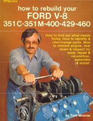
FIG. 5-<strong>Shift</strong><br />
7C316. 7240<br />
SPRING --:<br />
7234 .<br />
Rails and Forks Disassembled<br />
3. Raise the vehicle on a hoist.<br />
4. Disconnect the three shift rods<br />
at the transmission by removing the<br />
hair pin type retainer (Fig. 3).<br />
5. Remove the three bolts retaining<br />
the shift assembly to the transmission<br />
extension housing and remove the shift<br />
assembly.<br />
6. Remove the back up light switch<br />
from the shift assembly.<br />
7. Remove the snap ring from the<br />
end <strong>of</strong> the selector shaft with pointed<br />
snap ring pliers (Fig. 12).<br />
8. Remove the flat washer and<br />
spring.<br />
9. After removing two bolts, pull<br />
the retainer, selector levers and bracket<br />
from the shaft.<br />
10. Drive the short selector lever<br />
pin from the shaft with a large pin<br />
punch.<br />
11. Drive the long trunion pin from<br />
1"'"<br />
l.iW~~;;:!;;ifJ<br />
SCREW ~<br />
377886 - S ~<br />
SHIFT FORK<br />
7231<br />
DETENT PLUG -7C316<br />
SPRING<br />
7234<br />
I<br />
ffj-MAGNETIC DRAIN PLUG -373719-5<br />
BOLT<br />
378206.:<br />
C 1568- A<br />
the shaft and remove the trunion and<br />
shaft.<br />
12. Clean and inspect all parts.<br />
13. Lubricate all mating friction<br />
surfaces with Rotunda Lube CIAZ-<br />
19586-B.<br />
14. Install the shaft in the bracket.<br />
Position the trunion and drive the<br />
long straight pin through the trunion<br />
and into the shaft until an equal length<br />
<strong>of</strong> the pin is exposed on both sides<br />
<strong>of</strong> the shaft.<br />
15. Drive the short pin into the shaft<br />
until the pin is centered in the shaft.<br />
16. Install the selector levers and<br />
neutral index on the shaft as shown in<br />
Fig. 12.<br />
17. Position the retainer and start<br />
the bolts. Before tightening the bolts,<br />
be sure that the retainer is not interfering<br />
with free movement <strong>of</strong> the shaft.<br />
Tighten the bolts.