group 6 Manual Shift Transmissions.pdf - Index of
group 6 Manual Shift Transmissions.pdf - Index of
group 6 Manual Shift Transmissions.pdf - Index of

Create successful ePaper yourself
Turn your PDF publications into a flip-book with our unique Google optimized e-Paper software.
6-1<br />
PART 6-1<br />
PAGE<br />
General Transmission Service 6-1<br />
PART 6-2<br />
Model 2.77 Three-Speed<br />
Transmission 6-10<br />
PART 6-3<br />
Model 3.03 Three-Speed<br />
Transmission 6-16<br />
PART 6-4<br />
PAGE<br />
Ford Design Four-Speed<br />
Transmission 6-25<br />
PART 6-5<br />
Overdrive Transmission 6-35<br />
PART 6-6<br />
Specifications 6-46<br />
Section<br />
Page<br />
1 Diagnosis and Testing 6-1<br />
2 Common Adjustments and Repairs ,6-1<br />
Rear Seal Replacement 6-1<br />
Rear Bushing and Seal Replacement 6-1<br />
Section<br />
Page<br />
Lubrication 6-2<br />
3 Cleaning and Inspection 6-2<br />
Cleaning .""""""""...'."""."""""'.'.'.'." .6-2<br />
Inspection 6-2<br />
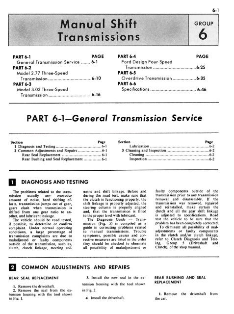
DIAGNOSIS AND TESTING<br />
The problems related to the transmission<br />
usually are: excessive<br />
amount <strong>of</strong> noise, hard shifting efforts,<br />
transmission jumps out <strong>of</strong> gear,<br />
gears clash when transmission is<br />
shifted from one gear ratio to another,<br />
and lubricant leakage.<br />
The vehicle should be road tested,<br />
if possible, to determine or confirm<br />
complaint. Under normal operating<br />
conditions, a large percentage <strong>of</strong><br />
transmission complaints are due to<br />
maladjusted or faulty components<br />
outside <strong>of</strong> the transmission, such as,<br />
clutch, clutch linkage, steering columns<br />
and shift linkage. Before and<br />
during the road test, make sure that<br />
the clutch is functioning properly, the<br />
shift linkage is properly adjusted, the<br />
steering column is properly aligned<br />
and, that the transmission is filled<br />
to the proper level with lubricant.<br />
The Diagnosis Guide -- Transmission<br />
(Fig. 5) is compiled as a<br />
guide in correcting problems related<br />
to manual transmissions. Trouble<br />
symptoms, possible causes and corrective<br />
measures are listed in the order<br />
they should be checked to eliminate<br />
all possibility <strong>of</strong> maladjustment or<br />
faulty components outside <strong>of</strong> the<br />
transmission prior to any transmission<br />
removal and disassembly. If the<br />
transmission was removed, repaired<br />
and rei nstalled, make certain the<br />
clutch and all the gear shift linkage<br />
is adjusted to specifications. Road<br />
test the vehicle to be sure that the<br />
problem has been completely corrected.<br />
To eliminate all possibility <strong>of</strong> maladjustments<br />
or faulty components<br />
in the clutch and/or clutch linkage,<br />
refer to Clutch Diagnosis and Testing,<br />
Group 5 (Driveshaft and<br />
Clutch), <strong>of</strong> the shop manual.<br />
COMMON ADJUSTMENTS AND REPAIRS<br />
REAR SEAL REPLACEMENT<br />
1. Remove the driveshaft.<br />
2. Remove the seal from the extension<br />
housing with the tool shown<br />
in Fig. I.<br />
3. Install the new seal in the extension<br />
housing with the tool shown<br />
in Fig. 2.<br />
4. Install the driveshaft.<br />
REAR BUSHING AND SEAL<br />
REPLACEMENT<br />
I. Remove the driveshaft from<br />
the car.
6-2 GROUP 6-<strong>Manual</strong> <strong>Shift</strong> <strong>Transmissions</strong><br />
2. Insert the tool shown in Fig. 3<br />
into the extension housing until it<br />
grips the front side <strong>of</strong> the bushing.<br />
3. Turn the screw clockwise until<br />
the seal and the bushing are free <strong>of</strong><br />
the housing.<br />
4. Drive a new bushing into the<br />
extension housing with the tool shown<br />
in Fig. 4.<br />
S. Install a new seal in the housing<br />
as shown in Fig. 2.<br />
6. Install the driveshaft.<br />
LUBRICA TION<br />
FIG. 7<br />
Tool-1175-A8<br />
I<br />
TooI-T50T-JOO-A<br />
Removing Extension Housing Seal<br />
..<br />
"',<br />
'"<br />
C1174-F<br />
Lubrication level should be in line<br />
with the bottom <strong>of</strong> filler hole right<br />
side <strong>of</strong> transmission case.<br />
Too/-T60K-7697-A<br />
OR 7000-AF<br />
T 52 L - 7000 GAE<br />
C1173-C<br />
FIG. 3- Removing Extension Housing<br />
Bushing a nd Sea I<br />
C1176.0<br />
FIG. 4- Installing Extension Housing<br />
Bushing<br />
FIG. 2-lnstall<br />
Seal<br />
Extension Housing<br />
CLEANING AND INSPECTION<br />
CLEANING<br />
I. Wash all parts, except the ball<br />
bearings and seals in a suitable<br />
cleaning solvent. Brush or scrape all<br />
foreign matter from the parts. Be carefull<br />
not to damage any parts with<br />
the scraper. Dry all parts with compressed<br />
air. Do not clean, wash or<br />
soak transmission seals in cleaning<br />
solfent.<br />
2. Rotate the ball bearings in a<br />
cleaning solvent until all lubricant is<br />
removed. Hold the bearing assembly<br />
to prevent it from rotating and dry<br />
it with compressed air.<br />
3. Lubricate the bearings with approved<br />
transmission lubricant and<br />
wrap them in a clean, lint-free cloth<br />
or paper until ready for use.<br />
INSPECTION<br />
I. Inspect the transmission case<br />
for being cracked, worn or damaged<br />
bearing bores, damaged threads or<br />
any other damage which could affect<br />
the operation <strong>of</strong> the transmission.<br />
2. Inspect the front face <strong>of</strong> the<br />
case for small nicks or burrs that<br />
could cause misalignment <strong>of</strong> the<br />
transmission with the flywheel housing.<br />
Remove all small nicks or burrs with<br />
a fine stone.<br />
3. Replace a cover that is bent or<br />
distorted. Make sure that the vent<br />
hole in the cover is open.<br />
4. Check the condition <strong>of</strong> the shift<br />
levers, forks, shift rails and the lever<br />
and shafts.<br />
5. Examine the ball bearing races<br />
for being cracked, worn or rough. Inspect<br />
the balls for looseness, wear,<br />
end play or other damage. Check the<br />
bearings for looseness in the bores.<br />
If any <strong>of</strong> these conditions exist, replace<br />
the bearings.<br />
6. Replace roller bearings that are<br />
broken, worn or rough.<br />
7. Replace the countershaft (cluster)<br />
gear if the teeth are chipped,<br />
broken or worn. Replace the countershaft<br />
if it is bent, scored or worn.<br />
8. Replace the reverse idler gear<br />
or slidi ng gear if the teeth are<br />
chipped, worn or broken. Replace the<br />
idler gear shaft if bent, worn or<br />
scored.<br />
9. Replace the input shaft and<br />
gear if the splines are damaged or if
PART 6-1-General Transmission Service<br />
6-3<br />
the teeth are chipped, worn or broken.<br />
If the roller bearing surface in the<br />
bore <strong>of</strong> the gear is worn or rough,<br />
or if the cone surface is damaged,<br />
replace the gear and the gear rollers.<br />
10. Replace all other gears that<br />
are chipped, broken or worn.<br />
II. Check the synchronizer sleeves<br />
for free movement on their hubs.<br />
Make sure that the alignment marks<br />
(etched marks) are properly indexed.<br />
12. Inspect the synchronizer blocking<br />
rings for widened index slots,<br />
rounded clutch teeth and smooth internal<br />
surfaces (must have machined<br />
grooves). With the blocker ring on<br />
the cone, the distance between the<br />
face <strong>of</strong> the blocker ring and the<br />
clutch teeth on the gear must not<br />
be less than 0.0 10 inches.<br />
13. Replace the speedometer drive<br />
gear if the t~th are stripped or damaged.<br />
Make certain to install the<br />
correct size replacement gear.<br />
14. Replace the output shaft if<br />
there is any evidence <strong>of</strong> wear or if<br />
any <strong>of</strong> the splines are damaged.<br />
15. Inspect the bushing and the<br />
seal in the extension housing. Replace<br />
them if they are worn or damaged.<br />
The bushing and/or seal should<br />
be replaced after the extension housing<br />
has been installed on the transmission.<br />
16. Replace the seal on the input<br />
shaft bearing retainer.<br />
17. Replace the seals on the cam<br />
and shafts.
6-4 GROUP 6-<strong>Manual</strong> <strong>Shift</strong> <strong>Transmissions</strong><br />
TROUBLE SYMPTOMS POSSIBLE CAUSES CORRECTION<br />
RATTLE OR BUZZ IN<br />
FLOOR SHIFT LEVER<br />
Some floor shift transmissions are<br />
subject to shift lever buzz or rattle.<br />
No transmission overhaul should be<br />
attempted to correct this problem as<br />
it. is <strong>of</strong>ten mistaken for a grating<br />
noise in the transmission.<br />
1. Loose nuts at transmission levers<br />
and shift rods. If the nuts are<br />
loose, check for bell-mouthing <strong>of</strong><br />
slots.<br />
2. Bent transmission shift rods or<br />
linkage interference.<br />
3. Lack <strong>of</strong> lubrication <strong>of</strong> shift<br />
linkage, trunnions and external shift<br />
mechanism (floor shift).<br />
4. Improperly located console and<br />
excessive boot compression (floor<br />
shift).<br />
5. Grommets damaged allowing<br />
hold down bolts and/or hold down<br />
washers to ground out against lever<br />
(floor shift).<br />
1. Adjust levers and shift rods to<br />
proper crossover, torque nuts to<br />
specification. Replace bell-mouthed<br />
rods or levers.<br />
2. Replace bent rods or levers.<br />
3. Clean and lubricate with<br />
urn base grease (no Polethylene). .ithi-<br />
4. Install correctly.<br />
5. Replace defective parts. Install<br />
correctly.<br />
GEAR CLASH<br />
CLUTCH LINKAGE<br />
1. Lack <strong>of</strong> clutch pedal reserve,<br />
free play and total travel.<br />
2. Bottoming <strong>of</strong> clutch release<br />
arm in window <strong>of</strong> clutch housing.<br />
3. Bent or cracked equalizer bar.<br />
1. Adjust to specification.<br />
2. Grind opening in clutch housing<br />
or release arm to provide clearance.<br />
3. Replace defective parts.<br />
SHIFT LINKAGE<br />
1. Improper crossover.<br />
2. Loose nuts at transmission levers<br />
and shift rods. If the nuts are<br />
loose, check for bell-mouthing <strong>of</strong><br />
slots.<br />
3. Bent transmission shift rods or<br />
linkage interference.<br />
4. Lack <strong>of</strong> lubrication <strong>of</strong> shift<br />
linkage, trunnions and external shift<br />
mechanism (floor shift).<br />
1-2. Adjust levers and shift rods<br />
to proper crossover, torque nuts to<br />
specification. Replace bell-mouthed<br />
rods or levers.<br />
3. Replace bent rods<br />
4. Clean and lubricate with Lith.<br />
ium base grease (no Polyethylene).<br />
CLUTCH<br />
1. Excessive engine idle speed.<br />
2. Inadequate clutch pcdal reserve<br />
resulting in excessive spin time.<br />
3. Incorrect pedal free travel.<br />
4. Disc binding on transmission<br />
input shaft.<br />
5. Excessive disc runout.<br />
6. Flywheel housing misalignment.<br />
7. Oil or grease on clutch facings<br />
from:<br />
A. Release bearing<br />
B. Engine<br />
C. Release lever<br />
D. Pilot bearing<br />
E. Transmission<br />
I. Adjust engine idle rpm.<br />
2. Adjust clutch linkage to specification.<br />
Check for damaged input<br />
shaft pilot bearing or excessive clutch<br />
disc runout-replace defective parts.<br />
3. Adjust to specification.<br />
4. Check for burrs on splines, replace<br />
if necessary.<br />
5-7-8. Replace clu tch disc.<br />
6. Align to specification.<br />
FIG. 5- Diagnosis Guide. - <strong>Transmissions</strong><br />
Continued on next page
PART 6-1-General Transmission Service<br />
6-5<br />
TROUBLE SYMPTOMS POSSIBLE CAUSES CORRECTION<br />
GEAR CLASH (Continued)<br />
8. Damaged<br />
clutch lining.<br />
or<br />
contaminated<br />
TRANSMISSION<br />
I. Forward Gear Clash<br />
A. Weak or broken insert<br />
springs in the synchronizer assembly.<br />
B. Worn blocking rings and/or<br />
cone surfaces.<br />
I. A-B-C-D-F-G Replace worn or<br />
defective parts.<br />
C. Broken blocking rings.<br />
D. Excessive output shaft end<br />
play Ė. <strong>Shift</strong>er fork loose on shift E. Torque shifter<br />
screws to specification.<br />
rails.<br />
F. Binding input shaft pilot<br />
bearing (non-synchronized low gear<br />
transmission only).<br />
G. Worn shifter forks or sleeves.<br />
fork<br />
set<br />
2. Reverse Gear Clash (Allow approximately<br />
three-four seconds after<br />
the clutch pedal has been depressed<br />
before shifting into reverse gear).<br />
A. I f gear clash continues after<br />
allowing proper time for the clutch<br />
plate to stop, check the clutch adjustments<br />
to make sure that they are<br />
within specifications.<br />
B. Excessive engine idle speed.<br />
C. Binding input shaft pilot<br />
bearing.<br />
D. Wom or damaged clutch<br />
disc<br />
2. A. Adjust clutch to specification-See<br />
possible causes under<br />
Clutch for gear clash trouble symtoms.<br />
B. Adjust engine idler rpm.<br />
CoD. Replace defective parts.<br />
HARD SHIFTING<br />
SHIFT LINKAGE<br />
1. Improper crossover.<br />
2. Loose nu ts at transmission levers<br />
and shift rods. If the nuts are<br />
loose, check for bell-mouthing <strong>of</strong><br />
slots.<br />
3. Bent transmission shift rods or<br />
linkage interference.<br />
4. Lack <strong>of</strong> lubrication <strong>of</strong> shift<br />
linkage, trunnions and external shift<br />
mechanism (floor shift).<br />
5. Improperly located console and<br />
excessive boot compression (floor<br />
shift).<br />
1-2. Adjust levers and rods to<br />
proper crossover, torque nuts to specification.<br />
Replace bell-mouthed rods<br />
or levers.<br />
3. Replace bent rods or levers.<br />
4. Clean and lubricate with Lithium<br />
base grease (no Polyethylene).<br />
5. Install correctly.<br />
STEERING COLUMNS<br />
1. Improper column alignment,<br />
looseness, binding and worn surfaces.<br />
Make certain the toe plate at the<br />
base <strong>of</strong> the column is fastened securely<br />
to the firewall.<br />
2. Worn shift key or broken weld<br />
securing shift key to top or bottom<br />
<strong>of</strong> shift tube.<br />
3. Loose shift lever pin in die cast<br />
selector lever hub.<br />
4. Keyway in die cast selector lever<br />
hub pounded out.<br />
1. Align column properly, replace<br />
defective column parts and fasten<br />
toe plate to firewall securely.<br />
2-3-4. Replace defective parts.<br />
FIG. 5 (Continued)-Diagnosis Guide- <strong>Transmissions</strong><br />
Continued on next page
6-6 GROUP 6-<strong>Manual</strong> <strong>Shift</strong> lransmissions<br />
TROUBLE SYMPTOMS POSSIBLE CAUSES CORRECTION<br />
HARD SHIFTING<br />
(Continued)<br />
5. Alignment <strong>of</strong> column to steering<br />
gear pilot bushing.<br />
6. Loose screws securing die casting<br />
to bottom <strong>of</strong> tube. Excessive radial<br />
movement in the column linkage.<br />
(If the vehicle has high mileage<br />
or is subjected to hard use, even<br />
though the (rossover has been properly<br />
set, the column may have deteriorated<br />
to a point where proper<br />
crossover engagement will not occur<br />
due to excessive radial movement in<br />
the column linkage (lost motion).<br />
7. Lack <strong>of</strong> lubrication at column<br />
lower plate.<br />
5. Align properly.<br />
6. Replace defective parts. Tight.<br />
en screws securely.<br />
7. Clean and lubricate with Lithium<br />
base grease (no Polyethylene).<br />
CLUTCH LINKAGE<br />
I. Loss <strong>of</strong> clutch pedal reserve,<br />
free play and total travel.<br />
1. Adjust to specification<br />
TRANSMISSION<br />
1. Excessive shift effort.<br />
A. <strong>Shift</strong> levers, shafts or forks<br />
worn or bent.<br />
B. Synchronizer worn or broken<br />
C-D. Install correctly,<br />
C. <strong>Shift</strong> rail components not<br />
functioning properly.<br />
D. Worn shifter forks or<br />
sleeves.<br />
A-B. Replace worn or defective<br />
parts.<br />
defective parts, if necessary.<br />
replace<br />
2. Sticking in Gear.<br />
A. Low lubricant level.<br />
B. Corroded transmission levers<br />
(shaft).<br />
C. Defective (tight) input shaft<br />
pilot bearing.<br />
D. Stuck detent plug.<br />
E. Burred or battered teeth on<br />
synchronizer sleeve and/or input shaft.<br />
F. <strong>Shift</strong>er fork loose on shift<br />
rails<br />
2. A. Fill to bottom <strong>of</strong> filler plug<br />
hole.<br />
B-D. Free-up and clean parts,<br />
replace if necessary.<br />
C-E. Replace defective parts.<br />
F. Torque shifter fork set<br />
screw to specification.<br />
GEAR JUMPOUT<br />
SHIFT LINKAGE<br />
FIG. 5 (Continue d)-Diagnosis Guide<br />
1. Improper crossover.<br />
2. Loose nuts at transmission levers<br />
and shift rods. If the nuts are<br />
loose, check for bell-mouthing <strong>of</strong><br />
slots.<br />
3. Bent transmission shift rods or<br />
linkage interference.<br />
4. Lack <strong>of</strong> lubrication <strong>of</strong> shift<br />
linkage, trunnions and external shift<br />
mechanism (floor shift).<br />
5. Improperly located console and<br />
excessive boot compression (floor<br />
shift).<br />
Transmissi ons<br />
1-2. Adjust levers and rods to<br />
proper crossover. Torque nuts to<br />
specification. Replace bell-mouthed<br />
rods or levers.<br />
3. Replace bent rods or levers.<br />
4. Clean and lubricate with Lith.<br />
ium base grease (no Polyethylene).<br />
5. Install correctly<br />
Continued on next page
PART 6-1-General Transmission Service 6-7<br />
TROUBLE SYMPTOMS<br />
POSSIBLE CAUSES<br />
CORRECTION<br />
GEAR JUMPOUT<br />
( Continued)<br />
STEERING COLUMNS<br />
I. Improper column alignment<br />
looseness, binding and worn surfaces.<br />
Make certain the toe plate at the<br />
base <strong>of</strong> the column is fastened securely<br />
to the firewall.<br />
2. Alignment <strong>of</strong> column to steering<br />
gear pilot bushing.<br />
3. Worn shift key or broken weld<br />
securing shift key to top or bottom<br />
<strong>of</strong> shift tube.<br />
4. Keyway in die cast selector lever<br />
hub pounded out.<br />
5. Loose screws securing die casting<br />
to bottom <strong>of</strong> tube. Excessive<br />
radial movement in the column linkage.<br />
(If the vehicle has high mileage<br />
or is subjected to hard use, even<br />
though the crossover has been properly<br />
set, the column may have deteriorated<br />
to a point where proper<br />
crossover engagement will not occur<br />
due to excessive radial movement in<br />
the column linkage (lost motion).<br />
1. Align column properly, replace<br />
defective column parts and fasten<br />
toe plate to firewall securely.<br />
2. Align properly.<br />
3-4. Replace defective parts.<br />
5. Replace defective parts. Tighten<br />
screwsecurely.<br />
TRANSMISSION<br />
I. Transmission<br />
loose.<br />
2. Bent or worn shift fork, lever<br />
and/or shaft.<br />
3. Worn input shaft pilot bearing.<br />
4. End play in input shaft (bearing<br />
retainer loose or broken, loose<br />
or worn bearings on input and ;Jutput<br />
shafts).<br />
5. Detent springs broken.<br />
6. Detent notches worn.<br />
7. Worn clutch teeth on the respective<br />
gear and/or worn clutch<br />
teeth on synchronizer sleeve.<br />
8. <strong>Shift</strong>er forks loose on shift<br />
rails.<br />
misaligned or I. Align to specification. Torque<br />
transmission-to-flywheel housing bolts<br />
and flywheel housing-to-engine bolts<br />
to specifications.<br />
2-3-5-6-7. Replace worn or defective<br />
parts.<br />
4. Torque retainer bolts to specification.<br />
Replace worn or defective<br />
parts.<br />
8, Torque shifter fork set screw<br />
to specification.<br />
LOCKED IN GEAR<br />
When a complaint <strong>of</strong> momentary<br />
locknut is encountered in<br />
transmissions with non-synchronized<br />
low - gear, determine whether or not<br />
a normal "blockout" condition exists.<br />
If a "blockout" condition does<br />
exist, the customer should be informed<br />
that the transmission gears can-<br />
SHIFT LINKAGE<br />
1. Improper crossover.<br />
2. Loose nu ts at transmission levers<br />
and shift rods. If the nuts are<br />
loose, check for bell-mouthing <strong>of</strong><br />
slots.<br />
3. Bent transmission shift rods or<br />
linkage interference.<br />
1-2. Adjust levers and rods to<br />
proper crossover. Torque nuts to<br />
specification. Replace bell-mouthed<br />
rods and levers.<br />
3. Replace bent rods or levers.<br />
---<br />
FIG. 5 (Continued)-Diagnosis Guide-<strong>Transmissions</strong>
6-8 GROUP 6-<strong>Manual</strong> <strong>Shift</strong> <strong>Transmissions</strong><br />
TROUBLE SYMPTOMS POSSIBLE CAUSES CORRECTION<br />
LOCKED IN GEAR<br />
(Continued)<br />
not be pulled into mesh because <strong>of</strong><br />
gear tooth to tooth abutment which<br />
can be eliminated by releasing and<br />
depressing the clutch pedal again<br />
(thus spinning the clutch disc). This<br />
I will re-index the drive and driven<br />
,gear teeth and allow the gears to<br />
mesh.<br />
STEERING COLUMN<br />
1. Tricking <strong>of</strong> shift linkage. Make<br />
certain that when slowly shifting out<br />
<strong>of</strong> low gear, the low gear shift lever<br />
at the transmission is completely out<br />
<strong>of</strong> low gear detent prior to the column<br />
shift lever dropping through neutral<br />
crossover. If the transmission shift lever<br />
is not completely out <strong>of</strong> low gear<br />
detent, the shift interlock in the transmission<br />
will prevent engagement <strong>of</strong><br />
second gear and a lockup condition<br />
occurs.<br />
2. Improper column alignment,<br />
looseness, binding and worn surfaces.<br />
Make certain the toe plate at the<br />
base <strong>of</strong> the column is fastened securely<br />
to the firewall.<br />
3. Alignment <strong>of</strong> column to steering<br />
gear pilot bushing.<br />
4. Worn shift key or broken weld<br />
securing shift key to top or bottom<br />
<strong>of</strong> shift tube.<br />
5. Loose shift lever pin in die<br />
cast selector lever hub.<br />
6. Keyway in die cast selector<br />
lever hub pounded out.<br />
7. Loose screws securing die casting<br />
to bottom <strong>of</strong> tube. Excessive radial<br />
movement in the co.lumn linkage.<br />
(If the vehicle has high mileage or<br />
is subjected to hard use even though<br />
the crossover has been properly set,<br />
the column may have deteriorated to<br />
a point where proper crossover engagement<br />
will not occur due to excessive radial<br />
movement in the column linkage<br />
(lost motion). Lack <strong>of</strong> lubrication at<br />
column lower plate.<br />
CORRECTION<br />
1-2. Adjust column properly, replace<br />
defective parts and fasten toe<br />
plate to firewall securely.<br />
3. Align properly.<br />
4-5-6. Replace defective parts.<br />
7. Replace defective parts. Tighten<br />
screws securely. Clean and lubricate<br />
with Lithium base grease (no<br />
Polyethylene).<br />
TRANSMISSION<br />
1. <strong>Shift</strong> rail components not functioning<br />
properly.<br />
2. Gear seizure.<br />
3. Synchronizer inserts out <strong>of</strong> position.<br />
1-3. I nstall correctly, replace de.<br />
fective parts.<br />
2. Replace defective parts.<br />
NOISY IN FORWARD<br />
SPEEDS<br />
Low lubricant level<br />
2. Transmission<br />
loose.<br />
misaligned<br />
or<br />
3. Input shaft bearings worn or<br />
damaged.<br />
4. Output shaft bearing worn or<br />
damaged.<br />
I. Fill to bottom <strong>of</strong> filler plug<br />
hole.<br />
2. Align to specification. Torque<br />
transmission-to-flywheel housing bolts<br />
end flywheel housing-to-engine bolts<br />
to specifications.<br />
3-4-5-6-7. Replace worn or defective<br />
parts.<br />
FIG. 5 (Cont;nued)-Diagnosis Guide- Tra nsmissions Continued on next page
PART 6-1-General Transmission Service 6-9<br />
TROUBLE SYMPTOMS POSSIBLE CAUSES CORRECTION<br />
NOISY IN FORWARD<br />
SPEEDS (Continued)<br />
5. Mainshaft gears worn or damaged.<br />
(In any case <strong>of</strong> scored or<br />
broken gears. the mating gears should<br />
be checked).<br />
6. Countershaft gear or bearings<br />
worn or damaged.<br />
7. Failure <strong>of</strong> the operator to fully<br />
engage the gears on every shift before<br />
engaging the clutch and applyingenginepo~er.<br />
Gear roll-over noise, inherent in<br />
manual transmissions, is caused by<br />
the constant mesh gears turning at<br />
engine idle speed, while the clutch is<br />
engaged and the transmission in neutral:<br />
and throwout bearing rub are<br />
sometimes mistaken for mainshaft<br />
bearing noise.<br />
Gear roll-over noise will disappear<br />
when the clutch is disengaged or<br />
when the transmission is engaged in<br />
gear. Throwout bearing rub will disappear<br />
when the clutch is engaged.<br />
In the event that a bearing is defective,<br />
the noise is more pronounced<br />
while engaged in gear under load or<br />
coast than in neutral. When complaints<br />
<strong>of</strong> this nature are encountered,<br />
it will be necessary to road test the<br />
vehicle to determine if bearing noise<br />
exists. Under no circumstances<br />
should any transmission rework be<br />
attempted to eliminate gear rollo,er<br />
noise, or throwout bearing rub.<br />
NOISY IN REVERSE<br />
I. Reverse idler gear or shaft.<br />
worn or damaged.<br />
2. Reverse sliding gear worn or<br />
broken.<br />
1-2. Rt:plact: worn or defectivt:<br />
parts.<br />
LUBRICANT<br />
LEAKS<br />
I. Excessive lubricant<br />
2. Vent plugged.<br />
3. Input shaft bearing retainer<br />
loose or cracked, seal or gasket damaged.<br />
4, Worn or damaged extension<br />
housing seal.<br />
5. Worn shifter shaft seals.<br />
6. Extensi9n housing bolts not<br />
sealed.<br />
7. Expansion plug at front <strong>of</strong><br />
case not seated properly.<br />
S. Access cover loose or gasket<br />
damaged.<br />
I. Drain to bottom <strong>of</strong> filler plug<br />
hole.<br />
2. Free up.<br />
3. Add sealer and torque retainer<br />
bolts to specifications. Replace defective<br />
parts.<br />
4-5. Replace defective parts.<br />
6-7-8. Add sealer to bolts,<br />
and torque to specifications. Replace<br />
defective parts.<br />
FIG. 5 (Cont;nuedJ-Diaanosis Guide- <strong>Transmissions</strong>
1 Description and Operation<br />
noitarepO<br />
noitpircseD<br />
Disassembly<br />
J Removal and Instalation<br />
4 Major noitalatsnI<br />
Repair Operations<br />
Input Output Synchronizer<br />
Shaft Shaft Bearing Bearing<br />
6-10<br />
Section<br />
2 In-Vehicle Adjustments and Repairs<br />
Gear <strong>Shift</strong> Linkage Adjustment ...,<br />
Removal<br />
Page<br />
6-10<br />
6-10<br />
6-10<br />
6-11<br />
6-11<br />
6-11<br />
, 6-11<br />
, 6-11<br />
6-12<br />
6-12<br />
Section<br />
Parts Repair or Replacement<br />
Gear Cam and <strong>Shift</strong> Shaft Lever and Oil Seals<br />
Countershaft Gear Bearings.<br />
Front Bearing Retainer Seal<br />
Assembly<br />
Page<br />
6-13<br />
6-13<br />
6-14<br />
6-14<br />
6-14<br />
...6-14<br />
6-14<br />
6-14<br />
6-14<br />
DESCRIPTION AND OPERATION<br />
DESCRIPTION<br />
The 2.77 C.D. three-speed transmission<br />
is used in all Falcon models<br />
except station wagons with a 170 or<br />
200 C.I.D. engine. The designation<br />
2.77 C. D. is the actual distance between<br />
the centerline <strong>of</strong> the countershaft<br />
and the centerline <strong>of</strong> the input shaft.<br />
An identification plate (Fig. 1) is<br />
attached to the upper right extension<br />
housing attaching bolt.<br />
A synchronizer is provided for<br />
shifting to second and third speeds.<br />
<strong>Shift</strong>s to first and reverse speeds are<br />
accomplished with a sliding gear.<br />
Ball bearings support the input<br />
shaft and gear and the center <strong>of</strong> the<br />
output shaft. Needle bearings in the<br />
input shaft bore support the front<br />
<strong>of</strong> the output shaft. The countershaft<br />
gear (cluster gear) also runs on 2<br />
rows <strong>of</strong> needle bearings. A bronze<br />
bushing is used in the reverse idler<br />
gear.<br />
A bushing located at the rear <strong>of</strong><br />
the extension housing supports the<br />
rear <strong>of</strong> the output shaft. The synchronizer<br />
and the blocking rings are<br />
the conventional tapered ring and<br />
straight clutch gear type.<br />
OPERATION<br />
When first gear is selected, the<br />
shift lever moves the first and reverse<br />
sliding gear into mesh with the low<br />
gear on the countershaft (cluster)<br />
gear. Power flow is now from the input<br />
gear, through the countershaft<br />
gear to the first and reverse sliding<br />
gear and out through the output<br />
shaft.<br />
When second gear is selected, the<br />
FIG. 1.<br />
shift lever moves the second and<br />
third speed synchronizer sleeve rearward<br />
to force the blocking ring conical<br />
surface against the matching cone<br />
on the constant mesh intermediate<br />
gear located on the output shaft.<br />
When the vehicle is moving, as when<br />
shifting from low to a higher gear<br />
ratio, the internal teeth <strong>of</strong> the synchronizer<br />
sleeve and those on the<br />
blocking ring will not index until the<br />
intermediate gear is brought up or<br />
down to the speed <strong>of</strong> the synchronizer<br />
sleeve which is rotating at output<br />
shaft speed.<br />
The synchronizer sleeve with further<br />
movement will slide over the<br />
blocking ring and engage the clutch<br />
teeth on the constant mesh intermediate<br />
gear. Since the intermediate<br />
gear is now locked to the output<br />
shaft by means <strong>of</strong> the synchronizer<br />
sleeve, power flow is from the input<br />
shaft through the countershaft gear<br />
CHANGE WITHIN TRANSMISSION AFFECTING<br />
INTERCHANGEABILITY OF COMPONENT PARTS<br />
C1345.B<br />
to the constant mesh intermediate<br />
gear to the output shaft.<br />
Engagement <strong>of</strong> third speed is the<br />
same as second except for ratio. In<br />
third gear, the clutch teeth on the<br />
input shaft are locked directly to the<br />
output shaft by the second and third<br />
speed synchronizer to provide a ratio<br />
<strong>of</strong> 1:1.<br />
Reverse gear is accomplished by<br />
moving the first and reverse sliding<br />
gear rearward to engage the reverse<br />
idler gear. The drive is then from<br />
the input gear, through the countershaft<br />
gear, to and through the reverse<br />
idler gear to the first and reverse<br />
sliding gear which is splined to<br />
the output shaft. The gears in this<br />
position will rotate the output shaft<br />
in a reverse direction.<br />
An interlock pin prevents selection<br />
<strong>of</strong> more than one gear at a time. Detent<br />
balls are provided to hold the<br />
selected gear in the desired position.
PART 6-2-Model 2.77 Three-Speed Transmission 6-1<br />
IN-VEHICLE ADJUSTMENTS AND REPAIRS<br />
GEAR SHIFT LINKAGE<br />
ADJUSTMENT<br />
I. Place the gearshift lever in the<br />
neutral position.<br />
2. Loosen the two gearshift rod<br />
adjustment nuts.<br />
3. Insert a dealer fabricated special<br />
tool in the slot provided in the<br />
lower steering column (See Fig. 2).<br />
It may be necessary to align the<br />
levers to insert the tool.<br />
4. Tighten the two gearshift rod<br />
adjustment nuts.<br />
S. Remove the tool from the slot<br />
in the steering column.<br />
6. Start the engine and shift the<br />
selector lever to each position to make<br />
sure it operates freely.<br />
FIG. 2.<br />
Falcon Gearshift linkage Adjustment<br />
REMOVAL AND INSTAllATION<br />
REMOVAL<br />
I. Raise the car on a hoist.<br />
2. Remove the driveshaft. Insert<br />
the extension housing seal installation<br />
tool, Fig. 2, Part 6-1, into the<br />
opening <strong>of</strong> the extension housing to<br />
prevent the lubricant from leaking<br />
out.<br />
3. Disconnect the speedometer cable<br />
from the extension housing, and<br />
disconnect the gear shift rods from the<br />
transmission shift levers.<br />
On a Mustang, remove the three<br />
bolts that attach the shift selector<br />
assembly to the extension housing<br />
and allow the assembly to hang by<br />
the shift lever.<br />
4. Remove the two nuts retaining<br />
the transmission rear support to the<br />
crossmember.<br />
5. Place a transmission jack under<br />
the flywheel housing and raise the<br />
rear <strong>of</strong> the engine slightly.<br />
6. Remove the two cotter pins.<br />
nuts, and bolts that attach the crossmember<br />
to the frame supports.<br />
7. Disconnect the brake cable<br />
from the equalizer lever. Separate<br />
the lever from the crossmem ber.<br />
8. Remove the crossmember from<br />
the frame supports and allow it to<br />
hang by the brake cable.<br />
9. Move the jack under the transmission.<br />
Remove the four transmission<br />
to flywheel housing mounting bolts.<br />
10. Move the transmission back<br />
just far enough to clear the input<br />
shaft and remove it from under the<br />
air.<br />
INSTAllATION<br />
I. Install two guide pins in the<br />
flywheel housing lower mounting<br />
holes. Start the input shaft through<br />
the release bearing. Align the output<br />
shaft splines with the splines in the
1._1 <br />
GROUP 6-<strong>Manual</strong> <strong>Shift</strong> <strong>Transmissions</strong><br />
clutch disc. Move the transmission<br />
forward on to the guide pins. If the<br />
transmission front bearing retainer<br />
hangs-up on the release bearing hub,<br />
move the clutch release lever to free it.<br />
2. Move the transmission forward<br />
until the input shaft is through the<br />
clutch hub and enters the pilot bearing.<br />
3. Install the !WO upper transmission<br />
to flywheel housing attaching<br />
bolts and lockwashers.<br />
.1- Remove the two I!uide Dins and<br />
install the two lower attaching bolts.<br />
Torque all attaching bolts to specifications.<br />
5. Position the crossmember to<br />
the frame supports. Install the equalizer<br />
lever and brake cable.<br />
6. Secure the transmission rear<br />
support to the crossmember. Secure<br />
the crossmember to the frame supports<br />
and remove the transmission jack.<br />
7. Connect the gear shift rods and<br />
the speedometer cable.<br />
On a Mustang, position the shift<br />
selector assembly to the extension<br />
housing and install the attaching<br />
bolts.<br />
8. Remove the tool (Fig. 2, Part<br />
6-1) from the rear <strong>of</strong> the extension<br />
housing. Install the driveshaft, and<br />
torque rear V-bolt nuts to specification.<br />
9. Fill the transmission with approved<br />
lubricant. Check the shifting<br />
action <strong>of</strong> the transmission.<br />
10. Adjust the clutch pedal total<br />
travel, free travel and shift linkage<br />
as required.<br />
MAJOR REPAIR OPERATIONS<br />
DISASSEMBL Y<br />
2. Remove the transmission cover<br />
and gasket.<br />
I. Mount the transmission in a 3. Remove the extension housing<br />
holding fixture and drain the lubri- attaching bolts and remove the ex-<br />
~_.<br />
tension housing and gasket. To pre-<br />
vent the output shaft from following<br />
the housing (with the resultant loss<br />
<strong>of</strong> needle bearings), tap the end <strong>of</strong><br />
the output shaft with a s<strong>of</strong>t-faced<br />
hammer while withdrawing the exten-<br />
SNAP<br />
RINC<br />
"".." T :..:~" n;.~..o~hlo.
~<br />
PART 6-2-Model 2.77 Three-Speed Transmission<br />
6-13<br />
BOLT-<br />
379818- S<br />
~<br />
A<br />
;ROMME<br />
"7oqIQ.<br />
~<br />
SHIF<br />
.EVER ASSE<br />
FIG. 4-Removing or Installing<br />
Countersh aft<br />
FIG. 5-Removing<br />
"tf<br />
Input Shaft<br />
sion housing. See disassembly (Fig. 3).<br />
4. Remove the speedometer drive<br />
gear snap ring. the gear, and drive<br />
ball from the output shaft.<br />
5. Remove the retainer for the<br />
reverse idler shaft and countershaft<br />
(Fig. 3).<br />
6. Hold the countershaft gear with<br />
a hook and using the tool (dummy<br />
shaft) shown in Fig. 4, drive the<br />
countershaft rearward out <strong>of</strong> the<br />
countershaft gear and the transmission<br />
case. Then, carefully lower the<br />
counters haft gear and dummy shaft<br />
to the bottom <strong>of</strong> the case.<br />
7. After removing the input shaft<br />
bearing retainer and gasket, remove<br />
the input shaft assembly and front<br />
synchronizer blocking ring from the<br />
transmission case (Fig. 5).<br />
@J<br />
ta<br />
"'/, a/ ./PLUNGER-<br />
8. Remove the synchronizer retaining<br />
snap ring from the output<br />
shaft. Then, while holding the synchronizer<br />
assembly together, pull the<br />
output shaft out <strong>of</strong> the transmission<br />
case. The intermediate gear and the<br />
low and reverse gear will slide <strong>of</strong>f the<br />
output shaft as it is withdrawn from<br />
the case. Lift the synchronizer assembly,<br />
intermediate, low and reverse<br />
sliding gears out <strong>of</strong> the case and remove<br />
the two shift forks. For reference<br />
in assembly, notice which synchronizer<br />
hub end faces forward.<br />
9. Using a s<strong>of</strong>t drift, drive the reverse<br />
idler shaft out <strong>of</strong> the transmission<br />
case. Lift the reverse idler gear<br />
and the countershaft gear out <strong>of</strong> the<br />
case.<br />
10. Remove the shift levers.<br />
PARTS REPAIR OR<br />
REPLACEMENT<br />
GEAR SHIFT LEVER<br />
SPRING -<br />
, 7208<br />
- 7B125<br />
1 @ ~ TRUNNION - SNAP RING -<br />
, ',.., 7210 97527-S<br />
~ ~. STRAIGHT PIN (LONG) - FLAT WASHER-<br />
W SUPPORT - 379300-S 371681-S<br />
;PRINI<br />
7416 SPACER - STRAIGHT SHAFT (SHORT)<br />
7C30,<br />
7C383 7AI11 -<br />
SPACER - SELECTOR SHAFT -<br />
7C383 J<br />
\<br />
; 7241 RETAINER -<br />
J 7348<br />
- i~ -.
6-14 GROUP 6-<strong>Manual</strong> <strong>Shift</strong> <strong>Transmissions</strong><br />
9. Drive the short pin into the<br />
shaft until the pin is centered in the<br />
shaft.<br />
10. Install the levers and spacer<br />
on the shaft as shown in Fig. 6.<br />
II. Position the retainer and start<br />
the bolts. Before tightening the bolts<br />
be sure that the retainer is not interfering<br />
with free movement <strong>of</strong> the<br />
shaft. Tighten the bolts.<br />
12. Install the spring, flat washer<br />
and snap ring.<br />
13. Install the lever studs if they<br />
were removed.<br />
CAM AND SHAFTS<br />
AND OIL SEALS<br />
I. From the underside <strong>of</strong> the case,<br />
use a punch to drive out the tapered<br />
pins that hold the cam and shaft assemblies<br />
in the case (Fig. 7). Use<br />
hard, firm blows. Using a plastic<br />
hammer, drive the intermediate and<br />
high cam and shaft toward the inside<br />
<strong>of</strong> the case and separate the detent<br />
balls and spring from the plunger.<br />
Push out the cam and shaft assemblies,<br />
and remove the plunger.<br />
2. If required, the cam and shaft<br />
oil seals in the case may be removed<br />
with the tools shown in Fig. 8 .<br />
3. Install new seals in the case.<br />
4. Install the reverse and low shift<br />
cam and shaft through the case opening.<br />
Assemble the spacer and spring<br />
in the plunger. Apply grease to each<br />
ball and position them in each end <strong>of</strong><br />
the plunger. Hold the plunger assembly<br />
in position and install the intermediate<br />
and high cam and shaft in<br />
the case opening, allowing the balls<br />
to register in the cam detents.<br />
5. Align the cam and shaft grooves<br />
with the openings in the shaft bosses<br />
in the case, and install the retaining<br />
pins. Check the cam action. Bent<br />
pins may restrict movement.<br />
INPUT SHAFT BEARING<br />
1. Remove the snap ring securing<br />
the input shaft bearing, and press the<br />
input shaft out <strong>of</strong> the bearing and oil<br />
slinger.<br />
2. Press the input shaft bearing<br />
and oil slinger onto the input shaft<br />
with the tool shown in Fig. 9, and<br />
install the snap ring on the shaft.<br />
OUTPUT SHAFT BEARING<br />
I. Remove the snap ring securing<br />
the output shaft bearing. Remove the<br />
bearing as shown in Fig. 10.<br />
2. Press the output shaft bearing<br />
onto the shaft as shown in Fig. 10,<br />
and install the snap ring on the shaft.<br />
SYNCHRONIZER<br />
1. Remove the synchronizer sleeve,<br />
blocking rings, inserts, and retainers<br />
from the synchronizer hub.<br />
2. Hold the three inserts in place<br />
in the synchronizer hub (Fig. 3).<br />
3. Align the etch mark on the hub<br />
with the etch mark on the sleeve.<br />
Slip the hub and inserts into the<br />
sleeve making sure that the etch<br />
marks are aligned.<br />
4. Secure the hub and inserts in<br />
the sleeve with the two insert springs.<br />
OIL SLINGER<br />
Fiber Block<br />
Too/-<br />
T53T.462 1.8<br />
FIG. 9-1 nstalling Input Shaft<br />
Bearing<br />
-roo,=--',--,<br />
Fiber Block<br />
OUTPUT ---<br />
SHAFT<br />
BEARING<br />
"I<br />
,_. - ._-;-~<br />
T53T-462J-B OR 462J-L C1169.8<br />
FIG. 70- Replacing Output Shaft<br />
Bea ring<br />
2. Insert the spacer and dummy<br />
shaft into the countershaft gear.<br />
Position one flat washer at each end<br />
<strong>of</strong> the spacer (Fig. 3). Coat the bore<br />
in each end <strong>of</strong> the countershaft with<br />
grease and install twenty roller bearings<br />
in each end <strong>of</strong> the gear. Apply<br />
a coating <strong>of</strong> grease to the other<br />
two flat washers and the thrust washers<br />
and assemble at each end <strong>of</strong> the<br />
counters haft gear. Note the position<br />
<strong>of</strong> the tangs on the thrust washers.<br />
3. Place the case in a vertical position.<br />
Align the gear bore and thrust<br />
washers with the bores in the case<br />
and install the countershaft.<br />
4. Place the case in a horizontal<br />
position and check the countershaft<br />
gear end play wi th a feeler gauge.<br />
The end play should be within specification.<br />
If not within these limits, replace<br />
the thrust washers.<br />
5. After establishing the correct<br />
end play, install the dummy shaft in<br />
the countershaft gear and allow the<br />
gear to remain at the bottom <strong>of</strong> the<br />
case until the output and input shafts<br />
have been installed.<br />
FRONT BEARING<br />
RETAINER SEAL<br />
I. Remove the input shaft seal<br />
from the front bearing retainer as<br />
shown in Fig. II.<br />
2. Install a new input shaft seal<br />
as shown in Fig. 12.<br />
ASSEMBLY<br />
I. If the countershaft gear is not<br />
already positioned in the bottom <strong>of</strong><br />
the case, do it at this time.<br />
~~~<br />
~<br />
COUNTERSHAFT GEAR<br />
BEARINGS<br />
C1168.8<br />
I. Remove the flat washers, dummy<br />
shaft, spacer, and roller bearings<br />
FIG.B- Removing Com and Shaft<br />
Oil Seals from the countershaft gear.<br />
FIG. 1 Removina InDut Shaft ~~nl
PART 6-2-Model 2.77 Three-Speed Transmission<br />
6-15<br />
Fig. 12-lnstalling Input Shaft Seal<br />
2. Position the reverse idler gear,<br />
and insert the shaft (from the rear)<br />
throllgh the case just far enough to<br />
hold the gear.<br />
3. Using a light coat <strong>of</strong> grease,<br />
assemble the needle bearings in the<br />
input shaft. A thick film <strong>of</strong> grease<br />
could plug the lubricant holes and<br />
prevent lubrication to the bearings.<br />
Install the front synchronizer blocking<br />
ring on the input shaft.<br />
4. Install the shift forks on the<br />
cam and shaft assemblies, with the<br />
large fork on the intermediate and<br />
high cam and shaft. The web <strong>of</strong> the<br />
low and reverse fork must be to the<br />
rear <strong>of</strong> the shaft center.<br />
5. Start the output shaft through<br />
the rear opening <strong>of</strong> the transmission<br />
case. Place the low and reverse sliding<br />
gear on the shaft, followed by the<br />
intermediate gear. Tilt the output<br />
shaft enough to allow the rear shift<br />
fork to engage the sliding gear<br />
groove.<br />
6. With the longer hub end forward<br />
slide the synchronizer assembly<br />
on to the output shaft and engage<br />
the synchronizer sleeve in the intermediate<br />
and high shift fork.<br />
7. Install the synchronizer hub<br />
snap ring.<br />
8. Position the input shaft and<br />
synchronizer front blocking ring in<br />
the front <strong>of</strong> the case seating the output<br />
shaft pilot in the roller bearings<br />
<strong>of</strong> the input gear.<br />
9. Place a new gasket on the input<br />
shaft bearing retainer. Install the input<br />
shaft bearing retainer, using<br />
sealer on the bolts. Line up the drain<br />
groove in the retainer with the oil<br />
hole in the case.<br />
10. Raise the countershaft gear to<br />
align the dummy shaft with the<br />
countershaft holes in the case. Start<br />
the countershaft into the case from<br />
the rear, and carefully drive the shaft<br />
into position.<br />
II. Install the reverse idler gear<br />
shaft and the reverse idler shaft and<br />
counters haft retainer.<br />
12. Install the speedometer drive<br />
gear and drive ball. Then secure the<br />
gear with the snap ring.<br />
13. Install a new gasket, and the<br />
extension housing, using sealer on<br />
the bolts. Torque the bolts to specification.<br />
14. Install the shift levers.<br />
15. If the extension housing bushing<br />
and/or seal is to be replaced,<br />
refer to Part 6-1, Section 2, for the<br />
detailed instructions.<br />
16. Pour lubricant over the entire<br />
gear train while rotating the input<br />
or output shaft. Install the transmission<br />
case cover and gasket. Use<br />
sealer on the bolts. The gasket vent<br />
holes must be toward the rear, and<br />
the cover vent hole must be toward<br />
the front.<br />
17. Check transmission operation<br />
through all shift positions.
4 Major Installation<br />
Repair Operations<br />
Disassembly<br />
Parts Repair or Replacement<br />
6-16<br />
Section<br />
Page<br />
1 Description and Operation 6-16<br />
Description 6-16<br />
Operation 6-16<br />
1 In-Vehicle Adjustment and Repairs 6-17<br />
Gear <strong>Shift</strong> Linkage Adjustment-<br />
Mercury Intermediate, Falcon and Fairlane.6-17<br />
Gear <strong>Shift</strong> Linkage Adjustment-<br />
Mustang, Cougar 6-17<br />
3 Removal and Installation 6-19<br />
Removal 6-. 1() ,<br />
Section<br />
Lever ,<br />
Gear <strong>Shift</strong> Levers <strong>Shift</strong> and Seals ,<br />
Input Shaft Bearing .."."".""...<br />
Countershaft Synchronizers Gear ..., Bearings ,<br />
Assembly<br />
Page<br />
6-19<br />
6-19<br />
, 6-19<br />
6-22<br />
6-22<br />
, 6-22<br />
6-22<br />
6-22<br />
, 6-22<br />
6-23<br />
DESCRIPTION AND OPERATION<br />
DESCRIPTION<br />
The 3.03 RAN Model three-speed<br />
transmission (Fig. 1) is used on all<br />
cars having a 200 H.D. or 289 C.I.D.<br />
engine. A 3.03 RAT Model transmission<br />
is used on all vehicles equipped<br />
with a 390 C.I.D. engine. The designation<br />
3.03 is the actual distance between<br />
the centerline <strong>of</strong> the countershaft<br />
and the centerline <strong>of</strong> the input<br />
shaft.<br />
A transmission service identification<br />
tag is located on the right side<br />
<strong>of</strong> the case at the front. The first<br />
line on the tag will show the transmission<br />
model and service identification<br />
code when required. The second<br />
line will show the transmission serial<br />
number.<br />
This transmission is <strong>of</strong> the fully<br />
synchronized type, with all gears except<br />
the reverse gear and sleeve being<br />
in constant mesh. All forwardspeed<br />
changes are accomplished with<br />
synchronizer sleeves (Fig. 2) instead<br />
<strong>of</strong> sliding gears. The synchronizers<br />
enable quicker shifts, greatly reduce<br />
gear clash and permit downshifting,<br />
high to intermediate between 40-20<br />
mph and from intermediate to low<br />
below 20 mph.<br />
On 6-cylinder models this transmission<br />
incorporates a floating countershaft.<br />
The countershaft floats in<br />
oversize countershaft bores in the<br />
transmission case.<br />
The forward-speed gears are helical-cut<br />
and are in constant mesh<br />
(Fig. 2). Gears used in the reverse<br />
gear train are spur-cut and are not<br />
synchronized.<br />
Ball bearings support the input<br />
shaft and gear and the center <strong>of</strong> the<br />
FIG. 1-3-Speed<br />
Transmission<br />
output shaft (Figs. 12 and 16). Roller<br />
bearings in the input shaft bore<br />
support the front <strong>of</strong> the output shaft.<br />
The countershaft gear (cluster gear)<br />
runs on two rows <strong>of</strong> roller bearings.<br />
Two bronze bushings are used in<br />
the reverse idler gear (Figs. II and<br />
19). A bushing located at the rear<br />
<strong>of</strong> the extension housing supports the<br />
rear <strong>of</strong> the output shaft.<br />
Synchronizers and blocking rings<br />
are the conventional tapered ring and<br />
straight cl utch gear type (Fig. 17).<br />
The shift forks, shift rails, detent<br />
mechanism, and related parts are<br />
provided in the transmission case<br />
(Fig. 9).<br />
OPERATION<br />
When the first-speed gear is selected,<br />
the shift lever moves the reverse<br />
gear and sleeve forward and forces<br />
the synchronizer blocking ring conical<br />
surface against the matching<br />
cone on the constant mesh first gear<br />
located on the output shaft. If the<br />
car is moving, the internal teeth <strong>of</strong><br />
the reverse gear and sleeve and<br />
blocking ring will not index until<br />
the constant mesh first gear is<br />
brought up or down to the speed <strong>of</strong><br />
the reverse gear and sleeve which is<br />
rotating at output shaft speed.<br />
The reverse gear and sleeve has<br />
internal splines that, with further<br />
movement, will slide over the blocking<br />
ring and engage external clutch<br />
teeth on the constant mesh first gear.<br />
Since first gear is now locked to the<br />
countershaft (cluster) gear, the power<br />
flow is from the input gear, through<br />
the countershaft gear, to the constant<br />
mesh first gear, through the reverse<br />
gear and sleeve to the output shaft,<br />
and out the rear <strong>of</strong> the transmission.<br />
Engagement <strong>of</strong> second and third<br />
gears is the same as first except for<br />
ratio. In third gear, the input gear<br />
and shaft is locked directly to the<br />
output shaft by the second and third<br />
speed synchronizer to provide a ratio<br />
<strong>of</strong> 1:1.<br />
Sour teeth are cut on the nut!;icle
PART 6-3-Model 3.03 Three-Speed Transmission 6-17<br />
<strong>of</strong> the reverse gear and sleeve. The<br />
reverse gear and sleeve like the hub<br />
are always locked to the output shaft.<br />
Reverse gear is engaged by sliding<br />
the reverse gear and sleeve into mesh<br />
with the spur gear at the rear <strong>of</strong> the<br />
idler gear. The drive is then from the<br />
input gear, through the countershaft<br />
gear, to and through the reverse idler<br />
gear to the output shaft reverse gear<br />
and sleeve. The gears in this position<br />
will rotate the output shaft in a reverse<br />
direction.<br />
A system <strong>of</strong> interlocks and detents<br />
in the transmission case prevents the<br />
selection <strong>of</strong> more than one gear at a<br />
time and helps to hold any gear in<br />
the selected position.<br />
FIRST-SPEED GEAR<br />
SECOND-SPEED GEAR,<br />
SECOND AND HIGH~<br />
SYNCHRONIZER ,. ~<br />
INPUT SHAFT AND GEAR<br />
INPUT SHAfT BEARING ~<br />
/<br />
COUNTERSHAfT<br />
LOW AND REVERSE SLIDING SLEEVE AND GEAR<br />
~<br />
COUNTERSHAFT GEAR<br />
'<br />
FI<br />
OUTPUT SHAFT BEARING<br />
OUTPUT<br />
/<br />
SHAFT<br />
SPEEDOMETER GEAR<br />
-IDLER SHAFT<br />
RE"Y"ERSE IDLER GEAR<br />
IN-VEHICLE ADJUSTMENTS AND REPAIRS<br />
GEAR SHIFT LINKAGE<br />
ADJUSTMENT-MERCURY<br />
INTERMEDIATE, FALCON,<br />
FAIRLANE<br />
1. Place the gear shift lever in<br />
the neutral position.<br />
2. Loosen the two gearshift rod<br />
adjustment nuts.<br />
3. Insert a dealer fabricated<br />
soecial tool in the slot provided in<br />
the lower steering column. (See Fig. 3).<br />
It may be necessary to align the<br />
levers to insert the tool.<br />
4. Tighten the two gearshift rod<br />
adjustment nuts.<br />
5. Remove the to,' from the slot<br />
in the steering column.<br />
6. Start the engine and shift the<br />
selector lever to each position to make<br />
sure it operates freely.<br />
GEAR SHIFT LINKAGE<br />
ADJUST MENT -MUSTANG,<br />
COUGAR<br />
I. Loosen the three shift linkage<br />
adjustment nuts. Install a 1/4 inch<br />
diameter alignment pin through the<br />
control bracket and levers as shown<br />
in Fig. 4.<br />
2. Tighten the three linkage adjustment<br />
nuts and then remove the<br />
alignment pin.<br />
3. Check the gear shift lever for<br />
a smooth crossover.
~<br />
I1/2'<br />
6-18 GROUP 6-<strong>Manual</strong> <strong>Shift</strong> <strong>Transmissions</strong><br />
FARlllrATF TOOl AS SHOWN<br />
1/4'<br />
I~O.O30" x 45.<br />
CHAMFER<br />
ON 4 CORNERS<br />
~.160"SLOT<br />
~ ON CENTER<br />
2'<br />
L<br />
1/4"<br />
/-<br />
GEARSHIFT<br />
.~<br />
(<br />
TOOL<br />
ADJUSTMENT<br />
r<br />
COLUMN SHIFT LEVE;<br />
("<br />
Fig. 3-Mercury Intermediate, Falcon<br />
and Fairlane Gearshift Linkage Adjustment<br />
C 1551 - A<br />
FIG. 4<br />
Three-Speed <strong>Shift</strong> linkage Adjustment
PART 6-3-Model 3.03 Three-Speed Transmission 6-19<br />
REMOVAL AND INSTAllATION<br />
REMOVAL<br />
I. Raise the vehicle on a hoist.<br />
2. Disconnect the driveshaft from<br />
the rear V-joint flange. Mark the<br />
driveshaft so it may be installed in<br />
the same relative position.<br />
3. Slide the front <strong>of</strong> the driveshaft<br />
out <strong>of</strong> the transmission extension<br />
housing and <strong>of</strong>f the output shaft. Insert<br />
the tool shown in Fig. 2, Part 6-1,<br />
to prevent the lubricant from leaking<br />
out <strong>of</strong> the transmission.<br />
4. Remove the cap screw and lock<br />
washer that secures the speedometer<br />
cable retainer to the extension housing.<br />
Pull the speedometer cable out<br />
<strong>of</strong> the extension housing.<br />
5. Remove the cotter pin, flat<br />
washer, and spring washer that secure<br />
the shift rods to the shift levers<br />
on the transmission.<br />
6. On a vehicle equipped with a<br />
floor mounted gear shift selector<br />
lever, remove the three bolts that attach<br />
the shift selector assembly to the<br />
extension housing and allow the assembly<br />
to hang by the shift lever.<br />
7. Remove the two nuts securing<br />
the transmission rear support to the<br />
crossmember.<br />
8. Raise the rear <strong>of</strong> the engine<br />
enough to remove the weight from<br />
the crossmember. Remove the two<br />
nuts, washers and bolts securing the<br />
crossmember to the frame supports.<br />
Remove the crossmember.<br />
9. Support the transmission with<br />
a transmission jack and remove the<br />
four flywheel housing-to-transmission<br />
case attaching bolts and lock washers.<br />
10. Move the transmission and<br />
jack rearward until the input shaft is<br />
clear <strong>of</strong> the flywheel housing.<br />
II. Remove the transmission from<br />
under the vehicle. Do not depress the<br />
dutch pedal while the transmission<br />
is removed.<br />
INSTAllATION<br />
I. Make certain that the machined<br />
surfaces <strong>of</strong> the transmission case and<br />
the flywheel housing are free <strong>of</strong> dirt,<br />
paint and burrs.<br />
2. Install a guide pin in each<br />
lower mounting bolt hole.<br />
3. Start the input shaft through<br />
the release bearing. Align the splines<br />
on the input shaft with the splines<br />
in the clutch disc. Move the transmission<br />
forward on the guide pins<br />
until the input shaft pilot enters the<br />
bearing or bushing in the crankshaft.<br />
If the transmission front bearing retainer<br />
binds up on the clutch release<br />
bearing hub, work the release bearing<br />
lever until the hub slides onto the<br />
retainer. Install the two transmissionto-flywheel<br />
housing upper mounting<br />
bolts and lock washers. Remove the<br />
two guide pins and install the lower<br />
mounting bolts and lock washers.<br />
Torque the four mounting bolts to<br />
specifications.<br />
4. Raise the rear <strong>of</strong> the engine<br />
high enough to provide clearance<br />
for installing the crossmember. Install<br />
the two crossmember-to-frame support<br />
attaching bolts, washers, and<br />
nuts. Do not tighten at this time.<br />
5. Align the bolts in the transmission<br />
rear support with the bolt<br />
holes in the crossmember, then lower<br />
the engine and remove the jack. Install<br />
the two transmission rear support-to-crossmember<br />
washers and nuts<br />
and torque to specifications. Tighten<br />
the crossmember-to-frame support<br />
nuts.<br />
6. On a vehicle equipped with a<br />
floor mounted gear shift selector lever,<br />
position the shift selector assembly to<br />
the extension housing and install the<br />
attaching bolts.<br />
7, Connect each shift rod to its<br />
respective lever on the transmission<br />
with a spring washer, flat washer,<br />
and cotter pin.<br />
8. Insert the speedometer cable<br />
and driven gear in the extension<br />
housing and secure with a cap screw<br />
and lock washer.<br />
9. Remove the tool shown in Fig.<br />
2, Part 6-1, from the extension housing.<br />
Slide the front universal joint<br />
yoke onto the output shaft and into<br />
the extension housing. Connect the<br />
rear universal joint to the axle pinion<br />
flange and torque the nuts to<br />
specifications.<br />
10. Fill the transmission to the<br />
proper level with the approved lubricant<br />
and lower the car.<br />
II. Adjust the clutch pedal free<br />
travel and the shift linkage as required.<br />
MAJOR REPAIR OPERATIONS<br />
DISASSEMBLY<br />
I. Mount the transmission in a<br />
holding fixture and drain the lubricant.<br />
2. Remove the nine cap screws<br />
that attach the cover to the case. Remove<br />
the cover and the gasket (Fig.<br />
5) from the case.<br />
3. Remove the five cap screws<br />
and lock washers that attach the<br />
extension housing to the case. Remove<br />
the extension and gask~t from<br />
the case.<br />
4. Remove the four cap screws<br />
and lock washers that attach the<br />
front bearing retainer to the case.<br />
Remove the retainer and gasket from<br />
the case.<br />
5. Remove the lubricant filler<br />
Dlul! from the ri~ht side <strong>of</strong> the case. FIG. 5-<br />
. T ransmi ssion Case and Related Pa rts Typical<br />
C 1583. A
~<br />
6-20 GROUP 6-<strong>Manual</strong> <strong>Shift</strong> <strong>Transmissions</strong><br />
C1561-A<br />
FIG. 6- Removing Countershaft<br />
Roll Pin<br />
I \<br />
To<strong>of</strong>.T63p.71l1.B<br />
COUNTER SHAFT<br />
C 1584. A<br />
FIG. 7-Removing Countersh<strong>of</strong>t<br />
FIG. lO-Rotating Second and Third- Speed <strong>Shift</strong> Rail<br />
FIG. 8-Removing Output Shaft<br />
Bearing<br />
\'Of'orking through the plug opening,<br />
ilrive the roll pin out <strong>of</strong> the case<br />
and countershaft with a Ij4-inch<br />
punch (Fig. 6),<br />
6. On 6-cylinder vehicles with<br />
mode! RAN transmissions, tap the<br />
oountershaft from the rear <strong>of</strong> the case<br />
with the tool (dummy shaft) shown in<br />
Fig. 7 to remove the expansion plug<br />
from the countershaft bore at the<br />
front <strong>of</strong> the case.<br />
7. Hold the countershaft gear<br />
with a hook and with the tool (dummy<br />
shaft) shown in Fig, 7, push the<br />
countershaft out the re}jr or the (~}j~e<br />
The countershaft (cluster) gear<br />
and thrust washers (Fig. II) can be<br />
lowered to the bottom <strong>of</strong> the case.<br />
Remove the countershaft from the<br />
rear <strong>of</strong> the case.<br />
8. Remove the snap ring that secures<br />
the speedoml:tl:r drivl: gear<br />
on the shaft. Slide the speedometer<br />
drive gear <strong>of</strong>f the output shaft. Remove<br />
the speedoml:ter drive gl:ar<br />
lock ball from the shaft.<br />
9. Remove the snap ring that retains<br />
the output shaft bearing on<br />
the shaft. Remove the bearing frum<br />
the case and a shaft as shown in<br />
Fig. 8.<br />
10. Place both shift levers in the<br />
neutral (center) position.<br />
II. Remove the set screw (Fig.<br />
9) that retains the dl:tent springs<br />
and plugs in the case. Remove the<br />
detent sorinQ and nluQ from the case<br />
12. Remove the set screw that secures<br />
the first and reverse shift fork<br />
to the shift rail. Slidc, the first and<br />
reverse shift rail out through the rear<br />
<strong>of</strong> the case.<br />
13. Slide the first and reverse<br />
synchronizer forward -tS far as possible.<br />
then rotate the first and reverse<br />
shift fork upward. then lift it from<br />
the case.<br />
14. Move the second and third<br />
speed shift fork to the second speed<br />
position to gain access to the set<br />
screw. Remove the set screw from the<br />
fork. Rotate the shift rai I 900 as<br />
shown in Fig. ]0.<br />
15. Lift the interlock plug (Fig.<br />
9) from the case with a magnet.<br />
16. Tap on the inner end <strong>of</strong> the<br />
second and third shift rail to remove<br />
the expansion plug (Fig. 9) from the<br />
front or the case. Remove the shift<br />
r:li I
~<br />
RETOC PIN<br />
I 2ND<br />
PART 6-3-Model 3.03 Three-Speed Transmission 6-21<br />
FIG. 1<br />
Gear<br />
Reverse Idler Shaft and<br />
Disassembled<br />
BLOCKING BLOCKING SNAP<br />
SNAP RINGS SNAP RING RING<br />
RING -- j RING OUTPUT SHAFT<br />
, . I . ~ 1-<br />
. ;' ,i t "\ ~<br />
v<br />
TH~UST<br />
j GEAR WASHER<br />
SYNCHRONIZER<br />
FIG. 12-0utput<br />
Shaft<br />
'i' ,01 ,~.<br />
,'.: I \~ ",,-<br />
"'1ST GEAR -<br />
Disassembled<br />
'REVERSE GEAR<br />
AND SLEEVE<br />
l<br />
SPEEDOMETER<br />
REAR DRIVE GEAR<br />
BEARING \<br />
V<br />
SNAP RINGS<br />
C1431-A<br />
'RESS RAM:<br />
~!<br />
--PRESS RAM<br />
'\<br />
;iP<br />
-OUTPUT<br />
SHAFT<br />
;YNCHRONIZER<br />
HUB<br />
FIG. 13.<br />
~-=<br />
c:8<br />
REMOVAL INslliLATi ON C 1718-A<br />
~.<br />
Removing and Installing First and Reve rse Synchronizer<br />
FIG. 15-<strong>Shift</strong> Lever and Shaft<br />
Disassem bled<br />
,PACER -<br />
C383 ~<br />
t '7<br />
V<br />
/<br />
@~;<br />
~ IIrf/<br />
" =, ,orA"*""<br />
379818-<br />
,"""'!7-<br />
W~--<br />
iPRING- ~ SUPPOR<br />
7(~O7 7416<br />
~,<br />
cq/":<br />
"'--::_~- !~. "<br />
-~<br />
FLAT WASHER -~<br />
44727-5<br />
7.,nl,- .<br />
,.u'u-~ ,/<br />
(ccl'<br />
~qc<br />
c~ . a<br />
-;;:1'<br />
;PRING WASHER - ,<br />
351467-5 7290 J<br />
~7" onlrl L"Vt RASSEMBL Y '-<br />
" 721<br />
:/<br />
/'" '1,1<br />
GROMMET<br />
--""<br />
IiGH<br />
I ;~<br />
\ RETAINER-<br />
7:148<br />
~ SPA<br />
, 4.<br />
FIG Gear <strong>Shift</strong> Lever Disassembled Tvcical<br />
~ ""---' lj /;" 41..1 ~ STUD';;<br />
EL,;CT~~~EVER - ~ ~-4- '7'1~'I C 1581- A<br />
17. Remove the second and third<br />
detent plug and spring from the detent<br />
bore.<br />
18. Pull the input gear and shaft<br />
forward until the gear contacts the<br />
case, and then remove the large snap<br />
ring. It is necessary to move the gear<br />
forward to provide clearance when<br />
removing the output shaft assembly<br />
in RAT models. On RAN models, the<br />
input shaft and gear is removed from<br />
the front <strong>of</strong> the case at this time.<br />
19. Rotate the second and third<br />
shift fork upward. and lift it from the<br />
case.<br />
20. Carefu.lly lift the output shaft<br />
assembly out through the top <strong>of</strong> the<br />
case.<br />
On RAT models, work the input<br />
shaft bearings and gear back<br />
through the bor.: in the case and out<br />
the top.<br />
21. Driving from the front <strong>of</strong> the<br />
case, remove the reverse idler gear<br />
shaft from the case and then lift the<br />
reverse idler gear and two thrust<br />
washers (Fig. II) from the case.<br />
22. Remove the snap ring from<br />
the front <strong>of</strong> the output shaft, then<br />
slide the synchronizers and the sec-
6-22 GROUP 6-<strong>Manual</strong> <strong>Shift</strong> <strong>Transmissions</strong><br />
ond speed gear (Fig. 12) <strong>of</strong>f the<br />
shaft.<br />
23. Remove the next snap ring<br />
and tabbed thrust washer from the<br />
output shaft, and then slide the first<br />
gear and blocking ring <strong>of</strong>f the shaft.<br />
24. Remove the next snap ring<br />
from the output shaft. The first and<br />
reverse synchronizer hub is a press fit<br />
on the output shaft. To eliminate the<br />
possibility <strong>of</strong> damaging the synchronizer<br />
assembly, remove and install<br />
the synchronizer hub using an<br />
arbor press as shown in Fig. 13. Do<br />
not attempt to remove or install the<br />
hub by hammering or prying.<br />
PARTS REPAIR OR<br />
REPLACEMENT<br />
GEAR SHIFT LEVER<br />
I. Remove the snap ring from the<br />
end <strong>of</strong> the selector shaft with pointed<br />
snap ring pliers (Fig. 14).<br />
2. Remove the flat washer and<br />
spring.<br />
3. After removing two bolts, pull<br />
the retainer, selector levers, and spacer<br />
from the shaft.<br />
4. Drive the short selector lever<br />
pin from the shaft with a large pin<br />
punch.<br />
5. Drive the long trunnion pin<br />
from the shaft and remove the trunnion<br />
and shaft.<br />
6. If necessary to remove the studs<br />
from the selector levers, remove the<br />
cotter pi ns, fla t washers, wave washers<br />
and studs.<br />
7. Lubricate all mating friction<br />
surfaces with Lubriplate before assembly.<br />
8. Install the shaft in the bracket.<br />
Position the trunnion and drive the<br />
long straight pin through the trunnion<br />
and into the shaft until an equal<br />
length <strong>of</strong> the pin is exposed on both<br />
sides <strong>of</strong> the shaft.<br />
9. Drive the short pin into the<br />
shaft until the pin is centered in the<br />
shaft.<br />
10. Install the levers and spacer<br />
on the shaft as shown in Fig. 14.<br />
II. Position the retainer and start<br />
the bolts. Before tightening the bolts<br />
be sure that the retainer is not interfering<br />
with free movement <strong>of</strong> the shaft.<br />
Tighten the bolts.<br />
12. Install the spring, flat washer<br />
and snap ring.<br />
13. Install the lever studs if they<br />
were removed.<br />
SHIV .EVERS AND SEALS<br />
1. Remove the nut, lock washer<br />
and flat washer that secures each<br />
shi fl lever (Fig. 15) to the lever and<br />
shaft in the transmission case. Lift<br />
FIG. 16-lnput Shaft Gear -<br />
the levers <strong>of</strong>f the shafts. Slide each<br />
lever and shaft out <strong>of</strong> the case. Discard<br />
the "0" ring from each shaft.<br />
2. Lubricate the new seals with<br />
transmission lubricant and install<br />
them on the shafts.<br />
3. Install the lever and shafts in<br />
the case.<br />
4. Position a shift lever on each<br />
shaft and secure them with a flat<br />
washer, lock washer and nut.<br />
INPUT SHAFT BEARING<br />
I. Remove the snap ring securing<br />
the input shaft bearing (Fig. 16),<br />
and press the input shaft out <strong>of</strong> the<br />
bearing.<br />
2. Press the input shaft bearing<br />
onto the input shaft with the tool<br />
shown in Fig. 17 and install the snap<br />
ring on the shaft.<br />
SYNCHRONIZERS<br />
1. Push the synchronizer hub<br />
from each synchronizer sleeve.<br />
2. Separate the inserts and insert<br />
springs from the hubs. Do not mix<br />
the parts from the second and third<br />
speed synchronizer with the first and<br />
reverse synchronizer (Figs. 18 and<br />
19).<br />
3. Install the rear insert spring<br />
(Fig. 20) in the groove <strong>of</strong> the first<br />
and reverse synchronizer hub. Make<br />
sure that the spring covers all insert<br />
grooves. Start the hub in the sleeve<br />
making sure that the alignment<br />
marks are properly indexed. Position<br />
the three inserts in the hub making<br />
sure that the small end is over the<br />
spring and that the shoulder is on the<br />
inside <strong>of</strong> the hub. Slide the sleeve<br />
and reverse gear onto the hub until<br />
the detent is engaged. Install the<br />
front insert spring in the hub to hold<br />
the inserts against the hub. If square<br />
wire insert springs are used, install<br />
them so that both spring ends cover<br />
the same inserts (Fig. 20). Do not<br />
stagger the springs. If round wire<br />
springs are used, install them so that<br />
the spring hu mps <strong>of</strong> the front spring<br />
covers different inserts than the spring<br />
hump$ <strong>of</strong> the rear spring (Fig. 21).<br />
Disassembled<br />
FIG. 17-<br />
Bearing<br />
Replacing Input Shaft<br />
4. Install one insert spring (Fig.<br />
19) into a groove <strong>of</strong> the second and<br />
third speed synchronizer hub, making<br />
sure that all three insert slots are<br />
fully covered. With the alignment<br />
marks on the hub and sleeve aligned,<br />
start the hub into the sleeve. Place<br />
the three inserts on top <strong>of</strong> the retaining<br />
spring and push the assembly<br />
together. Install the remaining insert<br />
spring, so that the spring ends cover<br />
the same slots as does the other<br />
spring. Do not stagger the springs.<br />
Place a synchronizer blocking ring<br />
on each end <strong>of</strong> the synchronizer<br />
sleeve.<br />
COUNTERSHAFT<br />
BEARINGS<br />
GEAR<br />
I. Remove the dummy shaft, 50<br />
roller bearings, and the two bearing<br />
retainer washers from the countershaft<br />
gear (Fig. 22).<br />
2. Coat the bore in each end <strong>of</strong><br />
the countershaft gear with grease.<br />
3. Hold the dummy shaft in the<br />
gear and install the 25 roller bearings<br />
and a retainer washer in each<br />
end <strong>of</strong> the gear.<br />
4. Position the countershaft gear.<br />
dummy shaft. and roller bearings in<br />
the case.<br />
5. Place the case in a vertical<br />
position. Align the gear bore and the<br />
thrust washers with the bores in the<br />
case and install the countershaft.<br />
6. Place the case in a horizontal
PART 6-3-Model 3.03 Three-Speed Transmission<br />
6-23<br />
position and check the countershaft<br />
gear end play with a feeler gauge.<br />
The end play should be within specification.<br />
If not within these limits, replace<br />
the thrust washers.<br />
7. After establishing the correct<br />
end play, install the dummy shaft in<br />
the countershaft gear and allow the<br />
gear to remain at the bottom <strong>of</strong> the<br />
case.<br />
ASSEMBLY<br />
I. Place countershaft gear in<br />
proper position at bottom <strong>of</strong> case.<br />
The countershaft gear will remain in<br />
the bottom <strong>of</strong> the case until the output<br />
and the input shafts have been<br />
installed.<br />
2. Coat the reverse idler gear<br />
thrust surfaces in the case with a thin<br />
film <strong>of</strong> lubricant and position the two<br />
thrust washers (Fig. II) in place.<br />
3. Position the reverse idler gear<br />
and dummy shaft in place. Align the<br />
gear bore and thrust washers with<br />
the case bores and install the reverse<br />
idler shaft.<br />
4. Measure the reverse idler gear<br />
end play with a feeler gauge. End<br />
play should be within specification. If<br />
the end play is not within limits, replace<br />
the thrust washers. If the end<br />
play is within limits, leave the reverse<br />
idler gear installed.<br />
S. Lubricate the output shaft<br />
splines and machined surfaces with<br />
transmission lubricant.<br />
6. Slide the first and reverse gear<br />
and sleeve (Fig. 12) onto the output<br />
shaft with the teeth end <strong>of</strong> the<br />
gear facing toward the rear <strong>of</strong> the<br />
shaft. The first and reverse synchronizer<br />
hub is a press fit on the output<br />
shaft. To eliminate the possibility <strong>of</strong><br />
damaging the synchronizer assembly,<br />
install the synchronizer hub<br />
using an arbor press as shown in<br />
Fig. 13. Do not attempt to install<br />
the hub by hammering or prying.<br />
Secure it in place with the snap ring.<br />
7. Place the blocking ring on the<br />
tapered machined surface <strong>of</strong> the first<br />
gear.<br />
8. Rotate the gear as necessary<br />
to engage the three notches in the<br />
blocking ring with the synchronizer<br />
inserts. Secure the first gear with the<br />
thrust washer and snap ring.<br />
9. Slide the blocking ring onto the<br />
tapered machined surface <strong>of</strong> the<br />
second gear. Slide the second gear<br />
with blocking ring and the second<br />
and third gear synchronizer onto the<br />
mainshaft. The tapered machined<br />
surface <strong>of</strong> the second gear must be<br />
toward the front <strong>of</strong> the shaft. Make<br />
sure that the notches in the blocking<br />
ring engage the synchronizer inserts.<br />
Secure the synchronizer with a snap<br />
ring.<br />
FIG. 19- Second and Third Synchronizer -<br />
FRONT<br />
INSERT<br />
BLOCKING<br />
INSERT" SPRING<br />
J<br />
RING<br />
SLEEVE C 14 1 7-A<br />
Disassembled<br />
C 1471-8<br />
FIG. 20-First and Reverse Speed Synchronizer Insert Spring Instllation-<br />
Square Wire Spring<br />
10. Coat the bore <strong>of</strong> the input<br />
shaft and gear with a thin film <strong>of</strong><br />
grease. A thick film <strong>of</strong> grease will<br />
plug the lubricant holes and prevent<br />
lubrication to the bearings. Install<br />
the bearings (fig. 16) in the bore.<br />
If working on an RAT model<br />
transmission. install the input gear<br />
and bearing through the top <strong>of</strong> the<br />
case and through the bore in the<br />
front <strong>of</strong> the case. On RAN models. the<br />
input shaft is installed through the<br />
front <strong>of</strong> the case. Install the snap ring<br />
in the bearing groove.<br />
II. Position the output shaft assembly<br />
in the case. Position the second<br />
and third shift fork on the second<br />
and third spced synchroniler.
6-24<br />
GROUP 6-<strong>Manual</strong> <strong>Shift</strong> <strong>Transmissions</strong><br />
12. Place a detent plug spring<br />
and a plug in the case (Fig. 9).<br />
Place the second and third speed synchronizer<br />
in the second speed position<br />
(toward rear <strong>of</strong> transmission). Align<br />
the fork and install the ~econd and<br />
third speed shift rail. It will be necessary<br />
to depress the detent plug to<br />
enter the rail in the bore. Move the<br />
rail inward until the detent plug engages<br />
the forward notch (second<br />
speed position).<br />
13. Secure the fork to the shaft<br />
with the set screw. Move the synchronizer<br />
to the neutral position.<br />
14. Install the interlock plug in<br />
the case. If the second and third<br />
shift rail is in the neutral position, the<br />
top <strong>of</strong> the interlock will be slightly<br />
lower than the surface <strong>of</strong> the first and<br />
reverse shift rail bore.<br />
IS, Move the first and reverse<br />
synchronizer forward to the first<br />
speed position. Place the first and reverse<br />
shift fork in the groove <strong>of</strong> the<br />
first and reverse synchronizer. Rotate<br />
the fork into position and install the<br />
first and reverse shift rail. Move the<br />
rail inward until the center notch<br />
(neutral) is aligned with the detent<br />
bore. Secure the fork to the shaft<br />
with the set screw. Install the remaining<br />
detent plug and spring. Secure<br />
the detent spring with the slotted head<br />
set screw. Turn the set screw to specification.<br />
16. Install a new expansion plug<br />
in the case.<br />
17. Hold the input shaft and<br />
blocking ring in position, and then<br />
move the output shaft forward to<br />
seat the pilot in the roller bearings<br />
<strong>of</strong> the input gear.<br />
18. Tap the input gear bearing<br />
into place in the case while holding<br />
the output shaft to prevent the roller<br />
bearings from dropping. Install the<br />
front bearing retainer and new gasket,<br />
making sure that the oil return<br />
slot is at the bottom <strong>of</strong> the case. Install<br />
and torque the four attaching<br />
screws to specification.<br />
19. Install the large snap ring on<br />
the rear bearing. Place the bearing<br />
on the output shaft with the snap<br />
ring end toward the rear <strong>of</strong> the shaft.<br />
Press the bearing into place with the<br />
tool shown in Fig. 23. Secure the<br />
b.earing to the shaft with a snap<br />
ring.<br />
20. Hold the speedometer drive<br />
gear lock ball in the detent and<br />
slide the speedometer drive gear into<br />
place. Secure the gear with a snap<br />
ring.<br />
21. Place the transmission in the<br />
vertical position. Working through<br />
the drain hole in the bottom <strong>of</strong> the<br />
case,. align the bore <strong>of</strong> the counte~shaft<br />
gear and the thrust washers<br />
FRONT<br />
INSERT<br />
FIG. 21-First and Reverse Speed Synchronizer<br />
Round Wire Spring<br />
with the bore <strong>of</strong> the case with a<br />
screwdriver.<br />
22. Working from the rear <strong>of</strong> the<br />
case, push the dummy shaft out <strong>of</strong><br />
the countershaft gear with the countershaft.<br />
Before the countershaft is<br />
completely inserted in the bore, make<br />
sure that the hole that accomodates<br />
the roll pin is in alignment with the<br />
hole in the case. Push the countershaft<br />
into place and install the roll<br />
pin. On 6-cylinder vehicles with<br />
model RAN transmissions, install a<br />
new expansion plug in the countershaft<br />
bore at tht: front <strong>of</strong> the case.<br />
23. Coat a new extension housing<br />
gasket with sealer and position it<br />
on the case.<br />
24. Install lock washers on the<br />
five attaching screws. Dip the threads<br />
<strong>of</strong> the cap screws in sealer. Secure the<br />
housing to the case and torque the<br />
cap screws to specification.<br />
25. Install the filler and drain<br />
plugs in the case. Make sure that the<br />
magnetic plug is installed in the bottom<br />
<strong>of</strong> the case.<br />
26. Place the transmission in gcar.<br />
Pour lu bricant over the entire gear<br />
train while rotating the input or outpu<br />
t shaft.<br />
27. Coat a new cover gasket (Fig.<br />
REAR<br />
C 1742-A<br />
Insert Spring Installation-<br />
FIG. 23-lnstalling<br />
Rear Bearing<br />
Output Shaft<br />
5) with sealer. Secure the cover with<br />
nine cap screws. Torque the screws<br />
to specification.<br />
28. Check the operation <strong>of</strong> the<br />
transmission in all <strong>of</strong> the gear positions.
6-25<br />
Section<br />
Page<br />
1 Description and Operation 6-25<br />
Description , 6-25<br />
Operation 6-25<br />
2 In-Vehicle Adjustment and Repairs 6-26<br />
<strong>Shift</strong> Linkage Adjustment 6-26<br />
3 Removal and Installation 6-27<br />
Removal 6-27<br />
Installation " 6-27<br />
4 Major Repair Operations 6-27<br />
Disassembly 6-27<br />
Section<br />
Page<br />
Parts Repair or Replacement 6-28<br />
Gear <strong>Shift</strong> Control Assembly 6-28<br />
Cam and Shaft Seals 6-29<br />
Input Shaft Bearing 6-29<br />
Synchronizers 6-29<br />
Countershaft Gear Bearings 6-29<br />
Reverse Idler Gear Bearings 6-30<br />
Input Shaft Seal 6-30<br />
Assembly 6-30<br />
DESCRIPTION AND OPERATION<br />
DESCRIPTION<br />
The Ford designed 4-speed transmission<br />
(Fig. I) is <strong>of</strong> the fully synchronized<br />
type with all gears except<br />
the reverse sliding gear being in<br />
constant mesh. All forward-speed<br />
changes are accomplished with synchronizer<br />
sleeves. The synchronizers<br />
will enable quicker shifts, greatly reduce<br />
gear clash, and permit dowlIshifting<br />
into any forward-speed gear<br />
while the vehicle is moving.<br />
The shift linkage is mounted directly<br />
on the transmission extension<br />
housing (Fig. I) and enters the driver's<br />
compartment through an opening<br />
in the floor pan. A flexible rubber<br />
dust boot (Fig. 3) is provided to<br />
seal the driver's compartment from<br />
the exterior.<br />
The shift pattern is shown on the<br />
top <strong>of</strong> the gear shift lever knob. A<br />
finger-operated release lever is provided<br />
on the shift lever to prevent the<br />
transmission from being accidentally<br />
shifted into reverse gear. All forwardspeed<br />
gears in the transmission are<br />
helical-type, however, the reverse sliding<br />
gear and the exterior <strong>of</strong> the first- and<br />
second-speed synchronizer sleeve are<br />
spur-type gears. The specifications<br />
<strong>of</strong> this section Part 6-6, lists the transmission<br />
model numbers and vehicles<br />
in which they are used.<br />
A transmission service identification<br />
tag is located on the right side<br />
<strong>of</strong> the case at the front. The first line<br />
on the tag will show the transmission<br />
model and service identification code<br />
when required. The second line will<br />
show the transmission serial number.<br />
The four-speed transmission will<br />
be designated by the numeral 5 on<br />
the vehicle warranty plate.<br />
OPERATION<br />
In first-speed (Figure 2), the firstand<br />
second-speed synchronizer sleeve<br />
is moved rearward by the shift fork.<br />
The sleeve engages the first-speed<br />
blocking ring, which acts as a cone<br />
clutch applied to the free-wheeling<br />
first-speed gear. This action speeds<br />
up or slows down the first-speed gear<br />
to match the speed <strong>of</strong> the output<br />
shaft. Further movement <strong>of</strong> the sleeve<br />
locks the first-and-second-speed synchronizer<br />
hub to the first-speed gear<br />
by means <strong>of</strong> internal splines. On engagement<br />
<strong>of</strong> the clutch, power flows<br />
through the input shaft and gear to<br />
the meshed countershaft gear and<br />
thence to the first-speed gear. This<br />
gear transmits the power through the<br />
locked synchronizer hub to the transmission<br />
output shaft. All the other forward-speed<br />
gears are in idler motion,<br />
as they are all driven by the counter-
6-26<br />
GROUP 6-<strong>Manual</strong> <strong>Shift</strong> <strong>Transmissions</strong><br />
shaft (cluster) gear, but they do not<br />
transmit power because they are not<br />
locked to the output shaft. All the<br />
forward-speed shifts are made in the<br />
same manner as the first-speed shift,<br />
due to the constant-mesh features.<br />
Reverse gear is engaged by moving<br />
the reverse sliding gear forward<br />
on the reverse idler gear until it<br />
meshes with the external teeth (spurtype)<br />
<strong>of</strong> the first- and second-speed<br />
synchronizer sleeve. Movement <strong>of</strong> the<br />
sliding gear is accomplished by the<br />
renter shaft lever. With all forwardspeed<br />
synchronizer sleeves in neutral,<br />
power flow in reverse is through the<br />
input shaft to the constant-mesh<br />
countershaft (cluster) gear, thence to<br />
the constant mesh reverse idler. Splines<br />
then carry the power through the reverse<br />
sliding gear to the first-and-second<br />
speed synchronizer sleeve which is<br />
locked to the output shaft. As the reverse<br />
sliding gear is meshed with the<br />
synchronizer sleeve, power is transmitted<br />
to the output shaft, rotating it<br />
in a reverse direction.<br />
SECOND SPEED<br />
IN-VEHICLE ADJUSTMENTS AND REPAIRS<br />
SHIFT LINKAGE<br />
ADJUSTMENT<br />
I. Loosen the three shift linkage<br />
adjustment nuts. Install a 1/4 inch<br />
diameter alignment tool through the<br />
control bracket and levers as shown<br />
in Fig. 3.<br />
An alignment tool can be made<br />
from 1/4" diameter drill rod bent to<br />
an .'L" shape. The extensions should<br />
be I 1/2" and 3 3/4" from the elbow.<br />
Short end <strong>of</strong> alignment pin should<br />
be inserted into control bracket and<br />
linkage holes until it bottoms.<br />
2. Tighten the three linkage adjustment<br />
nuts and then remove the<br />
alignment pin.<br />
3. Check the gear shift lever for<br />
a smooth crossover.
PART 6.4-Ford Design Four-Speed Transmission 6.27<br />
REMOVAL AND INSTALLATION<br />
REMOV A L<br />
I. Raise the vehicle on a hoist.<br />
2. Disconnect the drive shaft<br />
from the rear V-joint flange. Slide<br />
the drive shaft <strong>of</strong>f the transmission<br />
output shaft and install the extension<br />
housing seal installation tool<br />
into the extension housing to prevent<br />
lubricant leakage.<br />
3. Disconnect the speedometer<br />
cable from the extension housing.<br />
4. Remove the retaining clip, flat<br />
washer and spring washer that secures<br />
the shift rods to the shift levers.<br />
5. Remove the bolts that attach<br />
the shift linkage control bracket to<br />
the extension housing and a:low the<br />
assembly to hang by the shift lever.<br />
6. Support the engine with a<br />
transmission jack and remove the two<br />
nuts securing the transmission rear<br />
support to the crossmember.<br />
7. Raise the rear <strong>of</strong> the engine<br />
with the transmission jack. Remove<br />
the two nuts, washers and bolts securing<br />
the crossmember to the frame<br />
Supports. Remove the crossmember.<br />
8. Support the transmission on a<br />
jack and remove the bolts that attach<br />
the transmission to the flywheel<br />
housing.<br />
9. Move the transmission and<br />
jack rearward until the transmission<br />
input shaft clears the flywheel hous-<br />
ing. If necessary. lower the engine<br />
enough to obtain clearance for<br />
transmission removal.<br />
Do not depress the clutch pedal<br />
while the transmission is removed.<br />
INSTAllATION<br />
I. Make sure that the mounting<br />
surfaces <strong>of</strong> the transmission and the<br />
flywheel housing are free <strong>of</strong> dirt,<br />
paint, and burrs. Install two guide<br />
pins in the flywheel housing lower<br />
mounting bolt holes. Move the transmission<br />
forward on the guide pins<br />
until the input shaft splines enter the<br />
clutch hub splines and the case is positioned<br />
against the flywheel housing.<br />
2. Install the two upper transmission<br />
to flywheel housing mounting<br />
bolts snug and then remove the two<br />
guide pins. Install the two lower<br />
mounting bolts. Torque all mounting<br />
bolts to specifications.<br />
3. Raise the rear <strong>of</strong> the engine<br />
high enough to provide clearance for<br />
installing the crossmember. Install<br />
the two crossmember-to-frame support<br />
attaching bolts, washers, and<br />
nuts. Do not tighten at this time.<br />
4. Align the bolts in the transmission<br />
rear support with the bolt holes<br />
in the crossmember, then lower the<br />
engine and remove the jack. Install<br />
the two transmission rear supportto-crossmember<br />
washers and nuts<br />
and torque to specifications. Tighten<br />
the crossmember -to - frame support<br />
nuts.<br />
s. Position the shift linkage control<br />
bracket to the extension housing<br />
and install the attaching bolts.<br />
6. Secure each shift rod to its respective<br />
lever with the spring washer,<br />
flat washer, and retaining pin.<br />
7. Connect the speedometer cable<br />
to the extension housing.<br />
8. Remove the extension housing<br />
installation tool and slide the forward<br />
end <strong>of</strong> the drive shaft over the<br />
transmission output shaft. Connect<br />
the drive shaft to the rear V-joint<br />
flange.<br />
9. Place both forward gear shift<br />
levers and the reverse shift lever in<br />
the neutral position and insert a 1/4<br />
inch diameter alignment tool in the<br />
shift linkage alignment hole (Fig. 3).<br />
Adjust the linkage and tighten the<br />
adjusting nuts. Remove the alignment<br />
tool. Adjust the clutch pedal free<br />
travel as required.<br />
10. Fill the transmission to the<br />
proper level with the specified lubricant.<br />
II. Lower the vehicle. Check the<br />
shift crossover motion for full shift engagement<br />
and smooth crossover<br />
operation.<br />
MAJOR REPAIR OPERATIONS<br />
DISASSEMBLY<br />
1. Mount the transmission in a<br />
holding fixture and drain the lubricant.<br />
2. Remove the cover attaching<br />
screws from the case. Lift the cover and<br />
gasket from the case.<br />
3. Remove the extension housing<br />
attaching screws and lock washers.<br />
Remove the housing and the gasket.<br />
4. Remove the input shaft bearing<br />
retainer attaching screws. Slide the<br />
retainer <strong>of</strong>f the input shaft.<br />
s. Support the countershaft gear<br />
with a wire hook. Working from the<br />
front <strong>of</strong> the case, push the countershaft<br />
out the rear <strong>of</strong> the case as<br />
shown in Fig. 4. Lower the countershaft<br />
to the bottom <strong>of</strong> the case with<br />
the wire hook. Remove the hook.<br />
6. Place the first-and-second-speed<br />
gear shift lever and the reverse shift<br />
lever in the neutral position. Place<br />
the thrid- and fourth-speed gear shift<br />
lever in the third-speed position.<br />
COUNTERSHAFT<br />
C 1567- A<br />
FIG. 4-Removing Countershaft<br />
from Case<br />
7. Remove the bolt that retains<br />
the third- and fourth-speed shift rail<br />
detent spring and the plug in the left<br />
side <strong>of</strong> the case as shown in Fig. 5.<br />
Remove the spring and the plug with<br />
a magnet.<br />
8. Remove the detent mechanism<br />
set screw from the top <strong>of</strong> the case. Remove<br />
the detent spring and plug with<br />
a small magnet.<br />
9. Remove the attaching screw<br />
from the third- and fourth-speed shift<br />
fork. Tap on the inner end <strong>of</strong> the<br />
shift rail to unseal the expansion plug<br />
from the front <strong>of</strong> the case. Then<br />
withdraw the third- and fourth-speed<br />
shift rail from the front <strong>of</strong> the case.<br />
Do not lose the interlock pin from the<br />
shift rail.<br />
10. Remove the set screw from<br />
the first- and second-speed shift fork.<br />
Slide the first- and second-speed shift<br />
rail out the rear <strong>of</strong> the case.<br />
11. Remove the interlock plug and<br />
the detent plug from the top <strong>of</strong> the<br />
case (Fig. 5) with a magnet.<br />
12. Remove the snap ring that secures<br />
the speedometer drive gear to<br />
the output shaft. Slide the gear <strong>of</strong>f<br />
the shaft, then remove the speedometer<br />
gear drive ball.<br />
13. Remove the snap ring that secures<br />
the output shaft bearing to the<br />
shaft.<br />
14. Remove the output shaft bearing<br />
as shown in Fig. 6.
~<br />
6-28 GROUP 6-<strong>Manual</strong> <strong>Shift</strong> <strong>Transmissions</strong><br />
15. Remove the input shaft and<br />
."-,<br />
bearing and the blocking ring from<br />
~SET SCREW. 3778~ - S<br />
the front <strong>of</strong> the case.<br />
16. Move the output shaft to the<br />
;;-SPRING.7234<br />
right side <strong>of</strong> the case to provide clearance<br />
for the shift forks. Rotate the fork<br />
~<br />
as shown in Fig. 7, then lift them from<br />
~DETENT PLUG. 7C316<br />
the case.<br />
FIRST AND SECOND SPEED SHIFT RAil<br />
17. Support the thrust washer and<br />
7240<br />
first-speed gear to prevent them from<br />
.THIRD AND FOURTH ffi- SCREW - 377886 - S<br />
sliding <strong>of</strong>f the shaft, then lift the output<br />
SPEED SHIFT FORK. 7230 IJ<br />
shaft assembly from the case as<br />
FIRST AND SECOND<br />
shown in Fig. 8.<br />
i. 377886. S<br />
SPEED SHIFT FORK. 7230<br />
18. Remove the reverse gear shift<br />
DETENT PLUG-@<br />
fork set screw. Rotate the reverse<br />
7C316<br />
INTERLOCK PIN ,q<br />
shift rail 900 as shown in Fig. 9.<br />
7235 Y<br />
Slide the shift rail out the rear <strong>of</strong> the<br />
case. Lift the reverse shift fork from<br />
the case.<br />
19. Remove the reverse detent<br />
-THIRD AND --. FOURTH WDETENT PLUG- 7C316 -<br />
plug and spring from the case with<br />
SPEED SHIFT RAIL<br />
a magnet.<br />
7Al<br />
20. Remove the reverse idler gear<br />
shaft from the case as shown in Fig.<br />
11\ DETENT PlUG-(J<br />
REVERSE SHIFT RAil<br />
REVERSE<br />
--.<br />
21. Lift the reverse idler gear and<br />
the thrust washers from the case. Be<br />
careful not to drop the bearings and<br />
the dummy shaft from the gear.<br />
22. Lift the countershaft gear and<br />
the thrust washers from the case. Be<br />
careful not to drop the bearings or the<br />
dummy shaft from the countershaft<br />
gear.<br />
23. Remove the snap ring from<br />
the front <strong>of</strong> the output shaft. Slide the<br />
third- and fourth-speed synchronizer<br />
(Fig. 11) blocking ring and the thirdspeed<br />
gear <strong>of</strong>f the shaft.<br />
24. Remove the next snap ring<br />
and the second-speed gear thrust washer<br />
from the shaft. Slide the second-speed<br />
gear and the blocking ring <strong>of</strong>f the<br />
shaft.<br />
25. Remove the next snap ring,<br />
first speed gear and blocking ring.<br />
26. Remove the thrust washer<br />
from the rear <strong>of</strong> the shaft. The first and<br />
reverse synchronizer hub is a press fit<br />
on the output shaft. To eliminate the<br />
possibility <strong>of</strong> damaging the synchronizer<br />
assembly, remove the synchronizer<br />
hub using an arbor press. Do not attempt<br />
to remove the hub by hammering<br />
or prying.<br />
PARTS REPAIR OR<br />
REPLACEMENT<br />
GEAR SHIFT<br />
CONTROL ASSEMBLY<br />
. I. After removing the six screws<br />
from the gear shift lever boot retainer.<br />
slide the retainer and boot up on the<br />
lever. Remove the plungers and springs<br />
from the lever (Fig. 12).<br />
2. Remove the two bolts retaining<br />
the shift lever to the trunion and remove<br />
the shift lever.<br />
EXPANSION<br />
PLUG - 74112-5<br />
FIG. 5-<strong>Shift</strong><br />
7C316. 7240<br />
SPRING --:<br />
7234 .<br />
Rails and Forks Disassembled<br />
3. Raise the vehicle on a hoist.<br />
4. Disconnect the three shift rods<br />
at the transmission by removing the<br />
hair pin type retainer (Fig. 3).<br />
5. Remove the three bolts retaining<br />
the shift assembly to the transmission<br />
extension housing and remove the shift<br />
assembly.<br />
6. Remove the back up light switch<br />
from the shift assembly.<br />
7. Remove the snap ring from the<br />
end <strong>of</strong> the selector shaft with pointed<br />
snap ring pliers (Fig. 12).<br />
8. Remove the flat washer and<br />
spring.<br />
9. After removing two bolts, pull<br />
the retainer, selector levers and bracket<br />
from the shaft.<br />
10. Drive the short selector lever<br />
pin from the shaft with a large pin<br />
punch.<br />
11. Drive the long trunion pin from<br />
1"'"<br />
l.iW~~;;:!;;ifJ<br />
SCREW ~<br />
377886 - S ~<br />
SHIFT FORK<br />
7231<br />
DETENT PLUG -7C316<br />
SPRING<br />
7234<br />
I<br />
ffj-MAGNETIC DRAIN PLUG -373719-5<br />
BOLT<br />
378206.:<br />
C 1568- A<br />
the shaft and remove the trunion and<br />
shaft.<br />
12. Clean and inspect all parts.<br />
13. Lubricate all mating friction<br />
surfaces with Rotunda Lube CIAZ-<br />
19586-B.<br />
14. Install the shaft in the bracket.<br />
Position the trunion and drive the<br />
long straight pin through the trunion<br />
and into the shaft until an equal length<br />
<strong>of</strong> the pin is exposed on both sides<br />
<strong>of</strong> the shaft.<br />
15. Drive the short pin into the shaft<br />
until the pin is centered in the shaft.<br />
16. Install the selector levers and<br />
neutral index on the shaft as shown in<br />
Fig. 12.<br />
17. Position the retainer and start<br />
the bolts. Before tightening the bolts,<br />
be sure that the retainer is not interfering<br />
with free movement <strong>of</strong> the shaft.<br />
Tighten the bolts.
PART 6-4-Ford Design Four-Speed Transmission 6-29<br />
18. Install the spring, flat washer<br />
and snap ring.<br />
19. Position the shift assembly to<br />
the transmission extension housing and<br />
install the three retaining bolts.<br />
20. Install the back up light switch.<br />
21. Connect the shift rods at the<br />
transmission by instal\ing a wave washer,<br />
flat washer and hair pin-type retainer<br />
at each connection.<br />
22. Adjust the back up light switch.<br />
23. Adjust the shift linkage crossover<br />
pattern.<br />
24. Lower the vehicle on the hoist.<br />
25. Install the two bolts retaining<br />
the shift lever to the trunion.<br />
Install the springs and plungers in<br />
the shaft.<br />
26. Slide the shift lever boot and<br />
retainer down on the shift lever and<br />
install the retainer with six screws.<br />
27. Check the operation <strong>of</strong> the shift<br />
assembly.<br />
TO "RIG"HT" SIDE OF CASE--<br />
c1527-A<br />
FIG. 7-Removing <strong>Shift</strong> Forks from<br />
Case<br />
THIRD AND FOURTH<br />
FIG. 9-Rotating<br />
Rail<br />
Reverse <strong>Shift</strong><br />
CAM AND SHAFT SEALS<br />
1. Remove the attaching nut, lock<br />
washer and the flat washer from<br />
each shift lever and remove the three<br />
levers.<br />
2. Remove the three cam and<br />
shafts from inside the case.<br />
3. Remove 'the O-ring from each<br />
cam and shaft (Fig. 13) and discard<br />
the O-rings.<br />
4. Dip the new O-rings in gear lubricant<br />
and install them on the cam<br />
and shafts.<br />
s. Slide each cam and shaft into<br />
its respective bore in the transmission<br />
case.<br />
6. Position a shift lever on each<br />
,<br />
THRUST<br />
FIG. 8-Removing Output Shaft<br />
Assembly<br />
6-30<br />
GROUP 6-<strong>Manual</strong> <strong>Shift</strong> <strong>Transmissions</strong><br />
bearing retainer washers, and the 21<br />
roller bearings (Fig. 17) from each<br />
end <strong>of</strong> the countershaft gear.<br />
2. Coat the bore in each end <strong>of</strong><br />
the countershaft gear with grease.<br />
3. Hold the dummy shaft in the<br />
gear and install the 21 roller bearings<br />
and the retainer washer in each<br />
end <strong>of</strong> the gear.<br />
REVERSE I()L~~R<br />
{;EAR BEARIN{;S<br />
I. Slip the reverse idler sliding<br />
gear <strong>of</strong>f <strong>of</strong> the reverse idler gear<br />
(Fig. 18).<br />
2. Remove the dummy shaft. two<br />
bearing retainer washers and the 44<br />
roller bearings from the reverse idler<br />
gear.<br />
3. Coat the bore in each end <strong>of</strong><br />
the reverse idler gear with grease.<br />
4. Hold the dummy shaft in the<br />
gear 'and install the 22 roller bear-<br />
ings and the retainer washer in each<br />
end <strong>of</strong> the gear.<br />
5. I nstall the reverse idler sliding<br />
gear on the reverse idler gear making<br />
sure that the shift fork groove is<br />
toward the front (Fig. 18).<br />
INPUT SHI\FT SEAL<br />
I. Remove the seal from the input<br />
shaft bearing retainer as shown in<br />
Fig. 19.<br />
2. Coat the sealing surface with<br />
lubricant.<br />
3. Install the seal as shown in<br />
Fig. 20.<br />
ASSEMBLY<br />
I. Coat the countershaft gears<br />
thrust surfaces in the case with a thin<br />
film <strong>of</strong> lubricant and position a thrust<br />
washer (Fig. 17) at each end <strong>of</strong> the<br />
case.<br />
2. Position the countershaft gear,<br />
dummy shaft, and roller bearings in<br />
the case.<br />
3. Place the case in a vertical position.<br />
Align the gear bore and the<br />
thrust washers with the bores in the<br />
case and install the countershaft.<br />
4. Place the case in a horizontal<br />
position and check the countershaft<br />
gear end play with a feeler gauge.<br />
The end play should be within specification.<br />
If not within these limits, replace<br />
the thrust washers.<br />
5. After establishing the correct<br />
end play. install the dummy shaft in<br />
the countershaft gear and allow the<br />
gear to remain at the bottom <strong>of</strong> the<br />
case.<br />
6. Coat the reverse idler gear<br />
thrust surfaces in the case with a thin<br />
film <strong>of</strong> lubricant and position the two<br />
thrust washers (Fig. 18) in place.<br />
7. Position the reverse idler gear,<br />
sliding gear. dummv shaft and the
PART 6-4-Ford Design Four-Speed Transmission 6-31<br />
-~~AINER (I<br />
, '<br />
'<br />
, '<br />
(-~<br />
./SHIFT LEVER ASSEMBLY<br />
,...".,..- SPRING<br />
~ I PLUNGER<br />
n~,~", PIN (LONG)<br />
I<br />
~' ':<br />
II<br />
~<br />
\<br />
SELECTOR SHAFT<br />
REVERSE SELECTOR<br />
, LEVER<br />
NEUTRAL INDEX<br />
/ 1-2 BRACKET SELECTOR<br />
FIG. 12-Gearshift lever<br />
Disassembled- Typical<br />
-~~<br />
SPACER~ !"~<br />
TRUNNION /<br />
STRAIGHT PIN<br />
(SHORT)<br />
I<br />
COTTER<br />
FLAT WASHER /,...<br />
( LEVER<br />
SNAP RING<br />
SPRIN~<br />
WAVE /' STUD<br />
3-4 SELECTOR LEVER RETAINER<br />
FLAT WASHER<br />
C1406-B<br />
roller bearings in place making sure<br />
that the shift fork groove in the sliding<br />
gear is toward the front <strong>of</strong> the<br />
case.<br />
8. Align the gear bore and thrust<br />
washers with the case bores and install<br />
the reverse idler shaft.<br />
9. Measure the reverse idler gear<br />
end play with a feeler gauge. End<br />
play should be within specification. If<br />
the end play is not within limits, replace<br />
the thrust washers. If the end<br />
play is within limits, leave the reverse<br />
idler gear installed.<br />
10. Position the reverse gear shift<br />
rail detent spring and detent plug in<br />
the case. Hold the reverse shift fork<br />
in place on the reverse idler sliding<br />
gear and install the shift rail from<br />
the rear <strong>of</strong> the case. Secure the fork<br />
to the rail with the Allen head set<br />
screw.<br />
II. Install the first- and second<br />
speed synchronizer onto the front <strong>of</strong><br />
the output shaft (Fig. I I) making<br />
sure that the shift fork groove is toward<br />
the rear <strong>of</strong> the shaft.<br />
12. Position the blocking ring on<br />
the second-speed gear.<br />
13. Slide the second-speed gear<br />
onto the front <strong>of</strong> the shaft, make sure<br />
that the inserts in the synchronizer<br />
engage the notches in the blocker<br />
ring.<br />
14. Install the second-speed gear<br />
thrust washer and snap ring.<br />
IS. Slide the third-speed gear onto<br />
the shaft with the synchronizer coned<br />
surface toward the front.<br />
16. Place a blocking ring on the<br />
third-speed gear.<br />
17. Slide the third- and fourthsneed<br />
I!ear svnchronizer onto the<br />
FIG. 13-Cam and Shafts and <strong>Shift</strong> levers Disassembled<br />
FIG. J4-lnput<br />
INPUT SHAFT<br />
AND GEAR<br />
'FRONT BEARING<br />
Shaft Gear Disassembled<br />
shaft making sure that the inserts in<br />
the synchronizer engage the notches<br />
in the blocking ring.<br />
18. Install the snap ring on the<br />
front <strong>of</strong> the output shaft.<br />
19. Position the blocking ring on<br />
the first-speed gear.<br />
20. Slide the first-speed gear onto<br />
the rear <strong>of</strong> the output shaft making<br />
sure that the notches in the blocking<br />
ring engage the synchronizer inserts.<br />
21. Install the heavy thrust washer<br />
on the rear <strong>of</strong> the output shaft.<br />
22. Support the thrust washer and<br />
first-speed gear to prevent them<br />
..,01',-<br />
I<br />
~<br />
BLOCKING RING<br />
C1591-A<br />
ROLLER BEARINGS<br />
".,1. ~<br />
(1:\ ' ' \<br />
I; .r!<br />
\" ;;.;<br />
C1415-8<br />
from sliding <strong>of</strong>f the shaft. Carefully<br />
lower tht: output sh~ft assembly into<br />
tht: c~se as shown in fig 8.<br />
23. Position the first- and secondspeed<br />
shift fork and the third- and<br />
fourth-speed shift fork in place on<br />
their respective gears and rotate them<br />
into place.<br />
24. Place a detent plug (Fig. 5) in<br />
the detent bore. Place the reverse<br />
shift rail into neutral position.<br />
25. Coat the third- and fourth<br />
speed shift rail interloek pin with<br />
grease and position it in the shift rllil.<br />
The 'first and reverse synchronizer<br />
hub is a Dress fit on the output shaft.
6-32 GROUP 6-<strong>Manual</strong> <strong>Shift</strong> <strong>Transmissions</strong><br />
To eliminate the possibility <strong>of</strong> damaging<br />
the synchronizer assembly, install<br />
the synchronizer hub using an<br />
arbor press. Do not attempt to install<br />
the hub by hammering or prying.<br />
26. Align the third- and fourthspeed<br />
shift fork with the shift rail<br />
bores and slide the shift rail into<br />
place making sure that the three detents<br />
are facing toward the outside<br />
--<br />
REMOVAL<br />
FIG. 15- Replacing Input Shaft Bearing<br />
INSERT SPRING<br />
-<br />
<strong>of</strong> the case. Place the front synchronizer<br />
into third-speed position and install<br />
the set-screw in the third- and<br />
fourth-speed shift fork. Move the<br />
synchronizer to the neutral position.<br />
Install the third- and fourth-speed shift<br />
rail detent plug, spring and bolt in the<br />
left side <strong>of</strong> the transmission case (Fig.<br />
5). Place the interlock plug (tapered<br />
ends) in the detent bore.<br />
-<br />
INSTAllATION<br />
C1403-B<br />
27. Align the first- and secondspeed<br />
shift fork with the case bores<br />
and slide the shift rails into place. Secure<br />
the fork with the set screw. Install<br />
a detent plug and spring in the<br />
detent bore. Thread the set screw to<br />
specifications.<br />
28. Coat the input gear bore with<br />
a thin film <strong>of</strong> grease, then install the<br />
15 roller bearings in the bore. A thick<br />
film <strong>of</strong> grease could plug the lubricant<br />
holes and restrict lubrication to<br />
the beari ngs.<br />
29. Position the front blocking<br />
ring in the third- and fourth-speed<br />
synchronizer. Place the input shaft<br />
gear in the transmission case making<br />
sure that the output shaft pilot enters<br />
the roller bearings in the input gear.<br />
30. Place a new gasket on the in.<br />
put shaft bearing retainer. Dip the<br />
attaching bolts in sealer and install<br />
and tighten them to specifications.<br />
31. Install the output shaft bearing<br />
as shown in Fig. 21. Install the<br />
snap ring to retain the bearing.<br />
32. Position the speedometer gear<br />
drive ball in the output shaft and<br />
slide the gear into place. Secure the<br />
gear with the snap ring.<br />
33. Place the transmission in a<br />
vertical position as shown in Fig. 22.<br />
Align the countershaft gear bore and<br />
thrust washers with the bore in the<br />
case. Install the countershaft.<br />
SLEEVE'<br />
FIRST AND SECOND SPEED SYNCHRONIZER<br />
34. Use a new gasket and secure<br />
the extension housing to the case<br />
with the attaching screws. Use a sealer<br />
on the extension housing attaching<br />
screws. Torque the scre"~ to<br />
specifications.<br />
35. Install the filler and drain<br />
plugs in the case if they were removed.<br />
Make sure that the magnetic<br />
plug is installed in the bottom <strong>of</strong> the<br />
case.<br />
FIG. 16- Synchronizers Disassembled<br />
36. Pour the specified lubricant<br />
over the entire gear train while rotating<br />
the input shaft.<br />
37. Place each shift fork in all positions<br />
to make sure that they operate<br />
properly.<br />
38. Use a new cover gasket and<br />
install the cover. Coat the cover attaching<br />
screws with sealer and install<br />
and tighten them to specifications.<br />
39. Coat the third- and fourthspeed<br />
shift rail plug bore with a sealer<br />
and install a new expansion plug.<br />
40. If the extension housing bushing<br />
and seal are to be replaced, refer<br />
to Section 4.
PART 6-4-Ford Design Four-Speed Transmission<br />
6-33<br />
REVERSE IDLER<br />
GEAR SHAFT<br />
714(j<br />
FIG. l8-Reverse Idler Gear Disassembled<br />
FIG. J9-Removing Input Shaft Seal
6-34 GROUP 6-<strong>Manual</strong> <strong>Shift</strong> <strong>Transmissions</strong><br />
Too/-To4P-7025-8<br />
- 1<br />
DETAIL 4<br />
FORD, FAIRLANE<br />
AND MERCURY<br />
- DETAIL 5<br />
COMET AND FALCON<br />
3<br />
FIG. 2J-lnstalling<br />
Output Shaft Bearing<br />
C1518-A
1 Diagnosis Mechanical<br />
and Checks Testing<br />
Electrical Pawl Engagement Checks<br />
Check<br />
Interrupter Circuit Check<br />
3 Description Cleaning Inspection<br />
and Operation<br />
6-35<br />
Section<br />
Overdrive Control<br />
Handle Clearance<br />
Overdrive Check Control Lever Position ...<br />
Page<br />
6-35<br />
, 6-35<br />
, 6-35<br />
Governor Check ..., Circuit Check ,<br />
6-35<br />
6-35<br />
6-35<br />
6-35<br />
Solenoid Circuit Check '..'..'...'.'.'...'.<br />
2 Cleaning and Inspection<br />
Operation<br />
Description ,<br />
,<br />
6-36<br />
6-36<br />
6-37<br />
6-37<br />
6-37<br />
6-37<br />
6-37<br />
6-37<br />
Section<br />
Page<br />
Mechanical Operation 6-37<br />
Electrical System Operation 6-39<br />
4 In-Vehicle Adjustments and Repairs 6-39<br />
Overdrive Control Cable Adjustment 6-39<br />
S Transmission Removal and Installation 6-40<br />
Removal 6-40<br />
Installation 6-40<br />
6 Major Repair Operations 6-40<br />
Disassembly 6-40<br />
Parts Repair or Replacement 6-41<br />
Input Shaft 6-41<br />
Synchronizer 6-42<br />
Output Shaft Bearing ,6-42<br />
Cam and Shaft Seals 6-42<br />
Countershaft Rollers ,6-43<br />
Assembly 6-43<br />
DIAGNOSIS AND TESTING<br />
When trouble occurs in the overdrive<br />
unit, check the mechanical operation<br />
<strong>of</strong> the unit before checking<br />
the operation <strong>of</strong> the overdrive electrical<br />
control system.<br />
MECHANICAL CHECKS<br />
OVERDRIVE CONTROL<br />
HANDLE CLEARANCE<br />
CHECK<br />
Check the specified clearance between<br />
the overdrive control handle<br />
shank and the bezel on the instrument<br />
panel.<br />
OVERDRIVE CONTROL<br />
LEVER POSITION CHECK<br />
Raise the car and check .-the position<br />
<strong>of</strong> the overdrive control lever at<br />
the overdrive unit housing. The lever<br />
should rest firmly against its stop at<br />
the rear. If the lever is not all the<br />
way back the overdrive shift rail<br />
may be locking the pawl and preventing<br />
it from engaging the balk<br />
ring gear.<br />
With the engine stopped and the<br />
clutch engaged, shift the transmission<br />
to third or second gear and shift the<br />
overdrive control lever to the automatic<br />
(rearward) position. The drive<br />
shaft should then turn freely in a<br />
clockwise directinn (when viewed<br />
from the front), but should lock up<br />
when turned counterclockwise.<br />
With the transmission remaining<br />
in third or second gear, shift the<br />
overdrive control lever to the lockedout<br />
(forward) position. The drive<br />
shaft should lock up when turned<br />
either clockwise or counterclockwise.<br />
PAWL ENGAGEMENT<br />
CHECK<br />
Check the mechanical engagement<br />
<strong>of</strong> the pawl with the balk ring gear,<br />
using. the following procedure:<br />
1. Turn the ignition switch to the<br />
ON position and raise the vehicle.<br />
2. <strong>Shift</strong> the overdrive control lever<br />
to the locked-out (forward) position,<br />
and shift the transmission to neutral.<br />
3. Turn the drive shaft clockwise<br />
and, at the same time ground the<br />
governor white wire with a jumper.<br />
The solenoid will click, indicating that<br />
it is energized.<br />
4. Keep the solenoid energized, and<br />
shift the transmission to third or second<br />
gear to lock the transmission cutput<br />
shaft against rotation. <strong>Shift</strong> the overdrive<br />
control lever to the automatic<br />
(rearward) position.<br />
5. Turn the drive shaft clockwise.<br />
At less than 1/4 turn <strong>of</strong> the driveshaft,<br />
the pawl will engage the balk ring<br />
gear and lock the drive shaft against<br />
rotation in both directions.<br />
If the pawl does not engage the<br />
balk ring gear, replace the solenoid<br />
and repeat the test. If the pawl still<br />
does not engage, remove the overdrive<br />
unit from the vehcile for inspection<br />
and repair.<br />
ELECTRICAL CHECKS<br />
GOVERNOR CIRCUIT CHECK<br />
1. Turn the ignition switch ON<br />
and OFF, and listen for the relay or<br />
solenoid to click. If either clicks as<br />
soon as the ignition switch is turned<br />
ON, the governor circuit (Fig. 1) is<br />
grounded or the relay is defective.<br />
2. To determine which condition<br />
is present, remove the wire from the<br />
TH-SW terminal on the relay and<br />
turn the ignition switch ON. If the<br />
relay clicks, the relay is defective. If<br />
it does not click, the governor circuit<br />
is grounded.<br />
3. To check the governor operation<br />
when the relay does not click as<br />
the ignition switch is turned ON, disconnect<br />
the wire at the TH-SW terminal.<br />
4. Raise the rear wheels <strong>of</strong>f the<br />
floor.<br />
5. Connect a test lamp between<br />
the battery and the wire removed<br />
from the TH-SW terminal.<br />
6. Start the engine and, with the<br />
transmission in third-speed, bring the<br />
speedometer reading up through 28<br />
mph. The lamp should light at or<br />
about this speed.<br />
7. Throttle the engine down
6-36 GROUP 6-<strong>Manual</strong> <strong>Shift</strong> <strong>Transmissions</strong><br />
FIG.].<br />
Overdrive Electrical System<br />
C 1157-C<br />
through 22 mph and at or about this<br />
speed the lamp should go out. If the<br />
lamp lights, and goes out at or about<br />
these speeds, the governor and governor<br />
circuit are working properly.<br />
8. Turn the ignition switch ON<br />
and raise the car. Disconnect the yellow<br />
wire from the white wire at the<br />
governor connector.<br />
9. Ground the white wire on the<br />
transmission case. If the relay and<br />
solenoid click, the governor circuit is<br />
working properly from the TH-SW<br />
terminal to the connector (Fig. I),<br />
and the trouble is in the yellow wire<br />
or the governor. If the relay and solenoid<br />
do not click when the white<br />
wire is grounded, the trouble is between<br />
the TH-SW terminal and the<br />
connector (Fig. I).<br />
SOLENOID CIRCUIT<br />
CHECK<br />
I. With the engine stopped and<br />
the ignition switch ON, ground the<br />
TH-SW terminal on the relay. If<br />
the relay and solenoid click as the<br />
ground is made and broken, the solenoid<br />
circuit is working properly. If<br />
the relay does not click as the TH-<br />
SW terminal is grounded, check the<br />
relay IGN terminal with a test lamp.<br />
2. With the ignition switch ON,<br />
the test lamp should light when it is<br />
connected between the IGN terminal<br />
on the relay and at a ground. If it<br />
does not, the trouble is between the<br />
il!nition switch and the IGN terminal.<br />
3. Connect the test lamp at the<br />
other end <strong>of</strong> the fuse and at a ground.<br />
If the lamp lit at the IGN end and not<br />
at the other, replace the fuse. Sometimes<br />
the fuse will "open" under the<br />
fuse end caps where the "open" cannot<br />
be seen.<br />
4. With current at both ends <strong>of</strong> the<br />
fuse, connect the test lamp between<br />
the solenoid terminal and at a<br />
ground. Ground the TH-SW terminal.<br />
The lamp should light. If it does<br />
not, replace the relay.<br />
5. With the relay working properly,<br />
the solenoid should click when the<br />
TH-SW terminal is grounded. If it<br />
does not, connect a jumper from the<br />
SOLENOID relay terminal to the<br />
short blue wire separated from its<br />
connector near the solenoid. If the<br />
solenoid does not click when the relay<br />
closes with the jumper wire connected,<br />
replace the solenoid. If it<br />
does click, replace the wire from the<br />
SOLENOID relay terminal to the<br />
connector.<br />
INTERRUPTER<br />
CHECK<br />
CIRCUIT<br />
If the interrupter circuit does not<br />
ground the engine ignition momentarily<br />
when the driver depresses the<br />
accelerator pedal to the floor, the<br />
overdrive unit cannot shift from overdrive<br />
to direct.<br />
I. The first check <strong>of</strong> the ignition<br />
interrupter circuit is at the ignition<br />
coil. The black wire which runs<br />
from the ignition coil to the kickdown<br />
switch must be connected to<br />
the DIST terminal on the coil. Sometimes<br />
this wire is improperly connected<br />
to the BAT terminal during ignition<br />
work.<br />
2. Disconnect the blue wire with<br />
an orange band (Fig. I) from its<br />
connector near the solenoid, and<br />
ground it to the transmission case<br />
with ajumper.<br />
3. With the engine running at fast<br />
idle, push the kickdown switch stem<br />
in until it bottoms (Fig. 2). When<br />
the stem bottoms, the engine should<br />
stop.<br />
If it does not stop, the circuit is<br />
open between the DIST terminal<br />
aiid the connector.<br />
.~. To check the ignition grounding<br />
contacts inside the solenoid, disconnect<br />
the jumper and remove the<br />
solenoid from the overdrive unit.<br />
5. Attach the solenoid to an a-<br />
dapter so that the stem can extend<br />
fully when the solenoid is energized.<br />
Make sure the solenoid is grounded.<br />
6. Connect both solenoid wires at<br />
their connectors.<br />
7. Ground the governor wire with<br />
ajumper.<br />
8. With the engine running at fast<br />
idle, press in on the kickdown switch<br />
stem until it bottoms. The engine<br />
should stop. If it does not, replace<br />
the solenoid
PART 6-5-0verdrive Transmission 6-37<br />
CLEANING AND INSPECTION<br />
CLEANING<br />
Clean and inspect the transmission<br />
unit parts in the same manner<br />
as for the conventional transmission.<br />
Clean all overdrive parts thoroughly.<br />
Do not clean, wash or soak<br />
transmission seals in cleaning sol~ent.<br />
FIG. 2-Kickdown Switch<br />
Installation<br />
FIG. 3-Checking Balk Ring Tension<br />
INSPECTION<br />
Check the balk ring tension, as<br />
shown in Fig. 3 for a pull <strong>of</strong> 3 1/2-<br />
5 1/2 pounds. Read the spring scale<br />
while the balk ring is turning, because<br />
the initial effort required to start the<br />
ring turning may be considerably<br />
higher than the specified pull. Replace<br />
the assembly if the tension is<br />
not within specifications.<br />
Check the inner surface <strong>of</strong> the<br />
free-wheel clutch outer race. If the<br />
surface is worn or "chattered," the<br />
overdrive output shaft must be replaced.<br />
Check the clutch rollers for cracks<br />
and wear. Replace the complete set<br />
<strong>of</strong> 12 rollers if any are cracked or<br />
worn<br />
DESCRIPTION AND OPERATION<br />
DESCRIPTION<br />
The overdrive transmission is used<br />
on Fairlane models having 289<br />
C.I.D. engines. A transmission service<br />
identification tag is located under<br />
the upper right extension to case attaching<br />
bolt. The tag will show the<br />
transmission model and service identification<br />
code when required.<br />
The overdrive unit is basically an<br />
automatic planetary transmission attached<br />
to the rear <strong>of</strong> a conventional<br />
three-speed transmission (Fig. 4) to<br />
provide four forward speeds instead<br />
<strong>of</strong> three. The overdrive can be mechanically<br />
locked out by a control cable<br />
located on the instrument panel.<br />
The electrical system which controls<br />
the operation <strong>of</strong> the overdrive<br />
when the control cable is pushed in,<br />
consists <strong>of</strong> a relay, a manual kickdown<br />
switch, solenoid, governor, and<br />
the circui t wiring.<br />
OPERATION<br />
MECHANICAL<br />
OPERATION<br />
Direct, Free-Wheeling Drive<br />
When the control handle is pushed<br />
in, the drive through the overdrive<br />
unit from start to approximately 28<br />
mph is direct (1.00:1) and freewheeling.<br />
The power flow is from the transmission<br />
output shaft, through the<br />
overrunning clutch (free-wheel unit),<br />
to the overdrive main shaft (Fig. 5).<br />
This drive is said to be free-wheeling<br />
because the overrunning clutch<br />
permits the transmission output shaft<br />
to drive the overdrive main shaft,<br />
but it does not permit the drive to<br />
reverse. In a free-wheeling drive, the<br />
engine can dri ve the rear wheels, but<br />
the rear wheels cannot drive the<br />
engine.<br />
In direct, free-wheeling drive, the<br />
planetary gearing is in neutral. be-<br />
Cluse the sun gear can run free. It<br />
can rotate clockwise (from the<br />
front), counterclockwise, or stand<br />
still, depending on the relative speeds<br />
<strong>of</strong> the planet carrier (transmission<br />
output shaft), and the internal ring<br />
gear (overdrive main shaft). At a<br />
0.70: 1 ratio, the sun gear will stand<br />
still. At a higher ratio, the sun gear<br />
will turn clockwise (from the front). At<br />
a lower ratio than 0.70: I, it will<br />
turn counterclockwise.<br />
Overdrive<br />
To shift the overdrive unit from<br />
the direct (1.00:1) to overdrive<br />
(0.70: I) the sun gear is held against<br />
rotation (Fig. 5).<br />
This is accomplished by engaging<br />
a pawl in the balk ring gear which<br />
is splined to the sun gear.<br />
In overdrive, the power flow is<br />
from the transmission output shaft<br />
to the planet carrier splined to it,<br />
through the planet gears and then
6-38<br />
GROUP 6-<strong>Manual</strong> <strong>Shift</strong> <strong>Transmissions</strong><br />
FIG. 4.<br />
Overdrive Transmission<br />
D~FiEE<br />
WHEELING DRIVE<br />
-<br />
-- -<br />
OVERDRIVE LOCKED-OUT DRIVE<br />
C1107-A<br />
FIG. 5-0verdrive<br />
Power Flow<br />
to the sun gear. With the sun gear<br />
held against rotation, the planet<br />
gears are forced to "walk around"<br />
the sun gear and drive the internal<br />
ring gear. The transmission output<br />
shaft will then drive the overdrive<br />
main sha ft at a ratio <strong>of</strong> 0.70: I.<br />
In overdrive, the overrunning<br />
clutch is uncoupled because the outer<br />
race (overdrive main shaft) is turning<br />
faster than the clutch cam (transmission<br />
output shaft). Overdrive is a<br />
two-way drive; the engine can drive<br />
the rear wheels and the rear wheels<br />
can drive the engine.<br />
To shift from overdrive back to direct,<br />
the pawl is disengaged from the<br />
balk ring gear, permitting the sun<br />
gear to run free. The overdrive gearing<br />
is now in neutral. As soon as the<br />
speed <strong>of</strong> the transmission output shaft<br />
comes up to the speed <strong>of</strong> the overdrive<br />
main shaft, the overrunning clutch<br />
automatically locks up and direct<br />
drive is restored.<br />
Locked-Out Drive<br />
When the control handle is pulled<br />
out, the overdrive unit cannot function<br />
at any speed. This lockout is accomplished<br />
by the shift rail moving the<br />
sun gear into engagement with the<br />
lock-up teeth on the planet carrier<br />
(Fig. 5).<br />
When the sun gear is locked to the<br />
planet carrier, the planetary gearing<br />
is locked as one mechanical unit and<br />
the transmission output shaft is<br />
locked to too overdrive main shaft.<br />
This lock-up is necessary in reverse,<br />
because the transmission output shaft<br />
reverses its rotation and therefore<br />
cannot drive the overdrive main<br />
shaft through the overrunning (oneway)<br />
clutch. The lock-up in reverse<br />
is accomplished by the low and reverse<br />
position. This locked-up drive<br />
is also necessary when the vehicle is<br />
pushed to start the engine, since the<br />
overrunning clutch will not transmit<br />
power from the overdrive main shaft<br />
to the transmission output shaft.
PART 6-5-0verdrive Transmission 6-39<br />
RAI ~ ~IN~ ~FA~ .c:IIN ~FA~<br />
ELECTRICAL<br />
SYSTEM<br />
The overdrive electrical system,<br />
which engages and disengages the<br />
pawl, consists <strong>of</strong> a relay, a manual<br />
kick-down switch, a solenoid, a centrifugal<br />
governor and the circuit<br />
wiring.<br />
There are three separate circuits<br />
(Section 1, Fig. 1) in the electrical<br />
system: a governor circuit which<br />
opens and closes the relay, a solenoid<br />
circuit which supplies current<br />
through the relay to energize the solenoid,<br />
and an ignition interrupter<br />
circuit, which momentarily grounds<br />
the engine ignition for full-throttle<br />
downshift (kickdown).<br />
Pawl Engagement<br />
The electrical system does not operate<br />
until car speed reaches approximately<br />
28 mph. At this speed, ,the<br />
governor contacts close, permitting<br />
current to flow from the battery<br />
through the relay to the solenoid.<br />
There are two coils in the solenoid,<br />
usually referred to as the "pullin"<br />
and "hold-in" coils. The pull-in<br />
coil is energized only while the solenoid<br />
plunger is being pulled in. As<br />
soon as the plunger is in, a set <strong>of</strong><br />
points inside the solenoid opens the<br />
pull-in circuit.<br />
As the plunger is pulled in, an engaging<br />
spring and a return spring are<br />
engaged.<br />
Under pressure from the pawl engaging<br />
spring, the pawl is pushed in<br />
until it strikes the balk ring.<br />
The usual position <strong>of</strong> the balk<br />
ring when the solenoid engaging<br />
spring pushes the pawl against it is<br />
shown in the left view <strong>of</strong> Fig. 6.<br />
When the transmission output shaft<br />
is driving the overdrive main shaft<br />
through the overrunning clutch, all<br />
elements <strong>of</strong> the planetary gearing<br />
are revolving as a unit; and in a<br />
counterclockwise (from the rear) direction.<br />
This rotates the balk ring<br />
against the pawl.<br />
When the driver releases the<br />
throttle, the overdrive main shaft<br />
overruns the transmission output<br />
shaft. When this overrun exceeds the<br />
ratio <strong>of</strong> 0.70: I, the sun gear and<br />
balk ring reverse, releasing the pawl<br />
to engage the balk ring-gear.<br />
The position <strong>of</strong> the balk ring,<br />
should the solenoid be energized when<br />
the vehicle is coasting (engine idling)<br />
up through 28 mph, is shown in the<br />
right view <strong>of</strong> Fig. 6. Under this condition<br />
the sun gear will be rotating<br />
clockwise (from the rear) and the pawl<br />
will be blocked.<br />
The pawl engages when the engine<br />
speeds up, and brings the transmis-<br />
sion output shaft up through the<br />
0.70: I ratio with the overdrive main<br />
shaft. This action will cause the sun<br />
gear to reverse its clockwise (from<br />
the rear) rotation and release the<br />
pawl to engage the balk ring gear.<br />
Pawl Disengagement<br />
The pawl disengages under two<br />
conditions. First when the vehicle speed<br />
drops below approximately 22 mph,<br />
the governor opens the circuit<br />
through the relay and de-energizes<br />
the solenoid, permitting the return<br />
spring to pullout the pawl. Second,<br />
the driver may shift the overdrive<br />
back to direct drive at any road<br />
speed, by pressing the accelerator<br />
pedal to the floor so that it depresses<br />
the kickdown switch stem.<br />
When this happens, the kickdown<br />
switch opens the governor circuit<br />
through the relay, and de-energizes<br />
the solenoid, permitting the return<br />
spring to try to pullout the pawl.<br />
Also, it closes the interrupter circuit<br />
and grounds the ignition long<br />
enough for the return spring to pull<br />
out the pawl.<br />
Normal ignition is restored as<br />
soon as the pawl comes out, and the<br />
solenoid stem opens the ignition<br />
grounding contacts. The actual time<br />
<strong>of</strong> ignition interruption is equal to<br />
that required for one revolution <strong>of</strong><br />
the crankshaft.<br />
IN-VEHICLE ADJUSTMENTS AND REPAIRS<br />
OVERDRIVE CONTROL<br />
CABLE ADJUSTMENT<br />
1. Loosen the overdrive cable lock<br />
nut at the overdrive control lever.<br />
2. Position the overdrive cable until<br />
there is 1/4 inch clearance between<br />
the cable control handle and bezel.<br />
3. Move the overdrive control lever<br />
to the rear against the stop. When<br />
moving the lever, be careful not to<br />
move the cable out <strong>of</strong> position.<br />
4. Tighten the control cable lock<br />
nut on the overdrive.
~<br />
6-40 GROUP 6-<strong>Manual</strong> Sh'ift <strong>Transmissions</strong><br />
TRANSMISSION REMOVAL AND INSTAllATION<br />
REMOVAL<br />
The overdrive unit cannot be removed<br />
from the vehicle as a separate<br />
assembly. Remove the transmission<br />
and overdrive unit together, following<br />
the steps detailed below:<br />
I. Disconnect the solednoid and<br />
governor wires from the connectors<br />
near the solenoid.<br />
2. Remove the overdrive wiring<br />
harness from its clip on the transmission.<br />
3. Disconnect the overdrive control<br />
cable from the lever on the side<br />
<strong>of</strong> the overdrive unit and from the<br />
clamp at the solenoid.<br />
4. Remove the overdrive transmission<br />
from the vehicle, following the<br />
procedure given in Part 6-2 for removing<br />
the 3-speed Conventional Drive<br />
transmission.<br />
Do not depress the clutch pedal<br />
while the transmission is removed.<br />
INSTAllATION<br />
The overdrive unit must be assembled<br />
and installed on the transmission<br />
before the transmission is installed in<br />
the car.<br />
1. Install the overdrive transmis-<br />
sion in the vehicle, following the procedure<br />
given in Part 6-2 for installing<br />
the 3-speed Conventional Drive transmission.<br />
2. Connect the overdrive control<br />
cable to the lever on the side <strong>of</strong> the<br />
overdrive unit. With the cable connected,<br />
there must be 1/4 inch clearance<br />
between the control handle<br />
shank and the bezel when the lever<br />
at the overdrive housing is against<br />
its rear stops.<br />
3. Connect the solenoid and governor<br />
to the connectors near the solenoid.<br />
4. Install the overdrive wiring harness<br />
in its clip on the transmission.<br />
MAJOR REPAIR OPERATIONS<br />
DISASSEMBLY<br />
1. Mount the transmission in a<br />
holding fixture. Then. drain the transmission<br />
and the overdrive unit.<br />
2. Remove the solenoid retaining<br />
screw, and then rotate the solenoid<br />
about 1/4 turn to remove it.<br />
3. Remove the governor.<br />
4. Remove the transmission cover<br />
and gasket.<br />
5. With a sharp punch, pierce the<br />
snap ring hole cover in the overdrive<br />
FIG. 7-Removing<br />
Housing<br />
Overdrive<br />
housing (Fig. 7), and remove the<br />
cover.<br />
6. Remove the four overdrive<br />
housing to transmission case bolts,<br />
and the overdrive control shaft pin.<br />
CLUTCH-TO-CARRIERETAINER<br />
~ .- OUTPUT<br />
SHAFT RETAINER C 1011 -A<br />
FIG. 9-Removing Free Wheel Unit<br />
Retainer<br />
7~ Pull the overdrive control lever<br />
and shaft out as far as possible.<br />
Spread the snap ring that retains the<br />
overdrive output shaft bearing and<br />
then remove the overdrive housing<br />
(Fig. 7).<br />
It may be necessary to tap the<br />
overdrive output shaft with a s<strong>of</strong>tfaced<br />
hammer to free the output<br />
shaft bearing from the housing.<br />
8. Remove the overdrive output<br />
shaft from the assembly. Catch any<br />
<strong>of</strong> the free-wheel unit rollers that<br />
drop out. Remove the rest <strong>of</strong> the<br />
rollers.<br />
9. Remove the speedometer gear<br />
retaining snap ring. Remove the<br />
gear and drive ball.<br />
10. If the overdrive output shaft<br />
bearing is to be replaced use the tools<br />
shown in Fig. 8.<br />
11. Remove the free-wheel unit<br />
retainers (Fig. 9). Then remove the<br />
clutch, planet carrier, sun gear, and<br />
shift rail.<br />
12. Remove the snap ring from<br />
the adapter, and then remove the<br />
plate and trough, balk ring gear and<br />
pawl.<br />
13. Remove the input shaft bearing<br />
retainer and gasket (Fig. 10).<br />
Replace the input shaft seal with<br />
the same tools that are used on the<br />
conventional 3-speed transmission.<br />
14. Rotate the overdrive adapter<br />
to expose the countershaft lock, and<br />
remove the lock.<br />
15. With a drift, drive the countershaft<br />
toward the rear until it just<br />
clears the hole at the front <strong>of</strong> the<br />
case, support the countershaft gear<br />
with a hook then push the countershaft<br />
out <strong>of</strong> the rear with the tool<br />
shown in Fig. II.<br />
16. Lower the countershaft gear<br />
to the bottom <strong>of</strong> the case to provide<br />
clearance for removal <strong>of</strong> the input<br />
shaft and bearing. Tap the input<br />
shaft and bearing out <strong>of</strong> the front <strong>of</strong><br />
the case.<br />
17. Remove the shift lever shaft<br />
retaining pins (Fig. 12).<br />
18. Pull the low and reverse shift<br />
lever out as far as it will go; then<br />
remove the low and reverse fork.<br />
19. Remove the overdrive adapter<br />
and transmission output shaft as an<br />
assembly (Fig. 13).<br />
20. Remove the snap ring at the<br />
front <strong>of</strong> the transmission output shaft,<br />
and then slide the synchronizer intermediate<br />
gear, and the sliding low<br />
and reverse gear <strong>of</strong>f the shaft.<br />
21. Lift the countershaft gear,<br />
thrush washers and dummy shaft<br />
from the case.
PART 6-5-0verdrive Transmission 6-41<br />
FIG. la-Overdrive<br />
Transmission Disassembled<br />
22. Drive the reverse idler gear spring. pin. and detent balls from the<br />
shaft out <strong>of</strong> the rear <strong>of</strong> the case with case (fig. 14).<br />
a brass drift and a hammer, and rc- PARTS REPAIR OR REPLACEMENT<br />
move the idler gear from the case. INPUT SHAfT BEARIN(;<br />
23. Remove the lock plunger, I. If the input shaft bearing is to<br />
he replaced. remove the snap ring<br />
that retains the bearing. and press<br />
the hearing and baffle orr the shaft.<br />
(I-'ig. 15).<br />
2. Press ;I new hearing into place<br />
011 the gear and shaft.
~<br />
6-42 GROUP 6-<strong>Manual</strong> <strong>Shift</strong> <strong>Transmissions</strong><br />
Tool-T56P.7111.B<br />
FIG. ll-Removing<br />
~<br />
KI~<br />
" 7""<br />
"" -.-<br />
p,,- ~<br />
,,'<br />
'I<br />
'"<br />
J<br />
C1012-A<br />
Countershaft<br />
RETAINING<br />
PINS<br />
.<br />
SYNC'HRONIZER<br />
I. Disassem ble the synchronizer<br />
unit (Fig. 10) by sliding the intermediate<br />
and high sleeve <strong>of</strong>f the hub.<br />
Remove the three inserts and two<br />
springs from the hub.<br />
2. Assemble the synchronizer unit<br />
by installing the two springs on the<br />
hub and placing the three inserts in<br />
the hub. Hook one spring end in an<br />
insert as shown in Fig. 16.<br />
3. After lining up the etched<br />
marks on the sleeve and hub splines,<br />
slide the sleeve into place on the hub.<br />
OUTPUT SHAF<br />
BEARING<br />
r',;.:<br />
Too/-<br />
TS7L-"120.<br />
TooI-<br />
T53T-4621-C<br />
REMOVAL<br />
INSTALLATION<br />
C1114-B<br />
FIG. 75- Replac ing Input Shaft<br />
Bearing<br />
\ \<br />
I. Remove the snap ring which<br />
~ retains the output shaft in the adapt-<br />
INSERT<br />
SPRING<br />
er (Fig. 17), and tap the bearing out<br />
~ <strong>of</strong> the adapter. Remove the baffle<br />
from<br />
the adapter.<br />
,...1,;311<br />
2. Remove the snap ring and press<br />
" the old bearing <strong>of</strong>f and the new bearing<br />
on with the tools shown in Fig.<br />
C 1577.A "<br />
FIG. 12-Removing <strong>Shift</strong> Lever Sh~ft .~.<br />
III<br />
~<br />
Retaining Pin I nstall the snap ring to retain the -<br />
bearing.<br />
'"'"<br />
~ 3. Position the baffle in the adapt- '"<br />
.,/ er (Fig. 17). Tap the bearing and ".."-<br />
//c, / shaft into place in the adapter. ~"- ,;<br />
i~ ~ r- 4. Install the snap ring to retain "'" j.~ ~.<br />
-~-,\j ;. Fi~ the bearing. i<br />
7,--: ~i I" '~:Ji '<br />
Cll16-A<br />
FIG. 13- Removing Output Shaft<br />
and Adapter<br />
~lEEVF ASSEMBLY<br />
1. Remove the nuts and lock washers<br />
that secure the levers on the cam<br />
and shaft units, and remove the levers<br />
from the shafts and cams.<br />
2. Remove the cams and shafts,<br />
detent balls, pin, spring. and sleeve<br />
(Fig. 10) from the case.<br />
5LEEVE<br />
LOW AND REVERSE CAM DETENT BAllS INTERMEDIATE AND HIGH CAM C1119-8<br />
FIG. 14<br />
Cams and Detent Balls Installed<br />
~<br />
FIG. 16.<br />
A4<br />
~<br />
Synchronizer<br />
~<br />
"ETCHED<br />
MARK<br />
C1120-A<br />
3. Remove the seals with a SUItable<br />
puller and discard.<br />
4. Install the new seals with a suitable<br />
driver.<br />
5. Install the intermediate and<br />
high cam and shaft assembly in the<br />
case.<br />
6. Insert a detent ball, sleeve,<br />
spring and pin in the bore <strong>of</strong> the ~ase.<br />
Move the cam and shaft so that the<br />
detent ball seats in the neutral (center)<br />
notch.<br />
7. Install the low and reverse cam<br />
and shaft assembly, and then install<br />
the levers on the shafts with nuts and<br />
lock washers.<br />
8. I nstall a detent ball in the<br />
sleeve at the low and reverse end.<br />
Then push the low and reverse cam<br />
toward the detent ball far enough to<br />
hold the ball in place in the neutral<br />
notch. The ball must seat in the<br />
notch <strong>of</strong> the cam.<br />
9.. I nstall the shift lever shaft retainingpins(Fig.12).<br />
10. In order to assure positive<br />
shifting, and eliminate the possibility<br />
<strong>of</strong> engaging more than one set <strong>of</strong><br />
gears at the same time, the clearance<br />
bctwcen the ramp <strong>of</strong> one cam and<br />
the sleeve must be checked.
PART 6-S-0verdrive Transmission 6-43<br />
ADAPTER<br />
SNAP RING<br />
BEARING<br />
--- - --<br />
TRANSMISSION OUTPUT SHAFT C1117-8<br />
FIG. 17-Removing Output Shaft<br />
Bearing Snap Ri ng<br />
REMOVAL<br />
INSTAllATION<br />
C 1118-8<br />
FIG. 78-Replacing Output Shaft<br />
Bearing<br />
COUNTERSHAFT ROLLERS<br />
I. Removc the thrush washers<br />
from each end <strong>of</strong> the countershaft.<br />
2. Remove the dummy shaft, retainer<br />
washers, rollers, and spacer<br />
from the countershaft gear.<br />
3. Position the spacer and the<br />
dummy shaft in the countershaft.<br />
4, Place a retainer washer in each<br />
end <strong>of</strong> the coun tershaft gear.<br />
5. Apply greasc to all <strong>of</strong> the rollers<br />
and place them in each end <strong>of</strong><br />
the countershaft gear.<br />
6, Apply grease to the two remaining<br />
retainer washers and to thc<br />
contact surface <strong>of</strong> the thrust washers.<br />
Install the retaincr washt:rs and<br />
the thrust washers on each end <strong>of</strong> the<br />
gear.<br />
ASSEMBLY<br />
Always use ne" gaskets and gasket<br />
sealer during assembly. To providc<br />
initial lubrication, apply a thin<br />
coating <strong>of</strong> lubricant on all parts befort:<br />
installation.<br />
I. Position the countershaft gear.<br />
dummy shaft, and roller bearings in<br />
th"",,~<br />
2. Place the case in a vertical<br />
position. Align the gear bore and the<br />
thrust washers with the bores in the<br />
case and install the countershaft.<br />
3. Place the case in a horizontal<br />
position and check the countershaft<br />
gear end play with a feeler gauge.<br />
The end play should be within specification.<br />
If not within these limits. replace<br />
the thrust washers.<br />
4. After establishing the correct<br />
end play. install the dummy shaft in<br />
the countershaft gear and allow the<br />
gear to remain at the bottom <strong>of</strong> the<br />
case.<br />
5. Install the reverse idler gear in<br />
the case. with the chamfered gear<br />
teeth ends toward the front.<br />
6. Drive the reverse idler shaft<br />
into the case. with the locking notch<br />
aligned with the countershaft hole.<br />
7. Install the low and reverse sliding<br />
gear on the output shaft. with<br />
the shifter fork groove toward the<br />
front.<br />
8. Install the intermediate gear on<br />
the output shaft. with the clutch<br />
teeth toward the front.<br />
9. Place a blocking ring on the intermediate<br />
gear. and install the synchronizer<br />
assembly on the transmission<br />
output shaft. with the hub<br />
thrust surface toward the rear (Fig.<br />
16). Install the snap ring that retains<br />
the synchronizer.<br />
10. Install the shift forks in the<br />
cams inside the transmission case.<br />
The <strong>of</strong>fset in the low and reverse<br />
fork goes toward the front.<br />
II. Install a new solenoid seal in<br />
the overdrive adapter.<br />
12. Place a new gasket on the<br />
overdrive adapter and hold it in<br />
place with gasket sealer.<br />
13. Install the overdrive adapt~r<br />
and transmission output shaft assembly<br />
in the tran~mission.<br />
14. Engage the sTlift forks with<br />
the high and intermediate sleeve, and<br />
with the low and reverse sliding gear.<br />
15. Seat the overdrive adapter<br />
squarely against the transmission<br />
case. and secure with a cap screw.<br />
16. Coat the bore <strong>of</strong> the input<br />
shaft with a thin film <strong>of</strong> grease. A<br />
thick film <strong>of</strong> grease will plug the lubricant<br />
hole and prevent lubrication<br />
<strong>of</strong> the bearing~. Install the pilot roller<br />
bcarings.<br />
17. Place the blocking ring on the<br />
input shaft gear and hold them in position.<br />
Move the input shaft forward<br />
to seat the output shaft pilot in the<br />
roll~r bearings <strong>of</strong> the input shaft.<br />
18. Tap the input shaft and nearing<br />
into the case "ith a s<strong>of</strong>t hammer,<br />
and at thc ';amc time line up<br />
the ~lots in thc blocking ring with the<br />
svnchronil~rinscrts.<br />
- 19. Place a new gasket on the in-<br />
PAWL<br />
,-,c",.cc_~<br />
BAL!~!NG49~~<br />
'~C"<br />
INSTALL WITH MACHINED<br />
RECESS IN THIS POSITION<br />
FIG. 79-Plate<br />
Installed<br />
and Trough<br />
-..<br />
',"<br />
C1013-A<br />
SHIFT' RAIL SUN "GEAR cI014:;<br />
FIG. 20-Sun GeJr and <strong>Shift</strong> Rail<br />
Installation<br />
put shaft bearing retainer, and hold<br />
it in place with gasket sealer.<br />
20. Install the input shaft bearing<br />
retainer to the transmission case.<br />
21. Swing the transmission to an<br />
inverted position in the fixture.<br />
22. Remove the cap screw holding<br />
the adapter in place. Pull the<br />
adapter outward approximately 1/4<br />
inch, and rotate it to expose the countershaft<br />
hole.<br />
23. Work the countershaft gear<br />
into normal position by rotating the<br />
input and outpu t shafts.<br />
24. Push the countershaft into the<br />
case from the rear.<br />
25. Align the slots in the countershaft<br />
with the slot in the reverse idler<br />
shaft and install the lock plate.<br />
26. Rotate the adapter to its normal<br />
position and set it squarely<br />
against the transmission case. Check<br />
the blocking rings to make sure the<br />
slots are aligned with the synchronizer<br />
inserts.<br />
27. Swing the transmission so that<br />
thc input shaft is pointing down.<br />
2H. Place the balk ring gear assembly<br />
and pawl in the adapter (Fig.<br />
19).<br />
29. Place the plate and trough assembly<br />
in tht: adapter and install its<br />
snap ring.
~<br />
RAIL GUIDE<br />
~<br />
SHIFT FORK<br />
AND RAil<br />
I<br />
I<br />
I<br />
j<br />
SPRING<br />
~\<br />
~<br />
-::~---~.../<br />
=-:;;f,"""--<<br />
OIL BAFFLE<br />
ADAPTER<br />
-7660-8<br />
GN:~AEB I<br />
j II<br />
(:<br />
--<br />
COVER<br />
CLAMP<br />
i.. ,~<br />
SEAL<br />
~ GOVERNOR<br />
-1 '<br />
RETAINING<br />
RING<br />
DRIVEN GEAR<br />
I, GOVERNOR<br />
~ ' OIL SEAL<br />
'\ /<br />
"-/ '; EXTENSION HOUSING<br />
PLUG"<br />
,,;~380117.S )) -<br />
~(~]<br />
'lGASKET -7661.A<br />
r':<br />
, ~, BUSHING<br />
~,,'"<br />
~ ;, ,\c t ~", ' I. \ DRIVEN SPEEDOMETER GEAR<br />
~,. ~<br />
~~.<br />
i ! \\ OIL SEAL<br />
!' ' "<br />
\' ' "'" \ .<br />
"'~. ~<br />
I~'" '\c7<br />
~<br />
r I~<br />
~<br />
I ,. J "\,<br />
'\<br />
'\'--<br />
/, OIL SEAL ,- REAR<br />
.~<br />
~...~<br />
'\ 'r& ~ ..<br />
I!INC"; C";FAI!<br />
PI'TAI"'I'R<br />
~' ..,<br />
SNAP RING<br />
FREE WHEEL<br />
PAWL ~ ~ CONTROL SHAFT """ UNIT<br />
.<br />
/ I AND LEVER '. J<br />
SNAP RING<br />
{<br />
~<br />
'--1<br />
,,~,<br />
Oil .c:~AI /~<br />
- SUN GEAR<br />
; ~<br />
J '<br />
" -<br />
/ 1.. " ~~<br />
... ~<br />
~-j"~, :~J<br />
(j " \,,<br />
\',<br />
~<br />
,.~,- ~ '\ '2\ ",<br />
, ", i\;\ '"'<br />
((~<br />
I r~~'<br />
1:f'\1~"'f'\ln<br />
.~ ""..,'..,\"'~ ~~ ."<br />
FRONT /<br />
~\<br />
1, ;.~,~<br />
ROLLER / R~TAINER /<br />
';:<br />
PLATE AND TROUGH ~<br />
I '. Q~ ~<br />
~ -. ~ '" \. ,,~\\#,r I) ~~))<br />
c, .<br />
~'~ '\ . \ PLANETARY GEAR , (,~..'i)A--- .'." SNAP<br />
j~""<br />
1 J ",-- ~~k' RING<br />
\\ ~ \I<br />
~<br />
,/ ; /~--;;;; SNAP<br />
~~<br />
SNAP RING -,'-" ' ,~<br />
BEARING RING<br />
P "I"'~<br />
"C"/<br />
, \: c<br />
; ',;~ ~~~ t ~>-<br />
I ---,- SNAP RING ~, ", ~ ,~JJ<br />
~~<br />
BALK RING ,~ I '. \<br />
c '," I \<br />
Atf 1<br />
I<br />
f( ~~~/ .-" ~J<br />
~', ! -, SPEEDOMETER<br />
C))<br />
! pnl I DRIVE GEAR<br />
"'!i: J"""<br />
; ."' , ~~<br />
SNAP"RING<br />
FIG. 21<br />
Overd rive Unit Disassembled<br />
C 1580- A<br />
30. Install the sun gear and shift<br />
rail (Fig. 20).<br />
31. Install the planet carrier and<br />
the clutch cam. Install the retainers.<br />
32; Install the 12 clutch rollers<br />
and hold tht:m in position with a<br />
strong rubber band<br />
33. Rotatt: the rollt:r cage countt:rclockwist:<br />
(from tht: rt:ar) until<br />
the rollers art: <strong>of</strong>f tht: cam surfaces.<br />
Thc.: rubber band will hold them<br />
there.<br />
34. Slide the overdrive output<br />
shaft carefully over the clutch rollers<br />
The rubber band will not affect
PART 6-5-0verdrive Transmission 6-45<br />
operation <strong>of</strong> the overdrive.<br />
35. Align the shift Nil spring with<br />
the holes in the overdrive housing.<br />
36. Place a new gasket on the<br />
overdrive adapter, and hold it in<br />
place with gasket sealer (Fig. 21).<br />
37. Install the overdrive housing<br />
over the overdrive output shaft and<br />
shift rail.<br />
38. If the overdrive output shaft<br />
bearing snap ring does not drop into<br />
its groove when the housing is seated<br />
squarely on the adapter. pry the<br />
overdrive output shaft bearing toward<br />
the rear, working through the<br />
snap ring hole. Install the overdrive<br />
housing attaching bolts.<br />
39. Engage the overdrive shaft Ie.<br />
ver by pushing it inward. The lever<br />
is correctly engaged when a spring<br />
load is apparent as the lever is pushed<br />
forward.<br />
40. Install the retaining pin in the<br />
overdrive housing to hold the control<br />
shaft in place.<br />
41. If the overdrive housing bushing<br />
and seal are to be replaced, use<br />
the same tools which are used on<br />
conventional transmissions.<br />
42. Thread the governor into the<br />
overdrive housi ng.<br />
43. Position the solenoid in the<br />
adapter. Rotate the solenoid 1/4 turn<br />
from normal position so that the<br />
half ball on the solenoid stem can<br />
engage the pawl.<br />
If the solenoid stem is properly engaged,<br />
the solenoid cannot be removed<br />
from the overdrive in its normal<br />
position. Any attempt to pull it<br />
out will mercly compress the engaging<br />
spring in the solenoid. Install the<br />
two solenoid attaching screws.<br />
44. Install the drain plugs in the<br />
transmission case and in the overdrive<br />
housing. Make sure the magnetic<br />
plugs are installed in the bottom<br />
<strong>of</strong> the case.<br />
45. Place the transmission in gear.<br />
Pour lubricant over the entire gear<br />
train while rotating the input or output<br />
shaft.<br />
46. Check the transmission gear<br />
operation in all positions.<br />
47. Usc a new cover gasket and<br />
install the tra nsmission cover. Coat<br />
the cover attaching screws with sealer<br />
and torque them to specification.
I ~i~~~~<br />
~~~<br />
Ford (2.7)<br />
6-46<br />
TRANSMISSION<br />
IDENTIFICATION 3-SPEED TRANSMISSIONS<br />
Trans.<br />
Model<br />
RAT-B, RAT.C<br />
RAT.N<br />
RED.A 2.76<br />
Falcon 170.1V RED.C 3.29 1.83 4.411<br />
4-SPEED TRANSMISSION<br />
Trans.<br />
Gear Ratios-<br />
Trans:-1 Gelr i.tios<br />
:1St 2nd Rey. Car Model E'"Cine Model list 2nd Rev.<br />
Falcon 289.2V.4V RAN.C<br />
2.42 1.61 2.33 I Fairlane, Merc Inter:- 200-1V.HD, 289.2V<br />
1.69<br />
3.74<br />
Mustang, Cougar 289.2V.4V<br />
Mustang --- 200. -. IV<br />
Fairlane, Merc.lnter. 200.IV<br />
Ranchero<br />
Car Model E"ine Model 1st 2nd 3rd Rev. Car Model<br />
Merclnter. Fairlane 390.2V.4V RUG.C<br />
Falcon, Merc. Inter<br />
Mustang<br />
F airlane, Merc<br />
Inter.<br />
289.4V-H P<br />
427.4V.8V<br />
RUG.N<br />
RUG.l<br />
OVERDRIVE TRANSMISSIONS<br />
Car Model<br />
, Fai r lane<br />
E..ine<br />
289.2V<br />
TORQUE LIMITS (FT-LBS)<br />
Trans.<br />
Model<br />
HEK-AK<br />
1st<br />
Gear Ratios<br />
2.32 69 29 2.32 Fair lane 289.2V.4V<br />
3.20<br />
ExtensionHousingBOltS<br />
I Input Shaft Bearing Retainer-to- Transmission Case Bolts<br />
Speedometer Cable Retainer-to- Transmission Extension<br />
Gear Ratios<br />
2nd O'Dr. Re,.<br />
1.86 0.70 3.80<br />
Mustang, Cougar<br />
Mustang, Cougar<br />
RAN.T<br />
2.99 1.75 3.17<br />
Trans.<br />
Gear Ratios<br />
Engine Model 11St 2nd 3rd Rey.<br />
289.2V.4V<br />
390.4V<br />
3.Speed<br />
<strong>Transmissions</strong><br />
42-50<br />
30-36<br />
3.0-4.5<br />
RUG.D<br />
RUG-E<br />
RUG.M<br />
4- Speed<br />
<strong>Transmissions</strong><br />
42-50<br />
19-25<br />
3.0-4.5<br />
2.78 93 1.36 2.78<br />
O,erdri,e<br />
Trlnsmission<br />
Overdrive Assembly-to- Transmission Case Bolts 37-42<br />
Transmission-to-Flywheel Housing Bolts 37-42<br />
37-42<br />
37-42<br />
Gearshift Control Levers to Cam and Shaft Assembly Lock Nuts<br />
18-231<br />
18-23<br />
18-23<br />
U-Joint Flange to Output Shaft<br />
40-50~<br />
I Engine Rear Support tOTXtension Housing Bolts or Bracket Nut 35-40<br />
I Transmission Cover Bolts<br />
14-19<br />
10-20<br />
~:~~.~~.~~~<br />
! Drain Plug.to.Case<br />
20-30<br />
\ <strong>Shift</strong> Fork.to-<strong>Shift</strong> Rail (3.03)<br />
I Detent Set Screw (Special)<br />
I Third and Fourth <strong>Shift</strong> Rail Detent Bolt<br />
CD<br />
14-19<br />
10-20<br />
20-30<br />
10-18<br />
Flush 10 0.020 inch Below Top <strong>of</strong> Case<br />
14-19<br />
10-20<br />
20-30<br />
10-18<br />
10-18<br />
14-19 for 6.Cylinder Models c~ 18-24 for 2.77 Transmission<br />
42-50<br />
15-20<br />
MANUAL TRANSMISSION<br />
Mlooal Trlnsmission<br />
3-Speed<br />
6-Cylinder<br />
3-Speed and Overdrive<br />
8-Cylinder and 240 Six Engine<br />
4.Speed<br />
REFILL CAPACITIES<br />
AplKoximate Capacity<br />
U.S. Imperial<br />
Measure Measure<br />
2 pIs.<br />
3-1/2 pts.<br />
4 pis.<br />
1-1/4 pis<br />
3 pis.<br />
3-Sped<br />
CLEARANCES (INCHES)<br />
Countershaft Gear End Play-3- and 4.Speed Ford ~=W'"-O-:oIB<br />
Reverse Idler Gear End Play-J~ and 4.Speed Ford<br />
-<br />
O.OO4-O.018<br />
Cam Ramp to Interlock <strong>Shift</strong> Sleeve<br />
Over dr ive 0.001-0.007<br />
I~~~~~~<br />
0.001-0.013<br />
3 pis. .1.286-1.288
PART 6-6-Specifications<br />
6-47<br />
SERVICE TOOLS<br />
SERVICE TOOLS (Continued)