group 13 Charging System.pdf
group 13 Charging System.pdf
group 13 Charging System.pdf

Create successful ePaper yourself
Turn your PDF publications into a flip-book with our unique Google optimized e-Paper software.
<strong>13</strong>-1<br />
PART <strong>13</strong>~ 1 PAGE<br />
General <strong>Charging</strong> <strong>System</strong><br />
Service <strong>13</strong>-1<br />
PART <strong>13</strong>~2<br />
Autolite Alternators <strong>13</strong>-14<br />
PART <strong>13</strong>-3<br />
Autolite Alternator Regulators <strong>13</strong>~19<br />
PART <strong>13</strong>-4<br />
53-Ampere Leece Neville<br />
PAGE<br />
Alternator <strong>13</strong>-25<br />
PART <strong>13</strong>-5<br />
Leece Neville Alternator<br />
Regulators <strong>13</strong>-27<br />
PART <strong>13</strong>-6<br />
Specifications <strong>13</strong>-29<br />
Section<br />
Page<br />
1 Diagnosis <strong>13</strong>-1<br />
Slow Cranking and Headlights Dim<br />
at Idle "..""." ""."'" .<strong>13</strong>-2<br />
Charge Indicator Gauge-No Reading or<br />
Gauge Operates in Reverse <strong>13</strong>-2<br />
Charge Indicator Light Stays On <strong>13</strong>-3<br />
Charge Indicator Gauge Indicates Constant<br />
Discharge <strong>13</strong>-3<br />
Battery Will Not Hold Charge <strong>13</strong>-3<br />
Alternator Has No Output <strong>13</strong>-3<br />
Alternator Has Low Output <strong>13</strong>-3<br />
Lights and Fuses, Fail Prematurely, Short<br />
Battery Life <strong>13</strong>-3<br />
Section<br />
Page<br />
8attery Uses Excessive Amount of Water <strong>13</strong>-3<br />
Burning of Distributor Points, Ignition<br />
Resistor Wire, or Coil <strong>13</strong>-3<br />
High Battery <strong>Charging</strong> Rate <strong>13</strong>-3<br />
Alternator Noisy <strong>13</strong>-3<br />
Charge Indicator Light Flickers or<br />
Charge Indicator Gauge Fluctuates <strong>13</strong>-4<br />
2 Testing <strong>13</strong>-4<br />
Alternator Test <strong>13</strong>-4<br />
Alternator Regulator and Circuit Tests <strong>13</strong>-5<br />
Battery Tests and Conclusions , <strong>13</strong>-7<br />
Battery Capacity Test <strong>13</strong>-7<br />
Battery Drain Test <strong>13</strong>-8<br />
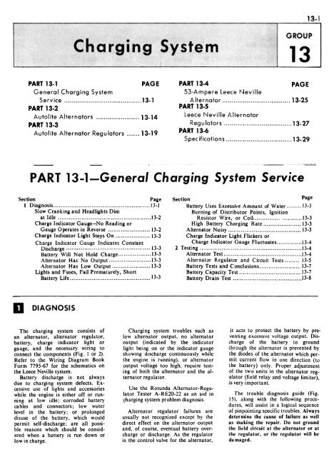
DIAGNOSIS<br />
The charging system consists of<br />
an alternator, alternator regulator,<br />
battery, charge indicator light or<br />
gauge, and the necessary wiring to<br />
connect the components (Fig. I or 2).<br />
Refer to the Wiring Diagram Book<br />
Form 7795-67 for the schematics on<br />
the Leece Neville system.<br />
Battery discharge is not always<br />
due to charging system defects. Excessive<br />
use of lights and accessories<br />
while the engine is either off or running<br />
at low idle; corroded battery<br />
cables and connectors; low water<br />
level in the battery; or prolonged<br />
disuse of the battery, which would<br />
permit self-discharge; are all possible<br />
reasons which should be considered<br />
when a battery is run down or<br />
low incharge.<br />
<strong>Charging</strong> system troubles such as<br />
low alternator output, no alternator<br />
output (indicated by the indicator<br />
light being on or the indicator gauge<br />
showing discharge continuously while<br />
the engine is running), or alternator<br />
output voltage too high, require testing<br />
of both the alternator and the alternator<br />
regulator.<br />
Use the Rotunda Alternator-Regulator<br />
Tester A-RE20-22 as an aid in<br />
s;harging system problem diagnosis.<br />
Alternator regulator failures are<br />
usually not recognized except by the<br />
direct effect on the alternator output<br />
and, of course, eventual battery overcharge<br />
or discharge. As the regulator<br />
is the control valve for the alternator,<br />
it acts to protect the battery by preventing<br />
excessive voltage output. Discharge<br />
of the battery to ground<br />
through the alternator is prevented by<br />
the diodes of the alternator which permit<br />
current flow in one direction (to<br />
the battery) only. Proper adjustment<br />
of the two units in the alternator regulator<br />
(field relay and voltage limiter),<br />
is very important.<br />
The trouble diagnosis guide (Fig.<br />
15), along with the following procedures,<br />
will assist in a logical sequence<br />
of pinpointing specific troubles. Always<br />
determine the cause of failure as well<br />
as making the repair. Do not ground<br />
the field circuit at the alternator or at<br />
the regulator, or the regulator will be<br />
damaged.
<strong>13</strong>-2 GROUP <strong>13</strong>-<strong>Charging</strong> <strong>System</strong><br />
SLOW CRANKING AND<br />
HEADLIGHTS DIM AT IDLE<br />
Refer to Fig. 15 for these symptoms.<br />
Using the Rotunda Battery Starter<br />
Tester, perform a Battery Capacity<br />
Test by loading the battery to three<br />
times its ampere hour rating for 15<br />
seconds. If the total battery voltage<br />
is less than 9.6 volts, check the specific<br />
gravity of each cell. If there is less than<br />
50 points (0.050) difference between<br />
cells, the battery is low in charge. If<br />
the specific gravity test shows more<br />
than 50 points between cells, the battery<br />
is defective. If battery voltage<br />
was above 9.6 volts, perform a Starter<br />
Cranking Circuit Test. Use any Rotunda<br />
voltmeter and measure the voltage<br />
drop in the four parts of the cranking<br />
circuit. If the voltage is greater than<br />
specified, the cable connections are corroded<br />
or the cables are defective. Clean<br />
the battery connections or replace battery<br />
cables.<br />
Check the drive belt for proper tension.<br />
Adjust it if necessary.<br />
Use any Rotunda voltmeter and<br />
perform a Battery Drain Test. Any<br />
voltage indicates the possibility of a<br />
regulator field relay closed, an alternator<br />
positive diode shorted, lighting or<br />
other circuit in continuous operation,<br />
or pinched or grounded wiring. Repair<br />
or replace parts as required.<br />
Use any Rotunda voltmeter to measure<br />
the alternator voltage output at<br />
2000 rpm. Set the voltage limiter to<br />
specification. If the owner used the vehicle<br />
for short trips or has extended<br />
periods at idle, set the voltage limiter<br />
to the high side of the specification.<br />
Using Rotunda equipment, perform<br />
the Alternator Output Test. Repair<br />
the alternator if necessary.<br />
Secure information from the customer<br />
concerning excessive use of accessories.<br />
Instruct the customer in proper<br />
usage of the battery.<br />
CHARGE INDICATOR GAUGE-<br />
NO READING OR GAUGE<br />
OPERATES IN REVERSE<br />
Refer to Fig. 15 for these symptoms.<br />
Either of two different type indicator<br />
gauges may be encountered. One<br />
type of gauge has external loops on<br />
the back of the gauge. The gauge<br />
wire is routed through these loops with<br />
no physical connection to the gauge.<br />
The other type gauge uses external<br />
terminal post connections. In this case,<br />
the gauge wire is connected to the terminal<br />
posts.<br />
To test the charge indicator gauge,<br />
turn the headlights ON with the engine<br />
off. The indicator pointer should<br />
move toward the D or discharge portion<br />
of the scale. The test for indication<br />
in the charge direction is made by<br />
first turning on the lights for about<br />
two minutes (engine not running), and<br />
then running the engine at about<br />
1500 rpm. Turn the lights off and<br />
observe the pointer travel. If charge is<br />
indicated, the indicator is satisfactory.<br />
If no movement of the needle is<br />
obtained, check the loop (or connections)<br />
on the rear of the gauge to<br />
see if the battery to alternator wire<br />
passes inside the loop (or the connections<br />
are tight). If the wire is in<br />
the loop (or the connections are
PART <strong>13</strong>-1-General <strong>Charging</strong> <strong>System</strong> Service <strong>13</strong>-3<br />
tight) and the gauge does not indicate<br />
a charge or discharge, the gauge<br />
is inoperative.<br />
If the pointer moves toward the C<br />
or charge portion of the scale when<br />
the headlights are first turned ON,<br />
the wire passes through the loop in<br />
the wrong direction (or the wire<br />
connections are reversed). Feed the<br />
wi re through the loop in the opposite<br />
direction (or reverse the wires<br />
on the terminals), observing the precaution<br />
of disconnecting the battery<br />
before working under the instrument<br />
panel.<br />
CHARGE INDICATOR LIGHT<br />
STAYS ON<br />
Refer to Fig. 15 for this symptom.<br />
Other symptoms covered under this<br />
heading are: charge indicator gauge<br />
indicates constant discharge; battery<br />
will not hold charge; alternator has<br />
no output; alternator has low output.<br />
Check for a broken, loose or slipping<br />
drive belt. Inspect battery, cables and<br />
charging system wiring for good electrical<br />
contact. Clean the battery terminals<br />
and tighten all connections as<br />
necessary. Check the battery specific<br />
gravity. Charge the battery and perform<br />
the battery tests. Replace the battery<br />
if necessary.<br />
If the owner has had previous difficulty<br />
with the battery running down<br />
and past history does not indicate that<br />
the problem is due to excessive night<br />
driving," excessive use of accessories,<br />
short trips or extended periods of idle,<br />
check the complete charging system.<br />
Use the Rotunda Alternator-Regulator<br />
Tester A-RE20-22 as an aid in<br />
charging system problem diagnosis.<br />
CHECK ALTERNATOR<br />
OUTPUT<br />
Test the alternator output at the<br />
battery (Section 2 Testing). With the<br />
ammeter in series between the battery<br />
cable and battery post, it is necessary<br />
to add 2 amperes to the output reading<br />
obtained to cover the current draw<br />
of the standard ignition system and 6<br />
amperes for the transistor ignition<br />
system.<br />
An output of 2 to 5 amperes less<br />
than that specified usually indicates<br />
an open diode. An output of approximately<br />
10 amperes less than that<br />
specified usually indicates a shorted<br />
diode.<br />
CHECK VOLTAGE LIMITER<br />
Check the voltage limiter setting,<br />
and check the closin2 volta2e of the<br />
field relay (the voltage at which the<br />
field relay contacts just make contact).<br />
Adjust the voltage limiter and/<br />
or the field relay if their settings are<br />
out of specification.<br />
On some cars the location of the<br />
regulator may prevent adjustment on<br />
the car. Remove the regulator to an<br />
alternator-regulator test stand if adjustment<br />
is necessary.<br />
The field relay used with the transistorized<br />
voltage regulator is a sealed<br />
unit and is not to be adjusted. To<br />
determine its closing voltage, follow the<br />
procedure given in Section 2 Testing,<br />
under Autolite Regulator and Circuit<br />
Tests.<br />
If the regulator was adjusted properly,<br />
check the green-red wire from<br />
the accessory terminal of the ignition<br />
switch through the charge indicator<br />
light and IS-ohm resistor to the<br />
voltage regulator, and the white-black<br />
wire from the voltage regulator to<br />
the alternator. Repair or replace as<br />
necessary.<br />
With the engine at 1000 rpm, the<br />
voltage produced at the ST A termin~l<br />
of the alternator should be 6<br />
volts or more. A voltage less than 6<br />
volts may be caused by an open<br />
negative diode.<br />
CHECK CHARGING<br />
CIRCUIT RESISTANCE<br />
Perform the Circuit Resistance Tests<br />
(Section 2 Testing). To check the battery<br />
to field wiring, connect the field<br />
rheostat between the battery positive<br />
terminal and the alternator FLD terminal<br />
and repeat the alternator output<br />
test. If the alternator now has<br />
good output the wire from the battery<br />
terminal of the starter relay to the FLD<br />
terminal of the alternator is defective.<br />
Failure to remo~e the regulator connector<br />
plug (or wire leads on Leece<br />
Ne~ille system), for this test will result<br />
in burned regulator contacts. If the<br />
alternator still has no output it is defective.<br />
Remove the alternator and perform<br />
the bench tests. Replace defective<br />
parts. Visually check the alternator<br />
to regulator harness for shorts to<br />
ground. caused by worn insulation<br />
or rubbed or pinched wires. Use the<br />
Rotunda Alternator Regulator Tester<br />
for the Autolite system.<br />
CHECK THE IS-OHM<br />
RESISTOR (VEHCILES WITH<br />
INDICATOR LIGHT)<br />
Disconnect the regulator terminal<br />
plug. Connect a No. 1155 bulb between<br />
the I terminal of the plug and<br />
ground. Turn the ignition switch on.<br />
If the 1155 bulb does not light, the<br />
15-ohm resistor is defective. Replace the<br />
resistor if it is defective.<br />
LIGHTS AND FUSES FAIL<br />
PREMATURELY, SHORT<br />
BA TTERY LIFE<br />
Refer to Fig. IS for these symptoms.<br />
Other symptoms covered under this<br />
heading are: battery uses excessive<br />
amount of water; burning of distlibutor<br />
points, ignition resistor wire, or<br />
coil; high battery charging rate.<br />
Visually check the alternator regulator<br />
mounting to the body, including<br />
the regulator ground wire at the regulator<br />
for loose or corroded connections.<br />
Clean and tighten connections and<br />
mountings.<br />
Use any Rotunda voltmeter measure<br />
alternator voltage output at<br />
20()() rpm. Adjust the voltage limiter<br />
or replace the regulator if it cannot<br />
be adjusted.<br />
ALTERNATOR NOISY<br />
Refer to Fig. 15 for this symptom.<br />
When investigating the complaint of<br />
alternator noise, first try to localize<br />
the noise area to make sure that the<br />
alternator is at fault rather than the<br />
alternator belt, water pump, or<br />
another part of the vehicle. Start the<br />
engine and use a stethoscope or similar<br />
sound detector instrument to localize<br />
the noise. An alternator bearing,<br />
water pump bearing or belt<br />
noise is usually evidenced by a<br />
squealing sound.<br />
An alternator with a shorted<br />
diode will normally whine (magnetic<br />
noise) and will be most noticeable<br />
at idle speeds. Perform the alternator<br />
output test. If the output is approximately<br />
10 amperes less than that<br />
specified, a shorted diode is usually<br />
indicated.<br />
To eliminate the belt(s) as the<br />
ca use of noise, check the belt(s) for<br />
bumps, apply a light amount of belt<br />
dressing to the belt(s). If the alterna<br />
tor belt is at fault, adjust the belt<br />
to specification, or replace the belt if<br />
necessary.<br />
If the belt(s) is satisfactory and<br />
the noise is believed to be in the alternator<br />
or water pump, remove the<br />
alternator belt. Start the engine and<br />
listen for the noise as a double check<br />
to be sure that the noise is not caused<br />
by another component. Use this test<br />
and the sound detector test to isolate<br />
the offending unit. If the noise is traced<br />
to the alternator, remove it and inspect<br />
the bearings for wear, shlift<br />
scoring, or an out-of-round condition.<br />
Visually inspect the alternlitor<br />
machined surfaces on both housings
<strong>13</strong>-4<br />
GROUP <strong>13</strong>-<strong>Charging</strong> <strong>System</strong><br />
and on the stator core. Check for improper<br />
assembly of core to housings. Repair<br />
or replace the alternator.<br />
CHARGE INDICATOR LIGHT<br />
FLICKERS OR CHARGE<br />
INDICATOR GAUGE<br />
FLUCTUATES<br />
Refer to Fig. 15 for this symptom.<br />
This condition may be caused by dirty<br />
or oxidized regulator contacts,<br />
loose or damaged connections in the<br />
charging system wiring harness, worn<br />
brushes, or improper brush tension.<br />
At certain engine speeds the ammeter<br />
needle will fluctuate to some<br />
degree when voltage regulation is<br />
just starting, and when the turn signals<br />
are in operation, which is normal.<br />
Use the Rotunda Volt-Amp-Alternator<br />
Tester and perform the alternator<br />
Circuit Resistance Tests. Resistance<br />
higher than that specified indicates<br />
loose connections or damaged wiring.<br />
Use any Rotunda voltmeter to measure<br />
the alternator voltage output at<br />
2000 rpm. Erratic voltage output<br />
indicates dirty or oxidized regulator<br />
contacts.<br />
Use the Rotunda Volt-Amp-Alternator<br />
Tester and perform a Transistor<br />
Regulator Field Relay Test. Observe<br />
for erratic operation of the relay.<br />
Remove the alternator, inspect the<br />
brush length and check the brush<br />
spring tension, and condition of the slip<br />
rings.<br />
Use any Rotunda voltmeter and<br />
measure the alternator stator neutral<br />
voltage. Voltage below specification<br />
indicates an open negative diode.<br />
TESTING<br />
ALTERNATOR TESTS<br />
Refer to Wiring Diagram Manual<br />
From 7795P-67 for locations of wiring<br />
harnesses. Schematics are shown<br />
in Group 19 of the manual. Use<br />
care when connecting any test equipment<br />
to the alternator system, as the<br />
alternator output terminal is connected<br />
to the battery at all ti meso<br />
ALTERNATOR OUTPUT<br />
TEST-ON ENGINE<br />
When the alternator output test is<br />
conducted off the car, a test bench<br />
must be used. Follow the procedure<br />
given by the test bench equipment<br />
manufacturer. When the alternator<br />
is removed from the car for this<br />
purpose always disconnect a battery<br />
cable as the alternator output connector<br />
is connected to the battery at<br />
all ti mes,<br />
To test the output of thc alternator<br />
on the car, proceed as follows:<br />
I. Place the transmission in neutral<br />
or park and apply the parking<br />
brake. Make the connections as<br />
shown in Fig. 3 or 4. Be sure tnat<br />
the field resistance control is at the<br />
OFF position at the start of this test.<br />
2. Close the battery adapter<br />
switch. Start the engine, then open the<br />
battery adapter switch.<br />
3. Increase the engine speed to<br />
approximately 2000 rpm. Turn off<br />
all lights and electrical accessories.<br />
4. Turn the field rheostat clockwise<br />
until 15 volts is indicated on the<br />
voltmeter. Turn the master control<br />
clockwise until the voltmeter indicates<br />
between II and 12 volts. Holding<br />
the master control in this position turn<br />
the field rheostat clockwise to its maximum<br />
rotation. Turn the master control<br />
counterclockwise until the voltmeter indicates<br />
15 volts. Observe the ammeter<br />
reading. Add 2 amperes to this read-<br />
ing when the car is equipped with standard<br />
ignition or 6 amperes with the<br />
transistor ignition system, to obtaIn<br />
total alternator output. If rated output<br />
cannot be obtained increase the<br />
engine speed to 2900 rpm and repeat<br />
this step.<br />
5, Return the field resistance control<br />
to the maximum counterclockwise<br />
position,release the master control,<br />
and stop the engine. Disconnect<br />
the test equipment, if no further tests<br />
are to be made.<br />
An output of 2 to 5 amperes below<br />
specifications usually indicates<br />
an open diode rectifier. An output of<br />
approximately 10 amperes below<br />
specifications usually indicates a<br />
shorted diode rectifier. An alternator<br />
with a shorted diode will usually<br />
whine, which will be most noticeable<br />
at idle speed.<br />
AUTOLITE<br />
NEUTRAL<br />
TEST-ON<br />
STATOR<br />
VOLTAGE<br />
ENGINE<br />
The Autolite alternator ST A terminal<br />
is connected to the stator coil<br />
neutral or center point (see Figs. 1<br />
and 2). The voltage generated at this<br />
point is used to close the field relay<br />
in the charge indicator light system.<br />
To test for the stator neutral voltage.<br />
connect the voltmeter positive<br />
lead to the ST A terminal and connect<br />
the negative lead to ground.<br />
Start the engine and run it at 1000<br />
rpm. Turn off all lights and accessories.<br />
The voltage indicated on the<br />
meter should be 6 volts or more.<br />
FIELD OPEN OR SHORT<br />
CIRCUIT TEST-ON BENCH<br />
Make the connection as shown in<br />
Figs. 3 or 4. The current draw, as indicated<br />
by the ammeter, should be to<br />
specifications. If there is little or no<br />
current flow, the field or brushes have<br />
a high resistance or are open. A current<br />
flow considerably higher than<br />
that specified above, indicates shorted<br />
or grounded turns or brush leads<br />
touching. If the test showns that the<br />
field is shorted or open and the field<br />
brush assembly or slip rings are not<br />
at fault, the entire rotor must be<br />
replaced.<br />
If the alternator has output at low<br />
rpm and no output at high rpm,<br />
centrifugal force may be causing the<br />
rotor windings to short to ground.<br />
Put the alternator on a test stand<br />
and repeat the preceding test. Run<br />
the alternator at high speed during<br />
the test.<br />
DIODE TEST-ON<br />
BENCH<br />
Disassemble the alternator and<br />
disconnect the diode assembly from<br />
the stator and make the test connections<br />
as shown in Figs. 5 or 6.<br />
To test the negative diodes contact<br />
one probe to the diode plate as<br />
shown and contact each of the three<br />
stator lead terminals with the other<br />
probe. Reverse the probes and repeat<br />
the test. Test the positive diodes<br />
in the same way.<br />
All of the diodes should show a<br />
low reading of approximately 60<br />
ohms in one direction and infinite<br />
reading (no needle movement) with<br />
the probes reversed. Be sure to use<br />
the Rotunda ohmmeter with the<br />
multiply-by knob at 10.<br />
OPEN OR GROUNDED<br />
STATOR COIL TESTS-<br />
ON BENCH<br />
These tests are made to verify<br />
that the stator coil is defective. Disassemble<br />
the stator from the alternator<br />
and rectifier assembly for<br />
these tests.
PART <strong>13</strong>-1-General <strong>Charging</strong> <strong>System</strong> Service <strong>13</strong>-5<br />
~ , 00<br />
~"'"<br />
.<br />
""..0<br />
- o.<br />
.~~<br />
Yello,"<br />
IS3,=,<br />
. -,0-,<br />
r,;.-:..<br />
~..<br />
~,., ..<br />
i~~1<br />
m~~~@@~~<br />
~- ,-<br />
r~<br />
-REGULATOR<br />
CONNECTOR<br />
Green<br />
INSERT SPADE<br />
LUGS IN THE A<br />
F<br />
"~ṟ<br />
- ~<br />
"-48<br />
+<br />
~<br />
'Red<br />
Black<br />
t<br />
"'--W<br />
ALTERNATOR<br />
BATTERY<br />
OUTPUT TEST<br />
FIELD DPEN DR SHORT CIRCUIT TEST<br />
J<strong>13</strong>56.B<br />
FIG. 3.<br />
Alternator Tests.<br />
Autolite<br />
Open Stator Test-On Bench should not show any continuity, if it<br />
does, the stator winding is grounded<br />
and must be replaced.<br />
Set the Rotunda ohmmeter multiply-by<br />
knob at 1. Connect the ohmmeter<br />
between each pair of stator<br />
leads. If the ohmmeter does not show<br />
equal readings between each pair of<br />
stator leads, the stator is open and<br />
must be replaced.<br />
Grounded Stator Test-On<br />
Bench<br />
Set the Rotunda ohmmeter multiply-by<br />
knob at 1000. Connect the<br />
ohmmeter between one of the stator<br />
leads and the stator core. Be sure that<br />
the test lead makes a good electrical<br />
connection to the core. The ohmmeter<br />
ALTERNATOR REGULATOR<br />
AND CIRCUIT TESTS<br />
CIRCUIT<br />
TESTS<br />
RESISTANCE<br />
For the purpose of this test, the resistance<br />
values of the circuits have<br />
been converted to voltage drop readinl!s<br />
for a current flow of 20 amperes.<br />
Alternator to Battery Positive<br />
Terminal<br />
To check the alternator to battery<br />
ground terminal voltage drop, make<br />
the connections as shown in Fig. 7 or 8.<br />
Turn off all electrical accessories and<br />
lights. Close the battery adapter<br />
switch, start the engine, then open the<br />
battery adapter switch. Increase the<br />
engine speed to 2000 rpm. Adjust the<br />
field rheostat until the ammeter indicates<br />
20 amperes. Note the voltmeter<br />
reading at this point. The voltage<br />
reading should be no greater than<br />
0.3 volt on a car with a charge indicator<br />
light and 0.5 volt on a car with<br />
an ammeter.<br />
These voltage drops have been computed<br />
for a standard car. The current<br />
used by any auxiliary, continously<br />
operating. heavy-duty equipement<br />
will not show on the ammeter and will<br />
nave to be taken into account when<br />
makin~ this test.
FIELD OPEN OR SHORT CIRCUIT TEST<br />
J<strong>13</strong>88<br />
FIG. 4 .Alternator Tests -Leece Neville<br />
Alternator<br />
Terminal<br />
to Battery Ground<br />
To check the alternator to battery<br />
positive terminal voltage drop, make the<br />
connections as shown in Fig. 7 or 8.<br />
Close the battery adapter switch, start<br />
the engine and open the adapter switch.<br />
Maintain the engine speed at 2000<br />
rpm. Adjust the field rheostat until the<br />
ammeter indicates 20 amperes. The<br />
voltage indicated on the voltmeter<br />
should be less than 0.1 volt.<br />
REGULATOR TESTS<br />
Voltage Limiter Te.t<br />
Voltage limiter calibration tests<br />
must be made with the regulator cover<br />
in place and the regulator at normal<br />
operating temperature (equivalent<br />
to the temperature after 20 minutes<br />
of operation on the car with the hood<br />
down).<br />
For accurate voltage limiter testing,<br />
the battery specific gravity must<br />
be at least 1.225. I f the battery is<br />
low in charge. either charge it to<br />
1.225 specific gravity or substitute a<br />
fully charged battery, before making<br />
a voltage limiter test.<br />
To test the voltage regulator on<br />
the car. make the test connections<br />
to the battery as shown in Fig. 9.<br />
Turn all accessories off, including<br />
door operated domc lights. Close the<br />
battery adllpter switch. stllrt thc cn.<br />
sine. then open the adapter swit£h.<br />
Attach a voltage regulator thcrmo.<br />
meter to the regualtor cover. Operate<br />
the engine at approximately 2000<br />
rpm for an additional 5 minutes.<br />
When the battery is charged, and<br />
the voltage regulator has been temperature<br />
stabilized, the ammeter<br />
should indicate less than 10 amperes<br />
with the master control set at the<br />
1/4-0HM position.<br />
Cycle the regulator as follows<br />
(mechanical regualtors only): turn<br />
the ignition key to OFF to stop the<br />
engine, close the adapter switch,<br />
start the engine, and open the adapter<br />
switch. Increase the engine speed to<br />
2000 rpm. Allow the battery to normalize<br />
for about one minute, then<br />
read the voltmeter. Read the thermometer,<br />
and compare the voltmeter reading<br />
with the voltage given in Fig. 10 for<br />
the ambient temperature indicated on<br />
the thermometer. I f the regulated voltaRe<br />
is not within specifications, remove
PART <strong>13</strong>-1-General <strong>Charging</strong> <strong>System</strong> Service <strong>13</strong>-7<br />
FIG. 5-Autolite<br />
--"'~-<br />
DIODE<br />
PLATE J 1211-!)<br />
Diode Test<br />
CONTACT CONTACT EACH<br />
HEA T SINK DIODE TERM1NAL J 1262-D<br />
FIG. 6-53-Ampere Leece Neville<br />
Diode Test<br />
the regulator to an alternator regulator<br />
test stand and make a voltage<br />
limiter adjustment (Part <strong>13</strong>-3). After<br />
each adjustment, be sure to cycle the<br />
regulator before each reading (mechanical<br />
regulator only). The readings<br />
must be made with the cover in place<br />
(mechanical regulator only).<br />
On some cars the location of the<br />
regulator may prevent adjustment on<br />
the car. Remove the regulator to an<br />
alternator-regualtor test stand if adjustment<br />
is necessary.<br />
Field<br />
Regulator<br />
Relay<br />
Test-Mechanical<br />
Remove the regulator from the car,<br />
and remove the regulator cover. Make<br />
the connections as shown in Fig. II or<br />
12. Slowly rotate the field rheostat<br />
control clockwise from the maximum<br />
counterclockwise position until the<br />
field relay contacts close. Observe the<br />
voltmeter reading at the moment that<br />
the relay contacts close. This is the relay<br />
closing voltage. If the relay closes<br />
immediately, even with the field rheostat<br />
close to the maximum counterclockwise<br />
position, push the red button<br />
between the two meters, and repeat the<br />
test. If the closing voltage is not to<br />
specifications, adjust the relay (Part<br />
<strong>13</strong>-3).<br />
Field<br />
Regulator<br />
Relay<br />
Test<br />
- Transistor<br />
Disconnect the relay connector plug.<br />
Make the connections as shown in Fig.<br />
II. Slowly rotate the field rheostat<br />
control clockwise from the maximum'<br />
counterclockwise position until the test<br />
light comes on. Observe the voltmeter<br />
reading at the moment that the light<br />
comes on. This is the relay closing<br />
voltage. If the relay closes immediately,<br />
even with the field rheostat<br />
close to the maximum counterclockwise<br />
position, push the red button between<br />
the two meters, and repeat the<br />
test. If the closing voltage is not to<br />
specification, replace the relay.<br />
BATTERY TESTS AND<br />
CONCLUSIONS<br />
Tests are made on a battery to determine<br />
the state of charge and also<br />
the condition. The ultimate result of<br />
these tests is to show that the battery<br />
is good, needs recharging, or must be<br />
replaced.<br />
If a battery has failed, is low in<br />
charge, or requires water frequently,<br />
good service demands that the reason<br />
for this condition be found. It<br />
may be necessary to follow trouble<br />
shooting procedures to locate the<br />
cause of the trouble (Section I in this<br />
part).<br />
Hydrogen and oxygen gases are<br />
produced during normal battery operation.<br />
This gas mixture can explode<br />
if flames or sparks are brought<br />
near the vent openings of the battery.<br />
The sulphuric acid in the battery electrolyte<br />
can cause a serious burn if<br />
spilled on the skin or spattered in the<br />
eyes. It should be flushed away with<br />
large quantities of clear water.<br />
Before attempting to test a battery,<br />
it IS Important that It be given a<br />
thorough visual examination to determine<br />
if it has been damaged. The presence<br />
of moisture on the outside of the<br />
case and/or low electrolyte level in one<br />
or more of the cells are indications of<br />
possible battery damage.<br />
The Rotunda batteries incorporate<br />
a single one-piece cover which completely<br />
seals the top of the battery<br />
and the individual cell connectors.<br />
This cover must not be pierced with<br />
test probes to perform individual cell<br />
tests. The Rotunda Cell Analyzer (S-<br />
RECA-200) measures the individual<br />
cell voltages by inserting probes into<br />
the cell openings. Follow the instructions<br />
that come with the unit.<br />
A battery can also be tested by<br />
determining its ability to deliver current.<br />
This may be determined by conducting<br />
a Battery Capacity Test.<br />
Fig. <strong>13</strong> shows the battery capacity<br />
test in outline form.<br />
BAlTERY<br />
CAPACITY TEST<br />
A high rate discharge tester (Battery-Starter<br />
Tester) in conjunction with<br />
a voltmcter is used for this test.<br />
I. Turn the control knob on the<br />
Battery-Starter Tester to the OFF<br />
positioll.<br />
2. Turn the voltmeter selector<br />
s~itch to the 20-volt position.<br />
3. Connect both positive test leads<br />
to the positive battery post and both<br />
negative test leads to the negative<br />
ba ttery post. The yoltmeter clips<br />
must contact the battery posts and<br />
not the high rate discharge tester<br />
cli ps. Unless this is done the actual<br />
battery terminal yoltage ~ill not be<br />
indicated.<br />
4. Turn the load control knob in<br />
a clol:kwise direction until the ammeter<br />
reads three times the ampere<br />
hour rating of the battery. (A 45<br />
ampere-hour battery should be tested<br />
at <strong>13</strong>5 amperes load).<br />
5. With the ammeter reading the
deR.<br />
PART <strong>13</strong>-1-General <strong>Charging</strong> <strong>System</strong> Service <strong>13</strong>-9<br />
YELLOW<br />
I GREEN<br />
YELLOW<br />
-<br />
ATOR<br />
~<br />
ATOF<br />
';/1 . , -., . -.<br />
RELAY<br />
Green.<br />
oJ.<br />
,~"V'-",<br />
Green<br />
r""~<br />
REMOVE BAT. AND<br />
FLD. REGULATOR<br />
WIRES AND CONNECT<br />
CLIPS TO WIRES<br />
Red<br />
WIRES AND<br />
otINECT CL,<br />
TO WIRES<br />
\\'<br />
,<br />
Black<br />
+<br />
Yellow<br />
\\<br />
ALTERNATOR<br />
I<br />
BATTERY , I<br />
BATTERY<br />
,<br />
OUTPUT TERMINAL<br />
OOTPUT TERMINAL<br />
Ii<br />
I~<br />
..<br />
ALTERNATOR<br />
~<br />
~<br />
VOL TAGE DROP TEST-<br />
ALTERNATOR TO BATTERY POSITIVE TERMINAL<br />
VOL T AGE DROP TEST-<br />
AL TERNATOR TO BATTERY GROUND TERMINAL<br />
FIG. 8-Circuit<br />
Resistance Tests- Leece Neville 53-Ampere<br />
1<strong>13</strong>89-A<br />
ble and connect the positive lead of<br />
a voltmeter to the cable. Connect the<br />
negative lead of the voltmeter to the<br />
battery negative post.<br />
With all circuits off, the meter<br />
should read zero. Any battery exter-<br />
nal load will cause the voltmeter to<br />
read full battery voltage.<br />
If the car is equipped with an electric<br />
clock, momentarily connect the bat.<br />
tery ground cable to the battery negative<br />
post to make certain that the<br />
clock is wound. When the clock runs<br />
down at the end of approximately 2<br />
minutes the voltmeter will show full battery<br />
voltage.
<strong>13</strong>.10 GROUP <strong>13</strong>-<strong>Charging</strong> <strong>System</strong><br />
Yellow<br />
" ...<br />
Green<br />
'"<br />
~<br />
. "'-<br />
REGULATOR<br />
yretaB Adapter -- r ,.,<br />
Switch<br />
Red<br />
'\ \\ -+<br />
" . .<br />
'~<br />
"'1<br />
'(<br />
/ /<br />
-- BATTERY<br />
TERNATOR<br />
FIG. 9.<br />
AUTOLITE<br />
Voltage limiter Tests-Typical<br />
LEECE NEVILLE 53.AMPERE<br />
J<strong>13</strong>90.A<br />
Ambient Air<br />
Temperature 0 F<br />
50<br />
75<br />
100<br />
125<br />
Setting<br />
Voltage<br />
Limiter<br />
(Volts)<br />
14.1-15.1<br />
<strong>13</strong>.9-14.9<br />
<strong>13</strong>.7-14.7<br />
<strong>13</strong>.6-14.6<br />
J <strong>13</strong>54.A<br />
FIG. la-Voltage Limiter Setting<br />
Versus Ambient Air Temperature<br />
(Mechanical or Transistor<br />
Regulator)
PART <strong>13</strong>-1-General <strong>Charging</strong> <strong>System</strong> Service <strong>13</strong>-1<br />
MECHANICAL REGULATOR<br />
TRANSISTOR REGULATOR<br />
FIG. 7 7-Field Relay Test-Autolite<br />
Regulators<br />
J<strong>13</strong>79.A<br />
.~RHEOSTAT<br />
FIELD CONTROL<br />
LEADS~..<br />
VOLTAGE LIMITER FIELD<br />
~ ~ , RELAY<br />
\"<br />
I, ~g!J<br />
~<br />
o.<br />
'c."<br />
~<br />
I<br />
VOLTMETER<br />
. NEGA TIVE LEAO<br />
i J<br />
VOLTMETER<br />
POSITIVE LEAD<br />
"e"<br />
"';:::::<br />
~<br />
BATTERY<br />
AMMETER CIRCUIT<br />
J <strong>13</strong>80-A<br />
FIG. 72-Field Relay Test. Leece Neville Requlators
<strong>13</strong>-12 GROUP <strong>13</strong>-<strong>Charging</strong> <strong>System</strong><br />
BATTERY CAPACITY TEST<br />
ADJUST RESISTANCE UNTIL AMMETER READS J TIMES AMPERE-HOUR<br />
RATING OF BATTERY. HOLD FOR 15 SECONDS AND NOTE VOLTAGE.<br />
VOLTAGE OVER 9.6<br />
VOLTAGE LE.c;~ THAN 9.6<br />
CHECK SPECIFIC GRAVITY. CHARGE BATTERY.<br />
IF BELOW 1.230. OTHERWISE BATTERY IS O.K.<br />
(CHFCK ~PFCIFIC GRAVITY OF ~ACH CFul<br />
LESS THAN SO POINT.<br />
(0.050) BETWEEN CELLS<br />
ADD WATER IF NECESSARY AND CHARGE BATTERY PER<br />
CHARGING SCHEDULE AND REPEAT CAPACITY TEST<br />
I I I<br />
TOTAL VOLTAGE<br />
TOTAL VOLTAGE<br />
LESS THAN 9.6 MORE T~AN 9.6<br />
(REPLACJ BATTERYI<br />
I BATTERY IS ~ERVICEABLEI<br />
Jl039.D<br />
FIG. <strong>13</strong>-<br />
Battery Capacity Test Outline<br />
Spec ific<br />
Gravity<br />
Reading<br />
1.125-1.150Q)<br />
1.150-1.175<br />
1.175-1.200<br />
1.200-1.225<br />
Above 1.225<br />
Charge<br />
Rate<br />
Amperes<br />
35<br />
35<br />
35<br />
35<br />
'i<br />
Battery Co pac ity - Ampere<br />
Hours<br />
45 55 70 80 85<br />
65 min. I 80 min. 1100 min. 115 min. 125 min.<br />
50 min. I 65 min.<br />
40 min. I 50 min.<br />
80 min.<br />
60 min.<br />
95 min.<br />
70 min.<br />
105 min.<br />
75 min.<br />
30 min. I 35 min.<br />
0 ~<br />
45 min.<br />
-~<br />
50 min.<br />
PART <strong>13</strong>-1-General <strong>Charging</strong> <strong>System</strong> Service <strong>13</strong>-<strong>13</strong><br />
SLOW CRANKING AND<br />
HEADLIGHTS DIM AT IDLE<br />
1. Battery low in charge.<br />
2. Defective battery.<br />
3. Corroded battery cables.<br />
4. Loose alternator drive belt.<br />
S. Continuous drain on battery<br />
6. Alternator regulator<br />
Ii miter out of adjustment.<br />
7. Defective alternator.<br />
8. Customer battery usage<br />
voltage<br />
CHARGE INDICATOR GAUGE<br />
SHOWS NO READING OR<br />
GAUGE OPERATES IN<br />
REVERSE<br />
1. Incorrect or no connections to<br />
gau,~e.<br />
2. Defective gau~e<br />
CHARGE INDICATOR LIGHT<br />
STAYS ON OR CHARGE<br />
INDICATOR GAUGE INDICATE~<br />
CONSTANT DISCHARGE<br />
1. Loose or broken drive belt.<br />
Z. Loose connections, or broken<br />
wires.<br />
3. Regulator voltage limiter or<br />
field relay out of adjustment or defective<br />
regulator.<br />
4. Grounded wiring from alterna<br />
tor to regulator.<br />
5. Open 15-ohm resistor across<br />
charge indicator light.<br />
6. Defective alternator.<br />
LIGHTS AND FUSES FAIL<br />
PREMATURELY, SHORT<br />
SA TTERY LIFE, SA TTERY<br />
USES EXCESSIVE WATER<br />
Loose or corroded connections 2. Hi,~h voltage limiter setting<br />
AI,~~RNA TOR NOISY<br />
I. Loose or bumpy belt.<br />
2. Noisy alternator bearing<br />
3. Shorted alternator diode<br />
4. Alternator stator core cocked in<br />
housings.<br />
CHARGE INDICATOR LIGHT<br />
FLICKERS OR CHARGE<br />
INDICA TOR GAUGE<br />
FLUCTUA<br />
TES<br />
1. Loose or damaged connections<br />
or wiring.<br />
2. Dirty or oxidized alternator<br />
regulator contacts (mechanical regulator).<br />
3. Defective field relay (transis-<br />
tor regulator).<br />
4. Worn alternator field brushes<br />
or slip rings or improper brush spring<br />
tension.<br />
S. Open circuit alternator negative<br />
diode.<br />
CHARGE INDICATOR LIGHT<br />
DOES NOT LIGHT WHEN<br />
IGNITION SWITCH IS<br />
TURNED ON<br />
1. Burned out charge indicator<br />
bulb.<br />
2. Defective wiring.<br />
3. Defective alternator regulator.<br />
FIG. 15.<br />
,<strong>Charging</strong> <strong>System</strong> Trouble Diagnosis Guide
1 Description and Operation<br />
<strong>13</strong>-14<br />
3-2-<br />
Section<br />
2 Common Adjustments and Repairs<br />
Page Section<br />
<strong>13</strong>-14 3 Removal and Installation,<br />
<strong>13</strong>-14 4 Major Repair Operations<br />
Page<br />
<strong>13</strong>-14<br />
<strong>13</strong>-16<br />
DESCRIPTION AND OPERATION<br />
The alternator charging system<br />
is a negative (-) ground system, and<br />
consists of an alternator, a regulator,<br />
a charge indicator, a storage battery<br />
and associated wiring. Refer to<br />
Wiring Diagram Manual Form<br />
7795P-67 for locations of wiring<br />
harnesses. Schematics are shown in<br />
Group 19 of this manual.<br />
ALTERNATOR<br />
The alternator is belt driven from<br />
the engine. The mechanical construction<br />
of the alternator differs from a<br />
generator in that the field rotates, and<br />
the generating windings are stationary.<br />
Energy is supplied from the alternator-regulator<br />
system to the rotating<br />
field through two brushes to two slip<br />
rings. The slip rings are mounted on<br />
the rotor shaft (Fig. 4), and are connected<br />
to the field coil.<br />
The alternator produces power in<br />
the .form of alternating current. The<br />
alternating current is rectified to direct<br />
current by six diodes (Fig. 7) for<br />
use in charging the battery and supplying<br />
power to the electrical system.<br />
COMMON ADJUSTMENTS AND<br />
REPAIRS<br />
BELT ADJUSTMENT.<br />
ALTERNATOR<br />
I. Loosen the alternator mounting<br />
bolt to a snug position and the<br />
adjusting arm bolts.<br />
2. Apply pressure on the alternator<br />
front housing only and tighten the<br />
adjusting arm to alternator bolt.<br />
3. Check the belt tension using<br />
tool T63L-8620-A. Adjust the belt<br />
for specified tension.<br />
4. Tighten aN mounting bolts.<br />
REMOVAL AND INSTAllATION<br />
REMOV AL EXCEPT COUGAR on the alternator front housing only, 6. Disconnect the leads and clip<br />
when tightening the belt. Tighten the and remove the alternator.<br />
adjusting arm bolts and the mounting<br />
bolt.<br />
4. Lower the car and connect the<br />
battery ground cable.<br />
INSTAllATION COUGAR<br />
1. Disconnect the battery ground<br />
cable, then raise the car on a hoist.<br />
2. L,oosen the alternator mounting<br />
bolts and remove the adjustment<br />
arm to alternator bolt.<br />
3. Disengage the alternator belt.<br />
Remove the alternator mounting bolt,<br />
disconnect the alternator wiring harness<br />
and remove the alternator.<br />
INSTAllATION<br />
EXCEPT COUGAR<br />
I. Attach the alternator wiring<br />
harness (Fig. I or 2). Position the alternator<br />
to the engine, and install the<br />
alternator mounting-bolt finger-tight.<br />
2. Install the adjustment arm to<br />
alternator bolt.<br />
3. Adjust the belt tension using<br />
tool T63L-8620-A. Apply pressure<br />
REMOV AL<br />
COUGAR<br />
I. Disconnect the battery ground<br />
cable.<br />
2. Remove the alternator adjusting<br />
arm bolt.<br />
3. Remove the ground wire bolt<br />
from the cylinder block.<br />
4. Open the clip on right fender<br />
apron retaining the alternator harness.<br />
5. Remove the alternator mounting<br />
bolt and spacer. Position the belt<br />
off the pulley and lay the alternator<br />
on top of the fender.<br />
I; Lay the alternator on top of the<br />
fender and connect the leads (Fig. 3).<br />
2. Position the alternator to the<br />
block and install the mounting bolt<br />
and spacer finger tight. Position the<br />
belt on the pulley.<br />
3. Position the ground wire to<br />
the block and install the ground wire<br />
bolt.<br />
4. Install the adjusting arm bolt<br />
finger tight, adjust the belt tension<br />
and tighten the bolts.<br />
5. Install the wire harness in the<br />
fender clip, connect the battery, and<br />
check the alternator ooeration.
~<br />
PART <strong>13</strong>-2-Autolite Alternators <strong>13</strong>-15<br />
Block<br />
BAT<br />
--.1 r'<br />
Black-Red Stripe<br />
-<br />
White<br />
FLD<br />
Block<br />
BAT<br />
,~ h<br />
~<br />
ft<br />
~<br />
BAT<br />
=)"<br />
--~<br />
j:j<br />
/ < ~<br />
tQ~<br />
,<br />
/<br />
Btac"-R~d StriPe~\<br />
FLD<br />
&<br />
FIG. 2-Mustang<br />
1Ft<br />
'"""Black.Red<br />
, MUSTANG 289 V-8<br />
White<br />
FLD<br />
Stripe<br />
Alternator Connections<br />
\J<br />
MUSTANG 200 SIX<br />
r<br />
--:D<br />
J<strong>13</strong>68-A
MAJOR REPAIR OPERATIONS<br />
DISASSEMBLY<br />
Fig. 4 shows a disassembled view<br />
of the Ford alternator.<br />
I. Mark both end housings and<br />
the stator with a scribe mark for assembly.<br />
2. Remove the three housing<br />
through bolts.<br />
3. Separate the front end housing<br />
and rotor from the stator and rear end<br />
housing.<br />
4. Remove all the nuts and wash-<br />
ers from the rear end housing and<br />
remove the rear end housing from the<br />
sta tor and diode plate assembly.<br />
S. Remove the brush holder mounting<br />
screws and remove the holder,<br />
FIG. 4-Disassembled Alternator<br />
J1166-E
PART <strong>13</strong>-2-Autolite Alternators <strong>13</strong>- 1 7<br />
~f'BW"'O'O"<br />
Stiff Wi,@<br />
FIG. 5<br />
.Pulley Removal<br />
brushes, brush springs, insulator and<br />
terminal.<br />
6. If replacement is necessary,<br />
press the bearing from the rear end<br />
housing, supporting the housing on<br />
the inner boss.<br />
7. If the diode plate assembly is<br />
being replaced, unsolder the stator<br />
leads from the printed-circuit board<br />
terminals, and separate the stator<br />
from the diode plate assembly. Use<br />
a lOO-watt soldering iron.<br />
8. If the printed-circuit board is<br />
being replaced, cut the printed-circuit<br />
board into six separate pieces and<br />
unsolder each piece from the diode it<br />
is attached to. Remove and discard the<br />
roll pins from the diode plates.<br />
9. Remove the drive pulley nut,<br />
lockwasher, pulley, fan, fan spacer,<br />
rotor and rotor stop (Fig. 5).<br />
10. Remove the three screws that<br />
hold the front end bearing retainer,<br />
and remove the retainer. Support the<br />
housing close to the bearing boss,<br />
and press out the old bearing from the<br />
housing, only if the bearing is defective<br />
or has lost its lubricant.<br />
11. Perform a diode test and a<br />
field open or short circuit test (Part<br />
<strong>13</strong>-1).<br />
CLEANING AND INSPECTION<br />
1. The rotor. stator and bearings<br />
must not be cleaned with solvent. Wipe<br />
these parts off with a clean cloth.<br />
2. Rotate the front bearing on<br />
the drive end of the rotor drive shaft.<br />
Check for any scraping noise, looseness<br />
or roughness that will indicate<br />
that the bearing is excessively worn.<br />
Look for excessive lubricant leakage.<br />
If any of these conditions exist, replace<br />
the bearing.<br />
3. Inspect the rotor shaft at the<br />
rear bearing surface for roughness<br />
or severe chatter marks. Renlace the<br />
I BRUSH<br />
TERMINAL<br />
BRUSH<br />
INSULATOR<br />
TERMINAL---' 10329<br />
3792S1.S<br />
J 1203.C<br />
FIG. 6-Brush<br />
FIG. 7<br />
Holder Assembly<br />
P~F~C; FI~MILY AGAINST HOUSING<br />
-Brush Leod Positions<br />
rotor assembly if the shaft is not<br />
smooth.<br />
4. Place the rear end bearing on<br />
the slip-ring end of the shaft and rotate<br />
the bearing on the shaft. Make<br />
the same check for noise, looseness<br />
or roughness as was made for the<br />
front bearing. Inspect the rollers and<br />
cage for damage. Replace the bearing<br />
if these conditions exist, or if the<br />
lubricant is lost or contaminated.<br />
S. Check the pulley and fan for<br />
excessive looseness on the rotor shaft.<br />
Replace any pulley or fan that is<br />
loose or bent out of shape. Check the<br />
rotor shaft for stripped or damaged<br />
threads. Inspect the hex hole in the<br />
end of the shaft for damage.<br />
6. Check both the front and rear<br />
housings for cracks. Check the front<br />
housings for stripped threads in the<br />
mounting ear. Replace defective housings.<br />
7. Check all wire leads on both<br />
the stator and rotor assemblies for<br />
loose soldered connections, and for<br />
burned insulation. Resolder poor connections.<br />
Replace parts that show<br />
burned insulation.<br />
8. Check the slip rings for nicks<br />
FIG.B-<br />
and surface roughness. Nicks and<br />
scratches may be retfioved by turning<br />
down the slip rings. Do not go<br />
beyond 1 he minimum diameter limit<br />
of 1.22 inches. If the slip rings are<br />
badly damaged, the entire rotor will<br />
have to be replaced, as it is serviced<br />
as a complete assembly.<br />
9. Replace any parts that are<br />
burned or cracked. Replace brushes<br />
and brush springs that are not to<br />
specification. The diode plate assembly<br />
is serviced as an assembly. However<br />
the printed circuit board is serviced<br />
separately.<br />
ASSEMBLY<br />
1. Press the front end bearing in<br />
the bearing boss (put pressure on the<br />
outer bearing only), and install the<br />
bearing retainer.<br />
2. If the stop-ring on the rotor<br />
drive shaft was damaged. install a<br />
new stop-ring. Push the new ring on<br />
the shaft and into the groove. Do not<br />
open the ring with snap ring pliers as<br />
permanent damage will result.<br />
3. Position the rotor stop on the<br />
drive shaft with the recessed side<br />
against the stop-ring.<br />
4. Position the front end housing,<br />
fan spacer, fan, pulley and lock<br />
washer on the drive shaft and install<br />
the retaining nut (Fig. 4), to specified<br />
torque.
<strong>13</strong>-1 8<br />
GROUP <strong>13</strong>-<strong>Charging</strong> <strong>System</strong><br />
FIG. 9- Alternator Terminal<br />
locations<br />
5. If the rear end housing bearing<br />
was removed, support the housin.g<br />
on the inner boss and press in a new<br />
bearing flush with the outer end surface.<br />
6. Place the brush springs,<br />
brushes, brush terminal and terminal<br />
insulator in the brush holder and hold<br />
the brushes in position by inserting a<br />
piece of stiff wire in the brush holder<br />
as shown in Fig. 6.<br />
7. Position the brush holder assembly<br />
in the rear end housing and<br />
install the mounting screws. Position<br />
the brush leads in the brush holder<br />
as shown in Fig. 7.<br />
8. If a new diode plate or printed<br />
circuit board is being installed. position<br />
the diode plate so that the<br />
diode leads go through the three<br />
holes in the printed-circuit board. Install<br />
the terminal bolt and insulator.<br />
Install new roll pins to maintain the<br />
1/2-inch insulator spacing between<br />
the printed-circuit board and the<br />
diode plate. Install a solder ring, then<br />
a small tinned washer on each diode<br />
lead and solder the diode leads to the<br />
printed-circuit board. Use a 100-<br />
watt iron. Avoid excess heat on the<br />
printed-circuit board so as not to<br />
loosen the printed-circuit wiring from<br />
the board. .<br />
9. Wrap the three stator winding<br />
leads around the printed-circuit board<br />
terminals and solder them. Use a 100-<br />
watt soldering iron and rosin-core<br />
solder. Position the stator neutral lead<br />
eyelet on the stator terminal insulators<br />
(Fig. 8). Position the diode assembly<br />
(Fig. 8).<br />
10. Install the ST A and BAT terminal<br />
insulators (Fig. 8). Position the<br />
stator and diode plate assembly in<br />
the rear end housing. Position the<br />
ST A (black), BAT (red) and FLD<br />
(white) insulators, on the terminal<br />
bolts, and install five retaining nuts<br />
(Fig. 9).<br />
11. Wipe the rear end beanng<br />
surface of the rotor shaft with a<br />
clean lint-free rag.<br />
12. Position the rear end housing<br />
and stator assembly over the rotor<br />
and align the scribe marks made<br />
during disassembly. Seat the machined<br />
portion of the stator core into<br />
the step in both end housings. Install<br />
the housing through bolts. Remove<br />
the brush retracting rod, and put a<br />
daub of waterproof cement over the<br />
hole to seal it.
1 Description and Operation<br />
2 Regulator Adjustments<br />
3 lotors<br />
<strong>13</strong>-19<br />
Section<br />
Mechanical Voltage Regulator ...<br />
Transistorized Voltage Regulator<br />
Page<br />
<strong>13</strong>..19<br />
,<strong>13</strong>-19<br />
,<strong>13</strong>-19<br />
,<strong>13</strong>-20<br />
Section<br />
Mechanical Regulator Adjustments ...<br />
Transistorized Regulator Adjustments<br />
3 Removal and Installation<br />
Page<br />
<strong>13</strong>-23<br />
<strong>13</strong>-23<br />
<strong>13</strong>-23<br />
DESCRIPTION AND OPERATION<br />
MECHANICAL VOLTAGE<br />
REGULATOR<br />
The alternator regulator is composed<br />
of two control units, a field relay<br />
and a voltage limiter, mounted as an<br />
assembly (Fig. I). Because the reverse<br />
current through the rectifier is<br />
is small, a reverse current cutout relay<br />
is not needed. The alternator is<br />
self current limiting, thus a current<br />
limiter is not needed. Refer to Wiring<br />
Diagram Manual Form 7795P-<br />
67 for locations of wiring harnesses.<br />
Schematics are shown in Group 19<br />
of this manual.<br />
FIELD RELA Y<br />
The field relay serves to connect<br />
charging system voltage to the field<br />
circuit when the engine is running.<br />
Charge Indicator<br />
Circuit-Light<br />
When the ignition switch is closed,<br />
battery current flows through the<br />
charge indicator light and 15-ohm<br />
parallel resistor, and through the<br />
regulator voltage limiter contacts to<br />
the field coil. This small current is<br />
enough to allow the alternator to<br />
start generating, and is necessary,<br />
as residual magnetism in the alternator<br />
is usually too small to start voltage<br />
build-up. The charge indicator<br />
light is shunted with a 15-ohm resistor<br />
to supply adequate starting field current.<br />
When the alternator builds up<br />
enough voltage to close the field relay<br />
contacts, full voltage is applied<br />
to the field, and the charge indicator<br />
light goes out.<br />
IELD RELAY<br />
,..~<br />
,,¥OL.:TAGE<br />
LJMITER<br />
Charge Indicator Circuit<br />
-Ammeter<br />
When the ignition switch is closed,<br />
the field relay is energized. Closing<br />
of the relay contacts connects the<br />
battery and alternator output to the<br />
field through the voltage limiter contacts.<br />
VOLT AGE LIMITER<br />
The temperature compensated voltage<br />
limiter is a double contact unit.<br />
Limiting is accomplished by controlling<br />
the amount of current supplied<br />
to the rotating field.<br />
When the upper contacts are<br />
closed, full system voltage is applied<br />
to the field and maximum field current<br />
will flow. When the limiter armature<br />
floats between the contacts, field<br />
current is reduced by flowing through<br />
the field resistor. When the limiter<br />
lower contacts are closed, zero current<br />
flows to the field. At low engine speed<br />
and with a load applied, the armature<br />
vibrates on the upper contact. At high<br />
engine speed and light or no load the<br />
armature vibrates on the lower cont""t<br />
TRANSISTORIZED VOLTAGE<br />
REGULATOR<br />
FIG,<br />
Alternator Regulator<br />
FIELD COIL<br />
TERMINAL<br />
j CHARGE INDICA.<br />
~<br />
u". , F ~Lb'REL~<br />
) LIGHT T~IHAL CJ;"' "TERMINAL<br />
I<br />
j "'.i[t! c' c ;,:;<br />
~ BAffERY 't'ERMINAt'FbR<br />
, FIELD SUPPLY VOL ¥J.ue1 J 1214-E<br />
The transistorized voltage regulator<br />
(Fig. 2), controls the alternator<br />
voltage output in a similar manner<br />
to an electro-mechanical voltage regulator,<br />
by regulating the alternator<br />
field current. The regulation is accomplished<br />
electronically with the use of<br />
transistors and diodes rather than by<br />
a vibrating armature relay. The<br />
voltage sensing element is a zener<br />
diode which has the characteristic of<br />
suddenly changing its resistance when<br />
a specified voltage is reached. The
<strong>13</strong>-2 a<br />
GROUP <strong>13</strong>-<strong>Charging</strong> <strong>System</strong><br />
J <strong>13</strong>23-A<br />
FIG. 3-Field<br />
Relay<br />
Transistorized Voltage Regulator<br />
field relay (Fig. 3) is still used, but it<br />
is mounted separately from the voltage<br />
regulator.<br />
Figs. 4 and 5 show schematics of<br />
the transistorized voltage regulator<br />
system. When the engine is started,<br />
battery current is supplied to the field<br />
through the field relay, field current<br />
supply diode, and the power transistor.<br />
As the alternator begins to supply<br />
current, the battery volta~e will increase.<br />
When the battery voltage<br />
reaches approximately 14.5 volts,<br />
the zener diode (Figs. 4 and 5), due<br />
to its characteristics, suddenly reduces<br />
its resistance and lowers the<br />
voltage at P9int B on the control<br />
transistor. The control transistor then<br />
acting as a switch applies battery<br />
voltage to point B on the power transistor.<br />
The power transistor also acting<br />
as a switch then o'pens, cutting off<br />
battery current to the field. The battery<br />
voltage drops slightly, the zener<br />
diode increases its resitance, opening<br />
the control transistor, which in turn<br />
closes the power transistor and battery<br />
current again flows to the alternator<br />
field.<br />
The sequence of events repeats itself<br />
at an approximate rate of 2000<br />
times per second, which is faster than<br />
the rate that a mechanical regulator<br />
interrupts the field current.<br />
The field current supply diode is<br />
used to protect the power transistor.<br />
The field current decay diode performs<br />
the same function as the resistors<br />
in a mechanical regulator, providing<br />
a path to ground for the energy<br />
from the field when the field current<br />
is interrupted.<br />
The 140-ohm resistor is made of<br />
a special material that changes its<br />
resistance with temperature in such<br />
a manner that during cold weather<br />
the battery charging voltage is increased.<br />
This resistor performs the same<br />
function as the bi-metal hinge on the<br />
voltage limiter armature of a mechanical<br />
regulator.<br />
The alternator output voltage is<br />
adjusted by varying the 40-ohm adjustable<br />
resistor (Fig. 2). Varying<br />
the adjustable resistor performs the<br />
same function as adjusting the voltage<br />
limiter armature spring tension<br />
on a mechanical regulator.<br />
The 0.1 microfarad capacitor in<br />
series with the 56-ohm resistor causes<br />
the control transistor and the power<br />
transistor to switch on and off faster<br />
providing better control of the field<br />
current.<br />
Th,e remaining resistors in the unit<br />
provide proper operating voltages for<br />
the zener diode and the two transistors.<br />
REGULATOR ADJUSTMENTS<br />
TEMPERATURE<br />
COMPENSATION<br />
The alternator regulator has been<br />
designed to exercise automatic control<br />
over the charging system, and<br />
also to compensate for seasonal temperature<br />
changes. In cold weather a<br />
higher voltage output is required to<br />
handle the .load. In warm weather,<br />
the voltage must be reduced to avoid<br />
over charging the battery. The temperature<br />
compensation is built into<br />
the regulator unit by making the<br />
armature hinge of bi-metal (mechanical<br />
regulator). The temperature sensitivity<br />
of the bi-metal causes the regulator<br />
voltage setting to change according<br />
to temperature.<br />
Therefore, it is necessary to establish<br />
a normal or stabilized regulator<br />
operating temperature to coincide<br />
with the specified voltage setting of<br />
volts. The standard ambient air temperature<br />
established for this setting is<br />
75 0 Fahrenheit. The regulator temperature<br />
for this or any setting, is<br />
defined as the temperature of the regulator<br />
after 1/2 hour of operation<br />
in the car or, after the regulator has<br />
been heated until it becomes stabilized.<br />
For correct voltage regulation ad-
PART <strong>13</strong>-3-Autolite Alternator Regulators <strong>13</strong>.23<br />
justment, first be sure that the regulator<br />
has reached Normal operating<br />
temperature as defined above; then<br />
make the voltage adjustment setting<br />
to coincide with the prevailing,<br />
a mbient air temperature. The specifications<br />
section shows the proper voltage<br />
limits for various ambient air<br />
temperatures.<br />
FIEI.D REI.AY .-<br />
VOL TAGE LIMITER'<br />
c ,.,.<br />
VOL TAGE,LlMITI<br />
VOLTAGE ADJUSTMENTS<br />
-FIELD<br />
RELAY<br />
ON THE CAR<br />
On the car, ambient air temperature<br />
will be the temperature of the<br />
engine compartment air. To measure<br />
the air temperature, first clip the voltage<br />
regulation setting thermometer<br />
onto the regulator cover.<br />
Run the engine to stabilize the<br />
regulator. The engine fan will cause<br />
the air in the engine compartment to<br />
circulate past the regulator until the<br />
regulator has stabilized at the ambient<br />
air temperature. After the regulator<br />
and thermometer have stabilized,<br />
the thermometer will show the<br />
voltage setting at which the regulator<br />
should be operating.<br />
ON THE TEST BENCH<br />
When the regulator is mounted on<br />
a regulator test bench, the ambient<br />
air temperature will be the room<br />
temperature. Clip the voltage regulator<br />
setting thermometer onto the<br />
regulator cover. Mount a small fan<br />
on the regulator test bench about<br />
12 to 15 inches from the regulator.<br />
Operate the fan and regulator to<br />
stabilize the regulator. The fan will<br />
provide sufficient air flow to ensure<br />
stabilization of the regulator at the<br />
temperature indicated by the thermometer.<br />
After stabilization, the thermometer<br />
will show the "oltage setting at<br />
which the regulator should be operating.<br />
MECHANICAL REGULATOR<br />
ADJUSTMENTS<br />
Remove the regulator from the<br />
vehicle for all regulator adjustments.<br />
FIELD RELAY ADJUSTMENTS<br />
Air Gap Adjustment<br />
Place a 0.010 to<br />
O.OI8-inch<br />
~RM DOWN TO INCREASE<br />
VOL T AGE LIMIT<br />
BEND CONTACT'POST ARM B..,J "",r ARM UP TO DECR~m<br />
TO OBTAIN CORE GAP<br />
VOL T AGE llMll<br />
FIG. 6~Regulator Adjustments<br />
feeler gauge on top of the coil core<br />
closest to the contact points. Hold the<br />
armature down on the gauge. Do<br />
not push down on the contact spring<br />
arm. Bend the contact post arm (Fig.<br />
6) until the bottom contact just<br />
touches the upper contact.<br />
Closing Voltage Adjustment<br />
The field relay closing voltage is<br />
adjusted by bending the relay frame<br />
(Fig. 6). To increase the closing voltage,<br />
bend the armature frame down.<br />
To decrease the closing voltage, bend<br />
the frame up. Follow the test procedures<br />
as outlined under Regulator<br />
Tests in Part <strong>13</strong>-1 Section 2 Testing,<br />
when making this adjustment.<br />
VOLTAGE LIMITER<br />
ADJUSTMENT<br />
Place the regulator on an alternator-regulator<br />
test stand for this<br />
adjustment. Final adjustment of the<br />
regulator must be made with the regulator<br />
at normal operating temperature.<br />
The voltage limiter is adjusted by<br />
bending the voltage limiter spring<br />
arm (Fig. 6). To increase the voltage<br />
setting, bend the adjusting arm<br />
downward. To decrease the voltage<br />
setting, bend the adjusting arm upward.<br />
Before setting the folta~e and before<br />
making a final foltage test, the<br />
-j<br />
---""" I<br />
BEND FRAME DDWN TD<br />
INCREASE CLOSING VOLT AGE<br />
!3END F~EUPTO<br />
DECREASE CLO51~,
<strong>13</strong>-24<br />
Section<br />
1 Description and Operation<br />
2 Removal and Installation..<br />
Page<br />
<strong>13</strong>-24<br />
<strong>13</strong>-25<br />
Section<br />
3 Major Repair Operations<br />
Page<br />
.<strong>13</strong>-25<br />
DESCRIPTION AND OPERATION<br />
The operation and general electri.<br />
cal description of the Leece Neville 53-<br />
ampere alternator is similar to that<br />
of the Autolite alternators, (Part<br />
<strong>13</strong>-2). The field brushes are mounted<br />
in an insulated brush holder which is<br />
mounted in the brush end housing<br />
(Fig. 2).<br />
The drive end bearing is a sealed<br />
ball bearing. The brush end bearing<br />
is a needle type bearing and is not<br />
sealed. The alternator mountings are<br />
shown in Fig. I.<br />
J <strong>13</strong>86.A<br />
~ BRUSH HOLDER<br />
~ 10320<br />
~<br />
BRUSH<br />
/'<br />
8RUSH EN[<br />
iOUSING-IO,;<br />
SLIP RINGS<br />
STATOR<br />
10366<br />
FIG. l-Alternator<br />
THROUGH<br />
BOLT<br />
37660.1<br />
FAN<br />
10A3!'<br />
Mounting-Typical<br />
..,t..~<br />
£'\ '...<br />
1<br />
~~ '" "<br />
""--' ~"<br />
DIODE RECTIFIER<br />
ASSEMBLY ~ - "'"<br />
BEARING SPACER r'~ " , -<br />
~<br />
~~,"<br />
tj ',1'<br />
~\ \<br />
,<br />
;",~"'I \ FA-N Sf'ACER-10A344<br />
" i\\<br />
~ "{, \1)\<br />
!~<br />
BEARING<br />
ROTOR<br />
RETAINER<br />
BEARING<br />
S:/f': -nicnccpmhlp~ ,,1-Amnpr~ I~~r~ Npvill~ Alt~rnato<br />
--<br />
~ r "<br />
~~ """ DRIVE END HOUSING<br />
PULLEY<br />
10344<br />
Jl124-D
PART <strong>13</strong>-4-53-Ampere Leece Neville Alternator <strong>13</strong>-25<br />
REMOVAL AND INST ALLA TION<br />
REMOVAL<br />
I. Disconnect the battery ground<br />
cable.<br />
2. Loosen the alternator mounting<br />
bolts and remove (he adjustment<br />
arm to alternator bolt.<br />
3. Disengage the alternator belt.<br />
Remove the alternator mounting bolt,<br />
disconnect the alternator wiringing<br />
and remove the alternator.<br />
INSTAllATION<br />
1. Attach the alternator wiring.<br />
Position the alternator to the engine.<br />
and install the alternator mounting<br />
bolt finger-tight (Fig. I).<br />
2. Install the adjustment arm to<br />
alternator bolt.<br />
3. Adjust the belt tension using<br />
tool T63L-8620-A. Apply pressure<br />
on the alternator drive end housing<br />
only. Tighten the adjusting arm bolts<br />
and the mounting bolt.<br />
4. Connect the battery ground cable.<br />
MAJOR REPAIR OPERATIONS<br />
DISASSEMBLY<br />
1. Remove the brush holder and<br />
the brushes (Fig. 2). Scribe the end<br />
housings for reference in assembly.<br />
2. Remove the alternator housing<br />
through bolts, and separate the drive<br />
end housing and rotor from the stator<br />
and brush end housing.<br />
3. Press the rotor shaft out of the<br />
drive end housing only if the rotor<br />
or bearing are being replaced. Remove<br />
the bearing spacer.<br />
4. Rem.ove the bearing retainer,<br />
support the housing around the bearing<br />
pocket to prevent damage to the<br />
housing, and press the bearing from<br />
the drive end housing. Remove the<br />
bearing only if replacement is required.<br />
5. Remove the BT. Neut.. and<br />
ground terminal nuts and washers,<br />
and remove the brush end housing<br />
from the stator and diode rectifier<br />
assembly.<br />
6. If the diode plates or stator<br />
are being replaced, carefully unsolder<br />
the three stator leads from the<br />
diode connector eyelets, and separate<br />
the leads from each other. Clean the<br />
solder from the eyelets.<br />
7. Press the brush end housing<br />
bearing from the housing only if it<br />
is being replaced.<br />
PARTS REPAIR<br />
OR REPLACEMENT<br />
Nicks and scratches may be removed<br />
from the rotor slip rings by<br />
turning down the slip rings. Remove<br />
only enough to clean up the surface.<br />
If the slip rings are badly damaged,<br />
they should be replaced. Repair any<br />
broken lead wires.<br />
ASSEMBLY<br />
1. If the drive end bearing was<br />
removed, press the new bearing into<br />
the drive end housing putting pressure<br />
on the outer race only. Install the<br />
bearing retainer.<br />
2. Place the bearing spacer on<br />
the drive end shaft and press the drive<br />
end bearing on the shaft tight against<br />
the spacer. Put pressure on the inner<br />
race only.<br />
3. If the brush end, housing bearing<br />
was removed, press a new bearing<br />
into the housing flush with the<br />
outer surface of the housing.<br />
4. Position the two diode plate<br />
TATORNEUTRAL<br />
TERIAINAL<br />
FIG. 3. Diode Plate and Stator Assembly
<strong>13</strong>-26<br />
GROUP <strong>13</strong>-<strong>Charging</strong> <strong>System</strong><br />
assemblies together with the insulators<br />
and terminal bolts as shown in<br />
Fig. 3. The positive diode plate is<br />
positioned closest to the outside.<br />
5. Position the eyelets over the<br />
diode leads, insert the Ihree stator<br />
leads in the eyelets and solder them<br />
in position.<br />
6. Position the brush end housing<br />
over the diode plate assembly and<br />
install the insulators. washers and<br />
terminal nuts. The condenser ground<br />
lug is mounted under the ground<br />
terminal nut. Make certain that the<br />
stator leads are positioned out of the<br />
way of the rotor (Fig. 3).<br />
7. Position the rotor and drive<br />
end housing and the stator and brush<br />
end housing together. Align the housing<br />
scribe marks and install the housing<br />
through bolts.<br />
8. Install the slip rings brushes<br />
and brush holder.
<strong>13</strong>-27<br />
Section<br />
1 Description and Operation<br />
2 Adjustments and Repairs ..<br />
Page Section<br />
<strong>13</strong>-27 3 Removal and Installation<br />
,<strong>13</strong>-27<br />
Page<br />
,<strong>13</strong>-28<br />
DESCRIPTION AND OPERATION<br />
The alternator regulators are<br />
composed of two control uni ts mounted<br />
as an assembly (Fig. I). The units<br />
are similar in operation to those used<br />
on the standard alternator regulator<br />
and consist of a double-contact voltage<br />
limiter and a field relay.<br />
Two regulators are used. The regulator<br />
used with an ammeter charge<br />
indicator has three terminals, battery<br />
(BAT), ignition (IGN), and field<br />
(FLD). The regulator used with the<br />
charge indicator light has four terminals;<br />
three on the front, battery<br />
(BAT), light (LAMP), and field<br />
(FLD); one on the back, neutral<br />
(NEUT). The replacement regulator<br />
has five terminals including an ignition<br />
terminal (IGN).<br />
Refer to Wiring Diagram Manual<br />
Form 7795P-67 for locations of wiring<br />
harnesses. Schematics are shown<br />
in Group 19 of this manual.<br />
RELD RELAY<br />
The field relay (Fig. I) is controlled<br />
by the ignition switch, on<br />
cars with an ammeter, and by alternator<br />
neutral junction voltage on<br />
cars with a charge indicator light.<br />
The field relay connects the battery<br />
to the alternator field through the<br />
voltage limiter contacts.<br />
VOLTAGE<br />
LIMITER<br />
The voltage limiter holds the at<br />
ternator voltage within a predeter<br />
FIG. 7-Leece Neville Alternator<br />
Regulator<br />
mined range by controlling the<br />
amount of current supplied to the<br />
rotating field.<br />
ADJUSTMENTS AND REPAIRS<br />
REGULATOR ADJUSTMENTS<br />
Final checking of the regulator<br />
must be made with the regulator at<br />
normal operating temperature and<br />
the cover in place. For any of the<br />
adjustments given below, remove the<br />
cover by removing the two mounting<br />
screws.<br />
REGULATOR GAP<br />
ADJUSTMENTS<br />
Make the regulator gap adjustments<br />
with the regulator removed<br />
from the car.<br />
Voltage limiter<br />
Adjust the contact gap first. Loosen<br />
the contact-gap adjusting arm<br />
lock screw (Fig. 2), and adjust the<br />
contact gap to specification (Part<br />
<strong>13</strong>- 7). Tighten the lock screw. Adjust<br />
the core gap with the lower contacts<br />
closed. Loosen the core gap lock screw<br />
and move the contact insulator up or<br />
down until the specified core gap is<br />
arrived at between the coil core and<br />
the armature. Tighten lock screw.<br />
Field Relay<br />
Adjust the core gap first. Loosen<br />
the field relay air gap lock screw<br />
and move the contact insulator up or<br />
down until the specified core air gap<br />
is arrived at between the coil core and<br />
the armature. "righten the lock screw.<br />
Put the blade of a small screw driver<br />
in the field relay adjusting arm slot<br />
(Fig. 2), and bend the arm to obtain<br />
the specified contact gap (Part <strong>13</strong>-7).<br />
REGULATOR VOLTAGE<br />
ADJUSTMENTS<br />
Voltage limiter<br />
To increase the voltage setting,<br />
bend the adjusting arm downward<br />
(Fig. 3). To decrease the voltage setting,<br />
bend the adjusting arm upward<br />
(Fi~. 3). Before adjustio2 the volta2e,<br />
and before making a final ~oltage<br />
reading with the co~er in place, cycle<br />
the alternator. Reduce the alternator<br />
speed to zero and turn the ignition<br />
switch to OFF momentarily. This procedure<br />
must be repeated each ti me<br />
an adjustment is made.<br />
Field Relay<br />
The field relay cut-in voltage is<br />
increased by bending the adjusting<br />
arm downward, or decreased by<br />
bending the adjusting arm upward<br />
(Fig. 3).
<strong>13</strong>-28 GROUP <strong>13</strong>-<strong>Charging</strong> <strong>System</strong><br />
. ,<br />
VOLTAGE<br />
LIMITER<br />
"C<br />
FIE:tc1)<br />
-BEND ADJUSTING<br />
ARM DDWN TO INCREASE<br />
VOL TAGE SETTING. BEND ADJUSTING ARM UP<br />
TQ Di;CREASE VOL TAGE SETTING. J}037. C<br />
FIG. 3-Alternator Regulator<br />
Adiustments~- Ty pica I<br />
REMOVAL AND INST ALLA TION<br />
1. Disconnect the battery ground<br />
cable.<br />
2. Remove the wires from the regulator.<br />
3. Remove the regulator mounting<br />
screws and the regulator.<br />
4. Position the regulator and install<br />
the mounting screws. Mount the<br />
black-red strip ground wire lug<br />
under the mounting screw at the<br />
ground strap end of the regulator.<br />
(Fig. 4. 5 or 6).<br />
5. Connect the remaining regulator<br />
wires (Fig. 4, 5 or 6).<br />
6. Connect the battery ground cable<br />
and check the regulator operation.<br />
J 1239-C J <strong>13</strong>15-C<br />
FIG. 4-Regulator Mounting-<br />
Ammeter Circuit<br />
FIG. 5-Regulator Mounting<br />
Indicator lig ht Ci rcuit<br />
FIG. 6-Regulator Mounting-<br />
Transistor Regulator
~<br />
<strong>13</strong>-29<br />
ALTER NATOR<br />
(j)<br />
nr belt has been removed. reset to 110 Ibs.<br />
REGULATOR<br />
Supplier<br />
Autolite<br />
Autolite<br />
Leece.Neville<br />
Indicator<br />
Light<br />
Circuit<br />
Current Rati'1<br />
Used With All Auto.<br />
lite Alternators JJ<br />
Transistor Regulator<br />
Used With GO-Ampere<br />
Alternator<br />
Used with 53-Ampere<br />
Leece-Neville<br />
Alternator<br />
lower Stage<br />
Voltage Regulation<br />
All Models<br />
Temp of<br />
50<br />
75<br />
100<br />
125<br />
Setting<br />
14.1-15.<br />
<strong>13</strong>.9-14.9<br />
<strong>13</strong>.7-14.7<br />
<strong>13</strong>.6-14.6<br />
Contact<br />
Gap<br />
Voltage limiter<br />
(Inches)<br />
O.O18~.O20<br />
With Lower<br />
Contacts<br />
Closed<br />
0.018-0.020<br />
With Lower<br />
Contacts<br />
Closed<br />
Core Air<br />
Gap<br />
(Inches)<br />
0.042-0.052<br />
With Lower<br />
Contacts<br />
Closed<br />
Contact<br />
Gap<br />
(Inches)<br />
Sealed<br />
Unit<br />
O.O18~.O20<br />
Core Air<br />
Gap<br />
(Ioches)<br />
0.010-0.018<br />
With Contacts<br />
Touching<br />
Sealed<br />
Unit<br />
O.OO9-{!.Oll<br />
With Contacts<br />
Touching<br />
Closi~<br />
Volts<br />
2.5-4<br />
2.5-4<br />
1.6-2.6<br />
Leece.Neville Used with 53 and 65<br />
0.042-0.052 O.O24-1J.O26 0.011-0.0<strong>13</strong><br />
Ammeter Ampere Leece-Neville<br />
With Lower<br />
With Contacts<br />
Circuit Alternator :,-)<br />
Contacts<br />
Touching 6.2-7.2<br />
Closed<br />
Silver Stamp Color is used with 38 and 42-ampere alternators. Yellow Stamp Color is used with a 55-ampere alternator<br />
(j)<br />
00 The Autolite transistor regulator is also available with some Leece.Neville Alternators.<br />
BATTERIES<br />
SPECIAL TOOLS<br />
Ford Tool No. I Former No. I Description<br />
T63L-8620-A<br />
T65p.I0300.A<br />
8620<br />
BT.33.73.F<br />
Belt Tension<br />
Gauge<br />
Alternator<br />
Pulley<br />
Remover<br />
Allowable Battery High Rate OIarge Time s(;h~d;;i'"e""<br />
I Specific Gravity<br />
1.280<br />
1.250<br />
1.200<br />
Battery Freezing Temperatures<br />
Freezing Temp Specific Gravity Freezi~ Temp<br />
-90°F U5O + 5°f<br />
-62°F 1.100 +19°f<br />
-16°F 1.050 +27°f<br />
(j) If the specific gravity is below 1.125, use the indicated high<br />
rate of charge for the 1.125 specific gravity, then charge at<br />
5 amperes until the specific gravity reaches 1.250 at 80°F.<br />
!2; Charge at 5 ampere rate only until the specific gravity reach.<br />
es 1.250 at 80°F.<br />
At no time during the charging operation should the electrolyte<br />
temperature exceed <strong>13</strong>0°F.<br />
Battery<br />
Ampere<br />
Hours<br />
45<br />
55<br />
70<br />
Battery<br />
Filler<br />
Cap<br />
Color<br />
Yellow<br />
Red<br />
Gray<br />
Number<br />
01<br />
Plat es<br />
54<br />
66<br />
66