Self-Adjusting Wall Switch Timer - INARAY
Self-Adjusting Wall Switch Timer - INARAY
Self-Adjusting Wall Switch Timer - INARAY

Create successful ePaper yourself
Turn your PDF publications into a flip-book with our unique Google optimized e-Paper software.
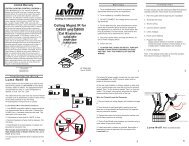
Observed Problem Possible Cause What to Do<br />
<strong>Switch</strong> timer does not switch ON/OFF but<br />
display looks normal.<br />
<strong>Switch</strong> timer won’t enter AUTO or<br />
RANDom mode when you press MODE.<br />
<strong>Switch</strong> timer switches at incorrect times<br />
or skips some of the programmed times.<br />
The lights or controlled devices don’t<br />
match the programmed ON/OFF status<br />
immediately after setting the time or<br />
programming a schedule.<br />
Load only operates when the remote<br />
(3-way) switch is in one position, or the<br />
switch timer ignores the remote switch.<br />
The switch timer ignores a 3-way remote<br />
switch even though it is wired correctly.<br />
The load turns off immediately after being<br />
turned on.<br />
The battery tray is difficult to replace.<br />
The switch timer operation is sluggish or<br />
not switching ON/OFF at all.<br />
<strong>Timer</strong> shows ON but the light or other<br />
controlled device is OFF.<br />
<strong>Switch</strong> timer is not set in AUTO, RANDom, or<br />
MANual mode.<br />
The time of day or timer settings have not<br />
been set.<br />
Programmed schedule(s) are incorrect.<br />
<strong>Switch</strong> timer is in RANDom mode, which varies<br />
switching times up to ±20 minutes (to give<br />
your home a “lived-in” look).<br />
The Astronomic and Specific switching times<br />
are in conflict. For example, you’ve set ON to<br />
DUSK and OFF at 8 pm, and due to seasonal<br />
changes, DUSK has advanced to 8:30 pm.<br />
NOTE: Your switch timer automatically skips<br />
any conflicting ON event as summer approaches<br />
to prevent unwanted operation of<br />
lights or other controlled devices. See “What<br />
to Do” if you want to identify and remove<br />
conflicting settings.<br />
<strong>Switch</strong> timer does not “catch up” automatically<br />
to the programmed load state. The status<br />
of the switch timer will remain as is until it<br />
comes to the next programmed ON/OFF time.<br />
The remote switch is wired incorrectly.<br />
There is an excessive length of wire (more<br />
than 100 feet), or there is buried wire to the<br />
switch.<br />
The remote switch is not functioning properly<br />
or worn out.<br />
•<br />
•<br />
•<br />
•<br />
•<br />
•<br />
•<br />
Troubleshooting Guide<br />
The remote switch or switch timer is wired<br />
wrong.<br />
There is an excessive length of wire<br />
(greater than 100 feet)<br />
There is buried wire to the remote switch.<br />
The switch timer is not functioning properly.<br />
Battery is not seated in the tray.<br />
The tray is misaligned.<br />
The contact tabs of the tray are bent.<br />
Though the “BATT” message is not being<br />
displayed, the battery is getting weak.<br />
The light or controlled device itself may be<br />
switched OFF.<br />
LIMITED ONE-YEAR WARRANTY<br />
Press MODE to select the operational mode you<br />
want to use.<br />
Make sure the time of day and at least one scheduled<br />
activity have been set.<br />
Press ON/OFF to review the settings and revise<br />
them as necessary. See instructions at the left.<br />
If you don’t want to keep the switch timer in<br />
RANDom mode, press MODE to change to AUTO<br />
mode.<br />
1.<br />
2.<br />
3.<br />
4.<br />
Complete the steps for setting the Time and<br />
Date, then temporarily change the date to<br />
June 21st.<br />
Review the DAWN and DUSK settings by<br />
pushing the ON/OFF button.<br />
Make sure the specific ON or OFF time settings<br />
won’t interfere with these DAWN and<br />
DUSK times. Make changes as necessary.<br />
When finished, change the Date setting back<br />
to today’s date.<br />
After entering your schedules or the time, then<br />
returning to the AUTO mode, push the ON/OFF button<br />
to change the load state if necessary.<br />
Recheck the wiring, especially for the jumper,<br />
according to “If a 3-way <strong>Switch</strong> <strong>Timer</strong>” and “If a<br />
Multiple <strong>Switch</strong> <strong>Timer</strong> Setup.”<br />
Eliminate the condition: either replace the buried<br />
cable, do without the remote switch, or contact<br />
Intermatic Customer Service for more options.<br />
Replace the remote switch.<br />
If the problem persists with the switch timer’s red<br />
wire disconnected or with a remote switch temporarily<br />
connected right at the switch timer, replace<br />
the non-functioning switch timer. Otherwise, try<br />
the above suggestions.<br />
Seat the battery in the tray, then reinstall.<br />
Replace the battery. To test the battery, press the<br />
ON/OFF button. The timer should “click.”<br />
Make sure the light or controlled device is<br />
switched ON and plugged in.<br />
If within one (1) year from the date of purchase, this product fails due to a defect in material or workmanship, Intermatic Incorporated will repair or replace it, at its sole option, free of charge. This warranty is<br />
extended to the original household purchaser only and is not transferable. This warranty does not apply to: (a) damage to units caused by accident, dropping or abuse in handling, acts of God or any negligent use;<br />
(b) units which have been subject to unauthorized repair, opened, taken apart or otherwise modified; (c) units not used in accordance with instructions; (d) damages exceeding the cost of the product; (e) sealed<br />
lamps and/or lamp bulbs, LED’s and batteries; (f) the finish on any portion of the product, such as surface and/or weathering, as this is considered normal wear and tear; (g) transit damage, initial installation costs,<br />
removal costs, or reinstallation costs.<br />
INTERMATIC INCORPORATED WILL NOT BE LIABLE FOR INCIDENTAL OR CONSEQUENTIAL DAMAGES. SOME STATES DO NOT ALLOW THE EXCLUSION OR LIMITATION OF INCIDENTAL OR CONSEQUENTIAL<br />
DAMAGES, SO THE ABOVE LIMITATION OR EXCLUSION MAY NOT APPLY TO YOU. THIS WARRANTY IS IN LIEU OF ALL OTHER EXPRESS OR IMPLIED WARRANTIES. ALL IMPLIED WARRANTIES, INCLUDING THE<br />
WARRANTY OF MERCHANTABILITY AND THE WARRANTY OF FITNESS FOR A PARTICULAR PURPOSE, ARE HEREBY MODIFIED TO EXIST ONLY AS CONTAINED IN THIS LIMITED WARRANTY, AND SHALL BE OF<br />
THE SAME DURATION AS THE WARRANTY PERIOD STATED ABOVE. SOME STATES DO NOT ALLOW LIMITATIONS ON THE DURATION OF AN IMPLIED WARRANTY, SO THE ABOVE LIMITATION MAY NOT APPLY TO<br />
YOU.<br />
This warranty service is available by either (a) returning the product to the dealer from whom the unit was purchased, or (b) mailing the product, along with proof of purchase, postage prepaid to the authorized<br />
service center listed below. This warranty is made by: Intermatic Incorporated/After Sales Service/7777 Winn Rd., Spring Grove, Illinois 60081-9698/815-675-7000 http://www.intermatic.com Please be sure to wrap<br />
the product securely to avoid shipping damage.<br />
INTERMATIC INCORPORATED<br />
SPRING GROVE, ILLINOIS 60081-9698<br />
158ST13133<br />
•<br />
•<br />
•<br />
•<br />
•<br />
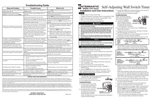
MODEL ST01 Series<br />
Installation and User Instructions<br />
Ratings<br />
Resistive (heater) 15 Amp, 120-277 VAC<br />
Tungsten (incandescent) 15 Amp @ 120 VAC, 6 Amp @ 208-277 VAC<br />
Ballast (fluorescent) 8 Amp @ 120 VAC, 4 Amp @ 208-277 VAC<br />
Motors 1 H.P. @ 120 VAC, 2 H.P. @ 240 VAC<br />
DC Loads 4 Amp @ 12 VDC, 2 Amp @ 28 VDC<br />
• Electrical shock hazard. Risk of injury or death. Remove electrical power<br />
at service panel before installing.<br />
• Risk of fire or burns from used battery. Do not recharge, disassemble, heat<br />
above 100˚ C, crush, or incinerate the lithium battery. Keep battery out of<br />
reach of children. Replace only with Panasonic type CR2 or equivalent<br />
CR2 battery approved by Underwriters Laboratories (UL). Use of a different<br />
battery type may present a risk of fire or explosion upon disposal of<br />
battery.<br />
• Risk of fire. Do not use timer to control devices that could have dangerous<br />
consequences due to inaccurate timing, such as sun lamps, sauna,<br />
heaters, crock pots, etc.<br />
•<br />
•<br />
•<br />
1 – Before Installing <strong>Switch</strong> <strong>Timer</strong>, Install and Check Battery<br />
Before installing the switch timer into the wall, make sure the<br />
supplied battery is installed and working.<br />
1.<br />
2.<br />
3.<br />
4.<br />
5.<br />
6.<br />
7.<br />
WARNING<br />
NOTICE<br />
Follow local electrical codes during installation.<br />
Risk of timer damage due to leakage if weak battery is not replaced promptly.<br />
Dispose of used battery promptly per local regulations.<br />
Open the access door to reveal the battery tray, located below<br />
the ON/OFF keypad.<br />
If there is a pull tab at the battery tray, remove the tab to connect<br />
the installed battery. Make sure battery tray is pushed<br />
fully into place. Proceed to Step 6.<br />
If the battery was supplied loose, use a flat screwdriver to pry<br />
loose the battery tray.<br />
Place the supplied “CR2” battery into the tray, observing +<br />
and – markings on tray.<br />
Replace the battery tray into the switch timer.<br />
The display will initialize itself then flash “12:00 AM” in<br />
MANual mode.<br />
Press the ON/OFF button. The switch timer should “click.”<br />
NOTE: If display doesn’t flash “12:00 am”, the battery may be<br />
dead. Replace the battery before installing the switch timer.<br />
2 – Install the <strong>Switch</strong> <strong>Timer</strong><br />
1. Turn off power at the service panel by REMOVING FUSE or<br />
TURNING THE CIRCUIT BREAKER OFF.<br />
7/16”<br />
2. Remove the existing wall switch.<br />
3. Trim building wires to 7/16” as shown.<br />
If a Single <strong>Switch</strong> Setup:<br />
BLACK WIRE<br />
a. Connect one of the two wires<br />
from the wall to the black wire<br />
from the switch timer, using<br />
the twist connectors provided.<br />
BLUE WIRE<br />
b. Connect the other wire from<br />
the wall to the blue wire from<br />
the switch timer, using the<br />
RED WIRE<br />
(capped, not connected)<br />
twist connectors provided.<br />
NOTE: The RED wire is not used in single-switch installations.<br />
Cap with a twist connector.<br />
<strong>Self</strong>-<strong>Adjusting</strong> <strong>Wall</strong> <strong>Switch</strong> <strong>Timer</strong><br />
c. Connect the GREEN wire to the grounding screw in the box. If<br />
a plastic box, connect to ground as supplied.<br />
d. Make sure all twist connectors are tight.<br />
If a 3-Way <strong>Switch</strong> Setup:<br />
NOTE: The distance between<br />
switch timer and remote switch<br />
must not exceed 100 feet.<br />
a.<br />
b.<br />
c.<br />
d.<br />
e.<br />
f.<br />
g.<br />
h.<br />
i.<br />
j.<br />
Locate the COMMON<br />
wire connected to first old<br />
switch. It might be attached<br />
to a different colored screw,<br />
or find markings on old switch.<br />
Connect BLACK wire from switch timer to COMMON wire,<br />
using a twist connector.<br />
Connect the other two wires from the old switch to the Blue<br />
and RED wires from the switch timer.<br />
Connect the GREEN wire to the grounding screw in the box. If<br />
a plastic box, connect to ground as supplied.<br />
Using diagram #1 below. Identify and remove wire “C” from<br />
the “Common” terminal of your existing remote switch.<br />
DIAGRAM 1:<br />
TYPICAL<br />
EXISTING<br />
2-SWITCH<br />
SETUP<br />
Using diagram # 2 below, remove and reconnect wires “B”<br />
and “C” to the “Common” terminal of your remote switch,<br />
using the supplied piece of jumper wire, if necessary. Follow<br />
diagram # 3 below, if using a new single-pole remote switch.<br />
NOTE: For new construction or to replace a dimmer switch,<br />
a lighted switch, or a 3-way switch without screw terminals,<br />
a single-pole switch can be used at the remote location, as<br />
shown.<br />
NOTE: If the building’s wiring colors don’t allow you to tell<br />
wire “A” from “B,” just pick one of the two wires and connect<br />
as if it is wire “B.” After the installation is complete, if the controlled<br />
light or device will not turn on properly, simply reverse<br />
wires “A” and “B.” See Steps J and K for how to check.<br />
Tuck wires into the timer wall box leaving room for the timer.<br />
Using screws provided, mount the switch timer into the wall<br />
box, then install the wall plate.<br />
Install the remote 3-way switch in its box and install wall<br />
plate. Turn the power back on at the service panel.<br />
Make sure the switch timer displays “MAN” mode. Do the following<br />
test with the remote switch in each of its 2 positions:<br />
Press the ON/OFF button on the switch timer several times.<br />
Each time that you push the ON/OFF button, the switch timer<br />
should “click” and the controlled light or device (the “load”)<br />
should turn on or off. If so, proceed to Step K.<br />
-<br />
LINE<br />
DIAGRAM 2:<br />
LINE<br />
2-SWITCH SETUP,<br />
TIMER INSTALL<br />
RE-USING EXISTING<br />
REMOTE 3-WAY SWITCH<br />
DIAGRAM 3:<br />
2-SWITCH SETUP,<br />
TIMER INSTALL USING<br />
NEW SINGLE-POLE<br />
REMOTE SWITCH<br />
3-WAY<br />
MAIN SWITCH<br />
LINE<br />
BLACK<br />
“COMMON” TERMINAL<br />
BLACK<br />
WIRE “A”<br />
WIRE “B”<br />
TIMER<br />
BLUE<br />
RED<br />
NOT USED<br />
TIMER<br />
WIRE FROM<br />
“COMMON” OF<br />
OLD SWITCH<br />
BLACK WIRE<br />
WIRE “C”<br />
3-WAY<br />
REMOTE SWITCH<br />
BLUE<br />
RED<br />
WIRE “A”<br />
WIRE “B”<br />
3-WAY<br />
REMOTE SWITCH<br />
WIRE “A”<br />
WIRE “B”<br />
RED WIRE<br />
BLUE WIRE<br />
If the timer clicks but the load does not operate, re-check<br />
your wiring and make sure the load is functional.<br />
LOAD<br />
NEUTRAL<br />
WIRE “C”<br />
JUMPER<br />
SINGLE-POLE<br />
REMOTE SWITCH<br />
LOAD<br />
“COMMON” TERMINAL<br />
WIRE “C”<br />
JUMPER<br />
NEUTRAL<br />
LOAD<br />
NEUTRAL
3 – Intro to Programming: Read Before You Begin<br />
• As you use the menus to program, it will be helpful to have an<br />
overview of how they are organized. Press the MODE button to<br />
rotate through the switch timer’s modes: SET UP, PROGRAM,<br />
AUTO, RANDOM, and MANUAL. All menus “loop”, so they<br />
repeat when you get to the end. AUTO and RANDOM modes<br />
are skipped until there is at least one ON/OFF setting.<br />
• Once you reach a Mode you want to work with, press the ON/<br />
OFF button to rotate through the loop of settings available for<br />
that Mode, returning to the beginning. For example, in SET UP<br />
mode, you will see HOUR, MINute, AM/PM, Year, MONth, etc.<br />
• Use the + or – buttons to change a setting when it is FLASH-<br />
ING (e.g., the correct hour). Holding the button makes the<br />
numbers scroll faster. Pressing ON/OFF again advances to the<br />
next setting and automatically saves — whether you changed<br />
the setting or not. Saving is automatic, there’s no extra step.<br />
• If you’re interrupted during programming, your work to that<br />
point is automatically saved after 5 minutes.<br />
• Press MODE when you’re finished to navigate to the mode you<br />
want to operate the switch timer: Auto, Manual, or Random.<br />
4 – Clear Any Existing Programming<br />
It’s unlikely that the new switch timer has any existing programming<br />
but to make sure, use this procedure before setting the time.<br />
1.<br />
2.<br />
3.<br />
4.<br />
-<br />
If the timer clicks but the load only operates when the remote<br />
switch is in one of its 2 positions, you need to turn off<br />
the power at the service panel, then reverse wires “A” and<br />
“B.” You can reverse wires “A” and “B” at the remote switch<br />
wall box, or you can reverse wires “A” and “B” where they<br />
connect to the red and blue wires of the switch timer. Then<br />
turn power back on at the service panel and repeat Step J.<br />
k. Verify that the controlled load turns on or off each time that the<br />
remote switch is operated. Your timer is now ready to be set.<br />
If a Multiple <strong>Switch</strong> <strong>Timer</strong> Setup:<br />
Multi-switch applications using the ST01 Series switch timer are<br />
wired differently than when using conventional toggle switches.<br />
Read the following installation instructions carefully.<br />
• Multiple switch timers may be mounted in an unlimited number<br />
of adjacent junction box slots.<br />
• No derating is required for multiple switch timers.<br />
For a three-switch setup:<br />
BLACK<br />
LINE<br />
TIMER<br />
ADDITIONAL WIRE<br />
BLUE<br />
RED<br />
For four or more switch setups:<br />
Use the preceding 3-switch installation diagram and wire 4-way<br />
switches between the two 3-way switches.<br />
NOTE: The remote switch(es) may not function reliably when the<br />
accumulated wire length to the remote switch(es) exceeds 100<br />
feet or if the wiring to the remote switch(es) is buried underground.<br />
Contact Intermatic Customer Service for details.<br />
NOTE: Used remote switches from a previous conventional<br />
installation may not function reliably with an electronic timer. Try<br />
a brand new remote switch if function is intermittent.<br />
You are now ready to set the DATE and TIME.<br />
Open the front cover.<br />
Hold down ON/OFF.<br />
Using a pen or paper clip, press and release RESET, which is<br />
the small round button to the lower right of the + button.<br />
When the screen displays INIT, release ON/OFF. The screen will<br />
initialize, then flash “12:00 am” in MANual mode.<br />
All previous settings are now deleted.<br />
LOAD<br />
TWO 3-WAY SWITCHES<br />
NEUTRAL<br />
5 – Set the Date and Time<br />
In order for the Astronomic Feature and automatic Daylight Saving<br />
Time settings to function properly, the CALENDAR settings<br />
must be entered correctly.<br />
WHAT IT MEANS: The icon of the LIGHT BULB indicates whether<br />
the switch timer is ON or OFF. The WHITE area of the example<br />
screens is what will be flashing on your switch timer.<br />
1.<br />
2.<br />
3.<br />
4.<br />
5.<br />
6.<br />
6 – Set Initial Pair of ON and OFF Times<br />
You have many options with up to 40 timer settings:<br />
• Set to a specific ON/OFF time.<br />
• Set to DAWN and DUSK, which automatically adjust as the<br />
seasons change. This is the ASTRONOMIC feature.<br />
• Set to activate ALL days, M-F, WeeKenD, or individual days.<br />
Programs are created in two procedures: setting an ON time followed<br />
by setting an OFF time. You must set each time separately.<br />
The instructions below will guide you as follows:<br />
• First, for setting an ON time, which can be DAWN or DUSK,<br />
or a specific time such as 6:00 pm,<br />
• Then for setting an OFF time which can also be DAWN or<br />
Dusk, or a specific time.<br />
1.<br />
Press MODE until the screen displays SET UP.<br />
The first time, the hours/minutes display will<br />
be flashing (Fig. 4).<br />
Press ON/OFF to display HOUR (Fig. 5), then<br />
press + until the correct hour and AM/PM are<br />
shown.<br />
NOTE: If you go too far, press the - button to<br />
back up, or press + until you loop back.<br />
Press ON/OFF to display MIN ( Fig. 6), then<br />
press + until the correct minute is shown.<br />
Repeat this routine for YEAR, MONTH, DATE.<br />
Verify that the day of the week is correct<br />
(Fig. 7). If wrong, press + or – to loop back,<br />
then reset the calendar information.<br />
Press ON/OFF to display DST (Fig. 8), and set<br />
whether you want to adjust automatically for<br />
Daylight Saving Time (DST).<br />
-<br />
If you use DST, press + for AUTO.<br />
- If you do not use DST, press + for MANual.<br />
7. Press ON/OFF to set your<br />
ZONE (Fig. 9). This feature<br />
tracks changes in sunrise<br />
North<br />
North<br />
and sunset times. Press +<br />
Center<br />
Center<br />
to select your local zone:<br />
NoRTH, CENTer, or SOUth South<br />
(Fig. 10).<br />
South<br />
8. You can set DAWN or<br />
Fig. 10 Fig. 8<br />
DUSK to your exact time<br />
in your area according to your newspaper or online. Use the<br />
following procedures to do so, or press ON/OFF 3 times to skip.<br />
a. Press ON/OFF to set your exact local time<br />
for DAWN (Fig 11), then press + to set the<br />
correct HOUR.<br />
b. Press ON/OFF to display MIN (Fig. 12), then<br />
press + until the correct minute is shown.<br />
c. Repeat Steps a and b to set exact local time<br />
for DUSK.<br />
9. Press ON/OFF again and you’ll loop back to SET UP.<br />
CHECK YOUR SETTINGS: Press ON/OFF repeatedly to loop back<br />
around to review your date and time settings. If anything is<br />
wrong, make corrections using the above steps.<br />
Press MODE until the screen displays ProGraM<br />
below the time of day (Fig. 13).<br />
2. Press ON/OFF to display the program number,<br />
then press + until you see the program number<br />
you want to set (Fig. 14).<br />
3. Press ON/OFF, then press + if necessary, to<br />
display ON for setting the ON time (Fig. 15).<br />
Continue to press + for OFF (if setting an OFF<br />
time) or SKIP (if deleting a setting).<br />
4. Press ON/OFF, then press + to display whether you want ON<br />
to be set for DUSK, DAWN, or a specific time which would be<br />
shown as “12:00” (until you change it).<br />
If ON is to be at Dawn or Dusk:<br />
NOTE: Some people like to set DUSK as an ON time and match it<br />
with a specific time such as 11:00 pm for OFF.<br />
a. Press + to display DUSK (Fig. 16). Continue to<br />
press + for DAWN (if setting DAWN as the on<br />
time).<br />
b. Press ON/OFF to display the days you want<br />
the setting to be active, then press + to select<br />
either ALL days, M-F, WeeKenD, or an individual<br />
day. Fig. 17 shows ALL as an example.<br />
c. Press ON/OFF again. The display will briefly show SAVE.<br />
You have successfully set the ON time as DUSK, and must now<br />
repeat this procedure to set the OFF time to go with it.<br />
The display will loop back to Step 2 above, ready<br />
for you to set another program. Press + to display<br />
a flashing “02” (Fig. 18).<br />
• To set PROGRAM 2, follow this procedure<br />
again, beginning at Step 2 above.<br />
• When you’re finished, press MODE to exit from programming<br />
and automatically save your new settings.<br />
If ON is to be at a Specific Time such as 8:15 pm:<br />
a. Press + to display “12:00” (Fig. 19).<br />
b. Press ON/OFF to display the hour (Fig. 20), then<br />
press + until the correct hour is shown.<br />
NOTE: If you go too far, press the – to back<br />
up, or press + until you loop back around.<br />
c. Press ON/OFF to display the minutes (Fig. 21),<br />
then press + until the correct minute is shown.<br />
d. Press ON/OFF to display the days you want<br />
the setting to be active, then press + to select<br />
either a specific day of the week, ALL days, M-<br />
F (work week only), or WKD (weekend only).<br />
Fig. 22 shows ALL as an example.<br />
e. Press ON/OFF again The display will briefly show SAVE.<br />
You have successfully set the ON time to 8:15 pm, and must now<br />
repeat this procedure to set the OFF time to go with it.<br />
The display will loop back to Step 2 above, ready<br />
for you to set another program. Press + to display<br />
a flashing “02” (Fig. 23).<br />
• To set PROGRAM 2, follow the procedure beginning<br />
at Step 2 on the other side of this sheet. Repeat these<br />
steps to create up to 40 unique ON/OFF settings.<br />
• When you’re finished, press MODE to exit from programming<br />
and automatically save your new settings.<br />
Once set up, you have three choices for using the switch timer.<br />
To make a selection, open the front cover and press the MODE<br />
button until you see your choice of the following options:<br />
•<br />
•<br />
About the Battery<br />
•<br />
•<br />
•<br />
The single lithium CR2 battery operates the ON/OFF function<br />
(“click-click”) and maintains time of day and date. The screen<br />
flashes “BATT” when the battery is getting low.<br />
The battery may be changed without removing AC power.<br />
You have about one minute to swap batteries before the<br />
switch timer “forgets” the date and time settings. Afterwards,<br />
if the display is wrong or flashes “12:00 AM”, reset the time<br />
and date. All other settings (your ON/OFF programming)<br />
remain in memory indefinitely without battery or AC power.<br />
To test the battery, press the ON/OFF button. The timer should<br />
“click.”<br />
Replace the battery per Section 1 Instructions as soon as possible<br />
after the low “BATT” message appears.<br />
Do not leave exhausted battery in <strong>Switch</strong> <strong>Timer</strong>. (Risk of leakage.)<br />
Replace only with Panasonic Type CR2 lithium battery or equivalent<br />
CR2 battery approved by Underwriters Laboratories (UL).<br />
Dispose of the used battery promptly according to local regulations.<br />
Keep battery away from children. Do not disassemble<br />
and do not dispose of battery in fire.<br />
•<br />
•<br />
•<br />
•<br />
7 – Selecting AUTO, RANDom, or MANual Operation<br />
AUTO — uses the timer settings you have programmed.<br />
RANDom — gives your home a “lived-in” look by varying<br />
your settings by a random amount of ± 20 minutes or so.<br />
MANual — makes the switch into a standard ON/OFF switch<br />
without timer settings. Press on the door of the switch timer<br />
for ON, press again for OFF.<br />
•<br />
•<br />
Changing Program Times<br />
Deleting an ON or OFF Setting<br />
Use these steps to delete an existing ON or OFF setting that you<br />
no longer want (for example, special settings from a vacation.)<br />
1. Press MODE until the screen displays ProGraM<br />
below the time of day (Fig. 24).<br />
2. Press ON/OFF to display the program number,<br />
then press the + button until you see the program<br />
number you want to delete (Fig. 25).<br />
3. Press ON/OFF, then the + button until SKIP is<br />
displayed (Fig. 26). The switch timer will now<br />
suppress this setting.<br />
4. Press ON/OFF again to cycle through the program<br />
until the display briefly shows SAVE.<br />
5. Press MODE to exit from programming and automatically save<br />
your new settings.<br />
NOTE: Repeat this step and select ON or OFF to reactivate the setting.<br />
Revising an ON or OFF Setting<br />
Use these steps to revise an existing ON or OFF setting.<br />
1. Press MODE until the screen displays ProGraM<br />
below the time of day (Fig. 27).<br />
2. Press ON/OFF to display the program number,<br />
then press the + button until you see the program<br />
number you want to revise (Fig. 28).<br />
3. Press the ON/OFF button as many times as<br />
necessary to display the setting you want to<br />
revise, for example, the MINUTE (Fig. 29).<br />
4. Now press the + button again to display the<br />
new minute you want to set (Fig. 30).<br />
5. Press MODE to exit from programming and<br />
automatically save your new settings.