

SJ700-2 Instruction Manual NT204DX - Hitachi America, Ltd.
SJ700-2 Instruction Manual NT204DX - Hitachi America, Ltd.
SJ700-2 Instruction Manual NT204DX - Hitachi America, Ltd.

You also want an ePaper? Increase the reach of your titles
YUMPU automatically turns print PDFs into web optimized ePapers that Google loves.
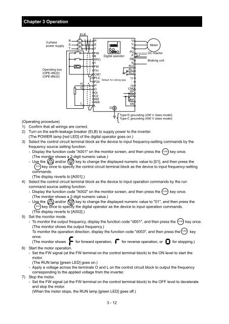
Chapter 3 Operation<br />
ELB<br />
3-phase<br />
power supply<br />
Operating box<br />
(OPE-4MJ2)<br />
(OPE-8MJ2)<br />
R<br />
S<br />
T<br />
H<br />
O<br />
L<br />
R<br />
U<br />
S<br />
V<br />
T<br />
W<br />
FW<br />
PD<br />
8 Digital operator P<br />
(RV)<br />
RB<br />
1<br />
N<br />
FM<br />
AL0<br />
TH<br />
AL1<br />
CM1<br />
AL2<br />
PLC<br />
11<br />
Default: for sinking type<br />
P24<br />
・・・・<br />
H<br />
15<br />
O<br />
CM2<br />
OI<br />
SP<br />
O2<br />
SN<br />
AM<br />
RP<br />
AMI<br />
SN<br />
L<br />
G<br />
Motor<br />
DC reactor<br />
Braking unit<br />
Type-D grounding (200 V class model)<br />
Type-C grounding (400 V class model)<br />
(Operating procedure)<br />
1) Confirm that all wirings are correct.<br />
2) Turn on the earth-leakage breaker (ELB) to supply power to the inverter.<br />
(The POWER lamp [red LED] of the digital operator goes on.)<br />
3) Select the control circuit terminal block as the device to input frequency-setting commands by the<br />
frequency source setting function.<br />
- Display the function code "A001" on the monitor screen, and then press the<br />
FUNC<br />
key once.<br />
(The monitor shows a 2-digit numeric value.)<br />
- Use the 1 and/or 2 key to change the displayed numeric value to [01], and then press the<br />
STR<br />
key once to specify the control circuit terminal block as the device to input frequency-setting<br />
commands.<br />
(The display reverts to [A001].)<br />
4) Select the control circuit terminal block as the device to input operation commands by the run<br />
command source setting function.<br />
FUNC<br />
- Display the function code "A002" on the monitor screen, and then press the key once.<br />
(The monitor shows a 2-digit numeric value.)<br />
- Use the 1 and/or 2 key to change the displayed numeric value to "01", and then press the<br />
STR<br />
key once to specify the digital operator as the device to input operation commands.<br />
(The display reverts to [A002].)<br />
5) Set the monitor mode.<br />
FUNC<br />
- To monitor the output frequency, display the function code "d001", and then press the key once.<br />
(The monitor shows the output frequency.)<br />
FUNC<br />
To monitor the operation direction, display the function code "d003", and then press the key<br />
once.<br />
(The monitor shows for forward operation, for reverse operation, or for stopping.)<br />
6) Start the motor operation.<br />
- Set the FW signal (at the FW terminal on the control terminal block) to the ON level to start the<br />
motor.<br />
(The RUN lamp [green LED] goes on.)<br />
- Apply a voltage across the terminals O and L on the control circuit block to output the frequency<br />
corresponding to the applied voltage from the inverter.<br />
7) Stop the motor.<br />
- Set the FW signal (at the FW terminal on the control terminal block) to the OFF level to decelerate<br />
and stop the motor.<br />
(When the motor stops, the RUN lamp [green LED] goes off.)<br />
3 - 12


