SJ700-2 Instruction Manual NT204DX - Hitachi America, Ltd.
SJ700-2 Instruction Manual NT204DX - Hitachi America, Ltd. SJ700-2 Instruction Manual NT204DX - Hitachi America, Ltd.
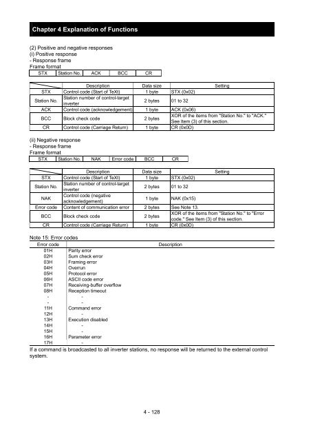
Chapter 4 Explanation of Functions (2) Positive and negative responses (i) Positive response - Response frame Frame format STX Station No. ACK BCC CR Description Data size Setting STX Control code (Start of TeXt) 1 byte STX (0x02) Station No. Station number of control-target inverter 2 bytes 01 to 32 ACK Control code (acknowledgement) 1 byte ACK (0x06) BCC Block check code 2 bytes XOR of the items from "Station No." to "ACK." See Item (3) of this section. CR Control code (Carriage Return) 1 byte CR (0x0D) (ii) Negative response - Response frame Frame format STX Station No. NAK Error code BCC CR Description Data size Setting STX Control code (Start of TeXt) 1 byte STX (0x02) Station No. Station number of control-target inverter 2 bytes 01 to 32 NAK Control code (negative acknowledgement) 1 byte NAK (0x15) Error code Content of communication error 2 bytes See Note 13. BCC Block check code 2 bytes XOR of the items from "Station No." to "Error code." See Item (3) of this section. CR Control code (Carriage Return) 1 byte CR (0x0D) Note 15: Error codes Error code Description 01H Parity error 02H Sum check error 03H Framing error 04H Overrun 05H Protocol error 06H ASCII code error 07H Receiving-buffer overflow 08H Reception timeout - - - - 11H Command error 12H - 13H Execution disabled 14H - 15H - 16H Parameter error 17H - If a command is broadcasted to all inverter stations, no response will be returned to the external control system. 4 - 128
Chapter 4 Explanation of Functions (3) How to calculate the block check code (BCC) (Example) When using the 01 command (frequency-setting command) to set the inverter output frequency to 5 Hz (the station No. of the inverter is 01): Transmission frame configuration Station No. Command Data ASCII code The contents of "Station No." to "Data" are converted into ASCII data, and the ASCII data is XORed bit by bit. The final XOR result is set as the block check code (BCC). In the above example of transmission frame, BCC is calculated as follows: (Reference) ASCII code conversion table Character data ASCII code Character data ASCII code STX 2 A 41 ACK 6 B 42 CR 0D C 43 NAK 15 D 44 0 30 E 45 1 31 F 46 2 32 H 48 3 33 P 50 4 34 b 62 5 35 6 36 7 37 8 38 9 39 05 (This result is used as BCC.) 4 - 129
- Page 141 and 142: Chapter 4 Explanation of Functions
- Page 143 and 144: Chapter 4 Explanation of Functions
- Page 145 and 146: Chapter 4 Explanation of Functions
- Page 147 and 148: Chapter 4 Explanation of Functions
- Page 149 and 150: Voltage across main circuit termina
- Page 151 and 152: Chapter 4 Explanation of Functions
- Page 153 and 154: Chapter 4 Explanation of Functions
- Page 155 and 156: Chapter 4 Explanation of Functions
- Page 157 and 158: Chapter 4 Explanation of Functions
- Page 159 and 160: Chapter 4 Explanation of Functions
- Page 161 and 162: Chapter 4 Explanation of Functions
- Page 163 and 164: Chapter 4 Explanation of Functions
- Page 165 and 166: Chapter 4 Explanation of Functions
- Page 167 and 168: Chapter 4 Explanation of Functions
- Page 169 and 170: Chapter 4 Explanation of Functions
- Page 171 and 172: Chapter 4 Explanation of Functions
- Page 173 and 174: Chapter 4 Explanation of Functions
- Page 175 and 176: Chapter 4 Explanation of Functions
- Page 177 and 178: Chapter 4 Explanation of Functions
- Page 179 and 180: Chapter 4 Explanation of Functions
- Page 181 and 182: Chapter 4 Explanation of Functions
- Page 183 and 184: Chapter 4 Explanation of Functions
- Page 185 and 186: Chapter 4 Explanation of Functions
- Page 187 and 188: Chapter 4 Explanation of Functions
- Page 189 and 190: Chapter 4 Explanation of Functions
- Page 191: Chapter 4 Explanation of Functions
- Page 195 and 196: Chapter 4 Explanation of Functions
- Page 197 and 198: Chapter 4 Explanation of Functions
- Page 199 and 200: Chapter 4 Explanation of Functions
- Page 201 and 202: Chapter 4 Explanation of Functions
- Page 203 and 204: Chapter 4 Explanation of Functions
- Page 205 and 206: Chapter 4 Explanation of Functions
- Page 207 and 208: Chapter 4 Explanation of Functions
- Page 209 and 210: Chapter 4 Explanation of Functions
- Page 211 and 212: Chapter 4 Explanation of Functions
- Page 213 and 214: Chapter 4 Explanation of Functions
- Page 215 and 216: Chapter 4 Explanation of Functions
- Page 217 and 218: Chapter 4 Explanation of Functions
- Page 219 and 220: Chapter 4 Explanation of Functions
- Page 221 and 222: Chapter 4 Explanation of Functions
- Page 223 and 224: Chapter 4 Explanation of Functions
- Page 225 and 226: Chapter 4 Explanation of Functions
- Page 227 and 228: Chapter 4 Explanation of Functions
- Page 230 and 231: Chapter 5 Error Codes 5.1 Error Cod
- Page 232 and 233: Chapter 5 Error Codes Name Gate arr
- Page 234 and 235: Chapter 5 Error Codes 5.1.2 Option
- Page 236 and 237: Chapter 5 Error Codes 3) Error indi
- Page 238 and 239: Chapter 5 Error Codes 5.1.3 Trip co
- Page 240: Chapter 6 Maintenance and Inspectio
Chapter 4 Explanation of Functions<br />
(2) Positive and negative responses<br />
(i) Positive response<br />
- Response frame<br />
Frame format<br />
STX Station No. ACK BCC CR<br />
Description Data size Setting<br />
STX Control code (Start of TeXt) 1 byte STX (0x02)<br />
Station No.<br />
Station number of control-target<br />
inverter<br />
2 bytes 01 to 32<br />
ACK Control code (acknowledgement) 1 byte ACK (0x06)<br />
BCC Block check code 2 bytes<br />
XOR of the items from "Station No." to "ACK."<br />
See Item (3) of this section.<br />
CR Control code (Carriage Return) 1 byte CR (0x0D)<br />
(ii) Negative response<br />
- Response frame<br />
Frame format<br />
STX Station No. NAK Error code BCC CR<br />
Description Data size Setting<br />
STX Control code (Start of TeXt) 1 byte STX (0x02)<br />
Station No.<br />
Station number of control-target<br />
inverter<br />
2 bytes 01 to 32<br />
NAK<br />
Control code (negative<br />
acknowledgement)<br />
1 byte NAK (0x15)<br />
Error code Content of communication error 2 bytes See Note 13.<br />
BCC Block check code 2 bytes<br />
XOR of the items from "Station No." to "Error<br />
code." See Item (3) of this section.<br />
CR Control code (Carriage Return) 1 byte CR (0x0D)<br />
Note 15: Error codes<br />
Error code<br />
Description<br />
01H Parity error<br />
02H Sum check error<br />
03H Framing error<br />
04H Overrun<br />
05H Protocol error<br />
06H ASCII code error<br />
07H Receiving-buffer overflow<br />
08H Reception timeout<br />
- -<br />
- -<br />
11H Command error<br />
12H -<br />
13H Execution disabled<br />
14H -<br />
15H -<br />
16H Parameter error<br />
17H -<br />
If a command is broadcasted to all inverter stations, no response will be returned to the external control<br />
system.<br />
4 - 128


