SJ700-2 Instruction Manual NT204DX - Hitachi America, Ltd.
SJ700-2 Instruction Manual NT204DX - Hitachi America, Ltd. SJ700-2 Instruction Manual NT204DX - Hitachi America, Ltd.
Chapter 4 Explanation of Functions Note 6: The table below lists the functions of the intelligent input terminals and corresponding hexadecimal data for 12 command. (For details, see the explanation of the intelligent input terminal functions.) Data (hexadecimal) Description Data (hexadecimal) Description 0000000000000001 0000000000000002 0000000000000004 0000000000000008 0000000000000010 0000000000000020 0000000000000040 0000000000000080 0000000000000100 0000000000000200 0000000000000400 0000000000000800 0000000000001000 0000000000002000 0000000000004000 0000000000008000 0000000000010000 0000000000020000 0000000000040000 0000000000080000 0000000000100000 0000000000200000 0000000000400000 0000000000800000 0000000001000000 0000000002000000 0000000004000000 0000000008000000 0000000010000000 0000000020000000 0000000040000000 0000000080000000 - AHD: analog command holding CP1: multistage position settings selection 1 CP2: multistage position settings selection 2 CP3: multistage position settings selection 3 ORL: Zero-return limit function ORG: Zero-return trigger function FOT: forward drive stop ROT: reverse drive stop SPD: speed / position switching PCNT: pulse counter PCC: pulse counter clear - - - - - - - - - - - - - - - - - - - - 0000000100000000 0000000200000000 0000000400000000 0000000800000000 0000001000000000 0000002000000000 0000004000000000 0000008000000000 0000010000000000 0000020000000000 0000040000000000 0000080000000000 0000100000000000 0000200000000000 0000400000000000 0000800000000000 0001000000000000 0002000000000000 0004000000000000 0008000000000000 0010000000000000 0020000000000000 0040000000000000 0080000000000000 0100000000000000 0200000000000000 0400000000000000 0800000000000000 1000000000000000 2000000000000000 4000000000000000 8000000000000000 - - - - - - - - - - - - - - - - - - - - - - - - - - - - - - - - (Example) When activating the "forward rotation," "Multispeed 1 setting," and "Multispeed 2 setting" settings on the inverter with station No. 01, specify the following in the Data part: 0x0000000000000001 + 0x0000000000000004 + 0x0000000000000008 = 0x000000000000000D Consequently, the whole transmission frame is as follows: (STX) |01|02|000000000000000D| (BCC) | (CR) - Response frame Positive response: See Item (2)-(i) of this section. Negative response: See Item (2)-(ii) of this section. 4 - 120
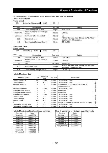
Chapter 4 Explanation of Functions (iv) 03 command: This command reads all monitored data from the inverter. - Transmission frame Frame format STX Station No. Command BCC CR Description Data size Setting STX Control code (Start of TeXt) 1 byte STX (0x02) Station No. Station number of control-target inverter 2 bytes 01 to 32 Command Command to be transmitted 2 bytes 03 BCC Block check code 2 bytes XOR of the items from "Station No." to "Data." See Item (3) of this section. CR Control code (Carriage Return) 1 byte CR (0x0D) - Response frame Frame format STX Station No. Data BCC CR Description Data size Setting STX Control code (Start of TeXt) 1 byte STX (0x02) Station No. Station number of control-target inverter 2 bytes 01 to 32 Data Data 104 bytes See Note 7. BCC Block check code 2 bytes XOR of the items from "Station No." to "Data." See Item (3) of this section. CR Control code (Carriage Return) 1 byte CR (0x0D) Note 7: Monitored data Monitoring item Unit Magnification Data size Description Output frequency Hz ×100 8 bytes Decimal ASCII code Output current A ×10 8 bytes Decimal ASCII code Rotation direction - - 8 bytes "0" stopping, "1" (forward rotation), or "2" (reverse rotation) PID feedback data % ×100 8 bytes Decimal ASCII code Intelligent input terminal - - 8 bytes See Note 7. Intelligent output terminal - - 8 bytes See Note 8. Frequency conversion - ×100 8 bytes Decimal ASCII code Output torque % ×1 8 bytes Decimal ASCII code Output voltage V ×10 8 bytes Decimal ASCII code Electric power kW ×10 8 bytes Decimal ASCII code - - - 8 bytes Always "00000000" (reserved for data storage) Cumulative running time h ×1 8 bytes Decimal ASCII code Cumulative power-on time h ×1 8 bytes Decimal ASCII code ↑ High-order bytes Low-order bytes ↓ Note 8: Monitoring of intelligent input terminals Note 8: Monitoring of intelligent output terminals Terminal Data Terminal Data Terminal 1 00000001 Terminal 11 00000001 Terminal 2 00000002 Terminal 12 00000002 Terminal 3 00000004 Terminal 13 00000004 Terminal 4 00000008 Terminal 14 00000008 Terminal 5 00000010 Terminal 15 00000010 Terminal 6 00000020 Relay terminal 00000020 Terminal 7 00000040 Terminal 8 00000080 FW terminal 00000100 4 - 121
- Page 133 and 134: Chapter 4 Explanation of Functions
- Page 135 and 136: Chapter 4 Explanation of Functions
- Page 137 and 138: Chapter 4 Explanation of Functions
- Page 139 and 140: Chapter 4 Explanation of Functions
- Page 141 and 142: Chapter 4 Explanation of Functions
- Page 143 and 144: Chapter 4 Explanation of Functions
- Page 145 and 146: Chapter 4 Explanation of Functions
- Page 147 and 148: Chapter 4 Explanation of Functions
- Page 149 and 150: Voltage across main circuit termina
- Page 151 and 152: Chapter 4 Explanation of Functions
- Page 153 and 154: Chapter 4 Explanation of Functions
- Page 155 and 156: Chapter 4 Explanation of Functions
- Page 157 and 158: Chapter 4 Explanation of Functions
- Page 159 and 160: Chapter 4 Explanation of Functions
- Page 161 and 162: Chapter 4 Explanation of Functions
- Page 163 and 164: Chapter 4 Explanation of Functions
- Page 165 and 166: Chapter 4 Explanation of Functions
- Page 167 and 168: Chapter 4 Explanation of Functions
- Page 169 and 170: Chapter 4 Explanation of Functions
- Page 171 and 172: Chapter 4 Explanation of Functions
- Page 173 and 174: Chapter 4 Explanation of Functions
- Page 175 and 176: Chapter 4 Explanation of Functions
- Page 177 and 178: Chapter 4 Explanation of Functions
- Page 179 and 180: Chapter 4 Explanation of Functions
- Page 181 and 182: Chapter 4 Explanation of Functions
- Page 183: Chapter 4 Explanation of Functions
- Page 187 and 188: Chapter 4 Explanation of Functions
- Page 189 and 190: Chapter 4 Explanation of Functions
- Page 191 and 192: Chapter 4 Explanation of Functions
- Page 193 and 194: Chapter 4 Explanation of Functions
- Page 195 and 196: Chapter 4 Explanation of Functions
- Page 197 and 198: Chapter 4 Explanation of Functions
- Page 199 and 200: Chapter 4 Explanation of Functions
- Page 201 and 202: Chapter 4 Explanation of Functions
- Page 203 and 204: Chapter 4 Explanation of Functions
- Page 205 and 206: Chapter 4 Explanation of Functions
- Page 207 and 208: Chapter 4 Explanation of Functions
- Page 209 and 210: Chapter 4 Explanation of Functions
- Page 211 and 212: Chapter 4 Explanation of Functions
- Page 213 and 214: Chapter 4 Explanation of Functions
- Page 215 and 216: Chapter 4 Explanation of Functions
- Page 217 and 218: Chapter 4 Explanation of Functions
- Page 219 and 220: Chapter 4 Explanation of Functions
- Page 221 and 222: Chapter 4 Explanation of Functions
- Page 223 and 224: Chapter 4 Explanation of Functions
- Page 225 and 226: Chapter 4 Explanation of Functions
- Page 227 and 228: Chapter 4 Explanation of Functions
- Page 230 and 231: Chapter 5 Error Codes 5.1 Error Cod
- Page 232 and 233: Chapter 5 Error Codes Name Gate arr
Chapter 4 Explanation of Functions<br />
(iv) 03 command: This command reads all monitored data from the inverter.<br />
- Transmission frame<br />
Frame format<br />
STX Station No. Command BCC CR<br />
Description Data size Setting<br />
STX Control code (Start of TeXt) 1 byte STX (0x02)<br />
Station No.<br />
Station number of control-target<br />
inverter<br />
2 bytes 01 to 32<br />
Command Command to be transmitted 2 bytes 03<br />
BCC Block check code 2 bytes<br />
XOR of the items from "Station No." to "Data."<br />
See Item (3) of this section.<br />
CR Control code (Carriage Return) 1 byte CR (0x0D)<br />
- Response frame<br />
Frame format<br />
STX Station No. Data BCC CR<br />
Description Data size Setting<br />
STX Control code (Start of TeXt) 1 byte STX (0x02)<br />
Station No.<br />
Station number of control-target<br />
inverter<br />
2 bytes 01 to 32<br />
Data Data 104 bytes See Note 7.<br />
BCC Block check code 2 bytes<br />
XOR of the items from "Station No." to "Data."<br />
See Item (3) of this section.<br />
CR Control code (Carriage Return) 1 byte CR (0x0D)<br />
Note 7: Monitored data<br />
Monitoring item Unit<br />
Magnification<br />
Data size<br />
Description<br />
Output frequency Hz ×100 8 bytes Decimal ASCII code<br />
Output current A ×10 8 bytes Decimal ASCII code<br />
Rotation direction - - 8 bytes "0" stopping, "1" (forward rotation), or "2"<br />
(reverse rotation)<br />
PID feedback data % ×100 8 bytes Decimal ASCII code<br />
Intelligent input terminal - - 8 bytes See Note 7.<br />
Intelligent output terminal - - 8 bytes See Note 8.<br />
Frequency conversion - ×100 8 bytes Decimal ASCII code<br />
Output torque % ×1 8 bytes Decimal ASCII code<br />
Output voltage V ×10 8 bytes Decimal ASCII code<br />
Electric power kW ×10 8 bytes Decimal ASCII code<br />
- - - 8 bytes Always "00000000" (reserved for data storage)<br />
Cumulative running time h ×1 8 bytes Decimal ASCII code<br />
Cumulative power-on time h ×1 8 bytes Decimal ASCII code<br />
↑ High-order bytes Low-order bytes ↓<br />
Note 8: Monitoring of intelligent input terminals Note 8: Monitoring of intelligent output terminals<br />
Terminal Data Terminal Data<br />
Terminal 1 00000001 Terminal 11 00000001<br />
Terminal 2 00000002 Terminal 12 00000002<br />
Terminal 3 00000004 Terminal 13 00000004<br />
Terminal 4 00000008 Terminal 14 00000008<br />
Terminal 5 00000010 Terminal 15 00000010<br />
Terminal 6 00000020 Relay terminal 00000020<br />
Terminal 7 00000040<br />
Terminal 8 00000080<br />
FW terminal 00000100<br />
4 - 121


