

SJ700-2 Instruction Manual NT204DX - Hitachi America, Ltd.
SJ700-2 Instruction Manual NT204DX - Hitachi America, Ltd.
SJ700-2 Instruction Manual NT204DX - Hitachi America, Ltd.

Create successful ePaper yourself
Turn your PDF publications into a flip-book with our unique Google optimized e-Paper software.
Chapter 4 Explanation of Functions<br />
Related code<br />
4.3.17 Forward/reverse drive stop function (FOT/ROT)<br />
C001-C008 intelligent input terminals<br />
- The forward/reverse drive stop function allows you to prevent motor<br />
operation from deviating from the specified control range according<br />
to signals from the control range limit switches.<br />
- When the FOT terminal is turned on, the torque for forward rotation is limited to 10%. When the ROT<br />
terminal is turned on, the torque for reverse rotation is limited to 10%. This function can be used as a limit<br />
switch function at the machine end. This function is activated by setting 71 (FOT) and 72 (ROT) on<br />
intelligent input terminals 1-8 (C001- C008<br />
4.3.18 Position range specification function<br />
Related code<br />
P072: Position range specification (forward)<br />
- The position control ranges for forward and reverse rotations can P073: Position range specification (reverse)<br />
be specified by the position range specification (forward) (P072) and<br />
position range specification (reverse) (P073), respectively. If the value of the current position counter<br />
exceeds one of these ranges, a position control range error (E63.* or E73.*) causes the inverter to trip and<br />
enter free-running status.<br />
- The values specified by P072 and P073 limit the maximum values of multistage position settings 0 to 7<br />
(P060 to P067).<br />
(Position settings cannot exceed the specified position ranges.)<br />
4.3.19 Teaching function<br />
- The teaching function allows you to make the inverter run and stop<br />
the motor arbitrarily, and then store position data as a position<br />
command in an arbitrary position command area of memory.<br />
- Assign function "45" (ORT) to an intelligent input terminal 1-8 (C001-C008).<br />
Related code<br />
C001-C008 intelligent input terminals<br />
P012: Control pulse setting<br />
P013: Home search stop position setting<br />
The ORT terminal functions as the teaching terminal when "02" (absolute position control) or "03"<br />
(high-resolution absolute position control) is specified for the control pulse setting (P012).<br />
<br />
Select the position command to be set by teaching selection (P074).<br />
Move the workpiece.<br />
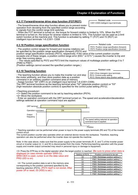
- Enter an operation command with the ORT terminal turned on. The speed and acceleration/deceleration<br />
settings selected at operation command input are applied.<br />
ORT terminal<br />
Operation command<br />
ON<br />
ON<br />
Output<br />
frequency<br />
The speed setting selected at operation<br />
command input is applied.<br />
Position<br />
* Teaching operation can be performed when power is input to the power supply terminals (R0 and T0) of the inverter<br />
control circuit.<br />
The current position counter also operates when an external device moves the workpiece. Therefore, teaching<br />
operation can also be performed when the inverter does not operate the machine.<br />
Note: In the case above, make sure that the power supply to the power terminals (R, S, and T) of the inverter power<br />
circuit or inverter output (U, V, and W) is disconnected from the motor. Performing teaching operation with the power<br />
supply and inverter output connected may result in personal injury or damage to equipment.<br />
Press the STR key on the digital operator when the target position is reached. (Be sure to press when data is<br />
displayed (in case remote operator SRW-OJ,<br />
SRW-OEX is used, cursor is on the data value and<br />
PRG LED is on)<br />
Setting of P074 Position command to be set<br />
The current position data is set in the memory area<br />
corresponding to the position command specified by the<br />
teaching selection (P074). (P074 itself is not stored. After<br />
power off or reset, 00 (X00) is set.)<br />
00 P060: Multistage position setting 0<br />
01 P061: Multistage position setting 1<br />
02 P062: Multistage position setting 2<br />
03 P063: Multistage position setting 3<br />
04 P064: Multistage position setting 4<br />
05 P065: Multistage position setting 5<br />
06 P066: Multistage position setting 6<br />
07 P067: Multistage position setting 7<br />
4 - 111


