

INTEGRATED IGNITION ASSEMBLY (IIA) (4A–FE) - CelicaTech
INTEGRATED IGNITION ASSEMBLY (IIA) (4A–FE) - CelicaTech
INTEGRATED IGNITION ASSEMBLY (IIA) (4A–FE) - CelicaTech

Create successful ePaper yourself
Turn your PDF publications into a flip-book with our unique Google optimized e-Paper software.
IG–20<br />
<strong>IGNITION</strong> SYSTEM<br />
–<br />
Integrated Ignition Assembly (11A) (<strong>4A–FE</strong>)<br />
<strong>INTEGRATED</strong> <strong>IGNITION</strong> <strong>ASSEMBLY</strong><br />
(<strong>IIA</strong>) (<strong>4A–FE</strong>)<br />
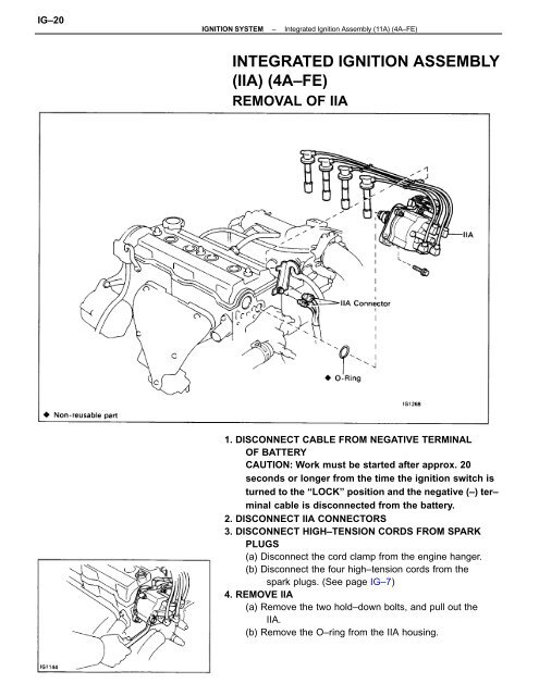
REMOVAL OF <strong>IIA</strong><br />
1. DISCONNECT CABLE FROM NEGATIVE TERMINAL<br />
OF BATTERY<br />
CAUTION: Work must be started after approx. 20<br />
seconds or longer from the time the ignition switch is<br />
turned to the “LOCK” position and the negative (–) ter–<br />
minal cable is disconnected from the battery.<br />
2. DISCONNECT <strong>IIA</strong> CONNECTORS<br />
3. DISCONNECT HIGH–TENSION CORDS FROM SPARK<br />
PLUGS<br />
(a) Disconnect the cord clamp from the engine hanger.<br />
(b) Disconnect the four high–tension cords from the<br />
spark plugs. (See page IG–7)<br />
4. REMOVE <strong>IIA</strong><br />
(a) Remove the two hold–down bolts, and pull out the<br />
<strong>IIA</strong>.<br />
(b) Remove the O–ring from the <strong>IIA</strong> housing.
<strong>IGNITION</strong> SYSTEM<br />
–<br />
Integrated Ignition Assembly (11A) (<strong>4A–FE</strong>)<br />
IG–21<br />
COMPONENTS<br />
DIS<strong>ASSEMBLY</strong> OF <strong>IIA</strong><br />
1. REMOVE <strong>IIA</strong> CAP WITHOUT DISCONNECTING<br />
HIGH–TENSION CORDS<br />
2. REMOVE ROTOR<br />
3. REMOVE <strong>IGNITION</strong> COIL DUST COVER<br />
4. REMOVE IGNITER DUST COVER<br />
5. REMOVE <strong>IGNITION</strong> COIL<br />
(a) Remove the two nuts, and disconnect the three<br />
wires from the ignition coil terminals.<br />
(b) Remove the four screws, ignition coil and gasket.
IG–22<br />
<strong>IGNITION</strong> SYSTEM<br />
–<br />
Integrated Ignition Assembly (11A) (<strong>4A–FE</strong>)<br />
6. REMOVE IGNITER<br />
(a) Remove the two nuts, and disconnect the three<br />
wires from the ignite terminals.<br />
(b) Remove the two screws and igniter.<br />
7. REMOVE <strong>IIA</strong> WIRE<br />
(a) Disconnect the connector from the cord clamp.<br />
(b) Disconnect the wire grommet from the <strong>IIA</strong> housing.<br />
(c) Remove the screw and <strong>IIA</strong> wire.<br />
INSPECTION OF <strong>IIA</strong><br />
INSPECT GOVERNOR SHAFT<br />
Turn the governor shaft and check that it is not rough or<br />
worn.<br />
If it feels rough or worn, replace the <strong>IIA</strong> housing assem–<br />
bly.<br />
<strong>ASSEMBLY</strong> OF <strong>IIA</strong><br />
(See page IG–21)<br />
1. INSTALL <strong>IIA</strong> WIRE<br />
(a) Fit the wire grommet to the <strong>IIA</strong> housing.<br />
(b) Install the <strong>IIA</strong> wire with the screw.<br />
(c) Install the connector to the cord clamp.<br />
2. INSTALL IGNITER<br />
(a) Install the igniter with the two screws.
<strong>IGNITION</strong> SYSTEM<br />
–<br />
Integrated Ignition Assembly (11A) (<strong>4A–FE</strong>)<br />
IG–23<br />
(b) Connect the three wires to the igniter terminals with<br />
the three screws.<br />
3. INSTALL <strong>IGNITION</strong> COIL<br />
(a) Install the gasket and ignition coil with the four<br />
screws.<br />
(b) Connect the three wires to the ignition coil terminals<br />
with the two nuts.<br />
NOTICE:<br />
• When connecting the wires to the ignition coil, in–<br />
sert both properly into their grooves found on the<br />
side of the ignition coil.<br />
• Be sure the wires do not contact with signal rotor or<br />
<strong>IIA</strong> housing.<br />
4. INSTALL <strong>IGNITION</strong> COIL DUST COVER<br />
5. INSTALL ROTOR<br />
6. INSTALL <strong>IIA</strong> CAP AND HIGH–TENSION CORDS
IG–24<br />
<strong>IGNITION</strong> SYSTEM<br />
–<br />
Integrated Ignition Assembly (11A) (<strong>4A–FE</strong>)<br />
INSTALLATION OF <strong>IIA</strong><br />
(See page IG–20)<br />
1. SET NO.1 CYLINDER TO TDC/COMPRESSION<br />
Turn the crankshaft clockwise, and position the slit of the<br />
intake camshaft as shown in the illustration.<br />
2. INSTALL <strong>IIA</strong><br />
(a) Install a new O–ring to the housing.<br />
(b) Apply a light coat of engine oil on the O–ring.<br />
(c) Align the cutout of the coupling with the line of the<br />
housing.<br />
(d) Insert the <strong>IIA</strong>, aligning the center of the flange with<br />
that of bolt hole on the cylinder head.<br />
(e) Lightly tighten the two hold–down bolts.<br />
3. CONNECT HIGH–TENSION CORDS TO SPARK PLUGS<br />
Firing order: 1 – 3 – 4 – 2<br />
4. CONNECT <strong>IIA</strong> CONNECTORS<br />
5. CONNECT CABLE TO NEGATIVE TERMINAL OF<br />
BATTERY<br />
6. WARM UP ENGINE<br />
Allow the engine to warm up to normal operating tem–<br />
perature.<br />
7. CONNECT TACHOMETER<br />
Connect the test probe of a tachometer to terminal IG¿¿of the<br />
data link connector 1.<br />
NOTICE:<br />
• NEVER allow the tachometer terminal to touch ground<br />
as it could result in damage to the igniter<br />
and/or ignition coil.<br />
• As some tachometers are not compatible with this<br />
ignition system, we recommend that you confirm<br />
the compatibility of your unit before use.
<strong>IGNITION</strong> SYSTEM<br />
–<br />
Integrated Ignition Assembly (11A) (<strong>4A–FE</strong>)<br />
IG–25<br />
8. ADJUST <strong>IGNITION</strong> TIMING<br />
(a) Using SST, connect terminals TE1 and E1 of the<br />
data link connector 1.<br />
SST 09843–18020<br />
(b) Using a timing light, check the ignition timing.<br />
Ignition timing: 10 BTDC @ idle<br />
(Transmission in neutral range)<br />
(c) Loosen the two hold–down bolts, and adjust by<br />
turning the <strong>IIA</strong>.<br />
(d) Tighten the hold–down bolts, and recheck the igni–<br />
tion timing.<br />
Torque: 20 N–m (200 kgf–cm,14 ft–lbf)<br />
(e) Remove the SST.<br />
SST 09843–18020<br />
9. FURTHER CHECK <strong>IGNITION</strong> TIMING<br />
Ignition timing: 0 – 20 BTDC @ idle<br />
(Transmission in neutral range)<br />
HINT: The timing mark moves in a range between 0°<br />
and 20°.<br />
10. DISCONNECT TACHOMETER AND TIMING LIGHT<br />
FROM ENGINE


