HELICA - Veterinary Instrumentation
HELICA - Veterinary Instrumentation
HELICA - Veterinary Instrumentation

You also want an ePaper? Increase the reach of your titles
YUMPU automatically turns print PDFs into web optimized ePapers that Google loves.
8 TOTAL JOINT REPLACEMENT<br />
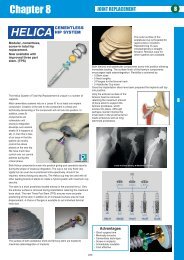
<strong>HELICA</strong> Surgical Technique<br />
Pre-operative assessment and planning<br />
gives the predicted size of cup, stem and<br />
head / neck.<br />
The acetabulum is prepared by reaming<br />
with progressively larger and larger<br />
reamers finishing with the predicted size.<br />
Using the insertion T grip and alignment<br />
aid the threaded shell for the<br />
acetabulum is positioned ready for<br />
insertion. The threads on the shell are<br />
self tapping and are firmly screwed into<br />
position. After assessment the shell<br />
may be re-positioned if necessary.<br />
The extension pin is added to the<br />
chosen stem to ensure correct<br />
alignment of the stem in the<br />
femoral neck. The stem is slowly<br />
screwed into position until the tip<br />
exits the lateral cortex. The fine<br />
thread at the neck of the stem<br />
should sit below the resection<br />
line. The milling tool will remove<br />
excess bone to leave the<br />
resection line at right angles to<br />
the stem.<br />
The axis is determined in part by eye but<br />
aided by a goniometer. The axis is<br />
established initially by a small drill which is<br />
progressively opened using larger and larger<br />
drills.<br />
The resection of the femoral head<br />
is made just distal to the bonecartilage<br />
interface. The resection<br />
is made perpendicular to the<br />
femoral stem implant axis. The<br />
face of the osteotomy will be<br />
milled at a later stage to ensure<br />
that the bed for the femoral<br />
component flange is aligned<br />
correctly. The osteotomy is<br />
facilitated by use of the Helica<br />
hohman to lift the femoral head.<br />
The milling tool prepares the bone surface for the<br />
flangewhich sits on and spreads the load onto the<br />
femoral neck. The new stem design ensures that<br />
the flange will always sit squarely on the milled<br />
area. The flange is fitted and locked in position by<br />
a locking ring.<br />
The cup inlay is a click fit into the<br />
acetabular shell. Insertion is<br />
accomplished using an insertion tool.<br />
The rim of the inlay should sit flush<br />
with the shell margin.<br />
After trialling, the appropriate<br />
femoral head is locked onto<br />
the femoral neck. The<br />
interface is a very secure<br />
morse taper. Hybrid heads<br />
are available to fit other hip<br />
systems to allow the use of<br />
the Helica cup when revising<br />
other system cup failures.<br />
The selected<br />
head is fitted.<br />
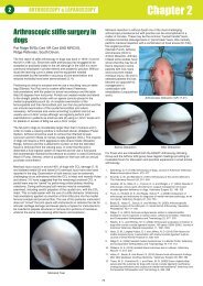
The femoral component must be inserted along the axis of the femoral<br />
neck. It is important to spend time establishing the correct axis.<br />
A CCD angle of 145 to 147 degrees is desirable.<br />
Much thought and care should be taken when placing the initial 2.0 or<br />
2.5mm drill hole which should exit the lateral cortex. Drills of increasing<br />
size are used to open up the femoral neck. Each drill should exit the lateral<br />
cortex. The final drill for the femoral neck will be the pilot drill for the<br />
predicted femoral component.<br />
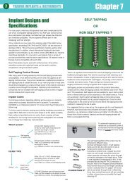
Correct positioning of the implants<br />
is confirmed by radiography.<br />
This surgical guide is included to give an<br />
over view of the technique. Surgeons<br />
contemplating use of the Helica system<br />
must attend a recognised training course. A<br />
fuller illustrated guide is included.<br />
198