490 ECHO SOUNDER INSTALLATION MANUAL
490 ECHO SOUNDER INSTALLATION MANUAL
490 ECHO SOUNDER INSTALLATION MANUAL

Create successful ePaper yourself
Turn your PDF publications into a flip-book with our unique Google optimized e-Paper software.
<strong>490</strong> <strong>ECHO</strong> <strong>SOUNDER</strong><br />
<strong>INSTALLATION</strong> <strong>MANUAL</strong><br />
Rev B2<br />
Part Number GM491<br />
Northstar Technologies<br />
30 Sudbury Road<br />
Acton, Massachusetts 01720<br />
www.NorthstarNav.com<br />
Service: 978/897-0770<br />
Sales: 978/897-6600
Limited warranty policy<br />
Northstar Technologies, Inc., warrants the Northstar <strong>490</strong> to be free from defects in materials and<br />
workmanship for a period of two (2) years. This warranty applies to the original purchaser and to any<br />
subsequent owner during the warranty period, which begins on the date of shipment of the unit,<br />
F.O.B. Acton, Massachusetts, to an authorized Northstar dealer.<br />
Systems may not be returned to Northstar without a Returned Materials Authorization (RMA) number.<br />
Call the Northstar dealer or Northstar for instructions.<br />
During the unit’s warranty period, Northstar will repair or replace, at its option, any part of the unit it<br />
finds to be defective due to faulty material(s) or workmanship. All such repairs and/or replacements<br />
will be promptly performed by Northstar free-of-charge to the owner, excluding freight costs<br />
incurred in shipping to the factory. Return shipments from Northstar to points within the United<br />
States are made via ground transportation, freight prepaid. Special shipping charges (overnight,<br />
two-day, and so on) are the responsibility of the owner.<br />
To be covered by this warranty, the Northstar equipment must have been in normal use. This warranty<br />
does not apply to units with defects caused by improper installation, physical damage, abuse,<br />
tampering, lightning or other abnormal electrical discharge, or to units with defaced or altered serial<br />
numbers, or to units repaired by unauthorized persons or repaired in a manner that violates Northstar’s<br />
recommended service procedures.<br />
All repairs and/or replacements made under this warranty must be performed at Northstar’s facilities<br />
in Acton, Massachusetts. Performance of warranty work elsewhere will not be authorized, and Northstar<br />
will not pay for any charges for such work. Northstar will not be responsible for payment of any<br />
charges imposed by a Northstar dealer or other party for services requested by and/or performed for<br />
a unit’s owner in connection with this warranty. Such services might include removal of the unit<br />
from a vessel, inspection, packaging, handling, reinstallation, and the like.<br />
Northstar Technologies assumes no responsibility for any consequential losses of any nature with<br />
respect to any of its products or services sold, rendered, or delivered. The foregoing is the only warranty<br />
expressed or implied. No other warranty exists.
Table of Contents<br />
SECTION ONE Introduction . . . . . . . . . . . . . . . . . . . . . . . . . . . . . . . . . . . . . . . . . . . . . . . . . . . . . . . . . . . . . . . . . . . . . . . . .1<br />
Welcome to the Northstar <strong>490</strong> . . . . . . . . . . . . . . . . . . . . . . . . . . . . . . . . . . . . . . . . . . . . . . . . . . . . . . . . .1<br />
Who should read this manual . . . . . . . . . . . . . . . . . . . . . . . . . . . . . . . . . . . . . . . . . . . . . . . . . . . . . . . . . .2<br />
Scope of this manual . . . . . . . . . . . . . . . . . . . . . . . . . . . . . . . . . . . . . . . . . . . . . . . . . . . . . . . . . . . . . . . . . .2<br />
Installation considerations . . . . . . . . . . . . . . . . . . . . . . . . . . . . . . . . . . . . . . . . . . . . . . . . . . . . . . . . . . . . .2<br />
SECTION TWO Installing the transducer. . . . . . . . . . . . . . . . . . . . . . . . . . . . . . . . . . . . . . . . . . . . . . . . . . . . . . . . . . . . .5<br />
Safety considerations. . . . . . . . . . . . . . . . . . . . . . . . . . . . . . . . . . . . . . . . . . . . . . . . . . . . . . . . . . . . . . . . . .5<br />
Selecting a transducer . . . . . . . . . . . . . . . . . . . . . . . . . . . . . . . . . . . . . . . . . . . . . . . . . . . . . . . . . . . . . . . . .6<br />
Installation considerations . . . . . . . . . . . . . . . . . . . . . . . . . . . . . . . . . . . . . . . . . . . . . . . . . . . . . . . . . . . . .7<br />
Choosing a mounting location . . . . . . . . . . . . . . . . . . . . . . . . . . . . . . . . . . . . . . . . . . . . . . . . . . . . . . . . .7<br />
Installing a transducer . . . . . . . . . . . . . . . . . . . . . . . . . . . . . . . . . . . . . . . . . . . . . . . . . . . . . . . . . . . . . . .10<br />
Maintaining a transducer . . . . . . . . . . . . . . . . . . . . . . . . . . . . . . . . . . . . . . . . . . . . . . . . . . . . . . . . . . . . .11<br />
SECTION THREE Installing the <strong>490</strong> . . . . . . . . . . . . . . . . . . . . . . . . . . . . . . . . . . . . . . . . . . . . . . . . . . . . . . . . . . . . . . . . 13<br />
Safety considerations. . . . . . . . . . . . . . . . . . . . . . . . . . . . . . . . . . . . . . . . . . . . . . . . . . . . . . . . . . . . . . . . .13<br />
System components. . . . . . . . . . . . . . . . . . . . . . . . . . . . . . . . . . . . . . . . . . . . . . . . . . . . . . . . . . . . . . . . . .14<br />
Choosing a mounting location . . . . . . . . . . . . . . . . . . . . . . . . . . . . . . . . . . . . . . . . . . . . . . . . . . . . . . . .15<br />
Mounting the <strong>490</strong> . . . . . . . . . . . . . . . . . . . . . . . . . . . . . . . . . . . . . . . . . . . . . . . . . . . . . . . . . . . . . . . . . . .16<br />
Wiring the <strong>490</strong> . . . . . . . . . . . . . . . . . . . . . . . . . . . . . . . . . . . . . . . . . . . . . . . . . . . . . . . . . . . . . . . . . . . . . .17<br />
Powering up, setting up, and powering down the <strong>490</strong> . . . . . . . . . . . . . . . . . . . . . . . . . . . . . . . . . . . .21<br />
Installation-test checklist . . . . . . . . . . . . . . . . . . . . . . . . . . . . . . . . . . . . . . . . . . . . . . . . . . . . . . . . . . . . .22<br />
SECTION FOUR Troubleshooting and servicing the <strong>490</strong> . . . . . . . . . . . . . . . . . . . . . . . . . . . . . . . . . . . . . . . . . . . 23<br />
Troubleshooting common <strong>490</strong> installation problems . . . . . . . . . . . . . . . . . . . . . . . . . . . . . . . . . . . . .23<br />
Getting technical support . . . . . . . . . . . . . . . . . . . . . . . . . . . . . . . . . . . . . . . . . . . . . . . . . . . . . . . . . . . . .26<br />
Ordering replacement parts . . . . . . . . . . . . . . . . . . . . . . . . . . . . . . . . . . . . . . . . . . . . . . . . . . . . . . . . . . .27<br />
Servicing the <strong>490</strong> . . . . . . . . . . . . . . . . . . . . . . . . . . . . . . . . . . . . . . . . . . . . . . . . . . . . . . . . . . . . . . . . . . . .27<br />
Returning a <strong>490</strong> for service . . . . . . . . . . . . . . . . . . . . . . . . . . . . . . . . . . . . . . . . . . . . . . . . . . . . . . . . . . .28<br />
APPENDIX A Technical specifications . . . . . . . . . . . . . . . . . . . . . . . . . . . . . . . . . . . . . . . . . . . . . . . . . . . . . . . . . . . . . 29<br />
Glossary . . . . . . . . . . . . . . . . . . . . . . . . . . . . . . . . . . . . . . . . . . . . . . . . . . . . . . . . . . . . . . . . . . . . . . . . . . . . . . . . . . . . . . . . . . 31<br />
<strong>490</strong> <strong>INSTALLATION</strong> <strong>MANUAL</strong>, Revision B2 Page i
Page ii<br />
<strong>490</strong> <strong>INSTALLATION</strong> <strong>MANUAL</strong>, Revision B2
SECTION ONE<br />
Introduction<br />
Welcome to the<br />
Northstar <strong>490</strong><br />
An echo sounder is a device that provides information about<br />
the water directly beneath a vessel. The echo sounder system<br />
consists of:<br />
• the Northstar <strong>490</strong> echo sounder sensor<br />
• a Northstar navigation system such as the 961/962 or 957/<br />
958<br />
• a transducer<br />
The <strong>490</strong> is available in two models:<br />
• the model <strong>490</strong>-D is a 1000-watt dual channel echo<br />
sounder designed to be used with a transducer having<br />
dual ceramic elements, one each for 50 and 200 kHz<br />
• the model <strong>490</strong>-S is a 600-watt single channel echo sounder<br />
designed to be used with a transducer having a single<br />
ceramic element capable of 50 and 200 kHz<br />
In this manual, the term “<strong>490</strong>” refers to both models. For more<br />
information about the <strong>490</strong>-D and <strong>490</strong>-S, see ”System<br />
components” on page 14.<br />
<strong>490</strong> <strong>INSTALLATION</strong> <strong>MANUAL</strong>, Revision B2 Page 1
SECTION ONE Introduction<br />
Who should read<br />
this manual<br />
This manual is for marine technicians who are installing the<br />
Northstar <strong>490</strong> and connecting it with the Northstar 961/962<br />
processor or Northstar 957/958, and a transducer.<br />
Scope of this<br />
manual<br />
In this manual, you’ll find information about the following:<br />
• mounting and wiring the <strong>490</strong><br />
• connecting the <strong>490</strong> to the Northstar 961/962 or 957/958<br />
• installing a transducer (an overview is provided, but for<br />
such details as wiring, see the documentation provided by<br />
the transducer’s manufacturer)<br />
• connecting the <strong>490</strong> to a transducer (see also the<br />
Transducer Connector Instructions—GM492)<br />
• troubleshooting and testing the system<br />
• technical specifications for the <strong>490</strong><br />
For information about obtaining technical support and<br />
returning the <strong>490</strong> for factory service, see “SECTION FOUR<br />
Troubleshooting and servicing the <strong>490</strong>” beginning on page 23.<br />
For details about operating the <strong>490</strong> using the 961/962 or 957/<br />
958, see the Northstar <strong>490</strong> Echo Sounder Operations Manual<br />
(GM<strong>490</strong>).<br />
Installation<br />
considerations<br />
CAUTION!<br />
The following list of installation considerations isn’t<br />
a substitute for all the details in Section Three. To<br />
ensure that you meet all critical installation<br />
parameters, be sure to read that entire section and<br />
follow all of its recommendations.<br />
1. Check the shipping carton for any damage, and<br />
immediately report any damage to the carrier. Save all<br />
packing material in case you have to return the <strong>490</strong> to<br />
the factory for repair or evaluation.<br />
2. Unpack the carton, and check its contents. You should<br />
have received:<br />
Page 2<br />
<strong>490</strong> <strong>INSTALLATION</strong> <strong>MANUAL</strong>, Revision B2
SECTION ONE Introduction<br />
• the Northstar <strong>490</strong> Echo Sounder (-D or -S model)<br />
• 10-foot (3-meter) data cable to connect the <strong>490</strong> to the<br />
961/962 or 957/958<br />
• 10-foot (3-meter) power cable for the <strong>490</strong><br />
• <strong>490</strong> parts kit (containing transducer cable end<br />
connector, backshell, heatshrink tubing, and the<br />
Transducer Connector Instructions—GM492)<br />
• Northstar <strong>490</strong> Echo Sounder Installation Manual<br />
(GM491)<br />
• Northstar <strong>490</strong> Echo Sounder Operations Manual<br />
(GM<strong>490</strong>)<br />
• warranty card<br />
3. Fill out the warranty card and mail it to Northstar.<br />
4. Review all of the installation requirements as outlined in<br />
Sections Two and Three.<br />
5. Install the transducer, then terminate the cable (see<br />
”Connecting the <strong>490</strong> to a transducer” starting on page<br />
20).<br />
6. Mount the <strong>490</strong>. For instructions, see ”Mounting the <strong>490</strong>”<br />
on page 16.<br />
7. Connect the <strong>490</strong> to ship’s power and to the 961/962<br />
processor or the 957/958. Connection information begins<br />
on page 17.<br />
With the vessel in the water, turn on the system and verify<br />
proper operation.<br />
<strong>490</strong> <strong>INSTALLATION</strong> <strong>MANUAL</strong>, Revision B2 Page 3
SECTION ONE Introduction<br />
Page 4<br />
<strong>490</strong> <strong>INSTALLATION</strong> <strong>MANUAL</strong>, Revision B2
SECTION TWO<br />
Installing the<br />
transducer<br />
Safety<br />
considerations<br />
WARNING!<br />
Be sure to turn the power off before starting the<br />
installation. Further, it is highly recommended that<br />
you keep power off while you’re performing the<br />
installation. If power is left on or turned on during<br />
the installation, fire, electrical shock, or other<br />
serious injury may occur.<br />
Be sure to ground the equipment to prevent<br />
electrical shock and mutual interference.<br />
Be sure the transducer outputs are tied together<br />
before handling to avoid electrical charge build-up.<br />
WARNING!<br />
Be sure to use a 3-amp fuse. Using the incorrect<br />
fuse can result in fire or damage to the <strong>490</strong>.<br />
<strong>490</strong> <strong>INSTALLATION</strong> <strong>MANUAL</strong>, Revision B2 Page 5
SECTION TWO Installing the transducer<br />
CAUTION!<br />
Mounting the transducer requires drilling holes<br />
through the hull; make sure the installation does not<br />
cause the vessel to leak. A thru-hull installation<br />
should be performed by a professional installer. Do<br />
not attempt this unless you are fully qualified.<br />
Do not perform a thru-hull installation of the<br />
transducer when the vessel is actually in the water.<br />
Immediately after installing the transducer, be sure<br />
to check for leaks, and don’t leave the vessel in the<br />
water for more than three hours before checking it<br />
again.<br />
Northstar assumes no responsibility for improper<br />
installation of a transducer.<br />
NOTE:<br />
Be sure that the transducer doesn’t interfere with<br />
any of the on-board systems. Check all other<br />
systems to ensure that their performance doesn’t<br />
degrade when the transducer is connected.<br />
Selecting a<br />
transducer<br />
Northstar recommends using an Airmar transducer with the<br />
Northstar’s <strong>490</strong> echo sounder.<br />
Table 1: Northstar-recommended transducers<br />
Manufacturer Housing Power Frequency<br />
Airmar<br />
Airmar<br />
B250<br />
(P/N 41-088-1-01)<br />
B744V/B44V (with<br />
3-wire speed)<br />
1 kW 50/200 kHz<br />
600 W 50/200 kHz<br />
Page 6<br />
<strong>490</strong> <strong>INSTALLATION</strong> <strong>MANUAL</strong>, Revision B2
SECTION TWO Installing the transducer<br />
To purchase a single transducer, contact GEM Electronics at:<br />
GEM Electronics Company<br />
110 South Acline Avenue<br />
Lake City, South Carolina 29560<br />
Phone 843/394-3565<br />
Fax 843/394-3736<br />
If you are a dealer and want to purchase multiple transducers,<br />
you can reach Airmar Technology Corporation at:<br />
Airmar Technology Corporation (www.airmar.com)<br />
35 Meadowbrook Drive<br />
Milford, New Hampshire 03055-4613<br />
Phone 603/673-9570<br />
Fax 603/673-4624<br />
For a list of transducers that are compatible with the Northstar<br />
<strong>490</strong>, visit Northstar’s website at:<br />
www.NorthstarNav.com<br />
Installation<br />
considerations<br />
The following basic setup information isn’t a substitute for the<br />
installation instructions provided by the transducer’s<br />
manufacturer. To ensure that you meet all critical installation<br />
parameters, be sure to read and follow all of the requirements<br />
in their instructions. Northstar assumes no responsibility for<br />
improper installation.<br />
Choosing a<br />
mounting<br />
location<br />
CAUTION!<br />
Do not mount the transducer:<br />
• behind strakes, fittings, or hull irregularities<br />
(mounting in those locations may increase<br />
turbulence, aeration, and cavitation) or near the<br />
keel<br />
• near openings for water intake or discharge<br />
• where it might be loosened by the vessel’s<br />
vibration<br />
• less than four feet away from the Northstar 961/<br />
962 processor to minimize interference<br />
<strong>490</strong> <strong>INSTALLATION</strong> <strong>MANUAL</strong>, Revision B2 Page 7
SECTION TWO Installing the transducer<br />
The two most common problems with echo sounder<br />
installations stem from noise and cavitation. Either of these<br />
situations can produce poor performance.<br />
Noise occurs when the transducer cable is routed too closely to<br />
noise-producing electronics, such as alternators, AC generators,<br />
radars, etc. To avoid problems with noise, route the transducer<br />
cable by itself (not in a bundle) and away from other wires or<br />
cables and the engine.<br />
Cavitation is similar to hydroplaning. In some cases, air bubbles<br />
will come between the transducer and the water. When this<br />
happens, the transducer can’t get its energy into the water<br />
properly, and won’t be able to detect any echoes. To avoid<br />
cavitation, choose a mounting location with good water flow all<br />
around it at all speeds.<br />
Choose the mounting<br />
location to obtain the best<br />
possible performance from<br />
the transducer and the <strong>490</strong>.<br />
Take into account the<br />
vessel’s maximum speed<br />
when selecting a mounting<br />
location, as turbulence can<br />
affect echo sounding<br />
capabilities.<br />
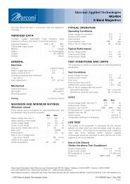
Before any drilling or cutting takes place, carefully choose a<br />
mounting location for the transducer that meets the following<br />
criteria (also see Figure 1 on page 9), depending on the type of<br />
vessel:<br />
• the transducer and its cable are as far as possible from<br />
other electrical cables<br />
• leaves room above the transducer for the transducer’s<br />
stem, housing, and cable<br />
• the path for running the transducer’s cable is reasonably<br />
direct—keep in mind that the transducer cable is 33 feet<br />
long (10 meters). To prevent damage, coil any excess cable<br />
and secure it<br />
• water turbulence and noise are minimal, decreasing the<br />
amount of bubbles passing over the transducer face<br />
• the transducer isn’t behind hull irregularities or near<br />
eroding paint; both indicate areas subject to turbulence<br />
• the transducer is as far as possible from the engine or<br />
propellers, and inboard of the lifting strakes<br />
• the transducer always remains submerged and<br />
perpendicular to the waterline<br />
• the transducer is easily accessible from inside the vessel<br />
for adjustments and maintenance<br />
• the transducer’s ultrasonic beams aren’t obstructed by the<br />
keel, propeller shafts, or any other part of the vessel<br />
• the transducer is parallel with the water surface<br />
• the hull thickness falls within the limits in Table 2 below<br />
(all dimensions are perpendicular to the waterline):<br />
Page 8<br />
<strong>490</strong> <strong>INSTALLATION</strong> <strong>MANUAL</strong>, Revision B2
SECTION TWO Installing the transducer<br />
Table 2: Hull thickness limits<br />
Model Minimum Maximum<br />
AirMar B44V/B744V with fairing 6 mm (1/4 inch) 19 mm (3/4 inch)<br />
AirMar B44V/B744V without fairing 6 mm (1/4 inch) 65 mm (2 1/2 inches)<br />
AirMar B250 with fairing —— 45 mm (1 3/4 inches)<br />
AirMar B250 without fairing 19 mm (3/4 inch) 114 mm (4 1/2 inches)<br />
pressure waves<br />
1/3 aft<br />
LWL<br />
(Load Waterline Length)<br />
displacement hull<br />
150-300mm<br />
(6-12")<br />
outboard and I/O<br />
planning hulls<br />
inboard<br />
step-hull<br />
fin keel sailboat<br />
full keel sailboat<br />
Best location for the transducer<br />
Figure 1: Recommended installation locations for a transducer<br />
<strong>490</strong> <strong>INSTALLATION</strong> <strong>MANUAL</strong>, Revision B2 Page 9
SECTION TWO Installing the transducer<br />
Installing a<br />
transducer<br />
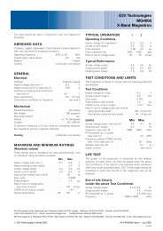
A flat-bottom hull provides the best environment for mounting<br />
the transducer: It provides a horizontal surface and a constant<br />
water flow over the transducer, with little turbulence (see<br />
Figure 2 for the recommended transducer incline angle). If the<br />
vessel has a deadrise angle greater than 5 degrees, mount the<br />
transducer on a fairing block to create a horizontal surface and<br />
keep the transducer perpendicular to the waterline (see<br />
Figure 3). You must order the fairing block, if needed, from the<br />
transducer’s manufacturer.<br />
3° incline<br />
angle<br />
LWL<br />
(Load Waterline Length)<br />
1/3 aft<br />
Figure 2: Recommended transducer incline angle<br />
backing<br />
block<br />
hull<br />
fairing thickness<br />
at narrowest point<br />
6–12mm (1/4–1/2")<br />
fairing<br />
multisensor<br />
slope of hull<br />
deadrise<br />
angle<br />
parallel to<br />
waterline<br />
Deadrise angle and fairing thickness (B44V shown)<br />
Figure 3: Typical finished thru-hull installation with a fairing block (Airmar B44V)<br />
Page 10<br />
<strong>490</strong> <strong>INSTALLATION</strong> <strong>MANUAL</strong>, Revision B2
SECTION TWO Installing the transducer<br />
Maintaining a<br />
transducer<br />
Do not expose the transducer’s face or plastic housing to<br />
gasoline or strong solvents, such as acetone. These solvents can<br />
penetrate and degrade many plastics and reduce their strength.<br />
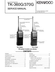
Using anti-fouling paint<br />
The transducer should be coated with water-based anti-fouling<br />
paint to prevent aquatic growth.<br />
housing<br />
paddle wheel<br />
insert<br />
Paint exposed housing<br />
and bore up 30mm (1-1/4")<br />
detail<br />
lower<br />
O-ring<br />
Paint outside wall below the lower O-ring<br />
including exposed end, paddle wheel cavity and paddle wheel<br />
Anti-fouling paint (B44V shown)<br />
Figure 4: Anti-fouling paint areas (for Airmar B44V)<br />
CAUTION!<br />
Use special transducer paint. Other paints may<br />
contain copper, which is conductive and can burn<br />
out the transducer within minutes!<br />
Cleaning a transducer<br />
To clean the transducer of heavy debris or foul sea growth, use<br />
a stiff brush or putty knife, but don’t scratch the surfaces.<br />
Check the transducer every few weeks, maximum.<br />
Use sanding sparingly, as repeated sanding may affect the<br />
transducer’s performance at high speeds. For lighter cleaning,<br />
the surface may be wet-sanded with #220 or finer wet/dry<br />
sandpaper.<br />
<strong>490</strong> <strong>INSTALLATION</strong> <strong>MANUAL</strong>, Revision B2 Page 11
SECTION TWO Installing the transducer<br />
Page 12<br />
<strong>490</strong> <strong>INSTALLATION</strong> <strong>MANUAL</strong>, Revision B2
SECTION THREE<br />
Installing the<br />
<strong>490</strong><br />
Safety<br />
considerations<br />
WARNING!<br />
Be sure to turn the power off before starting the<br />
installation. Further, it is highly recommended that<br />
you keep the power off while you’re performing the<br />
installation. If power is left on or turned on during<br />
the installation, then fire, electrical shock, or other<br />
serious injury may occur.<br />
Be sure to ground the equipment to prevent<br />
electrical shock and mutual interference.<br />
Be sure that the voltage of the power supply is<br />
between 10 and 30 volts DC. Connecting to the<br />
wrong power supply can result in fire or damage to<br />
equipment.<br />
Be sure to use a 3-amp fuse. Using the incorrect<br />
fuse can result in fire or damage to the <strong>490</strong>.<br />
CAUTION!<br />
Keep the following safe compass distances from<br />
the <strong>490</strong>: 1.0 m standard, 0.8 m steering.<br />
<strong>490</strong> <strong>INSTALLATION</strong> <strong>MANUAL</strong>, Revision B2 Page 13
SECTION THREE Installing the <strong>490</strong><br />
CAUTION!<br />
Be sure that the <strong>490</strong> doesn’t interfere with any of<br />
the on-board systems. Check all other systems to<br />
ensure that their performance doesn’t degrade<br />
when the <strong>490</strong> is turned on.<br />
If the vessel is out of the water when the echo<br />
sounder is turned on, the transducer may be<br />
damaged.<br />
CAUTION!<br />
Do not open the <strong>490</strong>. There are no serviceable<br />
parts inside. Unauthorized tampering with the unit<br />
will automatically void the warranty.<br />
System<br />
components<br />
Figure 5 on page 14 shows a configured 961/962 echo sounder<br />
system, and Figure 6 on page 15 shows a configured 957/958<br />
echo sounder system.<br />
GPS/DGPS<br />
ANTENNA<br />
NORTHSTAR<br />
961/962<br />
DISPLAY<br />
10-FOOT CABLE<br />
(NORTHSTAR-SUPPLIED)<br />
33-FOOT CABLE<br />
(PART OF TRANSDUCER)<br />
NORTHSTAR<br />
961/962<br />
PROCESSOR<br />
DATA<br />
INTERFACE<br />
NORTHSTAR<br />
<strong>490</strong> <strong>ECHO</strong><br />
<strong>SOUNDER</strong><br />
SHIP’S POWER<br />
10-FOOT CABLE<br />
(NORTHSTAR-SUPPLIED)<br />
TRANSDUCER<br />
RECOMMENDED:<br />
AIRMAR B250 1000-W TRANSDUCER<br />
FOR THE <strong>490</strong>-D<br />
AIRMAR B44V/B744V 600-W TRANSDUCER<br />
FOR THE <strong>490</strong>-S<br />
Figure 5: 961/962 echo sounder system components<br />
Page 14<br />
<strong>490</strong> <strong>INSTALLATION</strong> <strong>MANUAL</strong>, Revision B2
SECTION THREE Installing the <strong>490</strong><br />
NORTHSTAR<br />
2201 GPS<br />
10-FOOT CABLE<br />
(NORTHSTAR-SUPPLIED)<br />
33-FOOT CABLE<br />
(PART OF TRANSDUCER)<br />
NORTHSTAR<br />
957/958<br />
POWER AND DATA<br />
INTERFACE<br />
NORTHSTAR<br />
<strong>490</strong> <strong>ECHO</strong><br />
<strong>SOUNDER</strong><br />
SHIP’S POWER<br />
10-FOOT CABLE<br />
(NORTHSTAR-SUPPLIED)<br />
TRANSDUCER<br />
RECOMMENDED:<br />
AIRMAR B250 1000-W TRANSDUCER<br />
FOR THE <strong>490</strong>-D<br />
AIRMAR B44V/B744V 600-W TRANSDUCER<br />
FOR THE <strong>490</strong>-S<br />
Figure 6: 957/958 echo sounder system components<br />
Choosing a<br />
mounting<br />
location<br />
Before any drilling or cutting takes place, carefully choose a<br />
mounting location for the <strong>490</strong> that meets the following criteria:<br />
• where the transducer is more than four feet away from the<br />
Northstar 961/962 or 957/958, to prevent mutual electrical<br />
and magnetic interference<br />
• where the transducer cable is kept securely away from<br />
other wires<br />
• where the path for running the required electrical cabling<br />
is reasonably direct; keep in mind the different cable<br />
lengths<br />
• where the <strong>490</strong> won’t be exposed to water<br />
<strong>490</strong> <strong>INSTALLATION</strong> <strong>MANUAL</strong>, Revision B2 Page 15
SECTION THREE Installing the <strong>490</strong><br />
Mounting the <strong>490</strong> Figure 7 below shows the mounting dimensions for the <strong>490</strong>.<br />
The <strong>490</strong> may be mounted either horizontally or vertically.<br />
The keyhole slots make installation in hard-to-reach areas<br />
easier, but be sure to tighten all mounting screws securely.<br />
Leave room for installing and removing cables, and be sure you<br />
can see the STAT (status) indicator light. This light illuminates<br />
when the <strong>490</strong>’s power is on, and is helpful when<br />
troubleshooting.<br />
Figure 7: <strong>490</strong> mounting dimensions and connector locations<br />
Page 16<br />
<strong>490</strong> <strong>INSTALLATION</strong> <strong>MANUAL</strong>, Revision B2
SECTION THREE Installing the <strong>490</strong><br />
Wiring the <strong>490</strong><br />
CAUTION!<br />
Make sure that fuse or circuit-breaker protection is<br />
provided at the power source.<br />
The majority of installation problems are caused by shortcuts<br />
taken with system cables. When installing the <strong>490</strong>, be sure that<br />
you:<br />
• assemble connectors carefully<br />
• don’t make sharp bends in the cables<br />
• leave service and drip loops, so that moisture won’t run<br />
down the cables and into the <strong>490</strong> or the 961/962 or 957/<br />
958<br />
• tie-wrap all cables to keep them secure<br />
• if cables are shortened, lengthened (not recommended), or<br />
re-terminated, seal all wiring splices<br />
• prevent interference from the transducer cable<br />
Electrical power<br />
requirements<br />
The <strong>490</strong> is a negative-ground system that is reverse-polarity<br />
and overvoltage protected. The unit requires 10 to 30 VDC<br />
power at 8 Watts.<br />
Connecting the <strong>490</strong> to ship’s<br />
power<br />
The connection between ship’s power and the <strong>490</strong> requires the<br />
10-foot (3-meter) power cable supplied by Northstar.<br />
The wires in the power cable must be connected as follows<br />
(black and white can be connected together at the power<br />
source):<br />
• Red → Positive (+) (fused lead)<br />
• Black → Negative (–)<br />
• Green → Ground (earth)<br />
NOTE:<br />
The <strong>490</strong> should be grounded to the vessel to<br />
eliminate interference. Secure either the green wire<br />
or a ground wire from the <strong>490</strong>’s grounding terminal<br />
(on the far right side of the unit) to the vessel’s<br />
nearest grounding point. Without an earth<br />
grounding, performance may be degraded.<br />
<strong>490</strong> <strong>INSTALLATION</strong> <strong>MANUAL</strong>, Revision B2 Page 17
SECTION THREE Installing the <strong>490</strong><br />
Connecting the <strong>490</strong> to the<br />
961/962<br />
The connection between the 961/962 and the <strong>490</strong> requires the<br />
10-foot (3-meter) data cable supplied by Northstar. The cable<br />
connects to the P1 slot on the back of the 961/962.<br />
Figure 8 below illustrates the wiring at the 961/962 end of the<br />
cable. Table 3 describes the pin’s functions.<br />
18<br />
961/962 P1 Connector Plug<br />
(Wiring Side View)<br />
17<br />
16<br />
15<br />
14<br />
13<br />
12<br />
11<br />
10<br />
9<br />
8<br />
7<br />
6<br />
5<br />
4<br />
3<br />
2<br />
1<br />
Green<br />
Orange<br />
White<br />
Violet<br />
Brown<br />
Black<br />
Blue<br />
Red (not<br />
connected)<br />
Data Cable<br />
Figure 8: Interface cable connection from 961/962 to <strong>490</strong><br />
Table 3: Cable connection between the 961/962 and <strong>490</strong><br />
961/962 pin number 961/962 P1 signal name Cable wire color<br />
9 Port 3 In (A) Blue<br />
10 Port 3 In (B) Black<br />
11 Ground Brown<br />
12* Port 3 Out (A) Violet<br />
12* Port 3 Out (A) White<br />
Page 18<br />
<strong>490</strong> <strong>INSTALLATION</strong> <strong>MANUAL</strong>, Revision B2
SECTION THREE Installing the <strong>490</strong><br />
Table 3: Cable connection between the 961/962 and <strong>490</strong> (cont.)<br />
961/962 pin number 961/962 P1 signal name Cable wire color<br />
13 Port 3 Out (B) Orange<br />
16 Ground Green<br />
** Not connected Red<br />
* Connector P1, pin 12 on the 961/962 requires two connections from the cable.<br />
**The red wire is not connected on the 961/962 end, and should be insulated and capped.<br />
Connecting the <strong>490</strong> to the<br />
957/958<br />
The connection between the 957/958 and the <strong>490</strong> requires the<br />
10-foot (3-meter) data cable supplied by Northstar. The cable<br />
connects to the AUX port on the back of the 957/958.<br />
Figure 9 below illustrates the wiring for the 957/958 end of the<br />
cable. Table 4 describes the pin’s functions.<br />
Brown (1)<br />
Green (1)<br />
White (2)<br />
Blue (6)<br />
Orange (5)<br />
Violet (4)<br />
Black (3)<br />
Figure 9: Interface cable connection from 957/958 to <strong>490</strong><br />
Table 4: Cable connection between the 957/958 and <strong>490</strong><br />
957/958 pin number AUX port signal name Cable wire color<br />
1* Shield/Gnd Brown<br />
1* Remote On Gnd Green<br />
2 Remote On input White<br />
3 NMEA AUX In (B) Black<br />
<strong>490</strong> <strong>INSTALLATION</strong> <strong>MANUAL</strong>, Revision B2 Page 19
SECTION THREE Installing the <strong>490</strong><br />
Table 4: Cable connection between the 957/958 and <strong>490</strong> (cont.)<br />
957/958 pin number AUX port signal name Cable wire color<br />
4 NMEA AUX Out (A) Violet<br />
5 NMEA AUX Out (B) Orange<br />
6 NMEA AUX In (A) Blue<br />
* Pin 1 on the 957/958 AUX port requires two connections from the cable.<br />
The red wire is not connected on the 957/958 end, and should be insulated and capped.<br />
Connecting the <strong>490</strong> to a<br />
transducer<br />
Figure 10 below shows how to terminate the transducer cable<br />
for connection to the <strong>490</strong>. Pay close attention to whether you’re<br />
wiring a <strong>490</strong>-S or a <strong>490</strong>-D. See also the Transducer Connector<br />
Instructions (GM492).<br />
Table 5: <strong>490</strong>-to-transducer connector pin<br />
wiring<br />
Pin number<br />
Connector<br />
1 Speed signal<br />
2 Speed +V<br />
3 Speed ground<br />
4 Thermistor (temperature)<br />
5 Depth low+ (unused on <strong>490</strong>-S)<br />
6 Depth low- (unused on <strong>490</strong>-S)<br />
7 Thermistor (temperature)<br />
8 Depth high+<br />
9 Depth shields<br />
Figure 10: Wiring of transducer cable<br />
(solder-cup side of connector shown)<br />
10 Depth high-<br />
Page 20<br />
<strong>490</strong> <strong>INSTALLATION</strong> <strong>MANUAL</strong>, Revision B2
SECTION THREE Installing the <strong>490</strong><br />
Powering up,<br />
setting up, and<br />
powering down<br />
the <strong>490</strong><br />
Turning the <strong>490</strong> on For the 961/962<br />
This section assumes that the <strong>490</strong>, Northstar 961/962, and<br />
transducer are now all properly connected.<br />
To use the <strong>490</strong> echo sounder, the 961/962 must be running<br />
software version 3.0 or higher. If not, contact Northstar to<br />
obtain the upgrade CD. To install the upgrade, follow the steps<br />
on the back of the jewel box.<br />
Turning on the 961/962 processor automatically turns on the<br />
<strong>490</strong> (be sure your vessel is in the water). To turn the 961/962<br />
on, briefly press its PWR key.<br />
You must set the 961/962’s Port 3 to “<strong>490</strong>”:<br />
1. Press STAR to display the SERVICE MENU screen.<br />
2. Press PORT SETUP.<br />
3. Press PORT 3.<br />
4. Set the FORMAT option to <strong>490</strong>.<br />
The STAT (status) indicator light on the <strong>490</strong> glows steady green<br />
when the <strong>490</strong>’s power is on.<br />
For the 957/958<br />
This section assumes that the <strong>490</strong>, Northstar 957/958, and<br />
transducer are now all properly connected. Turning on the 957/<br />
958 automatically turns on the <strong>490</strong> (be sure your vessel is in<br />
the water). To turn the 957/958 on, briefly press its PWR key.<br />
You must set the 957/958’s AUX port to “<strong>490</strong>”:<br />
1. Press the STAR key to display the OPTIONS/SERVICE<br />
INFO screen, then press the PORT SETUP OPTIONS key.<br />
2. Set the AUX PORT option to <strong>490</strong>, then press the ENTER<br />
key.<br />
The STAT (status) indicator light on the <strong>490</strong> glows steady green<br />
when the <strong>490</strong>’s power is on.<br />
<strong>490</strong> <strong>INSTALLATION</strong> <strong>MANUAL</strong>, Revision B2 Page 21
SECTION THREE Installing the <strong>490</strong><br />
Setting up the echo sounder You’ll need to set the echo sounder display options on the 961/<br />
962 or 957/958’s <strong>ECHO</strong> <strong>SOUNDER</strong> SETUP screen. Press the<br />
STAR key to display this screen and set these options. For<br />
details, see the Northstar <strong>490</strong> Echo Sounder Operations Manual<br />
(GM<strong>490</strong>).<br />
Turning the <strong>490</strong> off<br />
To turn off the <strong>490</strong>, turn off the 961/962 or 957/958 by pressing<br />
and holding PWR until the screen goes dark. The <strong>490</strong> will turn<br />
off automatically.<br />
Installation-test<br />
checklist<br />
CAUTION!<br />
If the vessel is out of the water when the echo<br />
sounder is turned on, the transducer may be<br />
damaged. Perform all tests on the with the vessel in<br />
the water.<br />
1. Make sure the vessel is in the water.<br />
2. To test the system after installation, turn on the 961, 962,<br />
or 957/958 and confirm that power is on with no errors. If<br />
echo sounder data isn’t moving across the <strong>ECHO</strong> screen<br />
from right to left, see ”Troubleshooting common <strong>490</strong><br />
installation problems” on page 23.<br />
Page 22<br />
<strong>490</strong> <strong>INSTALLATION</strong> <strong>MANUAL</strong>, Revision B2
SECTION FOUR<br />
Troubleshooting<br />
and servicing<br />
the <strong>490</strong><br />
Troubleshooting<br />
common <strong>490</strong><br />
installation<br />
problems<br />
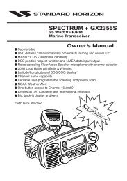
Typical problems you may encounter either during or after the<br />
<strong>490</strong> installation process are outlined in Figure 11 on page 24<br />
and Figure 12 on page 25.<br />
In the 961/962, the diagnostics screen may also help pinpoint<br />
the problem.<br />
<strong>490</strong> <strong>INSTALLATION</strong> <strong>MANUAL</strong>, Revision B2 Page 23
SECTION FOUR Troubleshooting and servicing the <strong>490</strong><br />
No echoes displayed when STAR key is pressed.<br />
Is the<br />
Advance<br />
Speed set to<br />
zero<br />
YES<br />
Change the Advance Speed<br />
setting.<br />
NO<br />
Contact Northstar Service to<br />
upgrade to the latest version<br />
of 961/962 software.<br />
NO<br />
Is the<br />
961/962<br />
software<br />
Version 3.0 or<br />
greater<br />
YES<br />
Configure NMEA Port 3 for<br />
the <strong>490</strong>. See the <strong>490</strong><br />
Operations Manual (GM<strong>490</strong>)<br />
for instructions.<br />
NO<br />
Has<br />
NMEA Port 3<br />
been configured<br />
for the <strong>490</strong><br />
YES<br />
1. Check fuses and circuit<br />
breakers<br />
2. Check power to <strong>490</strong> with<br />
a voltmeter.<br />
3. Verify that the data cable<br />
between the 961/962 and<br />
the <strong>490</strong> is properly wired<br />
and connected.<br />
OFF<br />
Check<br />
the <strong>490</strong>'s STAT<br />
indicator<br />
FLASHING<br />
STEADY<br />
ON<br />
1. Check transducer<br />
connector for the<br />
proper wiring.<br />
2. If wiring is correct,check<br />
transducer impedance<br />
with an ohmmeter.<br />
3. If the transducer is open<br />
or shorted, replace it<br />
The <strong>490</strong> and the 961/962<br />
aren't communicating properly.<br />
Check the wiring of the data<br />
cable between the 961/962<br />
and the <strong>490</strong>.<br />
ONCE<br />
PER<br />
SECOND<br />
What<br />
is the flash<br />
rate of the STAT<br />
indicator<br />
FOUR<br />
TIMES<br />
PER<br />
SECOND<br />
There's a hardware problem<br />
with the <strong>490</strong>.<br />
Figure 11: 961/962 echo sounder system troubleshooting<br />
Page 24<br />
<strong>490</strong> <strong>INSTALLATION</strong> <strong>MANUAL</strong>, Revision B2
SECTION FOUR Troubleshooting and servicing the <strong>490</strong><br />
No echoes displayed when STAR key is pressed.<br />
Is the<br />
Advance<br />
Speed set to<br />
zero<br />
Yes<br />
Change the Advance Speed<br />
setting.<br />
No<br />
Configure 957 Aux Port for<br />
the <strong>490</strong>. See the <strong>490</strong><br />
Operations Manual (GM<strong>490</strong>)<br />
for instructions.<br />
No<br />
Has<br />
957 Aux Port<br />
been configured<br />
for the <strong>490</strong><br />
Yes<br />
1. Check fuses and circuit<br />
breakers.<br />
2. Check power to <strong>490</strong> with<br />
a voltmeter.<br />
3. Verify that the data cable<br />
between the 957 and<br />
the <strong>490</strong> is properly wired<br />
and connected.<br />
Off<br />
Check<br />
the <strong>490</strong>'s STAT<br />
indicator<br />
Flashing<br />
Steady On<br />
1. Check transducer<br />
connector for the<br />
proper wiring.<br />
2. If wiring is correct,check<br />
transducer impedance<br />
with an ohmmeter.<br />
3. If the transducer is open<br />
or shorted, replace it<br />
The <strong>490</strong> and the 957 aren't<br />
communicating properly.<br />
Check the wiring of the data<br />
cable between the 957 and<br />
the <strong>490</strong>.<br />
Once per<br />
Second<br />
What<br />
is the flash<br />
rate of the STAT<br />
indicator<br />
Four Times<br />
per Second<br />
There's a hardware problem<br />
with the <strong>490</strong>.<br />
Figure 12: 957/958 echo sounder system troubleshooting<br />
<strong>490</strong> <strong>INSTALLATION</strong> <strong>MANUAL</strong>, Revision B2 Page 25
SECTION FOUR Troubleshooting and servicing the <strong>490</strong><br />
Getting technical<br />
support<br />
You can email the<br />
Northstar Service<br />
Department directly from<br />
Northstar’s website<br />
(www.NorthstarNav.com).<br />
Here, you also can access<br />
additional technical<br />
information under either<br />
the Manuals link (you can<br />
download manuals in PDF<br />
form) or Support link.<br />
After you’ve followed the instructions in this manual, if you<br />
need additional technical or operations support for the <strong>490</strong>, or<br />
if you have any other service-related questions, you can<br />
contact either your dealer or the Northstar Service Department.<br />
You can reach Northstar’s Service Department by email, fax,<br />
U.S. mail, or phone as described in Table 6 below.<br />
NOTE:<br />
Please have the following items available when you<br />
contact Northstar’s Service Department:<br />
• the <strong>490</strong>’s serial number, located on the top of<br />
the unit<br />
• the transducer manufacturer’s name and the<br />
transducer’s model and part number<br />
Please be as complete and accurate as possible when describing<br />
the problem so that a service technician can research the<br />
problem and provide the quickest response.<br />
Northstar’s Service Department is available between 9:00 AM<br />
and 5:00 PM Eastern Time, Monday through Friday, excluding<br />
major holidays.<br />
If you have questions about purchasing parts or finding an<br />
authorized Northstar dealer, or if you want basic product<br />
information and brochures, contact the Northstar Sales<br />
Department as described in the table below.<br />
Table 6: Contacting Northstar<br />
Email:<br />
Service: service@NorthstarNav.com<br />
Sales: sales@NorthstarNav.com<br />
Fax:<br />
Service: 978/897-1595<br />
Sales: 978/897-7241<br />
Telephone:<br />
Main number: 978/897-6600 or 800/628-4487<br />
Sales: 978/897-0770<br />
Service: 978/897-6600<br />
U.S. mail:<br />
30 Sudbury Road<br />
Acton, MA 01720<br />
Page 26<br />
<strong>490</strong> <strong>INSTALLATION</strong> <strong>MANUAL</strong>, Revision B2
SECTION FOUR Troubleshooting and servicing the <strong>490</strong><br />
Table 6: Contacting Northstar (cont.)<br />
Website:<br />
www.NorthstarNav.com (you can send email to<br />
Northstar directly from this site)<br />
Hearing from you<br />
Your feedback is important and helps Northstar ensure that this<br />
manual is a valuable resource for all marine technicians. Send<br />
your questions, comments, or suggestions about this manual<br />
to:<br />
docs@NorthstarNav.com<br />
Ordering<br />
replacement<br />
parts<br />
To order spare parts or replacement/missing parts, call the<br />
Northstar Sales Department at 978/897-0770.<br />
Servicing the <strong>490</strong><br />
Repair of the <strong>490</strong> is performed only at the Northstar factory.<br />
Service includes a complete hardware and software check-out.<br />
NOTE:<br />
Field repairs are not authorized and will void the<br />
warranty!<br />
For transducer service, including parts and repairs,<br />
please contact the transducer manufacturer.<br />
For a system under warranty, shipping charges to the factory<br />
are the only cost for factory repair. The repaired <strong>490</strong> will be<br />
returned via prepaid economy ground freight (units returned<br />
overseas are chargeable).<br />
The <strong>490</strong> and any accessories returned for warranty repair that<br />
are determined to be without fault are subject to a handling<br />
charge.<br />
<strong>490</strong> <strong>INSTALLATION</strong> <strong>MANUAL</strong>, Revision B2 Page 27
SECTION FOUR Troubleshooting and servicing the <strong>490</strong><br />
Returning a <strong>490</strong><br />
for service<br />
Before returning the <strong>490</strong> to<br />
the Northstar factory, to<br />
prevent delays it is critical<br />
that you first obtain a<br />
Return Materials<br />
Authorization (RMA)<br />
number from the Northstar<br />
Service Department. If the<br />
<strong>490</strong> was purchased through<br />
a dealer, call the dealer<br />
with the <strong>490</strong> serial number<br />
so they can help you get an<br />
RMA number. The <strong>490</strong>’s<br />
serial number can be found<br />
on the label at the top of the<br />
<strong>490</strong>.<br />
Shipments without a<br />
proper RMA number will<br />
not be accepted!<br />
The <strong>490</strong> is covered by a two-year hardware-only warranty,<br />
which, in summary, states that if the <strong>490</strong> is returned to the<br />
Northstar factory by the owner or dealer during the warranty<br />
period, Northstar will repair or replace, free of charge, any part<br />
found to be defective due to faulty materials or workmanship if<br />
the system has been properly installed and hasn’t been abused.<br />
See the Limited Warranty Policy at the front of this manual for<br />
further details. The only cost to the owner will be the one-way<br />
shipping charges and any associated charges that may be<br />
imposed by the dealer. If you have overnight or second-day<br />
shipping requirements, before shipping the <strong>490</strong>, please call<br />
Northstar for turnaround time, freight charges, and payment<br />
arrangements.<br />
The <strong>490</strong> should be shipped only in a properly designed carton<br />
with packing material. Shipments to the Northstar factory<br />
should be made to the following address:<br />
Northstar Technologies<br />
Service Department<br />
30 Sudbury Road<br />
Acton, MA 01720 USA<br />
NOTE:<br />
Return the transducer to its manufacturer, not to<br />
Northstar.<br />
Page 28<br />
<strong>490</strong> <strong>INSTALLATION</strong> <strong>MANUAL</strong>, Revision B2
APPENDIX A<br />
Technical<br />
specifications<br />
Table 7: <strong>490</strong> technical specifications<br />
Performance characteristics<br />
Frequencies<br />
Output power<br />
Pulse lengths<br />
Pulse repetition rate<br />
Alarms<br />
Update rate<br />
Zoom modes<br />
Auto modes<br />
Navigation data<br />
Display modes<br />
50 and 200 kHz<br />
1000 watts (<strong>490</strong>-D); 600 watts (<strong>490</strong>-S)<br />
0.1 to 2 ms<br />
30 to 600 pulses/min<br />
Fish, bottom, and temperature<br />
10 Hz maximum (depends on water depth)<br />
Marker, bottom lock, bottom lock/center, bottom<br />
Fishing or cruising<br />
Shown on bottom of screen<br />
Single/dual frequency, split-screen, four zoom<br />
modes, A-Scope<br />
Physical characteristics<br />
Dimensions<br />
Weight<br />
10 x 6.25 x 2.5 inches (including backplate)<br />
2 pounds<br />
<strong>490</strong> <strong>INSTALLATION</strong> <strong>MANUAL</strong>, Revision B2 Page 29
APPENDIX A Technical specifications<br />
Table 7: <strong>490</strong> technical specifications (cont.)<br />
Environmental characteristics<br />
Temperature<br />
Standards<br />
-25°C to +60°C operating temperature<br />
-55°C to +90°C storage temperature<br />
Waterproof, sealed design meets the following:<br />
EN60529 IP65; EN60945 emissions; CE<br />
Electrical characteristics<br />
10 to 30 VDC, 8 Watts, reverse polarity and<br />
overvoltage protection<br />
Transducer outputs protected against open circuit/<br />
short circuit<br />
Manual controls<br />
Gain<br />
0 to 75 db<br />
Clutter 0 to 9<br />
Signal level 0 to 5<br />
Noise limiter<br />
White level<br />
Range<br />
ON/OFF<br />
Background color<br />
up to 2400 feet (800 meters)<br />
Advance speed 1/8 to 2/1<br />
Depth units<br />
Installation calibrations<br />
Feet, meters, fathoms<br />
Speed, temperature, gain, transducer depth/offset<br />
Page 30<br />
<strong>490</strong> <strong>INSTALLATION</strong> <strong>MANUAL</strong>, Revision B2
Glossary<br />
cavitation<br />
The formation of bubbles, which may negatively impact a<br />
transducer’s readings by reducing its ability to put energy into<br />
the water.<br />
deadrise<br />
The rise of the bottom of a vessel above a horizontal line at the<br />
center of the vessel; that is, the slope of the hull away from the<br />
horizontal.<br />
echo sounder<br />
An instrument that uses sound waves to measure the depth of<br />
a body of water or an object (such as a school of fish) below the<br />
water’s surface.<br />
fairing block<br />
A block used to create a horizontal surface for mounting a<br />
thru-hull transducer when the vessel’s deadrise is more than 5<br />
degrees.<br />
transducer<br />
The device mounted through the hull to send and receive<br />
ultrasonic beams that determine seabed conditions and locate<br />
fish. Essentially, a transducer is an energy converter, which<br />
changes electricity to sound (send) and sound to electricity<br />
(receive).<br />
<strong>490</strong> <strong>INSTALLATION</strong> <strong>MANUAL</strong>, Revision B2 Page 31
Glossary<br />
water column<br />
An imaginary column through the water created by the path of<br />
a single transducer ping and its echoes.<br />
Page 32<br />
<strong>490</strong> <strong>INSTALLATION</strong> <strong>MANUAL</strong>, Revision B2
A<br />
Airmar Technology Corporation 7<br />
C<br />
Cable<br />
<strong>490</strong> and 957 19<br />
<strong>490</strong> and 961/962 18<br />
<strong>490</strong> and ship’s power 17<br />
Cautions<br />
installation 2, 5, 6, 13<br />
interference with <strong>490</strong> 13<br />
tampering with the <strong>490</strong> 14<br />
transducer 5, 7, 22<br />
troubleshooting the <strong>490</strong> 22<br />
wiring the <strong>490</strong> 17<br />
E<br />
Echo sounder<br />
components of system 1, 14<br />
definition of 31<br />
installation. See Installation, <strong>490</strong><br />
serial number 28<br />
setup options 22<br />
specifications 29<br />
STAT indicator light 16, 21<br />
turning off 22<br />
turning on 21<br />
wiring 17<br />
Electrical power, requirements 17<br />
F<br />
Fairing block, definition of 31<br />
G<br />
GEM Electronics Company 7<br />
I<br />
Installation<br />
<strong>490</strong><br />
cautions 2, 13, 14, 17, 22<br />
connecting to 957 19<br />
connecting to 961/962 18<br />
connecting to ship’s power 17<br />
electrical power requirements 17<br />
general considerations 2<br />
mounting dimensions 16<br />
mounting location 15<br />
overview 13<br />
safety considerations 13<br />
troubleshooting 23<br />
wiring 17<br />
transducer<br />
cautions 5, 7, 22<br />
cavitation 8<br />
hull thickness limits 8<br />
noise problems 8<br />
Index<br />
<strong>490</strong> <strong>INSTALLATION</strong> <strong>MANUAL</strong>, Revision B2 Page 33
preferred mounting location 8<br />
recommended incline angle 10<br />
thru-hull installation with a fairing block 10<br />
M<br />
Maintenance, transducer 11<br />
N<br />
Northstar <strong>490</strong> Echo Sounder. See Echo sounder<br />
Northstar 957 GPS/WAAS Chart Navigator 1, 3, 15, 21<br />
Northstar 961/962 GPS Chart Navigator 1, 3, 15, 21<br />
Northstar Technologies<br />
feedback on manuals 27<br />
sales department 26<br />
service department 26<br />
website. See Website addresses<br />
P<br />
Parts, ordering. See Technical support<br />
S<br />
Safety considerations<br />
<strong>490</strong> 13<br />
transducer 5<br />
Service. See Technical support<br />
Software upgrades, obtaining 21<br />
Specifications 29<br />
STAT (status) indicator light 16, 21<br />
T<br />
Technical support<br />
contacting Northstar 26<br />
ordering parts 27<br />
repairing the <strong>490</strong> 27<br />
repairing the transducer 27<br />
returning the <strong>490</strong> 28<br />
Transducer<br />
definition of 31<br />
installation. See Installation, transducer<br />
maintenance. See Maintenance, transducer<br />
mounting. See Installation, transducer<br />
purchasing 7<br />
recommended 6<br />
service, parts and repair 27<br />
Troubleshooting<br />
diagnostics screen 23<br />
flow chart 25<br />
installation checklist 22<br />
installation problems 23<br />
U<br />
Upgrades, obtaining software 21<br />
W<br />
Warranty for the <strong>490</strong> 3, 28<br />
Water column, definition of 32<br />
Website addresses<br />
Airmar Technology Corporation 7<br />
Northstar Technologies 7, 26, 27<br />
Page 34<br />
<strong>490</strong> <strong>INSTALLATION</strong> <strong>MANUAL</strong>, Revision B2