Line Replaceable Module (LRM) - Amphenol Aerospace
Line Replaceable Module (LRM) - Amphenol Aerospace Line Replaceable Module (LRM) - Amphenol Aerospace
Amphenol Aerospace LRM Accessories and Tools, cont. REMOVAL, REPLACEMENT & INSERTION TOOLS Introduction/ Pkg. Solutions/ Brush Contact LRM (Line Replaceable Modules) Staggered/ GEN-X Hybrids - Fiber Optics/ Hi Speed/RF/Power Options/ Accessories Ruggedized VME64x / VITA 60, 66 High Density HSB3 HDB3 Hi Speed Low Mating Force MIL-DTL-55302 Standard Brush Hybrids - Signal/Power/ Coax/Fiber Optics Docking Conn./ Accessories/Install. Brush Contact Removal, Replacement and Insertion for Backplane Staggered Grid Connectors Contacts with solder tails within backplane LRM connectors with staggered grid are not removable or replaceable. User must replace the insert assembly. Compliant tail type contacts within backplane LRM connectors with staggered grid are removable and replaceable. Instructions for removal of compliant contacts: From the back of PC board side, push contact out through the front of the connector assembly with contact removal tool #10-507941-1. Instruction for replacement/insertion of compliant contacts: Using tweezers or fingers, carefully place the replacement contact, tail first, into the appropriate contact cavity in the front of the connector. Tweezer tip must not enter sleeve. Push contact into the cavity with a flat edged rod of suitable diameter to cover entire contact sleeve circumference until contact sleeve is flush with adjacent contacts. Do not push against wires or bend sleeve. 270 VDC Power Module Removal, Replacement and Insertion for Backplane Staggered Grid Connectors 270 VDC power modules can be removed and replaced within the power insert of an LRM connector. Instructions: Using removal tool #10507924-1 with plunger retracted, push tool down over the power module from the mating end until retention tines are released. Use plunger end of tool to push power module out of the rear the connector. The power module may be re-installed by hand by pushing it from the rear of the connector. Push it forward until the retention clips snap into the power insert cavity of the shell. The size 22D power contacts within the power modules are installed and removed with tool M81969/14-01. Removal tool 10-507941-1 for removing compliant contacts from LRM backplanes Removal tool 10-507924-1 (plunger retracted) for removing 270 VDC power modules from LRM backplanes LMD/LMS Rectangular Interconnects Other Rectangular Interconnects Rack & Panel Brush Ruggedized For Module Staggered Grid Connectors: Contacts within module LRM connectors with staggered grid are not removable or replaceable. User must replace the insert assembly. Exploded view - tool 10-507924-1 has removed power module from backplane. (size 22D contacts shown removed) 40 Contact Amphenol Aerospace for more information at 800-678-0141 • www.amphenol-aerospace.com
Aid in Selection and Ordering of LRM and LRU Interconnects from Amphenol A FORM THAT CAN BE COPIED AND FAXED TO AMPHENOL Amphenol Aerospace The following are questions to be considered when inquiring about Amphenol LRM/LRU Interconnects. The answers to these questions will help the Amphenol marketing and engineering team to determine the best board level interconnect to meet your particular needs. You can copy this page and write your comments on it, and then fax it back to Amphenol Aerospace, Sidney, NY. Include your name and company information at the bottom. Fax number: 607-563-5351, Attn: LRM product marketing. Or call Amphenol at 607-563-5011 and ask for technical information on LRM products. Footprint Required: Staggered, GEN-X, NAFI, UHD, Chevron, VME or other:______________________________________________ _______________________________________________________________________________________ Contacts Required: Digital:__________________________________________________________________________________ Fiber Optic:______________________________________________________________________________ Power:__________________________________________________________________________________ RF:____________________________________________________________________________________ LVDS:__________________________________________________________________________________ Module Requirements: Heatsink Thickness:__________________________________________________________________________ Total Board Package Thickness:_____________________________________________________________ Pitch (module to module):___________________________________________________________________ Straddle Mount, Clamshell or Right Angle:______________________________________________________ Cover Attachment:________________________________________________________________________ Keying:_________________________________________________________________________________ Backplane Requirements: Termination Style:_________________________________________________________________________ Termination Stickout (Compliant or Solder):_____________________________________________________ Shell Grounding:__________________________________________________________________________ Function Requirements: Operating Voltage:______________________________ Operating Temperature:______________________ Current Rating:_____________________________ Ambient Temperature:_______________________ Mating Cycles:_____________________________ ESD: Yes or No_____________________________ Float: Yes or No____________________________ Humidity Conditions:_________________________ Function Requirements: Level of Corrosion Resistance:_________________ Vibration Requirements:______________________ Shock Requirements:________________________ EMI/EMP:_________________________________ Altitude:___________________________________ Durability:_________________________________ Salt Fog:__________________________________ Introduction/ Pkg. Solutions/ Brush Contact LRM (Line Replaceable Modules) Staggered/ Hybrids - Fiber Optics/ Options/ GEN-X Hi Speed/RF/Power Accessories Ruggedized VME 64x/ VITA 60, 66 High Density HDB3 HSB3 Hi Speed Standard Brush Hybrids - Signal/Power/ Docking Conn./ Coax/Fiber Optics Accessories/Install. Low Mating Force MIL-DTL-55302 Please fill out information below. Thank you for writing clearly. Fax to 607-563-5351, attention: LRM product marketing. First Name Last Name Phone Number Date Title Dept./Mail Stop Fax Number Company Name Address City State Zip Code Email Address Rack & Panel Brush Ruggedized LMD/LMS Rectangular Interconnects Other Rectangular Interconnects Contact Amphenol Aerospace for more information at 800-678-0141 • www.amphenol-aerospace.com 41
- Page 1 and 2: Amphenol Line Replaceable Module (L
- Page 3 and 4: Amphenol ® Line Replaceable Module
- Page 5 and 6: Amphenol Leads in Board Level Produ
- Page 7 and 8: LRM Module Connector General Inform
- Page 9 and 10: Staggered Grid LRM & Staggered Grid
- Page 11 and 12: Staggered Grid LRM TYPICAL ARRANGEM
- Page 13 and 14: Staggered Grid Airflow-thru LRM ARR
- Page 15 and 16: Staggered Grid LRM TYPICAL PERFORMA
- Page 17 and 18: Staggered Grid LRM vs GEN-X Grid GE
- Page 19 and 20: LRM Interconnect Options LRMS WITH
- Page 21 and 22: LRM Interconnect Options RF MODULES
- Page 23 and 24: Hi-Speed LRM Connectors NEW LRMS PR
- Page 25 and 26: Hi-Speed LRMs GIGASTAK-LG TM New/Fe
- Page 27 and 28: Hi-Speed LRMs CSTACK TM TECHNOLOGY
- Page 29 and 30: LRM Interconnect Options FLEX CIRCU
- Page 31: LRM Accessories and Tools TEST PROB
<strong>Amphenol</strong><br />
<strong>Aerospace</strong><br />
<strong>LRM</strong> Accessories and Tools, cont.<br />
REMOVAL, REPLACEMENT & INSERTION TOOLS<br />
Introduction/<br />
Pkg. Solutions/<br />
Brush Contact<br />
<strong>LRM</strong> (<strong>Line</strong> <strong>Replaceable</strong> <strong>Module</strong>s)<br />
Staggered/<br />
GEN-X<br />
Hybrids - Fiber Optics/<br />
Hi Speed/RF/Power<br />
Options/<br />
Accessories<br />
Ruggedized<br />
VME64x /<br />
VITA 60, 66<br />
High Density<br />
HSB3 HDB3<br />
Hi Speed<br />
Low Mating Force MIL-DTL-55302<br />
Standard<br />
Brush<br />
Hybrids - Signal/Power/<br />
Coax/Fiber Optics<br />
Docking Conn./<br />
Accessories/Install.<br />
Brush Contact Removal, Replacement and Insertion<br />
for Backplane Staggered Grid Connectors<br />
Contacts with solder tails within backplane <strong>LRM</strong> connectors with staggered<br />
grid are not removable or replaceable. User must replace the insert<br />
assembly.<br />
Compliant tail type contacts within backplane <strong>LRM</strong> connectors with<br />
staggered grid are removable and replaceable.<br />
Instructions for removal of compliant contacts: From the back of PC<br />
board side, push contact out through the front of the connector assembly<br />
with contact removal tool #10-507941-1.<br />
Instruction for replacement/insertion of compliant contacts: Using tweezers<br />
or fingers, carefully place the replacement contact, tail first, into the<br />
appropriate contact cavity in the front of the connector. Tweezer tip must<br />
not enter sleeve. Push contact into the cavity with a flat edged rod of<br />
suitable diameter to cover entire contact sleeve circumference until contact<br />
sleeve is flush with adjacent contacts. Do not push against wires or bend<br />
sleeve.<br />
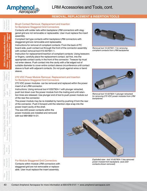
270 VDC Power <strong>Module</strong> Removal, Replacement and Insertion<br />
for Backplane Staggered Grid Connectors<br />
270 VDC power modules can be removed and replaced within the power<br />
insert of an <strong>LRM</strong> connector.<br />
Instructions: Using removal tool #10507924-1 with plunger retracted,<br />
push tool down over the power module from the mating end until retention<br />
tines are released. Use plunger end of tool to push power module out<br />
of the rear the connector.<br />
The power module may be re-installed by hand by pushing it from the rear<br />
of the connector. Push it forward until the retention clips snap into the<br />
power insert cavity of the shell.<br />
The size 22D power contacts within the<br />
power modules are installed and removed<br />
with tool M81969/14-01.<br />
Removal tool 10-507941-1 for removing<br />
compliant contacts from <strong>LRM</strong> backplanes<br />
Removal tool 10-507924-1 (plunger retracted)<br />
for removing 270 VDC power modules from <strong>LRM</strong><br />
backplanes<br />
LMD/LMS<br />
Rectangular<br />
Interconnects<br />
Other<br />
Rectangular<br />
Interconnects<br />
Rack & Panel<br />
Brush<br />
Ruggedized<br />
For <strong>Module</strong> Staggered Grid Connectors:<br />
Contacts within module <strong>LRM</strong> connectors with<br />
staggered grid are not removable or replaceable.<br />
User must replace the insert assembly.<br />
Exploded view - tool 10-507924-1 has removed<br />
power module from backplane. (size 22D<br />
contacts shown removed)<br />
40<br />
Contact <strong>Amphenol</strong> <strong>Aerospace</strong> for more information at 800-678-0141 • www.amphenol-aerospace.com


