Engineering Recommendation For Using OCV Kits For School Busses
Engineering Recommendation For Using OCV Kits For School Busses
Engineering Recommendation For Using OCV Kits For School Busses

You also want an ePaper? Increase the reach of your titles
YUMPU automatically turns print PDFs into web optimized ePapers that Google loves.
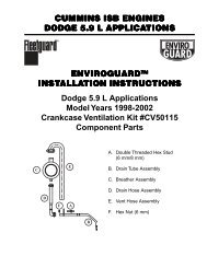
Installation Instructions<br />
<strong>Engineering</strong> <strong>Recommendation</strong> <strong>For</strong> <strong>Using</strong><br />
<strong>OCV</strong> <strong>Kits</strong> <strong>For</strong> <strong>School</strong> <strong>Busses</strong><br />
The recommendations will be made for two types of Cummins engines:<br />
1. <strong>Busses</strong> fitted with Cummins ISB 5.9L engine (engines manufactured from<br />
1998-2002)<br />
2. <strong>Busses</strong> fitted with Cummins B series and/or mechanical engines<br />
<strong>Busses</strong> fitted with Cummins ISB 5.9L engine<br />
(engines manufactured from 1998-2002)<br />
Figure 1: As seen in the above picture the newer ISB engines have a factory breather<br />
assembly located on the left side of the front wall of the engine, just behind the fan<br />
Use the new Dodge Ram Kit, CV 50115. This kit along with the installation<br />
instructions should have all the components and hoses that will be required to<br />
change the factory fitted breather with the Fleetguard Enviroguard <strong>OCV</strong> breather.
<strong>Busses</strong> fitted with Cummins B series and/or mechanical engines<br />
Use the Crankcase Ventilation Kit, CV 50106 and the mounting bracket<br />
#393814000S. The recommended modifications are:<br />
Figure 2: This mechanical Cummins engine breathes from a location that is on the rear left<br />
side wall of the engine under the rockerbox, as approximately shown by the yellow oval<br />
It is recommended that the <strong>OCV</strong> breather should be installed on the front right<br />
side of the engine compartment as shown in the figure below:<br />
Figure 3: The physical location of the Fleetguard Enviroguard <strong>OCV</strong> breather in the engine<br />
compartment
The mounting bracket #393814000S (optional with the Kit CV50106) should be<br />
used for installing the <strong>OCV</strong> breather to the wall of the engine compartment as<br />
shown in Figure 3 above. This bracket is supplied as a flat component and it<br />
should be bent approximately 1.5” from the top two <strong>OCV</strong> breather mounting hole<br />
locations as shown in the Figure 4.<br />
Figure 4: The estimated 1.5" from the top two <strong>OCV</strong> breather mounting hole locations to<br />
where the flat bracket should be bent at 90°<br />
The vent line on the left rear corner of the engine should be attached to the new<br />
¾” vent line (a 5/8” to ¾” adapter is included in the kit if needed). This hose<br />
should be routed along the wall of the engine compartment to the <strong>OCV</strong> breather.<br />
It is highly recommended that the hose be shielded from the hot areas around<br />
the exhaust manifold on the right side of the engine. A metal tube could be an<br />
alternative to using rubber hose along this area.
Figure 5: The route for the vent hose from the engine wall on the left rear of the engine to<br />
the front right engine compartment wall where the <strong>OCV</strong> breather should be installed<br />
The orange lines on the above figure signify areas where the vent hose/tube<br />
should be shielded from the hot areas of the engine to avoid overheating of the<br />
rubber hose. IF THE VENT HOSE/TUBE IS LESS THAN 4” FROM THE<br />
EXHAUST MAINFOLD, ONLY A METAL TUBE SHOULD BE USED,<br />
OTHERWISE FOR DISTANCES MORE THAN 4” CAREFULLY SHIELD THE<br />
RUBBER HOSE IN THE HEAT INTENSE REGIONS.<br />
Connect the drain line from the <strong>OCV</strong> breather to the engine oil pan as shown in<br />
the INSTALLATION INSTRUCTION booklet provided with the kit.<br />
Caution: There should at least be a 14” vertical clearance between the breather assembly<br />
and the drain port into the engine oil pan. Do not install the drain line hose to the engine<br />
oil pan so that there is an oil trap along the path (make sure that it does not go up and<br />
down along the way). Make sure that the provided check valve is always in the vertical<br />
position.<br />
LT32528<br />
©2004 Fleetguard Inc.<br />
Printed in the U.S.A.<br />
<strong>For</strong> more information, contact Customer Assistance at<br />
1-800-22-FILTER (1-800-223-4583), fax 1-800-999-8664,<br />
or visit us at www.fleetguard.com.