Create successful ePaper yourself
Turn your PDF publications into a flip-book with our unique Google optimized e-Paper software.
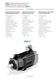
<strong>HS6E</strong><br />
Subminiature Interlock Switches with Solenoid<br />
<strong>HS6B</strong><br />
Subminiature Interlock Switches<br />
(07/03/16)
5-pole<br />
Subminiature Interlock Switches<br />
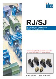
Thinnest Body in Its Class<br />
75<br />
15<br />
Thin Body<br />
75<br />
Actual Size (mm)<br />
Energy saving<br />
276 mA<br />
Approx. 40%<br />
(compared with<br />
previous models)<br />
110 mA<br />
Space saving design with<br />
angled connection cable<br />
<strong>HS6E</strong><br />
Minimum Radius<br />
30 mm<br />
Angled<br />
connection<br />
cable<br />
Minimum Radius<br />
30 mm<br />
Space Saving<br />
(Approx. 30 mm)<br />
HS5E<br />
Miniature Interlock<br />
Switch with Solenoid<br />
<strong>HS6E</strong><br />
Subminiature Interlock<br />
Switch with Solenoid<br />
Power Consumption by Solenoid + Indicator<br />
RoHS directive compliant (2002/95/EC)<br />
The <strong>HS6E</strong> series subminiature interlock switches with solenoid do<br />
not contain lead, cadmium, mercury, hexavalent chromium, PBB,<br />
or PBDE.<br />
2<br />
(07/03/16)
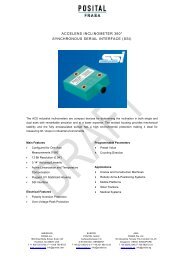
Virtually Limitless Mounting Options<br />
Sliding Doors<br />
Top Mounting<br />
<strong>HS6E</strong><br />
Top Mounting<br />
Actuator<br />
Left-opening<br />
Right-opening<br />
Front Mounting<br />
Front Mounting<br />
Left-opening<br />
Right-opening<br />
Hinged Doors<br />
Top Mounting<br />
Side Mounting<br />
Left-opening<br />
Right-opening<br />
Left-opening<br />
Right-opening<br />
Side Mounting<br />
Bottom Mounting<br />
Up-opening<br />
Up-opening<br />
(07/03/16)<br />
3
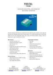
Manual Unlocking Possible<br />
from Three Directions<br />
The actuator can be unlocked manually with<br />
manual unlocks on either sides of the switch body,<br />
or by depressing a plate.<br />
For details, see page 14.<br />
When unlocking with manual unlocks<br />
Make a key access hole in the wall for<br />
manual unlocking.<br />
Manual Unlocking Key<br />
When the switch is installed inside a<br />
machine, the actuator can be unlocked<br />
with the manual unlocking key by<br />
making a key access hole in the wall.<br />
Optically enhanced lens<br />
provides for wide viewing<br />
angle for power indicator.<br />
Wide viewing angle (approx. 120°)<br />
Solenoid Power Indicator<br />
(Green LED)<br />
Mounting Surface<br />
4<br />
(07/03/16)
Features - <strong>HS6E</strong> and <strong>HS6B</strong> Subminiature Interlock Switches<br />
• <strong>HS6E</strong>: with solenoid, <strong>HS6B</strong>: without solenoid<br />
• Common mounting holes - <strong>HS6E</strong> and <strong>HS6B</strong><br />
• Common actuators - <strong>HS6E</strong> and <strong>HS6B</strong><br />
Dimensions<br />
<strong>HS6E</strong><br />
(with solenoid)<br />
<strong>HS6B</strong><br />
(without solenoid)<br />
75<br />
15<br />
30<br />
15<br />
75<br />
78<br />
Mounting Hole Layout<br />
• Add one additional hole in the mounting panel for the <strong>HS6B</strong>, then the <strong>HS6E</strong> can be installed on the same panel.<br />
<strong>HS6E</strong><br />
(with solenoid)<br />
<strong>HS6B</strong><br />
(without solenoid)<br />
30<br />
50.8<br />
50.8<br />
<strong>HS6E</strong><br />
28.5<br />
1<br />
20 1<br />
1 20 1<br />
All dimensions in mm.<br />
Common Actuators<br />
• The same actuators can be used on the <strong>HS6E</strong> and <strong>HS6B</strong>.<br />
Vertical/Horizontal Angle Adjustable<br />
<strong>HS6E</strong><br />
HS9Z-A66<br />
HS9Z-A65<br />
<strong>HS6B</strong><br />
HS9Z-A61<br />
HS9Z-A62<br />
HS9Z-A62S<br />
Straight Right-angle Right-angle with Plate<br />
(07/03/16)<br />
5
<strong>HS6E</strong> Subminiature Interlock Switches with Solenoid<br />
Small interlock switch with five poles and solenoid.<br />
Ideal for applications in tight spaces.<br />
• Compact body: 75 × 15 × 75 mm<br />
15-mm-wide, thinnest solenoid type interlock switch in the world.<br />
• Reversible mounting and angled cable allow four actuator insertion<br />
directions.<br />
• Energy saving. 24V DC, 110 mA (solenoid: 100 mA, LED: 10 mA)<br />
• Manual unlocking possible on three sides.<br />
• RoHS compliant<br />
• LED indicator shows solenoid operation<br />
Spring Lock Type<br />
• Automatically locks the actuator without power applied to the solenoid.<br />
• After the machine stops, unlocking is completed by the solenoid.<br />
• Manual unlocking is possible on three sides in the event of power<br />
failure or maintenance.<br />
Solenoid Lock Type<br />
• The actuator is locked when energized.<br />
• The actuator is unlocked when de-energized.<br />
• Flexible locking function can be achieved, for an application where<br />
locking is not required and sudden stopping of a machine must be<br />
prevented.<br />
Ratings<br />
• Contact Ratings<br />
300V (door monitor contact)<br />
150V (lock monitor contact)<br />
Rated Insulation Voltage (Ui) (Note 1)<br />
30V (between LED or solenoid and<br />
ground)<br />
Operating temperature –25 to 35°C<br />
2.5A (up to 2 circuits)<br />
1.0A (3 or more circuits)<br />
Rated Thermal Current (Ith)<br />
Operating temperature 35 to 50°C<br />
1.0A (1 circuit)<br />
0.5A (2 or more circuits)<br />
Rated Voltage (Ue) 30V 125V 250V<br />
Rated Current (Ie) ∗<br />
Main & Lock<br />
Monitor Circuits<br />
Door Monitor<br />
Circuit<br />
AC<br />
DC<br />
AC<br />
DC<br />
• Minimum applicable load (reference value): 3V AC/DC, 5 mA<br />
• UL, c-UL rating<br />
Main/Lock monitor circuit: 125V AC, 1A Pilot duty<br />
125V DC, 0.22A Pilot duty<br />
Door monitor circuit:<br />
240V AC, 0.75A Pilot duty<br />
250V DC, 0.27A Pilot duty<br />
• TÜV rating<br />
Main/Lock monitor circuit: AC-15 125V/1A, DC-13 125V/0.22A<br />
Door monitor circuit: AC-15 240V/0.75A, DC-13 250V/0.27A<br />
• Solenoid/Indicator<br />
Resistive load (AC-12) — 2A —<br />
Inductive Load (AC-15) — 1A —<br />
Resistive load (DC-12) 2A 0.4A —<br />
Inductive Load (DC-13) 1A 0.22A —<br />
Resistive load (AC-12) — 2.5A 1.5A<br />
Inductive Load (AC-15) — 1.5A 0.75A<br />
Resistive load (DC-12) 2.5A 1.1A 0.55A<br />
Inductive Load (DC-13) 2.3A 0.55A 0.27A<br />
Locking Mechanism Spring Lock Type Solenoid Lock Type<br />
Rated Voltage<br />
24V DC<br />
Rated Current<br />
110 mA (solenoid 100 mA, LED 10 mA)<br />
(initial value)<br />
Coil Resistance<br />
240Ω (at 20°C)<br />
Pickup Voltage<br />
Rated voltage × 85% maximum (at 20°C)<br />
Dropout Voltage<br />
Rated voltage × 10% minimum (at 20°C)<br />
Maximum Continuous<br />
Applicable Voltage<br />
Rated voltage × 110%<br />
Maximum Continuous<br />
Applicable Time<br />
Continuous<br />
Solenoid<br />
Indicator<br />
Insulation Class<br />
Light Source<br />
Illumination Color<br />
Class F<br />
LED<br />
Green<br />
• Horizontal/Vertical Angle Adjustable Actuators<br />
• Straight Actuator<br />
(SUS304)<br />
Specifications<br />
• Right-angle Actuator (SUS304)<br />
UL 508 (UL listed)<br />
CSA C22.2, No. 14 (c-UL listed)<br />
ISO 14119<br />
IEC 60947-5-1<br />
Applicable Standards EN 60947-5-1 (TÜV approval)<br />
EN 1088 (TÜV approval)<br />
GS-ET-19<br />
IEC 60204-1/EN 60204-1 (applicable standards for use)<br />
Operating<br />
–25 to +50°C (no freezing)<br />
Temperature<br />
Relative Humidity 45 to 85% (no condensation)<br />
Storage Temperature –40 to +80°C (no freezing)<br />
Pollution Degree 3<br />
Impulse Withstand<br />
Voltage<br />
Insulation Resistance<br />
(500V DC megger)<br />
Contact Resistance<br />
Main & lock monitor circuits: 1.5 KV<br />
Door monitor circuit: 2.5 kV<br />
Between solenoid/LED and ground: 0.5 kV<br />
Between live and dead metal parts: 100 MΩ minimum<br />
Between terminals of different poles: 100 MΩ minimum<br />
300 mΩ maximum (initial value, 1m cable)<br />
500 mΩ maximum (initial value, 3m cable)<br />
700 mΩ maximum (initial value, 5m cable)<br />
Electric Shock<br />
Protection<br />
Class II (IEC 61140)<br />
Degree of Protection IP67 (IEC 60529)<br />
Shock Resistance<br />
Operating extremes: 100 m/s 2 (10G)<br />
Damage limits: 1000 m/s 2 (100G)<br />
Operating extremes:<br />
Vibration Resistance<br />
10 to 55 Hz, amplitude 0.35 mm<br />
Damage limits: 30 Hz, amplitude 1.5 mm<br />
Actuator Operating<br />
Speed<br />
0.05 to 1.0 m/s<br />
Direct Opening Travel 8.0 mm minimum<br />
Direct Opening Force 60N minimum<br />
Actuator Retention<br />
Force<br />
500N minimum (GS-ET-19)<br />
Operating Frequency 900 operations/h<br />
Mechanical Durability 1,000,000 operations minimum (GS-ET-19)<br />
100,000 operations minimum (rated load)<br />
Electrical Durability 1,000,000 operations minimum (24V AC/DC, 100 mA)<br />
(operating frequency 900 operations/h)<br />
Conditional<br />
Short-circuit Current<br />
Cable<br />
Cable Diameter<br />
Weight (approx.)<br />
50A (250V)<br />
(Use 250V/10A fast-blow fuse for short-circuit protection.)<br />
UL2464, No. 22 AWG<br />
(12-core: 0.3 mm 2 or equivalent/core)<br />
ø7.6 mm<br />
200g (<strong>HS6E</strong>-∗∗∗01)<br />
6<br />
(07/03/16)
Types<br />
• Subminiature Interlock Switch<br />
<strong>HS6E</strong> Subminiature Interlock Switches with Solenoid<br />
Lock Mechanism Circuit Number Contact Arrangement Cable Length Type No.<br />
(When inserted) (When OFF)<br />
1m <strong>HS6E</strong>-L44B01-G<br />
(+) (–)<br />
A2 A1<br />
L<br />
Main Circuit: 1NC+1NC, Monitor Circuit: 2NC/1NO<br />
3m <strong>HS6E</strong>-L44B03-G<br />
Main Circuit: 11 12 41 42<br />
Monitor Circuit: 21 22 53 54<br />
Monitor Circuit: 31 32<br />
5m <strong>HS6E</strong>-L44B05-G<br />
Main Circuit: 1NC+1NC, Monitor Circuit: 2NC/1NC<br />
1m <strong>HS6E</strong>-M44B01-G<br />
Spring Lock<br />
M<br />
Main Circuit:<br />
Monitor Circuit:<br />
Monitor Circuit:<br />
11<br />
21<br />
31<br />
12<br />
22<br />
32<br />
41 42<br />
51 52<br />
3m<br />
5m<br />
<strong>HS6E</strong>-M44B03-G<br />
<strong>HS6E</strong>-M44B05-G<br />
Main Circuit: 1NC+1NC, Monitor Circuit: 1NC, 1NO/1NO<br />
1m<br />
<strong>HS6E</strong>-N44B01-G<br />
N<br />
Main Circuit: 11 12 41 42<br />
Monitor Circuit: 21 22 53 54<br />
Monitor Circuit: 33 34<br />
3m<br />
5m<br />
<strong>HS6E</strong>-N44B03-G<br />
<strong>HS6E</strong>-N44B05-G<br />
Main Circuit: 1NC+1NC, Monitor Circuit: 1NC, 1NO/1NC<br />
1m<br />
<strong>HS6E</strong>-P44B01-G<br />
P<br />
Main Circuit:<br />
Monitor Circuit:<br />
Monitor Circuit:<br />
11 12 41 42<br />
21 22 51 52<br />
33 34<br />
3m<br />
5m<br />
<strong>HS6E</strong>-P44B03-G<br />
<strong>HS6E</strong>-P44B05-G<br />
L<br />
(When inserted) (When ON)<br />
(+) (–)<br />
A2 A1<br />
Main Circuit: 1NC+1NC, Monitor Circuit: 2NC/1NO<br />
1m<br />
3m<br />
<strong>HS6E</strong>-L7Y4B01-G<br />
<strong>HS6E</strong>-L7Y4B03-G<br />
Main Circuit:<br />
Monitor Circuit:<br />
Monitor Circuit:<br />
11 12<br />
21 22<br />
31 32<br />
41 42<br />
53 54<br />
5m<br />
<strong>HS6E</strong>-L7Y4B05-G<br />
Main Circuit: 1NC+1NC, Monitor Circuit: 2NC/1NC<br />
1m<br />
<strong>HS6E</strong>-M7Y4B01-G<br />
Solenoid Lock<br />
M<br />
Main Circuit:<br />
Monitor Circuit:<br />
Monitor Circuit:<br />
11<br />
21<br />
31<br />
12<br />
22<br />
32<br />
41 42<br />
51 52<br />
3m<br />
5m<br />
<strong>HS6E</strong>-M7Y4B03-G<br />
<strong>HS6E</strong>-M7Y4B05-G<br />
Main Circuit: 1NC+1NC, Monitor Circuit: 1NC, 1NO/1NO<br />
1m<br />
<strong>HS6E</strong>-N7Y4B01-G<br />
N<br />
Main Circuit: 11 12 41 42<br />
Monitor Circuit: 21 22 53 54<br />
Monitor Circuit: 33 34<br />
3m<br />
5m<br />
<strong>HS6E</strong>-N7Y4B03-G<br />
<strong>HS6E</strong>-N7Y4B05-G<br />
Main Circuit: 1NC+1NC, Monitor Circuit: 1NC, 1NO/1NC<br />
1m<br />
<strong>HS6E</strong>-P7Y4B01-G<br />
P<br />
Main Circuit:<br />
Monitor Circuit:<br />
Monitor Circuit:<br />
11 12 41 42<br />
21 22 51 52<br />
33 34<br />
3m<br />
5m<br />
<strong>HS6E</strong>-P7Y4B03-G<br />
<strong>HS6E</strong>-P7Y4B05-G<br />
• The contact arrangements show the contact status when the actuator is inserted and locked.<br />
• LED color is G (green) only.<br />
• Actuators are not supplied with the interlock switch and must be ordered separately.<br />
(07/03/16)<br />
7
<strong>HS6E</strong> Subminiature Interlock Switches with Solenoid<br />
• Actuator<br />
Appearance Ordering Type No. Remarks<br />
Straight Actuator<br />
HS9Z-A61<br />
The tensile strength of HS9Z-A61 actuator is 500N maximum.<br />
Do no apply excessive load, otherwise the actuator may fall off the door.<br />
Right-angle Actuator<br />
Right-angle Actuator with Mounting Plate<br />
HS9Z-A62<br />
HS9Z-A62S<br />
The tensile strength of HS9Z-A62 actuator is 100N maximum.<br />
Do no apply excessive load, otherwise the actuator may fall off the door.<br />
When tensile strength of 100N or more is required, use the HS9Z-A62S<br />
actuator.<br />
The tensile strength of HS9Z-A62S actuator is 500N maximum.<br />
Do no apply excessive load, otherwise the actuator may fall off the door.<br />
Angle Adjustable Actuator<br />
Angle Adjustable Actuator<br />
HS9Z-A65<br />
HS9Z-A66<br />
The HS9Z-A65 and HS9Z-A66 have the metal key installed in opposite<br />
directions. Select actuator by determining the required moving direction<br />
in consideration of the door and interlock switch.<br />
See pages 10, 13, and 14.<br />
The tensile strength of HS9Z-A65 and HS9Z-A66 actuators is 500N<br />
maximum.<br />
Type No. Development<br />
Circuit Code<br />
Main Circuit Door Monitor<br />
Circuit<br />
Lock Monitor<br />
Circuit<br />
L: 1NC+1NC 2NC 1NO<br />
M: 1NC+1NC 2NC 1NC<br />
N: 1NC+1NC 1NC, 1NO 1NO<br />
P: 1NC+1NC 1NC, 1NO 1NC<br />
Solenoid Unit Voltage/Lock Mechanism<br />
4: 24V DC/Spring Lock<br />
7Y: 24V DC/Solenoid Lock<br />
<strong>HS6E</strong> - L 4 4 B 05 -G<br />
LED Color<br />
G: green<br />
Cable Length<br />
01: 1m<br />
03: 3m<br />
05: 5m<br />
Housing Color<br />
B: Black<br />
Pilot Light Voltage<br />
4: 24V DC<br />
8<br />
(07/03/16)
<strong>HS6E</strong> Subminiature Interlock Switches with Solenoid<br />
Dimensions<br />
• Interlock Switch<br />
• Mounting Hole Layout<br />
10.1<br />
5.5<br />
Hole for Manual Unlocking<br />
ø12 (reference)<br />
3-M4 Screw<br />
(ø4.3 or M4 tapped hole)<br />
(12.6 ±1 )<br />
(5)<br />
(14)<br />
22.6 ±1<br />
22.6 ±1 (14)<br />
(6.2)<br />
(25)<br />
0.8<br />
50.8<br />
0.8<br />
(42) (Note)<br />
0.8<br />
48.8<br />
Actuator Stop<br />
(supplied)<br />
Actuator Stop<br />
(supplied)<br />
Actuator Stop<br />
(supplied)<br />
Interlock Switch<br />
Actuator Stop<br />
Door Stop<br />
0.8<br />
4<br />
30<br />
20.5<br />
15<br />
4<br />
10.4<br />
37<br />
15<br />
46.1<br />
41.8<br />
ø4.4<br />
28.5<br />
(22.5) (22.5)<br />
28.5<br />
75<br />
35<br />
30<br />
20.5<br />
(2.3)<br />
C12<br />
R2.1<br />
4<br />
4<br />
Manual Unlocking Key<br />
41.8<br />
20 to 22<br />
3-M4 Screw Hole for Manual Unlocking<br />
(ø4.3 or M4 tapped hole)<br />
ø12 (reference)<br />
1 20<br />
1<br />
20.5<br />
30<br />
28.5<br />
20 to 22<br />
41.8<br />
When using straight actuator<br />
(HS9Z-A61)<br />
When using right-angle actuator<br />
(HS9Z-A62S)<br />
When using horizontal/vertical<br />
angle adjustable actuator<br />
(HS9Z-A65/A66)<br />
Note: 41.4 when using HS9Z-A62.<br />
The tensile strength of the HS9Z-A62 actuator is<br />
100N. When tensile force exceeding 100N is<br />
expected, use the HS9Z-A62S actuator, which<br />
has a mounting plate.<br />
• Actuator Mounting Reference Position<br />
As shown in the figure on the right, the mounting reference position of the actuator<br />
when inserted in the interlock switch is:<br />
The actuator stop on the actuator lightly touches the interlock switch.<br />
Note: After mounting the actuator, remove the actuator stop from the actuator.<br />
Door Stop<br />
HS9Z-A61 Actuator<br />
(07/03/16)<br />
9
<strong>HS6E</strong> Subminiature Interlock Switches with Solenoid<br />
Actuator Dimensions<br />
Straight Actuator (HS9Z-A61)<br />
20.9<br />
(15.8)<br />
43.2<br />
Right-angle Actuator (HS9Z-A62)<br />
The tensile strength of the HS9Z-A62 actuator is<br />
100N. When tensile force exceeding 100N is<br />
expected, use the HS9Z-A62S actuator.<br />
Right-angle Actuator (HS9Z-A62S)<br />
Note: See page 15 for actuator installation.<br />
When mounted (33.8)<br />
When<br />
mounted (5) 14<br />
2-ø4.3<br />
1.2<br />
14 15 0.8<br />
10.4<br />
8.4<br />
3.5<br />
When mounted (33.8)<br />
When<br />
mounted (5.6) 0.8<br />
8.4<br />
When mounted (6.2)<br />
0.8<br />
8.4<br />
When mounted (10.2)<br />
When mounted (6.2)<br />
14<br />
2-ø9<br />
Rubber Bushing<br />
Note 1<br />
Actuator Stop (supplied)<br />
ø2-9<br />
When mounted (5)<br />
1.2<br />
Rubber Bushing<br />
3.5<br />
2-ø4.3<br />
14<br />
14<br />
13.1<br />
34<br />
2-ø9<br />
Rubber Bushing<br />
1.2<br />
Mounting Plate (supplied)<br />
3.5<br />
2-ø4.2<br />
13.1 14<br />
41.1<br />
(Note) Actuator Stop (supplied)<br />
(Note) Actuator Stop (supplied)<br />
Note: The actuator stop is used to adjust the actuator position. Remove the actuator stop after the actuator position is mounted.<br />
Angle Adjustable Actuator<br />
(HS9Z-A65)<br />
Horizontal Adjustment<br />
Orienting Insert<br />
0.8<br />
Angle Adjustable Actuator<br />
(HS9Z-A66)<br />
The HS9Z-A65 and HS9Z-A66<br />
have the metal key inserted in<br />
opposite directions.<br />
Actuator Adjustment<br />
Orientation<br />
The orientation of actuator adjustment<br />
(horizontal/vertical) can be changed<br />
using the orienting insert (white plastic)<br />
installed on the back of the actuator.<br />
3.5<br />
1.2<br />
Horizontal Adjustment<br />
Angle Adjustment<br />
(M3 Hexagon Socket Head Screw)<br />
Orienting Insert<br />
20°<br />
20°<br />
Horizontal Adjustment<br />
Vertical Adjustment<br />
Vertical Adjustment<br />
Orienting Insert<br />
13<br />
Angle Adjustment<br />
(M3 Hexagon Socket Head Screw)<br />
28.2<br />
7.5<br />
2<br />
5.5<br />
16.8<br />
Vertical Adjustment<br />
Angle Adjustment<br />
(M3 Hexagon Socket Head Screw)<br />
(Note 1)<br />
Actuator Stop (Supplied)<br />
20°<br />
34<br />
15<br />
2.5<br />
(Note)<br />
Actuator Stop (supplied)<br />
Angle Adjustment<br />
(M3 Hexagon Socket<br />
Head Screw)<br />
R2.1<br />
(M4 Holes)<br />
Note: The base is made of glass-reinforced PA66 (66 nylon). Angle adjustment screws are stainless steel.<br />
When using adhesive on screws, take material compatibility into consideration.<br />
25<br />
20°<br />
Actuator Mounting Hole Layout<br />
(horizontal/vertical swing)<br />
25<br />
2-M4 Screw<br />
(ø4.3 or M4 tapping screw)<br />
Accessory<br />
Description<br />
Manual Unlock Key (long type)<br />
Ordering Type No.<br />
HS9Z-T3<br />
Manual Unlock Key<br />
(supplied) (plastic)<br />
Manual Unlock Key<br />
(long type) (metal)<br />
(24)<br />
15<br />
9<br />
ø4<br />
ø10<br />
3<br />
18<br />
(24.5)<br />
6.5<br />
15<br />
130<br />
4<br />
All dimensions in mm.<br />
10<br />
(07/03/16)
<strong>HS6E</strong> Subminiature Interlock Switches with Solenoid<br />
Circuit Diagrams and Operating Characteristics<br />
• Spring Lock Type<br />
Interlock Switch Status<br />
Status 1 Status 2 Status 3 Status 4<br />
• Door closed<br />
• Machine ready to<br />
operate<br />
• Solenoid<br />
de-energized<br />
• Door closed<br />
• Machine cannot be<br />
operated<br />
• Solenoid<br />
energized<br />
• Door open<br />
• Machine cannot be<br />
operated<br />
• Solenoid<br />
energized<br />
• Door open<br />
• Machine cannot be<br />
operated<br />
• Solenoid<br />
de-energized<br />
Unlocking using<br />
Manual Unlock Key<br />
• Door closed<br />
• Machine cannot be<br />
operated<br />
• Solenoid<br />
de-energized<br />
Door Status<br />
UNLOCK<br />
Circuit Diagram (Example: <strong>HS6E</strong>-N4)<br />
Door Closed (locked) Closed (unlocked) Open Open Closed (unlocked)<br />
<strong>HS6E</strong>-L4<br />
Main Circuit:<br />
Monitor Circuit:<br />
Monitor Circuit:<br />
<strong>HS6E</strong>-M4<br />
Door Lock<br />
Monitor Monitor<br />
(+) (–)<br />
A2 A1<br />
11 12 41 42<br />
21 22 53 54<br />
31 32<br />
Main Circuit 11-42 ON (closed) OFF (open) OFF (open) OFF (open) OFF (open)<br />
Door Monitor Circuit<br />
(door closed) 21-22<br />
Door Monitor Circuit<br />
(door closed) 31-32<br />
Lock Monitor Circuit<br />
(unlocked) 53-54<br />
11<br />
21<br />
33<br />
12<br />
(+)<br />
A2<br />
41<br />
22 53<br />
34<br />
(–)<br />
A1<br />
42<br />
54<br />
(+)<br />
A2<br />
(–)<br />
A1<br />
11 12 41 42<br />
21 22 53 54<br />
33 34<br />
ON (closed) ON (closed) OFF (open) OFF (open) ON (closed)<br />
ON (closed) ON (closed) OFF (open) OFF (open) ON (closed)<br />
OFF (open) ON (closed) ON (closed) ON (closed) ON (closed)<br />
Main Circuit 11-42 ON (closed) OFF (open) OFF (open) OFF (open) OFF (open)<br />
11<br />
21<br />
33<br />
12<br />
(+)<br />
A2<br />
41<br />
22 53<br />
34<br />
(–)<br />
A1<br />
42<br />
54<br />
11<br />
21<br />
33<br />
12<br />
22<br />
34<br />
(+)<br />
A2<br />
LOCK<br />
Manually<br />
Unlocked<br />
41<br />
53<br />
(–)<br />
A1<br />
42<br />
54<br />
Type No. and Circuit Diagram<br />
Main Circuit:<br />
Monitor Circuit:<br />
Monitor Circuit:<br />
<strong>HS6E</strong>-N4<br />
Main Circuit:<br />
Monitor Circuit:<br />
Monitor Circuit:<br />
11 12 41 42<br />
21 22 51 52<br />
31 32<br />
11 12 41 42<br />
21 22 53 54<br />
33 34<br />
Door Monitor Circuit<br />
(door closed) 21-22<br />
Door Monitor Circuit<br />
(door closed) 31-32<br />
Lock Monitor Circuit<br />
(locked) 51-52<br />
ON (closed) ON (closed) OFF (open) OFF (open) ON (closed)<br />
ON (closed) ON (closed) OFF (open) OFF (open) ON (closed)<br />
ON (closed) OFF (open) OFF (open) OFF (open) OFF (open)<br />
Main Circuit 11-42 ON (closed) OFF (open) OFF (open) OFF (open) OFF (open)<br />
Door Monitor Circuit<br />
(door closed) 21-22<br />
Door Monitor Circuit<br />
(door open) 33-34<br />
ON (closed) ON (closed) OFF (open) OFF (open) ON (closed)<br />
OFF (open) OFF (open) ON (closed) ON (closed) OFF (open)<br />
Lock Monitor Circuit<br />
(unlocked) 53-54<br />
OFF (open) ON (closed) ON (closed) ON (closed) ON (closed)<br />
<strong>HS6E</strong>-P4<br />
Main Circuit 11-42 ON (closed) OFF (open) OFF (open) OFF (open) OFF (open)<br />
Main Circuit:<br />
Monitor Circuit:<br />
Monitor Circuit:<br />
11 12 41 42<br />
21 22 51 52<br />
33 34<br />
Door Monitor Circuit<br />
(door closed) 21-22<br />
Door Monitor Circuit<br />
(door open) 33-34<br />
ON (closed) ON (closed) OFF (open) OFF (open) ON (closed)<br />
OFF (open) OFF (open) ON (closed) ON (closed) OFF (open)<br />
Lock Monitor Circuit<br />
(locked) 51-52<br />
ON (closed) OFF (open) OFF (open) OFF (open) OFF (open)<br />
Solenoid Power A1-A2 (all types) OFF (de-energized) ON (energized) ON (energized) OFF (de-energized) OFF (de-energized)<br />
Main circuit: Connected to the control circuit of machine drive part, sending the interlock signals of the protective door.<br />
Monitor circuit: Sends the monitoring signals of open/closed and lock/unlocked statuses of the protective door.<br />
Operation Characteristics (reference)<br />
Main Circuit<br />
Door Monitor Circuit (door open, NO)<br />
Door Monitor Circuit (door closed, NC)<br />
Lock Monitor Circuit (unlocked, NO)<br />
Lock Monitor Circuit (locked, NC)<br />
0 (Actuator Insertion Position)<br />
1.1 (Locked Position)<br />
4.7 5.0 27.4 (stroke in mm)<br />
: Contacts ON (closed)<br />
: Contacts OFF (open)<br />
• The characteristics shown in the chart above are of the HS9Z-A61, -A62, -A65, and -A66 actuators.<br />
For HS9Z-A62S actuator, subtract 0.6 mm.<br />
• The characteristics show the contact status when the actuator enters an entry slot of an interlock switch.<br />
(07/03/16)<br />
11
<strong>HS6E</strong> Subminiature Interlock Switches with Solenoid<br />
• Solenoid Lock Type<br />
Interlock Switch Status<br />
Status 1 Status 2 Status 3 Status 4<br />
• Door closed<br />
• Machine ready to<br />
operate<br />
• Solenoid<br />
energized<br />
• Door closed<br />
• Machine cannot be<br />
operated<br />
• Solenoid<br />
de-energized<br />
• Door open<br />
• Machine cannot be<br />
operated<br />
• Solenoid<br />
de-energized<br />
• Door open<br />
• Machine cannot be<br />
operated<br />
• Solenoid<br />
energized<br />
Unlocking using<br />
Manual Unlock Key<br />
• Door closed<br />
• Machine cannot be<br />
operated<br />
• Solenoid<br />
de-energized<br />
Door Status<br />
UNLOCK<br />
LOCK<br />
Manually<br />
Unlocked<br />
Circuit Diagram (Example: <strong>HS6E</strong>-N7Y)<br />
Door Closed (locked) Closed (unlocked) Open Open Closed (unlocked)<br />
<strong>HS6E</strong>-L7Y<br />
Main Circuit:<br />
Monitor Circuit:<br />
Monitor Circuit:<br />
<strong>HS6E</strong>-M7Y<br />
Door Lock<br />
Monitor Monitor<br />
(+) (–)<br />
A2 A1<br />
11 12 41 42<br />
21 22 53 54<br />
31 32<br />
Main Circuit 11-42 ON (closed) OFF (open) OFF (open) OFF (open) OFF (open)<br />
Door Monitor Circuit<br />
(door closed) 21-22<br />
Door Monitor Circuit<br />
(door closed) 31-32<br />
Lock Monitor Circuit<br />
(unlocked) 53-54<br />
11<br />
21<br />
33<br />
12<br />
(+)<br />
A2<br />
41<br />
22 53<br />
34<br />
(–)<br />
A1<br />
42<br />
54<br />
(+)<br />
A2<br />
(–)<br />
A1<br />
11 12 41 42<br />
21 22 53 54<br />
33 34<br />
ON (closed) ON (closed) OFF (open) OFF (open) ON (closed)<br />
ON (closed) ON (closed) OFF (open) OFF (open) ON (closed)<br />
OFF (open) ON (closed) ON (closed) ON (closed) ON (closed)<br />
Main Circuit 11-42 ON (closed) OFF (open) OFF (open) OFF (open) OFF (open)<br />
11<br />
21<br />
33<br />
12<br />
(+)<br />
A2<br />
41<br />
22 53<br />
34<br />
(–)<br />
A1<br />
42<br />
54<br />
11<br />
21<br />
33<br />
12<br />
22<br />
34<br />
(+)<br />
A2<br />
41<br />
53<br />
(–)<br />
A1<br />
42<br />
54<br />
Type No. and Circuit Diagram<br />
Main Circuit: 11 12 41 42<br />
Monitor Circuit: 21 22 51 52<br />
Monitor Circuit: 31 32<br />
<strong>HS6E</strong>-N7Y<br />
Main Circuit: 11 12 41 42<br />
Monitor Circuit: 21 22 53 54<br />
Monitor Circuit: 33 34<br />
Door Monitor Circuit<br />
(door closed) 21-22<br />
Door Monitor Circuit<br />
(door closed) 31-32<br />
Lock Monitor Circuit<br />
(locked) 51-52<br />
ON (closed) ON (closed) OFF (open) OFF (open) ON (closed)<br />
ON (closed) ON (closed) OFF (open) OFF (open) ON (closed)<br />
ON (closed) OFF (open) OFF (open) OFF (open) OFF (open)<br />
Main Circuit 11-42 ON (closed) OFF (open) OFF (open) OFF (open) OFF (open)<br />
Door Monitor Circuit<br />
(door closed) 21-22<br />
Door Monitor Circuit<br />
(door open) 33-34<br />
ON (closed) ON (closed) OFF (open) OFF (open) ON (closed)<br />
OFF (open) OFF (open) ON (closed) ON (closed) OFF (open)<br />
Lock Monitor Circuit<br />
(unlocked) 53-54<br />
OFF (open) ON (closed) ON (closed) ON (closed) ON (closed)<br />
<strong>HS6E</strong>-P7Y<br />
Main Circuit 11-42 ON (closed) OFF (open) OFF (open) OFF (open) OFF (open)<br />
Main Circuit:<br />
Monitor Circuit:<br />
Monitor Circuit:<br />
11 12 41 42<br />
21 22 51 52<br />
33 34<br />
Door Monitor Circuit<br />
(door closed) 21-22<br />
Door Monitor Circuit<br />
(door open) 33-34<br />
ON (closed) ON (closed) OFF (open) OFF (open) ON (closed)<br />
OFF (open) OFF (open) ON (closed) ON (closed) OFF (open)<br />
Lock Monitor Circuit<br />
(locked) 51-52<br />
ON (closed) OFF (open) OFF (open) OFF (open) OFF (open)<br />
Solenoid Power A1-A2 (all types) ON (energized) OFF (de-energized) OFF (de-energized)<br />
Main circuit: Connected to the control circuit of machine drive part, sending the interlock signals of the protective door.<br />
Monitor circuit: Sends the monitoring signals of open/closed and lock/unlocked statuses of the protective door.<br />
Note 1: Do not attempt manual unlocking while the solenoid is energized.<br />
Note 2: Do not energize the solenoid for a long period of time while the door is open or while the door is unlocked manually using the manual unlock key.<br />
Operation Characteristics (reference)<br />
Main Circuit<br />
Door Monitor Circuit (door open, NO)<br />
Door Monitor Circuit (door closed, NC)<br />
Lock Monitor Circuit (unlocked, NO)<br />
Lock Monitor Circuit (locked, NC)<br />
0 (Actuator Insertion Position)<br />
1.1 (Locked Position)<br />
4.7 5.0 27.4 (stroke in mm)<br />
: Contacts ON (closed)<br />
: Contacts OFF (open)<br />
• The characteristics shown in the chart above are of the HS9Z-A61, -A62, -A65, and -A66 actuators.<br />
For HS9Z-A62S actuator, subtract 0.6 mm.<br />
• The characteristics show the contact status when the actuator enters an entry slot of an interlock switch.<br />
ON (energized)<br />
(Note 2)<br />
OFF (de-energized)<br />
to ON (re-energized)<br />
(Note 1) (Note 2)<br />
12<br />
(07/03/16)
<strong>HS6E</strong> Subminiature Interlock Switches with Solenoid<br />
Safety Precautions<br />
• In order to avoid electric shock or fire, turn power off before<br />
installation, removal, wiring, maintenance, or inspection of<br />
the interlock switch.<br />
• If relays are used in the circuit between the interlock switch<br />
and the load, use only safety relays, since welded or sticking<br />
contacts of standard relays may invalidate the functions<br />
of the interlock switch. Perform a risk assessment and<br />
make a safety circuit which satisfies the requirements of<br />
the safety category.<br />
• Do not place a PLC in the circuit between the interlock<br />
switch and the load. Safety security can be endangered in<br />
the event of a malfunction of the PLC.<br />
• Do not disassemble or modify the interlock switch, otherwise<br />
a malfunction or an accident may occur.<br />
• Do not install the actuator in a location where a human<br />
body may come in contact. Otherwise injury may occur.<br />
• Solenoid lock type is locked when energized, and unlocked<br />
when de-energized. When energization is interrupted due<br />
to wire disconnection or other failures, the interlock switch<br />
may be unlocked causing possible danger to the operators.<br />
Solenoid lock type must not be used in applications where<br />
locking is strictly required for safety. Perform a risk assessment<br />
and determine whether solenoid lock type is appropriate.<br />
Instructions<br />
• Regardless of door types, do not use the interlock switch<br />
as a door stop. Install a mechanical door stop at the end of<br />
the door to protect the interlock switch against excessive<br />
force.<br />
• Do not apply external force on the actuator while<br />
unlocking, otherwise the actuator may not be unlocked.<br />
• Do not apply excessive shock to the interlock switch when<br />
opening or closing the door. A shock to the interlock switch<br />
exceeding 1,000 m/s 2 may cause damage to the interlock<br />
switch.<br />
• If the operating atmosphere is contaminated, use a<br />
protective cover to prevent the entry of foreign objects into<br />
the interlock switch through the actuator entry slots.<br />
• Entry of a considerable amount of foreign objects into the<br />
interlock switch may affect the mechanism of the interlock<br />
switch and cause a malfunction.<br />
• Do not store the interlock switches in a dusty, humid, or<br />
organic-gas atmosphere, or in an area subjected to direct<br />
sunlight.<br />
• Use proprietary actuators only. When other actuators are<br />
used, the interlock switch may be damaged.<br />
• The locking strength is rated at 500N. Do not apply a load<br />
higher than the rated value. When a higher load is<br />
expected, provide an additional system consisting of<br />
another interlock switch without lock (such as the <strong>HS6B</strong>/<br />
HS7A interlock switch) or a sensor to detect door opening<br />
and stop the machine.<br />
• Regardless of door types, do not use the interlock switch<br />
as a door lock. Install a separate lock using a latch or other<br />
measures.<br />
• While the solenoid is energized, the switch temperature<br />
rises approximately 35°C above the ambient temperature<br />
(to approximately 85°C while the ambient temperature is<br />
50°C). Do not touch to prevent burns. If cables come into<br />
contact with the switch, use heat-resistant cables.<br />
• Bouncing will occur on the lock monitor contact during<br />
locking and unlocking (reference value: 20 ms).<br />
• Although the HS9Z-A61/A62/A62S actuators alleviate<br />
shock when the actuator enters a slot in the interlock<br />
switch, make sure that excessive shock is not applied.<br />
If the rubber bushings become deformed or cracked,<br />
replace with new ones.<br />
Minimum Radius of Hinged Door<br />
• When using the interlock switch on hinged doors, refer to<br />
the minimum radius of doors shown below. When using on<br />
doors with small minimum radius, use the angle adjustable<br />
actuator (HS9Z-A65 and HS9Z-A66).<br />
Note: Because deviation or dislocation of hinged doors may occur<br />
in actual applications, make sure of the correct operation<br />
before installation.<br />
When using the HS9Z-A62/A62S Right-angle Actuator<br />
• When the door hinge is on the extension line of the interlock switch<br />
surface:<br />
Minimum Radius<br />
160 mm<br />
Door Hinge<br />
Minimum Radius<br />
160 mm<br />
Door Hinge<br />
• When the door hinge is on the extension line of the interlock switch<br />
surface:<br />
Minimum Radius<br />
230 mm<br />
Door Hinge<br />
Minimum Radius<br />
230 mm<br />
Door Hinge<br />
(07/03/16)<br />
13
<strong>HS6E</strong> Subminiature Interlock Switches with Solenoid<br />
When using the HS9Z-A65/HS9Z-A66 Angle Adjustable<br />
Actuator<br />
• When the door hinge is on the extension line of the interlock<br />
switch surface<br />
Horizontal Adjustment<br />
HS9Z-A65<br />
HS9Z-A66<br />
Minimum<br />
Radius<br />
50 mm<br />
50 mm<br />
Minimum<br />
Radius<br />
• When the door hinge is on the extension line of the actuator<br />
mounting surface<br />
Horizontal Adjustment<br />
HS9Z-A65<br />
HS9Z-A66<br />
70 mm<br />
70 mm<br />
Minimum Radius<br />
Minimum<br />
Radius<br />
Door Hinge<br />
Door Hinge<br />
Door Hinge<br />
Door Hinge<br />
Actuator Angle Adjustment for the HS9Z-A65/HS9Z-A66<br />
• Using the angle adjustment screw, the actuator angle can be<br />
adjusted (see figures on page 10).<br />
Adjustable angle: 0 to 20°<br />
• The larger the adjusted angle of the actuator, the smaller the<br />
applicable radius of the door opening.<br />
• After installing the actuator, open the door. Then adjust the<br />
actuator so that its edge can enter properly into the actuator<br />
entry slot of the interlock switch.<br />
• After adjusting the actuator angle, apply Loctite to the<br />
adjustment screw so that the screw will not become loose.<br />
Mounting Examples<br />
Application on Sliding Doors<br />
Door<br />
Vertical Adjustment<br />
HS9Z-A65<br />
HS9Z-A66<br />
HS9Z-A65<br />
HS9Z-A66<br />
HS9Z-A61 Actuator<br />
Minimum<br />
Radius<br />
50 mm<br />
50 mm<br />
Minimum<br />
Radius<br />
Vertical Adjustment<br />
70mm<br />
70mm<br />
Minimum Radius<br />
Minimum<br />
Radius<br />
Door Hinge<br />
Label<br />
Door Hinge<br />
Door Hinge<br />
Label<br />
Door Hinge<br />
Application on Hinged Doors<br />
HS9Z-A62S Actuator<br />
For Manual Unlocking<br />
Spring lock type<br />
The <strong>HS6E</strong> allows manual unlocking of the actuator to pre-check<br />
proper door operation before wiring or turning power on, as well as<br />
for emergency use such as a power failure.<br />
Solenoid lock type<br />
The <strong>HS6E</strong> can be unlocked manually in emergency.<br />
When using the manual unlock key<br />
UNLOCK<br />
LOCK<br />
Manual Unlocking<br />
(installed on both sides)<br />
Normal Position<br />
Manual Unlocking<br />
Position<br />
• When locking or unlocking the interlock switch manually, turn<br />
the key fully using the manual unlocking key supplied with the<br />
switch.<br />
• Using the interlock switch with the key not fully turned (less<br />
than 90°) may cause damage to the switch or operation<br />
failures (when manually unlocked, the switch will keep the<br />
main circuit disconnected and the door unlocked).<br />
• Do not apply excessive force (0.45 N·m or more) to the<br />
manual unlock part, otherwise the manual unlock part will<br />
become damaged.<br />
• Do not leave the manual unlocking key attached to the switch<br />
during operation. This is dangerous because the switch can<br />
always be unlocked while the machine is in operation.<br />
Manual Unlock Key<br />
(supplied with the switch)<br />
When unlocking pushing the plate inside the interlock switch<br />
• Remove the screw at the side of the interlock switch (the same<br />
side where actuator is inserted) and insert a small screwdriver.<br />
• Push the plate inside the interlock switch toward the LED<br />
indicator using the screwdriver until the actuator is unlocked.<br />
• Tighten the screw to a proper torque (0.3 to 0.5 N·m). Do not<br />
tighten with excessive force, otherwise the interlock switch will<br />
be damaged. Be sure to reinstall the screw, otherwise the<br />
waterproof capability will be lost.<br />
<strong>HS6E</strong><br />
Interlock Switch<br />
Latch<br />
Door Stop<br />
Note: When mounting an actuator, make sure<br />
that the actuator enters the slot in the<br />
correct direction, as shown on the right.<br />
Screwdriver<br />
Caution<br />
Before manually unlocking the interlock switch, make sure<br />
that the machine has come to a complete stop. Manual<br />
unlocking during operation may unlock the interlock switch<br />
before the machine stops, and the function of the interlock<br />
switch with solenoid is lost. While the solenoid is energized,<br />
do not unlock the switch manually (solenoid lock type).<br />
14<br />
(07/03/16)
<strong>HS6E</strong> Subminiature Interlock Switches with Solenoid<br />
Recommended Tightening Torque of<br />
Mounting Screws<br />
• Interlock switch: 1.0 to 1.5 N·m (three M4 screws)<br />
• Actuators: 1.0 to 1.5 N·m (two M4 screws)<br />
• The above recommended tightening torques of the mounting<br />
screws are the values with hex socket head bolts. When other<br />
screws are used and tightened to a smaller torque, make sure<br />
that the screws do not become loose after mounting.<br />
• Mounting bolts are not supplied with the interlock and must be<br />
supplied by the user.<br />
• To avoid unauthorized or unintended removal of the interlock<br />
switch and the actuator, it is recommended that the interlock<br />
switch and the actuator are installed in an unremovable<br />
manner, for example using special screws, rivets, or welding<br />
the screws.<br />
• When installing the HS9Z-A62S actuator, use the mounting<br />
plate (supplied with the actuator) on the hinged door, and<br />
secure the actuator tightly using two M4 screws.<br />
• The mounting plate has orientation.<br />
• Do not lose the mounting plate.<br />
M4 Screws<br />
Mounting Plate (supplied)<br />
Wire Identification<br />
• Wires can be identified by the color and or a white line printed<br />
on the wire.<br />
No. Insulation Color No. Insulation Color<br />
1 Blue/White 7 White<br />
2 Gray 8 Black<br />
3 Pink 9 Pink/White<br />
4 Orange 10 Brown/White<br />
5 Orange/White 11 Brown<br />
6 Gray/White 12 Blue<br />
Note: Wires of gray or gray/white are not used and should not be connected.<br />
11<br />
12<br />
1 4<br />
10<br />
3 2 5<br />
9 6<br />
8 7<br />
Colored Insulation<br />
Jacket<br />
Terminal Number Identification<br />
• When wiring, identify the terminal number of each contact by<br />
the color of insulation.<br />
• The following table shows the identification of terminal<br />
numbers.<br />
• When wiring, cut unused wires at the end of the jacket to avoid<br />
incorrect wiring.<br />
Rubber Bushing<br />
Type<br />
Contact Arrangement<br />
Door Monitor<br />
Lock Monitor<br />
Hinged Door<br />
M4 Tapped Hole<br />
<strong>HS6E</strong>-L<br />
(+) (–)<br />
White A2 A1 Black<br />
Cables<br />
• Do not fasten or loosen the gland at the bottom of the interlock<br />
switch.<br />
• When bending the cable during wiring, make sure that the<br />
cable radius is kept at 30 mm minimum.<br />
• When wiring, make sure that water or oil does not enter from<br />
the end of the cable.<br />
• Do not open the lid of the interlock switch. Otherwise the<br />
interlock switch will be damaged.<br />
• The solenoid has polarity. Make sure of the correct polarity<br />
when wiring.<br />
<strong>HS6E</strong>-M<br />
<strong>HS6E</strong>-N<br />
<strong>HS6E</strong>-P<br />
Main circuit: Blue<br />
Monitor circuit: Brown<br />
Monitor circuit: Orange<br />
Main circuit: Blue<br />
Monitor circuit: Brown<br />
Monitor circuit: Orange<br />
Main circuit: Blue<br />
Monitor circuit: Brown<br />
Monitor circuit: Orange<br />
Main circuit: Blue<br />
Monitor circuit: Brown<br />
Monitor circuit: Orange<br />
11 12<br />
41 42<br />
21 22 Brown/White Pink 53 54<br />
31 32 Orange/White<br />
11<br />
21<br />
31<br />
12<br />
41 42<br />
22 Brown/White Pink 51 52<br />
32 Orange/White<br />
11 12 41 42<br />
21 22 Brown/White Pink 53 54<br />
33 34 Orange/White<br />
11 12 41 42<br />
21 22 Brown/White Pink 51 52<br />
33 34 Orange/White<br />
Blue/White<br />
Pink/White<br />
Blue/White<br />
Pink/White<br />
Blue/White<br />
Pink/White<br />
Blue/White<br />
Pink/White<br />
Note: The contact arrangements show the contact status when the actuator<br />
is inserted and locked.<br />
Gland<br />
Minimum Radius<br />
30 mm<br />
(70)<br />
Minimum<br />
Radius<br />
30 mm<br />
(50)<br />
Gland<br />
(07/03/16)<br />
15
<strong>HS6B</strong> Subminiature Interlock Switches<br />
World-class compactness with three poles of contacts.<br />
• World’s smallest switch: 30 × 30 × 78 mm<br />
• Dual contacts and monitor contacts achieve the highest safety<br />
category (ISO 13849-1, EN 954-1)<br />
• Two actuator entry slots provide flexibility for installation options.<br />
• Integral cable design minimizes wiring, preventing wiring<br />
mistakes.<br />
• Can be mounted in two directions.<br />
• Degree of protection (contacts): IP67 (IEC 60529)<br />
Housing allows drainage.<br />
• NC contacts are direct opening action (IEC/EN 60947-5-1).<br />
• Proprietary actuators prevent unauthorized opening of the<br />
contacts (ISO14119, EN1088).<br />
• Vertical/horizontal Angle<br />
Adjustable Actuator (for<br />
hinged door)<br />
• Right-angle Actuator<br />
(SUS304)<br />
• Straight Actuator<br />
(SUS304)<br />
Direct<br />
Opening<br />
Action<br />
Double<br />
Insulation<br />
Types<br />
Contact Configuration Cable Length<br />
Type No.<br />
(Package quantity: 1)<br />
1NC-1NO 1m <strong>HS6B</strong>-11B01<br />
Zb<br />
11<br />
12<br />
3m<br />
<strong>HS6B</strong>-11B03<br />
33<br />
34<br />
5m<br />
<strong>HS6B</strong>-11B05<br />
2NC 1m <strong>HS6B</strong>-02B01<br />
Zb<br />
11<br />
12<br />
3m<br />
<strong>HS6B</strong>-02B03<br />
31<br />
32<br />
5m<br />
<strong>HS6B</strong>-02B05<br />
2NC-1NO 1m <strong>HS6B</strong>-12B01<br />
Zb<br />
11<br />
12<br />
3m<br />
<strong>HS6B</strong>-12B03<br />
21<br />
22<br />
31<br />
32<br />
5m<br />
<strong>HS6B</strong>-12B05<br />
3NC<br />
Zb<br />
1m <strong>HS6B</strong>-03B01<br />
11<br />
12<br />
3m<br />
<strong>HS6B</strong>-03B03<br />
21<br />
22<br />
31<br />
32<br />
5m<br />
<strong>HS6B</strong>-03B05<br />
Actuators<br />
Description<br />
Straight<br />
Right-angle<br />
Horizontal/vertical Angle Adjustable<br />
(for hinged doors) (Note)<br />
Note: Select an actuator that moves in the direction required by the<br />
hinged door and interlock switch (see pages 17 and 18).<br />
Contact Ratings<br />
Type No.<br />
(Package quantity: 1)<br />
HS9Z-A61<br />
HS9Z-A62<br />
HS9Z-A65<br />
HS9Z-A66<br />
Rated Insulation Voltage (Ui)<br />
300V<br />
Rated Current (Ith) 2.5A<br />
Rated Voltage (Ue) ∗ 30V 125V 250V<br />
Resistive load (AC-12) — 2.5A 1.5A<br />
AC<br />
Rated Inductive Load (AC-15) — 1.5A 0.75A<br />
Current<br />
(Ie) ∗ Resistive load (DC-12) 2.5A 1.1A 0.55A<br />
DC<br />
Inductive Load (DC-13) 2.3A 0.55A 0.27A<br />
• Minimum applicable load (reference): 3V AC/DC, 5mA<br />
∗ Ratings approved by safety agencies<br />
C300: AC-15, 0.75A/240V<br />
Q300: DC-13, 0.27A/250V<br />
Specifications<br />
UL508 (UL listed)<br />
CSA C22.2, No. 14 (c-UL listed)<br />
ISO 14119<br />
EN 1088<br />
Applicable Standards IEC 60947-5-1<br />
EN 60947-5-1 (DEMKO approval)<br />
GS-ET-15 (BG approval)<br />
IEC 60204-1/ EN 60204-1<br />
(applicable standards for use)<br />
Applicable Directive 73/23/EEC (Low Voltage Directive)<br />
Operating<br />
–25 to +70°C (no freezing)<br />
Temperature<br />
Relative Humidity 45 to 85% (no condensation)<br />
Storage Temperature –40 to +80°C (no freezing)<br />
Pollution Degree 3<br />
Impulse Withstand<br />
4 kV<br />
Voltage<br />
Insulation Resistance<br />
(500V DC megger)<br />
Contact Resistance<br />
Between live and dead metal parts:<br />
100 MΩ minimum<br />
Between terminals of different poles:<br />
100 MΩ minimum<br />
300 mΩ maximum (initial value, 1m cable)<br />
500 mΩ maximum (initial value, 3m cable)<br />
700 mΩ maximum (initial value, 5m cable)<br />
Electric Shock<br />
Protection Class<br />
Class II (IEC 61140)<br />
Degree of Protection IP67 (IEC 60529)<br />
Shock Resistance<br />
Operating extremes: 300 m/s 2 (30G)<br />
Damage limits: 1000 m/s 2 (100G)<br />
Operating extremes:<br />
Vibration Resistance<br />
5 to 55 Hz, amplitude 0.5 mm<br />
Damage limits:<br />
30 Hz, amplitude 1.5 mm<br />
Actuator Operating<br />
Speed<br />
0.05 to 1.0 m/s<br />
Direct Opening Travel 8 mm minimum<br />
Direct Opening Force 60N minimum<br />
Operating Frequency 1200 operations/h<br />
Mechanical Durability 1,000,000 operations minimum (GS-ET-15)<br />
100,000 operations minimum<br />
Electrical Durability (operating frequency 1200 operations/h,<br />
load AC-12 250V/1.5A, DC-12 250V/0.2A)<br />
Conditional<br />
Short-circuit Current<br />
Housing Color<br />
Cable<br />
Weight (approx.)<br />
50A (250V) (Use 250V/10A fast-blow fuse for shortcircuit<br />
protection.)<br />
Black<br />
UL2464 No. 20 AWG (6-core)<br />
120g (<strong>HS6B</strong>-03B01)<br />
16<br />
(07/03/16)
<strong>HS6B</strong> Subminiature Interlock Switches<br />
Dimensions<br />
• Interlock Switch<br />
10.4<br />
1<br />
R2.2<br />
(58)<br />
• Mounting Hole Layout<br />
20 to 22<br />
10.1<br />
Slot Plug (Note 1)<br />
(supplied)<br />
15<br />
5.5<br />
30<br />
20<br />
1<br />
5.5<br />
35<br />
78<br />
4<br />
(9)<br />
2-M4 Screws<br />
(ø4.3 or M4 tapped)<br />
The interlock switch can be<br />
mounted in two directions.<br />
Note 1: Plug the unused actuator<br />
entry slot using the slot plug<br />
supplied with the interlock switch.<br />
10.4<br />
27.6<br />
4<br />
(ø7.6)<br />
• Using the HS9Z-A61 Straight Actuator • Using the HS9Z-A62 Right-angle Actuator • Using the HS9Z-A65/A66<br />
Angle Adjustable Actuator<br />
(12.6 ±1 )<br />
(25)<br />
(21.4)<br />
30.8<br />
(5)<br />
28.8 22.6 ±1<br />
0.8<br />
22.6 ±1<br />
0.8<br />
(14)<br />
(5)<br />
(14)<br />
(30.1 ±1 )<br />
Actuator Stop<br />
(Note 2)<br />
(supplied)<br />
0.8<br />
50.8<br />
40.1 ±1<br />
Actuator Stop<br />
(Note 2) (supplied)<br />
0.8<br />
0.8<br />
(41.4)<br />
±1 (25)<br />
15.1<br />
Actuator Stop<br />
(Note 2) (supplied)<br />
0.8<br />
48.8<br />
Actuator Dimensions<br />
• Straight Actuaor (HS9Z-A61)<br />
2-ø4.3<br />
14<br />
20.9 43.2<br />
(15.8)<br />
14 15 0.8<br />
8.4<br />
• Angle Adjustmentable Actuator (HS9Z-A65)<br />
Horizontal Adjustment<br />
Orienting Insert<br />
0.8<br />
3.5<br />
1.2<br />
• Angle Adjustmentable Actuator<br />
(HS9Z-A66)<br />
The HS9Z-A65 and HS9Z-A66 have the<br />
metal key inserted in opposite directions.<br />
Horizontal Adjustment<br />
Angle Adjustment<br />
(M3 Hexagon Socket Head Screw)<br />
20°<br />
When<br />
mounted (5)<br />
2-ø9<br />
1.2<br />
Rubber Bushing<br />
10.4<br />
• Right-angle Actuator (HS9Z-A62)<br />
When mounted (33.8)<br />
When<br />
mounted (5.6) 0.8<br />
8.4<br />
3.5<br />
Actuator Stop (supplied)<br />
(Note 2)<br />
Vertical Adjustment<br />
13<br />
Orienting Insert<br />
34<br />
15<br />
2.5<br />
Angle Adjustment<br />
(M3 Hexagon Socket Head Screw)<br />
7.5<br />
28.2<br />
2<br />
Angle Adjustment<br />
(M3 Hexagon<br />
Socket Head Screw)<br />
20°<br />
5.5<br />
16.8<br />
R2.1<br />
(M4 Holes)<br />
25<br />
Vertical Adjustment<br />
20°<br />
Angle Adjustment<br />
(M3 Hexagon Socket Head Screw)<br />
Actuator Stop (supplied)<br />
(Note 2)<br />
20°<br />
Orienting Insert<br />
2-ø9<br />
When mounted (5)<br />
Rubber<br />
Bushing<br />
1.2<br />
3.5<br />
2-ø4.3<br />
14<br />
Actuator Stop (supplied)<br />
(Note 2)<br />
14<br />
13.1<br />
34<br />
The orientation of actuator adjustment (horizontal/vertical) can be<br />
changed using the orienting insert (white plastic) installed on the<br />
back of the actuator.<br />
The base is made of glass-reinforced PA66 (66 nylon).<br />
Angle adjustment screws are stainless steel. When using adhesive<br />
on screws, take material compatibility into consideration.<br />
Note 2: After mounting the actuator, remove the actuator<br />
stop from the interlock switch.<br />
Horizontal Adjustment<br />
Vertical Adjustment<br />
• Actuator Mounting Hole Layout<br />
14<br />
Straight/Right-angle<br />
Actuator<br />
2-M4 Screws<br />
(ø4.3 or M4 tapped)<br />
Angle Adjustable Actuator<br />
25<br />
2-M4 Screws<br />
(ø4.3 or M4 tapped)<br />
(07/03/16)<br />
17
<strong>HS6B</strong> Subminiature Interlock Switches<br />
Contact Configuration and Operation Chart<br />
Type<br />
<strong>HS6B</strong>-11<br />
<strong>HS6B</strong>-02<br />
<strong>HS6B</strong>-12<br />
<strong>HS6B</strong>-03<br />
1NC-1NO<br />
2NC<br />
2NC-1NO<br />
3NC<br />
Contact Configuration<br />
11<br />
33<br />
11<br />
31<br />
11<br />
21<br />
33<br />
11<br />
21<br />
31<br />
Zb<br />
Zb<br />
Zb<br />
Zb<br />
12<br />
34<br />
12<br />
32<br />
12<br />
22<br />
34<br />
12<br />
22<br />
32<br />
11-12<br />
33-34<br />
11-12<br />
31-32<br />
11-12<br />
21-22<br />
33-34<br />
11-12<br />
21-22<br />
31-32<br />
Actuator inserted completely<br />
Contact Operation Chart<br />
0.8 (Actuator Mounting Reference Position)<br />
0 5.5 5.8 28.2 (Travel: mm)<br />
Actuator removed completely<br />
: Contact ON (closed)<br />
: Contact OFF (open)<br />
Minimum Radius of Hinged Door<br />
• When using the interlock switch on hinged doors, refer to the<br />
minimum radius of doors shown below. When using on doors<br />
with small minimum radius, use the angle adjustable actuator<br />
(HS9Z-A65 and HS9Z-A66).<br />
Note: Because deviation or dislocation of hinged doors may occur<br />
in actual applications, make sure of the correct operation<br />
before installation.<br />
When using the HS9Z-A62 Right-angle Actuator<br />
• When the door hinge is on the extension line of the interlock switch<br />
surface:<br />
When using the HS9Z-A65/HS9Z-A66 Angle Adjustable<br />
Actuator<br />
• When the door hinge is on the extension line of the interlock switch<br />
surface:<br />
Horizontal Adjustment<br />
HS9Z-A65<br />
HS9Z-A66<br />
50 mm<br />
Minimum Radius<br />
Door Hinge<br />
Label<br />
Vertical Adjustment<br />
HS9Z-A65<br />
HS9Z-A66<br />
50 mm<br />
Minimum Radius<br />
Door Hinge<br />
Label<br />
50 mm<br />
Minimum Radius<br />
Door Hinge<br />
50 mm<br />
Minimum Radius<br />
Door Hinge<br />
• When the door hinge is on the extension line of the actuator<br />
mounting surface<br />
160 mm<br />
Minimum Radius<br />
Door Hinge<br />
160 mm<br />
Minimum Radius<br />
Door Hinge<br />
Horizontal Adjustment<br />
70 mm<br />
Minimum Radius<br />
Door Hinge<br />
Vertical Adjustment<br />
70 mm<br />
Minimum Radius<br />
Door Hinge<br />
Label<br />
Label<br />
• When the door hinged is on the extension line of the actuator<br />
mounting surface:<br />
HS9Z-A65<br />
HS9Z-A66<br />
HS9Z-A65<br />
HS9Z-A66<br />
70 mm<br />
Minimum Radius<br />
Door Hinge<br />
70 mm<br />
Minimum Radius<br />
Door Hinge<br />
230 mm<br />
Minimum Radius<br />
Door Hinge<br />
230 mm<br />
Minimum Radius<br />
Door Hinge<br />
Actuator Angle Adjustment for the HS9Z-A65/HS9Z-A66<br />
• Using the angle adjustment screw, the actuator angle can be<br />
adjusted (see figures on page 17).<br />
Adjustable angle: 0 to 20°<br />
• The larger the adjusted angle of the actuator, the smaller the<br />
applicable radius of the door opening.<br />
• After installing the actuator, open the door. Then adjust the<br />
actuator so that its edge can enter properly into the actuator<br />
entry slot of the interlock switch.<br />
• After adjusting the actuator angle, apply Loctite to the<br />
adjustment screw so that the screw will not become loose.<br />
18<br />
(07/03/16)
<strong>HS6B</strong> Subminiature Interlock Switches<br />
Safety Precautions<br />
• In order to avoid electric shock or fire, turn the power off before<br />
installation, removal, wiring, maintenance, or inspection of the<br />
switch.<br />
• If relays are used in the circuit between the interlock switch<br />
and the load, use only safety relays, since welded or sticking<br />
contacts of standard relays may invalidate the functions of the<br />
interlock switch. Perform a risk assessment and make a safety<br />
circuit which satisfies the requirements of the safety category.<br />
• Do not place a PLC in the circuit between the interlock switch<br />
and the load. Safety security can be endangered in the event<br />
of a malfunction of the PLC.<br />
• Do not disassemble or modify the interlock switch, otherwise a<br />
malfunction or an accident may occur.<br />
• Do not install the actuator in the location where a human body<br />
may come in contact. Otherwise injury may occur.<br />
Instructions<br />
• Regardless of door types, do not use the interlock switch as a<br />
door stop. Install a mechanical door stop at the end of the door<br />
to protect the interlock switch against excessive force.<br />
• Do not apply excessive shock to the interlock switch when<br />
opening or closing the door. A shock to the interlock switch<br />
exceeding 1,000 m/s 2 may cause damage to the interlock<br />
switch.<br />
• If the operating atmosphere is contaminated, use a protective<br />
cover to prevent the entry of foreign objects into the interlock<br />
switch through the actuator entry slots.<br />
• Entry of a considerable amount of foreign objects into the<br />
interlock switch may affect the mechanism of the interlock<br />
switch and cause a malfunction.<br />
• Do not store the interlock switches in a dusty, humid, or<br />
organic-gas atmosphere.<br />
• Use proprietary actuators only. When other actuators are<br />
used, the interlock switch may be damaged.<br />
• Cover the unused actuator entry slot using the slot plug<br />
supplied with the interlock switch.<br />
Mounting<br />
Mount the interlock switch on the<br />
machine. Mount the actuator on the<br />
hinged door.<br />
Note: When mounting an actuator, make sure<br />
that the actuator enters into the slot in<br />
the correct direction, as shown on the<br />
right.<br />
Recommended Screw Tightening Torque<br />
• Interlock switch (M4 screw): 1.0 to 1.5 N·m<br />
• Actuator (M4 screw): 1.0 to 1.5 N·m<br />
• Mounting bolts are not supplied, and must be purchased<br />
separately by the user.<br />
Note: The above recommended tightening torque of the mounting<br />
screw is the value with hex socket head bolts. When other<br />
screws are used and tightened to a smaller torque, make<br />
sure that the screws do not become loose after mounting.<br />
Cable<br />
• Do not fasten or loosen the gland at the bottom of the interlock<br />
switch.<br />
• When bending cable during wiring, make sure that the cable<br />
radius is kept at 40 mm minimum.<br />
• When wiring, make sure that water or<br />
oil does not enter from the end of<br />
cable.<br />
Gland<br />
Minimum<br />
Radius<br />
40 mm<br />
(100)<br />
Wire Identification<br />
• Wires can be identified by color and/or a white line printed on<br />
the wire.<br />
No.<br />
Insulation<br />
Color<br />
No.<br />
Insulation<br />
Color<br />
1 Orange/White 4 Brown<br />
2 Blue/White 5 Blue<br />
3 Brown/White 6 Orange<br />
Colored Insulation<br />
Jacket<br />
Dummy Insulation<br />
(black)<br />
Terminal Number Identification<br />
• When wiring, the terminal number on each contact can be<br />
identified by wire color.<br />
• The following diagrams show a safety (main) contact and one<br />
or two auxiliary contacts for two-contact and three-contact<br />
types.<br />
Blue 11<br />
Orange 33<br />
Blue 11<br />
Brown 21<br />
Orange 33<br />
1NC-1NO<br />
Zb<br />
2NC-1NO<br />
Zb<br />
12 Blue/White Blue 11<br />
34 Orange/White Orange 31<br />
12 Blue/White<br />
22 Brown/White<br />
34 Orange/White<br />
Blue 11<br />
Brown 21<br />
Orange 31<br />
2NC<br />
Zb<br />
3NC<br />
Zb<br />
12 Blue/White<br />
32 Orange/White<br />
12 Blue/White<br />
22 Brown/White<br />
32 Orange/White<br />
• When wiring, cut any dummy insulation (black) and any<br />
unused wires at the end of the jacket to avoid incorrect wiring.<br />
(07/03/16)<br />
19
HS5E Series Miniature Interlock Switches with Solenoid<br />
Solenoid interlock switch with four contacts in a compact body.<br />
Ideal for small or special-shape doors with limited mounting<br />
space.<br />
• Compact body. 35 × 40 × 146 mm.<br />
• Four poles with gold-plated contacts.<br />
• Spring lock and solenoid lock types are available.<br />
• The head orientation can be rotated, allowing for 8 different actuator<br />
entries.<br />
• Metal head ensures durability.<br />
• Locking strength 1000N minimum (GS-ET-19)<br />
• Integrated cable design minimizes wiring, preventing incorrect wiring.<br />
• RoHS directive compliant.<br />
BG standard in Germany<br />
Direct Opening Double<br />
Action Insulation<br />
HS5B Series Miniature Interlock Switches<br />
Metal head type and M20 conduit port newly added.<br />
• Actuators are interchangeable with the HS5E miniature interlock switches<br />
with solenoid.<br />
• Actuators with rubber bushing available.<br />
• RoHS directive compliant.<br />
• The head orientation can be rotated, allowing for 8 different actuator<br />
entries.<br />
• Compact body. 30 × 30 × 90 mm.<br />
BG standard in Germany<br />
Direct Opening Double<br />
Action Insulation<br />
Specifications and other descriptions in this catalog are subject to change without notice.<br />
7-31, Nishi-Miyahara 1-Chome, Yodogawa-ku, Osaka 532-8550, Japan<br />
Tel: +81-6-6398-2571, Fax: +81-6-6392-9731<br />
E-mail: products@idec.co.jp<br />
www.idec.com<br />
IDEC CORPORATION (USA)<br />
1175 Elko Drive, Sunnyvale, CA 94089-2209, USA<br />
Tel: +1-408-747-0550 / (800) 262-IDEC (4332)<br />
Fax: +1-408-744-9055 / (800) 635-6246<br />
E-mail: opencontact@idec.com<br />
IDEC CANADA LIMITED<br />
Unit 22-151, Brunel Road, Mississauga, Ontario,<br />
L4Z 1X3, Canada<br />
Tel: +1-905-890-8561, Toll Free: (888) 317-4332<br />
Fax: +1-905-890-8562<br />
E-mail: sales@ca.idec.com<br />
IDEC AUSTRALIA PTY. LTD.<br />
2/3 Macro Court, Rowville, Victoria 3178, Australia<br />
Tel: +61-3-9763-3244, Toll Free: 1800-68-4332<br />
Fax: +61-3-9763-3255<br />
E-mail: sales@au.idec.com<br />
IDEC ELECTRONICS LIMITED<br />
Unit 2, Beechwood, Chineham Business Park,<br />
Basingstoke, Hampshire RG24 8WA, UK<br />
Tel: +44-1256-321000, Fax: +44-1256-327755<br />
E-mail: sales@uk.idec.com<br />
IDEC ELEKTROTECHNIK GmbH<br />
Wendenstrasse 331, 20537 Hamburg, Germany<br />
Tel: +49-40-25 30 54 - 0, Fax: +49-40-25 30 54 - 24<br />
E-mail: service@idec.de<br />
IDEC (SHANGHAI) CORPORATION<br />
Room 608-609, 6F, Gangtai Plaza, No. 700,<br />
Yan'an East Road, Shanghai 200001, PRC<br />
Tel: +86-21-5353-1000, Fax: +86-21-5353-1263<br />
E-mail: idec@cn.idec.com<br />
IDEC (BEIJING) CORPORATION<br />
Room 211B, Tower B, The Grand Pacific Building,<br />
8A Guanghua Road, Chaoyang District,<br />
Beijing 100026, PRC<br />
Tel: +86-10-6581-6131, Fax: +86-10-6581-5119<br />
IDEC (SHENZHEN) CORPORATION<br />
Unit AB-3B2, Tian Xiang Building, Tian’an Cyber Park,<br />
Fu Tian District, Shenzhen, Guang Dong 518040, PRC<br />
Tel: +86-755-8356-2977, Fax: +86-755-8356-2944<br />
IDEC IZUMI (H.K.) CO., LTD.<br />
Unit 1505-07, DCH Commercial Centre No. 25,<br />
Westlands Road, Quarry Bay, Hong Kong<br />
Tel: +852-2803-8989, Fax: +852-2565-0171<br />
E-mail: info@hk.idec.com<br />
IDEC TAIWAN CORPORATION<br />
8F-1, No. 79, Hsin Tai Wu Road, Sec. 1,<br />
Hsi-Chih, Taipei County, Taiwan<br />
Tel: +886-2-2698-3929, Fax: +886-2-2698-3931<br />
E-mail: service@tw.idec.com<br />
IDEC IZUMI ASIA PTE. LTD.<br />
No. 31, Tannery Lane #05-01, Dragon Land<br />
Building, Singapore 347788<br />
Tel: +65-6746-1155, Fax: +65-6844-5995<br />
E-mail: info@sg.idec.com<br />
Cat. No. EP1162-0 MARCH 2007 13.5DNP PRINTED IN JAPAN<br />
(07/03/16)